| | | | | | | | | | | | | | | | | | | | | | | | | | | | | | | | | | | | | | | | | | | | | | | | | | | | | | | | | | | | | | | | | | | | | | | | | | | | | | | | | | | | | | | | | | | | | | | | | | | | | | | | | | | | | | | | | | | | | | | | | | | | | | | | | BRITISH STANDARD BS 6700 : 1997 ICS 91.140.60 NO COPYING WITHOUT BSI PERMISSION EXCEPT AS PERMITTED BY COPYRIGHT LAW Specification for Design, installation, testing and maintenance of services supplying water for domestic use within buildings and their curtilages

Welcome message from author
This document is posted to help you gain knowledge. Please leave a comment to let me know what you think about it! Share it to your friends and learn new things together.
Transcript
|||||||||||||||||||||||||||||||||||||||||||||||||||||||||||||||||||||||||||||||||||||||||||||||||||||||||||||||||||||||||||||||||
BRITISH STANDARD BS 6700 : 1997
ICS 91.140.60
NO COPYING WITHOUT BSI PERMISSION EXCEPT AS PERMITTED BY COPYRIGHT LAW
Specification for
Design, installation, testing andmaintenance of servicessupplying water for domesticuse within buildings and theircurtilages
BS 6700 : 1997
This British Standard, havingbeen prepared under thedirection of the Sector Board forBuilding and Civil Engineering,was published under theauthority of the Standards Boardand comes into effect on15 April 1997
BSI 1997
First published April 1987Second edition April 1997
The following BSI referencesrelate to the work on thisstandard:Committee reference B/504Draft for comment 94/109858 DC
ISBN 0 580 26817 9
Amendments issued since publication
Amd. No. Date Text affected
Committees responsible for thisBritish Standard
The preparation of this British Standard was entrusted to Technical CommitteeB/504, Water supply, upon which the following bodies were represented:
Association of Consulting Engineers
Association of Manufacturers of Domestic Unvented Supply Systems Equipment
(MODUSSE)
British Bathroom Council
British Non-Ferrous Metals Federation
British Plastics Federation
British Plumbing Fittings Manufacturers' Association
Chartered Institution of Water and Environmental Management
Department of the Environment
Department of the Environment, Drinking Water Inspectorate
Fibre Cement Manufacturers' Association Ltd.
Institute of British Foundrymen
Institute of Plumbing
Local Authority Organizations
Scottish Association of Directors of Water and Sewerage Services
Water Companies Association
Water Services Association of England and Wales
BS 6700 : 1997
BSI 1997 i
Contents
Page
Committees responsible Inside front cover
Foreword iii
Specification
Section 1. General
1.1 Scope 1
1.2 References 1
1.3 Definitions 1
1.4 Materials 2
Section 2. Design considerations
2.1 Initial procedures 5
2.2 Cold water services 7
2.3 Hot water services 17
2.4 Prevention of bursting 26
2.5 Pipesizing 30
2.6 Preservation of water quality 31
2.7 Maintenance of water temperature within the systems 38
2.8 Accessibility of pipes and water fittings 41
2.9 Water economy and energy conservation 45
Section 3. Installation
3.1 Work on site 47
Section 4. Maintenance
4.1 Maintenance procedures 60
4.2 General 60
4.3 Pipework 61
4.4 Terminal fittings, valves and meters 61
4.5 Cisterns 62
4.6 Ducts 62
4.7 Vessels under pressure 62
4.8 Disconnection of unused pipes and fittings 62
Annexes
A (informative) Legal issues 63
B (informative) Examples of pumped systems 64
C (informative) Guidance on the calculation of hot water storage capacity 70
D (informative) Pipe sizing calculations 71
Tables
1 Recommended minimum storage of cold water for domestic purposes (hotand cold outlets) 10
2 British Standards for stopvalves 12
3 Design flow rates 30
4 Backflow prevention measures to be used with various types of waterfittings and appliances 32
5 Air gaps at taps 34
6 Calculated minimum thickness of insulation to protect copper pipes fixedinside premises for domestic cold water systems 40
7 Calculated minimum thickness of insulation to protect copper pipes fixedinside premises against freezing for commercial and institutionalapplications 40
8 Examples of insulating materials 41
9 Maximum recommended lengths of uninsulated hot water pipes 46
BS 6700 : 1997
ii BSI 1997
Page
10 Maximum permitted rates of energy loss from pipes 46
11 Jointing of light gauge copper and stainless steel tube 48
12 Thrust per bar internal pressure 51
13 Bearing capacity of soils 51
14 Maximum spacing of fixing for internal piping 52
C.1 Minimum sizes of storage vessel for case 1 71
C.2 Minimum sizes of storage vessel for case 2 71
D.1 Loading units (hot or cold supply) 72
D.2 Typical loss of pressure through UK low resistance taps and equivalentpipe lengths 74
D.3 Typical equivalent pipe lengths (copper, plastics and stainless steel) 74
D.4 Example of pipe sizing calculations for cold water services 81
D.5 Example of pipe sizing calculations for cold water services (mainssupplied) 83
Figures
1 Example of pipework for installation of water softener 8
2 Example of external meter installation 15
3 Example of meter installation inside building 16
4 Choice of hot water system 18
5 Example of a direct (vented) system 20
6 Example of an indirect (vented) system 21
7 Example of an indirect unvented (vented primary) system 21
8 Example of an indirect unvented (sealed primary) system 22
9 Example of secondary backflow protection of supply pipes 36
10 Examples of secondary backflow protection of distributing pipes 37
11 Typical examples of pipes entering buildings 39
12 Accessibility of pipework 42
13 Clear space needed above storage systems 44
14 Directions of thrusts developed in a pipeline due to internal pressure 50
15 Recommended positions of notches and holes in timber beams and joists 54
16 Pressure testing of elastomeric pipe systems; test procedure A 58
17 Testing of elastomeric pipe systems; test procedure B 59
B.1 Indirect boosting from break cistern to storage cistern 65
B.2 Indirect boosting with pressure vessel 66
B.3 Direct boosting 67
B.4 Direct boosting with header and duplicate storage cisterns 69
D.1 Conversion of loading units to design flow rate 72
D.2 Determination of pipe diameter: (water at 10 ÊC) 73
D.3 Head loss through stopvalves 75
D.4 Head loss through float-operated valves 76
D.5 Example of pipe sizing for hot and cold water services, low pressuresystem 79
D.6 Example of pipe sizing for hot and cold water services, low pressuresystem 80
List of references 85

BS 6700 : 1997
BSI 1997 iii
Foreword
This standard has been prepared under the direction of Technical CommitteeB/504 and is intended for the use of engineers, architects, surveyors, contractors,plumbers and inspection authorities and should also be of general interest. Centralizedhot water supply for buildings other than individual dwellings is still covered byCP 342 : Part 2 which should be used in conjunction with this standard. This newedition introduces technical amendments reflecting changes in health and safetyrequirements but does not constitute a full revision of BS 6700 : 1987 , which issuperseded and withdrawn. Further amendments or a full revision of this standard willdepend on the progress of prEN 806 and its anticipated publication as a dual standard.
This standard has been written in the form of a practice specification in accordancewith PD 6501 : Part 1. In order to comply with this specification, the user has to complywith all of its requirements. It is permissible to depart from recommendations providedthere is good reason for doing so.
The design of large scale underground reticulations are not included. Whilst certainaspects of underground systems and the larger storage facilities are dealt with in thisstandard, it will also be necessary for reference to be made to the procedures of thewater supply industry when designing large installations of this nature.
This standard interfaces and overlaps with standards dealing with space heating by hotwater. In this respect it has been assumed that this standard should deal with thetransmission of both hot and cold water for whatever purpose. The transmission ofheat by whatever medium (including water) should clearly be the province of otherstandards. However, where hot water is the heat transfer medium, the pipeworkcarrying the hot water to the heating apparatus will be of common interest.
The control of the safety of unvented domestic hot water storage systems is includedin Building Regulations (see A.1).
The normative references listed are predominantly British Standards. As EuropeanStandards are published they will replace the relevant British Standards and be thesubject of amendment to this publication.
Compliance with a British Standard does not of itself confer immunityfrom legal obligations.
Summary of pages
This document comprises a front cover, an inside front cover, pages i to iv,pages 1 to 90, an inside back cover and a back cover.

iv blank
BS 6700 : 1997
BSI 1997 1
Section 1. General
1.1 ScopeThis standard specifies requirements for and givesrecommendations on the design, installation, alteration,testing and maintenance of services supplying waterfor domestic use within buildings and their curtilages.It covers the system of pipes, fittings and connectedappliances installed to supply any building, whetherdomestic or not, with water for drinking, culinary,domestic laundry, ablutionary, cleaning and sanitarypurposes.
This standard deals only with low temperaturesystems; it does not cover systems that are designed tooperate with steam or high temperature hot water(see 1.5.1).
This standard does not cover domestic central heatingsystems.
Although many of its recommendations will beapplicable, this standard does not cover fire fightingservices nor water supply for industrial or otherspecialist purposes other than to indicate precautionsthat should be taken when these are used inassociation with other water services. The point atwhich a domestic activity becomes an industrialprocess, e.g. in food preparation, has not been definedand the applicability of this standard will need to beconsidered in each case.
1.2 References
1.2.1 Normative references
This standard incorporates, by dated or undatedreference, provisions from other publications. Thesenormative references are made at the appropriateplaces in the text and the cited publications are listedon page 85. For dated references, only the edition citedapplies; any subsequent amendments to or revisions ofthe cited publication apply to this standard only whenincorporated in the reference by amendment orrevision. For undated references, the latest edition ofthe cited publication applies, together with anyamendments.
1.2.2 Informative references
This standard refers to other publications that provideinformation or guidance. Editions of these publicationscurrent at the time of issue of this standard are listedon page 88, but reference should be made to the latesteditions.
1.2.3 Statutory references
Statutory references are listed in annex A.
1.3 DefinitionsFor the purposes of this British Standard thedefinitions given in BS 6100 : Sections 2.7 and 3.3 apply,together with the following.
1.3.1 backflow
A flow of water in the opposite direction to thatintended. It includes back-siphonage, which isbackflow caused by siphonage.
1.3.2 building
Any structure (including a floating structure) whetherof a permanent character or not, and whether movableor immovable, connected to the water supplier's mains.
1.3.3 cavity wall
Any wall whether structural or partition that is formedby two upright parts of similar or dissimilar buildingmaterials suitably tied together with a gap formedbetween them which may be (but need not be) filledwith insulating material.
1.3.4 chase
A recess that is cut into an existing structure.
1.3.5 cover
A panel or sheet of rigid material fixed over a chase,duct or access point, of sufficient strength to withstandsurface loadings appropriate to its position.
NOTE. Except where providing access to joints or changes ofdirection (i.e. at an inspection access point) a cover may beplastered or screeded over.
1.3.6 duct
An enclosure designed to accommodate water pipesand fittings and other services, if required, andconstructed so that access to the interior can beobtained either throughout its length or at specifiedpoints by removal of a cover or covers.
1.3.7 dwelling
Premises, buildings or part of a building providingaccommodation, including a terraced house, asemi-detached house, a detached house, a flat in ablock of flats, a unit in a block of maisonettes, abungalow, a flat within any non-domestic premises, amaisonette in a block of flats, or any other habitablebuilding and any caravan, vessel, boat or houseboatconnected to the water supplier's mains.
1.3.8 inspection access point
A position of access to a duct or chase whereby thepipe or pipes therein can be inspected by removing acover which is fixed by removable fastenings but doesnot necessitate the removal of surface plaster, screedor continuous surface decoration.

2 BSI 1997
BS 6700 : 1997 Section 1
1.3.9 removable fastenings
Fastenings that can be removed readily and replacedwithout causing damage including turn buckles, clips,magnetic or touch latches, coin operated screws andconventional screws, but do not include nails, pins oradhesives.
1.3.10 sleeve
An enclosure of tubular or other section of suitablematerial designed to provide a space through anobstruction to accommodate a single water pipe and towhich access to the interior can be obtained only fromeither end of such sleeve.
1.3.11 tap size designations
Numbers directly related to the nominal size of thethread on the inlet of the tap, which in turn isunchanged from the nominal size in inches beforemetrication, e.g. nominal size tap means a tap with an1
2
inlet having a G thread.1
2
1.3.12 walkway or crawlway
An enclosure similar to a duct, but of such size as toprovide access to the interior by persons throughdoors or manholes and which will accommodate waterpipes and fittings and other services if required.
1.4 Materials
1.4.1 Choice of material
Pipes, fittings and jointing materials acceptable forwater byelaw purposes are listed in the Water fittingsand materials directory [1] and shall be used withinthe limits stated in the relevant British Standards andmanufacturer's recommendations.
Every pipe, pipe joint and connected fitting shall becapable of withstanding, without damage ordeterioration, at the maximum working pressure,sustained temperatures of 40 ÊC for cold waterinstallations and 95 ÊC, with occasional short-termexcursions in excess of 100 ÊC to allow formalfunctions, for heated water installations. Dischargepipes connected to temperature or expansion reliefvalves in unvented hot water systems shall be capableof withstanding any continuous hot water or steamdischarge at temperatures up to 125 ÊC.
If pipes, pipe joints or connected fittings are ofdissimilar metals, measures shall be taken to reducecorrosion.
COMMENTARY AND RECOMMENDATIONS ON 1.4.1
Attention is drawn to the building regulations (seeA.1) and the water byelaws (see A.2).
The following factors should be taken into account inselecting materials used in a water service:
a) effect on water quality;
b) vibration, stress or settlement;
c) internal water pressure;
d) internal and external temperatures;
e) internal and external corrosion;
f) compatibility of different materials;
g) ageing, fatigue, durability and other mechanicalfactors;
h) permeation.
Materials with a lesser durability than thoserecommended in this standard may be adequatewhere the use is for a temporary purpose during aperiod not exceeding 3 months.
In consultation with the water supplier, considerationshould be given to the character of the water supplytaking account of any anticipated future changes, andits effect on the choice of materials.
The influence on water quality of the materials usedin the construction of the water service installation,and of those in contact with the installation, is dealtwith in 2.6.
Internal corrosion leading to premature failure ofmetal pipes may occur with certain waters. Externalcorrosion of pipes and fittings laid below ground maybe a serious local problem depending on the particularground conditions. Protection by means of a lininginternally or coating externally or by using acorrosion resistant material should be considered.(The water supplier may be able to advise on thechoice of an effective lining or coating material.)
Careful consideration should be given to howparticular materials or products are likely to react inthe long term in hot water installations. Ageing, creepand fatigue are important factors when using plasticmaterials.
1.4.2 Lead
No pipe or other water fitting or storage cistern madefrom lead or internally lined with lead shall be used innew installations.
Pipework shall not be connected to existing leadpipework without protection against galvaniccorrosion.
Repairs to existing lead services shall be byreplacement with other materials.
Solders for jointing shall be lead-free.
COMMENTARY AND RECOMMENDATIONS ON 1.4.2
In areas where the water is plumbosolvent, the use oflead components can result in increased leadcontamination. (See 2.6.2.1.)
Section 1 BS 6700 : 1997
BSI 1997 3
1.4.3 Copper
1.4.3.1 Copper tube shall conform to BS 2871 : Part 1.
Copper tube fittings shall conform to BS 864.
Copper shall not be connected to other metals withoutprotection against galvanic corrosion.
COMMENTARY AND RECOMMENDATIONS ON1.4.3.1
It is strongly recommended that independent qualityassurance certification of such tube should beobtained.
Copper is, in general, resistant to corrosion and issuitable for hot and cold water applications. Wheresupply waters are capable of dissolving an undueamount of copper such that either:
a) unacceptable green staining is produced; or
b) deposition of copper onto aluminium or zincsurfaces promotes galvanic attack;
consideration should be given to the use of watertreatment or alternative materials.
1.4.3.2 In districts where pitting corrosion of coppercylinders occurs (e.g. where there is hard ormoderately hard, deep well water) cylinders shall befitted with protector rods.
COMMENTARY AND RECOMMENDATIONSON 1.4.3.2
Protector rods should be fitted during manufacture.
1.4.4 Copper alloys
Copper alloy fittings shall conform to BS 864.
Fittings for use with copper tube laid in the groundshall be resistant or immune to dezincification andwhere compression fittings are used these shall bemanipulative type B fittings conforming to BS 864 :Part 2. Where it is known that the local supply water iscapable of causing dezincification, or wheredistribution systems might introduce such water, orany doubt exists, fittings (except draw off fittings)manufactured from alloys subject to dezincificationshall not be used.
COMMENTARY AND RECOMMENDATIONS ON 1.4.4
Copper cannot corrode by dezincification and otherrecommended materials are the gunmetals or thespecial brasses inhibited and treated to be highlyresistant to this form of corrosion. For alloys in thelatter category a specific test of dezincificationresistance is included as an appendix to BS 2872 andBS 2874. For ease of identification, fittingsmanufactured from dezincification resistant brassescapable of passing the test procedures in BS 2872 andBS 2874 are marked with the recognizeddezincification symbol CR.
Gunmetal fittings are immune to dezincification.
1.4.5 Stainless steel
Stainless steel tubing shall conform to BS 4127.
Stainless steel tubes shall not be joined by soft solder.
COMMENTARY AND RECOMMENDATIONS ON 1.4.5
Although mixed copper and stainless steel systemscan be used, small copper to large stainless steel areasshould be avoided, e.g. copper pipes into a largestainless steel tank.
Joining should be made using stainless steel or coppercapillary or compression fittings (see 2.6.2).
Joining of stainless steel tubes by adhesive bondingmay only be used where the water temperature doesnot exceed 85 ÊC.
The water byelaws preclude the use of adhesivejointing of metal pipes where the pipes are laidunderground, enclosed in a chase or duct or in anyother position where access is difficult.
1.4.6 Steel
1.4.6.1 When carbon steel is used the installer shallensure that the degree of any protection providedagainst corrosion is appropriate for the particularconditions of internal water quality and externalinstallation.
COMMENTARY AND RECOMMENDATIONSON 1.4.6.1
When used above ground for distributing pipes from astorage cistern, steel tube should be medium grade inaccordance with BS 1387 and protected againstcorrosion.
1.4.6.2 Galvanized steel tube shall be joined only byscrewed connections. Where it is necessary to changedirection pre-formed bends shall be used.
COMMENTARY AND RECOMMENDATIONSON 1.4.6.2
Galvanized tubes offer only marginal protectionagainst corrosion. Welded or brazed joints should notbe used because this would damage the galvanizing.
1.4.7 Plastics
Installations above ground shall accommodate thermalmovement. Plastics pipes shall not be installed close tothose sources of heat which would impair theirperformance.
Plastics pipework for hot water systems shall becapable of withstanding a temperature of 100 ÊC at themaximum working pressure for 1 h.
COMMENTARY AND RECOMMENDATIONS ON 1.4.7
Coefficients of expansion for plastics pipes are greaterthan those for metal pipes, but this is not generally aproblem where pipes are buried. The use andinstallation of unplasticized polyvinylchloride(PVC-U) pipes should be in accordance with CP 312 :Part 2 and specific attention is drawn to theamendment relating to surge pressures.
4 BSI 1997
BS 6700 : 1997 Section 1
Pipe should be in accordance with BS 3505 and thesolvent cements to be used with the pipe should be inaccordance with BS 4346.
Below ground and in confined locations aboveground, mechanical joints should be used inpreference to solvent cement joints due to the difficultyin making satisfactory solvent cement joints in suchadverse conditions. Where mechanical joints are madewith copper alloy fittings these should bedezincification resistant or immune. Where there isadequate access, in positions above ground, solventcement joints can be used.
As PVC-U pipes become increasingly brittle withreducing temperatures, particular care should betaken in handling them at temperatures below 5 ÊC.
The use and installation of polyethylene (PE)pipelines for the supply of drinking water should bein accordance with CP 312 : Part 3. Requirements forpipes are specified in BS 1972 (above ground use),BS 6437 (general purposes) and BS 6572 (belowground use, up to size 63). Copper alloy compressionfittings for use with PE pipe should be in accordancewith BS 864 : Part 3 and joints should conform toBS 5114.
PE cold water storage cisterns in accordance withBS 4213 are suitable for storage and expansionpurposes.
Propylene copolymer (PP) cannot be solvent welded.Pipe for drinking water use should conform toseries 1 of BS 4991.
Cold water storage cisterns in PP conforming toBS 4213 are suitable for storage and expansionpurposes.
Floats in PP for float-operated valves should conformto BS 2456.
Fittings, mostly terminal water fittings, made fromacetal are suitable for cold (including potable) andmost hot water applications. Jointing carried out bymechanical or push-fit methods is suitable.
Taps conforming to BS 5413 and float-operated valvesconforming to BS 1212 : Part 3 are suitable.
Pipes and fittings made from cross-linkedpolyethylene (PE-X) conforming to BS 7291 :Parts 1 and 3, are suitable for cold and hot waterapplications.
PE-X cannot be solvent welded. Jointing carried outby mechanical or push-fit methods is suitable usingfittings supplied for this purpose.
Pipes and fittings made from polybutylene (PB),conforming to BS 7291 : Parts 1 and 2, are suitable forcold and hot water applications. The material issuitable where resistance to freezing temperatures andabrasion is required.
PB cannot be solvent welded. Jointing by push-fitmechanical joints, or by thermal fusion is suitable.
Pipes and fittings made from chlorinated polyvinylchloride (PVC-C) conforming to BS 7291:Parts 1 and 4, are suitable for cold and hot waterapplications. Jointing by solvent welding, screwedjoints or unions is suitable.
Plastics pipework systems for pressure applicationsare not automatically inter-compatible, and there areno specifications in British Standards for connectordimensions or methods of achieving a joint. It isrecommended that plastics pipework systems shouldbe comprised of a proprietary system package withthird party approval.
1.4.8 Coating and lining materials
No pipe, pipe fitting or storage cistern intended forconveying or storing water shall be lined or coatedinternally with coal tar or any substance that includescoal tar.
COMMENTARY AND RECOMMENDATIONS ON 1.4.8
See 2.6.2. BS 5493 : 1977 gives recommendations forthe protective coating of iron and steel structures,including pipes, fittings and cisterns. This should beconsulted where detailed guidance is required.BS 5493 : 1977 deals with non-saline water and isapplicable to domestic water installations. Typicaltimes to first maintenance, general descriptions ofrecommended coatings and their thicknesses aregiven. Other tables give more detailed informationabout the coating systems. Of particular relevance isnote (n) to table 3, which concerns fittings used withdrinking water.
Internal protection of steel pipes should be inaccordance with clause 33 of BS 534 : 1990.
1.4.9 The materials of elastomeric sealing rings incontact with drinking water shall conform to therequirements of types W, H or S of BS 2494. Referenceshould be made to 2.6.2.1.
BS 6700 : 1997
BSI 1997 5
Section 2. Design considerations
2.1 Initial procedures
2.1.1 Preliminary investigations
The following factors shall be accounted for in thedesign:
a) the water supplier's requirements;
b) the estimated daily consumption and themaximum and average flow rates required, togetherwith the estimated time of peak flow;
c) the location of the available supply;
d) the quality, quantity and pressure required and theavailable pressures at various times during a typicalday;
e) the cold water storage capacity required;
f) the likelihood of ground subsidence due to miningactivities or any other reason;
g) the likelihood of contamination of the site.
COMMENTARY AND RECOMMENDATIONS ON 2.1.1
Where water is to be supplied by a public watersupplier all the byelaws of that undertaker are to beconformed to. Byelaws apply whenever the workinvolves either a new service or the modification ordisconnection of existing services. Subject to anyexpress byelaw provisions to the contrary, existingservices that conform to the byelaws applicable at thetime of their installation need not be updated toconform to current byelaws.
2.1.2 Design
The installation shall be designed to avoid waste,undue consumption, misuse and contamination and toensure continued conformance to the water byelawssee A.2 throughout its useful life without anuneconomic maintenance requirement. The installationshall be designed to avoid the trapping of air duringfilling and the formation of air locks during operation.Where necessary venting valves shall be fitted.
COMMENTARY AND RECOMMENDATIONS ON 2.1.2
The design of the system should include provision notonly for the appliances connected to it but also wherereasonable, and practicable to do so, for additionalappliances that are likely to be installed in the future.
Hot and cold water temperatures should be reached atall points in the system after a maximum period of1 min running at full flow. To prevent bacteriologicalcontamination the water service should be designedand installed so that cold water is stored anddistributed at as low a temperature as possible below20 ÊC. Bacteriological contamination is aggravated inbuildings with multiple occupancy. The temperatureof stored hot water should be in the range 60 ÊC to65 ÊC (see 2.3.1) and the temperature of distributedhot water should be greater than 50 ÊC.
Guidance on legionnaires' disease is containedin 2.6.4 (also see [2] to [6].
2.1.3 Extensions
Any extension to existing systems shall depend upontheir capacity for extension and current water byelaws(see A.2).
COMMENTARY AND RECOMMENDATIONS ON 2.1.3
If the existing supply is part of a common supplypipe, i.e. the supply pipe serves several properties, thewater supplier may require a separate service pipe tobe provided. Where properties are being supplied witha new service from a water supplier's main, it isstrongly advised that a separate service pipe should beprovided wherever feasible and the supplier willnormally require this.
2.1.4 Water mains
Where there is no water main available to serve thepremises or the existing main is inadequate to providea satisfactory supply, the water supplier shall berequested to lay new mains or extend an existing main,or an alternative water supply shall be arranged.
COMMENTARY AND RECOMMENDATIONS ON 2.1.4
Full information about proposals should be furnishedas early as possible to the water supplier. Site plansshould be supplied showing the layout of roads,footpaths, buildings and boundaries. The workprogramme should take into account the fact that thesupplier will not normally lay a main until at leastthe line and level of the kerb are permanentlyestablished on site.
2.1.5 Water from a private supply shall not accessother supplier's mains.
2.1.6 Ground movement
In designing pipe layout, precautions shall be taken tominimize the effects of ground movement on the pipesand fittings.
COMMENTARY AND RECOMMENDATIONS ON 2.1.6
Ground movement may occur due to undergroundmining operations, natural movements of the earth'sstrata or movement of superficial deposits. Thesemovements may occur in both the horizontal andvertical planes and will vary in magnitude over theaffected area. The effects of undermining can bepredicted with reasonable accuracy by the surveyor ofthe responsible company who should be consulted foradvice on precautionary measures to be adopted.
Movement of superficial deposits may be due toseasonal swelling and shrinkage, settlement(especially where fibrous organic soils areencountered) or to slope stability failures. Anappreciation of ground conditions existing along theline of a proposed construction should be gained bysite investigation so as to enable an assessment oflikely movement to be made.
The extent of movements of superficial deposits canonly be assessed by consideration of the findings of asite investigation.
6 BSI 1997
BS 6700 : 1997 Section 2
Where ground is liable to movement a suitable type ofpipework should be used to minimize the risk ofdamage. Where the pipes or the joints are notsufficiently flexible to accommodate movement inpipelines laid in recently disturbed ground,continuous longitudinal support should be provided.
In selecting the type of pipe or storage cistern,components of brittle materials should be morecarefully protected from movement than those ofmaterials containing some inherent flexibility.Provision for change in length of pipelines can bemade by the use of telescopic joints whilst angulardefections should be compensated by the use of flexibletype joints. The continuity of gradient towardswashouts and air valves could be affected bysubsidence and therefore when such a situation couldoccur provision should be made to support pipelinesand to ensure reasonable gradients between high andlow points on the pipeline. Pipes passing throughwalls should be free to deflect and in the case of outerwalls telescopic joints are recommended. Where acapacity to compensate for compression in such ajoint is necessary, the spigot should not be fullypushed home.
2.1.7 Assessment of the site for contamination
Where pipes are to be laid in the ground anassessment of the soil shall be made to detect anycontamination (see 2.6.2.2)
COMMENTARY AND RECOMMENDATIONS ON 2.1.7
In making an assessment of a site, advice should besought from the local authority, the site owner and thewater supplier.
2.1.8 Pipework external to the building
Pipework shall be installed with protection fromdamage by frost or traffic loads and vibration.
COMMENTARY AND RECOMMENDATION ON 2.1.8
The normal minimum cover for protectingunderground pipework against frost damage isachieved by laying pipework at a depth of at least0.75 m. This may have to be increased to avoid frostdamage, obstructions and/or damage from traffic, to amaximum of 1.35 m. (see 2.7 for details on frostprotection.)
The following recommendations should be carried outwhere practicable:
a) no pipework should be laid under surfacedfootpaths or drives;
b) the underground service pipe should be laid atright angles to the main;
c) the underground service pipe should be laid inapproximately straight lines to facilitate locationfor repairs but with slight deviations to allow forminor ground movements. Where access for repairor replacement may be difficult, considerationshould be given to the provision of some form ofduct or sleeve.
External pipework should be located above groundonly in exceptional circumstances. It should be laggedwith waterproof insulation material in accordancewith 2.7.3 and provision should be made for drainingof all water from such lengths of pipe in frostyweather through a drain tap, which should not beburied in the ground or so placed that its outlet is indanger of being flooded.
2.1.9 Design consultation
Consultations shall take place with the designer of thebuilding, the building owner or his agent, the watersupplier and all other public and private utilities,highway and local authorities, landowners and othersinvolved.
Notices and applications shall be completed andsubmitted by stipulated times.
Whenever other services are in close proximity to thewater service pipes, any byelaws, regulations andrequirements of all undertakers concerned shall beascertained and observed.
Where it is necessary to open the highway or groundfor pipe laying or other works, the necessary notices,drawings, documents and applications for consent shallbe lodged with the highway authority, public utilityundertakers, landowners and any other interestedparties as early as possible.
COMMENTARY AND RECOMMENDATIONS ON 2.1.9
The installer should be provided with workingdrawings of the water services showing clearly theprecise location of all pipe runs, indicating themethod of ducting to be employed where appropriate,the location and full description of all appliances,valves and all other fittings, methods of fixing,protection and all other information which may berequired to enable him to construct the worksatisfactorily.
The drawings or an accompanying specificationshould set out clearly any precautions to be takenagainst frost, corrosion, bursting, expansion andcontraction, contamination, noise, damage due toearth movement or any other damage, anyconsultation required with other public utilities orsubcontractors and any notice to be served before orduring the execution of the work.
In respect of all legal requirements, in particularhighways, attention is drawn to the terms of the NewRoads and Street Works Act 1991(see A.3).
Where possible, the point of entry of the water serviceshould be arranged to facilitate the equipotentialbonding of incoming metallic services to the mainelectrical earth terminal as near as is practical totheir point of entry into the premises.

Section 2 BS 6700 : 1997
BSI 1997 7
The routing and laying of all services should beco-ordinated to ensure that they are laid in an orderlysequence, to the required line and level and at theappropriate time. A programme should be agreed thattakes into consideration the method of construction tobe employed, the sequence of hand-over of thebuildings, the undertaker's method of working, thesize of the services and the position of the incomingservices to the site relative to the area to be developed.
In addition to gas, electricity and telephone, otherservices could include oil pipelines, television relaycables, district heating systems and drainageconnections (see National Joint Utilities GroupPublication No.6 [7]).
2.2 Cold water services
2.2.1 General
2.2.1.1 The cold water service shall be designed toprovide cold water at the point of use in the quantityrequired by the user, and at a temperature below 20 ÊC.Except under the circumstances described below,drinking water directly from the supply pipe shall beprovided at the kitchen sink in every dwelling.Drinking water is also required at places of work inaccordance with the Workplace (Health, Safety andWelfare) Regulations made under the Health and Safetyat Work etc. Act 1974 (see A.4). Because any cold tapis likely to be used for drinking water, all such taps notconnected directly to the supplier's pipe shall besupplied from a storage cistern which is protected inaccordance with 2.2.3.
Where draw-off fittings are above the height to whichthe water supplier is able or obliged to supply, e.g. inmulti-storey buildings, the drinking water tap shall besupplied from a storage cistern that is protected inaccordance with 2.2.3 or from a drinking water headerfrom a boosted supply.
Pipe runs to cold water taps within buildings shall notfollow the routes of space heating or hot water pipesor pass through heated areas such as airing cupboardsor, where local proximity is unavoidable, the hot andcold pipes shall be insulated from each other.
COMMENTARY AND RECOMMENDATIONSON 2.2.1.1
The insulation requirements given in table 8 willnormally give adequate protection against heat gainin pipes and cisterns. In situations where water islikely to remain static for long periods at hightemperatures, such as little used taps in plant rooms,actual insulation requirements should be determinedby calculation.
2.2.1.2 No drinking water point shall be installed atthe end of a long pipe from which only small volumesof water are drawn or water is drawn infrequently.
COMMENTARY AND RECOMMENDATIONSON 2.2.1.2
Attention is drawn to the Workplace (Health, Safetyand Welfare) Regulations 1992 (see A.4) with respectto drinking water provision in office and othercommercial buildings.
Drinking water points should be located in areasintended for the preparation of food and for itsconsumption in addition to rooms provided forbeverage making. Where beverage making facilitiesare not provided, drinking water points should besited in the vicinity of, but not inside, toilets.Nevertheless, a drinking water fountain may beinstalled within a toilet area but it should be sited asfar away as possible from WCs and urinals andshould be of the shrouded nozzle type dischargingabove the spillover level of the bowl (see BS 6465 :Part 1).
To reduce the risk of stagnation the layout ofpipework should be arranged, where possible, so thatfittings downstream of a drinking water point have ahigh demand.
2.2.1.3 The design and method of installation of everytap shall conform to the backflow protectionrequirements of 2.6.3.
COMMENTARY AND RECOMMENDATIONSON 2.2.1.3
In order to enable buckets and similar utensils to befilled, the outlet of the kitchen tap should be not lessthan 275 mm above the bottom of the sink. To guardagainst backflow the outlet of such a tap should bedesigned to make the connection of a hose difficult.
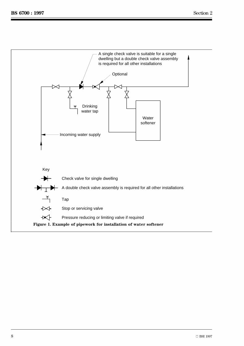
2.2.1.4 Any ion exchange water softeners shall beinstalled downstream of the supply to the drinkingwater taps (see figure 1).
Pipework shall be provided to bypass a water softenerin the event of malfunction or for the purpose ofmaintenance.
COMMENTARY AND RECOMMENDATIONSON 2.2.1.4
Over softening of the water increases the potential formetal dissolution, especially plumbosolvency. If leadpipe exists downstream of the water softenerspecialist advice should be sought.
8 BSI 1997
BS 6700 : 1997 Section 2
Watersoftener
A single check valve is suitable for a singledwelling but a double check valve assembly is required for all other installations
Optional
Incoming water supply
Drinkingwater tap
Check valve for single dwelling
A double check valve assembly is required for all other installations
Tap
Stop or servicing valve
Pressure reducing or limiting valve if required
Key
Figure 1. Example of pipework for installation of water softener
Section 2 BS 6700 : 1997
BSI 1997 9
2.2.2 Type of system
2.2.2.1 The distribution system shall conform to therequirements of the water supplier.
COMMENTARY AND RECOMMENDATIONSON 2.2.2.1
A choice of cold water supply system might not beavailable if the water supplier exercises powers torequire cold water storage. In any case,considerations of pressure and reliability of supply,particularly where dwellings are located at theextremity of mains distribution system, should bestudied.
a) Characteristics of supply via a storage cistern:
1) availability of a reserve of water for use in caseof interruption of the mains supply;
2) additional protection of the mains fromcontamination;
3) reduced risk of water-hammer and reducednoise from outlets, but additional noise generatedby the float-operated valve controlling the watersupply to the cistern;
4) a constant low pressure with reduced risk ofleakage and which is suitable for mixer fittings inconjunction with low pressure (vented) hot watersupply, but the pressure available is usuallyinsufficient for some types of taps and may not besufficient for satisfactory showering in the absenceof a booster pump;
5) risk of frost damage;
6) space occupied and cost of storage cistern,structural support and additional pipework;
7) need to ensure that the cistern is continuouslyprotected against the ingress of any contaminant.
b) Characteristics of supply directly from a watermain:
1) smaller pipes may be used in most cases exceptfor the service pipe which may need to be largerthan the supply pipe to a storage cistern;
2) the higher pressure that is usually available ismore suitable for instantaneous type showerheaters, hose taps and for mixer fittings used inconjunction with a high pressure (unvented) hotwater supply;
3) where single outlet mixer fittings are usedmeasures to prevent backflow may be necessarywhen used in conjunction with a low pressure(vented) hot water supply.
In some cases a combination of the two methods orsupply may be the best arrangement. In a dwelling,for example, the ground floor cold outlets and anyoutside tap could be supplied under mains pressurewhile all other cold water outlets could be fed from astorage cistern.
2.2.2.2 Systems in buildings other than dwellings
For buildings other than dwellings, the method ofsupply shall be related to the size and usage of thebuilding and the number of appliances to be served.
COMMENTARY AND RECOMMENDATIONSON 2.2.2.2
In the case of small buildings where the waterconsumption is likely to be comparable to that of adwelling house, the options stated in 2.2.2.1 should beconsidered. For larger buildings, it will be acceptablefor all water, except drinking water, to be suppliedindirectly via a storage cistern or cisterns.
Drinking water should be taken directly from thewater supplier's main wherever practicable or, whencircumstances dictate otherwise, from a cisternprotected in accordance with 2.2.3.1.
2.2.2.3 Pumped systems
The prior written consent of the water supplier shallbe obtained before a pump is connected in or to asupply pipe.
COMMENTARY AND RECOMMENDATIONSON 2.2.2.3
Where the available pressure is insufficient to supplythe whole of a building and the water supplier isunable to increase the supply pressure in thesupplier's mains, consideration should be given toinstalling a pumped system.
When deciding on the method of pumping and on thesiting of break tanks and pumps, considerationshould be given to the use of such pressure as may beavailable in the mains supply. In all systems,precautions have to be taken to ensure that backflowdoes not occur from the distribution pipework andpumping plant (see 2.6.1.3 and 2.6.3).

10 BSI 1997
BS 6700 : 1997 Section 2
2.2.3 Storage cisterns
2.2.3.1 General
2.2.3.1.1 Drinking water storage cisterns and coversshall not impart taste, colour, odour or toxicity to thewater, nor promote or foster microbial growth(see 2.6). Any cistern from which water for domesticpurposes may be drawn shall be watertight and shallbe:
a) fitted with a rigid, close fitting and securely fixedcover which is not airtight but excludes light andinsects from the cistern, fits closely around any ventpipe, made of materials which will not shatter orfragment when broken and will not contaminate anywater which condenses on its underside;
b) where necessary, lined or coated with a materialsuitable for use in contact with drinking water;
c) where necessary, insulated against heat and frost;
d) supplied from a supply pipe from the watersupplier's mains or from a pump drawing waterfrom a cistern which is also a watertight closedvessel similarly equipped and supplied as above;
e) when of capacity greater than 1000 l, soconstructed that the interior can be readily inspectedand cleaned, and the inlet control valve adjusted andmaintained without having to remove the cover orthe whole of any cover which is in two or moreparts; and
f) provided with warning and overflow pipes, asappropriate (see 2.2.4), which are constructed andarranged to exclude insects.
COMMENTARY AND RECOMMENDATIONSON 2.2.3.1.1
Table 1 gives recommendations for storage capacitiesrelated to various types of use but these are to beregarded as a guide only. The water supplier shouldbe consulted regarding any particular requirements itmay have in this matter.
In determining the total capacity of cold water storagein the premises concerned, account should be taken of:
a) the need to prevent stagnation by ensuring thatwater is held in storage for as short a time aspossible; and
b) the requirements of any associated water-usingfittings and appliances, particularly where supplyinterruptions could cause damage to property orinconvenience to the consumer.
The probable pattern of water use (draw-off rates andtheir durations) should be determined and accounttaken of any local conditions of low or reduced mainspressures likely to affect cistern refilling at times ofpeak demand.
In single dwellings it is usual for storage cisternssupplying cold water fittings only to have a capacityof 100 l to 150 l, and double this capacity if supplyingall water outlets, hot and cold.
Alternatively, where a constant supply at adequatepressure is a statutory requirement, a maximumcapacity of 80 l per person normally resident shouldprove satisfactory. A larger capacity based on 130 l perperson would be appropriate where cistern refillingnormally takes place only during the night hours.
The water supplier should be consulted beforefinalising cistern capacity to hotels, hostels, officepremises (with or without canteen facilities), schools(day and boarding) and other substantialestablishments.
Separation of capacity among two or more cisternsshould facilitate water distribution, but inlets andoutlets should be located to prevent short-circuitingwithin the cisterns.
Table 1. Recommended minimum storage ofcold water for domestic purposes (hot and coldoutlets)
Type of building or occupation Minimum storage
l
Hostel 90 per bed space
Hotel 200 per bed space
Office premises:
with canteen facilities 45 per employee
without canteen facilities 40 per employee
Restaurant 7 per meal
Day school:
nursery
primary
15 per pupil
secondary
technical
20 per pupil
Boarding school 90 per pupil
Children's home orresidential nursery
135 per bed space
Nurses' home 120 per bed space
Nursing or convalescenthome
135 per bed space
Section 2 BS 6700 : 1997
BSI 1997 11
2.2.3.1.2 The material of a cistern shall be corrosionresistant or shall be coated internally with an approvednon-toxic corrosion resistant material conforming toBS 6920 : Parts 1,2 and 3. The cistern and its cover shallbe designed to have sufficient strength to operatewithout undue deformation.
2.2.3.1.3 The cistern shall be supported on a firmlevel base which is capable of withstanding the weightof the cistern when filled with water to the rim. Everyplastics cistern shall be supported on a flat rigidplatform fully supporting the bottom of the cisternover the whole of its area.
2.2.3.1.4 Access shall be provided as described in2.8.4. Space shall be provided under and around thecistern for maintenance and the outlet of any overflowpipe shall be above outside ground or flood level.
2.2.3.1.5 Every cistern providing drinking water shallbe protected from ingress of contaminants. Cisternssunk in the ground shall have special measures todetect leakage.
Where the ground water table dictates, buried cisternsshall be anchored to prevent them lifting when emptyor partially filled.
2.2.3.1.6 Except for interconnected cisterns arrangedto store water at the same water level, every pipesupplying water to a cistern shall be fitted with afloat-operated valve or some other equally effectivedevice to control the inflow of water and maintain it atthe required level. The inlet control device shall besuitable for the particular application.
When a float-operated valve is used it shall either:
a) conform to BS 1212 : Parts 1, 2, 3 or 4 and be usedwith a float conforming to BS 1968 or BS 2456 of thecorrect size corresponding to the length of the leverarm and the water supply pressure; or
b) where any other float-operated valve or otherlevel control device is used, it shall conform to theperformance requirements of BS 1212 :Parts 1, 2, 3 or 4 where applicable to thecircumstances of its use and shall be clearly markedwith the water pressure, temperature and othercharacteristics for which it is intended to be used(see also 2.6.3).
Every float-operated valve shall be securely fixed tothe cistern it supplies and where necessary braced toprevent the thrust of the float causing the valve tomove and so affect the water level at which it closes.This water level shall be at least 25 mm below thelowest point of the warning pipe connection or, if nowarning pipe is fitted, at least 50 mm below the lowestpoint of the lowest overflow pipe connection.
2.2.3.1.7 All cold water distributing pipes fromcisterns shall be connected at the lowest point on thecistern.
2.2.3.1.8 Connections to distributing pipes feeding hotwater apparatus shall be set at a level at least 25 mmabove connections to pipes feeding cold water outlets.
COMMENTARY AND RECOMMENDATIONS ON2.2.3.1.8
This requirement will minimize the risk of scaldingfrom mixer fittings such as showers, should the watersupply fail.
2.2.3.2 Large cisterns
Cisterns over 1000 l capacity shall additionally conformto the following requirements.
To avoid interruption of the water supply whencarrying out repairs or maintenance, the cistern shallbe provided with compartments or a standby cistern.
A washout pipe shall not be connected to a drain butmay be arranged to discharge into open air atleast 150 mm above a drain if required.
COMMENTARY AND RECOMMENDATIONSON 2.2.3.2
A washout pipe should be provided flush with thebottom of the cistern at its lowest point. Wherepracticable, the floor of the cistern should be laid to aslight fall to the washout pipe for cleaning purposes.The washout pipe outlet should be controlled by asuitable fullway valve and blanked off with a plug orflange when not in use.
Sometimes, particularly in the case of a complex ofbuildings, because of the larger volume of storagerequired or to provide the necessary head, it may benecessary to support the cistern in an independentstructure outside the building(s). Although such astorage facility is often referred to as a tank or watertower, it is, by definition, a cistern.
Cisterns mounted outside buildings, whether fixed tothe building itself or supported on an independentstructure, should be enclosed in a well ventilated, butdraughtproof, housing constructed to prevent ingressof birds, animals, and insects, but providing access tothe interior of the cistern by authorized persons forinspection and maintenance. Ventilation openingsshould be screened by a corrosion-resistant mesh witha maximum aperture size of 0.65 mm.

12 BSI 1997
BS 6700 : 1997 Section 2
2.2.4 Warning and overflow pipes
Every cistern of capacity (if filled to the level at whichwater just starts to flow through any overflow pipe) upto 1000 l shall be fitted with a warning pipe, and noother overflow pipe. Cisterns of capacityexceeding 1000 l shall be fitted with one or moreoverflow pipes. For capacities up to 5000 l the lowestoverflow pipe shall be a warning pipe. For capacitiesover 5000 l but not greater than 10 000 l, either thelowest overflow pipe shall be a warning pipe, or adevice shall be fitted that indicates when the water inthe cistern reaches a level that is at least 50 mm belowthe lowest point of the lowest overflow pipeconnection. For capacities greater than 10 000 l, eitherthe lowest overflow pipe shall be a warning pipe or adevice shall be fitted that gives an audible or visualalarm when the water reaches the level of overflowingand which acts independently of the normal serviceinlet control valve.
Overflow and warning pipes shall be made of rigid,corrosion resistant material; no flexible hose shall beconnected to or form part of any overflow or warningpipe. When a single overflow pipe is fitted its boreshall be greater than that of the inlet pipe to thecistern and in no case shall any warning pipe be lessthan 19 mm internal diameter.
No warning or overflow pipe shall rise in level outsidethe cistern.
Every warning pipe shall discharge water immediatelythe water in the cistern reaches the overflowing leveland shall discharge in a conspicuous position,preferably outside the building where this isappropriate.
It is permissible for the separate warning pipes fromseveral storage or WC flushing cisterns to be combinedinto one outlet, provided that the source of anyoverflow may be readily identified and that anyoverflow from one cistern cannot discharge intoanother. No warning pipe shall be arranged todischarge into a WC pan via the flush pipe.
COMMENTARY AND RECOMMENDATIONS ON 2.2.4
The overflow pipe or pipes should be able to carryaway all the water which is discharged into thecistern in the event of the inlet control devicebecoming defective, without the water level reachingthe spill-over level of the cistern or submerging thedischarge opening of the inlet pipe or valve.
Where overflow and warning pipes discharge throughthe external wall of a building they should bearranged so as to prevent the inward flow of cold airby turning down the warning pipe into the cisternand below the water line except where this couldinterfere with the operation of the flushingmechanism or float-operated valve in a WC flushingcistern.
2.2.5 Stopvalves
2.2.5.1 Stopvalves fitted to supply pipes below groundshall conform to BS 2580 or BS 5433 when the pipe isless than 50 mm nominal size, with BS 2580, BS 5163 orBS 5433 when the pipe is 50 mm nominal size, and withBS 5163 when the pipe is greater than 50 mm nominalsize. Stopvalves fitted to service pipes above groundshall either conform to the appropriate requirementsfor stopvalves fitted to supply pipes below ground or,when the pipe is not larger than 50 mm nominal size,to BS 1010 : Part 2 (see table 2).
Table 2. British Standards for stopvalves
Nominal size of pipe British Standard
Above ground Belowground
50 mm or smaller BS 1010 : Part 2 BS 2580
BS 2580 BS 5433
BS 5433
50 mm or larger BS 5163 BS 5163
The stopvalve components of composite fittingsincorporating stopvalves shall conform to therequirements for stopvalves.
When a stopvalve is installed on an underground pipeit shall be enclosed in a pipe guard under a surfacebox.
2.2.5.2 In every building or part of a building towhich a separately chargeable supply of water isprovided and in any premises occupied as a dwelling,whether or not separately charged for a supply ofwater, a stopvalve shall be provided that controls thewhole of the supply to those premises without shuttingoff the supply to any other premises. This stopvalveshall, so far as is practicable, be installed within thebuilding or premises concerned in an accessibleposition above floor level and close to the point ofentry of the pipe supplying water to that premises,whether this be a supply pipe or a distributing pipe.
In addition, where a common supply or distributingpipe provides water to two or more premises, it shallbe fitted with a stopvalve that controls the watersupply to all of the premises supplied by that pipe.This stopvalve shall be installed either inside or outsidethe building in a position to which every occupier ofthe premises supplied has access.
A stopvalve shall be installed in every pipe supplyingwater to any structure erected within the curtilage of abuilding but having no access from the main building.This stopvalve shall be located in the main building asnear as practicable to the exit point of the supply pipeto the other structure or if this is not practicable in theother structure itself as near as possible to the entrypoint of the supply.
Section 2 BS 6700 : 1997
BSI 1997 13
COMMENTARY AND RECOMMENDATIONSON 2.2.5.2
In addition to the above requirements, it is oftenadvantageous where a building is divided intoseparately occupied parts, for the supply to each partto be capable of being shut off by a second stopvalveinstalled outside that part without shutting off thesupply to other parts of the building. The principle onwhich these requirements and recommendations arebased is to provide a ready means of isolating anyprivate or common supply causing damage ornuisance or for the purpose of effecting repairs,replacements or alterations. Any occupier should beable to drain down his supply to avoid frost damageand to shut off his own supply or a supply inunoccupied premises which is causing damage ornuisance by means of a stopvalve under his control orto which he has ready access.
2.2.6 Servicing valves
2.2.6.1 Servicing valves shall be provided and locatedin accessible positions so as to enable the flow ofwater to individual or groups of appliances to becontrolled and to limit the inconvenience caused byinterruption of supply during repairs.
2.2.6.2 A servicing valve shall be protected againstunauthorized use. Screwdown servicing valves shallnot be of loose washer plate design.
2.2.6.3 A servicing valve shall be fitted upstream of,and as close as practicable to, every float-operatedvalve or other device used to control the inflow andlevel of water.
Every pipe taking water from a cistern of capacityexceeding 18 l shall be fitted with a servicing valvenear the cistern.
Pipes connecting feed cisterns to primary circuits shallnot be fitted with servicing valves where the capacityof the cistern does not exceed 18 l.
COMMENTARY AND RECOMMENDATIONSON 2.2.6.3Having regard to the hydraulic resistance ofscrewdown type valves, it is permissible for copperalloy gatevalves conforming to BS 5154 to be used forthis purpose. Specially designed spherical valves areavailable in the smaller sizes and are well suited forfitting near to single outlet fittings and appliances asservicing valves.
2.2.7 Draining taps
Every pipe which supplies water to a premises shall befitted with a draining tap and arranged so that whenthe stopvalve installed according to 2.2.5.2 is closed,and the draining tap is open, the supply pipedownstream of the stopvalve can be drained(see 2.7.5).
Draining taps shall be fixed over a drain or haveprovision for discharging the water to the nearestconvenient point for disposal. The draining taps on anysupply or distributing pipe shall not be buried in theground or so placed that their outlet is in danger ofbeing flooded.
COMMENTARY AND RECOMMENDATIONS ON 2.2.7
Combined stopvalves and draining taps are aconvenient way of providing facilities for draining.
The pipe runs on the downstream of every stopvalveshould be arranged so as to drain continuouslytowards draining taps or draw-off taps at the lowpoints. All cisterns, tanks, cylinders and boilersshould be fitted with draining taps unless they can bedrained through pipes leading to draining taps ordraw-off taps elsewhere; provision should be made fordraining both the primary and secondary parts of anindirect hot water cylinder or calorifier. Provisionshould be made for draining low level pipes such asthose laid in ducts under a ground floor.
All draining taps should be capable of being fittedwith removable hosepipes unless installed over adrain or discharging into a permanent draining pipe.Where a draining tap is necessarily at such a level orin such a position that complete drainage cannot beobtained, even by the aid of a hosepipe and syphonicaction, then a sump that can be emptied by bailing orpumping should be provided to receive the waterdrained from the tap.
Adequate facilities should be provided to permit entryof air into the system when draining down. Where thetaps and float-operated valves in the system are notsuitably located for this purpose, special air inletvalves should be fitted in appropriate locations.
When a sump is used it should be arranged so thatthe water level in it will at all times be kept below theoutlet of the drain tap to preserve an air gap andprevent backflow. Similarly, outlets of hoses connectedto draining taps should be arranged to dischargefreely into the air, at no time should such hose outletsbe allowed to become submerged.
For effective draining, it is essential that air entersthe pipework freely and draw-off taps, float-operatedvalves and air inlet valves should be open for thispurpose when draining is being carried out. Hotwater cylinders are liable to collapse if air cannotenter the system.
Draining taps should be used for draining purposesonly. Where a draw-off tap is used for draining theinstallation, it should not be fitted with a hose unlessit has backflow protection as indicated in table 5 andin accordance with the water byelaws (see A.2).
Attention is drawn to the situation where theprovision of check valves and double check valveassemblies for backflow prevention at draw off taps,particularly those with flexible hoses, and otherequipment may also prevent air entering the systemduring a draining operation.
14 BSI 1997
BS 6700 : 1997 Section 2
2.2.8 Revenue meter installations
2.2.8.1 General
The consumer shall consult with the water supplier tocarry out the installation of a revenue meter, withregard to any requirements concerning the installationadditional to those specified in 2.2.8.2 to 2.2.8.5before work is begun.
COMMENTARY AND RECOMMENDATIONSON 2.2.8.1
Meters on the incoming supply to a premises, forrevenue charging purposes, are usually supplied bythe water supplier and sited by agreement between theconsumer and the water supplier.
Wherever possible meters should be installed at ornear the street boundary of the premises supplied,which is the limit of the responsibility of the watersupplier for maintenance of the communication pipe.Where a meter is to be installed near the boundary ofa premises, the distance to the public highway shouldnot exceed 10 m. However, in the case of flats andindustrial premises or shops in multiple occupation,as well as existing premises opting for a meter for thefirst time, an internal installation may be necessaryand is acceptable provided it registers the wholesupply.
The meter should be protected from the risk of damageby shock or vibration induced by the surroundings atthe place of installation.
2.2.8.2 Meters
Meters shall conform to BS 5728 : Part 1, with suitableconnectors to facilitate future meter changes withoutthe use of heat or major disturbance of the pipework.
2.2.8.3 Bonding
A suitable conductor shall be installed for bondingbetween inlet and outlet pipework connections towater meters, water suppliers' stopvalves or otherwater conveying components in a metal water supplypipe to ensure equipotential bonding applies to anypipework temporarily disconnected for the purpose ofremoving such components for replacement ormaintenance (see 3.1.8 and 4.2.5).
For dwellings a bond of at least 6 mm2 cross-sectionshall be connected prior to attaching the pipework andshall remain in place following installation.
COMMENTARY AND RECOMMENDATIONSON 2.2.8.3
These requirements are necessary on both internaland external installations for protection of theinstaller against electrical fault and for maintenanceof the earth connection.
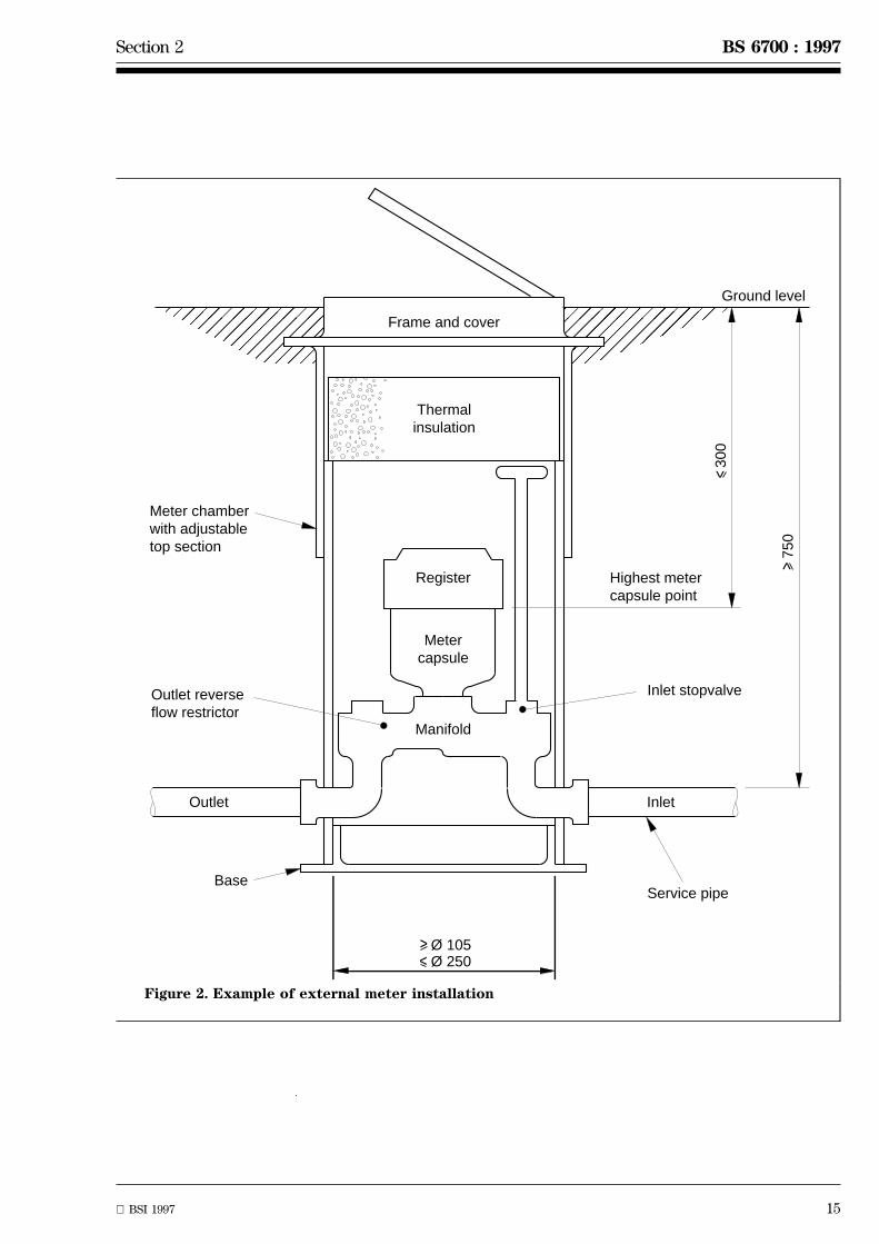
2.2.8.4 External installations
2.2.8.4.1 In external meter installations the metershall be installed below ground in a position accessiblefor meter reading and changing, with the dialuppermost.
The chamber shall be fitted with a cover marked`water meter', of sufficient strength to carry the loadsto which it may be subjected and fitted with slots orlifting eyes.
Pipes, cables or drains other than the meter pipeworkshall not pass through the meter chamber.
The chamber shall be sized so that there is amplespace available for removing the meter using thenecessary hand tools.
Space shall be left for the extraction of bolts fromflanges for ready dismantling of joints and no part ofthe meter assembly shall be built into the walls of thechamber or concreted into the chamber.
The pipe on both sides of the meter assembly shallhave a clearance space around it through the wall ofthe chamber to facilitate exchange of the meter. Wherethe chamber needs to be watertight, the clearance shallbe fitted with a sealing material approved by the watersupplier and sufficient length of pipe left inside the pitto facilitate meter exchange.
Pipework on both sides of the meter assembly shall befirmly fixed to prevent movement of any flexible jointswithin the meter assembly. Nevertheless, suchanchorage shall leave sufficient room for connectingand disconnecting the meter making use of theadaptors provided. The meter shall also be supportedon the underside so as not to create differential loadsbetween the meter and its connecting pipework.
There shall be a valve which isolates the meter onboth the inlet and the outlet.
COMMENTARY AND RECOMMENDATIONSON 2.2.8.4.1
For housing and other installations where themaximum water requirement does not exceed 3500 l/hthe chamber may be constructed of glass reinforcedplastics or PVC (see figure 2).
For meters where the water flow exceeds 3500 l/h thechamber should be constructed of brick or concrete.
The clear opening of the surface box should be thesame as the internal dimensions of the chamber.
Steel framed, concrete filled covers to chambers are notrecommended on account of their weight and theirliability to flex causing the concrete to crack and thecover to jam.
Section 2 BS 6700 : 1997
BSI 1997 15
�����������������������
���������������
Outlet Inlet
Frame and cover
Thermalinsulation
Register
Metercapsule
Manifold
Inlet stopvalve
Service pipe
Meter chamberwith adjustabletop section
Outlet reverseflow restrictor
Base
Highest metercapsule point
300
750
Ground level
^
^ Ø 105
^
^
Ø 250
Figure 2. Example of external meter installation

16 BSI 1997
BS 6700 : 1997 Section 2
������Incoming stop valve
Straight connectors suppliedwith meter
Outlet stop valve
Drainvalve on outlet of meter(moved if necessary)
Floor
Approved electricalcross bond
Direction of flow
1.5
m m
ax.
Figure 3. Example of meter installation inside building
2.2.8.4.2 Any stopvalve in a meter chamber shallconform to table 2.
2.2.8.5 Internal meters
2.2.8.5.1 Internal meters shall be fixed horizontally orvertically and with the dial not more than 1.5 m abovefloor level and readily visible for reading.
Where the existing pipework is, or can be,re-positioned so as to be parallel to the wall and is notless than 50 mm away from it, installations shall be asindicated in figure 3.
COMMENTARY AND RECOMMENDATIONSON 2.2.8.5.1
Where a consumer wishes to limit access to the meterfor reading purposes, a remote readout device may beinstalled if the water supplier agrees.

Section 2 BS 6700 : 1997
BSI 1997 17
2.2.8.5.2 Pipework shall be adequately supported,leaving sufficient room for changing the meter with theconnections provided.
2.2.8.5.3 The meter shall be installed downstream ofthe internal stopvalve and as close to it as possible.Where a drain valve is required, in accordance with thebyelaws, it shall be installed immediately downstreamof the meter.
COMMENTARY AND RECOMMENDATIONSON 2.2.8.5.3
The length of pipe between the stopvalve and the metercannot easily be drained and will thus requireeffective protection against damage from frost inaccordance with 2.7.
2.2.8.5.4 A second stopvalve or servicing valve shallbe installed downstream of the meter.
2.2.8.5.5 Where the installation of meters in exposedlocations, e.g. garages subject to frost, is unavoidableand agreed by the water supplier, adequate insulationin accordance with 2.7.3 shall be provided but not soas to seriously impede reading or changing the meter.
2.2.9 Non-revenue meters
The installation of non-revenue meters shall conformto 2.2.8 except that the water supplier need not beconsulted.
2.3 Hot water services
2.3.1 General principles
The hot water service shall be designed to provide hotwater at the point of use, in the quantities and at thetemperatures required by the user.
COMMENTARY AND RECOMMENDATIONS ON 2.3.1
Under normal conditions the temperature of the storedwater should never exceed 65 ÊC. A stored watertemperature of 60 ÊC is considered sufficient to meetall normal requirements and will minimizedeposition of scale in hard water areas. Minimumtemperatures are given in 2.1.2.
The design should take account of maintenance, fuelcosts, efficiency of the system and the safety of theuser. The relevant codes of practice for installationshould be used, e.g. BS 5546 for gas installations.
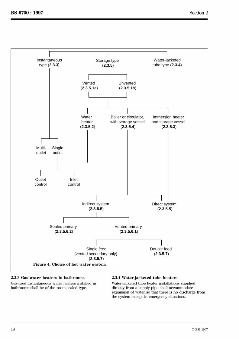
2.3.2 Choice of system
Where the user requirements are not specified, and inparticular where the user is not known, as inspeculative housing developments for example, anassessment of user needs shall be made on the basis ofthe size and type of building, experience andconvention.
Where a dwelling has only one bathroom it shall beassumed that immediately after filling a bath, some hotwater will be required for kitchen use, but a secondbath will not be required within 20 min to 30 min.Where a dwelling has two or more bathrooms it shallbe assumed that all the installed baths will be filled insuccession and that hot water will immediately berequired for kitchen use (see figure 4).
COMMENTARY AND RECOMMENDATIONS ON 2.3.2
Data on which this assessment is made shouldinclude the following:
Hot water (60 ÊC) used indwellings:
35 l to 45 l per personper day
Average bath: 60 l at 60 ÊC plus
40 l at 10 ÊC
or 100 l at 40 ÊC
Shower: 0.05 l to 0.10 l/s at 40 ÊC
Power shower: Up to 0.2 l/s at 40 ÊC
Wash basin hot tap: 0.10 l to 0.15 l/s at 40 ÊCto 60 ÊC
Kitchen sink 0.10 to 0.20 l/s at 60 ÊC
NOTE. Although temperatures of 40 ÊC are quoted above, these areachieved by mixing cold and hot water as required.
18 BSI 1997
BS 6700 : 1997 Section 2
Vented (2.3.5.1a)
Instantaneoustype (2.3.3)
Storage type (2.3.5)
Water-jacketedtube type (2.3.4)
Water heater
(2.3.5.2)
Boiler or circulator,with storage vessel
(2.3.5.4)
Immersion heaterand storage vessel
(2.3.5.3)
Indirect system (2.3.5.5)
Direct system (2.3.5.5)
Vented primary (2.3.5.6.1)
Sealed primary (2.3.5.6.2)
Double feed (2.3.5.7)
Single feed(vented secondary only)
(2.3.5.7)
Outletcontrol
Inletcontrol
Multi-outlet
Singleoutlet
Unvented (2.3.5.1b)
Figure 4. Choice of hot water system
2.3.3 Gas water heaters in bathrooms
Gas-fired instantaneous water heaters installed inbathrooms shall be of the room-sealed type.
2.3.4 Water-jacketed tube heaters
Water-jacketed tube heater installations supplieddirectly from a supply pipe shall accommodateexpansion of water so that there is no discharge fromthe system except in emergency situations.
Section 2 BS 6700 : 1997
BSI 1997 19
COMMENTARY AND RECOMMENDATIONS ON 2.3.4
The cold water feed may be from a supply pipe orfrom a storage cistern. The water drawn for usepasses through a heat exchanger in a reservoir ofprimary water heated by an integral or separateboiler. The size of this reservoir, which in somedesigns can include the space-heating circuit, the rateof heat input to it and the heat exchangercharacteristics determine the amount and rate of flowof hot water that can be provided withoutunacceptable temperature drop. The primary circuitmay be vented or sealed.
The performance characteristics of individualappliances should be ascertained from themanufacturers.
2.3.5 Storage-type hot water systems
2.3.5.1 Choice of vented or unvented system
The choice between the vented and the unvented typeof installation shall be made in conjunction with thechoice of method of cold water supply (see 2.2.2).Whichever system is installed, it shall conform to therelevant requirements of 2.4.
COMMENTARY AND RECOMMENDATIONSON 2.3.5.1
Except for supplies to dual stream fittings, mixingfittings should be supplied with comparable hot andcold water supply pressures.
A summary of the main differences between ventedand unvented systems is as follows.
a) Vented systems: vented domestic hot waterservice systems are fed with cold water from astorage cistern which is situated above the highestoutlet to provide the necessary pressure in thesystem and which accommodates expansion of thewater when it is heated. An open vent pipe runsfrom the top of the hot water storage vessel to apoint above the water storage cistern, into which itis arranged to vent. Explosion protection involvingno mechanical devices is provided by the open ventand the cistern.
b) Unvented systems: unvented systems can besupplied from a storage cistern, either directly orthrough a booster pump, but usually from thesupply pipe, either directly or via a pressurereducing valve. The main characteristics ofunvented systems are as follows.
1) Explosion protection is provided by safetydevices.
2) Systems depend upon pressure continuity andthe hot water flow cannot be guaranteed ifpressures fall.3) In unvented systems supplied from a supplypipe the absence of a storage cistern may reducethe risk of frost damage to property and removesthe source of refill, or float-operated valve noise.4) The safety aspects of unvented, storage-typehot water systems are subject to the requirementsof the building regulations (see A.1).
2.3.5.2 Storage water heaters
2.3.5.2.1 Non-pressure or inlet controlled type
No hose or other connection shall be made to theoutlet of a non-pressure or inlet-controlled storage-typewater heater and the outlet shall not be controlled by avalve or tap.
Commentary and recommendations on 2.3.5.2.1
Special taps and mixer taps in which the tapmechanism controls the cold water inlet to the heaterwhile the hot water from the heater is dischargedthrough the tap outlet can be used when specified bythe heater manufacturer, provided the tap outletremains unobstructed.
2.3.5.2.2 Pressure or outlet controlled type
The heater shall be suitable for the supply pressureand there shall be appropriate arrangements toaccommodate expansion of the heated water.
COMMENTARY AND RECOMMENDATIONSON 2.3.5.2.2
Many pressure-type water heaters are designed to besupplied from a storage cistern only and will notwithstand mains water pressures.
For installations in small dwellings a capacity of100 l to 150 l is sufficient to provide a hot watersupply including a supply to a bath. Heaters designedto take advantage of off-peak electricity tariffs mayhave a capacity of 200 l or more.
2.3.5.3 Storage vessel with electric immersionheater
The storage vessel shall conform to the relevantrequirements of 2.6 and shall be corrosion resistant.The immersion heater or heaters shall conform toBS 3456 : Section 2.21; all electrical controls shallconform to BS 3955.
Immersion heaters and controls shall be so locatedthat insertion, removal and adjustment can easily beperformed.
The insertion of an immersion heater into the storagevessel of an indirect system provides direct heating sofar as the immersion heater is concerned and thesafety controls appropriate to a direct system shall befitted.
COMMENTARY AND RECOMMENDATIONSON 2.3.5.3
This appliance is site assembled, and it is importantto ensure that it is protected against bursting inaccordance with 2.4 for a direct system and that anybackflow prevention devices required by 2.6 arecorrectly fitted.
Immersion heaters form a convenient means ofproviding supplementary water heating in systemscombining hot water supply and space heating(see 2.3.5.6).
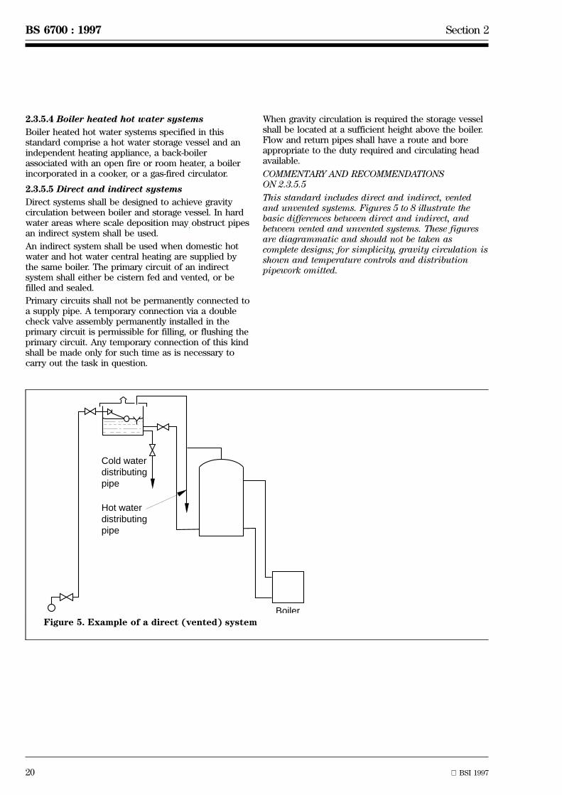
20 BSI 1997
BS 6700 : 1997 Section 2
Cold waterdistributingpipe
Hot waterdistributingpipe
BoilerFigure 5. Example of a direct (vented) system
2.3.5.4 Boiler heated hot water systems
Boiler heated hot water systems specified in thisstandard comprise a hot water storage vessel and anindependent heating appliance, a back-boilerassociated with an open fire or room heater, a boilerincorporated in a cooker, or a gas-fired circulator.
2.3.5.5 Direct and indirect systems
Direct systems shall be designed to achieve gravitycirculation between boiler and storage vessel. In hardwater areas where scale deposition may obstruct pipesan indirect system shall be used.
An indirect system shall be used when domestic hotwater and hot water central heating are supplied bythe same boiler. The primary circuit of an indirectsystem shall either be cistern fed and vented, or befilled and sealed.
Primary circuits shall not be permanently connected toa supply pipe. A temporary connection via a doublecheck valve assembly permanently installed in theprimary circuit is permissible for filling, or flushing theprimary circuit. Any temporary connection of this kindshall be made only for such time as is necessary tocarry out the task in question.
When gravity circulation is required the storage vesselshall be located at a sufficient height above the boiler.Flow and return pipes shall have a route and boreappropriate to the duty required and circulating headavailable.
COMMENTARY AND RECOMMENDATIONSON 2.3.5.5
This standard includes direct and indirect, ventedand unvented systems. Figures 5 to 8 illustrate thebasic differences between direct and indirect, andbetween vented and unvented systems. These figuresare diagrammatic and should not be taken ascomplete designs; for simplicity, gravity circulation isshown and temperature controls and distributionpipework omitted.
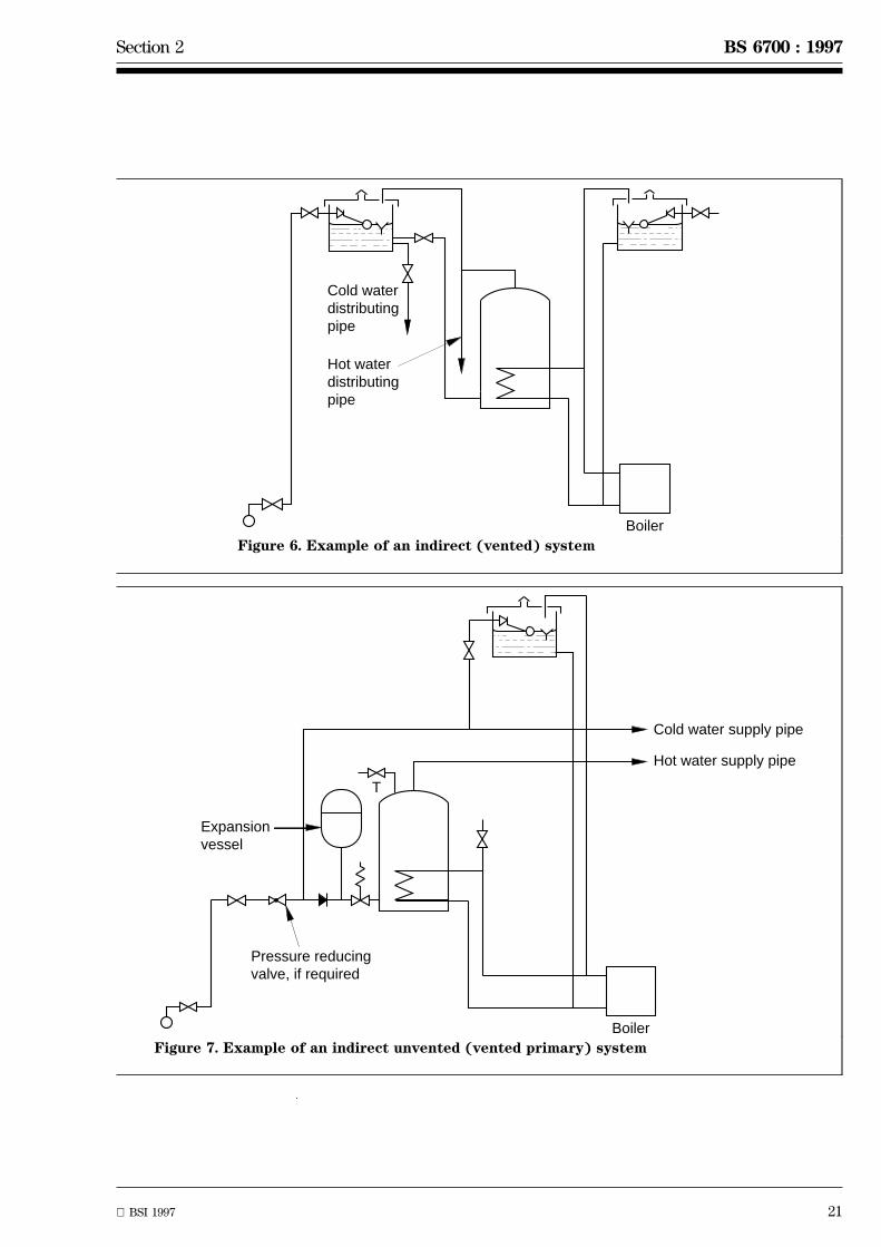
Section 2 BS 6700 : 1997
BSI 1997 21
Cold waterdistributingpipe
Hot waterdistributingpipe
BoilerFigure 6. Example of an indirect (vented) system
Cold water supply pipe
Hot water supply pipe
Boiler
T
Expansionvessel
Pressure reducingvalve, if required
Figure 7. Example of an indirect unvented (vented primary) system
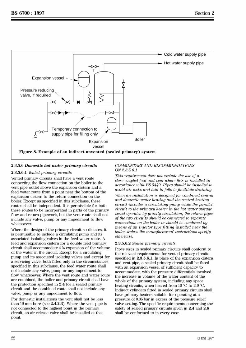
22 BSI 1997
BS 6700 : 1997 Section 2
Cold water supply pipe
Hot water supply pipe
Boiler
T
Expansion vessel
Expansionvessel
Temporary connection tosupply pipe for filling only
Pressure reducingvalve, if required
Figure 8. Example of an indirect unvented (sealed primary) system
2.3.5.6 Domestic hot water primary circuits
2.3.5.6.1 Vented primary circuits
Vented primary circuits shall have a vent routeconnecting the flow connection on the boiler to thevent pipe outlet above the expansion cistern and afeed water route from a point near the bottom of theexpansion cistern to the return connection on theboiler. Except as specified in this subclause, theseroutes shall be independent. It is permissible for boththese routes to be incorporated in parts of the primaryflow and return pipework, but the vent route shall notinclude any valve, pump or any impediment to flowwhatsoever.
Where the design of the primary circuit so dictates, itis permissible to include a circulating pump and itsassociated isolating valves in the feed water route. Afeed and expansion cistern for a double feed primarycircuit shall accommodate 4 % expansion of the volumeof the water in the circuit. Except for a circulatingpump and its associated isolating valves and except fora servicing valve, both fitted only in the circumstancesspecified in this subclause, the feed water route shallnot include any valve, pump or any impediment toflow whatsoever. Where the vent route and water routeare combined, the boiler and primary circuit shall havethe protection specified in 2.4 for a sealed primarycircuit and the combined route shall not include anyvalve, pump or any impediment to flow.
For domestic installations the vent shall not be lessthan 19 mm bore (see 2.4.2.3). Where the vent pipe isnot connected to the highest point in the primarycircuit, an air release valve shall be installed at thatpoint.
COMMENTARY AND RECOMMENDATIONSON 2.3.5.6.1
This requirement does not exclude the use of aclose-coupled feed and vent where this is installed inaccordance with BS 5449. Pipes should be installed toavoid air locks and laid to falls to facilitate draining.
When an installation is designed for combined centraland domestic water heating and the central heatingcircuit includes a circulating pump while the parallelcircuit to the primary heater in the hot water storagevessel operates by gravity circulation, the return pipesof the two circuits should be connected to separateconnections on the boiler or should be combined bymeans of an injector type fitting installed near theboiler, unless the manufacturers' instructions specifyotherwise.
2.3.5.6.2 Sealed primary circuits
Pipes sizes in sealed primary circuits shall conform tothe relevant requirements for vented primary circuitsspecified in 2.3.5.6.1. In place of the expansion cisternand vent pipe, a sealed primary circuit shall be fittedwith an expansion vessel of sufficient capacity toaccommodate, with the pressure differentials involved,the increase in volume of the water content of thewhole of the primary system, including any spaceheating circuits, when heated from 10 ÊC to 110 ÊC.Indirect cylinders fitted in sealed primary circuits shallhave primary heaters suitable for operating at apressure of 0.35 bar in excess of the pressure reliefvalve setting. The specific requirements concerning thesafety of sealed primary circuits given in 2.4 and 2.6shall be conformed to in every case.

Section 2 BS 6700 : 1997
BSI 1997 23
2.3.5.7 Double feed and single feed primarycircuits
The primary circuit shall either be fed independently ofthe secondary system, e.g. double feed primary circuit,or be fed from the secondary system by using a hotwater cylinder incorporating a special primary heatexchanger, i.e. single feed primary circuit. A single feedindirect cylinder shall only be used when both primaryand secondary systems are of the vented type. Where asingle feed indirect cylinder is used:
a) the cylinder shall conform to BS 1566 : Part 2 andshall be installed in accordance with the cylinderand appliance manufacturers' instructions;
b) where the primary circuit is pumped, the statichead of the system shall be in excess of themaximum pump head;
c) no corrosion inhibitor or additive shall beintroduced into the primary circuit;
d) the recommendations of the manufacturers of theboiler and the radiators as to the suitability of theirproducts for use in this system shall be followed.
2.3.6 Supplementary water heating andindependent summer water heating
Where supplementary electric heating is to be used inconjunction with a boiler, the height of the storagevessel above the boiler shall not be less than 1 m inorder to prevent circulation of hot water from thestorage vessel to the boiler.
COMMENTARY AND RECOMMENDATIONS ON 2.3.6
It is permissible for supplementary water heating andindependent summer water heating to be provided inthe storage vessel by an electric immersion heater, agas-fired circulator, a heat pump or from solar energy.
Supplementary hot water may also be provided in theform of a single point gas or electric heater at thepoint of use.
2.3.7 Water heating by solar energy
Solar water heating shall be in accordance withBS 5918.
COMMENTARY AND RECOMMENDATIONS ON 2.3.7
Solar energy may be used to augment a conventionaldomestic water heating system of the boiler orimmersion heater type, although in sunny weathersolar energy alone may be sufficient.
2.3.8 Secondary distribution systems
In hot water systems incorporating a hot water storagevessel, the hot water supply or distributing pipe shallbe arranged to be from the top of the vessel or as nearthereto as practicable and always above any primaryflow connection.
COMMENTARY AND RECOMMENDATIONS ON 2.3.8
Secondary water systems should be fed from a coldwater storage cistern and fitted with an open ventpipe, or of unvented type supplied with cold water bygravity from a cold water storage cistern or from themains supply to the building, either directly orthrough a pressure reducing valve.
To promote maximum economy of fuel and water thehot water distribution system should be designed sothat hot water appears shortly after the taps areopened. To this end terminal branches should be asshort as possible. The hot water pipe feeding a spraytap for hand washing should not exceed 1 m in length.When delivery points are situated at a distance fromthe water heater or hot water storage vessel,consideration should be given to the use of a separatewater heater installed closer to those delivery points orinsulating and electrically trace heating the flowpipework (see 2.7.4).
As an alternative a secondary circuit with flow andreturn pipes to the storage vessel could be consideredbut secondary circuits inevitably dissipate heat andshould be avoided where possible. The return pipeshould be connected to the hot water storage vessel ata point not lower than the level of the boiler flow pipeconnection if there is one. (see 2.4).
2.3.9 System components
2.3.9.1 Cold feed pipe
The cold feed pipe to the hot water storage vessel orwater heater shall be sized in accordance with 2.5. Itshall discharge near the bottom of the heaters orstorage vessels and if the system is cistern fed thispipe shall not supply any other fitting. A separate coldfeed pipe from a separate expansion cistern shall beprovided to the lowest point of a vented primarycircuit in an indirect system unless a single feed hotwater cylinder is used.
A servicing valve or stopvalve with a fixed washerplate shall be provided in a convenient and accessibleposition in every cold feed pipe other than those to avented primary circuit which shall have a valve onlywhen the capacity of the expansion cisternexceeds 18 l (see 2.3.5.6.1).
In direct type boiler systems the cold feed pipe and thereturn pipe to the boiler shall have their ownconnections to the hot water storage vessel.
2.3.9.2 Open vent pipe
The vent pipe to a storage type hot water system shallbe taken from the top of the storage vessel or thehighest point of the distribution pipework to a pointabove the cold feed cistern. An offset shall be includedin the vent pipe close to its point of connection to thehot water storage vessel.
When a vented primary circuit is used in an indirectsystem, unless a single feed hot water storage cylinderis used, the vent pipe shall run from the highest pointof the primary circuit to a point above the primaryfeed and expansion cistern at a height that will preventa discharge of water from vent pipe and/or airentrainment into the system under normal workingconditions. Due allowance shall be made for the headinduced by any circulating pump used (see BS 5449 :Part 1).

24 BSI 1997
BS 6700 : 1997 Section 2
For gravity circulation systems this height shall be notless than 150 mm plus 40 mm for every metre in theheight of the overflow level above the lowest point ofthe cold feed pipe.
No valves shall be fitted to any vent pipe and the pipeshall rise continuously from its point of connection tothe hot water system to its end except where it ispermitted to be bent so as to terminate downwards(see figures 5 and 6). Vent pipes shall not be lessthan 19 mm bore.
One pipe shall not serve as both open vent pipe andcold feed pipe, unless the associated system or circuithas:
1) the energy supply to each heater underthermostatic control;
2) the energy supply to each heater fitted with atemperature-operated manually reset energycut-out independent of the thermostatic control;and
3) a temperature relief valve in accordance withBS 6283 : Part 2, or a combined temperature andpressure relief valve in accordance with BS 6283 :Part 3, e.g. as required by BS 7206 and BS 3456 :Part 102 : Section 102.21 and BS EN 60335-2-21.
2.3.9.3 Hot water storage vessels
2.3.9.3.1 General
Storage vessels shall conform to BS 699, BS 853,BS 1566 : Parts 1 and 2, BS 3198 or BS 7206, asappropriate.
COMMENTARY AND RECOMMENDATIONSON 2.3.9.3.1
It is recognized that special copper cylinders, that arenot covered by British Standards, may be requiredwhere standard cylinders will not fit. The primaryheaters in these cylinders should conform to BS 1566 :Part 1 (double feed) and Part 2 (single feed).
Apart from pressure considerations, the grade (wallthickness) of copper storage vessels, and also the needfor protector rods, should be determined on the basisof the type of water supplied in the area. If necessary,the water supplier's advice should be sought.
2.3.9.3.2 Hot water storage capacities
The amount of hot water to be stored shall be relatedto the likely consumption and recovery rate.
COMMENTARY AND RECOMMENDATIONSON 2.3.9.3.2
In dwellings the storage capacity should normally bebased on 45 l per occupant unless pumped primarycircuits or special appliances justify the use ofsmaller storage capacities.
A minimum hot water storage capacity of 100 l shallbe used in solid fuel fired boiler hot water systems.
2.3.9.3.3 Insulation
The storage vessels shall be thermally insulated eitherby a jacket in accordance with BS 5615 or by factoryapplied thermal insulation in accordance with BS 699,BS 1566 or BS 3198, as appropriate, and in accordancewith building regulations (see A.1). Where asegmented insulating jacket is used the segments ofthe jacket shall be taped together to provide acomplete insulation cover for the storage vessel.
2.3.9.4 Cisterns and expansion vessels
Feed cisterns, expansion cisterns, combined feed andexpansion cisterns and expansion vessels shallconform to BS 417, BS 4213, BS 4814 or BS 6144, asappropriate.
A cistern used only to feed the hot water supplysystem shall conform to all the requirements for a coldwater storage cistern (see 2.2.3). It shall have acapacity at least equal to that of the hot water cylinder.The feed cistern shall be situated at a height which willensure a satisfactory flow of water at the highest pointof discharge.
If there is a cold water storage cistern that suppliescold water to delivery points, and this is also used asthe feed cistern for a direct system or for thesecondary part only of an indirect system, it shall havea capacity of at least 230 l.
The feed and expansion cistern for the primary circuitof an indirect system shall be used only for that circuitand shall be able to accommodate the expansion ofthe water in the circuit if raised to boiling point. Theincrease in volume shall be taken as 4 % of the volumeof the water in the circuit. The float-operated valve inan expansion cistern for a primary circuit shallincorporate adequate backflow protection(see 2.6.3.4.2) or shall conform to BS 1212 :Part 2 or 3 and be installed at a level no lower than thatof the warning pipe. The valve shall be adjusted toclose when the water is cold at a level low enough toensure that expansion on heating does not cause thewater to rise higher than 25 mm below the over-flowinglevel of the warning pipe. The float shall be of amaterial suitable for use in hot water at a temperatureof 100 ÊC.
No warning or overflow pipe from any cisternconnected to a primary circuit shall be installed toconvey water to any cistern from which water may bedrawn for any domestic purpose.
COMMENTARY AND RECOMMENDATIONSON 2.3.9.4
The use of float operated valves incorporating a droplever is the preferred method of controlling a low levelof water in the feed and expansion cistern to aprimary circuit.
Section 2 BS 6700 : 1997
BSI 1997 25
2.3.9.5 Boilers
2.3.9.5.1 Appliances
If the gas heater is not fitted with a CE mark, boilersand associated equipment shall conform to thefollowing British Standards as applicable:
BS 1252
BS 1894
BS 3376
BS 3377
BS 3378
BS 4433
BS 4834
BS 4876
BS 5258 : Parts 1, 8 and 15
BS 5871 : Part 1
BS 6798
2.3.9.5.2 Installation
With boilers fired by solid fuel the manufacturer'srecommendations shall be followed to ensure that allheat generated when the boiler is slumbering isdissipated. Neither this heat emitter nor its circuit shallbe fitted with valves.
Boilers shall always be sited in a location inaccordance with manufacturer's instructions. In thecase of a non room-sealed appliance, provision for anadequate supply of air for combustion shall be made.
Provision shall be made for sufficient working space toenable maintenance to be carried out. There shall alsobe sufficient space and access to ensure that the boilercan be removed and replaced.
2.3.9.6 Circulating pump
Pumped circulation shall be provided in all caseswhere the natural circulating pressure available isinsufficient to circulate the water around the system.(For examples of pumped systems, see annex C.)
Inlet and outlet connections to a circulating pump shallbe fitted with fullway valves.
The circulating pump shall be installed in accordancewith the manufacturer's recommendations and spaceshall be allowed for maintenance and removal.
Circulating pumps shall conform to BS 1394 : Part 2 andBS EN 60335-2-51.
2.3.9.7 Valves and taps
Valves used for isolating a section of the water serviceshall not leak when closed.
Sufficient draining taps conforming to BS 1010 orBS 2879 shall be fitted in accessible positions fordraining the entire system.
Mixing valves (whether thermostatically controlled ornot) and single outlet combination taps for mixing hotwater and cold water and discharging the mixture shallbe supplied with cold water from the same source, e.g.storage cistern or mains, that feeds the hot watersystem. Except for bath/shower single units, manuallyoperated non-thermostatically controlled mixing valvesshall not be used to control the water to more thanone outlet.
COMMENTARY AND RECOMMENDATIONSON 2.3.9.7
The requirement for mixing valves is especiallyimportant with showers and spray fittings.
The Health and Safety Executive guidance noteHS(G) 104, `Safe' hot water temperatures, refers toresidential homes with reference to scaldingprotection [8].
2.3.9.8 Safety devices
Pressure relief valves, temperature relief valves andcombined temperature and pressure relief valves,check valves, pressure reducing valves, anti-vacuumvalves and pipe interrupters shall be fitted inaccordance with 2.4 and 2.6 and shall conform to therelevant Part or Parts of BS 6280, BS 6281, BS 6282 andBS 6283.
26 BSI 1997
BS 6700 : 1997 Section 2
1) 1 bar = 105 N/m2 = 105 Pa
2.3.10 Energy supply
Electric wiring shall be in accordance with BS 7671.
COMMENTARY AND RECOMMENDATIONS ON 2.3.10
Attention is drawn to the Gas Safety (Installation andUse) Regulations for all gas installation work (seeA.4).
When a gas-fired instantaneous water heater is usedin rooms other than bathrooms, the room-sealed typeshould be selected whenever possible. Instantaneouswater heaters have relatively high power ratings andthe need to provide an adequate electricity or gassupply should be taken into account. The rate of flowof hot water, the temperature rise from feed todelivery, the power consumption and the efficiency ofthe appliance are related by the formula:
FT = 14.3EP
where
F is the flow rate (in l/min);
T is the temperature rise (in K);
E is the efficiency (ratio of power output topower input);
P is the power input rating (in kW).
If the appliance efficiency is not known, a value of0.75 may be assumed for gas-fired instantaneouswater heaters and 0.90 for electric instantaneouswater heaters. This will give a conservative estimateof the flow available for a given temperature rise.Single outlet instantaneous water heaters may be inletcontrolled or outlet controlled. Multi-outlet heaters areoutlet controlled only and are most satisfactory whenonly one outlet is used at any one time. For economyin use of fuel and water the heater should be locatedas close as possible to the hot water outlet in mostfrequent use, usually the kitchen tap. When closecontrol of temperature is required, e.g. for a shower,thermostatic safety control and/or the use of a heaterfitted with a water governor is recommended.Alternatively, the heater should be fed from a storagecistern through its own separate feed pipe; mostinstantaneous shower units require a minimumsupply pressure of about 1 bar1) or 10 m head. Forinformation on shower installations, reference shouldbe made to BS 6340 : Part 4.
2.4 Prevention of burstingWater heaters shall have temperature control andsafety devices that ensure that the water temperaturedoes not exceed 100 ÊC and all fittings and pipeworkused in the water system shall be protected frombursting.
2.4.1 Water heaters
Electric instantaneous water heaters shall conform toBS EN 60335-2-35 and electric storage heaters shallconform to BS EN 60335-2-21.
COMMENTARY AND RECOMMENDATIONS ON 2.4.1
The production of steam in a closed vessel, or theheating of water under pressure to a temperature inexcess of 100 ÊC can be extremely dangerous. Aproportion of the water heated in this way flashesinto steam when it escapes to atmospheric pressure,with a correspondingly large increase in volume. Ifsuch steam escapes in an uncontrolled way, as wouldresult from the rupture of the containing vessel, anexplosion will occur. This standard deals only withlow temperature systems; consequently a keyrequirement is that the highest water temperaturedoes not exceed 100 ÊC at any time at any point in thesystem. This standard does not deal with systems thatare designed to operate with steam or hightemperature hot water.
Successful and continuing safe operation of a systemis, in practice, dependent upon having the rightequipment correctly installed in a well designedsystem that is properly maintained and not exposedto misguided interference.
The use of appliances that have all the necessarysafety devices already fitted to them at the factory isrecommended to ensure correct assembly andcalibration.
The reliability and durability of the equipment onwhich the safety of the installation depends should beconsidered, bearing in mind the conditions underwhich it will operate.
On installation, the user should be made aware of theneed for regular maintenance.
Equipment susceptible to interference should beprotected against this risk. The selection of allequipment, its location and even the choice of systemwill be influenced by these factors.
Section 2 BS 6700 : 1997
BSI 1997 27
2.4.2 Energy controls and safety devices
2.4.2.1 Except for systems where water is heated by asource that itself is incapable of raising thetemperature above 90 ÊC, or for instantaneous electricwater heaters with a capacity of 15 l or less that arefitted with a CE mark, or for instantaneous gas waterheaters with a capacity of 15 l or less that are fittedwith a CE mark or conform to BS 5386 :Part 1, 2 or 5 as appropriate, wherever stored water isheated, the following conditions apply.
a) Vented systems:
1) except where water in a vented system isheated by a boiler fired by solid fuel as specifiedin 5.1 b) of BS 5449 : 1990, the energy supply toeach heater or store shall be under thermostaticcontrol;
2) a means of dissipating the power input undertemperature fault conditions shall be provided inthe form of an adequate vent to atmosphere;
3)
i) in a gas fuelled system, the energy supply toeach heater shall be fitted with a temperatureoperated, manually reset energy cut-outindependent of the thermostatic control in thosecases where it is a requirement of BS EN 297 orBS EN 625, as appropriate;
ii) in the case of a vented primary or secondarycircuit where any materials in contact with thewater, including existing feed cistern(s) andcover(s), are not capable of withstanding atemperature of 100 ÊC without detrimentaleffect, the energy supply to each heater shall befitted with a temperature operated, manuallyreset energy cut-out independent of thethermostatic control and set to operate before atemperature of 100 ÊC can be reached.
b) Unvented systems containing 15 l or less storagecapacity:
1) the energy supply to each heater shall be underthermostatic control;
2) the energy supply to each heater shall be fittedwith a temperature operated manually resetenergy cut-out independent of the thermostaticcontrol; and
3)
i) in those cases where it is a requirement ofBS EN 60335-2-21, electric storage water heatersshall be fitted with a means of dissipating thepower input in the form of a temperature reliefvalve to BS 6283 : Part 2 or a combinedtemperature and pressure relief valve toBS 6283 : Part 3;
ii) in the case of a boiler conforming toBS 5258 : Part 1, Part 8 or Part 15, or fitted witha CE mark, as appropriate, the system shall befitted with a means of preventing excesspressure under fault conditions, in the form of apressure relief valve.
c) Unvented systems greater than 15 l storagecapacity of stored domestic water
All controls and safety devices shall be factory fittedby the manufacturer. Thermostats, temperatureoperated energy cut-outs and temperature reliefvalves or combined temperature and pressure reliefvalves shall be set so that they operate in thatsequence as temperature rises. In addition:
1) the energy supply to each heater shall be underthermostatic control;
2) the energy supply to each heater shall be fittedwith a temperature operated manually resetenergy cut-out independent of the thermostaticcontrol; and
3) a temperature relief valve in accordance withBS 6283 : Part 2 shall be fitted, or a combinedtemperature and pressure relief valve inaccordance with BS 6283 : Part 3, e.g. as requiredby BS 7206 and BS 3456 : Part 102 :Section 102.21 and BS EN 60335-2-21.
d) Unvented water jacketed tube heaters greaterthan 15 l storage capacity:
1) the energy supply to each heater shall be underthermostatic control;
2) the energy supply to each heater shall be fittedwith a temperature-operated non self-resettingthermal cut-out independent of the thermostatic;and
3) a means of dissipating the power input undertemperature fault conditions shall be provided inthe form of a temperature relief valve inaccordance with BS 6283 : Part 2, or a combinedtemperature and pressure relief valve inaccordance with BS 6283 : Part 3, or a secondtemperature-operated non self-resetting cut-outwith diversity of operation and different from thethermostat and temperature-operated nonself-resetting thermal energy cut-out in 2).
COMMENTARY AND RECOMMENDATIONSON 2.4.2.1 a) 3) ii)
BS 5449 and, where applicable, BS 5546 both requirefeed cisterns in new or replacement installations towithstand a temperature of 100 ÊC. See both of thesestandards for further details.
2.4.2.2 Where their performance is not defined in therelevant appliance standard, thermostats andtemperature operated manually reset energy cut-outsshall conform to BS 3955 or BS EN 257, as appropriate;electromechanical (motorized) valves forming part of atemperature operated manually reset energy cut-outshall conform to BS 3955, where applicable; combinedtemperature and pressure relief valves shall conform toBS 6283 : Part 3 : 1991 and temperature relief valvesshall conform to BS 6283 : Part 2 : 1991.

28 BSI 1997
BS 6700 : 1997 Section 2
2.4.2.3 Any vent pipework shall be of such a size thatit is capable of carrying away the maximum powerinput from the heater into the water at the normalworking pressure of the system. The minimum internaldiameter of a vent pipe shall be 19 mm. There shall bean unimpeded route for the hot discharge from theheater and an unimpeded route for the cold make-upwater to reach the heater. There shall be no valvebetween the heater and the discharge point of the vent.A full way stop valve of a type that cannot act as acheck valve shall be installed in the outlet from thefeed cistern.
2.4.2.4 Any temperature relief valve or combinedtemperature and pressure relief valve shall be locateddirectly on the storage vessel that it is intended toprotect, so as to sense the water temperature withinthe vessel. No valves shall be fitted between thetemperature relief valve or combined temperature andpressure relief valve and the vessel.A temperature relief valve or combined temperatureand pressure relief valve shall:
a) be located directly on the storage vessel, suchthat the temperature of the stored water does notexceed 100 ÊC; andb) only discharge water at below its operatingtemperature when subjected to a pressure atleast 0.5 bar greater than the maximum workingpressure in the vessel to which they are fitted.
In the case of units or assembled packages providedwith a direct means of heating, the temperature reliefvalve or combined temperature and pressure reliefvalve shall have a discharge rating at least equal to themaximum power input to the water.In the case of units provided only with a primaryheater (i.e. indirectly heated), the temperature reliefvalve or combined temperature and pressure reliefvalve, when tested in accordance with the waterdischarge test of BS 6283 : Part 2 or 3, as appropriate,shall discharge water at a rate not less than 500 kg/h.The temperature relief valve or combined temperatureand pressure relief valve discharge pipe shall be atleast the same size as the outlet of the valve.The discharge shall be through an air break over atundish located in the same room or internal space andvertically as near as is possible and in any casewithin 500 mm of the temperature relief valve orcombined temperature and pressure relief valve. Thedischarge pipe from the tundish outlet shall extenddownwards in a vertical direction for not lessthan 300 mm below the outlet before any bends arepermitted in the pipe. The discharge pipe shall be laidto a gradient for drainage, and shall be of a suitablemetal such as copper or stainless steel. The size of thetundish discharge pipe shall be at least one size largerthan the nominal outlet size of the valve, unless itstotal equivalent hydraulic resistance exceeds that of astraight pipe 9 m long, i.e. discharge pipes between 9 mand 18 m equivalent resistance length shall be at leasttwo sizes larger than the nominal outlet size of thevalve, between 18 m and 27 m at least three sizes larger,and so on; see figure D.2 and table D.3 of annex D forfurther details of equivalent pipe lengths.
2.4.2.5 If a non-mechanical safety device, such as afusible plug, is fitted to any hot water storage vessel,that vessel shall also be fitted with a temperature reliefvalve or combined temperature and pressure reliefvalve designed to operate at a temperature not lessthan 5 ÊC below that at which the non-mechanicaldevice operates or is designed to operate.
2.4.2.6 Where unvented hot water heaters incorporatean internal or external expansion facility an expansionvalve, conforming to BS 6283 : Part 1, shall be installedin the cold feed pipework to the heater or hot watercylinder and no valve shall separate it from the heateror hot water cylinder. This does not preclude theprovision of a draining tap at any position on thepipework.
2.4.2.7 In the case of a vented system, the vent pipefor the circuit shall be protected from freezing andwhere appropriate (see 2.3.9.2), shall terminate overthe feed cistern supplying that circuit and rise to aheight above the cistern sufficient to prevent adischarge except under fault conditions.
2.4.2.8 In the case of an unvented system, thedischarge from any temperature relief valve orcombined temperature and pressure relief valve or anyexpansion relief valve shall be located so that it is safe(i.e. it cannot create a hazard to persons in or aroundthe building or cause damage to electrical componentsand wiring), and provides a visible warning of faultconditions.
COMMENTARY AND RECOMMENDATIONS ON 2.4.2
Temperature relief valves or combined temperatureand pressure relief valves, expansion valves,temperature operated non-self-resetting thermalcut-outs and thermostats should be accessible, and allcontrols/devices should be located to avoid uninformedinterference.
In the event of failure of the electrical safety devicesfitted to an unvented system, the temperature reliefvalve will discharge all the hot water within thecylinder at a flow rate of typically of 12 l/min to20 l/min. The water will be at a temperatureapproaching boiling point.
The statutory requirements for unvented hot waterstorage systems are given in the following:
± England and Wales: The BuildingRegulations 1991 : Part G3.
± Scotland: The Building (Standards)Regulations 1990: Part II, clauses 27 and 28.
± Northern Ireland: The Building Regulations(Northern Ireland) 1990 : Part 5.
The above regulations do not apply to:
a) a hot water storage system that has storagevessel with a capacity of 15l or less;
b) a system providing space heating only;
c) a system which heats or stores water for thepurposes only of an industrial process.
Section 2 BS 6700 : 1997
BSI 1997 29
Where there is the possibility of a water to steamexplosion, engineering or reliability studiesrecommend the use of more than one safety device. Ifreplenishment water is supplied, for example, to aconventional storage water heater then the commonlyused safety devices are a temperature operated nonself-resetting thermal cut-out and a combinedtemperature and pressure relief valve. These safetydevices have different modes of operation and actupon different aspects of the system, i.e. thetemperature operated non self-resetting thermalcut-out operates upon the source of power, and thecombined temperature and pressure relief valvedissipates power by discharging hot water. However,when there is no replenishment water, as with somewater jacketed tube heaters, a combined temperatureand pressure relief valve may not be suitable. Toprotect this type of appliance a second temperatureoperated non self-resetting thermal cut-out withdiversity of operation and different from thethermostat and first temperature operated nonself-resetting thermal cut-out may be used,e.g. operating on a circulating pump if that pumpdelivers heated water to the store.
An unvented system without third party approval isunlikely to be accepted by local authorities where thesystem comes under building regulation control.
2.4.3 Pressure control
Whether hot or cold water is involved, no part of thesystem shall burst due to the hydraulic pressures towhich it is subjected. The pressures in the system shallnever exceed the safe working pressures of thecomponent parts.
Where necessary the supply pressure shall becontrolled by using break cisterns or pressure reducingvalves in accordance with BS 6283 : Part 4. If thesupply to a storage type water heater is through apressure reducing valve of the type that permitsbackflow, the working pressure in the system shall beassumed to be the maximum pressure upstream of thevalve.
The expansion or combined temperature and pressurerelief valve settings shall be the maximum workingpressure plus 0.5 bar to 1.5 bar.
For unvented systems provision shall be made toaccommodate expansion by either:
a) allowing expansion water to travel back along thefeed pipe, provided that heated water cannot reachany communication pipe or branch feeding a coldwater outlet. Where such reverse flow is impeded bya stopvalve with a loose washer plate, this valveshall be replaced by a valve with a fixed washerplate;
b) providing an expansion vessel, in accordance withBS 6144, or an integral air space, to accommodateexpansion water where reverse flow along the coldfeed is prevented, for example, by a check valve,some types of pressure reducing valve or a stopvalvewith a loose washer plate. This expansion vessel orintegral air space shall be sized in accordance withthe volume of water heated so the pressure islimited to the maximum working pressure for thesystem.
2.4.4 Maintenance of water level
Primary flow and return pipes shall not be connectedto delivery pipes, and any drain taps fitted shall haveremovable keys.
An adequate means to supply make-up water shall befitted in an independent primary circuit. Where there isno permanent connection to the water supply system,a notice drawing attention to the required frequency ofinspection shall be displayed in a prominent place.This type of system shall not be used when the energyinput is not under complete thermostatic control.
Where the energy input to the primary circuit of adirect or an indirect system is not under completethermostatic control, for example, with types of solidfuel heating, the secondary pipework shall be arrangedso that the taps cannot reduce the level of the waterlevel in the cylinder or tank below the level of theprimary flow connection when the secondary cold feedis interrupted or restricted.
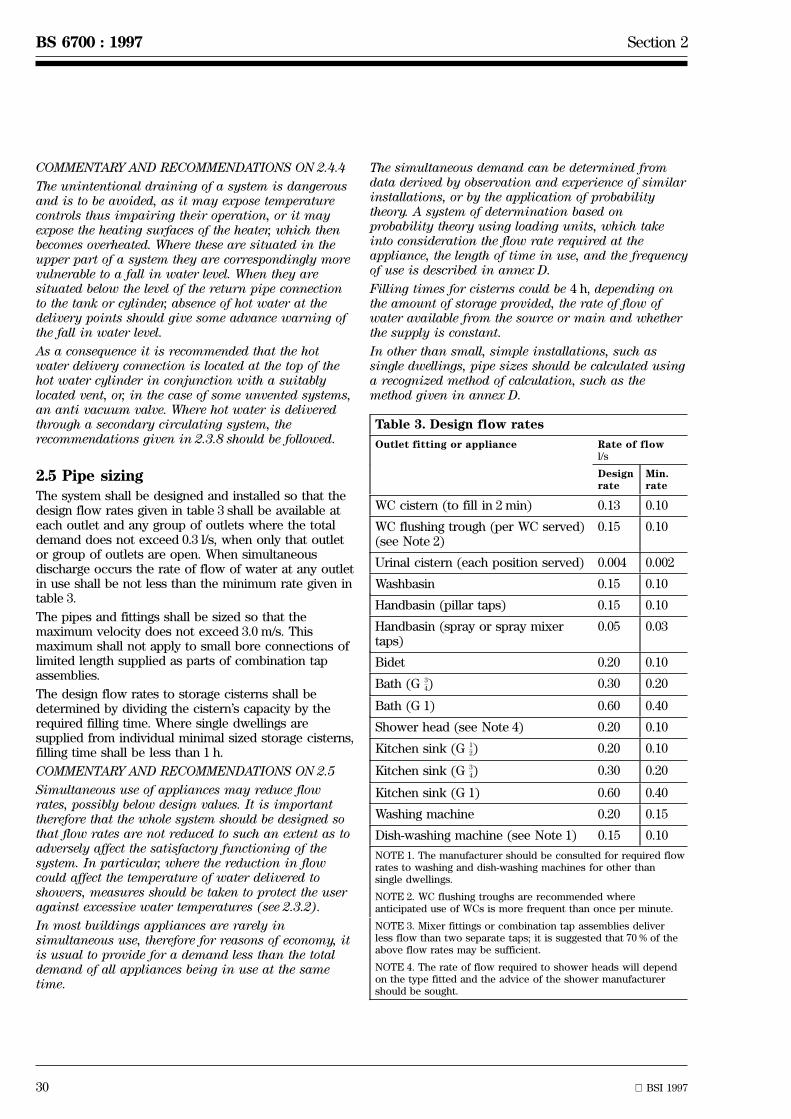
30 BSI 1997
BS 6700 : 1997 Section 2
COMMENTARY AND RECOMMENDATIONS ON 2.4.4
The unintentional draining of a system is dangerousand is to be avoided, as it may expose temperaturecontrols thus impairing their operation, or it mayexpose the heating surfaces of the heater, which thenbecomes overheated. Where these are situated in theupper part of a system they are correspondingly morevulnerable to a fall in water level. When they aresituated below the level of the return pipe connectionto the tank or cylinder, absence of hot water at thedelivery points should give some advance warning ofthe fall in water level.
As a consequence it is recommended that the hotwater delivery connection is located at the top of thehot water cylinder in conjunction with a suitablylocated vent, or, in the case of some unvented systems,an anti vacuum valve. Where hot water is deliveredthrough a secondary circulating system, therecommendations given in 2.3.8 should be followed.
2.5 Pipe sizingThe system shall be designed and installed so that thedesign flow rates given in table 3 shall be available ateach outlet and any group of outlets where the totaldemand does not exceed 0.3 l/s, when only that outletor group of outlets are open. When simultaneousdischarge occurs the rate of flow of water at any outletin use shall be not less than the minimum rate given intable 3.
The pipes and fittings shall be sized so that themaximum velocity does not exceed 3.0 m/s. Thismaximum shall not apply to small bore connections oflimited length supplied as parts of combination tapassemblies.
The design flow rates to storage cisterns shall bedetermined by dividing the cistern's capacity by therequired filling time. Where single dwellings aresupplied from individual minimal sized storage cisterns,filling time shall be less than 1 h.
COMMENTARY AND RECOMMENDATIONS ON 2.5
Simultaneous use of appliances may reduce flowrates, possibly below design values. It is importanttherefore that the whole system should be designed sothat flow rates are not reduced to such an extent as toadversely affect the satisfactory functioning of thesystem. In particular, where the reduction in flowcould affect the temperature of water delivered toshowers, measures should be taken to protect the useragainst excessive water temperatures (see 2.3.2).
In most buildings appliances are rarely insimultaneous use, therefore for reasons of economy, itis usual to provide for a demand less than the totaldemand of all appliances being in use at the sametime.
The simultaneous demand can be determined fromdata derived by observation and experience of similarinstallations, or by the application of probabilitytheory. A system of determination based onprobability theory using loading units, which takeinto consideration the flow rate required at theappliance, the length of time in use, and the frequencyof use is described in annex D.
Filling times for cisterns could be 4 h, depending onthe amount of storage provided, the rate of flow ofwater available from the source or main and whetherthe supply is constant.
In other than small, simple installations, such assingle dwellings, pipe sizes should be calculated usinga recognized method of calculation, such as themethod given in annex D.
Table 3. Design flow rates
Outlet fitting or appliance Rate of flowl/s
Designrate
Min.rate
WC cistern (to fill in 2 min) 0.13 0.10
WC flushing trough (per WC served)(see Note 2)
0.15 0.10
Urinal cistern (each position served) 0.004 0.002
Washbasin 0.15 0.10
Handbasin (pillar taps) 0.15 0.10
Handbasin (spray or spray mixertaps)
0.05 0.03
Bidet 0.20 0.10
Bath (G )3
4 0.30 0.20
Bath (G 1) 0.60 0.40
Shower head (see Note 4) 0.20 0.10
Kitchen sink (G )1
2 0.20 0.10
Kitchen sink (G )3
4 0.30 0.20
Kitchen sink (G 1) 0.60 0.40
Washing machine 0.20 0.15
Dish-washing machine (see Note 1) 0.15 0.10
NOTE 1. The manufacturer should be consulted for required flowrates to washing and dish-washing machines for other thansingle dwellings.
NOTE 2. WC flushing troughs are recommended whereanticipated use of WCs is more frequent than once per minute.
NOTE 3. Mixer fittings or combination tap assemblies deliverless flow than two separate taps; it is suggested that 70 % of theabove flow rates may be sufficient.
NOTE 4. The rate of flow required to shower heads will dependon the type fitted and the advice of the shower manufacturershould be sought.
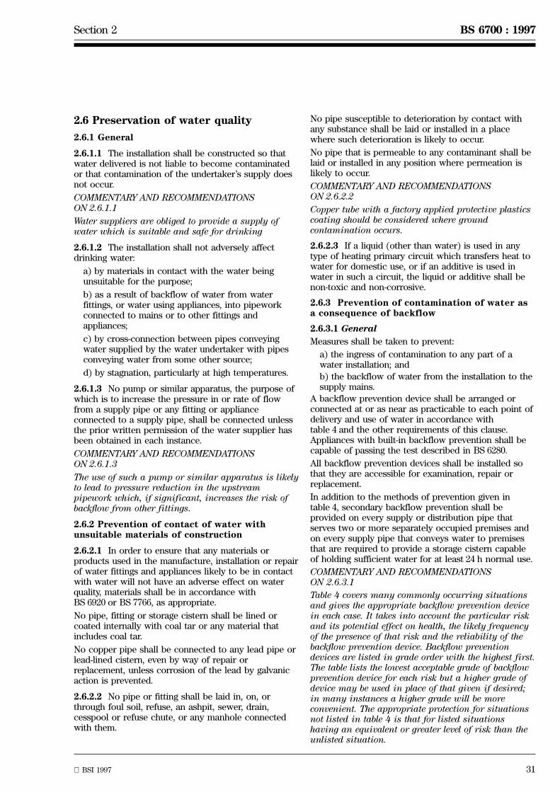
Section 2 BS 6700 : 1997
BSI 1997 31
2.6 Preservation of water quality
2.6.1 General
2.6.1.1 The installation shall be constructed so thatwater delivered is not liable to become contaminatedor that contamination of the undertaker's supply doesnot occur.
COMMENTARY AND RECOMMENDATIONSON 2.6.1.1
Water suppliers are obliged to provide a supply ofwater which is suitable and safe for drinking
2.6.1.2 The installation shall not adversely affectdrinking water:
a) by materials in contact with the water beingunsuitable for the purpose;
b) as a result of backflow of water from waterfittings, or water using appliances, into pipeworkconnected to mains or to other fittings andappliances;
c) by cross-connection between pipes conveyingwater supplied by the water undertaker with pipesconveying water from some other source;
d) by stagnation, particularly at high temperatures.
2.6.1.3 No pump or similar apparatus, the purpose ofwhich is to increase the pressure in or rate of flowfrom a supply pipe or any fitting or applianceconnected to a supply pipe, shall be connected unlessthe prior written permission of the water supplier hasbeen obtained in each instance.
COMMENTARY AND RECOMMENDATIONSON 2.6.1.3
The use of such a pump or similar apparatus is likelyto lead to pressure reduction in the upstreampipework which, if significant, increases the risk ofbackflow from other fittings.
2.6.2 Prevention of contact of water withunsuitable materials of construction
2.6.2.1 In order to ensure that any materials orproducts used in the manufacture, installation or repairof water fittings and appliances likely to be in contactwith water will not have an adverse effect on waterquality, materials shall be in accordance withBS 6920 or BS 7766, as appropriate.
No pipe, fitting or storage cistern shall be lined orcoated internally with coal tar or any material thatincludes coal tar.
No copper pipe shall be connected to any lead pipe orlead-lined cistern, even by way of repair orreplacement, unless corrosion of the lead by galvanicaction is prevented.
2.6.2.2 No pipe or fitting shall be laid in, on, orthrough foul soil, refuse, an ashpit, sewer, drain,cesspool or refuse chute, or any manhole connectedwith them.
No pipe susceptible to deterioration by contact withany substance shall be laid or installed in a placewhere such deterioration is likely to occur.
No pipe that is permeable to any contaminant shall belaid or installed in any position where permeation islikely to occur.
COMMENTARY AND RECOMMENDATIONSON 2.6.2.2
Copper tube with a factory applied protective plasticscoating should be considered where groundcontamination occurs.
2.6.2.3 If a liquid (other than water) is used in anytype of heating primary circuit which transfers heat towater for domestic use, or if an additive is used inwater in such a circuit, the liquid or additive shall benon-toxic and non-corrosive.
2.6.3 Prevention of contamination of water asa consequence of backflow
2.6.3.1 General
Measures shall be taken to prevent:
a) the ingress of contamination to any part of awater installation; and
b) the backflow of water from the installation to thesupply mains.
A backflow prevention device shall be arranged orconnected at or as near as practicable to each point ofdelivery and use of water in accordance withtable 4 and the other requirements of this clause.Appliances with built-in backflow prevention shall becapable of passing the test described in BS 6280.
All backflow prevention devices shall be installed sothat they are accessible for examination, repair orreplacement.
In addition to the methods of prevention given intable 4, secondary backflow prevention shall beprovided on every supply or distribution pipe thatserves two or more separately occupied premises andon every supply pipe that conveys water to premisesthat are required to provide a storage cistern capableof holding sufficient water for at least 24 h normal use.
COMMENTARY AND RECOMMENDATIONSON 2.6.3.1
Table 4 covers many commonly occurring situationsand gives the appropriate backflow prevention devicein each case. It takes into account the particular riskand its potential effect on health, the likely frequencyof the presence of that risk and the reliability of thebackflow prevention device. Backflow preventiondevices are listed in grade order with the highest first.The table lists the lowest acceptable grade of backflowprevention device for each risk but a higher grade ofdevice may be used in place of that given if desired;in many instances a higher grade will be moreconvenient. The appropriate protection for situationsnot listed in table 4 is that for listed situationshaving an equivalent or greater level of risk than theunlisted situation.
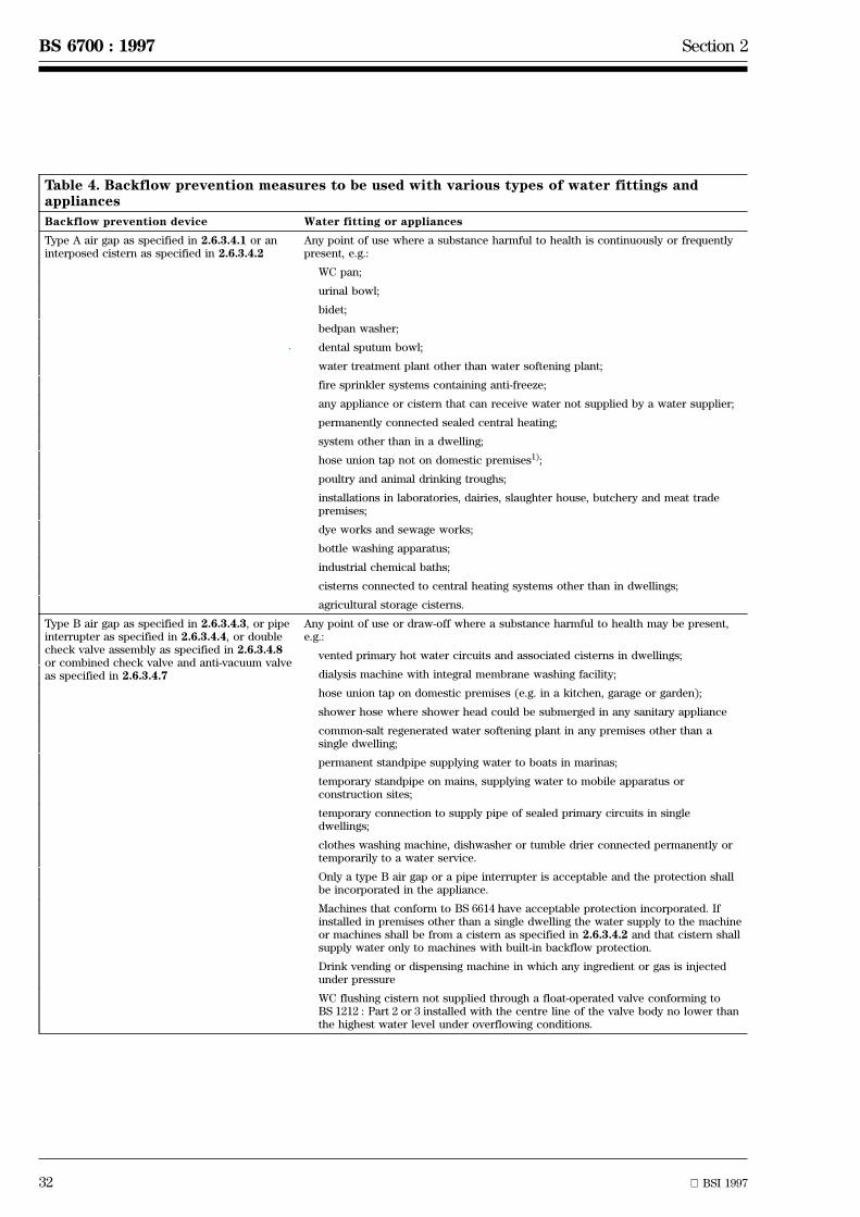
32 BSI 1997
BS 6700 : 1997 Section 2
Table 4. Backflow prevention measures to be used with various types of water fittings andappliances
Backflow prevention device Water fitting or appliances
Type A air gap as specified in 2.6.3.4.1 or aninterposed cistern as specified in 2.6.3.4.2
Any point of use where a substance harmful to health is continuously or frequentlypresent, e.g.:
WC pan;
urinal bowl;
bidet;
bedpan washer;
dental sputum bowl;
water treatment plant other than water softening plant;
fire sprinkler systems containing anti-freeze;
any appliance or cistern that can receive water not supplied by a water supplier;
permanently connected sealed central heating;
system other than in a dwelling;
hose union tap not on domestic premises1);
poultry and animal drinking troughs;
installations in laboratories, dairies, slaughter house, butchery and meat tradepremises;
dye works and sewage works;
bottle washing apparatus;
industrial chemical baths;
cisterns connected to central heating systems other than in dwellings;
agricultural storage cisterns.
Type B air gap as specified in 2.6.3.4.3, or pipeinterrupter as specified in 2.6.3.4.4, or doublecheck valve assembly as specified in 2.6.3.4.8or combined check valve and anti-vacuum valveas specified in 2.6.3.4.7
Any point of use or draw-off where a substance harmful to health may be present,e.g.:
vented primary hot water circuits and associated cisterns in dwellings;
dialysis machine with integral membrane washing facility;
hose union tap on domestic premises (e.g. in a kitchen, garage or garden);
shower hose where shower head could be submerged in any sanitary appliance
common-salt regenerated water softening plant in any premises other than asingle dwelling;
permanent standpipe supplying water to boats in marinas;
temporary standpipe on mains, supplying water to mobile apparatus orconstruction sites;
temporary connection to supply pipe of sealed primary circuits in singledwellings;
clothes washing machine, dishwasher or tumble drier connected permanently ortemporarily to a water service.
Only a type B air gap or a pipe interrupter is acceptable and the protection shallbe incorporated in the appliance.
Machines that conform to BS 6614 have acceptable protection incorporated. Ifinstalled in premises other than a single dwelling the water supply to the machineor machines shall be from a cistern as specified in 2.6.3.4.2 and that cistern shallsupply water only to machines with built-in backflow protection.
Drink vending or dispensing machine in which any ingredient or gas is injectedunder pressure
WC flushing cistern not supplied through a float-operated valve conforming toBS 1212 : Part 2 or 3 installed with the centre line of the valve body no lower thanthe highest water level under overflowing conditions.

Section 2 BS 6700 : 1997
BSI 1997 33
Table 4. Backflow prevention measures to be used with various types of water fittings andappliances (continued)
Backflow prevention device Water fitting or appliances
Check valve as specified in 2.6.3.4.6. Any point of delivery or use where a substance harmful to health is not or isunlikely to be present, e.g.:
common-salt regenerated water softener in single dwelling;
home dialysing machine without integral membrane washing facility;
fire sprinkler system without storage connected to a supply pipe;
drink vending or dispensing machine in which no ingredient or gas is injectedunder pressure.
1) Unless the fitting incorporates, as close as practicable to the point of use, a double check valve assembly or a combined check valveand anti-vacuum valve, and the fitting has been installed with written permission from the water supplier.
NOTE. A WC cistern supplied with water through a float-operated valve conforming to BS 1212 : Part 2 or 3 installed with the centreline of the valve body no lower than the highest water level under overflowing conditions normally requires no additionalback-siphonage protection.
34 BSI 1997
BS 6700 : 1997 Section 2
2.6.3.2 Delivery taps
Except where a tap draws water from a distributingpipe and the point of discharge is at the same level orlower than all other points of draw-off from thedistributing pipe, every other tap installed to dischargewater into a sink, washbasin, bath or similar fixedappliance shall:
a) be installed so that the vertical distance betweenthe point of discharge of the tap and the spill-overlevel of the receiving appliance is not less than thatindicated in table 6 for the size of fitting concerned;or
b) incorporate a double check valve assembly (see2.6.3.4.8); or
c) have fitted adjacent to the point of discharge adouble check valve assembly (see 2.6.3.4.8) or acombined check valve and anti-vacuum valve(see 2.6.3.4.7) installed with the anti-vacuum valveat least 300 mm above the spill-over level of thereceiving appliance.
2.6.3.3 Backflow prevention for bidets
2.6.3.3.1 Bidets of the over-rim water feed type thatdo not incorporate an ascending spray may beconnected to a supply pipe providing that:
a) the vertical distance between the lowest part ofthe outlet of the taps or mixer supplying water tothe bidet, and the spill-over level of the bidet, is notless than that shown in table 5 for the appropriatesize of fitting; and
b) they are so designed, installed and arranged thatno hose or hand-held flexible spray is attached tothe water inlet fittings.
2.6.3.3.2 Bidets that do not conform to 2.6.3.3.1 shallbe supplied with:
a) both hot and cold supplies through a type A airgap or an interposed cistern (2.6.3.4.2) supplyingonly the bidet; or
b) cold water from a distributing pipe from which,other than a WC or urinal flushing cistern, no otherappliance located below the spill-over level of thebidet is served; or
c) hot water from a vented hot water distributingpipe that supplies hot water to no other draw-offpoint located below the spillover level of the bidet,unless the hot water pipe that supplies the bidetincludes a check valve installed downstream of avented hot water distributing pipe, and incorporatesa 300 mm vertical offset drop to the bidet.
Table 5. Air gaps at taps
Nominal size of tap or fitting Minimum verticaldistance between tapoutlet and spill-overlevel of receivingappliancemm
Up to and including size1
220
Over size up to and including1
2
size3
4
25
Over size3
470
NOTE. Size and size taps to BS 5412 and size taps to1
2
3
4
1
2
BS EN 200 will normally provide the required gap.
2.6.3.4 Backflow prevention devices
2.6.3.4.1 Type A air gap
A type A air gap shall conform to BS 6281 : Part 1.
2.6.3.4.2 Interposed cistern
Interposed cisterns shall be installed so that thefollowing criteria are conformed to:
a) each feed to the cistern shall only be through afloat-operated valve conforming to BS 1212 :Part 2 or 3 mounted with its body horizontal centreline no lower than the highest water level underoverflowing conditions; or
b) each feed to the cistern shall be protected by atype B air gap, pipe interrupter or a double checkvalve assembly.
In addition, in each of the above cases:
1) the cistern shall conform to all other relevantrequirements of this standard (in particularsee 2.2.3.1);
2) outflow from the cistern shall be by gravityonly;
3) the spill-over level of every vessel situateddownstream of the cistern shall be not lessthan 300 mm vertically below the invert level ofthe warning pipe of the cistern;
4) the lowest point of the inside base of thecistern shall be not less than 15 mm above thespill-over level of any vessel situateddownstream of the cistern.
Section 2 BS 6700 : 1997
BSI 1997 35
2.6.3.4.3 Type B air gap
Every type B air gap shall conform to BS 6281 : Part 2.
COMMENTARY AND RECOMMENDATIONSON 2.6.3.4.3
Float operated valves manufactured in accordancewith BS 1212 : Part 2 or 3 may satisfy therequirements of a type B air gap when installed incisterns where the axis of the valve (or the centrepoint of the interface between the seat and seatingmember in any valve where the axis of the seat is nothorizontal) is on the same horizontal plane as theaxis of the warning pipe.
2.6.3.4.4 Pipe interrupter
Every pipe interrupter shall conform to BS 6281 :Part 3.
Pipe interrupters shall be installed so that:
a) no tap or valve is installed downstream of thepipe interrupter;
b) the minimum diameter of the waterwaydownstream of the pipe interrupter, until a freedischarge is reached, is not less than that of a pipeof the nominal size as the pipe interrupter;
c) the length of pipe downstream of the pipeinterrupter is as short as is practicable, consistentwith the requirement in d);
d) it is readily accessible for inspection.
2.6.3.4.5 Anti-vacuum valve
Anti-vacuum valves shall conform to BS 6282 :Part 2 or 3.
Each anti-vacuum valve shall be installed at a height ofnot less than 150 mm above the overflowing level ofthe receiving cistern, vessel or appliance, when thelatter is fixed, or not less than 300 mm above the outletof the fitting in all other cases.
No control valve, e.g. a tap, shall be installeddownstream of an atmospheric in-line anti-vacuumvalve. Provision for conducting away any water spilledfrom the device shall be installed with every pressuretype anti-vacuum valve but is optional with anatmospheric type.
Where a check valve is arranged and connected inassociation with and adjacent to an anti-vacuum valve,the check valve shall be located upstream of theanti-vacuum valve.
NOTE. In such cases no minimum vertical distance between thecheck valve and the overflowing level of the receiver or outlet ofthe draw-off fitting is specified.
COMMENTARY AND RECOMMENDATIONSON 2.6.3.4.5
Every anti-vacuum valve should be of the samenominal size as the pipe to which it is connected.
2.6.3.4.6 Check valve
Every check valve backflow prevention device shallconform to BS 6282 : Part 1.
2.6.3.4.7 Combined check valve and anti-vacuumvalve
Where no control valve is installed downstream, everycombined check valve and anti-vacuum valve shall beconstructed and installed in accordance with BS 6282 :Part 4, and the anti-vacuum component of the valveshall admit air to the downstream pipework. Where acontrol valve is installed downstream, every combinedcheck valve and anti-vacuum valve shall in additionhave a pressure type anti-vacuum elementincorporated.
2.6.3.4.8 Double check valve or double check valveassembly
A double check valve or double check valve assemblyshall comprise two check valves with a test portlocated between them.
The check valve elements of every double check valveor double check valve assembly shall conform toBS 6282 : Part 1.
2.6.3.5 Secondary backflow protection of supplypipes
Secondary backflow protection shall be provided in thefollowing cases:
a) on a common supply pipe serving two or moreseparately occupied premises (at each premises);and
b) on a supply pipe which conveys water topremises receiving an intermittent supply (forexample, where section 60, Schedule III, WaterAct 1945, applies [see A.2.1]).
Where a secondary backflow protection of supplypipes is required, this shall be constructed andarranged as illustrated in figure 9.
A double check valve assembly that conformsto 2.6.3.4.8 shall be installed at each junction of thesupply pipe and the branch pipe.
COMMENTARY AND RECOMMENDATIONSON 2.6.3.5
It may prove convenient for each double check valveassembly to be installed immediately downstream of,or in combination with, the stopvalve (if provided).
Secondary backflow protection may be of value withina single premises (such as an office block on severalfloors) as a means of reducing internalcontamination as a consequence of vandalism or lackof maintenance (see figure 9).

36 BSI 1997
BS 6700 : 1997 Section 2
Ceiling
Ceiling
Ceiling of flat
Double check valve assembly for secondary backflow prevention at each flat
Supplystopvalve
Supplypipe
Figure 9. Example of secondary backflow protection of supply pipes
2.6.3.6 Secondary backflow protection fordistributing pipes
Secondary backflow protection shall be provided oncommon distributing pipe systems serving two or moreseparately occupied premises.
Where secondary backflow prevention is required incistern-fed systems, this shall be arranged using one ofthe following methods (see figure 10).
a) A vent pipe shall be connected and arranged oneach distributing pipe at its junction with the storagecistern. Every such vent and distributing pipe shallbe of the same size as the distributing pipe at itspoint of connection to the cistern.
In addition, except for a fixed appliance that has itsoverflowing level at the lowest elevation within thedistributing pipe system, every water fitting orappliance shall only be connected to a falling lengthof distributing pipe by means of a branch pipe, nopart of which shall be at a higher level than thepoint of its junction with the said distributing pipe.
Every such branch pipe shall be arranged so that theoverflowing level of any fixed appliance served by adraw-off fitting connected to that branch pipe is notless than 300 mm below the point where the branchpipe is connected to the distributing pipe.
b) A double check valve assembly that conforms to2.6.3.4.8 shall be installed at each junction of therising or falling distributing pipe and a branch pipe.
COMMENTARY AND RECOMMENDATIONSON 2.6.3.6
It may prove convenient for each double check valveassembly to be installed immediately downstream of,or in combination with, the stopvalve (if provided).
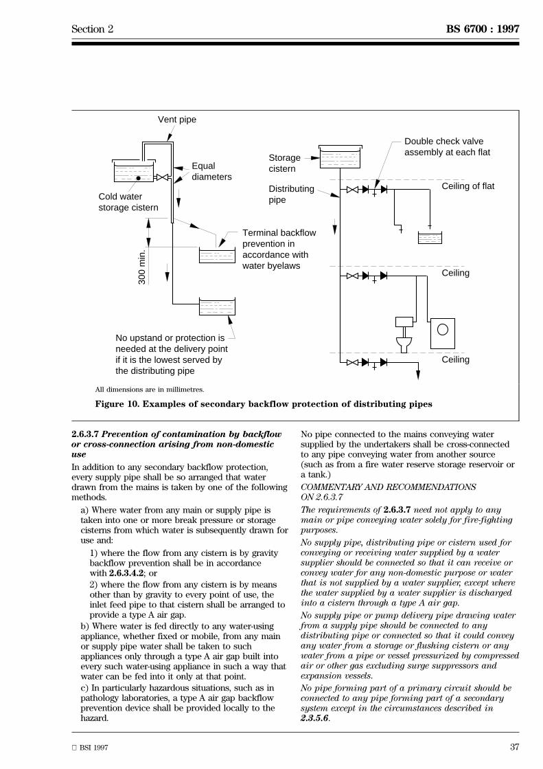
Section 2 BS 6700 : 1997
BSI 1997 37
Ceiling
Ceiling
Ceiling of flatDistributingpipe
Storagecistern
Double check valve assembly at each flat
Vent pipe
Equaldiameters
Cold waterstorage cistern
Terminal backflowprevention inaccordance withwater byelaws
No upstand or protection is needed at the delivery point if it is the lowest served by the distributing pipe
300
min
.
All dimensions are in millimetres.
Figure 10. Examples of secondary backflow protection of distributing pipes
2.6.3.7 Prevention of contamination by backflowor cross-connection arising from non-domesticuse
In addition to any secondary backflow protection,every supply pipe shall be so arranged that waterdrawn from the mains is taken by one of the followingmethods.
a) Where water from any main or supply pipe istaken into one or more break pressure or storagecisterns from which water is subsequently drawn foruse and:
1) where the flow from any cistern is by gravitybackflow prevention shall be in accordancewith 2.6.3.4.2; or
2) where the flow from any cistern is by meansother than by gravity to every point of use, theinlet feed pipe to that cistern shall be arranged toprovide a type A air gap.
b) Where water is fed directly to any water-usingappliance, whether fixed or mobile, from any mainor supply pipe water shall be taken to suchappliances only through a type A air gap built intoevery such water-using appliance in such a way thatwater can be fed into it only at that point.
c) In particularly hazardous situations, such as inpathology laboratories, a type A air gap backflowprevention device shall be provided locally to thehazard.
No pipe connected to the mains conveying watersupplied by the undertakers shall be cross-connectedto any pipe conveying water from another source(such as from a fire water reserve storage reservoir ora tank.)
COMMENTARY AND RECOMMENDATIONSON 2.6.3.7
The requirements of 2.6.3.7 need not apply to anymain or pipe conveying water solely for fire-fightingpurposes.
No supply pipe, distributing pipe or cistern used forconveying or receiving water supplied by a watersupplier should be connected so that it can receive orconvey water for any non-domestic purpose or waterthat is not supplied by a water supplier, except wherethe water supplied by a water supplier is dischargedinto a cistern through a type A air gap.
No supply pipe or pump delivery pipe drawing waterfrom a supply pipe should be connected to anydistributing pipe or connected so that it could conveyany water from a storage or flushing cistern or anywater from a pipe or vessel pressurized by compressedair or other gas excluding surge suppressors andexpansion vessels.
No pipe forming part of a primary circuit should beconnected to any pipe forming part of a secondarysystem except in the circumstances described in2.3.5.6.
38 BSI 1997
BS 6700 : 1997 Section 2
2.6.4 Prevention of contamination of drinkingwater by legionella
Measures shall be taken in the design and installationof cold and hot water systems to prevent thecolonization of the system with legionella. These shallinclude the avoidance of:
a) stagnation of water in pipes, cisterns and otherstorage vessels;
b) water temperatures dwelling in the range of 20 ÊCto 45 ÊC;
c) use of materials that can harbour or providenutrient for bacteria and other organisms;
d) installation of fittings where there is a potentialfor aerosol formation.
COMMENTARY AND RECOMMENDATIONS ON 2.6.4
Good practice is assumed if the recommendationscontained in the Approved Code of Practice L8(rev)[3], and the Health and Safety Executive's bookletHS(G)70 [4] together with the other guidancedocuments [2,5,6] listed in the list of references, arefollowed.
The code of practice draws particular attention to:
a) hot water services where the volume of hot waterin the system exceeds 300 l; and
b) cold and hot water services irrespective of size inpremises where occupants are particularlysusceptible, such as health care premises.
In order to reduce the risk of colonization of a watersystem the temperature of cold water in pipes andcisterns should not exceed 20 ÊC, and hot water shouldbe stored and distributed at a temperature of not lessthan 60 ÊC with a temperature at the discharge pointof 50 ÊC after 1 min.
Cold and hot water pipework should be as short aspracticable, especially where it only servesinfrequently used taps and fittings.
2.7 Maintenance of water temperaturewithin the system
2.7.1 General
Installations shall be protected against conditionsarising from adverse temperatures external to pipes,fittings and appliances. Protection shall be providedagainst:
a) ice formation in pipework and fittings;
b) heating of cold supply pipes;
c) condensation.
Where the placing of pipes and fittings above groundoutside buildings is unavoidable, these pipes andfittings shall be protected by insulation with aweatherproof finish, in accordance with 2.7.3. Wherepipes rise from the ground, the insulation shall extendto the depth below ground stated in 2.7.3.
COMMENTARY AND RECOMMENDATIONS ON 2.7.1
Suitable precautions or protection methods whichneed to be taken to reduce the risk of bursting,interruption of supply, waste, leakage and consequentdamage to the building are the provision of:
a) insulation;
b) trace heating tapes; or
c) local heating.
In winter, water may only just be above freezing pointwhen delivered into the consumer's pipes and afurther reduction in temperature could cause freezing.Particularly vulnerable locations which requireprotection include those where flow is very slow,infrequent or through small diameter pipes.
To prevent freezing of water services in buildings it ispreferable to keep the inside of the buildingcontinuously warm by the provision andmaintenance of adequate heating. When the wholebuilding is not heated, or where heating is onlyintermittent, heating of water pipes and fittings(trace heating) or heating their immediatesurroundings (local heating) may suffice.
The layout of the water service should be planned toavoid the following:
a) external locations above ground;
b) unheated spaces;
c) positions near a window, air brick or otherventilator, external door or any other place wherecold draughts are likely to occur;
d) a chase or duct formed in an external wall.
Care should be taken in the control of temperatureswhere trace heating is installed with plastics pipes.
2.7.2 Protection of water pipes and fittings
2.7.2.1 Underground pipes
Pipes laid underground outside buildings and notinsulated in accordance with 2.7.3 shall be laid at adepth sufficient to give protection against freezing andno less than 0.75 m (see figure 11 and 2.1.8).
COMMENTARY AND RECOMMENDATIONSON 2.7.2.1
Underground stopvalves should not be brought up to ahigher level merely for ease of access.
2.7.2.2 Pipes entering buildings
Where pipes rise from below the ground, theinsulation shall extend to at least 0.75 m below theground, in accordance with 2.7.3. (See figure 11,3.1.6.2 and 2.8.2).
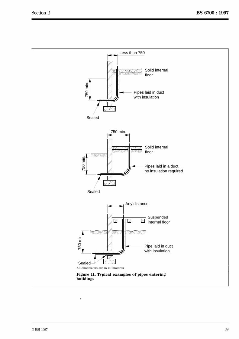
Section 2 BS 6700 : 1997
BSI 1997 39
������ Solid internal
floor
Pipes laid in ductwith insulation
Sealed
750
min
.
Less than 750
Solid internalfloor
Pipes laid in a duct,no insulation required
Sealed
750
min
.
750 min.
������ Suspended
internal floor
Pipe laid in ductwith insulation
Sealed
750
min
.
Any distance
All dimensions are in millimetres.
Figure 11. Typical examples of pipes enteringbuildings

40 BSI 1997
BS 6700 : 1997 Section 2
Table 6. Calculated minimum thickness of insulation to protect copper pipes fixed inside premisesfor domestic cold water systems.
Outsidediameter
Inside diameter(bore)
Thermal conductivity at 0 ÊCW/(m´K)
0.025 0.035 0.045 0.055
Thickness of insulation
mm mm mm
15 13.6 30 62 124 241
22 20.2 12 20 30 43
28 26.2 8 12 17 23
35 32.6 6 9 12 15
42 39.6 5 7 9 11
Table 7. Calculated minimum thickness of insulation to protect copper pipes fixed inside premisesagainst freezing for commercial and institutional applications1)
Outsidediameter
Inside
diameter
(bore)
Thermal conductivityW/(m´K)
0.025 0.035 0.045 0.055
Thickness of insulation
mm mm mm
15.0 13.6 31 56 83 109
22.0 20.2 13 21 31 45
28.0 26.2 8 13 18 24
35.0 32.6 7 9 13 16
42.0 39.6 5 7 9 12
54.0 51.6 4 5 7 8
76.1 73.1 3 4 5 6
108.0 105.0 2 3 3 4
Above 108.0 mm outside diameterand flat surfaces
2 3 3 4
1)Water temperature, +5 ÊC; ambient temperature, 23 ÊC; evaluation period, 24 h; permitted ice formation 50 %.
2.7.2.3 Pipes and fittings inside buildings
Pipes and fittings shall be insulated in accordance with2.7.3.
Insulation shall be provided on the top and sides ofany cistern.
COMMENTARY AND RECOMMENDATIONSON 2.7.2.3
Where pipes are attached to the inside faces ofexternal walls in a part of a building that is heated, itshould not be necessary to insulate them, but it isadvantageous to fix such pipes clear of the wall onbrackets or clipped to a pipe board.
Cold water pipes should be protected to prevent theformation of condensation. Where cold water pipespass through areas of relatively high humidity,condensation will form unless prevented. Insulation,as a measure of prevention of condensation, is subjectto the same requirements as insulation against heatloss or gain (see 2.7.3).
2.7.3 Insulation
Thermal insulating materials shall conform toBS 5422 and shall be installed in accordance withBS 5970.
The minimum thickness of thermal insulating materialsused for the protection of water pipes and fittings shallbe as given in tables 6 and 7.
Where cold water pipes pass through areas ofrelatively high dew point, they shall be insulated toprevent condensation.
Section 2 BS 6700 : 1997
BSI 1997 41
COMMENTARY AND RECOMMENDATIONS ON 2.7.3
Insulation slows down but does not prevent loss ofheat from the water. Insulation will not give completeprotection if the temperature falls to or below freezingpoint. However, a suitable thickness of insulation willdelay the onset of freezing.
The thickness of insulating materials specified inBS 5422, whilst giving protection, is not consideredpracticable for protection of small diameter pipesfixed inside buildings. However, the thickness ofinsulating material identified in table 6, under theappropriate thermal conductivity values, isconsidered practicable and suitable for small diameterpipework and will provide reasonable protection forpipes fixed inside normally occupied buildings.
Unless the insulation material used is itselfsufficiently impermeable to water vapour, a vapourbarrier with a permeance not exceeding 0.05 g/(s MN)should be applied on the outside surface of theinsulation and protected against damage if necessary.
Table 8. Examples of insulating materials
Thermal conductivity
W/(m´K)
Material
Less than 0.020 Rigid phenolic foam
0.021 to 0.035 Polyurethane foam
0.040 to 0.055 Corkboard
0.055 to 0.07 Exfoliated vermiculite
(loose fill)
2.7.4 Local and trace heating
Electric trace heating shall conform to BS 6351 : Part 1.
Any trace heating provided for the protection of anypipes or fittings shall be additional to, and not insubstitution for insulation referred to in 2.7.
COMMENTARY AND RECOMMENDATIONS ON 2.7.4
Local heating, in conjunction with a frost-thermostat,should only be used where other methods of frostprotection are unsuitable, e.g. for pipes in unheatedroof spaces when it is inconvenient to drain them andthe building is to be unheated for a period during thewinter.
Where trace heating is provided, it should be fittedbefore the insulation is applied.
2.7.5 Drainage of system to prevent frostdamage
Arrangements shall be provided for isolating anddraining pipes and fittings (see 2.2.5 to 2.2.7).
Where a building is divided into parts the pipes andfittings in each part shall be arranged so that they maybe isolated and drained without affecting the supply toany other part. Stopvalves shall be located in positionsconvenient for use as close as practicable to the pointof entry of the pipe into the building or part thereof.Unless the stopvalve is installed within a normallyheated building it shall be protected against freezing inaccordance with 2.7.1 to 2.7.4.
Every external standpipe, livestock watering appliance,garden tap, garage tap, or similar water fitting shall besupplied through a stopvalve which is located in aposition convenient for use within a normally heatedbuilding or is protected against freezing in accordancewith 2.7.
The pipes and fittings in any part of a building notused in winter, any unheated building or part of abuilding, including any water-closet, garage orconservatory, or any other outbuilding, shall bearranged so as to enable them to be isolated anddrained separately.
2.8 Accessibility of pipes and waterfittings
2.8.1 General
The design of a system shall allow ready access topipes and fittings for the purposes of inspection,maintenance and replacement (see figure 12).
COMMENTARY AND RECOMMENDATIONS ON 2.8.1
Other factors that may be considered are:
a) The use to which the building is to be put:importance of aesthetic considerations;consequences of leakage from inaccessible parts ofthe pipework; whether or not the system will besubject to routine inspection and maintenance.
b) The increase or decrease in capital ormaintenance costs arising from the provision ofimproved accessibility: ease of forming ducts orchases; changes to pipe runs; ease of provision ofremovable access panels or covers; availability ofmulti-service walkways or crawlways in whichwater pipes may be installed.
c) The pipework materials and jointing methods:reliability of joints; resistance to both internal andexternal corrosion; flexibility of pipe when insertedin curved ducts or sleeves.
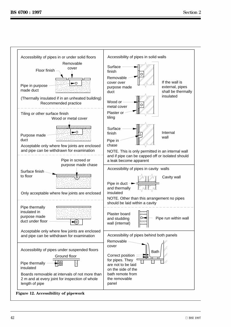
42 BSI 1997
BS 6700 : 1997 Section 2
���
��
������
�
����
Removablecover
Floor finish
Pipe in purposemade duct
Purpose made duct
Wood or metal cover
Ground floor
Pipe thermallyinsulated
Pipe thermallyinsulated inpurpose madeduct under floor
Internalwall
Surfacefinish
Wood or metal cover
Plaster ortiling
Surfacefinish
Removablecover overpurpose madeduct
Cavity wall
Pipe run within wall
Pipe in ductand thermallyinsulated
����
���
Pipe in chase
If the wall isexternal, pipesshall be thermallyinsulated
Plaster boardand studdingwall (internal)
Removablecover
Correct position for pipes. Theyare not to be laidon the side of thebath remote fromthe removablepanel
Pipe in screed orpurpose made chase
Surface finishto floor
Accessibility of pipes in solid wallsAccessibility of pipes in or under solid floors
Tiling or other surface finish
(Thermally insulated if in an unheated building)
Accessibility of pipes under suspended floors
Accessibility of pipes in cavity walls
Accessibility of pipes behind both panels
Boards removable at intervals of not more than2 m and at every joint for inspection of wholelength of pipe
Acceptable only where few joints are enclosedand pipe can be withdrawn for examination
Acceptable only where few joints are enclosedand pipe can be withdrawn for examination
Only acceptable where few joints are enclosed
NOTE. This is only permitted in an internal wall and if pipe can be capped off or isolated should a leak become apparent
NOTE. Other than this arrangement no pipesshould be laid within a cavity
Bath
Recommended practice
����
����
����
Figure 12. Accessibility of pipework

Section 2 BS 6700 : 1997
BSI 1997 43
2.8.2 Pipes passing through walls and floors
2.8.2.1 No pipe shall be installed in the cavity of anexternal cavity wall. Where a pipe passes through anywall or floor, there shall be adequate provision formovement of the pipe relative to the wall or floor, bythe use of a sleeve properly bonded into the wall orfloor or by other no less suitable means. (See also3.1.6.2.)
2.8.2.2 Where fire regulations and otherconsiderations require the ends of sleeves to be sealed,such sealing shall be of a permanently flexible form toallow movement of the pipe.
2.8.2.3 Where a pipe passes into a building it shall bearranged so as to accommodate differential movementand shall be accessible for withdrawal andreplacement. Where a sleeve is used for this purpose, itshall be capable of resisting external loading and shallbe sealed at each end in accordance with 2.8.2.2. Thediameter of the sleeve and the radius of any bendstherein shall be such as to permit the ready insertionand withdrawal of the pipe (see figure 11).
2.8.2.4 No sleeve intended for carrying a water pipeshall contain within it any other pipe.
2.8.2.5 Pipes and pipe joints enclosed in apurpose-made chase in any external wall or locatedunder a suspended floor at ground level or enclosedwithin a purpose-made sleeve or duct under any solidfloor shall, where necessary, be wrapped,plastics-coated or otherwise protected from freezing,corrosion and thermal movement.
2.8.2.6 All pipes laid in ducts shall be adequatelysupported by fixing in accordance with 3.1.7.2.
2.8.3 Underground stopvalves
stopvalves installed on an underground pipe shall beenclosed within a pipe guard or chamber under asurface box of the appropriate grade for the trafficloading according to the location (see BS 5834 : Part 2).
2.8.4 Accessibility of above ground valves
Every valve, including any backflow prevention device,shall be so placed that it is readily accessible forexamination, maintenance and operation by the meansby which it is designed to be operated. Any coversshall be fixed by removable fastenings.
2.8.5 Cisterns
Every storage cistern shall be so placed and equippedthat the interior thereof can be inspected and cleansedand the float-operated valve can be maintained, as infigure 13. For this purpose a clear space of not lessthan 350 mm shall be provided between the top of thecistern and any ceiling or other obstruction above thecistern. In the case of small cisterns the overheadunobstructed space may be reduced to 225 mmprovided no dimension of the cistern exceeds 450 mmin any plane.

44 BSI 1997
BS 6700 : 1997 Section 2
Hotcistern
Hotcistern
Coldcistern
Coldcistern
Hot
cis
tern
Col
d ci
ster
n
Hotcistern
350 max.
350
min
.
350
min
.
350
min
.
350
min
.
350 max.
1140
min
.
Handhole
Up to 1000 L
350
min
.
500
min
.
225
min
.
225
min
.X
X
X
X
X
XA B
Greater than 1000 L
a) Conventionallyshaped cistern
c) Large capacity cistern with bolted-on lid
b) Plumbing units
d) Hot water storage combination units
Dimension X should not be greater than 450NOTE. A provides access to float valve B provides access for inspection
NOTE. Acceptable sizes and positions of handholes are givenin clause 3 of BS 3198 : 1981
Coldcistern
All dimensions are in millimetres
Figure 13. Clear space needed above storage cisterns
Section 2 BS 6700 : 1997
BSI 1997 45
2.9 Water economy and energyconservation
2.9.1 General
The designer shall consider the water usage andenergy costs of an installation and seek to minimizethese, taking into account the requirements andrecommendations of 2.9.2 for water usage and 2.9.3for energy costs.
COMMENTARY AND RECOMMENDATIONS ON 2.9.1
Working pressure should be limited to the necessarymaximum.
BS 6465 : Part 1 gives guidance on the selection ofsanitary appliances and installations and should beconsidered in conjunction with the requirements andrecommendations of 2.9.2.
2.9.2 Water economy
2.9.2.1 Leakage
Warning pipes from cisterns and discharge pipes fromrelief valves shall be located so that any discharge willbe readily observed.
2.9.2.2 WC flushing
Every WC pan shall satisfy the flushing requirements ofBS 5503 : Part 2 when used with the flushing apparatusinstalled.
COMMENTARY AND RECOMMENDATIONSON 2.9.2.2
Attention is drawn to the water byelaws with respectto the arrangement of WC flushing (see A.2).
The discharge of the flushing apparatus should berelated to the design of the pan and arbitraryreduction in the flush is not recommended.
2.9.2.3 Urinal flushing
Every urinal shall be flushed with water supplied by anautomatic flushing cistern which incorporates siphonicapparatus.
Any cistern serving two or more urinal bowls or urinalslab positions shall be filled with water at a rate notexceeding 7.5 l/h per bowl or 700 mm width of urinalslab.
A cistern serving a single urinal shall be filled withwater at a rate not exceeding 10 l/h.
COMMENTARY AND RECOMMENDATIONSON 2.9.2.3
In lightly used installations, a user operated oractuated flush for individual stalls or bowls may befitted and will show a water saving if each unit isused less frequently than the automatic flushing rate.
2.9.2.4 Waste plugs
Every waste outlet from a bath (other than a showerbath or shower tray), washbasin, sink or similarappliance shall be provided with a well-fitting plug andretaining chain, pop-up plug or an equally effectiveclosure, except where the water supply is only by wayof a fitting incapable of supplying water at a rateexceeding 3.6 l/min per appliance or per washingtrough unit (see 2.9.2.6), or the appliance is formedical, dental or veterinary use and is intended to beused with an unplugged waste.
2.9.2.5 Self-closing taps
Self-closing taps shall be non-concussive in operationand shall close against the prevailing water pressurewithout leakage.
COMMENTARY AND RECOMMENDATIONSON 2.9.2.5
These taps are effective in preventing waste or undueconsumption. They should, however, only be usedwhere regular inspection and maintenance can beensured.
2.9.2.6 Washing troughs and fountains
The fitting or fittings delivering water to a washingtrough or fountain shall be capable of discharging toany one unit of the appliance without at the same timedischarging to any other. A unit is taken to mean alength of not more than 600 mm of a straight trough orof the outer edge of a round appliance.
2.9.2.7 Spray taps and aerators
Spray taps and aerators shall be regularly maintained
COMMENTARY AND RECOMMENDATIONSON 2.9.2.7
Spray taps may save as much as 50 % in both waterconsumption and fuel. The spray is only suitable forhand-rinsing and spray taps should not be used insituations where there may be heavy fouling of basinsby grease and dirt. Without regular attention, thespray head is likely to become blocked over a period oftime with any quality of water, but more particularlywith hard water. Since self-cleansing velocities canrarely be satisfactorily achieved, particularly in longdischarge pipes, blockage due to a build-up of greaseand soap residue tend to occur, especially in softwater areas. Particularly good performances havebeen reported from areas with water in the rangeof 100 mg/l to 135 mg/l total hardness.
Aerators, although intended for the purpose ofimproving the flow pattern, may also reduceconsumption by reducing the flow.
46 BSI 1997
BS 6700 : 1997 Section 2
2.9.3 Energy conservation
2.9.3.1 Hot water storage
With the exception of certain solid fuel appliances, allhot water storage systems shall be fitted with athermostat to control the maximum water temperature.
All pipes forming part of a primary or a secondarycirculation system for supplying domestic hot waterand all pipes carrying hot water to a tap or otheroutlet that are longer than the maximum length givenin table 9, shall be thermally insulated in accordancewith BS 5422, or so that the energy loss under normaloperating conditions at no time exceeds the valuesgiven in table 10.
Table 9. Maximum recommended lengths ofuninsulated hot water pipes
Outside diameter of pipe Maximumlength
mm m
12 20
Over 12 up to and including 22 12
Over 22 up to and including 28 8
Over 28 3
Table 10. Maximum permitted rates of energyloss from pipes
Outside diameter of pipe1) Maximumenergy loss
mm W/m2
10 675
20 400
30 280
40 220
50 and above 1751) For intermediate values of pipe diameter, the correspondingmaximum energy loss is found by interpolation.
COMMENTARY AND RECOMMENDATION ON 2.9.3.1
The need to restrict the length of hot waterdistributing pipes is considered in 2.3.8..
If trace heating is used, it should be of the electricself-regulating type specifically formulated fordomestic hot water systems. The system shouldconform to BS 6351.
Reducing the quantity and temperature of hot waterheated and/or stored to those necessary to meetrequirements will produce energy savings in additionto those achieved by insulation and controls. Storagevessels should therefore be sized to meet requirementswithout excessive over-capacity and considerationshould be given to fitting devices, such as doubleelement or twin electric immersion heaters ormanually controlled economy valves on directly heatedgas circulator systems, which enable a reducedquantity of water to be heated when desired.
2.9.3.2 Pumping of cold water
The energy cost of pumping shall be minimized bymaking prudent use of mains water pressure inconsultation with the water supplier. Permission toinstall a pump on a supply pipe shall be obtained fromthe water supplier.
COMMENTARY AND RECOMMENDATIONSON 2.9.3.2
Where mains pressure is insufficient to supply theupper floors of a building, mains supply to the lowerfloors without pumping should be considered.
BS 6700 : 1997
BSI 1997 47
Section 3. Installation
3.1 Work on site
3.1.1 Handling of materials
3.1.1.1 General
All materials and components used for theconstruction of a water system shall be handled withsufficient care and attention to prevent theirdeterioration. Such deterioration may impair theirserviceability or affect the performance of the system.
COMMENTARY AND RECOMMENDATIONSON 3.1.1.1
Some pipes are manufactured from asbestos cement.Work on these pipes, in common with work on allasbestos containing materials, is subject to theControl of Asbestos at Work Regulations and theoverriding duty to keep exposure to asbestos dust aslow as is reasonably practicable. Asbestos cementpipes contain about 10 % white asbestos and may alsocontain 1 % brown asbestos. These pipes are generallysafe to handle, but great care should be exercised incutting and grinding operations to keep dustgenerated to the minimum and prevent peoplebreathing in the dust. This may be achieved by theuse of damping down and using hand rather thanpower tools. If in doubt, guidance should be soughtfrom the Health and Safety Executive.
Manufacturers' advice should be followed concerninghow their products should be loaded, transported,unloaded and stored. Pipes, fittings and componentsin any material should be handled carefully to reducedamage.
3.1.1.2 Bending of pipes
Damaged pipes shall be rejected.
COMMENTARY AND RECOMMENDATIONSON 3.1.1.2
Care should be taken to avoid crimping andrestricting the diameter of pipes when forming bends.Purpose-designed equipment should be used whereappropriate.
3.1.2 Joining of pipes
3.1.2.1 General
All proprietary joints shall be made in accordance withthe manufacturer's instructions. Care shall be taken toestablish satisfactory jointing techniques for all waterservice pipework. When making joints by welding,brazing or soldering, precautions shall be taken toavoid the risk of fire, and care taken to avoidinhalation of fumes from the jointing process. All burrsshall be removed from the ends of pipes and anyjointing materials used shall be prevented fromentering the system. All piping and fittings shall becleaned internally and shall be free from particles ofsand, soil, metal filings and chips.
No metal pipe shall be connected to any other pipe orwater fitting by means of an adhesive in any casewhere the metal pipe is:
a) installed in the ground or passes through or underany wall footing or foundation;
b) embedded in a wall or solid floor;
c) enclosed in a chase or duct;
d) in a position where access is difficult.
COMMENTARY AND RECOMMENDATIONSON 3.1.2.1
Cutting tools that are in good condition should beused to limit tube distortion and the tube should becut square with the axis.
Any tube ends that are distorted should be re-roundedusing a suitable tool prior to the joint assembly.
3.1.2.2 Copper pipes
When making a capillary joint the mating faces of thetube and fitting shall be abrasively cleaned and anapproved flux applied sparingly to the spigot.
The ends of annealed tubes shall always bere-rounded.
The type of fitting and jointing methods used shall bein accordance with table 11.
COMMENTARY AND RECOMMENDATIONSON 3.1.2.2
Compression fittings: the non-manipulative type ofcompression joint, as its name implies, does notrequire any working of the tube end other thancutting square. The joint is made tight by means of aloose ring or sleeve that grips the outside wall of thetube when the coupling nut is tightened.
In the manipulative type of compression joint the endof the tube is flared, cupped or belled with specialforming tools and is compressed by means of acoupling nut against a shaped end of correspondingsection on the fitting or a loose thimble.
Capillary fittings: the joint should be heated until thesolder, which is either constrained within the fitting(integral ring) or is fed in with a solder stick or wire(end feed), flows by capillary attraction to fill thejoint space. The joint should remain untouched untilthe solder has cooled and solidified but then anysurplus flux on the assembly should be carefullyremoved. Use of excessive amounts of flux should beavoided; sparing use on the spigot is recommended toavoid the flux entering the bore.
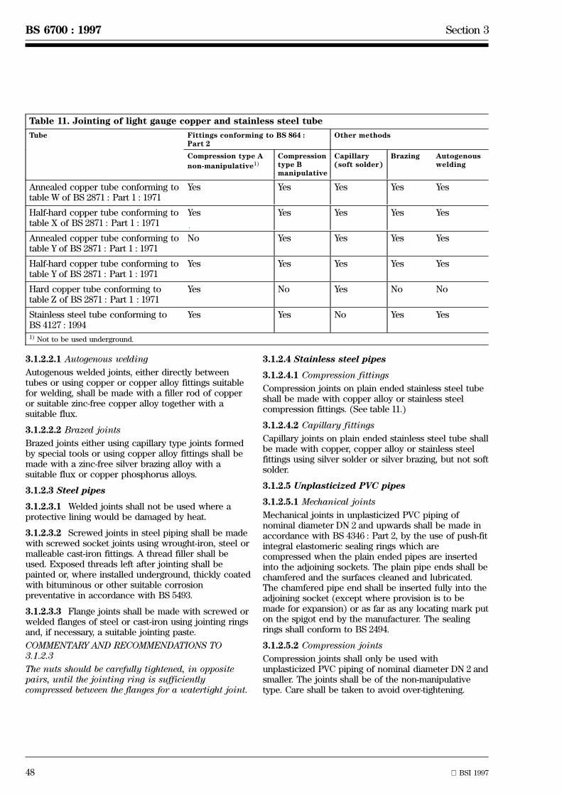
48 BSI 1997
BS 6700 : 1997 Section 3
Table 11. Jointing of light gauge copper and stainless steel tube
Tube Fittings conforming to BS 864 :Part 2
Other methods
Compression type A
non-manipulative1)
Compressiontype Bmanipulative
Capillary(soft solder)
Brazing Autogenouswelding
Annealed copper tube conforming totable W of BS 2871 : Part 1 : 1971
Yes Yes Yes Yes Yes
Half-hard copper tube conforming totable X of BS 2871 : Part 1 : 1971
Yes Yes Yes Yes Yes
Annealed copper tube conforming totable Y of BS 2871 : Part 1 : 1971
No Yes Yes Yes Yes
Half-hard copper tube conforming totable Y of BS 2871 : Part 1 : 1971
Yes Yes Yes Yes Yes
Hard copper tube conforming totable Z of BS 2871 : Part 1 : 1971
Yes No Yes No No
Stainless steel tube conforming toBS 4127 : 1994
Yes Yes No Yes Yes
1) Not to be used underground.
3.1.2.2.1 Autogenous welding
Autogenous welded joints, either directly betweentubes or using copper or copper alloy fittings suitablefor welding, shall be made with a filler rod of copperor suitable zinc-free copper alloy together with asuitable flux.
3.1.2.2.2 Brazed joints
Brazed joints either using capillary type joints formedby special tools or using copper alloy fittings shall bemade with a zinc-free silver brazing alloy with asuitable flux or copper phosphorus alloys.
3.1.2.3 Steel pipes
3.1.2.3.1 Welded joints shall not be used where aprotective lining would be damaged by heat.
3.1.2.3.2 Screwed joints in steel piping shall be madewith screwed socket joints using wrought-iron, steel ormalleable cast-iron fittings. A thread filler shall beused. Exposed threads left after jointing shall bepainted or, where installed underground, thickly coatedwith bituminous or other suitable corrosionpreventative in accordance with BS 5493.
3.1.2.3.3 Flange joints shall be made with screwed orwelded flanges of steel or cast-iron using jointing ringsand, if necessary, a suitable jointing paste.
COMMENTARY AND RECOMMENDATIONS TO3.1.2.3
The nuts should be carefully tightened, in oppositepairs, until the jointing ring is sufficientlycompressed between the flanges for a watertight joint.
3.1.2.4 Stainless steel pipes
3.1.2.4.1 Compression fittings
Compression joints on plain ended stainless steel tubeshall be made with copper alloy or stainless steelcompression fittings. (See table 11.)
3.1.2.4.2 Capillary fittings
Capillary joints on plain ended stainless steel tube shallbe made with copper, copper alloy or stainless steelfittings using silver solder or silver brazing, but not softsolder.
3.1.2.5 Unplasticized PVC pipes
3.1.2.5.1 Mechanical joints
Mechanical joints in unplasticized PVC piping ofnominal diameter DN 2 and upwards shall be made inaccordance with BS 4346 : Part 2, by the use of push-fitintegral elastomeric sealing rings which arecompressed when the plain ended pipes are insertedinto the adjoining sockets. The plain pipe ends shall bechamfered and the surfaces cleaned and lubricated.The chamfered pipe end shall be inserted fully into theadjoining socket (except where provision is to bemade for expansion) or as far as any locating mark puton the spigot end by the manufacturer. The sealingrings shall conform to BS 2494.
3.1.2.5.2 Compression joints
Compression joints shall only be used withunplasticized PVC piping of nominal diameter DN 2 andsmaller. The joints shall be of the non-manipulativetype. Care shall be taken to avoid over-tightening.
Section 3 BS 6700 : 1997
BSI 1997 49
3.1.2.5.3 Solvent cement welded joints
Solvent cement welded joints in unplasticized PVCpiping shall be made using a solvent cementconforming to BS 4346 : Part 3 recommended by themanufacturer of the pipe. The dimensions of thespigots and sockets shall conform to BS 4346 :Part 1 and reference shall be made to CP 312 :Part 2 for jointing methods.NOTE. Joints may also be made using integral sockets formed inthe pipes and solvent cemented.
3.1.2.5.4 Flanged joints
Flanged joints used for connections to valves andfittings shall use full-face flanges or stub-flange, bothwith corrosion resistant or immune backing rings andbolting.
3.1.2.6 Polyethylene pipes
3.1.2.6.1 Mechanical joints shall be made inaccordance with CP 312 using either plastics or metalproprietary compression fittings, e.g. brass, gun metalor malleable iron. These shall include liners to supportthe bore of the pipe except where the manufacturer ofthe fitting instructs otherwise.
3.1.2.6.2 To ensure satisfactory jointing of thematerials from which the pipe and fittings are madecompatibility shall be established. The manufacturer'sinstructions shall be carefully followed.
No attempt shall be made to joint polyethylene pipingby solvent cement welding.
3.1.2.7 Polybutylene pipes
Mechanical joints in polybutylene pipes conforming toBS 7291 : Part 2 shall be made using fittings conformingto the same standard.
3.1.3 Connections between different materials
3.1.3.1 Above ground pipework
When different materials are used within a singleinstallation the method of jointing shall be designed forboth materials, for the safety and integrity of thesystem.
COMMENTARY AND RECOMMENDATIONSON 3.1.3.1
Adaptor couplings are available for this purposecovering a range of different jointing methods andincluding both direct and union type couplings; theseshould be used whenever possible. Where suitableadaptors are not available for the particular jointrequired both materials should be adapted to BS Pthreaded ends which should be screwed together, ifmale and female, or should be connected by a nipple,socket or union.
3.1.3.2 Below-ground pipework
Joints in buried pipework shall be kept to the absoluteminimum and joints between pipes of differentmaterials shall be restricted to connections betweenlarge supply pipes similar to suppliers' mains and pipesserving individual buildings, such as will occur on largesites only.
Service connections to cast iron pipes shall be madeby drilling and tapping the pipe and screwing in acopper alloy union ferrule.
For making service connections to unplasticized PVCpipes, a saddle shall be fixed round the larger pipe anda ferrule screwed into the saddle. Installers shallobserve the manufacturer's instructions. In the case offibre cement pipes the same method shall be used or aproprietary threadless ferrule shall be used inaccordance with the manufacturer's instructions.
Service connections to PE pipes shall be made usingeither a saddle fusion fitting (for PE service pipesonly) or a self-tapping saddle.
3.1.4 Joining pipes to cisterns and tanks
3.1.4.1 General
Cisterns and tanks shall be properly supported toavoid undue stress on the pipe connections anddeformation of the cistern or tank when filled. Holesshall be correctly aligned for the connection of pipesto cisterns and tanks. All debris shall be removed fromthe inside of the cistern or tank before filling.
3.1.4.2 Steel pipes to steel or glass reinforcedcisterns and tanks
The threaded end of the pipe shall be secured in thehole in the cistern or tank either by backnuts andwashers both inside and outside (soft washers beingused additionally with glass reinforced plastics cisternsand tanks or where there are irregular surfaces) or byusing bolted or welded flanged connections.
3.1.4.3 Copper or plastics pipe to steel, or glassreinforced plastics cisterns and tanks
A copper alloy connector having a shoulder to bear onthe outside of the cistern or tank and secured by abacknut to the inside shall be used. Corrosion resistantsupport washers shall be used both on the inside andthe outside of the cistern or tank; additional softwashers shall be used as in 3.1.4.2.
3.1.4.4 Concrete cisterns and tanks
Connections to concrete cisterns and tanks shall bemade with short thread flanged connections having apuddle flange either cast or welded on. Connectionsshall be properly aligned both in the horizontal andvertical planes when being cast into the concrete,which shall be compacted around the puddle flange toensure a watertight joint.
3.1.4.5 Thermoplastics cisterns
Holes cut for pipes shall be circular, have clean edgesand be free from notches. There shall not be anyresidual scribe lines after the hole is cut.
Where a jointing sealant is required it shall conform toBS 6956 : Part 5.
A supporting back plate shall be used on the outside ofthe cistern where the float-operated valve is fitted, tospread the thrust of the lever arm over a greater areaof the side wall. Corrosion resistant support washersshall be used both on the inside and the outside of thecistern with additional soft washers.

50 BSI 1997
BS 6700 : 1997 Section 3
NOTE. Figure 14 is based on a figure taken from the Plumbing engineering services design guide [9], by kindpermission of the Institute of Plumbing.
Figure 14. Directions of thrusts developed in a pipeline due to internal pressure
3.1.5 Underground pipe laying
3.1.5.1 General
Pipes shall be laid to ensure even support throughouttheir length and shall not rest on their sockets or onbricks, tiles or other makeshift supports. Plastics pipesshall be laid in accordance with CP 312 :Parts 1, 2 and 3 on a bed free from sharp stones.
COMMENTARY AND RECOMMENDATIONSON 3.1.5.1
Pipes should be laid true to line to the generalcontours of the ground and at a sufficient depth forthe pipe diameter to allow for the minimum coverbelow finished ground level (see 2.1.8).
3.1.5.2 Trench excavations
The bottom of trench excavations shall be carefullyprepared to a firm even surface so that the barrels ofthe pipes when laid are well bedded for their wholelength. Mud, rock projections, boulders, hard spots andlocal soft spots shall be removed and replaced withselected fill material consolidated to the required level.
Where rock is encountered, the trench shall be cut atleast 150 mm deeper than other ground and made upwith well rammed material.
3.1.5.3 Trench backfilling
When backfilling trenches the pipes shall besurrounded with suitable material consolidated toresist subsequent movement of the pipes.
No large stones or sharp objects shall be in contactwith the pipes.
3.1.5.4 Ingress of dirt
Pipes shall be kept clean and, immediately beforelaying each pipe and fitting, shall be thoroughlycleansed internally and the open end temporarilycapped until jointing takes place. Care shall be takento keep the joint surfaces clean. After laying andjointing, the leading end shall remain capped.
COMMENTARY AND RECOMMENDATIONSON 3.1.5.4
Precautions should be taken to prevent flotation of thecapped pipes, in case the trench becomes flooded.
3.1.5.5 Protective coatings
Coatings, sheathings or wrappings shall be examinedfor damage, repaired where necessary, and madecontinuous before trench excavations are backfilled.
3.1.5.6 Restraint of pipes
Except where the method of joining and normal trenchbackfill are adequate to prevent longitudinalmovement, pipe restraints designed to resist the thrustsproduced by the test pressure to be applied shall beinstalled at all changes of direction and blank ends.The magnitudes of these thrusts, which act in thedirections shown in figure 14, shall be calculated asfollows.
End thrust (in kN) = 100 AP
Radial thrust at bends (in kN) = 100 AP3 2sin u/2
where
A is the cross-sectional area of the inside of socket(in m2);
P is the test pressure (in bar);
u is the angle of deviation of bend.
Alternatively, when standard fittings are used, thethrusts shall be calculated by multiplying the valuesgiven in table 12 by the test pressure (bar).
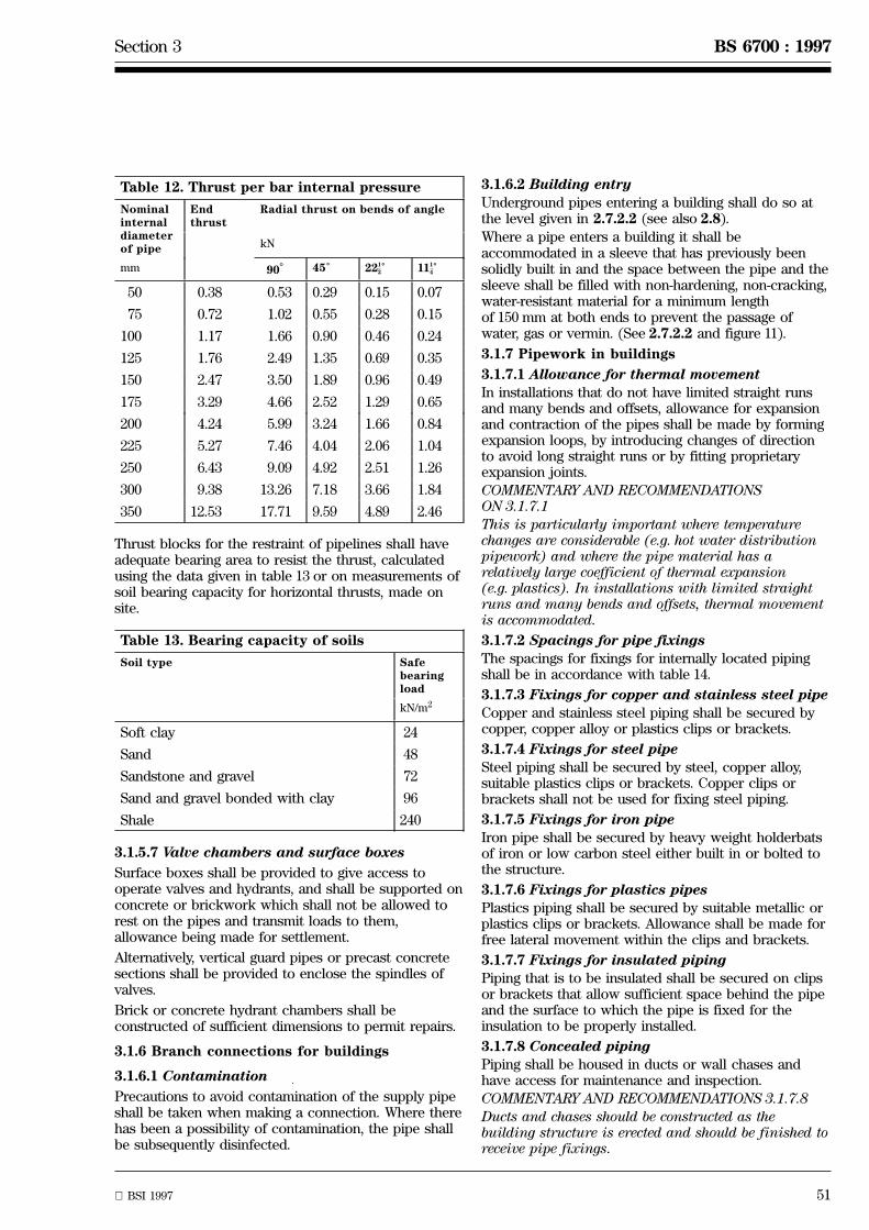
Section 3 BS 6700 : 1997
BSI 1997 51
Table 12. Thrust per bar internal pressure
Nominalinternaldiameterof pipe
Endthrust
Radial thrust on bends of angle
kN
mm 90Ê 45Ê 22 Ê1
2 11 Ê1
4
50 0.38 0.53 0.29 0.15 0.07
75 0.72 1.02 0.55 0.28 0.15
100 1.17 1.66 0.90 0.46 0.24
125 1.76 2.49 1.35 0.69 0.35
150 2.47 3.50 1.89 0.96 0.49
175 3.29 4.66 2.52 1.29 0.65
200 4.24 5.99 3.24 1.66 0.84
225 5.27 7.46 4.04 2.06 1.04
250 6.43 9.09 4.92 2.51 1.26
300 9.38 13.26 7.18 3.66 1.84
350 12.53 17.71 9.59 4.89 2.46
Thrust blocks for the restraint of pipelines shall haveadequate bearing area to resist the thrust, calculatedusing the data given in table 13 or on measurements ofsoil bearing capacity for horizontal thrusts, made onsite.
Table 13. Bearing capacity of soils
Soil type Safebearingload
kN/m2
Soft clay 24
Sand 48
Sandstone and gravel 72
Sand and gravel bonded with clay 96
Shale 240
3.1.5.7 Valve chambers and surface boxes
Surface boxes shall be provided to give access tooperate valves and hydrants, and shall be supported onconcrete or brickwork which shall not be allowed torest on the pipes and transmit loads to them,allowance being made for settlement.
Alternatively, vertical guard pipes or precast concretesections shall be provided to enclose the spindles ofvalves.
Brick or concrete hydrant chambers shall beconstructed of sufficient dimensions to permit repairs.
3.1.6 Branch connections for buildings
3.1.6.1 Contamination
Precautions to avoid contamination of the supply pipeshall be taken when making a connection. Where therehas been a possibility of contamination, the pipe shallbe subsequently disinfected.
3.1.6.2 Building entry
Underground pipes entering a building shall do so atthe level given in 2.7.2.2 (see also 2.8).
Where a pipe enters a building it shall beaccommodated in a sleeve that has previously beensolidly built in and the space between the pipe and thesleeve shall be filled with non-hardening, non-cracking,water-resistant material for a minimum lengthof 150 mm at both ends to prevent the passage ofwater, gas or vermin. (See 2.7.2.2 and figure 11).
3.1.7 Pipework in buildings
3.1.7.1 Allowance for thermal movement
In installations that do not have limited straight runsand many bends and offsets, allowance for expansionand contraction of the pipes shall be made by formingexpansion loops, by introducing changes of directionto avoid long straight runs or by fitting proprietaryexpansion joints.
COMMENTARY AND RECOMMENDATIONSON 3.1.7.1This is particularly important where temperaturechanges are considerable (e.g. hot water distributionpipework) and where the pipe material has arelatively large coefficient of thermal expansion(e.g. plastics). In installations with limited straightruns and many bends and offsets, thermal movementis accommodated.
3.1.7.2 Spacings for pipe fixings
The spacings for fixings for internally located pipingshall be in accordance with table 14.
3.1.7.3 Fixings for copper and stainless steel pipe
Copper and stainless steel piping shall be secured bycopper, copper alloy or plastics clips or brackets.
3.1.7.4 Fixings for steel pipe
Steel piping shall be secured by steel, copper alloy,suitable plastics clips or brackets. Copper clips orbrackets shall not be used for fixing steel piping.
3.1.7.5 Fixings for iron pipe
Iron pipe shall be secured by heavy weight holderbatsof iron or low carbon steel either built in or bolted tothe structure.
3.1.7.6 Fixings for plastics pipes
Plastics piping shall be secured by suitable metallic orplastics clips or brackets. Allowance shall be made forfree lateral movement within the clips and brackets.
3.1.7.7 Fixings for insulated piping
Piping that is to be insulated shall be secured on clipsor brackets that allow sufficient space behind the pipeand the surface to which the pipe is fixed for theinsulation to be properly installed.
3.1.7.8 Concealed piping
Piping shall be housed in ducts or wall chases andhave access for maintenance and inspection.
COMMENTARY AND RECOMMENDATIONS 3.1.7.8Ducts and chases should be constructed as thebuilding structure is erected and should be finished toreceive pipe fixings.
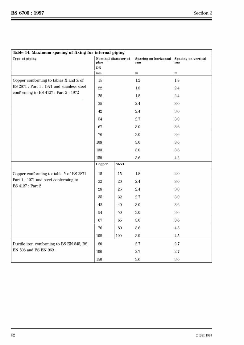
52 BSI 1997
BS 6700 : 1997 Section 3
Table 14. Maximum spacing of fixing for internal piping
Type of piping Nominal diameter ofpipe
Spacing on horizontalrun
Spacing on verticalrun
DN
mm m m
Copper conforming to tables X and Z of
BS 2871 : Part 1 : 1971 and stainless steel
conforming to BS 4127 : Part 2 : 1972
15 1.2 1.8
22 1.8 2.4
28 1.8 2.4
35 2.4 3.0
42 2.4 3.0
54 2.7 3.0
67 3.0 3.6
76 3.0 3.6
108 3.0 3.6
133 3.0 3.6
159 3.6 4.2
Copper Steel
Copper conforming to: table Y of BS 2871
Part 1 : 1971 and steel conforming to
BS 4127 : Part 2
15 15 1.8 2.0
22 20 2.4 3.0
28 25 2.4 3.0
35 32 2.7 3.0
42 40 3.0 3.6
54 50 3.0 3.6
67 65 3.0 3.6
76 80 3.6 4.5
108 100 3.9 4.5
Ductile iron conforming to BS EN 545, BS
EN 598 and BS EN 969.
80 2.7 2.7
100 2.7 2.7
150 3.6 3.6

Section 3 BS 6700 : 1997
BSI 1997 53
Table 14. Maximum spacing of fixing for internal piping (continued)
Type of piping Nominal diameter ofpipe
Spacing on horizontalrun
Spacing on verticalrun
DN
mm m m
Unplasticized polyvinyl chloride (PVC-U)1)
conforming to BS 3505
1
40.6 1.1
1
20.7 1.3
3
40.7 1.4
1 0.8 1.6
11
40.9 1.7
11
21.0 1.9
2 1.1 2.2
3 1.4 2.8
4 1.6 3.1
6 1.9 3.7
Black MDPE pipe conforming to BS 6730 20 0.5 0.9
25 0.6 1.2
32 0.6 1.2
50 0.8 1.5
63 0.8 1.6
Chlorinated polyvinyl chloride (PVC-C)2)
conforming to BS 7291 : Parts 1 and 4
12 to 25 0.5 1.0
32 to 63 0.8 2.2
Polybutylene (PB) and cross-linked
polyethylene (PE-X)2) conforming to
BS 7291 : Parts 2 and 3
Up to 16 0.3 0.5
18 to 25 0.5 0.8
28 0.8 1.0
32 0.9 1.2
35 0.9 1.21) Figures are for normal ambient temperatures below 20 ÊC. For temperatures above 20 ÊC the pipe manufacturer should beconsulted.
2) Based on water temperature up to 80 ÊC.

54 BSI 1997
BS 6700 : 1997 Section 3
������
������
X
0.25 L
0.07 L
0.4 L
Y 0.25 L
Span L
3d min.
d
Dep
th (
D)
Spacing of holes
D8/
max
.
D2/
NOTE.
X is the allowable limits of location for cut notches, to be in either the top or bottom surface,not both.
Y is the allowable location for drilled holes.
d is the diameter of the larger of two adjacent holes.
The diameter (d) shall not exceed .D
4
Figure 15. Recommended positions of notches and holes in timberbeams and joists
3.1.7.9 Piping passing through structural timbersStrutural timbers shall not be notched or bored in sucha way that the integrity of the structure iscompromised.
COMMENTARY AND RECOMMENDATIONS ON3.1.7.9Structural timbers should only be notched or boredwith the permission of, and as directed by, thearchitect, structural engineer and/or supervisingofficer for the building. Notches and holes should be assmall as necessary to receive pipes. Whenever possible,notches should be U shaped and formed by parallelcuts to previously bored holes.
It is essential that structural members are notweakened by indiscriminate notching and boring. Inthis respect the positions are as important as thesizes of notches and holes. Notches and holes intimber beams and joists should only be madeaccording to dimensions shown in figure 15.
3.1.7.10 Clearance of structural membersPiping laid through notches, holes, cut-outs or chasesshall not be subjected to external forces and shall befree to expand or contract. Pipe sleeves shall beprovided where piping passes through walls and floors.
3.1.7.11 Penetration of fire walls and floors
Penetration of compartment walls and floors and firebarriers shall be fire-stopped to prevent the passage ofsmoke and flame, (see A.1).
3.1.8 Electrical bonding
No water pipe shall be used as an electrode forearthing purposes, but all metal pipes shall be bondedto the electrical installation main earth terminal as nearas possible to the point of entry into the building(see 2.2.8.3 and 4.2.5.)
3.1.9 Taps
Taps not fixed directly to an appliance shall bescrewed into a suitable pipe fitting and the fitting, orthe pipe immediately adjacent to the tap, shall befirmly secured to a suitable support, so as to preventstrain on the pipe and its joints when the tap isoperated.
COMMENTARY AND RECOMMENDATIONS ON 3.1.9
The use of a backplate elbow to receive the tap and awall flange plugged and screwed to the wall or supportis preferred.
Section 3 BS 6700 : 1997
BSI 1997 55
3.1.10 Flushing and disinfection
3.1.10.1 Flushing
Every new water service, cistern, distributing pipe, hotwater cylinder or other appliance and any extension ormodification to such a service shall be thoroughlyflushed with drinking water before being taken intouse. Where a system is not brought into useimmediately after commissioning and it has not beenflushed at regular intervals (up to 30 days depending onthe characteristics of the water), it shall be disinfectedbefore bringing into use.
3.1.10.2 Disinfection
After flushing, systems shall be disinfected inaccordance with 3.1.10.3 to 3.1.10.5 in the followingsituations:
a) in new installations (except private dwellingsoccupied by a single family);
b) where major extensions or alterations have beencarried out;
c) where underground pipework has been installed(except where localized repairs only have beencarried out or junctions have been inserted(see 3.1.10.6);
d) where it is suspected that contamination mayhave occurred, e.g. fouling by sewage, drainage,animals or physical entry by site personnel forinterior inspection, painting or repairs;
e) where a system has not been in regular use andnot regularly flushed.
Where any pipework under mains pressure orupstream of any back-flow prevention device withinthe installation is to be disinfected, the water suppliershall be informed.
Chemicals used for disinfection of drinking waterinstallations shall be those that are listed in theDrinking Water Inspectorate's List of substances,products and processes approved underregulations 25 and 26 for use in connection with thesupply of water for drinking, washing, cooking orfood production purposes, Sections 4 and 5, which ispublished in part 4 of the Water fittings and materialsdirectory [1].
Where water that has been used to disinfect aninstallation is to be discharged into a sewer, theauthority responsible for that sewer shall be informedprior to discharge.
Where this water is to be discharged into a watercourse or into a drain leading to the same, a consentto discharge shall be obtained from the appropriateauthority; that is, the National Rivers Authority (NRA)in England and Wales, the Scottish EnvironmentalProtection Agency in Scotland and the Department ofthe Environment for Northern Ireland in NorthernIreland.
The sequence of disinfection shall be water mains,service pipes cisterns and the internal distributionsystem.
COMMENTARY AND RECOMMENDATIONSON 3.1.10.2
Flushing and disinfection are not a substitute for ahigh degree of cleanliness during installation.(See also 3.1.5.4.)
For single dwellings and minor extensions oralterations in any premises, flushing is all that isnormally required, unless contamination is suspected.
3.1.10.3 Safety
Systems, or parts of systems, shall not be used duringthe disinfection procedure and all outlets shall bemarked with `DISINFECTION IN PROGRESS, DO NOTUSE'.
To avoid the generation of toxic fumes, no otherchemicals, like toilet cleansers shall be added to thewater until disinfection is complete.
All building users shall be informed of the disinfectionbefore it takes place. This includes those users notnormally in attendance during working hours,i.e. cleaners and security guards.
3.1.10.4 Disinfection procedure
The system to be disinfected shall be thoroughlyflushed prior to commencement of the disinfectionprocedure.
3.1.10.4.1 Methods using chlorine as a disinfectant
The system shall be filled with chlorinated water at aninitial concentration of 50 mg/l (50 p.p.m) for a contactperiod of 1 h. If the free residual chlorine measured atthe end of the contact period is less than 30 mg/l(30 p.p.m) the disinfection process shall be repeated.
After successful chlorination, the system shall beimmediately drained and thoroughly flushed with cleanwater. Flushing shall continue until the free residualchlorine is at the level present in the drinking watersupplied.
3.1.10.4.2 Methods using approved disinfectants otherthan chlorine
The system shall be filled with the approveddisinfectant solution at the initial concentration and forthe contact time specified by the manufacturer. If theresidual of the approved disinfectant at the end of thecontact time is less than the manufacturer'srecommendation, the disinfection procedure shall berepeated.
After successful disinfection, the system shall beimmediately drained and thoroughly flushed with cleanwater. Flushing shall continue in accordance with thedisinfectant manufacturer'sinstructions/recommendations or until there is noevidence of the disinfectant chemical being present, orit is at a level that is no higher than that present in thedrinking water supplied.
56 BSI 1997
BS 6700 : 1997 Section 3
3.1.10.4.3 Post disinfection
After flushing, a sample(s) for bacteriological analysisshall be taken, and analysed, under the supervision ofa microbiologist, who shall also determine the numberand method of collection of samples.
Where a bacteriological analysis of the samplesindicates that adequate disinfection has not beenachieved, the installation shall be flushed,re-disinfected and further samples taken.
COMMENTARY AND RECOMMENDATIONSON 3.1.10.4
Provided there is no suspicion that the system hasbeen fouled by sewage, drainage or animals prior todisinfection, the installation may be put into servicebefore the result of the bacteriological analysis isknown.
For supply pipes (including unvented hot watersystems off the supply pipe) and after flushing,disinfectant solution should be injected through aproperly installed injection point at the upstream endof the supply pipe, until the disinfectant solutiondischarged at the downstream end of the pipeline isequal to the initial concentration; the contact periodthen commences.
In gravity distribution systems within buildings, onemethod of introducing disinfectant solution is asfollows:
After flushing, the system should be filled with waterand the servicing valve on the supply to the cisternclosed. The capacity of the cistern should be assessedand a calculated quantity of disinfectant solution ofknown strength should be added to the cistern to givethe initial concentration of disinfectant solution inthe cistern. The disinfectant solution should be drawnaround the system by successively opening eachdraw-off fitting, working away from the cistern, andclosing it when disinfectant solution at the initialconcentration is discharged, (as determined by usingcolorimetric methods, where possible). The cisternshould be refilled and disinfected as above asnecessary during this operation, maintaining theinitial concentration of disinfectant solution in thecistern at all times. The contact time shouldcommence when the entire system is filled withdisinfectant solution, including the cistern, up tooverflow level.
Irrespective of the method of disinfection, the contacttime commences when the entire system, includingthe cistern up to overflow level, is full of disinfectantsolution at the required initial concentration.
3.1.10.5 Cisterns with internal coatings
Because high chlorine concentrations and otherdisinfectants can adversely affect new coatings incisterns and release chlorinated or other compoundsinto the water the coating shall be thoroughly curedbefore disinfection takes place and care shall be takennot to exceed 50 mg/l chlorine concentration or, in thecase of an alternative approved disinfectant, themanufacturer's recommendation.
3.1.10.6 Localized repairs
Junctions, or fittings for a localized repair, inserted intoan existing external pipeline shall be disinfected byimmersion in a solution of sodium hypochloritecontaining 200 mg/l of available chlorine. Where otherdisinfectants are used the concentration shall be inaccordance with the manufacturer's recommendations.
3.1.11 Identifying and recording piping locations
3.1.11.1 Location of pipes and valves
Location and position of underground pipes and valvesshall be recorded.
Surface boxes shall be marked to indicate what serviceis below them. Durable markers with stamped or set-inindexes shall be set up to indicate the pipe service, thesize, the position and depth below the surface.Indicator plates for hydrants shall conform to BS 3251.
COMMENTARY AND RECOMMENDATIONSON 3.1.11.1
Marker tapes are available for use and are generallylaid a short distance above the pipe in the trench.
3.1.11.2 Identification of above ground piping
In any building other than a single dwelling:
a) water piping shall be colour banded and coded inaccordance with BS 1710;
b) every supply pipe and every pipe for supplyingwater solely for fire fighting purposes shall beclearly and indelibly marked to distinguish themfrom each other and from every other pipe in thebuilding.
3.1.11.3 Record drawings
During the installation of a water supply system,records of all pipe runs, cisterns, valves and outlets,shall be kept. On completion of the works, recorddrawings of the completed installation shall beprepared. These shall be handed to the owner of thebuilding.
3.1.11.4 Identification of valves and cisternsinstalled above ground
All valves in hot and cold water services pipework andcisterns installed above ground shall be provided withan identification label, either secured bynon-corrodible, incombustible means to the valve orfixed to a permanent structure near the valve. Labelssecured to valves shall be of non-corrodible andincombustible material permanently and clearlymarked, e.g. by stamping or engraving, with adescription of the service concerned and the functionof the valve. Alternatively, the label shall be markedwith a reference number for the valve, instead of or inaddition to the marking described in this subclause,and a durable diagram of the service, showing thevalve reference numbers shall be fixed in a readilyvisible position to a permanent part of the building orstructure. Labels fixed near valves shall conform to therequirements for labels secured to valves except thatthey need not be incombustible.
Section 3 BS 6700 : 1997
BSI 1997 57
COMMENTARY AND RECOMMENDATIONSON 3.1.11.4
In order that the identify and function of each valvein a system can be readily assessed, it isrecommended that a diagrammatic drawing isprovided for every installation.
3.1.12 Inspection testing and commissioning ofinstallations
3.1.12.1 Procedure
3.1.12.1.1 General
Inspections and tests shall be undertaken asinstallation proceeds, and on completion.
Prior notice shall be given to the water supplier beforeany statutory inspections or tests are undertaken.
Records of all tests undertaken shall be kept by theinstaller and handed over to the client on completion.
3.1.12.1.2 Timing of tests
The timing of tests shall be as follows:
a) interim tests: as soon as practicable aftercompletion of the particular section, with particularattention to all work which will be concealed;
b) final tests: to be carried out on completion of allwork on the water system and prior to handing over.
COMMENTARY AND RECOMMENDATIONSON 3.1.12.1.2
Satisfactory completion of an interim test does notconstitute a final test.
3.1.12.1.3 Re-tests
Items failing any test shall be corrected immediatelyand re-tested before further work proceeds.
3.1.12.2 Inspection
Visual inspections by the water supplier shall becarried out at both interim and final testing beforework is concealed, in order to detect faults inconstruction or materials.
All internal pipework shall be inspected to ensure thatit has been securely fixed.
All cisterns, tanks, hot water cylinders and waterheaters shall be inspected to ensure that they areproperly supported and secured, that they are cleanand free from swarf and that cisterns are providedwith correctly fitting covers before testing takes place.
Unvented hot water storage installations shall benotified to the local authority to verify that theyconform to building regulations (see A.1).
Before accepting a pipeline, a check shall be made thatvalve and hydrant boxes are aligned, that operatingkeys are provided for the valves and, in the case ofdeep valves, that extension spindles are installed.
COMMENTARY AND RECOMMENDATIONSON 3.1.12.2
In the case of visual inspection of undergroundpipework, particular attention should be paid to thepipe bed, the line and level of the pipe, irregularitiesat joints, the correct fitting of air valves, washoutvalves, sluice valves and other valves together withany other mains equipment specified, including thecorrect installation of thrust blocks where required, toensure that protective coatings are undamaged.
Trenches should be inspected to ensure that excavationis to the correct depth to guard against frost andmechanical damage due to traffic, ploughing oragricultural activities.
No part of the pipe trench should be backfilled untilthese conditions have been satisfied and theinstallation seen to conform to the drawings andspecifications and the appropriate byelaws andregulations.
3.1.12.3 Hydraulic testing
Defects revealed by any of the following tests shall beremedied and the tests repeated until a satisfactoryresult is obtained.
If the water is obtained from the water supplier'smains it shall be taken in accordance with thesupplier's requirements.
3.1.12.3.1 Testing of underground pipelines
The installation to be tested shall be inspected forcompliance with the drawings and specifications.Significant variations shall be investigated andcorrected, if required, before proceeding with the test.
After laying, jointing and anchoring, the undergroundpipeline shall be slowly and carefully filled with waterso that all air is expelled and then tested underpressure in accordance with clauses 3.1.12.3.3 or3.1.12.3.4, depending on the material from which thepipeline is constructed. The system shall be subjectedto twice the maximum working pressure of thepipeline.
When water from the water supplier's mains is usedfor filling the pipeline under test, the main shall bedisconnected from the pipeline before the test isbegun. To avoid the risk of contamination, water usedfor testing shall be obtained from a drinking supply.
COMMENTARY AND RECOMMENDATIONSON 3.1.12.3.1
Long pipelines should be tested in sections as thework proceeds.
Final tests should be carried out only when allrelevant work is complete. Completion for buriedpipelines includes backfilling, compaction and surfacefinish.
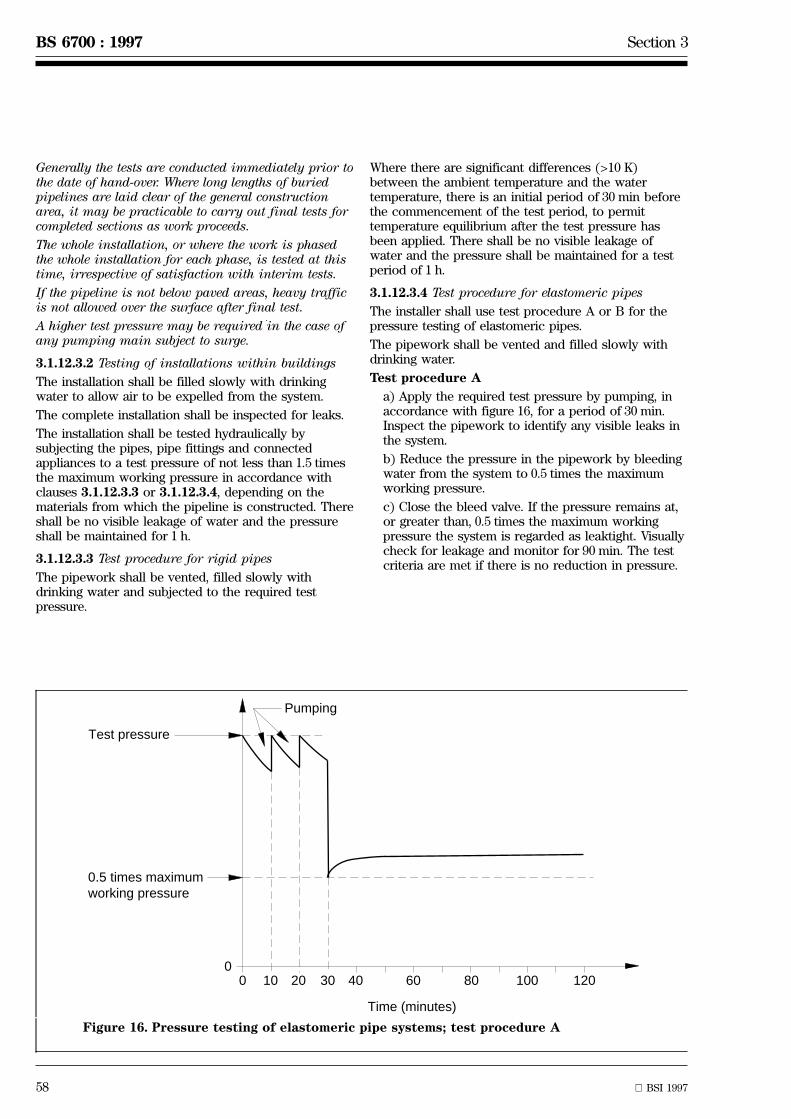
58 BSI 1997
BS 6700 : 1997 Section 3
00
10 20 30 40 60 80 100 120
Time (minutes)
Test pressure
Pumping
0.5 times maximumworking pressure
Figure 16. Pressure testing of elastomeric pipe systems; test procedure A
Generally the tests are conducted immediately prior tothe date of hand-over. Where long lengths of buriedpipelines are laid clear of the general constructionarea, it may be practicable to carry out final tests forcompleted sections as work proceeds.
The whole installation, or where the work is phasedthe whole installation for each phase, is tested at thistime, irrespective of satisfaction with interim tests.
If the pipeline is not below paved areas, heavy trafficis not allowed over the surface after final test.
A higher test pressure may be required in the case ofany pumping main subject to surge.
3.1.12.3.2 Testing of installations within buildings
The installation shall be filled slowly with drinkingwater to allow air to be expelled from the system.
The complete installation shall be inspected for leaks.
The installation shall be tested hydraulically bysubjecting the pipes, pipe fittings and connectedappliances to a test pressure of not less than 1.5 timesthe maximum working pressure in accordance withclauses 3.1.12.3.3 or 3.1.12.3.4, depending on thematerials from which the pipeline is constructed. Thereshall be no visible leakage of water and the pressureshall be maintained for 1 h.
3.1.12.3.3 Test procedure for rigid pipes
The pipework shall be vented, filled slowly withdrinking water and subjected to the required testpressure.
Where there are significant differences (>10 K)between the ambient temperature and the watertemperature, there is an initial period of 30 min beforethe commencement of the test period, to permittemperature equilibrium after the test pressure hasbeen applied. There shall be no visible leakage ofwater and the pressure shall be maintained for a testperiod of 1 h.
3.1.12.3.4 Test procedure for elastomeric pipes
The installer shall use test procedure A or B for thepressure testing of elastomeric pipes.
The pipework shall be vented and filled slowly withdrinking water.
Test procedure A
a) Apply the required test pressure by pumping, inaccordance with figure 16, for a period of 30 min.Inspect the pipework to identify any visible leaks inthe system.
b) Reduce the pressure in the pipework by bleedingwater from the system to 0.5 times the maximumworking pressure.
c) Close the bleed valve. If the pressure remains at,or greater than, 0.5 times the maximum workingpressure the system is regarded as leaktight. Visuallycheck for leakage and monitor for 90 min. The testcriteria are met if there is no reduction in pressure.

Section 3 BS 6700 : 1997
BSI 1997 59
00
10 3020 60 120 180
Time (minutes)
Test pressure
Pumping
Pre
ssur
e dr
op
20 k
Pa
(0.2
bar
)
Pre
ssur
e dr
op
60 k
Pa
(0.6
bar
)
min.
^
^
Figure 17. Testing of elastomeric pipe systems; test procedure B
Test procedure B
a) Apply the required test pressure by pumping, inaccordance with figure 17, for a period of 30 min andnote the pressure in the pipeline at the end of theperiod. Inspect the pipework to identify any visibleleaks in the system. Continue the test withoutfurther pumping.
b) Note the pressure after a further 30 min. If thepressure drop is less than 60 kPa (0.6 bar), thesystem can be considered to have no obviousleakage.
c) Visually check for leakage and monitorfor 120 min. The test criteria are met if the pressuredrop in the system is less than 20 kPa (0.2 bar).
COMMENTARY AND RECOMMENDATIONSON 3.1.12.3.4
Test procedures A and B may also be used where theinstallation comprises both elastomeric and rigidpipes. When not stated otherwise the installer maychoose either test procedure A or B.
3.1.12.4 Connection to water supply system
When all inspections and tests have been successfullycompleted and the system accepted from the installer,the water supplier shall be informed that the system isavailable for permanent connection to the supply.
COMMENTARY AND RECOMMENDATIONSON 3.1.12.5
Each draw-off tap, shower fitting and float-operatedvalve should be checked for rate of flow against thespecified requirements. Performance tests should alsobe carried out on any connected specialist items toshow that they meet the requirements detailed in thespecification.
60 BSI 1997
BS 6700 : 1997
Section 4. Maintenance
4.1 Maintenance proceduresMaintenance procedures shall be adopted to maintainthe performance of the installation at the levelspecified in this standard for the original design andinstallation.
Unvented hot water storage installations shall bemaintained and repaired only by a competent person(see building regulations A.1).
COMMENTARY AND RECOMMENDATIONS ON 4.1The degree of formalization of maintenance requireddepends upon the size and utilization of theinstallation although the principles involved apply toall installations.
Maintenance of ducts would not normally apply tosingle dwellings but other requirements should besatisfied by the owner of the building.
In single dwellings the responsibility for maintenancenormally rests on the householders who should payattention to apparent leakages and should note anydischarges from overflow pipes or regular dischargesfrom any valves.
The owner of the building should have been providedwith maintenance instructions and an accuratedrawing of the installation, particularly showingwhere pipe runs are concealed. Control valves shouldbe clearly labelled (see 3.1.11.4). Care should be takento renew or protect labels when redecorating. Anyalterations should be recorded on inspection, and acheck made that these do not introduce undesirablefeatures or contravene statutory requirements.
The services of a competent person should be obtainedto carry out maintenance and repairs. Competenceincludes the appropriate skills and a knowledge of therelevant statutory requirements relating to watersupply.
4.2 General4.2.1 Inspection
In other than single dwellings, the installation shall beinspected periodically. Faults noticed on inspectionshall be attended to immediately.
COMMENTARY AND RECOMMEDATIONS ON 4.2.1The need for formalized inspection and recordsdepends upon the size, type and complexity of theinstallation but in principle every installation shouldbe inspected at least once per year in addition to anystatutory inspections. Checks should be made that theappropriate back-siphonage prevention devices andrelief valves are fitted where required.
4.2.2 Preventative maintenanceManufacturer's recommendations or instructionsregarding planned preventative maintenance of meters,pumps, treatment plant and similar equipment shall befollowed.
4.2.3 Waste prevention
Attention shall be paid to rectify any instances ofwaste or undue consumption of water revealed byinspections or during maintenance operations.
COMMETARY AND RECOMMENDATIONS ON 4.2.3
In the case of metered installations the water meterprovides an easy means of monitoring consumption.The meter or meters should be read at regularintervals and appropriate action taken if anunexplained increase in consumption is indicated.
4.2.4 Water analysis
In other than single dwellings regular analyses of watersamples at intervals not exceeding 6 months shall becarried out wherever drinking water is stored.
COMMENTARY AND RECOMMENDATIONS ON 4.2.4
Periodic chemical and bacteriological analysis ofwater samples is a useful guide to the condition of aninstallation. The collection and analysis of watersamples is particularly recommended for newinstallations in large buildings or complexes andwhere extensive repairs or alterations have beencarried out to such installations.
4.2.5 Earthing and bonding
Where pipework, fittings or appliances are to bereplaced, continuity of earthing and equipotentialbonding shall be maintained (see 2.2.8.3 and 3.1.8).Where pipework has been used for earthing, alternativeearthing arrangements shall be made in consultationwith the electricity supplier and in accordance withBS 7430.
4.2.6 Water temperatures
In other than single dwellings checks shall be made onthe temperature of water in pipes, cold water cisterns,hot water storage vessels and the discharge from tapsto ensure that they are within the limits as listed in2.6.4.
COMMENTARY AND RECOMMENDATIONS ON 4.2.6
These checks should be carried out during the mostadverse conditions, such as at the end of a weekend,during hot weather, full central heating load in thecase of cold weather and during high draw-off in coldconditions.
Should checks reveal unacceptable temperatures, itwill be necessary to install additional insulation,trace heating or carry out modifications or repairs tothe systems.
4.2.7 Cleaning and disinfection
Where there is a risk of legionella colonization ofwater services the system shall be cleaned anddisinfected:
a) if the system, or part of it, has been substantiallyaltered or opened for maintenance purposes in amanner which may lead to contamination;
b) following an outbreak or suspected outbreak oflegionellosis.
COMMENTS AND RECOMMENDATIONS ON 4.2.7
Disinfection of the water system may be undertaken;
a) for both the cold and hot water system, asdescribed in 3.1.10; andb) for the hot water system only, by thermaldisinfection procedures.(See HS(G)70 [3].)
Section 4 BS 6700 : 1997
BSI 1997 61
4.3 Pipework
4.3.1 Fixings and supports
Provision for expansion and contraction shall bechecked. Any loose or missing fixings or supports shallbe replaced.
4.3.2 Joints
Leaking joints shall be rectified or where necessary thepipework shall be renewed, to stop all leakage.
4.3.3 Compatibility
When carrying out renewals, the existing pipeworkshall be identified and appropriate adaptors used,particularly where the original pipework is an imperialsize.
COMMENTARY AND RECOMMENDATIONS ON 4.3.3
Pipes, fittings, components and materials of onemanufacturer are not always compatible with those ofanother manufacturer, even when they conform to thesame British Standard. This applies particularly towelding of plastics pipes, sockets for patentelastomeric ring joints and the threads oncompression fittings.
4.3.4 Corrosion
If inspection of the system reveals leaks or leaks whichhave stifled, that component of the system shall bereplaced and the offending parts examined by anexpert to determine the cause of the leakage. Furtheraction shall be dependent on the results of theexamination and recommendations of the examiningexpert.
COMMENTARY AND RECOMMENDATIONS ON 4.3.4
Pipes showing signs of serious external corrosionshould be replaced. The replacement pipe should havesuitable protection (e.g. factory plastics coated,spirally wrapped or sleeved with an imperviousmaterial) or should be of a corrosion resistantmaterial compatible with the remaining pipework.
4.3.5 Thermal insulation and fire stopping
Any damage to thermal insulation or fire stoppingrevealed during inspection shall be rectified.
COMMENTARY AND RECOMMENDATIONS ON 4.3.5
The integrity of thermal insulation used for frostprotection should be checked at the beginning ofwinter.
4.4 Terminal fittings, valves and metersLeakage from a float-operated valve (e.g. dripping froma warning pipe) or tap shall be rectified to stop theleakage. Self-closing taps shall be checked at regularintervals to ensure that the period of closing is notexcessive.
COMMENTARY AND RECOMMENDATIONS ON 4.4
In addition to preventing leakage, the free movementof infrequently used float-operated valves, particularlythose fitted to the feed and expansion cisterns of hotwater or space heating systems should be checked atintervals not exceeding one year.
Spray heads on taps and showers should be cleanedperiodically and descaled.
Gland packings on taps should be tightened orrenewed as necessary to prevent any leakage while notimpeding the normal operation of the fitting.
Stopvalves should be operated at least once per year toensure free movement of working parts.
Any stiffness or leakage through the gland should bedealt with by lubrication, adjustment or replacementof gland packings or seals. If there is any indicationof leakage past the seating the valve should berewashered, reseated or replaced as necessary. If thereis any indication that the waterway is blocked, thevalve should be dismantled, cleared and restored togood working order or replaced.
Operation of easing gear may cause the valve to leak.
Meters (other than the water supplier's meters) shouldbe removed at such intervals as experience showsnecessary for cleaning and renewal of worn parts,and recalibration.
Any indication of malfunction of a pressure controlvalve should be investigated and remedied.
Discharge from an expansion valve or from a cisternwarning pipe indicates a possible malfunction of apressure reducing valve, pressure limiting valve orexpansion vessel.
Where a pressure gauge is fitted downstream of apressure control valve, its reading should be checkedfrom time to time and any changes investigated.
62 BSI 1997
BS 6700 : 1997 Section 4
4.5 CisternsCisterns shall be inspected to ensure that overflow andwarning pipes are clear, that covers are adequate andsecurely fixed, and that there are no signs of leakageor deterioration likely to result in leakage. Cisternsstoring drinking water shall be inspected annually ormore frequently if contamination is suspected.
COMMENTARY AND RECOMMENDATIONS ON 4.5
Cisterns are weak points in the prevention ofcontamination of water distribution systems andtherefore require particular attention. Overflow andwarning pipes should be checked from time to time toensure that they conform to 2.2.4. All debris should beremoved from cisterns and should be emptied, cleanedand disinfected. Where drinking water has been storedin an inadequately protected cistern, a water analysisshould be considered (see 4.2.4) and adequateprotection installed (see 2.2.3.1.1).
Metal cisterns showing signs of leakage or corrosionshould preferably be replaced but they can be repairedby internal coating or lining, in accordance with themanufacturer's instructions, with a materialconforming to BS 6920 as suitable for use in contactwith drinking water.
In cistern installations, a check should be made forstagnant water. If stagnant water is found, thecistern(s) should be flushed and the flowconfiguration modified so that the flow displaces thewhole of the contents continually when the cistern isin routine use.
4.6 DuctsDucts shall be kept accessible, clear of debris and freefrom vermin.
COMMENTARY AND RECOMMENDATIONS ON 4.6
All access points should be checked to ensure that theyhave not been obstructed. Regular inspections shouldbe made to detect any vermin and any necessarymeasures taken for disinfestation.
Crawlways and subways should be inspected atintervals not exceeding 6 months. They should bechecked for leakage from pipework, ingress of groundor surface water and accumulation of flammablematerials.
4.7 Vessels under pressureAny vessels storing water under pressure shall beinspected for indications of deterioration no lessfrequently than at the intervals recommended by themanufacturer.
Expansion vessels shall be inspected for indications ofdeterioration in strength and the gas pressuremeasured no less frequently than at the intervalsrecommended by the manufacturer. If the gas pressureis not within the limits specified for the application itshall be adjusted to within those limits.
4.8 Disconnection of unused pipes andfittingsIf any part of an installation becomes redundant, andin particular if any appliance or fitting is disconnected,other than for the purpose of repair, maintenance orrenewal, then the whole of the pipework supplyingwater to the disconnected or unused appliance orfitting shall also be disconnected at the source.
COMMENTARY AND RECOMMENDATIONS ON 4.8
It is undesirable and may be dangerous to havelengths of pipework containing motionless or stagnantwater connected to the service installation. The waterbyelaws prescribe a maximum period of 60 daysduring which water fittings may be disconnected forrepair or renewal without disconnecting the pipeworksupplying them with water.
BS 6700 : 1997
BSI 1997 63
Annexes
Annex A (informative)
Legal issues
A.1 Building regulations
A.1.1 England and Wales
The Building Regulations made by the Secretary ofState for the Environment under the BuildingAct 1984 cover the health and safety of persons in andabout buildings. Requirements are not included for thedirect supply of public utilities, such as water, gas orelectricity although (six) specified items are related towater installations.
The requirements for these items are made underregulations 4, 5 and 6 and listed in schedule 1 of theregulations to cover:
± provision of wash basins in conjunction with waterclosets and a suitable installation for the provision ofhot and cold water to wash basins and provision foreffective cleaning of water closets and urinals (G1);
± provision of a bath or shower bath and a suitableinstallation for the provision of hot and cold waterto the bath or shower bath (G2);
± provision of sufficient precautions againstexplosion in unvented hot water systems (G3);
± requirements for controls on certain space andwater heating installations and insulation of hotwater heating and supply pipes, warm air ducts andhot water storage vessels (L1).
The requirements apply to the construction orinstallations work and there is no on-going requirementfor maintenance or inspection. They are written in afunctional form. The regulations are a statutoryinstrument; guidance on ways of meeting therequirements is given in approved documents.
Control of building work under the regulations is amatter for local authorities or approved inspectors.Local authorities also have powers under othersanitation and building legislation such as the PublicHealth Acts. Local authorities and approved inspectorsalso have powers to inspect work during construction.Disputes regarding a local authority's application of theregulations may have to be decided ultimately in acourt of law; it is not always appreciated thatcontravening building regulations is a criminal offence.
Building work generally involves more than onestatutory instrument and any person undertaking waterinstallations or other works should be aware of therelevant requirements in such statutory or guidancedocuments as building regulations, water byelaws, gasregulations and electrical wiring regulations.
A.1.2 Scotland
In Scotland the Building Standards (Scotland)Regulations, made under the Building (Scotland)Act 1959, apply in respect of:
± drainage and sanitary facilities (M);
± requirements for unvented hot water systems (P);
± insulation of hot water storage vessels and pipes(J).
A.1.3 Northern Ireland
In Northern Ireland the Building (Northern Ireland)Regulations, made under the Building Regulations(Northern Ireland) Order 1979, apply in respect of:
± drainage and sanitary facilities (N);
± unvented hot water systems (P);
± conservation of fuel and power (F).
A.2 Water regulations and water byelaws
A.2.1 England and Wales
In England and Wales, the law on the provision ofwater supply is now prescribed in the Water IndustryAct 1991. The act provides for the Secretary of Statefor the Environment to make regulations forpreventing contamination, waste and undueconsumption of water supplied by water suppliers.Until such regulations are made, the water byelawsmade by the undertakers and which came into effecton 1 January 1989, will continue to apply.
Building owners or occupiers can demand a supply ofwater for domestic purposes provided they havecomplied with the relevant requirements of The WaterIndustry Act 1991 and the installation satisfies therequirements of water byelaws.
If any water supplier considers that the enforcement ofany byelaw would be unreasonable in relation to aparticular case, an application should be made to theSecretary of State for the Environment for a relaxationof that byelaw. It is advisable to consult the watersupplier at an early stage, not only regarding waterbyelaw matters in general, but also as regards anyparticular requirements of byelaws arising from anylocal soil or water characteristic.
Although the installation of a new water service, orrepairs or extensions to any existing service, are not,as yet required to be undertaken by suitably qualifiedpersons, whoever undertakes the work may be liableto any penalties imposed by the courts forcontravention of any of the water byelaws. It shouldalso be noted that the use of any fitting which can besaid to violate the water byelaws may also constitutean offence. In these cases the householder would beliable to prosecution on conviction. An adequateknowledge of the water byelaws is, therefore, mostdesirable not only for installers but also for the user.
Water supplies for non-domestic services will need tobe negotiated with individual water suppliers (seesection 27 Water Act 1945 for England and Wales).See also section 60 Schedule III Water Act 1945 inrespect of secondary backflow protection related tointermittent supplies.

64 BSI 1997
BS 6700 : 1997 Annex A
A.2.2 Scotland
In Scotland, water byelaws are made undersection 70 of the Water (Scotland) Act 1980. Thearrangements in Scotland are similar to those inEngland and Wales except that the water authoritiesare the water undertakers. However, there aredifferences in detail between the byelaws operating inScotland and those operating in England and Wales.
The Building Standards (Scotland) Regulations requirean adequate supply of water available within thehouse. The majority of other types of buildings arerequired to have a water supply for sanitary purposes.
A.2.3 Northern Ireland
In Northern Ireland, water regulations have been madeunder Article 40 of the Water and Sewerage Services(Northern Ireland) Order 1973. The general purpose isto prohibit the use or connection of fittings that arelikely to cause or permit waste, undue consumption,misuse, erroneous measurement or contamination ofwater supplied by the Department of the Environmentfor Northern Ireland.
A.3 The New Roads and Street Works Act 1991
This Act amends existing legislation relating to andenabling the provision of new roads and makesprovisions in respect of street works and connectedpurposes.
A.4 The Health and Safety at Work etc.Act 1974
This act makes provisions for securing the health,safety and welfare of persons at work, for controllingthe keeping and use of dangerous substances and forcontrolling certain emissions into the atmosphere. TheWorkplace (Health, Safety and Welfare) Regulations aremade under this act and regulate the provision ofdrinking water and sanitary accommodation at placesof work. The Gas Safety (Installation and Use)Regulations regulate the installation of gas appliancesand systems. The provision and method of usingasbestos containing materials is covered by the Controlof Asbestos at Work Regulations which are madeunder this act.
Annex B (informative)
Examples of pumped systems
B.1 Introduction
There are many ways of using pumps to increase thewater pressure available in a building. These can bedivided into direct boosting and indirect boostingsystems. Indirect systems are more common thandirect systems; the latter are often prohibited by watersuppliers because they reduce the mains pressureavailable to other consumers and can increase the riskof backflow.
Booster pumps can cause excessive aeration: althoughthis does not cause deterioration of water quality, theturbid appearance of aerated water can cause concernamongst consumers.
The provision of sampling taps on outlets from boosterpumps is desirable.
The following systems are given as examples:
a) indirect boosting to storage cistern;
b) indirect boosting with pressure vessel;
c) direct boosting;
d) direct boosting to header and duplicate storagecisterns.
B.2 Indirect boosting to storage cistern
Where the water supplier insists on a break cisternbeing incorporated in the installation, the pumpsshould be fitted to the outlet from the break cistern.The effective capacity of the break cistern should bedecided after consideration of the total water storagerequirements and its location within the building, butshould be not less than 15 min of pump output. Thecistern should not be oversized as this could result instagnation of the water.
The water level in the storage cistern or cisterns iscontrolled by means of water level switches controllingthe pumps. When the water level drops to apredetermined value, the pumps start and are switchedoff when the water level reaches a pointapproximately 50 mm below the float-operated valveshut-off level. Additionally, a water level switch shouldbe positioned in the break cistern to cut out the pumpswhen the level of water in the break cistern drops toapproximately 225 mm above the pump suctionconnection. This will ensure that the pumps do not rundry. (See figure B.1.)
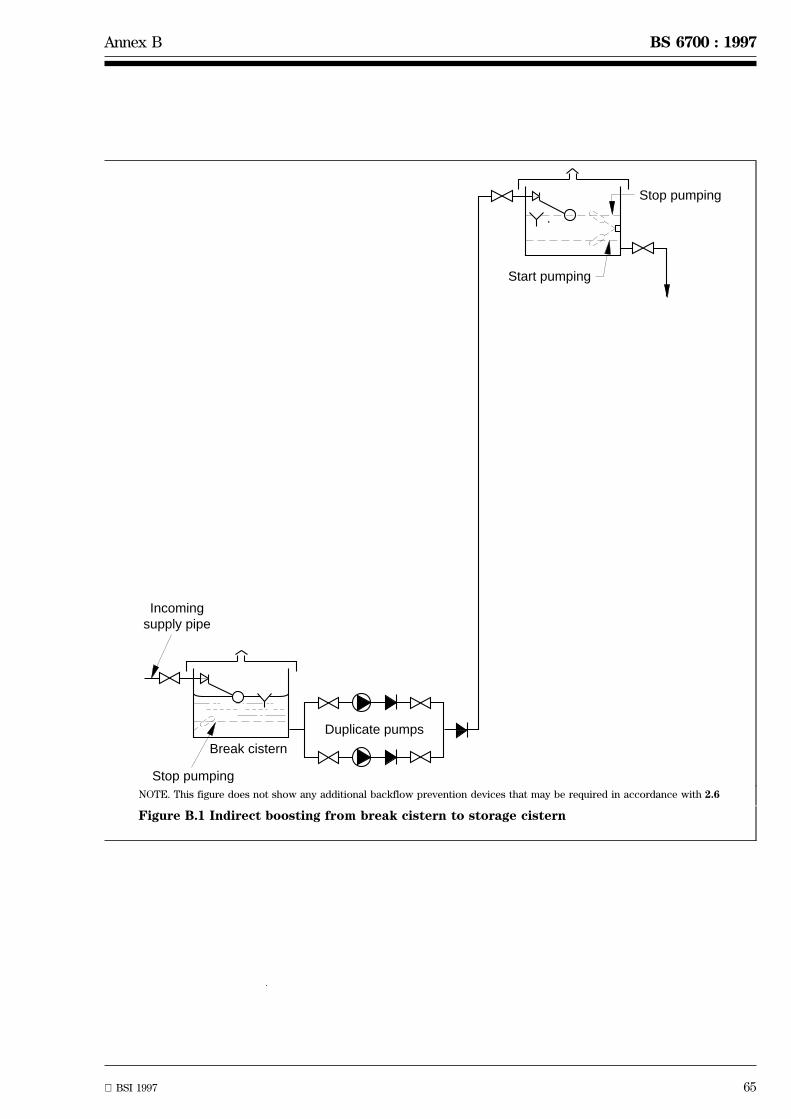
BSI 1997 65
Annex B BS 6700 : 1997
Duplicate pumps
Stop pumping
Start pumping
Stop pumping
Break cistern
Incomingsupply pipe
NOTE. This figure does not show any additional backflow prevention devices that may be required in accordance with 2.6
Figure B.1 Indirect boosting from break cistern to storage cistern

66 BSI 1997
BS 6700 : 1997 Annex B
Duplicate pumps
Stop pumpingBreak cistern
Incomingsupply pipe
Drinking watersupplies to sinksin flats taken fromunboosted supply pipe where mainspressure issufficient
Drinking watersupplies to sinksin flats taken fromboosted supply pipe
Storage cisternsin flats
To pressureswitches
Air line fromcompressor
Level switch
Pressure reliefvalve
Pressuregauge
Boostedsupply
Unboostedsupply
Sight gauge
Stop pumping
Start pumping
Drain tap
NOTE. This figure does not show any additional backflow prevention devices that may be required in accordance with 2.6
Figure B.2 Indirect boosting with pressure vessel
B.3 Indirect boosting with pressure vessel
In buildings where a boosted supply serves a numberof delivery points or storage cisterns at various levels,e.g. in flats, it may not be practicable to control thepumps by means of a number of level switches.
An alternative method of control is by use of apneumatic pressure vessel which contains both air andwater under pressure (see figure B.2). Normally thepressure vessel, pumps and air compressor, togetherwith all control equipment are purchased as apackaged pressure set.

BSI 1997 67
Annex B BS 6700 : 1997
Duplicate pumps
Incomingsupply pipe
Stop pumping
Start pumping
NOTE. This figure does not show any additional backflow prevention devices that may be required in accordancewith 2.6
Figure B.3 Direct boosting
B.4 Direct boosting
Where the water supplier has given prior writtenpermission, pumps are connected to the incomingsupply pipe to enable the pressure head to beincreased (see figure B.3).

68 BSI 1997
BS 6700 : 1997 Annex B
B.5 Direct boosting with drinking water header
The provision of supply drinking water points at highlevel when the pump is not running, where required,may be achieved by a pipe arrangement of limitedcapacity called a header (see figure B.4). Levelswitches should be provided to control the filling ofthe cold water storage cisterns for non-drinking water.Excessive pressures should not be generated, sincehigh pressures at draw-off points cause splashing andwaste of water when taps are opened. The boostingpumps are controlled in two ways:
a) by the emptying of, or drop in level of, the waterin the header; and
b) by the fall of the level of water in one of thestorage cisterns.
The cold water main header should be sized on thebasis of providing 5 l to 7 l per day per dwelling servedand the rising pipe from the header should be providedwith an automatic air inlet valve to allow air to enterand be vented from the header.
B.6 Pumps and equipment
Electrically-driven centrifugal pumping plant isnormally used. Where prudent, provision should bemade for the pumps to be supplied by an alternativeelectricity supply in the event of mains failure.
Pumps should be installed in duplicate and usedalternately. They should be sized so that each pump iscapable of overcoming the static lift plus the frictionlosses in the pipework and valves. All pipeworkconnections to and from pumps should be adequatelysupported and anchored against thrust to avoid stresson pump casings and to ensure proper alignment.
Transmission of pump and motor noise can be reducedby the use of flexible connections and anti-vibrationmountings or pads. Small-power motors of the squirrelcage induction type are suitable for most installations.Care should be taken in pump and pipe sizing tominimize the risk of water-hammer due to surge whenpumps are started and stopped.
B.7 Maintenance and inspection
A responsible person should oversee the properexecution of the scheme and the user should arrangefor regular maintenance and inspection of the pumpsand plant.
All work conducted and inspections made should berecorded in a suitable log book which should be keptin the plant room
COMMENTARY AND RECOMMENDATIONS ON B.7
Attention is drawn to to Health and Safety at WorkAct 1974 with respect to the inspection of pumps andplant.
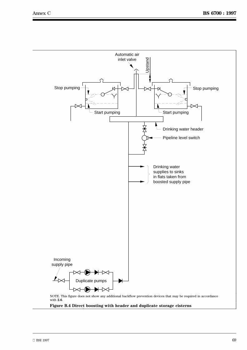
BSI 1997 69
Annex C BS 6700 : 1997
Duplicate pumps
Stop pumpingStop pumping
Start pumping Start pumping
Drinking water header
Pipeline level switch
Incomingsupply pipe
Ups
tand
Automatic airinlet valve
Drinking watersupplies to sinksin flats taken fromboosted supply pipe
NOTE. This figure does not show any additional backflow prevention devices that may be required in accordancewith 2.6.
Figure B.4 Direct boosting with header and duplicate storage cisterns
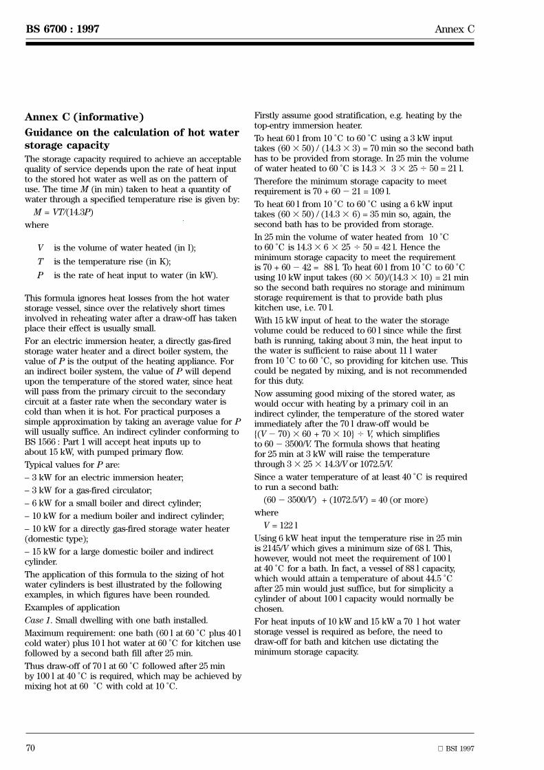
70 BSI 1997
BS 6700 : 1997 Annex C
Annex C (informative)
Guidance on the calculation of hot waterstorage capacityThe storage capacity required to achieve an acceptablequality of service depends upon the rate of heat inputto the stored hot water as well as on the pattern ofuse. The time M (in min) taken to heat a quantity ofwater through a specified temperature rise is given by:
M = VT/(14.3P)
where
V is the volume of water heated (in l);
T is the temperature rise (in K);
P is the rate of heat input to water (in kW).
This formula ignores heat losses from the hot waterstorage vessel, since over the relatively short timesinvolved in reheating water after a draw-off has takenplace their effect is usually small.
For an electric immersion heater, a directly gas-firedstorage water heater and a direct boiler system, thevalue of P is the output of the heating appliance. Foran indirect boiler system, the value of P will dependupon the temperature of the stored water, since heatwill pass from the primary circuit to the secondarycircuit at a faster rate when the secondary water iscold than when it is hot. For practical purposes asimple approximation by taking an average value for Pwill usually suffice. An indirect cylinder conforming toBS 1566 : Part 1 will accept heat inputs up toabout 15 kW, with pumped primary flow.
Typical values for P are:
± 3 kW for an electric immersion heater;
± 3 kW for a gas-fired circulator;
± 6 kW for a small boiler and direct cylinder;
± 10 kW for a medium boiler and indirect cylinder;
± 10 kW for a directly gas-fired storage water heater(domestic type);
± 15 kW for a large domestic boiler and indirectcylinder.
The application of this formula to the sizing of hotwater cylinders is best illustrated by the followingexamples, in which figures have been rounded.
Examples of application
Case 1. Small dwelling with one bath installed.
Maximum requirement: one bath (60 l at 60 ÊC plus 40 lcold water) plus 10 l hot water at 60 ÊC for kitchen usefollowed by a second bath fill after 25 min.
Thus draw-off of 70 l at 60 ÊC followed after 25 minby 100 l at 40 ÊC is required, which may be achieved bymixing hot at 60 ÊC with cold at 10 ÊC.
Firstly assume good stratification, e.g. heating by thetop-entry immersion heater.
To heat 60 l from 10 ÊC to 60 ÊC using a 3 kW inputtakes (603 50) / (14.33 3) = 70 min so the second bathhas to be provided from storage. In 25 min the volumeof water heated to 60 ÊC is 14.33 33 254 50 = 21 l.
Therefore the minimum storage capacity to meetrequirement is 70 + 602 21 = 109 l.
To heat 60 l from 10 ÊC to 60 ÊC using a 6 kW inputtakes (603 50) / (14.33 6) = 35 min so, again, thesecond bath has to be provided from storage.
In 25 min the volume of water heated from 10 ÊCto 60 ÊC is 14.33 6 3 25 4 50 = 42 l. Hence theminimum storage capacity to meet the requirementis 70 + 602 42 = 88 l. To heat 60 l from 10 ÊC to 60 ÊCusing 10 kW input takes (603 50)/(14.33 10) = 21 minso the second bath requires no storage and minimumstorage requirement is that to provide bath pluskitchen use, i.e. 70 l.
With 15 kW input of heat to the water the storagevolume could be reduced to 60 l since while the firstbath is running, taking about 3 min, the heat input tothe water is sufficient to raise about 11 l waterfrom 10 ÊC to 60 ÊC, so providing for kitchen use. Thiscould be negated by mixing, and is not recommendedfor this duty.
Now assuming good mixing of the stored water, aswould occur with heating by a primary coil in anindirect cylinder, the temperature of the stored waterimmediately after the 70 l draw-off would be{(V2 70)3 60 + 703 10} 4 V, which simplifiesto 602 3500/V. The formula shows that heatingfor 25 min at 3 kW will raise the temperaturethrough 33 253 14.3/V or 1072.5/V.
Since a water temperature of at least 40 ÊC is requiredto run a second bath:
(602 3500/V) + (1072.5/V) = 40 (or more)
where
V = 122 l
Using 6 kW heat input the temperature rise in 25 minis 2145/V which gives a minimum size of 68 l. This,however, would not meet the requirement of 100 lat 40 ÊC for a bath. In fact, a vessel of 88 l capacity,which would attain a temperature of about 44.5 ÊCafter 25 min would just suffice, but for simplicity acylinder of about 100 l capacity would normally bechosen.
For heat inputs of 10 kW and 15 kW a 70 l hot waterstorage vessel is required as before, the need todraw-off for bath and kitchen use dictating theminimum storage capacity.
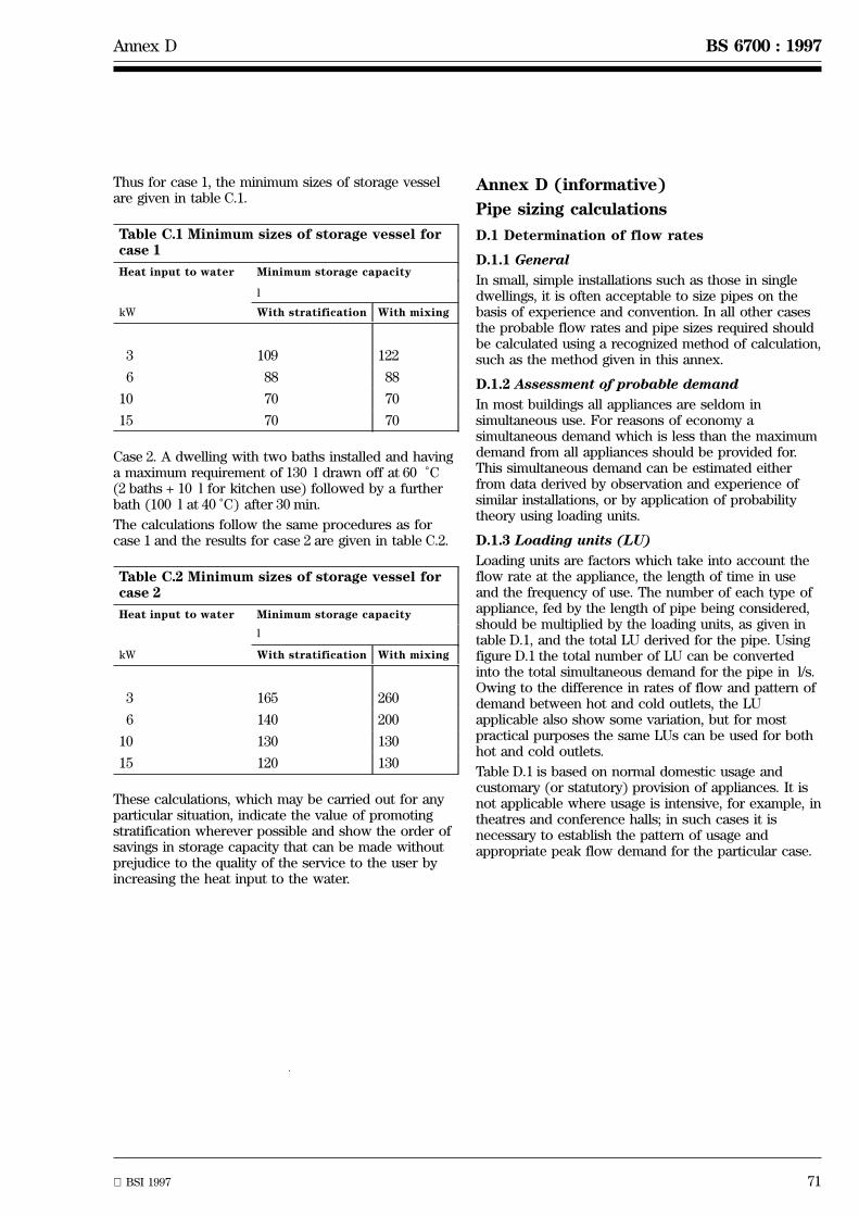
BSI 1997 71
Annex D BS 6700 : 1997
Thus for case 1, the minimum sizes of storage vesselare given in table C.1.
Table C.1 Minimum sizes of storage vessel forcase 1
Heat input to water Minimum storage capacity
l
kW With stratification With mixing
3 109 122
6 88 88
10 70 70
15 70 70
Case 2. A dwelling with two baths installed and havinga maximum requirement of 130 l drawn off at 60 ÊC(2 baths + 10 l for kitchen use) followed by a furtherbath (100 l at 40 ÊC) after 30 min.
The calculations follow the same procedures as forcase 1 and the results for case 2 are given in table C.2.
Table C.2 Minimum sizes of storage vessel forcase 2
Heat input to water Minimum storage capacity
l
kW With stratification With mixing
3 165 260
6 140 200
10 130 130
15 120 130
These calculations, which may be carried out for anyparticular situation, indicate the value of promotingstratification wherever possible and show the order ofsavings in storage capacity that can be made withoutprejudice to the quality of the service to the user byincreasing the heat input to the water.
Annex D (informative)
Pipe sizing calculations
D.1 Determination of flow rates
D.1.1 General
In small, simple installations such as those in singledwellings, it is often acceptable to size pipes on thebasis of experience and convention. In all other casesthe probable flow rates and pipe sizes required shouldbe calculated using a recognized method of calculation,such as the method given in this annex.
D.1.2 Assessment of probable demand
In most buildings all appliances are seldom insimultaneous use. For reasons of economy asimultaneous demand which is less than the maximumdemand from all appliances should be provided for.This simultaneous demand can be estimated eitherfrom data derived by observation and experience ofsimilar installations, or by application of probabilitytheory using loading units.
D.1.3 Loading units (LU)
Loading units are factors which take into account theflow rate at the appliance, the length of time in useand the frequency of use. The number of each type ofappliance, fed by the length of pipe being considered,should be multiplied by the loading units, as given intable D.1, and the total LU derived for the pipe. Usingfigure D.1 the total number of LU can be convertedinto the total simultaneous demand for the pipe in l/s.Owing to the difference in rates of flow and pattern ofdemand between hot and cold outlets, the LUapplicable also show some variation, but for mostpractical purposes the same LUs can be used for bothhot and cold outlets.
Table D.1 is based on normal domestic usage andcustomary (or statutory) provision of appliances. It isnot applicable where usage is intensive, for example, intheatres and conference halls; in such cases it isnecessary to establish the pattern of usage andappropriate peak flow demand for the particular case.

72 BSI 1997
BS 6700 : 1997 Annex D
30
25
20
15
10
8
6
5
4
3
2
1.5
1.0
0.8
0.6
0.5
0.4
0.3
8000
5000
2000
1000
500
400
300
200
100
50
20
10
Load
ing
units
Des
ign
flow
rat
e, li
tre
per
seco
nd
Figure D.1 Conversion ofloading units to designflow rate
Table D.1 Loading units (hot or cold supply)
Type of appliance Loadingunits
WC flushing cistern 2
Wash basin - DN 151
2 1.5 to 3
Bath tap - DN 203
4 10
Bath tap 1 - DN 25 22
Shower 3
Sink tap - DN 151
2 3
Sink tap - DN 203
4 5
Domestic clothes or dishwashing
machines - DN 151
2 3
NOTE 1. WC cisterns with either single or dual flush controlhave the same LU.
NOTE 2. The wash basin LU is for use where pillar taps areinstalled. The larger LU is applicable to situations such asschools and those offices where there is a peak period of use.Where spray taps are installed, an equivalent continuous demandof 0.04 l/s should be assumed.
NOTE 3. Urinal cistern demand is very low, and is normallydisregarded.
NOTE 4. Outlet fittings for industrial purposes or requiring highpeak demands, should be taken into account by adding 100 % oftheir flow rate to the simultaneous demand for other appliancesobtained by using LUs.
D.2 Pressure losses in pipes and fittings
D.2.1 Pipes and pipe fittings
Pressure, or head, losses due to resistance of pipes andfittings at various flows are published in the form oftables for pipes of different materials by the variouspipe manufacturers organizations. A nomogramshowing pressure losses and flows of water at atemperature of 10 ÊC through pipes, based on Lamont'ssmooth pipe formula S3, is shown in figure D.2.
Typical values for equivalent pipe lengths for elbowsand tees are shown in table D.3.
D.2.2 Draw-off taps
The residual head available at each tap or outlet fittingshould be at least equal to the loss of head through thetap at the design flow rate. Alternatively, the loss ofhead may be expressed as an equivalent length of pipe.Some typical losses for low pressure taps are shown intable D.2.

An
nex
DB
S6700
:1997
B
SI
1997
73
Wall friction gradient (head loss) in kPa per metre
Velocity, metres per second
1 0.8 0.6 0.5 0.4 0.3
0.2
0.1
2
5 4 3
0.001
0.002
0.003 0.004 0.005 0.006
0.008
0.02
0.01
0.03 0.04 0.05 0.06 0.07 0.08
6
8 10
8 12
10 15 18 22 28 35302520
15105 35 40 45 50
55 60 70 807565
42 54
67
76.1
3 22.5
1.5
1.0
0.5
0.1
0.75
0.25
4 6 5
6
1.00.80.60.50.40.30.2 2 3 5 4 6 8 2010 5030 40
0.10.080.060.05
Flow, litres per second
Formula applicable between these limits only
Actual bore of pipe, millimetres
Outside diameter of copper tube to table X of BS 2871: Part 1: 1971, millimetres
Lamont's smooth pipe formula S3
where: v is the velocity (m/s): d is the diameter (mm); i is the hydraulic gradient;
and R = 10
where: R is the wall friction gradient (kPa)
0.5545 dv 1.7715
0.6935
v = 0.5545 d 0.6935 0.5645i
Figure D.2 Determination of pipe diameter: (water at 10 ÊC)
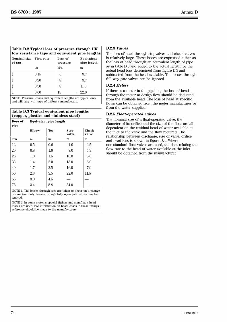
74 BSI 1997
BS 6700 : 1997 Annex D
Table D.2 Typical loss of pressure through UKlow resistance taps and equivalent pipe lengths
Nominal size
of tap
Flow rate Loss of
pressure
Equivalent
pipe length
l/s kPa m
1
2 0.15 5 3.71
2 0.20 8 3.73
4 0.30 8 11.8
1 0.60 15 22.0
NOTE. Pressure losses and equivalent lengths are typical onlyand will vary with taps of different manufacture.
Table D.3 Typical equivalent pipe lengths(copper, plastics and stainless steel)
Bore of
pipe
Equivalent pipe length
Elbow Tee Stopvalve
Checkvalve
mm m m m m
12 0.5 0.6 4.0 2.5
20 0.8 1.0 7.0 4.3
25 1.0 1.5 10.0 5.6
32 1.4 2.0 13.0 6.0
40 1.7 2.5 16.0 7.9
50 2.3 3.5 22.0 11.5
65 3.0 4.5 Ð Ð
73 3.4 5.8 34.0 Ð
NOTE 1. The losses through tees are taken to occur on a changeof direction only. Losses through fully open gate valves may beignored.
NOTE 2. In some systems special fittings and significant headlosses are used. For information on head losses in these fittings,reference should be made to the manufacturers.
D.2.3 Valves
The loss of head through stopvalves and check valvesis relatively large. These losses are expressed either asthe loss of head through an equivalent length of pipeas in table D.3 and added to the actual length, or theactual head loss determined from figure D.3 andsubtracted from the head available. The losses throughfull way gate valves can be ignored.
D.2.4 Meters
If there is a meter in the pipeline, the loss of headthrough the meter at design flow should be deductedfrom the available head. The loss of head at specificflows can be obtained from the meter manufacturer orfrom the water supplier.
D.2.5 Float-operated valves
The nominal size of a float-operated valve, thediameter of its orifice and the size of the float are alldependent on the residual head of water available atthe inlet to the valve and the flow required. Therelationship between discharge, size of valve, orificeand head loss is shown in figure D.4. Wherenon-standard float valves are used, the data relating theflow rate to the head of water available at the inletshould be obtained from the manufacturer.

BSI 1997 75
Annex D BS 6700 : 1997
Hea
d lo
ss, k
Pa
0.5
0.6
0.7
0.8 0.9 1.0
Flo
w, l
itre
per
seco
nd
0.03
0.04
0.05
0.060.07
0.090.08
0.1
0.2
0.3
0.4
0.5
0.6
0.8 0.9 1.0
2
3
4
5
6 7 8 9 10
0.7
2
4
6
8
10
20
30
40
60
3
80
Nom
inal
siz
e of
sto
pval
ve
2
1
1
1
3/4
1/4
1/2
1/2
Figure D.3 Head loss through stopvalves
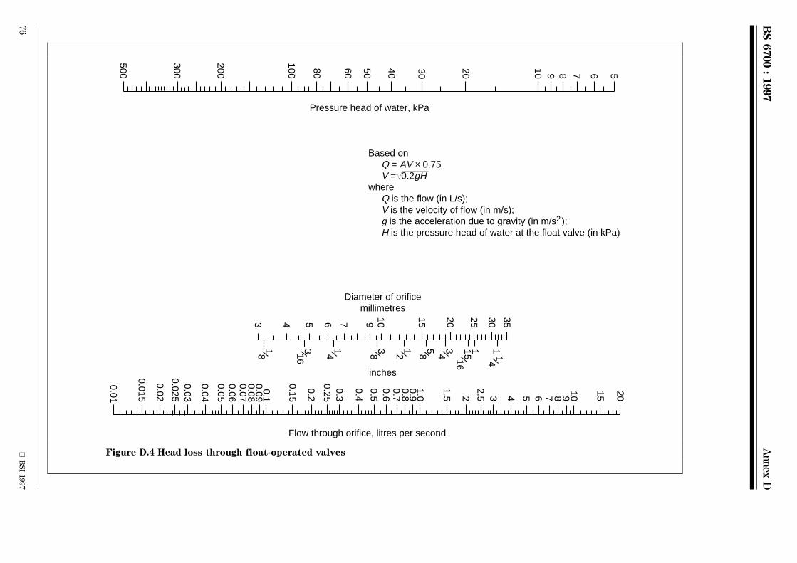
BS
6700
:1997
An
nex
D
76
BS
I1997
Pressure head of water, kPa
Diameter of orificemillimetres
inches
1
40
60
50
80
500
300
200
100
30
8 9 10
20
7
5
6
Flow through orifice, litres per second
0.01
0.015
0.02
0.03
0.04
0.05
0.25
0.06 0.07 0.08
0.1 0.09
0.4
0.5 0.6
0.8 0.7
1.5
2.5
0.9 1.0
0.3
0.2
0.15
0.025
6 7 8 9 10
15
20
5
4
3
2
3/81/8 1/43/16 1/4
115/16
1/2 5/8 3/4
5 6 7 9 10 15 20 25
30 3543
Based on Q = AV × 0.75 V = 0.2gH where Q is the flow (in L/s); V is the velocity of flow (in m/s); g is the acceleration due to gravity (in m/s ); H is the pressure head of water at the float valve (in kPa)
2
Figure D.4 Head loss through float-operated valves

BSI 1997 77
Annex D BS 6700 : 1997
D.3 Available head
D.3.1 Systems supplied from storage cisterns
The initial available head should normally be measuredfrom the outlet of a cistern, unless the incoming supplyis sufficient to allow a depth of half the cisternor 0.5 m, whichever is less to be assumed. Each pipelength between pipe junctions should be sized on atrial and error basis, starting with the first length ofpipe from the cistern. The residual head at the end ofeach pipe length should be calculated taking accountof head losses in pipework, fittings and valves. If aresidual head is arrived at that is negative or less thanthe head absorbed by the outlet or tap, of if animpractical pipe size is indicated, the diameter of thepreceding pipes should be adjusted and the procedurerepeated.
D.3.2 Systems supplied from the supply pipe(mains pressure)
The minimum pressure in the main at the time of peakdemand should be obtained from the water supplierand if there is any doubt about the pressure beingobtainable in the future a suitable factor should beapplied. Once the minimum pressure has beenestablished the method for pipe sizing is identical withthat indicated in D.4.1.
D.4 Determination of pipe sizes
D.4.1 General
The principle underlying design of a water supplysystem is the same whether cold and hot watersupplies to appliances are obtained from a storagecistern or direct from a main service pipe. Frictionlosses in the pipes may be determined by the generaltheory or roughness, but this has too many variablesfor normal design purposes. Exponential formulae havebeen devised, which relate pipe diameter to head loss,water velocity and flow for new pipes in smooth-borematerials. Reduction in capacity with age can beignored for pipe sizing calculations for pipes carryingclean portable water within buildings. Using flowcharts which are based on exponential formulae, apipe diameter can be selected which meets the otherthree design parameters of design flow, maximumwater velocity and permissible head loss.
D.4.2 Calculation diagrams
An approximate isometric or similar projection of thescheme should be drawn. This drawing should be toscale to facilitate measurement of pipe lengths andlevels unless the data can be obtained otherwise. Thepossibility of future extensions or additions to thescheme should be considered at this stage. Each pipejunction and fitting should be numbered for calculationpurposes and pipes referenced by their terminaljunctions and fittings.
D.4.3 Calculation sheet
A calculation sheet should be used on which thefollowing data can be entered (see attached calculationsheets D.4 and D.5):
a) pipe reference;
b) total demand in loading units (LU);
c) simultaneous demand or design flow rate (in l/s);
d) pipe diameter (in mm);
e) velocity (in m/s);
f) head or pressure loss R (in kPa/m);
g) loss of head (in kPa) due to drop or rise, that is,the difference in level of inlet and outlet;
h) available head (in kPa) at outlet end of pipelength;
i) actual pipe length (in m);
j) equivalent pipe length (in m), that is, the actualplus an allowance for fittings;
k) head loss (in kPa) due to pipe and pipe fittings;
l) head loss (in kPa) due to valves etc.;
m) total head loss (in kPa);
n) available residual head (in kPa) at outlet of pipelength;
o) appliance or fitting type (bath, sink, etc.);
p) required residual head for fitting (in kPa);
q) surplus head (in kPa).
D.4.4 Alterations and extensions
Where an extension or alteration is carried out to oldpipework, the existing pipes may be of imperial sizes,and the calculations should be adjusted accordingly.
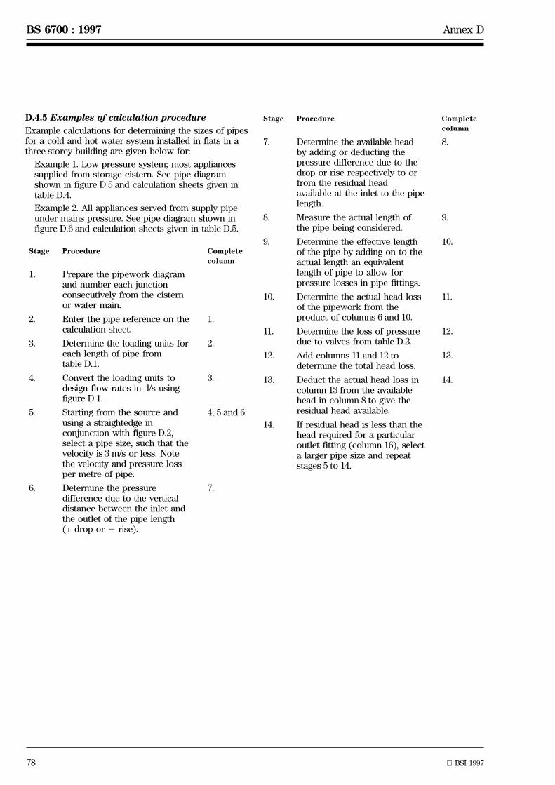
78 BSI 1997
BS 6700 : 1997 Annex D
D.4.5 Examples of calculation procedure
Example calculations for determining the sizes of pipesfor a cold and hot water system installed in flats in athree-storey building are given below for:
Example 1. Low pressure system; most appliancessupplied from storage cistern. See pipe diagramshown in figure D.5 and calculation sheets given intable D.4.
Example 2. All appliances served from supply pipeunder mains pressure. See pipe diagram shown infigure D.6 and calculation sheets given in table D.5.
Stage Procedure Complete
column
1. Prepare the pipework diagramand number each junctionconsecutively from the cisternor water main.
2. Enter the pipe reference on thecalculation sheet.
1.
3. Determine the loading units foreach length of pipe fromtable D.1.
2.
4. Convert the loading units todesign flow rates in l/s usingfigure D.1.
3.
5. Starting from the source andusing a straightedge inconjunction with figure D.2,select a pipe size, such that thevelocity is 3 m/s or less. Notethe velocity and pressure lossper metre of pipe.
4, 5 and 6.
6. Determine the pressuredifference due to the verticaldistance between the inlet andthe outlet of the pipe length(+ drop or 2 rise).
7.
Stage Procedure Complete
column
7. Determine the available headby adding or deducting thepressure difference due to thedrop or rise respectively to orfrom the residual headavailable at the inlet to the pipelength.
8.
8. Measure the actual length ofthe pipe being considered.
9.
9. Determine the effective lengthof the pipe by adding on to theactual length an equivalentlength of pipe to allow forpressure losses in pipe fittings.
10.
10. Determine the actual head lossof the pipework from theproduct of columns 6 and 10.
11.
11. Determine the loss of pressuredue to valves from table D.3.
12.
12. Add columns 11 and 12 todetermine the total head loss.
13.
13. Deduct the actual head loss incolumn 13 from the availablehead in column 8 to give theresidual head available.
14.
14. If residual head is less than thehead required for a particularoutlet fitting (column 16), selecta larger pipe size and repeatstages 5 to 14.

BSI 1997 79
Annex D BS 6700 : 1997
H6H7
C4C5
H4H2
C1 H1
C2 C3H3 H5
6 C6
4
57
�������������
1
Minimum pressure in water mainfor this example = 30 m head
3
�������������Sink Wash
basinBath
WC
2
��������������������������
Cold waterstoragecistern
Hot watercylinder
NOTE. This drawing is for pipe sizing example only and does not include all necessary valves and backflow prevention devices.
Figure D.5 Example of pipe sizing for hot and cold water services, low pressure system

80 BSI 1997
BS 6700 : 1997 Annex D
H4H5
10
89
H2
H1 H3
11
65 7
4
��������������������������3
T
��������������������������2
1�������������
WashbasinWCSink
Bath
Hot water cylinder with check valve, expansion valve, expansion vessel and thermostatic relief valve,as clause 2.4
Minimum pressure in water mainfor this example = 30 m head
T
T
NOTE. This drawing is for pipe sizing example only and does not include all necessary valves and backflow prevention devices.
Figure D.6 Example of pipe sizing for hot and cold water services, mains pressuresystem

An
nex
DB
S6700
:1997
B
SI
1997
81
Table D.4 Example of pipe sizing calculations for cold water services1)
Pipe Flow rate Pipe Velocity Head Drop + Available Pipe length Head loss Residual head
reference Total Design size v loss R Rise2 head(7 + 14)
Actual Effective Pipe(10 3 6)
Valves2) Total(11 + 12)
Available(8 2 13)
Fittingtype
Required Surplus
m LU l/s DN m/s kPa/m kPa kPa m m kPa kPa kPa kPa kPa kPa
1 2 3 4 5 6 7 8 9 10 11 12 13 14 15 16 17
Main service pipe - for this example the minimum head in main = 300 kPa (3 bar)
12 2 9 + list 0.6 + 0.3 =0.9
28 1.7 1.4 2 50 250 25 35 49 2 SV= 21
70 180
22 3 6 + list 0.4 + 0.2 =0.6
22 2.0 2.5 2 30 150 3 4.2 11 11 139
32 4 3 + list 0.2 + 0.1 =0.3
15 2.2 5 2 30 109 3 4.2 21 21 88
42 5 3 + list 0.3 15 2.2 5 + 10 98 1 1.4 7 SV = 18 25 73
5 2 6 0.2 15 1.5 2.3 + 10 83 6 8.4 20 20 63 sink 5 58
52 7 0.1 15 0.75 0.6 2 5 68 1 1.4 1 1 67 float 30 37
valve
(5 mm f)
Cold water distributing pipes in flats
C12 C2 13.5 0.35 28 0.63 0.25 +20 20 4 5.6 1.4 Gatevalve
1.4 18.6
= 0
C22 C3 11.5 0.32 22 1 0.8 Ð 18.6 1 1.4 1.2 1.2 17.4
C32 C4 10.0 0.30 22 0.9 0.65 2 6 11.4 1.5 2.1 1.4 1.4 10 bath 8 2
C32 C5 1.5 0.15 15 1.1 1.3 2 7 10.4 0.7 1.0 1.3 1.3 9.1 wash 8 1.1
basin
C2 2 C6 2.0 0.10 15 0.7 0.6 27 11.6 1 1.4 0.9 0.9 10.7 WC 10 0.7
cistern
(6.5 mmf)

BS
6700
:1997
An
nex
D
82
BS
I1997
Table D.4 Example of pipe sizing calculations for cold water services1) (continued)
Pipe Flow rate Pipe Velocity Head Drop + Available Pipe length Head loss Residual head
reference Total Design size v loss R Rise2 head(7 + 14)
Actual Effective Pipe(10 3 6)
Valves2) Total(11 + 12)
Available(8 2 13)
Fittingtype
Required Surplus
m LU l/s DN m/s kPa/m kPa kPa m m kPa kPa kPa kPa kPa kPa
1 2 3 4 5 6 7 8 9 10 11 12 13 14 15 16 17
Hot water distributing pipes in flats
H12 H2 14.5 0.37 28 0.75 0.3 + 10 10 4.0 5.6 1.7 Gatevalve= 0
1.7 8.3
H22 H3 14.5 0.37 28 0.75 0.3 + 10 18.3 1.5 2.1 0.6 0.6 17.7
H3 2 H4 3.0 0.20 22 0.65 0.31 2 10 7.7 3.0 4.2 1.3 1.3 6.4 sink 5 1.4
H32 H5 11.5 0.32 28 0.65 0.24 17.7 3.0 4.2 1.0 1.0 16.7
H5 2 H6 10.0 0.30 22 0.9 0.65 2 6 10.7 1.5 2.1 1.4 1.4 9.3 bath 8 1.3
H52 H7 1.5 0.15 15 1.1 1.3 2 7 9.7 0.7 1.0 1.3 1.3 8.4 washbasin
5 3.4
Charts used based on figure A.2.5 (water at 10 ÊC)
1) Cistern supply-except for DW at sink
2)SV = stopvalve CV = check valve DCV = Double check valve 1 kPa = 0.1 metre head = 0.01 bar
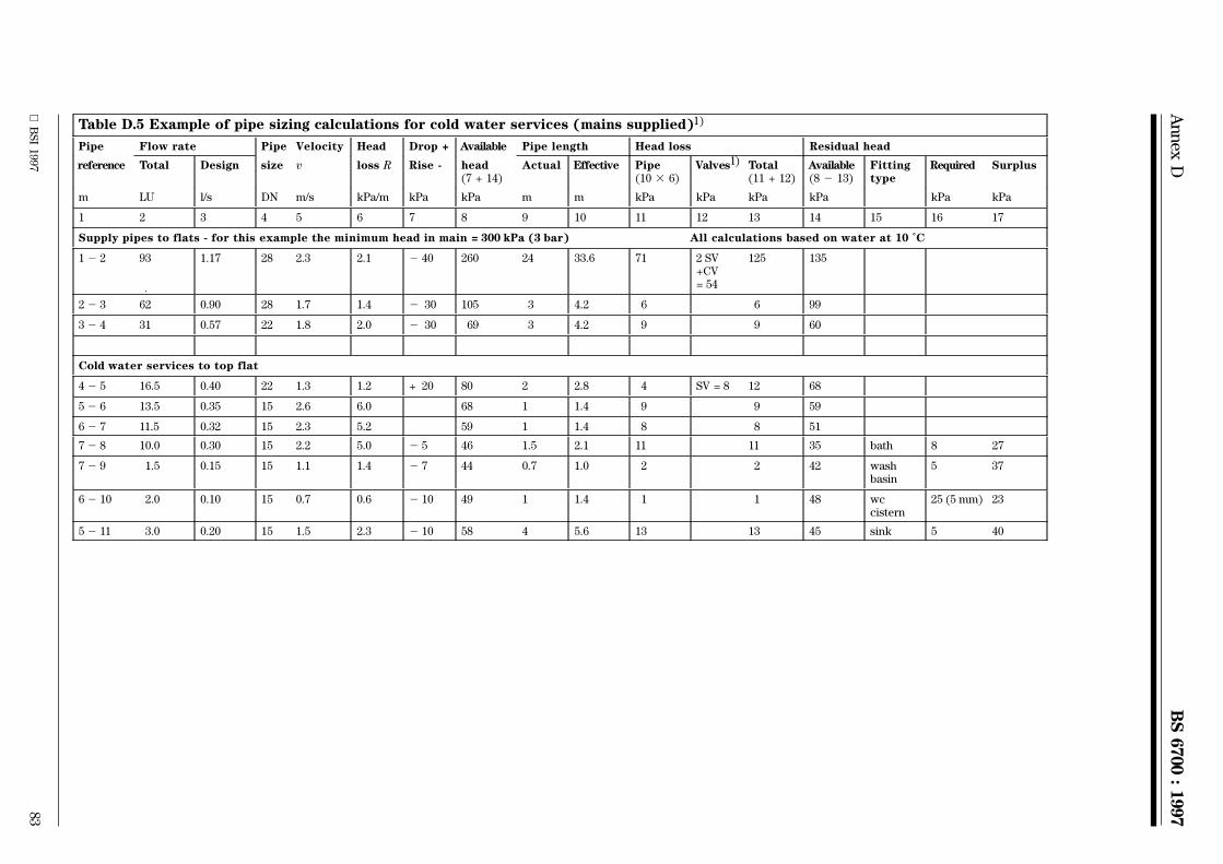
An
nex
DB
S6700
:1997
B
SI
1997
83
Table D.5 Example of pipe sizing calculations for cold water services (mains supplied)1)
Pipe Flow rate Pipe Velocity Head Drop + Available Pipe length Head loss Residual head
reference Total Design size v loss R Rise - head(7 + 14)
Actual Effective Pipe(10 3 6)
Valves1) Total(11 + 12)
Available(8 2 13)
Fittingtype
Required Surplus
m LU l/s DN m/s kPa/m kPa kPa m m kPa kPa kPa kPa kPa kPa
1 2 3 4 5 6 7 8 9 10 11 12 13 14 15 16 17
Supply pipes to flats - for this example the minimum head in main = 300 kPa (3 bar) All calculations based on water at 10 ÊC
12 2 93 1.17 28 2.3 2.1 2 40 260 24 33.6 71 2 SV+CV= 54
125 135
22 3 62 0.90 28 1.7 1.4 2 30 105 3 4.2 6 6 99
32 4 31 0.57 22 1.8 2.0 2 30 69 3 4.2 9 9 60
Cold water services to top flat
42 5 16.5 0.40 22 1.3 1.2 + 20 80 2 2.8 4 SV = 8 12 68
52 6 13.5 0.35 15 2.6 6.0 68 1 1.4 9 9 59
62 7 11.5 0.32 15 2.3 5.2 59 1 1.4 8 8 51
72 8 10.0 0.30 15 2.2 5.0 2 5 46 1.5 2.1 11 11 35 bath 8 27
72 9 1.5 0.15 15 1.1 1.4 2 7 44 0.7 1.0 2 2 42 washbasin
5 37
62 10 2.0 0.10 15 0.7 0.6 2 10 49 1 1.4 1 1 48 wccistern
25 (5 mm) 23
52 11 3.0 0.20 15 1.5 2.3 2 10 58 4 5.6 13 13 45 sink 5 40
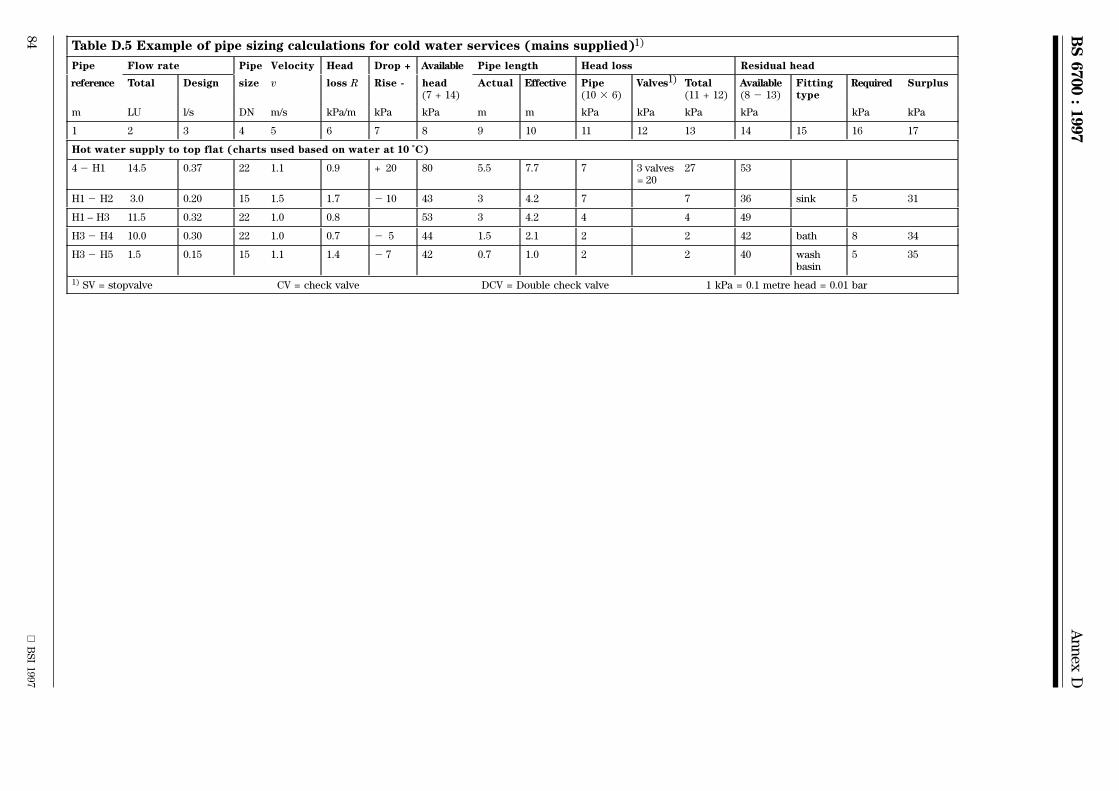
BS
6700
:1997
An
nex
D
84
BS
I1997
Table D.5 Example of pipe sizing calculations for cold water services (mains supplied)1)
Pipe Flow rate Pipe Velocity Head Drop + Available Pipe length Head loss Residual head
reference Total Design size v loss R Rise - head(7 + 14)
Actual Effective Pipe(10 3 6)
Valves1) Total(11 + 12)
Available(8 2 13)
Fittingtype
Required Surplus
m LU l/s DN m/s kPa/m kPa kPa m m kPa kPa kPa kPa kPa kPa
1 2 3 4 5 6 7 8 9 10 11 12 13 14 15 16 17
Hot water supply to top flat (charts used based on water at 10 ÊC)
42 H1 14.5 0.37 22 1.1 0.9 + 20 80 5.5 7.7 7 3 valves= 20
27 53
H12 H2 3.0 0.20 15 1.5 1.7 2 10 43 3 4.2 7 7 36 sink 5 31
H1 ± H3 11.5 0.32 22 1.0 0.8 53 3 4.2 4 4 49
H32 H4 10.0 0.30 22 1.0 0.7 2 5 44 1.5 2.1 2 2 42 bath 8 34
H32 H5 1.5 0.15 15 1.1 1.4 2 7 42 0.7 1.0 2 2 40 washbasin
5 35
1) SV = stopvalve CV = check valve DCV = Double check valve 1 kPa = 0.1 metre head = 0.01 bar
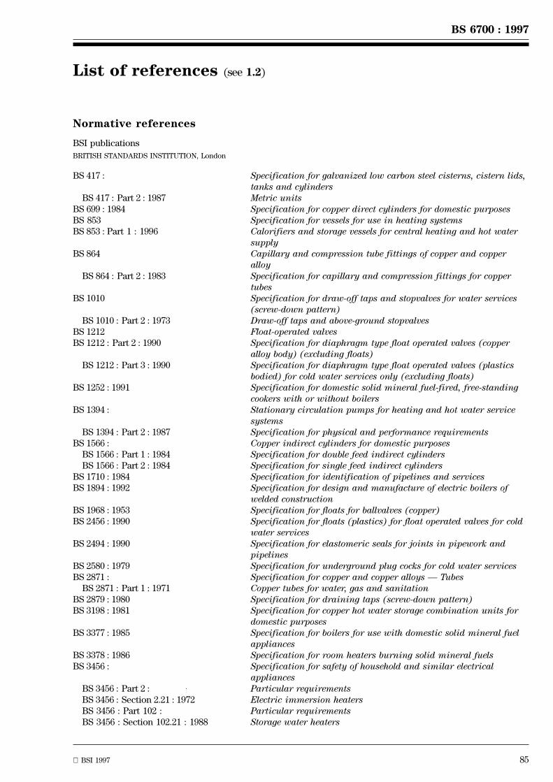
BSI 1997 85
BS 6700 : 1997
List of references (see 1.2)
Normative references
BSI publications
BRITISH STANDARDS INSTITUTION, London
BS 417 : Specification for galvanized low carbon steel cisterns, cistern lids,tanks and cylinders
BS 417 : Part 2 : 1987 Metric unitsBS 699 : 1984 Specification for copper direct cylinders for domestic purposesBS 853 Specification for vessels for use in heating systemsBS 853 : Part 1 : 1996 Calorifiers and storage vessels for central heating and hot water
supplyBS 864 Capillary and compression tube fittings of copper and copper
alloyBS 864 : Part 2 : 1983 Specification for capillary and compression fittings for copper
tubesBS 1010 Specification for draw-off taps and stopvalves for water services
(screw-down pattern)BS 1010 : Part 2 : 1973 Draw-off taps and above-ground stopvalves
BS 1212 Float-operated valvesBS 1212 : Part 2 : 1990 Specification for diaphragm type float operated valves (copper
alloy body) (excluding floats)BS 1212 : Part 3 : 1990 Specification for diaphragm type float operated valves (plastics
bodied) for cold water services only (excluding floats)BS 1252 : 1991 Specification for domestic solid mineral fuel-fired, free-standing
cookers with or without boilersBS 1394 : Stationary circulation pumps for heating and hot water service
systemsBS 1394 : Part 2 : 1987 Specification for physical and performance requirements
BS 1566 : Copper indirect cylinders for domestic purposesBS 1566 : Part 1 : 1984 Specification for double feed indirect cylindersBS 1566 : Part 2 : 1984 Specification for single feed indirect cylinders
BS 1710 : 1984 Specification for identification of pipelines and servicesBS 1894 : 1992 Specification for design and manufacture of electric boilers of
welded constructionBS 1968 : 1953 Specification for floats for ballvalves (copper)BS 2456 : 1990 Specification for floats (plastics) for float operated valves for cold
water servicesBS 2494 : 1990 Specification for elastomeric seals for joints in pipework and
pipelinesBS 2580 : 1979 Specification for underground plug cocks for cold water servicesBS 2871 : Specification for copper and copper alloys Ð Tubes
BS 2871 : Part 1 : 1971 Copper tubes for water, gas and sanitationBS 2879 : 1980 Specification for draining taps (screw-down pattern)BS 3198 : 1981 Specification for copper hot water storage combination units for
domestic purposesBS 3377 : 1985 Specification for boilers for use with domestic solid mineral fuel
appliancesBS 3378 : 1986 Specification for room heaters burning solid mineral fuelsBS 3456 : Specification for safety of household and similar electrical
appliancesBS 3456 : Part 2 : Particular requirementsBS 3456 : Section 2.21 : 1972 Electric immersion heatersBS 3456 : Part 102 : Particular requirementsBS 3456 : Section 102.21 : 1988 Storage water heaters

BS 6700 : 1997
86 BSI 1997
BS 3955 : 1986 Specification for electrical controls for household and similargeneral purposes
BS 4127 : 1994 Specification for light gauge stainless steel tubes, primarily forwater applications
BS 4213 : 1991 Specification for cold water storage and combined feed andexpansion cisterns (polyolefin or olefin copolymer) up to 500 Lcapacity used for domestic purposes
BS 4433 : Domestic solid mineral fuel fired boilers with rated output upto 45 kW
BS 4433 : Part 1 : 1994 Specification for boilers with undergrate ash removalBS 4433 : Part 2 : 1994 Specification for gravity feed boilers designed to burn small
anthraciteBS 4814 : 1990 Specification for expansion vessels using an internal diaphragm,
for sealed hot water heating systemsBS 4834 : 1990 Specification for inset open fires without convection with or
without boilers, burning solid mineral fuelsBS 4876 : 1984 Specification for performance requirements for domestic flued oil
burning appliances (including test procedures)BS 5163 : 1986 Specification for predominantly key-operated cast iron gate valves
for waterworks purposesBS 5258 : Safety of domestic gas appliances
BS 5258 : Part 1 : 1986 Specification for central heating boilers and circulatorsBS 5258 : Part 8 : 1980 Combined appliances: gas fire/back boilerBS 5258 : Part 15 : 1990 Specification for combination boilers
BS 5386 : Specification for gas burning appliancesBS 5386 : Part 1 : 1976 Gas burning appliances for instantaneous production of hot water
for domestic useBS 5386 : Part 2 : 1981 Mini water heaters (2nd and 3rd family gases)BS 5386 : Part 5 : 1988 Specification for gas burning instantaneous water heaters with
automatic output variation (2nd and 3rd family gases)BS 5422 : 1990 Method for specifying thermal insulating materials on pipes,
ductwork and equipment (in the temperature range 240 ÊC to+ 700 ÊC)
BS 5433 : 1976 Specification for underground stopvalves for water servicesBS 5615 : 1985 Specification for insulating jackets for domestic hot water storage
cylindersBS 5728 : Measurement of flow of cold potable water in closed conduits
BS 5728 : Part 1 : 1979 Specification for single metersBS 5871 : Specification for installation of gas fires, convector heaters,
fire/back boilers and decorative fuel effect gas appliancesBS 5871 : Part 1 : 1991 Gas fires, convector heaters and fire/back boilers (1st and 2nd
and 3rd family gases)BS 5918 : 1989 Code of practice for solar heating systems for domestic hot waterBS 6144 : 1990 Specification for expansion vessels using an internal diaphragm,
for unvented hot water supply systemsBS 6280 : 1982 Method of vacuum (backsiphonage) test for water-using appliancesBS 6281 : Devices without moving parts for the prevention of contamination
of water by backflowBS 6281 : Part 1 : 1992 Specification for type A air gapsBS 6281 : Part 2 : 1982 Specification for type B air gapsBS 6281 : Part 3 : 1982 Specification for pipe interrupters of nominal size up to and
including DN 42
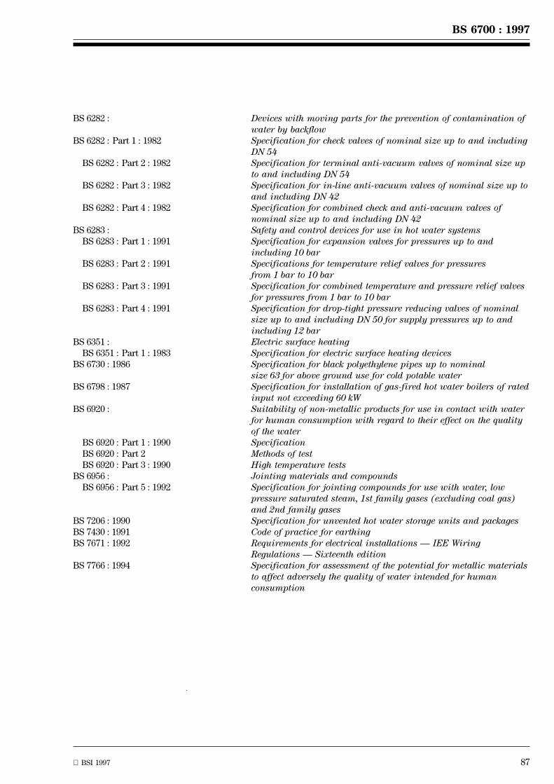
BSI 1997 87
BS 6700 : 1997
BS 6282 : Devices with moving parts for the prevention of contamination ofwater by backflow
BS 6282 : Part 1 : 1982 Specification for check valves of nominal size up to and includingDN 54
BS 6282 : Part 2 : 1982 Specification for terminal anti-vacuum valves of nominal size upto and including DN 54
BS 6282 : Part 3 : 1982 Specification for in-line anti-vacuum valves of nominal size up toand including DN 42
BS 6282 : Part 4 : 1982 Specification for combined check and anti-vacuum valves ofnominal size up to and including DN 42
BS 6283 : Safety and control devices for use in hot water systemsBS 6283 : Part 1 : 1991 Specification for expansion valves for pressures up to and
including 10 barBS 6283 : Part 2 : 1991 Specifications for temperature relief valves for pressures
from 1 bar to 10 barBS 6283 : Part 3 : 1991 Specification for combined temperature and pressure relief valves
for pressures from 1 bar to 10 barBS 6283 : Part 4 : 1991 Specification for drop-tight pressure reducing valves of nominal
size up to and including DN 50 for supply pressures up to andincluding 12 bar
BS 6351 : Electric surface heatingBS 6351 : Part 1 : 1983 Specification for electric surface heating devices
BS 6730 : 1986 Specification for black polyethylene pipes up to nominalsize 63 for above ground use for cold potable water
BS 6798 : 1987 Specification for installation of gas-fired hot water boilers of ratedinput not exceeding 60 kW
BS 6920 : Suitability of non-metallic products for use in contact with waterfor human consumption with regard to their effect on the qualityof the water
BS 6920 : Part 1 : 1990 SpecificationBS 6920 : Part 2 Methods of testBS 6920 : Part 3 : 1990 High temperature tests
BS 6956 : Jointing materials and compoundsBS 6956 : Part 5 : 1992 Specification for jointing compounds for use with water, low
pressure saturated steam, 1st family gases (excluding coal gas)and 2nd family gases
BS 7206 : 1990 Specification for unvented hot water storage units and packagesBS 7430 : 1991 Code of practice for earthingBS 7671 : 1992 Requirements for electrical installations Ð IEE Wiring
Regulations Ð Sixteenth editionBS 7766 : 1994 Specification for assessment of the potential for metallic materials
to affect adversely the quality of water intended for humanconsumption
BS 6700 : 1997
88 BSI 1997
BS EN 257 : 1992 Mechanical thermostats for gas-burning appliancesBS EN 297 : 1994 Gas-fired central heating boilers Ð Type B11 and B11BS boilers fitted
with atmospheric burners of nominal heat input not exceeding 70 kWBS EN 545 : 1995 Ductile iron pipes, fittings, accessories and their joints for water
pipelines Ð Requirements and test methodsBS EN 598 : 1995 Ductile iron pipes, fittings, accessories and their joints for sewerage
applications Ð Requirements and test methodsBS EN 625 : 1996 Gas fired central heating boilers Ð Specific requirements for the
domestic hot water operation of combination boilers of nominal heatinput not exceeding 70 kW.
BS EN 969 : 1996 Specification for ductile iron pipes, fittings, accessories and their jointsfor gas pipelines Ð Requirements and test methods
BS EN 60335 : Specification for safety of household and similar electrical appliancesBS EN 60335-2 Particular requirementsBS EN 60335-2-21 : 1992 Storage water heatersBS EN 60335-2-35 : 1995 Instantaneous water heaters
Other publications
Informative references
BSI publications
BRITISH STANDARDS INSTITUTION, London
BS 534 : 1990 Specification for steel pipes, joints and specials for water andsewage
BS 1387 : 1985 Specification for screwed and socketed steel tubes and tubularsand for plain end steel tubes suitable for welding or for screwingto BS 21 pipe threads
BS 2872 : 1989 Specification for copper and copper alloy forging stock andforgings
BS 2874 : 1986 Specification for copper and copper alloy rods and sections (otherthan forging stock)
BS 3505 : 1986 Specification for unplasticized polyvinyl chloride (PVC-U)pressure pipes for cold potable water
BS 4346 : Joints and fittings for use with unplasticized PVC pressure pipesBS 4346 : Part 1 : 1969 Injection moulded unplasticized PVC fittings for solvent welding
for use with pressure pipes, including potable water supplyBS 4346 : Part 2 : 1970 Mechanical joints and fittings, principally of unplasticized PVCBS 4346 : Part 3 : 1982 Specification for solvent cement
BS 4991 : 1974 Specification for propylene copolymer pressure pipeBS 5114 : 1975 Specification for performance requirements for joints and
compression fittings for use with polyethylene pipesBS 5154 : 1991 Specification for copper alloy globe, globe stop and check, check
and gate valvesBS 5412 : 1996 Specification for low resistance single taps and combination tap
assemblies (nominal size ¯ and � suitable for operation at PN10 max. and a minimum flow pressure of 0.01 MPa (0.1 bar)
BS 5449 : 1990 Specification for forced circulation hot water central heatingsystems for domestic premises
BSI 1997 89
BS 6700 : 1997
BS 5493 : 1977 Code of practice for protective coating of iron and steel structuresagainst corrosion
BS 5546 : 1990 Specification for installation of gas hot water supplies fordomestic purposes (1st, 2nd and 3rd family gases)
BS 5834 : Surface boxes, guards and underground chambers for gas andwaterworks purposes
BS 5834 : Part 2 : 1983 Specification for small surface boxesBS 6340 Shower units
BS 6340 : Part 4 : 1984 Specification for shower heads and related equipmentBS 6437 : 1984 Specification for polyethylene pipes (type 50) in metric diameters
for general purposesBS 6465 : Sanitary installations
BS 6465 : Part 1 : 1994 Code of practice for scale of provision, selection and installation ofsanitary appliances
BS 6572 : 1985 Specification for blue polyethylene pipes up to nominal size 63 forbelow ground use for potable water
BS 7291 Thermoplastics pipes and associated fittings for hot and coldwater for domestic purposes and heating installations inbuildings
BS 7291 : Part 1 : 1990 General requirementsBS 7291 : Part 2 : 1990 Specification for polybutylene (PB) pipes and associated fittingsBS 7291 : Part 3 : 1990 Specification for crosslinked polyethylene (PE-X) pipes and
associated fittingsBS 7291 : Part 4 : 1990 Specification for chlorinated polyvinyl chloride (PVC-C) pipes and
associated fittings and solvent cementCP 312 Code of practice for plastics pipework (thermoplastics material)
CP 312 : Part 1 : 1973 General principles and choice of materialCP 312 : Part 2 : 1973 Unplasticized PVC pipework for the conveyance of liquids under
pressureCP 312 : Part 3 : 1973 Polyethylene pipes for the conveyance of liquids under pressure
CP 342 Code of practice for centralized hot water supplyCP 342 : Part 2 : 1974 Buildings other than individual dwellings
BS EN 200 : 1992 Sanitary tapware Ð General technical specifications for singletaps and mixer taps (nominal size ¯ PN 10 Ð Minimum flowpressure of 0.05 MPa (0.5 bar))
BS 6700 : 1997
90 BSI 1997
Other publications
[1] THE WATER RESEARCH CENTRE. Water fittings and materials directory, 1995, ISBN 0 1872699−49−9.[2] CHARTERED INSTITUTION OF BUILDING SERVICES ENGINEERS. Memorandum 13, Minimising the
risk of Legionnaires' Disease, 1987, ISBN 0900953−52−7.[3] HEALTH AND SAFETY COMMISSION. Approved Code of Practice. The prevention and control of
legionellosis (including Legionnaires' disease), ISBN 0 11 885 659− 6, 1995.[4] HEALTH AND SAFETY EXECUTIVE. The control of legionellosis including Legionnaires' Disease, Second
edition, 1993, (HSG 70), ISBN 0−11−07104519.[5] THE INSTITUTE OF PLUMBING. Legionnaires' Disease. Good Practice Guide for Plumbers, 1990,
ISBN 0 9501671 9 3.[6] NATIONAL HEALTH SERVICE ESTATES. HTM 2040 − Control of legionellae in health care premises, a
code of practice. Consolidated edition 1991, ISBN 0 11 321334 4.[7] THE NATIONAL JOINT UTILITIES GROUP. Publication No. 6.[8] HEALTH AND SAFETY EXECUTIVE. `Safe' hot water and surface temperatures, HS(G)104,
ISBN 0−11−321404−9, 1992.[9] THE INSTITUTE OF PLUMBING. Plumbing Engineering Services Design Guide

blank

BSI389 Chiswick High RoadLondonW4 4AL
|||||||||||||||||||||||||||||||||||||||||||||||||||||||||||||||||||||||||||||||||||||||||||||||||||||||||||||||||||||||||||||||
BSI Ð British Standards Institution
BSI is the independent national body responsible for preparing British Standards. Itpresents the UK view on standards in Europe and at the international level. It isincorporated by Royal Charter.
Revisions
British Standards are updated by amendment or revision. Users of British Standardsshould make sure that they possess the latest amendments or editions.
It is the constant aim of BSI to improve the quality of our products and services. Wewould be grateful if anyone finding an inaccuracy or ambiguity while using thisBritish Standard would inform the Secretary of the technical committee responsible,the identity of which can be found on the inside front cover. Tel: 020 8996 9000.Fax: 020 8996 7400.
BSI offers members an individual updating service called PLUS which ensures thatsubscribers automatically receive the latest editions of standards.
Buying standards
Orders for all BSI, international and foreign standards publications should beaddressed to Customer Services. Tel: 020 8996 9001. Fax: 020 8996 7001.
In response to orders for international standards, it is BSI policy to supply the BSIimplementation of those that have been published as British Standards, unlessotherwise requested.
Information on standards
BSI provides a wide range of information on national, European and internationalstandards through its Library and its Technical Help to Exporters Service. VariousBSI electronic information services are also available which give details on all itsproducts and services. Contact the Information Centre. Tel: 020 8996 7111.Fax: 020 8996 7048.
Subscribing members of BSI are kept up to date with standards developments andreceive substantial discounts on the purchase price of standards. For details ofthese and other benefits contact Membership Administration. Tel: 020 8996 7002.Fax: 020 8996 7001.
Copyright
Copyright subsists in all BSI publications. BSI also holds the copyright, in the UK, ofthe publications of the international standardization bodies. Except as permittedunder the Copyright, Designs and Patents Act 1988 no extract may be reproduced,stored in a retrieval system or transmitted in any form or by any means ± electronic,photocopying, recording or otherwise ± without prior written permission from BSI.
This does not preclude the free use, in the course of implementing the standard, ofnecessary details such as symbols, and size, type or grade designations. If thesedetails are to be used for any other purpose than implementation then the priorwritten permission of BSI must be obtained.
If permission is granted, the terms may include royalty payments or a licensingagreement. Details and advice can be obtained from the Copyright Manager.Tel: 020 8996 7070.
Related Documents


