Neither the whole nor any part of the information contained in, or the product described in this manual, may be adapted or reproduced in any material or electronic form without the prior written consent of the copyright holder. This product and its documentation are supplied on an as-is basis and no warranty as to their suitability for any particular purpose is either made or implied. Bridgetek Pte Ltd will not accept any claim for damages howsoever arising as a result of use or failure of this product. Your statutory rights are not affected. This product or any variant of it is not intended for use in any medical appliance, device or system in which the failure of the product might reasonably be expected to result in personal injury. This document provides preliminary information that may be subject to change without notice. No freedom to use patents or other intellectual property rights is implied by the publication of this document. Bridgetek Pte Ltd, 178 Paya Lebar Road, #07-03, Singapore 409030. Singapore Registered Company Number: 201542387H Copyright © Bridgetek Pte Ltd 1 MM930Lite Datasheet Version 1.0 Document Reference No.: BRT_000085 Clearance No.: BRT#069 Bridgetek Pte Ltd Datasheet MM930Lite Development Module FT93x Family is a General Purpose 32-bit Microcontroller 1 Introduction The MM930Lite is a development module for Bridgetek’s 32-bit high performance FT93x Microcontroller family, which is used to develop and demonstrate the functionality of the FT930 Embedded Microcontroller. This module is ideal for applications including home security systems, home automation systems, USB capability products, embedded multimedia application and other industrial control systems. 1.1 Features For a full list of the FT93x features refer to the FT93x datasheet. In addition, the MM930Lite module has the following features: FT930Q 68-pin QFN package microcontroller. Micro SD card socket support. In built 8M Byte Eflash memory. A Micro-B USB for connecting to a USB host or providing a power supply over USB for the board. 2x8 pins 2.54mm pitch dual entry female header and 16 pins 0.5mm pitch FFC/FPC connectors for SPI master to support LCD display modules. 2x5 pins 1.27mm pitch female Micro-MaTch connector for software download. 2x20 pins 2.54mm pitch female header support for external feature expansions. +5V alternative power supply DC connector. Hardware Reset button provided.

Welcome message from author
This document is posted to help you gain knowledge. Please leave a comment to let me know what you think about it! Share it to your friends and learn new things together.
Transcript
Neither the whole nor any part of the information contained in, or the product described in this manual, may be adapted or
reproduced in any material or electronic form without the prior written consent of the copyright holder. This product and its
documentation are supplied on an as-is basis and no warranty as to their suitability for any particular purpose is either made or
implied. Bridgetek Pte Ltd will not accept any claim for damages howsoever arising as a result of use or failure of this product.
Your statutory rights are not affected. This product or any variant of it is not intended for use in any medical appliance, device or
system in which the failure of the product might reasonably be expected to result in personal injury. This document provides preliminary information that may be subject to change without notice. No freedom to use patents or other intellectual property
rights is implied by the publication of this document. Bridgetek Pte Ltd, 178 Paya Lebar Road, #07-03, Singapore 409030.
Singapore Registered Company Number: 201542387H
Copyright © Bridgetek Pte Ltd 1
MM930Lite Datasheet
Version 1.0
Document Reference No.: BRT_000085 Clearance No.: BRT#069
Bridgetek Pte Ltd
Datasheet
MM930Lite Development
Module
FT93x Family is a General Purpose 32-bit Microcontroller
1 Introduction
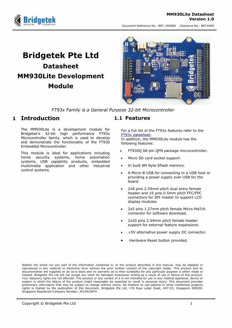
The MM930Lite is a development module for Bridgetek’s 32-bit high performance FT93x Microcontroller family, which is used to develop and demonstrate the functionality of the FT930 Embedded Microcontroller.
This module is ideal for applications including home security systems, home automation systems, USB capability products, embedded multimedia application and other industrial control systems.
1.1 Features
For a full list of the FT93x features refer to the FT93x datasheet. In addition, the MM930Lite module has the following features:
FT930Q 68-pin QFN package microcontroller.
Micro SD card socket support.
In built 8M Byte Eflash memory.
A Micro-B USB for connecting to a USB host or
providing a power supply over USB for the board.
2x8 pins 2.54mm pitch dual entry female
header and 16 pins 0.5mm pitch FFC/FPC connectors for SPI master to support LCD display modules.
2x5 pins 1.27mm pitch female Micro-MaTch
connector for software download.
2x20 pins 2.54mm pitch female header
support for external feature expansions.
+5V alternative power supply DC connector.
Hardware Reset button provided.

Copyright © Bridgetek Limited 2
MM930Lite Datasheet
Version 1.0
Document Reference No.: BRT_000085 Clearance No.: BRT#069
2 Ordering Information
Part No. Description
MM930Lite FT930 module, a FT32, 32-bit microcontroller with 128kB flash memory, 32kB data RAM and 128kB program memory embedded. SD3.0, USB2.0 Device, 8MB Eflash, several interface pin headers and connectors included.
Table 2-1 – Ordering information
3 Program Support
Example applications are provided for the MM930Lite module by Bridgetek.
The following documents provide further details for software development.
Other relevant documents and examples exist so please see the Bridgetek website for further information.
Refer to BRT_AN_010_FT93x_User_Manual for system register information.

Copyright © Bridgetek Limited 3
MM930Lite Datasheet
Version 1.0
Document Reference No.: BRT_000085 Clearance No.: BRT#069
Table of Contents
1 Introduction .................................................................... 1
1.1 Features .................................................................................... 1
2 Ordering Information ...................................................... 2
3 Program Support ............................................................. 2
4 Board Layout ................................................................... 4
4.1 Power Supply ............................................................................ 5
4.2 Microcontroller .......................................................................... 6
4.3 Micro SD Connector ................................................................... 7
4.4 USB Connector .......................................................................... 8
4.5 Programmer Interface .............................................................. 9
4.5.1 CN5 – 10-pin Micro-Match Program Interface Signals ..................................... 9
4.6 SPI Master Interface ............................................................... 11
4.6.1 J1 – 16-pin Dual Entry Header, SPI Master and Control Signals ..................... 12
4.6.2 CN4 – 16-pin FPC/FFC connector ............................................................... 13
4.7 External I/O Bus ..................................................................... 14
4.7.1 CN1 – 40-pin Dual Entry Header, Multiple function GPIO & Control Signals ..... 14
5 Board Schematic ........................................................... 16
6 Mechanical Dimensions ................................................. 18
6.1 MM930Lite PCB Dimensions .................................................... 18
7 Contact Information ...................................................... 19
Appendix A - References .................................................... 20
Document References ..................................................................... 20
Acronyms and Abbreviations ........................................................... 20
Appendix B - List of Figures and Tables ............................. 21
List of Figures ................................................................................. 21
List of Tables ................................................................................... 21
Appendix C – Revision History ........................................... 22

Copyright © Bridgetek Limited 4
MM930Lite Datasheet
Version 1.0
Document Reference No.: BRT_000085 Clearance No.: BRT#069
4 Board Layout
The MM930Lite development board is a 55 mm x 85 mm (Not including the 4 mounting holes) four-layer
printed circuit board. The layout is as shown in Figure 4-1.
Figure 4-1 – MM930Lite Board Layout
Key Features:
1. Micro SD card socket 2. Micro-MaTch connector 3. Dual-entry female header 4. FPC/FFC connector (located beneath board)
5. Alternative power supply jumper 6. +5V DC power socket
7. USB Micro-B connector 8. H/W Reset button 9. FT930Q QFN68 Microcontroller 10. External I/O bus female pin header
11. LDO regulator 12. 8M Byte Eflash memory
4
3
2
11 12 1
10
5 6 7 8 9

Copyright © Bridgetek Pte Ltd 5
MM930Lite Datasheet
Version 1.0
Document Reference No.: BRT_000085 Clearance No.: BRT#069
4.1 Power Supply
The MM930Lite development board provides optional power supply sources with JP1 jumper:
1. +5V DC power supply, CN6 right angle connector.
2. Over USB via the Micro-B USB CN3 port.
Pin No. Name
1-2 USB VBUS power supply
2-3 +5V DC power supply
Table 4-1 – JP1 Pinout
A red LED (LED1) will illuminate after the +5V power supply is applied. This supply will also drive a fixed +3.3V LDO regulator which will provide power to all peripherals of the FT930 microcontroller.
Figure 4-2– Power supply
Power supply
+3.3V LDO Power Jumper
Power
Jack
Micro
USB
port

Copyright © Bridgetek Pte Ltd 6
MM930Lite Datasheet
Version 1.0
Document Reference No.: BRT_000085 Clearance No.: BRT#069
4.2 Microcontroller
The FT930Q 68-pin QFN microcontroller (U1) provided on the board belongs to the 32-bit FT93x Microcontroller family from Bridgetek. For details of the FT930 Microcontroller, refer to the FT93x
datasheet.
Figure 4-3– FT930 Microcontroller
There are two crystals used on the MM930Lite development board. The 12MHz crystal (Y1) is the primary system clock frequency supplying the FT930Q IC. The 32.768 KHz crystal (Y2) is the system clock frequency supporting the internal RTC.
The FT930Q IC on this board is operated with a single supply of +3.3V. The FT9xx Core +1.2V from internal regulator is used as power source for internal RTC. These power output pins have decoupling capacitors as specified in the datasheet.

Copyright © Bridgetek Pte Ltd 7
MM930Lite Datasheet
Version 1.0
Document Reference No.: BRT_000085 Clearance No.: BRT#069
4.3 Micro SD Connector
The FT930Q Microcontroller has a SD3.0 controller to support different speed classes, physical sizes and capacities of Secure Digital (SD) cards. There is a Micro SD connector on the MM930Lite development
module for inserting Micro SD cards (11 x15 x1.0 mm).
There are three standard capacity cards supported:
Secure Digital (SD) standard – Up to 2GB SD memory card Secure Digital High Capacity (SDHC) standard – Over 2GB-32GB SDHC memory card Secure Digital eXtended Capacity (SDXC) standard – Over 32GB-2TB SDXC memory card
Standard class speeds 2, 4, 6, 10, and Ultra High Speed (UHS) classes U1 and U3 are all supported. The
design of the physical interface supports 4-bit SD bus mode and card detection.
Figure 4-4– Micro SD Connector

Copyright © Bridgetek Pte Ltd 8
MM930Lite Datasheet
Version 1.0
Document Reference No.: BRT_000085 Clearance No.: BRT#069
4.4 USB Connector
There is a USB connector provided on the MM930Lite board. CN3 is a Micro-B type USB2.0 connector which is used for connecting the module to a USB host.
Figure 4-5– USB Connectors

Copyright © Bridgetek Pte Ltd 9
MM930Lite Datasheet
Version 1.0
Document Reference No.: BRT_000085 Clearance No.: BRT#069
4.5 Programmer Interface
The programmer interface CN5, 2x5 pins 1.27mm pitch female Micro-Match header supports software application download, GDB debugging on the MM930Lite development board with the UMFTPD2A module..
4.5.1 CN5 – 10-pin Micro-Match Program Interface Signals
Pin No. Name Type Description
1~6 - - -
7 GND P Ground
8 DEBUG I/O FT90x One-Wire Interface
9 GDB_5V P External 5V power supply
10 RESETn P H/W Reset, active low
Table 4-2 – CN5 Pinout

Copyright © Bridgetek Pte Ltd 10
MM930Lite Datasheet
Version 1.0
Document Reference No.: BRT_000085 Clearance No.: BRT#069
Figure 4-6 – Programmer Interface

Copyright © Bridgetek Pte Ltd 11
MM930Lite Datasheet
Version 1.0
Document Reference No.: BRT_000085 Clearance No.: BRT#069
4.6 SPI Master Interface
The FT930Q microcontroller has a SPI master interface that supports single, dual and quad SPI data transfer modes. There are two alternative connectors for supporting different LCD display modules as SPI
slave devices.
The J1 dual-entry 2x8 pins 2.54mm pitch, female header (located on top of boardError! Reference source not found.) is designed for FT80x and FT81x Embedded Video Engine (EVE) family LCD display modules. As an example the ME810A-HV35R module, can connect directly to the MM930Lite development board on the bottom side with a male pin header.
The CN4 16 pins 0.5mm pitch, bottom contact FFC/FPC connector (located beneath boardError!
Reference source not found.) provides an alternative connection for LCD display modules that meet FT80x or FT81X chip technical specifications and use a 16-pin 0.5mm pitch flexible flat cable to link to the board.
Figure 4-7– SPI Master Interface

Copyright © Bridgetek Pte Ltd 12
MM930Lite Datasheet
Version 1.0
Document Reference No.: BRT_000085 Clearance No.: BRT#069
4.6.1 J1 – 16-pin Dual Entry Header, SPI Master and Control Signals
Pin No. Name Type Description
1 SPIM_SCK O SPI Master clock output
2 SPIM_SSn0 O SPI Master chip select 0, active low
3 SPIM_MISO I/O SPI Master input, Slave output
Data 1 for Quad SPI
4 SPIM_MOSI I/O SPI Master output, Slave input
Data 0 for Quad SPI
5 SPIM_IO3 I/O General I/O, data 3 for Quad SPI
6 SPIM_IO2 I/O General I/O, data 2 for Quad SPI
7 DCX O
Data / command selection pin for LCD controller
Low: Command
High: Parameter
8 CS1# O SPI Master chip select 1, active low for LCD
controller
9 VCCIO_3V3 P +3.3V power supply
10 VDD_5V P +5V power supply
11 GND P Ground
12 GND P Ground
13 PWD# O FT80X power down control, active low
14 INT# I Interrupt input from FT80X, active low
15 AUD_LIN I Audio PWM input from FT80X
16 DISP O LCD display enable
Table 4-3 – J1 Pinout

Copyright © Bridgetek Pte Ltd 13
MM930Lite Datasheet
Version 1.0
Document Reference No.: BRT_000085 Clearance No.: BRT#069
4.6.2 CN4 – 16-pin FPC/FFC connector
Pin No. Name Type Description
1,2 VCCIO_3V3 P +3.3V Power supply
3 SPIM_SCK O SPI Master clock output
4 SPIM_IO3 I/O General I/O, data 3 for Quad SPI
5 SPIM_IO2 I/O General I/O, data 2 for Quad SPI
6 SPIM_MISO I/O SPI Master input, Slave output
Data 1 for Quad SPI
7 SPIM_MOSI I/O SPI Master output, Slave input
Data 0 for Quad SPI
8 SPIM_SSn0 O SPI Master chip select 0, active low
9 INT# I Interrupt input from FT80X, active low
10 PWD# O FT80X power down control, active low
11,12,14 GND P Ground
13 AUD_LIN I Audio PWM input from FT80X
15 DISP O LCD display enable
16 MODE O
Serial interface selection for FT80X
Low: SPI interface
High: I2C interface
Table 4-4 – CN4 Pinout

Copyright © Bridgetek Pte Ltd 14
MM930Lite Datasheet
Version 1.0
Document Reference No.: BRT_000085 Clearance No.: BRT#069
4.7 External I/O Bus
There are 23 multiple function GPIOs provided on CN1 2x20 pins, 2.54mm pitch female header. External feature boards may connect via UART, PWM, ADC, DAC, SPI and I2C on these IO connectors.
Table 4-5 lists all features assigned for each pin.
4.7.1 CN1 – 40-pin Dual Entry Header, Multiple function GPIO & Control Signals
Pin No. Function 1 Function 2 Function 3 Function 4
1,3,5,15,24 GND - - -
2 FT800_AUDL - - -
4 GPIO23 UART0_TXD PWM2 -
6 GPIO22 UART0_RXD PWM3 -
7 DAC1 - - -
8 GPIO24 UART0_RTS PWM1 -
9 DAC0 - - -
10 GPIO25 UART0_CTS PWM0 -
11,25,26 - - - -
12 GPIO9 PWM2 - -
13 GPIO11 PWM0 - -
14 GPIO10 PWM1 - -
16 VDD_5V - - -
17 GPIO33 SPIM_SSn3 - -
18 GPIO34 SPIM_SCK SPIS_SCK -
19 GPIO35 SPIM_MISO SPIS_MISO -
20 GPIO36 SPIM_MOSI SPIS_MOSI -
21 GPIO38 SPIM_IO3 RTC_REF -
22 GPIO37 SPIM_IO2 SPIS_SS -
23 VCCIO_3V3 - - -
27 GPIO20 UART3_RTS - -
28 GPIO21 UART3_CTS - -
29 GPIO18 UART3_RXD - -
30 GPIO19 UART3_TXD - -
31 GPIO29 UART0_RI UART1_CTS -
32 GPIO28 UART0_DCD UART1_RTS -
33 GPIO27 UART0_DSR UART1_TXD -
34 GPIO26 UART0_DTR UART1_RXD -
35 ADC2 - - -
36 ADC1 - - -

Copyright © Bridgetek Pte Ltd 15
MM930Lite Datasheet
Version 1.0
Document Reference No.: BRT_000085 Clearance No.: BRT#069
Pin No. Function 1 Function 2 Function 3 Function 4
37 ADC3 - - -
38 GPIO17 I2CM_SDA I2CS_SDA -
39 RESETn - - -
40 GPIO18 I2CM_SCL I2CS_SCL -
Table 4-5 – CN1 External I/O Bus
Figure 4-8– External I/O Bus

Copyright © Bridgetek Pte Ltd 16
MM930Lite Datasheet
Version 1.0
Document Reference No.: BRT_000085 Clearance No.: BRT#069
5 Board Schematic
Figure 5-1 – MM930Lite MCU and External I/O Bus

Copyright © Bridgetek Pte Ltd 17
MM930Lite Datasheet
Version 1.0
Document Reference No.: BRT_000085 Clearance No.: BRT#069
Figure 5-2 – MM930Lite Interfaces and Connectors

Copyright © Bridgetek Pte Ltd 18
MM930Lite Datasheet
Version 1.0
Document Reference No.: BRT_000085 Clearance No.: BRT#069
6 Mechanical Dimensions
6.1 MM930Lite PCB Dimensions
Figure 6-1 – MM930Lite PCB Dimensions

Copyright © Bridgetek Pte Ltd 19
MM930Lite Datasheet
Version 1.0
Document Reference No.: BRT_000085 Clearance No.: BRT#069
7 Contact Information
Head Quarters – Singapore Branch Office – Taipei, Taiwan
Bridgetek Pte Ltd 178 Paya Lebar Road, #07-03 Singapore 409030 Tel: +65 6547 4827 Fax: +65 6841 6071
Bridgetek Pte Ltd, Taiwan Branch 2 Floor, No. 516, Sec. 1, Nei Hu Road, Nei Hu District Taipei 114 Taiwan , R.O.C. Tel: +886 (2) 8797 5691 Fax: +886 (2) 8751 9737
E-mail (Sales) [email protected] E-mail (Sales) [email protected]
E-mail (Support) [email protected] E-mail (Support) [email protected]
Branch Office - Glasgow, United Kingdom Branch Office – Vietnam
Bridgetek Pte. Ltd. Unit 1, 2 Seaward Place, Centurion Business Park Glasgow G41 1HH United Kingdom Tel: +44 (0) 141 429 2777 Fax: +44 (0) 141 429 2758
Bridgetek VietNam Company Limited Lutaco Tower Building, 5th Floor, 173A Nguyen Van Troi, Ward 11, Phu Nhuan District, Ho Chi Minh City, Vietnam Tel : 08 38453222 Fax : 08 38455222
E-mail (Sales) [email protected] E-mail (Sales) [email protected]
E-mail (Support) [email protected] E-mail (Support) [email protected]
Web Site
http://brtchip.com/
Distributor and Sales Representatives
Please visit the Sales Network page of the Bridgetek Web site for the contact details of our distributor(s) and sales representative(s) in your country.
System and equipment manufacturers and designers are responsible to ensure that their systems, and any Bridgetek Pte Ltd (BRT
Chip) devices incorporated in their systems, meet all applicable safety, regulatory and system-level performance requirements. All
application-related information in this document (including application descriptions, suggested Bridgetek devices and other materials) is
provided for reference only. While Bridgetek has taken care to assure it is accurate, this information is subject to customer confirmation, and Bridgetek disclaims all liability for system designs and for any applications assistance provided by Bridgetek. Use of
Bridgetek devices in life support and/or safety applications is entirely at the user’s risk, and the user agrees to defend, indemnify and
hold harmless Bridgetek from any and all damages, claims, suits or expense resulting from such use. This document is subject to
change without notice. No freedom to use patents or other intellectual property rights is implied by the publication of this document.
Neither the whole nor any part of the information contained in, or the product described in this document, may be adapted or
reproduced in any material or electronic form without the prior written consent of the copyright holder. Bridgetek Pte Ltd, 178 Paya
Lebar Road, #07-03, Singapore 409030. Singapore Registered Company Number: 201542387H.

Copyright © Bridgetek Pte Ltd 20
MM930Lite Datasheet
Version 1.0
Document Reference No.: BRT_000085 Clearance No.: BRT#069
Appendix A - References
Document References
FT93X webpage: http://brtchip.com/product/
FT93x datasheet: FT930/FT931/FT932/FT933 Datasheet
BRT_AN_010_FT93x_User_Manual
UMFTPD2A program module datasheet: DS_UMFTPD2A
ME810A-HV35R LCD display module document: DS_ME810A_HV35R
Acronyms and Abbreviations
Terms Description
USB Universal Serial Bus
QFN Quad-Flat No-leads
FFC/FPC Flexible Flat Cable/Flexible Printed Circuit
LCD Liquid Crystal Display
DC Direct Current
RAM Random Access Memory
SD Secure Digital
H/W Hardware
LDO Low Drop-Out
LED Light-Emitting Diode
RTC Real-Time Clock
I/O Input/Output
I2C Inter-Integrated Circuit
SPI Serial Peripheral Interface
UART Universal Asynchronous Receiver/Transmitter
PWM Pulse Width Modulation
ADC Analog-to-Digital Converter
DAC Digital-to-Analog Converter

Copyright © Bridgetek Pte Ltd 21
MM930Lite Datasheet
Version 1.0
Document Reference No.: BRT_000085 Clearance No.: BRT#069
Appendix B - List of Figures and Tables
List of Figures
Figure 4-1 – MM930Lite Board Layout ............................................................................................. 4
Figure 4-2– Power supply .............................................................................................................. 5
Figure 4-3– FT930 Microcontroller ................................................................................................... 6
Figure 4-4– Micro SD Connector ..................................................................................................... 7
Figure 4-5– USB Connectors .......................................................................................................... 8
Figure 4-6 – Programmer Interface ............................................................................................... 10
Figure 4-7– SPI Master Interface .................................................................................................. 11
Figure 4-8– External I/O Bus ........................................................................................................ 15
Figure 5-1 – MM930Lite MCU and External I/O Bus ......................................................................... 16
Figure 6-1 – MM930Lite PCB Dimensions ....................................................................................... 18
List of Tables
Table 2-1 – Ordering information .................................................................................................... 2
Table 4-1 – JP1 Pinout ................................................................................................................... 5
Table 4-2 – CN5 Pinout.................................................................................................................. 9
Table 4-3 – J1 Pinout .................................................................................................................. 12
Table 4-4 – CN4 Pinout................................................................................................................ 13
Table 4-5 – CN1 External I/O Bus ................................................................................................. 15

Copyright © Bridgetek Pte Ltd 22
MM930Lite Datasheet
Version 1.0
Document Reference No.: BRT_000085 Clearance No.: BRT#069
Appendix C – Revision History
Document Title: MM930Lite Datasheet
Document Reference No.: BRT_000085
Clearance No.: BRT#069
Product Page: http://brtchip.com/product/
Document Feedback: Send Feedback
Revision Changes Date
Version 1.0 Initial Release 2017-06-08
Related Documents