STRENGTH IN PEOPLE: STRENGTH IN CONCRETE CF-AB - Technical Information/2004 BRIDGES

Bridges
Dec 02, 2015
bridges design
Welcome message from author
This document is posted to help you gain knowledge. Please leave a comment to let me know what you think about it! Share it to your friends and learn new things together.
Transcript

S T R E N G T H I N P E O P L E :S T R E N G T H I N C O N C R E T E
C F - A B - Te c h n i c a l I n f o r m a t i o n / 2 0 0 4
B R I D G E S

TRAPEZOID GIRDER
TRAPEZOID GIRDERS 2.1
SECTION II -
INDEX
SECTION III -
SECTION IV -
NU GIRDERS
TRAPEZOIDAL GIRDERS
I- GIRDERS
BOX GIRDERS
INDEX i
SECTION I -


TRAPEZOID GIRDER
TRAPEZOID GIRDERS 2.1
INTRODUCTION
INTRODUCTION ii
The contents of this technical information handbook have been preparedby Con-Force Structures Limited to assist designers and thoseresponsible for the bridge stock of Western Canada.
As the prime manufacturer of pre-cast concrete bridge beams in theWestern provinces, Con-Force has recognized its responsibility to assistprofessionals by providing data for readily available sections togetherwith simple load/span charts to help speedy evaluation of proposedsection sizes.
Con-Force introduced the N.U. Girder to Canada in 1999 and hasassisted to progress the development of girders up to 2800 deep and todate, a length of 64.5 m. The problems associated with handling, storage,transportation and erection of deep slender girders have been resolvedby the Con-Force in-house Engineering/Erection departments.Information relating to temporary stiffining associated with long girderscan be provided upon request.
The data presented is based upon Con-Force’s understanding of therequirements of the various codes and standards which have beenreferenced in the text. Con-Force can not be responsible for differinginterpretation used by others.
INTRODUCTION


NU GIRDERS

NU GIRDER
NU GIRDERS 1.1
SPAN CAPABILITY
Designers have experienced limitations when using traditional existing precast,prestressed concrete I-girders. Existing sections were not well proportioned totake advantage of high strength concrete and 0.6” strand.
To take advantage of advances in precast concrete technology, Con-Force hasrecently introduced the NU girder. The girder has been already used on a numberof projects.
The NU girder has a wide bottom flange to enhance the compressive strength innegative moment regions for continuous span designs, and to allow placementof a large number of strands in the bottom flange for simple span designs.
The relatively long span capability and shallow depth of the NU girder makes itan economical alternative in situations previously reserved for structural steelgirder systems.
The high level of prestressing will normally require the use of high strengthconcrete. The span capability diagrams were developed using a 28-day concretestrength of f‘c = 65 MPa. The unit weight of concrete was assumed to be 2400kg/m3. The concrete may contain silica fume with air entrainment of 5 to 7%.The modulus of elasticity of concrete was calculated using the formula:
( ) 5.1'
230069003000
+= c
cc fEγ
The minimum release strength assumed was 42 MPa. Where there are twodashed lines in the charts, they represent limits for 42 MPa and 47 MPa releasestrength. Any point on a chart above the 42 MPa line indicates a situation wherethe release strength has to be higher than 42 MPa due to handling stresslimitations. This situation would require special mix designs which may increasethe cost.
The concrete deck 28-day strength was assumed to be 35 MPa.
Concrete
MATERIALPROPERTIES
INTRODUCTION

NU GIRDER
1.2 CON-FORCE STRUCTURES LIMITED
The prestressing strand is 15 mm in diameter,uncoated, seven-wire, low relaxation strand,meeting the requirements of CSA Standard G279,Grade 1860, with an area of 140 mm2. The initialjacking force is
kNfA pup 182%70 = .
The adjacent table lists the height above the soffit,at midspan, of the total prestressing force, forthe different number of strands in the bottomflange that were used in the calculations. The2800 mm deep girder uses up to an additional 8– 15 mm strands in the top flange to control thelateral stability of the girder at handling andtransportation.
End stresses were not checked for all spanconditions indicated in the charts . Stresses maybe controlled by debonding and/or deflectingselected strands at the end of the girders.
NU girders may be post-tensioned to formcontinuous beams. Reference should be madeto CAN/CSA-S6-00. When post -tensioning isincluded, a web width of 185 mm shall be used. For long span post-tensionedbridges, oiled strand (using approved corrosion inhibiting oil) may lead to decreasedfriction coefficients. Con-Force has experience constructing bridge beams withoiled post-tensioning strand.
The span capability charts were developed in accordance with the CAN/CSA-S6-00 Canadian Highway Bridge Design Code. Simple spans were assumed for allloads. The calculations were done for interior girders.
A CL 800 truck load was used, including a 25% dynamic load allowance.
A uniformly distributed load of 9 kN/m, that is 3.0 m wide was used as a lane load,superimposed with a CL 800 truck, with each axle reduced to 80%.
Yp[mm]
16 60
20 65
24 73
28 78
32 82
36 85
40 93
44 99
48 106
52 116
56 131
60 152
64 176
68 203
SPAN CAPABILITY
NumberOf Strands
PrestressingStrand
Post-Tensioning
DESIGNCRITERIA
Truck Load
Lane Load

NU GIRDER
NU GIRDERS 1.3
Dead loads considered to act on the untopped section are:
• girder self weight,
• 75 mm thick haunch
• 225 mm thick deck
• cross bracing (0.5 kN/m per girder)
Dead loads considered to act on the topped section are:
• 90 mm thick asphalt,• railing and curbs (13 kN/m total load per bridge)
A lane width of 3.3 m was used in the calculations.
The width of the bridge was calculated as:
(number of lanes x lane width) + 2 x 0.5 m
The multi-lane reduction factor was used. (CAN/CSA-S6-00, Clause 3.8.4.2)
The following average values of prestress losses were assumed:
• Initial Losses = 8 %
• Final Losses = 20 %
Tension stresses at the bottom of the section at midspan are limited to cf ′4.0 .
Compressive stress is not limited at service, although the ratio pdc
is limited
to 5.0 .
Tension stresses are limited to crif5.0 (CAN/CSA-S6-00, Clause 8.8.4.6).
Compressive stresses are limited to cif ′6.0 .
SPAN CAPABILITY
Lanes
Prestress Losses
AllowableStresses (Service)
AllowableStresses (atRelease andHandling)
Dead Loads
Superimosed
Dead Loads

NU GIRDER
1.4 CON-FORCE STRUCTURES LIMITED
GIRDER DIMENSIONS & SECTION PROPERTIES
2800 x 160 *
SPAN CAPABILITY DIAGRAM **
32
36
40
44
48
52
56
60
64
68
35 40 45 50 55 60 65
Simple Span [m]
Num
ber o
f 15
mm
Dia
m. S
tran
ds
Girder Spacing [m] 3.5 3.0 2.5 2.0 1.5
1.235f`ci*** = 42 MPa
NOTES: * (Girder depth) x (Web width) ** Based on 0.4 (f'c)1/2 allowable tension at midspan. *** Concrete release strength.

NU GIRDER
NU GIRDERS 1.5
GIRDER DIMENSIONS & SECTION PROPERTIES
2800 x 185 *
SPAN CAPABILITY DIAGRAM **
32
36
40
44
48
52
56
60
64
68
35 40 45 50 55 60 65
Simple Span [m]
Num
ber o
f 15
mm
Dia
m. S
tran
ds
Girder Spacing [m] 3.5 3.0 2.5 2.0 1.5 1.26
NOTES: * (Girder depth) x (Web width) ** Based on 0.4 (f'c)1/2 allowable tension at midspan.
NU GIRDER
1.6 CON-FORCE STRUCTURES LIMITED
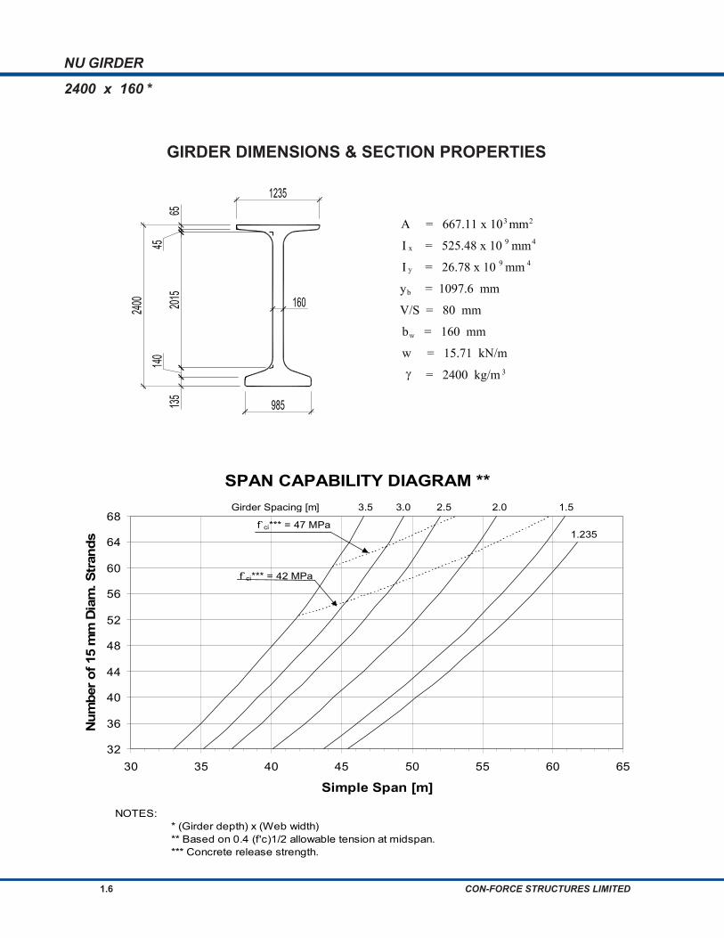
GIRDER DIMENSIONS & SECTION PROPERTIES
2400 x 160 *
SPAN CAPABILITY DIAGRAM **
32
36
40
44
48
52
56
60
64
68
30 35 40 45 50 55 60 65
Simple Span [m]
Num
ber o
f 15
mm
Dia
m. S
tran
ds
Girder Spacing [m] 3.5 3.0 2.5 2.0 1.5
1.235
f`ci*** = 42 MPa
f`ci*** = 47 MPa
NOTES: * (Girder depth) x (Web width) ** Based on 0.4 (f'c)1/2 allowable tension at midspan. *** Concrete release strength.

NU GIRDER
NU GIRDERS 1.7
GIRDER DIMENSIONS & SECTION PROPERTIES
2400 x 185 *
SPAN CAPABILITY DIAGRAM **
32
36
40
44
48
52
56
60
64
68
30 35 40 45 50 55 60 65
Simple Span [m]
Num
ber o
f 15
mm
Dia
m. S
tran
ds
Girder Spacing [m] 3.5 3.0 2.5 2.0 1.5 1.26
f`ci*** = 42 MPa
f`ci*** = 47 MPa
NOTES: * (Girder depth) x (Web width) ** Based on 0.4 (f'c)1/2 allowable tension at midspan. *** Concrete release strength.

NU GIRDER
1.8 CON-FORCE STRUCTURES LIMITED
GIRDER DIMENSIONS & SECTION PROPERTIES
2000 x 160 *
SPAN CAPABILITY DIAGRAM **
28
32
36
40
44
48
52
56
60
64
25 30 35 40 45 50 55 60
Simple Span [m]
Num
ber o
f 15
mm
Dia
m. S
tran
ds
Girder Spacing [m] 3.5 3.0 2.5 2.0 1.5
1.235
f`ci*** = 42 MPa
f`ci*** = 47 MPa
NOTES: * (Girder depth) x (Web width) ** Based on 0.4 (f'c)1/2 allowable tension at midspan. *** Concrete release strength.

NU GIRDER
NU GIRDERS 1.9
GIRDER DIMENSIONS & SECTION PROPERTIES
2000 x 185 *
SPAN CAPABILITY DIAGRAM **
28
32
36
40
44
48
52
56
60
64
25 30 35 40 45 50 55 60
Simple Span [m]
Num
ber o
f 15
mm
Dia
m. S
tran
ds
Girder Spacing [m] 3.5 3.0 2.5 2.0 1.5 1.26
f`ci*** = 42 MPa
f`ci*** = 47 MPa
NOTES: * (Girder depth) x (Web width) ** Based on 0.4 (f'c)1/2 allowable tension at midspan. *** Concrete release strength.

NU GIRDER
1.10 CON-FORCE STRUCTURES LIMITED
GIRDER DIMENSIONS & SECTION PROPERTIES
1600 x 160 *
SPAN CAPABILITY DIAGRAM **
20
24
28
32
36
40
44
48
52
56
20 25 30 35 40 45 50
Simple Span [m]
Num
ber o
f 15
mm
Dia
m. S
tran
ds
Girder Spacing [m] 3.5 3.0 2.5 2.0 1.5 1.235
f`ci*** = 42 MPa
f`ci*** = 47 MPa
NOTES: * (Girder depth) x (Web width) ** Based on 0.4 (f'c)1/2 allowable tension at midspan. *** Concrete release strength.

NU GIRDER
NU GIRDERS 1.11
GIRDER DIMENSIONS & SECTION PROPERTIES
1600 x 185 *
SPAN CAPABILITY DIAGRAM **
20
24
28
32
36
40
44
48
52
56
20 25 30 35 40 45 50
Simple Span [m]
Num
ber o
f 15
mm
Dia
m. S
tran
ds
Girder Spacing [m] 3.5 3.0 2.5 2.0 1.5 1.26
f`ci*** = 42 MPa
f`ci*** = 47 MPa
NOTES: * (Girder depth) x (Web width) ** Based on 0.4 (f'c)1/2 allowable tension at midspan. *** Concrete release strength.

NU GIRDER
1.12 CON-FORCE STRUCTURES LIMITED
GIRDER DIMENSIONS & SECTION PROPERTIES
1200 x 160 *
SPAN CAPABILITY DIAGRAM **
16
20
24
28
32
36
40
44
48
52
15 20 25 30 35 40
Simple Span [m]
Num
ber o
f 15
mm
Dia
m. S
tran
ds
Girder Spacing [m] 3.5 3.0 2.5 2.0 1.5 1.235
f`ci*** = 42 MPa
f`ci*** = 47 MPa
NOTES: * (Girder depth) x (Web width) ** Based on 0.4 (f'c)1/2 allowable tension at midspan. *** Concrete release strength.

NU GIRDER
NU GIRDERS 1.13
GIRDER DIMENSIONS & SECTION PROPERTIES
1200 x 185 *
SPAN CAPABILITY DIAGRAM **
16
20
24
28
32
36
40
44
48
52
15 20 25 30 35 40
Simple Span [m]
Num
ber o
f 15
mm
Dia
m. S
tran
ds
Girder Spacing [m] 3.5 3.0 2.5 2.0 1.5 1.26
f`ci*** = 42 MPa
f`ci*** = 47 MPa
NOTES: * (Girder depth) x (Web width) ** Based on 0.4 (f'c)1/2 allowable tension at midspan. *** Concrete release strength.

NU GIRDER
1.14 CON-FORCE STRUCTURES LIMITED
STRAND DETAIL
NU GIRDER END REINFORCING WITH DEFLECTED STRAND
NU GIRDER
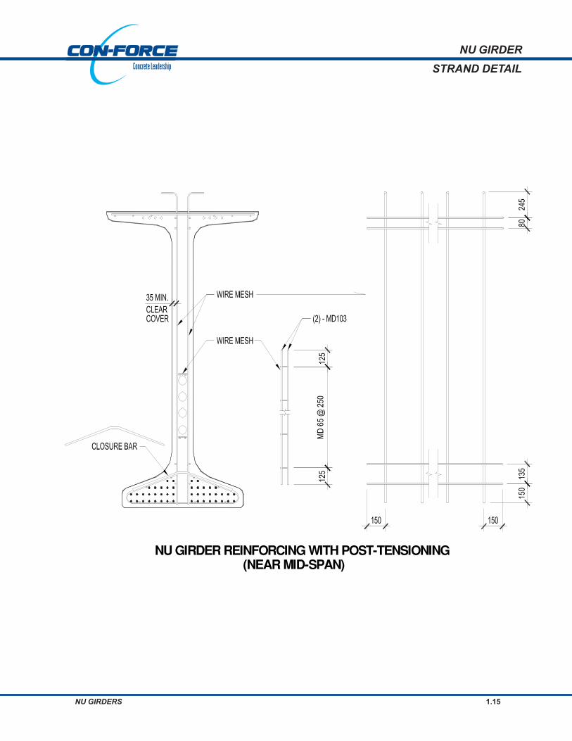
NU GIRDERS 1.15
STRAND DETAIL
NU GIRDER REINFORCING WITH POST−TENSIONING(NEAR MID−SPAN)

NU GIRDER
1.16 CON-FORCE STRUCTURES LIMITED
STRAND DETAIL

NU GIRDER
NU GIRDERS 1.17
BRACING DETAIL
STEEL BRACING (DIAPHRAGM)CONNECTION TO TOP FLANGE
OF NU GIRDER
STEEL BRACING (DIAPHRAGM)CONNECTION TO BOTTOM FLANGE
OF NU GIRDER

NU GIRDER
1.18 CON-FORCE STRUCTURES LIMITED
BEARING DETAIL
BEARING DETAIL 1 (FIXED BEARING)

NU GIRDER
NU GIRDERS 1.19
BEARING DETAIL
BEARING DETAIL 2 (SLIDING BEARING)

NU GIRDER
1.20 CON-FORCE STRUCTURES LIMITED
BEARING DETAIL
BEARING DETAIL 3 (NARROW JOINT)

GIRDERSTRAPEZOIDAL

TRAPEZOID GIRDER
TRAPEZOID GIRDERS 2.1
DESIGN
The span capability diagrams were developed using a 28-day minimum concretestrength of f‘c = 65 MPa.
The unit weight of concrete was assumed to be 2400 kg/m3. The concrete may containsilica fume with air entrainment of 5 to 7%. The modulus of elasticity of concrete wascalculated using the formula:
( ) 5.1'
230069003000
+= ccc fE γ
The minimum concrete release strength was assumed to be 42 MPa.
The concrete deck minimum 28-day strength was assumed to be 35 MPa.
The prestressing strand is 15 mm in diameter, uncoated, seven-wire, low relaxationstrand, meeting the requirements of CSA Standard G279, Grade 1860, with an area
of 140 mm2. The initial jacking force is kNfA pup 182%70 = .
The height of the prestressing force centre above soffit was assumed to be 85 mm.
End stresses were not checked for all span conditions. They may be controlled bydebonding selected strands at the ends of the girders.
The span capability charts were developed in accordance with the CAN/CSA-S6-00Canadian Highway Bridge Design Code. Simple spans were assumed for all loads.The calculations were done for interior girders.
A CL 800 truck load was used, including a 25% dynamic load allowance.
A uniformly distributed load of 9 kN/m, that is 3.0 m wide was used as a lane load,superimposed with a CL 800 truck, with each axle reduced to 80%.
PrestressingStrand
DESIGNCRITERIA
Truck Load
Lane Load
Concrete
MATERIALPROPERTIES

TRAPEZOID GIRDER
2.2 CON-FORCE STRUCTURES LIMITED
DESIGN
Lanes
Prestress Losses
Allowable Stresses(Service)
Allowable Stresses(at Release andHandling)
Dead Loads Dead loads considered to act on the untopped section included:
• girder self weight,
• 75 mm thick haunch,
• 225 mm thick deck,
• cross bracing (0.5 kN/m per girder).
Dead loads considered to act on the topped section included:
• 90 mm thick asphalt,
• railing and curbs (13 kN/m total load per bridge),
A lane width of 3.3 m was used in the calculations.
The width of the bridge was calculated as:
(number of lanes x lane width) + 2 x 0.5 m
The multi lane reduction factor was used. (CAN/CSA-S6-00, Clause 3.8.4.2)
The following average prestress losses were assumed:
• Initial losses = 8 %
• Final Losses = 20 %
Tension stresses at the bottom of the section at midspan are limited to cf ′4.0 .
Compressive stress is not limited at service, although the ratio c/dp is limited to0.5.
Tension stresses are limited to 0.5 fcri (CAN/CSA-A6-00, Clause 8.8.4.6).
Compressive stresses are limited to cif ′6.0 .
SuperimposedDead Loads

TRAPEZOID GIRDER
TRAPEZOID GIRDERS 2.3
w = 24.78 kN/m
2
x
V/S = 91 mm
y = 797 mmb
4I = 370.6 x 10 mm9
3A = 1052.6 x 10 mm
3γ = 2400 kg/m
SPAN CAPABILITY DIAGRAM **
20
24
28
32
36
40
44
48
52
56
17.5 20 22.5 25 27.5 30 32.5
Simple Span [m]
Num
ber o
f 15
mm
Dia
m. S
tran
ds
Girder Spacing [m] 6.5 6.0 5.5 5.0 4.5 4 0
NOTES: * Trapezoid Girder Depth ** Based on 0.4 (f'c)1/2 allowable tension at midspan.
GIRDER DIMENSIONS & SECTION PROPERTIES
1650 *

TRAPEZOID GIRDER
2.4 CON-FORCE STRUCTURES LIMITED
w = 26.85 kN/m
2
x
V/S = 95 mm
y = 888 mmb
4I = 474.9 x 10 mm9
3A = 1140.4 x 10 mm
3γ = 2400 kg/m
SPAN CAPABILITY DIAGRAM **
20
24
28
32
36
40
44
48
52
56
17.5 20 22.5 25 27.5 30 32.5 35
Simple Span [m]
Num
ber o
f 15
mm
Dia
m. S
tran
ds
Girder Spacing [m] 6.5 6.0 5.5 5.0 4.5 4.0
NOTE: *Trapezoid Girder Depth ** Based on 0.4 (f'c)1/2 allowable tension at midspan.
GIRDER DIMENSIONS & SECTION PROPERTIES
1800 *

TRAPEZOID GIRDER
TRAPEZOID GIRDERS 2.5
w = 29.54 kN/m
2
x
V/S = 98 mm
y = 1003 mmb
4I = 631.0 x 10 mm9
3A = 1254.6 x 10 m m
3γ = 2400 kg/m
SPAN CAPABILITY DIAGRAM **
20
24
28
32
36
40
44
48
52
56
20 22.5 25 27.5 30 32.5 35
Simple Span [m]
Num
ber o
f 15
mm
Dia
m. S
tran
ds
Girder Spacing [m] 6.5 6.0 5.5 5.0 4.5 4.0
NOTE: * Trapezoid Girder Depth ** Based on 0.4 (f'c)1/2 allowable tension at midspan.
GIRDER DIMENSIONS & SECTION PROPERTIES
2000 *

TRAPEZOID GIRDER
2.6 CON-FORCE STRUCTURES LIMITED
w = 32.12 kN/m
2
x
V/S = 102 mm
y = 1122 mmb
4I = 819.3 x 10 mm9
3A = 1364.2 x 10 mm
3γ = 2400 kg/m
SPAN CAPABILITY DIAGRAM **
20
24
28
32
36
40
44
48
52
56
20 22.5 25 27.5 30 32.5 35 37.5
Simple Span [m]
Num
ber o
f 15
mm
Dia
m. S
tran
ds
Girder Spacing [m] 6.5 6.0 5.5 5.0 4.5 4.0
NOTE: * Trapezoid Girder Depth ** Based on 0.4 (f'c)1/2 allowable tension at midspan.
GIRDER DIMENSIONS & SECTION PROPERTIES
2200 *
TRAPEZOID GIRDER
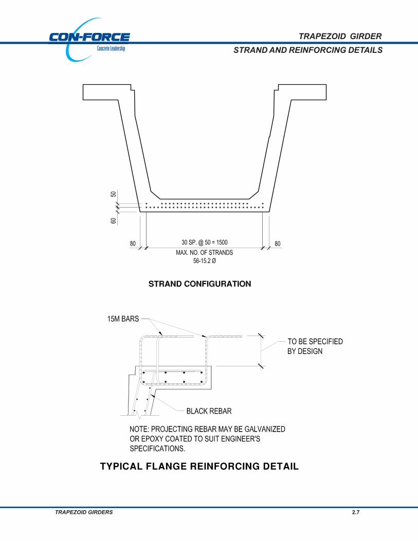
TRAPEZOID GIRDERS 2.7
STRAND AND REINFORCING DETAILS
TYPICAL FLANGE REINFORCING DETAIL

TRAPEZOID GIRDER
2.8 CON-FORCE STRUCTURES LIMITED
CONNECTION DETAIL

GIRDERSI -

I-GIRDER SPAN CAPABILITY DIAGRAMS 3.1
I-GIRDERSPAN CAPABILITY DIAGRAMS
The high level of prestressing will normally require the use of high strength concrete.The span capability diagrams were developed using a 28-day minimum concretestrength of f‘c = 65 MPa.
The unit weight of concrete was assumed to be 2400 kg/m3. The modulus ofelasticity of concrete was calculated using the formula:
( ) 5.1'
230069003000
+= ccc fE γ
The deck 28-day minimum strength was assumed to be 35 MPa.
The prestressing strand is 13 mm in diameter, uncoated, seven-wire, low relaxationstrand, meeting the requirements of CSA Standard G279, Grade 1860, with an
area of 99 mm2. The initial jacking force is kNfA pup 129%70 = .
The table on the following page lists the height above the soffit, at midspan, of thetotal prestressing force, for the different number of strands that were used in thecalculations. End stresses were not checked for all span conditions indicated inthe charts. Stresses may be controlled by debonding and/or deflecting selectedstrands at the end of the girders.
The span capability charts were developed in accordance with the CAN/CSA-S6-00 Canadian Highway Bridge Design Code. Simple spans were assumed for allloads. The calculations were done for interior girders.
A CL 800 truck load was used, including a 25% dynamic load allowance.
A uniformly distributed load of 9 kN/m, that is 3.0 m wide was used as a lane load,superimposed with a CL 800 truck, with each axle reduced to 80%.
Dead loads considered to act on the untopped section included:
• girder self weight
• 75 mm thick haunch
• 225 mm thick deck
• cross bracing (0.5 kN/m per girder)
MATERIALPROPERTIES
Concrete
Prestressing Strand
Truck Load
DESIGN
CRITERIA
Lane Load
Dead Loads

3.2 CON-FORCE STRUCTURES LIMITED
I-GIRDERSPAN CAPABILITY DIAGRAMS
Dead loads considered to act on the topped section included:
• 90 mm thick asphalt
• railing and curbs (13 kN/m total load per bridge)
A lane width of 3.3 m was used in the calculations.
The width of the bridge was calculated as:
(number of lanes x lane width) + 2 x 0.5 m
The multi-lane reduction factor was used (CAN/CSA-S6-00, Clause 3.8.4.2).
The following prestress losses were used:
• Initial losses = 8 %
• Final Losses = 20 %
Tension stresses at the bottom of the section at midspan are limited to cf ′4.0 .
Compressive stress is not limited at service, although the ratio c/dp is limited to0.5.
Tension stresses are limited to 0.5 fcri (CAN/CSA-A6-00, Clause 8.8.4.6).
Compressive stresses are limited to cif ′6.0 .
Prestress Losses
Allowable Stresses(Service)
Girder Depth [mm]
914 1118 1295 / 1473 1727 2000 2300 / 2750
# of Strands
Yp [mm]
# of Strands
Yp [mm]
# of Strands
Yp [mm]
# of Strands
Yp [mm]
# of Strands
Yp [mm]
# of Strands
Yp [mm]
6 51 8 51 10 51 14 55 24 81 32 115
9 68 12 55 14 62 18 74 28 97 36 137
12 77 16 67 18 79 22 79 32 100 40 161
15 92 20 82 22 83 26 96 36 106 44 160
18 105 24 85 26 90 30 97 40 122 48 182
21 117 28 104 30 122 34 117 44 125 52 204
32 110 34 126 38 121 48 132 56 204
42 140 52 148 60 227
46 160 56 154 64 227
50 163 60 172 68 251
Superimposed DeadLoads
Lanes
Allowable Stresses(at Release andHandling)

I-GIRDER SPAN CAPABILITY DIAGRAMS 3.3
I-GIRDER
GIRDER DIMENSIONS & SECTION PROPERTIES
2750 *
γ
A = 782.7 x 10 mm
I = 854.8 x 10 mm
I = 42.5 x 10 mmx
y = 1438 mmb
y
V/S = 84.9 mm
b = 150 mm
w = 18.43 kN/m
= 2400 kg/m
w
3
9
3
9
4
2
4
SPAN CAPABILITY DIAGRAM **
32
36
40
44
48
52
56
60
64
68
30 35 40 45 50 55
Simple Span [m]
Num
ber o
f 13
mm
Dia
m. S
tran
ds
Girder Spacing [m] 3.0 2.5 2.0 1.53.5
NOTE: * Girder Depth ** Based on 0.4 (f'c)1/2 allowable tension at midspan.

3.4 CON-FORCE STRUCTURES LIMITED
I-GIRDER
GIRDER DIMENSIONS & SECTION PROPERTIES
2300 *
γ
w = 1 5 .37 k N /m
b = 15 0 m m
V /S = 8 8 .0 m m
y = 11 1 2 m m
I = 2 1 .7 x 1 0 m m
I = 4 8 3 .9 x 1 0 m m
A = 65 2 .7 x 1 0 m m
= 2 40 0 k g /m
w
b
y
x
3
49
9
3
4
2
SPAN CAPABILITY DIAGRAM **
32
36
40
44
48
52
56
60
64
68
25 30 35 40 45 50 55
Simple Span [m]
Num
ber o
f 13
mm
Dia
m. S
tran
ds
Girder Spacing [m] 3.0 2.5 2.0 1.5 1.03.5
NOTE: * Girder Depth ** Based on 0.4 (f'c)1/2 allowable tension at midspan.

I-GIRDER SPAN CAPABILITY DIAGRAMS 3.5
I-GIRDER
GIRDER DIMENSIONS & SECTION PROPERTIES
2000 *
= 2400 kg/mγ 3
A = 528 .6 x 10 m m 3
9I = 291 .7 x 10 m m 4
by = 951 .6 m m
V /S = 82 .2 m m
b = 140 m mw
x
2
y4I = 13 .6 x 10 m m9
w = 12 .45 kN /m
SPAN CAPABILITY DIAGRAM **
24
28
32
36
40
44
48
52
56
60
20 25 30 35 40 45 50
Simple Span [m]
Num
ber o
f 13
mm
Dia
m. S
tran
ds
Girder Spacing [m] 3.0 2.5 2.0 1.5
1.0
3.5f`ci = 42 MPa***
NOTE: * Girder Depth ** Based on 0.4 (f'c)1/2 allowable tension at midspan. *** Concrete release strength.

3.6 CON-FORCE STRUCTURES LIMITED
I-GIRDER
GIRDER DIMENSIONS & SECTION PROPERTIES
1727 *
= 2 4 0 0 k g /mγ 3
A = 4 3 3 .1 x 1 0 m m 3
9I = 1 7 7 .7 x 1 0 m m 4
by = 7 9 2 .2 m m
V /S = 7 6 .6 m m
b = 1 2 7 m mw
x
2
y4I = 9 .8 x 1 0 m m9
w = 1 0 .2 0 k N /m
SPAN CAPABILITY DIAGRAM **
14
18
22
26
30
34
38
42
46
50
15 20 25 30 35 40 45
Simple Span [m]
Num
ber o
f 13
mm
Dia
m. S
tran
ds
Girder Spacing [m] 3.0 2.5 2.0 1.5 1.03.5
f`ci =42 MPa***
NOTE: * Girder Depth ** Based on 0.4 (f'c)1/2 allowable tension at midspan. *** Concrete release strength.

I-GIRDER SPAN CAPABILITY DIAGRAMS 3.7
I-GIRDER
GIRDER DIMENSIONS & SECTION PROPERTIES
1473 *
= 2 4 0 0 k g /mγ 3
A = 3 4 0 .0 x 1 0 m m 3
9I = 9 8 .6 x 1 0 m m 4
by = 6 8 6 .3 m m
V /S = 6 9 .6 m m
b = 1 2 7 m mw
x
2
y4I = 5 .7 x 1 0 m m9
w = 8 .0 1 k N /m
SPAN CAPABILITY DIAGRAM **
10
14
18
22
26
30
34
17.5 20 22.5 25 27.5 30 32.5 35
Simple Span [m]
Num
ber o
f 13
mm
Dia
m. S
tran
ds
Girder Spacing [m] 2.0 1.7 1.5 1.2 1.002.2
NOTE: * Girder Depth ** Based on 0.4 (f'c)1/2 allowable tension at midspan.

3.8 CON-FORCE STRUCTURES LIMITED
I-GIRDER
GIRDER DIMENSIONS & SECTION PROPERTIES
1295 *
= 2400 kg/mγ 3
A = 304.4 x 10 m m 3
9I = 66.0 x 10 m m 4
by = 575.2 m m
V /S = 70.3 m m
b = 127 m mw
x
2
y4I = 4.75 x 10 m m9
w = 7 .17 kN /m
SPAN CAPABILITY DIAGRAM **
10
14
18
22
26
30
34
15 17.5 20 22.5 25 27.5 30 32.5
Simple Span [m]
Num
ber o
f 13
mm
Dia
m. S
tran
ds
Girder Spacing [m] 2.0 1.7 1.5 1.2 1.00
NOTE: * Girder Depth ** Based on 0.4 (f'c)1/2 allowable tension at midspan.

I-GIRDER SPAN CAPABILITY DIAGRAMS 3.9
I-GIRDER
GIRDER DIMENSIONS & SECTION PROPERTIES
1118 *
= 2400 kg/mγ 3
A = 268.9 x 10 mm 3
9I = 41.1 x 10 mm 4
by = 467.3 mm
V/S = 71.2 mm
b = 127 mmw
x
2
y4I = 4.1 x 10 mm9
w = 6.33 kN/m
SPAN CAPABILITY DIAGRAM **
8
12
16
20
24
28
32
15 17.5 20 22.5 25 27.5 30
Simple Span [m]
Num
ber o
f 13
mm
Dia
m. S
tran
ds
Girder Spacing [m] 2.0 1.7 1.5 1.2 1.00
NOTE: * Girder Depth ** Based on 0.4 (f'c)1/2 allowable tension at midspan.

3.10 CON-FORCE STRUCTURES LIMITED
I-GIRDER
GIRDER DIMENSIONS & SECTION PROPERTIES
914 *
= 2400 kg/mγ 3
A = 198.5 x 10 mm 3
9I = 19.8 x 10 mm4
by = 396.8 mm
V/S = 63.5 mm
b = 127 mmw
x
2
y4I = 2.05 x 10 mm9
w = 4.68 kN/m
SPAN CAPABILITY DIAGRAM **
6
9
12
15
18
21
12.5 15 17.5 20 22.5 25
Simple Span [m]
Num
ber o
f 13
mm
Dia
m. S
tran
ds
Girder Spacing [m] 1.5 1.2 1.0 0.7
NOTE: * Girder Depth ** Based on 0.4 (f'c)1/2 allowable tension at midspan.

I-GIRDER SPAN CAPABILITY DIAGRAMS 3.11
I-GIRDERSTRAND DETAIL

3.12 CON-FORCE STRUCTURES LIMITED
I-GIRDERSTRAND DETAIL
GIRDERSBOX

BOX GIRDERS 4.1
DESIGN CRITERIASINGLE BOX GIRDER
MATERIALS
DESIGN • CAN/CSA – S6-M Specifications.
• LOADING (assumed for the charts)
- LIVE LOAD – CL 800
- DEAD LOAD Includes: 100 mm min. composite concrete overlay
50 mm allowance for future wearing surface
• Minimum compressive strength for girders:
28 days = 45 MPa
release = 28 MPa.
• Concrete shall be of standard weight aggregate with a maximum size of 14 mmand shall contain 6% ± 1% entrained air.
• Prestressing strand shall be 15mm φ (7 wire) uncoated low relaxation strand,1860 MPa grade.
• Reinforcing steel shall conform to CSA G30.12M grade 400W.
• Initial tensioning shall be 182 kN per 15 mm φ strand.
• Reinforcing bars shall have 35 mm minimum cover unless otherwise noted.
• Lateral post-tensioning may be provided at diaphragm locations.
• Top of boxes shall have a transverse raked finish.
• Dowel holes and shear keys shall be filled with an approved grout.
FABRICATION

4.2 CON-FORCE STRUCTURES LIMITED
SPAN CAPABILITY
PRECAST SECTION PROPERTIES AND SPAN RANGE
SECTION SELF A I x 109
Sb x 106
Yb
DEPTH WEIGHT
[kN/m]* [mm2] [mm
4] [mm
3] [mm]
900 10.86 432700 46.9 101.5 462
1100 12.12 482700 77.7 137.5 565
1300 13.37 532700 118.1 177.0 667
1300S 14.32 570400 128.6 203.9 631
* Based on a concrete density of 2500 kg/m3.
40
SPAN RANGE [m]
20 25 30 35
*Based on a concrete density of 2400 kg/m3
SINGLE BOX GIRDER

BOX GIRDERS 4.3
DESIGN CRITERIA
• CAN/CSA – S6-M Specifications
• LOADING (assumed for the charts)
- LIVE LOAD – CL 800
- DEAD LOAD Includes: 100 mm min. composite concrete overlay
50 mm allowance for future wearing surface
• Minimum compressive strength for girders:
28 days = 45 MPa
release = 28 MPa.
• Concrete shall be of standard weight aggregate with a maximum size of 14 mm,and shall contain 6%; +/- 1% entrained air.
• Prestressing strand shall be 15mm φ (7 wire) uncoated low relaxation strand,1860 MPa grade.
• Reinforcing steel shall conform to CSA G30.12M grade 400W.
• Initial tensioning shall be 182 kN per 15 mm φ strand.
• Reinforcing bars shall have 35 mm minimum cover unless otherwise noted.
• Lateral post-tensioning shall be provided at diaphragm locations.
• Top of boxes shall have a transverse raked finish.
• Dowel holes and shear keys shall be filled with an approved grout.
DOUBLE BOX GIRDER
MATERIAL
FABRICATION
DESIGN

4.4 CON-FORCE STRUCTURES LIMITED
DOUBLE BOX GIRDER
SPAN CAPABILITY
PRECAST SECTION PROPERTIES AND SPAN RANGE
SECTION SELF A I x 109
Sb x 106
Yb
DEPTH WEIGHT
[kN/m]* [mm2] [mm
4] [mm
3] [mm]
500 8.64 352035 10.4 41.0 254
600 9.42 384035 16.9 55.3 306
700 10.2 416035 25.3 70.9 357
* Based on a concrete density of 2500 kg/m3.
19
SPAN RANGE [m]
11 13 15 17
*Based on a concrete density of 2400 kg/m3

BOX GIRDERS 4.5
• CAN/CSA – S6-M Specifications.
• LOADING (assumed for the charts)
- LIVE LOAD – CL 800
- DEAD LOAD Includes 50 mm asphalt
• Minimum compressive strength for girders:
28 days = 45 MPa
release = 28 MPa.
• Concrete shall be of standard weight aggregate with a maximum size of 14mm and shall contain 6% ± 1% entrained air. Concrete may contain 5% silicafume.
• Prestressing strand shall conform to the requirements of CSA Standard G279-M, grade 1860, low relaxation.
• Reinforcing steel shall be fabricated from deformed bars conforming to therequirements of CSA Standard G30.18 400W.
• Initial tensioning shall be 182 kN per 15 mm φ strand.
• Construction procedures shall conform to “Saskatchewan Highways andTransportation Specification 7800”.
• Exterior face of exterior stringers shall be finished to a smooth and uniformcolour and texture. Other surfaces shall have all pockets filled and all finsremoved. Top shall have a broom finish.
• All voids shall be formed with Norlux Fibre-Forms or equivalent.
SASKATCHEWAN BOX GIRDER
DESIGN CRITERA
DESIGN
MATERIALS
FABRICATION

4.6 CON-FORCE STRUCTURES LIMITED
SASKATCHEWAN BOX GIRDER
SPAN CAPABILITY
PRECAST SECTION PROPERTIES AND SPAN RANGE
SECTION SELF A I x 109
Sb x 106
Yb
DEPTH WEIGHT
[kN/m]* [mm2] [mm
4] [mm
3] [mm]
535 9.75 397388 13.5 49.3 273
635 10.69 435988 21.3 65.5 325
710 11.27 459438 29.6 82.6 359
* Based on a concrete density of 2500 kg/m3.
18
SPAN RANGE [m]
10 12 14 16
*Based on a concrete density of 2400 kg/m3

BOX GIRDERS 4.7
SC GIRDERDESIGN CRITERIA
• CAN/CSA – S6-88 Specifications except as modified below.
Allowable tension at midspan is 40% of modulus of rupture (severe exposure
conditions).
No tension is allowed in deck surface.
• LOADING (assumed for the charts)
- LIVE LOAD – CAN/CSA – S6-88; CS-750
0.8 wheel line per girder
- DEAD LOAD Girder = 0.86 t/m
Wearing Surface = 0.09 t/m
• Concrete shall contain silica fume. Concrete for the interior girders should bemade of lightweight coarse aggregate and natural sand fines. Unit weight ofsemi-lightweight concrete shall be 1920 kg/m3. Concrete for the curb girdersshould be normal weight concrete.
• 28 day concrete strength is 45 MPa.
• Release concrete strength is 28 MPa.
• Reinforcing steel shall be grade 400W (yield strength of grade 300W used indesign to allow tack welding of shear reinforcing).
• Prestressing strand is 13 mm diameter 7 wire low relaxation strand with aspecified tensile strength of 1860 MPa.
• Girders shall conform to the current requirements of the “Specifications forBridge Construction, Section 7 – Precast Concrete Units”.
• Force in prestressing strand:
Initial tensioning load = 129 kN / strand
Design load after losses = 113 kN/strand
• Bend or shift reinforcing where required to clear girder connectors and liftinghook assemblies. Stirrup spacing is to be maintained.
• Curb shall be cast monolithically with girder.
DESIGN
MATERIALS
FABRICATION

4.8 CON-FORCE STRUCTURES LIMITED
SC GIRDERSPAN CAPABILITY
GIRDER SECTION CURB SECTION − 1 CURB SECTION − 2
BRIDGE CROSS−SECTION
PRECAST SECTION PROPERTIES AND SPAN RANGE **
SECTION SELF A Ixx x 109
Sb x 106
Yb
WEIGHT
[kN/m]* [mm2] [mm
4] [mm
3] [mm]
SC 1206X510 11.45 466994 12.7 49.5 256
SC CURB 10.22 416569 23.9 64.9 369
* Based on a concrete density of 2500 kg/m3.
** Section properties are of the section including all holes.
SPAN RANGE [m]
6 8 10 12
*Based on a concrete density of 2400 kg/m3
**Section properties are of the section including all holes

For more information: www.con-force.com email: [email protected] CSA and PCI Ceritifed Plants
CalgaryOffice & Plant4300 - 50th Avenue SECalgary, AB T2B 2T7
Ph: 403-248-3171Fax: 403-248-0711
EdmontonOffice Location16910 - 129th AvenueEdmonton, AB T5V 1L1
Ph: 780-447-2666Fax: 780-447-1116
VancouverOffice & Plant7900 Nelson RoadRichmond, BC V6W 1G4
Ph: 604-278-9766Fax: 604-278-3537
Mailing Address:PO Box 9520Vancouver, BC V6B 4G3
WinnipegOffice & Plant2500 Ferrier StreetWinnipeg, MB R2P 0G8
Ph: 204-338-9311Fax: 204-336-5217
Mailing Address:PO Box 3599 RPOWinnipeg, MB R2W 3R4
Related Documents