Georgia Department of Transportation GEORGIA DEPARTMENT OF TRANSPORTATION BRIDGE STRUCTURE MAINTENANCE AND REHABILITATION REPAIR MANUAL OFFICE OF BRIDGE AND STRUCTURAL DESIGN BRIDGE MAINTENANCE UNIT June 29, 2012 Version 06.01.12

Welcome message from author
This document is posted to help you gain knowledge. Please leave a comment to let me know what you think about it! Share it to your friends and learn new things together.
Transcript

Georgia Department of Transportation
GEORGIA DEPARTMENT OF TRANSPORTATION
BRIDGE STRUCTUREMAINTENANCE AND REHABILITATION
REPAIR MANUAL
OFFICE OF BRIDGE AND STRUCTURAL DESIGNBRIDGE MAINTENANCE UNIT
June 29, 2012
Version 06.01.12

Disclaimer: These rehabilitation and maintenance procedures are for GDOT MaintenancePersonnel and local municipality’s infrastructure maintenance personnel, and are generalguidelines only for performing the many tasks assigned to bridge maintenance personnel. Thismanual does not cover maintenance of traffic.
This manual is not designed to establish a legal standard of care. It is published solely forinformation and general guidance purposes and is not to be used as a substitute for soundengineering practices and any use will be at one’s own risk. The Georgia Department ofTransportation and the authors of this document make no warranties either express or implied asto the accuracy or fitness for any particular purpose and are not responsible for the consequencesof the use and misuse of the contents of this document.
Other helpful links:
GDOT Bridge Design Policies & Manuals Page:
http://www.dot.ga.gov/doingbusiness/PoliciesManuals/bridge/Pages/default.aspx
GDOT Bridge Design Software:
http://www.dot.ga.gov/doingbusiness/PoliciesManuals/bridge/Pages/PCBridgeDesignSoftware.aspx
GDOT Construction Standards and Details:
http://standarddetails.dot.ga.gov/stds_dtls/
GDOT Standard Specifications:
http://www.dot.ga.gov/doingbusiness/TheSource/Pages/specifications.aspx
GDOT Special Provisions:
http://www.dot.ga.gov/doingbusiness/TheSource/Pages/special_provisions.aspx
GDOT Qualified Products List:
http://www.dot.ga.gov/doingbusiness/Materials/qpl/Pages/default.aspx
Other Useful Documents:GDOT Operations Work Zone Traffic Control – June 2006
See Appendix A for additional documents.
Please send direct comments, recommendations and questions to the Bridge Maintenance Unitcare of Clayton Bennett, State Bridge Inspection Engineer: [email protected] or (404) 635-2889.
Table of Contents
Table of Contents........................................................................................................................3Abbreviations..............................................................................................................................6Glossary......................................................................................................................................71 Introduction ........................................................................................................................191.1 Purpose of This Manual ..............................................................................................191.2 Bridge Components.....................................................................................................19..............................................................................................................................................201.3 Bridge Culvert Components ........................................................................................201.4 Environmental Considerations ....................................................................................211.4.1 Permits.................................................................................................................211.4.2 Coordination ........................................................................................................221.4.3 Documents...........................................................................................................22
1.5 General Notes for All Maintenance and Repair Activities............................................222 Bridge Structure Maintenance Activities.............................................................................24Activity 800.01 – Bridge Deck Joint Sealing (Silicone)..........................................................25Activity 800.02 – Bridge Deck Joint Sealing (Evazote)..........................................................28Activity 805.01 – Header Joint Reconstruction – Asphalt Overlay .........................................31Activity 805.02 – Header Joint Reconstruction – Concrete Deck............................................35Activity 810.01 – Deck Spall Repair ......................................................................................39Activity 810.02 – Full Depth Deck Repair .............................................................................43Activity 810.03 – Full Depth Deck Repair – Driving Piles .....................................................47Activity 815.01 – Brush Curb Post Repair..............................................................................51Activity 815.02 – Full Depth Standard Barrier Repair ............................................................55Activity 815.03 – Standard Barrier Top Spall Repair .............................................................59Activity 815.04 - Standard Barrier Gutter Spall Repair..........................................................63Activity 820.01 – Culvert Toe Wall Placement ......................................................................67Activity 820.02 – Culvert Piping/Void Repair........................................................................72Activity 820.03 – Culvert Rip Rap Protection ........................................................................75Activity 825-01 – Helper Bent (Temporary Repair) ...............................................................78Activity 830.01 – H-Pile Structural Encasement (Circle)........................................................82Activity 830.02 – H-Pile Structural Encasement (Square) ......................................................87Activity 830.03 – H-Pile Encasement Extension (Circle) .......................................................92Activity 830.04 – H-Pile Encasement Extension (Square) ......................................................97

Activity 830.05 – H-Pile Plating Structural Repair-Bolt .......................................................102Activity 830.06 – H-Pile Plating Structural Repair-Weld .....................................................106Activity 830.07 – H-Pile Swaybracing .................................................................................110Activity 830.08 – PSC Pile Section Loss Repair...................................................................114Activity 830.09 – Timber Pile Section Loss Repair ..............................................................119Activity 830.10 – Timber Pile Section Loss Repair (Collar) .................................................124Activity 830.11 – Timber Pile Section Loss Repair (Encasement) ........................................129Activity 830.12 – Timber Pile Swaybracing .........................................................................134Activity 830.13 – Epoxy Injection (Cap and Columns) ........................................................138Activity 830.14 – Cap-Column Spall Repair – Full Depth....................................................141Activity 830.15 – Cap-Column Spall Repair – Surface.........................................................145Activity 830.16 - Cap Extension - Widening ........................................................................149Activity 830.17 – Anchor Bolt Repair ..................................................................................153Activity 830.18 – Endwall Spalls – Full Depth.....................................................................157Activity 830.19 – Endwall Spalls – Surface .........................................................................161Activity 830.20 – Beam Web Section Loss Repair ...............................................................165Activity 830.21 – Prestressed Beam Hits..............................................................................169Activity 830.22 – Spall Repair of RCDG .............................................................................171Activity 830.23 – Bearing Failure Repair Under RCDG.......................................................175Activity 830.24 – Edge Beam Replacement .........................................................................178Activity 830.25 – Staged Edge Beam Replacement ..............................................................183Activity 845.01 – Rip Rap Placement...................................................................................192Activity 845.02 – Erosion Repair at Abutments ...................................................................195Activity 845.03 – Pile Bent Scour Repair .............................................................................198Activity 845.04 – Slope Paving Repair.................................................................................201Activity 845.05 – Approach Slab Settling ............................................................................204
3 Preventive Maintenance....................................................................................................207Clean Deck and Gutters .......................................................................................................208Clean Deck Drains and Scuppers .........................................................................................209Clean Expansion Joints ........................................................................................................210Sealing Deck........................................................................................................................211Clean Abutment/Caps ..........................................................................................................212Redress Rip Rap ..................................................................................................................213Brush/Tree Removal ............................................................................................................214
Debris Removal ...................................................................................................................215Maintain Spillways ..............................................................................................................216
APPENDIX A – GENERAL REFERENCED DOCUMENTS ................................................217APPENDIX B – SPECIAL PROVISIONS..............................................................................218SECTION 519—TWO-PART POLYMER BRIDGE DECK OVERLAY ............................219SECTION 521 – PATCHING CONCRETE BRIDGE DECK..............................................226SECTION 521 – PATCHING CONCRETE BRIDGE .........................................................230SECTION 527 – MISCELLANEOUS CONCRETE REPAIR .............................................234
APPENDIX C – QUALITY PRODUCTS LIST......................................................................240

Version 06.01.12 i-6
Abbreviations
AASHTO American Association of State Highway and Transportation Officials
ASTM American Society for Testing and Materials
BFPR Back Face Paving Rest
MUTCD Manual of Uniform Traffic Control Devices
QPL Quality Product List
RCDG Reinforced Concrete Deck Girder

Version 06.01.12 i-7
Glossary
A
Abutment: Bridge substructure at end of bridge which transfers loads fromsuperstructure to foundation and provides lateral support for the approachroadway embankment. All bridges begin and end on an abutment.
Anchorage: The complete assemblage of members and parts, embedded in concrete,rock or other fixed material, designed to hold a portion of a structure incorrect position. The anchorage is part of the superstructure.
Anchor Bolt: A metal rod or bar commonly threaded and fitted with a nut and washerat one end only, used to secure in a fixed position upon the substructurethe bearings of a bridge, the base of a column, a pedestal, shoe, or othermember of a structure. An anchor bolt is part of the superstructure.
Angle: A basic member shape, usually steel, in the form of an "L".
Approach Slab: A reinforced concrete slab placed on the approach embankment adjacentto and usually resting upon the abutment back wall; the function of theapproach slab is to carry wheel loads on the approaches directly to theabutment, thereby transitioning any approach roadway misalignment dueto approach embankment settlement.
Apron: A form of scour (erosion) protection consisting of concrete, riprap, orother construction material placed adjacent to abutments, bents and endsof culverts to prevent undermining.
B
Backfill: Material, usually soil or coarse aggregate, used to fill the unoccupiedportion of a substructure excavation such as behind an abutment stem andbackwall.
Backwall: The topmost portion of an abutment above the elevation of the bridgeseat, functioning primarily as a retaining wall with a live load surcharge;it may serve also as a support for the extreme end of the bridge deck andthe approach slab. A backwall is part of the substructure.
Bank: Sloped sides of a waterway channel or approach roadway, short forembankment.
Base Plate: Steel plate, whether cast, rolled or forged, connected to a column, bearingor other member to transmit and distribute its load to the substructure. Itis part of the bearing assembly.

Version 06.01.12 i-8
Batter: The inclination of a surface in relation to a horizontal or a vertical plane;commonly designated on bridge detail plans as a ratio (e.g., 2:12, H:V).
Battered Pile: A pile driven in an inclined position to resist horizontal forces as well asvertical forces.
Beam: A linear structural member designed to span from one support to anotherand support vertical loads.
Bearing Assembly: A support element transferring loads from superstructure to substructurewhile permitting limited movement capability.
Bearing Plate: A steel plate, which transfers loads from the superstructure to thesubstructure.
Bent: A substructure unit made up of one or more columns or column-likemembers connected at their top-most ends by a cap, holding them in theircorrect positions.
Berm: The line that defines the location where the top surface of an approachembankment or causeway is intersected by the surface of the side slope.
Beveled Washer: A wedge-shaped washer used in connections incorporating members withsloped flange legs (e.g. channels and S-beams).
Blanket: A streambed protection against scour placed adjacent to abutments andpiers.
Box Culvert: A culvert of rectangular or square cross-section.
Bracing: A system of secondary members that maintains the geometricconfiguration of primary members.
Bridge: A structure including supports erected over a depression or anobstruction, such as water, highway, or railway, and having a track orpassageway for carrying traffic or other moving loads, and having anopening measured along the center of the roadway of more than 20 feetbetween undercopings of abutments or spring lines of arches, or extremeends of openings for multiple boxes; it may also include multiple pipes,where the clear distance between openings is less than half of the smallercontiguous opening.

Version 06.01.12 i-9
Bridge Culvert: A soil interaction structure in an embankment that functions as a bridge.This structure may carry a highway, railway or pathway over a waterway,railway, highway or pathway. Culvert structure types include pipes, pipearches, boxes and rigid frames and may be constructed of variousmaterials with a length 20 feet or greater measured along the center lineof the roadway.
Bridge Site: The position or location of a bridge and its surrounding area.
Brush Curb: A narrow curb, 9 inches or less in width, which prevents a vehicle frombrushing against the railing or parapet.
Built-Up Member: A column or beam composed of plates and angles or other structuralshapes united by bolting, riveting or welding to enhance sectionproperties.
C
Cap: The topmost portion of a pier or a pile bent serving to distribute the loadsupon the columns or piles and to hold them in their proper relativepositions.
Catch Basin: A receptacle, commonly box shaped and fitted with a grilled inlet and apipe outlet drain, designed to collect the rainwater and floating debrisfrom the roadway surface and retain the solid material so that it may beperiodically removed. They are usually located at the ends of a bridge.
Chamfer: An angled edge or corner, typically formed in concrete. Usually 45omeasuring ½” to ¾”.
Channel: A waterway connecting two bodies of water or containing moving water;A rolled steel member having a C-shaped cross section.
Coating: A material that provides a continuous film over a surface in order toprotect or seal it; a film formed by the material.
Column: A general term applying to a vertical member resisting compressivestresses and having, in general, a considerable length in comparison withits transverse dimensions.
Column Bent: A bent shaped pier that uses columns incorporated with a cap beam.
Concrete: A stone-like mass made from a mixture of aggregates and cementingmaterial, which is moldable prior to hardening.

Version 06.01.12 i-10
Concrete Pile: A pile constructed of reinforced concrete or precast and driven into theground or cast-in place in a hole bored into the ground.
Construction Joint: A pair of adjacent surfaces in reinforced concrete where two pours havemet. Reinforcement steel may or may not extend through this joint.
Corrosion: The general disintegration of metal through oxidation (Rust).
Cover: The clear thickness of concrete from the face of a reinforcing bar to thesurface of the concrete; The depth of backfill (soil) over the top of a pipeor culvert.
Cover Plate: A plate used in conjunction with a flange or other structural shapes toincrease flange section properties in a beam, column, or similar member.
Crack: A break without complete separation of parts.
Creosote: An oily liquid obtained by the distillation of coal or wood tar and used asa wood preservative. No longer used.
Cribbing: A construction consisting of wooden, metal or reinforced concrete unitsso assembled as to form an open cellular-like structure for supporting asuperimposed load or for resisting horizontal or overturning forces actingagainst it.
Culvert: A drainage structure beneath an embankment (e.g. corrugated metal pipe,concrete box culvert).
Curb: A low barrier at the side limit of the roadway used to guide the movementof vehicles.
D
Debris: Material including floating wood, trash, suspended sediment or bed loadmoved by a flowing stream.
Deck: That portion of a bridge which provides direct support for vehicular andpedestrian traffic, supported by a superstructure.
Deck Joint: A gap allowing for rotation or horizontal movement between two spansor an approach and a span.
Delamination: Surface separation of concrete into layers; Separation of glue-laminatedtimber plies.
Version 06.01.12 i-11
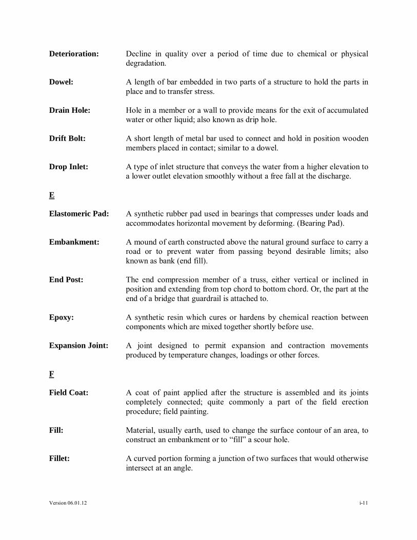
Deterioration: Decline in quality over a period of time due to chemical or physicaldegradation.
Dowel: A length of bar embedded in two parts of a structure to hold the parts inplace and to transfer stress.
Drain Hole: Hole in a member or a wall to provide means for the exit of accumulatedwater or other liquid; also known as drip hole.
Drift Bolt: A short length of metal bar used to connect and hold in position woodenmembers placed in contact; similar to a dowel.
Drop Inlet: A type of inlet structure that conveys the water from a higher elevation toa lower outlet elevation smoothly without a free fall at the discharge.
E
Elastomeric Pad: A synthetic rubber pad used in bearings that compresses under loads andaccommodates horizontal movement by deforming. (Bearing Pad).
Embankment: A mound of earth constructed above the natural ground surface to carry aroad or to prevent water from passing beyond desirable limits; alsoknown as bank (end fill).
End Post: The end compression member of a truss, either vertical or inclined inposition and extending from top chord to bottom chord. Or, the part at theend of a bridge that guardrail is attached to.
Epoxy: A synthetic resin which cures or hardens by chemical reaction betweencomponents which are mixed together shortly before use.
Expansion Joint: A joint designed to permit expansion and contraction movementsproduced by temperature changes, loadings or other forces.
F
Field Coat: A coat of paint applied after the structure is assembled and its jointscompletely connected; quite commonly a part of the field erectionprocedure; field painting.
Fill: Material, usually earth, used to change the surface contour of an area, toconstruct an embankment or to “fill” a scour hole.
Fillet: A curved portion forming a junction of two surfaces that would otherwiseintersect at an angle.
Version 06.01.12 i-12
Flange: The (usually) horizontal parts of a rolled I-shaped beam or of a built-upgirder extending transversely across the top and bottom of the web.
Footing: The enlarged, lower portion of a substructure, which distributes thestructure load either to the earth or to supporting piles. The most commonbridge application for footing is the concrete slab; footer is a colloquialterm for footing.
Forms: The molds that hold concrete in place while it is hardening; also knownas form work, shuttering; see LAGGING, STAY-IN-PLACE FORMS.
Foundation: The supporting material upon which the substructure portion of a bridgeis placed.
G
Galvanize: To coat with zinc.
Girder: A horizontal flexural member that is the main or primary support for astructure; any large beam, especially if built up.
Grout: Mortar having a sufficient water content to render it free-flowing, usedfor filling (grouting) the joints in masonry, for fixing anchor bolts and forfilling cored spaces; usually a thin mix of cement, water and sometimessand or admixtures.
Grouting: The process of filling in voids with grout.
Gutter: A paved ditch; area adjacent to a roadway curb used for drainage.
H
Hairline Cracks: Very narrow cracks (less than 1/64”) that form in the surface of concrete.
H-Beam: A rolled steel member having an H-shaped cross-section (flange widthequals beam depth) commonly used for piling; also H-pile.
High Strength Bolt: Bolt and nut made of high strength steel, usually complying with ASTMStandard A-325 or A-490.
I
I-Beam: A structural member with a cross−sectional shape similar to the capital letter "I".
Version 06.01.12 i-13
Inlet: An opening in the floor of a bridge leading to a drain; roadway drainagestructure which collects surface water and transfers it to pipes.
J
Jacking: The lifting of elements using a type of jack (e.g., hydraulic), sometimesacts as a temporary support system.
Jacket: A protective shell surrounding a pile made of fabric, concrete or othermaterial.
Joint: In masonry, the space between individual stones or bricks; in concrete, adivision in continuity of the concrete; in a truss, point at which membersof a truss are joined.
K
Keeper Plate: A plate, which is connected to a sole plate, designed to prohibit a beamfrom becoming dislodged from the bearing.
L
Lagging: Horizontal members spanning between piles to form a wall; forms usedto produce curved surfaces.
Longitudinal Bracing: Bracing that runs lengthwise with a bridge and provides resistanceagainst longitudinal movement and deformation of transverse members.
M
Maintenance: Repairs performed on a bridge structure to keep it at an adequate level ofservice.
Maintenance and Protection of Traffic: The management of vehicular and pedestrian trafficthrough a construction zone to ensure the safety of the public and theconstruction workforce.
Mortar: A mixture of portland cement, sand, and water laid between bricks,stones or blocks.
N
Necking: The elongation and contraction in area that occurs when a ductilematerial is stressed.

Version 06.01.12 i-14
Neoprene: A synthetic rubber-like material used in expansion joints and elastomericbearings.
O
Outlet: In hydraulics, the discharge end of drains, sewers, culverts or bridges.
Overlay: See WEARING SURFACE.
P
Parapet: A low wall along the outmost edge of the roadway of a bridge to protectvehicles and pedestrians.
Pedestal: Concrete or built-up metal member constructed on top of a bridge seat forthe purpose of providing a specific bearing seat elevation.
Pier: A substructure unit that supports the spans of a multi-span superstructureat an intermediate location between its abutments.
Pier cap: The topmost horizontal portion of a pier that distributes loads from thesuperstructure to the vertical pier elements.
Pile: A shaft-like linear member which carries loads to underlying rock or soilstrata.
Pile Bent: A row of driven or placed piles extending above the ground surfacesupporting a pile cap; see BENT.
Pile Cap: A slab or beam which acts to secure the piles in position laterally andprovides a bridge seat to receive and distribute superstructure loads.
Piping: Removal of fine particles from within a soil mass by flowing water,usually associated with culverts.
Plate Girder: A large I-shaped beam composed of a solid web plate with flange platesattached to the web plate by flange angles or fillet welds.
Pop-Out: Conical fragment broken out of a concrete surface by pressure fromreactive aggregate particles (spall).
Priming coat: The first coat of paint applied to the metal or other material of a bridge;also known as base coat, or primer.
Programmed Repair: Those repairs that may be performed in a scheduled program.

Version 06.01.12 i-15
Protective System: A system used to protect bridges from environmental forces that causesteel and concrete to deteriorate and timber to decay, typically a coatingsystem.
Q
R
Railing: A fence-like construction built at the outermost edge of the roadway orthe sidewalk portion of a bridge to protect pedestrians and vehicles.
Rapid Set Concrete: A high early strength hydraulic concrete that achieves a minimum designstrength of 5,000 PSI within 24 hours.
Rapid Setting Patching Material: A very early strength bag mix polymer concrete thatachieves a minimum design strength of 1,200 PSI within 2 hours.
Rebar: See REINFORCING BAR.
Rehabilitation: Significant repair work to a structure.
Reinforced Concrete: Concrete with steel reinforcing bars embedded in it to supply increasedtensile strength and durability.
Reinforcing Bar: A steel bar, plain or with a deformed surface, which bonds to the concreteand supplies tensile strength to the concrete.
Resurfacing: A layer of wearing surface material that is put over the approach or decksurface in order to create a more uniform riding surface.
Rip-Rap: Stones, blocks of concrete or other objects placed upon river and streambeds and banks, lake, tidal or other shores to prevent scour by water flowor wave action.
S
Safety Curb: A curb between 9 inches and 24 inches wide serving as a limited userefuge or walkway for pedestrians crossing a bridge.
Scaling: The gradual disintegration of a concrete surface due to the failure of thecement paste caused by chemical attack or freeze/thaw cycles.
Scour: Removal of a streambed or bank area by stream flow; erosion ofstreambed or bank material due to flowing water; often considered asbeing localized around piers and abutments of bridges.

Version 06.01.12 i-16
Scour Protection: Protection of submerged material by steel sheet piling, rip rap, concretelining, or combination thereof.
Scupper: An opening in the deck of a bridge to provide means for wateraccumulated upon the roadway surface to drain.
Section Loss: Loss of a member's cross sectional area usually by corrosion or decay.
Shim: A thin plate inserted between two elements to fix their relative positionand to transmit bearing stress.
Shop: A factory or workshop.
Shoring: A strut or prop placed against or beneath a structure to restrainmovement; temporary soil retaining structure.
Slope Protection: A thin surfacing of rip rap, concrete, filter fabric or other materialdeposited upon a sloped surface to prevent its disintegration by rain, windor other erosive action; a slope paving - concrete.
Spall: Depression in concrete caused by a separation of a portion of the surfaceconcrete, revealing a fracture parallel with or slightly inclined to thesurface.
Specifications: A detailed description of requirements, materials, tolerances, etc., forconstruction which are not shown on the drawings; also known as specs.
Spillway: A channel used to carry water away from the top of a slope to anadjoining outlet.
Standard Barrier: A low, reinforced concrete wall wider at the base, tapering vertically tonear mid-height, and then continuing straight up to its top. The shape isdesigned to direct automotive traffic back toward its own lane of traveland prevent crossing of a median or leaving the roadway. Commonlyused on new and reconstructed bridges in place of decorative balustrades,railings or parapets.
Stay-In-Place Forms: A corrugated metal sheet for forming deck concrete that will remain inplace after the concrete has set; the forms do not contribute to deckstructural capacity after the deck has cured; see FORMS, S.I.P FORMS.
Stirrup: U-shaped bar used as a connection device in timber and metal bridges; U-shaped bar placed in concrete to resist diagonal tension (shear) stresses.
Substructure: The abutments and piers built to support the bridge superstructure.

Version 06.01.12 i-17
Superstructure: The entire portion of a bridge structure that primarily receives andsupports traffic loads and in turn transfers these loads to the bridgesubstructure.
Surface Corrosion: Rust that has not yet caused measurable section loss.
Sway Bracing: Diagonal brace located at the top of a through truss, transverse to thetruss and usually in a vertical plane, to resist transverse horizontal forces.
Swedged Bolt: Bolt with deformations to increase bond in concrete; see ANCHORBOLT.
T
Timber: Wood suitable for construction purposes.
Toe of Slope: The location defined by the intersection of the embankment with theexisting ground at a lower elevation; also known as toe.
Traffic Control: Modification of normal traffic patterns by signs, cones, flagmen, etc.
U
V
Voids: An empty or unfilled space in concrete.
W
Washer: A small metal ring used beneath the nut or the head of a bolt to distributethe load or reduce galling during tightening.
Wearing Surface: The topmost layer of material applied upon a roadway to receive thetraffic loads and to resist the resulting disintegrating action; also knownas wearing course.
Weld: A joint between pieces of metal at faces that have been made plastic andcaused to flow together by heat or pressure.
Weep Hole: A hole in a concrete element (abutment backwall or retaining wall) usedto drain water from the soil behind the element; any small hole installedfor drainage.
Wingwall: The retaining wall extension of an abutment intended to restrain and holdin place the material under the approach slab or approach roadwayembankment.

Version 06.01.12 i-18
X
Y
Z

Version 06.01.12 1-19
1 Introduction
1.1 Purpose of This Manual
This manual is intended as a reference for preventative and corrective maintenance activitiesapplicable to state and local bridge structures.
This manual is designed to address the most common types of bridge structure distress byoutlining practical procedures for corrective and preventive maintenance. These procedures arenot meant to be all-inclusive, or to rule out other maintenance procedures. This manual does notaddress the environmental, historic preservation, or safety implications of these activities.
Some Federal, State, and local laws or rules or regulations may render some proceduresinappropriate in specific situations. On-site supervisors are responsible for ensuring thatprocedures considered are consistent with environmental standards and safety codes within thejurisdictions involved, and that any permits required are obtained before starting work.
1.2 Bridge Components
Some common terms are used to define the components of each bridge. Personnel responsiblefor bridge maintenance should know the basic components, their role, and their significance tohelp with ranking recommendations in a maintenance plan.
Deck: Supports the roadway on which traffic flows, and also distributes traffic (live) loads anddead loads.
Superstructure: Supports loads transmitted through the deck.
Bearings: Support that transfer loads from the superstructure to the substructure, whilepermitting limited rotation and longitudinal movement.
Substructure: Elements that transfer all loads from the superstructure to the ground.
Expansion Joint: Assembly or material designed to safely absorb the expansion and contractionof the superstructure and to protect the bearings from water and debris.
Bridge Typical Section
Deck Superstructure
Bearings
Substructure

Chapter 1 Introduction
Version 06.01.12 1-20
Bridge Elevation View
1.3 Bridge Culvert Components
Some common terms are used to define the components of each culvert. Personnel responsiblefor culvert maintenance should know the basic components, their role, and their significance tohelp with ranking recommendations in a maintenance plan.
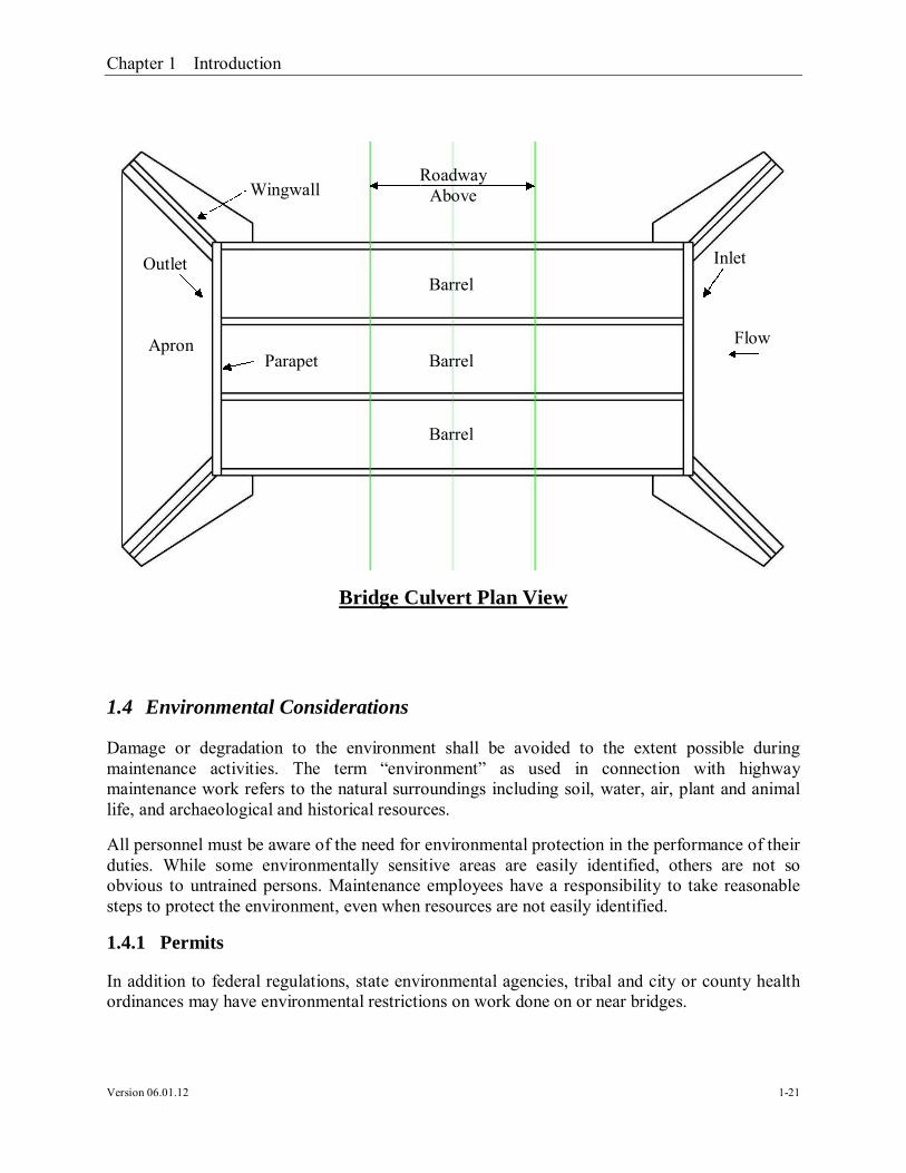
Apron: area that is intended to eliminate the potential for scour caused by water exiting theculvert.
Barrel: opening that will allow water to pass unobstructed under roadway
Wingwall: A tapering wall that originates from the corner of the culvert and is intended to retainsoil under the roadway.
Parapet: short wall across top of openings used to retain fill material
Toe Wall: A full width wall that extends downward from the bottom of the culvert at both ends.
Bridge Culvert Elevation View
IntermediateBent
WingwallBarrier
Abutment
Toe of Slope
ApproachSlab
Wingwall
Barrel Barrel Barrel
Parapet
Toe Wall
Chapter 1 Introduction
Version 06.01.12 1-21
Bridge Culvert Plan View
1.4 Environmental Considerations
Damage or degradation to the environment shall be avoided to the extent possible duringmaintenance activities. The term “environment” as used in connection with highwaymaintenance work refers to the natural surroundings including soil, water, air, plant and animallife, and archaeological and historical resources.
All personnel must be aware of the need for environmental protection in the performance of theirduties. While some environmentally sensitive areas are easily identified, others are not soobvious to untrained persons. Maintenance employees have a responsibility to take reasonablesteps to protect the environment, even when resources are not easily identified.
1.4.1 Permits
In addition to federal regulations, state environmental agencies, tribal and city or county healthordinances may have environmental restrictions on work done on or near bridges.
Barrel
Barrel
Barrel
Wingwall
Flow
RoadwayAbove
Parapet
Inlet
Apron
Outlet
Chapter 1 Introduction
Version 06.01.12 1-22
Before initiating bridge repair activities, the District Maintenance Engineer, or local municipalitywill confirm what, if any, environmental permits are required.
1.4.2 Coordination
Georgia DOT’s Office of Environmental Services and the District Environmentalist can provideinformation on identifying, protecting, and avoiding or minimizing harm to environmentalresources.
Before beginning work in the field, contact the District Maintenance Office to inquire if anyMemorandum of Agreements (MOA) have been reached between GDOT and any regulatoryagency or authority.
1.4.3 Documents
All personnel shall be familiar with and adhere to the following:
“WORKSITE EROSION CONTROL MANUAL” “REQUIREMENTS FOR GDOT MAINTENANCE ACTIVITIES AND
OPERATIONS” “GENERAL FACILITY ENVIRONMENTAL GUIDELINES”
1.5 General Notes for All Maintenance and Repair Activities
The following notes apply to all maintenance discussed in this manual.
1. All work shall adhere to the Georgia Standard Specifications for Construction, CurrentEdition, and Current Supplemental Specifications.
2. No material shall be salvaged.
3. The foreman shall dispose of materials from the existing bridge structures.
4. It shall be the responsibility of the foreman to locate or furnish an environmentallyapproved disposal area as necessary for this project and disposal shall be accomplished ina manner acceptable to and as directed by the engineer. Disposal sites shall be approvedby the District Environmentalist prior to any work on this item.
5. All work will be completed within the existing right-of-way.

Chapter 1 Introduction
Version 06.01.12 1-23
6. In addition to contacting the Utility Protection Center (1-800-282-7411), the managerresponsible for the maintenance activities shall also contact each utility owner. Theforeman shall advise the utility company owner/representative at least one week prior toany work in their respective areas. The owner responsible for the work will beresponsible for any damages to any utility damages to any utility attachments resultingfrom this work.

Chapter 2 Bridge Structure Maintenance Activities
Version 06.01.12 2-24
2 Bridge Structure Maintenance Activities
Despite even the most aggressive preventive maintenance program, some deterioration ordamage of elements will occur. This chapter presents corrective activities that can be performedto repair typical deterioration or damage. The activities are broken down into eight separatecategories:
1. Activity 800 – Bridge Joint Sealing2. Activity 805 – Header Joint Reconstruction/Repair3. Activity 810 – Deck Repair4. Activity 815 – Bridge Curb/Rail Repair5. Activity 820 – Culvert Repair6. Activity 825 – Pile Replacement and Related Repairs7. Activity 830 – Repair Main Structural Members8. Activity 845 – Other Bridge Maintenance

Chapter 2 Bridge Structure Maintenance Activities
Version 06.01.12 2-25
Activity 800.01 – Bridge Deck Joint Sealing (Silicone)
General Notes:Verify all dimensions and elevations in the field prior to ordering materials or buildingforms. Light lines indicate the existing structure and heavy lines indicate the new structure.
Clean existing bridge expansion joints of all dirt, refuse, and existing sealant by sandblasting. Seal joints using silicone sealant (Type D) as per sub-sections 461.3.05.C and833.2.06 of the Georgia DOT Specifications.
Material Specifications: None
Safety Traffic Control
o GDOT Operations Work Zone Traffic Control, oro GDOT Standard Drawings 9100 thru 9107 and MUTCD Part 6 – Temporary
Traffic Control
Georgia Standard Specifications Section 461 – Sealing Roadway and Bridge Joint and Cracks
Georgia Special Provisions & Supplemental Specifications: None
Qualified Products List: QPL 15 QPL 60
Before Repair After Repairs


Chapter 2 Bridge Structure Maintenance Activities
Version 06.01.12 2-28
Activity 800.02 – Bridge Deck Joint Sealing (Evazote)
General Notes:Verify all dimensions and elevations in the field prior to ordering materials or buildingforms. Light lines indicate the existing structure and heavy lines indicate the new structure.
Clean existing bridge expansion joints of all dirt, refuse, and existing sealant and seal jointsusing low density polyethylene seal as per section 449.2.D of the Georgia DOTSpecifications.
Material Specifications: None
Safety Traffic Control
o GDOT Operations Work Zone Traffic Control, oro GDOT Standard Drawings 9100 thru 9107 and MUTCD Part 6 – Temporary
Traffic Control
Georgia Standard Specifications Section 461 – Bridge Deck Joint Seals
o (Low-Density, Closed Cell, Cross-Linked, Ethylene Vinyl Acetate, PolyethyleneCopolymer, Nitrogen-Blown Seal)
Georgia Special Provisions & Supplemental Specifications: None
Qualified Products List: None
Before Repair After Repairs


Chapter 2 Bridge Structure Maintenance Activities
Version 06.01.12 2-31
Activity 805.01 – Header Joint Reconstruction – Asphalt Overlay
General Notes:Place and tie all reinforcing steel in accordance with the Georgia DOT Specifications. Donot weld reinforcing steel.
Verify all dimensions and elevations in the field prior to ordering materials or buildingforms. Light lines indicate the existing structure and heavy lines indicate the new structure.
Thoroughly clean existing reinforcement of concrete scale and rust by sand blasting beforebonding into new construction.
Apply epoxy resin adhesive Type II to all hardened concrete surfaces just prior to pouring theconcrete, see section 886 of the Georgia DOT Specifications.
Refer to Activity 800.01 – Bridge Deck Joint Sealing (Silicone) or 800.02 – Bridge DeckJoint Seal (Evazote), for additional details. Match existing joint size and type.
Material Specifications: Concrete: 24 – Hour, Class AA, ƒ′c = 3,500 psi
: Rapid Setting Patching Material Reinforcing Steel: Grade 60, ƒy = 60,000 psi
Safety Traffic Control
o GDOT Operations Work Zone Traffic Control, oro GDOT Standard Drawings 9100 thru 9107 and MUTCD Part 6 – Temporary
Traffic Control
Before Repair After Repairs

Chapter 2 Bridge Structure Maintenance Activities
Version 06.01.12 2-32
Georgia Standard Specifications Section 500 – Concrete Structures Section 504 – Twenty-Four Hour Accelerated Strength Concrete Section 511 – Reinforcement Steel Section 521 – Patching Concrete Bridge Deck Section 886 – Epoxy Resin Adhesive
Georgia Special Provisions & Supplemental Specifications: None
Qualified Products List: QPL-10 List of Approved Concrete Plants QPL-12 Reinforcement Steel Fabricators QPL-15 Epoxy Resin Adhesives QPL-27 Rapid Setting Patching Material


Chapter 2 Bridge Structure Maintenance Activities
Version 06.01.12 2-35
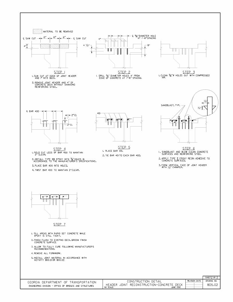
Activity 805.02 – Header Joint Reconstruction – Concrete Deck
General Notes:Place and tie all reinforcing steel in accordance with the Georgia DOT Specifications. Donot weld reinforcing steel.
Verify all dimensions and elevations in the field prior to ordering materials or buildingforms. Light lines indicate the existing structure and heavy lines indicate the new structure.
Apply epoxy resin adhesive Type II to all hardened concrete surfaces just prior to pouring theconcrete, see section 886 of the Georgia DOT Specifications.
Thoroughly clean existing reinforcement of concrete scale and rust by sand blasting beforebonding into new construction.
Refer to Activity 800.01 – Bridge Deck Joint Sealing (Silicone) or 800.02 – Bridge DeckJoint Seal (Evazote), for additional details. Match existing joint size and type.
Material Specifications: Concrete: 24 – Hour, Class AA, ƒ′c = 3,500 psi Reinforcing Steel: Grade 60, ƒy = 60,000 psi
Safety Traffic Control
o GDOT Operations Work Zone Traffic Control, oro GDOT Standard Drawings 9100 thru 9107 and MUTCD Part 6 – Temporary
Traffic Control
Before Repair After Repairs
Chapter 2 Bridge Structure Maintenance Activities
Version 06.01.12 2-36
Georgia Standard Specifications Section 500 – Concrete Structures Section 504 – Twenty-Four Hour Accelerated Strength Concrete Section 511 – Reinforcement Steel Section 886 – Epoxy Resin Adhesive
Georgia Special Provisions & Supplemental Specifications: None
Qualified Products List: QPL-10 List of Approved Concrete Plants QPL-12 Reinforcement Steel Fabricators QPL-15 Epoxy Resin Adhesives


Chapter 2 Bridge Structure Maintenance Activities
Version 06.01.12 2-39
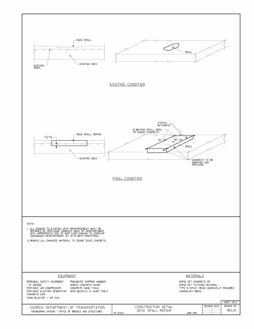
Activity 810.01 – Deck Spall Repair
General Notes:Verify all dimensions and elevations in the field prior to ordering materials or buildingforms. Light lines indicate the existing structure and heavy lines indicate the new structure.
Apply epoxy resin adhesive Type II to all hardened concrete surfaces just prior to pouring theconcrete, see section 886 of the Georgia DOT Specifications.
Thoroughly clean existing reinforcement of concrete scale and rust before bonding into newconstruction.
Material Specifications: Concrete: 24-Hour, Class AA, ƒ′c = 3,500 psi
: Rapid Setting Patching MaterialSafety
Traffic Controlo GDOT Operations Work Zone Traffic Control, oro GDOT Standard Drawings 9100 thru 9107 and MUTCD Part 6 – Temporary
Traffic Control
Georgia Standard Specifications Section 504 – Twenty-Four Hour Accelerated Strength Concrete Section 886 – Epoxy Resin Adhesive Section 934 – Rapid Setting Patching Material for Portland Cement Concrete
Georgia Special Provisions & Supplemental Specifications: Section 521 – Patching Concrete Bridge Deck
Before Repair After Repairs
Chapter 2 Bridge Structure Maintenance Activities
Version 06.01.12 2-40
Qualified Products List: QPL-10 List of Approved Concrete Plants QPL-15 Epoxy Resin Adhesive QPL-27 Rapid Setting Patching Material

Chapter 2 Bridge Structure Maintenance Activities
Version 06.01.12 2-43
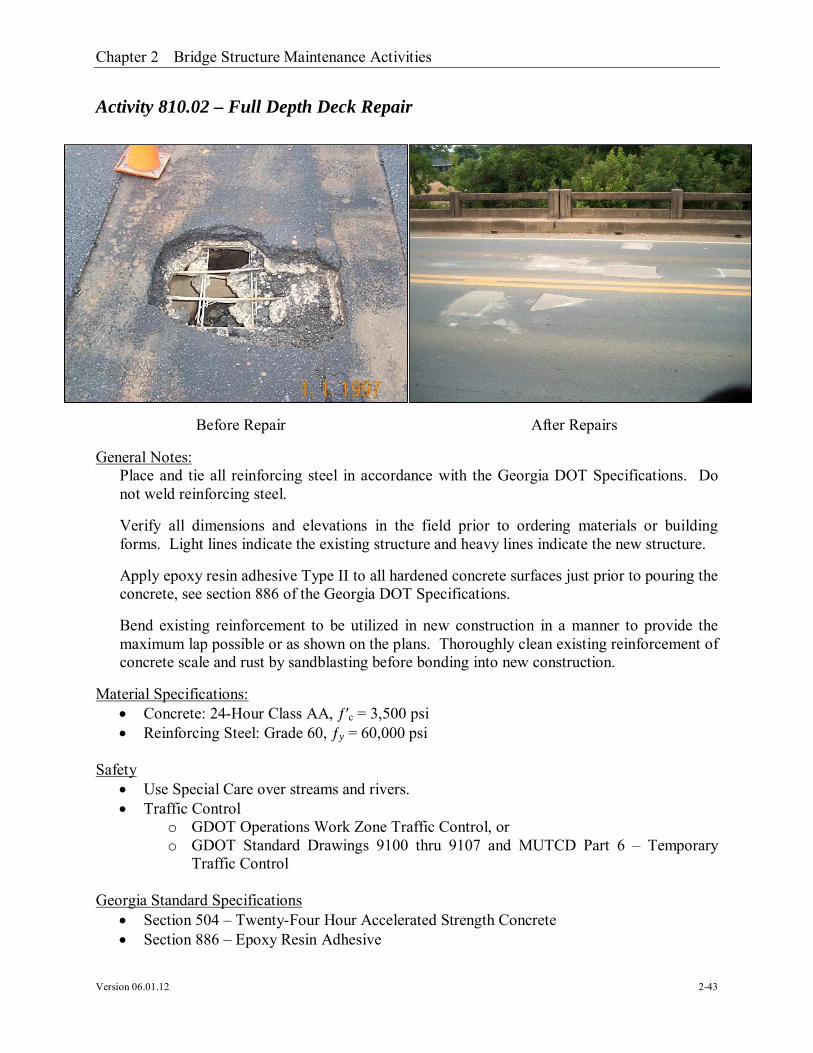
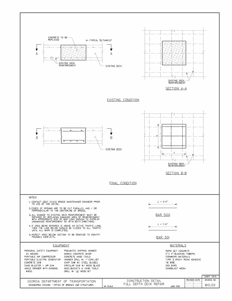
Activity 810.02 – Full Depth Deck Repair
General Notes:Place and tie all reinforcing steel in accordance with the Georgia DOT Specifications. Donot weld reinforcing steel.
Verify all dimensions and elevations in the field prior to ordering materials or buildingforms. Light lines indicate the existing structure and heavy lines indicate the new structure.
Apply epoxy resin adhesive Type II to all hardened concrete surfaces just prior to pouring theconcrete, see section 886 of the Georgia DOT Specifications.
Bend existing reinforcement to be utilized in new construction in a manner to provide themaximum lap possible or as shown on the plans. Thoroughly clean existing reinforcement ofconcrete scale and rust by sandblasting before bonding into new construction.
Material Specifications: Concrete: 24-Hour Class AA, ƒ′c = 3,500 psi Reinforcing Steel: Grade 60, ƒy = 60,000 psi
Safety Use Special Care over streams and rivers. Traffic Control
o GDOT Operations Work Zone Traffic Control, oro GDOT Standard Drawings 9100 thru 9107 and MUTCD Part 6 – Temporary
Traffic Control
Georgia Standard Specifications Section 504 – Twenty-Four Hour Accelerated Strength Concrete Section 886 – Epoxy Resin Adhesive
Before Repair After Repairs

Chapter 2 Bridge Structure Maintenance Activities
Version 06.01.12 2-44
Georgia Special Provisions & Supplemental Specifications: None
Qualified Products List: QPL-10 – List of Approved Concrete Plants QPL-15 – Epoxy Resin Adhesive


Chapter 2 Bridge Structure Maintenance Activities
Version 06.01.12 2-47
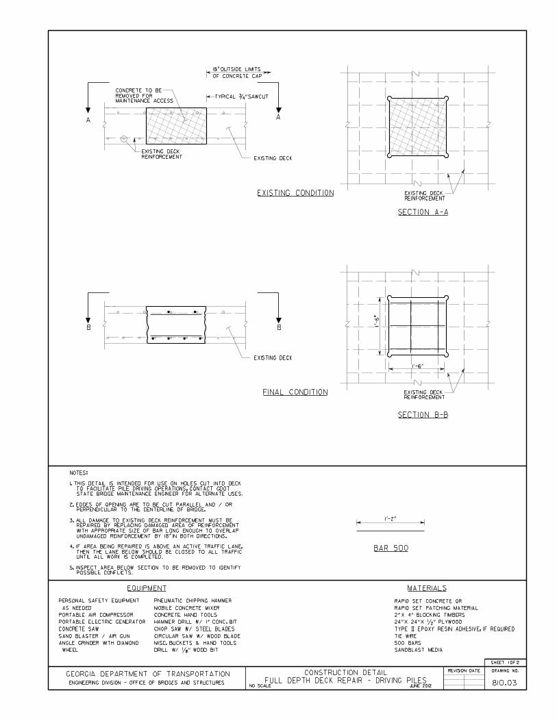
Activity 810.03 – Full Depth Deck Repair – Driving Piles
General Notes:Place and tie all reinforcing steel in accordance with the Georgia DOT Specifications. Donot weld reinforcing steel.
Verify all dimensions and elevations in the field prior to ordering materials or buildingforms. Light lines indicate the existing structure and heavy lines indicate the new structure.
Apply epoxy resin adhesive Type II to all hardened concrete surfaces just prior to pouring theconcrete, see section 886 of the Georgia DOT Specifications.
Bend existing reinforcement to be utilized in new construction in a manner to provide themaximum lap possible or as shown on the plans. Thoroughly clean existing reinforcement ofconcrete scale and rust by sandblasting before bonding into new construction.
Material Specifications: Concrete: 24-Hour Class AA, ƒ′c = 3,500 psi Rapid Setting Patching Material Reinforcing Steel: Grade 60, ƒy = 60,000 psi
Safety Traffic Control
o GDOT Operations Work Zone Traffic Control, oro GDOT Standard Drawings 9100 thru 9107 and MUTCD Part 6 – Temporary
Traffic Control
Before Repair After Repairs
Chapter 2 Bridge Structure Maintenance Activities
Version 06.01.12 2-48
Georgia Standard Specifications Section 504 – Twenty-Four Hour Accelerated Strength Concrete Section 886 – Epoxy Resin Adhesive Section 934 – Rapid Setting Patching Material for Portland Cement Concrete
Georgia Special Provisions & Supplemental Specifications: None
Qualified Products List: QPL-10 – List of Approved Concrete Plants QPL-15 – Epoxy Resin Adhesive QPL-27 – Rapid Setting Patching Material


Chapter 2 Bridge Structure Maintenance Activities
Version 06.01.12 2-51
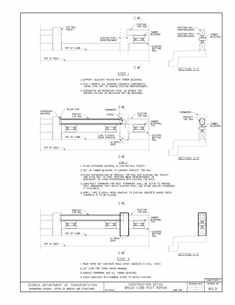
Activity 815.01 – Brush Curb Post Repair
General Notes:Place and tie all reinforcing steel in accordance with the Georgia DOT Specifications. Donot weld reinforcing steel.
Verify all dimensions and elevations in the field prior to ordering materials or buildingforms. Light lines indicate the existing structure and heavy lines indicate the new structure.
Apply epoxy resin adhesive Type II to all hardened concrete surfaces just prior to pouring theconcrete, see section 886 of the Georgia DOT Specifications.
Bend existing reinforcement to be utilized in new construction in a manner to provide themaximum lap possible or as shown on the plans. Thoroughly clean existing reinforcement ofconcrete scale and rust before bonding into new construction.
Material Specifications: Concrete: Class AA, ƒ′c = 3,500 psi Reinforcing Steel: Grade 60, ƒy = 60,000 psi
Safety Traffic Control
o GDOT Operations Work Zone Traffic Control, oro GDOT Standard Drawings 9100 thru 9107 and MUTCD Part 6 – Temporary
Traffic Control Use special care near streams and rivers.
Before Repair After Repairs

Chapter 2 Bridge Structure Maintenance Activities
Version 06.01.12 2-52
Georgia Standard Specifications Section 500 – Concrete Structures Section 511 – Reinforcement Steel Section 886 – Epoxy Resin Adhesive
Georgia Special Provisions & Supplemental Specifications: None
Qualified Products List: QPL-10 List of Approved Concrete Plants QPL-12 Reinforcement Steel Fabricators QPL-15 Epoxy Resin Adhesives QPL-19 Bar Supports QPL-20 (A) Preformed Joint Filler and (B) Preformed Foam Joint Filler


Chapter 2 Bridge Structure Maintenance Activities
Version 06.01.12 2-55
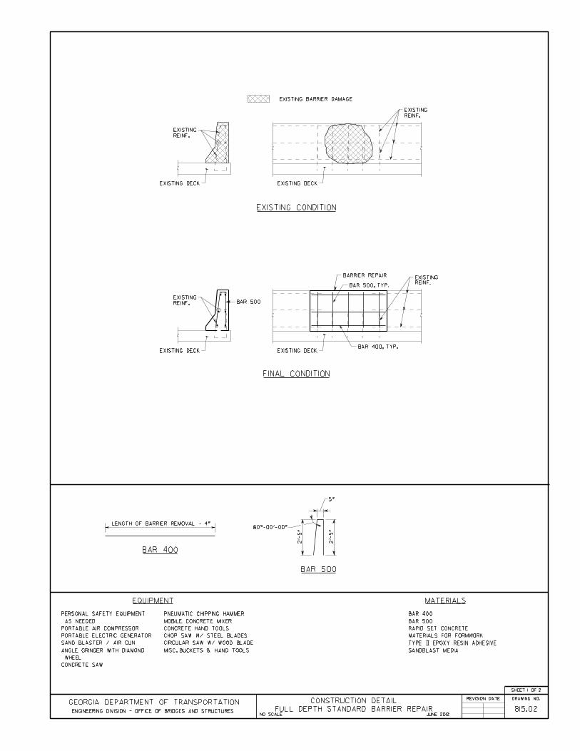
Activity 815.02 – Full Depth Standard Barrier Repair
General Notes:Place and tie all reinforcing steel in accordance with the Georgia DOT Specifications. Donot weld reinforcing steel.
Verify all dimensions and elevations in the field prior to ordering materials or buildingforms. Light lines indicate the existing structure and heavy lines indicate the new structure.
Apply epoxy resin adhesive Type II to all hardened concrete surfaces just prior to pouring theconcrete, see section 886 of the Georgia DOT Specifications.
Bend existing reinforcement to be utilized in new construction in a manner to provide themaximum lap possible or as shown on the plans. Thoroughly clean existing reinforcement ofconcrete scale and rust by sand blasting before bonding into new construction.
Material Specifications: Concrete: Class AA, ƒ′c = 3,500 psi Reinforcing Steel: Grade 60, ƒy = 60,000 psi
Safety Traffic Control
o GDOT Operations Work Zone Traffic Control, oro GDOT Standard Drawings 9100 thru 9107 and MUTCD Part 6 – Temporary
Traffic Control Use special care near streams and rivers.
Before Repair After Repairs

Chapter 2 Bridge Structure Maintenance Activities
Version 06.01.12 2-56
Georgia Standard Specifications Section 500 – Concrete Structures Section 511 – Reinforcement Steel Section 621 – Concrete Barrier Section 886 – Epoxy Resin Adhesive
Georgia Special Provisions & Supplemental Specifications: None
Qualified Products List: QPL-10 List of Approved Concrete Plants QPL-12 Reinforcement Steel Fabricators QPL-15 Epoxy Resin Adhesives QPL-19 Bar Supports QPL-20 (A) Preformed Joint Filler and (B) Preformed Foam Joint Filler


Chapter 2 Bridge Structure Maintenance Activities
Version 06.01.12 2-59
Activity 815.03 – Standard Barrier Top Spall Repair
General Notes:Place and tie all reinforcing steel in accordance with the Georgia DOT Specifications. Donot weld reinforcing steel.
Verify all dimensions and elevations in the field prior to ordering materials or buildingforms. Light lines indicate the existing structure and heavy lines indicate the new structure.
Apply epoxy resin adhesive Type II to all hardened concrete surfaces just prior to pouring theconcrete, see section 886 of the Georgia DOT Specifications.
Bend existing reinforcement to be utilized in new construction in a manner to provide themaximum lap possible or as shown on the plans. Thoroughly clean existing reinforcement ofconcrete scale and rust by sand blasting before bonding into new construction.
Material Specifications: Concrete: Class AA, ƒ′c = 3,500 psi Reinforcing Steel: Grade 60, ƒy = 60,000 psi
Safety Traffic Control
o GDOT Operations Work Zone Traffic Control, oro GDOT Standard Drawings 9100 thru 9107 and MUTCD Part 6 – Temporary
Traffic Control Use special care near streams and rivers.
Before Repair After Repairs

Chapter 2 Bridge Structure Maintenance Activities
Version 06.01.12 2-60
Georgia Standard Specifications Section 500 – Concrete Structures Section 511 – Reinforcement Steel Section 886 – Epoxy Resin Adhesive
Georgia Special Provisions & Supplemental Specifications: None
Qualified Products List: QPL-10 List of Approved Concrete Plants QPL-12 Reinforcement Steel Fabricators QPL-15 Epoxy Resin Adhesives QPL-19 Bar Supports QPL-20 (A) Preformed Joint Filler and (B) Preformed Foam Joint Filler


Chapter 2 Bridge Structure Maintenance Activities
Version 06.01.12 2-63
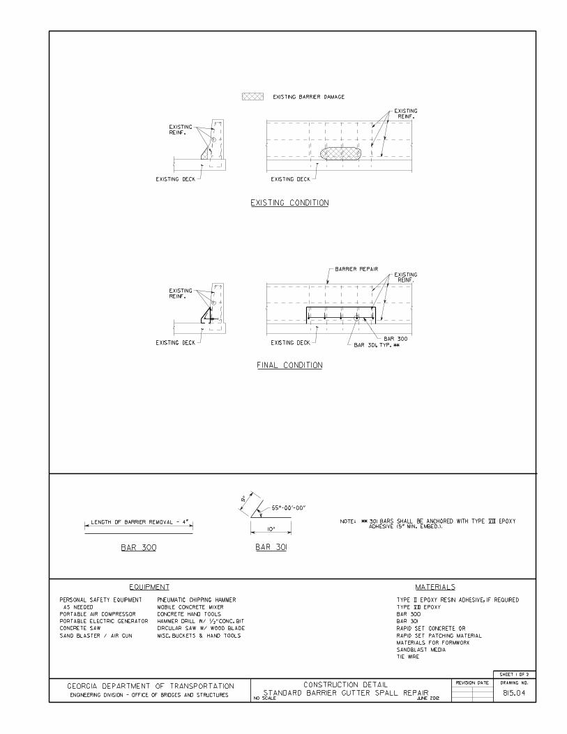
Activity 815.04 - Standard Barrier Gutter Spall Repair
General Notes:Place and tie all reinforcing steel in accordance with the Georgia DOT Specifications. Donot weld reinforcing steel.
Verify all dimensions and elevations in the field prior to ordering materials or buildingforms. Light lines indicate the existing structure and heavy lines indicate the new structure.
Apply epoxy resin adhesive Type II to all hardened concrete surfaces just prior to pouring theconcrete, see section 886 of the Georgia DOT Specifications.
Bend existing reinforcement to be utilized in new construction in a manner to provide themaximum lap possible or as shown on the plans. Thoroughly clean existing reinforcement ofconcrete scale and rust by sand blasting before bonding into new construction.
Material Specifications: Concrete: Class AA, ƒ′c = 3,500 psi Reinforcing Steel, Grade 60, ƒy = 60,000 psi
Safety Traffic Control
o GDOT Operations Work Zone Traffic Control, oro GDOT Standard Drawings 9100 thru 9107 and MUTCD Part 6 – Temporary
Traffic Control Use special care near streams and rivers.
Before Repair After Repairs

Chapter 2 Bridge Structure Maintenance Activities
Version 06.01.12 2-64
Georgia Standard Specifications Section 500 – Concrete Structures Section 511 – Reinforcement Steel Section 886 – Epoxy Resin Adhesive
Georgia Special Provisions & Supplemental Specifications: None
Qualified Products List: QPL-10 List of Approved Concrete Plants QPL-12 Reinforcement Steel Fabricators QPL-15 Epoxy Resin Adhesives


Chapter 2 Bridge Structure Maintenance Activities
Version 06.01.12 2-67
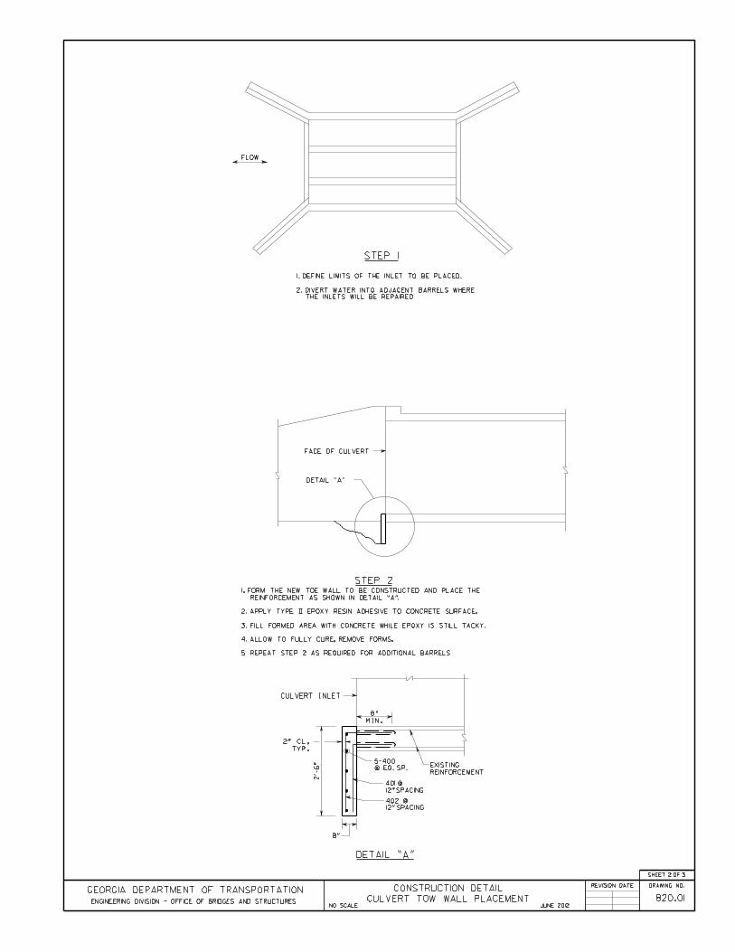
Activity 820.01 – Culvert Toe Wall Placement
General Notes:Coordinate all work in the stream with the District Environmentalist.
Traffic can be maintained onsite during this activity.
Place and tie all reinforcing steel in accordance with the Georgia DOT Specifications. Donot weld reinforcing steel.
Verify all dimensions and elevations in the field prior to ordering materials or buildingforms. Light lines indicate the existing structure and heavy lines indicate the new structure.
Apply epoxy resin adhesive Type II to all hardened concrete surfaces just prior to pouring theconcrete, see section 886 of the Georgia DOT Specifications.
All reinforcing steel shall be epoxy coated.
Material Specifications: Concrete: Class A, ƒ′c = 3,000 psi Reinforcing Steel, Grade 60, ƒy = 60,000 psi
Safety Traffic Control
o GDOT Operations Work Zone Traffic Control, oro GDOT Standard Drawings 9100 thru 9107 and MUTCD Part 6 – Temporary
Traffic Control Use special care near streams and rivers.
Before Repair After Repairs

Chapter 2 Bridge Structure Maintenance Activities
Version 06.01.12 2-68
Georgia Standard Specifications Section 500 – Concrete Structures Section 511 – Reinforcement Steel Section 514 – Epoxy Coated Steel Reinforcement Section 886 – Epoxy Resin Adhesive
Georgia Special Provisions & Supplemental Specifications: None
Qualified Products List: QPL-10 List of Approved Concrete Plants QPL-12 Reinforcement Steel Fabricators QPL-15 Epoxy Resin Adhesives QPL-38 Epoxy Powders for Coating Steel Reinforcing Bars & Coated Tie Wires
for Epoxy Coated Reinforcing Bars


Chapter 2 Bridge Structure Maintenance Activities
Version 06.01.12 2-72
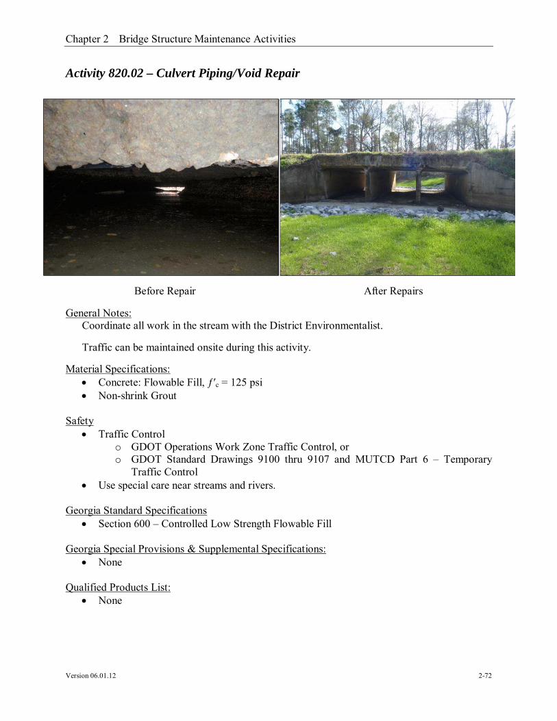
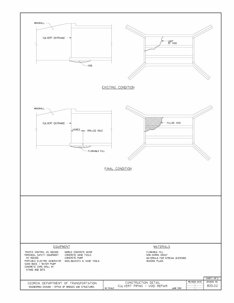
Activity 820.02 – Culvert Piping/Void Repair
General Notes:Coordinate all work in the stream with the District Environmentalist.
Traffic can be maintained onsite during this activity.
Material Specifications: Concrete: Flowable Fill, ƒ′c = 125 psi Non-shrink Grout
Safety Traffic Control
o GDOT Operations Work Zone Traffic Control, oro GDOT Standard Drawings 9100 thru 9107 and MUTCD Part 6 – Temporary
Traffic Control Use special care near streams and rivers.
Georgia Standard Specifications Section 600 – Controlled Low Strength Flowable Fill
Georgia Special Provisions & Supplemental Specifications: None
Qualified Products List: None
Before Repair After Repairs


Chapter 2 Bridge Structure Maintenance Activities
Version 06.01.12 2-75
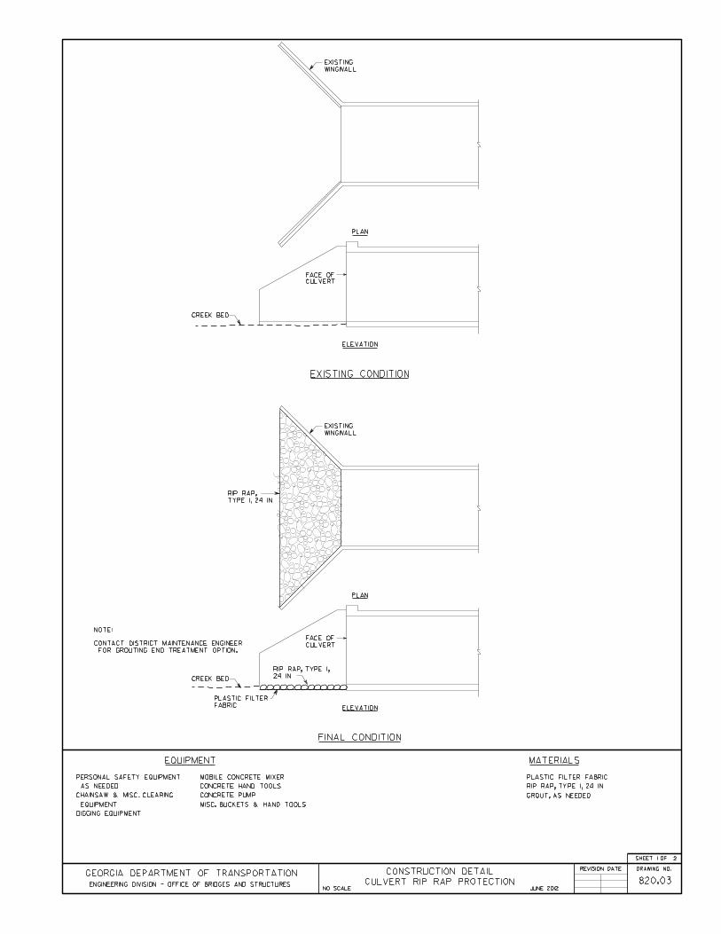
Activity 820.03 – Culvert Rip Rap Protection
General Notes:Coordinate all work in the stream with the District Environmentalist.
Verify all dimensions and elevations in the field prior to ordering material.
Material Specifications: None
Safety Traffic Control
o GDOT Operations Work Zone Traffic Control, oro GDOT Standard Drawings 9100-9107 and MUTCD Part 6 – Temporary Traffic
Control Use special care near streams and rivers.
Georgia Standard Specifications: Section 603 – Rip Rap Section 805 – Rip Rap and Curbing Stone Section 881 – Fabrics
Georgia Special Provisions & Supplemental Specifications: None
Qualified Products List: QPL-28 Filter Fabric
Before Repair After Repairs


Chapter 2 Bridge Structure Maintenance Activities
Version 06.01.12 2-78
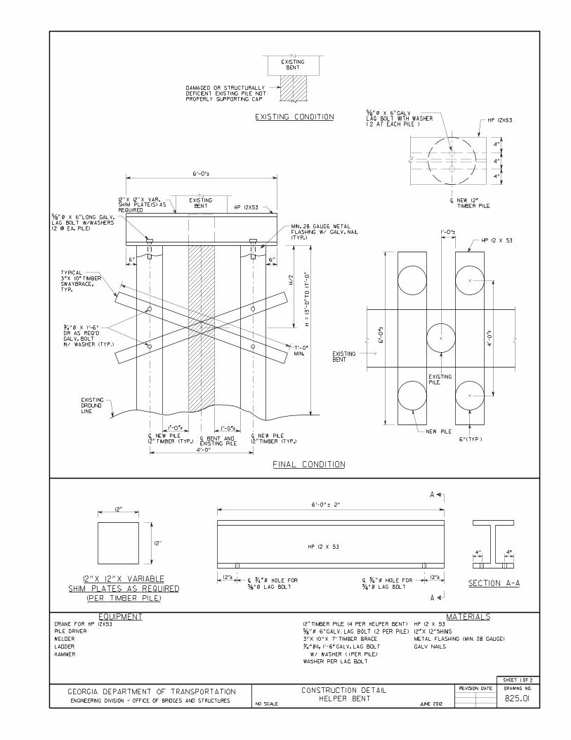
Activity 825-01 – Helper Bent (Temporary Repair)
General Notes:Coordinate all work in the stream/river with the District Environmentalist.
This is a temporary repair. Replace or rehabilitate bridge within 5 years of performing thiswork.
Verify all dimensions and elevations in the field prior to ordering materials or buildingforms. Light lines indicate the existing structure and heavy lines indicate the new structure.
All steel components shall be galvanized in accordance with ASTM A 123.
Refer to Activity 810.03 – Full Depth Deck Repair – Driving Piles, for additional details.
Material Specifications: Structural Steel: Grade 50, ƒy = 50,000 psi
Safety Traffic Control
o GDOT Operations Work Zone Traffic Control, oro GDOT Standard Drawings 9100 thru 9107 and MUTCD Part 6 – Temporary
Traffic Control Use special care near streams and rivers.
Before Repair After Repairs

Chapter 2 Bridge Structure Maintenance Activities
Version 06.01.12 2-79
Georgia Standard Specifications Section 501 – Steel Structures Section 502 – Timber Structures Section 520 – Piling Section 535 – Painting Structures Section 860 – Lumber and Timber Section 861 – Piling and Round Tiber Section 861 – Preservative Treatment of Timber Products
Georgia Special Provisions & Supplemental Specifications: None
Qualified Products List: QPL-50 Wood Preserving Plants QPL-53 Galvanizers QPL-59 Miscellaneous Metal Fabricators

Chapter 2 Bridge Structure Maintenance Activities
Version 06.01.12 2-82
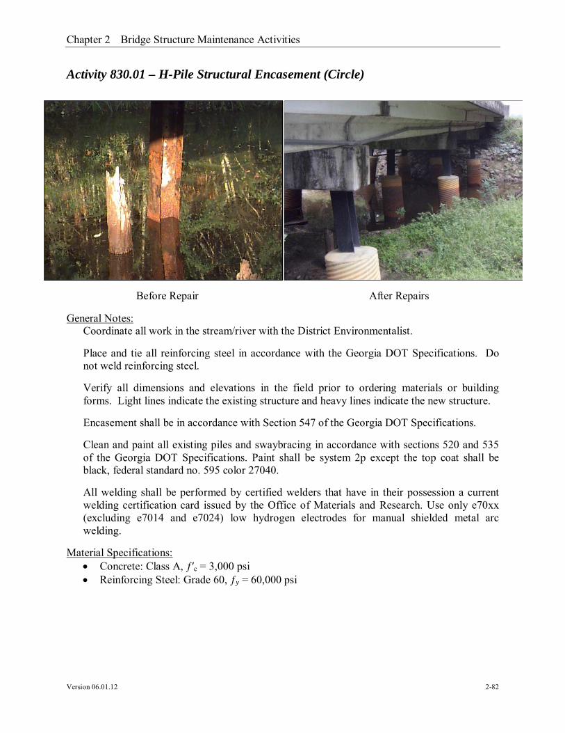
Activity 830.01 – H-Pile Structural Encasement (Circle)
General Notes:Coordinate all work in the stream/river with the District Environmentalist.
Place and tie all reinforcing steel in accordance with the Georgia DOT Specifications. Donot weld reinforcing steel.
Verify all dimensions and elevations in the field prior to ordering materials or buildingforms. Light lines indicate the existing structure and heavy lines indicate the new structure.
Encasement shall be in accordance with Section 547 of the Georgia DOT Specifications.
Clean and paint all existing piles and swaybracing in accordance with sections 520 and 535of the Georgia DOT Specifications. Paint shall be system 2p except the top coat shall beblack, federal standard no. 595 color 27040.
All welding shall be performed by certified welders that have in their possession a currentwelding certification card issued by the Office of Materials and Research. Use only e70xx(excluding e7014 and e7024) low hydrogen electrodes for manual shielded metal arcwelding.
Material Specifications: Concrete: Class A, ƒ′c = 3,000 psi Reinforcing Steel: Grade 60, ƒy = 60,000 psi
Before Repair After Repairs

Chapter 2 Bridge Structure Maintenance Activities
Version 06.01.12 2-83
Safety Traffic Control
o GDOT Operations Work Zone Traffic Control, oro GDOT Standard Drawings 9100 thru 9107 and MUTCD Part 6 – Temporary
Traffic Control Verify presence of lead paint system. Use special care near streams and rivers.
Georgia Standard Specifications Section 500 – Concrete Structures Section 501 – Steel Structures Section 511 – Reinforcement Steel Section 535 – Painting Structures
Georgia Special Provisions & Supplemental Specifications: None
Qualified Products List: QPL-10 List of Approved Concrete Plants QPL-12 Reinforcement Steel Fabricators QPL-18 Special Protective Coating QPL-19 Bar Supports QPL-56 Corrugated Metal Pipe


Chapter 2 Bridge Structure Maintenance Activities
Version 06.01.12 2-87
Activity 830.02 – H-Pile Structural Encasement (Square)
General Notes:Coordinate all work in the stream/river with the District Environmentalist.
Place and tie all reinforcing steel in accordance with the Georgia DOT Specifications. Donot weld reinforcing steel.
Verify all dimensions and elevations in the field prior to ordering materials or buildingforms. Light lines indicate the existing structure and heavy lines indicate the new structure.
Encasement shall be in accordance with section 547 of the Georgia DOT Specifications.
Clean and paint all existing piles and swaybracing in accordance with sections 520 and 535of the Georgia DOT Specifications. Paint shall be system 2p except the top coat shall beblack, federal standard no. 595 color 27040.
Material Specifications: Concrete: Class A, ƒ′c = 3,000 psi Reinforcing Steel: Grade 60, ƒy = 60,000 psi
Safety Traffic Control
o GDOT Operations Work Zone Traffic Control, oro GDOT Standard Drawings 9100 thru 9107 and MUTCD Part 6 – Temporary
Traffic Control Verify presence of lead paint system. Use special care near streams and rivers.
Before Repair After Repairs

Chapter 2 Bridge Structure Maintenance Activities
Version 06.01.12 2-88
Georgia Standard Specifications Section 500 – Concrete Structures Section 511 – Reinforcement Steel Section 520 - Piling Section 535 – Painting Structures
Georgia Special Provisions & Supplemental Specifications: None
Qualified Products List: QPL-10 List of Approved Concrete Plants QPL-12 Reinforcement Steel Fabricators QPL-18 Special Protective Coating


Chapter 2 Bridge Structure Maintenance Activities
Version 06.01.12 2-92
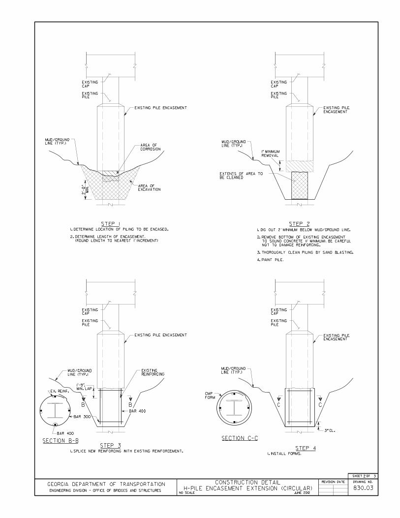
Activity 830.03 – H-Pile Encasement Extension (Circle)
General Notes:Coordinate all work in the stream/river with the District Environmentalist.
Place and tie all reinforcing steel in accordance with the Georgia DOT Specifications. Donot weld reinforcing steel.
Verify all dimensions and elevations in the field prior to ordering materials or buildingforms. Light lines indicate the existing structure and heavy lines indicate the new structure.
Encasement shall be in accordance with Section 547 of the Georgia DOT Specifications.
Clean and paint all existing piles and swaybracing in accordance with sections 520 and 535of the Georgia DOT Specifications. Paint shall be system 2p except the top coat shall beblack, federal standard no. 595 color 27040.
All welding shall be performed by certified welders that have in their possession a currentwelding certification card issued by the Office of Materials and Research. Use only e70xx(excluding e7014 and e7024) low hydrogen electrodes for manual shielded metal arcwelding.
Material Specifications: Concrete: Class A, ƒ′c = 3,000 psi Reinforcing Steel: Grade 60, ƒy = 60,000 psi
Before Repair After Repairs
Chapter 2 Bridge Structure Maintenance Activities
Version 06.01.12 2-93
Safety Traffic Control
o GDOT Operations Work Zone Traffic Control, oro GDOT Standard Drawings 9100 thru 9107 and MUTCD Part 6 – Temporary
Traffic Control Verify presence of lead paint system. Use special care near streams and rivers.
Georgia Standard Specifications Section 500 – Concrete Structures Section 501 – Steel Structures Section 511 – Reinforcement Steel Section 535 – Painting Structures
Georgia Special Provisions & Supplemental Specifications: None
Qualified Products List: QPL-10 List of Approved Concrete Plants QPL-12 Reinforcement Steel Fabricators QPL-18 Special Protective Coating QPL-19 Bar Supports QPL-56 Corrugated Metal Pipe


Chapter 2 Bridge Structure Maintenance Activities
Version 06.01.12 2-97
Activity 830.04 – H-Pile Encasement Extension (Square)
General Notes:Coordinate all work in the stream/river with the District Environmentalist.
Place and tie all reinforcing steel in accordance with the Georgia DOT Specifications. Donot weld reinforcing steel.
Verify all dimensions and elevations in the field prior to ordering materials or buildingforms. Light lines indicate the existing structure and heavy lines indicate the new structure.
Encasement shall be in accordance with section 547 of the Georgia DOT Specifications.
Clean and paint all existing piles and swaybracing in accordance with sections 520 and 535of the Georgia DOT Specifications. Paint shall be system 2p except the top coat shall beblack, federal standard no. 595 color 27040.
Material Specifications: Concrete: Class A, ƒ′c = 3,000 psi Reinforcing Steel: Grade 60, ƒy = 60,000 psi
Safety Traffic Control
o GDOT Operations Work Zone Traffic Control, oro GDOT Standard Drawings 9100 thru 9107 and MUTCD Part 6 – Temporary
Traffic Control Verify presence of lead paint system. Use special care near streams and rivers.
Before Repair After Repairs

Chapter 2 Bridge Structure Maintenance Activities
Version 06.01.12 2-98
Georgia Standard Specifications Section 500 – Concrete Structures Section 511 – Reinforcement Steel Section 520 - Piling Section 535 – Painting Structures
Georgia Special Provisions & Supplemental Specifications: None
Qualified Products List: QPL-10 List of Approved Concrete Plants QPL-12 Reinforcement Steel Fabricators QPL-18 Special Protective Coating


Chapter 2 Bridge Structure Maintenance Activities
Version 06.01.12 2-102
Activity 830.05 – H-Pile Plating Structural Repair-Bolt
General Notes:Coordinate all work in the stream/river with the District Environmentalist.
Verify all dimensions and elevations in the field prior to ordering materials or buildingforms. Light lines indicate the existing structure and heavy lines indicate the new structure.
Clean and paint piles and plating in accordance with Sections 520 and 535 of the GeorgiaDOT Specifications. Paint shall be System 2P except the top coat shall be black, federalstandard no. 595 color 27040.
Refer to Activity 830.03 – H-Pile Encasement (Circle) or 830.04 – H-Pile Encasement(Square), for additional details.
All bolts shall meet the requirements of ASTM A325 or ASTM A490.
Material Specifications: Structural Steel: Grade 50, ƒy = 50,000 psi
Safety Traffic Control
o GDOT Operations Work Zone Traffic Control, oro GDOT Standard Drawings 9100 thru 9107 and MUTCD Part 6 – Temporary
Traffic Control Verify presence of lead paint system. Use special care near streams and rivers.
Before Repair After Repairs
Chapter 2 Bridge Structure Maintenance Activities
Version 06.01.12 2-103
Georgia Standard Specifications Section 501 - Steel Structures Section 520 - Piling Section 535 - Painting Structures Section 852 – Miscellaneous Steel Material
Georgia Special Provisions & Supplemental Specifications: None
Qualified Products List: QPL-18 Special Protective Coating QPL-59 Miscellaneous Metal Fabricators


Chapter 2 Bridge Structure Maintenance Activities
Version 06.01.12 2-106
Activity 830.06 – H-Pile Plating Structural Repair-Weld
General Notes:Coordinate all work in the stream/river with the District Environmentalist. .
Verify all dimensions and elevations in the field prior to ordering materials or buildingforms. Light lines indicate the existing structure and heavy lines indicate the new structure.
All welding shall be performed by certified welders that have in their possession a currentwelding certification card issued by the Office of Materials and Research. Use only e70xx(excluding e7014 and e7024) low hydrogen electrodes for manual shielded metal arcwelding.
Clean and paint piles and plating in accordance with Sections 520 and 535 of the GeorgiaDOT Specifications. Paint shall be System 2P except the top coat shall be black, federalstandard no. 595 color 27040.
Refer to Activity 830.03 – H-Pile Encasement (Circle) or 830.04 – H-Pile Encasement(Square), for additional details.
Material Specifications: Structural Steel: Grade 50, ƒy = 50,000 psi
Safety Traffic Control
o GDOT Operations Work Zone Traffic Control, oro GDOT Standard Drawings 9100 thru 9107 and MUTCD Part 6 – Temporary
Traffic Control Verify presence of lead paint system. Use special care near streams and rivers.
Before Repair After Repairs
Chapter 2 Bridge Structure Maintenance Activities
Version 06.01.12 2-107
Georgia Standard Specifications Section 501 – Steel Structures Section 520 – Piling Section 535 – Painting Structures
Georgia Special Provisions & Supplemental Specifications: None
Qualified Products List: QPL-18 Special Protective Coating QPL-59 Miscellaneous Metal Fabricators


Chapter 2 Bridge Structure Maintenance Activities
Version 06.01.12 2-110
Activity 830.07 – H-Pile Swaybracing
General Notes:Coordinate all work in the stream/river with the District Environmentalist.
Verify all dimensions and elevations in the field prior to ordering materials or buildingforms. Light lines indicate the existing structure and heavy lines indicate the new structure.
Clean and paint all existing piles and swaybracing in accordance with sections 520 and 535of the Georgia DOT Specifications. Paint shall be system 2p except the top coat shall beblack, federal standard no. 595 color 27040.
All welding shall be performed by certified welders that have in their possession a currentwelding certification card issued by the Office of Materials and Research. Use only e70xx(excluding e7014 and e7024) low hydrogen electrodes for manual shielded metal arcwelding.
Material Specifications: Structural Steel: Grade 50, ƒy = 50,000 psi
Safety Traffic Control
o GDOT Operations Work Zone Traffic Control, oro GDOT Standard Drawings 9100 thru 9107 and MUTCD Part 6 – Temporary
Traffic Control Verify presence of lead paint system. Use special care near streams and rivers.
Before Repair After Repairs

Chapter 2 Bridge Structure Maintenance Activities
Version 06.01.12 2-111
Georgia Standard Specifications Section 501 – Steel Structures Section 520 - Piling Section 535 – Painting Structures
Georgia Special Provisions & Supplemental Specifications: None
Qualified Products List: QPL-18 Special Protective Coating QPL-59 Miscellaneous Metal Fabricators


Chapter 2 Bridge Structure Maintenance Activities
Version 06.01.12 2-114
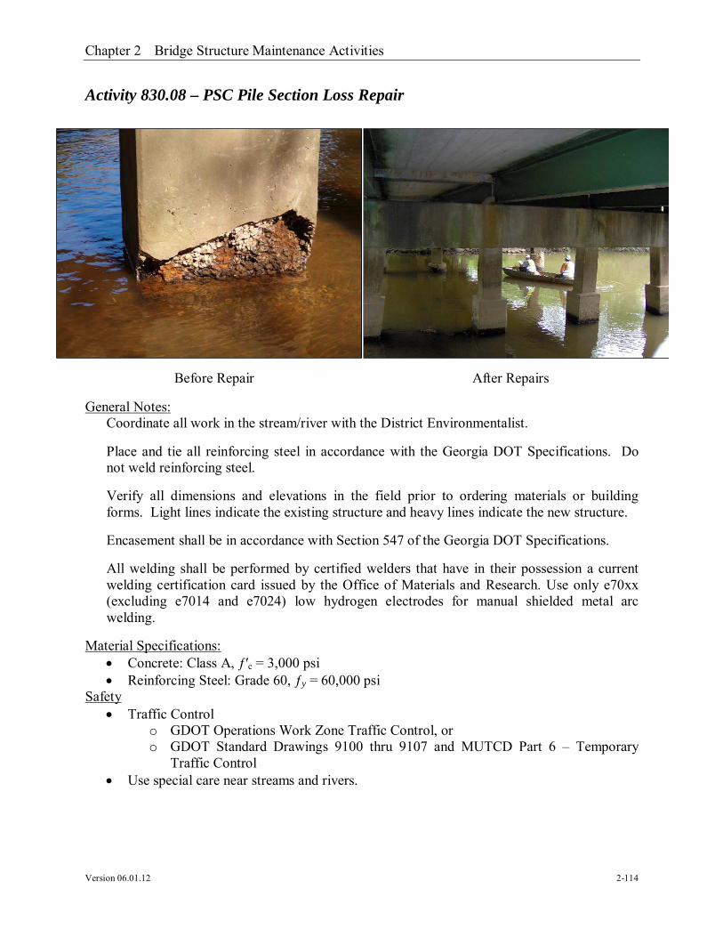
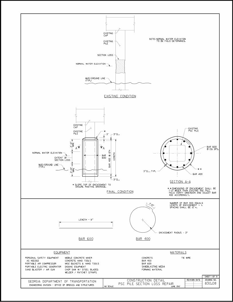
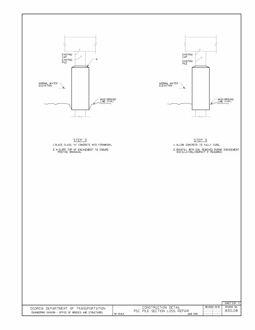
Activity 830.08 – PSC Pile Section Loss Repair
General Notes:Coordinate all work in the stream/river with the District Environmentalist.
Place and tie all reinforcing steel in accordance with the Georgia DOT Specifications. Donot weld reinforcing steel.
Verify all dimensions and elevations in the field prior to ordering materials or buildingforms. Light lines indicate the existing structure and heavy lines indicate the new structure.
Encasement shall be in accordance with Section 547 of the Georgia DOT Specifications.
All welding shall be performed by certified welders that have in their possession a currentwelding certification card issued by the Office of Materials and Research. Use only e70xx(excluding e7014 and e7024) low hydrogen electrodes for manual shielded metal arcwelding.
Material Specifications: Concrete: Class A, ƒ′c = 3,000 psi Reinforcing Steel: Grade 60, ƒy = 60,000 psi
Safety Traffic Control
o GDOT Operations Work Zone Traffic Control, oro GDOT Standard Drawings 9100 thru 9107 and MUTCD Part 6 – Temporary
Traffic Control Use special care near streams and rivers.
Before Repair After Repairs

Chapter 2 Bridge Structure Maintenance Activities
Version 06.01.12 2-115
Georgia Standard Specifications Section 500 – Concrete Structures Section 511 – Reinforcement Steel
Georgia Special Provisions & Supplemental Specifications: None
Qualified Products List: QPL-10 List of Approved Concrete Plants QPL-12 Reinforcement Steel Fabricators QPL-18 Special Protective Coating QPL-19 Bar Supports QPL-56 Corrugated Metal Pipe


Chapter 2 Bridge Structure Maintenance Activities
Version 06.01.12 2-119
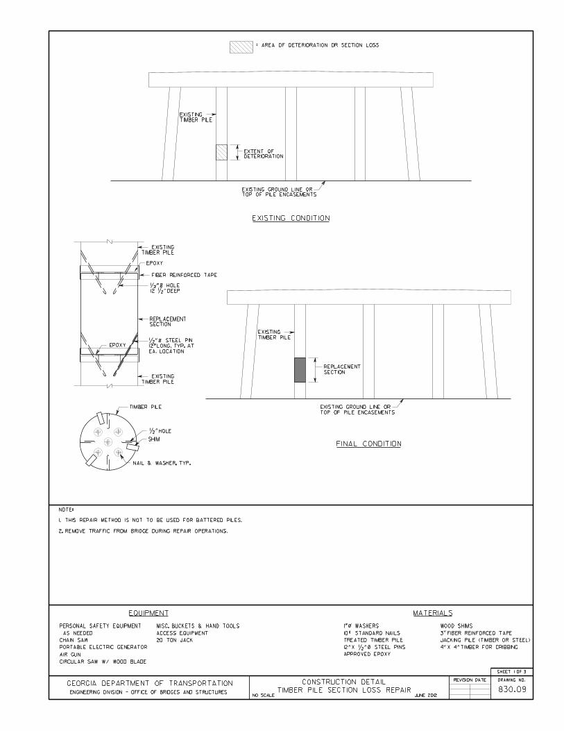
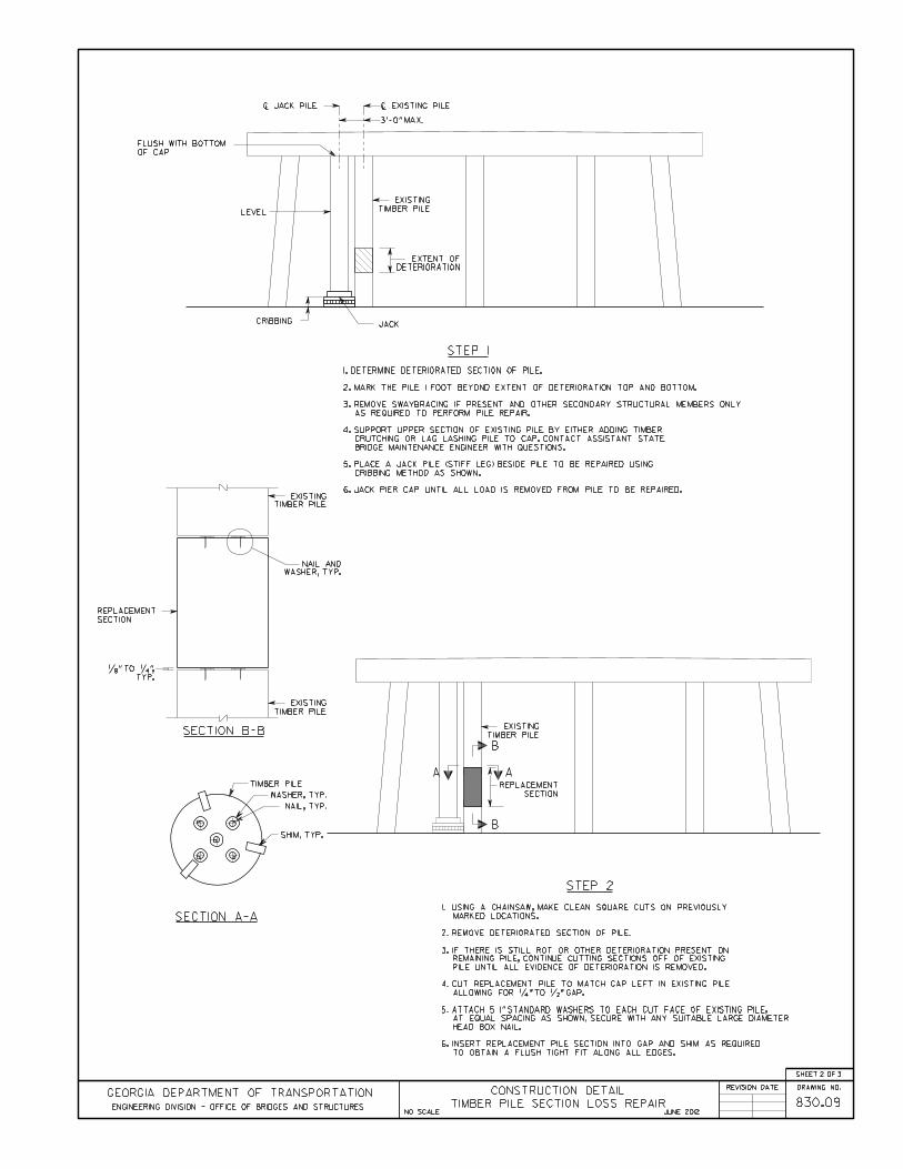
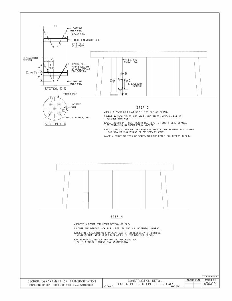
Activity 830.09 – Timber Pile Section Loss Repair
General Notes:Coordinate all work in the stream/river with the District Environmentalist.
Verify all dimensions and elevations in the field prior to ordering materials or buildingforms. Light lines indicate the existing structure and heavy lines indicate the new structure.
Material Specifications: None
Safety Traffic Control
o GDOT Operations Work Zone Traffic Control, oro GDOT Standard Drawings 9100 thru 9107 and MUTCD Part 6 – Temporary
Traffic Control Use special care near streams and rivers.
Georgia Standard Specifications Section 502 – Timber Structures Section 520 - Piling Section 860 – Lumber and Timber Section 861 – Piling and Round Tiber Section 861 – Preservative Treatment of Timber Products
Georgia Special Provisions & Supplemental Specifications: None
Before Repair After Repairs

Chapter 2 Bridge Structure Maintenance Activities
Version 06.01.12 2-120
Qualified Products List: QPL-50 Wood Preserving Plants

Chapter 2 Bridge Structure Maintenance Activities
Version 06.01.12 2-124
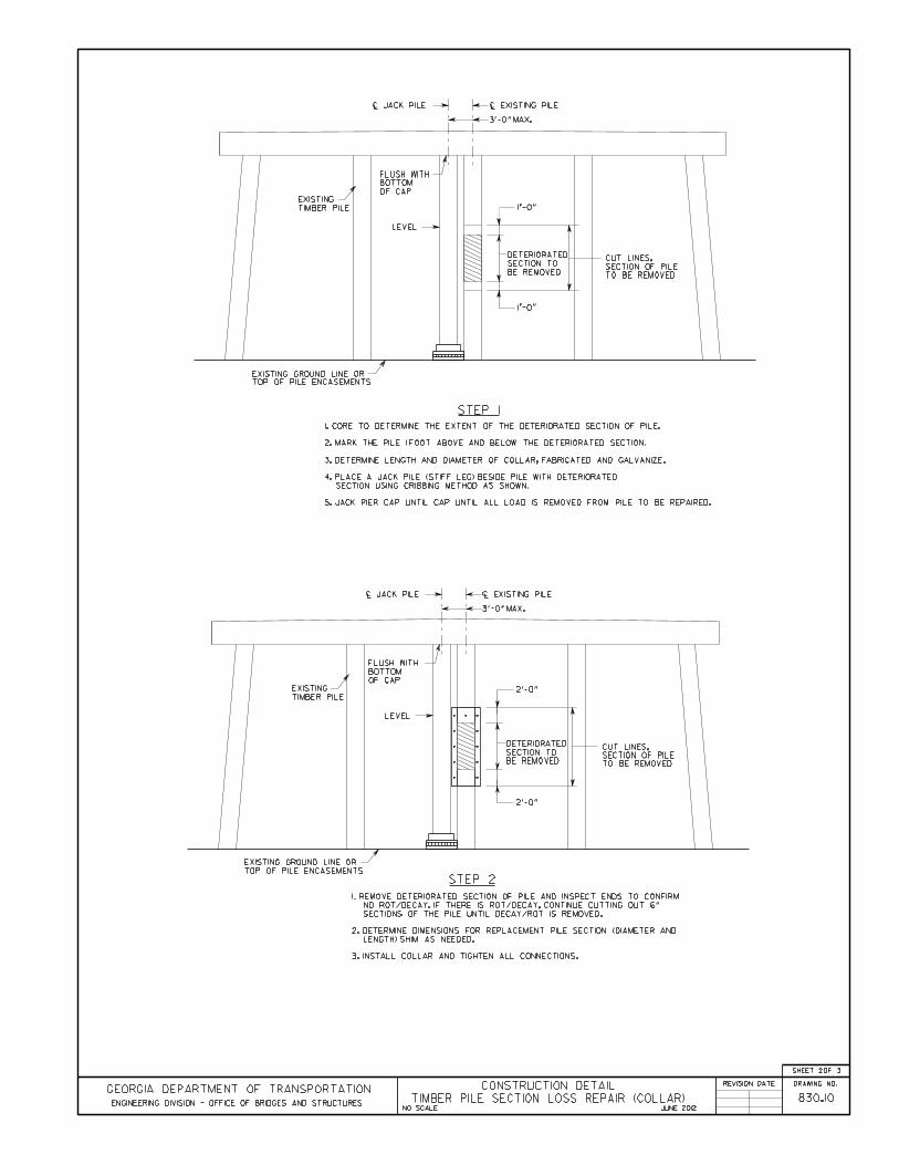
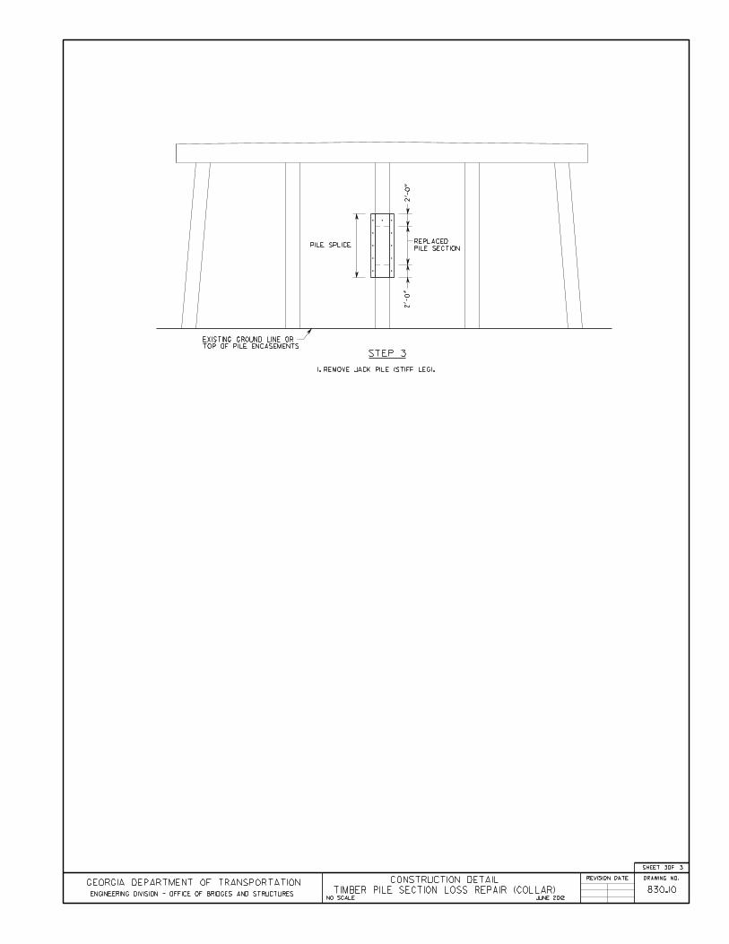
Activity 830.10 – Timber Pile Section Loss Repair (Collar)
General Notes:Verify all dimensions and elevations in the field prior to ordering materials or buildingforms. Light lines indicate the existing structure and heavy lines indicate the new structure.
All bolts shall meet the requirements of ASTM A325 or ASTM A490.
All steel components shall be galvanized in accordance with ASTM A123.
Material Specifications: Structural Steel: Grade 36, ƒy = 36,000 psi
Safety Traffic Control
o GDOT Operations Work Zone Traffic Control, oro GDOT Standard Drawings 9100 thru 9107 and MUTCD Part 6 – Temporary
Traffic Control Use special care near streams and rivers.
Georgia Standard Specifications Section 501 – Steel Structures Section 502 – Timber Structures Section 520 – Piling Section 860 – Lumber and Timber Section 861 – Piling and Round Tiber Section 861 – Preservative Treatment of Timber Products
Before Repair After Repairs

Chapter 2 Bridge Structure Maintenance Activities
Version 06.01.12 2-125
Georgia Special Provisions & Supplemental Specifications: None
Qualified Products List: QPL-50 Wood Preserving Plants QPL-53 Galvanizers QPL-59 Miscellaneous Metal Fabricators

Chapter 2 Bridge Structure Maintenance Activities
Version 06.01.12 2-129
Activity 830.11 – Timber Pile Section Loss Repair (Encasement)
General Notes:Timber Pile Encasement is to be used only as a temporary repair and not shall exceed fiveyears of service.
Coordinate all work in the stream/river with the District Environmentalist.
Place and tie all reinforcing steel in accordance with the Georgia DOT Specifications. Donot weld reinforcing steel.
Verify all dimensions and elevations in the field prior to ordering materials or buildingforms. Light lines indicate the existing structure and heavy lines indicate the new structure.
Encasement shall be in accordance with Section 547 of the Georgia DOT Specifications.
All welding shall be performed by certified welders that have in their possession a currentwelding certification card issued by the Office of Materials and Research. Use only e70xx(excluding e7014 and e7024) low hydrogen electrodes for manual shielded metal arcwelding.
Material Specifications: Concrete: Class A, ƒ′c = 3,000 psi Reinforcing Steel: Grade 60, ƒy = 60,000 psi
Safety Traffic Control
o GDOT Operations Work Zone Traffic Control, oro GDOT Standard Drawings 9100 thru 9107 and MUTCD Part 6 – Temporary
Traffic Control Use special care near streams and rivers.
Before Repair After Repairs

Chapter 2 Bridge Structure Maintenance Activities
Version 06.01.12 2-130
Georgia Standard Specifications Section 500 – Concrete Structures Section 511 – Reinforcement Steel
Georgia Special Provisions & Supplemental Specifications: None
Qualified Products List: QPL-10 List of Approved Concrete Plants QPL-12 Reinforcement Steel Fabricators QPL-18 Special Protective Coating QPL-19 Bar Supports QPL-56 Corrugated Metal Pipe
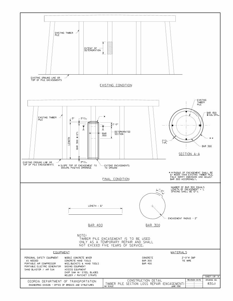

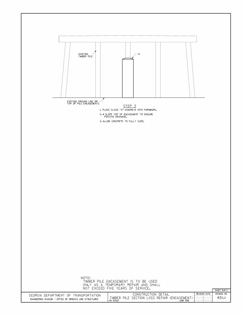
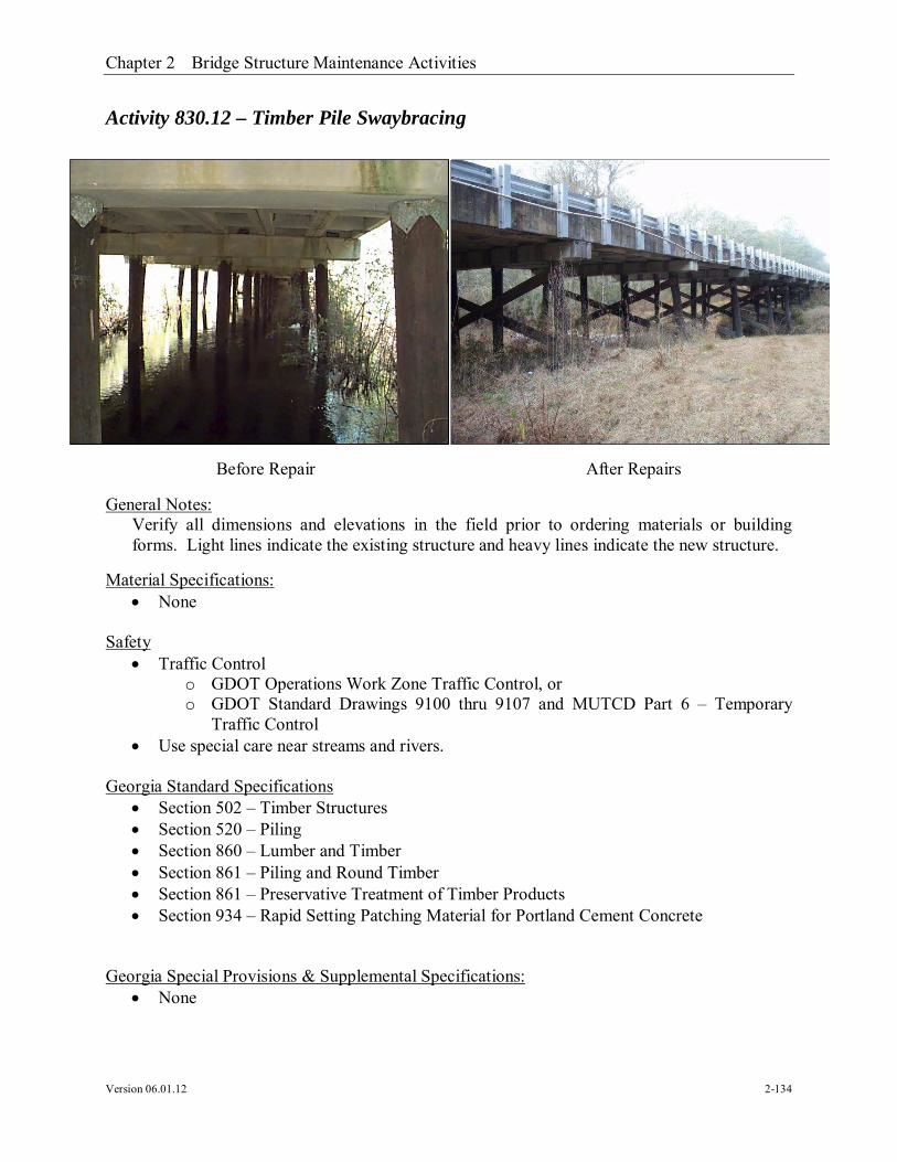
Chapter 2 Bridge Structure Maintenance Activities
Version 06.01.12 2-134
Activity 830.12 – Timber Pile Swaybracing
General Notes:Verify all dimensions and elevations in the field prior to ordering materials or buildingforms. Light lines indicate the existing structure and heavy lines indicate the new structure.
Material Specifications: None
Safety Traffic Control
o GDOT Operations Work Zone Traffic Control, oro GDOT Standard Drawings 9100 thru 9107 and MUTCD Part 6 – Temporary
Traffic Control Use special care near streams and rivers.
Georgia Standard Specifications Section 502 – Timber Structures Section 520 – Piling Section 860 – Lumber and Timber Section 861 – Piling and Round Timber Section 861 – Preservative Treatment of Timber Products Section 934 – Rapid Setting Patching Material for Portland Cement Concrete
Georgia Special Provisions & Supplemental Specifications: None
Before Repair After Repairs
Chapter 2 Bridge Structure Maintenance Activities
Version 06.01.12 2-135
Qualified Products List: QPL-50 Wood Preserving Plants
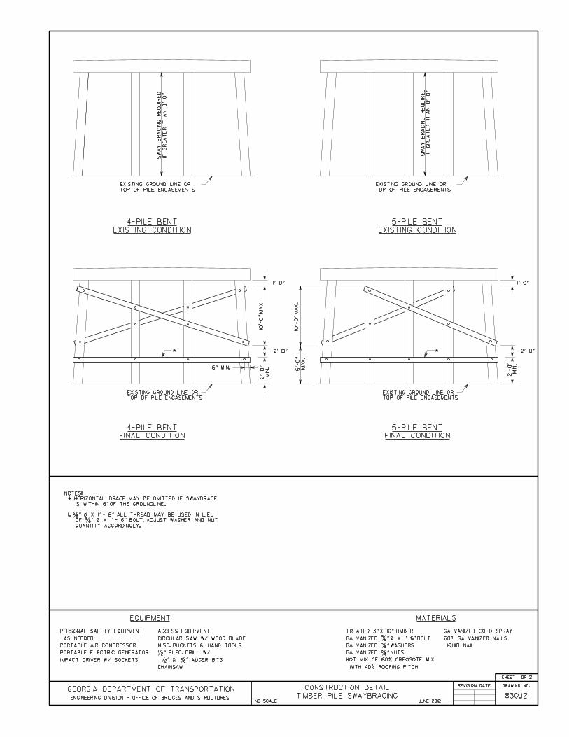
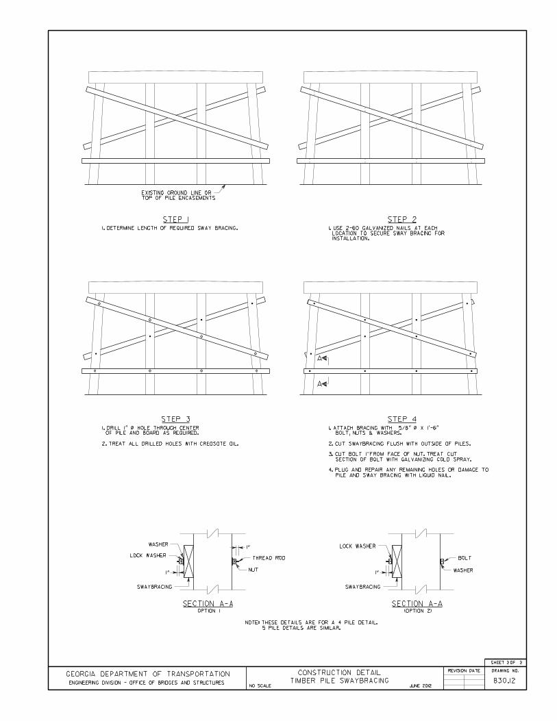

Chapter 2 Bridge Structure Maintenance Activities
Version 06.01.12 2-138
Activity 830.13 – Epoxy Injection (Cap and Columns)
General Notes:Verify all dimensions and elevations in the field prior to ordering materials or buildingforms. Light lines indicate the existing structure and heavy lines indicate the new structure.
Material Specifications: None
Safety Traffic Control
o GDOT Operations Work Zone Traffic Control, oro GDOT Standard Drawings 9100 thru 9107 and MUTCD Part 6 – Temporary
Traffic Control
Georgia Standard Specifications Section 528 – Epoxy Pressure Injection of Cracks
Georgia Special Provisions & Supplemental Specifications: Section 528 – Epoxy Pressure Injection of Concrete Cracks
Qualified Products List: None
Before Repair After Repairs


Chapter 2 Bridge Structure Maintenance Activities
Version 06.01.12 2-141
Activity 830.14 – Cap-Column Spall Repair – Full Depth
General Notes:Verify all dimensions and elevations in the field prior to ordering materials or buildingforms. Light lines indicate the existing structure and heavy lines indicate the new structure.
Apply epoxy resin adhesive Type II to all hardened concrete surfaces just prior to pouring theconcrete, see section 886 of the Georgia DOT Specifications.
Thoroughly clean existing reinforcement of concrete scale and rust by sand blasting beforebonding into new construction.
Material Specifications: Concrete: Class AA, ƒ′c = 3,500 psi
Safety Traffic Control
o GDOT Operations Work Zone Traffic Control, oro GDOT Standard Drawings 9100 thru 9107 and MUTCD Part 6 – Temporary
Traffic Control
Georgia Standard Specifications Section 500 – Concrete Structures Section 504 – Twenty-Four Hour Accelerated Strength Concrete Section 886 – Epoxy Resin Adhesive Section 934 – Rapid Setting Patching Material for Portland Cement Concrete
Georgia Special Provisions & Supplemental Specifications: Section 521 – Patching Concrete Bridge
Before Repair After Repairs

Chapter 2 Bridge Structure Maintenance Activities
Version 06.01.12 2-142
Qualified Products List: QPL-10 List of Approved Concrete Plants QPL-15 Epoxy Resin Adhesives QPL-27 Rapid Setting Patching Material


Chapter 2 Bridge Structure Maintenance Activities
Version 06.01.12 2-145
Activity 830.15 – Cap-Column Spall Repair – Surface
General Notes:Verify all dimensions and elevations in the field prior to ordering materials or buildingforms. Light lines indicate the existing structure and heavy lines indicate the new structure.
Apply epoxy resin adhesive Type II to all hardened concrete surfaces just prior to pouring theconcrete, see section 886 of the Georgia DOT Specifications.
Thoroughly clean existing reinforcement of concrete scale and rust by sand blasting beforebonding into new construction.
Material Specifications: Concrete: Class AA, ƒ′c = 3,500 psi
Safety Traffic Control
o GDOT Operations Work Zone Traffic Control, oro GDOT Standard Drawings 9100 thru 9107 and MUTCD Part 6 – Temporary
Traffic Control
Georgia Standard Specifications Section 500 – Concrete Structures Section 504 – Twenty-Four Hour Accelerated Strength Concrete Section 886 – Epoxy Resin Adhesive Section 934 – Rapid Setting Patching Material for Portland Cement Concrete
Georgia Special Provisions & Supplemental Specifications: Section 521 – Patching Concrete Bridge
Before Repair After Repairs

Chapter 2 Bridge Structure Maintenance Activities
Version 06.01.12 2-146
Qualified Products List: QPL-10 List of Approved Concrete Plants QPL-15 Epoxy Resin Adhesives QPL-27 Rapid Setting Patching Material


Chapter 2 Bridge Structure Maintenance Activities
Version 06.01.12 2-149
Activity 830.16 - Cap Extension - Widening
General Notes:Place and tie all reinforcing steel in accordance with the Georgia DOT Specifications. Donot weld reinforcing steel.
Verify all dimensions and elevations in the field prior to ordering materials or buildingforms. Light lines indicate the existing structure and heavy lines indicate the new structure.
Apply epoxy resin adhesive Type II to all hardened concrete surfaces just prior to pouring theconcrete, see section 886 of the Georgia DOT Specifications.
Material Specifications: Concrete: Class A, ƒ′c = 3,000 psi Reinforcing Steel: Grade 60, ƒy = 60,000 psi
Safety Traffic Control
o GDOT Operations Work Zone Traffic Control, oro GDOT Standard Drawings 9100 thru 9107 and MUTCD Part 6 – Temporary
Traffic Control Use special care near streams and rivers.
Georgia Standard Specifications Section 500 – Concrete Structures Section 511 – Reinforcement Steel
Georgia Special Provisions & Supplemental Specifications: None
Before Repair After Repairs

Chapter 2 Bridge Structure Maintenance Activities
Version 06.01.12 2-150
Qualified Products List: QPL-10 List of Approved Concrete Plants QPL-12 Reinforcement Steel Fabricators QPL-15 Epoxy Resin Adhesives
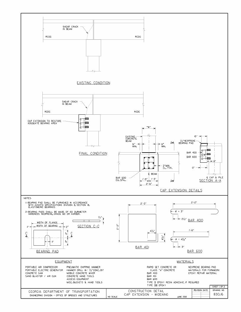

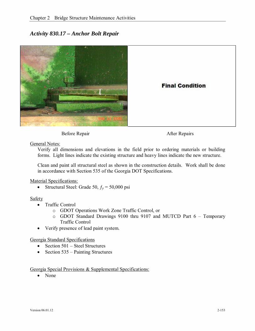
Chapter 2 Bridge Structure Maintenance Activities
Version 06.01.12 2-153
Activity 830.17 – Anchor Bolt Repair
General Notes:Verify all dimensions and elevations in the field prior to ordering materials or buildingforms. Light lines indicate the existing structure and heavy lines indicate the new structure.
Clean and paint all structural steel as shown in the construction details. Work shall be donein accordance with Section 535 of the Georgia DOT Specifications.
Material Specifications: Structural Steel: Grade 50, ƒy = 50,000 psi
Safety Traffic Control
o GDOT Operations Work Zone Traffic Control, oro GDOT Standard Drawings 9100 thru 9107 and MUTCD Part 6 – Temporary
Traffic Control Verify presence of lead paint system.
Georgia Standard Specifications Section 501 – Steel Structures Section 535 – Painting Structures
Georgia Special Provisions & Supplemental Specifications: None
Before Repair After Repairs

Chapter 2 Bridge Structure Maintenance Activities
Version 06.01.12 2-154
Qualified Products List: QPL-59 Miscellaneous Metal Fabricators QPL-73 Bridge Paint Systems


Chapter 2 Bridge Structure Maintenance Activities
Version 06.01.12 2-157
Activity 830.18 – Endwall Spalls – Full Depth
General Notes:Verify all dimensions and elevations in the field prior to ordering materials or buildingforms. Light lines indicate the existing structure and heavy lines indicate the new structure.
Apply epoxy resin adhesive Type II to all hardened concrete surfaces just prior to pouring theconcrete, see section 886 of the Georgia DOT Specifications.
Material Specifications: Concrete: Class AA, ƒ′c = 3,500 psi
Safety Traffic Control
o GDOT Operations Work Zone Traffic Control, oro GDOT Standard Drawings 9100 thru 9107 and MUTCD Part 6 – Temporary
Traffic Control
Georgia Standard Specifications Section 500 – Concrete Structures Section 886 – Epoxy Resin Adhesive Section 934 – Rapid Setting Patching Material for Portland Cement Concrete
Georgia Special Provisions & Supplemental Specifications: Section 521 – Patching Concrete Bridge
Before Repair After Repairs

Chapter 2 Bridge Structure Maintenance Activities
Version 06.01.12 2-158
Qualified Products List: QPL-10 List of Approved Concrete Plants QPL-15 Epoxy Resin Adhesives QPL-27 Rapid Setting Patching Material
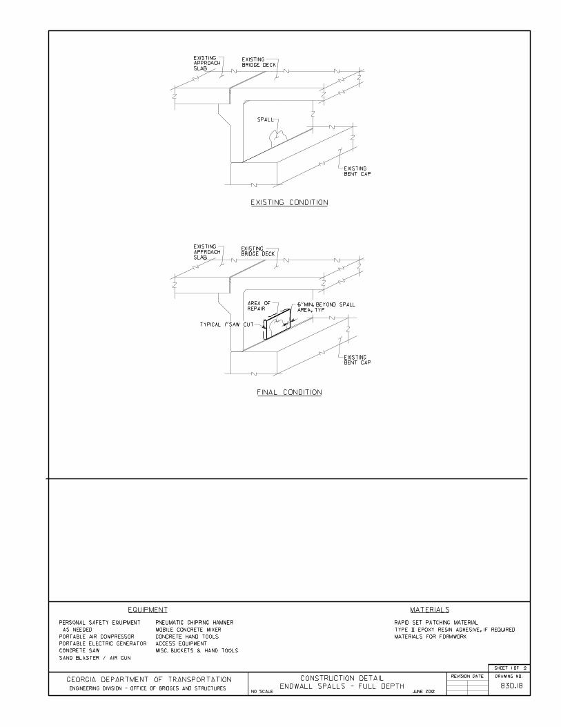


Chapter 2 Bridge Structure Maintenance Activities
Version 06.01.12 2-161
Activity 830.19 – Endwall Spalls – Surface
General Notes:Verify all dimensions and elevations in the field prior to ordering materials or buildingforms. Light lines indicate the existing structure and heavy lines indicate the new structure.
Apply epoxy resin adhesive Type II to all hardened concrete surfaces just prior to pouring theconcrete, see section 886 of the Georgia DOT Specifications.
Material Specifications: Concrete: Class AA, ƒ′c = 3,500 psi
Safety Traffic Control
o GDOT Operations Work Zone Traffic Control, oro GDOT Standard Drawings 9100 thru 9107 and MUTCD Part 6 – Temporary
Traffic Control
Georgia Standard Specifications Section 500 – Concrete Structures Section 886 – Epoxy Resin Adhesive Section 934 – Rapid Setting Patching Material for Portland Cement Concrete
Department of Transportation State of Georgia Special Provisions & SupplementalSpecifications:
Section 521 – Patching Concrete Bridge
Before Repair After Repairs

Chapter 2 Bridge Structure Maintenance Activities
Version 06.01.12 2-162
Qualified Products List: QPL-10 List of Approved Concrete Plants QPL-15 Epoxy Resin Adhesives QPL-27 Rapid Setting Patching Material

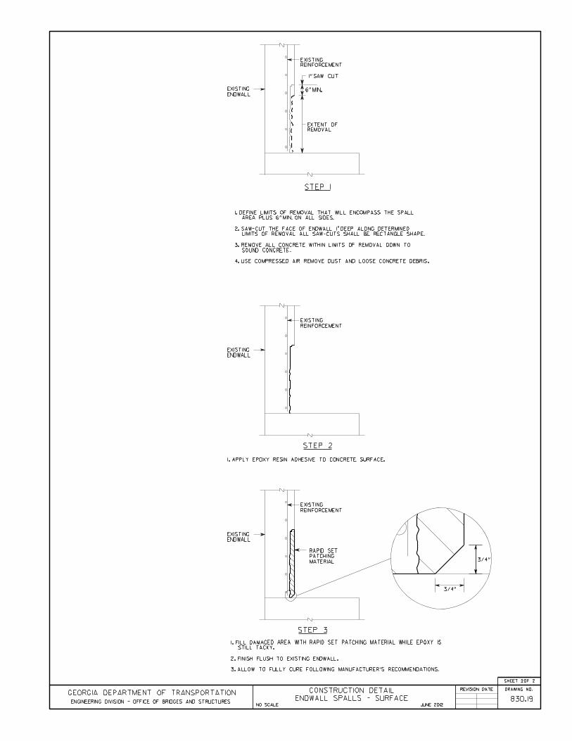

Chapter 2 Bridge Structure Maintenance Activities
Version 06.01.12 2-165
Activity 830.20 – Beam Web Section Loss Repair
General Notes:Verify all dimensions and elevations in the field prior to ordering materials or buildingforms. Light lines indicate the existing structure and heavy lines indicate the new structure.
All welding shall be performed by certified welders that have in their possession a currentwelding certification card issued by the Office of Materials and Research. Use only e70xx(excluding e7014 and e7024) low hydrogen electrodes for manual shielded metal arcwelding.
Clean and paint all structural steel as shown in the construction details. Work shall be donein accordance with Section 535 of the Georgia DOT Specifications.
Do not use this detail for weathering steel.
Material Specifications: Structural Steel: Grade 50, ƒy = 50,000 psi
Safety Traffic Control
o GDOT Operations Work Zone Traffic Control, oro GDOT Standard Drawings 9100 thru 9107 and MUTCD Part 6 – Temporary
Traffic Control Verify presence of lead paint system.
Georgia Standard Specifications Section 501 – Steel Structures Section 535 – Painting Structures
Before Repair After Repairs

Chapter 2 Bridge Structure Maintenance Activities
Version 06.01.12 2-166
Georgia Special Provisions & Supplemental Specifications: None
Qualified Products List: QPL-59 Miscellaneous Metal Fabricators QPL-73 Bridge Paint Systems


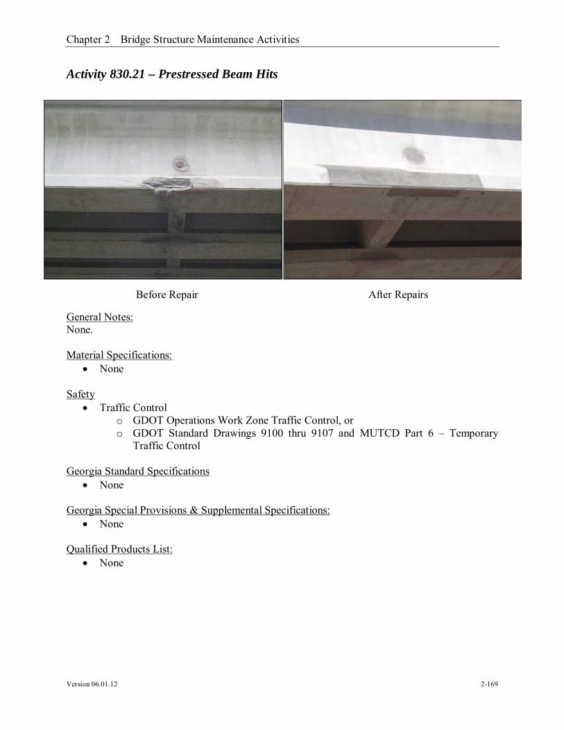
Chapter 2 Bridge Structure Maintenance Activities
Version 06.01.12 2-169
Activity 830.21 – Prestressed Beam Hits
General Notes:None.
Material Specifications: None
Safety Traffic Control
o GDOT Operations Work Zone Traffic Control, oro GDOT Standard Drawings 9100 thru 9107 and MUTCD Part 6 – Temporary
Traffic Control
Georgia Standard Specifications None
Georgia Special Provisions & Supplemental Specifications: None
Qualified Products List: None
Before Repair After Repairs


Chapter 2 Bridge Structure Maintenance Activities
Version 06.01.12 2-171
Activity 830.22 – Spall Repair of RCDG
General Notes:Verify all dimensions and elevations in the field prior to ordering materials or buildingforms. Light lines indicate the existing structure and heavy lines indicate the new structure.
Apply epoxy resin adhesive Type II to all hardened concrete surfaces just prior to pouring theconcrete, see section 886 of the Georgia DOT Specifications.
Thoroughly clean existing reinforcement of concrete scale and rust by sand blasting beforebonding into new construction.
Material Specifications: Concrete: Class AA, ƒ′c = 3,500 psi
Safety Traffic Control
o GDOT Operations Work Zone Traffic Control, oro GDOT Standard Drawings 9100 thru 9107 and MUTCD Part 6 – Temporary
Traffic Control
Georgia Standard Specifications Section 500 – Concrete Structures Section 504 – Twenty-Four Hour Accelerated Strength Concrete Section 886 – Epoxy Resin Adhesive Section 934 – Rapid Setting Patching Material for Portland Cement Concrete
Georgia Special Provisions & Supplemental Specifications: Section 521 – Patching Concrete Bridge
Before Repair After Repairs

Chapter 2 Bridge Structure Maintenance Activities
Version 06.01.12 2-172
Qualified Products List: QPL-10 List of Approved Concrete Plants QPL-15 Epoxy Resin Adhesives QPL-27 Rapid Setting Patching Material


Chapter 2 Bridge Structure Maintenance Activities
Version 06.01.12 2-175
Activity 830.23 – Bearing Failure Repair Under RCDG
General Notes:Verify all dimensions and elevations in the field prior to ordering materials or buildingforms. Light lines indicate the existing structure and heavy lines indicate the new structure.
Material Specifications: None
Safety Traffic Control
o GDOT Operations Work Zone Traffic Control, oro GDOT Standard Drawings 9100 thru 9107 and MUTCD Part 6 – Temporary
Traffic Control
Georgia Standard Specifications Section 500 – Concrete Structures Section 885 – Elastomeric Bearing Pads Section 886 – Epoxy Resin Adhesive
Georgia Special Provisions & Supplemental Specifications: None
Qualified Products List: None
Before Repair After Repairs


Chapter 2 Bridge Structure Maintenance Activities
Version 06.01.12 2-178
Activity 830.24 – Edge Beam Replacement
General Notes:Place and tie all reinforcing steel in accordance with the Georgia DOT Specifications. Donot weld reinforcing steel.
Verify all dimensions and elevations in the field prior to ordering materials or buildingforms. Light lines indicate the existing structure and heavy lines indicate the new structure.
Apply epoxy resin adhesive Type II to all hardened concrete surfaces just prior to pouring theconcrete, see section 886 of the Georgia DOT Specifications.
Bend existing reinforcement to be utilized in new construction in a manner to provide themaximum lap possible or as shown on the plans. Thoroughly clean existing reinforcement ofconcrete scale and rust by sand blasting before bonding into new construction.
All welding shall be performed by certified welders that have in their possession a currentwelding certification card issued by the Office of Materials and Research. Use only e70xx(excluding e7014 and e7024) low hydrogen electrodes for manual shielded metal arcwelding.
Clean and paint all structural steel as shown in the construction details. Work shall be donein accordance with Section 535 of the Georgia DOT Specifications.
Material Specifications: Concrete: Class AA, ƒ′c = 3,500 psi Reinforcing Steel: Grade 60, ƒy = 60,000 psi
Before Repair After Repairs

Chapter 2 Bridge Structure Maintenance Activities
Version 06.01.12 2-179
Safety Traffic Control
o GDOT Operations Work Zone Traffic Control, oro GDOT Standard Drawings 9100 thru 9107 and MUTCD Part 6 – Temporary
Traffic Control Verify presence of lead paint system. Use special care near streams and rivers.
Georgia Standard Specifications Section 500 – Concrete Structures Section 504 – Twenty-Four Hour Accelerated Strength Concrete Section 511 – Reinforcement Steel Section 535 – Painting Structures Section 886 – Epoxy Resin Adhesive
Georgia Special Provisions & Supplemental Specifications: None
Qualified Products List: QPL-10 List of Approved Concrete Plants QPL-12 Reinforcement Steel Fabricators QPL-15 Epoxy Resin Adhesives QPL-73 Bridge Paint Systems


Chapter 2 Bridge Structure Maintenance Activities
Version 06.01.12 2-183
Activity 830.25 – Staged Edge Beam Replacement
General Notes:Place and tie all reinforcing steel in accordance with the Georgia DOT Specifications. Donot weld reinforcing steel.
Verify all dimensions and elevations in the field prior to ordering materials or buildingforms. Light lines indicate the existing structure and heavy lines indicate the new structure.
Apply epoxy resin adhesive Type II to all hardened concrete surfaces just prior to pouring theconcrete, see section 886 of the Georgia DOT Specifications.
Bend existing reinforcement to be utilized in new construction in a manner to provide themaximum lap possible or as shown on the plans. Thoroughly clean existing reinforcement ofconcrete scale and rust by sand blasting before bonding into new construction.
All welding shall be performed by certified welders that have in their possession a currentwelding certification card issued by the Office of Materials and Research. Use only e70xx(excluding e7014 and e7024) low hydrogen electrodes for manual shielded metal arcwelding.
Clean and paint all structural steel as shown in the construction details. Work shall be donein accordance with Section 535 of the Georgia DOT Specifications.
Material Specifications: Concrete: Class AA, ƒ′c = 3,500 psi Reinforcing Steel: Grade 60, ƒy = 60,000 psi
Before Repair After Repairs
Chapter 2 Bridge Structure Maintenance Activities
Version 06.01.12 2-184
Safety Traffic Control
o GDOT Operations Work Zone Traffic Control, oro GDOT Standard Drawings 9100 thru 9107 and MUTCD Part 6 – Temporary
Traffic Control Verify presence of lead paint system. Use special care near streams and rivers.
Georgia Standard Specifications Section 500 – Concrete Structures Section 504 – Twenty-Four Hour Accelerated Strength Concrete Section 511 – Reinforcement Steel Section 535 – Painting Structures Section 886 – Epoxy Resin Adhesive
Georgia Special Provisions & Supplemental Specifications: None
Qualified Products List: QPL-10 List of Approved Concrete Plants QPL-12 Reinforcement Steel Fabricators QPL-15 Epoxy Resin Adhesives QPL-73 Bridge Paint Systems
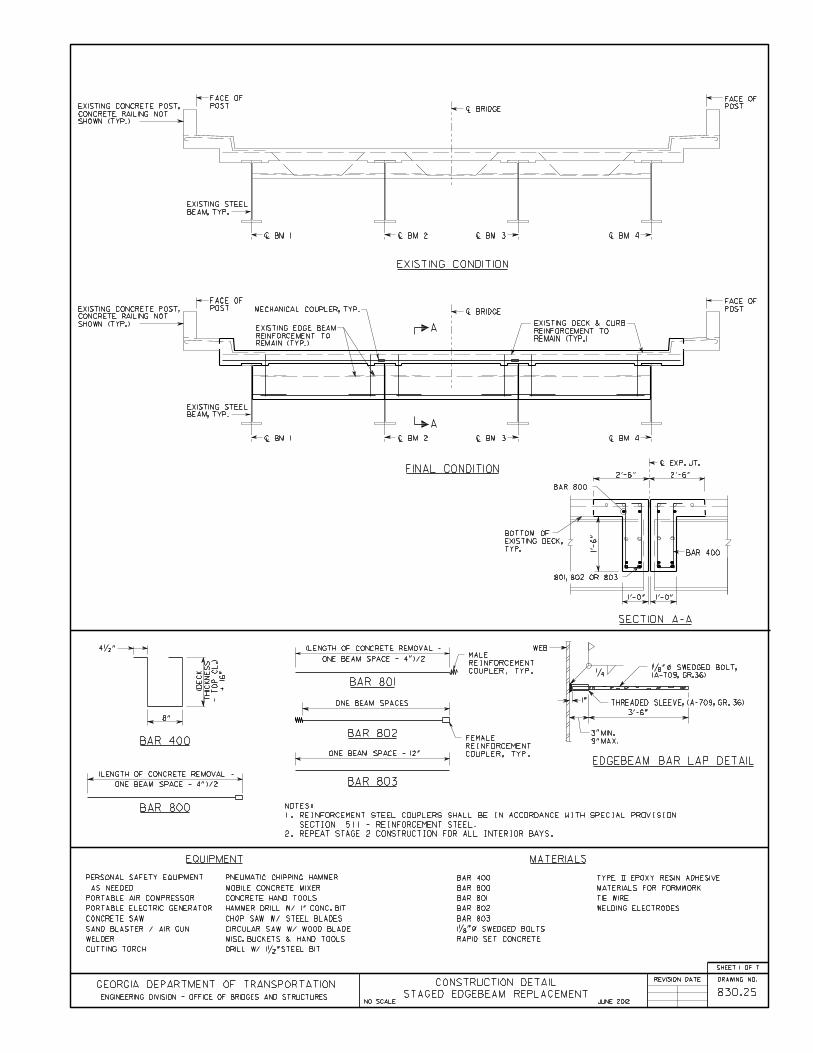
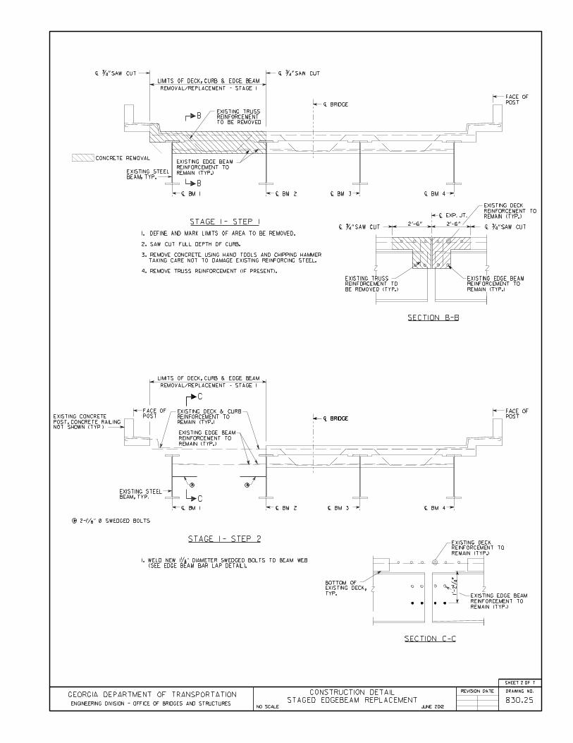


Chapter 2 Bridge Structure Maintenance Activities
Version 06.01.12 2-192
Activity 845.01 – Rip Rap Placement
General Notes:Verify all dimensions and elevations in the field prior to ordering material.
Material Specifications: None
Safety Traffic Control
o GDOT Operations Work Zone Traffic Control, oro GDOT Standard Drawings 9100 thru 9107 and MUTCD Part 6 – Temporary
Traffic Control Use special care near streams and rivers.
Georgia Standard Specifications: Section 603 – Rip Rap Section 805 – Rip Rap and Curbing Stone Section 881 – Fabrics
Georgia Special Provisions & Supplemental Specifications: None
Qualified Products List: QPL-28 Filter Fabric
Before Repair After Repairs


Chapter 2 Bridge Structure Maintenance Activities
Version 06.01.12 2-195
Activity 845.02 – Erosion Repair at Abutments
General Notes:Verify all dimensions and elevations in the field prior to ordering materials or buildingforms.
Material Specifications: Concrete: Class B, ƒ′c = 2,200 psi
Safety Traffic Control
o GDOT Operations Work Zone Traffic Control, oro GDOT Standard Drawings 9100 thru 9107 and MUTCD Part 6 – Temporary
Traffic Control
Georgia Standard Specifications Section 600 – Controlled Low Strength Flowable Fill Section 603 – Rip Rap
Georgia Special Provisions & Supplemental Specifications: None
Qualified Products List: QPL-28 Filter Fabric
Before Repair After Repairs


Chapter 2 Bridge Structure Maintenance Activities
Version 06.01.12 2-198
Activity 845.03 – Pile Bent Scour Repair
General Notes:Verify all dimensions and elevations in the field prior to ordering material.
Material Specifications: None
Safety Traffic Control
o GDOT Operations Work Zone Traffic Control, oro GDOT Standard Drawings 9100 thru 9107 and MUTCD Part 6 – Temporary
Traffic Control Use special care near streams and rivers.
Georgia Standard Specifications Section 211 – Bridge Excavation and Backfill Section 603 – Rip Rap Section 805 – Rip Rap and Curbing Stone Section 810 – Roadway Section 812 – Backfill Materials Section 881 – Fabrics
Georgia Special Provisions & Supplemental Specifications: None
Qualified Products List: None
Before Repair After Repairs
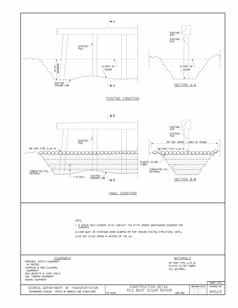


Chapter 2 Bridge Structure Maintenance Activities
Version 06.01.12 2-201
Activity 845.04 – Slope Paving Repair
General Notes:Verify all dimensions and elevations in the field prior to ordering materials or buildingforms. Light lines indicate the existing structure and heavy lines indicate the new structure.
Material Specifications: Concrete: Class B, ƒ′c = 2,200 psi
Safety Traffic Control
o GDOT Operations Work Zone Traffic Control, oro GDOT Standard Drawings 9100 thru 9107 and MUTCD Part 6 – Temporary
Traffic Control
Georgia Standard Specifications Section 441 – Miscellaneous Concrete Section 812 – Backfill Material
Georgia Special Provisions & Supplemental Specifications: None
Qualified Products List: None
Before Repair After Repairs

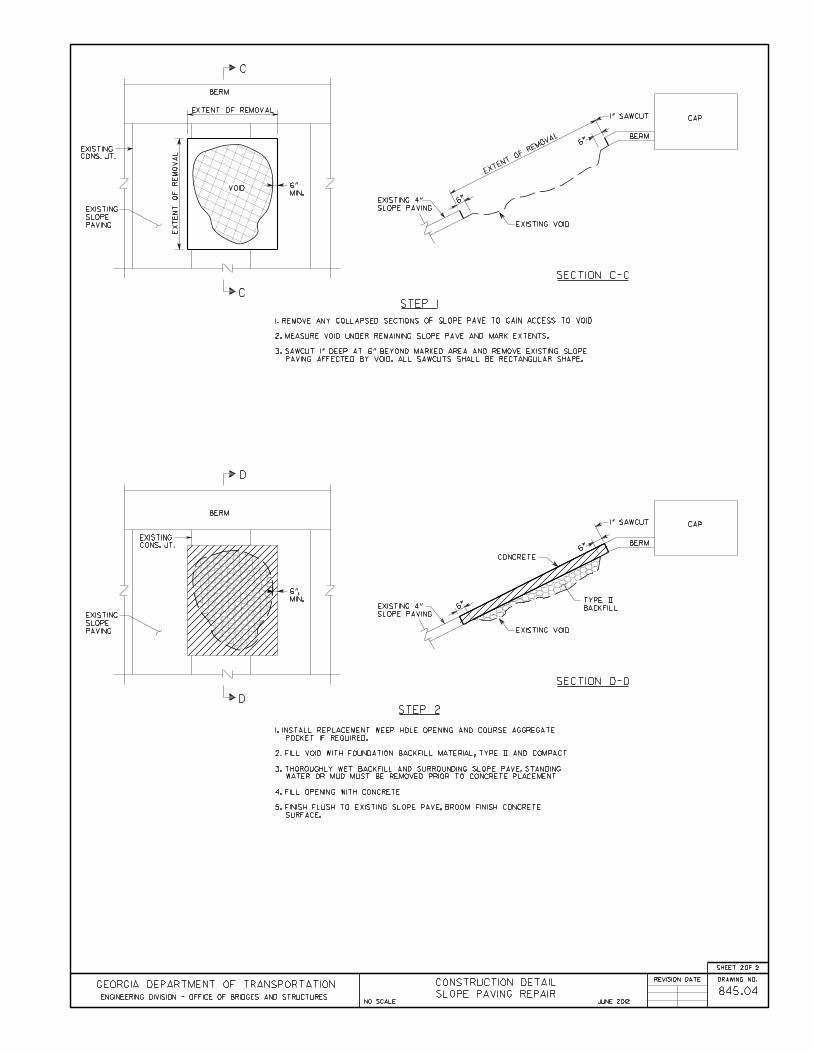

Chapter 2 Bridge Structure Maintenance Activities
Version 06.01.12 2-204
Activity 845.05 – Approach Slab Settling
General Notes:Verify all dimensions and elevations in the field prior to ordering materials or buildingforms. Light lines indicate the existing structure and heavy lines indicate the new structure.
This repair can only be used on bridges with integral backwalls.
Material Specifications: Concrete: Flowable Fill, ƒ′c = 125 psi
Safety Traffic Control
o GDOT Operations Work Zone Traffic Control, oro GDOT Standard Drawings 9100 thru 9107 and MUTCD Part 6 – Temporary
Traffic Control
Georgia Standard Specifications Section 600 – Controlled Low Strength Flowable Fill
Georgia Special Provisions & Supplemental Specifications: None
Qualified Products List: None
Before Repair After Repairs

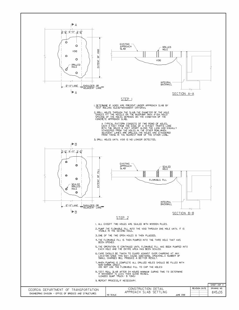

Version 06.01.12 3-207
3 Preventive Maintenance
A rigorous and constant program of preventative maintenance can extend the service life of abridge ensure that the maximum value is realized from the initial capital investment.Additionally regular maintenance proves more cost effective that occasional major repair.
Preventive maintenance is defined as activities that will maintain components of the bridge andforestall development of a structural deficiency. Preventive maintenance activities can beclassified into two groups: scheduled and response.
o Scheduled - Typical activities that are conducted on a scheduled interval basisinclude: cleaning decks, seats, caps, and salt splash zones; cleaning bridge drainage systems; cleaning joints; sealing concrete decks or substructure elements.
o Response – Activities identified through the inspection process. Typically theseactivities are performed on an as-needed basis and include: painting structural steel members removing debris from waterway channels; removing brush; maintain spillways in approach slab adjacent to the bridge. replacing joints
A program of preventive maintenance is most effective when applied to bridge elements onstructures with significant remaining service life. The concept of preventive bridge maintenanceis built on the understanding that a program of multiple relatively small repairs and activities willkeep the bridge in good condition and thereby avoid the large expense of major rehabilitation orreplacement.
Activity Schedule
Task FrequencyDeckClean Deck and Gutters 2 YearsClean Deck Drains/Scuppers 2 YearsClean Joints YearlySeal Deck 6 Years
SuperstructureSpot Paint Steel Members As Needed
SubstructureClean Abutments/Caps As NeededRedress Rip Rap As Needed
SiteRemove Brush YearlyRemove Debris from Channel As NeededMaintain Spillway As Needed
Figure 3.1 - Activity Schedule for Preventive Maintenance

Chapter 3 Preventive Maintenance
Version 06.01.12 3-208
Clean Deck and Gutters
Procedure:
Coordinate work with District Environmentalist for required permits for washing.
Collect and remove trash, dirt, and other debris from deck and gutters by sweeping, shoveling,vacuuming, or other suitable methods. Loosen dirt and debris with scrapers and stiff brushes, asnecessary.
Pressure or Flood wash the structure, generally beginning at the highest point and workingdownward, using clean, fresh water. If bridge is located in a sag vertical curve, verify properdrainage before commencing work. Avoid direct discharge of water into streams or waterways.
Safety: Traffic Control
o GDOT Operations Work Zone Traffic Control, oro GDOT Standard Drawings 9100 thru 9107 and MUTCD Part 6 – Temporary
Traffic Control
Equipment:
Traffic Control, as needed. High-pressure water pump w/ hoses. Personal safety equipment. Brooms/Shovels. Water trailer. Wheel Barrow
Materials: Non-Potable Water

Chapter 3 Preventive Maintenance
Version 06.01.12 3-209
Clean Deck Drains and Scuppers
Procedure:
Coordinate work with District Environmentalist for required permits for washing.
Flush scuppers and drainage system, but prevent sediment and debris from discharging intostreams or waterways.
Remove scupper gratings and downspout clean-out plugs to flush and snake trapped debris, asnecessary.
Use caution to control water pressure used in flushing drainage systems.
Safety: Traffic Control
o GDOT Operations Work Zone Traffic Control, oro GDOT Standard Drawings 9100 thru 9107 and MUTCD Part 6 – Temporary
Traffic Control
Equipment:
Traffic Control, as needed. High-pressure water pump w/ hoses. Personal safety equipment. Sewer snake. Water trailer. Wheel Barrow
Brooms/Shovels.
Materials: Non-Potable Water

Chapter 3 Preventive Maintenance
Version 06.01.12 3-210
Clean Expansion Joints
Procedure:
Use brooms and shovels to remove excess debris near the joint. Remove debris build up in theexpansion joint, exercising care as not to damage the expansion joint material.
Safety: Traffic Control
o GDOT Operations Work Zone Traffic Control, oro GDOT Standard Drawings 9100 thru 9107 and MUTCD Part 6 – Temporary
Traffic Control
Equipment:
Traffic Control, as needed. Brooms/Shovels. Personal safety equipment. Wheel Barrow
Materials: None

Chapter 3 Preventive Maintenance
Version 06.01.12 3-211
Sealing Deck
Procedure:
Prior to work, patch deck spalls in accordance with Activity 810.01 – Deck Spall Repair andGeorgia DOT Special Provision 521 – Patching Concrete Bridge Deck.
Work shall be performed in accordance with Special Provision 519 – Two-Part Polymer BridgeDeck Overlay.
Safety:
Traffic Controlo GDOT Operations Work Zone Traffic Control, oro GDOT Standard Drawings 9100 thru 9107 and MUTCD Part 6 – Temporary
Traffic ControlEquipment:
Traffic Control, as needed. Shot Blaster. Personal safety equipment. Sand Blaster/Air Gun. Bucket and rollers. Spreader for aggregate.
See Activity 810.01 for add. mat’l.
Materials: Deck overlay Material Aggregate

Chapter 3 Preventive Maintenance
Version 06.01.12 3-212
Clean Abutment/Caps
Procedure:
Coordinate work with District Environmentalist for required permits for washing.
Collect and remove trash, dirt, and other debris from deck and gutters by sweeping, shoveling,vacuuming, or other suitable methods. Loosen dirt and debris with scrapers and stiff brushes, asnecessary.
Pressure wash the structure using clean, fresh water. Avoid direct discharge of water intostreams or waterways.
Safety: Traffic Control
o GDOT Operations Work Zone Traffic Control, oro GDOT Standard Drawings 9100 thru 9107 and MUTCD Part 6 – Temporary
Traffic Control Verify presence of lead paint system.
Equipment:
Traffic Control, as needed. High-pressure water pump w/ hoses. Personal safety equipment. Brooms/Shovels. Water trailer.
Materials: Non-Potable Water

Chapter 3 Preventive Maintenance
Version 06.01.12 3-213
Redress Rip Rap
Procedure:
Clear the area of debris and vegetation. Layout filter fabric and overlay with a layer of rip rapfrom 18” to 24” thick.
Safety: Traffic Control
o GDOT Operations Work Zone Traffic Control, oro GDOT Standard Drawings 9100 thru 9107 and MUTCD Part 6 – Temporary
Traffic Control Use special care near streams and rivers.
Equipment:
Traffic Control, as needed. Personal safety equipment.
Materials: Rip Rap, Type I Filter Fabric

Chapter 3 Preventive Maintenance
Version 06.01.12 3-214
Brush/Tree Removal
Procedure:
Cut and remove vegetation from around substructures and approaches (5’ from outside edge ofbridge opening), minimizing removal to limit habitat loss, erosion, and sedimentation.
Cut and remove trees to the groundline. Apply approved herbicide to kill the trees root system.
Safety: Traffic Control
o GDOT Operations Work Zone Traffic Control, oro GDOT Standard Drawings 9100 thru 9107 and MUTCD Part 6 – Temporary
Traffic Control Use special care near streams and rivers.
Equipment:
Traffic Control, as needed. Personal safety equipment. Chainsaw
Materials: Herbicide

Chapter 3 Preventive Maintenance
Version 06.01.12 3-215
Debris Removal
Procedure:
Coordinate work with District Environmentalist for required permits.
Cut and remove debris from the river channel and overbank area.
Safety: Traffic Control
o GDOT Operations Work Zone Traffic Control, oro GDOT Standard Drawings 9100 thru 9107 and MUTCD Part 6 – Temporary
Traffic Control Use special care near streams and rivers.
Equipment:
Traffic Control, as needed. Chainsaw Personal safety equipment. Gradall/Boom Truck
Truck (Dump)
Materials: None

Chapter 3 Preventive Maintenance
Version 06.01.12 3-216
Maintain Spillways
Procedure:
Collect and remove trash, dirt, and other debris from spillways by sweeping, shoveling,vacuuming, or other suitable methods. Loosen dirt and debris with scrapers and stiff brushes, asnecessary.
Pressure or Flood wash spillways, but prevent sediment and debris from discharging into streamsor waterways.
Safety: Traffic Control
o GDOT Operations Work Zone Traffic Control, oro GDOT Standard Drawings 9100 thru 9107 and MUTCD Part 6 – Temporary
Traffic Control
Equipment:
Traffic Control, as needed. High-pressure water pump w/ hoses. Personal safety equipment. Sewer snake. Water trailer.
Materials: Non-Potable Water

Appendix
Version 06.01.12 A-217
APPENDIX A – GENERAL REFERENCED DOCUMENTS
AASHTO Standard Specifications for Highway Bridges, 17th Edition
AASHTO Manual for Bridge Evaluation, 2nd Edition, with 2011 Interim Revisions
AASHTO/AWS D1.5M/D1.5:2010 Bridge Welding Code, 6th Edition, with 2011 AASHTOInterim Revisions
HEC-23 Bridge Scour and Stream Instability Countermeasures Experience, Selection, andDesign Guidance
Manual on Uniform Traffic Control Devices, 2009 Edition

Appendix
Version 06.01.12 A-218
APPENDIX B – SPECIAL PROVISIONS
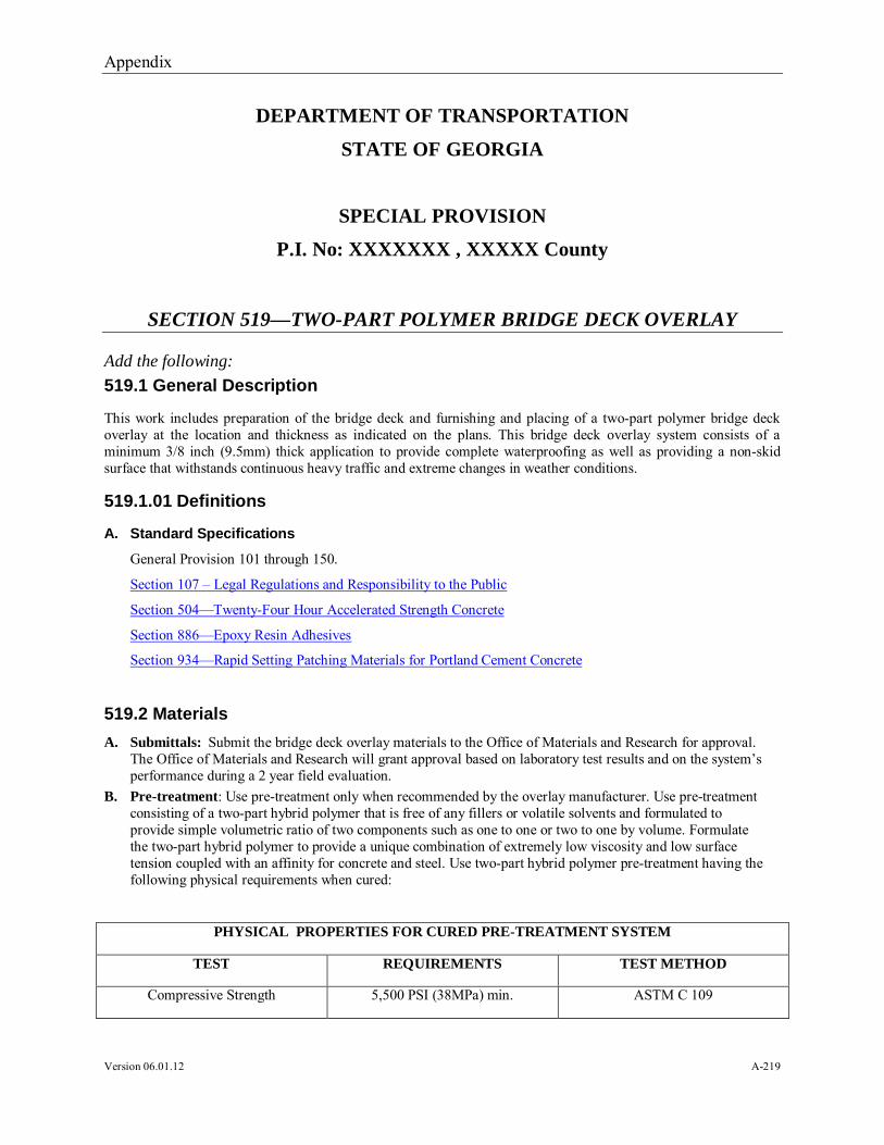
Appendix
Version 06.01.12 A-219
DEPARTMENT OF TRANSPORTATION
STATE OF GEORGIA
SPECIAL PROVISION
P.I. No: XXXXXXX , XXXXX County
SECTION 519—TWO-PART POLYMER BRIDGE DECK OVERLAY
Add the following:
519.1 General Description
This work includes preparation of the bridge deck and furnishing and placing of a two-part polymer bridge deckoverlay at the location and thickness as indicated on the plans. This bridge deck overlay system consists of aminimum 3/8 inch (9.5mm) thick application to provide complete waterproofing as well as providing a non-skidsurface that withstands continuous heavy traffic and extreme changes in weather conditions.
519.1.01 Definitions
A. Standard Specifications
General Provision 101 through 150.
Section 107 – Legal Regulations and Responsibility to the Public
Section 504—Twenty-Four Hour Accelerated Strength Concrete
Section 886—Epoxy Resin Adhesives
Section 934—Rapid Setting Patching Materials for Portland Cement Concrete
519.2 Materials
A. Submittals: Submit the bridge deck overlay materials to the Office of Materials and Research for approval.The Office of Materials and Research will grant approval based on laboratory test results and on the system’sperformance during a 2 year field evaluation.
B. Pre-treatment: Use pre-treatment only when recommended by the overlay manufacturer. Use pre-treatmentconsisting of a two-part hybrid polymer that is free of any fillers or volatile solvents and formulated toprovide simple volumetric ratio of two components such as one to one or two to one by volume. Formulatethe two-part hybrid polymer to provide a unique combination of extremely low viscosity and low surfacetension coupled with an affinity for concrete and steel. Use two-part hybrid polymer pre-treatment having thefollowing physical requirements when cured:
PHYSICAL PROPERTIES FOR CURED PRE-TREATMENT SYSTEM
TEST REQUIREMENTS TEST METHOD
Compressive Strength 5,500 PSI (38MPa) min. ASTM C 109

Appendix
Version 06.01.12 A-220
Tensile Strength 3,100 PSI (21MPa) min. ASTM D 638
Tensile Elongation 30% min. ASTM D 638
Water Adsorption 0.10% max. ASTM D 570
Shore “D” Hardness 65 min. ASTM D 2240
Pot Life 40-70 minutes GDT-58
Adhesion to Concrete 100% failure in concrete ACI-503-R (Pull Out Test)
C. Bridge Deck Overlay: Use a bridge deck overlay consisting of a two-part polymer that is free of any fillersor volatile solvents and formulated to provide simple volumetric mixing ratio of two components such as oneto one or two to one by volume. Use a two-part polymer system formulated to provide flexibility in thesystem without any sacrifice of the hardness, chemical resistance or strength of the system. Do not useexternal or conventional plasticizers. Introduce flexibility by interaction of elastomers to chemically link inthe process of curing so that the flexibility of the molecule is minimally affected during the low temperatureconditions that are confronted in actual use. Use a two-part polymer overlay system having the followingphysical properties when cured:
PHYSICAL PROPERTIES FOR CURED TWO PART POLYMER OVERLAY SYSTEM
TEST REQUIREMENTS TEST METHOD
Compressive Strength 7,000 PSI (48MPa) min. ASTM C 109
Tensile Strength 2,500 PSI (17MPa) min. ASTM D 638
Tensile Elongation 30% min. ASTM D 638
Water Adsorption 0.20% max. ASTM D 570
Shore “D” Hardness 60 min. ASTM D 2240
Pot Life 15-40 minutes GDT-58
Flexural Creep 0.0065” (0.17mm) in 7 days California Method 419
Adhesion to Concrete 100% failure in concrete ACI-503-R (Pull Out Test)
D. Aggregate: Use bauxite, crushed porphyry, aluminum oxide or other similarly hard durable aggregates asrecommended by the manufacturer and approved by the Engineer. Use embedded exposed aggregateconforming to the following gradation.
FINE AGGREGATE GRADATION
SIEVE SIZE % PASSING BY WEIGHT
No. 4 100
No. 20 0 – 5

Appendix
Version 06.01.12 A-221
No. 200 0 –1.0
Broadcast coarse aggregate conforming to the following gradation over the first layer of polymer, immediatelyprior to broadcasting fine aggregate.
COARSE AGGREGATE GRADATION
SIZE % PASSING BY WEIGHT
5/8” 98 - 100
½” 55 – 60
3/8” 12 – 14
¼” 0 - 1
519.2.01 Delivery, Storage and Handling
Deliver all materials in their original containers, bearing the manufacturer’s label, specifying date of manufacture,batch number, trade name brand, quantity and mixing ratio.
Store all materials to prevent damage from the elements and to insure the preservation of its quality and fitness forthe work. Avoid contact with flame.
Inspect all stored materials, although accepted before storage, prior to their use in the work. Ensure that all storedmaterials meet the requirements of the Contract at the time of use.
Remove from the site of the work immediately, any material rejected because of failure to meet the required testsor rejected because of damage. Replace all removed material at no additional cost to the Department.
519.3 Construction Requirements
519.3.01 Preparation
A. Removal and Preparation of Repair Area
Sound all visual bridge deck defects of greater than 1” X 6” (25mm X 150mm) to determine the limits of thedamaged areas. Strike the deck surface around the defect with a hammer, chain drag, or other similar tool todetect unsound concrete having a “flat” or “hollow” sound. Mark the limits of the defective areas on the deckby making a rectangular area 2 inches (50mm) beyond the outer limits of the unsound concrete area to serve asa guide for sawing. Mark spalled areas within less than 6 inches (150mm) of each other as one spall area.
Saw the rectangular marked areas with near vertical faces not less than one inch (25mm) in depth. Exerciseextreme care not to saw or damage the reinforcing steel. Remove all unsound material within the sawed areas.Remove concrete to a minimum depth of 1/2 inch (13mm) below the top mat of reinforcing steel by powerchipping or hand tools. Do not use pneumatic hammers heavier than a 15 lb. class (nominal). Do not operatepneumatic hammers and chipping tools at an angle exceeding 60 degrees relative to the surface of the deckslab. Such tools may be started in the vertical position but must be immediately tilted to a 60 degree operationangle. Clean all exposed reinforcing steel of all rust, corrosion products, oil, dirt, concrete fragments, loosescale and any other coating of any character that would destroy or inhibit the bond with the patching material.Exercise utmost care not to damage or fracture the sound concrete substrate left on the bottom of the spallrepair area. Do not use sharp pointed bits.
Appendix
Version 06.01.12 A-222
Hold “over-cutting” of the bridge deck beyond marked areas to the minimum amount possible. Thoroughlyclean all “over-cutting” of “saw slurry” and other contaminants. Then repair by filling full-depth with anapproved Type II epoxy adhesive as specified in Section 886. Make such repairs as soon as possible.
Just prior to placing the patching material, thoroughly clean the surfaces within the repair areas by abrasiveblasting and air blasting to remove any oil, dust, dirt, slurry from saw operation, and other contaminants.Remove abrasives from the blasting operation from the bridge deck. During blasting, protect traffic in adjacentlanes.
B. Placement of Patching Material
The Contractor shall use Repair Method No. 1 or Method No. 2 as described below. For both repair methods,ensure the surface within the repair areas is dry and thoroughly cleaned of all contaminants immediately beforeplacement. Use air compressors equipped with suitable traps capable of removing all surplus water and oil inthe compressed air for cleaning repair areas. Do not use contaminated air. Use air compressors capable ofdelivering compressed air at a continuous pressure of 90 psi (620kPa).
Ensure the finished surface meets a surface tolerance of 1/16 inch (1.6mm). Utilize such approved measures asnecessary to keep the deck surface adjacent to the patching operation reasonably clean of excess grout andother materials at all times. Unless otherwise specified, complete all patching operations and open all lanes totraffic before sunset each day.
1. Repair Method No. 1 (24 Hour Accelerated Strength Concrete)
After the repair area preparation is complete, completely coat all concrete surfaces within the repair area witha film of Type II epoxy at a thickness of 10 to 20 mils (0.25 to 0.50mm).
Use concrete meeting the requirements of Section 504. Mix the concrete on site. Use a mix design andmixing method approved by the Laboratory. Deposit concrete in the repair area while the epoxy is stilltacky and vibrate sufficiently to form a dense, homogeneous mass of concrete, completely filling the areaof the patch. Screed the concrete to the proper grade and allow to remain undisturbed until the water sheendisappears from the surface. Then cover the concrete with wet burlap or membrane curing compound.Continue curing for a minimum of 3 hours. The Engineer may require a longer curing time to ensuresufficient strength development of the concrete prior to opening to traffic.
2. Repair Method No. 2 (Rapid Setting Patching Material)
Follow the above requirements for Repair Method No. 1. Additionally, prepare the surfaces in the repairareas in accordance with the manufacturer’s written recommendations. Handle, mix, place, consolidate,screed, and cure the patching material in accordance with the manufacturer’s written instructions asapproved by the Laboratory. Continue curing for at least one hour and until the section is opened to traffic.
519.3.02 Construction
A. Surface Preparation: Clean the bridge deck by shotblasting to remove any oil, dirt, rubber or any otherpotentially detrimental material such as curing compound and laitance which may prevent proper bonding andcuring of the material.
The Contractor is directed to Section 107 of the Standard Specifications giving the Contractor responsibilityfor the work site, and requiring conformance to all federal, state, and local laws relating to pollution controland worker protection. In particular, ensure that the Contractor is familiar with and in full compliance withthe provisions of the laws concerning the management of waste and worker protection.
Do not allow construction traffic on any portion of the deck that has been shotblasted or on the overlaywithout specific approval of the Engineer. Overlay the deck surface within 24 hours of the surface preparationoperation.
Ensure all surfaces to be overlaid are dry at the time of application. Immediately before applying the overlaysystem, clean all prepared surfaces with compressed air (or vacuum) to remove dust and debris. Use aircompressors equipped with a filter to prevent oil in the air supply. Do not apply the overlay system when rain
Appendix
Version 06.01.12 A-223
is forecast to occur within 24 hours of application. Do not apply the overlay system unless the minimumambient temperature is 50o and rising.
If, in the opinion of the Engineer, the surface has become soiled or contaminated prior to the application ofthe overlay, re-clean the surface to the satisfaction of the Engineer at no additional cost to the Department.
B. Field Test: Prior to commencing the overlay operation, place a test area of overlay on the bridge deck.Prepare the area for the test overlay as described above. Ensure the test is large enough so the cleaningequipment and methods to be employed in the full-scale operation can be used for the field test. Ensure thedegree of cleaning used on the test area is the minimum used on the remainder of the structure. Use theapplication of the overlay system to the test area to establish proper procedures and techniques for applyingthe overlay to the full structure.
After the test area has cured for 72 hours, check adhesion in accordance with ACI 503R-1980. Test aminimum of three sample areas. Ensure no adhesion test has an adhesive strength less than 250 psi (1725kPa)and the minimum average value for the 3 tests is greater than 300 psi (2070kPa).
If the test of a sample area fails to meet the above requirements due to a cohesive failure of the concretesubstrate, the adhesive strength of the sample area will be considered acceptable. Successful completion ofthe adhesive strength tests will be required before the full-scale overlay operation is to begin.
C. Application: Provide suitable coverings, such as heavy duty drop cloths, to protect all exposed areas not tobe overlaid, such as curbs, railings, parapets, deck drains, locations of expansion joints that are to receiveexpansion joint membranes, etc. Clean or repair any damage or defacement resulting from the application, atthe Contractor’s expense, to the satisfaction of the Engineer.
Ensure the application of the overlay system is done by the supplier, or by a factory trained or licensedapplicator, with written approval from the manufacturer of the overlay system.
Ensure each component of the two-part polymer is metered, mixed together, and distributed onto the deck bymachine. Use a dispensing machine capable of ratio check verification at the pump outlets as well as cyclecounting to monitor output. Ensure the in line mixing is motionless so as not to overly shear the material.Ensure the machine makes maximum use of the working time of the polymer by mixing it immediately priorto dispensing onto the deck.
Provide the number of layers and the application rates of the materials in the various layers as recommendedby the manufacturer in order to achieve a minimum 3/8 inch (9.5mm) and maximum½ inch (13mm) overlaythickness when measured from the top of the concrete substrate to the top of the polymer (not the peaks of theaggregate). Ensure the application of the overlay system is as follows:
1. APPLICATION OF POLYMER: After mixing of the components, evenly distribute the polymer on theclean, dry deck surface at the rate recommended by the manufacturer.
2. APPLICATION OF AGGREGATE: After application of each layer of polymer, allow a minimum lapseperiod as required by the manufacturer’s instructions before broadcasting the aggregate. Ensure themethod and rate of aggregate application is in accordance with the manufacturer’s recommendations.
3. CONSOLIDATION: If required by the manufacturer, use a hand operated roller as approved by theEngineer and the manufacturer within 10 minutes of the aggregate application to evenly consolidate theaggregate into the polymer.
4. REMOVAL OF EXCESS AGGREGATE: After initial cure, remove excess aggregate by a powervacuum or other Engineer approved method prior to the application of subsequent layers of polymer.
5. APPLICATION OF ADDITIONAL LAYERS: Additional layers may be applied immediately after theinitial set of the preceding layer (as determined by the Manufacturer and Engineer) and removal of allexcess aggregate. The maximum time allowed between each layer shall be at the discretion of theEngineer and the Manufacturer and may vary depending on the temperature and circumstances of theproject. Ensure joints are staggered and overlapped between successive layers so that no ridges willappear.

Appendix
Version 06.01.12 A-224
6. TRAFFIC CONSIDERATIONS: Traffic may be allowed on the final layer after the polymer hasreached its final cure (as determined by the Manufacturer) and after removal of all excess, looseaggregate.
7. OVERLAY SURFACE: Ensure the finished surface consists of a uniform coat of imbedded exposedaggregate.
519.3.03 Quality Acceptance
A. Thickness Verification
Ensure the overlay is at least 3/8” (9.5mm) thick as measured from the concrete substrate to the top of thepolymer at three random locations for every 1000 yd2 (830 m2) of surface area. Recoat thin areas as describedabove and re-verify thickness at no additional cost to the Department. This verification may consist of cores,holes, etc., but in all cases repair any areas tested to destruction before final acceptance.
In thin areas that have been recoated to obtain the required minimum thickness, the Engineer may requireadditional adhesion strength tests in accordance with ACI 503R-29 to verify the Contractor’s procedure forrecoating existing overlay.
519.3.04 Contractor Warranty and Maintenance
The polymer manufacturer and the Contractor, by acceptance of the work described in this Specification, shalljointly agree to guarantee the wearing surface against all defects incurred during normal traffic use for a period often years. Submit this agreement in writing to the Engineer signed by both the polymer manufacturer and theContractor. Commence the ten year period on the date of acceptance of the work. The guarantee shall cover alllabor and materials required by the Department to satisfactorily repair and replace the wearing surface.
519.4 Measurement
519.4.01 Surface Preparation:
Measure the area of the deck acceptably repaired and blast cleaned prior to installation of the overlay in squareyards (meters) computed from surface measurements taken to the nearest 0.1 foot (30mm). Do not measure theblast cleaning of any longitudinal or transverse construction joints or vertical surfaces for payment.
519.4.02 Polymer Overlay:
Measure the area of the deck acceptably overlaid with polymer and broadcast spread crushed aggregate in squareyards (meters) computed from surface measurements taken to the nearest 0.1 foot (30mm).
519.5 Payment
519.5.01 Surface Preparation:
Surface preparation is paid for by the square yard (meter) of the deck acceptably repaired and blast cleaned priorto installation of the overlay. Payment includes all expenses associated with removal of existing concrete, repairand blast cleaning operations.
519.5.02 Polymer Overlay:
Polymer overlay is paid for by the square yard (meter) of the deck overlaid, complete in place and accepted,provided, however, that the specified minimum overlay thickness requirement is met. The individual layersnecessary to attain the specified thickness will not be paid for individually. Payment includes all labor and materialcost, procurement, handling, hauling and processing, coring for thickness verification, guarantee, and includes allequipment, tools, labor, and incidentals necessary to complete the work.
Payment will be made under:Item No. 519 Surface Preparation Per square yard (meter)
Item No. 519 Polymer Overlay Per square yard (meter)

Appendix
Version 06.01.12 A-225
Item No. 519-0515 Surface Preparation per Square Yard (Meter)
Item No. 519-0530 Polymer Overlay per Square Yard (Meter)
Appendix
Version 06.01.12 A-226
DEPARTMENT OF TRANSPORTATION
STATE OF GEORGIA
SPECIAL PROVISION
P.I. No: XXXXXXX , XXXXX County
SECTION 521 – PATCHING CONCRETE BRIDGE DECK
521.1 General Description
This work includes partial depth patching of spalls in a concrete bridge deck by removing the broken, damaged, ordisintegrated concrete. This work also includes removing any patches from spalled or damaged areas of the bridgedeck surface and patching them with approved patching materials according to this Specification.
521.1.01 Definitions
General Provisions 101 through 150.
521.1.02 Related References
A. Standard Specifications
Section 504—Twenty-Four Hour Accelerated Strength Concrete
Section 886—Epoxy Resin Adhesives
Section 934—Rapid Setting Patching Materials for Portland Cement Concrete
B. Referenced Documents
QPL 27
521.1.03 Submittals
General Provisions 101 through 150.
521.2 MaterialsEnsure that the materials used to repair and patch concrete bridge deck conform to the rapid setting patchingmaterial requirements.
521.2.01 Delivery, Storage, and Handling
General Provisions 101 through 150.
521.3 Construction Requirements
521.3.01 Personnel
General Provisions 101 through 150.
521.3.02 Equipment
To clean the repair areas, use air compressors equipped with traps that can remove surplus water and oil in thecompressed air. Ensure that the compressor can deliver compressed air at a continuous pressure of at least 90 psi(620 kPa).
The Engineer will check the compressed air daily for contamination. Do not use contaminated air.

Appendix
Version 06.01.12 A-227
521.3.03 Preparation
A. Removing and Preparing the Repair Area
Prepare to perform partial patching of spalled areas as follows:
a. “Sound” bridge deck with visual defects to determine the limits of the damaged areas. Strike the decksurface with a hammer, chain drag, or similar tool to detect unsound concrete that sounds flat or hollow.
Omit any defect for repair that is less than 1 in. by 6 in. by 0.5 in. (25 by 150 by 12 mm) deep.
b. Mark the limits of the defective areas on the deck by making a rectangle 6 in. (150 mm) beyond the outerlimits of the unsound concrete area as a guide for sawing.
c. Mark spalled areas less than 6 in. (150 mm) from each other as one spall area.
d. Saw the rectangular marked areas with near vertical faces at least 1 in. (25 mm) deep. Exercise extremecare not to saw or damage the reinforcing steel.
e. Remove unsound material within the sawed area to a minimum depth of 1 in (25 mm) below the top mat ofreinforcing steel with power chipping or hand tools. Pneumatic hammers heavier than 15 lb. class nominal(30 lb. maximum) are not permitted.
f. Operate pneumatic hammers and chipping tools at an angle not to exceed 60 degrees relative to the surfaceof the deck. After starting tool in the vertical position, immediately tilt the tool to a 60 degree operatingangle.
g. Do not damage or fracture the sound concrete substrate to be left on the bottom of the spall area. Do not usesharp pointed bits.
h. Clean all exposed reinforcing steel of all rust and corrosive products including oil, dirt, concrete fragments,loose scale and any other coating of any character that would destroy or inhibit the bond with the patchingmaterial.
i. Immediately before placing the patching material, thoroughly clean the surfaces within the repair areas bysandblasting and air blasting to remove oil, dust, dirt, slurry from saw operation, and other contaminants.
521.3.04 Fabrication
General Provisions 101 through 150.
521.3.05 Construction
A. Concrete Patching
Patch concrete safely and rapidly to minimize inconvenience to the traveling public.
1. Accomplish this work with other operations in progress within an area if possible.2. Remove and replace completed patches that contain cracks, shrinkage, compression failures, or are
damaged by construction or traffic before Final Acceptance at no cost to the Department.
B. Placing Patching Material
Use Repair Method 1 unless the Engineer gives written approval to use Repair Method 2. Use Repair Method 1when the average daily temperature is 50 °F (10 °C) or above. Use of Repair Method 2, if approved, is limitedto the manufacturer’s written recommendations.
For the following repair methods, begin the placement when the surface within the repair area is dry andthoroughly free of contaminants.
Ensure that the finished surface meets a surface tolerance of 1/16 in. (1.5 mm).
Use approved measures as necessary to keep the deck surface adjacent to this operation free of excess grout andother materials. Unless otherwise specified, complete the patching operations and open to traffic before sunseteach day.

Appendix
Version 06.01.12 A-228
1. Repair Method 1: Twenty-four Hour Accelerated Strength Concrete
Use this method as follows:
a. Completely coat the concrete surface areas within the repair area with a film of Type II epoxyapproximately 10 to 20 mils (0.25 to 0.50 mm) thick.
b. Mix the concrete on site in a portable mixer. Obtain approval for the mix design and mixing methodfrom the laboratory. The material must meet a slump range of 1.0 in. (25 mm) to 3.0 in. (75 mm).
c. Deposit the concrete in the repair area while the epoxy is still tacky. Vibrate it to form a dense,homogeneous mass of concrete that completely fills the patch area.
d. Screed the concrete to the proper grade and do not disturb it until the water sheen disappears from thesurface.
e. Cover the concrete with wet burlap or membrane curing compound. Allow the curing to continue for atleast three hours. The Engineer may require longer curing to ensure sufficient concrete strengthdevelopment before opening to traffic.
2. Repair Method 2: Rapid Setting Patching Material
a. In addition to the requirements outlined in Subsection 451.3.03.A, “Removing and Preparing theRepair Area,” prepare the surfaces in the repair areas according to the manufacturer’s writtenrecommendations.
b. Perform the patching material handling, mixing, placing, consolidating, screeding, and curingaccording to the manufacturer’s written recommendations as approved by the laboratory.
c. Continue curing for at least one hour and until opening the section to traffic.
C. Special Requirements
The following special requirements apply to this work:
1. During sandblasting, protect traffic in the adjacent lanes.
2. After the sandblasting operations:
a. Thoroughly clean the area to be repaired with compressed air.
b. Remove sand from the sandblasting operation from the bridge deck.
3. Do not “over-cut” the bridge deck beyond marked areas whenever possible.
4. Remove saw slurry and other contaminates from the over-cutting.
5. Repair the over-cuts by filling full-depth with an approved low-viscosity epoxy compound using a Type IIepoxy adhesive specified in Section 886. Make these repairs as soon as possible.
521.3.06 Quality Acceptance
General Provisions 101 through 150.
521.3.07 Contractor Warranty and Maintenance
General Provisions 101 through 150.
521.4 MeasurementThe area measured for payment is the number of square feet (meters) of patching complete in place and accepted.
521.4.01 Limits
General Provisions 101 through 150.
Appendix
Version 06.01.12 A-229
521.5 Payment
The area measured as specified above will be paid for at the Contract Unit Price per square foot (meter). Payment isfull compensation for equipment, tools, labor, incidentals to complete the work, including but not limited to:
Removing existing patching material or the spalled, broken, or damaged concrete
Cleaning the open area by sandblasting
Furnishing, placing, finishing, and curing the patching material
Payment will be made under:
Item No. 521 Patching concrete bridge deck Per square foot (meter)
521.5.01 Adjustments
General Provisions 101 through 150.

Appendix
Version 06.01.12 A-230
DEPARTMENT OF TRANSPORTATION
STATE OF GEORGIA
SPECIAL PROVISION
P.I. No: XXXXXXX , XXXXX County
SECTION 521 – PATCHING CONCRETE BRIDGE
Add the following:
521.1 General Description
This work includes patching of substructure or superstructure concrete bridge components by removing the concrete,cleaning existing reinforcement, adding supplemental reinforcement when required, and patching with approvedconventional or accelerated Portland cement concrete or rapid setting patching materials according to thisSpecification and as shown on the Plans.
521.1.01 Definitions
General Provisions 101 through 150.
“Sound” – the act of striking a concrete surface with a chipping hammer or similar tools to detect unsound concrete.
521.1.02 Related References
A. Standard Specifications
Section 500—Concrete Structures
Section 504—Twenty-Four Hour Accelerated Strength Concrete
Section 511—Reinforcement Steel
Section 853—Reinforcement and Tensioning Steel
Section 886—Epoxy Resin Adhesives
Section 934—Rapid Setting Patching Materials for Portland Cement Concrete
B. Referenced Documents
QPL 10
QPL 27
521.1.03 Submittals
General Provisions 101 through 150.
521.2 Materials
Ensure that the materials used to repair and patch bridge components meet the following requirements:
A. Portland Cement Concrete Patching Materials
1. Conventional Portland Cement Concrete (Repair Method 1)
a. Use Class “A” or Class “AA” concrete or as indicated on the Plans.

Appendix
Version 06.01.12 A-231
b. Meets the requirements of Section 500 of the Specifications.
c. Use concrete manufactured at plants that qualify as approved sources according to the StandardOperating Procedure for Ready Mix Concrete. See QPL 10 for a list of approved plants.
2. Twenty-Four Hour Accelerated Strength Concrete (Repair Method 2)
a. Meets the requirements of Section 504 of the Specifications, except that the use of a portable concretemixer is required.
B. Rapid Setting Patching Materials (Repair Method 3)
1. Use rapid setting patching materials meeting the requirements of Section 934. See QPL 27 for a list ofapproved patching materials. Patching materials not listed on QPL 27 will require testing and approval bythe Office of Materials and Research before use.
2. When shown on the Plans, use Type III rapid setting patching material to patch vertical and overhead repairareas.
521.2.01 Delivery, Storage, and Handling
General Provisions 101 through 150.
521.3 Construction Requirements
521.3.01 Personnel
General Provisions 101 through 150.
521.3.02 Equipment
To clean the repair areas, use air compressors equipped with traps that can remove surplus water and oil in thecompressed air. Ensure that the compressor can deliver compressed air at a continuous pressure of at least 90 psi(620 kPa).
The Engineer will check the compressed air daily for contamination. Do not use contaminated air.
521.3.03 Preparation
A. Limits of Repair
Repair all patches as shown on the Plans and as directed by the Engineer.
B. Concrete Removal
1. Remove concrete to a minimum depth of 3¾” inches or as shown on the Plans with power chipping or handtools. Pneumatic hammers heavier than 15 lb. class nominal (30 lb. maximum) are not permitted. Exerciseextreme care not to saw or damage the reinforcing steel.
2. Operate pneumatic hammers and chipping tools at an angle not to exceed 60 degrees relative to the surfaceof the concrete. After starting the tool in the vertical position, immediately tilt the tool to a 60 degreeoperating angle.
3. Do not damage or fracture the sound concrete substrate to be left on the bottom of the patch area. Do notuse sharp pointed bits.
C. Surface Preparation
1. Clean all exposed reinforcing steel of all rust and corrosive products including oil, dirt, concrete fragments,loose scale and any other coating of any character that would destroy or inhibit the bond with the patchingmaterial.
2. Immediately before placing the patching material, thoroughly clean the surfaces within the repair areas bysandblasting and air blasting to remove oil, dust, dirt, slurry from saw operation, and other contaminants.

Appendix
Version 06.01.12 A-232
3. Place formwork as required to complete patch repair. Provide access in formwork for placement of patchmaterial.
4. Ensure that the finished surface meets a surface tolerance of 1/16 in. (1.5 mm).
5. Use approved measures as necessary to keep the adjacent concrete surfaces free of excess grout and othermaterials.
521.3.04 Fabrication
General Provisions 101 through 150.
521.3.05 Construction
A. Concrete Patching
Patch concrete safely and rapidly to minimize inconvenience to the traveling public.
1. Accomplish this work with other operations in progress within an area if possible.
2. Remove and replace completed patches that contain cracks, shrinkage, compression failures, or aredamaged by construction or traffic before Final Acceptance at no cost to the Department.
B. Placing Patching Material
Only use Repair Method 1 with the class of concrete on bridge components designated on the Plans.
Use Repair Method 2 unless the Engineer gives written approval to use Repair Method 3. Use Repair Method 1 and2 when the average daily temperature is 50 °F (10 °C) or above. Use of Repair Method 3, if approved, is limited tothe manufacturer’s written recommendations.
For the following repair methods, begin the placement when the surface within the repair area is dry and thoroughlyfree of contaminants.
1. Repair Method 1: Conventional Portland Cement Concrete
a. Completely coat the concrete surface areas within the repair area with a film of Type II epoxy adhesiveas specified in Section 886 approximately 10 to 20 mils (0.25 to 0.50 mm) thick or according to themanufacturer’s written recommendations.
b. Deposit the concrete in the repair area while the epoxy is still tacky. Vibrate it to form a dense,homogeneous mass of concrete that completely fills the patch area.
c. Screed the concrete to the proper grade and do not disturb it until the water sheen disappears from thesurface.
d. Cover the concrete with wet burlap or membrane curing compound. Allow the curing to continue untilthe required minimum design compressive strength is achieved as designated by the class of concreteused or as shown on the Plans. Complete curing prior to transferring load to the repaired section.
2. Repair Method 2: Twenty-Four Hour Accelerated Strength Concrete
a. Prepare, remove and place as outlined in Subsections 521.3.03 and 521.3.05.B and 521.3.05.B.1.
b. Mix the concrete on site in a portable mixer of adequate capacity. Obtain approval for the mix designand mixing method from the Office of Materials and Research.
c. The material must meet a slump range of 1.0 to 3.0 in. (25 to 75 mm).
3. Repair Method 3: Rapid-Setting Patching Material
a. In addition to the requirements outlined in Subsection 521.3.03, prepare the surfaces in the repair areasaccording to the manufacturer’s written recommendations.
b. Perform the patching material handling, mixing, placing, consolidating, finishing, and curing accordingto the manufacturer’s written recommendations as approved by the Office of Materials and Research.
Appendix
Version 06.01.12 A-233
c. Continue curing until a minimum design compressive strength of 3,500 psi (20 MPa) or as shown onthe Plans is achieved. Complete curing prior to transferring load to the repaired section.
C. Special Requirements
The following special requirements apply to this work:
1. During sandblasting, protect traffic in adjacent travel lanes.
2. After the sandblasting operations:
a. Thoroughly clean the area to be repaired with compressed air.
b. Remove sand from the sandblasting operation from adjacent concrete surfaces.
3. Do not “over-cut” concrete surfaces beyond marked areas whenever possible.
4. Remove saw slurry and other contaminates from the over-cutting.
5. Repair the over-cuts by filling full-depth with an approved low-viscosity epoxy compound using a Type IIepoxy adhesive specified in Section 886. Make these repairs as soon as possible.
521.3.06 Quality Acceptance
General Provisions 101 through 150.
521.3.07 Contractor Warranty and Maintenance
General Provisions 101 through 150.
521.4 Measurement
The area measured for payment is the number of square feet (meters) of patching complete in place and accepted.
521.4.01 Limits
General Provisions 101 through 150.
521.5 Payment
The area measured as specified above will be paid for at the Contract Unit Price per square foot (meter). Payment isfull compensation for equipment, tools, labor, incidentals to complete the work, including but not limited to:
• Removing existing patching material or the spalled, broken, or damaged concrete
• Cleaning the open area by sandblasting
• Furnishing, placing, finishing, and curing the patching material
• Supplemental reinforcement
Payment will be made under:
Item No. 521 Patching concrete bridge Per square foot (meter)
521.5.01 Adjustments
General Provisions 101 through 150.
Bridge Management Unit

Appendix
Version 06.01.12 A-234
DEPARTMENT OF TRANSPORTATION
STATE OF GEORGIA
SPECIAL PROVISION
P.I. No: XXXXXXX , XXXXX County
SECTION 527 – MISCELLANEOUS CONCRETE REPAIR
Add the following:
527.1 General Description
This work consists of repairing concrete by locating existing reinforcing steel and miscellaneous concreteembedments within the vicinity of the repair; saw cutting concrete; removing deteriorated concrete and/or existingpatch material and installing concrete patch material.
All work will be in accordance with this Specification, the Plans and as directed by the Engineer.
527.1.01 Definitions
General Provisions 101 through 150
“Sound” – the act of striking a concrete surface with a chipping hammer or similar tools to detect unsound concrete.
527.1.02 Related References
A. Standard Specifications
Section 500 – Concrete Structures
Section 511 – Reinforcement Steel
Section 853 – Reinforcement and Tensioning Steel
Section 886 – Epoxy Resin Adhesive
Section 934 – Rapid Setting Patching Materials for Portland Cement Concrete
B. Referenced Documents
QPL 15
QPL 27
527.1.03 Submittals
Submit Working Drawings and Material Specifications that describe the details and materials required to adequatelycomplete the repair work including concrete patch material. Include written procedures required to complete therepair work.
527.1.04 Repair of Damage Caused by Contractor’s Operations
Repair any damage caused by construction operations and procedures to any part of the existing structure to thesatisfaction of the Engineer, at the expense of the Contractor. If required, provide design computations and

Appendix
Version 06.01.12 A-235
drawings to repair the damage caused by construction operations and procedures. Computations will be made by aProfessional Engineer, registered in the State of Georgia, in the employ of the Contractor.
527.2 Materials
Ensure that the materials used to repair and patch bridge components meet the following requirements:
A. Rapid Setting Patching Materials
Use rapid setting patching materials meeting the requirements of Section 934. See QPL 27 for a list of approvedpatching materials. Patching materials not listed on QPL 27 will require testing and approval by the Office ofMaterials and Research before use.
Use Type I Class A rapid setting patching material to patch vertical and overhead repair areas.
527.2.01 Delivery, Storage, and Handling
General Provisions 101 through 150.
527.3 Construction Requirements
527.3.01 Personnel
General Provisions 101 through 150.
527.3.02 Equipment
To clean the repair areas, use air compressors equipped with traps that can remove surplus water and oil in thecompressed air. Ensure that the compressor can deliver compressed air at a continuous pressure of at least 90 psi(620 kPa).
The Engineer will check the compressed air daily for contamination. Do not use contaminated air.
527.3.03 Preparation
A. Limits of Repair
Repair all damaged concrete as shown on the Plans and as directed by the Engineer. Determine limits of repairs asfollows:
1. “Sound” concrete surface with visual defects to determine the limits of the damaged areas. Strike thesurface with a chipping hammer or similar tools to detect unsound concrete. Concrete that is loose orexhibits a flat or hollow sound is considered unsound.
2. Mark the limits of the defective areas on the concrete surface by making a rectangle 2 in. (50 mm) beyondthe outer limits of the unsound concrete area as a guide for saw cuts.
3. Obtain approval from the Engineer on the limits of each repair prior to saw cutting.
B. Concrete Removal
1. Prior to any concrete work, utilize a Profometer 3 Rebar Locator (by Proceq) or an approved equivalent tolocate existing reinforcing steel and prestressing strands in the concrete.
2. Saw the rectangular marked areas a minimum of 1/2 in. (12 mm) deep or as shown on the plans. Exerciseextreme care not to saw or damage the reinforcing steel or prestressing strands.
3. Remove unsound material within the sawed area to a minimum depth of 2 inches for unreinforced concreteor 0.5 in. (12 mm) below the reinforcing steel or prestressing stands, or as shown on the Plans with powerchipping or hand tools. Pneumatic hammers heavier than 13.5 lb. class nominal (30 lb. maximum) are notpermitted. Exercise extreme care not to saw or damage the reinforcing steel or prestressing strands.
4. Operate pneumatic hammers and chipping tools at an angle not to exceed 60 degrees relative to the surfaceof the concrete. After starting the tool in the vertical position, immediately tilt the tool to a 60 degreeoperating angle.

Appendix
Version 06.01.12 A-236
5. Do not damage or fracture the sound concrete substrate to be left on the bottom of repair area. Do not usesharp pointed bits.
C. Surface Preparation
1. Clean all exposed reinforcing steel of all rust and corrosive products including oil, dirt, concrete fragments,loose scale and any other coating of any character that would destroy or inhibit the bond with the patchingmaterial.
2. Immediately before placing the patching material, thoroughly clean the surfaces within the repair areas bysandblasting and air blasting to remove oil, dust, dirt, slurry from saw operation, and other contaminants.
3. Place formwork as required to complete patch repair. Provide access in formwork for placement of patchmaterial.
4. Ensure that the finished surface meets a surface tolerance of 1/16 in. (1.5 mm).
5. Use approved measures as necessary to keep the adjacent concrete surfaces free of excess grout and othermaterials.
527.3.04 Fabrication
General Provisions 101 through 150.
527.3.05 Construction
A. Concrete Patching
Patch concrete safely and rapidly to minimize inconvenience to the traveling public.
1. Accomplish this work with other operations in progress within an area if possible.
2. Remove and replace completed patches that contain cracks, shrinkage, compression failures, or aredamaged by construction or traffic before Final Acceptance at no cost to the Department.
B. Placing Patching Material
For the following repair method, begin the placement when the surface within the repair area is dry and thoroughlyfree of contaminants.
1. Rapid-Setting Patching Material
a. In addition to the requirements outlined in Subsection 521.3.03, prepare the surfaces in the repair areasaccording to the manufacturer’s written recommendations.
b. Perform the patching material handling, mixing, placing, consolidating, finishing, and curing accordingto the manufacturer’s written recommendations as approved by the Office of Materials and Research.
c. Continue curing until a minimum design compressive strength of 5,000 psi (34.5 MPa) or as shown onthe Plans is achieved. Complete curing prior to transferring load to the repaired section.
C. Special Requirements
The following special requirements apply to this work:
1. During sandblasting, protect traffic in adjacent travel lanes.
2. After the sandblasting operations:
a. Thoroughly clean the area to be repaired with compressed air.
b. Remove sand from the sandblasting operation from adjacent concrete surfaces.
3. Do not “over-cut” concrete surfaces beyond marked areas whenever possible.
4. Remove saw slurry and other contaminates from the over-cutting.

Appendix
Version 06.01.12 A-237
5. Repair the over-cuts by filling full-depth with an approved low-viscosity epoxy compound using a Type IIepoxy adhesive specified in Section 886. Make these repairs as soon as possible.
527.3.06 Quality Acceptance
General Provisions 101 through 150.
527.3.07 Contractor Warranty and Maintenance
General Provisions 101 through 150.
527.4 Measurement
The area measured for payment is the number of square feet (meters) of concrete repaired and accepted.
527.4.01 Limits
General Provisions 101 through 150.
527.5 Payment
The quantities as measured above will be paid for at the Contract Unit Price complete, in place, and accepted.Payment is full compensation for all equipment, tools, labor, supplies, testing, incidentals and direct and indirectcost to complete the work, including but not limited to:
• Removing spalled, broken, or damaged concrete
• Cleaning the open area by sandblasting
• Furnishing, placing, finishing, and curing the patching material
• Supplemental reinforcement
Payment will be made under:
Item No. 527 Miscellaneous Concrete Repair Per square foot (meter)
527.5.01 Adjustments
General Provisions 101 through 150.
Bridge Management Unit

Appendix
Version 06.01.12 A-238
DEPARTMENT OF TRANSPORTATION
STATE OF GEORGIA
SPECIAL PROVISION
P.I. No: XXXXXXX , XXXXX County
Section 528 – Epoxy Pressure Injection of Concrete Cracks
Add the following:
Epoxy Sealing of Concrete Cracks
528.1 General Description
This work consists of labor, material, equipment, and services necessary for repairing cracks greater than 0.02inches (0.25 mm) in the concrete deck overlay surface using gravity means. The Engineer will determine the extentof repair. The work shall comply with the Specifications including Special Provisions where applicable.
528.1.01 Definitions
General Provisions 101 through 150.
528.1.02 Related References
A. Standard Specifications
Section 886-Epoxy Resin Adhesives
B. Referenced Documents
General Provisions 101 through 150.
528.1.03 Submittals
General Provisions 101 through 150.
Submit product handling and use specifications from manufacturer of epoxy adhesive.
528.2 Materials
Ensure epoxy used for crack repair complies with the requirements of Section 886, Type V epoxy adhesive.
Ensure epoxy used for sealing cracks is a low viscosity, high modulus epoxy adhesive. Ensure the viscosity ofepoxy adhesive is no greater than 175 cps.
528.2.01 Delivery, Storage, and Handling
General Provisions 101 through 150.
Follow manufacturer’s recommendations for storage and handling of epoxy adhesive.
528.3 Construction Requirements

Appendix
Version 06.01.12 A-239
528.3.01 Personnel
General Provisions 101 through 150.
528.3.02 Equipment
For routing cracks, use hand held grinders with a masonry disc small enough to follow the line of the cracks.
528.3.03 Preparation
Perform grinding of the deck as required for riding quality requirements prior to repairing cracks.
Clean concrete surfaces using mechanical means to remove all dust, oil, grease, laitance, curing compounds, and anyother contaminants prior to placing epoxy adhesive.
528.3.04 Fabrication
General Provisions 101 through 150.
528.3.05 Construction
1. Seal concrete cracks as follows:a. Route a ¼ in (6 mm) deep vee-notch in the crack using a hand held grinder following closely the
line of the crack.b. Clean concrete surfaces using mechanical means.c. Prepare epoxy adhesive in accordance with the manufacturer’s specifications.d. Pour neat epoxy adhesive into vee-notched crack using gravity means. Continue placement until
the crack is completely filled.e. After crack filling is complete, clean the sealed cracks to the original concrete surface.
2. Perform grooving of deck after crack repair is complete and accepted by the Engineer.
528.3.06 Quality Acceptance
General Provisions 101 through 150.
528.3.07 Contractor Warranty and Maintenance
General Provisions 101 through 150.
528.4 Measurement
Repair of concrete cracks is measured for payment by linear foot (meter) of concrete crack repired, and includes allmaterials, equipment and labor necessary to complete the work.
528.4.01 Limits
General Provisions 101 through 150.
528.5 Payment
Payment for repair of concrete cracks as specified above is paid for at the Contract Unit price bid per linear foot.Such payment is full compensation for furnishing all equipment, labor and materials and performing the work inaccordance with the Plans and Specifications. Payment will be made under:
Item No. 528 Epoxy Sealing of Concrete Cracks Per linear foot (meter)

Appendix
Version 06.01.12 A-240
APPENDIX C – QUALITY PRODUCTS LIST
QPL Number Description
QPL-10 List of Approved Concrete Plants
QPL-12 Reinforcement Steel Fabricators
QPL-15 Epoxy Resin Adhesives
QPL-17 Special Surface Coating for Concrete
QPL-18 Special Protective Coating
QPL-19 Bar Supports
QPL-20 (A) Preformed Joint Filler and (B) Preformed Foam Joint Filler
QPL-27 Rapid Setting Patching Material
QPL-28 Filter Fabrics
QPL-38 Epoxy Powders for Coating Steel Reinforcing Bars & Coated Tie Wiresfor Epoxy Coated Reinforcing Bars
QPL-50 Wood Preserving Plants
QPL-53 Galvanizers
QPL-55 Steel Welded Wire for Concrete Reinforcement
QPL-56 Corrugated Metal Pipe
QPL-59 Miscellaneous Metal Fabricators
QPL-66 Silicone Joint Sealants
QPL-73 Bridge Paint Systems
Refer to the latest Qualified Products List from the Georgia Department of Transportation’swebsite (http://www.dot.ga.gov/doingbusiness/Materials/qpl/Pages/default.aspx) for qualifiedsources.
Related Documents