BRIDGE ASSESSMENT METHODS USING IMAGE PROCESSING AND INFRARED THERMOGRAPHY TECHNOLOGY Masato Matsumoto 1 Koji Mitani 2 F. Necati Catbas 3 Abstract Identifying appropriate applications for technology to assess the health and safety of bridges is an important issue for bridge owners around the world. Traditionally, highway bridge conditions have been monitored through visual inspection methods with structural deficiencies being manually identified and classified by qualified engineers and inspectors. More advanced and objective bridge inspections are required for monitoring long-term bridge performance. NEXCO-West has been working to develop non-destructive highway bridge inspection methods using high resolution digital image and infrared thermography technologies. This paper describes the results of a pilot project in Florida performed in conjunction with the University of Central Florida. Introduction Today, proper maintenance and management of deteriorating infrastructure under severe budget constraints have become serious issues for bridge owners. Traditionally, highway bridge conditions have been monitored through visual inspections with structural deficiencies being manually identified and classified by qualified engineers and inspectors. In Japan, NEXCO-West is performing periodic visual inspections for its expressway bridges at least every five years in order to monitor bridge conditions and expected future deterioration, as well as to prepare future plans for further detailed investigations and maintenance actions (NEXCO-West (2006) ). Similarly, in the United States, condition ratings of bridge components in the Federal Highway Administration (FHWA)’s Structure Inventory and Appraisal (SI&A) database are determined by bridge inspectors in the field for bridge elements. The information obtained from visual inspections has been used to assist bridge owners in making decisions regarding bridge maintenance, rehabilitation, and replacement. However, the quality of inspection results obtained through the traditional inspection approach depends on the individual inspector’s subjective judgment based on his/her knowledge and experience, as well as varying field conditions. In addition, these traditional inspection procedures require significant investments in both time and labor costs. These factors support the necessity for research and development for more reliable, objective and efficient bridge inspection methods. Under these circumstances, 1 Executive Vice President, NEXCO-West USA, Inc. 2 President & CEO, NEXCO-West USA, Inc. 3 Associate Professor and Associate Chair, Dept. of Civil, Environmental and Construction Engineering, University of Central Florida

Welcome message from author
This document is posted to help you gain knowledge. Please leave a comment to let me know what you think about it! Share it to your friends and learn new things together.
Transcript
BRIDGE ASSESSMENT METHODS USING IMAGE PROCESSING AND INFRARED THERMOGRAPHY TECHNOLOGY
Masato Matsumoto1 Koji Mitani2
F. Necati Catbas3 Abstract
Identifying appropriate applications for technology to assess the health and safety of bridges is an important issue for bridge owners around the world. Traditionally, highway bridge conditions have been monitored through visual inspection methods with structural deficiencies being manually identified and classified by qualified engineers and inspectors. More advanced and objective bridge inspections are required for monitoring long-term bridge performance. NEXCO-West has been working to develop non-destructive highway bridge inspection methods using high resolution digital image and infrared thermography technologies. This paper describes the results of a pilot project in Florida performed in conjunction with the University of Central Florida. Introduction
Today, proper maintenance and management of deteriorating infrastructure under severe budget constraints have become serious issues for bridge owners. Traditionally, highway bridge conditions have been monitored through visual inspections with structural deficiencies being manually identified and classified by qualified engineers and inspectors. In Japan, NEXCO-West is performing periodic visual inspections for its expressway bridges at least every five years in order to monitor bridge conditions and expected future deterioration, as well as to prepare future plans for further detailed investigations and maintenance actions (NEXCO-West (2006) ). Similarly, in the United States, condition ratings of bridge components in the Federal Highway Administration (FHWA)’s Structure Inventory and Appraisal (SI&A) database are determined by bridge inspectors in the field for bridge elements. The information obtained from visual inspections has been used to assist bridge owners in making decisions regarding bridge maintenance, rehabilitation, and replacement. However, the quality of inspection results obtained through the traditional inspection approach depends on the individual inspector’s subjective judgment based on his/her knowledge and experience, as well as varying field conditions. In addition, these traditional inspection procedures require significant investments in both time and labor costs. These factors support the necessity for research and development for more reliable, objective and efficient bridge inspection methods. Under these circumstances, 1 Executive Vice President, NEXCO-West USA, Inc. 2 President & CEO, NEXCO-West USA, Inc. 3 Associate Professor and Associate Chair, Dept. of Civil, Environmental and Construction Engineering, University of Central Florida
NEXCO-West has been applying innovative bridge condition assessment technology using infrared thermography and digital concrete surface imaging technology for its bridge structures. The infrared thermography technology is used before applying hammer sounding tests to detect possible subsurface deterioration including delamination or spall of concrete. This provides bridge inspection engineers with targeted objective information from pre-screened areas of the bridge that needs closer attention for sounding tests. In the traditional visual inspection approach, bridge inspectors prepare a summary of bridge condition factors and recommendations to bridge owners, submitted with the maps of crack existence and potential spall area. Traditionally, these maps are created manually, based on the sketch taken during the field data collection phase. In order to reduce the time required by inspectors in the field to make general structure condition assessments, NEXCO-West developed an innovative crack detection method using high quality digital image and image processing algorithms. The crack detection method, together with the infrared (IR) thermography technology, is currently contributing to efficient bridge inspection resources and budget allocations for expressways in Japan. This paper describes the mechanisms of these inspection technologies and presents results from an on-site pilot project performed to evaluate the feasibility of these technologies in Florida, USA.
Crack Detection using High Resolution Digital Imaging (HRDI)
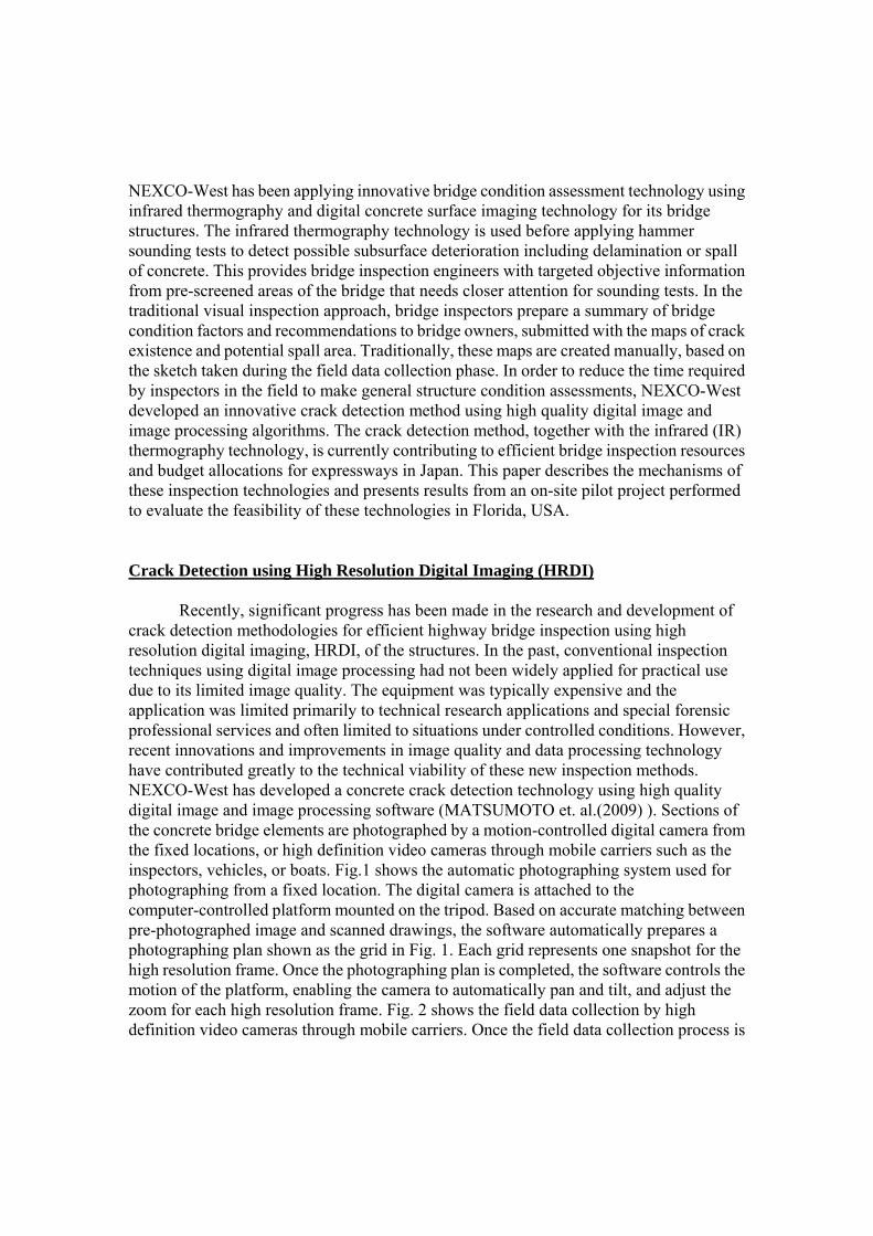
Recently, significant progress has been made in the research and development of crack detection methodologies for efficient highway bridge inspection using high resolution digital imaging, HRDI, of the structures. In the past, conventional inspection techniques using digital image processing had not been widely applied for practical use due to its limited image quality. The equipment was typically expensive and the application was limited primarily to technical research applications and special forensic professional services and often limited to situations under controlled conditions. However, recent innovations and improvements in image quality and data processing technology have contributed greatly to the technical viability of these new inspection methods. NEXCO-West has developed a concrete crack detection technology using high quality digital image and image processing software (MATSUMOTO et. al.(2009) ). Sections of the concrete bridge elements are photographed by a motion-controlled digital camera from the fixed locations, or high definition video cameras through mobile carriers such as the inspectors, vehicles, or boats. Fig.1 shows the automatic photographing system used for photographing from a fixed location. The digital camera is attached to the computer-controlled platform mounted on the tripod. Based on accurate matching between pre-photographed image and scanned drawings, the software automatically prepares a photographing plan shown as the grid in Fig. 1. Each grid represents one snapshot for the high resolution frame. Once the photographing plan is completed, the software controls the motion of the platform, enabling the camera to automatically pan and tilt, and adjust the zoom for each high resolution frame. Fig. 2 shows the field data collection by high definition video cameras through mobile carriers. Once the field data collection process is

completed, the software stitches the images collected from different angles at different distances and presents normal views of all structural surfaces, usually arranged as a single high-resolution composite image of the combined individual frames. The composite digital image is analyzed by image processing to determine the structure’s current condition as related to crack size, location and distribution. Innovative crack identification algorithms can identify and quantify concrete cracks as narrow as 0.008”, as illustrated in Fig. 3 which exceeds FHWA criteria (current FHWA inspection criteria requires crack detection by conventional means to 0.01 inch, or 0.25mm). Additionally, the crack size and length are determined by computer software and these quantitative characteristics are summarized in spread sheet format (Fig. 4). The obtained crack maps and supporting data are provided to engineers for their subsequent structural diagnosis and rehabilitation planning. A special advantage of this HRDI crack detection technology, with respect to crack identification and measurement, is the ease of maintaining a historical record of bridge cracks for use in monitoring crack propagation over time. The crack width, length and location data developed by using the system can provide powerful decision making support information for engineers with bridge maintenance planning responsibilities. It can also dramatically reduce data logging and long-term condition record-keeping and facilitates economic comparative evaluations on a recurring basis.
FIG.1: AUTOMATIC CAMERA SYSTEM (ACS)
FIG. 2: FIELD DATA COLLECTION BY HIGH DEFINITION VIDEO

Span 1Crack ID Location Width Length (m)
1-1 X=*, Y=* Hairline 1.41-2 X=*, Y=* Wide 1.71-3 X=*, Y=* Wide 1.31-4 X=*, Y=* Wide 1.01-5 X=*, Y=* Medium 3.41-6 X=*, Y=* Hairline 3.01-7 X=*, Y=* Hairline 3.71-8 X=*, Y=* Hairline 3.51-9 X=*, Y=* Hairline 3.01-10 X=*, Y=* … …
Span 2Crack ID Location Width Length (m)
2-1 X=*, Y=* … …2-2 X=*, Y=* … …2-3 X=*, Y=* … …2-4 X=*, Y=* … …2-5 X=*, Y=* … …2-6 X=*, Y=* … …2-7 X=*, Y=* … …2-8 X=*, Y=* … …2-9 X=*, Y=* … …2-10 X=*, Y=* … …
FIG. 3: ILLUSTRATIVE HDV RESULTS OF A PRESTRESSED CONCRETE BOX GIRDER
FIG. 4: ILLUSTRATIVE EXAMPLE FOR CRACK SUMMARY Infrared (IR) Thermography Technology
Infrared thermography technology is a non-destructive testing method to locate possible delamination and spalling of concrete through the monitoring of temperature variations on a concrete surface using a high-end infrared camera. IR technology offers inspectors the advantage of being able to identify likely delaminated, spalled and inner void areas from a distance of up to 60 meters with reasonable accuracy; thus avoiding the time and expense of gaining immediate access to the concrete surface to conduct traditional sounding tests. The results of IR images provide bridge owners a reliable screening of potential concrete defects on concrete structures that have been traditionally obtained by more time consuming (and possibly more expensive) sounding tests. By applying IR technology to the concrete inspection process, inspectors can focus their hands-on sounding test activities on those areas shown through IR imaging as likely to be defective. Fig.5 schematically illustrates the mechanism of the infrared thermography methodology. The red line depicts daily temperature variation for delaminated concrete,

while the blue line illustrates the daily temperature variation for concrete in good condition. The delaminated concrete surface shows different temperature variation (see Fig. 6). Infrared imagery technology is applicable during the periods when temperature differentials are detectable over time (IR imagery period A and B in Fig.5). It is not always possible to detect delamination of concrete only from the color variation of infrared imagery since the concrete structure itself tends to have a temperature gradient depending on location and orientation with respect to the sun. AKASHI et. al (2006) performed the statistical and analytical study on the relationship between characteristics of temperature variation and inherent damage of the concrete, and developed an automatic damage classification system that can classify the damage rate into three categories; the classification categories being “Critical” (crack exists on concrete surface and immediate attention is required), “Caution” (crack exists within 2cm from the concrete surface and close monitoring is recommended) and “Indication” (currently satisfactory) (see Fig. 7). An illustrative IR inspection result of a prestressed concrete box girder is shown in Fig. 8. Raw infrared (IR) image data is filtered and rated into three categories by the software to indicate and evaluate the severity of subsurface defects in concrete structures. The monitor shows the raw, filtered and rated IR images at an inspection site in real time (Fig. 9). Additionally, the potential spall area is summarized in spread sheet format (Fig. 10) to provide quantitative data for bridge inspectors to prioritize repair or rehabilitation work. Calculating the total spall area for each span or bridge provides engineers with a quantifiable basis for prioritizing alternatives in a bridge structure rehabilitation plan and for planning future inspection frequency. In Japan, spalling of concrete debris from expressway bridges has become a serious issue. In order to prevent hazards to third parties, comprehensive sounding tests have been performed on all potentially hazardous concrete surfaces exposed to motorist and pedestrian traffic from the 1990s. Using IR thermography technology, engineers can check the delamination and/or spalling of concrete about three times faster than they can by conducting conventional sounding tests because IR technology applications require significantly less staging to secure adequate site access and correspondingly less traffic control to collect the required field data. Concurrently IR versus traditional sounding tests offer a 40% savings in cost. These techniques can also be beneficial to bridge owners here in the US.
FIG.5: TEMPERATURE VARIATION OF THE DAY

FIG. 6: MECHANISM OF INFRARED IMAGERY TECHNOLOGY
FIG. 7: DAMAGE RATING BY INFRARED IMAGERY TECHNOLOGY
FIG. 8: ILLUSTRATIVE IR RESULTS OF A PRESTRESSED CONCRETE BOX GIRDER
N
Subsurface Crack
Heat Flow
IR Imagery Period A IR Imagery Period B
Concrete Surface
Heat Flow
Delaminated Concrete Sound Concrete Sound Concrete Delaminated Concrete
Heat Flow Heat Flow
Subsurface Crack

FIG. 9: IR ON-SITE INSPECTION (REAL-TIME MONITOR)
FIG. 10: ILLUSTRATIVE EXAMPLE FOR POTENTIAL SPALL AREA SUMMARY Combining the Digital Crack Detection and Infrared Thermography Technologies
Crack detection technology using high resolution digital images provides bridge
inspectors with visual digital information on concrete surface conditions that have traditionally been obtained from close-up visual inspections. Concurrently, the IR imagery technology corresponds to the sounding tests that traditionally have been used to detect voids, delamination, and/or areas of spalled concrete (see Table 1). Most of the information from the visual inspection and the sounding tests can be obtained through a combined inspection using both of these technologies. Effectively combining these technologies can contribute to reduced time for on-site inspections and inspection report preparation, allowing engineers to have more opportunities to devote themselves to the engineering issues, such as structural diagnosis and strategic rehabilitation planning. The advantages of applying new inspection technologies include;
- Overcome some shortcomings of human subjectivity - Providing objective digital records for historical inspection data comparisons - Improve efficiencies in bridge inspection resource application - Identifying areas of bridges to be targeted for closer inspection and/or future
monitoring.
Thermal Image Software Output

Pilot Applications in the State of Florida In order to validate effectiveness of the new inspection technologies, a pilot inspection project was conducted through a joint research effort with University of Central Florida (UCF). The objective of the research project was to investigate the technologies on the selected bridges to objectively characterize these deteriorated bridges with a university-government-industry collaboration, by exploring the use of novel image based technologies in a way that the information generated through these technologies will provide useful data for the inspection and evaluation of civil infrastructure systems (Fig. 11). The Florida Department of Transportation (FDOT) District 5 provided expertise regarding operations, maintenance practices, real needs for improvement in the processes, and provided access to deteriorated bridges and inspection data, while UCF conducted research utilizing its knowledge in non-destructive evaluation and structural health monitoring. The efforts of this research project are to be designed to demonstrate the technologies, not only to validate the capability, but also to illustrate that they can be integrated into bridge owners’ asset management systems with some minor adjustments. A sample bridge shown in Fig. 12 was selected for the pilot application. Currently, the condition of the bridge is regularly monitored through established visual inspection procedures performed by FDOT certified bridge inspectors.
The underside of a concrete bridge deck was photographed by the Automatic Camera System. By magnifying the digital image on the computer, existing cracks were visually detected by an experienced engineer trained to interpret high resolution digital images (Fig. 13). The detected cracks were categorized into three ranks depending on their widths (Rank 1: ≤0.010” (0.25mm), Rank 2: 0.010” (0.25mm) to 0.030” (0.76mm), Rank 3: 0.030” (0.76mm) or greater). After obtaining the digital crack map, the FDOT certified bridge inspector provided the hands-on inspection using a traditional crack width ruler in order to evaluate the accuracy of the new bridge assessment method. Table 2 summarizes the results of comparison in crack widths detected by the new technology and traditional methods. The widths of the cracks detected through the high resolution digital image matched with the actual hands-on measurements by crack width ruler for all the evaluated cracks. The infrared images of the bridge deck underside were also photographed. Since the accuracy of damage identification using infrared imagery is greatly affected by daily temperature variation, accurate monitoring of the infrared (IR) photographing environment is essential. Fig. 14(a) shows the equipment that was used to monitor the temperature
TABLE 1: PURPOSE OF THE NEW INSPECTION TECHNOLOGIES
Purpose of Inspection Traditional Approach
Digital Crack Detection Surface Condition (ex. Crack map)
Visual inspection
Infrared Thermography Inner Void Delamination and
Spalling Hammer Sounding

condition on the concrete surface. Three concrete test pieces were attached to the deck surface to simulate the subsurface cracks or delamination at different depth from the surface. Taking infrared images of the concrete ‘set-up’ test pieces enables the field infrared imaging team to see if there is sufficient temperature difference between damaged and non-damaged areas at any given time, permitting further diagnostic IR imaging of the test area (Fig. 14(b)). During the photographing process, the infrared images of set-up test pieces were periodically checked in order to make sure that the field infrared imaging team is always in a proper IR imaging environment. Based on the temperature record, the best time for IR photographing for the deck underside was from 2pm to 6pm, during the time the temperature of the concrete deck stays higher than the ambient temperature. Fig. 15 depicts a sample IR inspection result for a deck underside. The infrared thermography image (Fig. 15(b)) shows a blue spot at the edge of the deck, and the software interpreted this thermal difference as a ‘Critical’ area shown in red spots (Fig. 15 (c)). The result of the infrared inspection was evaluated by the FDOT certified bridge inspector by applying a hammer sounding method for the areas detected as potentially delaminated by the software (Fig. 16). Fig. 17 illustrates an example of the hammer sounding result, where a hidden plastic sheet appeared from beneath the mortar after tapping by the hammer. The result indicates that the infrared thermography could successfully detect the subsurface defects which could not be seen from the concrete surface through regular visual inspection methods.
FIG. 11 UNIVERSITY-GOVERNMENT-INDUSTRY COLLABORATION
FIG. 12 SAMPLE BRIDGE IN MELBOURNE, FL
Current bridge maintenance practice Access to deteriorated bridges and inspection data
Apply non-destructive bridge assessment technologies
Research with knowledge of non-destructive evaluation and structural health monitoring

FIG. 13 HIGH RESOLUTION DIGITAL IMAGE AND CRACK MAPPING RESULT (DECK UNDERSIDE) TABLE 2: COMPASIRON OF CRACK WIDTHS
Crack # ACS Crack Detection
(High Resolution Image) FDOT Inspector
(Crack Width Ruler) Match
Crack #1 < 0.010″ (0.25mm)
(Narrow/Green) 0.006″ (0.15mm) (Narrow/Green)
OK
Crack # 2-1 < 0.010″(0.25mm)
(Narrow/Green)0.007″(0.18mm) (Narrow/Green)
OK
Crack # 2-2 0.010″ - 0.030″(0.76mm)
(Medium/Yellow) 0.025″(0.64mm)
(Medium/Yellow) OK
Crack # 3-1 0.010″- 0.030″(0.76mm)
(Medium/Yellow) 0.016″(0.41mm)
(Medium/Yellow) OK
Crack # 3-2 < 0.010″(0.25mm)
(Narrow/Green) 0.010″(0.25mm) (Narrow/Green)
OK
(a) CROSS SECTION (b) TEST PIECE UNDER THE DECK
FIG. 14: CONCRETE TEST PIECES FOR TEMPERATURE MONITORING
Crack#1
Crack#2-1
Crack#2-2 Crack#3-2
Crack#3-1

(a) DIGITAL IMAGE (b) THERMOGRAPHY (c) SOFTWARE OUTPUT
FIG. 15: SAMPLE IR INSPECTION RESULT FOR DECK UNDERSIDE FIG. 16: HAMMER SOUNDING BY FIG. 17: AFTER HAMMER SOUNDING FDOT CERTIFIED BRIDGE INSPECTOR
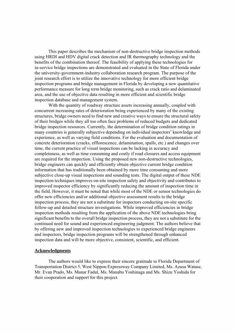
The High Definition Video (HDV) technology was applied to collect the deck top surface image. In order to record the deck surface cracks using HDV cameras, proper height (approximately 3 meters) and recording angle (no greater than 45° from vertical) are required. The HDV camera was attached to a custom-made camera mount and video data was gathered facing in the backward direction (Fig. 18). HDV recordings of the concrete deck surface were conducted at a speed of about 50km/h. Fig.19 shows an example of a high resolution image for a concrete deck surface. Cracks of 0.8mm or greater were visually detected by an experienced engineer, followed by the software-supported automatic crack detection. According to the Bridge Inspectors Field Guide (Florida Department of Transportation (2008)), cracks should be classified into three categories as shown in Table 3, and the NBI (National Bridge Inventory) specified “Distressed Area” is calculated for the rectangular area including “Significant,” “Moderate,” or “Severe” cracks. Inspectors are responsible for proposing priorities on rehabilitation to the bridge owners by comparing the “Distressed Area” for each span or bridge. The results of the pilot bridge
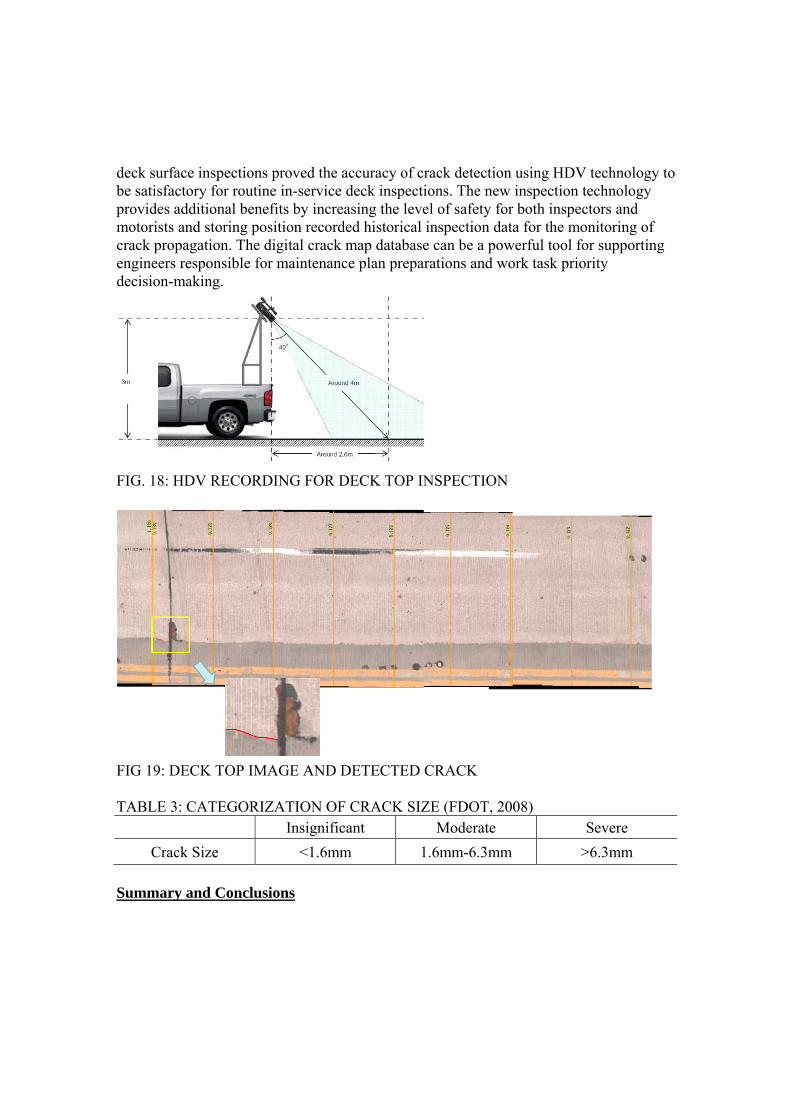
deck surface inspections proved the accuracy of crack detection using HDV technology to be satisfactory for routine in-service deck inspections. The new inspection technology provides additional benefits by increasing the level of safety for both inspectors and motorists and storing position recorded historical inspection data for the monitoring of crack propagation. The digital crack map database can be a powerful tool for supporting engineers responsible for maintenance plan preparations and work task priority decision-making.
FIG. 18: HDV RECORDING FOR DECK TOP INSPECTION
FIG 19: DECK TOP IMAGE AND DETECTED CRACK TABLE 3: CATEGORIZATION OF CRACK SIZE (FDOT, 2008)
Insignificant Moderate Severe
Crack Size <1.6mm 1.6mm-6.3mm >6.3mm
Summary and Conclusions
This paper describes the mechanism of non-destructive bridge inspection methods using HRDI and HDV digital crack detection and IR thermography technology and the benefits of the combination thereof. The feasibility of applying these technologies for in-service bridge inspections are demonstrated and evaluated in the State of Florida under the university-government-industry collaboration research program. The purpose of the joint research effort is to utilize the innovative technology for more efficient bridge inspection programs and bridge management in Florida by developing a new quantitative performance measure for long term bridge monitoring, such as crack ratio and delaminated area, and the use of objective data resulting in more efficient and scientific bridge inspection database and management system.
With the quantity of roadway structure assets increasing annually, coupled with concurrent increasing rates of deterioration being experienced by many of the existing structures, bridge owners need to find new and creative ways to ensure the structural safety of their bridges while they all too often face problems of reduced budgets and dedicated bridge inspection resources. Currently, the determination of bridge condition ratings in many countries is generally subjective depending on individual inspectors’ knowledge and experience, as well as varying field conditions. For the evaluation and documentation of concrete deterioration (cracks, efflorescence, delamination, spalls, etc.) and changes over time, the current practice of visual inspections can be lacking in accuracy and completeness, as well as time consuming and costly if road closures and access equipment are required for the inspection. Using the proposed new non-destructive technologies, bridge engineers can quickly and efficiently obtain objective current bridge condition information that has traditionally been obtained by more time consuming and more subjective close-up visual inspections and sounding tests. The digital output of these NDE inspection techniques improves on-site inspection safety and objectivity and contributes to improved inspector efficiency by significantly reducing the amount of inspection time in the field. However, it must be noted that while most of the NDE or sensor technologies do offer new efficiencies and/or additional objective assessment results to the bridge inspection process, they are not a substitute for inspectors conducting on-site specific follow-up and detailed structure investigations. While improved efficiencies in bridge inspection methods resulting from the application of the above NDE technologies bring significant benefits to the overall bridge inspection process, they are not a substitute for the continued need for sound and experienced engineering judgment. The authors believe that by offering new and improved inspection technologies to experienced bridge engineers and inspectors, bridge inspection programs will be strengthened through enhanced inspection data and will be more objective, consistent, scientific, and efficient.
Acknowledgments
The authors would like to express their sincere gratitude to Florida Department of Transportation District 5, West Nippon Expressway Company Limited, Ms. Azusa Watase, Mr. Evan Prado, Ms. Manar Fadul, Ms. Manabu Yoshinaga and Ms. Shizu Yoshida for their cooperation and support for this project.

References
AKASHI et. al (2006): Development of Inspection Method using Infrared Thermography Technology and its Technical Consideration, Proceeding of JSCE 61st Annual Meeting, 2006, PP 1113-1114 FLORIDA DEPARTMENT OF TRANSPORTATION (2008.2): Bridge Inspectors Field Guide Structural Elements MATSUMOTO et. al.(2009): Introduction of Non-Destructive Highway Inspection Methods using High Definition Video and Infrared Imaging Technology, The 34th IABSE Symposium, Venice, Italy
NEXCO-West (2006): ‘Inspection Standard - Bridges -‘
Related Documents