Breast lesion co-localisation between X-ray and MR images using finite element modelling Angela W.C. Lee a , Vijayaraghavan Rajagopal a , Thiranja P. Babarenda Gamage a , Anthony J. Doyle b,c , Poul M.F. Nielsen a,d , Martyn P. Nash a,d,⇑ a Auckland Bioengineering Institute, The University of Auckland, New Zealand b Auckland City Hospital, Auckland, New Zealand c Department of Anatomy with Radiology, The University of Auckland, New Zealand d Department of Engineering Science, The University of Auckland, New Zealand article info Article history: Available online 17 June 2013 Keywords: Breast biomechanical models Breast image registration Finite element modelling Multimodal breast image registration abstract This paper presents a novel X-ray and MR image registration technique based on individual-specific bio- mechanical finite element (FE) models of the breasts. Information from 3D magnetic resonance (MR) images was registered to X-ray mammographic images using non-linear FE models subject to contact mechanics constraints to simulate the large compressive deformations between the two imaging modal- ities. A physics-based perspective ray-casting algorithm was used to generate 2D pseudo-X-ray projec- tions of the FE-warped 3D MR images. Unknown input parameters to the FE models, such as the location and orientation of the compression plates, were optimised to provide the best match between the pseudo and clinical X-ray images. The methods were validated using images taken before and during compression of a breast-shaped phantom, for which 12 inclusions were tracked between imaging modal- ities. These methods were then applied to X-ray and MR images from six breast cancer patients. Error measures (such as centroid and surface distances) of segmented tumours in simulated and actual X- ray mammograms were used to assess the accuracy of the methods. Sensitivity analysis of the lesion co-localisation accuracy to rotation about the anterior–posterior axis was then performed. For 10 of the 12 X-ray mammograms, lesion localisation accuracies of 14 mm and less were achieved. This analysis on the rotation about the anterior–posterior axis indicated that, in cases where the lesion lies in the plane parallel to the mammographic compression plates, that cuts through the nipple, such rotations have rel- atively minor effects. This has important implications for clinical applicability of this multi-modality lesion registration technique, which will aid in the diagnosis and treatment of breast cancer. Ó 2013 Elsevier B.V. All rights reserved. 1. Introduction X-ray mammography is commonly used to image the breast to assist in the diagnosis and management of breast cancer. During X- ray mammography, the breasts are compressed to increase image contrast and minimise the radiation dose that is absorbed by the breast tissues. Mammograms are considered the gold-standard for breast screening and are useful for locating tumours and mi- cro-calcifications, which can often indicate the presence of cancer in the breasts (Ikeda, 2011). In order to diagnose and manage breast cancer, clinicians often compare mammograms to help interpret the images. This compar- ison may be performed between images of the same breast over time to observe the temporal changes in the breast tissues. Alter- natively, the asymmetry in the left and right breasts, or difference in the views of the same breast, taken at the same visit may be con- sidered. Mammograms are obtained with an individual in an up- right position and the breast is compressed between two plates. During X-ray mammographic screening for breast cancer, the breasts are usually compressed in the cranio-caudal (CC) and med- io-lateral oblique (MLO) directions, while during clinical diagnosis other views, such as lateral-medial (LM), medial–lateral (ML), and exaggerated cranio-caudal laterally (XCCL), may be acquired to provide better views of the region of interest. The different views of the internal structures of the breast tissues are acquired by alter- ing the position of the compression plates in relation to the breast tissues. Studies have shown that combining information from multiple modalities can aid in the diagnosis of breast cancer (Malur et al., 2001). MR images of the breast are typically acquired with the pa- tient in a prone position, with the breast hanging pendulously un- der the effect of gravity. The large deformations of the breast tissues between the two imaging modalities can make it difficult to co-localise information in the breast. Efforts to simulate mam- 1361-8415/$ - see front matter Ó 2013 Elsevier B.V. All rights reserved. http://dx.doi.org/10.1016/j.media.2013.05.011 ⇑ Corresponding author. E-mail addresses: [email protected], [email protected] (A.W.C. Lee), [email protected] (M.P. Nash). Medical Image Analysis 17 (2013) 1256–1264 Contents lists available at SciVerse ScienceDirect Medical Image Analysis journal homepage: www.elsevier.com/locate/media

Welcome message from author
This document is posted to help you gain knowledge. Please leave a comment to let me know what you think about it! Share it to your friends and learn new things together.
Transcript
Medical Image Analysis 17 (2013) 1256–1264
Contents lists available at SciVerse ScienceDirect
Medical Image Analysis
journal homepage: www.elsevier .com/locate /media
Breast lesion co-localisation between X-ray and MR images usingfinite element modelling
1361-8415/$ - see front matter � 2013 Elsevier B.V. All rights reserved.http://dx.doi.org/10.1016/j.media.2013.05.011
⇑ Corresponding author.E-mail addresses: [email protected], [email protected] (A.W.C. Lee),
[email protected] (M.P. Nash).
Angela W.C. Lee a, Vijayaraghavan Rajagopal a, Thiranja P. Babarenda Gamage a, Anthony J. Doyle b,c,Poul M.F. Nielsen a,d, Martyn P. Nash a,d,⇑a Auckland Bioengineering Institute, The University of Auckland, New Zealandb Auckland City Hospital, Auckland, New Zealandc Department of Anatomy with Radiology, The University of Auckland, New Zealandd Department of Engineering Science, The University of Auckland, New Zealand
a r t i c l e i n f o
Article history:Available online 17 June 2013
Keywords:Breast biomechanical modelsBreast image registrationFinite element modellingMultimodal breast image registration
a b s t r a c t
This paper presents a novel X-ray and MR image registration technique based on individual-specific bio-mechanical finite element (FE) models of the breasts. Information from 3D magnetic resonance (MR)images was registered to X-ray mammographic images using non-linear FE models subject to contactmechanics constraints to simulate the large compressive deformations between the two imaging modal-ities. A physics-based perspective ray-casting algorithm was used to generate 2D pseudo-X-ray projec-tions of the FE-warped 3D MR images. Unknown input parameters to the FE models, such as thelocation and orientation of the compression plates, were optimised to provide the best match betweenthe pseudo and clinical X-ray images. The methods were validated using images taken before and duringcompression of a breast-shaped phantom, for which 12 inclusions were tracked between imaging modal-ities. These methods were then applied to X-ray and MR images from six breast cancer patients. Errormeasures (such as centroid and surface distances) of segmented tumours in simulated and actual X-ray mammograms were used to assess the accuracy of the methods. Sensitivity analysis of the lesionco-localisation accuracy to rotation about the anterior–posterior axis was then performed. For 10 ofthe 12 X-ray mammograms, lesion localisation accuracies of 14 mm and less were achieved. This analysison the rotation about the anterior–posterior axis indicated that, in cases where the lesion lies in the planeparallel to the mammographic compression plates, that cuts through the nipple, such rotations have rel-atively minor effects. This has important implications for clinical applicability of this multi-modalitylesion registration technique, which will aid in the diagnosis and treatment of breast cancer.
� 2013 Elsevier B.V. All rights reserved.
1. Introduction in the views of the same breast, taken at the same visit may be con-
X-ray mammography is commonly used to image the breast toassist in the diagnosis and management of breast cancer. During X-ray mammography, the breasts are compressed to increase imagecontrast and minimise the radiation dose that is absorbed by thebreast tissues. Mammograms are considered the gold-standardfor breast screening and are useful for locating tumours and mi-cro-calcifications, which can often indicate the presence of cancerin the breasts (Ikeda, 2011).
In order to diagnose and manage breast cancer, clinicians oftencompare mammograms to help interpret the images. This compar-ison may be performed between images of the same breast overtime to observe the temporal changes in the breast tissues. Alter-natively, the asymmetry in the left and right breasts, or difference
sidered. Mammograms are obtained with an individual in an up-right position and the breast is compressed between two plates.During X-ray mammographic screening for breast cancer, thebreasts are usually compressed in the cranio-caudal (CC) and med-io-lateral oblique (MLO) directions, while during clinical diagnosisother views, such as lateral-medial (LM), medial–lateral (ML), andexaggerated cranio-caudal laterally (XCCL), may be acquired toprovide better views of the region of interest. The different viewsof the internal structures of the breast tissues are acquired by alter-ing the position of the compression plates in relation to the breasttissues.
Studies have shown that combining information from multiplemodalities can aid in the diagnosis of breast cancer (Malur et al.,2001). MR images of the breast are typically acquired with the pa-tient in a prone position, with the breast hanging pendulously un-der the effect of gravity. The large deformations of the breasttissues between the two imaging modalities can make it difficultto co-localise information in the breast. Efforts to simulate mam-

A.W.C. Lee et al. / Medical Image Analysis 17 (2013) 1256–1264 1257
mographic compression of the breast tissues from the prone grav-ity loaded shape of the breast include scaling, rotation, and trans-lation (Marti et al., 2004, 2006), geometric transforms (Kita et al.,2002; Behrenbruch et al., 2003, 2004) or volume-preserving affinetransformation of the three dimensional breast image (Mertzani-dou et al., 2012). Though these methods allow for fast calculations,they cannot reliably reconstruct the localised deformations of thebreast tissues from the prone to compressed states. For example,it has been shown that affine transformations were insufficientto recover the non-linear deformations of the breasts between dy-namic contrast enhanced MRI studies (Rueckert et al., 1999). Thus,for the much larger deformations of the breast tissues due to mam-mographic compressions, such simple transformations are mostlikely to be unsuitable.
Small-strain finite element (FE) models derived from prone MRIhave been proposed to simulate mammographic compressions(Hipwell et al., 2007). However, no validation of these linear FEmodels for mammographic breast compressions was performed,and since the small-strain theory is not valid for large deformations(>1%), the mechanics predictions are questionable. Finite strain for-mulations have thus been used to model compressive deforma-tions of the breasts (Tanner et al., 2010; Reynolds et al., 2011;Han et al., 2012).
The deformation of non-linear FE breast models due to com-pression has been modelled by either imposing displacementboundary conditions at the skin surface or by including contactmechanics in the FE simulations. Nodal displacements on the outersurfaces of the breast model have alternatively been fixed (Tanneret al., 2006), prescribed based on compression plate displacement(Azar et al., 2001; Hipwell et al., 2007; Ruiter et al., 2006; Tanneret al., 2008, 2010; Zhang et al., 2007), or explicitly prescribed usingthe deformation field from another non-rigid registration algo-rithm such as free form deformation based on B-splines or fluidregistration (Tanner et al., 2006, 2009, 2011). Methods which relyon image based non-rigid registration of the images require imag-ing data before and after the deformation of the breast tissues. Inprevious work (Tanner et al., 2006, 2009, 2011), 3D MR images ofthe breast before and after deformation of the breast tissues wereacquired. In contrast to these studies, during X-ray mammography,3D information of the breast deformations under compression istypically not acquired, as X-ray mammograms represent the 2Dprojections through compressed breast tissues. Thus these meth-ods are unlikely to be useful in simulating X-ray mammographiccompressions from the prone breast.
Ruiter et al. (2006) sought to overcome this limitation byenforcing nodal displacements on the skin surface of the FE modelbased on the two dimensional contours of the model compared tothe contour on the mammograms. Based on these methods, Hoppet al. (2011) visualised the dynamic contrast enhancement fromMR images overlaid onto mammograms. One problem with thisapproach is that explicitly defining the nodal displacements leadsto non-physical reaction forces at the skin surface of the FE model.This approach is the physical equivalent of having tethering pointsat the breast surface and pulling upon them. There are clearly nosuch boundary conditions on the breast tissues in the clinical situ-ation and the imposition of such unrealistic boundary constraintson the FE model may limit the ability of the FE models in predictingdeformations. In contrast to prescribing displacement boundaryconditions on the surface nodes of FE meshes (Ruiter et al., 2006;Tanner et al., 2008), a more physically realistic approach is to usecontact constraints to represent the effects of compression platesin the FE models (Reynolds et al., 2011; Chung et al., 2008a,b;Lee et al., 2011).
In order to simulate mammographic breast compressions fromprone MR data, boundary conditions reflecting the physical con-straints on the breasts during compression need to be defined.
Apart from the breast thickness after compression, other parame-ters describing the position of the compression plates such as pa-tient roll about the anterior–posterior (AP) axis, in-plane rotationand patient proximity are not recorded during X-ray mammogramexaminations. In prior work, simulating mammographic compres-sions from the prone breasts, these parameters were defined basedon subjective visual assessment (Tanner et al., 2008; Reynoldset al., 2011), explicitly prescribed based on randomly sampling dis-tributions (Tanner et al., 2008), or determined based on image sim-ilarity (Lee et al., 2011; Hopp et al., 2013).
In this paper, we describe a method for the non-rigid registra-tion of prone 3D MRI to 2D X-ray mammograms using non-linearFE models. This method was systematically validated using imagesfrom compression experiments on a breast phantom, and then ap-plied to clinical images from six breast cancer patients. An auto-mated iterative method for calculating the relative positioning ofthe compression plates with regards to the in-plane rotation andpatient proximity is presented and demonstrated using six patientcases. The sensitivity of the FE model to variations in the kinematicconstraints of mammographic compression simulations was inves-tigated for six patients using this framework. Identifying the rela-tive importance of parameters required for reliable compressionsimulations will be useful in developing physics-based FE modelsof the breasts. A biomechanical model that can accurately simulatethe deformations of the breast tissues from the prone to com-pressed states could also be used to predict the breast shape inthe supine orientation (the position required for ultrasound or sur-gery). A biophysical tool that can co-locate features across multiplemodalities will aid clinicians in the diagnosis and management ofbreast cancer.
2. Methods
In this paper, a novel breast mechanics modelling framework todetermine FE model parameters from MR and X-ray clinical imagesis presented. In order to predict breast deformations using FE mod-els, various assumptions need to be made regarding the tissueproperties and the boundary conditions. Studies have found thatthe errors associated with such assumptions of the FE models ofthe breasts remain unresolved (Tanner et al., 2006). Therefore, con-trolled experimental studies using a well-characterised breastshaped phantom were used to validate the modelling and imageanalysis framework. Then this validated FE modelling frameworkwas applied to register locations of breast lesions in six patients.
2.1. Multi-modality imaging
A breast shaped phantom (Triple Modality Biopsy TrainingPhantom, Model 051, Computerized Imaging Reference Systems,Virginia, USA) was imaged before and during 46% and 49% com-pressions in its AP and CC axes, respectively, using a 1.5 T SiemensMRI scanner and a GE Senographe DS X-ray mammography sys-tem. A custom built device was used to compress the breast phan-tom. This compression device allowed the breast phantom to becompressed prior to being placed in the X-ray mammography sys-tem. Due to the lack of constraints to restrict the breast phantomfrom rotating about its AP axis, stable deformation states couldonly be achieved with compressions in either the AP or CCdirections.
A T1 weighted FL3D pulse sequence was used for MR acquisitionand the imaging parameters were: dimensions 512 � 512 pixels;field of view 350 mm � 350 mm; 176 slices; slice thickness0.75 mm. The breast phantom contained 12 distinct inclusions, withdiameters ranging from 3 mm to 10 mm, which were visible underMR and X-ray imaging. This breast phantom was made with Zer-dine� and had a physical density similar to that of a 50% glandular
1258 A.W.C. Lee et al. / Medical Image Analysis 17 (2013) 1256–1264
breast (Bushberg et al., 2002). The phantom was 500 cc in volume,with a length of 120 mm, a height of 90 mm, and a width of 100 mm.
The clinical applicability of the proposed methods was demon-strated using MRI and X-ray mammography images acquired fromsix breast cancer patients with mean age of 49 years (range: 42–57 years). Dynamic contrast-enhanced MR images were acquiredwith the patients in a prone orientation using either a 1.5 T Sie-mens MRI scanner or 3 T Philips MRI scanner. Diagnostic X-raymammograms of the breast in CC, XCCL, MLO, ML or LM orienta-tions were acquired with a GE Senographe system.
2.2. Segmentation
The 12 inclusions in the breast phantom were segmented fromthe bulk of the breast phantom using a simple intensity threshold.Further details regarding the segmentation and modelling of theheterogeneities (inclusions) in the breast phantom are includedin the Supplementary document.
The breast images were automatically segmented using a multi-atlas method to identify boundaries between the fat, fibroglandularand muscle tissues (Aljabar et al., 2009; Rajagopal et al., 2011). Inthis method, an unseen image was compared to a database of breastimages that had associated segmentations of the fat, fibroglandularand muscle regions. A subset of these images was then selectedbased on their image similarity to the new image (as given by themutual information metric). The images were then automaticallyregistered with the new MR scan to find the optimal image align-ment. The warped segmentation images were combined usingshape space averaging to differentiate between the muscle andthe fat and fibroglandular regions (Rajagopal et al., 2011). Intensitythresholding was then used to differentiate between the fat andfibroglandular regions in the prone image (Otsu, 1979).
Tumours were identified by an expert radiologist on the X-raymammograms and in the prone MR images of the breasts for thesix patients. Based on this identification, the outlines of the tumoursas well as the locations of the nipples were manually segmented.
2.3. FEM compression and MR image warping
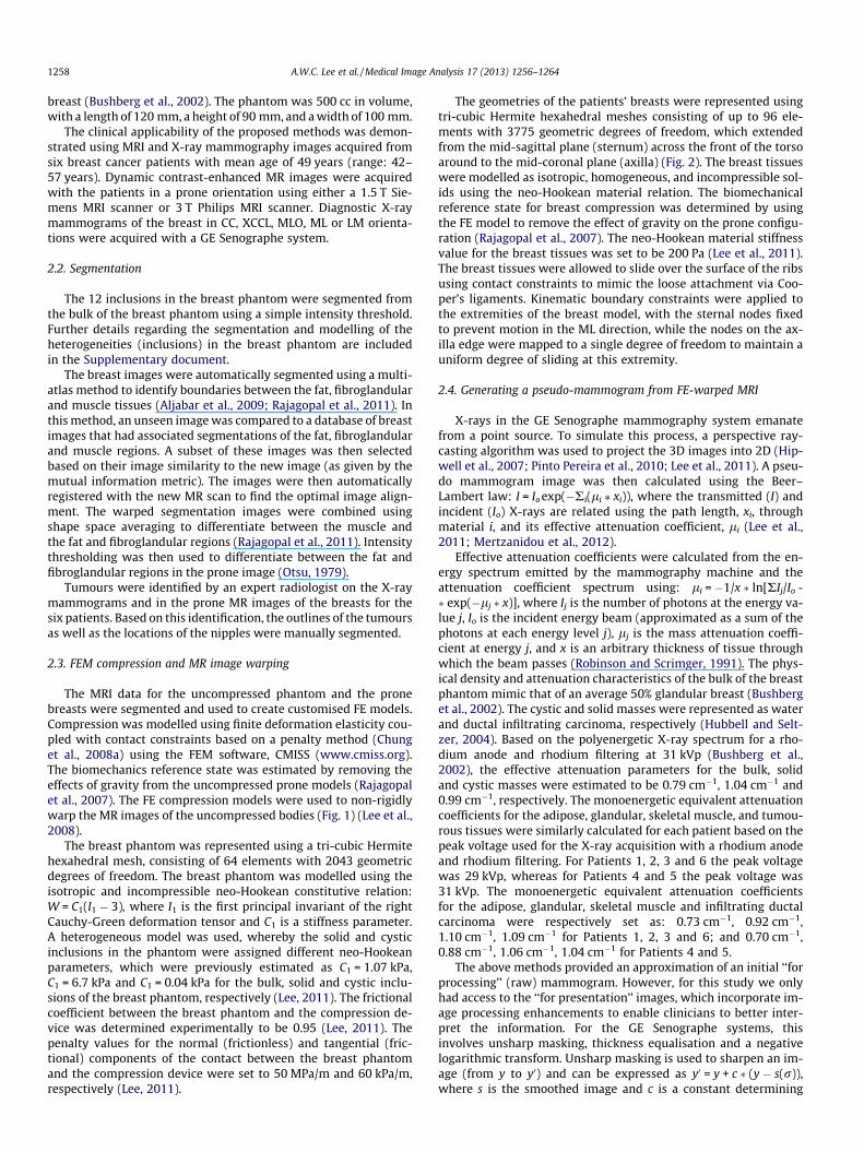
The MRI data for the uncompressed phantom and the pronebreasts were segmented and used to create customised FE models.Compression was modelled using finite deformation elasticity cou-pled with contact constraints based on a penalty method (Chunget al., 2008a) using the FEM software, CMISS (www.cmiss.org).The biomechanics reference state was estimated by removing theeffects of gravity from the uncompressed prone models (Rajagopalet al., 2007). The FE compression models were used to non-rigidlywarp the MR images of the uncompressed bodies (Fig. 1) (Lee et al.,2008).
The breast phantom was represented using a tri-cubic Hermitehexahedral mesh, consisting of 64 elements with 2043 geometricdegrees of freedom. The breast phantom was modelled using theisotropic and incompressible neo-Hookean constitutive relation:W = C1(I1 � 3), where I1 is the first principal invariant of the rightCauchy-Green deformation tensor and C1 is a stiffness parameter.A heterogeneous model was used, whereby the solid and cysticinclusions in the phantom were assigned different neo-Hookeanparameters, which were previously estimated as C1 = 1.07 kPa,C1 = 6.7 kPa and C1 = 0.04 kPa for the bulk, solid and cystic inclu-sions of the breast phantom, respectively (Lee, 2011). The frictionalcoefficient between the breast phantom and the compression de-vice was determined experimentally to be 0.95 (Lee, 2011). Thepenalty values for the normal (frictionless) and tangential (fric-tional) components of the contact between the breast phantomand the compression device were set to 50 MPa/m and 60 kPa/m,respectively (Lee, 2011).
The geometries of the patients’ breasts were represented usingtri-cubic Hermite hexahedral meshes consisting of up to 96 ele-ments with 3775 geometric degrees of freedom, which extendedfrom the mid-sagittal plane (sternum) across the front of the torsoaround to the mid-coronal plane (axilla) (Fig. 2). The breast tissueswere modelled as isotropic, homogeneous, and incompressible sol-ids using the neo-Hookean material relation. The biomechanicalreference state for breast compression was determined by usingthe FE model to remove the effect of gravity on the prone configu-ration (Rajagopal et al., 2007). The neo-Hookean material stiffnessvalue for the breast tissues was set to be 200 Pa (Lee et al., 2011).The breast tissues were allowed to slide over the surface of the ribsusing contact constraints to mimic the loose attachment via Coo-per’s ligaments. Kinematic boundary constraints were applied tothe extremities of the breast model, with the sternal nodes fixedto prevent motion in the ML direction, while the nodes on the ax-illa edge were mapped to a single degree of freedom to maintain auniform degree of sliding at this extremity.
2.4. Generating a pseudo-mammogram from FE-warped MRI
X-rays in the GE Senographe mammography system emanatefrom a point source. To simulate this process, a perspective ray-casting algorithm was used to project the 3D images into 2D (Hip-well et al., 2007; Pinto Pereira et al., 2010; Lee et al., 2011). A pseu-do mammogram image was then calculated using the Beer–Lambert law: I = Io exp(�Ri(li ⁄ xi)), where the transmitted (I) andincident (Io) X-rays are related using the path length, xi, throughmaterial i, and its effective attenuation coefficient, li (Lee et al.,2011; Mertzanidou et al., 2012).
Effective attenuation coefficients were calculated from the en-ergy spectrum emitted by the mammography machine and theattenuation coefficient spectrum using: li = �1/x � ln[RIj/Io -� exp(�lj � x)], where Ij is the number of photons at the energy va-lue j, Io is the incident energy beam (approximated as a sum of thephotons at each energy level j), lj is the mass attenuation coeffi-cient at energy j, and x is an arbitrary thickness of tissue throughwhich the beam passes (Robinson and Scrimger, 1991). The phys-ical density and attenuation characteristics of the bulk of the breastphantom mimic that of an average 50% glandular breast (Bushberget al., 2002). The cystic and solid masses were represented as waterand ductal infiltrating carcinoma, respectively (Hubbell and Selt-zer, 2004). Based on the polyenergetic X-ray spectrum for a rho-dium anode and rhodium filtering at 31 kVp (Bushberg et al.,2002), the effective attenuation parameters for the bulk, solidand cystic masses were estimated to be 0.79 cm�1, 1.04 cm�1 and0.99 cm�1, respectively. The monoenergetic equivalent attenuationcoefficients for the adipose, glandular, skeletal muscle, and tumou-rous tissues were similarly calculated for each patient based on thepeak voltage used for the X-ray acquisition with a rhodium anodeand rhodium filtering. For Patients 1, 2, 3 and 6 the peak voltagewas 29 kVp, whereas for Patients 4 and 5 the peak voltage was31 kVp. The monoenergetic equivalent attenuation coefficientsfor the adipose, glandular, skeletal muscle and infiltrating ductalcarcinoma were respectively set as: 0.73 cm�1, 0.92 cm�1,1.10 cm�1, 1.09 cm�1 for Patients 1, 2, 3 and 6; and 0.70 cm�1,0.88 cm�1, 1.06 cm�1, 1.04 cm�1 for Patients 4 and 5.
The above methods provided an approximation of an initial ‘‘forprocessing’’ (raw) mammogram. However, for this study we onlyhad access to the ‘‘for presentation’’ images, which incorporate im-age processing enhancements to enable clinicians to better inter-pret the information. For the GE Senographe systems, thisinvolves unsharp masking, thickness equalisation and a negativelogarithmic transform. Unsharp masking is used to sharpen an im-age (from y to y0) and can be expressed as y0 = y + c � (y � s(r)),where s is the smoothed image and c is a constant determining

Fig. 1. MR images of the uncompressed breast phantom were segmented to create FE models for simulating compression along the AP (a) and CC (b) axes of the phantom.
Fig. 2. FE model for simulating breast compression for Patient 1. The anterior (A),posterior (P), medial (M), lateral (L), cranial (Cr) and caudal (Ca) directions areshown.
A.W.C. Lee et al. / Medical Image Analysis 17 (2013) 1256–1264 1259
the level of enhancement (Bick and Diekmann, 2010). Blurring wasperformed using Gaussian smoothing.
Thickness equalisation compensates for the lower image inten-sities at the edge of the compressed breast by the addition of animage representing the tissue thickness (Bick and Diekmann,2010). A 2D image was generated by projecting through a 3D maskof the FE warped image. This projection image was then norma-lised, inverted, and multiplied with a correction factor to achievethe same intensity values of the bulk material (breast phantom)or adipose tissue (patients) in the generated pseudo X-rays asthe clinical X-ray images.
2.5. 2D rigid registration
A 2D rigid registration algorithm (ITK: ImageRegistration5) wasused to align the pseudo X-ray images with the experimental(breast phantom) and clinical (patients) X-ray images. Normalisedcross correlation was used as the image similarity measure, and agradient descent optimiser and a linear interpolation functionwere used in the registration process.
2.6. Validation using a breast-shaped phantom
The breast phantom was used to validate the process of predict-ing the compressed shape using the FE simulation to warp the MRimage, and then generating a pseudo X-ray image by projectingthrough the warped MR image.
The FE model of the breast phantom was compressed (subject tothe known boundary constraints imposed using the compressiondevice), and this deformation model was used to warp the seg-
mented images of the phantom. A 2D projection image was thengenerated from the 3D FE-warped image via the Beer–Lambert lawand compared with the experimental X-ray image (Fig. 3). Sincethe X-ray beams were not parallel, the relative location of the com-pressed phantom with respect to the compression plates needed tobe specified. 2D rigid registration (ITK: ImageRegistration5) was usedto define the in-plane rotation and translation of the compressedbreast phantom with respect to the compression plates. Based onthis rigid registration result, the location of the warped MR imagewas then updated and the pseudo X-ray image was regeneratedusing the projection algorithm until the in-plane transformationrepresented a shift of less than 1 pixel.
Landmark based measures such as the centroid location, thesurface distance (symmetric mean absolute surface distance,SMAD) of the outlines of the lesions, and the area overlap (Dicecoefficient) were evaluated for each of the inclusions (Babalolaet al., 2009).
Dice ¼ 2jAj \ BjjjAjj þ jBjj
� 100; j ¼ 1; . . . ;12 ð1Þ
SMAD ¼ 1na þ nb
Xna
i¼1
dabi
��� ���þXnb
k¼1
dbak
��� ��� !
ð2Þ
where A is the target image, B is the simulated image, dabk is the min-
imum distance between the kth surface voxel on A and the surfacevoxels on B, and na, nb are the number of surface voxels in A and B,respectively.
The mean (±standard error) errors between the experimental X-rays and the projected FE-warped pseudo X-rays were: Dice:78.6% ± 0.9%; SMAD: 1.10 mm ± 0.04 mm; centroid error:1.35 mm ± 0.06 mm (n = 12 inclusions). Full data regarding the er-ror measures for individual inclusions are included in the Supple-mentary document.
2.7. Application to clinical images from breast cancer patients
Having developed methods for 3D–2D multimodality imageregistration using FE models, and validating the methods usingexperiments on the breast phantom, this approach was then ap-plied to clinical images from six breast cancer patients.
The compression constraints have a significant impact on themodelling accuracy. In the clinical studies, the exact locations ofthe compression plates with respect to the uncompressed breastswere unknown, and thus needed to be estimated during theprocess. To model the compression of the breast, the first stepwas to estimate the unloaded reference geometry of the breastfrom its gravity loaded prone geometry.

Fig. 3. Experimental X-rays of the compression phantom along its (a) AP and (c) CC axes are compared against (b) AP and (d) CC pseudo X-rays generated from FE-warped 3Dimages.
1260 A.W.C. Lee et al. / Medical Image Analysis 17 (2013) 1256–1264
2.8. Initial translation of the compression plates
The initial location of the compression plates with respect tothe unloaded reference breast model first needed to be estimated.The 3D translations were determined by matching the nipple loca-tions in the reference breast (determined from the MR image of theprone breast using the deformation model) and the X-ray mammo-gram. Since the mammogram is a 2D projection through the com-pressed breast, it was not possible to determine the 3D location ofthe nipple in the compressed breast solely from the X-ray image. Itwas therefore assumed that the nipple was positioned halfway be-tween the compression plates, and the 3D location of the nipple inthe compressed breast during mammography was determinedusing the plate separation dimension contained within the mam-mogram header. The difference between this nipple location esti-mated from the X-ray mammogram and that derived from thereference breast model was applied as an in-plane translation toinitially align the mammography plates with the reference breastmodel prior to compression.
For this study, an additional manual check on the 3D translationwas required to ensure that the compression plates did not overlapwith the chest wall. The contact mechanics between the compres-sion plates and the breast tissues was modelled using frictionlesscontact constraints. For Patient 2, this resulted in insufficientbreast tissue between the plates for the initial placement. Theresulting 3D translation of the compression plates inferred fromthe nipple locations in the model and the mammogram led to arepositioning of the plates such that they cut through the chestwall. This unrealistic positioning of the compression plates wastherefore modified to maintain a depth, equal to the tissue thick-ness above and below the breast, from the rib surface.
2.9. Initial rotations of the compression plates
Initial orientations of the compression plates about the patients’cranial-caudal and ML axes were set manually. In practice, rotationabout the ML axis is restricted by the torso impeding the edges ofthe plates. In the present study, this angle was determined basedon minimising the contact between the edges of the compressionplates and the torso above and below the breast. Rotations aboutthe AP (roll) axis were defined based on the plate rotation angle re-corded in the mammogram header. For MLO compressions, thecompression plates were rotated to be between 35� and 60� fromthe horizontal plane, while for CC, LM and ML compressions theplates were set at 0�, �90�, and 90�. However, patients can leanto the side resulting in additional rotation about the roll axis. Thisadditional rotational information was not captured during mam-mographic imaging. Instead, it was assumed for all patients thatthe initial roll angles were zero degrees.
2.10. FE simulations
Compression of the breast was simulated using finite deforma-tion elasticity coupled with contact constraints. The final distances
between the compression plates were recorded during the mam-mogram acquisition for each patient (range: 32–78 mm) and thedegree of compression of the breast model was set using this re-corded thickness. The segmented prone MR image (fat, fibroglan-dular, nipple, and muscle regions) was then warped based on theFE model compression deformations.
2.11. Iterative repositioning of compression plates
The nipple location was identified in the FE predicted com-pressed shape, and used to determine the in-plane translationthat best matched the relative positioning of the mammogramand the compressed 3D model (in contrast to the uncompressedmodel used for initial positioning). The translated 3D warpedcompressed image was then used to generate a 2D pseudo X-ray. Optimal in-plane rotation was determined iteratively using2D rigid registration by rotating the mammograms about the nip-ple locations.
The positioning of the plates in the FE simulation was up-dated based on the in-plane translation (subject to constraintson the proximity of the compression plates and the rib surfaceas described above) and rotation. The FE compression simula-tion was re-solved using the updated plate positioning. Thisiterative process was repeated until the in-plane translationwas less than 5 mm and the rotation angle corresponded to lessthan 5 mm change at any point in the image. The compressionmodel with the optimal compression plate positioning was thencombined with the projection algorithm and the 2D rigid regis-tration to align the prone MR image with the 2D X-raymammogram.
This iterative framework, combining FEM with a 2D rigid regis-tration framework, was first described in Lee et al., 2011. In con-trast to this earlier study, several improvements have been madeto the methods:
� The segmentation of the fat, fibroglandular and muscle regionsis now automated.� The projected location of the nipple from the 2D mammogram
to 3D is now based on a point-source projection of the X-raybeam (parallel beams were used previously).� A more robust method (based on the nipple location) is now
used to estimate the in-plane translation while a rigid registra-tion algorithm is used to determine the in-plane rotation (pre-viously both translation and rotation were estimated usingrigid registration).� The 2D registration algorithm was combined with the FE mod-
els and the projection algorithm to generate the pseudo X-ray(previously the rigid registration was only used to optimisethe plate positioning).� Only one patient with compression along the CC direction was
considered previously (Lee et al., 2011), whereas the frameworkhas now been applied to six patients with compressions alongthe CC, MLO, ML and LM directions.

Patient 1 Patient 3
MRI
CC pseudo mammogram
CC X-ray mammogram
MLO pseudo mammogram
MLO X-ray mammogram
Fig. 4. Prone MR images, pseudo mammograms (generated from MRI using the modelling framework), and clinical X-ray mammograms in CC and MLO directions for Patients1 and 3. Green regions represent expert segmentation of lesions in breast MR images (top) that were tracked to the pseudo mammograms using the FE modelling andprojection methods. Red regions represent expert segmentations of the lesions in the X-ray mammograms.
A.W.C. Lee et al. / Medical Image Analysis 17 (2013) 1256–1264 1261
3. Results for patient studies
The framework described in Section 2 was applied to simulatemammographic compressions and generate pseudo-mammogramsin two directions for six breast cancer patients. Fig. 4 shows imagesfor two patients after this optimisation framework was applied(see Supplementary document for additional patient data). Param-eters describing the in-plane transformation of the compressionplates with respect to the breast models in the FE simulations wereoptimised using this framework, and the resulting lesion localisa-tion errors are presented in Table 1.
3.1. Sensitivity of lesion localisation errors to variation in patient roll
The effect of patient roll on lesion localisation was also consid-ered. The sensitivities of the lesions’ centroid errors and the SMADmeasures to patient roll were assessed for roll angles between�30� and 30�, which is consistent with a previous study (Tanneret al., 2010). Results are presented in Table 2 (see Supplementarydocument) and illustrated in Figs. 5 and 6.
4. Discussion
We have described, validated and demonstrated a new methodfor non-rigid registration of 3D MR images to 2D X-ray
mammograms using non-linear FE modelling of the breast to pre-dict the tissue deformations from the prone gravity-loaded state toa compressed configuration. Studies on a breast phantom wereused to validate the iterative method that involved: FE modellingof large compressions of soft bodies using contact mechanics withfinite deformation elasticity; warping the 3D MR image of theuncompressed object to the FE predicted compressed shape; pro-jecting through the warped image to generate pseudo X-rayimages; and locating the compressed image in the projection stepusing 2D rigid registration. The overall error (based on the 12inclusions) for the methods was less than the size of 2 MRI voxels(voxel size: 0.68 mm � 0.68 mm � 0.75 mm). These methods werethen applied to six clinical patient studies to simulate mammo-graphic compression along two directions. Accuracy of the con-verged models after optimising the in-plane transformation ofthe compression plates in the FE simulations with patient roll setat zero degrees was investigated by considering the centroid andSMAD errors. The sensitivity of these error measures to rotationabout the roll axis was then investigated for the patient studies.
4.1. Mechanical properties of the breast tissues
The models used in this paper have assumed the breast tissuesto be homogeneous, isotropic and incompressible. In previousstudies, fat, fibroglandular and muscular tissues have been foundto have different mechanical properties (Gefen and Dilmoney,

Table 1Tumour localisation errors using the converged models after optimising the in-plane transformation of the compression plates in the FE simulations with zero patient rotationabout the roll axis.
Patient Compression orientation Amount of compression (%) Centroid error (mm) SMAD error (mm)
CL1 CC 56 7.5 3.9MLO 57 31 25
CL2 CC 71 17 10MLO 71 17 14
CL3 CC 55 7.6 3.1MLO 65 7.6 4.0
CL4 CC 46 28 17LM 46 31 14
CL5 CC 57 22 14ML 33 33 29
CL6 XCCL 57 16 7.5MLO 60 11 5.3
1262 A.W.C. Lee et al. / Medical Image Analysis 17 (2013) 1256–1264
2007). In addition, tumours have been found to have significantlyhigher mechanical stiffness (up to a 13-fold increase) in compari-son to normal fibroglandular tissues (Samani et al., 2007), as wellas complex anchor-like attachments (spiculations) that infiltratethe surrounding tissues (Wessel et al., 2010). For Patient 2, the tu-mour covers �20% of the mammogram image, therefore it is likelythat accounting for the differing mechanical properties of the tu-mour would improve the co-localisation accuracy. In future stud-ies, heterogeneous mechanical properties of the internalstructures could be incorporated into the mammographic com-pression simulations to further improve lesion co-localisationaccuracy, although this may require the development of methodsto estimate the additional mechanical parameters on a subject-specific basis.
Macroscopically anisotropic material properties have been usedin some previous studies to model the deformable behaviour of thebreasts (Tanner et al., 2011; Azar et al., 2001; Ruiter et al., 2006).Other papers have compared isotropic and anisotropic deformablebehaviours of the breast (Tanner et al., 2010; Han et al., 2012).These studies concluded that the use of anisotropic material prop-erties led to significantly more accurate compression simulations.It was postulated that anisotropic material properties are requireddue to the anisotropic nature of the Cooper’s ligaments and con-nective structures, as well as the pre-loading of the breast tissuesdue to gravity (Han et al., 2012). All of these previous studies usedthe prone state of the breast as the stress-free reference state in theFE modelling. In contrast, the present study accounted for the pre-loading of the breasts due to gravity in order to determine a moreappropriate estimate of the stress-free breast shape, which wasthen used at the mechanical reference state for the compressionsimulations. We have shown that accounting for the gravity pre-loading of the breasts in this way led to realistic breast compres-sion simulations (see supporting analysis included in the Supple-mentary document). Therefore the need for anisotropicmechanical response, and the estimation of the required additionalparameters, was not justified in this study.
4.2. Clinical results with zero patient roll
In order to simulate the mammographic compressions of thebreast tissues using FE modelling, plate positioning parametersneeded to be estimated at the start of the compression simulations.The in-plane translation and rotation were determined based onthe image alignment of the generated X-ray image with the clinicalX-ray image. Patient rotation about the ML axis was determined byminimising the contact between the compression plates and theskin surface above and below the breast. In the initial study, pa-tient rotation (roll) about the anterior–posterior axis was assumedto be zero. The overall mean centroid localisation error for the six
patients (from Table 1) was 19 mm (±9.9 mm S.D.), and the meanSMAD error was 12 mm (±8.2 mm).
In our simulations, the 3D FE models were customised to theMR images, for which the arm positioning was generally differentto that during X-ray mammography. For prone MR imaging, thearms were positioned either above the head (CL4–CL6) or to theside of the torso (CL1–CL3). During an X-ray mammographic proce-dure with MLO, LM and ML compressions, the arm is typically for-ward and draped behind the receptor, while for CC compressionsthe arm is to the patient’s side (de Parades, 2007). This differencein arm position between images meant that more tissue was cap-tured between the compression plates for the clinical X-ray imagescompared to what was able to be captured with the FE model sim-ulations. Since our methods rely on the overall image similarity,this difference in the amount of tissue between the compressionplates was likely to be the cause of the larger localisation errorsas shown in Table 1.
4.3. Sensitivity of model simulations to patient roll
The effect of patient roll (rotation about the AP axis) was as-sessed using the tumour centroid and SMAD error measures. Afterallowing patient roll to vary, we were able to achieve improvedaccuracies of 14 mm or less for 10 of the 12 X-ray mammograms,as shown in Table 2 in the Supplementary document, and in Figs. 5and 6. For Patient 4 (CC compression) and Patient 5 (ML compres-sion), the centroid localisation errors (28 mm and 33 mm, respec-tively) and SMAD errors (16 mm and 28 mm, respectively) weresubstantially greater than the remaining cases. The likely causeof the increased error was that insufficient tissue was being cap-tured between the compression plates as described above (notingthat for Patients 4 and 5, the MR images were obtained with thepatient raising their arms above their heads in the prone orienta-tion). To address this issue, further investigation is required intothe deformation of breast tissues due to changes in the positionof the arms.
Variations in patient roll did not have a large effect for compres-sions along the CC direction for Patients 1, 2, 3 and 6 (5 mm or lessvariation in the SMAD error; 10 mm or less variation in the cen-troid error), over a range of roll angles from �30� to 30�. On theother hand, there was a larger effect for Patients 4 and 5 when sim-ulating CC compression (SMAD error range: 12 mm and 42 mm,respectively; centroid error range: 8.6 mm and 44 mm, respec-tively). For Patients 1, 2, 3 and 6, the lesions were positioned inthe same axial plane as the nipple (as determined from MRI),whereas they were positioned above this plane for Patients 4 and5. Since the nipple was used as the centre of rotation, inaccuraciesin patient roll would lead to larger localisation errors for lesions lo-

0
10
20
30
40
50
60
-40 -30 -20 -10 0 10 20 30 40
Cen
troi
d er
ror (
mm
)
Patient roll angle (degrees)CL1 CC CL2 CC CL3 CC CL4 CC CL5 CC CL6 XCCL
0
10
20
30
40
50
60
-60 -50 -40 -30 -20 -10 0 10 20 30 40
Cen
troi
d er
ror (
mm
)
Patient roll angle (degrees)CL1 MLO CL2 MLO CL3 MLO CL4 LM CL5 ML CL6 MLO
Fig. 5. Sensitivity of the lesion centroid error to changes in patient roll angle for thesix patients (CL1–CL6). Top, CC data; bottom, MLO data.
0
10
20
30
40
50
60
-60 -50 -40 -30 -20 -10 0 10 20 30 40
SMA
D e
rror
(mm
)
Patient roll angle (degrees)CL1 CC CL2 CC CL3 CC CL4 CC CL5 CC CL6 XCCL
0
10
20
30
40
50
60
-60 -50 -40 -30 -20 -10 0 10 20 30 40
SMA
D e
rror
(mm
)
Patient roll angle (degrees)CL1 MLO CL2 MLO CL3 MLO CL4 LM CL5 ML CL6 MLO
Fig. 6. Sensitivity of the lesion SMAD error to changes in patient roll angle for thesix patients (CL1–CL6). Top, CC data; bottom, MLO data.
A.W.C. Lee et al. / Medical Image Analysis 17 (2013) 1256–1264 1263
cated further from the X-ray imaging plane that intersected thenipple.
As shown in Figs. 5 and 6, sensitivity of the localisation error tochanges in patient roll during simulations of MLO or ML compres-sion was relatively small for Patients 2, 3, 5 and 6 (SMAD errorranges: 5.0 mm, 2.5 mm, 3.1 mm and 11 mm, respectively; cen-troid error ranges: 15 mm, 8.5 mm, 2.8 mm and 14 mm, respec-tively). On the other hand, altering patient roll had a greatereffect on lesion localisation for the MLO/LM simulations for Pa-tients 1 and 4 (SMAD error ranges: 44 mm and 22 mm, respec-tively; centroid error ranges: 44 mm and 30 mm, respectively). Inthese cases, the lesions did not lie within the plane parallel tothe mammographic compression plates that passed through thenipple. For lesions that lay close to those planes (for example, seedata for Patient 3 in Fig. 4), the localisation error was relativelyinsensitive to patient roll. In a clinical context, the sensitivity of le-sion localisation to patient roll could be inferred from the 3D posi-tion of the lesion observed in the MRI. This would be of potentialclinical use in situations where a region of interest is indicated inan MR image, and the intention is to determine the equivalentlocation in the X-ray mammogram.
4.4. Automation of methods for clinical applications
This paper presents a novel method for non-rigid registration of3D MR – 2D X-ray image information based on nonlinear FEM. Anumber of steps in this initial study were manually performed.For this tool to be clinically applicable, these steps would need tobe automated. The breast models in this paper were manually gen-erated, however such models could be automatically generatedusing population based methods such as principal componentanalysis (Rajagopal et al., 2011). The nipple locations in the proneMR and the X-ray mammograms were manually identified. Thiscould be automated by considering the gradient of the breastboundary (Zhou et al., 2004); identifying the chest wall and thentaking the furthest point on the breast boundary (van Engelandand Karssemeijer, 2006); using multi-atlas methods (Iglesias andKarssemeijer, 2009); or by finding where the glandular and ductaltissues converge (Kinoshita et al., 2008).
A manual check was required to ensure that the compressionplates did not overlap with the chest wall. This step could be auto-mated by checking the overlap of the compression plates with thechest wall and the torso. Modification was only required in somecases, since not enough breast tissue was compressed betweenthe plates. This may have been due to the frictionless assumptionregarding the skin-plate interactions. Clinical observations indicatethat a slip-stick condition of frictional contact may be a more suit-able representation of these interactions. Such frictional contactmechanics requires the static frictional coefficient to be specified.In previous studies, the (dimensionless) frictional coefficient wasgiven as 0.2, although the method for determining this value wasnot described (Shih et al., 2010; Yin et al., 2004). Applications ofsuch methodology require validation of the skin-plate frictionalinteractions, which was beyond the scope of the present study.This is made difficult since the frictional coefficient of skin isdependent on the underlying structure, the amount of oil or sweat,and its suppleness and texture. Physically measuring the frictionalcoefficient for each patient during a mammogram is unrealistic.However, the modelling framework developed in this paper couldbe used to help to personalise the skin-plate frictional interactionsfor an individual.
We have combined a FE based non-rigid image warping methodwith a 2D rigid registration algorithm to register prone MR imageswith 2D X-ray mammograms. The approach demonstrated in thispaper would allow clinicians to map regions of interest such assuspicious lesions between prone MR images and X-raymammograms.

1264 A.W.C. Lee et al. / Medical Image Analysis 17 (2013) 1256–1264
Acknowledgements
The authors are grateful for financial support from the New Zea-land Government Ministry for Business, Innovation and Employ-ment (MBIE). We also acknowledge the contributions of Mr.Richard Boyes regarding development of the methods used to seg-ment breast images.
Appendix A. Supplementary material
Supplementary data associated with this article can be found, inthe online version, at http://dx.doi.org/10.1016/j.media.2013.05.011.
References
Aljabar, P., Heckemann, R., Hammers, A., Hajnal, J., Rueckert, D., 2009. Multi-atlasbased segmentation pf brain images: atlas selection and its effects on accuracy.NeuroImage 46, 726–738.
Azar, F.S., Metaxas, D.N., Schnall, M.D., 2001. A deformable finite element model ofthe breast for predicting mechanical deformations under externalperturbations. Acad. Radiol. 8, 965–975.
Babalola, K.O., Patenaude, B., Aljabar, P., Schnabel, J., Kennedy, D., Crum, W., Smith,S., Cootes, T., Jenkinson, M., Rueckert, D., 2009. An evaluation of four automaticmethods of segmenting the subcortical structures in the brain. NeuroImage 47,1435–1447.
Behrenbruch, C.P., Marias, K., Armitage, P.A., Yam, M., Moore, N., English, R.E.,Clarke, P.J., Brady, M., 2003. Fusion of contrast-enhanced breast MR andmammographic imaging data. Med. Image Anal. 7, 311–340.
Behrenbruch, C.P., Marias, K., Armitage, P.A., Yam, M., Moore, N.R., English, R.E.,Clarke, P.J., Leong, F.J., Brady, J.M., 2004. Fusion of contrast-enhanced breast MRand mammographic imaging data. Br. J. Radiol. 77, S201–S208.
Bick, U., Diekmann, F., 2010. Digital Mammography. Springer-Verlag, Berlin,Heidelberg.
Bushberg, J.T., Seibert, J.A., Leidholdt, J.E.M., Boone, J., 2002. The Essential Physics ofMedical Imaging. Lippincott Williams & Wilkins, London.
Chung, J.H., Rajagopal, V., Laursen, T.A., Nielsen, P.M., Nash, M.P., 2008a. Frictionalcontact mechanics methods for soft materials: application to tracking breastcancers. J. Biomech. 41, 69–77.
Chung, J.H., Rajagopal, V., Nielsen, P.M., Nash, M.P., 2008b. Modellingmammographic compression of the breast. Lect. Notes Comput. Sci. 5242,758–765.
de Parades, E.S., 2007. Atlas of Mammography. Lippincott Williams & Wilkins,Philadelphia.
Gefen, A., Dilmoney, B., 2007. Mechanics of the normal woman’s breast. Technol.Health Care 15, 259–271.
Han, L., Hipwell, J., Tanner, C., Taylor, Z., Mertzanidou, T., Cardoso, J., Ourselin, S.,Hawkes, D., 2012. Development of patient-specific biomechanical models forpredicting large breast deformation. Phys. Med. Biol. 57, 455–472.
Hipwell, J.H., Tanner, C., Crum, W.R., Schnabel, J.A., Hawkes, D.J., 2007. A newvalidation method for X-ray mammogram registration algorithms using aprojection model of breast X-ray compression. IEEE Trans. Med. Imag. 26, 1190–1200.
Hopp, T., Baltzer, P., Dietzel, M., Kaiser, W., Ruiter, N., 2011. 2D/3D image fusion ofX-ray mammograms with breast MRI: visualizing dynamic contrastenhancement in mammograms. Int. J. Comput. Assist. Radiol. Surg. 7, 339–348.
Hopp, T., Dietzel, M., Baltzer, P.A., Kreisel, P., Kaiser, W.A., Gemmeke, H., Ruiter, N.V.,2013. Automatic multimodal 2D/3D breast image registration usingbiomechanical FEM models and intensity-based optimization. Med. ImageAnal. 17, 209–218.
Hubbell, J.H., Seltzer, S.M., 2004. Tables of X-Ray Mass Attenuation Coefficients andMass Energy-Absorption Coefficients. National Institute of Standards andTechnology, Gaithersburg, MD.
Iglesias, J.E., Karssemeijer, N., 2009. Robust initial detection of landmarks in film-screen mammograms using multiple FFDM atlases. IEEE Trans. Med. Imag. 28,1815–1824.
Ikeda, D.M., 2011. Breast Imaging. Elsevier/Mosby, Philadelphia, PA.Kinoshita, S.K., Azevedo-Marques, P.M., Pereira Jr., R.R., Rodrigues, J.A.H.,
Rangayyan, R.M., 2008. Radon-domain detection of the nipple and thepectoral muscle in mammograms. J. Digit. Imag. 21, 37–49.
Kita, Y., Tohno, E., Highnam, R., Brady, M., 2002. A CAD system for the 3D location oflesions in mammograms. Med. Image. Anal. 6, 267–273.
Lee, A.W.C., 2011. Breast Image Fusion Using Biomechanics. PhD Thesis. TheUniversity of Auckland, New Zealand.
Lee, A.W.C., Rajagopal, V., Chung, J.H., Bier, P., Nielsen, P.M.F., Nash, M.P., 2008.Biomechanical modelling for breast image registration. SPIE Med. Imag. 6918,69180U.
Lee, A.W.C., Rajagopal, V., Reynolds, H.M., Doyle, A., Nielsen, P.M.F., Nash, M.P.,2011. Breast X-ray and MR image fusion using finite element modelling. In:Tanner, C., Schnabel, J.A., Karssemeijer, N., Nielsen, M., Giger, M., Hawkes, D.(Eds.), Workshop on Breast Image Analysis (MICCAI 2011 Workshop), Toronto,Canada, pp. 63–71.
Malur, S., Wurdinger, S., Moritz, A., Michels, W., Schneider, A., 2001. Comparison ofwritten reports of mammography, sonography and magnetic resonancemammography for preoperative evaluation of breast lesions, with specialemphasis on magnetic resonance mammography. Breast Cancer Res. 3, 55–60.
Marti, R., Zwiggelaar, R., Rubin, C.M.E., Denton, E.R.E., 2004. 2D–3D correspondencein mammography. Cybern. Syst. 35, 85–105.
Marti, R., Raba, D., Oliver, A., Zwiggelaar, R., 2006. Mammographic registration: proposaland evaluation of a new approach. Lect. Notes Comput. Sci. 4046, 213–220.
Mertzanidou, T., Hipwell, J., Cardoso, M.J., Zhang, X., Tanner, C., Ourselin, S., Bick, U.,Huisman, H., Karssemeijer, N., Hawkes, D., 2012. MRI to X-ray mammographyusing a volume-preserving affine transformation. Med. Image Anal. 16, 966–975.
Otsu, N., 1979. A threshold selection method from gray-level histogram. IEEE Trans.Syst. Man Cybern. 9, 62–66.
Pinto Pereira, S.M., Hipwell, J.H., McCormack, V.A., Tanner, C., Moss, S.M., Wilkinson,L.S., Khoo, L.A., Pagliari, C., Skippage, P.L., Kliger, C.J., Hawkes, D.J., Silva, I.M.,2010. Automated registration of diagnostic to prediagnostic X-raymammograms: evaluation and comparison to radiologists’ accuracy. Med.Phys. 37, 4530–4539.
Rajagopal, V., Chung, J.H., Bullivant, D., Nielsen, P.M.F., Nash, M.P., 2007.Determining the finite elasticity reference state from a loaded configuration.Int. J. Numer. Methods Eng. 72, 1434–1451.
Rajagopal, V., Boyes, R., Azhar, M., Babarenda Gamage, T.P., Nielsen, P.M.F., Nash,M.P., 2011. Towards a completely automated clinical workflow for breast imageanalysis using patient-specific biomechanical models. In: Tanner, C., Schnabel,J.A., Karssemeijer, N., Nielsen, M., Giger, M., Hawkes, D. (Eds.), Workshop onBreast Image Analysis (MICCAI 2011 Workshop), Toronto Canada, pp. 121–128.
Reynolds, H.M., Puthran, J., Doyle, A., Jones, W., Nielsen, P.M., Nash, M.P., Rajagopal,V., 2011. Mapping breast cancer between clinical X-ray and MR images. In:Wittek, A., Nielsen, P.M.F., Miller, K. (Eds.), Computational Biomechanics forMedicine: Soft Tissues and the Musculoskeletal System. Springer, pp. 81–90.
Robinson, D.M., Scrimger, J.W., 1991. Monoenergetic approximately of apolyenergetic beam: a theoretical approach. Br. J. Radiol. 64, 452–454.
Rueckert, D., Sonoda, L.I., Hayes, C., Hill, D.L.G., Leach, M.O., Hawkes, D.J., 1999.Nonrigid registration using free-form deformations: Application to breast MRimages. IEEE Trans. Med. Imag. 18, 712–721.
Ruiter, N.V., Stotzka, R., Muller, T.O., Gemmeke, H., Reichenbach, J.R., Kaiser, W.A.,2006. Model-based registration of X-ray mammograms and MR images of thefemale breast. IEEE Trans. Nucl. Sci. 53, 204–211.
Samani, A., Zubovits, J., Plewes, D., 2007. Elastic moduli of normal and pathologicalhuman breast tissues: an inversion-technique-based investigation of 169samples. Phys. Med. Biol. 52, 1565–1576.
Shih, T.C., Chen, J.H., Liu, D., Nie, K., Sun, L., Lin, M., Chang, D., Nalcioglu, O., Su, M.Y.,2010. Computational simulation of breast compression based on segmentedbreast and fibroglandular tissues on magnetic resonance images. Phys. Med.Biol. 55, 4153–4168.
Tanner, C., Schnabel, J.A., Hill, D.L., Hawkes, D.J., Leach, M.O., Hose, D.R., 2006.Factors influencing the accuracy of biomechanical breast models. Med. Phys. 33,1758–1769.
Tanner, C., Hipwell, J.H., Hawkes, D.J., 2008. Statistical deformation models of breastcompressions from biomechanical simulations. Lect. Notes Comput. Sci. 5116,426–432.
Tanner, C., Guarino, S., White, M., Douek, M., Hall-Craggs, M.A., Hawkes, D.J., 2009.Anisotropic behaviour of breast tissue for large compressions. IEEE Int. Symp.Biomed. Imag.: From Nano Macro, 1223–1226.
Tanner, C., Hipwell, J.H., Hawkes, D.J., Szekely, G., 2010. Breast shapes on real andsimulated mammograms. Lect. Notes Comput. Sci. 6136, 540–547.
Tanner, C., White, M., Guarino, S., Hall-Craggs, M.A., Douek, M., Hawkes, D.J., 2011.Large breast compressions: observations and evaluation of simulations. Med.Phys. 38, 682–690.
van Engeland, S., Karssemeijer, T.P.N., 2006. Finding corresponding regions ofinterest in mediolateral oblique and craniocaudal mammographic views. Med.Phys. 33, 3203–3212.
Wessel, C., Schnabel, J.A., Brady, M., 2010. A biomechanical model of spiculatedtumours under mammographic compressions. IEEE Eng. Med. Biol. Soc. 2010,712–715.
Yin, H.M., Sun, L.Z., Wang, G., Yamada, T., Wang, J., Vannier, M.W., 2004.ImageParser: a tool for finite element generation from three-dimensionalmedical images. Biomed. Eng. OnLine 3, 31.
Zhang, Y., Sarkar, S., Qiu, Y., Goldgof, D.B., Li, L., 2007. 3D finite element modeling ofnonrigid breast deformation for feature registration in X-ray and MR Images.IEEE Workshop Appl. Comput. Vis., 38.
Zhou, C., Chan, H.-P., Paramagul, C., Roubidoux, M.A., Sahiner, B., Hadjiiski, L.M.,Petrickb, N., 2004. Computerized nipple identification for multiple imageanalysis in computer-aided diagnosis. Med. Phys. 31, 2871–2882.
Related Documents