1 FUNDAMENTALS AND ADVANCES IN BREAKER FAILURE PROTECTION INTRODUCTION One of the most difficult jobs of the protection engineer is contingency analysis. When plying his trade, the protection engineer must hold Murphys Law at the same stature as Ohm’s Law. The design and setting of the protective relaying system must account for what will happen for any type of fault that can occur on the power system and any type of failure that can occur in the power system protection system. Many people involved in power system design and operation understand how their protective relaying systems operate when everything is working as it should. The real key to being a good protection engineer is to know how it operates when everything is not working as it should. To do this, a thorough understanding of each part of the pro- tective system and how each interacts and overlaps is required. This depth of knowl- edge only comes with experience. Fortunately, protection standards in most organizations have developed from many years of experience and ensure that adequate redundancy is designed into the protec- tive schemesallowing the new engineer the ability to do good design work while gaining this experience. Breaker failure protection is a subset of the larger topic of contingency analysis and backup protection. Articles that discuss specific protection topics, such as generator or line protection, usually cover the subject of backup and overlapping of protective ele- ments within the context of each topic. This paper will discuss backup protection in general and what issues need to be considered in deciding whether to apply dedicated breaker failure protection. It will then discuss breaker failure relays and how they work. Finally, consideration will be given to backup tripping logic. DO I NEED BREAKER FAILURE PROTECTION? Local Versus Remote Backup For the purposes of this discussion, it is important to reiterate the obvious distinction between fault detection devices and fault interruption devices. The protective relays provide detection of power system disturbances such as faults. The circuit breaker interrupts the fault current or otherwise isolates the power system when called upon to do so by the relays. With the exception of series trip reclosers and fuses, these are separate and distinct functions that need to be considered in contingency analysis.

Breaker failure protection
Oct 25, 2015
Breaker failure
Welcome message from author
This document is posted to help you gain knowledge. Please leave a comment to let me know what you think about it! Share it to your friends and learn new things together.
Transcript

1
FUNDAMENTALS AND ADVANCES INBREAKER FAILURE PROTECTION
INTRODUCTION
One of the most difficult jobs of the protection engineer is contingency analysis. Whenplying his trade, the protection engineer must hold Murphy�s Law at the same stature asOhm's Law. The design and setting of the protective relaying system must account forwhat will happen for any type of fault that can occur on the power system and any typeof failure that can occur in the power system protection system.
Many people involved in power system design and operation understand how theirprotective relaying systems operate when everything is working as it should. The realkey to being a good protection engineer is to know how it operates when everything isnot working as it should. To do this, a thorough understanding of each part of the pro-tective system and how each interacts and overlaps is required. This depth of knowl-edge only comes with experience.
Fortunately, protection standards in most organizations have developed from manyyears of experience and ensure that adequate redundancy is designed into the protec-tive schemes�allowing the new engineer the ability to do good design work whilegaining this experience.
Breaker failure protection is a subset of the larger topic of contingency analysis andbackup protection. Articles that discuss specific protection topics, such as generator orline protection, usually cover the subject of backup and overlapping of protective ele-ments within the context of each topic. This paper will discuss backup protection ingeneral and what issues need to be considered in deciding whether to apply dedicatedbreaker failure protection. It will then discuss breaker failure relays and how they work.Finally, consideration will be given to backup tripping logic.
DO I NEED BREAKER FAILURE PROTECTION?
Local Versus Remote Backup
For the purposes of this discussion, it is important to reiterate the obvious distinctionbetween fault detection devices and fault interruption devices. The protective relaysprovide detection of power system disturbances such as faults. The circuit breakerinterrupts the fault current or otherwise isolates the power system when called upon todo so by the relays. With the exception of series trip reclosers and fuses, these areseparate and distinct functions that need to be considered in contingency analysis.

2
In applications where dedicated breaker failure protection is not applied, fault detectionfailure and fault interruption failure are often considered as the same contingency be-cause there is no way to differentiate between the two. In this case, the normal tech-nique for dealing with contingencies is to apply coordinated, overlapping relays trippingdifferent devices. This is often referred to as remote backup because, in many cases,the coordinated, overlapping relays and their associated breakers are at different loca-tions.
In applications where dedicated breaker failure protection is applied, it is possible todifferentiate between the two types of failures in designing for contingencies. In thiscase, the failure of the fault detection function is generally covered by using redundantrelay systems. Failure of the primary relay system is covered by the alternate relaysystem so reliable fault detection is assured for any single contingency failure. Similarly,for the fault interruption function, the circuit breaker is the primary fault interruptionsystem and the breaker failure protection system is the alternate fault interruption sys-tem. Again, we have reliable fault interruption for any single contingency failure. Theuse of redundant relay systems with breaker failure protection is often referred to aslocal backup because the role of remote relays is minimized.
Figure 1: System 1 Line Diagram

3
For example, let�s consider the networked system illustrated by the one line diagram inFigure 1. For the contingency of failure of breaker J3, all adjacent circuits need to betripped. If we are using remote backup, we would need to rely on the relays at Substa-tion Bill, Source Y, and Source Z to detect the uncleared fault and trip to isolate thefailed breaker. If local backup, including a breaker failure protection system, is beingused, we could directly trip Breaker J1 and J2. Breaker SZ would either trip by remotebackup or be transfer tripped depending upon the situation.
How the breaker failure protection system works to detect failure of the fault interruptionfunction and how it is applied is covered in the later sections of this paper. First, we aregoing to look at what issues should be examined in determining if a breaker failureprotection system should be applied.
Issues To Consider In Deciding To Apply Breaker Failure Protection
The title of this section of this paper is, �Do I need breaker failure protection?� Theanswer to that question is, �It depends.� Another question that the relay engineer mayask is, �Do I want breaker failure protection?� The answer to this question is, �Yes.� Inthis section, we will attempt to elaborate on the reasoning behind the answers to thesetwo questions. To do so, we will discuss three aspects of backup protection�sensitivity,speed, and ease of coordination analysis and maintenance.
Before entering this discussion, it is important to understand that one should not rely onlocal backup to the exclusion of remote backup and vice versa. As we will see in thefollowing section of this paper, reliance on remote backup alone, especially in net-worked systems, can be very difficult. On the other hand, reliance on local backupalone is equally difficult. Before doing so, the protection engineer has to consider allpossible contingencies to ensure adequate redundancy to the local system. This mayinclude factors such as redundant relay systems, redundant instrument transformers,dual trip coils, and redundant battery systems. A prudent design usually relies on acombination of both local and remote backup capability. [1]
Sensitivity
The first thing to consider is, �Can the remote relays reliably detect faults in all adjacentzones of the power system should the relays or breaker that is intended to protect thatzone fail?�
In radial systems, this is a relatively simple task. Can the upstream relay be set withadequate sensitivity to see to the end of the line or at least beyond the next fault detec-tion and interruption device (e.g. a line fuse or recloser)? The main difficulty in thisanalysis is considering the range of possible source conditions. The main limitationhere is usually with load encroachment. Generally, in radial systems, both the availablefault current and the circuit loading are reduced with greater distance from the source.

4
The limitation on sensitivity of the upstream relay may be restricted by loadingconsiderations.
In networked systems, the presence of in feed can severely limit the ability of relays tosee faults beyond the remote bus. This is especially true of distance relays. Of course,highly selective relay systems such as current differential relays have no ability to seeinto adjacent zones.
Remote backup using distance relays requires the application of zone three, and some-times zone four, relays. To counteract the effect of in feed, they often need to be set withvery long reach settings. With these long reach settings, the relays can be susceptibleto load encroachment and operation under power system swings. With the recent largescale disturbances on the West coast, the setting of zone three relays has come underincreased scrutiny as they have been contributing factors in these blackouts.[2] If thesezone three relays are the primary mode of backup protection, the sensitivity setting ofthese relays cannot be compromised. Use of local backup and breaker failure protec-tion mitigates the reliance on zone three relays for remote backup.
Speed
The next thing to consider is the speed of clearing the fault in the event that the primaryprotection systems fail. Relays with zones of protection that overlap other zones have torely on time coordination to prevent over tripping. The result is that remote backup canonly come after a significant delay. On the other hand, a dedicated breaker failure relaycan detect the failure of a breaker to interrupt with very precise timing coordination.Thus, the use of breaker failure protection can greatly speed up the tripping of backupcircuit breakers.
When we consider the fundamental protection engineer�s question of how fast is fastenough, we generally consider issues such as equipment damage, impact on powerquality to the surrounding system, and system stability.
Given the reliability of protective relays and power circuit breakers, failures can beexpected to be extremely rare over the life of the power system. For this reason, theissue of equipment damage and power quality caused by delayed clearing of the faultis generally not considered in looking at the need for breaker failure relaying.
When a breaker does fail, all adjacent circuits must be tripped in order to clear thefaulted zone of the power system. This generally results in significant impact to the localsystem in customer outages and reduced transfer capability. The use of local versusremote backup usually has very little effect on this because many of the same elementsof the power system need to be isolated around the failed breaker regardless ofwhether it is done by local or remote backup systems.

5
On the other hand, if the delayed clearing associated with remote backup from coordi-nated overlapping protection causes the system to go unstable, the impact can be farbeyond the local system, causing wide spread blackouts. If system stability caused bydelayed fault clearing is a concern in the application, breaker failure protection shouldbe applied.
Ease of Analysis and Maintenance
Finally, one of the most compelling reasons that a protection engineer may wish toapply breaker failure relaying is that it greatly simplifies the task of contingency analysisand long term maintenance of the protection system coordination settings.
When local backup systems are used, each protection system can be designed and setto protect its specific zone of protection while the need to consider its coverage ofadjacent zones under all possible contingencies is minimized. The ability of highlyselective relaying systems such as current differential and distance relays to protecttheir zone of the power system is relatively immune from changes in the surroundingsystem and that is one reason they are applied.
Let's assume that we have not applied a breaker failure protection system and that theinitial design included careful analysis of all possible contingencies and ensured thatthe sensitivity and coordination of relay settings covered all of these for remote backup.As the power system changes, fault current levels and the distribution of in feed cur-rents in networked systems change. This can have an adverse affect on the effective-ness of this careful analysis. The result is that, for any change in the power system, acomplete study of all settings will be required to ensure that remote backup is stilleffective.
BREAKER FAILURE PROTECTION SYSTEM LOGIC
Before we go on to discuss the features of a breaker failure protection system, it isimportant to note that one of the primary considerations in the design and application ofa breaker failure protection system is that it should be biased toward security. Since atrue breaker failure occurrence is so rare, the breaker failure protection scheme will becalled upon to not trip many more times than it will be called upon to trip. Also, sincethe failure of a breaker generally requires tripping out all adjacent circuits, the conse-quences of misoperation and over trip of the system are many times worse thanmisoperation and over trip of nearly any other protective scheme on the power system.For this reason, you will see that there are several features that are commonly includedto enhance security from misoperation.
A separate breaker failure protection system is required for each breaker. Backup trip-ping systems such as lockout relays can be common within a substation depending onthe circumstances. Tripping systems will be covered in more detail in a later section.

6
At its most elemental level, a breaker failure protection system consists of a timer. Thetimer is started at the same time that the trip signal is sent to the breaker and is used toprecisely time the period that is allowed for the breaker to interrupt the fault. If thebreaker does not operate by the expiration of the time delay, the breaker is determinedto have failed and tripping of backup breakers occurs. The breaker failure protectionsystem can determine if the breaker has tripped by monitoring a contact mounted tothe breaker operating mechanism; however, it generally includes a current detector toconfirm that the current flowing in the tripped breaker has been successfully inter-rupted.
Figure 2: Breaker Failure Logic

7
Beyond this simple concept, the timers and fault detectors in a breaker failure protectionsystem can be combined in many different ways; but all can be simplified into a fewcommon logic schemes. Figure 2 shows three of these basic logic schemes. The timingdiagrams associated with these logic schemes are shown in Figure 3. [3]
Figure 2a shows a scheme where both the BFI (breaker failure initiate) and the faultdetector must be true to start the timer. Successful interruption is indicated by either thefault detector dropping out or the protective relays dropping out and removing the BFIsignal. The breaker failure fault detector is important here because it has a high dropoutratio and fast reset characteristic whereas the protective relays do not have such aconstraint put upon them. They may be slow to drop out after the fault is cleared.
Figure 3: Timing Diagrams (a. Logic 2a and 2c, b. Logic 2b)

8
Figure 2b shows a scheme where the importance of the dropout/reset characteristics ofthe fault detector is minimized. The timer is initiated by the BFI signal from the protec-tive relays. If the timer expires before the protective relays drop out, the fault detector isthen started. If the breaker has interrupted successfully, the fault detector will not pickup at all. In this case, the fault detector should have a fast pickup time because that willbe added to the time required to trip backup in the event of a failed breaker.
When considering the two timing diagrams, it is important to call attention to the timemarked as the margin. The margin is the difference between normal clearing time andwhen the breaker failure protection system will cause backup tripping to occur. A largermargin will improve security from incorrect backup tripping. For Figure 3-b, it can beseen that the margin can be improved by the difference between the fault detector�spickup and drop out time for a given backup tripping time, or the backup tripping timecan be reduced by this same amount for a given margin time.
Figure 2c is a subtle variation on scheme 2a. In this case, the timer is started by the BFIsignal alone as in scheme 2b, so fault detector pickup time is not a factor in starting thetimer. Breaker failure trip will occur if the timer expires and the fault detector is stillpicked up. The difference with this logic is that the effect of timer over travel (the timercontinues for a short period after the input is removed) is minimized.
These basic schemes can be modified to accommodate additional situations. The mostimportant modification to note is the need to also accommodate breaker failure protec-tion with breaker status contact supervision instead of fault detector supervision. Thismodification would be used in situations where the faults being detected by the initiat-ing relays may not involve high current. For example, initiation by transformer differen-tial or sudden pressure relays or remote transfer trip. The example breaker failure relaylogic in Figure 5 shows this logic being applied to BFI Input 7.
With modern, solid state and numerical breaker failure relays, issues such as faultdetector and timer performance are minimized over breaker failure schemes built upusing discrete electromechanical components. Programmable logic in solid state andnumerical relays also makes it easy to customize the scheme as required for differentapplications.
BREAKER FAILURE RELAY FEATURES
This section will discuss several of the features found in modern breaker failure relays.Ways to use the standard and advanced features to enhance performance, security andflexibility are discussed and indicated in an example breaker failure logic diagramshown in Figure 5.

9
Timers
Breaker Failure Trip Timers
The timing functions of a breaker failure protection system must be very precise andrepeatable with little or no over travel.[4] Static timers and numerical relays providethis. The typical timer used in a breaker failure relay is a delay timer. A delay timer'soutput changes state some time delay setting after the timer initiate input changes state.Figure 4 shows a timing diagram for the delay timers used in the example shown inFigure 5.
Figure 4: Delay Timer Operation
The setting of the time delays requires a careful analysis of the timing diagrams, suchas those shown in Figure 3, and the performance requirements of the breaker failureprotection system. To enhance security, greater time delay for backup tripping is desir-able. This increases the margin to allow the breaker to trip and the fault detectors todrop out. On the other hand, when system stability is a concern, the time delay untilbackup trip must be reduced as much as possible.
Each parameter that affects the overall timing of the protection system cannot be knownwith certainty. This results in the need to set the timing with perhaps longer margin thanis necessary. One important feature that can be provided in a numerical relay is thecapability to monitor and report the timer margin after each breaker trip. The margin canbe monitored by an alarm threshold so that if the relay ever gets close to misoperating,the system operators can be made aware. Then the timer log can be reviewed to deter-mine if the protection system or circuit breaker is having a problem or if the timer set-tings must be adjusted. From a more proactive point of view, the timer log feature canallow the timer settings to be optimized based upon real world experience on eachcircuit. In the example shown in Figure 5, timers T1, T2, and T3 would be monitored.

10
Figure 5: Example, Breaker Failure Logic Scheme

11
Figure 6 shows an example of a timer log for timer T2 in the example shown in Figure 5.The breaker failure time delay is set at 10 cycles with the alarm set at 1 cycle. For threesuccessive operations, fault detector F2 drops out (making O7 False) and stops timerT2 with 25 msec., 13 msec., and 8 msec. respectively left on the timer. For two of theseoperations, the margin (time left on the timer) is less than 1 cycle (17msec.) so theseoperations are marked with an asterisk in the timer log and set a programmable alarmbit in the relay's diagnostics.
Figure 6: Margin Log Timing Sequence
Control Timer
A control timer feature is included in some modern breaker failure relays. A controltimer's output changes state immediately after the timer initiate input changes state andstays in that state for some time delay setting. Figure 7 shows a timing diagram for thecontrol timers used in the example shown in Figure 5. This timer provides a limitedwindow of opportunity for tripping after the initial input of a BFI signal. If there is a prob-lem in the BFI circuitry such as a stuck contact, the fault detector may be the only thingpreventing a backup trip misoperation. If the fault detector picks up due to load or faultsoutside the breaker�s zone of protection, the relay could misoperate. The control timerfeature adds security by preventing a misoperation in this situation. In Figure 5, BFIInputs 6 and 7 start control timer T4 which is used to supervise the breaker failuretimers T1 and T2.
It is important to note that the use of a control timer adds security. In the event that astuck BFI contact occurs, the breaker failure protection system will be rendered inoper-able instead of being armed for possible misoperation. Thus, in the example breakerfailure logic shown in Figure 5, the alarm output contact will be closed in the event thatyou have BFI (virtual output 9) and the output of the control timer is false (T4).

12
Figure 7: Control Timer Operation
Current/Fault Detectors
Up to this point, I have referred to the use of current detectors and fault detectors some-what interchangeably. In most breaker failure protection schemes, the two functions areprovided by the same device. In actuality, they are two separate functions.
The breaker failure function requires some means of quickly determining if the currentflowing in the breaker being monitored has gone to zero. This current detector functionis then used to stop the breaker failure output from occurring once the breaker trippinghas been successful. In this case, it is desirable that the relay be able to determine thiswith good sensitivity. If a fault detector is used for this function, the sensitivity is limitedto allow normal load current to flow without picking up.
On the other hand, the fault detector function serves the purpose of enhancing securityby providing an independent confirmation that a fault actually exists. The fault detectorby its very name should be set above maximum load current so that it is only picked upwhen a fault occurs on the system. This feature prevents misoperation of the relay dueto inadvertent initiation of the breaker failure protection system�for example, whiletesting other relays.
Fault Detector Pickup Characteristics
Instantaneous overcurrent relays used for breaker failure fault detectors should have avery fast pickup characteristic. In relays using logic shown in Figure 2a, it is assumedthat the fault detector will be faster than the initiating relays and BFI auxiliary relays (ifused), such that timing is started as soon as the BFI signal is applied. In relays usinglogic 2b, the fault detector pickup time must be added to the backup clearing time afterthe timer has expired, emphasizing fast pickup over fast dropout.

13
Fault Detector Dropout Characteristics
The fault detector should have a high dropout ratio and fast reset. This last point iscritical. In relays using the logic shown in Figure 2a and 2c, the dropout time of the faultdetector is subtracted directly from the margin and, thus, has to included in the overalltimer setting.
Dropout characteristics are related to the fault detector technology. Electromechanicalrelays must overcome inertia and lack of strong reset torque relative to pickup torque.With some fault detectors, dropout time can be a function of the number of multiples ofpickup that were applied to the fault detector prior to interruption.
The pickup and dropout characteristics of a numerical relay are generally related to thecurrent measurement algorithm being employed. If a one cycle algorithm is used andthe fault current is many multiples of pickup, the pickup threshold may be reachedquickly with just a few samples of fault current. Upon interruption of the current, thesame factor works against you in that it may take almost a full cycle of post faultsamples for the magnitude to return to below the threshold. The actual comparatorfunction is just a quick mathematical comparison between the pickup level and themeasured magnitude. Special fast dropout detection algorithms can be used in a nu-merical relay to mitigate this.
Dropout can also be delayed if the current does not immediately go to zero after trip.This can occur because some breakers insert resistors in series with the main contactsto reduce current level and transients prior to the main arcing contacts parting. [5] Thereduced current may be below fault detector pickup; however, it helps contribute toslower dropout.
Another situation that may delay fault detector dropout is what is called the DC tailphenomenon. [6] This can occur if the current interruption does not occur at a zerocrossing. While most interruptions do occur at a zero crossing of the primary current, itis possible that the current in the secondary of the breaker CTs is not at a zero crossingat the time of the interruption. This can be caused by CT saturation. When either ofthese situations occurs, a DC exponential decay in the relay's fault detector circuitoccurs. Many static relays use a rectified signal with a DC level detector which is sensi-tive to this DC tail current. Numerical relays can use an algorithm that rejects this DCcurrent or a special fast dropout algorithm that looks for this exponential characteristic.
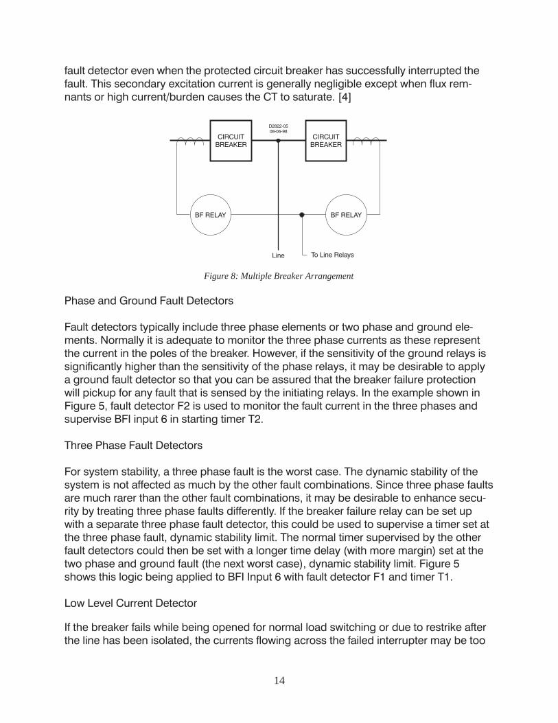
One additional caution is offered in the application of breaker failure fault detectors. Inring bus or breaker and a half applications, CTs from two breakers are often connectedin parallel. If the breaker failure relay is connected to these CTs as shown in Figure 8,low fault detector pickup settings should be used with caution. In this arrangement, theCT feeding the breaker failure relay fault detector can be energized on the secondaryside from the CT on the adjacent circuit breaker. This results in current flowing in the
14
fault detector even when the protected circuit breaker has successfully interrupted thefault. This secondary excitation current is generally negligible except when flux rem-nants or high current/burden causes the CT to saturate. [4]
Figure 8: Multiple Breaker Arrangement
Phase and Ground Fault Detectors
Fault detectors typically include three phase elements or two phase and ground ele-ments. Normally it is adequate to monitor the three phase currents as these representthe current in the poles of the breaker. However, if the sensitivity of the ground relays issignificantly higher than the sensitivity of the phase relays, it may be desirable to applya ground fault detector so that you can be assured that the breaker failure protectionwill pickup for any fault that is sensed by the initiating relays. In the example shown inFigure 5, fault detector F2 is used to monitor the fault current in the three phases andsupervise BFI input 6 in starting timer T2.
Three Phase Fault Detectors
For system stability, a three phase fault is the worst case. The dynamic stability of thesystem is not affected as much by the other fault combinations. Since three phase faultsare much rarer than the other fault combinations, it may be desirable to enhance secu-rity by treating three phase faults differently. If the breaker failure relay can be set upwith a separate three phase fault detector, this could be used to supervise a timer set atthe three phase fault, dynamic stability limit. The normal timer supervised by the otherfault detectors could then be set with a longer time delay (with more margin) set at thetwo phase and ground fault (the next worst case), dynamic stability limit. Figure 5shows this logic being applied to BFI Input 6 with fault detector F1 and timer T1.
Low Level Current Detector
If the breaker fails while being opened for normal load switching or due to restrike afterthe line has been isolated, the currents flowing across the failed interrupter may be too

15
low to reliably detect by conventional means. Numerical relays can use digital signalprocessing algorithms such as a moving average filter on the low level currents todiscern the line charging current from the random noise.
This type of fault detector would be supervised by a breaker status contact so that it isonly in service when the breaker is indicated to be open. Under these conditions, thefailed interrupter with the low level arcing would eventually be destroyed unless thebreaker is closed. After reclosing the breaker, if the line is still faulted, the failed breakercan be isolated by conventional breaker failure protection. If it is not, the failed breakercan be isolated by normal switching. In the example shown in Figure 5, this function isprovided by fault detector F3, timer T3 and output O3.
Logic Inputs
BFI and Other Inputs
The breaker failure relay needs at least one initiate input to indicate when the protectiverelays are attempting to trip the monitored breaker. In addition, as indicated earlier, itmay be necessary to provide a separate logic input for supervising breaker failuretripping without the use of the fault detectors.
As mentioned in the section discussing breaker failure protection system logic, addi-tional inputs are also usually provided to allow for breaker failure trip supervised bybreaker status instead of the fault detector. To enhance the reliability of this logic, it maybe desirable to use both �a� and �b� contacts with both contacts having to be in con-gruence to indicate breaker opening. The example shown in Figure 5 monitors both aand b contacts to start breaker arcing detection protection. If the two inputs are not incongruence, this is indicated by the alarm output.
Input Conditioning
Security of the BFI input is extremely important. A recognition timer can be used toeliminate false initiate signals due to noise and transients, while a debounce timer canbe used to fill in gaps due to contact bounce. In a numerical relay, these parameterscan be customized to obtain the optimum tradeoff between speed and security. Forexample, if there is a problem with AC coupling in the sensing circuits, the recognitiontimer can be set to greater than one half cycle to reject the half cycle rectified signalcoming from the opto isolator diodes.
Seal In of the BFI Signal
Some breaker failure relays provide the optional feature of sealing in the BFI input. Thisfeature is useful in applications where electromechanical relays require memory voltageto operate during a close in fault where the local voltage has collapsed to zero. Duringthe delayed clearing caused by the breaker failing, the memory voltage may expire and

16
cause the relay to drop out before backup tripping can be completed. This feature canalso serve to debounce the BFI signal if the relay does not include a contact condition-ing feature.
Seal in of the BFI signal should be used with caution since this feature can reduce thesecurity of the breaker failure protection system. In this case, the timer can only bestopped by the supervisory function (fault detector or breaker status contact). For ex-ample, if seal in of the BFI input being used with breaker status supervision is used, aspurious BFI input will result in a backup trip every time. In the event that it is used onan input with fault detector supervision, a misoperation may be prevented by the use ofa control timer. For this reason, it is recommended that BFI seal in not be applied tobreaker failure logic with breaker status supervision.
This is illustrated in the example in Figure 5. BFI input 6 that is connected to the linerelays is sealed in for the duration of the control timer by use of virtual output O10. BFIinput 7 that is connected to the transformer lockout relay is not sealed in. It should benoted that the seal in and/or control timer function must be coordinated such that theBFI input is released prior to an automatic reclose. This is generally not a problemunless the breaker failure protection system is applied to a circuit breaker using a highspeed reclose shot. An alternative to using the control timer to break the BFI seal in, theuser might use fault detector dropout.
Breaker Retrip
An additional security feature that is often provided in modern breaker failure relays isthe retrip function. This function sends an independent trip signal to the breaker if thebreaker failure relay is initiated. This feature can enhance security in two ways. If, forsome reason, the relays have tripped but there is a problem in the circuit such as withthe 94 (auxiliary tripping) relay that prevents the trip from being sent to the breaker, thebreaker failure relay will go ahead and trip the breaker instead of having to trip backup.The second way that this feature can enhance security is if the relay is inadvertentlyinitiated such as during testing. In this case it will trip the circuit breaker, stopping thebreaker failure relay from timing out and tripping backup. This feature is provided byoutput 5 in the example shown in Figure 5.

17
Figure 9: Trip Circuit Monitor
Monitoring the Trip Circuits and the Breaker
Trip Circuit Voltage and Continuity Monitor
A popular feature of many multifunction relays is the ability to monitor the trip circuit andalarm for loss of voltage (open fuse) or loss of continuity (open trip coil). Figure 9ashows a trip circuit monitor (TCM) sensing element (IN1) placed in parallel with thetripping output of the relay. Figure 9b shows a diagram of the logic.
When the breaker is closed, the trip bus, T, is at negative potential through the lowimpedance path of the trip coil. The TCM senses a logic 1. Figure 9c shows a timingdiagram of the operation of this logic. When a trip occurs, the trip bus is at positivepotential, the voltage across the TCM is shorted, and it senses a logic 0. When thebreaker opens, the 52a contact in series with the trip coil opens, the protective relaydrops out, the trip bus is at positive potential through the high impedance of the red

18
indicating light or the TCM sensing element, and the TCM continues to sense a logic 0.The breaker status input (IN4) in the logic diagram is used to block the function whilethe breaker and, therefore, the trip circuit is open. The timer is used to prevent an alarmoutput during the transition between closed and open.
In the example illustrated in Figure 5, each trip circuit of the breaker is monitored byinput 1, and input 2 respectively with timer T6. If either trip circuit has a problem, thealarm output is closed.
Figure 10: Trip Circuit Monitor with BFI Sensing
Figure 10 illustrates a problem that can occur when using this feature in conjunctionwith a breaker failure relay. If the breaker failure initiate sensing is connected directly tothe breaker�s trip bus as shown in Figure 10a, the equivalent circuit shown in Figure10b occurs. If the diode is not included in the circuit as shown, a voltage divider circuitwill be created between the BFI sensing and the TCM sensing when the 52a contact orthe trip coil is open. It should be noted that the placement of the diode in the example issuch that breaker failure will not be initated due to control switch trip (101T) or by theBF relay�s retrip output. Also, the 86 tripping contact is placed to the right of the diodesince it is assumed that one of the 86�s contacts will be directly connected to the �ini-tiate with breaker status supervision� input and that the 62X contact will be connectedto the �initiate with fault detector supervision� input.
In the example, a 62X BFI auxiliary relay is shown. In this case, the impedance of the62X coil will be small compared to the impedance of the TCM circuit so the TCM willalways be at logic 1. This will prevent the TCM logic from working, even if the trip coil isopen. In the case that a high impedance BFI sensing input is used, the TCM and theBFI impedances may be of similar magnitude, causing the voltage to be divided nearlyequally. This can result in spurious BFI signals to the breaker failure protection schemewhen the breaker is open. Normally, when redundant systems are used, each relaysystem will be on its own circuit and the BFI sensing for each relay system will be iso-lated from the tripping circuit, so this is not a problem.

19
Breaker Mechanism Monitoring
Traditionally, circuit breakers operating mechanisms were a very fail safe device. Forexample, the energy for interruption of the current in an oil interrupter is provided by thearc itself. Therefore, the mechanisms relied on stored energy (pneumatic, hydraulic, orspring charging motor) to close the breaker. Opening was provided by gravity withperhaps the assistance of an opening or accelerator spring. The opening spring wascharged by the closing stroke of the mechanism. If there was a problem with the operat-ing mechanism, the breaker could always be relied upon to trip at least once.
With the advent of air blast, and now SF6 breakers, the energy for opening and interrup-tion of the current is provided by external means. In the case of air blast breakers,stored air pressure. In the case of two presure SF6 breakers, stored gas pressure. In thecase of puffer style SF6 breakers, stored energy (pneumatic, hydraulic, or spring charg-ing motor) in the mechanism. Many of the puffer style breakers use power closed,power open mechanisms, or even spring closed, power open mechanisms instead ofthe traditional power closed, spring open mechanisms used in oil breakers. In the caseof puffer style SF6 breakers, besides providing dielectric strength, the SF6 gas providesdampening of the operating mechanism by the gas being forced through the puffernozzles. For this reason, the loss of SF6 density (temperature compensated pressure)can also disable the mechanism. The result is a somewhat less fail safe device.
Because of this, these types of breakers are often designed with monitoring systemsthat can warn when the breaker is no longer capable of tripping. Depending upon thephilosophy of the operating company, this logic can be set up to do one of three things.It can automatically trip out the breaker before total loss of gas pressure or storedenergy. It can be set to alarm only and rely upon the breaker failure protection systemto trip should a fault occur before the breaker can be isolated and taken out of service.Or it can even be set to trip the breaker failure lockout to isolate the breaker. This lastresponse may be considered extreme since an SF6 breaker with zero pressure stillgenerally has adequate dielectric strength to withstand normal system voltage.
Use of Monitoring in Breaker Failure Logic
In the example shown in Figure 5, output 4 is used to indicate that the breaker is notcapable of tripping. This logic is true if both trip circuits are bad as indicated by the tripcircuit monitoring function, or the breaker monitoring function indicates that the breakermechanism has been disabled as indicated by a contact connected to input 3.
Under the situation where it is known that the breaker will not trip, it may be desirable totrip backup without waiting for the breaker failure time delay. In the example illustratedin Figure 5, output 4 is used for tripping of backup with bypass of the breaker failuretimers through output 2.

20
Pole Disagreement Protection
Pole disagreement occurs when one pole becomes stuck closed or open resulting in allthree poles of the breaker not being in the same state. On a networked system or ringbus application, this condition can be difficult to detect and can result in tripping ofground and negative sequence relays throughout the system due to the series unbal-ance. This type of protection is usually applied to circuit breakers that have indepen-dent pole operators. A breaker with independent pole operators has a separate operat-ing mechanism on each pole of the breaker.
Figure 11: Example, Pole Disagreement Logic
Pole disagreement for this type of breaker can be relatively reliably detected usingmechanism auxiliary contact logic. For example, the user could connect contacts asshown in Figure 11. In the example shown in Figure 5, Input 4 and 5 would providesensing and Timer T5 would ride through the slight variation in timing of the variouscontacts. The example logic diagram would be modified to connect the timer output T5to the logic expression for breaker retrip so that the breaker will be opened if bothinputs are true at the same time.
During a closing operation, the pole disagreement would be caused by a pole beingstuck open and the disagreement condition would be removed by breaker opening.During a tripping operation, disagreement would be caused by a pole being stuckclosed. Normal breaker failure protection will cover this condition during a fault. How-ever, during a switching operation, the breaker failure protection may not be initiated.

21
Thus, this condition might be used to alarm so that corrective action could be taken. Itcould even be used to trip backup to isolate the breaker with the pole stuck closed.
Single pole operator breakers are sometimes used in single pole tripping applicationswhere only the faulted phase is tripped during a single phase fault. Pole disagreementprotection for this application is beyond the scope of this discussion.
For standard circuit breakers with three pole operators, pole disagreement can occurdue to failures in the interpole linkages. Pole disagreement for this type of breaker canbe detected using sensitive current detectors to measure the current in each pole of thebreaker. The low level current detector feature mentioned earlier in the paper providesthis protection when the breaker is supposed to be in an open state.
For pole disagreement protection when the breaker is in a closed state, pole disagree-ment is detected if the current level in one pole is significantly different than the currentlevel in the other two. The difference criteria must be a ratio of current in each pole tosome average of the current in all poles so that it automatically adjusts its sensitivity forcircuit loading. Additionally, it is necessary to reject current unbalance caused by sys-tem disturbances. This is done by adding a time delay longer than the typical faultclearing time for the surrounding circuits. Since pole disagreement while the breaker isclosed will most likely be caused by a pole not closing, additional security can beprovided by only enabling the protection using a control timer that enables it for a shortperiod of time after a closing operation.
BACKUP TRIPPING
Once a breaker failure system has been applied, it is necessary to look at the backuptripping logic that needs to be implemented. This will differ with bus configuration,system requirements, operating practices and the amount of risk that the system opera-tor is willing to take.
Lockout Relay
Breaker failure protection systems usually use a lockout relay (device 86) to handle thebackup tripping chores. Lockout relays are ideally suited for this purpose because theycan have many decks that can provide for keying transfer trip and tripping and prevent-ing automatic or manual reclosing of the many adjacent breakers required to be trippedwhen a breaker fails. The adjacent breakers cannot be closed until the failed breakerhas been isolated and the lockout relay reset.
It is not necessary to apply a separate lockout relay for each breaker if all of the samebreakers on the bus are to be tripped for any one breaker failure. If this is not the caseor if transfer trip systems are used to trip the remote breaker on the particular line withthe failed breaker, it is usually desirable to apply separate lockout relays. This is gener-ally the case in a straight bus arrangement. In more complex bus arrangements, a

22
lockout relay for each breaker may need to be applied so that backup tripping logic canbe applied specifically to each breaker.
Transfer Trip or Remote Backup?
In nearly every case of a networked system application, at least one of the adjacentbreakers that must be opened is at a remote location. Is a transfer trip system required?In the case where stability is a concern, delayed tripping cannot be tolerated, so a pilotsystem will most likely be applied for line protection. If this is the case, the additionalcost of a transfer trip system across the pilot channel is usually minimal, so completelocal backup can be achieved.
In the case where stability is not a concern, other considerations apply to answeringthis question. Many configurations are possible but the following examples illustrate theconcepts that should be applied.
Straight Bus Applications
In the example system illustrated in Figure 1, let us consider breaker failure protectionfor John Substation. Under normal situations, the line breakers J1, J2, and J3 will becalled upon to trip: for faults on their respective line; for faults on the bus; and for faultswithin the transformer zone of protection. For a transformer fault, the breakers aretripped, the MOD (motor operated disconnect) is opened, and the breakers automati-cally reclosed.
Let us consider each of these situations in turn. If breaker J3 fails, breaker J1 and J2 aretripped and locked out, removing those sources to all zones protected by the failedbreaker. The only breaker that must be considered in the contingency analysis is theremote breaker SZ.
� If the fault is on line JZ, the relays at SZ will trip normally.
� If the fault is on the bus, the relays at SZ can easily detect it in zone 2. Sensitivity isnot a concern. The addition of transfer trip can provide faster clearing and canprevent the automatic reclose of breaker SZ into the bus fault.
� If the fault is in the transformer zone, sensitivity is a concern because the relays atSZ cannot be counted on to see the fault. In this case, the addition of transfer tripshould also be considered. An alternative is reliance upon the so-called �sacrificiallamb�. In this case, the MOD is started at the same time that the breakers aretripped. If one of the breakers does not trip, the MOD will flash over, causing a busfault that can be detected remotely. The clearing will be slow and damage consid-erable. In applying this protection concept, the protection engineer is relying onprobabilities to justify the savings of not applying a transfer trip system. Transformerfaults are relatively rare and breaker failure operations are rarer still.
23
Ring Bus Applications
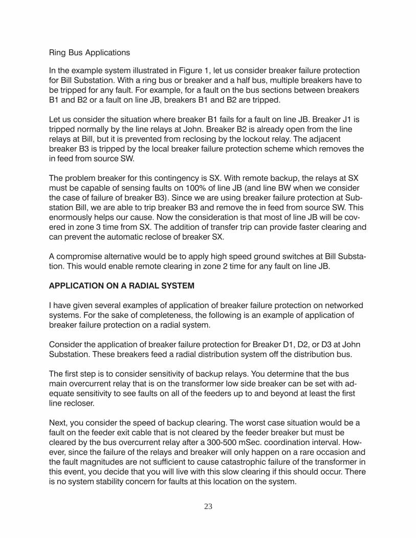
In the example system illustrated in Figure 1, let us consider breaker failure protectionfor Bill Substation. With a ring bus or breaker and a half bus, multiple breakers have tobe tripped for any fault. For example, for a fault on the bus sections between breakersB1 and B2 or a fault on line JB, breakers B1 and B2 are tripped.
Let us consider the situation where breaker B1 fails for a fault on line JB. Breaker J1 istripped normally by the line relays at John. Breaker B2 is already open from the linerelays at Bill, but it is prevented from reclosing by the lockout relay. The adjacentbreaker B3 is tripped by the local breaker failure protection scheme which removes thein feed from source SW.
The problem breaker for this contingency is SX. With remote backup, the relays at SXmust be capable of sensing faults on 100% of line JB (and line BW when we considerthe case of failure of breaker B3). Since we are using breaker failure protection at Sub-station Bill, we are able to trip breaker B3 and remove the in feed from source SW. Thisenormously helps our cause. Now the consideration is that most of line JB will be cov-ered in zone 3 time from SX. The addition of transfer trip can provide faster clearing andcan prevent the automatic reclose of breaker SX.
A compromise alternative would be to apply high speed ground switches at Bill Substa-tion. This would enable remote clearing in zone 2 time for any fault on line JB.
APPLICATION ON A RADIAL SYSTEM
I have given several examples of application of breaker failure protection on networkedsystems. For the sake of completeness, the following is an example of application ofbreaker failure protection on a radial system.
Consider the application of breaker failure protection for Breaker D1, D2, or D3 at JohnSubstation. These breakers feed a radial distribution system off the distribution bus.
The first step is to consider sensitivity of backup relays. You determine that the busmain overcurrent relay that is on the transformer low side breaker can be set with ad-equate sensitivity to see faults on all of the feeders up to and beyond at least the firstline recloser.
Next, you consider the speed of backup clearing. The worst case situation would be afault on the feeder exit cable that is not cleared by the feeder breaker but must becleared by the bus overcurrent relay after a 300-500 mSec. coordination interval. How-ever, since the failure of the relays and breaker will only happen on a rare occasion andthe fault magnitudes are not sufficient to cause catastrophic failure of the transformer inthis event, you decide that you will live with this slow clearing if this should occur. Thereis no system stability concern for faults at this location on the system.

24
After the forgoing analysis, you determine that you will not apply a dedicated breakerfailure protection system in this application due to the added cost and complexity.However, you are considering using a multifunction overcurrent protection system thatincludes a breaker failure function block. How can the protection be improved by usingthis feature?
From the preceding discussion, we know that the failure of the relay is a separate con-tingency from failure of the circuit breaker. If we can detect the difference between thesetwo contingencies, it is not necessary to take the same corrective action for both fail-ures. For instance, if a feeder relay has failed, the bus overcurrent relay can be pro-grammed to attempt to trip that feeder before tripping off the whole bus. This wouldreduce the outage to only the feeder with the failed relay as would happen if both fail-ures are treated the same. On the other hand, if the feeder breaker fails, the bus breakercan be directly tripped in breaker failure time instead of having to wait for the traditionalcoordination interval of the bus overcurrent relay. This would result in faster clearing ofthe fault�reducing equipment damage and through fault duty on the transformer.
SUMMARY
Contingency analysis is the most difficult job of the protection engineer. Careful analysisof all contingencies under all possible system conditions is necessary if reliance ismade on remote backup with coordinated relays. Application of dedicated breakerfailure protection systems can greatly simplify this task.
When determining if breaker failure relaying should be applied, sensitivity and speedare the primary concerns. Breaker failure protection systems can improve both of theseat the expense of greater cost and complexity in the relaying systems.
The design of breaker failure protection systems is generally biased toward security.Modern breaker failure relays have a great number of features to enhance security andimprove protection over the use of discrete fault detector and timer relays.
To emphasize the point of how difficult the job of contingency analysis can be, I wouldlike to leave you with an example of how things can bite you in the behind even if youhave done a thorough job of it.
Consider the protective relaying system where you have applied complete redundancy.Your substation protection system has redundant instrument transformers connected toredundant relay systems, feeding redundant trip circuits that are fed by redundantbattery supplies. You fully test each and every system including trip testing each systemindividually so that you prove each and every device trips the breaker. You turn thesubstation over to the operator and it is put in service.
The first time there is a fault on the system, the breaker fails to trip. Where did you gowrong? In a breaker with dual trip coils, any one coil will trip the breaker. When an

25
actual fault occurred, the redundant systems responded simultaneously and energizedboth coils simultaneously. If one of the coils was inadvertently put in upside down, themagnetic fields canceled and the trip latch was not released. This situation only occursduring a fault because such non-critical items as the control switch are typically in-cluded only in the one of the trip coil circuits. The breaker operated fine under normalsystem switching. Unless your trip test procedure calls for testing both trip circuitssimultaneously at least once, this could happen.
WORKS CITED
[1] Blackburn, J. Lewis, Protective Relaying, Principles and Applications, 2nd Edi-tion, New York: Marcel Dekker, Inc., 1998.
[2] Daume, Jon F., "Summer of our Disconnects", 1996 Western SystemsCoordinating Council Power System Disturbances, July 2,3 and August 10, 1996,1997 Western Protective Relay Conference
[3] Lerley, P., Kanuchok, J., and Ransick, J., "Flexible Breaker Failure and ProtectionRelaying", Protective Relaying Committee Meeting No. 69, Electric Council ofNew England
[4] Ibrahim, Mohamed A., "St. Lawrence 230 kV Substation Disturbance of March 6,1996", 1998 Georgia Institute of Technology Protective Relaying Conference
[5] Elmore, Walter A., ed., ABB Inc., Protective Relaying, Theory and Applications,New York: ABB/Marcel Dekker, 1994
[6] Dalke, G., Stringer, N., and Brogan, J., "How Can Current Dropout Affect BreakerFailure Timing Margins?," 1996 Texas A&M Conference for Protective RelayEngineers
Michael Thompson served nearly 15 years at Central Illinois Public Service Company,where he worked in distribution and substation field operations before taking responsi-bility for system protection engineering. He received a BS, Magna Cum Laude, fromBradley University in 1981 and an MBA from Eastern Illinois University in 1991. Duringhis years at Bradley University, Mike was involved in the cooperative education programand worked in electrical engineering and maintenance at a large steel and wire prod-ucts mill. Mike joined Basler Electric's Protection and Control Marketing Department in1995 as a Product Manager, then was promoted to Senior Product and Market Managerfor the Protection and Control product line in 2000. Mr. Thompson is a member of IEEE.

Basler Electric HeadquartersRoute 143, Box 269,Highland Illinois USA 62249Phone +1 618.654.2341Fax +1 618.654.2351
Basler Electric InternationalP.A.E. Les Pins, 67319 WasselonneCedex FRANCEPhone +33 3.88.87.1010Fax +33 3.88.87.0808
If you have any questions or needadditional information, please contact
Basler Electric Company.Our web site is located at:
http://www.basler.come-mail: [email protected]
Related Documents