1 BrDR Visual Reference Guide to Using BrDR 6.8.0 Published September, 2016

Welcome message from author
This document is posted to help you gain knowledge. Please leave a comment to let me know what you think about it! Share it to your friends and learn new things together.
Transcript
1
BrDR Visual Reference
Guide to Using BrDR 6.8.0
Published September, 2016
AASHTOWare Bridge Design and Rating Visual Reference
2
Introduction to the Visual Guide to BrDR
Manual Philosophy
The philosophy used behind this manual is one of progression. Every
sentence, paragraph and chapter is written upon the knowledge of what was gained previously.
Pictures say a thousand words
This manual relies on pictorial representations of each procedure you should
use in BrDR. Each procedure will be shown once and referred back to. The conventions used in the representations are listed below.
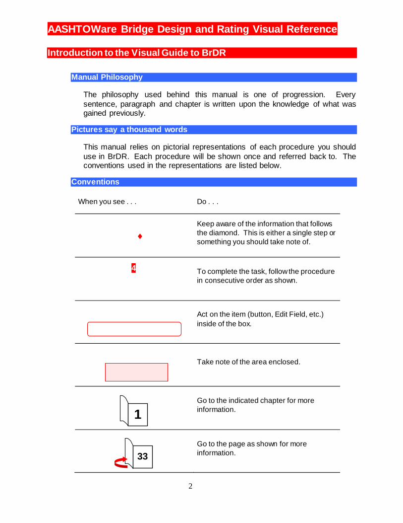
Conventions
When you see . . . Do . . .
Keep aware of the information that follows
the diamond. This is either a single step or
something you should take note of.
4
To complete the task, follow the procedure
in consecutive order as shown.
Act on the item (button, Edit Field, etc.)
inside of the box.
Take note of the area enclosed.
Go to the indicated chapter for more
information.
Go to the page as shown for more
information. 33
1
AASHTOWare Bridge Design and Rating Visual Reference
3
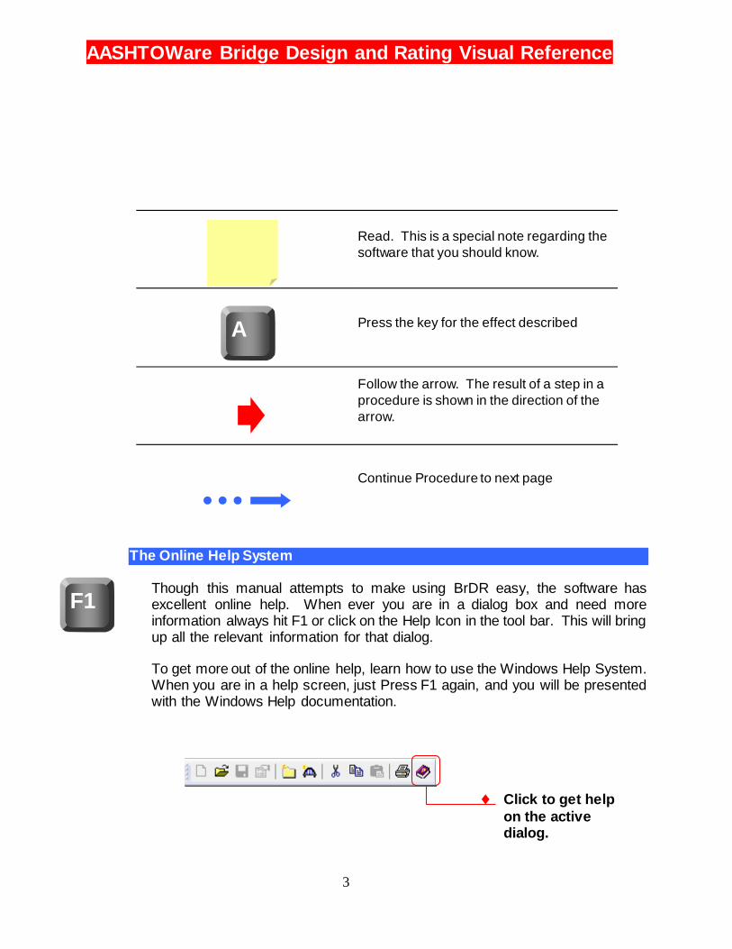
Read. This is a special note regarding the
software that you should know.
Press the key for the effect described
Follow the arrow. The result of a step in a
procedure is shown in the direction of the
arrow.
Continue Procedure to next page
The Online Help System
Though this manual attempts to make using BrDR easy, the software has excellent online help. When ever you are in a dialog box and need more information always hit F1 or click on the Help Icon in the tool bar. This will bring up all the relevant information for that dialog.
To get more out of the online help, learn how to use the Windows Help System. When you are in a help screen, just Press F1 again, and you will be presented with the Windows Help documentation.
F1
A
Click to get help
on the active dialog.
AASHTOWare Bridge Design and Rating Visual Reference
4
Getting Started AASHTOWare Bridge Design and Rating Overview
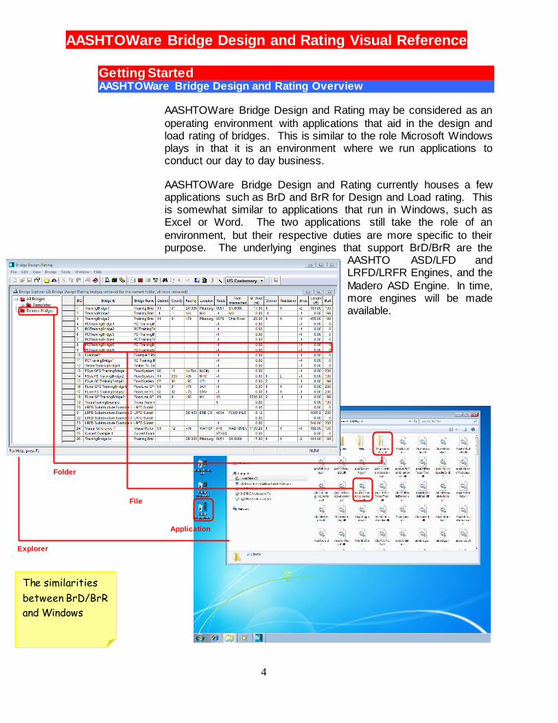
AASHTOWare Bridge Design and Rating may be considered as an
operating environment with applications that aid in the design and load rating of bridges. This is similar to the role Microsoft Windows plays in that it is an environment where we run applications to conduct our day to day business.
AASHTOWare Bridge Design and Rating currently houses a few applications such as BrD and BrR for Design and Load rating. This is somewhat similar to applications that run in Windows, such as Excel or Word. The two applications still take the role of an
environment, but their respective duties are more specific to their purpose. The underlying engines that support BrD/BrR are the
AASHTO ASD/LFD and LRFD/LRFR Engines, and the
Madero ASD Engine. In time, more engines will be made available.
The similarities
between BrD/BrR
and Windows
Background
Application
File
Explorer
Folder

AASHTOWare Bridge Design and Rating Visual Reference
5
BrR
BrR is used for bridge superstructure and culvert load rating, featuring graphical tools to
speed preparation of the data and application of the results. Using the AASHTO LFR/LRFR as its analytical engine for load
factor rating, BrR provides an integrated database where rating inputs and outputs can readily be stored, reviewed, and reused.
BrD
BrD is currently a bridge superstructure, substructure, and culvert design-review software product using the AASHTO Load and Resistance Factor Design
(LRFD) Bridge Specifications. BrD employs the same database and graphical user interface as BrR, and shares much of the
same source code. Development of both products began in 1997. The AASHTO LRFD Engine provides the system's structural analysis and
specification checking engine.
AASHTOWare Bridge Design and Rating Visual Reference
6
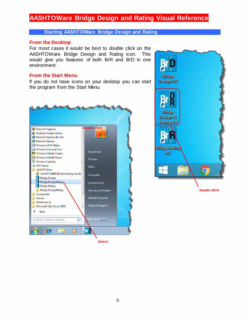
Starting AASHTOWare Bridge Design and Rating
From the Desktop
For most cases it would be best to double click on the
AASHTOWare Bridge Design and Rating icon. This would give you features of both BrR and BrD in one environment.
From the Start Menu
If you do not have icons on your desktop you can start the program from the Start Menu.
Double dlick
Double click
Select

AASHTOWare Bridge Design and Rating Visual Reference
7
Entering User Name and Password
The AASHTOWare Bridge Design and Rating Logo Window will pop up. Here you will need to enter your user name and password in the
provided fields.
o Connecting to the database
At times, the Data Source field will be empty. This means the database is not
connected. You will need to connect to the database. To do this, click on the button with the three periods. Then . . .
2 Click to connect
to database
1 Select one of
the databases
prov ided
2 Click OK
1 Enter username
and password

AASHTOWare Bridge Design and Rating Visual Reference
8
o AASHTOWare Bridge Design and Rating Basics
AASHTOWare Bridge Design and Rating Environment Tour
Bridge
Explorer
Bridge
Workspace
Standard
Toolbar
Bridge
Workspace
Toolbar
The
Explorers
Launching
Toolbar
Bridge
Explorer
Toolbar
BrD
Substructure
Toolbar

AASHTOWare Bridge Design and Rating Visual Reference
9
AASHTOWare Bridge Design and Rating Environment
The Bridge
Explorer is
designed to work
like the Windows
Explorer
Bridge list
corresponding
to the selected
folder
Bridge Explorer tree

AASHTOWare Bridge Design and Rating Visual Reference
10
Bridge Explorer Window
Sorting the Bridge List
Once you select a folder to find a bridge, you may sort the corresponding bridge list to make the search easier. Sorting the bridge list requires double clicking on a column heading. The first time you do this, it will sort in an ascending order. Double clicking
again, will result in a descending sort. For example, I am looking for bridge 24 on I-76 in Waitsfield.
1 Double
click column
heading to
sort the bridge
ID in
ascending
order
2 Double
click
column
heading to
sort
location in
ascending
order
3 Select
bridge from list
AASHTOWare Bridge Design and Rating Visual Reference
11
The result is that both the Bridge ID number and the Location are sorted in ascending order. At this point I look down the list in the location column for Waitsfield, then I look over at the Bridge ID until
I find bridge 24 (see where the cursor is pointing in the third screen shot above).
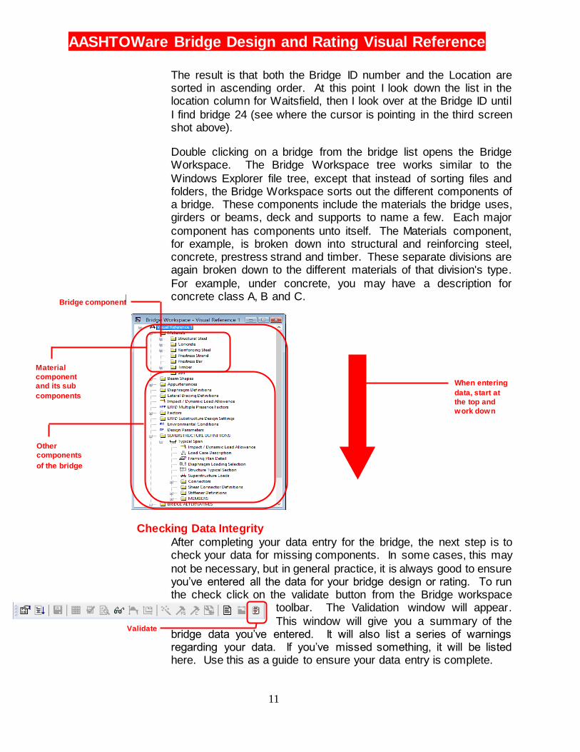
Double clicking on a bridge from the bridge list opens the Bridge Workspace. The Bridge Workspace tree works similar to the
Windows Explorer file tree, except that instead of sorting files and folders, the Bridge Workspace sorts out the different components of a bridge. These components include the materials the bridge uses, girders or beams, deck and supports to name a few. Each major
component has components unto itself. The Materials component, for example, is broken down into structural and reinforcing steel, concrete, prestress strand and timber. These separate divisions are again broken down to the different materials of that division's type.
For example, under concrete, you may have a description for concrete class A, B and C.
Checking Data Integrity
After completing your data entry for the bridge, the next step is to check your data for missing components. In some cases, this may
not be necessary, but in general practice, it is always good to ensure you’ve entered all the data for your bridge design or rating. To run the check click on the validate button from the Bridge workspace
toolbar. The Validation window will appear.
This window will give you a summary of the bridge data you’ve entered. It will also list a series of warnings regarding your data. If you’ve missed something, it will be listed here. Use this as a guide to ensure your data entry is complete.
Bridge component
When entering
data, start at
the top and
work down
Material
component
and its sub
components
Other
components
of the bridge
Validate
AASHTOWare Bridge Design and Rating Visual Reference
12
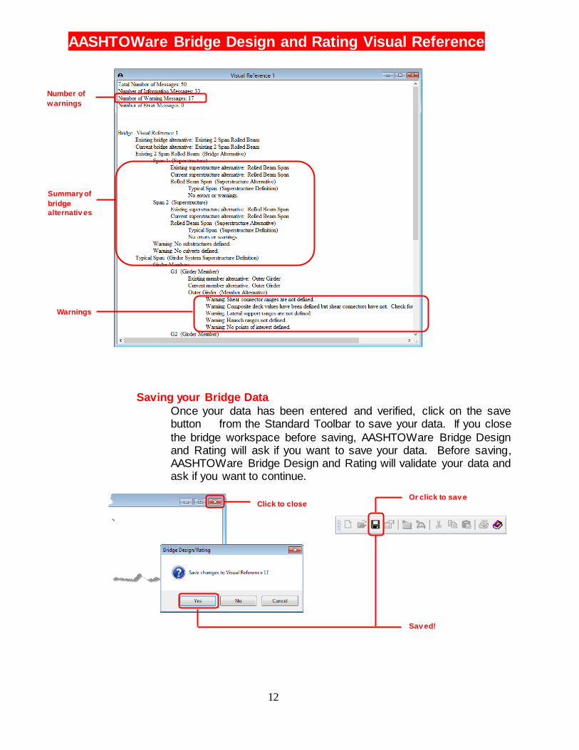
Saving your Bridge Data
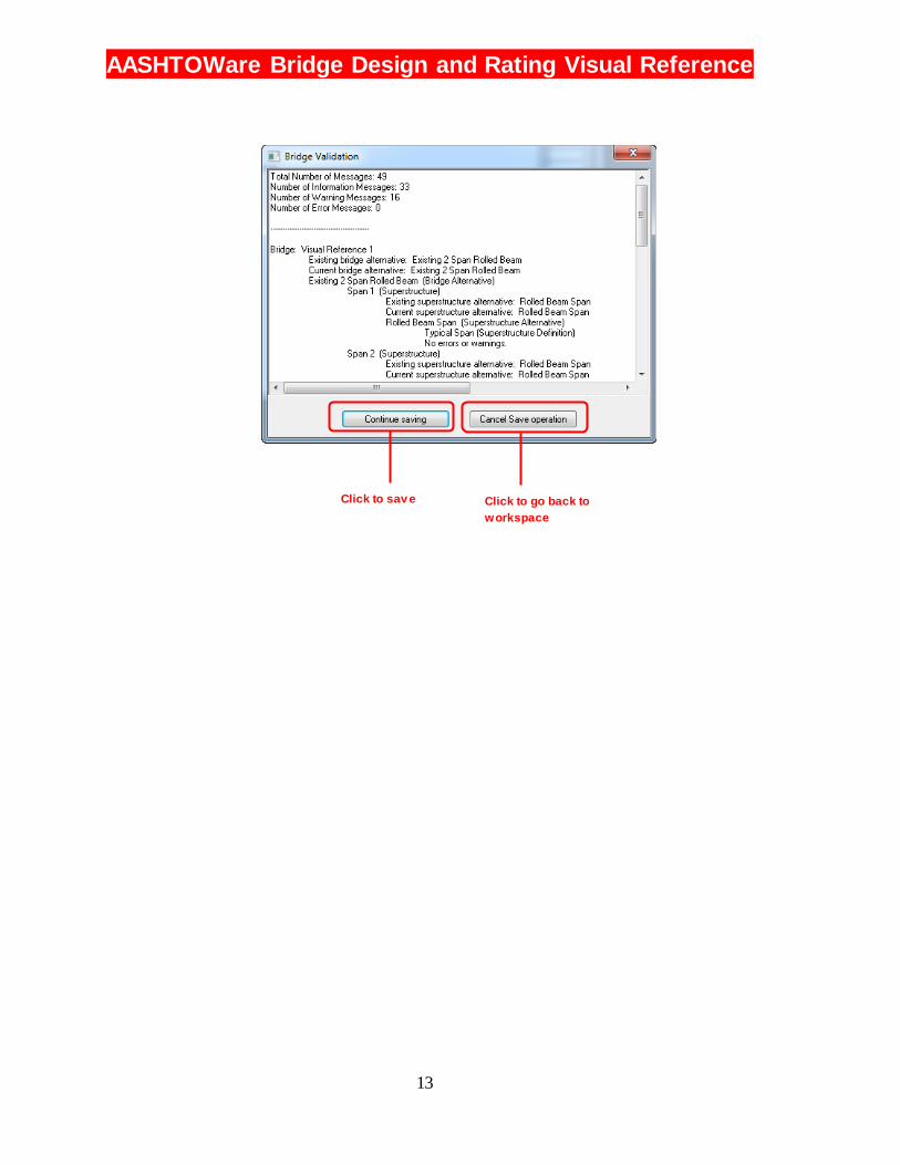
Once your data has been entered and verified, click on the save button from the Standard Toolbar to save your data. If you close
the bridge workspace before saving, AASHTOWare Bridge Design and Rating will ask if you want to save your data. Before saving, AASHTOWare Bridge Design and Rating will validate your data and ask if you want to continue.
Number of
warnings
Summary of
bridge
alternativ es
Warnings
Sav ed!
Or click to sav e Click to close
AASHTOWare Bridge Design and Rating Visual Reference
13
Click to sav e Click to go back to
workspace
AASHTOWare Bridge Design and Rating Visual Reference
14
Starting a new Bridge Prerequisites:
Completing Chapter 1, Getting Started
Project Description
The bridge selected for this exercise is called Visual Reference 1 carrying I-76 over the Mad River. The bridge was approved for construction in 1938. It is a two simple span steel structure with each span being 84’. Each span was
constructed with 36 inch deep wide flange steel rolled sections (36 WF 250) 83’-3” in length. At the pier, a joint was constructed in the deck. The following data shall be entered into BrDR:
The units for this example will be in English.
Materials:
Structural Steel: Unknown from 1938 to 1939
Concrete: From Plans, Concrete Class “A” assume this was 3500 psi
Reinforcing Steel: Unknown from 1938 to 1939
Members:
Rolled Beam: 36WF250
Other items:
The deck is 7” thick concrete – no haunches over beams
The bridge has concrete railing.
Bridge Layout: See figure

AASHTOWare Bridge Design and Rating Visual Reference
15

AASHTOWare Bridge Design and Rating Visual Reference
16
Starting BrDR and Opening Bridge Data
Navigating the Folders
First step is to start BrDR and open the bridge file. This requires
navigating through the directories until you get to the bridge file.
Selecting the Bridge File
At this point, the list of bridges displayed in the right pane of the
Bridge Explorer should be similar to:
1
AASHTOWare Bridge Design and Rating Visual Reference
17
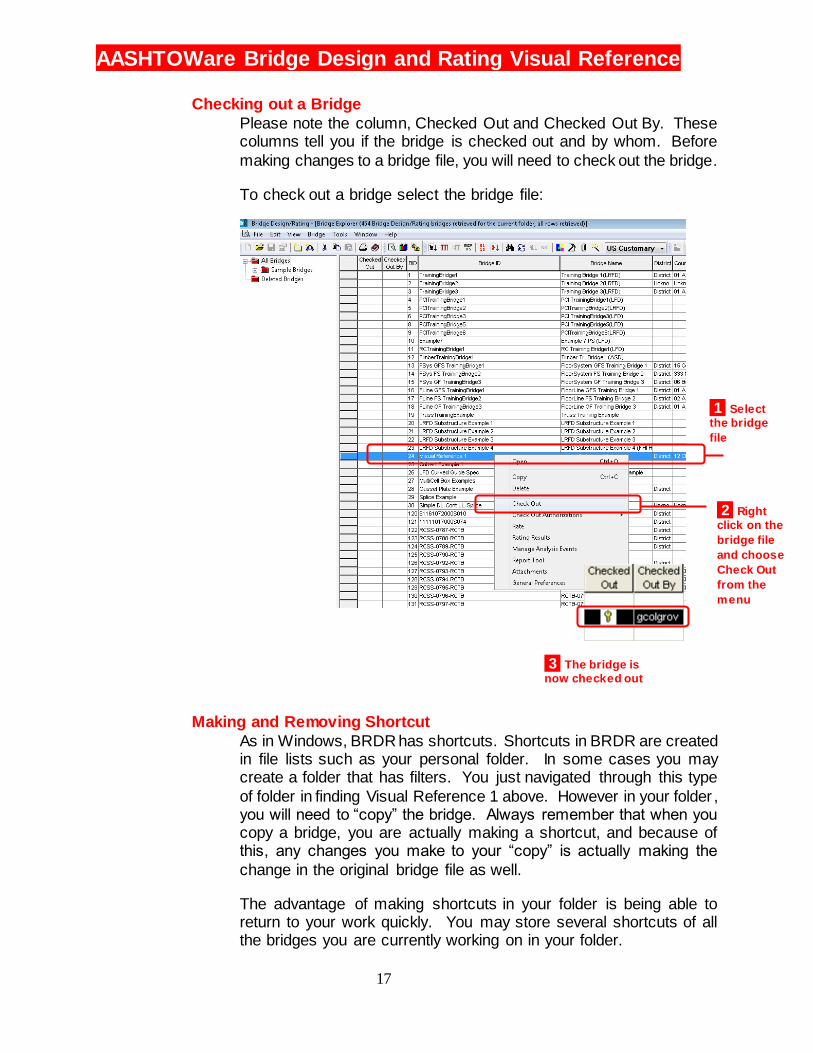
Checking out a Bridge
Please note the column, Checked Out and Checked Out By. These columns tell you if the bridge is checked out and by whom. Before
making changes to a bridge file, you will need to check out the bridge.
To check out a bridge select the bridge file:
Making and Removing Shortcut
As in Windows, BRDR has shortcuts. Shortcuts in BRDR are created in file lists such as your personal folder. In some cases you may create a folder that has filters. You just navigated through this type
of folder in finding Visual Reference 1 above. However in your folder , you will need to “copy” the bridge. Always remember that when you copy a bridge, you are actually making a shortcut, and because of this, any changes you make to your “copy” is actually making the
change in the original bridge file as well.
The advantage of making shortcuts in your folder is being able to return to your work quickly. You may store several shortcuts of all the bridges you are currently working on in your folder.
1 Select
the bridge
file
2 Right
click on the
bridge file
and choose
Check Out
from the
menu
3 The bridge is
now checked out
AASHTOWare Bridge Design and Rating Visual Reference
18
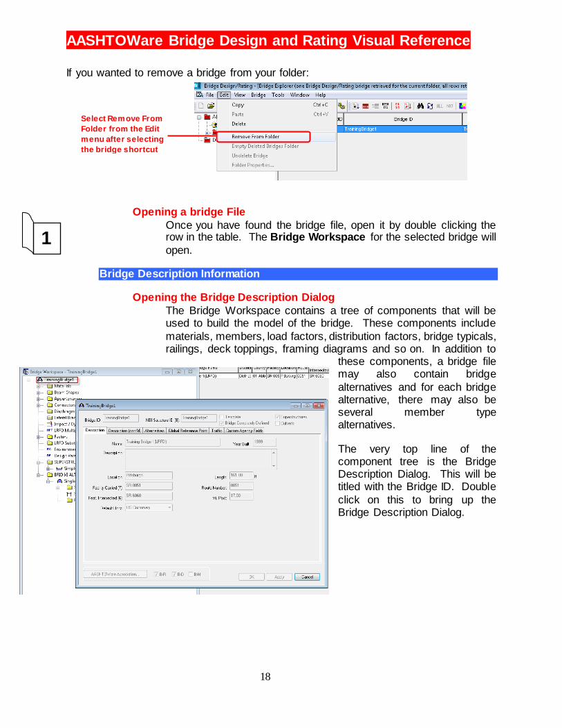
If you wanted to remove a bridge from your folder:
Opening a bridge File
Once you have found the bridge file, open it by double clicking the row in the table. The Bridge Workspace for the selected bridge will
open.
Bridge Description Information
Opening the Bridge Description Dialog
The Bridge Workspace contains a tree of components that will be used to build the model of the bridge. These components include
materials, members, load factors, distribution factors, bridge typicals, railings, deck toppings, framing diagrams and so on. In addition to
these components, a bridge file may also contain bridge
alternatives and for each bridge alternative, there may also be several member type alternatives.
The very top line of the component tree is the Bridge Description Dialog. This will be titled with the Bridge ID. Double
click on this to bring up the Bridge Description Dialog.
1
Select Remove From
Folder from the Edit
menu after selecting
the bridge shortcut

AASHTOWare Bridge Design and Rating Visual Reference
19
Bridge Description Information
The following is a brief description of the Information found in the Bridge Description Dialog. Most of the information you will see in this table has been filled out in advance. However, the data should be reviewed and modified as required.
Bridge ID:
Enter the bridge identification number assigned to the bridge. This must be unique within the system.
NBI Structure ID:
Enter the National Bridge Inventory (NBI) structure identification number assigned to the bridge. This value corresponds with Item 8 – Structure Number in the Federal Highway Administration’s Recording and Coding Guide for the Structure Inventory and
Appraisal of the Nation’s Bridges (December 1988 and December 1995 Editions). This must be unique within the system. See Bridge Inspection Manual Item 8 for more information.
AASHTOWare Bridge Design and Rating Visual Reference
20
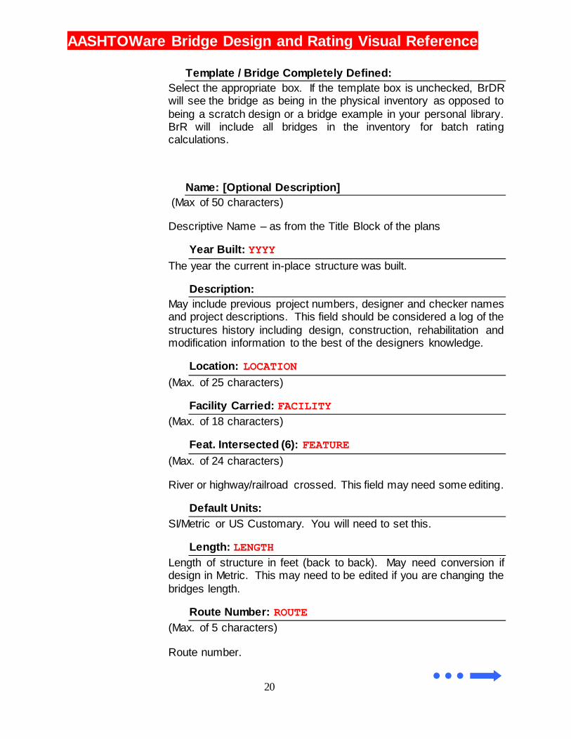
Template / Bridge Completely Defined:
Select the appropriate box. If the template box is unchecked, BrDR will see the bridge as being in the physical inventory as opposed to
being a scratch design or a bridge example in your personal library. BrR will include all bridges in the inventory for batch rating calculations.
Name: [Optional Description]
(Max of 50 characters)
Descriptive Name – as from the Title Block of the plans
Year Built: YYYY
The year the current in-place structure was built.
Description:
May include previous project numbers, designer and checker names and project descriptions. This field should be considered a log of the
structures history including design, construction, rehabilitation and modification information to the best of the designers knowledge.
Location: LOCATION
(Max. of 25 characters)
Facility Carried: FACILITY
(Max. of 18 characters)
Feat. Intersected (6): FEATURE
(Max. of 24 characters)
River or highway/railroad crossed. This field may need some editing.
Default Units:
SI/Metric or US Customary. You will need to set this.
Length: LENGTH
Length of structure in feet (back to back). May need conversion if design in Metric. This may need to be edited if you are changing the
bridges length.
Route Number: ROUTE
(Max. of 5 characters)
Route number.
AASHTOWare Bridge Design and Rating Visual Reference
21
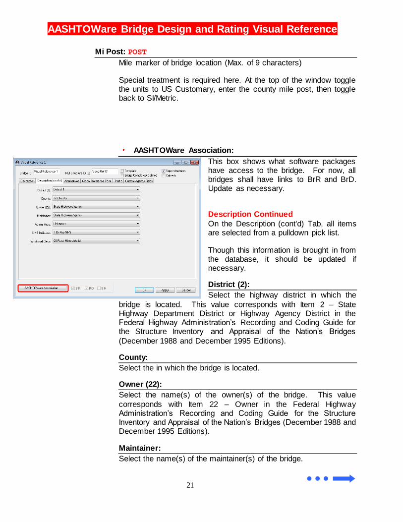
Mi Post: POST
Mile marker of bridge location (Max. of 9 characters)
Special treatment is required here. At the top of the window toggle the units to US Customary, enter the county mile post, then toggle back to SI/Metric.
AASHTOWare Association:
This box shows what software packages have access to the bridge. For now, all bridges shall have links to BrR and BrD. Update as necessary.
Description Continued
On the Description (cont'd) Tab, all items are selected from a pulldown pick list.
Though this information is brought in from the database, it should be updated if necessary.
District (2):
Select the highway district in which the
bridge is located. This value corresponds with Item 2 – State Highway Department District or Highway Agency District in the Federal Highway Administration’s Recording and Coding Guide for the Structure Inventory and Appraisal of the Nation’s Bridges
(December 1988 and December 1995 Editions).
County:
Select the in which the bridge is located.
Owner (22):
Select the name(s) of the owner(s) of the bridge. This value
corresponds with Item 22 – Owner in the Federal Highway Administration’s Recording and Coding Guide for the Structure Inventory and Appraisal of the Nation’s Bridges (December 1988 and December 1995 Editions).
Maintainer:
Select the name(s) of the maintainer(s) of the bridge.

AASHTOWare Bridge Design and Rating Visual Reference
22
Admin. Area:
Select the administrative area for the bridge.
NHS Indicator:
Select the National Highway System (NHS) indicator for the bridge.
Functional Class:
Select the functional class of the bridge.
If any changes needed to be made in the Bridge Description Dialog, the data needs to be updated. This is done by clicking on the Apply
button. You may also click on the OK button. This will apply the changes as well as close the dialog box. Pressing the cancel button
will close the dialog box while removing all changes you made. This is true for all dialog
boxes in BrDR.
Entering Bridge Data
At this point the bridge information data has been updated to reflect in field conditions. Now we need to enter the materials, the bridge members, load factors and other required information to run an analysis. As stated in chapter
1, the data should be entered in the order listed in the Bridge Workspace. This requires us to start with materials.
Materials
As stated in earlier in this chapter, we have steel members made
somewhere around 1938 to 1939. The concrete used was Class “A” concrete, again from 1939. In this case, I have decided to assume the strength of the concrete is 3500 psi. The reinforcing steel used was also from the period.
Enter
Accept
changes
and close
dialog box
Accept
changes
and keep
working
Reject
changes and
close dialog
box
In all dialog boxes,
pressing Enter w ill
engage the button
that is outlined. In
this case it w ill
activate ‘OK’

AASHTOWare Bridge Design and Rating Visual Reference
23
With this data we go to BrDR to define these materials. First we work with the Steel.
2 Double
click to enter
steel material
1 Click to
expand
material list
3 Click Copy
from Library to get
steel material
5 Results
4 Doubleclick the
appropriate material,
in this case 1936 to
1963 steel
AASHTOWare Bridge Design and Rating Visual Reference
24
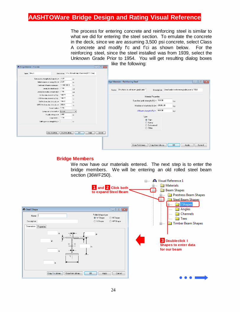
The process for entering concrete and reinforcing steel is similar to what we did for entering the steel section. To emulate the concrete in the deck, since we are assuming 3,500 psi concrete, select Class
A concrete and modify f'c and f’ci as shown below. For the reinforcing steel, since the steel installed was from 1939, select the Unknown Grade Prior to 1954. You will get resulting dialog boxes
like the following:
Bridge Members
We now have our materials entered. The next step is to enter the bridge members. We will be entering an old rolled steel beam section (36WF250).
3 Doubleclick I
Shapes to enter data
for our beam
1 and 2 Click both
to expand Steel Beam
AASHTOWare Bridge Design and Rating Visual Reference
25
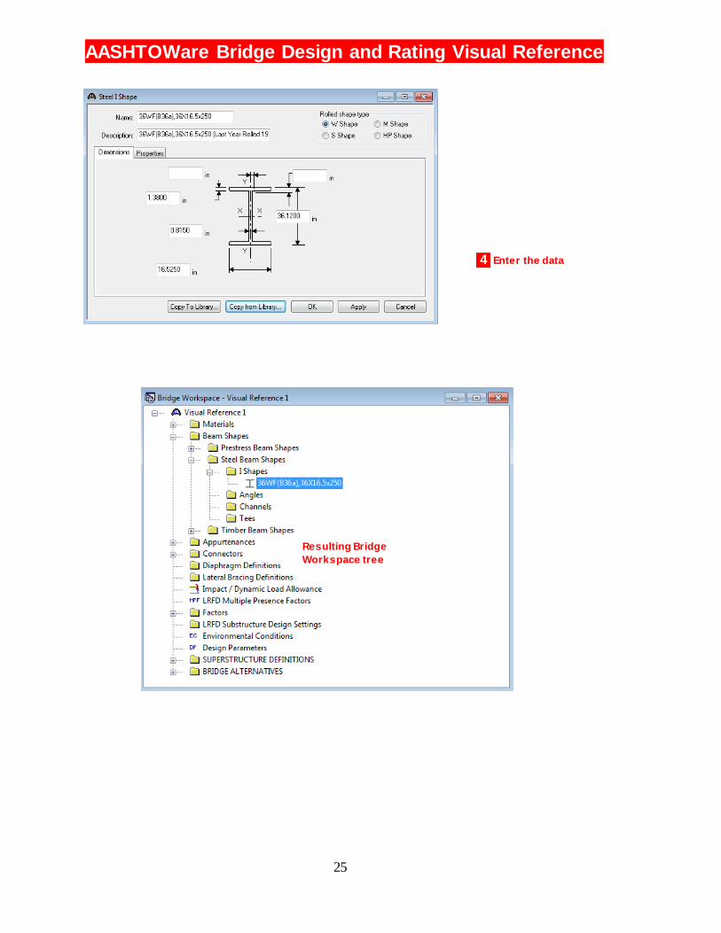
4 Enter the data
Resulting Bridge
Workspace tree
AASHTOWare Bridge Design and Rating Visual Reference
26
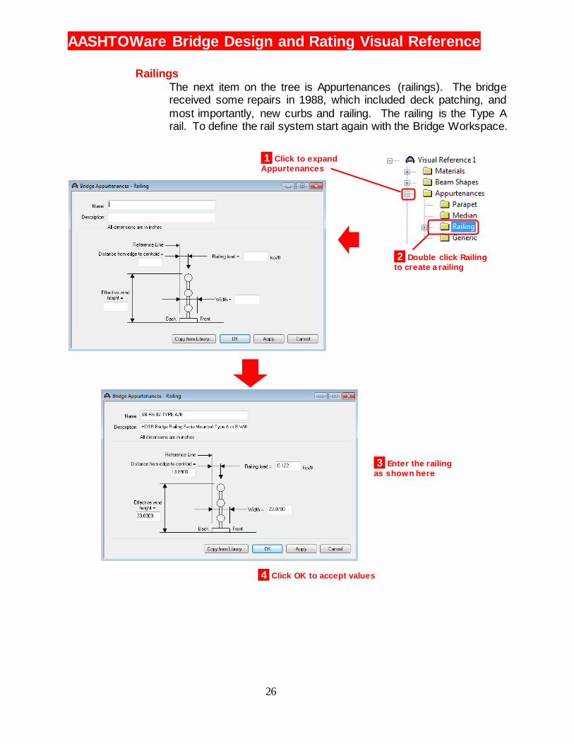
Railings
The next item on the tree is Appurtenances (railings). The bridge received some repairs in 1988, which included deck patching, and
most importantly, new curbs and railing. The railing is the Type A rail. To define the rail system start again with the Bridge Workspace.
1 Click to expand
Appurtenances
2 Double click Railing
to create a railing
3 Enter the railing
as shown here
4 Click OK to accept values
AASHTOWare Bridge Design and Rating Visual Reference
27
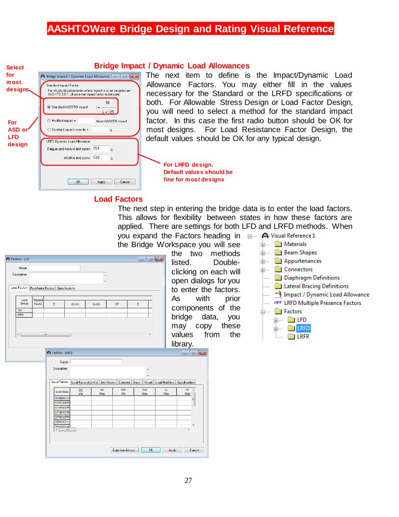
Bridge Impact / Dynamic Load Allowances
The next item to define is the Impact/Dynamic Load
Allowance Factors. You may either fill in the values necessary for the Standard or the LRFD specifications or both. For Allowable Stress Design or Load Factor Design, you will need to select a method for the standard impact
factor. In this case the first radio button should be OK for most designs. For Load Resistance Factor Design, the default values should be OK for any typical design.
Load Factors
The next step in entering the bridge data is to enter the load factors. This allows for flexibility between states in how these factors are applied. There are settings for both LFD and LRFD methods. When
you expand the Factors heading in the Bridge Workspace you will see
the two methods listed. Double-
clicking on each will open dialogs for you to enter the factors. As with prior
components of the bridge data, you may copy these values from the
library.
For LRFD design.
Default values should be
fine for most designs
For
ASD or
LFD
design
Select
for
most
designs
For
ASD or
LFD
design

AASHTOWare Bridge Design and Rating Visual Reference
28
At this point we have completed all the supporting data for the bridge. Your Bridge Workspace should look like the figure to the right. The next step will be to
enter the bridge definition.
Creating a Bridge Definition
To start a new Bridge Definition Double-click on the heading
SUPERSTRUCTURE DEFINITIONS. This will bring up a dialog that you will enter the bridge dimensions and materials.
This will create a new branch of the tree where you will enter more components for this definition.
1 To Begin a Structure Definition,
Double Click Here
2 Select Girder System Superstructure since this
w ill be a typical bridge that
can be modeled in BrDR
3 Click OK to Continue
Super Structure Types
Girder System
Girder Line
Floor System
Floor Line
Allows you to enter each beam independently and define their position on the bridge. This is used for most bridges.
Allows you to enter the bridge using one representative girder. This allows for more simplified assumptions to be made about distribution factors and other aspects of the bridge. This should only be used for more complicated structures that cannot be modeled easily in Virtis Opis.
Essentially the same as a Girder System, but used in a deck using stringers and floor beams.
Essentially the same as a Girder Line, but used in a deck using stringers and floor beams.
AASHTOWare Bridge Design and Rating Visual Reference
29
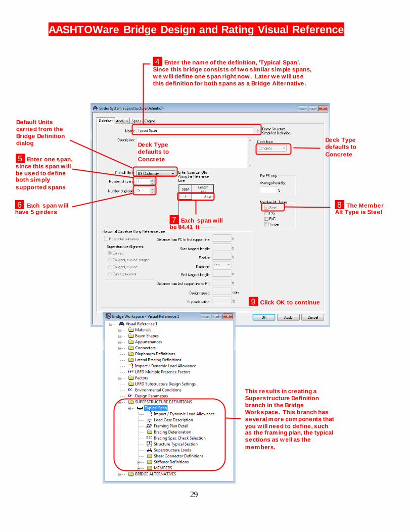
4 Enter the name of the definition, ‘Typical Span’.
Since this bridge consists of two similar simple spans,
we will define one span right now. Later we will use
this definition for both spans as a Bridge Alternative.
5 Enter one span, since this span will
be used to define
both simply
supported spans.
6 Each span will have five girders
7 Each span will be 84.41 ft
8 The Member Alt Type is Steel
9 Click OK to continue
Deck Type
defaults to
Concrete
This results in creating a
Superstructure Definition
branch in the Bridge
Workspace. This branch has
several more components that
you will need to define, such as the framing plan, the typical
sections as well as the
members.
Default units are
carried from the
Bridge Definition
dialog Deck Type
defaults to
Concrete
Default Units
carried from the
Bridge Definition
dialog
5 Enter one span,
since this span will
be used to define both simply
supported spans
6 Each span will have 5 girders
AASHTOWare Bridge Design and Rating Visual Reference
30
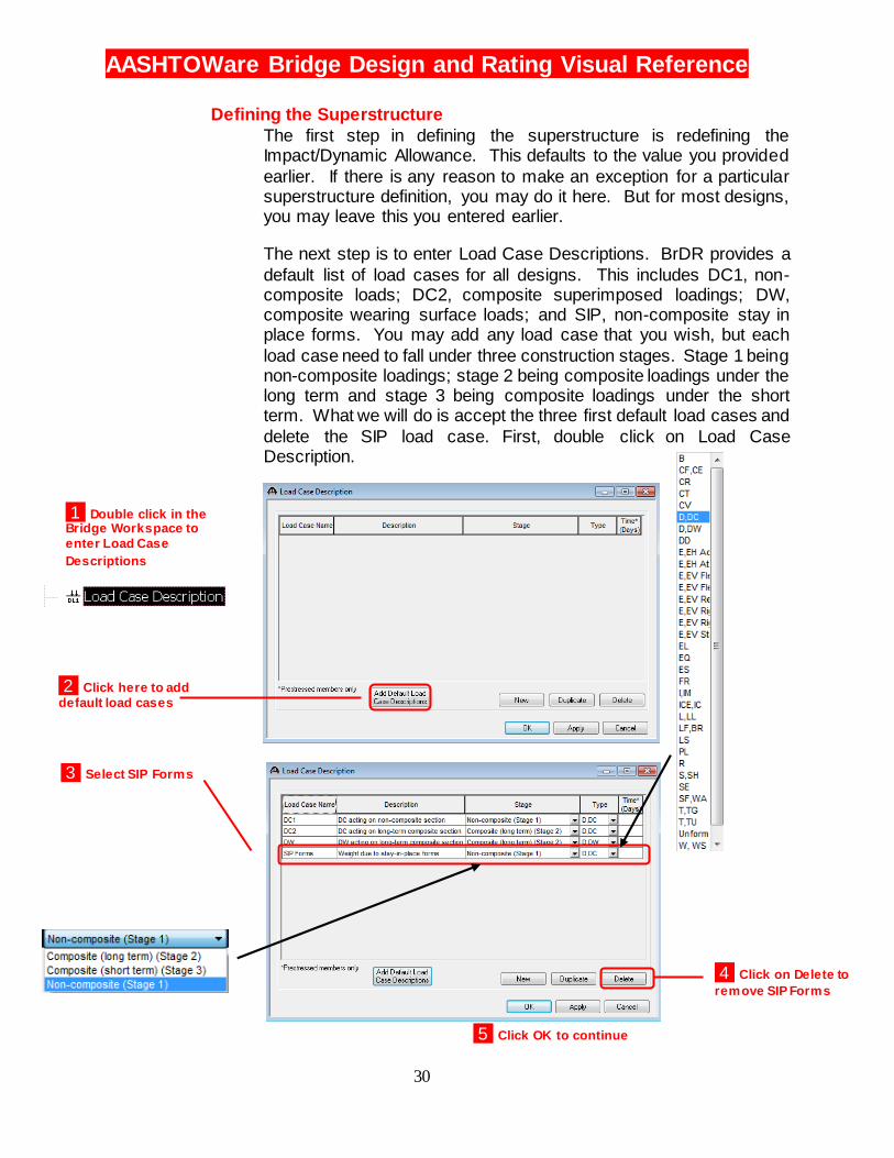
Defining the Superstructure
The first step in defining the superstructure is redefining the Impact/Dynamic Allowance. This defaults to the value you provided
earlier. If there is any reason to make an exception for a particular superstructure definition, you may do it here. But for most designs, you may leave this you entered earlier.
The next step is to enter Load Case Descriptions. BrDR provides a
default list of load cases for all designs. This includes DC1, non-composite loads; DC2, composite superimposed loadings; DW, composite wearing surface loads; and SIP, non-composite stay in place forms. You may add any load case that you wish, but each
load case need to fall under three construction stages. Stage 1 being non-composite loadings; stage 2 being composite loadings under the long term and stage 3 being composite loadings under the short term. What we will do is accept the three first default load cases and
delete the SIP load case. First, double click on Load Case Description.
1 Double click in the Bridge Workspace to
enter Load Case
Descriptions
2 Click here to add
default load cases
4 Click on Delete to
remove SIP Forms
5 Click OK to continue
3 Select SIP Forms
AASHTOWare Bridge Design and Rating Visual Reference
31
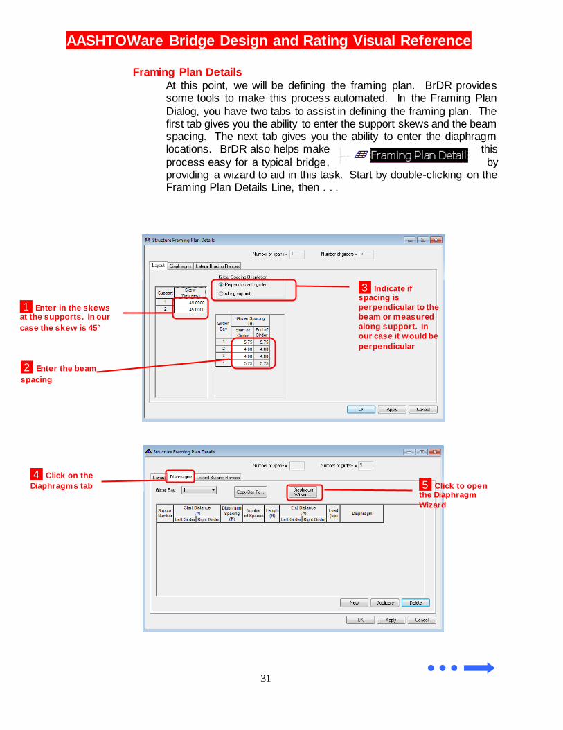
Framing Plan Details
At this point, we will be defining the framing plan. BrDR provides some tools to make this process automated. In the Framing Plan
Dialog, you have two tabs to assist in defining the framing plan. The first tab gives you the ability to enter the support skews and the beam spacing. The next tab gives you the ability to enter the diaphragm locations. BrDR also helps make this
process easy for a typical bridge, by providing a wizard to aid in this task. Start by double-clicking on the Framing Plan Details Line, then . . .
1 Enter in the skews at the supports. In our
case the skew is 45°
2 Enter the beam
spacing
3 Indicate if spacing is
perpendicular to the
beam or measured
along support. In
our case it would be
perpendicular
4 Click on the
Diaphragms tab 5 Click to open the Diaphragm
Wizard
4 Click on the
Diaphragms tab

AASHTOWare Bridge Design and Rating Visual Reference
32
6 This dialog may pop. If so, it is telling you apply all
changes before entering the
wizard. In our case, click Yes
7 Select the correct
diaphragm layour scheme
8 Click Next to continue
9 Select the reference girder. This would
typically be the left
girder 10 Enter the distance from the end diaphragm
to the first interior
diaphragm. Then enter
the diaphragm spacing
thereafter
11 Click Finish to populate the diaphragm layout dialog
Resulting diaphragm
layout automatically
entered from the wizard
12 Click OK to continue
9 Enter the distance from the end diaphragm to the
first interior diaphragm.
Then enter the diaphragm
spacing thereafter.
AASHTOWare Bridge Design and Rating Visual Reference
33
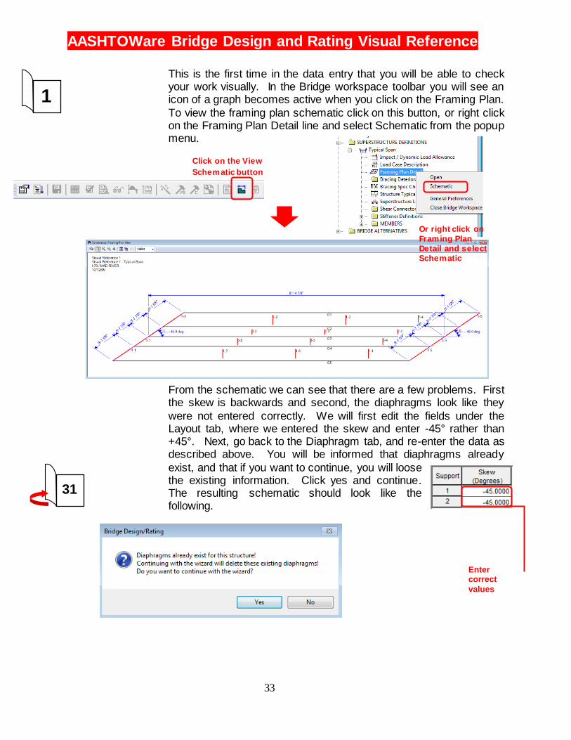
This is the first time in the data entry that you will be able to check your work visually. In the Bridge workspace toolbar you will see an icon of a graph becomes active when you click on the Framing Plan.
To view the framing plan schematic click on this button, or right click on the Framing Plan Detail line and select Schematic from the popup menu.
From the schematic we can see that there are a few problems. First the skew is backwards and second, the diaphragms look like they
were not entered correctly. We will first edit the fields under the Layout tab, where we entered the skew and enter -45° rather than +45°. Next, go back to the Diaphragm tab, and re-enter the data as described above. You will be informed that diaphragms already
exist, and that if you want to continue, you will loose the existing information. Click yes and continue. The resulting schematic should look like the following.
Enter correct
values
1
31
Click on the View
Schematic button
Or right click on
Framing Plan
Detail and select
Schematic
AASHTOWare Bridge Design and Rating Visual Reference
34
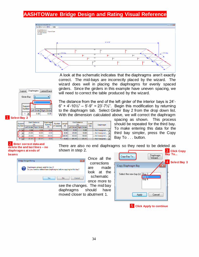
A look at the schematic indicates that the diaphragms aren’t exactly
correct. The mid-bays are incorrectly placed by the wizard. The wizard does well in placing the diaphragms for evenly spaced girders. Since the girders in this example have uneven spacing, we will need to correct the table produced by the wizard.
The distance from the end of the left girder of the interior bays is 24’-6” + 4’-10½” – 5’-9” = 23’-7½”. Begin this modification by returning to the diaphragm tab. Select Girder Bay 2 from the drop down list. With the dimension calculated above, we will correct the diaphragm
spacing as shown. This process should be repeated for the third bay. To make entering this data for the third bay simpler, press the Copy
Bay To . . . button.
There are also no end diaphragms so they need to be deleted as shown in step 2.
Once all the
corrections are made look at the
schematic
once more to see the changes. The mid bay diaphragms should have moved closer to abutment 1.
1 Select Bay 2
2 Enter correct data and delete the and last lines – no
diaphragms at ends of
beams
3 Click Copy Bay To...
4 Select Bay 3
5 Click Apply to continue
AASHTOWare Bridge Design and Rating Visual Reference
35
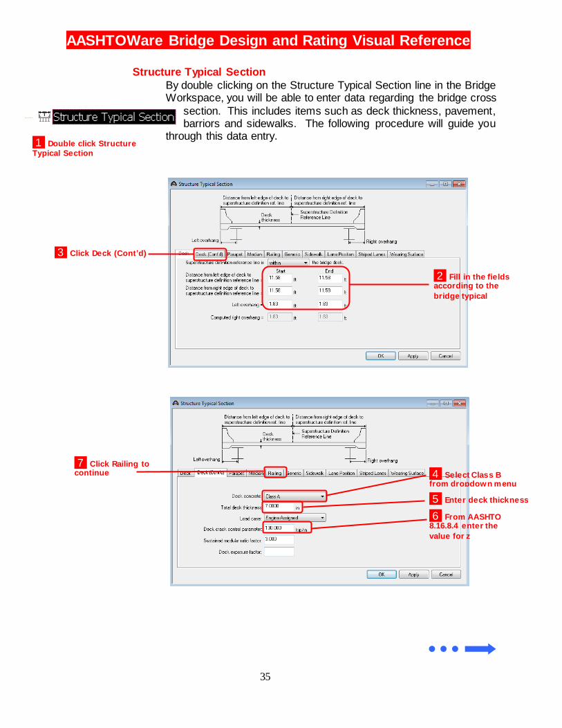
Structure Typical Section
By double clicking on the Structure Typical Section line in the Bridge Workspace, you will be able to enter data regarding the bridge cross
section. This includes items such as deck thickness, pavement, barriors and sidewalks. The following procedure will guide you
through this data entry.
1 Double click Structure
Typical Section
2 Fill in the fields according to the
bridge typical
3 Click Deck (Cont’d)
4 Select Class B from dropdown menu
5 Enter deck thickness
6 From AASHTO 8.16.8.4 enter the
value for z
7 Click Railing to continue
AASHTOWare Bridge Design and Rating Visual Reference
36
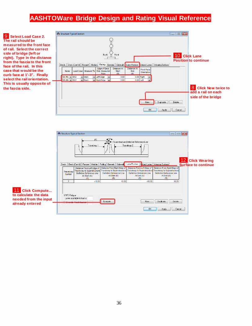
9 Select Load Case 2. The rail should be
measured to the front face
of rail. Select the correct
side of bridge (left or
right). Type in the distance
from the fascia to the front
face of the rail. In this
case that would be the
curb face at 1’-3”. Finally
select the rail orientation.
This is usually opposite of
the fascia side.
10 Click Lane
Position to continue
12 Click Wearing
Surface to continue 11 Click Compute…
to calculate the data
needed from input
already entered
11 Click Compute...
to calculate the data
needed from the input
already entered
8 Click New twice to add a rail on each
side of the bridge

AASHTOWare Bridge Design and Rating Visual Reference
37
13 Click Copy from Library . . . and select
Bituminous Concrete
Pavement
15 Select DW from
drop down list.
16 Click on OK to Continue
17 Display Schematic in the
same way we did
for the framing
plan detail
14 Enter Pavement
Thickness
33
AASHTOWare Bridge Design and Rating Visual Reference
38
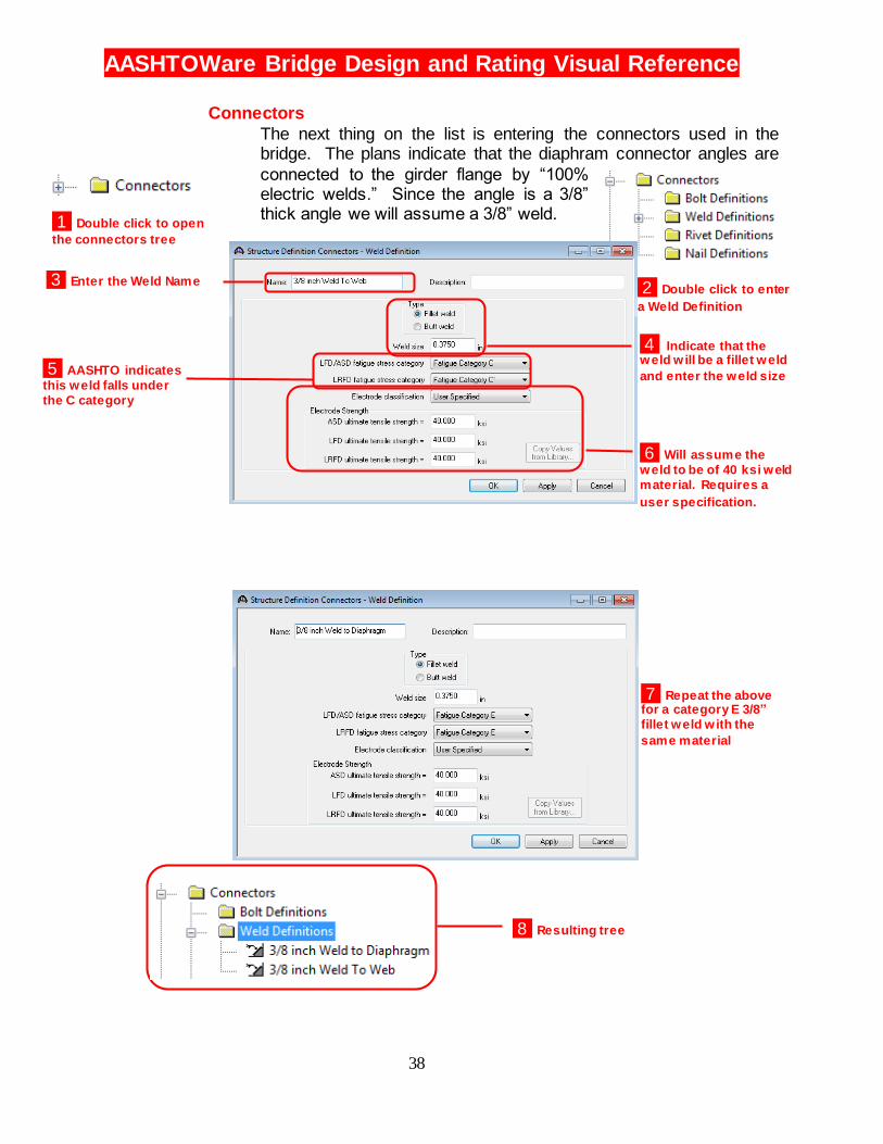
Connectors
The next thing on the list is entering the connectors used in the bridge. The plans indicate that the diaphram connector angles are
connected to the girder flange by “100% electric welds.” Since the angle is a 3/8” thick angle we will assume a 3/8” weld.
1 Double click to open
the connectors tree
2 Double click to enter
a Weld Definition
8 Resulting tree
4 Indicate that the weld w ill be a fillet weld
and enter the weld size
6 Will assume the
weld to be of 40 ksi weld
material. Requires a
user specification.
3 Enter the Weld Name
5 AASHTO indicates
this weld falls under
the C category
7 Repeat the above for a category E 3/8”
fillet weld w ith the
same material
AASHTOWare Bridge Design and Rating Visual Reference
39
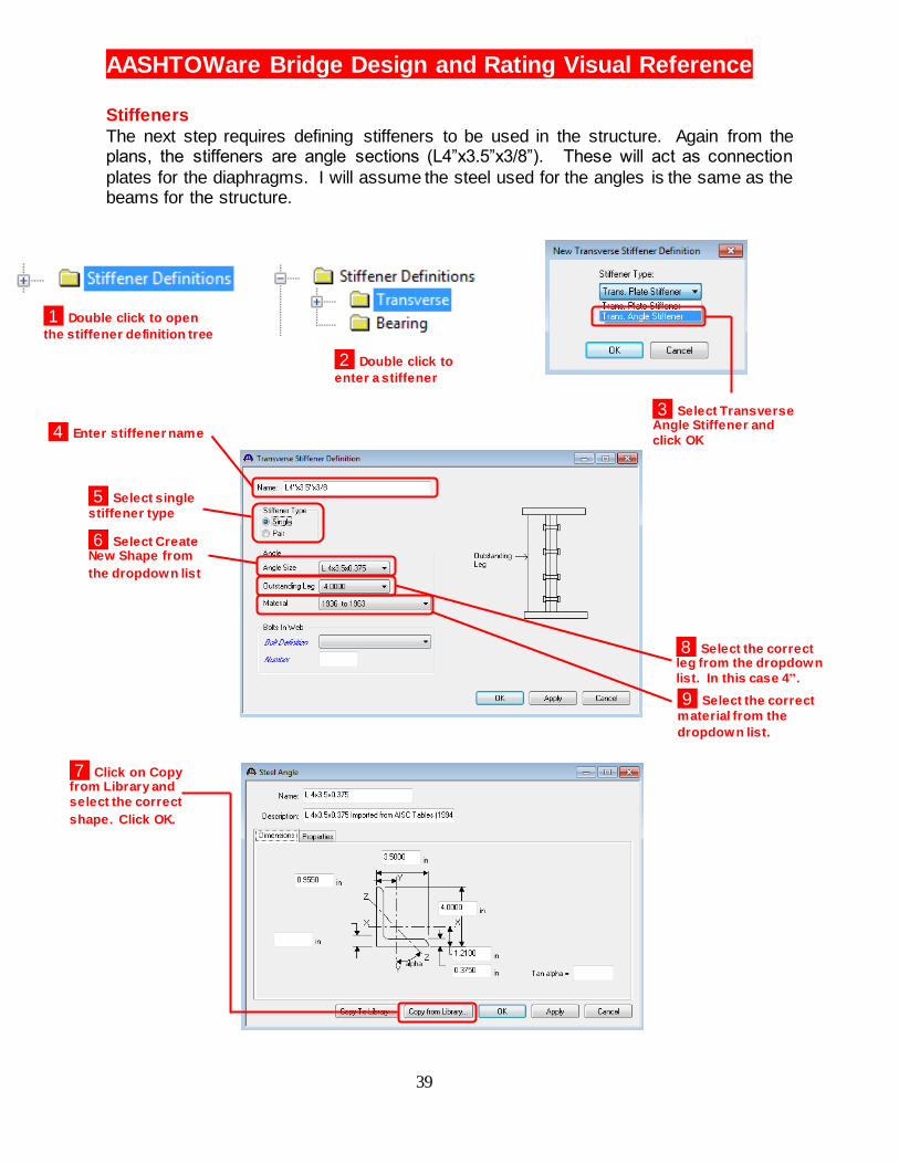
Stiffeners
The next step requires defining stiffeners to be used in the structure. Again from the plans, the stiffeners are angle sections (L4”x3.5”x3/8”). These will act as connection
plates for the diaphragms. I will assume the steel used for the angles is the same as the beams for the structure.
1 Double click to open
the stiffener definition tree
2 Double click to
enter a stiffener
3 Select Transverse Angle Stiffener and
click OK
4 Enter stiffener name
5 Select single
stiffener type
6 Select Create New Shape from
the dropdown list
7 Click on Copy from Library and
select the correct
shape. Click OK.
8 Select the correct leg from the dropdown
list. In this case 4”.
9 Select the correct
material from the
dropdown list.
AASHTOWare Bridge Design and Rating Visual Reference
40
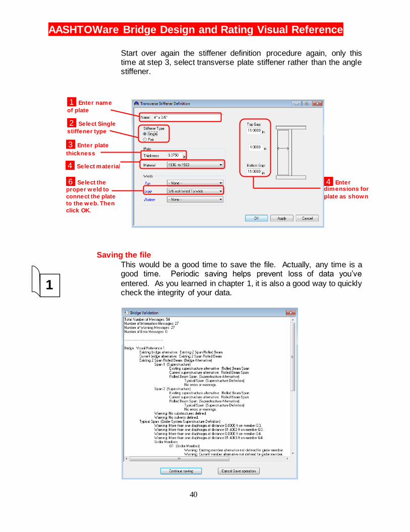
Start over again the stiffener definition procedure again, only this time at step 3, select transverse plate stiffener rather than the angle stiffener.
Saving the file
This would be a good time to save the file. Actually, any time is a good time. Periodic saving helps prevent loss of data you’ve
entered. As you learned in chapter 1, it is also a good way to quickly check the integrity of your data.
1
1 Enter name
of plate
2 Select Single
stiffener type
3 Enter plate
thickness
4 Select material
6 Select the
proper weld to
connect the plate
to the web. Then
click OK.
4 Enter dimensions for
plate as shown
AASHTOWare Bridge Design and Rating Visual Reference
41
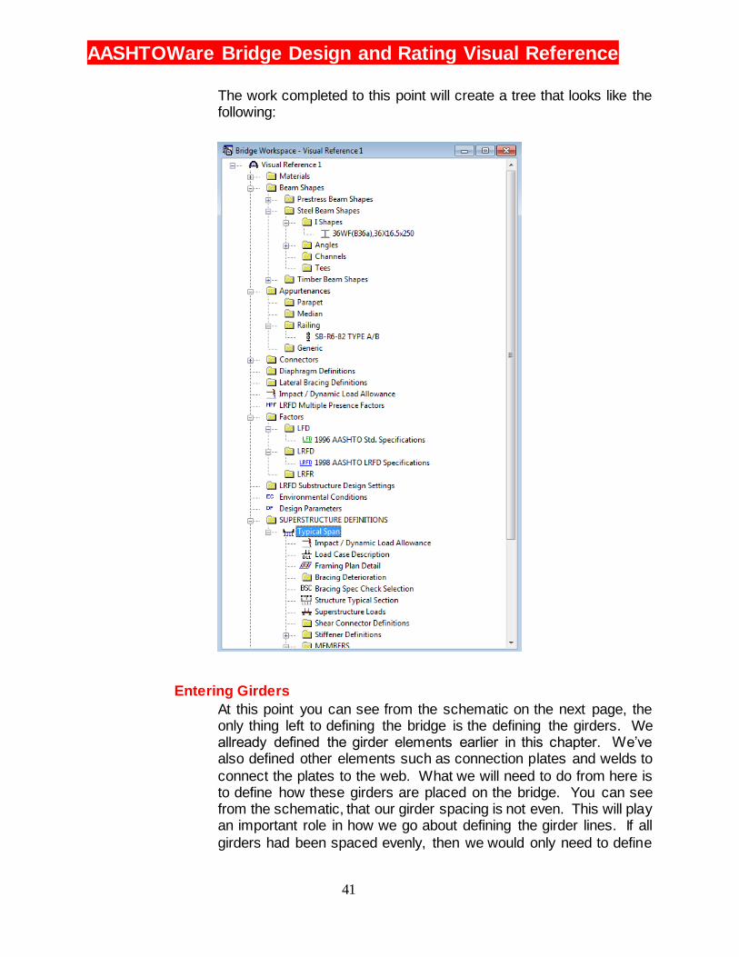
The work completed to this point will create a tree that looks like the following:
Entering Girders
At this point you can see from the schematic on the next page, the only thing left to defining the bridge is the defining the girders. We allready defined the girder elements earlier in this chapter. We’ve also defined other elements such as connection plates and welds to
connect the plates to the web. What we will need to do from here is to define how these girders are placed on the bridge. You can see from the schematic, that our girder spacing is not even. This will play an important role in how we go about defining the girder lines. If all
girders had been spaced evenly, then we would only need to define

AASHTOWare Bridge Design and Rating Visual Reference
42
one girder then the rest would simply be a reference to the first. But
since the spacing varies slightly, we will need to define girder lines with different spaces.
2-22
3 Double click on MEMBER ALTERNATIVES to begin the
process of entering a beam
alternative
1 Click on the ‘+’ to open the Members
tree
2 Click on the ‘+’ next to G1 to open
the Girder tree
4 Select Steel from the Material Type and
select Rolled from
the Girder Type.
Click OK.
AASHTOWare Bridge Design and Rating Visual Reference
43
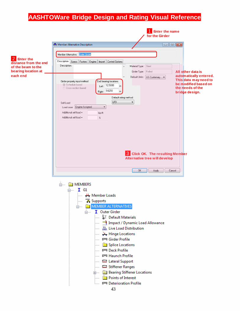
2 Enter the distance from the end
of the beam to the
bearing location at
each end
3 Click OK. The resulting Member
Alternative tree w ill develop
All other data is
automatically entered.
This data may need to
be modified based on the needs of the
bridge design.
1 Enter the name
for the Girder
AASHTOWare Bridge Design and Rating Visual Reference
44
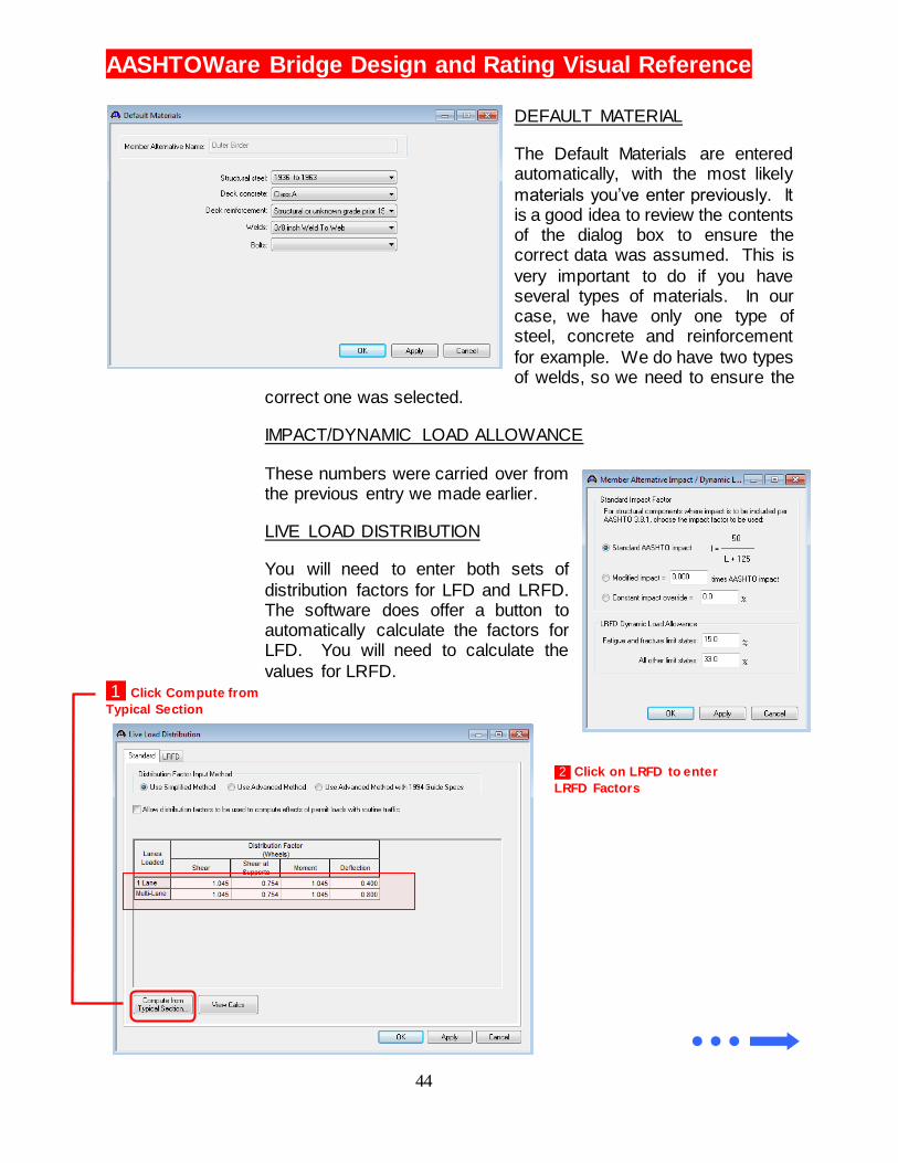
DEFAULT MATERIAL
The Default Materials are entered automatically, with the most likely
materials you’ve enter previously. It is a good idea to review the contents of the dialog box to ensure the correct data was assumed. This is
very important to do if you have several types of materials. In our case, we have only one type of steel, concrete and reinforcement
for example. We do have two types of welds, so we need to ensure the
correct one was selected.
IMPACT/DYNAMIC LOAD ALLOWANCE
These numbers were carried over from the previous entry we made earlier.
LIVE LOAD DISTRIBUTION
You will need to enter both sets of
distribution factors for LFD and LRFD. The software does offer a button to automatically calculate the factors for LFD. You will need to calculate the
values for LRFD.
1 Click Compute from
Typical Section
2 Click on LRFD to enter
LRFD Factors
AASHTOWare Bridge Design and Rating Visual Reference
45
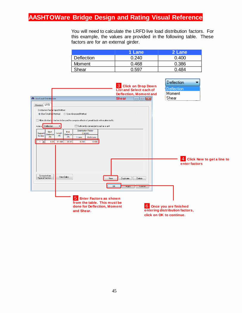
You will need to calculate the LRFD live load distribution factors. For this example, the values are provided in the following table. These factors are for an external girder.
1 Lane 2 Lane
Deflection 0.240 0.400
Moment 0.468 0.386
Shear 0.597 0.484
3 Click on Drop Down List and Select each of
Deflection, Moment and
Shear
4 Click New to get a line to
enter factors
5 Enter Factors as shown
from the table. This must be done for Deflection, Moment
and Shear. 6 Once you are finished entering distribution factors,
click on OK to continue.
AASHTOWare Bridge Design and Rating Visual Reference
46
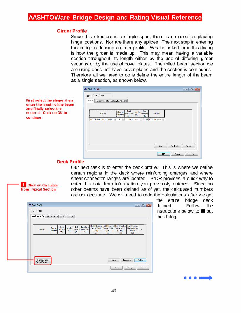
Girder Profile
Since this structure is a simple span, there is no need for placing hinge locations. Nor are there any splices. The next step in entering
this bridge is defining a girder profile. What is asked for in this dialog is how the girder is made up. This may mean having a variable section throughout its length either by the use of differing girder sections or by the use of cover plates. The rolled beam section we
are using does not have cover plates and the section is continuous. Therefore all we need to do is define the entire length of the beam as a single section, as shown below.
Deck Profile
Our next task is to enter the deck profile. This is where we define
certain regions in the deck where reinforcing changes and where shear connector ranges are located. BrDR provides a quick way to enter this data from information you previously entered. Since no other beams have been defined as of yet, the calculated numbers
are not accurate. We will need to redo the calculations after we get the entire bridge deck defined. Follow the instructions below to fill out
the dialog.
First select the shape, then
enter the length of the beam
and finally select the
material. Click on OK to
continue.
1 Click on Calculate
from Typical Section
AASHTOWare Bridge Design and Rating Visual Reference
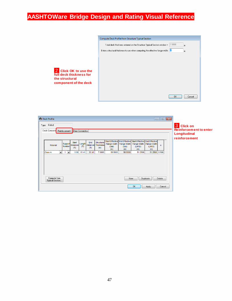
47
2 Click OK to use the full deck thickness for
the structural
component of the deck
3 Click on Reinforcement to enter
Longitudinal
reinforcement
AASHTOWare Bridge Design and Rating Visual Reference
48
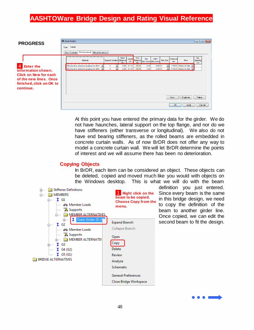
At this point you have entered the primary data for the girder. We do not have haunches, lateral support on the top flange, and nor do we have stiffeners (either transverse or longitudinal). We also do not
have end bearing stiffeners, as the rolled beams are embedded in concrete curtain walls. As of now BrDR does not offer any way to model a concrete curtain wall. We will let BrDR determine the points of interest and we will assume there has been no deterioration.
Copying Objects
In BrDR, each item can be considered an object. These objects can be deleted, copied and moved much like you would with objects on the Windows desktop. This is what we will do with the beam
definition you just entered. Since every beam is the same in this bridge design, we need to copy the definition of the
beam to another girder line. Once copied, we can edit the second beam to fit the design.
4 Enter the information shown.
Click on New for each
of the new lines. Once
finished, click on OK to
continue.
PROGRESS
1 Right click on the beam to be copied.
Choose Copy from the
menu.
AASHTOWare Bridge Design and Rating Visual Reference
49
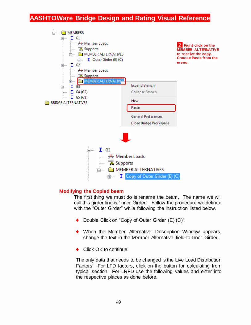
Modifying the Copied beam
The first thing we must do is rename the beam. The name we will call this girder line is “Inner Girder”. Follow the procedure we defined with the “Outer Girder” while following the instruction listed below.
Double Click on “Copy of Outer Girder (E) (C)”.
When the Member Alternative Description Window appears,
change the text in the Member Alternative field to Inner Girder.
Click OK to continue.
The only data that needs to be changed is the Live Load Distribution
Factors. For LFD factors, click on the button for calculating from typical section. For LRFD use the following values and enter into the respective places as done before.
2 Right click on the
MEMBER ALTERNATIVE
to receive the copy. Choose Paste from the
menu.
AASHTOWare Bridge Design and Rating Visual Reference
50
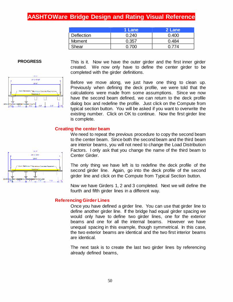
1 Lane 2 Lane
Deflection 0.240 0.400
Moment 0.357 0.484
Shear 0.700 0.774
This is it. Now we have the outer girder and the first inner girder created. We now only have to define the center girder to be completed with the girder definitions.
Before we move along, we just have one thing to clean up. Previously when defining the deck profile, we were told that the calculations were made from some assumptions. Since we now have the second beam defined, we can return to the deck profile
dialog box and redefine the profile. Just click on the Compute from typical section button. You will be asked if you want to overwrite the existing number. Click on OK to continue. Now the first girder line is complete.
Creating the center beam
We need to repeat the previous procedure to copy the second beam to the center beam. Since both the second beam and the third beam are interior beams, you will not need to change the Load Distribution
Factors. I only ask that you change the name of the third beam to Center Girder.
The only thing we have left is to redefine the deck profile of the second girder line. Again, go into the deck profile of the second
girder line and click on the Compute from Typical Section button.
Now we have Girders 1, 2 and 3 completed. Next we will define the fourth and fifth girder lines in a different way.
Referencing Girder Lines
Once you have defined a girder line. You can use that girder line to define another girder line. If the bridge had equal girder spacing we would only have to define two girder lines, one for the exterior beams and one for all the internal beams. However we have
unequal spacing in this example, though symmetrical. In this case, the two exterior beams are identical and the two first interior beams are identical.
The next task is to create the last two girder lines by referencing
already defined beams,
PROGRESS

AASHTOWare Bridge Design and Rating Visual Reference
51
2 Click on the drop down list and select the similar girder line you will
be referencing. In this case, G2 is
similar to G4. Click OK to continue.
3 BrDR will give you a warning that all properties should be the
same in both the girder line you are
working on and the girder line you
are referencing. Just click
Continue.
1 Double click on the Girder Line to
edit, in this case G4
4 Repeat this procedure for
Girder line 5 (G5) by referencing
Girder Line 1 (G1).
AASHTOWare Bridge Design and Rating Visual Reference
52
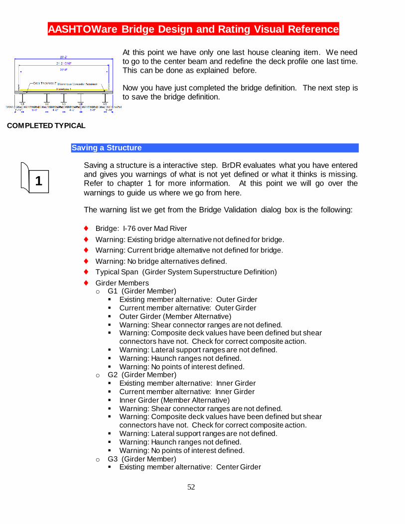
At this point we have only one last house cleaning item. We need to go to the center beam and redefine the deck profile one last time. This can be done as explained before.
Now you have just completed the bridge definition. The next step is to save the bridge definition.
Saving a Structure
Saving a structure is a interactive step. BrDR evaluates what you have entered and gives you warnings of what is not yet defined or what it thinks is missing. Refer to chapter 1 for more information. At this point we will go over the
warnings to guide us where we go from here.
The warning list we get from the Bridge Validation dialog box is the following:
Bridge: I-76 over Mad River
Warning: Existing bridge alternative not defined for bridge.
Warning: Current bridge alternative not defined for bridge.
Warning: No bridge alternatives defined.
Typical Span (Girder System Superstructure Definition)
Girder Members o G1 (Girder Member)
Existing member alternative: Outer Girder Current member alternative: Outer Girder Outer Girder (Member Alternative) Warning: Shear connector ranges are not defined. Warning: Composite deck values have been defined but shear
connectors have not. Check for correct composite action. Warning: Lateral support ranges are not defined. Warning: Haunch ranges not defined. Warning: No points of interest defined.
o G2 (Girder Member) Existing member alternative: Inner Girder Current member alternative: Inner Girder Inner Girder (Member Alternative) Warning: Shear connector ranges are not defined. Warning: Composite deck values have been defined but shear
connectors have not. Check for correct composite action. Warning: Lateral support ranges are not defined. Warning: Haunch ranges not defined. Warning: No points of interest defined.
o G3 (Girder Member) Existing member alternative: Center Girder
1
COMPLETED TYPICAL

AASHTOWare Bridge Design and Rating Visual Reference
53
Current member alternative: Center Girder Center Girder (Member Alternative) Warning: Shear connector ranges are not defined. Warning: Composite deck values have been defined but shear
connectors have not. Check for correct composite action. Warning: Lateral support ranges are not defined. Warning: Haunch ranges not defined. Warning: No points of interest defined.
o G4 (Girder Member) Linked to G2.
o G5 (Girder Member) Linked to G1.
Explanation of Warnings
The first three warnings listed above refer to the same thing. We have yet to define a bridge alternative. We will do this soon. At this
point we want to see if the bridge definition we have entered is valid. So for now we will skip the first three warnings.
As to the rest, each of the three girder lines, G1, G2 and G3, have identical warnings. According to the bridge file the bridge deck is not
composite. Therefore the first two warnings can be ignored. The BRASS engine will assume the deck design is not composite.
The plans in the file also did not include any haunches. The deck essentially is placed on top of the top flange. This being the case the
top flange is not being laterally restrained. Therefore we can ignore the third and fourth warning.
Regarding the last warning, we have not entered any points of interest. The BRASS engine will automatically use 11 evenly spaced
points along the girder line if no information is supplied by the user. In this case, we will let BRASS create the points.
Since we are comfortable with the bridge definition, we can continue on to creating a Bridge Alternative.
AASHTOWare Bridge Design and Rating Visual Reference
54
Bridge Alternative
What is a Bridge Alternative?
A Bridge Alternative is essentially a bridge location or a particular
bridge length. For an already existing Bridge, this would be the current location, and therefore, you would only have one alternative. A design may have a few different alignments. If this is the case, there may be an individual bridge location for each alignment. There
may also be several different lengths or configurations of the bridge you wish to study. In any case, each bridge you study shall have their own alternative definition.
Now it’s asking for Structures!
After you’ve defined a Bridge Alternative, it will now ask for the structures in the bridge. What this means is that you now need to define what makes up the bridge. If you have a single simple span bridge, you would just define a single structure. If however, you have
a bridge that contains a prestressed BrDRided slab span going over a rail road followed by a steel girder span going over a river, this single Bridge Alternative comprises of two Structures. In this case we will need to enter each structure.
What is a Structure Alternative? Didn’t I already enter that?
A Structure alternative is where you enter the different bridge types you wish to study. For a particular span, you may want to compare a steel girder and a concrete girder deck system. In this case you
will have entered these Bridge Definitions as we have done above for each bridge type. Then in the Structure Alternatives, you will enter the chosen alternatives you wish to study. This essentially is where you connect the Bridge Definition to the Bridge Alternative.
There is no rule that says that you cannot have more Bridge Definitions defined, than you have entered in your alternatives. Consider the Bridge Definitions section as a library, and the Structure Alternative entries being where you actually take out the book!
In our case . . .
We have a single Bridge Alternative with two identical spans. What we need to do is define a single Bridge Alternative. Following that, we need to define a single Structure for that alternative. Finally we
need to describe that structure as being two spans, using the Bridge Definition we entered earlier for both spans.
AASHTOWare Bridge Design and Rating Visual Reference
55
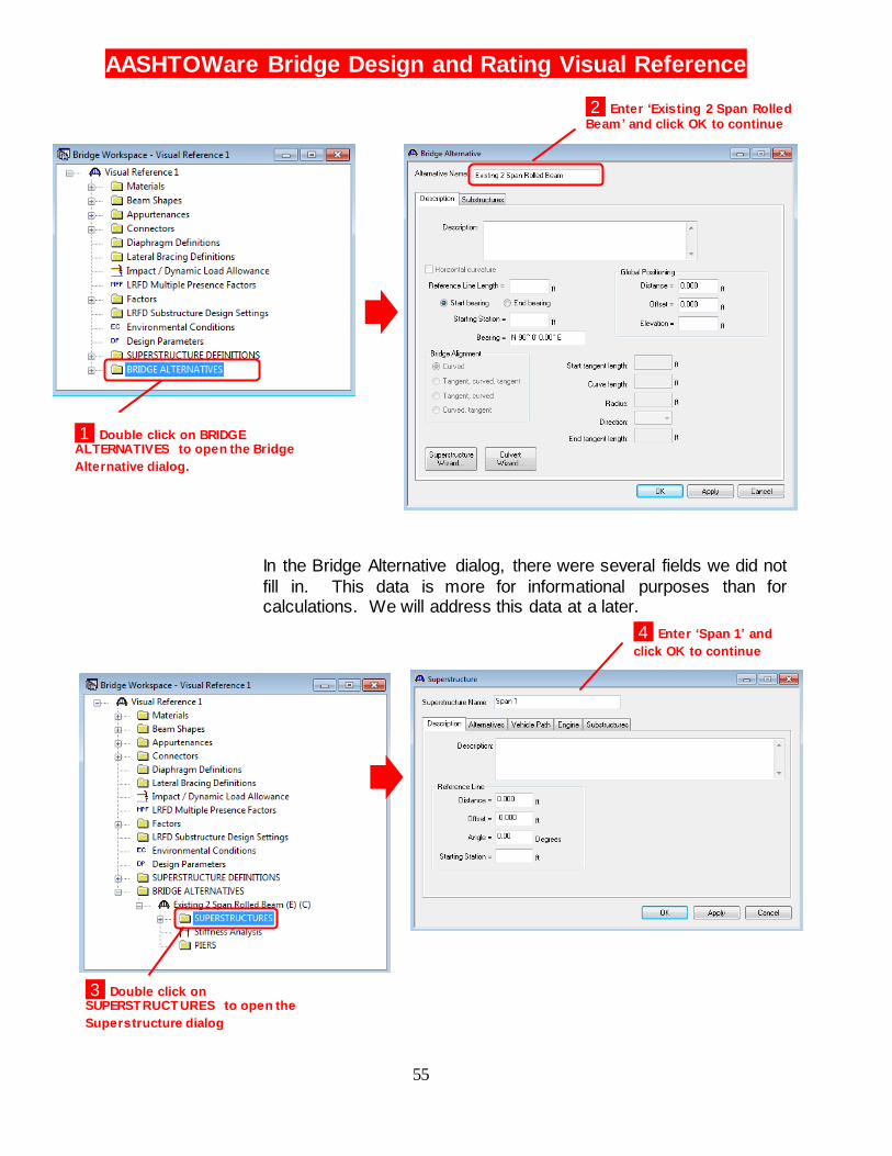
In the Bridge Alternative dialog, there were several fields we did not
fill in. This data is more for informational purposes than for calculations. We will address this data at a later.
1 Double click on BRIDGE ALTERNATIVES to open the Bridge
Alternative dialog
2 Enter ‘Existing 2 Span Rolled
Beam ’ and click OK to continue
3 Double click on SUPERSTRUCTURES to open the
Superstructure dialog
4 Enter ‘Span 1’ and
click OK to continue
1 Double click on BRIDGE ALTERNATIVES to open the Bridge
Alternative dialog.
AASHTOWare Bridge Design and Rating Visual Reference
56
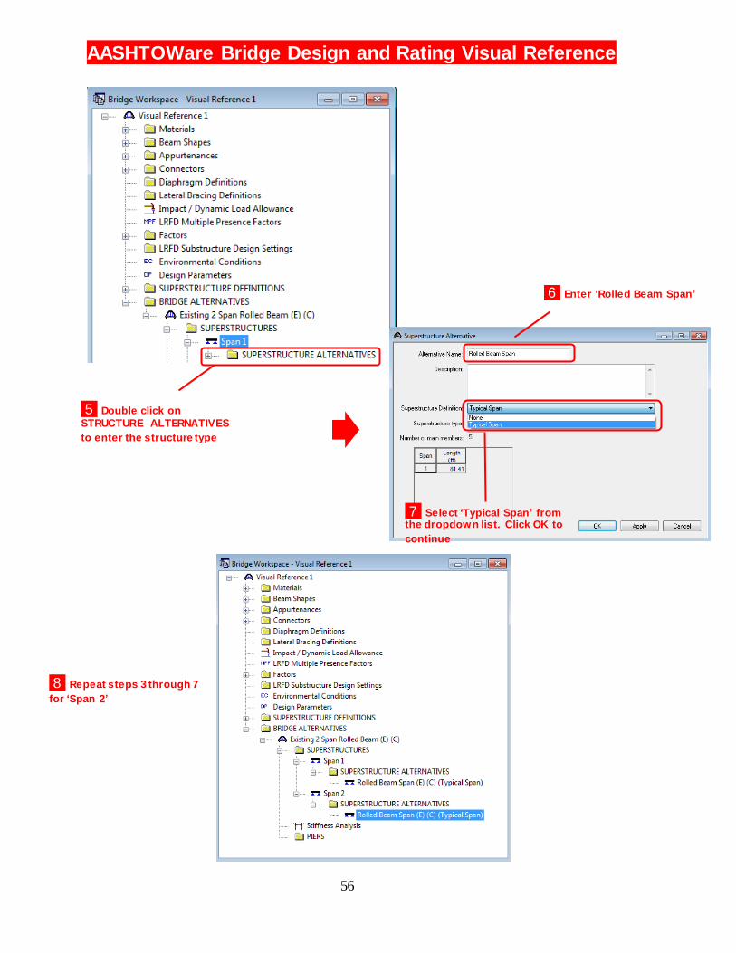
6 Enter ‘Rolled Beam Span’
5 Double click on
STRUCTURE ALTERNATIVES
to enter the structure type
7 Select ‘Typical Span’ from the dropdown list. Click OK to
continue
8 Repeat steps 3 through 7
for ‘Span 2’

AASHTOWare Bridge Design and Rating Visual Reference
57
At this point the bridge alternative is fully defined. We are ready to start the Bridge Design.
Checking the Bridge Data
Before continuing, you should save your work as well as check the input. In our earlier check of the input, we discovered we had some warnings regarding not having a Bridge Alternative defined. As we save the bridge data we will find that those warnings are now gone.
You can see the structure of our Bridge Alternative Data in the screen shot above.
At this point we are ready to run a design.
Running a Design
Define Design Trucks
The first step is to define the Live load. This is done by bringing up
the Analysis Settings dialog box. Click the button as shown to the right, or use the menus. (Bridge > Analysis Settings…).
1 Click View Analysis
Settings to select the live load
for the design check.

AASHTOWare Bridge Design and Rating Visual Reference
58
1 Click Open Template to set up the typical LRFD Live
Loading for Design.
2 Select HL 93 Design
Review and click on Open.
3 Click on OK to continue

AASHTOWare Bridge Design and Rating Visual Reference
59
Running the Analysis
At this point you are ready to run the Analysis. To do this, click on the analysis button in the tool bar. Or if you want to go through the
menus, (Bridge > Analyze). The analysis window will appear and then the calculations will begin.
AASHTOWare Bridge Design and Rating Visual Reference
60
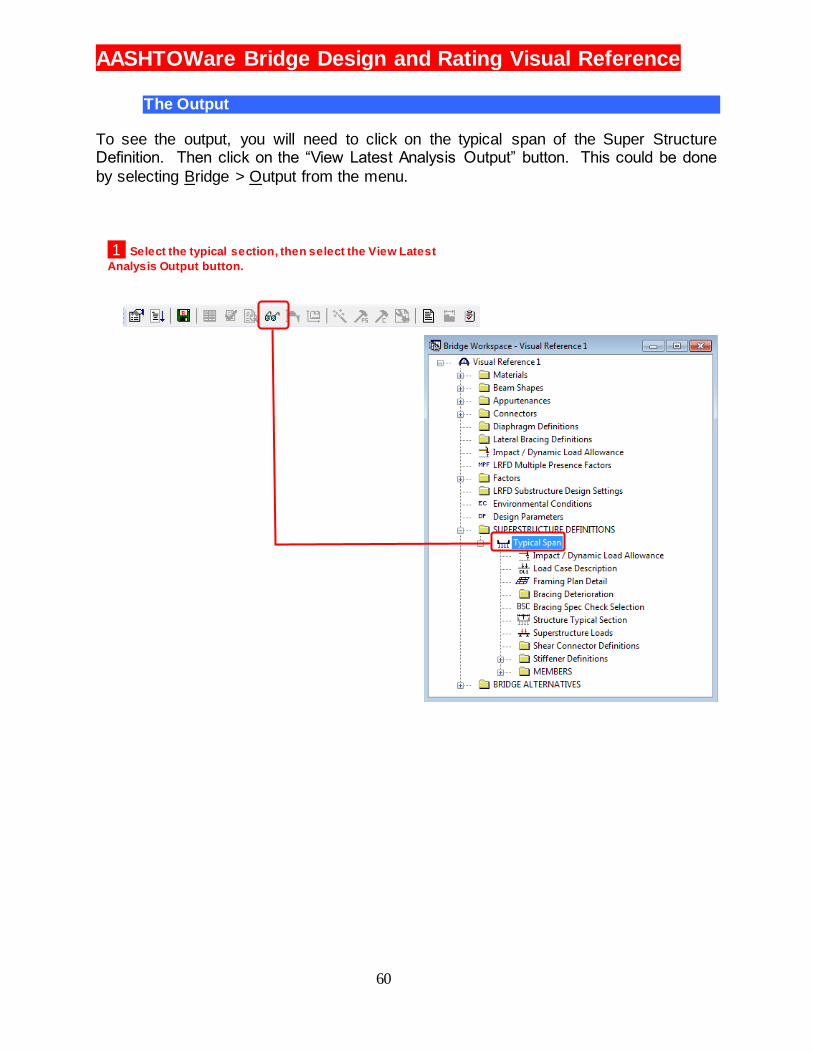
The Output
To see the output, you will need to click on the typical span of the Super Structure Definition. Then click on the “View Latest Analysis Output” button. This could be done
by selecting Bridge > Output from the menu.
1 Select the typical section, then select the View Latest
Analysis Output button.
AASHTOWare Bridge Design and Rating Visual Reference
61
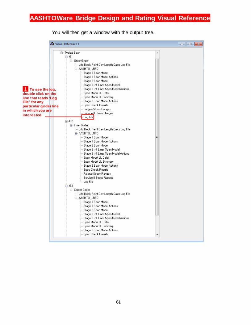
You will then get a window with the output tree.
1 To see the log,
double click on the
line that reads ‘Log File’ for any
particular girder line
in which you are
interested
AASHTOWare Bridge Design and Rating Visual Reference
62
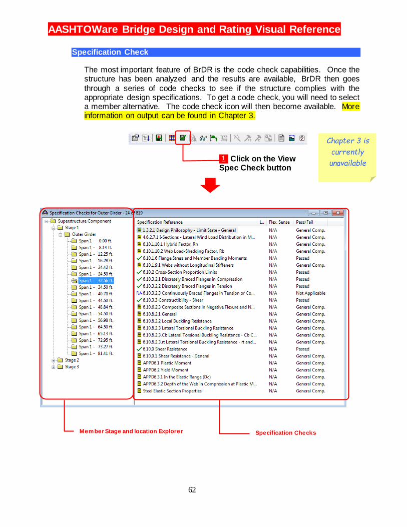
Specification Check
The most important feature of BrDR is the code check capabilities. Once the structure has been analyzed and the results are available, BrDR then goes
through a series of code checks to see if the structure complies with the appropriate design specifications. To get a code check, you will need to select a member alternative. The code check icon will then become available. More information on output can be found in Chapter 3.
Enter Accept
changes and
keep
working
Reject
changes and
close dialog
box
Accept
changes and
close dialog
box
1 Click to
expand
material list
2 Double
click to enter
steel
material
3 Click
Copy from
Library to
get steel
material
4 Doubleclick
the
appropriate
material, in
this case
1936 to 1963
steel
5 Results 1 and 2 Click both to
expand Steel
Beam
3 Doubleclick I
Shapes to
enter data
for our beam
4 Click
Copy from
Library to
get steel
material
5 To start
search, type
‘36WF’
6 Select
Standard for
standard
beam
shapes
7 Select
correct
shape from
list
8 Click OK 9 Results Resulting
Bridge
Workspace
tree
1 Click to
expand
Appurtenanc
es
3 Enter the
railing as
shown here
4 Click OK
to accept
values
2 Double
click Railing
to create a
railing
Select for
most
designs
For LRFD
design.
Default
values
should be
fine for most
designs
For ASD or
LFD design
1 Click on the View Spec Check button
Member Stage and location Explorer Specification Checks
Chapter 3 is
currently
unavailable
Related Documents