BRAVA Cod. F07010461 2006-05 MASCHIO GASPARDO S.p.A. *) USO E MANUTENZIONE / PARTI DI RICAMBIO USE AND MAINTENANCE / SPARE PARTS EMPLOI ET ENTRETIEN / PIECES DETACHEES GEBRAUCH UND WARTUNG / ERSATZTEILE EMPLEO Y MANTENIMIENTO / PIEZAS DE REPUESTO IT EN FR DE ES *) Valido per Paesi UE *) Valid for EU member countries *) Valable dans les Pays UE *) Gilt für EU-Mitgliedsländer *) Válido para Países UE

Welcome message from author
This document is posted to help you gain knowledge. Please leave a comment to let me know what you think about it! Share it to your friends and learn new things together.
Transcript

BRAVACod. F07010461 2006-05
MASCHIO GASPARDO S.p.A.*)
USO E MANUTENZIONE / PARTI DI RICAMBIOUSE AND MAINTENANCE / SPARE PARTSEMPLOI ET ENTRETIEN / PIECES DETACHEESGEBRAUCH UND WARTUNG / ERSATZTEILEEMPLEO Y MANTENIMIENTO / PIEZAS DE REPUESTO
IT
EN
FR
DE
ES
*) Valido per Paesi UE*) Valid for EU member countries*) Valable dans les Pays UE*) Gilt für EU-Mitgliedsländer*) Válido para Países UE

ITALIANO ENGLISH FRANÇAIS ESPAÑOLDEUTSCH
2
1.0 IDENTIFICAZIONEOgni singola macchina, è dotata di unatarghetta di identificazione (A pagina 9),i cui dati riportano:
1) Indirizzo del Costruttore.2) Tipo della macchina.3) Modello della macchina.4) Numero di matricola.5) Anno di costruzione.6) Peso standard.
Si consiglia di trascrivere i propri datisulla matricola qui sotto rappresenta-ta con la data di acquisto (7) ed il nomedel concessionario (8).
1.0 IDENTIFICATIONEach individual machine has an identifi-cation plate (A page 9) indicating the fol-lowing details:
1) The Manufacturer’s address.2) Machine type.3) Machine model.4) Serial number.5) Year of manufacture.6) Standard weight.
You are advised to note down yourdata on the form below, along with thedate of purchase (7) and the dealer’sname (8).
1.0 IDENTIFIZIERUNGJedes Gerätes ist mit einem Typenschildversehen (A Seite 9), auf dem die folgen-den Daten stehen:
1) Anschrift des Herstellers.2) Typ des Gerätes.3) Modell des Gerätes.4) Serien-Nummer.5) Baujahr.6) Standardgewicht.
Die Kenndaten der eigenen Maschinen,die auf dem Typenschild stehen, soll-ten hier unten eingetragen werden. Siebestehen aus dem Kaufdatum (7) unddem Namen des Vertragshändlers (8).
1.0 IDENTIFICATIONChaque machine est identifiée par uneplaque (A page 9) sur laquelle sont indi-qués:
1) Adresse du Constructeur.2) Type de la machine.3) Modèle de la machine.4) Numéro de série.5) Année de fabrication.6) Poids standard.
Il est conseillé d’écrire vos coordon-nées sur le talon représenté ci-des-sous avec la date d’achat (7) et le nomdu concessionnaire (8).
1.0 IDENTIFICACIONCada máquina posee una placa de iden-tificación (A pagína 9). Que exponen lossiguientes datos:
1) Dirección de la fabrica constructora.2) Tipo de máquina.3) Modelo de máquina.4) Número de matrícula.5) Año de fabricación.6) Peso estándar.
Se recomienda anotar los propiosdatos en la ficha que abajo se mues-tra con la fecha de compra (7) y elnombre del concesionario (8).
(8)
(7)
(2)
(3)
(4)
(6)
(5)
(1)

3
ITALIANO ENGLISH FRANÇAIS ESPAÑOLDEUTSCH
INDICE
1.0 IDENTIFICAZIONE ..................... 21.1 Dati tecnici
(mod. fisso) ................................. 41.2 Dati tecnici
(mod. spostabile) ......................... 61.3 Premessa .................................... 81.4 Segnali di avvertenza ................ 101.5 Segnali di pericolo ..................... 101.6 Segnali di indicazione ............... 111.7 Garanzia .................................... 111.8 Scadenza della garanzia ........... 11
2.0 NORME DI SICUREZZA EPREVENZIONE INFORTUNI ..... 12
3.0 NORME D'USO ........................ 193.1 Trasporto ................................... 193.2 Macchine fornite parzialmente
montate ..................................... 213.3 Prima dell'uso ............................ 213.4 Applicazione al trattore ............. 223.5 Verifica capacità di sollevamento
e stabilità della trattriceabbinata alla macchina ............. 24
3.6 Albero cardanico ....................... 253.7 Modalità di trasporto ................. 273.8 Regolazione dell’altezza
di lavoro ..................................... 273.9 Coltelli ........................................ 273.10 Sostituzione dei coltelli .............. 293.11 Trasmissione laterale ................ 313.12 Sostituzione cinghie .................. 323.13 Spostamento ............................. 323.14 Spostamento meccanico ........... 333.15 Spostamento idraulico .............. 333.16 Modello fisso ............................. 343.17 Accessori optional ..................... 343.18 Regolazione denti di raccolta .... 363.19 Rullo a due posizioni ................. 363.20 In lavoro ..................................... 373.21 Come si lavora .......................... 383.22 Consigli utili per il trattorista ...... 413.23 Parcheggio ................................. 42
4.0 MANUTENZIONE .................... 434.1 Prime 8 ore lavorative ................ 444.2 Ogni 8 ore lavorative ................. 444.3 Ogni 50 ore lavorative ............... 444.4 Ogni 400 ore lavorative ............. 444.5 Messa a riposo .......................... 444.6 Lubrificazione ............................ 464.7 Tabella riassuntiva di
manutenzione ............................ 474.8 Inconvenienti e cause ............... 48
5.0 PARTI DI RICAMBIO ................. 51
INDEX
1.0 IDENTIFICATION ........................ 21.1 Technical data
(fixed model) ............................... 41.2 Technical data
(adjustable model) ....................... 61.3 Foreword ..................................... 81.4 Warning signals ......................... 101.5 Danger signals .......................... 101.6 Indicator signals ........................ 111.7 Warranty .................................... 111.8 Warranty becomes void ............ 11
2.0 SAFETY AND ACCIDENTPREVENTING PROVISIONS .... 12
3.0 USE INSTRUCTIONS ............. 193.1 Transport ................................... 193.2 Machines supplied partly
broken-down ............................. 213.3 Before use ................................. 213.4 Hitching to the tractor ................ 223.5 Check the lifting capacity
and stability of the tractor towhich the machine is hitched .... 24
3.6 Cardan shaft .............................. 253.7 Transport method ...................... 273.8 Adjustment of working height .... 273.9 Blades ....................................... 273.10 Replacing blades ....................... 293.11 Side transmission ...................... 313.12 Replacing the belts .................... 323.13 Shifting ...................................... 323.14 Mechanical shifting .................... 333.15 Hydraulic shifting ....................... 333.16 Fixed model ............................... 343.17 Optional accesories ................. 343.18 Adjustment of collector teeth .... 363.19 Two-position movement ............ 363.20 In work ....................................... 373.21 How to works ............................. 383.22 Useful advice for tractor driver ..... 413.23 Parking ...................................... 42
4.0 MAINTENANCE ....................... 434.1 First 8 hours service .................. 444.2 Every 8 work hours .................... 444.3 Every 50 hours service .............. 444.4 Every 400 hours service ............ 444.5 Storage ...................................... 444.6 Lubrication ................................. 464.7 Maintenance recapitulatory
chart .......................................... 474.8 Inconveniences and causes ...... 49
5.0 SPARE PARTS ........................ 51
INHALT
1.0 IDENTIFIZIERUNG ..................... 21.1 Technische Daten
(Feste modell) ............................. 41.2 Technische Daten
(Verschiebbarre modell) .............. 61.3 Vorwort ........................................ 81.4 Warnsignale .............................. 101.5 Gefahrsignale ............................ 101.6 Anzeigesignale .......................... 111.7 Garantie .................................... 111.8 Garantieverfall ........................... 11
2.0 SICHERHEITS UNDUNFALLVERHÜTUNGS-BESTIMMUNGEN .................... 12
3.0 BETRIEBS ANLEITUNG ......... 193.1 Transport ................................... 193.2 Teilweise montiert gelieferte
maschinen ................................. 213.3 Vor der inbetriebnahme ............. 213.4 Anbringung am schlepper ......... 223.5 Prüfung der hubkraft und
standsicherheit des mit dermaschine verbundenentraktors .... 24
3.6 Gelenkwelle ............................... 253.7 Transportmodalitäten ................ 273.8 Einstellung der Arbeitshöhe ...... 273.9 Messer ....................................... 273.10 Auswechseln der Messer .......... 293.11 Seitlicher Antrieb ....................... 313.12 Wechsel der Riemen ................. 323.13 Verstellung ................................ 323.14 Mechanische Verstellung .......... 333.15 Hydraulische Verstellung .......... 333.16 Festes modell ............................ 343.17 Optionales Zubehör .................. 343.18 Einstellung der Zahnserie zum
Aufsammeln .............................. 363.19 Walze mit zwei positionen ......... 363.20 Bei der arbeit ............................. 373.21 Wie man mit der Maschine
Arbeitet ...................................... 383.22 Ratschläge für den Lenker ........ 413.23 Parken ....................................... 42
4.0 WARTUNG ............................... 434.1 Erste 8 betriebsstunden ............ 444.2 Alle 8 betriebsstunden ............... 444.3 Alle 50 betriebsstunden ............. 444.4 Alle 400 betriebsstunden........... 444.5 Ruheperioden ............................ 444.6 Schmierdienst ............................ 464.7 Tabelle zusammenfassend
der wartung ............................... 474.8 Störungen un deren ursachen ... 50
5.0 ERSATZTEILE ......................... 51
TABLE DES MATIERES
1.0 IDENTIFICATION ........................ 21.1 Caractéristiques techniques
(model fixe) .................................. 41.2 Caractéristiques techniques
(model deportable) ....................... 61.3 Introduction ................................. 81.4 Signaux de recomandation ....... 101.5 Signaux de danger .................... 101.6 Signaux d'indication .................. 111.7 Garantie .................................... 111.8 Expiration de la garantie ........... 11
2.0 CONSIGNES DE SÉCURITÉET DE PREVENTION DESACCIDENTS ............................ 12
3.0 UTILISATION ........................... 193.1 Transport ................................... 193.2 Machines fournies en partie
demontees ................................ 213.3 Avant utilisation ......................... 213.4 Attelage au tracteur ................... 223.5 Controle des capacités de
levage et stabilité du tracteurrelié a la machine ...................... 24
3.6 Arbre a cardans ......................... 253.7 Mode de transport ..................... 273.8 Reglage de la hauteur de travail ... 273.9 Lames ........................................ 273.10 Changement des lames ............ 293.11 Transmission laterale ................ 313.12 Changement des courroies ....... 323.13 Deplacement ............................. 323.14 Deplacement mecanique .......... 333.15 Deplacement hydraulique ......... 333.16 Modele fixe ................................ 343.17 Accessoires optionnels .............. 343.18 Reglage des dents de
ramassage ................................. 363.19 Deplacement a deux positions .... 363.20 Execution du travail ................... 373.21 Comment travailler avec
la machine ................................. 383.22 Conseils utiles pour le tractoriste .... 413.23 Stationnement ........................... 42
4.0 ENTRETIEN ............................. 434.1 Apres les 8 premieres heures
de travail .................................... 444.2 Toutes les 8 heures de travail ..... 444.3 Toutes les 50 heures de travail ..... 444.4 Toutes les 400 heures de travail .... 444.5 Remissage ................................ 444.6 Lubrification ............................... 464.7 Tableau récapitulatif de
entretien .................................... 474.8 Inconvénients et causes ............ 49
5.0 PIECES DÉTACHÉES ............. 51
INDICE
1.0 IDENTIFICACIÓN ....................... 21.1 Datos técnicos (model fija) .......... 41.2 Datos técnicos
(model desplazables) .................. 61.3 Consideraciones ......................... 81.4 Señales de advertencia ............ 101.5 Señales de peligro .................... 101.6 Señales de indicacion ............... 111.7 Garantía .................................... 111.8 Vencimiento de la garantía ....... 11
2.0 NORMAS DE SEGURIDADY PREVENCIONACCIDENTES .......................... 12
3.0 NORMAS DE USO .................. 193.1 Transporte ................................. 193.2 Maquinas suministradas
parcialmente montadas ............. 213.3 Antes del uso ............................ 213.4 Aplicacion al tractor ................... 223.5 Control de la capacidad de
elevación y la estabilidad deltractor enganchado enla máquina ................................. 24
3.6 Arbol cardanico ......................... 253.7 Modalidad de transporte ........... 273.8 Regulación de la altura
de trabajo .................................. 273.9 Cuchillas .................................... 273.10 Sostitución de las cuchillas ....... 293.11 Transmissión lateral .................. 313.12 Sostitución de las correas ......... 323.13 Desplazamiento ........................ 323.14 Desplazamiento mecánico ........ 333.15 Desplazamiento hidráulico ........ 333.16 Modelo fijo ................................. 343.17 Acesorios opcionales ................ 343.18 Regulación de los dientes
de recollección .......................... 363.19 Rodillo de dos posiciones ......... 363.20 En funcionamiento .................... 373.21 Como se trabaja ........................ 383.22 Consejos utiles para el tractorista ... 413.23 Aparcamiento ............................ 42
4.0 MANTENIMIENTO ................... 434.1 Primeras 8 horas de trabajo ...... 444.2 Cada 8 horas de trabajo ............ 444.3 Cada 50 horas de trabajo .......... 444.4 Cada 400 horas de trabajo ........ 444.5 Periodos de reposo ................... 444.6 Lubricacion ................................ 464.7 Tablas recopilativo
de manteniemiento .................... 474.8 Inconvenientes y causas ........... 50
5.0 PIEZAS DE REPUESTO ......... 51
ITALIANO ENGLISH FRANÇAIS ESPAÑOLDEUTSCH
4
60 60
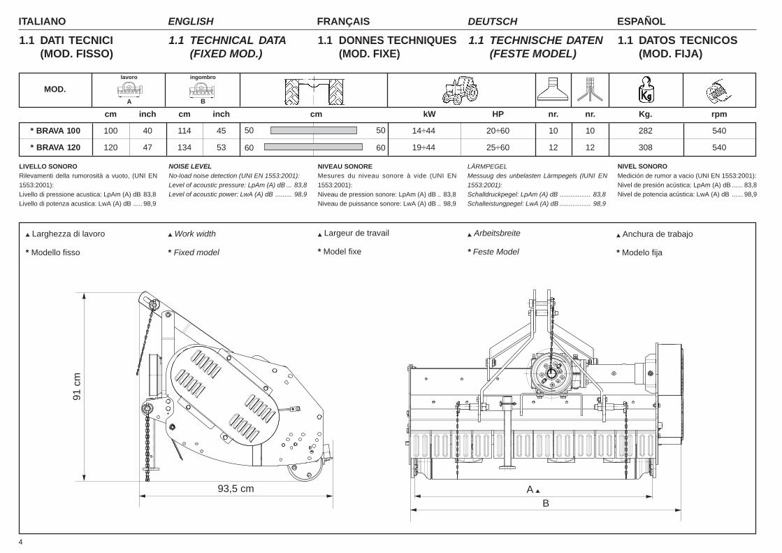
1.1 DATI TECNICI(MOD. FISSO)
1.1 TECHNICAL DATA(FIXED MOD.)
1.1 TECHNISCHE DATEN(FESTE MODEL)
1.1 DONNES TECHNIQUES(MOD. FIXE)
1.1 DATOS TECNICOS(MOD. FIJA)
91 c
m
93,5 cm A B
LIVELLO SONORORilevamenti della rumorosità a vuoto, (UNI EN1553:2001):Livello di pressione acustica: LpAm (A) dB 83,8Livello di potenza acustica: LwA (A) dB ..... 98,9
NOISE LEVELNo-load noise detection (UNI EN 1553:2001):Level of acoustic pressure: LpAm (A) dB ... 83,8Level of acoustic power: LwA (A) dB ......... 98,9
LÄRMPEGELMessuug des unbelasten Lärmpegels (IUNI EN1553:2001):Schalldruckpegel: LpAm (A) dB ................. 83,8Schalleistungpegel: LwA (A) dB ................. 98,9
NIVEAU SONOREMesures du niveau sonore à vide (UNI EN1553:2001):Niveau de pression sonore: LpAm (A) dB .. 83,8Niveau de puissance sonore: LwA (A) dB .. 98,9
NIVEL SONOROMedición de rumor a vacio (UNI EN 1553:2001):Nivel de presión acústica: LpAm (A) dB ...... 83,8Nivel de potencia acústica: LwA (A) dB ...... 98,9
* BRAVA 100 100 40 114 45 14÷44 20÷60 10 10 282 540
* BRAVA 120 120 47 134 53 19÷44 25÷60 12 12 308 540
50 50
MOD.A B
lavoro ingombro
cm inch cm inch cm kW HP nr. nr. Kg. rpm
Larghezza di lavoro Work width Arbeitsbreite Anchura de trabajo Largeur de travail
* Modello fisso * Fixed model * Feste Model * Modelo fija* Model fixe
5
ITALIANO ENGLISH FRANÇAIS ESPAÑOLDEUTSCH
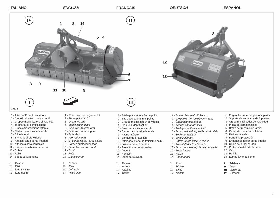
1 - Attacco 3° punto superiore 2 - Castello di attacco ai tre punti 3 - Gruppo moltiplicatore di velocità 4 - Targhetta di identificazione 5 - Braccio trasmissione laterale 6 - Carter trasmissione laterale 7 - Slitte laterali 8 - Bandelle di protezione 9 - Attacchi terzo punto inferiori10 - Attacco albero cardanico11 - Protezione albero cardanico12 - Cofano13 - Rullo14 - Staffa sollevamento
I DavantiII DietroIII Lato sinistroIV Lato destro
1 - Enganche de tercer punto superior 2 - Soporte de enganche de 3 puntos 3 - Grupo multiplicador de velocidad 4 - Placa de características 5 - Brazo de transmisión lateral 6 - Cárter de transmisión lateral 7 - Patines laterales 8 - Banda de protección 9 - Enganches tercer punto inferior10 - Unión del árbol cardán11 - Protección del árbol cardán12 - Capot13 - Rodillo14 - Estribo levantamiento
I AdelanteII AtrasIII IzquierdaIV Derecha
1 - 3rd connection, upper point 2 - Three point hitch 3 - Overdrive unit 4 - Identification plate 5 - Side transmission arm 6 - Side transmission guard 7 - Side skids 8 - Protection bars 9 - 3rd connections, lower points10 - Cardan shaft connection11 - Protection cardan shaft12 - Cowl13 - Roller14 - Lifting stirrup
I In frontII RearIII Left sideIV Right side
1 - Attelage supérieur 3ème point 2 - Bâti d’attelage à trois points 3 - Groupe multiplicateur de vitesse 4 - Plaque d’identification 5 - Bras transmission latérale 6 - Carter transmission latérale 7 - Patins latéraux 8 - Bandes de protection 9 - Attelages inférieurs troisième point10 - Fixation arbre à cardan11 - Protection arbre à cardan12 - Auvent13 - Hérisson14 - Etrier de relevage
I DevantII ArriéreIII GaucheIV Droite
I
IV II
IIIFig. 1
1 - Oberer Anschluß 3° Punkt 2 - Dreipunkt - Anschlußvorrichtung 3 - Übersetzungsgetriebe 4 - Kennzeichnungsschild 5 - Ausleger seitlicher Antrieb 6 - Schutzverkleidung seitlicher Antrieb 7 - Seitliche Schlitten 8 - Schutzblenden 9 - Untere Anschlüsse 3° Punkt10 - Anschluß der Kardanwelle11 - Schutzverkleidung der Kardanwelle12 - Feste haube13 - Walze14 - Hebebuegel
I VornII HintenIII LinksIV Rechts
8
1 2
45
67
9
911 10
12
13
3
14
ITALIANO ENGLISH FRANÇAIS ESPAÑOLDEUTSCH
6
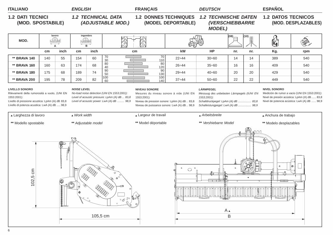
1.2 DATI TECNICI(MOD. SPOSTABILE)
1.2 TECHNICAL DATA(ADJUSTABLE MOD.)
1.2 TECHNISCHE DATEN(VERSCHIEBBARREMODEL)
1.2 DONNES TECHNIQUES(MODEL DEPORTABLE)
1.2 DATOS TECNICOS(MOD. DESPLAZABLES)
102,
5 cm
105,5 cmA
B
LIVELLO SONORORilevamenti della rumorosità a vuoto, (UNI EN1553:2001):Livello di pressione acustica: LpAm (A) dB 83,8Livello di potenza acustica: LwA (A) dB ..... 98,9
NOISE LEVELNo-load noise detection (UNI EN 1553:2001):Level of acoustic pressure: LpAm (A) dB ... 83,8Level of acoustic power: LwA (A) dB ......... 98,9
LÄRMPEGELMessuug des unbelasten Lärmpegels (IUNI EN1553:2001):Schalldruckpegel: LpAm (A) dB ................. 83,8Schalleistungpegel: LwA (A) dB ................. 98,9
NIVEAU SONOREMesures du niveau sonore à vide (UNI EN1553:2001):Niveau de pression sonore: LpAm (A) dB .. 83,8Niveau de puissance sonore: LwA (A) dB .. 98,9
NIVEL SONOROMedición de rumor a vacio (UNI EN 1553:2001):Nivel de presión acústica: LpAm (A) dB ...... 83,8Nivel de potencia acústica: LwA (A) dB ...... 98,9
** BRAVA 140 140 55 154 60 22÷44 30÷60 14 14 389 540
** BRAVA 160 160 63 174 68 26÷44 35÷60 16 16 409 540
** BRAVA 180 175 68 189 74 29÷44 40÷60 20 20 429 540
** BRAVA 200 195 78 209 82 37÷44 50÷60 22 22 449 540
70 7030 11080 8040 12090 9050 130
100 10060 140
MOD.A B
lavoro ingombro
cm inch cm inch cm kW HP nr. nr. Kg. rpm
Larghezza di lavoro Work width Arbeitsbreite Anchura de trabajo Largeur de travail
** Modello spostabile ** Adjustable model ** Vershiebarre Model ** Modelo desplazables** Model déportable
(08) (10)
7
ITALIANO ENGLISH FRANÇAIS ESPAÑOLDEUTSCH
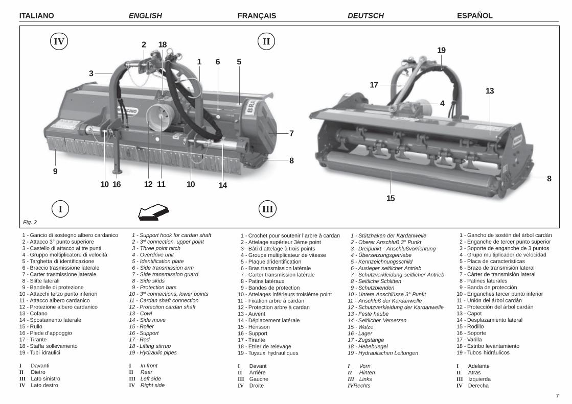
1 - Gancio di sostegno albero cardanico 2 - Attacco 3° punto superiore 3 - Castello di attacco ai tre punti 4 - Gruppo moltiplicatore di velocità 5 - Targhetta di identificazione 6 - Braccio trasmissione laterale 7 - Carter trasmissione laterale 8 - Slitte laterali 9 - Bandelle di protezione10 - Attacchi terzo punto inferiori11 - Attacco albero cardanico12 - Protezione albero cardanico13 - Cofano14 - Spostamento laterale15 - Rullo16 - Piede d’appoggio17 - Tirante18 - Staffa sollevamento19 - Tubi idraulici
I DavantiII DietroIII Lato sinistroIV Lato destro
1 - Gancho de sostén del árbol cardán 2 - Enganche de tercer punto superior 3 - Soporte de enganche de 3 puntos 4 - Grupo multiplicador de velocidad 5 - Placa de características 6 - Brazo de transmisión lateral 7 - Cárter de transmisión lateral 8 - Patines laterales 9 - Banda de protección10 - Enganches tercer punto inferior11 - Unión del árbol cardán12 - Protección del árbol cardán13 - Capot14 - Desplazamiento lateral15 - Rodillo16 - Soporte17 - Varilla18 - Estribo levantamiento19 - Tubos hidráulicos
I AdelanteII AtrasIII IzquierdaIV Derecha
1 - Support hook for cardan shaft 2 - 3rd connection, upper point 3 - Three point hitch 4 - Overdrive unit 5 - Identification plate 6 - Side transmission arm 7 - Side transmission guard 8 - Side skids 9 - Protection bars10 - 3rd connections, lower points11 - Cardan shaft connection12 - Protection cardan shaft13 - Cowl14 - Side move15 - Roller16 - Support17 - Rod18 - Lifting stirrup19 - Hydraulic pipes
I In frontII RearIII Left sideIV Right side
1 - Crochet pour soutenir l’arbre à cardan 2 - Attelage supérieur 3ème point 3 - Bâti d’attelage à trois points 4 - Groupe multiplicateur de vitesse 5 - Plaque d’identification 6 - Bras transmission latérale 7 - Carter transmission latérale 8 - Patins latéraux 9 - Bandes de protection10 - Attelages inférieurs troisième point11 - Fixation arbre à cardan12 - Protection arbre à cardan13 - Auvent14 - Déplacement latérale15 - Hérisson16 - Support17 - Tirante18 - Etrier de relevage19 - Tuyaux hydrauliques
I DevantII ArriéreIII GaucheIV Droite
I
IV II
IIIFig. 2
1 - Stützhaken der Kardanwelle 2 - Oberer Anschluß 3° Punkt 3 - Dreipunkt - Anschlußvorrichtung 4 - Übersetzungsgetriebe 5 - Kennzeichnungsschild 6 - Ausleger seitlicher Antrieb 7 - Schutzverkleidung seitlicher Antrieb 8 - Seitliche Schlitten 9 - Schutzblenden10 - Untere Anschlüsse 3° Punkt11 - Anschluß der Kardanwelle12 - Schutzverkleidung der Kardanwelle13 - Feste haube14 - Seitlicher Versetzen15 - Walze16 - Lager17 - Zugstange18 - Hebebuegel19 - Hydraulischen Leitungen
I VornII HintenIII LinksIVRechts
1 6 5
7
8
89
16 1112 10 14
2
10
15
13
19
17
4
3
18
ITALIANO ENGLISH FRANÇAIS ESPAÑOLDEUTSCH
8
1.3 PREMESSAQuesto opuscolo descrive le normed'uso, di manutenzione e parti che ven-gono fornite di ricambio.La trinciatrice, in seguito chiamata anchemacchina o attrezzatura, è utilizzata pereffettuare operazioni di manutenzione diaree verdi, o trinciatura direttamente sulcampo, mediante lavorazioni disminuzzamento di residui vegetali, siaerbacei che legnosi.La macchina è destinata ad una utenzaprofessionale, se ne consente l’utilizzoai soli operatori specializzati.Non è consentito l’uso da parte di mino-ri, analfabeti, persone in condizione fisi-che o psichiche alterate.Non è consentito l’uso a personale sprov-visto di patente di guida adeguata o nonsufficientemente informato ed addestrato.L’operatore è responsabile del controllodella funzionalità della macchina, la so-stituzione e la riparazione delle parti sog-gette ad usura che potrebbero causaredanni.Questa attrezzatura agricola, può ope-rare solo tramite un albero cardanicoapplicato alla presa di forza di un trattoreagricolo munito di gruppo sollevatore, conattacco universale ai tre punti.Dal corretto uso e dall'adeguata manu-tenzione dipende il regolare funziona-mento dell'attrezzatura.È consigliabile quindi, osservare scrupo-losamente quanto descritto allo scopo diprevenire un qualsiasi inconveniente chepotrebbe pregiudicare il buon funziona-mento e la sua durata.È altresì importante attenersi a quantodescritto nel presente opuscolo in quan-to la Ditta Costruttrice declina ogni equalsiasi responsabilità dovuta a ne-gligenza ed alla mancata osservanzadi tali norme.La Ditta Costruttrice, è comunque a com-pleta disposizione per assicurare un'im-mediata e accurata assistenza tecnica etutto ciò che può essere necessario peril miglior funzionamento e la massimaresa dell'attrezzatura.
1.3 FOREWORDThis handbook describes the use, main-tenance instructions and spare parts sup-plied.The shredder, hereinafter referred asmachine or equipment, is used for themaintenance of green areas and fields;it shreds vegetable and wooden residues.The machine is dedicated to a profes-sional user. Only specialized workersshould be allowed to use it.Persons under age, illiterate persons orthose with physical or mental disordersare not allowed to use the machine.Only persons holding adequate drivinglicenses must be allowed to use the ma-chine after having been sufficiently in-formed and trained.The Operator is responsible for makingsure that the machine is functional andfor replacing and repairing parts liable towear that could otherwise cause damage.The farming implement can only operatethrough the cardan shaft fitted to the ptoof a farming tractor equipped with lift anduniversal 3-point coupling.Regular and satisfactory operation to-gether with economic and long-lastinguse of the implement depend on compli-ance with the instructions given in thishandbook. It is therefore advisable tostrictly comply with the following instruc-tions in order to prevent faults which couldjeopardize the correct and long-lastingoperation of the implement.Compliance with the instructions in thishandbook is also important since theManufacturer declines all and everyresponsibility for damage to personsor property caused by negligence andfailure to comply with these instruc-tions.The Manufacturer shall, however, remainat the customers’ disposal for immediateand thorough assistance together withanything else that may be required in or-der to ensure the correct operation andmaximum efficiency of the implement.
1.3 VORWORTDieses Heft enthält die Betriebs- undWartungsanleitung, sowie die Liste derErsatzteile, die geliefert werden.Das Mulchgerät, dann auch Maschineoder Ausrüstung genannt, wird für Unter-haltungsarbeiten der grünen Räume be-nutzt oder auch direkt auf dem feld durchZerkleinerungen des pflanzlichen, gras-artigen und hölzernen Rückstand.Die Maschine ist für den gewerblichenGebrauch bestimmt, so daß sie nur durchspezialisiertes Personal benutzt werdendarf.Die Benutzung durch Unmündige, An-alphabeten, Personen mit körperlichenoder seelischen Störungen ist unzulässig.Die Benutzung durch Personal ohne an-gemessenen Führerschein oder durchPersonal, das nicht ausreichend infor-miert und geschult ist, ist unzulässig.Der Fahrer ist für die Kontrolle der Funk-tionstüchtigkeit der Maschine, das Erset-zen oder Reparieren der angenutztenTeile zuständig, die Schäden verursa-chen könnten.Dieses landwirtschaftliche Gerät, kannnur über die Gelenkwelle angetriebenwerden, die an der Zapfwelle einesSchleppers mit Kraftheber und universel-ler Dreipunkt-Kupplung angeschlossenwird. Von korrektem Gebrauch und sach-gerechter Wartung hängt es daher ab, obSie lange Freude an Ihres Gerät haben.Die sorgfältige Beachtung der in dieserBroschüre beschriebenen Anleitungen istdaher empfehlenswert, um alle Störun-gen zu vermeiden, die sich negativ aufden störungsfreien Betrieb und die lan-ge Haltbarkeit des Gerätes auswirken.Die Beachtung dessen, was in dieserBroschüre beschrieben ist, ist auch des-halb wichtig, weil die Hersteller-haftungbei Nachlässigkeit oder Nichtbeach-tung der in diesem Heft beschriebe-nen Vorschriften verfällt.Der Hersteller steht auf jeden Fall zurVerfügung, um einen prompten und ak-kuraten Kundendienst zu liefern, wieauch all das, was erforderlich ist, damitdas Gerät richtig und wirtschaftlich funk-tioniert.
1.3 INTRODUCTIONCette brochure décrit les normes d’utili-sation, d’entretien et pièces détachéeslivrées.Le broyeur; dorénavant appelé machineou équipement, est employé pour l’en-tretien des espaces verts et des champs;il hache les résidus vegétaux et ligneux.La machine est destinée à un usage pro-fessionnel, seuls les opérateurs spécia-lisés sont autorisés à l’utiliser.L’utilisation est interdite aux mineurs,analphabètes, personnes en conditionsphysiques ou psychiques altérées.L’utilisation est interdite au personneln’ayant pas le permis de conduire appro-prié ou non suffisamment informé etformé.L’opérateur est responsable du contrôledu fonctionnement de la machine, duremplacement et de la réparation despièces sujettes à usure qui pourraientprovoquer des dégâts.Cet outil agricole, ne peut être entraînéque par un arbre à cardans relié à la prisede force d’un tracteur agricole équipé derelevage hydraulique, avec attelage troispoints universel.Une utilisation correcte et un bon entre-tien vous permettront d’avoir toujours unappareil performant. Nous vous con-seillons donc de suivre attentivement tou-tes les instructions pour prévenir les in-convénients quipourraient compro-met-tre le bon fonctionnement et la durée devotre appareil.Il est également important de respecterscrupuleusement les descriptions decette brochure car le Constructeur dé-cline toute responsabilité dans le casde négligence ou de non observationde ces instructions.Le Constructeur est à votre entière dis-position pour vous garantir une assis-tance technique immédiate et tout ce quipeut être nécessaire pour obtenir lemeilleur fonctionnement et un rendementoptimal de votre appareil.
1.3 CONSIDERACIONESEste folleto describe las normas de uso,de mantenimiento y piezas suministra-das como repuestos.La trituradora, llamada de seguidamaquina o equipo, es utilizada por lamanutención de los espacios verdes ycampos; esto equipo tritura los restosvegetales y leñosos.La máquina se ha construido para un usoprofesional, debe utilizarla sólo el perso-nal especializado.Prohibido el uso a menores, analfabetos,personas con problemas físicos osíquicos.Prohibido el uso al personal sin el corres-pondiente permiso de conducir o sin unaadecuada información y preparación.El usuario es responsable del control delfuncionamiento de la máquina, de la sus-titución y reparación de las partes des-gastadas que podrían provocar daños.Este equipo agrícola, puede operar sólomediante árbol cardánico aplicado a latoma de fuerza de un tractor agrícola congrupo elevador, con enganche universalde tres puntos.El funcionamiento regular de la máquinaestá supeditado a un uso correcto y unaadecuada manutención de la misma. Esaconsejable, por lo tanto, observar es-crupulosamente las indicaciones expues-tas en este manual, para prevenir asítodo tipo de inconveniente que puedaperjudicar el buen funcionamiento y ladurabilidad.Es importante por otra parte respetar lasindicaciones del manual ya que el fabri-cante declina todo tipo de responsa-bilidad por problemas debidos a ne-gligencias y a la no observación dedichas normas. El Fabricante, se de-clara a sus órdenes para garantizar unainmediata y precisa asistencia técnica ybrindar todo aquello que pueda ser ne-cesario para un mejor funcionamiento yrendimiento de la máquina.
9
ITALIANO ENGLISH FRANÇAIS ESPAÑOLDEUTSCH
Fig. 3
17
14
21
513 11 8
21
A
64
ETICHETTACERTIFICAZIONE
ENAMA
B
5
9
12 16
21 310
18
22
7
6
19 2020
21
15 18

ITALIANO ENGLISH FRANÇAIS ESPAÑOLDEUTSCH
10
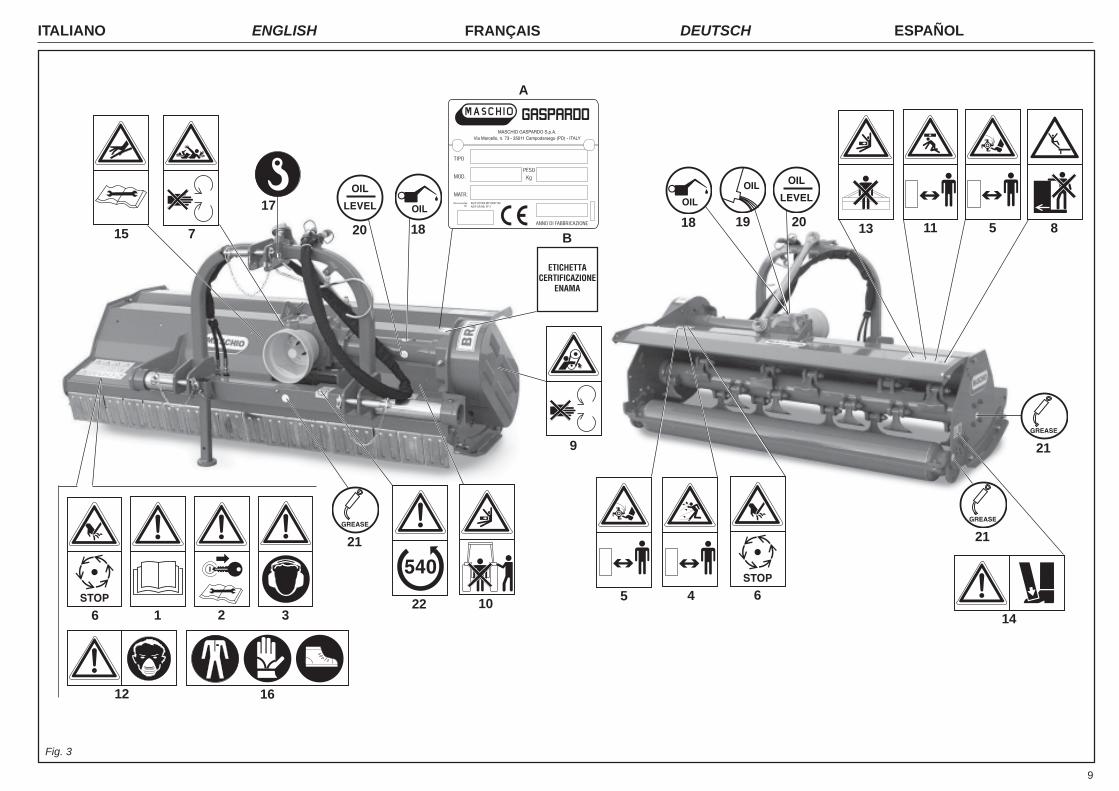
1.4 SEGNALI DIAVVERTENZA
1) Prima di iniziare ad operare, legge-re attentamente il libretto di istruzio-ni.
2) Prima di qualsiasi operazione dimanutenzione e/o registrazione, ar-restare e bloccare il trattore in piano,abbassare la macchina a terra e leg-gere il libretto di istruzioni.
3) Rumorosità elevata. Munirsi di ade-guati strumenti protettivi per l'udito,tipo cuffie.
1.5 SEGNALI DIPERICOLO
4) Pericolo per possibile lancio di og-getti contundenti. Tenersi a distan-za di sicurezza dalla macchina.
5) Pericolo per possibile cesoiamen-to degli arti inferiori. Tenersi a di-stanza di sicurezza dalla macchina.
6) Pericolo di cesoiamento dellemani. Non rimuovere le protezioni enon avvicinarsi con gli organi in mo-vimento.Attendere l’arresto completo degli or-gani in movimento.
7) Pericolo di essere agganciati dal-l'albero cardanico. Non avvicinarsiagli organi in movimento.
8) Pericolo di caduta. Non salire sullamacchina in movimento.
9) Pericolo per possibile cesoiamen-to degli arti superiori. Tenersi a di-stanza di sicurezza dalla macchinain lavoro.
10) Pericolo di schiacciamento. Nonfrapporsi tra la macchina e il trattore.
11) Pericolo di caduta dei cofani dellamacchina. Fare attenzione nell’areacircostante.
12) Pericolo di respirazione di sostan-ze nocive. Munirsi di mascherinaantipolvere nel caso di utilizzo di trat-trice senza cabina e filtri.
13) Pericolo di schiacciamento. Nonstare dietro la macchina.
14) Pericolo per possibile schiaccia-mento degli arti inferiori. Tenersi adistanza di sicurezza dalla macchina.
1.4 WARNING SIGNALS 1) Before operating machine, carefully
read the instruction book. 2) Before any operation of mainte-
nance a/o adjustment, stop, brakethe tractor on level ground, lower themachine to the ground and read theinstruction book.
3) Loud noise. Wear adequate hearingprotection, e.g. headphones.
1.5 DANGER SIGNALS 4) Danger of possible flying blunt
objects. Keep a safe distance fromthe machine.
5) Danger of possible shearing oflower limbs. Keep a safe distancefrom the machine.
6) Danger of injury to the hands.Never remove the guards while theparts are mowing.Wait until all moving componentshave completely stopped.
7) Danger of being hooked by thecardan shaft. Do not go near themembers of the machine while mov-ing.
8) Danger of falling. Do not get up onthe machine while it is moving.
9) Danger of possible shearing ofupper limbs. Keep a safe distancefrom the machine while it is working.
10) Danger of being crushed.Do not get between the tractor andthe machine.
11) Danger: the bonnet could drop.Take care when in the vicinity.
12) Risk of inhaling harmful sub-stances. Wear a dust mask if thetractor is used without cab and filters.
13) Danger of being crushed.Do not get rear the machine.
14) Danger of possible shearing oflower limbs. Keep a safe distancefrom the machine.
1.4 WARNSIGNALE 1) Vor Inbetriebnahme der Maschine
ist vorliegende Gebrauchsanweisungaufmerksam zu lesen.
2) Vor Beginn jeder Art von Wartungs-arbeiten u/o Einstellungen an der Ma-schine, ist der Traktor auf ebener Flä-che anzuhalten und zu blockieren, dieMaschine auf den Boden abzusenkenund die Gebrauchsanweisung zu lesen.
3) Hohe Geräuschbelastung. Es emp-fiehlt sich das Verwenden von geeig-neter Schutzkleidung wie z.B. Ohren-schützer.
1.5 GEFAHRENSIGNALE 4) Auswurfgefahr von stumpfen Ge-
genständen. Aufforderung, bei Ma-schine in Betrieb, einen angemesse-nem Sicherheitsabstand einzuhalten.
5) Gefahr von Amputation der unterenGliedmaßen. Aufforderung, bei Ma-schine in Betrieb, einen angemesse-nem Sicherheitsabstand einzuhalten.
6) Gefahr für Abtrennen der Hände.Bei laufenden Teilen die Schutz-abdeckungen nicht entfernen.Abwarten, dass alle sich bewegen-den Teile vollkommen zum Stehengekommen sind.
7) Gefahr, mit der Kardanwelle ver-klemmt zu werden. Verbot, sich denMaschinenteilen in Bewegung zu nä-hern.
8) Absturzgefahr. Verbot, die Maschi-ne in Betrieb zu besteigen.
9) Gefahr von Amputation der oberenGliedmaßen. Aufforderung, bei Ma-schine in Betrieb, einen angemesse-nem Sicherheitsabstand einzuhalten.
10) Gefahr von Quetschungen: Verbot,sich zwischen Traktor und Maschineaufhalten.
11) Gefahr, daß die Hauben von derMaschine fallen. Auf den Umge-bungsbereich achten.
12) Gefahr des Einatmens schädlicherSubstanzen. Eine Staubschutzmas-ke benutzen, falls der Traktor ohneKabine und Filter benutzt wird.
13) Gefahr von Quetschungen: Verbot,sich hinten Maschine aufhalten.
14) Gefahr von Quetschungen der unte-ren Gliedmaßen. Aufforderung, bei Ma-schine in Betrieb, einen angemessenemSicherheitsabstand einzuhalten.
1.4 SIGNAUXD’AVERTISSEMENT
1) Avant de commencer à opérer, lireattentivement le manuel contenant lemode d’emploi.
2) Avant d’effectuer une opérationd’entretien et/ ou de réglage quel-conque, arrêter le tracteur sur un ter-rain plat et le bloquer, abaisser lamachine au sol, et lire le manuel con-tenant le mode d’emploi.
3) Niveau de bruit élevé. Se munir dedispositifs de protection appropriés,par exemple casque contre le bruit.
1.5 SIGNAUX DE DANGER 4) Danger représenté par le lance-
ment possible d’objets conton-dants. Se tenir à distance de sécu-rité de la machine.
5) Danger représenté par la pressionpossible des membres inférieurs.Se tenir à distance de sécurité de lamachine.
6) Danger de cisaillement des mains.Ne pas démonter les protectionsqund la machine est en marche.Attendre l’arrêt complet des organesen mouvement.
7) Danger d’être accrochés par l’ar-bre à cardan. Ne pas s’approcherdes organes en mouvement.
8) Danger de chute. Ne pas monter surla machine en mouvement.
9) Danger représenté par la pressionpossible des membres supérieurs.Se tenir à distance de sécurité de lamachine en fonctionnement.
10) Danger d’écrasement. Ne pas seplacer entre la machine et le tracteur.
11) Danger de chute des capots de lamachine. Faire attention dans lazone environnante.
12) Danger de respiration de substan-ces nocives.Porter un masque de protection con-tre la poussière en cas d’utilisation dutracteur sans la cabine et les filtres.
13) Danger d’écrasement. Ne pas seplacer arriére la machine.
14) Danger d’écrasement possible desmembres inférieurs. Se tenir à dis-tance de sécurité de la machine.
1.4 SEÑALES DEADVERTENCIA
1) Antes de comenzar a trabajar, leacon suma atención el manual de ins-trucciones.
2) Antes de cualquier operación demantenimiento y/o regulación, parey bloquee el tractor en un lugar pla-no, baje la máquina al suelo y lea elmanual de instrucciones.
3) Ruido elevado. Equípese con ele-mentos de protección del oído ade-cuados, tipo auriculares.
1.5 SEÑALES DE PELIGRO 4) Peligro de posible proyección de
objetos contundentes. Manténga-se a distancia de seguridad de la má-quina.
5) Peligro de posible corte de losmiembros inferiores. Manténgase adistancia de seguridad de la máquina.
6) Peligro de corte para las manos.No quitar las protecciones con los ór-ganos de la méaquina en movimiento.Esperar que los órganos en movi-miento estén completamente para-dos.
7) Peligro de ser enganchado por elárbol cardán. No se acerque a losórganos en movimiento.
8) Peligro de caída. No suba sobre lamáquina en movimiento.
9) Peligro de posible corte de losmiembros superiores. Manténgasea distancia de seguridad de la má-quina en funcionamiento.
10) Peligro de aplastamiento. No se in-terponga entre la máquina y el tractor.
11) Peligro de caída de las proteccio-nes de la máquina. Prestar atencióncerca de la zona.
12) Peligro de respiración de sustan-cias nocivas. Utilizar máscara anti-polvo en caso de empleo del tractorsin cabina o sin filtros.
13) Peligro de aplastamiento. No seatras la máquina.
14) Peligro de posible aplastamientode los miembros inferiores. Man-téngase a distancia de seguridad dela máquina.

11
ITALIANO ENGLISH FRANÇAIS ESPAÑOLDEUTSCH
15) Tubi con fluidi ad alta pressione.In caso di rottura di tubi flessibili fareattenzione al getto d’olio. Leggere illibretto di istruzioni.
1.6 SEGNALI DIINDICAZIONE
16) Munirsi di un’abbigliamento antinfor-tunistico.
17) Punto di aggancio per il sollevamen-to (è indicata la portata max).
18) Tappo per l'introduzione dell'olio.19) Tappo per lo scarico dell'olio.20) Tappo per il controllo dell'olio.21) Punto di ingrassaggio.22) Numero giri presa di forza.A) Targhetta d’identificazione.B) Etichetta certificazione Enama.
1.7 GARANZIAVerificare all'atto della consegna che lamacchina non abbia subito danni duran-te il trasporto e che gli accessori sianointegri e al completo.EVENTUALI RECLAMI DOVRANNOESSERE PRESENTATI PER ISCRITTOENTRO 8 GIORNI DAL RICEVIMENTOPRESSO IL CONCESSIONARIO.L'acquirente potrà far valere i suoi dirittisulla garanzia solo quando egli abbia ri-spettato le condizioni concernenti la pre-stazione della garanzia, riportate nel con-tratto di fornitura.
1.8 SCADENZA DELLAGARANZIA
Oltre a quanto riportato nel contrattodi fornitura, la garanzia decade:- Qualora si dovesse oltrepassare il li-
mite di potenza consentito riportatonella tabella dei dati tecnici a pag. 4-6.
- Qualora, mediante riparazioni esegui-te dall'utilizzatore senza il consensodella Ditta Costruttrice o a causa delmontaggio di pezzi di ricambio non ori-ginali, la macchina dovesse subirecambiamenti e il danno dovesse es-sere causato da tali cambiamenti.
- Qualora non fossero state seguite leistruzioni descritte in questo opuscolo.
15) Pipes with high pressure fluids.Take care if flexible pipes break asoil could spurt. Read the instructionmanual.
1.6 INDICATION SIGNALS16) Wear safety clothing.17) Coupling point for lifting (indicating
the maximun capacity).18) Oil fill plug.19) Oil drain plug.20) Oil level plug.21) Greasing point.22) Number of revolutions of power takeoff.A) Identification plate.B) Enama certification label.
1.7 WARRANTYWhen the machine is delivered, checkthat it has not been subjected to damageduring transport and that the accessoriesare in a perfect condition and complete.ANY CLAIMS FOLLOWING THE RE-CEIPT OF DAMAGED GOODS SHALLBE PRESENTED IN WRITING WITHIN8 DAYS FROM RECEIPT OF THEGOODS THEMSELVES FROM YOURLOCAL DEALER.The purchaser may only make claimsunder guarantee when he has compliedwith the warranty conditions in the sup-ply contract.
1.8 WHEN THE WARRANTYBECOMES VOID
Besides the cases specified in thesupply agreement, the guarantee shallin any case become void:- When the implement has been used
beyond the specified power limit, asgiven in the technical data chart onpage 4-6.
- When, following repairs made by thecustomer without authorization fromthe Manufacturer or owing to installa-tion of spurious spare parts, the ma-chine is subjected to variations and thedamage can be ascribed to these vari-ations.
- When the user has failed to complywith the instructions in this handbook.
15) Schläuche mit unter Hochdruckstehenden Flüssigkeiten. Bei ei-nem Bruch der Schläuche auf aus-spritzendes Öl achten. Lesen Sie dieGebrauchsanleitung durch.
1.6 HINWEISSIGNALE16) Unfallschutzbekleidung tragen.17) Kupplungspunkt zum Ausheben
(max. Tragvermögen ist angegeben).18) Einfüllstopfen Getriebeöl.19) Ablaßstopfen Getriebeöl.20) Ölstandsstopfen Getriebeöl.21) Schmierstellen.22) Umdrehungszahl der Kraftübertragung.A) Typenschield.B) Aufkleber Enama-Zertifizierung.
1.7 GARANTIEBei der Übergabe der Maschine sicher-stellen, daß das Gerät keine Transport-schäden aufweist und alle Zubehörteilevorhanden und unbe-schädigt sind.ETWAIGE REKLAMATIONEN SINDSCHRIFTLICH INNERHALB BINNEN 8TAGEN AB DEM ERHALT BEIMVERTRAGSHÄNDLER.Der Käufer kann seinen Anspruch aufGarantie nur dann geltend machen, wenner sich an die Garantiebedingungen hält,die im Liefervertrag wiedergegeben sind.
1.8 GARANTIEVERFALLDer Garantieanspruch verfällt außer-dem auch immer:- Wenn die zulässigen Leistungsgrenz-
werte überschritten werden, die in derTabelle der technischen Daten aufSeite 4-6 stehen.
- Wenn das Gerät infolge Reparaturen,die der Benutzer ohne die Genehmi-gung des Herstellers ausführen läßt,oder infolge der Verwendung von Er-satzteilen, die kein Original sind, ge-ändert wird und der Schaden auf die-sen Umständen beruht.
- Wenn die in diesem Heft stehendenAnleitungen nicht beachtet wordensind.
15) Tubes avec fluides à haute pres-sion. En cas de rupture des tubesflexibles faire attention au jet d’huile.Lire la notice d’instructions.
1.6 SIGNAUXD’INDICATION
16) Porter des vêtements de sécuritécontre les accidents du travail.
17) Point d'attelage pour le relevage (in-dication de la portée maxi).
18) Bouchon de huile.19) Bouchon de vidange huile.20) Bouchon de niveau huile.21) Point de graissage.22) Nombre de tours de la prise de force.A) Plaque segnalétique.B) Etiquette certification Enama.
1.7 GARANTIEAu moment de la livraison de votre ap-pareil vérifiez qu’il n’a pas été endom-magé pendant le transport et que tousles accessoires sont en bon état.LES RÉCLAMATIONS ÉVENTUELLESDEVRONT ÊTRE PRÉSENTÉES PARÉCRIT DANS UN DÉLAI DE 8 JOURSÀ COMPTER DE LA RÉCEPTION CHEZLE CONCESSIONAIRE.L’acheteur pourra faire valoir ses droitsde garantie uniquement s’il aura respectéles conditions contenues dans le contratde fourniture.
1.8 EXPIRATION DE LAGARANTIE
Lesconditions du contrat de fournituredemeurant valables, la garantie estsupprimée dans les cas suivants:- En cas de dépassement de la limite
de puissance admise (voir tableau desdonnées techniques, page 4-6).
- En cas de réparations effectuées parl’utilisateur sans l’autorisation du Cons-tructeur ou en cas de montage de piè-ces qui ne sont pas d’origine nécessi-tant des modifications qui comporte-raient les dommages constatés.
- En cas de non observation des instruc-tions décrites dans ce guide.
15) Tubos con líquidos a alta presión.En caso de rotura de tubos flexiblesprestar atención a los chorros de acei-te. Leer el manual de instrucciones.
1.6 SEÑALES DEINDICACIÓN
16) Llevar ropa de trabajo adecuada con-tra accidentes.
17) Punto de enganche para el alzamien-to (la capacidad máxima).
18) Tapón introducción aceite.19) Tapón descarga aceite.20) Tapón de nivel aceite.21) Punto de engrase.22) Número de revoluciones de la toma
de fuerza.A) Placa de identificacíon.B) Etiqueta certificación Enama.
1.7 GARANTIAEn el momento de la recepción de lamáquina controlar que no haya sufridodaños por el transporte y que estén to-dos los accesorios en perfecto estado.EVENTUALES RECLAMOS SE DEBE-RÁN PRESENTAR POR ESCRITODENTRO DE LOS 8 DÍAS DEL MOMEN-TO DE RECEPCIÓN EN EL CONCE-SIONARIO.El comprador podrá gozar de la garantíasólo si ha respetado las condiciones re-lativas a la garantía, expuestas en el con-trato de provisión.
1.8 VENCIMIENTO DE LAGARANTIA
Además de los casos previstos en elcontrato de provisión, la garantía pier-de todo valor si:- Si se supera el límite de potencia per-
mitido expuesto en la tabla de los da-tos técnicos de la pág. 4-6.
- Si la máquina sufre modificacionesseguidamente a reparaciones efectua-das por el usuario sin la debida autori-zación o por el montaje de repuestosno originales, y si dichas modificacio-nes provocan averías.
- Por la no observación de las normasque se describen en este manual.
ITALIANO ENGLISH FRANÇAIS ESPAÑOLDEUTSCH
12
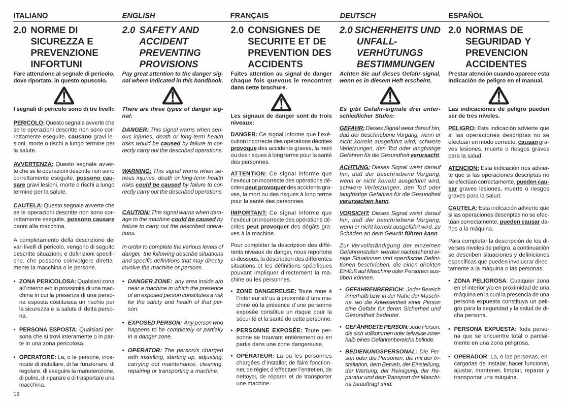
2.0 NORME DISICUREZZA EPREVENZIONEINFORTUNI
Fare attenzione al segnale di pericolo,dove riportato, in questo opuscolo.
I segnali di pericolo sono di tre livelli:
PERICOLO: Questo segnale avverte chese le operazioni descritte non sono cor-rettamente eseguite, causano gravi le-sioni, morte o rischi a lungo termine perla salute.
AVVERTENZA: Questo segnale avver-te che se le operazioni descritte non sonocorrettamente eseguite, possono cau-sare gravi lesioni, morte o rischi a lungotermine per la salute.
CAUTELA: Questo segnale avverte chese le operazioni descritte non sono cor-rettamente eseguite, possono causaredanni alla macchina.
A completamento della descrizione deivari livelli di pericolo, vengono di seguitodescritte situazioni, e definizioni specifi-che, che possono coinvolgere diretta-mente la macchina o le persone.
• ZONA PERICOLOSA: Qualsiasi zonaall’interno e/o in prossimità di una mac-china in cui la presenza di una perso-na esposta costituisca un rischio perla sicurezza e la salute di detta perso-na.
• PERSONA ESPOSTA: Qualsiasi per-sona che si trovi interamente o in par-te in una zona pericolosa.
• OPERATORE: La, o le persone, inca-ricate di installare, di far funzionare, diregolare, di eseguire la manutenzione,di pulire, di riparare e di trasportare unamacchina.
2.0 SAFETY ANDACCIDENTPREVENTINGPROVISIONS
Pay great attention to the danger sig-nal where indicated in this handbook.
There are three types of danger sig-nal:
DANGER: This signal warns when seri-ous injuries, death or long-term healthrisks would be caused by failure to cor-rectly carry out the described operations.
WARNING: This signal warns when se-rious injuries, death or long-term healthrisks could be caused by failure to cor-rectly carry out the described operations.
CAUTION: This signal warns when dam-age to the machine could be caused byfailure to carry out the described opera-tions.
In order to complete the various levels ofdanger, the following describe situationsand specific definitions that may directlyinvolve the machine or persons.
• DANGER ZONE: any area inside a/onear a machine in which the presenceof an exposed person constitutes a riskfor the safety and health of that per-son.
• EXPOSED PERSON: Any person whohappens to be completely or partiallyin a danger zone.
• OPERATOR: The person/s chargedwith installing, starting up, adjusting,carrying out maintenance, cleaning,repairing or transporting a machine.
2.0 CONSIGNES DESECURITE ET DEPREVENTION DESACCIDENTS
Faites attention au signal de dangerchaque fois quevous le rencontrezdans cette brochure.
Les signaux de danger sont de troisniveaux:
DANGER: Ce signal informe que l’exé-cution incorrecte des opérations décritesprovoque des accidents graves, la mortou des risques à long terme pour la santédes personnes.
ATTENTION: Ce signal informe quel’exécution incorrecte des opérations dé-crites peut provoquer des accidents gra-ves, la mort ou des risques à long termepour la santé des personnes.
IMPORTANT: Ce signal informe quel’exécution incorrecte des opérations dé-crites peut provoquer des dégâts gra-ves à la machine.
Pour compléter la description des diffé-rents niveaux de danger, nous reportonsci-dessous, la description des différentessituations et les définitions spécifiquespouvant impliquer directement la ma-chine ou les personnes.
• ZONE DANGEREUSE: Toute zone àl’intérieur et/ ou à proximité d’une ma-chine où la présence d’une personneexposée constitue un risque pour lasécurité et la santé de cette personne.
• PERSONNE EXPOSÉE: Toute per-sonne se trouvant entièrement ou enpartie dans une zone dangereuse.
• OPÉRATEUR: La ou les personneschargées d’installer, de faire fonction-ner, de régler, d’effectuer l’entretien, denettoyer, de réparer et de transporterune machine.
2.0 SICHERHEITS UNDUNFALL-VERHÜTUNGSBESTIMMUNGEN
Achten Sie auf dieses Gefahr-signal,wenn es in diesem Heft erscheint.
Es gibt Gefahr-signale drei unter-schiedlicher Stufen:
GEFAHR: Dieses Signal weist darauf hin,daß der beschriebene Vorgang, wenn ernicht korrekt ausgeführt wird, schwereVerletzungen, den Tod oder langfristigeGefahren für die Gesundheit verursacht.
ACHTUNG: Dieses Signal weist daraufhin, daß der beschriebene Vorgang,wenn er nicht korrekt ausgeführt wird,schwere Verletzungen, den Tod oderlangfristige Gefahren für die Gesundheitverursachen kann.
VORSICHT: Dieses Signal weist daraufhin, daß der beschriebene Vorgang,wenn er nicht korrekt ausgeführt wird, zuSchäden an dem Gewrät führen kann.
Zur Vervollständigung der einzelnenGefahrenstufen werden nachstehend ei-nige Situationen und spezifische Defini-tionen beschrieben, die einen direktenEinfluß auf Maschine oder Personen aus-üben können.
• GEFAHRENBEREICH: Jeder Bereichinnerhalb bzw. in der Nähe der Maschi-ne, wo die Anwesenheit einer Personeine Gefahr für deren Sicherheit undGesundheit bedeutet.
• GEFÄHRDETE PERSON: Jede Person,die sich vollkommen oder teilweise inner-halb eines Gefahrenbereichs befinde.
• BEDIENUNGSPERSONAL: Die Per-son oder die Personen, die mit der In-stallation, dem Betrieb, der Einstellung,der Wartung, der Reinigung, der Re-paratur und dem Transport der Maschi-ne beauftragt sind.
2.0 NORMAS DESEGURIDAD YPREVENCIONACCIDENTES
Prestar atención cuando aparece estaindicación de peligro en el manual.
Las indicaciones de peligro puedenser de tres niveles.
PELIGRO: Esta indicación advierte quesi las operaciones descriptas no seefectuan en modo correcto, causan gra-ves lesiones, muerte o riesgos gravespara la salud.
ATENCION: Esta indicación nos advier-te que si las operaciones descriptas nose efectúan correctamente, pueden cau-sar graves lesiones, muerte o riesgosgraves para la salud.
CAUTELA: Esta indicación advierte quesi las operaciones descriptas no se efec-túan correctamente, pueden causar da-ños a la máquina.
Para completar la descripción de los di-versos niveles de peligro, a continuaciónse describen situaciones y definicionesespecíficas que pueden involucrar direc-tamente a la máquina o las personas.
• ZONA PELIGROSA: Cualquier zonaen el interior y/o en proximidad de unamáquina en la cual la presencia de unapersona expuesta constituya un peli-gro para la seguridad y la salud de di-cha persona.
• PERSONA EXPUESTA: Toda perso-na que se encuentre total o parcial-mente en una zona peligrosa.
• OPERADOR: La, o las personas, en-cargadas de instalar, hacer funcionar,ajustar, mantener, limpiar, reparar ytransportar una máquina.

13
ITALIANO ENGLISH FRANÇAIS ESPAÑOLDEUTSCH
• UTENTE: L’utente è la persona, o l’en-te o la società, che ha acquistato o af-fittato la macchina e che intende usar-la per gli usi concepiti allo scopo.
• PERSONALE SPECIALIZZATO:Come tali si intendono quelle personeappositamente addestrate ed abilitatead effettuare interventi di manutenzio-ne o riparazione che richiedono unaparticolare conoscenza della macchi-na, del suo funzionamento, delle sicu-rezze, delle modalità di intervento eche sono in grado di riconoscere i pe-ricoli derivanti dall’utilizzo della mac-china e quindi possono essere in gra-do di evitarli.
• CENTRO DI ASSISTENZA AUTORIZ-ZATO: Il Centro di Assistenza autoriz-zato è la struttura, legalmente autoriz-zata dalla Ditta Costruttrice, che dispo-ne di personale specializzato e abilita-to ad effettuare tutte le operazioni diassistenza, manutenzione e riparazio-ne, anche di una certa complessità,che si rendono necessarie per il man-tenimento della macchina in perfettoordine.
Leggere attentamente tutte le istruzio-ni prima dell'impiego della macchina,in caso di dubbi rivolgersi direttamen-te ai tecnici dei Concessionari dellaDitta Costruttrice.La Ditta Costruttrice declina ogni equalsiasi responsabilità per la manca-ta osservanza delle norme di sicurez-za e di prevenzione infortuni di segui-to descritte.
1) Fare attenzione ai simboli di pericoloriportati in questo opuscolo e sullamacchina.
2) È vietatto salire sulla macchina.3) Evitare assolutamente di toccare in
qualsiasi modo le parti in movimento.4) Interventi e regolazioni devono esse-
re sempre effettuate a motore spen-to e trattore bloccato.
• USER: The user is the person or theorganization or the firm which has pur-chased or rented the machine and in-tends to use it for the purposes it wasconceived for.
• SPECIALIZED PERSONNEL: Thosepersons who have been speciallytrained and qualified to carry out inter-ventions of maintenance or repair re-quiring a particular knowledge of themachine, its functioning, safety meas-ures, methods of intervention - andwho are in a position to recognize thepotential dangers when using the ma-chine and are able to avoid them.
• AUTHORIZED SERVICE CENTER:The authorized Service Center is astructure legally authorized by themanufacturer which disposes of per-sonnel specialized and qualified tocarry out all the operations of assist-ance, maintenance and repair - evenof a certain complexity - found neces-sary to keep the machine in perfectworking order.
Become thoroughly familiar with allthe instructions before using the ma-chine. Contact the technicians of theManufacturer’s concessionaires incase of doubt.The Manufacturer declines all andevery responsibility for failure to com-ply with the safety and accident-pre-vention regulations described herein.
1) Comply with the instructions given bythe danger symbols in this handbookand affixed to the machine itself.
2) It is forbidden to climb on to themower.
3) Never ever touch any moving part.4) Operations and adjustments to must
always be carried out when the en-gine is off and the tractor braked.
• UTILISATEUR: L’utilisateur est la per-sonne, l’organisme ou la société qui aacheté ou loué la machine et qui veuts’en servir pour les usages prévus.
• PERSONNEL SPÉCIALISÉ: Ce termeindique les personnes ayant reçu uneformation appropriée et qui sont aptesà effectuer des opérations d’entretienou de réparation qui demandent uneconnaissance particulière de la ma-chine, de son fonctionnement, des dis-positifs de sécurité, des modalités d’in-tervention. Ces personnes sont enmesure de reconnaître les dangersdérivant de l’utilisation de la machineet peuvent donc les éviter.
• SERVICE APRÈS-VENTE AGRÉÉ:Le Service après-vente agréé est unestructure, autorisée légalement par leConstructeur, qui dispose de person-nel spécialisé et apte à effectuer tou-tes les opérations d’assistance, d’en-tretien et de réparation, même assezcomplexes, qui sont nécessaires pourconserver la machine en parfait état.
Lisez attentivement toutes les instruc-tions avant d’utiliser la machine; encas de doutes, adressez-vous direc-tement aux techniciens des Conces-sionnaires du Constructeur.Le Constructeur décline toute respon-sabilité dans le cas de non observa-tion des consignes suivantes de sé-curité et de prévention des accidents.
1) Faites attention aux symboles dedanger que vous trouverez dans cettebrochure et sur votre machine.
2) Il est interdit de monter sur la fau-cheuse.
3) Evitez absolument de toucher lesparties en mouvement.
4) Les interventions ou les réglages, neseront effectués que si le moteur estéteint et le tracteur bloqué.
• KONSUMENT: Der Konsument istjene Person, Behörde oder Firma, diedie Maschine gekauft oder gemietethat und vorhat, diese für den vorgese-henen Zweck zu nützen.
• FACHPERSONAL: Als Fachpersonalwerden jene Personen verstanden, dieüber eine, zur Reparatur und Wartungder Maschine nötige, berufliche Aus-bildung verfügen und daher imstandesind, bei Eingriffen an der Maschine diemit diesen Tätigkeiten einhergehendenGefahren und Risiken zu beurteilenund zu vermeiden.
• GENEHMIGTE SERVICESTELLE:Die genehmigte Servicestelle ist jenesUnternehmen, welches von der Her-stellerfirma gesetzlich dazu berechtigtwurde, sowohl den technischen Kun-dendienst, als auch sämtliche War-tungs- und Reparaturarbeiten an derMaschine, die sich zur Beibehaltungihres einwandfreien Betriebs als nötigerweisen sollte, zu übernehmen.
Vor der ersten Benutzung des Maschi-nen allen Anweisungen aufmerksamdurchlesen.Im Zweifelsfall wenden Sie sich direktan die Techniker des Vertragshändlersder Herstellerfirma.Der Hersteller lehnt jegliche Haftungab, wenn die im folgenden beschrie-benen Sicherheits-und Unfall-verhütungsbestimmungen nicht be-achtet worden sind.
1) Auf das Gefahrsignal achten, das indiesem Heft und auf der Maschineselbst vorhanden ist.
2) Es ist verboten, auf die Mähmaschinezu steigen.
3) Es ist auf jeden Fall zu vermeiden,die sich bewegenden Teile auf irgend-eine Weise anzufassen.
4) Eingriffe und Einstellungen, dürfennur bei abgestelltem Motor und beiblockiertem Schlepper vorgenom-men werden.
• USUARIO: El usuario es la persona,institución o sociedad, que compró oalquiló la máquina para emplearla paralos usos propios de la misma.
• PERSONAL ESPECIALIZADO:Comotales se consideran las personas ex-presamente instruidas y habilitadaspara efectuar intervenciones de man-tenimiento, o reparaciones, que requie-ran un conocimiento particular de lamáquina, su funcionamiento, disposi-tivos de seguridad, modo de interven-ción, y que son capaces de reconocerlos peligros resultantes del empleo dela máquina y, por lo tanto, pueden evi-tarlos.
• CENTRO DE ASISTENCIA AUTORI-ZADO: El centro de asistencia autori-zado es la estructura legalmente au-torizada por el fabricante, que dispo-ne de personal especializado y habili-tado para efectuar todas las operacio-nes de asistencia, mantenimiento y re-paración, incluso de una cierta com-plejidad, que se hacen necesarias parael mantenimiento de la máquina enperfectas condiciones.
Leer atentamente todas las instruccio-nes antes del empleo de la máquina,en caso de dudas ponerse en contac-to directamente con los téncicos delos Concesionarios del fabricante.El fabricante declina toda responsa-bilidad frente a inconvenientes causa-dos por la no observación de las nor-mas de seguridad y de prevención deaccidentes descriptas a continuación.
1) Prestar atención a los símbolos depeligro expuestos en este manual ypresentes en la máquina.
2) Está prohibido subirse a la segado-ra.
3) No tocar jamás las partes en movi-miento.
4) Reparaciones y regulaciones se de-ben siempre efectuar con el motorapagado y el tractor bloqueado.
ITALIANO ENGLISH FRANÇAIS ESPAÑOLDEUTSCH
14
123456789012345678123456789012345678123456789012345678123456789012345678123456789012345678123456789012345678123456789012345678123456789012345678123456789012345678123456789012345678123456789012345678123456789012345678123456789012345678123456789012345678123456789012345678123456789012345678123456789012345678123456789012345678123456789012345678123456789012345678123456789012345678123456789012345678123456789012345678123456789012345678123456789012345678123456789012345678123456789012345678123456789012345678123456789012345678123456789012345678123456789012345678123456789012345678123456789012345678123456789012345678
5) Si fa assoluto divieto di trasportarepersone o animali.
6) Prima di effettuare qualsiasi opera-zione sotto la macchina, accertarsiche la trasmissione cardanica siastaccata dalla presa di forza, ed as-sicurare la macchina con dei supportiin modo da evitarne la discesa acci-dentale.
7) È assolutamente vietato condurre ofar condurre il trattore, con la mac-china applicata, da personale sprov-visto di patente di guida adeguata,inesperto e non in buone condizionidi salute.
8) Osservare scrupolosamente tutte le mi-sure di prevenzione infortuni raccoman-date e descritte in questo opuscolo.
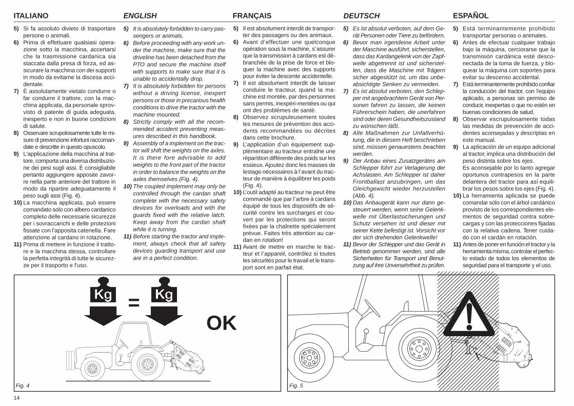
9) L'applicazione della macchina al trat-tore, comporta una diversa distribuzio-ne dei pesi sugli assi. È consigliabilepertanto aggiungere apposite zavor-re nella parte anteriore del trattore inmodo da ripartire adeguatamente ilpeso sugli assi (Fig. 4).
10) La macchina applicata, può esserecomandato solo con albero cardanicocompleto delle necessarie sicurezzeper i sovraccarichi e delle protezionifissate con l'apposita catenella. Fareattenzione al cardano in rotazione.
11) Prima di mettere in funzione il tratto-re e la macchina stessa, controllarela perfetta integrità di tutte le sicurez-ze per il trasporto e l'uso.
5) It is absolutely forbidden to carry pas-sengers or animals.
6) Before proceeding with any work un-der the machine, make sure that thedriveline has been detached from thePTO and secure the machine itselfwith supports to make sure that it isunable to accidentally drop.
7) It is absolutely forbidden for personswithout a driving license, inexpertpersons or those in precarious healthconditions to drive the tractor with themachine mounted.
8) Strictly comply with all the recom-mended accident preventing meas-ures described in this handbook.
9) Assembly of a implement on the trac-tor will shift the weights on the axles.It is there fore advisable to addweights to the front part of the tractorin order to balance the weights on theaxles themselves (Fig. 4).
10) The coupled implement may only becontrolled through the cardan shaftcomplete with the necessary safetydevices for overloads and with theguards fixed with the relative latch.Keep away from the cardan shaftwhile it is turning.
11) Before starting the tractor and imple-ment, always check that all safetydevices guarding transport and useare in a perfect condition.
5) Il est absolument interdit de transpor-ter des passagers ou des animaux.
6) Avant d’effectuer une quelconqueopération sous la machine, s’assurerque la transmission à cardans est dé-branchée de la prise de force et blo-quer la machine avec des supportspour éviter la descente accidentelle.
7) Il est absolument interdit de laisserconduire le tracteur, quand la ma-chine est montée, par des personnessans permis, inexpéri-mentées ou quiont des problèmes de santé.
8) Observez scrupuleusement toutesles mesures de prévention des acci-dents recommandées ou décritesdans cette brochure.
9) L’application d’un équipement sup-plémentaire au tracteur entraîne unerépartition différente des poids sur lesessieux. Ajoutez donc les masses delestage nécessaires à l’avant du trac-teur de manière à équilibrer les poids(Fig. 4).
10) L’outil adapté au tracteur ne peut êtrecommandé que par l’arbre à cardanséquipé de tous les dispositifs de sé-curité contre les surcharges et cou-vert par les protections qui serontfixées par la chaînette spécialementprévue. Faites très attention au car-dan en rotation!
11) Avant de mettre en marche le trac-teur et l’appareil, contrôlez si toutesles sécurités pour le travail et le trans-port sont en parfait état.
5) Es ist absolut verboten, auf dem Ge-rät Personen oder Tiere zu befördern.
6) Bevor man irgendeine Arbeit unterder Maschine ausführt, sicherstellen,dass das Kardangelenk von der Zapf-welle abgetrennt ist und sicherstel-len, dass die Maschine mit Trägernsicher abgestützt ist, um das unbe-absichtigte Senken zu vermeiden.
7) Es ist absolut verboten, den Schlep-per mit angebrachtem Gerät von Per-sonen fahren zu lassen, die keinenFührerschein haben, die unerfahrensind oder deren Gesundheitszustandzu wünschen läßt.
8) Alle Maßnahmen zur Unfallverhü-tung, die in diesem Heft beschriebensind, müssen genauestens beachtetwerden.
9) Der Anbau eines Zusatzgerätes amSchlepper führt zur Verlagerung derAchslasten. Am Schlepper ist daherFrontballast anzubringen, um dasGleichgewicht wieder herzustellen(Abb. 4).
10) Das Anbaugerät kann nur dann ge-steuert werden, wenn seine Gelenk-welle mit Überlastsicherungen undSchutz versehen ist und dieser mitseiner Kette befestigt ist. Vorsicht vorder sich drehenden Gelenkwelle!
11) Bevor der Schlepper und das Gerät inBetrieb genommen werden, sind alleSicherheiten für Transport und Benut-zung auf ihre Unversehrtheit zu prüfen.
5) Está terminantemente prohibidotransportar personas o animales.
6) Antes de efectuar cualquier trabajobajo la máquina, cerciorarse que latransmisión cardánica esté desco-nectada de la toma de fuerza, y blo-quear la máquina con soportes paraevitar su descenso accidental.
7) Está terminantemente prohibido confiarla conducción del tractor, con l'equipoaplicado, a personas sin permiso deconducir, inexpertas o que no estén enbuenas condiciones de salud.
8) Observar escrupulosamente todaslas medidas de prevención de acci-dentes aconsejadas y descriptas eneste manual.
9) La aplicación de un equipo adicionalal tractor, implica una distribución delpeso distinta sobre los ejes.Es aconsejable por lo tanto agregaroportunos contrapesos en la partedelantera del tractor para así equili-brar los pesos sobre los ejes (Fig. 4).
10) La herramienta aplicada se puedecomandar sólo con el árbol cardánicoprovisto de los correspondientes ele-mentos de seguridad contra sobre-cargas y con las protecciones fijadascon la relativa cadena. Tener cuida-do con el cardán en rotación.
11) Antes de poner en función el tractor y laherramienta misma, controlar el perfec-to estado de todos los elementos deseguridad para el transporte y el uso.
Fig. 5Fig. 4
=OK

15
ITALIANO ENGLISH FRANÇAIS ESPAÑOLDEUTSCH
12) Le etichette con le istruzioni, appli-cate sulla macchina, danno gli oppor-tuni consigli in forma essenziale perevitare gli infortuni.
13) Per la circolazione su strada, è ne-cessario attenersi alle normative delcodice stradale in vigore nel relativoPaese.
14) Il trasporto su strada avviene sotto latotale responsabilità dell'utente, cheè tenuto a verificare l'adeguatezzaalle norme del codice della strada invigore nel Paese di utilizzo.Rispettare il peso massimo previstosull'asse del trattore, il peso totalemobile, la regolamentazione sul tra-sporto e il codice stradale.
15) Prima di iniziare il lavoro, familiariz-zare con i dispositivi di comando e leloro funzioni.
16) Usare un abbigliamento idoneo. Evi-tare assolutamente abiti svolazzantio con lembi che in qualche modopotrebbero impigliarsi in parti rotantie in organi in movimento.
17) Agganciare la macchina, come pre-visto, su di un trattore di adeguatapotenza e configurazione mediantel'apposito dispositivo (sollevatore),conforme alle norme.
18) Prestare la massima attenzione nel-la fase di aggancio e sgancio dellamacchina.
19) La macchina ed i suoi eventuali ac-cessori per il trasporto su strada de-vono essere muniti di segnalazioni eprotezioni adeguate.
20) Con trattore in moto, non lasciare maiil posto di guida.
21) È molto importante tenere presenteche la tenuta di strada e la capacitàdi direzione e frenatura, possono es-sere influenzati, anche in modo no-tevole, dalla presenza della macchi-na portata o trainata.
22) In curva, fare attenzione alla forzacentrifuga esercitata in posizione di-versa, del centro di gravità, con esenza macchina portata.
23) Prima di inserire la presa di forza,accertarsi del numero di giriprestabilito. Non scambiare il regimedi 540 g/1' con i 1000 g/1'.
12) The instruction labels affixed to themachine give useful advice on howto prevent accidents.
13) Always comply with the highway codein force in your country when travel-ling on public roads.
14) Transport on roads takes place un-der the total responsibility of the user,who is obliged to verify the adequacyof the machine to the rules of the roadtraffic code in force in that country.Comply with the maximum permissi-ble weight on the axle of the tractor,the total adjustable weight, transportregulations and the highway code.
15) Always become familiar with the con-trols and their operation before start-ing work.
16) Always wear suitable clothing. Neverever wear loose garments or thosewith edges that could in some waybecome caught up in rotating partsor moving mechanisms.
17) As indicated, couple the implementto a tractor of adequate power andconfiguration, using a device (lift)conforming to the prescriptions.
18) Take the utmost care during the im-plement coupling and release phases.
19) Any accessories for transport mustbe equipped with adequate signalsand guards.
20) Never ever leave the driving seatwhilst the tractor is moving.
21) It is very important to remember thatthe road holding, steering and brak-ing capacity may be even notablyinfluenced by the presence of a towedor mounted implement.
22) Always take care of the centrifugalforce exercised by the furthered po-sition of the center of gravity, whenturning corners with the implementmounted.
23) Before engaging the pto, check thatthe rpm rate is that prescribed. Neverexchange the 540 rpm rate for 1000rpm.
12) Les étiquettes avec les instructions,appliquées sur la machine, vous don-nent les conseils utiles pour éviter lesaccidents.
13) Lors de la circulation sur route, res-pectez le code de la route en vigueurdans votre Pays.
14) Le transport sur route est effectuésous l’entière responsabilité de l’uti-lisateur qui est tenu à contrôler qu’ilsoit conforme aux normes du codede la route en vigueur dans le Paysd’utilisation. Respectez le poids maxi-mum autorisé sur l’essieu par le trac-teur, le poids total roulant, la régle-mentation sur le transport et le codede la route.
15) Avant de commencer le travail, ap-prenez à utiliser les dispositifs decommande.
16) Mettez toujours des vêtements ap-propriés.Evitez les habits amples qui pour-raient s’encastrer dans les organesen mouvement.
17) Attelez l’appareil à un tracteur d’unepuissance appropriée au moyen d’undispositif (relevage) conforme auxnormes.
18) Prêtez une attention particulière auxphases d’attelage et décrochage del’appareil.
19) Les accessoires prévus pour le trans-port doivent être équipés de disposi-tifs de signalisation et de protectionsappropriées.
20) Ne quittez jamais le poste de con-duite quand le moteur est en marche.
21) N’oubliez jamais que la tenue deroute et la capacité de direction et defreinage peuvent être modifiées con-sidérablement par les outils traînésou portés.
22) Dans les virages faites attention à laforce centrifuge exercée par la posi-tion différente du centre de gravité,avec ou sans outil porté.
23) Avant d’enclencher la prise de force,assurez-vous du nombre de tourspréconisé.Il ne faut pas changer le régime de540 tr/mn avec celui de 1.000 tr/mn.
12) Die Etiketten mit Hinweisen, die aufdem Gerät aufgeklebt sind, geben inknapper Form Anweisungen, umUnfälle zu vermeiden.
13) Bei der Teilnahme am Straßenver-kehr sind die Bestimmungen der Stra-ßenverkehrsordnung zu beachten,die in dem jeweiligen Land gelten.
14) Der Transport auf öffentlichen Stra-ßen liegt einzig und allein unter derVerantwortung des Konsumenten,der für die Befolgung der aufgrundder landesgültigen Straßenverkehrs-ordnung vorgeschriebenen Angabenzu sorgen hat.Das für die Achse vorgeseheneHöchstgewicht, das bewegliche Ge-samtgewicht, die Transport-bestimmungen und die Straßen-verkehrsordnung beachten.
15) Bevor man mit der Arbeit beginnt,sollte man sich mit den Stellteilen undihrer Funktion vertraut machen.
16) Geeignete Arbeitskleidung verwen-den.Flatternde Kleidungsstücke ab-solut vermeiden, weil diese sich inden in Rotation befindlichen Teilenverfangen könnten.
17) Das Gerät wie vorgesehen an einemSchlepper geeigneter Zugkraft undKonfiguration ankuppeln, und zwarmit einer Vorrichtung (Kraftheber), dieden Normen entspricht.
18) Bei Ein- und Auskuppeln des Gerä-tes ist immer größte Aufmerksamkeitgeboten.
19) Für den Transport müssen etwaigeZubehörteile mit Kennzeichnung ver-sehen und angemessen geschütztwerden.
20) Wenn der Schlepper in Betrieb ist, nieden Fahrerplatz verlassen.
21) Es ist sehr wichtig zu berücksichti-gen, daß die Bodenhaftung und dasLenk- und Bremsvermögen stark da-von beeinflußt werden, ob ein Anbau-gerät vorhanden ist oder nicht.
22) In Kurven auf die erhöhte Fliehkraftachten, die durch die weit vomSchwerpunkt entfernte Position desAnbaugerätes bedingt ist.
23) Vor dem Einschalten der Zapfwellesicherstellen, daß die Solldrehzahlstimmt. Die Drehzahl 540 U/min nichtmit der Drehzahl 1000 U/min ver-wechseln.
12) Las etiquetas con las instrucciones,aplicadas en la máquina, dan las opor-tunas sugerencias en forma esencialpara el tranporte y el empleo.
13) Para circular en carreteras es nece-sario respetar las normas del códigovial en vigor en el país de empleo.
14) El transporte sobre la vía pública seefectúa bajo la total responsabilidaddel usuario, quien tiene que verificarla adecuación a las normas de circu-lación en vigor en el país de empleode la máquina.Respetar el peso máximo previstosobre el eje del tractor, el peso totalmóvil, la reglamentación relativa altransporte y el código vial.
15) Antes de iniciar el trabajo, familiari-zarse con los dispositivos de mandoy las relativas funciones.
16) Usar vestidos adaptos. Evitar siem-pre las prendas amplias y convolados, que podrían engancharseen partes rotantes y en órganos enmovimiento.
17) Enganchar la máquina, como previs-to, en un tractor con potencia idóneay configuración adecuada, medianteel específico dispositivo (elevador)conforme con las normas.
18) Poner mucha atención en la fase deenganche y desenganche de la má-quina.
19) Los eventuales accesorios para eltransporte deben poseer señalizacio-nes y protecciones adecuadas.
20) Con tractor en movimiento, no aban-donar nunca el lugar de conducción.
21) Es muy importante recordar que laadherencia en carretera y la capaci-dad de dirección y frenado, puedenvariar significativamente, por la pre-sencia de un equipo transportado oremolcado.
22) En curva, prestar atención a la fuer-za centrífuga ejercitada en posicióndiversa, del centro de gravedad, cony sin equipo transportado.
23) Antes de inserir la toma de fuerza,controlar el número de revolucionesprestablecido. No confundirse entreel régimen de 540 rpm y el de 1000rpm.

ITALIANO ENGLISH FRANÇAIS ESPAÑOLDEUTSCH
16
24) È assolutamente vietato stazionarenell'area d'azione della macchina,dove vi sono organi in movimento.
25) Prima di abbandonare il trattore, ab-bassare la macchina agganciata algruppo sollevatore, arrestare il mo-tore, inserire il freno di stazionamen-to e togliere la chiave di accensionedal quadro comandi.
26) È assolutamente vietato interporsi trail trattore e la macchina (Fig. 5) conmotore acceso e cardano inseritononché senza aver azionato il frenodi stazionamento ed aver inserito,sotto le ruote, un ceppo o un sassodi bloccaggio.Mantenersi ad una distanza di sicu-rezza dalla macchina in lavoro, perpossibili lanci di corpi contundenti.
27) Prima di agganciare o sganciare lamacchina dall'attacco tre punti, met-tere in posizione di blocco la leva dicomando sollevatore.
28) La categoria dei perni di attacco del-la macchina deve corrispondere aquella dell'attacco del sollevatore.
29) Fare attenzione quando si lavoranella zona dei bracci del sollevamen-to, è un'area molto pericolosa.
30) È assolutamente vietato interporsi frail trattore e l'attacco della macchinaper manovrare il comando dall'ester-no per il sollevamento (Fig. 5).
31) In fase di trasporto, fissare con le re-lative catene e tenditori i bracci late-rali di sollevamento.
32) In fase di trasporto su strada, con lamacchina sollevata, mettere in posizio-ne di blocco la leva di comando delsollevatore idraulico del trattore.In fase di sollevamento dal terreno, igiunti dell'albero cardanico vengonopiegati a più di 40° (P.d.F. ferma), stac-care l'albero dalla P.d.F. della trattrice.
33) Utilizzare esclusivamente l'alberocardanico previsto dal Costruttore.
34) Controllare spesso e con periodicitàle protezioni dell'albero cardanico,deve essere sempre in ottimo statoe saldamente fissato.
35) Fare molta attenzione alla protezio-ne dell'albero cardanico, sia in posi-zione di trasporto che di lavoro.
24) It is absolutely forbidden to standwithin the operative range of the ma-chine where there are moving parts.
25) Before leaving the tractor, lower theimplement coupled to the lift unit, stopthe engine, engage the hand brakeand remove the ignition key from thecontrol panel.
26) It is absolutely forbidden to standbetween the tractor and the imple-ment (Fig. 5) when the engine is run-ning and the cardan shaft is engagedwithout having first engaged thehand brake and placed a block orstone under the wheels to preventthem from moving. Keep a safe dis-tance from the shredder at work toavoid being hit by possible flyingstones, etc.
27) Always set the lift control lever to thelocked position before coupling orreleasing the implement from thethree-point coupling.
28) The category of the implement cou-pling pins must correspond to that ofthe lift coupling.
29) Take care when working near the liftlinks.This is a very dangerous zone.
30) It is absolutely forbidden to standbetween the tractor and the imple-ment when manoeuvering the lift con-trol from the outside (Fig. 5).
31) Fix the side lift links with the relativechains and idlers during the transportphase.
32) Set the control lever of the hydrauliclift to the locked position during roadtransport with the implement raised.When hoisting from the ground , thejoints of the cardan shaft are bent tomore than 40° (power takeoff turnedoff). Detach the shaft from the powertakeoff of the tractor.
33) Only use the cardan shaft recom-mended by the Manufacturer.
34) Frequently and periodically check thecardan shaft guard.It must always be in an excellent con-dition and well-welded.
35) Take great care of the the cardanshaft guard, both in the transport andwork positions.
24) Il est absolument interdit de station-ner dans le rayon d’action de la ma-chine et notamment près des orga-nes en mouvement.
25) Avant de quitter le tracteur, abaissezla machine attelée au relevage, arrê-tez le moteur, bloquez le frein de sta-tionnement et retirez la clé d’allumage.
26) Il est absolument interdit de se met-tre entre le tracteur et l’appareil (Fig.5) quand le moteur est en marche etle cardan enclenché, sans avoir tiréle frein de stationnement et bloquéles roues avec une cale ou un caillou.Se tenir à une distance de sécuritédu broyeur en fonctionnement, àcause du lancement possible d’ob-jets contondants.
27) Avant de fixer ou décrocher l’appa-reil sur le troisième point d’attelage,mettez le levier de commande durelevage en position de blocage.
28) La catégorie des pivots d’attelage doitcorrespondre à celle de l’attelage durelevage.
29) Faites attention quand vous travaillezprès des bras relevage: c’est trèsdangereux.
30) Il est absolument interdit de se met-tre entre le tracteur et l’attelage pourmanoeuvrer la commande derelevage de l’extérieur (Fig. 5).
31) Lors du transport, fixez les barres derelevage par les chaînes et les ten-deurs.
32) Lors des déplacements sur route, lamachine étant soulevée, mettez lelevier de commande du relevage hy-draulique en position de blocage.En phase de soulèvement du sol, lesjoints de l’arbre à cardan sont pliés àplus de 40° (Prise de force arrêtée),détacher l’arbre de la prise de forcedu tracteur.
33) Utilisez exclusivement l’arbre à car-dans prévu par le Constructeur.
34) Contrôlez souvent et régulièrementla protection de l’arbre à cardans; elledoit être toujours en parfait état.
35) Vérifiez attentivement la protection del’arbre à cardans, aussi bien en posi-tion de transport que de travail.
24) Es ist absolut verboten, sich in derReichweite des Gerätes aufzuhalten,wo sich bewegliche Teile befinden.
25) Bevor man vom Schlepper steigt, dasam Kraftheber angekuppelte Gerätabsenken, den Motor abstellen, dieFeststellbremse ziehen und denZündschlüssel abziehen.
26) Es ist absolut verboten, bei laufen-dem Motor und eingeschalteter Ge-lenk-welle zwischen den Schlepperund das Gerät zu treten (Abb. 5).Dazu muß die Feststellbremse gezo-gen werden und unter die Räder einBremskeil oder ein großer Steingeleegt worden sein. Achten Sie beider Arbeit mit der Häckselmaschineauf den nötigen Sicherheitsabstandaufgrund der Auswurfgefahr stump-fer Gegenstände.
27) Bevor das Gerät am oberenKupplungspunkt ein oder ausge-kup-pelt wird, ist der Schalthebel desKrafthebers zu blockieren.
28) Die Kategorie der Anschlußbolzendes Gerätes muß zum Anschluß desKrafthebers passen.
29) Vorsicht beim Arbeiten im Bereich derHeberarme. Dieser Bereich ist eineGefahrenzone.
30) Es ist absolut verboten, zwischen denSchlepper und den Anschluß zu tre-ten, um die Aushebung von außenzu betätigen (Abb. 5).
31) Beim Transport müssen die seitlichenLenker mit den Stabilisierungskettenund Spannvorrichtungen befestigtwerden.
32) Beim Straßentransport mit ausge-hobenem Anbaugerät ist der Schalt-hebel des Krafthebers in die blockier-te Stellung zu setzen. Bei Anhebender Maschine werden die Kupplungs-stücke der Kardanwelle um mehr als40° abgebogen (Kraftübertragungstillstehend); die Kardanwelle von derKraftübertragung des Traktors ab-schließen.
33) Nur die vom Hersteller vorgeseheneGelenkwelle verwenden.
34) Den Gelenkwellenschutz in regel-mä-ßigen Abständen prüfen. Er muß im-mer einen ausgezeichneten Zustandaufweisen und fest verankert sein.
35) Stets auf den Gelenkwellenschutzachten, sowohl in der Arbeits- alsauch der Transportposition.
24) Está terminantemente prohibido per-manecer en el área de acción de lamáquina.
25) Antes de abandonar el tractor, bajar elequipo enganchado al grupo elevador,detener el motor, inserir el freno deestacionamiento y quitar la llave deencendido del tablero de mandos.
26) Está terminantemente prohibido co-locarse entre el tractor y el equipo(Fig. 5) con motor encendido ycardán inserido, o sin haber accio-nado el freno de estacionamiento yde colocar, debajo de las ruedas, unapiedra u otro elemento de bloqueo.Manténgase a una distancia de se-guridad del triturador durante el tra-bajo, porque puede proyectar objetos.
27) Antes de enganchar o desengancharel equipo en el tercer punto, poneren posición de bloqueo la palanca demando elevador.
28) La categoría de los pernos de engan-che del equipo debe correspondercon la del enganche del elevador.
29) Prestar atención cuando se trabajaen la zona de los brazos de eleva-ción, es un área muy peligrosa.
30) Está absolutamente prohibido colocar-se entre el tractor y el enganche paramaniobrar el mando desde el externoen la fase de elevación (Fig. 5).
31) En fase de transporte, fijar con lasrelativas cadenas y tensores los bra-zos laterales de elevación.
32) En fase de transporte en carretera,con equipo alzado, poner en posiciónde bloqueo la palanca de mando delelevador hidráulico.Durante le levantamiento del terre-no, las juntas del árbol cardán se plie-gan a más de 40° (toma de fuerzaparada), desconecte el árbol de latoma de fuerza del tractor.
33) Utilizar exclusivamente el árbolcardánico previstopor el Fabricante.
34) Controlar frecuentemente en modo pe-riódico la protección del árbol cardánico,debe encontrarse siempre en perfectoestado y fijado en modo seguro.
35) Prestar mucha atención a la protec-ción del árbol cardánico tanto en po-sición de transporte como también enposición de trabajo.
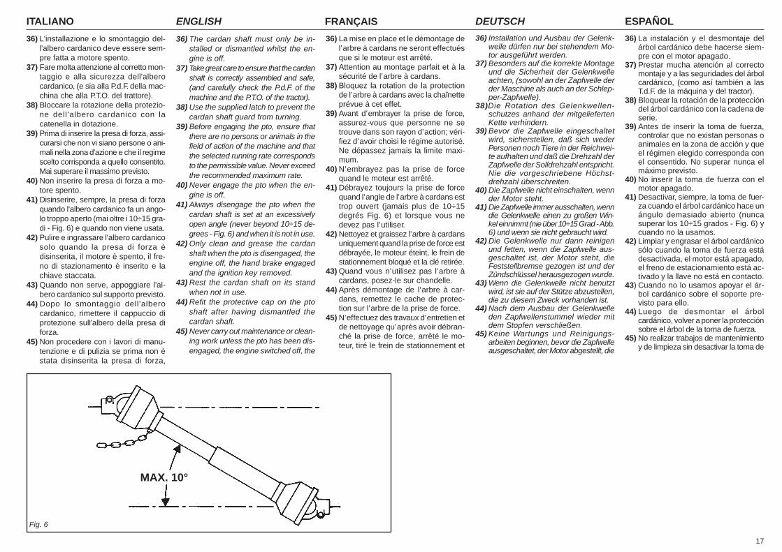
17
ITALIANO ENGLISH FRANÇAIS ESPAÑOLDEUTSCH
36) L'installazione e lo smontaggio del-l'albero cardanico deve essere sem-pre fatta a motore spento.
37) Fare molta attenzione al corretto mon-taggio e alla sicurezza dell'alberocardanico, (e sia alla P.d.F. della mac-china che alla P.T.O. del trattore).
38) Bloccare la rotazione della protezio-ne dell'albero cardanico con lacatenella in dotazione.
39) Prima di inserire la presa di forza, assi-curarsi che non vi siano persone o ani-mali nella zona d'azione e che il regimescelto corrisponda a quello consentito.Mai superare il massimo previsto.
40) Non inserire la presa di forza a mo-tore spento.
41) Disinserire, sempre, la presa di forzaquando l'albero cardanico fa un ango-lo troppo aperto (mai oltre i 10÷15 gra-di - Fig. 6) e quando non viene usata.
42) Pulire e ingrassare l'albero cardanicosolo quando la presa di forza èdisinserita, il motore è spento, il fre-no di stazionamento è inserito e lachiave staccata.
43) Quando non serve, appoggiare l'al-bero cardanico sul supporto previsto.
44) Dopo lo smontaggio dell'alberocardanico, rimettere il cappuccio diprotezione sull'albero della presa diforza.
45) Non procedere con i lavori di manu-tenzione e di pulizia se prima non èstata disinserita la presa di forza,
36) The cardan shaft must only be in-stalled or dismantled whilst the en-gine is off.
37) Take great care to ensure that the cardanshaft is correctly assembled and safe,(and carefully check the P.d.F. of themachine and the P.T.O. of the tractor).
38) Use the supplied latch to prevent thecardan shaft guard from turning.
39) Before engaging the pto, ensure thatthere are no persons or animals in thefield of action of the machine and thatthe selected running rate correspondsto the permissible value. Never exceedthe recommended maximum rate.
40) Never engage the pto when the en-gine is off.
41) Always disengage the pto when thecardan shaft is set at an excessivelyopen angle (never beyond 10÷15 de-grees - Fig. 6) and when it is not in use.
42) Only clean and grease the cardanshaft when the pto is disengaged, theengine off, the hand brake engagedand the ignition key removed.
43) Rest the cardan shaft on its standwhen not in use.
44) Refit the protective cap on the ptoshaft after having dismantled thecardan shaft.
45) Never carry out maintenance or clean-ing work unless the pto has been dis-engaged, the engine switched off, the
36) La mise en place et le démontage del’arbre à cardans ne seront effectuésque si le moteur est arrêté.
37) Attention au montage parfait et à lasécurité de l’arbre à cardans.
38) Bloquez la rotation de la protectionde l’arbre à cardans avec la chaînetteprévue à cet effet.
39) Avant d’embrayer la prise de force,assurez-vous que personne ne setrouve dans son rayon d’action; véri-fiez d’avoir choisi le régime autorisé.Ne dépassez jamais la limite maxi-mum.
40) N’embrayez pas la prise de forcequand le moteur est arrêté.
41) Débrayez toujours la prise de forcequand l’angle de l’arbre à cardans esttrop ouvert (jamais plus de 10÷15degrés Fig. 6) et lorsque vous nedevez pas l’utiliser.
42) Nettoyez et graissez l’arbre à cardansuniquement quand la prise de force estdébrayée, le moteur éteint, le frein destationnement bloqué et la clé retirée.
43) Quand vous n’utilisez pas l’arbre àcardans, posez-le sur chandelle.
44) Après démontage de l’arbre à car-dans, remettez le cache de protec-tion sur l’arbre de la prise de force.
45) N’effectuez des travaux d’entretien etde nettoyage qu’après avoir débran-ché la prise de force, arrêté le mo-teur, tiré le frein de stationnement et
36) Installation und Ausbau der Gelenk-welle dürfen nur bei stehendem Mo-tor ausgeführt werden.
37) Besonders auf die korrekte Montageund die Sicherheit der Gelenkwelleachten, (sowohl an der Zapfwelle derder Maschine als auch an der Schlep-per-Zapfwelle).
38)Die Rotation des Gelenkwellen-schutzes anhand der mitgeliefertenKette verhindern.
39) Bevor die Zapfwelle eingeschaltetwird, sicherstellen, daß sich wederPersonen noch Tiere in der Reichwei-te aufhalten und daß die Drehzahl derZapfwelle der Solldrehzahl entspricht.Nie die vorgeschriebene Höchst-drehzahl überschreiten.
40) Die Zapfwelle nicht einschalten, wennder Motor steht.
41) Die Zapfwelle immer ausschalten, wenndie Gelenkwelle einen zu großen Win-kel einnimmt (nie über 10÷15 Grad - Abb.6) und wenn sie nicht gebraucht wird.
42) Die Gelenkwelle nur dann reinigenund fetten, wenn die Zapfwelle aus-geschaltet ist, der Motor steht, dieFeststellbremse gezogen ist und derZündschlüssel herausgezogen wurde.
43) Wenn die Gelenkwelle nicht benutztwird, ist sie auf der Stütze abzustellen,die zu diesem Zweck vorhanden ist.
44) Nach dem Ausbau der Gelenkwelleden Zapfwellenstummel wieder mitdem Stopfen verschließen.
45) Keine Wartungs und Reinigungs-arbeiten beginnen, bevor die Zapfwelleausgeschaltet, der Motor abgestellt, die
36) La instalación y el desmontaje delárbol cardánico debe hacerse siem-pre con el motor apagado.
37) Prestar mucha atención al correctomontaje y a las seguridades del árbolcardánico, (como así también a lasT.d.F. de la máquina y del tractor).
38) Bloquear la rotación de la proteccióndel árbol cardánico con la cadena deserie.
39) Antes de inserir la toma de fuerza,controlar que no existan personas oanimales en la zona de acción y queel régimen elegido corresponda conel consentido. No superar nunca elmáximo previsto.
40) No inserir la toma de fuerza con elmotor apagado.
41) Desactivar, siempre, la toma de fuer-za cuando el árbol cardánico hace unángulo demasiado abierto (nuncasuperar los 10÷15 grados - Fig. 6) ycuando no la usamos.
42) Limpiar y engrasar el árbol cardánicosólo cuando la toma de fuerza estádesactivada, el motor está apagado,el freno de estacionamiento está ac-tivado y la llave no está en contacto.
43) Cuando no lo usamos apoyar el ár-bol cardánico sobre el soporte pre-visto para ello.
44) Luego de desmontar el árbolcardánico, volver a poner la protecciónsobre el árbol de la toma de fuerza.
45) No realizar trabajos de mantenimientoy de limpieza sin desactivar la toma de
Fig. 6
MAX. 10°
ITALIANO ENGLISH FRANÇAIS ESPAÑOLDEUTSCH
18
spento il motore, inserito il freno di sta-zionamento e bloccato il trattore conun ceppo o un sasso sotto le ruote.Controllare l'integrità delle bandelledi protezione e della struttura.
46) Periodicamente verificare il serraggioe la tenuta delle viti e dadi, eventual-mente riserrarli.
47) Nei lavori di manutenzione e di sosti-tuzione dei coltelli con la macchinasollevato, mettere per precauzioneadeguati sostegni sotto l'attrezzatura.
48) Prima di lavorare sugli utensili da ta-glio; staccare la presa di forza, spe-gnere il trattore, inserire il freno distazionamento ed assicurarsi che gliutensili siano completamente fermi.
49) Rispettare la conformità degli olii con-sigliati.
50) Le parti di ricambio devono corrispon-dere alle esigenze definite dalcostruttore. Usare solo ricambi originali.
51) Le decalcomanie relative alla sicu-rezza devono essere sempre benevidenti; vanno tenute pulite e vannosostituite se diventano poco leggibili(eventualmente possono essere ri-chieste al concessionario).
52) Il libretto delle istruzioni per l'uso,deve essere conservato per tutta ladurata della macchina.
ATTENZIONENel caso si utilizzi una trattice priva dicabina insonorizzata e pressurizzata,è necessario che l'operatore utilizzisistemi individuali di protezione:- Cuffia protettiva per il rumore, se si ec-
cedono i livelli di esposizione di norma.- Maschera antipolvere, se a causa del
tipo di prodotto lavorato o del terrenomolto polveroso, o uso di macchinaaperta, si sollevi una notevole quanti-tà di polvere.
hand brake engaged and the tractorlocked in position by a block or stoneunder the wheels.Check the state and condition of theprotection bars.
46) Periodically check that all nuts andbolts are fully tightened. Re-tightenthem if necessary.
47) Always place adequate supports un-der the implement when servicing themachine or replacing the hoe bladeswith the implement raised.
48) Before working on the cutting tools,disengage the pto, switch off the trac-tor engine, engage the hand brakeand check that the blades are com-pletely at a standstill.
49) Only use the recommended oils.50) The spare parts must correspond to
the requirements established by themanufacturer. Only use genuinespare parts.
51) The safety transfers must always beperfectly visible. They must be keptclean and should be replaced if theybecome illegible. Replacements areavailable on request from your localdealer.
52) The instruction manual must be keptfor as long as the machine lasts.
ATTENTIONIn the event a tractor is used that hasno pressurized, soundproof cabin theoperator must use individual methodsof protection.- Protective headphones for noise in
case the standard levels of exposureare exceeded.
- Anti-dust mask, if a considerable quan-tity of dust is raised caused by the typeof product cut, by very dusty earth, orby the use of an open machine.
bloqué le tracteur avec une cale ouun caillou sous les roues. Contrôlerl’intégrité des bandes de protectionet de la structure.
46) Vérifiez périodiquement le serrage etla tenue des vis et des écrous. Aubesoin resserrez-les.
47) Quand vous devez remplacer lescouteaux ou effectuer des interven-tions sur l’outil soulevé, n’oubliez pasde mettre des supports appropriéssous l’appareil.
48) Avant d’intervenir sur les outils decoupe, débrayez la prise de force,arrêtez le moteur, bloquez le frein destationnement et assurez-vous queles outils sont arrêtés.
49) Utilisez exclusivement les huiles pré-conisées.
50) Les pièces détachées doivent corres-pondre aux exigences définies par leconstructeur. Utilisez unique-mentdes pièces d’origine.
51) Les décalcomanies relatives à la sé-curité doivent être toujours visables.Il faut les garder bien propres et lesremplacer dès qu’elles sont peu lisi-bles (vous pouvez éventuellement lesdemander au concessionnaire).
52) La notice d’instructions doit être con-servée pour toute la durée de la ma-chine.
ATTENTIONS’il se sert d’un tracteur sans cabineinsonorisée et pressurisée, l’opéra-teur doit utiliser des systèmes indivi-duels de protection tels que:- Casque de protection contre le bruit si le
niveau dépasse celui prévu par la norme.- Masque anti-poussière si on soulève
une grande quantité de poussière àcause du type de produit travaillé, duterrain très poussiéreux ou si on uti-lise la machine ouverte.
Feststellbremse gezogen und dieSchlepperräder durch Unterlegen einesBremskeils oder eines großen Steinsblockiert worden sind. Den einwandfrei-en Zustand der Schutzblenden in regel-mäßigen Abständen kontrollieren.
46) Alle Schrauben und Muttern regelmä-ßig auf festen Sitz prüfen und ggf.nachziehen.
47) Bei Wartungsarbeiten und beim Erset-zen der Hackmesser bei aufgebocktemGerät ist dieses zur Vorsicht mit geeig-neten Vorrichtungen abzustützen.
48) Bevor man an den Schneide-werk-zeugen arbeitet, die Zapfwelle aus-schalten, den Motor abstellen, die Fest-stellbremse ziehen und sicherstellen,daß die Werkzeuge ganz stillstehen.
49) Darauf achten, die empfohlenenSchmierstoffe zu benutzen.
50) Die Ersatzteile müssen den Ansprü-chen gerecht werden, die der Herstel-ler angibt. Nur Original-Ersatzteileverwenden.
51) Die Sicherheitsaufkleber müssen immergut sichtbar sein. Sie sind daher sau-ber zu halten und zu ersetzen, wenn sieunleserlich werden (Können ggf. beimVertragshändler angefordert werden).
52) Die Betriebsanleitung der Maschineist sorgfältig aufzubewahren, solan-ge die Maschine Vorhanden ist.
ACHTUNGSollte ein Traktor ohne schall-gedämpfter Druckkabine verwendetwerden, so hat der Lenker des Traktorsmit folgenden individuellen Schutzvor-richtungen ausgestattet zu werden:- Ohrenschützer, falls die gesetzlich ge-
nehmigte Geräuschbelastung über-schritten wird.
- Staubschutzmaske, falls aufgrund deszu behandelnden Materials, bzw. auf-grund besonders staubigen Bodensbeim Betrieb der Maschine große Men-gen an Staub anfallen.
fuerza, apagar el motor, activar el frenode estacionamiento y bloquear el trac-tor con una piedra u otro elemento.Controle la integridad de las bandasde protección y estructura.
46) Periódicamente controlar el ajuste delos tornillos y tuercas, eventualmen-te apretarlos.
47) En los trabajos de mantenimiento y desustitución de las azadas con el equi-po alzado, poner por precaución ade-cuados soportes debajo de el equipo.
48) Antes de trabajar con las herramien-tas de corte: desenganchar la tomade fuerza, apagar el tractor, activarel freno de estacionamiento y con-trolar que las herramientas esténdetenidas.
49) Respetar las características de losaceite aconsejados.
50) Los repuestos deben corresponder alas exigencias definidas por el fabrican-te. Usar siempre repuestos originales.
51) Las calcomanias correspondientes ala seguridad deben siempre ser evi-dentes; hay que limpiarlas y sustituir-las si no son leibles (eventualmentepodemos solicitarlos al concesionario).
52) El manual de las instrucciones deempleo debe guardarse durante todala vida de la maquina.
ATENCIÓNEn el caso se utilice un tractor sin ca-bina insonorizada y presurizada, esnecesario che el operador utilice lossistemas individuales de protección:- Auriculares para el ruido, si se exceden
los niveles de exposición de norma.- Máscara para el polvo si a causa del
tipo de producto elaborado, del terre-no polvoroso, o de la máquina abierta,se levanta una cantidad de polvo con-siderable.
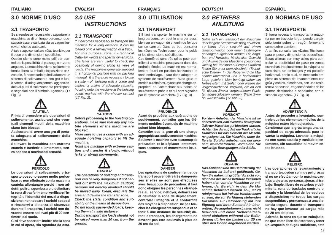
19
ITALIANO ENGLISH FRANÇAIS ESPAÑOLDEUTSCH
3.0 NORME D'USO
3.1 TRASPORTOSe si rendesse necessario trasportare lamacchina su di un lungo percorso, que-sta può essere caricata sia su vagoni fer-roviari che su autocarri.A tale scopo consultare «Dati tecnici», peril peso e le dimensioni specifiche.Queste ultime sono molto utili per con-trollare la possibilità di passaggio in zoneanguste. La macchina viene solitamentefornita libera da imballi e in posizione oriz-zontale, è necessario quindi adottare unsistema di sollevamento con gru e funi,o catene, di adeguata portata, aggancian-dolo ai punti di sollevamento predispostie segnalati con il simbolo «gancio» (17Fig. 3).
CAUTELAPrima di procedere alle operazioni disollevamento, assicurarsi che even-tuali elementi mobili della macchinasiano ben bloccati.Assicurarsi di avere una gru di porta-ta adeguata al sollevamento dellamacchina.Sollevare la macchina con estremacautela e trasferirlo lentamente, sen-za scosse o movimenti bruschi.
PERICOLOLe operazioni di sollevamento e tra-sporto possono essere molto perico-lose se non effettuate con la massimacautela: allontanare perciò i non ad-detti; pulire, sgomberare e delimitarela zona di trasferimento; verificare l’in-tegrità e l’idoneità dei mezzi a dispo-sizione; non toccare i carichi sospesie rimanervi a distanza di sicurezza;durante il trasporto, i carichi non do-vranno essere sollevati più di 20 cen-timetri dal suolo.Ci si deve accertare inoltre che la zonain cui si opera, sia sgombra da osta-
3.0 USEINSTRUCTIONS
3.1 TRANSPORTIf it becomes necessary to transport themachine for a long distance, it can beloaded onto a railway wagon or a truck.For this purpose, consult «TechnicalData» for weight and specific dimensions.The latter are very useful to check thepossibility of driving along all types ofroads. The machine is generally suppliedin a horizontal position with no packingmaterial. It is therefore necessary to usea system of hoisting with a crane andcables, or chains of adequate capacity,hooking onto the machine at the hoistingpoints marked with the «hook» symbol(17 Fig. 3).
CAUTIONBefore proceeding to the hoisting op-erations, make sure that any any mo-bile elements of the machine areblocked.Make sure to use a crane with an ad-equate hoisting capacity to lift themachine.Hoist the machine with extreme cau-tion and transfer it slowly, withoutjerks or abrupt movements.
DANGERThe operations of hoisting and trans-port can be very dangerous if not car-ried out with the maximum caution;persons not directly involved shouldbe moved away. Clean, evacuate thearea and delimit the transfer zone.Check the state, condition and suit-ability of the means at disposition.Do not touch suspended loads, keep-ing them at a safe distanceDuring transport, the loads should notbe raised more than 20 cm. from theground.
3.0 UTILISATION
3.1 TRANSPORTS’il faut transporter le machine sur unlong parcours, on peut le charger aussibien sur un wagon de chemin de fer quesur un camion. Dans ce but, consulterles «Donnes Techniques» pour le poidset les dimensions spécifiques.Ces dernières sont très utiles pour con-trôler si la machine peut passer dans desendroits étroits. Le machine est norma-lement fourni en position horizontale etsans emballage, il faut donc adopter unsystème de soulèvement avec grue etcordes ou chaînes, ayant une charge ap-propriée, en l’accrochant aux points desoulèvement prévus et qui sont signaléspar le symbole «crochet» (17 Fig. 3).
PRUDENCEAvant de procéder aux opérations desoulèvement, contrôler que les élé-ments mobiles éventuels de machinesoient bien bloqués.Contrôler que la grue ait une chargeappropriée au soulèvement de machine.Soulever le machine avec beaucoup deprécaution et le déplacer lentement,sans secousses ni mouvements brus-ques.
DANGERLes opérations de soulèvement et detransport peuvent être très dangereu-ses si elles ne sont pas effectuéesavec beaucoup de précaution: il fautdonc éloigner les personnes étrangè-res au service; nettoyer, débarrasseret délimiter la zone de déplacement;contrôler l’intégrité et la conformitédes moyens à disposition; ne pas tou-cher les chargements suspendus et setenir à une distance de sécurité; du-rant le transport, les chargements nedevront pas être soulevés à plus de20 cm du sol.
3.0 BETRIEBSANLEITUNG
3.1 TRANSPORTSollte sich ein Transport der Maschineüber längere Strecken als nötig erweisen,so kann diese sowohl auf einenTransportwagon oder einen Lastwagen-anhänger aufgeladen werden. Die Anga-ben und Hinweise hinsichtlich Gewichtund Ausmaße der Maschine (besonderswichtig bei Transport auf engen Straßen)finden Sie unter dem Abschnitt «Techni-sche Daten». In der Regel wird die Ma-schine unverpackt und in horizontalerLage geliefert. Man benötigt daher einHebesystem mit Seilen oder Ketten dervorgeschriebenen Tragkraft, die an denfür diesen Zweck vorgesehenen Punk-ten angeschlossen werden. Siehe Sym-bol «Anschluß» (17 Abb. 3).
VORSICHTVor dem Anheben der Maschine ist si-cherzustellen, daß eventuell beweglicheTeile der Maschine gut blockiert wurden.Achten Sie darauf, daß die Tragkraft desHubwerks für das Gewicht der Maschi-ne geeignet ist. Die Maschine unter äu-ßerster Sorgfalt anheben und nur lang-sam weiterbefördern. Vermeiden Sieruckartige Bewegungen oder Stöße.
GEFAHRDas Anheben und die Beförderung derMaschine ist äußerst gefährlich. Ge-hen Sie dabei mit größter Vorsicht vor;nicht mit der Arbeit betraute Personenhaben sich von der Maschine zu ent-fernen; der Bereich, in dem die Ma-schine befördert werden soll, ist zureinigen und hat frei von Hindernissenzu sein; die zur Verfügung stehendenHilfsmittel zur Beförderung auf ihreEignung und ihren Zustand hin über-prüfen; die angehobenen Lasten nichtberühren und einen Sicherheitsab-stand einhalten; während der Beför-derung dürfen die Lasten nur 20 cmüber den Boden angehoben werden.
3.0 NORMAS DE USO
3.1 TRANSPORTESi fuera necesario transportar la máqui-na por un trayecto largo, puede cargár-selo tanto sobre un vagón ferroviariocomo sobre camión.A tal fin, consulte las «Datos Técnicos»para el peso y dimensiones específicas.Éstas últimas son muy útiles para con-trolar la posibilidad de paso en zonasestrechas. Habitualmente, la máquina sesuministra sin embalajes y en posiciónhorizontal, por lo cual, es necesario em-plear un sistema de levantamiento congrúa y cables, o cadenas, con una resis-tencia adecuada, enganchándolos de lospuntos destinados e señalados con elsímbolo «gancho» (17 Fig. 3).
ADVERTENCIAAntes de proceder a levantarlo, con-trole que los elementos móviles de lamáquina estén bien sujetados.Cerciórese que la grúa tenga una ca-pacidad de carga adecuada para le-vantar la máquina. Levante la máqui-na con suma cautela y trasládelo len-tamente, sin sacudidas ni movimien-tos bruscos.
PELIGROLas operaciones de levantamiento ytransporte pueden ser muy peligrosassi no se efectúan con la máxima cau-tela: aleje a las personas ajenas al tra-bajo; limpie, libere de estorbos y deli-mite la zona de traslado; controle elestado y la idoneidad de los equiposa disposición; no toque las cargassuspendidas y permanezca a una dis-tancia segura; durante el transporteno hay que levantar las cargas másde 20 cm del piso.Además, la zona en que se trabaja tie-ne que estar libre de estorbos y tenerun «espacio de fuga» suficiente, éste
ITALIANO ENGLISH FRANÇAIS ESPAÑOLDEUTSCH
20
coli e che vi sia un sufficiente «spaziodi fuga», intendendo con questo ter-mine, una zona libera e sicura, in cuipotersi spostare rapidamente qualo-ra il carico cadesse.Il piano su cui si intende caricare la mac-china, deve essere orizzontale per evita-re possibili spostamenti del carico.
Una volta posta la macchina sull'even-tuale mezzo di trasporto, assicurarsi cherimanga bloccata nella sua posizione.Fissare la macchina al piano su cui èappoggiato mediante l’ausilio di funi adat-te alla massa di cui si intende bloccare ilmovimento (vedere «Dati tecnici» per ilpeso).Dette funi devono essere fissate saldamen-te alla macchina e ben tese verso il puntodi ancoraggio sul piano di appoggio.Una volta effettuato il trasporto, prima diliberare la macchina da tutti i vincoli, ve-rificare che lo stato e la posizione dellostesso siano tali da non costituire peri-colo.Togliere quindi le funi, e procedere alloscarico con gli stessi mezzi e modalitàprevisti per il carico.
Transito e trasporto su stradepubblicheQuando si transita su strade pubbliche ènecessario montare i triangoli posterioricatarifrangenti, le luci di segnalazionedegli ingombri, il lampeggiante e comun-que accertarsi delle leggi e regolamen-tazioni vigenti per il transito.
ATTENZIONEPrima di immettersi su strade pubbli-che con la macchina agganciata altrattore verificare la presenza e l’effi-cienza dei dispositivi sopra descrittie/o del segnale di veicolo lento e/o dicarico sporgente.Questi indicatori devono trovarsi sulretro della macchina operatrice in po-sizione ben visibile da ogni mezzo chesopraggiunga posteriormente.
It most be further ascertained that theoperational area is free of obstaclesand that there is sufficient «escapespace», meaning an area which is freeand secure into which one could moverapidly in case a load should fall.The surface on which the machine isto be loaded must be horizontal in or-der to prevent possible shifting.
Once the machine is positioned on thevehicle, make sure that it remainsblocked in its position.Fasten the machine on the platform ofthe vehicle by means of cables suitablefor the mass which must be blocked (see«Technical Data» for the weight).The cables must be firmly fastened to themachine and pulled taut to the anchor-age point on the platform.Once transport has been carried out andbefore freeing the machine from all itsfastenings, make sure that its state andposition are such as not to constitutedanger.Remove the cables and proceed to un-loading with the same means and meth-ods used for loading.
Transit and transporting on thepublic highwaysWhen driving on the public roads, fit onthe rear reflector triangles, side lights andflashing beacon and always make surethat you comply with the Highway Codeand any other applicable regulations.
ATTENTIONBefore driving on to the public roadswith the machine hitched to the trac-tor, make sure that the devices listedabove and/or the slow vehicle signaland/or the projecting load signal op-erate correctly.These indicators must be affixed to therear of the implement in a positionwhere they can be clearly seen by anyother vehicle that drives up behind.
Par ailleurs, il faut contrôler que la zoneoù l’on opère soit libre d’obstacles etqu’il y ait un «espace de fuite» suffi-sant, c’est-à-dire une zone libre et sûrepour pouvoir s’y réfugier rapidementsi le chargement devait tomber.La plate-forme sur laquelle on veutcharger le broyeur doit être horizon-tale pour éviter les déplacements pos-sibles du chargement.
Après avoir placé le machine sur le moyende transport éventuel, contrôler qu’il restebien bloqué dans cette position.Fixer le machine à la plate-forme sur la-quelle il est posé à l’aide de cordes ap-propriées à la masse dont on veut blo-quer le mouvement (pour le poids, voir«Donnes Techniques»).Ces cordes doivent être fixées solide-ment au machine et doivent être bien ten-dues vers le point d’ancrage sur le pland’appui.Après avoir effectué le transport et avantde détacher le machine, contrôler quel’état et la position de celui-ci ne repré-sentent pas un danger.Enlever ensuite les cordes et déchargerde la même façon et en utilisant les mê-mes moyens que pour le chargement.
Déplacement et circulation surles voies publiquesLors d’un déplacement sur la voie publi-que il faut monter les triangles arrièreréfléchissant, les feux de signalisationdes gabarits, le gyrophare, le clignotantet vérifier les lois et les réglementationsen vigueur pour la circulation.
ATTENTIONAvant de s’engager sur les voies pu-bliques avec la machine attelée autracteur, vérifier la présence et l’effi-cacité des dispositifs décrits ci-des-sus ou du signal de véhicule lent oude charge en saillie.Ces signalisations doivent être fixéesà l’arrière de la machine dans une po-sition bien visible par tout véhiculeprovenant par l’arrière.
Versichern Sie sich, daß der gesamteBereich, in dem die Maschine beför-dert werden soll, frei von jeder Art vonHindernissen ist und daß «Fluchtwe-ge» bestehen, die dem Betriebs-personal ein unverzügliches Verlas-sen des Bereichs ermöglichen, solltedie Last herabfallen.Die Unterlage, auf die die Maschineabgestellt werden soll, hat horizontalund vollkommen eben zu sein, um einKippen der Last zu vermeiden.
Ist die Maschine auf das Transportmittelaufgeladen, ist sicherzustellen, daß die-se gut blockiert und befestigt ist.Die Maschine mithilfe geeigneter Seile(siehe Masse der Maschine - Abschnitt«Technische Daten») mit der Unterlagedes Transportmittels verbinden, um eineBewegung der Maschine während desTransports zu vermeiden.Befestigen Sie diese Seile mit der Ma-schine und achten sie darauf, daß sie mitder geeigneten Spannung an der Unter-lage befestigt wurden.Nach Beendigung des Transports und vor-dem neuerlichen Abladen der Maschine istdarauf zu achten, daß sich diese in einerPosition befindet, in der das Loslösen derBefestigungen keine Gefahr darstellt.Anschließend die Seile lösen und dieMaschine unter den, zum Aufladen an-geführten, Voraussetzungen abladen.
Fahren auf öffentlichen StraßenWenn man auf öffentlichen Straßen fährt,müssen hinten die rückstrahlenden Drei-ecke, das Standlicht und die Blinker mon-tiert werden. Man muss auf jeden Fall dieGesetze und Bestimmungen beachten,die für den Straßenverkehr gelten.
ACHTUNGBevor man mit der am Traktor ange-bauten Maschine auf öffentliche Stra-ßen fährt, sicherstellen, dass die obenbeschriebenen Vorrichtrungen und/oder das Signal für langsam fahrendeFahrzeuge und/oder überstehendeLasten vorhanden und funktionstüch-tig sind. Diese Anzeigen müssen sichauf der Rückseite der Arbeitsmaschi-ne befinden, in einer Position, die je-des hinter dem Traktor fahrende Fahr-zeug gut sehen kann.
termino significa que tiene que haberuna zona libre y segura, a la cual po-der desplazarse rápidamente si la car-ga cayera.El plano sobre el que se descargarála máquina tiene que ser horizontalpara evitar posibles desplazamientosde la carga.
Una vez cargado la sobre el medio detransporte, controle que quede bloquea-do en su posición.Fije la máquina al plano sobre el cual estáapoyado mediante cables adecuados alpeso del cual se desea bloquear el mo-vimiento (para el peso, véase «DatosTécnicos»).Dichos cables deben estar firmemente fi-jados la máquina y bien tensos hacia elpunto de anclaje sobre el plano de apoyo.Una vez efectuado el transporte, antes deliberar la máquina de todas las ligaduras,controle que el estado y la posición delmismo no constituyan un peligro.Entonces, quite los cables; y descárgue-lo con los mismos medios y modos pre-vistos para la carga.
Tránsito y transporte en carre-teras públicasCuando se transita en carreteras públi-cas es necesario montar los triángulostraseros reflectantes, las luces de des-peje, el intermitente y respetar siemprelas leyes locales vigentes de tránsito.
ATENCIÓNAntes de entrar en una carretera pú-blica con la máquina enganchada enel tractor controlar la presencia y lafuncionalidad de los dispositivos an-tes descritos y/o de la señal de vehí-culo lento y/o de carga saliente.Estos indicadores deben estarposicionados en la parte posterior dela máquina en posición bien visiblepara los medios que se acerquen pordetrás.
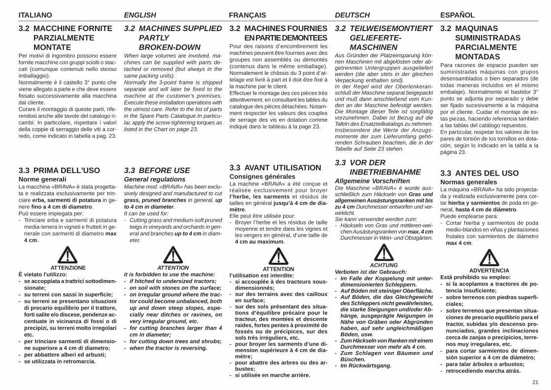
21
ITALIANO ENGLISH FRANÇAIS ESPAÑOLDEUTSCH
3.2 MACCHINE FORNITEPARZIALMENTEMONTATE
Per motivi di ingombro possono esserefornite macchine con gruppi sciolti o stac-cati (comunque contenuti nello stessoimballaggio).Normalmente è il castello 3° punto cheviene allegato a parte e che deve esserefissato successivamente alla macchinadal cliente.Curare il montaggio di queste parti, rife-rendosi anche alle tavole del catalogo ri-cambi. In particolare, rispettare i valoridella coppie di serraggio delle viti a cor-redo, come indicato in tabella a pag. 23.
3.3 PRIMA DELL'USONorme generaliLa macchina «BRAVA» è stata progetta-ta e realizzata esclusivamente per trin-ciare erba, sarmenti di potatura in ge-nere fino a 4 cm di diametro.Può essere impiegata per:- Trinciare erba e sarmenti di potatura
media-tenera in vigneti e frutteti in ge-nerale con sarmenti di diametro max4 cm.
ATTENZIONEÈ vietato l'utilizzo:- se accoppiata a trattrici sottodimen-
sionate;- su terreni con sassi in superficie;- su terreni se presentano situazioni
di precario equilibrio per il trattore,forti salite e/o discese, pendenze ac-centuate in vicinanza di fossi o diprecipizi, su terreni molto irregolarietc.
- per trinciare sarmenti di dimensio-ne superiore a 4 cm di diametro;
- per abbattere alberi ed arbusti;- se utilizzata in retromarcia.
3.2 MACHINES SUPPLIEDPARTLYBROKEN-DOWN
When large volumes are involved, ma-chines can be supplied with parts de-tached or removed (but always in thesame packing units).Normally the 3-point frame is shippedseparate and will later be fixed to themachine at the customer’s premises.Execute these installation operations withthe utmost care. Refer to the list of partsin the Spare Parts Catalogue.In particu-lar, apply the screw tightening torques aslisted in the Chart on page 23.
3.3 BEFORE USEGeneral regulationsMachine mod. «BRAVA» has been exclu-sively designed and manufactured to cutgrass, pruned branches in general, upto 4 cm in diameter.It can be used for:- Cutting grass and medium-soft pruned
twigs in vineyards and orchards in gen-eral and branches up to 4 cm in diam-eter.
ATTENTIONit is forbidden to use the machine:- if hitched to undersized tractors;- on soil with stones on the surface;- on irregular ground where the trac-
tor could become unbalanced, bothup and down steep slopes, espe-cially near ditches or ravines, onvery irregular ground, etc.
- for cutting branches larger than 4cm in diameter;
- for cutting down trees and shrubs;- when the tractor is reversing.
3.2 MACHINES FOURNIESEN PARTIE DEMONTEES
Pour des raisons d’encombrement lesmachines peuvent être fournies avec desgroupes non assemblés ou démontés(contenus dans le même emballage).Normalement le châssis du 3 point d’at-telage est livré à part et il doit être fixé àla machine par le client.Effectuer le montage des ces pièces trèsattentivement, en consultant les tables ducatalogue des pièces détachées. Notam-ment respecter les valeurs des couplesde serrage des vis en dotation commeindiqué dans le tableau à la page 23.
3.3 AVANT UTILISATIONConsignes généralesLa machine «BRAVA» a été conçue etréalisée exclusivement pour broyerl’herbe, les sarments et résidus detailles en général jusqu’à 4 cm de dia-mètre.Elle peut être utilisée pour:- Broyer l’herbe et les résidus de taille
moyenne et tendre dans les vignes etles vergers en général, d’une taille de4 cm au maximum.
ATTENTIONl’utilisation est interdite:- si accouplée à des tracteurs sous-
dimensionnés;- sur des terrains avec des cailloux
en surface;- sur des sols présentant des situa-
tions d’équilibre précaire pour letracteur, des montées et descenteraides, fortes pentes à proximité defossés ou de précipices, sur dessols très irréguliers, etc.
- pour broyer les sarments d’une di-mension supérieure à 4 cm de dia-mètre;
- pour abattre des arbres ou des ar-bustes;
- si utilisée en marche arrière.
3.2 TEILWEISEMONTIERTGELIEFERTE-MASCHINEN
Aus Gründen der Platzeinsparung kön-nen Maschinen mit abgelösten oder ab-getrennten Untergruppen ausgeliefertwerden (die aber stets in der gleichenVerpackung enthalten sind).In der Regel wird der Oberlenkeran-schluß der Maschine separat beigepacktund muß dann anschließend vom Kun-den an der Maschine befestigt werden.Die Montage dieser Teile ist sorgfältigvorzunehmen. Dabei ist Bezug auf dieTafeln des Ersatzteilkatalogs zu nehmen.Insbesondere die Werte der Anzugs-momente der zum Lieferumfang gehö-renden Schrauben beachten, die in derTabelle auf Seite 23 stehen.
3.3 VOR DERINBETRIEBNAHME
Allgemeine VorschriftenDie Maschine «BRAVA» è wurde aus-schließlich zum Häckseln von Gras undallgemeinen Ausästungsranken mit biszu 4 cm Durchmesser entworfen und ver-wirklicht.Sie kann verwendet werden zum:- Häckseln von Gras und mittleren-wei-
chen Ausästungsranken von max. 4 cmDurchmesser in Wein- und Obstgärten.
ACHTUNGVerboten ist der Gebrauch:- Im Falle der Koppelung mit unter-
dimensionierten Schleppern.- Auf Böden mit steiniger Oberfläche.- Auf Böden, die das Gleichgewicht
des Schleppers nicht gewährleisten,die starke Steigungen und/oder Ab-hänge, ausgeprägte Neigungen inNähe von Gräben oder Abgründenhaben, auf sehr ungleichmäßigenBöden, usw.
- Zum Häckseln von Ranken mit einemDurchmesser von mehr als 4 cm.
- Zum Schlagen von Bäumen undBüschen.
- Im Rückwärtsgang.
3.2 MAQUINASSUMINISTRADASPARCIALMENTEMONTADAS
Para razones de espacio pueden sersuministradas máquinas con gruposdesensamblados o bien separados (detodas maneras incluidos en el mismoembalaje). Normalmente el bastidor 3°punto se adjunta por separado y debeser fijado sucesivamente a la máquinapor el cliente. Cuidar el montaje de es-tas piezas, haciendo referencia tambiéna las tablas del catálogo repuestos.En particular, respetar los valores de lospares de torsión de los tornillos en dota-ción, según lo indicado en la tabla a lapágina 23.
3.3 ANTES DEL USONormas generalesLa máquina «BRAVA» ha sido proyecta-da y realizada exclusivamente para cor-tar hierba y sarmientos de poda en ge-neral, hasta 4 cm de diámetro.Puede emplearse para:- Cortar hierba y sarmientos de poda
medio-blandos en viñas y plantacionesfrutales con sarmientos de diámetromax 4 cm.
ADVERTENCIAEstá prohibido su empleo:- si la acoplamos a tractores de po-
tencia insuficiente;- sobre terrenos con piedras superfi-
ciales;- sobre terrenos que presentan situa-
ciones de precario equilibrio para eltractor, subidas y/o descenso pro-nunciados, grandes inclinacionescerca de zanjas o precipicios, terre-nos muy irregulares, etc.
- para cortar sarmientos de dimen-sión superior a 4 cm de diámetro;
- para talar árboles o arbustos;- retrocediendo marcha atrás.
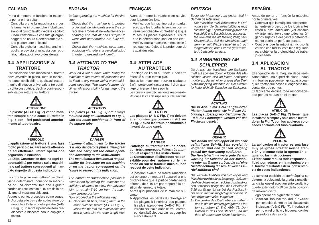
ITALIANO ENGLISH FRANÇAIS ESPAÑOLDEUTSCH
22
Prima di mettere in funzione la macchi-na per la prima volta:- Controllare che la macchina sia per-
fettamente in ordine, che i lubrificantisiano al giusto livello (vedere capitolo«Manutenzione») e che tutti gli organisoggetti ad usura e deterioramento si-ano pienamente efficienti.
- Controllare che la macchina, anche inquella provvista di rullo, sia ben rego-lata, l’altezza di lavoro desiderata.
3.4 APPLICAZIONE ALTRATTORE
L'applicazione della macchina al trattoredeve avvenire in piano. Tutte le macchi-ne sono applicabili a qualsiasi trattoremunito di attacco universale a tre punti.La ditta costruttrice, declina ogni respon-sabilità per rotture sul trattore.
ATTENZIONELe piastre (A-B-C Fig. 7) vanno mon-tate sempre e solo come illustrato inFig. 7 con i fori posizionati anterior-mente al tubo quadro.
PERICOLOL'applicazione al trattore è una fasemolto pericolosa. Fare molta attenzio-ne ad effettuare l'intera operazioneseguendo le istruzioni.La Ditta Costruttrice declina ogni re-sponsabilità per rotture sulla macchi-na o sul trattore conseguenti al man-cato rispetto di questa indicazione.
La corretta posizione trattore/macchina,viene determinata, ponendo la macchi-na ad una distanza, tale che il giuntocardanico resti esteso 5-10 cm dalla po-sizione di massima chiusura.A questo punto, procedere come segue:1- Accostare le barre del sollevatore po-
nendole all'interno delle piastre (A-B-C Fig. 7), inserire il perno nel foro pre-disposto e bloccare con le copiglie ascatto.
Before operating the machine for the firsttime:- Check that the machine is in perfect
order, that the lubricants are at the cor-rect levels (consult the «Maintenance»chapter) and that all parts subject towear and deterioration are fully effi-cient.
- Check that the machine, even thoseequipped with rollers, are well adjustedin order to desired work depth.
3.4 HITCHING TO THETRACTOR
Work on a flat surface when fitting themachine to the tractor. All machines canbe fitted to any tractor with a universal 3-point coupling. The manufacturer de-clines all responsibility for damage to thetractor.
ATTENTIONThe plates (A-B-C Fig. 7) are alwaysmounted only as illustrated in Fig. 7,with the holes positioned in front ofthe square tube.
DANGERImplement attachment to the tractoris a very dangerous phase. Take greatcare and carry out the entire opera-tion according to the instructions.The manufacturer declines all respon-sibility for breakage on the machineor on the tractor consequent on thefailure to respect this indication.
The correct tractor/machine position isestablished by setting the machine at asufficient distance to allow the universaljoint to remain 5-10 cm from the maxi-mum closing position.Now proceed in the following way:1- Near the lift bars, setting them in the
most suitable plates (A-B-C Fig. 7).Insert the pin into the relative hole andlock in place with the snap-in split pins.
Avant de mettre la machine en servicepour la première fois:- Vérifiez que la machine est en parfait
état, que les lubrifiants sont au bon ni-veau (voir chapitre «Entretien») et quetoutes les pièces exposées à l’usureet à la détérioration sont en bon état.
- Vérifiez que la machine, même celle àrouleau, est réglée à la profondeur detravail désirée.
3.4 ATTELAGEAU TRACTEUR
L’attelage de l’outil au tracteur doit êtreeffectué sur un terrain plat.Toutes les machines peuvent s’adapterà n’importe quel tracteur muni d’un atte-lage universel à trois points.Le constructeur décline toute responsabi-lité dans le cas de ruptures sur le tracteur.
ATTENTIONLes plaques (A-B-C Fig. 7) ne doiventêtre montées que comme illustré surla Fig. 7 avec les trous positionnés àl’avant du tube carré.
DANGERL’attelage au tracteur est une opéra-tion très dangereuse. Faites très atten-tion et respectez les instructions.Le Constructeur décline toute respon-sabilité pour des ruptures sur le ma-chine ou sur le tracteur dues au nonrespect de cette indication.
La position exacte de tracteur/machineest obtenue en mettant l’appareil à unedistance telle que le joint de cardan restedétendu de 5-10 cm par rapport à la po-sition de fermeture totale.Après quoi procédez de la manière sui-vante:1- Approchez les barres du relevage en
les plaçant à l’intérieur des plaquesles plus appropriées (A-B-C Fig. 7),introduisez l’axe dans le trou corres-pondant kdêbloquez par les goupillesà encastrement.
Bevor die Maschine zum ersten Mal inBetrieb gesetzt wird:- Der Maschine muß vollkommen in Ord-
nung sein, die Schmierstoffüllung mußstimmen (vgl. Kapitel «Wartung») und alleVerschleiß und Beschädigung ausgesetz-ten Teile müssen voll leistungsfähig sein.
- Sicherstellen, daß der Maschine, auchwenn er mit Walze versehen ist, guteingestallt ist, damit er die gewünsch-te Arbeitstiefe erreicht.
3.4 ANBRINGUNG AMSCHLEPPER
Der Anbau des Maschinen am Schleppermuß auf ebenem Boden erfolgen. Alle Ma-schinen lassen sich an jedem Schleppermontieren, der mit einer universellen Drei-punkt-Kupplung versehen ist. Der Herstel-ler haftet nicht für Schaden am Schlepper.
ACHTUNGDie in Abb. 7 mit A-B-C angeführtenPlatten haben stets wie in dieser Ab-bildung aufgezeigt montiert zu werden- d.h. die Lochungen werden vor dasFlachrohr gesetzt.
GEFAHRDer Anbau am Schlepper ist ein sehrgefährlicher Schritt. Sehr vorsichtigvorgehen und den ganzen Vorganggemäß der Anweisung ausführen.Die Herstellerfirma weist jede Verant-wortung für Schäden an der Maschi-ne oder am Traktor zurück, die auf eineNichtbeachtung dieses Hinweises zu-rückzuführen sind.
Die korrekte Position von Schlepper undMaschine wird dadurch festgelegt, daß mandenMaschine in einem solchen Abstand vorden Schlepper bringt, daß die Gelenkwelle5-10 cm länger ist als bei der Position, inder sie so weit wie möglich geschlossen ist.Nun folgendermaßen vorgehen:1- Die Lenker des Krafthebers annähern
und in die am besten geeigneten Plat-ten schieben (A-B-C Abb. 7). DenBolzen in das Loch stecken und mitdem einrastenden Splint blockieren.
Antes de poner en función la máquinapor la primera vez:- Controlar que la máquina esté perfec-
tamente en orden, que los lubricantesestén al nivel adecuado (ver capítulo«Mantenimiento») y que todos los ór-ganos sujetos a desgaste y deteriora-mento estén en perfecto estado.
- Controlar que la máquina, incluso laversión con rodillo, esté bien reguladapara obtener la profundidad de traba-jo deseada.
3.4 APLICACIONAL TRACTOR
El enganche de la máquina debe reali-zarse sobre una superficie plana. Todasla máquinas pueden ser aplicadas a cual-quier tractor que posea el enganche uni-versal de tres puntos.El fabricante declina toda responsabili-dad por las roturas en el tractor.
ATENCIÓNLas placas (A-B-C Fig. 7) tienen queinstalarse siempre y sólo como ilustra-do en la Fig. 7, con los agujeros colo-cados adelante del tubo cuadrado.
PELIGROLa aplicación al tractor es una fasemuy peligrosa. Prestar mucha aten-ción y efectuar toda la operación si-guiendo las instrucciones.El fabricante rehusa toda responsabi-lidad por roturas en la máquina o enel tractor resultantes de la inobservan-cia de estas indicaciones.
La correcta posición tractor/máquina sedetermina colocando la grada a una dis-tancia tal que el acoplamiento cardánicoquede extendido 5-10 cm de la posiciónde máximo cierre.Luego operar del siguiente modo:1- Acercar las barras del elevador
poníendolas dentro de las placas másindicadas (A-B-C Fig. 7), introducir elperno en el orificio y bloquear con lospasadores de resorte.
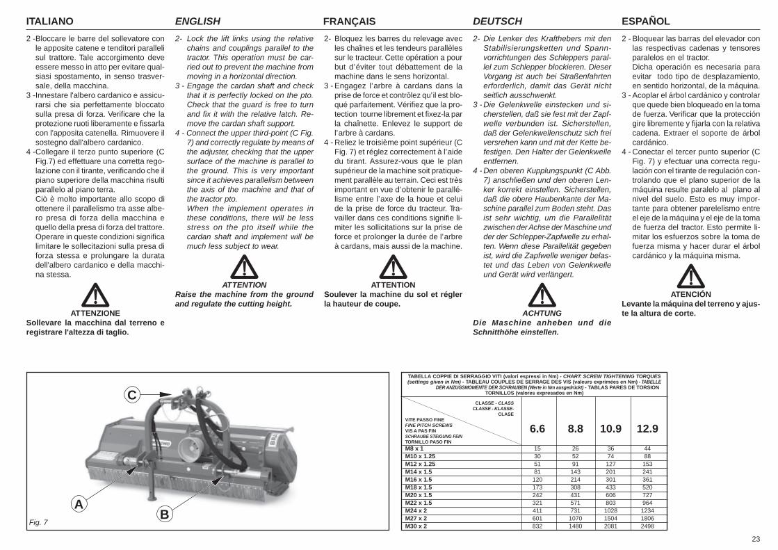
23
ITALIANO ENGLISH FRANÇAIS ESPAÑOLDEUTSCH
Fig. 7
AB
C
TABELLA COPPIE DI SERRAGGIO VITI (valori espressi in Nm) - CHART: SCREW TIGHTENING TORQUES(settings given in Nm) - TABLEAU COUPLES DE SERRAGE DES VIS (valeurs exprimées en Nm) - TABELLE
DER ANZUGSMOMENTE DER SCHRAUBEN (Werte in Nm ausgedrückt) - TABLAS PARES DE TORSIONTORNILLOS (valores expresados en Nm)
CLASSE - CLASSCLASSE - KLASSE-
CLASEVITE PASSO FINEFINE PITCH SCREWSVIS A PAS FIN 6.6 8.8 10.9 12.9SCHRAUBE STEIGUNG FEINTORNILLO PASO FIN
M8 x 1 15 26 36 44M10 x 1.25 30 52 74 88M12 x 1.25 51 91 127 153M14 x 1.5 81 143 201 241M16 x 1.5 120 214 301 361M18 x 1.5 173 308 433 520M20 x 1.5 242 431 606 727M22 x 1.5 321 571 803 964M24 x 2 411 731 1028 1234M27 x 2 601 1070 1504 1806M30 x 2 832 1480 2081 2498
2 -Bloccare le barre del sollevatore conle apposite catene e tenditori parallelisul trattore. Tale accorgimento deveessere messo in atto per evitare qual-siasi spostamento, in senso trasver-sale, della macchina.
3 -Innestare l'albero cardanico e assicu-rarsi che sia perfettamente bloccatosulla presa di forza. Verificare che laprotezione ruoti liberamente e fissarlacon l'apposita catenella. Rimuovere ilsostegno dall'albero cardanico.
4 -Collegare il terzo punto superiore (CFig.7) ed effettuare una corretta rego-lazione con il tirante, verificando che ilpiano superiore della macchina risultiparallelo al piano terra.Ciò è molto importante allo scopo diottenere il parallelismo tra asse albe-ro presa di forza della macchina equello della presa di forza del trattore.Operare in queste condizioni significalimitare le sollecitazioni sulla presa diforza stessa e prolungare la duratadell'albero cardanico e della macchi-na stessa.
ATTENZIONESollevare la macchina dal terreno eregistrare l'altezza di taglio.
2- Lock the lift links using the relativechains and couplings parallel to thetractor. This operation must be car-ried out to prevent the machine frommoving in a horizontal direction.
3 - Engage the cardan shaft and checkthat it is perfectly locked on the pto.Check that the guard is free to turnand fix it with the relative latch. Re-move the cardan shaft support.
4 - Connect the upper third-point (C Fig.7) and correctly regulate by means ofthe adjuster, checking that the uppersurface of the machine is parallel tothe ground. This is very importantsince it achieves parallelism betweenthe axis of the machine and that ofthe tractor pto.When the implement operates inthese conditions, there will be lessstress on the pto itself while thecardan shaft and implement will bemuch less subject to wear.
ATTENTIONRaise the machine from the groundand regulate the cutting height.
2- Bloquez les barres du relevage avecles chaînes et les tendeurs parallèlessur le tracteur. Cette opération a pourbut d’éviter tout débattement de lamachine dans le sens horizontal.
3 - Engagez l’arbre à cardans dans laprise de force et contrôlez qu’il est blo-qué parfaitement. Vérifiez que la pro-tection tourne librement et fixez-la parla chaînette. Enlevez le support del’arbre à cardans.
4 - Reliez le troisième point supérieur (CFig. 7) et réglez correctement à l’aidedu tirant. Assurez-vous que le plansupérieur de la machine soit pratique-ment parallèle au terrain. Ceci est trèsimportant en vue d’obtenir le parallé-lisme entre l’axe de la houe et celuide la prise de force du tracteur. Tra-vailler dans ces conditions signifie li-miter les sollicitations sur la prise deforce et prolonger la durée de l’arbreà cardans, mais aussi de la machine.
ATTENTIONSoulever la machine du sol et réglerla hauteur de coupe.
2- Die Lenker des Krafthebers mit denStabilisierungsketten und Spann-vorrichtungen des Schleppers paral-lel zum Schlepper blockieren. DieserVorgang ist auch bei Straßenfahrtenerforderlich, damit das Gerät nichtseitlich ausschwenkt.
3 - Die Gelenkwelle einstecken und si-cherstellen, daß sie fest mit der Zapf-welle verbunden ist. Sicherstellen,daß der Gelenkwellenschutz sich freiversrehen kann und mit der Kette be-festigen. Den Halter der Gelenkwelleentfernen.
4 - Den oberen Kupplungspunkt (C Abb.7) anschließen und den oberen Len-ker korrekt einstellen. Sicherstellen,daß die obere Haubenkante der Ma-schine parallel zum Boden steht. Dasist sehr wichtig, um die Parallelitätzwischen der Achse der Maschine undder der Schlepper-Zapfwelle zu erhal-ten. Wenn diese Parallelität gegebenist, wird die Zapfwelle weniger belas-tet und das Leben von Gelenkwelleund Gerät wird verlängert.
ACHTUNGDie Maschine anheben und dieSchnitthöhe einstellen.
2 - Bloquear las barras del elevador conlas respectivas cadenas y tensoresparalelos en el tractor.Dicha operación es necesaria paraevitar todo tipo de desplazamiento,en sentido horizontal, de la máquina.
3 - Acoplar el árbol cardánico y controlarque quede bien bloqueado en la tomade fuerza. Verificar que la proteccióngire libremente y fijarla con la relativacadena. Extraer el soporte de árbolcardánico.
4 - Conectar el tercer punto superior (CFig. 7) y efectuar una correcta regu-lación con el tirante de regulación con-trolando que el plano superior de lamáquina resulte paralelo al plano alnivel del suelo. Esto es muy impor-tante para obtener parelelismo entreel eje de la máquina y el eje de la tomade fuerza del tractor. Esto permite li-mitar los esfuerzos sobre la toma defuerza misma y hacer durar el árbolcardánico y la máquina misma.
ATENCIÓNLevante la máquina del terreno y ajus-te la altura de corte.
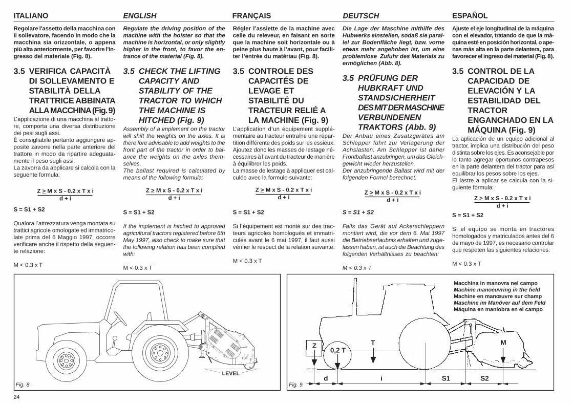
ITALIANO ENGLISH FRANÇAIS ESPAÑOLDEUTSCH
24
Regolare l'assetto della macchina conil sollevatore, facendo in modo che lamacchina sia orizzontale, o appenapiù alta anteriormente, per favorire l'in-gresso del materiale (Fig. 8).
3.5 VERIFICA CAPACITÀDI SOLLEVAMENTO ESTABILITÀ DELLATRATTRICE ABBINATAALLA MACCHINA (Fig. 9)
L’applicazione di una macchina al tratto-re, comporta una diversa distribuzionedei pesi sugli assi.È consigliabile pertanto aggiungere ap-posite zavorre nella parte anteriore deltrattore in modo da ripartire adeguata-mente il peso sugli assi.La zavorra da applicare si calcola con laseguente formula:
S = S1 + S2
Qualora l’attrezzatura venga montata sutrattici agricole omologate ed immatrico-late prima del 6 Maggio 1997, occorreverificare anche il rispetto della seguen-te relazione:
M < 0.3 x T
Regulate the driving position of themachine with the hoister so that themachine is horizontal, or only slightlyhigher in the front, to favor the en-trance of the material (Fig. 8).
3.5 CHECK THE LIFTINGCAPACITY ANDSTABILITY OF THETRACTOR TO WHICHTHE MACHINE ISHITCHED (Fig. 9)
Assembly of a implement on the tractorwill shift the weights on the axles. It isthere fore advisable to add weights to thefront part of the tractor in order to bal-ance the weights on the axles them-selves.The ballast required is calculated bymeans of the following formula:
S = S1 + S2
If the implement is hitched to approvedagricultural tractors registered before 6thMay 1997, also check to make sure thatthe following relation has been compliedwith:
M < 0.3 x T
Régler l’assiette de la machine aveccelle du releveur, en faisant en sorteque la machine soit horizontale ou àpeine plus haute à l’avant, pour facili-ter l’entrée du matériau (Fig. 8).
3.5 CONTROLE DESCAPACITÉS DELEVAGE ETSTABILITÉ DUTRACTEUR RELIÉ ALA MACHINE (Fig. 9)
L’application d’un équipement supplé-mentaire au tracteur entraîne une répar-tition différente des poids sur les essieux.Ajoutez donc les masses de lestage né-cessaires à l’avant du tracteur de manièreà équilibrer les poids.La masse de lestage à appliquer est cal-culée avec la formule suivante:
S = S1 + S2
Si l’équipement est monté sur des trac-teurs agricoles homologués et immatri-culés avant le 6 mai 1997, il faut aussivérifier le respect de la relation suivante:
M < 0.3 x T
Ajuste el eje longitudinal de la máquinacon el elevador, tratando de que la má-quina esté en posición horizontal, o ape-nas más alta en la parte delantera, parafavorecer el ingreso del material (Fig. 8).
3.5 CONTROL DE LACAPACIDAD DEELEVACIÓN Y LAESTABILIDAD DELTRACTORENGANCHADO EN LAMÁQUINA (Fig. 9)
La aplicación de un equipo adicional altractor, implica una distribución del pesodistinta sobre los ejes. Es aconsejable porlo tanto agregar oportunos contrapesosen la parte delantera del tractor para asíequilibrar los pesos sobre los ejes.El lastre a aplicar se calcula con la si-guiente fórmula:
S = S1 + S2
Si el equipo se monta en tractoreshomologados y matriculados antes del 6de mayo de 1997, es necesario controlarque respeten las siguientes relaciones:
M < 0.3 x T
Die Lage der Maschine mithilfe desHubwerks einstellen, sodaß sie paral-lel zur Bodenfläche liegt, bzw. vorneetwas mehr angehoben ist, um eineproblemlose Zufuhr des Materials zuermöglichen (Abb. 8).
3.5 PRÜFUNG DERHUBKRAFT UNDSTANDSICHERHEITDES MIT DER MASCHINEVERBUNDENENTRAKTORS (Abb. 9)
Der Anbau eines Zusatzgerätes amSchlepper führt zur Verlagerung derAchslasten. Am Schlepper ist daherFrontballast anzubringen, um das Gleich-gewicht wieder herzustellen.Der anzubringende Ballast wird mit derfolgenden Formel berechnet:
S = S1 + S2
Falls das Gerät auf Ackerschleppernmontiert wird, die vor dem 6. Mai 1997die Betriebserlaubnis erhalten und zuge-lassen haben, ist auch die Beachtung desfolgenden Verhältnisses zu beachten:
M < 0.3 x T
Z > M x S - 0.2 x T x id + i
Z > M x S - 0.2 x T x id + i
Z > M x S - 0.2 x T x id + i
Z > M x S - 0.2 x T x id + i Z > M x S - 0.2 x T x i
d + i
Fig. 8
LEVEL
Fig. 9
Z0,2 T
T M
S2S1id
Macchina in manovra nel campoMachine manoeuvring in the fieldMachine en manœuvre sur champMaschine im Manöver auf dem FeldMáquina en maniobra en el campo

25
ITALIANO ENGLISH FRANÇAIS ESPAÑOLDEUTSCH
I = interasse ruota trattrice (cm).d = distanza dell’asse anteriore dalle
zavorre (cm).T = massa della trattrice + operatore
(75 kg).Z = massa della zavorra.M = massa della macchina operatrice
(kg).S = sbalzo dall’asse posteriore della
macchina operatrice (cm).S1 = distanza dall’asse posteriore all’at-
tacco parallele (cm).S2 = distanza tra foro attacchi barre e
baricentro macchina operatrice(cm).
3.6 ALBERO CARDANICOL'angolazione in cui lavora l'alberocardanico deve essere la minima possi-bile, (non superare i 10÷15 gradi), que-sto favorisce la durata sia dell'albero chedella macchina (Fig. 6).
CAUTELALeggere attentamente il libretto diistruzioni che la Casa Costruttrice delcardano applica allo stesso.Se usurato o rotto, sostituirlo con uncardano marcato «CE».
CAUTELA- Il costruttore dell'albero cardanico
raccomanda di non modificarlo.È vietato quindi effettuare modifichee adattamenti vari.
- Essendo un organo che ruota a ve-locità sostenuta, in fase di collaudoviene sottoposto a bilanciatura, e glieventuali interventi di modifica po-trebbero causare scompensi che siriperquoterebbero nella funzionali-tà della macchina stessa oltrechèsull'integrità dell'albero stesso.
- Quando è sfilato al massimo, in ognicondizione di lavoro i tubi telescopi-ci devono sovrapporsi per almeno 1/3 della loro lunghezza (A Fig. 10).
I = tractor wheelbase (cm)d = distance of front axle from ballast
(cm)T = weight of tractor + operator (75 kg)Z = weight of ballast (kg)M = weight of implement (kg)S = overhang from rear axle of the
machine (cm)S1 = distance of rear axle from parallel
hitch (cm)S2 = distance between bar hitch hole
and center of gravity of machine(cm)
3.6 CARDAN SHAFTThe working angulation of the cardanshaft must be the minimum possible (notto exceed 10 -15°).This prolongs the duration of both shaftand machine (Fig. 6).
CAUTIONCarefully read the instruction bookletwhich the constructing company ofthe cardan shaft includes with it.If worn or broken, replace it with acardan marked «EC».
CAUTION- The constructor of the cardan shaft
recommends not modifying it.- It is therefore forbidden to effect
modifications or adjustments of anykind.
- It is a machine part that rotates at asteady speed and, during the test-ing phase, is submitted to balanc-ing, therefore any modificationscould cause unbalance which mightreflect on the working of the ma-chine and on the integrity of theshaft itself.
- When is withdrawn to the maximum,in every working condition, thetubes must overlap for at least 1/3of their length (A Fig. 10).
I = Entraxe roue tracteur (cm).d = Distance des masses de l’essieu
avant (cm).T = Masse du tracteur + opérateur (75
kg).Z = Poids de la masse de lestage (kg).M = Masse de la machine opération-
nelle (kg).S = Saillie de l’essieu arrière de la
machine opérationnelle (cm).S1 = distance de l’essieu arrière à l’at-
telage parallèle (cm).S2 = distance entre le trou d’attelages
de barres et le centre de gravitéde la machine opérationnelle (cm).
3.6 ARBRE A CARDANSL’angle de travail de l’arbre à cardan doitêtre le plus petit possible (ne pas dépas-ser 10÷15 degrés), ce qui favorise la du-rée aussi bien de l’arbre que de la ma-chine (Fig. 6).
PRUDENCELire attentivement le mode d’emploique le Constructeur fournit avec lecardan. Si le cardan est abîmé ou usé,le remplacer contre un cardan portantle label CE.
PRUDENCE- Le constructeur de l’arbre à cardan
recommande de ne pas le modifier.Il est donc interdit d’effectuer desmodifications ou des adaptations.
- Comme est un organe qui tourne àune vitesse soutenue, il est soumisà un équilibrage en phase d’essai etles modifications éventuelles pour-raient provoquer un déséquilibre quise répercuterait aussi bien sur lecaractère fonctionnel de la machineque sur l’intégrité de l’arbre.
- Dans toutes les conditions de tra-vail, quand est déboîté au maxi-mum, les tubes télescopiques doi-vent se superposer sur au moins 1/3 de leur longueur (A Fig. 10).
I = Radabstand Traktor (cm)d = Abstand Vorderachse/Ballast (cm)T = Gewicht Traktor + Fahrer (75 kg)M = Gewicht Ballast (kg)S = Überstand der Arbeitsmaschine
zur Hinterachse (cm)S1 = Abstand von der Hinterachse zum
Anschluss der Parallelgestänge(cm)
S2 = Abstand zwischen Loch Balken-kupplungen und Schwerpunkt Ar-beitsmaschine (cm)
3.6 GELENKWELLEDer Arbeitswinkel der Kardanwelle hatminimal zu sein (nicht mehr als 10-15Grad); dadurch wird eine längere Dauerder Kardanwelle, sowie der Maschineselbst gewährleistet (Abb. 6).
VORSICHTDie Gebrauchsanleitung der Hersteller-firma der Kardanwelle ist aufmerksamzu lesen. Sollte die Kardanwelle beschä-digt oder abgenutzt sein, so ist sie un-verzüglich mit einer neuen Kardanwel-le mit CE - Markenzeichen zu ersetzen.
VORSICHT- Die Herstellerfirma der Kardanwel-
le weist darauf hin, unter keinenUmständen verändert werden darf.Ein Abändern zur Anpassung an di-verse Betriebsbedingungen ist da-her nicht gestattet.
- Ein langsam rotierendes Maschi-nenorgan ist, wird sie bei der Abnah-meprüfung ausgewuchtet. Eventu-ell an der Kardanwelle ausgeführteAbänderungen würden daher zu ei-ner Verfälschung dieses Gleichge-wichtszustandes und daraus fol-gend zu Schäden an der Maschine,sowie an der Welle selbst führen.
- Ist die maximal ausgefahren, somüssen die Teleskoprohre bei jederBetriebsart für mindestens ein Drit-tel ihrer Länge übereinander gela-gert sein (A Abb. 10).
I = distancia entre ejes rueda tractor(cm)
d = distancia entre el eje delantero ylos lastres (cm)
T = masa del tractor + operador (75 kg)Z = masa del lastre (kg)M = masa de la máquina operadora
(kg)S = salto del eje trasero de la máquina
operadora (cm)S1 = distancia entre el eje trasero y el
enganche paralelo (cm)S2 = distancia entre el agujero engan-
che barras y el centro de grave-dad máquina operadora (cm).
3.6 ARBOL CARDANICOEl ángulo en el cual trabaja el árbolcardán tiene que ser el mínimo posible(no supere los 10 ÷ 15 grados), ésto fa-vorece la duración tanto del árbol comode la máquina (Fig. 6).
ADVERTENCIALea atentamente el manual de instruc-ciones del productor del árbol cardán.Si está desgastado o roto, sustitúya-lo con un cardán con la marca «CE».
ADVERTENCIA- El fabricante del árbol cardán acon-
seja no modificar el mismo.- Está prohibido efectuar modifica-
ciones y adaptaciones varias.- Dado que es un órgano que gira a
velocidad constante, es equilibradodurante la prueba, y las modificacio-nes podrían causar descompensa-ciones que repercutirían en el fun-cionamiento de la máquina y en laintegridad del árbol mismo.
- Cuando está extraído al máximo, entodas las condiciones de trabajo,los tubos telescópicos tienen quesuperponerse por 1/3 al menos dela propia longitud (A Fig. 10).
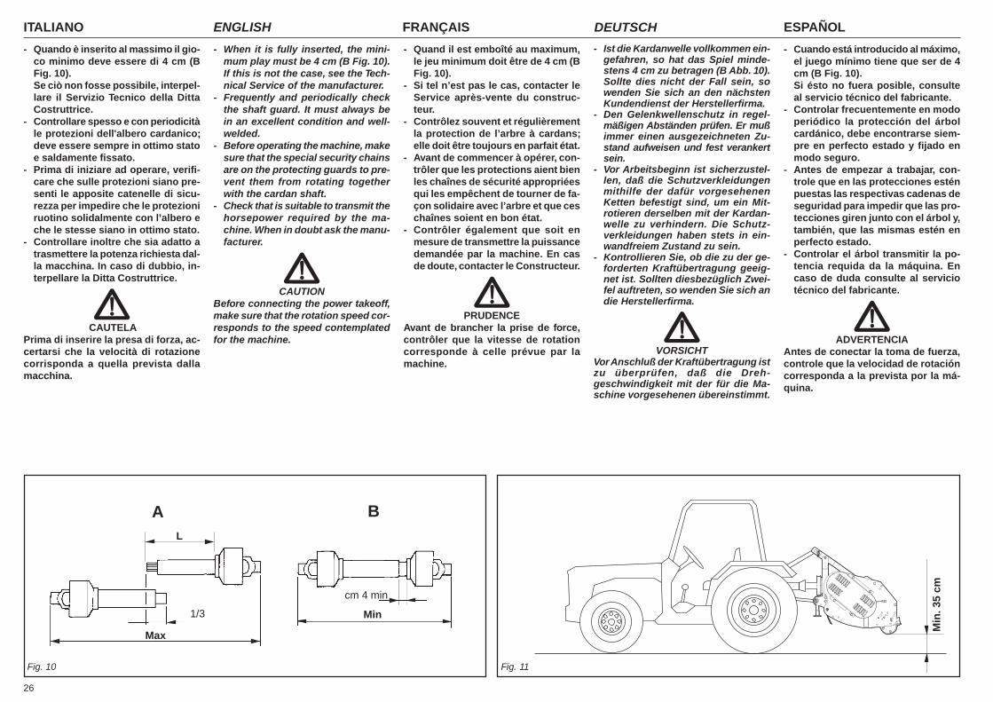
ITALIANO ENGLISH FRANÇAIS ESPAÑOLDEUTSCH
26
- Quando è inserito al massimo il gio-co minimo deve essere di 4 cm (BFig. 10).Se ciò non fosse possibile, interpel-lare il Servizio Tecnico della DittaCostruttrice.
- Controllare spesso e con periodicitàle protezioni dell'albero cardanico;deve essere sempre in ottimo statoe saldamente fissato.
- Prima di iniziare ad operare, verifi-care che sulle protezioni siano pre-senti le apposite catenelle di sicu-rezza per impedire che le protezioniruotino solidalmente con l’albero eche le stesse siano in ottimo stato.
- Controllare inoltre che sia adatto atrasmettere la potenza richiesta dal-la macchina. In caso di dubbio, in-terpellare la Ditta Costruttrice.
CAUTELAPrima di inserire la presa di forza, ac-certarsi che la velocità di rotazionecorrisponda a quella prevista dallamacchina.
- When it is fully inserted, the mini-mum play must be 4 cm (B Fig. 10).If this is not the case, see the Tech-nical Service of the manufacturer.
- Frequently and periodically checkthe shaft guard. It must always bein an excellent condition and well-welded.
- Before operating the machine, makesure that the special security chainsare on the protecting guards to pre-vent them from rotating togetherwith the cardan shaft.
- Check that is suitable to transmit thehorsepower required by the ma-chine. When in doubt ask the manu-facturer.
CAUTIONBefore connecting the power takeoff,make sure that the rotation speed cor-responds to the speed contemplatedfor the machine.
- Ist die Kardanwelle vollkommen ein-gefahren, so hat das Spiel minde-stens 4 cm zu betragen (B Abb. 10).Sollte dies nicht der Fall sein, sowenden Sie sich an den nächstenKundendienst der Herstellerfirma.
- Den Gelenkwellenschutz in regel-mäßigen Abständen prüfen. Er mußimmer einen ausgezeichneten Zu-stand aufweisen und fest verankertsein.
- Vor Arbeitsbeginn ist sicherzustel-len, daß die Schutzverkleidungenmithilfe der dafür vorgesehenenKetten befestigt sind, um ein Mit-rotieren derselben mit der Kardan-welle zu verhindern. Die Schutz-verkleidungen haben stets in ein-wandfreiem Zustand zu sein.
- Kontrollieren Sie, ob die zu der ge-forderten Kraftübertragung geeig-net ist. Sollten diesbezüglich Zwei-fel auftreten, so wenden Sie sich andie Herstellerfirma.
VORSICHTVor Anschluß der Kraftübertragung istzu überprüfen, daß die Dreh-geschwindigkeit mit der für die Ma-schine vorgesehenen übereinstimmt.
- Quand il est emboîté au maximum,le jeu minimum doit être de 4 cm (BFig. 10).
- Si tel n’est pas le cas, contacter leService après-vente du construc-teur.
- Contrôlez souvent et régulièrementla protection de l’arbre à cardans;elle doit être toujours en parfait état.
- Avant de commencer à opérer, con-trôler que les protections aient bienles chaînes de sécurité appropriéesqui les empêchent de tourner de fa-çon solidaire avec l’arbre et que ceschaînes soient en bon état.
- Contrôler également que soit enmesure de transmettre la puissancedemandée par la machine. En casde doute, contacter le Constructeur.
PRUDENCEAvant de brancher la prise de force,contrôler que la vitesse de rotationcorresponde à celle prévue par lamachine.
- Cuando está introducido al máximo,el juego mínimo tiene que ser de 4cm (B Fig. 10).Si ésto no fuera posible, consulteal servicio técnico del fabricante.
- Controlar frecuentemente en modoperiódico la protección del árbolcardánico, debe encontrarse siem-pre en perfecto estado y fijado enmodo seguro.
- Antes de empezar a trabajar, con-trole que en las protecciones esténpuestas las respectivas cadenas deseguridad para impedir que las pro-tecciones giren junto con el árbol y,también, que las mismas estén enperfecto estado.
- Controlar el árbol transmitir la po-tencia requida da la máquina. Encaso de duda consulte al serviciotécnico del fabricante.
ADVERTENCIAAntes de conectar la toma de fuerza,controle que la velocidad de rotacióncorresponda a la prevista por la má-quina.
Fig. 10 Fig. 11
Min
cm 4 min
Max
A BL
1/3
Min
. 35
cm
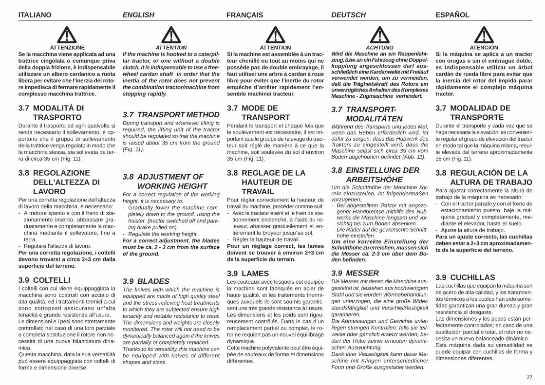
27
ITALIANO ENGLISH FRANÇAIS ESPAÑOLDEUTSCH
ATTENZIONESe la macchina viene applicata ad unatrattrice cingolata o comunque privadella doppia frizione, è indispensabileutilizzare un albero cardanico a ruotalibera per evitare che l'inerzia del roto-re impedisca di fermare rapidamente ilcomplesso macchina trattrice.
3.7 MODALITÀ DITRASPORTO
Durante il trasporto ed ogni qualvolta sirenda necessario il sollevamento, è op-portuno che il gruppo di sollevamentodella trattrice venga regolato in modo chela macchina stessa, sia sollevata da ter-ra di circa 35 cm (Fig. 11).
3.8 REGOLAZIONEDELL'ALTEZZA DILAVORO
Per una corretta regolazione dell'altezzadi lavoro della macchina, è necessario:- A trattore spento e con il freno di sta-
zionamento inserito, abbassare gra-duatamente e completamente la mac-china mediante il sollevatore, fino aterra.
- Regolare l'altezza di lavoro.Per una corretta regolazione, i coltellidevono trovarsi a circa 2÷3 cm dallasuperficie del terreno.
3.9 COLTELLII coltelli con cui viene equippaggiata lamacchina sono costruiti con acciaio dialta qualità, ed i trattamenti termici a cuisono sottoposti assicurano un'altatenacità e grande resistenza all'usura.Le dimensioni e i pesi sono strettamentecontrollati; nel caso di una loro parzialeo completa sostituzione il rotore non ne-cessità di una nuova bilanciatura dina-mica.Questa macchina, data la sua versatilitàpuò essere equippaggiata con coltelli diforma e dimensione diverse.
ATTENTIONIf the machine is hooked to a caterpil-lar tractor, or one without a doubleclutch, it is indispensable to use a free-wheel cardan shaft in order that theinertia of the rotor does not preventthe combination tractor/machine fromstopping rapidly.
3.7 TRANSPORT METHODDuring transport and whenever lifting isrequired, the lifting unit of the tractorshould be regulated so that the machineis raised about 35 cm from the ground(Fig. 11).
3.8 ADJUSTMENT OFWORKING HEIGHT
For a correct regulation of the workingheight, it is necessary to:- Gradually lower the machine com-
pletely down to the ground, using thehoister (tractor switched off and park-ing brake pulled on).
- Regulate the working height.For a correct adjustment, the bladesmust be ca. 2 - 3 cm from the surfaceof the ground.
3.9 BLADESThe knives with which the machine isequipped are made of high quality steeland the stress-relieving heat treatmentsto which they are subjected ensure hightenacity and notable resistance to wear.The dimensions and weights are closelymonitored. The rotor will not need to bedynamically balanced again if the knivesare partially or completely replaced.Thanks to its versatility, this machine canbe equipped with knives of differentshapes and sizes.
ACHTUNGWird die Maschine an ein Raupenfahr-zeug, bzw. an ein Fahrzeug ohne Doppel-kupplung angeschlossen darf aus-schließlich eine Kardanwelle mit Freilaufverwendet werden, um zu vermeiden,daß die Trägheitskraft des Rotors einunverzügliches Anhalten des KomplexesMaschine - Zugmaschine verhindert.
3.7 TRANSPORT-MODALITÄTEN
Während des Transports und jedes Mal,wenn das Heben erforderlich wird, istdafür zu sorgen, dass das Hubwerk desTraktors zu eingestellt wird, dass dieMaschine selbst sich circa 35 cm vomBoden abgehobnen befindet (Abb. 11).
3.8 EINSTELLUNG DERARBEITSHÖHE
Um die Schnitthöhe der Maschine kor-rekt einzustellen, ist folgendermaßenvorzugehen:- Bei abgestelltem Traktor mit angezo-
gener Handbremse mithilfe des Hub-werks die Maschine langsam und vor-sichtig bis zum Boden absenken.
- Die Räder auf die gewünschte Schnitt-höhe einstellen.
Um eine korrekte Einstellung derSchnitthöhe zu erreichen, müssen sichdie Messer ca. 2-3 cm über dem Bo-den befinden.
3.9 MESSERDie Messer, mit denen die Maschine aus-gestattet ist, bestehen aus hochwertigemStahl und sie wurden Wärmebehandlun-gen unterzogen, die eine große Wider-standsfähigkeit und Verschleißfestigkeitgarantieren.Die Abmessungen und Gewichte unter-liegen strengen Kontrollen; falls sie teil-weise oder gänzlich ersetzt werden, be-darf der Rotor keiner erneuten dynami-schen Auswuchtung.Dank ihrer Vielseitigkeit kann diese Ma-schine mit Klingen unterschiedlicherForm und Größe ausgestattet werden.
ATTENTIONSi la machine est assemblée à un trac-teur chenillé ou tout au moins qui nepossède pas de double embrayage, ilfaut utiliser une arbre à cardan à rouelibre pour éviter que l’inertie du rotorempêche d’arrêter rapidement l’en-semble machine/ tracteur.
3.7 MODE DETRANSPORT
Pendant le transport et chaque fois quele soulèvement est nécessaire, il est im-portant que le groupe de relevage du trac-teur soit réglé de manière à ce que lamachine, soit soulevée du sol d’environ35 cm (Fig. 11).
3.8 REGLAGE DE LAHAUTEUR DETRAVAIL
Pour régler correctement la hauteur detravail du machine, procéder comme suit:- Avec le tracteur éteint et le frein de sta-
tionnement enclenché, à l’aide du re-leveur, abaisser graduellement et en-tièrement le broyeur jusqu’au sol.
- Régler la hauteur de travail.Pour un réglage correct, les lamesdoivent se trouver à environ 2÷3 cmde la superficie du terrain.
3.9 LAMESLes couteaux avec lesquels est équipéela machine sont fabriqués en acier dehaute qualité, et les traitements thermi-ques auxquels ils sont soumis garantis-sent une très grande résistance à l’usure.Les dimensions et les poids sont rigou-reusement contrôlés. Dans le cas d’unremplacement partiel ou complet, le ro-tor ne requiert pas un nouvel équilibragedynamique.Cette machine polyvalente peut être équi-pée de couteaux de forme et dimensionsdifférentes.
ATENCIÓNSi la máquina se aplica a un tractorcon orugas o sin el embrague doble,es indispensable utilizar un árbolcardán de rueda libre para evitar quela inercia del rotor del impida pararrápidamente el complejo máquinatractor.
3.7 MODALIDAD DETRANSPORTE
Durante el transporte y cada vez que sehaga necesaria la elevación, es convenien-te regular el grupo de elevación del tractoren modo tal que la máquina misma, resul-te elevada del terreno aproximadamente35 cm (Fig. 11).
3.8 REGULACIÓN DE LAALTURA DE TRABAJO
Para ajustar correctamente la altura detrabajo de la máquina es necesario:- Con el tractor parado y con el freno de
estacionamiento puesto, baje la má-quina gradual y completamente, me-diante el elevador, hasta el suelo.
- Ajuste la altura de trabajo.Para un ajuste correcto, las cuchillasdeben estar a 2÷3 cm aproximadamen-te de la superficie del terreno.
3.9 CUCHILLASLas cuchillas que equipan la máquina sonde acero de alta calidad, y los tratamien-tos térmicos a los cuales han sido some-tidas garantizan una gran dureza y granresistencia al desgaste.Las dimensiones y los pesos están per-fectamente controlados; en caso de unasustitución parcial o total, el rotor no ne-cesita un nuevo balanceado dinámico.Esta máquina dada su versatilidad sepuede equipar con cuchillas de forma ydimensiones diferentes.
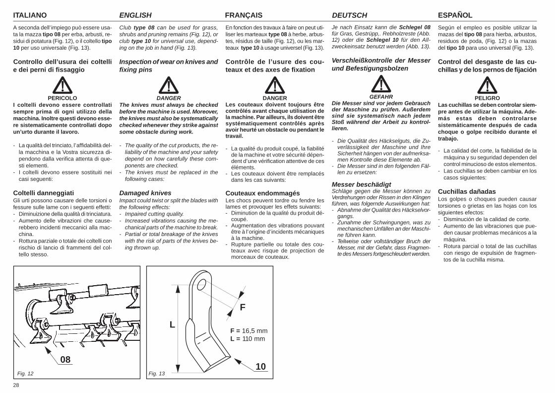
ITALIANO ENGLISH FRANÇAIS ESPAÑOLDEUTSCH
28
A seconda dell’impiego può essere usa-ta la mazza tipo 08 per erba, arbusti, re-sidui di potatura (Fig. 12), o il coltello tipo10 per uso universale (Fig. 13).
Controllo dell’usura dei coltellie dei perni di fissaggio
PERICOLOI coltelli devono essere controllatisempre prima di ogni utilizzo dellamacchina. Inoltre questi devono esse-re sistematicamente controllati dopoun’urto durante il lavoro.
- La qualità del trinciato, l’affidabilità del-la macchina e la Vostra sicurezza di-pendono dalla verifica attenta di que-sti elementi.
- I coltelli devono essere sostituiti neicasi seguenti:
Coltelli danneggiatiGli urti possono causare delle torsioni ofessure sulle lame con i seguenti effetti:- Diminuizione della qualità di trinciatura.- Aumento delle vibrazioni che cause-
rebbero incidenti meccanici alla mac-china.
- Rottura parziale o totale dei coltelli conrischio di lancio di frammenti del col-tello stesso.
Club type 08 can be used for grass,shrubs and pruning remains (Fig. 12), orclub type 10 for universal use, depend-ing on the job in hand (Fig. 13).
Inspection of wear on knives andfixing pins
DANGERThe knives must always be checkedbefore the machine is used. Moreover,the knives must also be systematicallychecked whenever they strike againstsome obstacle during work.
- The quality of the cut products, the re-liability of the machine and your safetydepend on how carefully these com-ponents are checked.
- The knives must be replaced in thefollowing cases:
Damaged knivesImpact could twist or split the blades withthe following effects:- Impaired cutting quality.- Increased vibrations causing the me-
chanical parts of the machine to break.- Partial or total breakage of the knives
with the risk of parts of the knives be-ing thrown up.
Je nach Einsatz kann die Schlegel 08für Gras, Gestrüpp,. Rebholzreste (Abb.12) oder die Schlegel 10 für den All-zweckeinsatz benutzt werden (Abb. 13).
Verschleißkontrolle der Messerund Befestigungsbolzen
GEFAHRDie Messer sind vor jedem Gebrauchder Maschine zu prüfen. Außerdemsind sie systematisch nach jedemStoß während der Arbeit zu kontrol-lieren.
- Die Qualität des Häckselguts, die Zu-verlässigkeit der Maschine und IhreSicherheit hängen von der aufmerksa-men Kontrolle diese Elemente ab.
- Die Messer sind in den folgenden Fäl-len zu ersetzen:
Messer beschädigtSchläge gegen die Messer können zuVerdrehungen oder Rissen in den Klingenführen, was folgernde Auswirkungen hat:- Abnahme der Qualität des Häckselvor-
gangs.- Zunahme der Schwingungen, was zu
mechanischen Unfällen an der Maschi-ne führen kann.
- Teilweise oder vollständiger Bruch derMesser, mit der Gefahr, dass Fragmen-te des Messers fortgeschleudert werden.
En fonction des travaux à faire on peut uti-liser les marteaux type 08 à herbe, arbus-tes, résidus de taille (Fig. 12), ou les mar-teaux type 10 à usage universel (Fig. 13).
Contrôle de l’usure des cou-teaux et des axes de fixation
DANGERLes couteaux doivent toujours êtrecontrôlés avant chaque utilisation dela machine. Par ailleurs, ils doivent êtresystématiquement contrôlés aprèsavoir heurté un obstacle ou pendant letravail.
- La qualité du produit coupé, la fiabilitéde la machine et votre sécurité dépen-dent d’une vérification attentive de ceséléments.
- Les couteaux doivent être remplacésdans les cas suivants:
Couteaux endommagésLes chocs peuvent tordre ou fendre leslames et provoquer les effets suivants:- Diminution de la qualité du produit dé-
coupé.- Augmentation des vibrations pouvant
être à l’origine d’incidents mécaniquesà la machine.
- Rupture partielle ou totale des cou-teaux avec risque de projection demorceaux de couteaux.
Según el empleo es posible utilizar lamazas del tipo 08 para hierba, arbustos,residuos de poda, (Fig. 12) o la mazasdel tipo 10 para uso universal (Fig. 13).
Control del desgaste de las cu-chillas y de los pernos de fijación
PELIGROLas cuchillas se deben controlar siem-pre antes de utilizar la máquina. Ade-más estas deben controlarsesistemáticamente después de cadachoque o golpe recibido durante eltrabajo.
- La calidad del corte, la fiabilidad de lamáquina y su seguridad dependen delcontrol minucioso de estos elementos.
- Las cuchillas se deben cambiar en loscasos siguientes:
Cuchillas dañadasLos golpes o choques pueden causartorsiones o grietas en las hojas con lossiguientes efectos:- Disminución de la calidad de corte.- Aumento de las vibraciones que pue-
den causar problemas mecánicos a lamáquina.
- Rotura parcial o total de las cuchillascon riesgo de expulsión de fragmen-tos de la cuchilla misma.
08Fig. 12 Fig. 13
F
LF = 16,5 mmL = 110 mm
10

29
ITALIANO ENGLISH FRANÇAIS ESPAÑOLDEUTSCH
Coltelli usurati- Il diametro del foro di fissaggio «F» non
deve essere ovalizzato più 2 mm, ri-spetto al diametro originale (Fig. 14).
- La lunghezza «L» dei coltelli non puòscendere oltre 15 mm. rispetto la lun-ghezza originale (Fig. 14).
I perni devono essere sostituiti se:- La filettatura della vite di fissaggio «S»
è danneggiata.- L’usura «T» del perno è superiore a 2
mm (Fig. 14).
3.10 SOSTITUZIONE DEICOLTELLI
Verificare periodicamente lo stato deicoltelli ed il loro fissaggio.Sostituire immediatamente tutti i pezziusati e/o danneggiati con pezzi originalidella Ditta Costruttrice.Per la sostituzione dei coltelli usurati orotti, o parti danneggiate è necessario:- Posizionare la macchina e trattore in
piano.- Assicurarsi che tutti gli elementi rotati-
vi siano fermi.
Worn knives- The diameter of fixing hole «F» must
not be ovalized more than 2 mm in re-lation to the original diameter (Fig. 14).
- Length «L» of the knives must not beallowed to become more than 15 mmshorter than the original length (Fig. 14).
The pins must be replaced if:- The thread of fixing screw «S» is dam-
aged.- Wear «T» on pin exceeds 2 mm (Fig. 14).
3.10 REPLACING BLADESPeriodically check the knives and theirfixing components for wear.Immediately replace all worn and/or dam-aged parts with the Manufacturer’s genu-ine spares.Proceed in the following way to replaceworn or broken knives:- Park the machine and tractor on flat
ground.- Make sure that all turning components
have come to a stop.
Messer verschlissen- Der Durchmesser des Befestigungs-
lochs «F» darf im Bezug zum Original-durchmesser keine Unrundheit über 2mm aufweisen (Abb. 14).
- Die Länge «L» der Messer darf nichtweniger als 15 mm im Bezug zurOriginallänge ausmachen (Abb. 14).
Die Bolzen müssen ersetzt werden, wenn:- das Gewinde der Befestigungs-
schraube «S» beschädigt ist.- der Verschleiß «T» des Bolzens mehr
als 2 mm ausmacht (Abb. 14).
3.10 AUSWECHSELN DERMESSER
Den Zustand der Messer und ihrer Be-festigung regelmäßig prüfen.Alle verschlissenen und/oder beschädig-ten Teile sofort durch Originalersatzteileder Herstellerfirma ersetzen.Zum Ersetzen verschlissener oder beschä-digter Klingen ist wie folgt vorzugehen:- Die Maschine und den Traktor eben
abstellen.- Sicherstellen dass alle sich drehenden
Elemente zum Stehen gekommen sind.
Couteaux usés- Le diamètre du trou de fixation «F» ne
doit pas être ovalisé plus de 2 mm parrapport au diamètre d’origine (Fig. 14).
- La longueur «L» des couteaux ne peutpas être inférieure à 15 mm par rap-port à la longueur d’origine (Fig. 14).
Les axes doivent être remplacés si:- Le filetage de la vis de fixation «S» est
endommagé.- L’usure «T» de l’axe dépasse 2 mm
(Fig. 14).
3.10 CHANGEMENT DESLAMES
Contrôler régulièrement l’état des cou-teaux et leur fixation.Remplacer immédiatement toutes lespièces usées et/ou endommagées pardes pièces d’origine du fabricant.Pour le remplacement des couteaux usésou cassés et des pièces endommagées,il faut:- Placer la machine et le tracteur sur un
sol plat.- S’assurer que tous les éléments rota-
tifs sont arrêtés.
Cuchillas gastadas- El diámetro del orificio de fijación «F»
no se debe ovalar más de 2 mm, conrespecto al diámetro original (Fig. 14).
- La longitud «L» de las cuchillas nopuede disminuir más de 15 mm. conrespecto a la longitud original (Fig. 14).
Los pernos se deben sustituir si:- La rosca del tornillo de fijación «S» está
dañada.- El desgaste «T» del perno es mayor
de 2 mm (Fig. 14).
3.10 SUSTITUCIÓN DELAS CUCHILLAS
Controlar periódicamente el estado de lascuchillas y su fijación.Sustituir inmediatamente todas las pie-zas desgastadas y/o dañadas con pie-zas originales del fabricante.Para la sustitución de las cuchillas gas-tadas o rotas, o partes dañadas es ne-cesario:- Posicionar la máquina y tractor en un
lugar plano.- Verificar que todos los elementos de
rotación se encuentren detenidos.
Fig. 14
Diametro iniziale del foro (F)Initial diameter of the hole (F)Diamètre initial du trou (F) 16,5Anfangsdurchmesser des Lochs (F)Diámetro inicial del orificio (F)Diametro massimo ammissibile (F’)Maximum tolerated diameter (F’)Diamètre maximum admissible (F’) 18,5Höchstzulässiger Durchmesser (F’)Diámetro máximo admisible (F’)Lunghezza iniziale del coltello (L)Initial knife length (L)Longueur initiale du couteau (L) 110Anfangslänge des Messers (L)Longitud inicial de la cuchilla (L)Lunghezza minima accettabile (L’)Minimum acceptable length (L’)Longueur minimum admissible (L’) 95Kleinstzulässige Länge (L’)Longitud mínima aceptable (L’)Usura massima «T» del perno «S»Maximum wear «T» of pin «S»Usure maximum «T» de l’axe «S» 2Max. Verschleiß «T» des Bolzens «S»Desgaste máximo «T» del perno «S»
L
F
L’
F’
F
L
F’
L’
S T
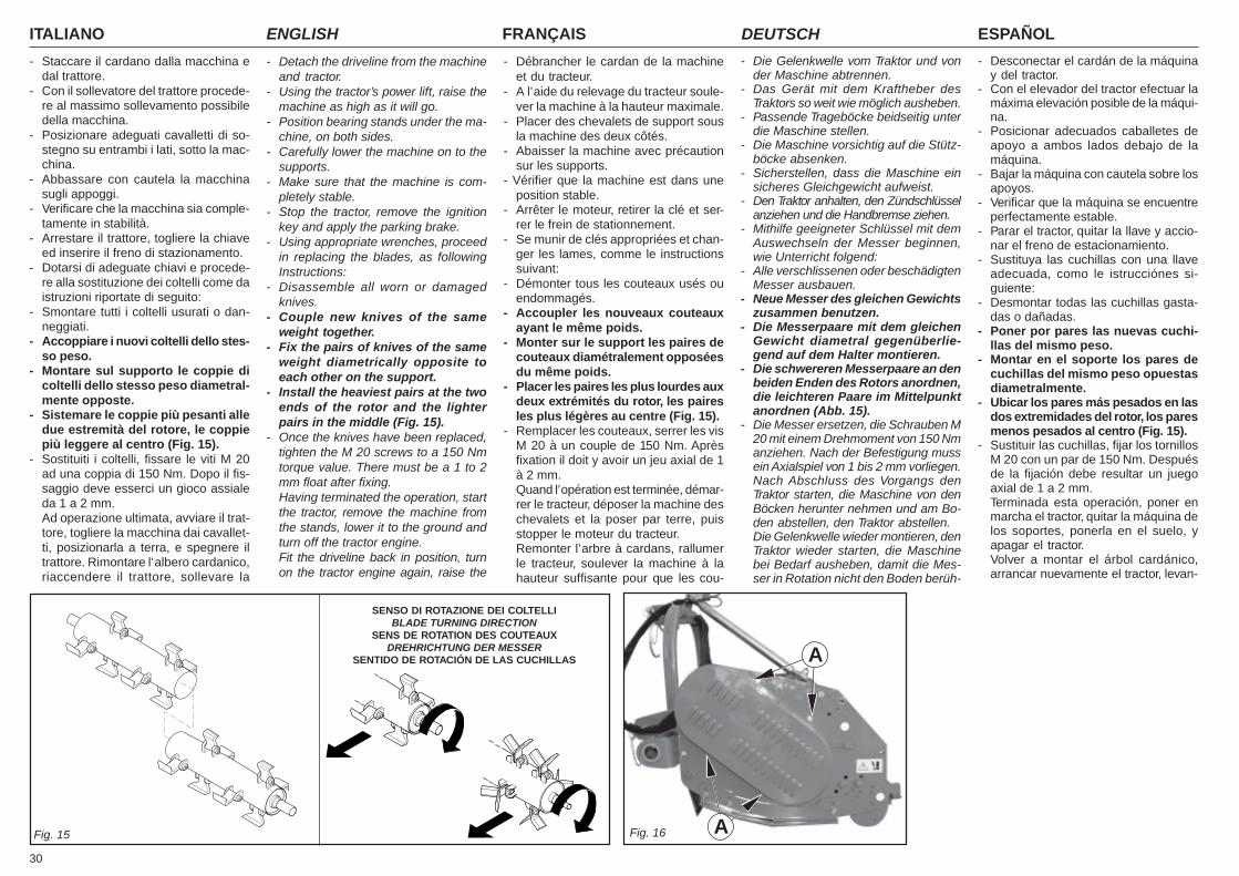
ITALIANO ENGLISH FRANÇAIS ESPAÑOLDEUTSCH
30
- Staccare il cardano dalla macchina edal trattore.
- Con il sollevatore del trattore procede-re al massimo sollevamento possibiledella macchina.
- Posizionare adeguati cavalletti di so-stegno su entrambi i lati, sotto la mac-china.
- Abbassare con cautela la macchinasugli appoggi.
- Verificare che la macchina sia comple-tamente in stabilità.
- Arrestare il trattore, togliere la chiaveed inserire il freno di stazionamento.
- Dotarsi di adeguate chiavi e procede-re alla sostituzione dei coltelli come daistruzioni riportate di seguito:
- Smontare tutti i coltelli usurati o dan-neggiati.
- Accoppiare i nuovi coltelli dello stes-so peso.
- Montare sul supporto le coppie dicoltelli dello stesso peso diametral-mente opposte.
- Sistemare le coppie più pesanti alledue estremità del rotore, le coppiepiù leggere al centro (Fig. 15).
- Sostituiti i coltelli, fissare le viti M 20ad una coppia di 150 Nm. Dopo il fis-saggio deve esserci un gioco assialeda 1 a 2 mm.Ad operazione ultimata, avviare il trat-tore, togliere la macchina dai cavallet-ti, posizionarla a terra, e spegnere iltrattore. Rimontare l’albero cardanico,riaccendere il trattore, sollevare la
- Detach the driveline from the machineand tractor.
- Using the tractor’s power lift, raise themachine as high as it will go.
- Position bearing stands under the ma-chine, on both sides.
- Carefully lower the machine on to thesupports.
- Make sure that the machine is com-pletely stable.
- Stop the tractor, remove the ignitionkey and apply the parking brake.
- Using appropriate wrenches, proceedin replacing the blades, as followingInstructions:
- Disassemble all worn or damagedknives.
- Couple new knives of the sameweight together.
- Fix the pairs of knives of the sameweight diametrically opposite toeach other on the support.
- Install the heaviest pairs at the twoends of the rotor and the lighterpairs in the middle (Fig. 15).
- Once the knives have been replaced,tighten the M 20 screws to a 150 Nmtorque value. There must be a 1 to 2mm float after fixing.Having terminated the operation, startthe tractor, remove the machine fromthe stands, lower it to the ground andturn off the tractor engine.Fit the driveline back in position, turnon the tractor engine again, raise the
- Die Gelenkwelle vom Traktor und vonder Maschine abtrennen.
- Das Gerät mit dem Kraftheber desTraktors so weit wie möglich ausheben.
- Passende Trageböcke beidseitig unterdie Maschine stellen.
- Die Maschine vorsichtig auf die Stütz-böcke absenken.
- Sicherstellen, dass die Maschine einsicheres Gleichgewicht aufweist.
- Den Traktor anhalten, den Zündschlüsselanziehen und die Handbremse ziehen.
- Mithilfe geeigneter Schlüssel mit demAuswechseln der Messer beginnen,wie Unterricht folgend:
- Alle verschlissenen oder beschädigtenMesser ausbauen.
- Neue Messer des gleichen Gewichtszusammen benutzen.
- Die Messerpaare mit dem gleichenGewicht diametral gegenüberlie-gend auf dem Halter montieren.
- Die schwereren Messerpaare an denbeiden Enden des Rotors anordnen,die leichteren Paare im Mittelpunktanordnen (Abb. 15).
- Die Messer ersetzen, die Schrauben M20 mit einem Drehmoment von 150 Nmanziehen. Nach der Befestigung mussein Axialspiel von 1 bis 2 mm vorliegen.Nach Abschluss des Vorgangs denTraktor starten, die Maschine von denBöcken herunter nehmen und am Bo-den abstellen, den Traktor abstellen.Die Gelenkwelle wieder montieren, denTraktor wieder starten, die Maschinebei Bedarf ausheben, damit die Mes-ser in Rotation nicht den Boden berüh-
- Débrancher le cardan de la machineet du tracteur.
- A l’aide du relevage du tracteur soule-ver la machine à la hauteur maximale.
- Placer des chevalets de support sousla machine des deux côtés.
- Abaisser la machine avec précautionsur les supports.
- Vérifier que la machine est dans uneposition stable.
- Arrêter le moteur, retirer la clé et ser-rer le frein de stationnement.
- Se munir de clés appropriées et chan-ger les lames, comme le instructionssuivant:
- Démonter tous les couteaux usés ouendommagés.
- Accoupler les nouveaux couteauxayant le même poids.
- Monter sur le support les paires decouteaux diamétralement opposéesdu même poids.
- Placer les paires les plus lourdes auxdeux extrémités du rotor, les pairesles plus légères au centre (Fig. 15).
- Remplacer les couteaux, serrer les visM 20 à un couple de 150 Nm. Aprèsfixation il doit y avoir un jeu axial de 1à 2 mm.Quand l’opération est terminée, démar-rer le tracteur, déposer la machine deschevalets et la poser par terre, puisstopper le moteur du tracteur.Remonter l’arbre à cardans, rallumerle tracteur, soulever la machine à lahauteur suffisante pour que les cou-
- Desconectar el cardán de la máquinay del tractor.
- Con el elevador del tractor efectuar lamáxima elevación posible de la máqui-na.
- Posicionar adecuados caballetes deapoyo a ambos lados debajo de lamáquina.
- Bajar la máquina con cautela sobre losapoyos.
- Verificar que la máquina se encuentreperfectamente estable.
- Parar el tractor, quitar la llave y accio-nar el freno de estacionamiento.
- Sustituya las cuchillas con una llaveadecuada, como le istrucciónes si-guiente:
- Desmontar todas las cuchillas gasta-das o dañadas.
- Poner por pares las nuevas cuchi-llas del mismo peso.
- Montar en el soporte los pares decuchillas del mismo peso opuestasdiametralmente.
- Ubicar los pares más pesados en lasdos extremidades del rotor, los paresmenos pesados al centro (Fig. 15).
- Sustituir las cuchillas, fijar los tornillosM 20 con un par de 150 Nm. Despuésde la fijación debe resultar un juegoaxial de 1 a 2 mm.Terminada esta operación, poner enmarcha el tractor, quitar la máquina delos soportes, ponerla en el suelo, yapagar el tractor.Volver a montar el árbol cardánico,arrancar nuevamente el tractor, levan-
Fig. 15
SENSO DI ROTAZIONE DEI COLTELLIBLADE TURNING DIRECTION
SENS DE ROTATION DES COUTEAUXDREHRICHTUNG DER MESSER
SENTIDO DE ROTACIÓN DE LAS CUCHILLAS
Fig. 16
A
A
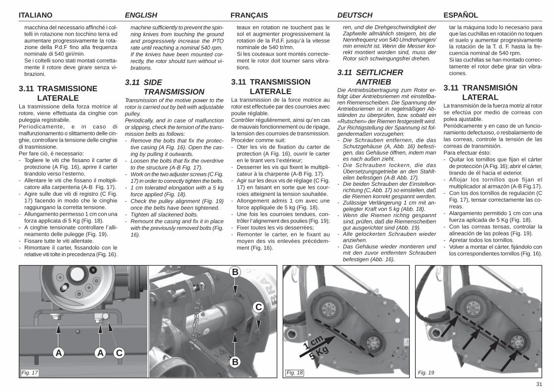
31
ITALIANO ENGLISH FRANÇAIS ESPAÑOLDEUTSCH
macchina del necessario affinché i col-telli in rotazione non tocchino terra edaumentare progressivamente la rota-zione della P.d.F fino alla frequenzanominale di 540 giri/min.Se i coltelli sono stati montati corretta-mente il rotore deve girare senza vi-brazioni.
3.11 TRASMISSIONELATERALE
La trasmissione della forza motrice alrotore, viene effettuata da cinghie conpuleggia registrabile.Periodicamente, e in caso dimalfunzionamento o slittamento delle cin-ghie, controllare la tensione delle cinghiedi trasmissione.Per fare ciò, è necessario:- Togliere le viti che fissano il carter di
protezione (A Fig. 16), aprire il cartertirandolo verso l’esterno.
- Allentare le viti che fissano il moltipli-catore alla carpenteria (A-B Fig. 17).
- Agire sulle due viti di registro (C Fig.17) facendo in modo che le cinghieraggiungano la corretta tensione.
- Allungamento permesso 1 cm con unaforza applicata di 5 Kg (Fig. 18).
- A cinghie tensionate controllare l’alli-neamento delle pulegge (Fig. 19).
- Fissare tutte le viti allentate.- Rimontare il carter, fissandolo con le
relative viti tolte in precedenza (Fig. 16).
machine sufficiently to prevent the spin-ning knives from touching the groundand progressively increase the PTOrate until reaching a nominal 540 rpm.If the knives have been mounted cor-rectly, the rotor should turn without vi-brations.
3.11 SIDETRANSMISSION
Transmission of the motive power to therotor is carried out by belt with adjustablepulley.Periodically, and in case of malfunctionor slipping, check the tension of the trans-mission belts as follows:- Remove the bolts that fix the protec-
tive casing (A Fig. 16). Open the cas-ing by pulling it outwards.
- Loosen the bolts that fix the overdriveto the structure (A-B Fig. 17).
- Work on the two adjuster screws (C Fig.17) in order to correctly tighten the belts.
- 1 cm tolerated elongation with a 5 kgforce applied (Fig. 18).
- Check the pulley alignment (Fig. 19)once the belts have been tightened.
- Tighten all slackened bolts.- Remount the casing and fix it in place
with the previously removed bolts (Fig.16).
ren, und die Drehgeschwindigkeit derZapfwelle allmählich steigern, bis dieNennfrequenz von 540 Umdrehungen/min erreicht ist. Wenn die Messer kor-rekt montiert worden sind, muss derRotor sich schwingungsfrei drehen.
3.11 SEITLICHERANTRIEB
Die Antriebsübertragung zum Rotor er-folgt über Antriebsriemen mit einstellba-ren Riemenscheiben. Die Spannung derAntriebsriemen ist in regelmäßigen Ab-ständen zu überprüfen, bzw. sobald ein«Rutschen» der Riemen festgestellt wird.Zur Richtigstellung der Spannung ist fol-gendermaßen vorzugehen:- Die Schrauben entfernen, die das
Schutzgehäuse (A, Abb. 16) befesti-gen, das Gehäuse öffnen, indem manes nach außen zieht.
- Die Schrauben lockern, die dasÜbersetzungsgetriebe an den Stahlt-eilen befestigen (A-B Abb. 17).
- Die beiden Schrauben der Einstellvor-richtung (C, Abb. 17) so einstellen, daßdie Riemen korrekt gespannt werden.
- Zulässige Verlängerung 1 cm mit an-gelegter Kraft von 5 kg (Abb. 18).
- Wenn die Riemen richtig gespanntsind, prüfen, daß die Riemenscheibengut ausgerichtet sind (Abb. 19).
- Alle gelockerten Schrauben wiederanziehen.
- Das Gehäuse wieder montieren undmit den zuvor entfernten Schraubenbefestigen (Abb. 16).
teaux en rotation ne touchent pas lesol et augmenter progressivement larotation de la P.d.F. jusqu’à la vitessenominale de 540 tr/mn.Si les couteaux sont montés correcte-ment le rotor doit tourner sans vibra-tions.
3.11 TRANSMISSIONLATERALE
La transmission de la force motrice aurotor est effectuée par des courroies avecpoulie réglable.Contrôler régulièrement, ainsi qu’en casde mauvais fonctionnement ou de ripage,la tension des courroies de transmission.Procéder comme suit:- Oter les vis de fixation du carter de
protection (A Fig. 16), ouvrir le carteren le tirant vers l’extérieur;
- Desserrer les vis qui fixent le multipli-cateur à la charpente (A-B Fig. 17).
- Agir sur les deux vis de réglage (C Fig.17) en faisant en sorte que les cour-roies atteignent la tension souhaitée.
- Allongement admis 1 cm avec uneforce appliquée de 5 kg (Fig. 18).
- Une fois les courroies tendues, con-trôler l’alignement des poulies (Fig. 19);
- Fixer toutes les vis desserrées;- Remonter le carter, en le fixant au
moyen des vis enlevées précédem-ment (Fig. 16).
tar la máquina todo lo necesario paraque las cuchillas en rotación no toquenel suelo y aumentar progresivamentela rotación de la T. d. F. hasta la fre-cuencia nominal de 540 rpm.Si las cuchillas se han montado correc-tamente el rotor debe girar sin vibra-ciones.
3.11 TRANSMISIÓNLATERAL
La transmisión de la fuerza motriz al rotorse efectúa por medio de correas conpolea ajustable.Periódicamente y en caso de un funcio-namiento defectuoso, o resbalamiento delas correas, controle la tensión de lascorreas de transmisión.Para efectuar ésto:- Quitar los tornillos que fijan el cárter
de protección (A Fig. 16); abrir el cárter,tirando de él hacia el exterior.
- Aflojar los tornillos que fijan elmultiplicador al armazón (A-B Fig.17).
- Con los dos tornillos de regulación (CFig. 17), tensar correctamente las co-rreas.
- Alargamiento permitido 1 cm con unafuerza aplicada de 5 Kg (Fig. 18).
- Con las correas tensas, controlar laalineación de las poleas (Fig. 19).
- Apretar todos los tornillos.- Volver a montar el cárter, fijándolo con
los correspondientes tornillos (Fig. 16).
Fig. 17
AAB
B
C
C
Fig. 18
1 cm
5 Kg
Fig. 19
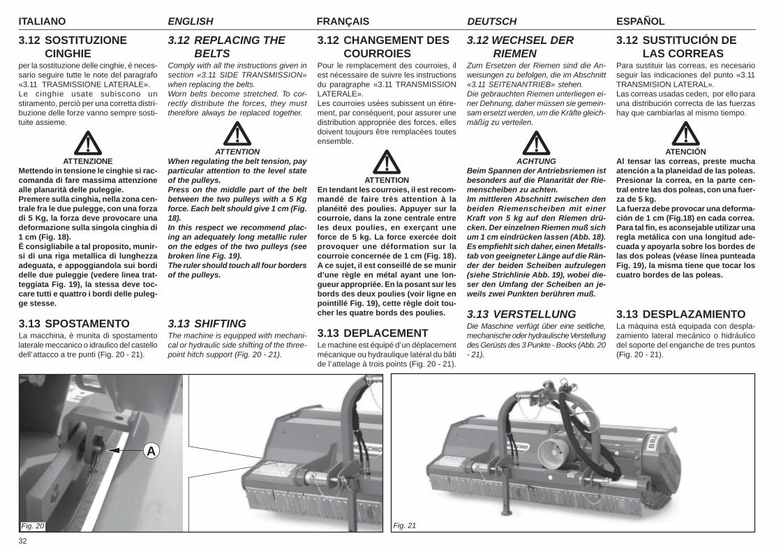
ITALIANO ENGLISH FRANÇAIS ESPAÑOLDEUTSCH
32
3.12 SOSTITUZIONECINGHIE
per la sostituzione delle cinghie, è neces-sario seguire tutte le note del paragrafo«3.11 TRASMISSIONE LATERALE».Le cinghie usate subiscono unstiramento, perciò per una corretta distri-buzione delle forze vanno sempre sosti-tuite assieme.
ATTENZIONEMettendo in tensione le cinghie si rac-comanda di fare massima attenzionealle planarità delle puleggie.Premere sulla cinghia, nella zona cen-trale fra le due pulegge, con una forzadi 5 Kg, la forza deve provocare unadeformazione sulla singola cinghia di1 cm (Fig. 18).È consigliabile a tal proposito, munir-si di una riga metallica di lunghezzaadeguata, e appoggiandola sui bordidelle due puleggie (vedere linea trat-teggiata Fig. 19), la stessa deve toc-care tutti e quattro i bordi delle puleg-ge stesse.
3.13 SPOSTAMENTOLa macchina, è munita di spostamentolaterale meccanico o idraulico del castellodell’attacco a tre punti (Fig. 20 - 21).
3.12 REPLACING THEBELTS
Comply with all the instructions given insection «3.11 SIDE TRANSMISSION»when replacing the belts.Worn belts become stretched. To cor-rectly distribute the forces, they musttherefore always be replaced together.
ATTENTIONWhen regulating the belt tension, payparticular attention to the level stateof the pulleys.Press on the middle part of the beltbetween the two pulleys with a 5 Kgforce. Each belt should give 1 cm (Fig.18).In this respect we recommend plac-ing an adequately long metallic ruleron the edges of the two pulleys (seebroken line Fig. 19).The ruler should touch all four bordersof the pulleys.
3.13 SHIFTINGThe machine is equipped with mechani-cal or hydraulic side shifting of the three-point hitch support (Fig. 20 - 21).
3.12 WECHSEL DERRIEMEN
Zum Ersetzen der Riemen sind die An-weisungen zu befolgen, die im Abschnitt«3.11 SEITENANTRIEB» stehen.Die gebrauchten Riemen unterliegen ei-ner Dehnung, daher müssen sie gemein-sam ersetzt werden, um die Kräfte gleich-mäßig zu verteilen.
ACHTUNGBeim Spannen der Antriebsriemen istbesonders auf die Planarität der Rie-menscheiben zu achten.Im mittleren Abschnitt zwischen denbeiden Riemenscheiben mit einerKraft von 5 kg auf den Riemen drü-cken. Der einzelnen Riemen muß sichum 1 cm eindrücken lassen (Abb. 18).Es empfiehlt sich daher, einen Metalls-tab von geeigneter Länge auf die Rän-der der beiden Scheiben aufzulegen(siehe Strichlinie Abb. 19), wobei die-ser den Umfang der Scheiben an je-weils zwei Punkten berühren muß.
3.13 VERSTELLUNGDie Maschine verfügt über eine seitliche,mechanische oder hydraulische Verstellungdes Gerüsts des 3 Punkte - Bocks (Abb. 20- 21).
3.12 CHANGEMENT DESCOURROIES
Pour le remplacement des courroies, ilest nécessaire de suivre les instructionsdu paragraphe «3.11 TRANSMISSIONLATERALE».Les courroies usées subissent un étire-ment, par conséquent, pour assurer unedistribution appropriée des forces, ellesdoivent toujours être remplacées toutesensemble.
ATTENTIONEn tendant les courroies, il est recom-mandé de faire très attention à laplanéité des poulies. Appuyer sur lacourroie, dans la zone centrale entreles deux poulies, en exerçant uneforce de 5 kg. La force exercée doitprovoquer une déformation sur lacourroie concernée de 1 cm (Fig. 18).A ce sujet, il est conseillé de se munird’une règle en métal ayant une lon-gueur appropriée. En la posant sur lesbords des deux poulies (voir ligne enpointillé Fig. 19), cette règle doit tou-cher les quatre bords des poulies.
3.13 DEPLACEMENTLe machine est équipé d’un déplacementmécanique ou hydraulique latéral du bâtide l’attelage à trois points (Fig. 20 - 21).
3.12 SUSTITUCIÓN DELAS CORREAS
Para sustituir las correas, es necesarioseguir las indicaciones del punto «3.11TRANSMISION LATERAL».Las correas usadas ceden, por ello parauna distribución correcta de las fuerzashay que cambiarlas al mismo tiempo.
ATENCIÓNAl tensar las correas, preste muchaatención a la planeidad de las poleas.Presionar la correa, en la parte cen-tral entre las dos poleas, con una fuer-za de 5 kg.La fuerza debe provocar una deforma-ción de 1 cm (Fig.18) en cada correa.Para tal fin, es aconsejable utilizar unaregla metálica con una longitud ade-cuada y apoyarla sobre los bordes delas dos poleas (véase línea punteadaFig. 19), la misma tiene que tocar loscuatro bordes de las poleas.
3.13 DESPLAZAMIENTOLa máquina está equipada con despla-zamiento lateral mecánico o hidráulicodel soporte del enganche de tres puntos(Fig. 20 - 21).
Fig. 20 Fig. 21
A
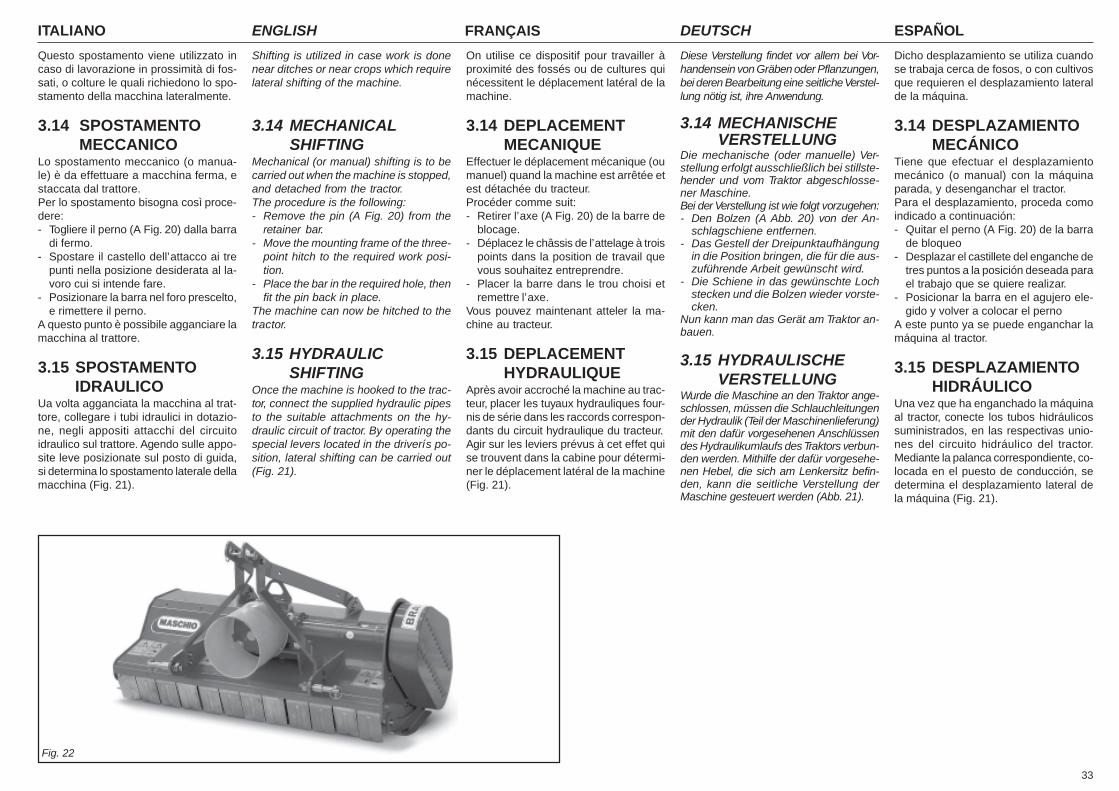
33
ITALIANO ENGLISH FRANÇAIS ESPAÑOLDEUTSCH
Questo spostamento viene utilizzato incaso di lavorazione in prossimità di fos-sati, o colture le quali richiedono lo spo-stamento della macchina lateralmente.
3.14 SPOSTAMENTOMECCANICO
Lo spostamento meccanico (o manua-le) è da effettuare a macchina ferma, estaccata dal trattore.Per lo spostamento bisogna così proce-dere:- Togliere il perno (A Fig. 20) dalla barra
di fermo.- Spostare il castello dell’attacco ai tre
punti nella posizione desiderata al la-voro cui si intende fare.
- Posizionare la barra nel foro prescelto,e rimettere il perno.
A questo punto è possibile agganciare lamacchina al trattore.
3.15 SPOSTAMENTOIDRAULICO
Ua volta agganciata la macchina al trat-tore, collegare i tubi idraulici in dotazio-ne, negli appositi attacchi del circuitoidraulico sul trattore. Agendo sulle appo-site leve posizionate sul posto di guida,si determina lo spostamento laterale dellamacchina (Fig. 21).
Shifting is utilized in case work is donenear ditches or near crops which requirelateral shifting of the machine.
3.14 MECHANICALSHIFTING
Mechanical (or manual) shifting is to becarried out when the machine is stopped,and detached from the tractor.The procedure is the following:- Remove the pin (A Fig. 20) from the
retainer bar.- Move the mounting frame of the three-
point hitch to the required work posi-tion.
- Place the bar in the required hole, thenfit the pin back in place.
The machine can now be hitched to thetractor.
3.15 HYDRAULICSHIFTING
Once the machine is hooked to the trac-tor, connect the supplied hydraulic pipesto the suitable attachments on the hy-draulic circuit of tractor. By operating thespecial levers located in the driverís po-sition, lateral shifting can be carried out(Fig. 21).
Diese Verstellung findet vor allem bei Vor-handensein von Gräben oder Pflanzungen,bei deren Bearbeitung eine seitliche Verstel-lung nötig ist, ihre Anwendung.
3.14 MECHANISCHEVERSTELLUNG
Die mechanische (oder manuelle) Ver-stellung erfolgt ausschließlich bei stillste-hender und vom Traktor abgeschlosse-ner Maschine.Bei der Verstellung ist wie folgt vorzugehen:- Den Bolzen (A Abb. 20) von der An-
schlagschiene entfernen.- Das Gestell der Dreipunktaufhängung
in die Position bringen, die für die aus-zuführende Arbeit gewünscht wird.
- Die Schiene in das gewünschte Lochstecken und die Bolzen wieder vorste-cken.
Nun kann man das Gerät am Traktor an-bauen.
3.15 HYDRAULISCHEVERSTELLUNG
Wurde die Maschine an den Traktor ange-schlossen, müssen die Schlauchleitungender Hydraulik (Teil der Maschinenlieferung)mit den dafür vorgesehenen Anschlüssendes Hydraulikumlaufs des Traktors verbun-den werden. Mithilfe der dafür vorgesehe-nen Hebel, die sich am Lenkersitz befin-den, kann die seitliche Verstellung derMaschine gesteuert werden (Abb. 21).
On utilise ce dispositif pour travailler àproximité des fossés ou de cultures quinécessitent le déplacement latéral de lamachine.
3.14 DEPLACEMENTMECANIQUE
Effectuer le déplacement mécanique (oumanuel) quand la machine est arrêtée etest détachée du tracteur.Procéder comme suit:- Retirer l’axe (A Fig. 20) de la barre de
blocage.- Déplacez le châssis de l’attelage à trois
points dans la position de travail quevous souhaitez entreprendre.
- Placer la barre dans le trou choisi etremettre l’axe.
Vous pouvez maintenant atteler la ma-chine au tracteur.
3.15 DEPLACEMENTHYDRAULIQUE
Après avoir accroché la machine au trac-teur, placer les tuyaux hydrauliques four-nis de série dans les raccords correspon-dants du circuit hydraulique du tracteur.Agir sur les leviers prévus à cet effet quise trouvent dans la cabine pour détermi-ner le déplacement latéral de la machine(Fig. 21).
Dicho desplazamiento se utiliza cuandose trabaja cerca de fosos, o con cultivosque requieren el desplazamiento lateralde la máquina.
3.14 DESPLAZAMIENTOMECÁNICO
Tiene que efectuar el desplazamientomecánico (o manual) con la máquinaparada, y desenganchar el tractor.Para el desplazamiento, proceda comoindicado a continuación:- Quitar el perno (A Fig. 20) de la barra
de bloqueo- Desplazar el castillete del enganche de
tres puntos a la posición deseada parael trabajo que se quiere realizar.
- Posicionar la barra en el agujero ele-gido y volver a colocar el perno
A este punto ya se puede enganchar lamáquina al tractor.
3.15 DESPLAZAMIENTOHIDRÁULICO
Una vez que ha enganchado la máquinaal tractor, conecte los tubos hidráulicossuministrados, en las respectivas unio-nes del circuito hidráulico del tractor.Mediante la palanca correspondiente, co-locada en el puesto de conducción, sedetermina el desplazamiento lateral dela máquina (Fig. 21).
Fig. 22
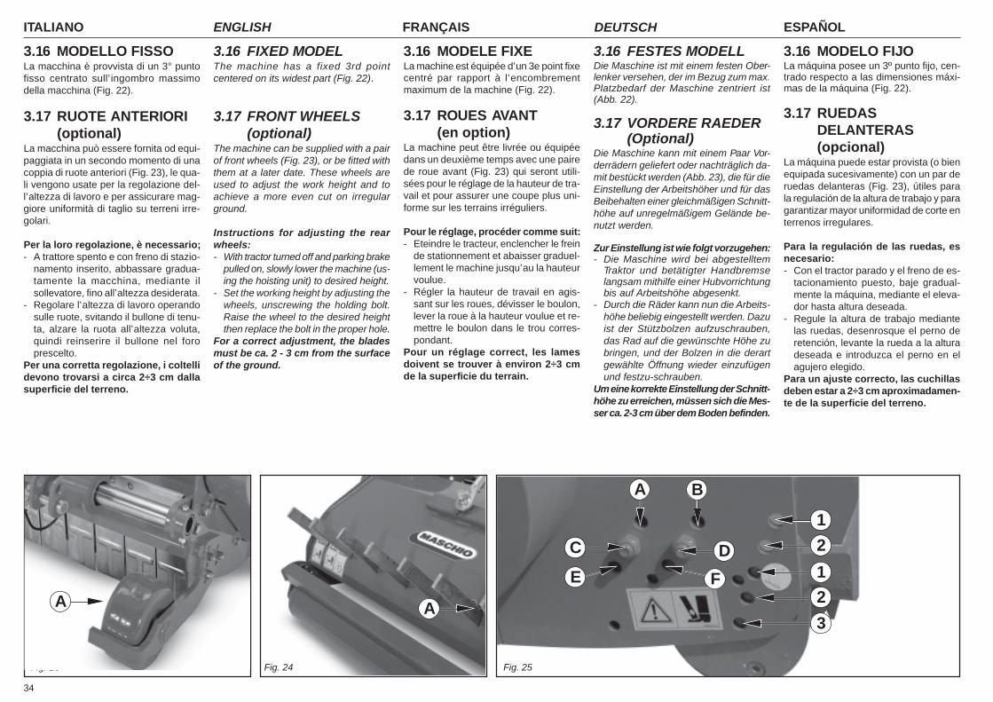
ITALIANO ENGLISH FRANÇAIS ESPAÑOLDEUTSCH
34
3.16 MODELLO FISSOLa macchina è provvista di un 3° puntofisso centrato sull’ingombro massimodella macchina (Fig. 22).
3.17 RUOTE ANTERIORI(optional)
La macchina può essere fornita od equi-paggiata in un secondo momento di unacoppia di ruote anteriori (Fig. 23), le qua-li vengono usate per la regolazione del-l’altezza di lavoro e per assicurare mag-giore uniformità di taglio su terreni irre-golari.
Per la loro regolazione, è necessario;- A trattore spento e con freno di stazio-
namento inserito, abbassare gradua-tamente la macchina, mediante ilsollevatore, fino all’altezza desiderata.
- Regolare l’altezza di lavoro operandosulle ruote, svitando il bullone di tenu-ta, alzare la ruota all’altezza voluta,quindi reinserire il bullone nel foroprescelto.
Per una corretta regolazione, i coltellidevono trovarsi a circa 2÷3 cm dallasuperficie del terreno.
3.16 FIXED MODELThe machine has a fixed 3rd pointcentered on its widest part (Fig. 22).
3.17 FRONT WHEELS(optional)
The machine can be supplied with a pairof front wheels (Fig. 23), or be fitted withthem at a later date. These wheels areused to adjust the work height and toachieve a more even cut on irregularground.
Instructions for adjusting the rearwheels:- With tractor turned off and parking brake
pulled on, slowly lower the machine (us-ing the hoisting unit) to desired height.
- Set the working height by adjusting thewheels, unscrewing the holding bolt.Raise the wheel to the desired heightthen replace the bolt in the proper hole.
For a correct adjustment, the bladesmust be ca. 2 - 3 cm from the surfaceof the ground.
3.16 MODELO FIJOLa máquina posee un 3º punto fijo, cen-trado respecto a las dimensiones máxi-mas de la máquina (Fig. 22).
3.17 RUEDASDELANTERAS(opcional)
La máquina puede estar provista (o bienequipada sucesivamente) con un par deruedas delanteras (Fig. 23), útiles parala regulación de la altura de trabajo y paragarantizar mayor uniformidad de corte enterrenos irregulares.
Para la regulación de las ruedas, esnecesario:- Con el tractor parado y el freno de es-
tacionamiento puesto, baje gradual-mente la máquina, mediante el eleva-dor hasta altura deseada.
- Regule la altura de trabajo mediantelas ruedas, desenrosque el perno deretención, levante la rueda a la alturadeseada e introduzca el perno en elagujero elegido.
Para un ajuste correcto, las cuchillasdeben estar a 2÷3 cm aproximadamen-te de la superficie del terreno.
3.16 MODELE FIXELa machine est équipée d’un 3e point fixecentré par rapport à l’encombrementmaximum de la machine (Fig. 22).
3.17 ROUES AVANT(en option)
La machine peut être livrée ou équipéedans un deuxième temps avec une pairede roue avant (Fig. 23) qui seront utili-sées pour le réglage de la hauteur de tra-vail et pour assurer une coupe plus uni-forme sur les terrains irréguliers.
Pour le réglage, procéder comme suit:- Eteindre le tracteur, enclencher le frein
de stationnement et abaisser graduel-lement le machine jusqu’au la hauteurvoulue.
- Régler la hauteur de travail en agis-sant sur les roues, dévisser le boulon,lever la roue à la hauteur voulue et re-mettre le boulon dans le trou corres-pondant.
Pour un réglage correct, les lamesdoivent se trouver à environ 2÷3 cmde la superficie du terrain.
3.16 FESTES MODELLDie Maschine ist mit einem festen Ober-lenker versehen, der im Bezug zum max.Platzbedarf der Maschine zentriert ist(Abb. 22).
3.17 VORDERE RAEDER(Optional)
Die Maschine kann mit einem Paar Vor-derrädern geliefert oder nachträglich da-mit bestückt werden (Abb. 23), die für dieEinstellung der Arbeitshöher und für dasBeibehalten einer gleichmäßigen Schnitt-höhe auf unregelmäßigem Gelände be-nutzt werden.
Zur Einstellung ist wie folgt vorzugehen:- Die Maschine wird bei abgestelltem
Traktor und betätigter Handbremselangsam mithilfe einer Hubvorrichtungbis auf Arbeitshöhe abgesenkt.
- Durch die Räder kann nun die Arbeits-höhe beliebig eingestellt werden. Dazuist der Stützbolzen aufzuschrauben,das Rad auf die gewünschte Höhe zubringen, und der Bolzen in die derartgewählte Öffnung wieder einzufügenund festzu-schrauben.
Um eine korrekte Einstellung der Schnitt-höhe zu erreichen, müssen sich die Mes-ser ca. 2-3 cm über dem Boden befinden.
Fig. 23 Fig. 24
A
Fig. 25
A
D
A B
F
C
E
1
2
1
3
2
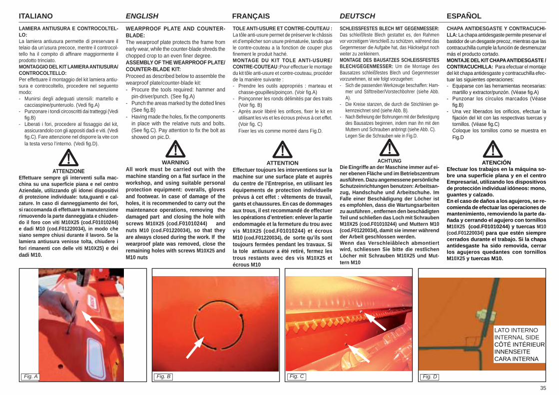
35
ITALIANO ENGLISH FRANÇAIS ESPAÑOLDEUTSCHWEARPROOF PLATE AND COUNTER-BLADE: The wearproof plate protects the frame from early wear, while the counter-blade shreds the chopped crop to an even fi ner degree.ASSEMBLY OF THE WEARPROOF PLATE/COUNTER-BLADE KIT:Proceed as described below to assemble the wearproof plate/counter-blade kit:- Procure the tools required: hammer and
pin-driver/punch. (See fi g.A)- Punch the areas marked by the dotted lines
(See fi g.B)- Having made the holes, fi x the components
in place with the relative nuts and bolts. (See fi g.C). Pay attention to fi x the bolt as showed on pic.D.
WARNINGAll work must be carried out with the machine standing on a fl at surface in the workshop, and using suitable personal protection equipment: overalls, gloves and footwear. In case of damage of the holes, it is recommended to carry out the maintenance operations, removing the damaged part and closing the hole with screws M10X25 (cod.F01010244) and nuts M10 (cod.F01220034), so that they are always closed during the work. If the wearproof plate was removed, close the remaining holes with screws M10X25 and M10 nuts
SCHLEISSFESTES BLECH MIT GEGENMESSER: Das schleißfeste Blech gestattet es, den Rahmen vor vorzeitigem Verschleiß zu schützen, während das Gegenmesser die Aufgabe hat, das Häckselgut noch weiter zu zerkleinern.MONTAGE DES BAUSATZES SCHLEISSFESTES BLECH/GEGENMESSER: Um die Montage des Bausatzes schleißfestes Blech und Gegenmesser vorzunehmen, ist wie folgt vorzugehen:- Sich die passenden Werkzeuge beschaffen: Ham-
mer und Stifttreiber/Vorstechbohrer (siehe Abb. A).
- Die Kreise stanzen, die durch die Strichlinien ge-kennzeichnet sind (siehe Abb. B).
- Nach Befreiung der Bohrungen mit der Befestigung des Bausatzes beginnen, indem man ihn mit den Muttern und Schrauben anbringt (siehe Abb. C).
Legen Sie die Schrauben wie in Fig.D.
ACHTUNGDie Eingriffe an der Maschine immer auf ei-ner ebenen Fläche und im Betriebszentrum ausführen. Dazu angemessene persönliche Schutzeinrichtungen benutzen: Arbeitsan-zug, Handschuhe und Arbeitschuhe. Im Falle einer Beschädigung der Löcher ist es empfohlen, dass die Wartungsarbeiten zu ausführen , entfernen den beschädigten Teil und schließen das Loch mit Schrauben M10X25 (cod.F01010244) und Muttern M10 (cod.F01220034), damit sie immer während der Arbeit geschlossen werden.Wenn das Verschleiâblech abmontiert wird, schliessen Sie bitte die restlichen Löcher mit Schrauben M10X25 und Mut-tern M10
TOLE ANTI-USURE ET CONTRE-COUTEAU : La tôle anti-usure permet de préserver le châssis et d’empêcher son usure prématurée, tandis que le contre-couteau a la fonction de couper plus fi nement le produit haché.MONTAGE DU KIT TOLE ANTI-USURE/CONTRE-COUTEAU :Pour effectuer le montage du kit tôle anti-usure et contre-couteau, procéder de la manière suivante :- Prendre les outils appropriés : marteau et
chasse-goupilles/poinçon. (Voir fi g.A)- Poinçonner les ronds délimités par des traits
(Voir fi g. B)- Après avoir libéré les orifi ces, fi xer le kit en
utilisant les vis et les écrous prévus à cet effet. (Voir fi g. C)
Fixer les vis comme montré dans Fig.D.
ATTENTIONEffectuer toujours les interventions sur la machine sur une surface plate et auprès du centre de l’Entreprise, en utilisant les équipements de protection individuelle prévus à cet effet : vêtements de travail, gants et chaussures. En cas de dommages aux trous, il est recommandé de effectuer les opérations d’entretien: enlever la partie endommagée et la fermeture du trou avec vis M10X25 (cod.F01010244) et écrous M10 (cod.F01220034), de sorte qu’ils sont toujours fermées pendant les travaux. Si la tole antiusure a été retiré, fermez les trous restants avec des vis M10X25 et écrous M10
Fig. CFig. A Fig. B Fig. D
LAMIERA ANTIUSURA E CONTROCOLTEL-LO:La lamiera antiusura permette di preservare il telaio da un’usura precoce, mentre il controcol-tello ha il compito di affi nare maggiormente il prodotto trinciato.MONTAGGIO DEL KIT LAMIERA ANTIUSURA/CONTROCOLTELLO:Per effettuare il montaggio del kit lamiera antiu-sura e controcoltello, procedere nel seguento modo:- Munirsi degli adeguati utensili: martello e
cacciaspine/punteruolo. (Vedi fi g.A)- Punzonare i tondi circoscritti dai tratteggi (Vedi
fi g.B)- Liberati i fori, procedere al fi ssaggio del kit,
assicurandolo con gli appositi dadi e viti. (Vedi fi g.C). Fare attenzione nel disporre la vite con la testa verso l’interno. (Vedi fi g.D).
ATTENZIONEEffettuare sempre gli interventi sulla mac-china su una superfi cie piana e nel centro Aziendale, utilizzando gli idonei dispositivi di protezione individuale: tuta,guanti e cal-zature. In caso di danneggiamento dei fori, si raccomanda di effettuare la manutenzione rimuovendo la parte danneggiata e chiuden-do il foro con viti M10X25 (cod.F01010244) e dadi M10 (cod.F01220034), in modo che siano sempre chiusi durante il lavoro. Se la lamiera antiusura venisse tolta, chiudere i fori rimanenti con delle viti M10X25) e dei dadi M10.
CHAPA ANTIDESGASTE Y CONTRACUCHI-LLA: La chapa antidesgaste permite preservar el bastidor de un desgaste precoz, mientras que las contracuchilla cumple la función de desmenuzar más el producto cortado.MONTAJE DEL KIT CHAPA ANTIDESGASTE /CONTRACUCHILLA: Para efectuar el montaje del kit chapa antidesgaste y contracuchilla efec-tuar las siguientes operaciones:- Equiparse con las herramientas necesarias:
martillo y extractor/punzón. (Véase fi g.A)- Punzonar los círculos marcados (Véase
fi g.B)- Una vez liberados los orifi cios, efectuar la
fi jación del kit con las respectivas tuercas y tornillos. (Véase fi g.C)
Coloque los tornillos como se muestra en Fig.D
ATENCIÓN
Efectuar los trabajos en la máquina so-bre una superfi cie plana y en el centro Empresarial, utilizando los dispositivos de protección individual idóneos: mono, guantes y calzado.En el caso de daños a los agujeros, se re-comienda de efectuar las operaciones de mantenimiento, removiendo la parte da-ñada y cerrando el agujero con tornillos M10X25 (cod.F01010244) y tuercas M10 (cod.F01220034) para que estén siempre cerrados durante el trabajo. Si la chapa antidesgaste ha sido removida, cerrar los agujeros quedantes con tornillos M10X25 y tuercas M10.
LATO INTERNOINTERNAL SIDECÔTÉ INTÉRIEURINNENSEITECARA INTERNA
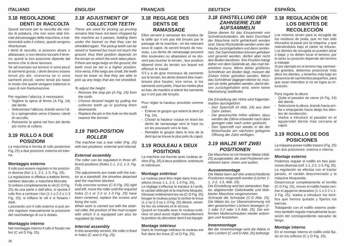
ITALIANO ENGLISH FRANÇAIS ESPAÑOLDEUTSCH
36
3.18 EINSTELLUNG DERZAHNSERIE ZUMAUFSAMMELN
Diese dienen für das Einsammeln vonSchnittrückständen, die beim Durchlaufder Maschine nicht gehäckselt wordensind. Diese Rückstände werden unter derHaube zurückgehalten und dann zerklei-nert. Die Sammelzinken können gehobenund gesenkt werden, dürfen aber nichtden Boden berühren. Ihre Position hängtdaher von dem Gelände ab, das man be-arbeiten muss. Wenn daher größeresSchnittholz am Boden liegt, müssen dieZinken höher gehalten werden. Wenndas Schnittholz dagegen kleiner ist, müs-sen sie tiefer gehalten werden, damit die-ses zurückgehalten wird, wenn keineHäckselung stattfindet.
Die Einstellung der Höhe wird folgender-maßen durchgeführt:- Den Sperrstift (A Abb. 24) aus dem
Zahn ziehen.- Die gewünschte Höhe wählen: dazu
werden die Zähne entweder nach obengezogen oder nach unten gedrückt.
- Den Sperrstift nun wieder in die derMotorhaube am nächsten gelegeneÖffnung der Zahn einfügen.
3.19 WALZE MIT ZWEIPOSITIONEN
Die Maschine ist mit hinterer Walze (Abb.25) ausgestattet, die zwei Positionen ein-nehmen kann: innen und außen.
AussenmontageDie Walze kann auf drei unterschiedlichePositionen eingestellt werden (Löcher 1-1, 2-2, 1-3, Abb. 25).Die Einstellung wird bei stehendem Trak-tor, abgetrennter Gelenkwelle und blok-kierter Maschine vorgenommen.Schraubt die Schraube (C-D Abb. 25).Die Walze bis zur Übereinstimmung mitden gewünschten Löchern bewegen (1-1 oder 2-2 oder 1-3 Abb. 25). Die ent-fernten Mutterschrauben wieder anbrin-gen und festziehen.
InnenmontageBei der Innenmontage wird die Walze inden Löchern (C und D Abb. 25) befestigt.
3.18 REGLAGE DESDENTS DERAMASSAGE
Elles servent à ramasser les résidus dela taille qui n’ont pas été broyés par lepassage de la machine ; en les retenantsous le capot, ils seront broyés de nou-veau. Les dents de ramassage peuventêtre soulevées ou abaissées et ne doi-vent pas toucher le terrain ; leur positiondépend donc du terrain sur lequel esteffectué le travail.S’il y a de gros morceaux de sarmentssur le terrain, les dents doivent être main-tenues plus hautes; vice versa, si lessarments sont petits, il faut les mettre plusen bas, de manière à retenir les sarmentsqui n’ont pas été broyés.
Pour régler la hauteur, procéder commesuit:- Enlever le goujon qui retient la dent (A
Fig. 24).- Choisir la hauteur voulue en tirant les
dents de ramassage vers le haut ouen les poussant vers le bas.
- Remettre le goujon dans le trou de ladent qui se trouve le plus près du capot.
3.19 ROULEAU A DEUXPOSITIONS
La machine est fournie avec rouleau ar-rière (Fig. 25) à deux positions: extérieureet intérieure.
Montage extérieurLe rouleau peut être réglé dans trois po-sitions (trous 1-1, 2-2, 1-3 Fig. 25).Le réglage s’effectue le tracteur à l’arrêt,le cardan débrayé et la machine bloquée.Dévisser entièrement les vis (C-D Fig. 25)bouger le rouleau jusqu’à centrer le trous(1-1 ou 2-2 ou 1-3 Fig. 25) désiré, remet-tre les vis enlevés et le écrous.Quand on travaille avec le rouleau exté-rieur on peut aussi régler manuellementla position du décrottoir dont il est équipé.
Montage intérieurDans le montage intérieur le rouleau estfixé dans les trous (C et D Fig. 25).
3.18 REGULACIÓN DELOS DIENTES DERECOLECCIÓN
Los mismos sirven para la recogida delos residuos de poda, que no han sidotriturados al pasar por la máquina, y quereteniéndolos bajo el cárter se trituran.Los dientes de recogida se pueden alzaro bajar, y no deben tocar el terreno; porlo tanto su posición depende del terrenoa trabajar.Si por ejemplo en el terreno hay sarmien-tos grandes, debemos posicionar másaltos los dientes, y tenerlos más bajo enpresencia de sarmientos pequeños, paraque sean retenidos si no se logra su tri-turación.
Para regular la altura:- Quite el pasador de cierre (A Fig. 24)
del diente.- Seleccione la altura, tirando hacia arri-
ba o empujando hacia abajo los dien-tes de recolección.
- Vuelva a introducir el pasador en elagujerodel diente más cercana alcapot.
3.19 RODILLO DE DOSPOSICIONES
La máquina posee rodillo trasero (Fig. 25)con dos posiciones: externa e interna.
Montaje externoPodemos regular el rodillo en tres posi-ciones diversas (orif. 1-1, 2-2, 1-3, Fig. 25).La regulación se efectúa con el tractorparado, el cardán desconectado y lamáquina bloqueada.Desenroscar completamente el tornillo(C-D Fig. 25), mover el rodillo hasta cen-trar el agujeros deseados (1-1 o 2-2 o 1-3 Fig. 25). Vuelva a introducir los torni-llos que hemos quitado y fijarlos lostuercas.Trabajando con el rodillo externo pode-mos también regular manualmente la po-sición del correspondiente rascador defango.
Montaje internoEn el montaje interno el rodillo está fija-do en los orificios (C y D Fig. 25).
3.18 ADJUSTMENT OFCOLLECTOR TEETH
These are used for picking up pruningremains that have not been chopped bythe machine as it passes, holding themunder the bonnet so that they can beshredded again. The pickup teeth can beraised or lowered but must not touch theground, thus their position depends onthe terrain on which the work takes place.If there are large twigs on the ground, theteeth must be set in a higher position.Vice versa, if the twigs are small, the teethmust be lower so that they are able topick up any twigs that are not shredded.
To adjust the height:- Remove the stop pin (A Fig. 24) from
the tooth.- Choose desired height by pulling the
collector teeth up or pushing themdownwards.
- Replace the pin in the hole on the toothnearest the bonnet.
3.19 TWO-POSITIONROLLER
The machine has a rear roller (Fig. 25)with two positions: external and internal.
External assemblyThe roller can be regulated in three dif-ferent positions (holes 1-1, 2-2, 1-3, Fig.25).The adjustments are made with the trac-tor at a standstill, the driveline detachedand the machine blocked.Fully unscrew screws (C-D Fig. 25) rightand left, move the roller until the requiredholes (1-1 or 2-2 or 1-3 Fig. 25) havebeen centered, replace the screws andfixing the nuts.When work is carried out with the exter-nal roller, the position of the mud scraperwith which it is equipped can also beregulated by hand.
Internal assemblyIn this assembly version, the roller is fixedin holes (C and D Fig. 25).
3.18 REGOLAZIONEDENTI DI RACCOLTA
Questi servono per la raccolta dei resi-dui di potatura, che non sono stati trin-ciati dal passaggio della macchina, e trat-tenendoli sotto il cofano, questi vengonorifrantumati.I denti di raccolta, si possono alzare oabbassare, e non devono toccare il terre-no; quindi la loro posizione dipende dalterreno che si deve lavorare.Se ad esempio sul terreno vi sono pezzidi sarmenti grossi, i denti devono esseretenuti più alti, viceversa se vi sonosarmenti piccoli, vanno tenuti più bassiin modo che questi vengano trattenuti incaso di non frantumazione.
Per regolare l’altezza, è necessario:- Togliere la spina di fermo (A Fig. 24)
dal dente.- Selezionare l’altezza, tirando verso l’al-
to o spingendolo verso il basso i dentidi raccolta.
- Reinserire la spina nel foro del dentepiù vicino al cofano.
3.19 RULLO A DUEPOSIZIONI
La macchina è fornita di rullo posterioreFig. 25) a due posizioni: esterna ed inter-na.
Montaggio esternoIl rullo può essere regolato in tre posizio-ni diverse (fori 1-1, 2-2, 1-3, Fig. 25).La regolazione si effettua a trattore fermo,cardano staccato, e macchina bloccata.Si svitano completamente le viti (C-D Fig.25) da una parte e dall’altra; si sposta ilrullo fino a centrare i fori (1-1 o 2-2 o 1-3Fig. 25); si infilano le viti e si fissano idadi.Lavorando con il rullo esterno si può an-che regolare manualmente la posizionedel raschiafango di cui è dotato.
Montaggio internoNel montaggio interno il rullo è fissato neifori (C ed D Fig. 25).
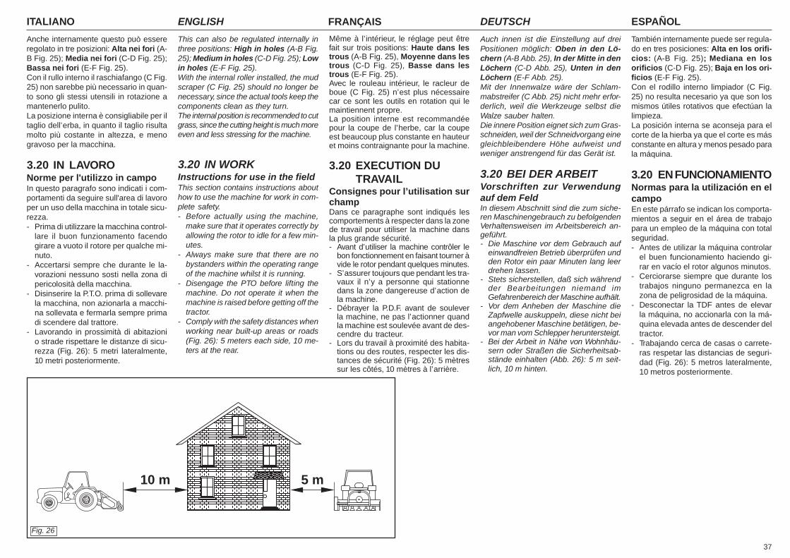
37
ITALIANO ENGLISH FRANÇAIS ESPAÑOLDEUTSCH
Anche internamente questo può essereregolato in tre posizioni: Alta nei fori (A-B Fig. 25); Media nei fori (C-D Fig. 25);Bassa nei fori (E-F Fig. 25).Con il rullo interno il raschiafango (C Fig.25) non sarebbe più necessario in quan-to sono gli stessi utensili in rotazione amantenerlo pulito.La posizione interna è consigliabile per iltaglio dell’erba, in quanto il taglio risultamolto più costante in altezza, e menogravoso per la macchina.
3.20 IN LAVORONorme per l'utilizzo in campoIn questo paragrafo sono indicati i com-portamenti da seguire sull'area di lavoroper un uso della macchina in totale sicu-rezza.- Prima di utilizzare la macchina control-
lare il buon funzionamento facendogirare a vuoto il rotore per qualche mi-nuto.
- Accertarsi sempre che durante le la-vorazioni nessuno sosti nella zona dipericolosità della macchina.
- Disinserire la P.T.O. prima di sollevarela macchina, non azionarla a macchi-na sollevata e fermarla sempre primadi scendere dal trattore.
- Lavorando in prossimità di abitazionio strade rispettare le distanze di sicu-rezza (Fig. 26): 5 metri lateralmente,10 metri posteriormente.
This can also be regulated internally inthree positions: High in holes (A-B Fig.25); Medium in holes (C-D Fig. 25); Lowin holes (E-F Fig. 25).With the internal roller installed, the mudscraper (C Fig. 25) should no longer benecessary, since the actual tools keep thecomponents clean as they turn.The internal position is recommended to cutgrass, since the cutting height is much moreeven and less stressing for the machine.
3.20 IN WORKInstructions for use in the fieldThis section contains instructions abouthow to use the machine for work in com-plete safety.- Before actually using the machine,
make sure that it operates correctly byallowing the rotor to idle for a few min-utes.
- Always make sure that there are nobystanders within the operating rangeof the machine whilst it is running.
- Disengage the PTO before lifting themachine. Do not operate it when themachine is raised before getting off thetractor.
- Comply with the safety distances whenworking near built-up areas or roads(Fig. 26): 5 meters each side, 10 me-ters at the rear.
Auch innen ist die Einstellung auf dreiPositionen möglich: Oben in den Lö-chern (A-B Abb. 25), In der Mitte in denLöchern (C-D Abb. 25), Unten in denLöchern (E-F Abb. 25).Mit der Innenwalze wäre der Schlam-mabstreifer (C Abb. 25) nicht mehr erfor-derlich, weil die Werkzeuge selbst dieWalze sauber halten.Die innere Position eignet sich zum Gras-schneiden, weil der Schneidvorgang einegleichbleibendere Höhe aufweist undweniger anstrengend für das Gerät ist.
3.20 BEI DER ARBEITVorschriften zur Verwendungauf dem FeldIn diesem Abschnitt sind die zum siche-ren Maschinengebrauch zu befolgendenVerhaltensweisen im Arbeitsbereich an-geführt.- Die Maschine vor dem Gebrauch auf
einwandfreien Betrieb überprüfen undden Rotor ein paar Minuten lang leerdrehen lassen.
- Stets sicherstellen, daß sich währendder Bearbeitungen niemand imGefahrenbereich der Maschine aufhält.
- Vor dem Anheben der Maschine dieZapfwelle auskuppeln, diese nicht beiangehobener Maschine betätigen, be-vor man vom Schlepper heruntersteigt.
- Bei der Arbeit in Nähe von Wohnhäu-sern oder Straßen die Sicherheitsab-stände einhalten (Abb. 26): 5 m seit-lich, 10 m hinten.
Même à l’intérieur, le réglage peut êtrefait sur trois positions: Haute dans lestrous (A-B Fig. 25), Moyenne dans lestrous (C-D Fig. 25), Basse dans lestrous (E-F Fig. 25).Avec le rouleau intérieur, le racleur deboue (C Fig. 25) n’est plus nécessairecar ce sont les outils en rotation qui lemaintiennent propre.La position interne est recommandéepour la coupe de l’herbe, car la coupeest beaucoup plus constante en hauteuret moins contraignante pour la machine.
3.20 EXECUTION DUTRAVAIL
Consignes pour l’utilisation surchampDans ce paragraphe sont indiqués lescomportements à respecter dans la zonede travail pour utiliser la machine dansla plus grande sécurité.- Avant d’utiliser la machine contrôler le
bon fonctionnement en faisant tourner àvide le rotor pendant quelques minutes.
- S’assurer toujours que pendant les tra-vaux il n’y a personne qui stationnedans la zone dangereuse d’action dela machine.
- Débrayer la P.D.F. avant de souleverla machine, ne pas l’actionner quandla machine est soulevée avant de des-cendre du tracteur.
- Lors du travail à proximité des habita-tions ou des routes, respecter les dis-tances de sécurité (Fig. 26): 5 mètressur les côtés, 10 mètres à l’arrière.
También internamente puede ser regula-do en tres posiciones: Alta en los orifi-cios: (A-B Fig. 25); Mediana en losorificios (C-D Fig. 25); Baja en los ori-ficios (E-F Fig. 25).Con el rodillo interno limpiador (C Fig.25) no resulta necesario ya que son losmismos útiles rotativos que efectúan lalimpieza.La posición interna se aconseja para elcorte de la hierba ya que el corte es másconstante en altura y menos pesado parala máquina.
3.20 EN FUNCIONAMIENTONormas para la utilización en elcampoEn este párrafo se indican los comporta-mientos a seguir en el área de trabajopara un empleo de la máquina con totalseguridad.- Antes de utilizar la máquina controlar
el buen funcionamiento haciendo gi-rar en vacío el rotor algunos minutos.
- Cerciorarse siempre que durante lostrabajos ninguno permanezca en lazona de peligrosidad de la máquina.
- Desconectar la TDF antes de elevarla máquina, no accionarla con la má-quina elevada antes de descender deltractor.
- Trabajando cerca de casas o carrete-ras respetar las distancias de seguri-dad (Fig. 26): 5 metros lateralmente,10 metros posteriormente.
Fig. 26
10 m 5 m
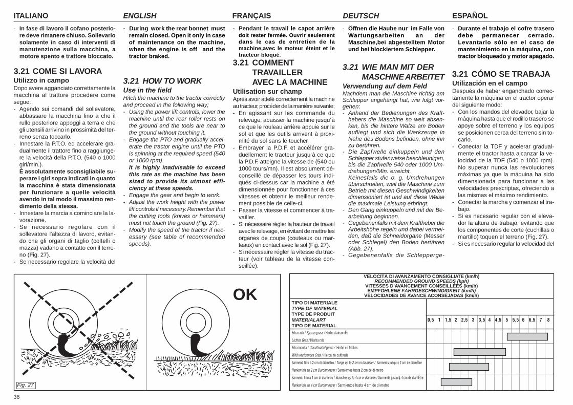
ITALIANO ENGLISH FRANÇAIS ESPAÑOLDEUTSCH
38
- In fase di lavoro il cofano posterio-re deve rimanere chiuso. Sollevarlosolamente in caso di interventi dimanutenzione sulla macchina, amotore spento e trattore bloccato.
3.21 COME SI LAVORAUtilizzo in campoDopo avere agganciato correttamente lamacchina al trattore procedere comesegue:- Agendo sui comandi del sollevatore,
abbassare la macchina fino a che ilrullo posteriore appoggi a terra e chegli utensili arrivino in prossimità del ter-reno senza toccarlo.
- Innestare la P.T.O. ed accelerare gra-dualmente il trattore fino a raggiunge-re la velocità della P.T.O. (540 o 1000giri/min.).È assolutamente sconsigliabile su-perare i giri sopra indicati in quantola macchina è stata dimensionataper funzionare a quelle velocitàavendo in tal modo il massimo ren-dimento della stessa.
- Innestare la marcia a cominciare la la-vorazione.
- Se necessario regolare con ilsollevatore l'altezza di lavoro, evitan-do che gli organi di taglio (coltelli omazza) vadano a contatto con il terre-no (Fig. 27).
- Se necessario regolare la velocità del
- During work the rear bonnet mustremain closed. Open it only in caseof maintenance on the machine,when the engine is off and thetractor braked.
3.21 HOW TO WORKUse in the fieldHitch the machine to the tractor correctlyand proceed in the following way;- Using the power lift controls, lower the
machine until the rear roller rests onthe ground and the tools are near tothe ground without touching it.
- Engage the PTO and gradually accel-erate the tractor engine until the PTOis spinning at the required speed (540or 1000 rpm).It is highly inadvisable to exceedthis rate as the machine has beensized to provide its utmost effi-ciency at these speeds.
- Engage the gear and begin to work.- Adjust the work height with the power
lift controls if necessary. Remember thatthe cutting tools (knives or hammers)must not touch the ground (Fig. 27).
- Modify the speed of the tractor if nec-essary (see table of recommendedspeeds).
- Öffnen die Haube nur im Falle vonWartungsarbeiten an derMaschine,bei abgestelltem Motorund bei blockiertem Schlepper.
3.21 WIE MAN MIT DERMASCHINE ARBEITET
Verwendung auf dem FeldNachdem man die Maschine richtig amSchlepper angehängt hat, wie folgt vor-gehen:- Anhand der Bedienungen des Kraft-
hebers die Maschine so weit absen-ken, bis die hintere Walze am Bodenaufliegt und sich die Werkzeuge inNähe des Bodens befinden, ohne ihnzu berühren.
- Die Zapfwelle einkuppeln und denSchlepper stufenweise beschleunigen,bis die Zapfwelle 540 oder 1000 Um-drehungen/Min. erreicht.Keinesfalls die o. g. Umdrehungenüberschreiten, weil die Maschine zumBetrieb mit diesen Geschwindigkeitendimensioniert ist und auf diese Weisedie maximale Leistung erbringt.
- Den Gang einkuppeln und mit der Be-arbeitung beginnen.
- Gegebenenfalls mit dem Kraftheber dieArbeitshöhe regeln und dabei vermei-den, daß die Schneidorgane (Messeroder Schlegel) den Boden berühren(Abb. 27).
- Gegebenenfalls die Schlepperge-
- Pendant le travail le capot arrièredoit rester fermée. Ouvrir seulementdans le cas de entretien de lamachine,avec le moteur éteint et letracteur bloqué.
3.21 COMMENTTRAVAILLERAVEC LA MACHINE
Utilisation sur champAprès avoir attelé correctement la machineau tracteur, procéder de la manière suivante;- En agissant sur les commande du
relevage, abaisser la machine jusqu’àce que le rouleau arrière appuie sur lesol et que les outils arrivent à proxi-mité du sol sans le toucher.
- Embrayer la P.D.F. et accélérer gra-duellement le tracteur jusqu’à ce quela P.D.F. atteigne la vitesse de (540 ou1000 tours/mn). Il est absolument dé-conseillé de dépasser les tours indi-qués ci-dessus car la machine a étédimensionnée pour fonctionner à cesvitesses et obtenir le meilleur rende-ment possible de celle-ci.
- Passer la vitesse et commencer à tra-vailler.
- Si nécessaire régler la hauteur de travailavec le relevage, en évitant de mettre lesorganes de coupe (couteaux ou mar-teaux) en contact avec le sol (Fig. 27).
- Si nécessaire régler la vitesse du trac-teur (voir tableau de la vitesse con-seillée).
- Durante el trabajo el cofre traserodebe permanecer cerrado.Levantarlo sólo en el caso demantenimiento en la máquina, contractor bloqueado y motor apagado.
3.21 CÓMO SE TRABAJAUtilización en el campoDespués de haber enganchado correc-tamente la máquina en el tractor operardel siguiente modo:- Con los mandos del elevador, bajar la
máquina hasta que el rodillo trasero seapoye sobre el terreno y los equiposse posicionen cerca del terreno sin to-carlo.
- Conectar la TDF y acelerar gradual-mente el tractor hasta alcanzar la ve-locidad de la TDF (540 o 1000 rpm).No superar nunca las revolucionesmáximas ya que la máquina ha sidodimensionada para funcionar a lasvelocidades prescriptas, ofreciendo alas mismas el máximo rendimiento.
- Conectar la marcha y comenzar el tra-bajo.
- Si es necesario regular con el eleva-dor la altura de trabajo, evitando quelos componentes de corte (cuchillas omartillo) toquen el terreno (Fig. 27).
- Si es necesario regular la velocidad del
Fig. 27
OKVELOCITÀ DI AVANZAMENTO CONSIGLIATE (km/h)
RECOMMENDED GROUND SPEEDS (kph)VITESSES D’AVANCEMENT CONSEILLÉES (km/h)EMPFOHLENE FAHRGESCHWINDIGKEIT (km/h)
VELOCIDADES DE AVANCE ACONSEJADAS (km/h)
TIPO DI MATERIALETYPE OF MATERIALTYPE DE PRODUITMATERIALART 0,5 1 1,5 2 2,5 3 3,5 4 4,5 5 5,5 6 6,5 7 8TIPO DE MATERIALErba rada / Sparse grass / Herbe clairsemée
Lichtes Gras / Hierba rala
Erba incolta / Uncultivated grass / Herbe en friches
Wild wachsendes Gras / Hierba no cultivada
Sarmenti fino a 2 cm di diametro / Twigs up to 2 cm in diameter / Sarments jusqu’à 2 cm de diamètre
Ranken bis zu 2 cm Durchmesser / Sarmientos hasta 2 cm de diámetro
Sarmenti fino a 4 cm di diametro / Branches up to 4 cm in diameter / Sarments jusqu’à 4 cm de diamètre
Ranken bis zu 4 cm Durchmesser / Sarmientos hasta 4 cm de diámetro
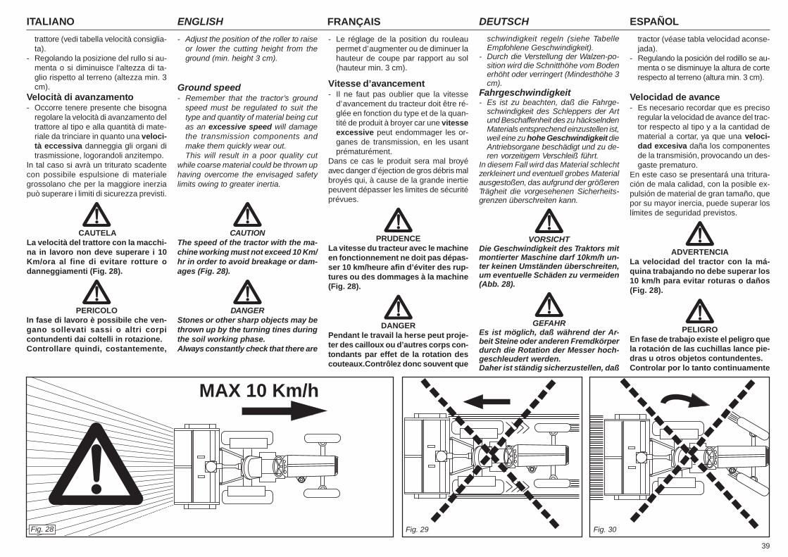
39
ITALIANO ENGLISH FRANÇAIS ESPAÑOLDEUTSCH
trattore (vedi tabella velocità consiglia-ta).
- Regolando la posizione del rullo si au-menta o si diminuisce l'altezza di ta-glio rispetto al terreno (altezza min. 3cm).
Velocità di avanzamento- Occorre tenere presente che bisogna
regolare la velocità di avanzamento deltrattore al tipo e alla quantità di mate-riale da trinciare in quanto una veloci-tà eccessiva danneggia gli organi ditrasmissione, logorandoli anzitempo.
In tal caso si avrà un triturato scadentecon possibile espulsione di materialegrossolano che per la maggiore inerziapuò superare i limiti di sicurezza previsti.
CAUTELALa velocità del trattore con la macchi-na in lavoro non deve superare i 10Km/ora al fine di evitare rotture odanneggiamenti (Fig. 28).
PERICOLOIn fase di lavoro è possibile che ven-gano sollevati sassi o altri corpicontundenti dai coltelli in rotazione.Controllare quindi, costantemente,
- Adjust the position of the roller to raiseor lower the cutting height from theground (min. height 3 cm).
Ground speed- Remember that the tractor’s ground
speed must be regulated to suit thetype and quantity of material being cutas an excessive speed will damagethe transmission components andmake them quickly wear out.This will result in a poor quality cut
while coarse material could be thrown uphaving overcome the envisaged safetylimits owing to greater inertia.
CAUTIONThe speed of the tractor with the ma-chine working must not exceed 10 Km/hr in order to avoid breakage or dam-ages (Fig. 28).
DANGERStones or other sharp objects may bethrown up by the turning tines duringthe soil working phase.Always constantly check that there are
- Le réglage de la position du rouleaupermet d’augmenter ou de diminuer lahauteur de coupe par rapport au sol(hauteur min. 3 cm).
Vitesse d’avancement- Il ne faut pas oublier que la vitesse
d’avancement du tracteur doit être ré-glée en fonction du type et de la quan-tité de produit à broyer car une vitesseexcessive peut endommager les or-ganes de transmission, en les usantprématurément.
Dans ce cas le produit sera mal broyéavec danger d’éjection de gros débris malbroyés qui, à cause de la grande inertiepeuvent dépasser les limites de sécuritéprévues.
PRUDENCELa vitesse du tracteur avec le machineen fonctionnement ne doit pas dépas-ser 10 km/heure afin d’éviter des rup-tures ou des dommages à la machine(Fig. 28).
DANGERPendant le travail la herse peut proje-ter des cailloux ou d’autres corps con-tondants par effet de la rotation descouteaux.Contrôlez donc souvent que
schwindigkeit regeln (siehe TabelleEmpfohlene Geschwindigkeit).
- Durch die Verstellung der Walzen-po-sition wird die Schnitthöhe vom Bodenerhöht oder verringert (Mindesthöhe 3cm).
Fahrgeschwindigkeit- Es ist zu beachten, daß die Fahrge-
schwindigkeit des Schleppers der Artund Beschaffenheit des zu häckselndenMaterials entsprechend einzustellen ist,weil eine zu hohe Geschwindigkeit dieAntriebsorgane beschädigt und zu de-ren vorzeitigem Verschleiß führt.
In diesem Fall wird das Material schlechtzerkleinert und eventuell grobes Materialausgestoßen, das aufgrund der größerenTrägheit die vorgesehenen Sicherheits-grenzen überschreiten kann.
VORSICHTDie Geschwindigkeit des Traktors mitmontierter Maschine darf 10km/h un-ter keinen Umständen überschreiten,um eventuelle Schäden zu vermeiden(Abb. 28).
GEFAHREs ist möglich, daß während der Ar-beit Steine oder anderen Fremdkörperdurch die Rotation der Messer hoch-geschleudert werden.Daher ist ständig sicherzustellen, daß
tractor (véase tabla velocidad aconse-jada).
- Regulando la posición del rodillo se au-menta o se disminuye la altura de corterespecto al terreno (altura min. 3 cm).
Velocidad de avance- Es necesario recordar que es preciso
regular la velocidad de avance del trac-tor respecto al tipo y a la cantidad dematerial a cortar, ya que una veloci-dad excesiva daña los componentesde la transmisión, provocando un des-gaste prematuro.
En este caso se presentará una tritura-ción de mala calidad, con la posible ex-pulsión de material de gran tamaño, quepor su mayor inercia, puede superar loslímites de seguridad previstos.
ADVERTENCIALa velocidad del tractor con la má-quina trabajando no debe superar los10 km/h para evitar roturas o daños(Fig. 28).
PELIGROEn fase de trabajo existe el peligro quela rotación de las cuchillas lance pie-dras u otros objetos contundentes.Controlar por lo tanto continuamente
Fig. 28
MAX 10 Km/h
Fig. 29 Fig. 30
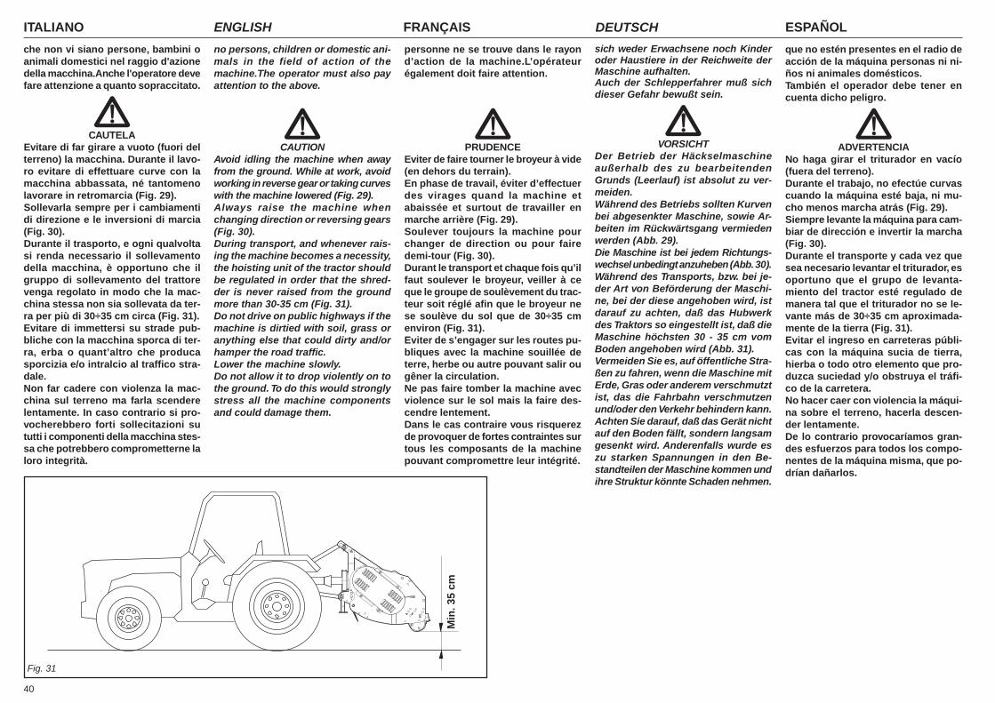
ITALIANO ENGLISH FRANÇAIS ESPAÑOLDEUTSCH
40
che non vi siano persone, bambini oanimali domestici nel raggio d'azionedella macchina.Anche l'operatore devefare attenzione a quanto sopraccitato.
CAUTELAEvitare di far girare a vuoto (fuori delterreno) la macchina. Durante il lavo-ro evitare di effettuare curve con lamacchina abbassata, né tantomenolavorare in retromarcia (Fig. 29).Sollevarla sempre per i cambiamentidi direzione e le inversioni di marcia(Fig. 30).Durante il trasporto, e ogni qualvoltasi renda necessario il sollevamentodella macchina, è opportuno che ilgruppo di sollevamento del trattorevenga regolato in modo che la mac-china stessa non sia sollevata da ter-ra per più di 30÷35 cm circa (Fig. 31).Evitare di immettersi su strade pub-bliche con la macchina sporca di ter-ra, erba o quant’altro che producasporcizia e/o intralcio al traffico stra-dale.Non far cadere con violenza la mac-china sul terreno ma farla scenderelentamente. In caso contrario si pro-vocherebbero forti sollecitazioni sututti i componenti della macchina stes-sa che potrebbero comprometterne laloro integrità.
personne ne se trouve dans le rayond’action de la machine.L’opérateurégalement doit faire attention.
PRUDENCEEviter de faire tourner le broyeur à vide(en dehors du terrain).En phase de travail, éviter d’effectuerdes virages quand la machine etabaissée et surtout de travailler enmarche arrière (Fig. 29).Soulever toujours la machine pourchanger de direction ou pour fairedemi-tour (Fig. 30).Durant le transport et chaque fois qu’ilfaut soulever le broyeur, veiller à ceque le groupe de soulèvement du trac-teur soit réglé afin que le broyeur nese soulève du sol que de 30÷35 cmenviron (Fig. 31).Eviter de s’engager sur les routes pu-bliques avec la machine souillée deterre, herbe ou autre pouvant salir ougêner la circulation.Ne pas faire tomber la machine avecviolence sur le sol mais la faire des-cendre lentement.Dans le cas contraire vous risquerezde provoquer de fortes contraintes surtous les composants de la machinepouvant compromettre leur intégrité.
sich weder Erwachsene noch Kinderoder Haustiere in der Reichweite derMaschine aufhalten.Auch der Schlepperfahrer muß sichdieser Gefahr bewußt sein.
VORSICHTDer Betrieb der Häckselmaschineaußerhalb des zu bearbeitendenGrunds (Leerlauf) ist absolut zu ver-meiden.Während des Betriebs sollten Kurvenbei abgesenkter Maschine, sowie Ar-beiten im Rückwärtsgang vermiedenwerden (Abb. 29).Die Maschine ist bei jedem Richtungs-wechsel unbedingt anzuheben (Abb. 30).Während des Transports, bzw. bei je-der Art von Beförderung der Maschi-ne, bei der diese angehoben wird, istdarauf zu achten, daß das Hubwerkdes Traktors so eingestellt ist, daß dieMaschine höchsten 30 - 35 cm vomBoden angehoben wird (Abb. 31).Vermeiden Sie es, auf öffentliche Stra-ßen zu fahren, wenn die Maschine mitErde, Gras oder anderem verschmutztist, das die Fahrbahn verschmutzenund/oder den Verkehr behindern kann.Achten Sie darauf, daß das Gerät nichtauf den Boden fällt, sondern langsamgesenkt wird. Anderenfalls wurde eszu starken Spannungen in den Be-standteilen der Maschine kommen undihre Struktur könnte Schaden nehmen.
que no estén presentes en el radio deacción de la máquina personas ni ni-ños ni animales domésticos.También el operador debe tener encuenta dicho peligro.
ADVERTENCIANo haga girar el triturador en vacío(fuera del terreno).Durante el trabajo, no efectúe curvascuando la máquina esté baja, ni mu-cho menos marcha atrás (Fig. 29).Siempre levante la máquina para cam-biar de dirección e invertir la marcha(Fig. 30).Durante el transporte y cada vez quesea necesario levantar el triturador, esoportuno que el grupo de levanta-miento del tractor esté regulado demanera tal que el triturador no se le-vante más de 30÷35 cm aproximada-mente de la tierra (Fig. 31).Evitar el ingreso en carreteras públi-cas con la máquina sucia de tierra,hierba o todo otro elemento que pro-duzca suciedad y/o obstruya el tráfi-co de la carretera.No hacer caer con violencia la máqui-na sobre el terreno, hacerla descen-der lentamente.De lo contrario provocaríamos gran-des esfuerzos para todos los compo-nentes de la máquina misma, que po-drían dañarlos.
Fig. 31
Min
. 35
cm
no persons, children or domestic ani-mals in the field of action of themachine.The operator must also payattention to the above.
CAUTIONAvoid idling the machine when awayfrom the ground. While at work, avoidworking in reverse gear or taking curveswith the machine lowered (Fig. 29).Always raise the machine whenchanging direction or reversing gears(Fig. 30).During transport, and whenever rais-ing the machine becomes a necessity,the hoisting unit of the tractor shouldbe regulated in order that the shred-der is never raised from the groundmore than 30-35 cm (Fig. 31).Do not drive on public highways if themachine is dirtied with soil, grass oranything else that could dirty and/orhamper the road traffic.Lower the machine slowly.Do not allow it to drop violently on tothe ground. To do this would stronglystress all the machine componentsand could damage them.

41
ITALIANO ENGLISH FRANÇAIS ESPAÑOLDEUTSCH
3.22 CONSIGLI UTILI PERIL TRATTORISTA
Riportiamo di seguito alcuni utili consigliper problemi che potrebbero presentarsidurante il lavoro.
Eccessivo sminuzzamento delprodotto da trinciare- Sollevare leggermente la macchina dal
terreno regolando l'altezza con le ruo-te (il trincia non deve toccare il terrenocon i coltelli).
- Aumentare la velocità d'avanzamento.
Scarso sminuzzamento del pro-dotto da trinciare- Abbassare leggermente la macchina
sul terreno.- Ridurre la velocità d'avanzamento.- Non lavorare su terreni troppo bagnati.
Intasamento del rotore- Terreno troppo bagnato per lavorare.- Sollevare la macchina dal terreno.- Ridurre la velocità d'avanzamento.- Evitare di lavorare in presenza di erba
molto alta, eventualmente pulire beneai lati del rotore ciò che si è fermatosui supporti per evitare surriscalda-menti eccessivi.
Ingolfamento del vano rotore- Terreno troppo bagnato. Erba molto
alta.- Arrestare il motore.- Accertarsi che tutte le parti in movimen-
to siano ferme.- Pulire accuratamente con adeguate
attrezzature il vano rotore da tutto ciòche si è accumulato.
La macchina rimbalza sul terre-no o vibra- Corpi estranei bloccati fra i coltelli.- Coltelli montati non correttamente sen-
za la disposizione elicoidale o con ilbordo che penetra nel terreno.
- Coltelli consumati o rotti.- Deformazione del rotore dovuta a col-
pi ricevuti nella parte centrale, duranteil lavoro da corpi estranei.
3.22 USEFUL ADVICE FORTHE TRACTOR DRIVER
The following are some useful sugges-tions for problems which might arise dur-ing work.
Excessive cutting of the productto be sheared- Slightly raise the machine from the
ground, adjusting the height with thewheels (the shredder must not touchthe ground with the blades).
- Increase the forward speed.
Scant cutting of the product tobe sheared- Slightly lower the machine to the
ground.- Reduce forward speed.- Do not work on ground that is too damp.
Clogging of the rotor- Ground too wet to work.- Raise the machine from the ground.- Reduce forward speed.- Avoid working in presence of very tall
grass. Eventually clean away what hascollected on sides of rotor in order toprevent excessive overheating.
Clogging in the rotor compart-ment- Soil too wet. Very tall grass.- Stop the engine.- Make sure that all moving parts are at
a standstill.- Thoroughly clean all the accumulated
material from the rotor compartmentwith an adequate tool.
The machine bounces on theground, or vibrates- Foreign bodies are caught in the
blades.- Blades mounted incorrectly, without the
helicoidal arrangement, or with theedge penetrating into the ground.
- Blades worn or broken.- Deformation of the rotor due to blows
received from foreign bodies in thecentral part, during work.
3.22 CONSEILS UTILESPOUR LETRACTORISTE
Nous reportons ci-dessous quelques con-seils utiles concernant les problèmes quipourraient se présenter durant le travail.
Emiettement excessif du produità hacher- Soulever légèrement le machine du
terrain en réglant la hauteur à l’aide desroues (le broyeur ne doit pas toucherle terrain avec les lames).
- Augmenter la vitesse d’avancement.
Emiettement trop faible du pro-duit à hacher- Abaisser légèrement le machine sur le
terrain.- Réduire la vitesse d’avancement.- Ne pas travailler sur des terrains trop
mouillés.
Engorgement du rotor- Terrain trop mouillé pour travailler.- Soulever le machine du terrain.- Réduire la vitesse d’avancement.- Eviter de travailler en présence d’herbe
trop haute, enlever éventuellement lesdéchets qui se sont déposés sur lessupports de chaque côté du rotor pouréviter une surchauffe excessive.
Bourrage du compartiment rotor- Sol trop mouillé. Herbe trop haute.- Stopper le moteur.- S’assurer que toutes les parties en
mouvement sont arrêtées.- Nettoyer soigneusement avec des
équipements appropriés le comparti-ment rotor de tout ce qui s’est accu-mulé.
Le machine rebondit sur le ter-rain ou vibre- Corps étrangers bloqués entre les la-
mes.- Lames montées de façon incorrecte
sans la disposition hélicoïdale ou avecle bord qui pénètre dans le terrain.
- Lames usées ou cassées.- Déformation du rotor due à des coups
donnés dans la partie centrale par descorps étrangers durant le travail.
3.22 RATSCHLÄGE FÜRDEN LENKER
Nachstehend sind einige Ratschläge an-geführt, die dem Lenker des Traktors beieventuell auftretenden Problemen wäh-rend des Betriebs nützlich sein könnten.
Übermäßiges Zerkleinern desMaterials- Die Maschine leicht anheben; dazu die
Räder neu einstellen (die Höhe mußderart eingestellt werden, daß die Mes-ser den Boden nicht berühren).
- Die Fahrgeschwindigkeit erhöhen.
Das Material wird ungenügendzerkleinert- Die Maschine etwas gegen den Boden
absenken.- Die Fahrgeschwindigkeit vermindern.- Nicht bei zu nassem Boden arbeiten.
Verschmutzung des Rotors- Zu nasse Bodenverhältnisse.- Die Maschine leicht anheben.- Die Fahrgeschwindigkeit vermindern- Nicht bei zu hohem Graswuchs arbei-
ten; die Seiten des Rotors von mögli-chen Ablagerungen gut reinigen, umeine Überhitzung zu vermeiden.
Verstopfung des Rotorraums- Boden zu nass. Gras zu hoch.- Den Motor anhalten.- Sicherstellen, dass alle beweglichen
Teile still stehen.- Den Rotorraum mit dazu passender
Vorrichtung sorgfältig reinigen und al-les, was sich darin angesammelt hat,entfernen.
Die Maschine arbeitet ruckartigoder vibriert- Fremdkörper sind zwischen den Mes-
sern blockiert.- Falsch montierte Messer - entweder
ohne schraubenförmige.- Falsch montierte Messer - entweder
ohne schraubenförmige Anordnung,oder so montiert, daß die Messer inden Boden greifen.
- Abgenutzte oder schadhafte Messer.- Verformung des Rotors aufgrund von
Schlägen (eventuell durch Fremdkör-per) an dessen Mitte.
3.22 CONSEJOS ÚTILESPARA EL TRACTORISTA
A continuación, indicamos algunos con-sejos útiles para los problemas que sepueden presentar durante el trabajo.
Trituración excesiva del produc-to por picar- Levante ligeramente la máquina del
terreno, ajustando la altura con las rue-das (el triturador no tiene que tocar elterreno con las cuchillas).
- Aumente la velocidad de avance.
Trituración escasa del productopor picar- Baje ligeramente la máquina sobre el
terreno.- Reduzca la velocidad de avance.- No trabaje sobre terrenos muy mojados.
Atascamiento del rotor- Terreno muy mojado para trabajar.- Levante la máquina del terreno.- Reduzca la velocidad de avance.- No trabaje con hierbas muy altas,
eventualmente, limpie perfectamentede los costados del rotor lo que se acu-muló sobre los soportes, para evitarsobrecalentamientos excesivos.
Ahogado del compartimiento rotor- Terreno demasiado mojado. Vegeta-
ción demasiado alta.- Parar el motor.- Cerciorarse que todas las partes en
movimiento estén paradas.- Quitar escrupulosamente con
equipamientos adecuados todo lo quese haya acumulado en el comparti-miento rotor.
El triturador salta sobre el terre-no o vibra- Hay cuerpos extraños bloqueados en-
tre las cuchillas.- Las cuchillas no han sido instaladas
correctamente, sin la disposiciónhelicoidal o con el borde que penetraen el terreno.
- Las cuchillas están desgastadas o rotas.- El rotor está deformado a causa de
golpes que ha recibido en la parte cen-tral durante el trabajo, producidos porcuerpos extraños.
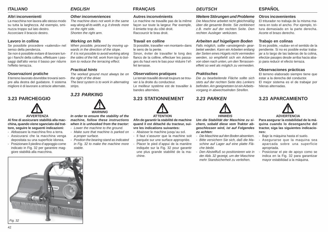
ITALIANO ENGLISH FRANÇAIS ESPAÑOLDEUTSCH
42
Altri inconvenientiLa macchina non lavora allo stesso modosu tutta la larghezza. Ad esempio, smi-nuzza troppo sul lato destro.Accorciare il braccio destro.
Lavoro in collinaSe possibile procedere «salendo» nelsenso della pendenza.Se non è possibile evitare di lavorare lun-go i fianchi della collina, effettuare i pas-saggi dall'alto verso il basso per ridurrel'effetto terrazza.
Osservazioni praticheIl terreno lavorato dovrebbe trovarsi sem-pre alla destra del guidatore. Il sistemamigliore è di lavorare a striscie alternate.
3.23 PARCHEGGIO
AVVERTENZAAl fine di assicurare stabilità alla mac-china, quando viene sganciato dal trat-tore, seguire le seguenti indicazioni:- Abbassare la macchina fino a terra.- Assicurarsi che la macchina venga
depositata su una superficie idonea.- Posizionare il piedino d’appoggio come
indicato in Fig. 32 per garantire mag-giore stabilità alla macchina.
Other inconveniencesThe machine does not work in the sameway along all its width, e.g. it shreds moreon the right side.Shorten the right arm.
Working on hillsWhen possible, proceed by moving up-wards in the direction of the slope.If it is not possible to avoid working alongthe sides of the hill, work from top to bot-tom to reduce the terracing effect.
Practical hintsThe worked ground must always be onthe right of the driver.The best system is to work in alternatingstrips.
3.23 PARKING
WARNINGIn order to ensure the stability of themachine, follow these instructionswhen it is unhooked from the tractor:- Lower the machine to the ground.- Make sure that machine is parked on
a proper surface.- Position the bearing stand as indicated
in Fig. 32 to make the machine morestable.
Autres inconvénientsLe machine ne travaille pas de la mêmefaçon sur toute la largeur. Par exemple,il émiette trop du côté droit.Raccourcir le bras droit.
Travail en collineSi possible, travailler «en montant» dansle sens de la pente.Sinon, éviter de travailler le long desflancs de la colline, effectuer les passa-ges du haut vers le bas pour réduire l’ef-fet terrasse.
Observations pratiquesLe terrain travaillé devrait toujours se trou-ver à la droite du conducteur.Le meilleur système est de travailler àbandes alternées.
3.23 STATIONNEMENT
ATTENTIONAfin de garantir la stabilité de machinequand il est détaché du tracteur, sui-vre les indications suivantes:- Abaisser le machine jusqu’au sol.- Il faut s’assurer que la machine soit
parquée sur une surface appropriée.- Placer le pied d’appui de la manière
indiquée sur la Fig. 32 pour garantirune plus grande stabilité de la ma-chine.
Weitere Störungen und ProblemeDie Maschine arbeitet nicht gleichmäßigüber die gesamte Breite. Sie zerkleinertz.B. mehr auf der rechten Seite. Denrechten Ausleger verkürzen.
Arbeiten auf hügeligem BodenFalls möglich, sollte «ansteigend» gear-beitet werden. Kann ein Arbeiten entlangder Seiten eines Hügels nicht vermiedenwerden, so empfiehlt sich ein Arbeitenvon oben nach unten, um den Terrassen-effekt so weit als möglich zu vermeiden.
PraktischesDie zu bearbeitende Fläche sollte sichstets auf der rechten Seite des Lenkersbefinden. Am geeignetsten ist ein Arbeits-vorgang in abwechselnden Streifen.
3.23 PARKEN
HINWEISUm die Stabilität der Maschine zu si-chern, sobald diese vom Traktor ab-geschlossen wird, ist auf Folgendeszu achten:- Die Maschine auf den Boden absenken.- Bitte versichern Sie sich, daß die Ma-
schine auf Lager auf eine platte Flä-che bleibt.
- Den Abstellfuß so positionieren wie inder Abb. 32 gezeigt, um der Maschinemehr Standsicherheit zu verleihen.
Otros incovenientesEl triturador no trabaja de la misma ma-nera en todo el ancho. Por ejemplo, tri-tura demasiado en la parte derecha.Acorte el brazo derecho.
Trabajo en colinasSi es posible, «suba» en el sentido de lapendiente. Si no es posible evitar traba-jar a lo largo de las laderas de la colina,efectúe pasajes desde arriba hacia aba-jo para reducir el efecto terraza.
Observaciones prácticasEl terreno elaborado siempre tiene queestar a la derecha del conductor.El mejor sistema es el de trabajar porhileras alternadas.
3.23 APARCAMIENTO
ADVERTENCIAPara asegurar la estabilidad de la má-quina cuando lo desenganche deltractor, siga las siguientes indicacio-nes:- Baje la máquina hasta el suelo.- Asegurarse que la maquina sea
aparcada sobre una superficieapropriada.
- Posicionar el pie de apoyo como seindica en la Fig. 32 para garantizarmayor estabilidad a la máquina.
Fig. 32
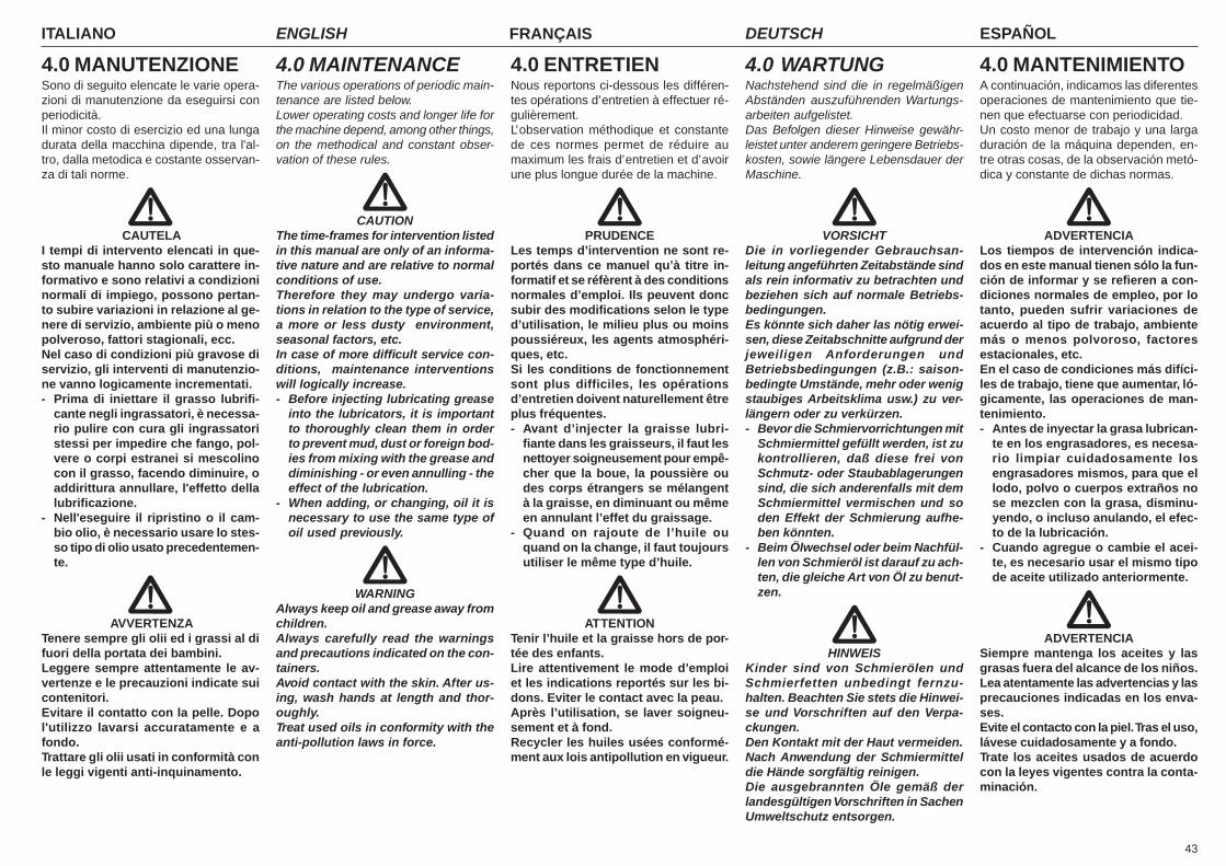
43
ITALIANO ENGLISH FRANÇAIS ESPAÑOLDEUTSCH
4.0 MANUTENZIONESono di seguito elencate le varie opera-zioni di manutenzione da eseguirsi conperiodicità.Il minor costo di esercizio ed una lungadurata della macchina dipende, tra l'al-tro, dalla metodica e costante osservan-za di tali norme.
CAUTELAI tempi di intervento elencati in que-sto manuale hanno solo carattere in-formativo e sono relativi a condizioninormali di impiego, possono pertan-to subire variazioni in relazione al ge-nere di servizio, ambiente più o menopolveroso, fattori stagionali, ecc.Nel caso di condizioni più gravose diservizio, gli interventi di manutenzio-ne vanno logicamente incrementati.- Prima di iniettare il grasso lubrifi-
cante negli ingrassatori, è necessa-rio pulire con cura gli ingrassatoristessi per impedire che fango, pol-vere o corpi estranei si mescolinocon il grasso, facendo diminuire, oaddirittura annullare, l'effetto dellalubrificazione.
- Nell'eseguire il ripristino o il cam-bio olio, è necessario usare lo stes-so tipo di olio usato precedentemen-te.
AVVERTENZATenere sempre gli olii ed i grassi al difuori della portata dei bambini.Leggere sempre attentamente le av-vertenze e le precauzioni indicate suicontenitori.Evitare il contatto con la pelle. Dopol'utilizzo lavarsi accuratamente e afondo.Trattare gli olii usati in conformità conle leggi vigenti anti-inquinamento.
4.0 MAINTENANCEThe various operations of periodic main-tenance are listed below.Lower operating costs and longer life forthe machine depend, among other things,on the methodical and constant obser-vation of these rules.
CAUTIONThe time-frames for intervention listedin this manual are only of an informa-tive nature and are relative to normalconditions of use.Therefore they may undergo varia-tions in relation to the type of service,a more or less dusty environment,seasonal factors, etc.In case of more difficult service con-ditions, maintenance interventionswill logically increase.- Before injecting lubricating grease
into the lubricators, it is importantto thoroughly clean them in orderto prevent mud, dust or foreign bod-ies from mixing with the grease anddiminishing - or even annulling - theeffect of the lubrication.
- When adding, or changing, oil it isnecessary to use the same type ofoil used previously.
WARNINGAlways keep oil and grease away fromchildren.Always carefully read the warningsand precautions indicated on the con-tainers.Avoid contact with the skin. After us-ing, wash hands at length and thor-oughly.Treat used oils in conformity with theanti-pollution laws in force.
4.0 ENTRETIENNous reportons ci-dessous les différen-tes opérations d’entretien à effectuer ré-gulièrement.L’observation méthodique et constantede ces normes permet de réduire aumaximum les frais d’entretien et d’avoirune plus longue durée de la machine.
PRUDENCELes temps d’intervention ne sont re-portés dans ce manuel qu’à titre in-formatif et se réfèrent à des conditionsnormales d’emploi. Ils peuvent doncsubir des modifications selon le typed’utilisation, le milieu plus ou moinspoussiéreux, les agents atmosphéri-ques, etc.Si les conditions de fonctionnementsont plus difficiles, les opérationsd’entretien doivent naturellement êtreplus fréquentes.- Avant d’injecter la graisse lubri-
fiante dans les graisseurs, il faut lesnettoyer soigneusement pour empê-cher que la boue, la poussière oudes corps étrangers se mélangentà la graisse, en diminuant ou mêmeen annulant l’effet du graissage.
- Quand on rajoute de l’huile ouquand on la change, il faut toujoursutiliser le même type d’huile.
ATTENTIONTenir l’huile et la graisse hors de por-tée des enfants.Lire attentivement le mode d’emploiet les indications reportés sur les bi-dons. Eviter le contact avec la peau.Après l’utilisation, se laver soigneu-sement et à fond.Recycler les huiles usées conformé-ment aux lois antipollution en vigueur.
4.0 WARTUNGNachstehend sind die in regelmäßigenAbständen auszuführenden Wartungs-arbeiten aufgelistet.Das Befolgen dieser Hinweise gewähr-leistet unter anderem geringere Betriebs-kosten, sowie längere Lebensdauer derMaschine.
VORSICHTDie in vorliegender Gebrauchsan-leitung angeführten Zeitabstände sindals rein informativ zu betrachten undbeziehen sich auf normale Betriebs-bedingungen.Es könnte sich daher las nötig erwei-sen, diese Zeitabschnitte aufgrund derjeweiligen Anforderungen undBetriebsbedingungen (z.B.: saison-bedingte Umstände, mehr oder wenigstaubiges Arbeitsklima usw.) zu ver-längern oder zu verkürzen.- Bevor die Schmiervorrichtungen mit
Schmiermittel gefüllt werden, ist zukontrollieren, daß diese frei vonSchmutz- oder Staubablagerungensind, die sich anderenfalls mit demSchmiermittel vermischen und soden Effekt der Schmierung aufhe-ben könnten.
- Beim Ölwechsel oder beim Nachfül-len von Schmieröl ist darauf zu ach-ten, die gleiche Art von Öl zu benut-zen.
HINWEISKinder sind von Schmierölen undSchmierfetten unbedingt fernzu-halten. Beachten Sie stets die Hinwei-se und Vorschriften auf den Verpa-ckungen.Den Kontakt mit der Haut vermeiden.Nach Anwendung der Schmiermitteldie Hände sorgfältig reinigen.Die ausgebrannten Öle gemäß derlandesgültigen Vorschriften in SachenUmweltschutz entsorgen.
4.0 MANTENIMIENTOA continuación, indicamos las diferentesoperaciones de mantenimiento que tie-nen que efectuarse con periodicidad.Un costo menor de trabajo y una largaduración de la máquina dependen, en-tre otras cosas, de la observación metó-dica y constante de dichas normas.
ADVERTENCIALos tiempos de intervención indica-dos en este manual tienen sólo la fun-ción de informar y se refieren a con-diciones normales de empleo, por lotanto, pueden sufrir variaciones deacuerdo al tipo de trabajo, ambientemás o menos polvoroso, factoresestacionales, etc.En el caso de condiciones más difíci-les de trabajo, tiene que aumentar, ló-gicamente, las operaciones de man-tenimiento.- Antes de inyectar la grasa lubrican-
te en los engrasadores, es necesa-rio limpiar cuidadosamente losengrasadores mismos, para que ellodo, polvo o cuerpos extraños nose mezclen con la grasa, disminu-yendo, o incluso anulando, el efec-to de la lubricación.
- Cuando agregue o cambie el acei-te, es necesario usar el mismo tipode aceite utilizado anteriormente.
ADVERTENCIASiempre mantenga los aceites y lasgrasas fuera del alcance de los niños.Lea atentamente las advertencias y lasprecauciones indicadas en los enva-ses.Evite el contacto con la piel. Tras el uso,lávese cuidadosamente y a fondo.Trate los aceites usados de acuerdocon la leyes vigentes contra la conta-minación.

ITALIANO ENGLISH FRANÇAIS ESPAÑOLDEUTSCH
44
4.1 PRIME 8 ORELAVORATIVE
- Dopo le prime 8 ore lavorative a cui lamacchina è stata sottoposta, effettua-re un accurato controllo dello statogenerale della macchina stessa.In particolare, dopo aver controllatol'usura dei coltelli, serrare a fondo ul-teriormente le viti. In tale occasione èbene effettuare un controllo del serrag-gio delle viti e bulloni di tutta la mac-china.
4.2 OGNI 8 ORELAVORATIVE
- Ingrassare le crociere dell'alberocardanico.
- Ingrassare i cuscinetti del rotore.- Verificare il serraggio dei bulloni di fis-
saggio dei coltelli.- Aprire il cofano posteriore e verificare
che il vano rotore sia pulito e sgombroda eventuali residui di lavorazione.
4.3 OGNI 50 ORELAVORATIVE
- Verificare il livello olio nella scatola delmoltiplicatore, eventualmente ripristi-narlo fino all’altezza del foro di livello(5 Fig. 33).
4.4 OGNI 400 ORELAVORATIVE
- Effettuare il cambio completo dell'oliodel moltiplicatore, scaricando comple-tamente l'olio dal tappo di scarico po-sto sotto la scatola moltiplicatore (4Fig. 33).
4.5 MESSA A RIPOSOA fine stagione, o nel caso si preveda unlungo periodo di riposo, è consigliabile:- Lavare la macchina soprattutto da con-
cimi e da prodotti chimici ed asciugarlo.- Controllarla accuratamente ed even-
tualmente sostituire le parti danneggia-te o usurate.
- Serrare a fondo tutte le viti e i bulloni, inparticolare quelli che fissano i coltelli.
4.1 FIRST 8 HOURSSERVICE
- Carefully check the general conditionof the machine after the first 8 hoursservice.In particular, after having checked thetines for wear, tighten the screws.At that time, it is advisable to check thatall screws and bolts are correctlytorqued.
4.2 EVERY 8 WORKHOURS
- Grease the cardan shaft cross journals.- Grease the bearings of the rotor.- Check the tightness of the fastening
bolts of the blades.- Open the rear hood and check to make
sure that the rotor housing is clean andfree from plant residues.
4.3 EVERY 50 HOURSOF WORK
- Check the oil level in the overdrive box,filling it up, if necessary, to the notchon the indicator (5 Fig. 33).
4.4 EVERY 400 HOURS OFWORK
- Carry out a complete oil change of theoverdrive, discharging all the oil fromthe discharge cap located below theoverdrive box (4 Fig. 33).
4.5 STORAGEProceed in the following way at the endof the season or if the machine is to re-main unused for a long period of time:- Wash the machine and dry it. Make
sure that all fertilizer and chemicalproducts have been removed.
- Carefully check the implement and re-place any damaged or worn parts.
- Fully tighten all screws and bolts, par-ticularly the ones that fix the tines.
4.1 APRES LES 8PREMIERES HEURESDE TRAVAIL
- Après le 8 premières heures de travailde la machine, contrôlez attentivementson état général.En particulier, après avoir contrôlél’usure des couteaux, serrez à fond lesvis. A cette occasion vérifiez égalementle serrage des vis et des boulons detoute la machine.
4.2 TOUTES LES 8HEURES DE TRAVAIL
- Graissez les croisillons de l’arbre àcardans.
- Graisser les roulements du rotor.- Contrôler le serrage des boulons de
fixation des lames.- Ouvrir le capot arrière et vérifier que le
compartiment du rotor est propre, sansrésidus du travail effectué.
4.3 TOUTES LES 50HEURES DE TRAVAIL
- Contrôler le niveau d’huile dans le boî-tier du multiplicateur, au besoin rajou-ter de l’huile jusqu’au repère qui setrouve sur la jauge (5 Fig. 33).
4.4 TOUTES LES 400HEURES DE TRAVAIL
- Changer complètement l’huile du mul-tiplicateur, en évacuant l’huile par lebouchon de vidange qui se trouve sousle boîtier du multiplicateur (4 Fig. 33).
4.5 REMISSAGEA la fin de la saison ou lorsque vous pré-voyez une longue période d’inactivité,prenez les précautions suivantes:- Lavez l’appareil en enlevant surtout les
engrais et les produits chimiques, etséchez-le soigneusement.
- Contrôlez attentivement l’appareil:remplacez les parties usées ou endom-magées.
- Serrez à fond toutes les vis et les bou-lons, en particulier celles des couteaux.
4.1 ERSTE 8BETRIEBSSTUNDEN
- Nach den ersten 8 Betriebsstunden istdie Maschine einer sorgfältigen Kontrol-le hinsichtlich ihres Allgemein-zustandes zu unterziehen. Nach derPrüfung des Verschleißzustandes derMesser sind insbesondere die Schrau-ben. Dabei sollten alle Schrauben undSchraubbolzen der Maschine auf fes-ten Sitz geprüft werden.
4.2 ALLE 8BETRIEBSSTUNDEN
- Die Kreuzstücke der Gelenkwelleschmieren.
- Die Lager des Rotors schmieren- Die Befestigungsbolzen der Messer
festziehen.- Die hintere Haube öffnen und sicher-
stellen, dass der Rotorraum sauber istund keine etwaigen Verarbeitungsresteenthält.
4.3 ALLE 50BETRIEBSSTUNDEN
- Den Ölstand im Übersetzungsgetriebe-gehäuse prüfen und eventuell bis zumFüllstrich auffüllen (5 Abb. 33).
4.4 ALLE 400BETRIEBSSTUNDEN
- Das gesamte Öl des Übersetzungs-getriebes wechseln. Das Öl vollkom-men über die Ablaßöffnung, die sichauf der Unterseite des Gehäuses be-findet, auslaufen lassen (4 Abb. 33).
4.5 RUHEPERIODENAm Ende der Saison oder, wenn eine län-gere Ruhepause vorgesehen ist, mußman wie folgt vorgehen:- Den Maschine gründlich reinigen, vor al-
lem Dünger- und/oder Chemikalienrestegut entfernen, um ihn dann zu trocknen.
- Auf das Vorhandensein etwaiger Schä-den oder Verschleißstellen prüfen unddie schadhaften Teile ersetzen.
- Alle Schrauben und Schraubbolzenfest anziehen, vor allem diejenigen zurMesserbefestigung.
4.1 PRIMERAS 8 HORASDE TRABAJO
- Después de las primeras 8 horas detrabajo de la máquina, efectuar un cui-dadoso control general de la misma.En especial, después de controlar eldesgaste de las cuchillas, ajustar afondo los tornillos. En esta ocasión esaconsejable efectuar un control delajuste de todos los tornillos y bulonesde la máquina.
4.2 CADA 8 HORAS DETRABAJO
- Engrasar las crucetas del árbolcardánico.
- Engrase los cojinetes de rotación.- Controle que los pernos de sujeción
de las cuchillas estén biene apretados.- Abrir el capot trasero y controlar que
el compartimiento rotor esté limpio ylibre de todo residuo de elaboración.
4.3 CADA 50 HORAS DETRABAJO
- Controle el nivel de aceite en la cajadel multiplicador, si es necesario, res-tablézcalo hasta la muesca del nivel(5 Fig. 33).
4.4 CADA 400 HORAS DETRABAJO
- Cambie totalmente el aceite delmultiplicador, descargándolo por el ta-pón de descarga que está colocado aba-jo de la caja del multiplicador (4 Fig. 33).
4.5 PERIODOS DE REPOSOAl finalizar la estación o siempre que pre-vemos un período de inactividad prolon-gado aconsejamos:- Lavar la máquina, eliminando sobre
todo abonos y productos químicos; lue-go secarla.
- Controlarla cuidadosamente y even-tualmente sustituir las partes dañadaso gastadas.
- Ajustar a fondo todos los tornillos y losbulones, en particular aquellos que fi-jan las cuchillas.
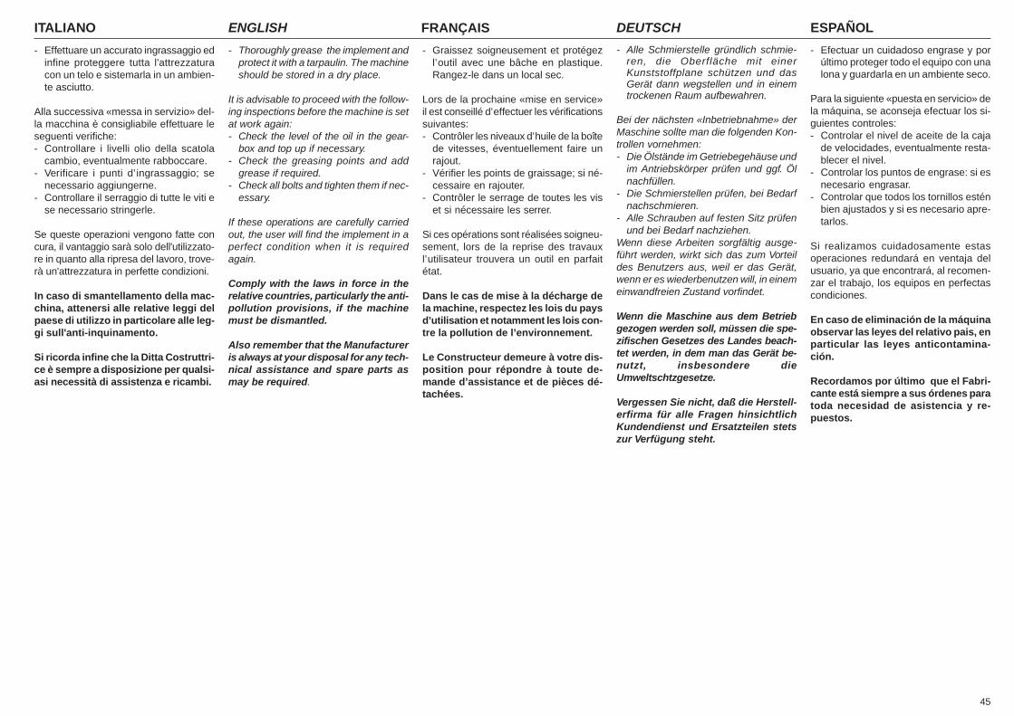
45
ITALIANO ENGLISH FRANÇAIS ESPAÑOLDEUTSCH
- Effettuare un accurato ingrassaggio edinfine proteggere tutta l'attrezzaturacon un telo e sistemarla in un ambien-te asciutto.
Alla successiva «messa in servizio» del-la macchina è consigliabile effettuare leseguenti verifiche:- Controllare i livelli olio della scatola
cambio, eventualmente rabboccare.- Verificare i punti d’ingrassaggio; se
necessario aggiungerne.- Controllare il serraggio di tutte le viti e
se necessario stringerle.
Se queste operazioni vengono fatte concura, il vantaggio sarà solo dell'utilizzato-re in quanto alla ripresa del lavoro, trove-rà un'attrezzatura in perfette condizioni.
In caso di smantellamento della mac-china, attenersi alle relative leggi delpaese di utilizzo in particolare alle leg-gi sull'anti-inquinamento.
Si ricorda infine che la Ditta Costruttri-ce è sempre a disposizione per qualsi-asi necessità di assistenza e ricambi.
- Thoroughly grease the implement andprotect it with a tarpaulin. The machineshould be stored in a dry place.
It is advisable to proceed with the follow-ing inspections before the machine is setat work again:- Check the level of the oil in the gear-
box and top up if necessary.- Check the greasing points and add
grease if required.- Check all bolts and tighten them if nec-
essary.
If these operations are carefully carriedout, the user will find the implement in aperfect condition when it is requiredagain.
Comply with the laws in force in therelative countries, particularly the anti-pollution provisions, if the machinemust be dismantled.
Also remember that the Manufactureris always at your disposal for any tech-nical assistance and spare parts asmay be required.
- Graissez soigneusement et protégezl’outil avec une bâche en plastique.Rangez-le dans un local sec.
Lors de la prochaine «mise en service»il est conseillé d’effectuer les vérificationssuivantes:- Contrôler les niveaux d’huile de la boîte
de vitesses, éventuellement faire unrajout.
- Vérifier les points de graissage; si né-cessaire en rajouter.
- Contrôler le serrage de toutes les viset si nécessaire les serrer.
Si ces opérations sont réalisées soigneu-sement, lors de la reprise des travauxl’utilisateur trouvera un outil en parfaitétat.
Dans le cas de mise à la décharge dela machine, respectez les lois du paysd’utilisation et notamment les lois con-tre la pollution de l’environnement.
Le Constructeur demeure à votre dis-position pour répondre à toute de-mande d’assistance et de pièces dé-tachées.
- Alle Schmierstelle gründlich schmie-ren, die Oberfläche mit einerKunststoffplane schützen und dasGerät dann wegstellen und in einemtrockenen Raum aufbewahren.
Bei der nächsten «Inbetriebnahme» derMaschine sollte man die folgenden Kon-trollen vornehmen:- Die Ölstände im Getriebegehäuse und
im Antriebskörper prüfen und ggf. Ölnachfüllen.
- Die Schmierstellen prüfen, bei Bedarfnachschmieren.
- Alle Schrauben auf festen Sitz prüfenund bei Bedarf nachziehen.
Wenn diese Arbeiten sorgfältig ausge-führt werden, wirkt sich das zum Vorteildes Benutzers aus, weil er das Gerät,wenn er es wiederbenutzen will, in einemeinwandfreien Zustand vorfindet.
Wenn die Maschine aus dem Betriebgezogen werden soll, müssen die spe-zifischen Gesetzes des Landes beach-tet werden, in dem man das Gerät be-nutzt, insbesondere dieUmweltschtzgesetze.
Vergessen Sie nicht, daß die Herstell-erfirma für alle Fragen hinsichtlichKundendienst und Ersatzteilen stetszur Verfügung steht.
- Efectuar un cuidadoso engrase y porúltimo proteger todo el equipo con unalona y guardarla en un ambiente seco.
Para la siguiente «puesta en servicio» dela máquina, se aconseja efectuar los si-guientes controles:- Controlar el nivel de aceite de la caja
de velocidades, eventualmente resta-blecer el nivel.
- Controlar los puntos de engrase: si esnecesario engrasar.
- Controlar que todos los tornillos esténbien ajustados y si es necesario apre-tarlos.
Si realizamos cuidadosamente estasoperaciones redundará en ventaja delusuario, ya que encontrará, al recomen-zar el trabajo, los equipos en perfectascondiciones.
En caso de eliminación de la máquinaobservar las leyes del relativo pais, enparticular las leyes anticontamina-ción.
Recordamos por último que el Fabri-cante está siempre a sus órdenes paratoda necesidad de asistencia y re-puestos.
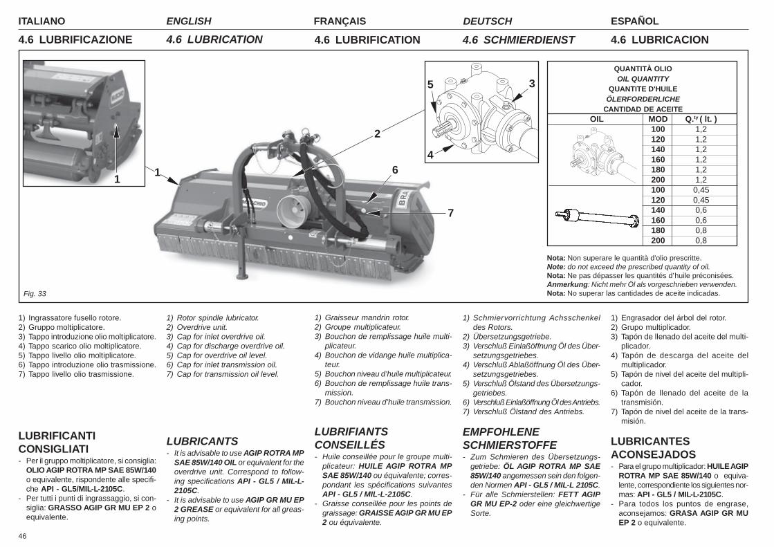
ITALIANO ENGLISH FRANÇAIS ESPAÑOLDEUTSCH
46
Fig. 33
4.6 LUBRIFICAZIONE 4.6 LUBRICATION 4.6 LUBRIFICATION 4.6 LUBRICACION
QUANTITÀ OLIOOIL QUANTITY
QUANTITE D'HUILEÖLERFORDERLICHE
CANTIDAD DE ACEITEOIL MOD Q.ty ( lt. )
100 1,2120 1,2140 1,2160 1,2180 1,2200 1,2100 0,45120 0,45140 0,6160 0,6180 0,8200 0,8
Nota: Non superare le quantità d'olio prescritte.Note: do not exceed the prescribed quantity of oil.Nota: Ne pas dépasser les quantités d’huile préconisées.Anmerkung: Nicht mehr Öl als vorgeschrieben verwenden.Nota: No superar las cantidades de aceite indicadas.
3
4
5
6
7
1
1) Ingrassatore fusello rotore.2) Gruppo moltiplicatore.3) Tappo introduzione olio moltiplicatore.4) Tappo scarico olio moltiplicatore.5) Tappo livello olio moltiplicatore.6) Tappo introduzione olio trasmissione.7) Tappo livello olio trasmissione.
LUBRIFICANTICONSIGLIATI- Per il gruppo moltiplicatore, si consiglia:
OLIO AGIP ROTRA MP SAE 85W/140o equivalente, rispondente alle specifi-che API - GL5/MIL-L-2105C.
- Per tutti i punti di ingrassaggio, si con-siglia: GRASSO AGIP GR MU EP 2 oequivalente.
1) Rotor spindle lubricator.2) Overdrive unit.3) Cap for inlet overdrive oil.4) Cap for discharge overdrive oil.5) Cap for overdrive oil level.6) Cap for inlet transmission oil.7) Cap for transmission oil level.
LUBRICANTS- It is advisable to use AGIP ROTRA MP
SAE 85W/140 OIL or equivalent for theoverdrive unit. Correspond to follow-ing specifications API - GL5 / MIL-L-2105C.
- It is advisable to use AGIP GR MU EP2 GREASE or equivalent for all greas-ing points.
1) Schmiervorrichtung Achsschenkeldes Rotors.
2) Übersetzungsgetriebe.3) Verschluß Einlaßöffnung Öl des Über-
setzungsgetriebes.4) Verschluß Ablaßöffnung Öl des Über-
setzungsgetriebes.5) Verschluß Ölstand des Übersetzungs-
getriebes.6) Verschluß Einlaßöffnung Öl des Antriebs.7) Verschluß Ölstand des Antriebs.
EMPFOHLENESCHMIERSTOFFE- Zum Schmieren des Übersetzungs-
getriebe: ÖL AGIP ROTRA MP SAE85W/140 angemessen sein den folgen-den Normen API - GL5 / MIL-L 2105C.
- Für alle Schmierstellen: FETT AGIPGR MU EP-2 oder eine gleichwertigeSorte.
1) Graisseur mandrin rotor.2) Groupe multiplicateur.3) Bouchon de remplissage huile multi-
plicateur.4) Bouchon de vidange huile multiplica-
teur.5) Bouchon niveau d’huile multiplicateur.6) Bouchon de remplissage huile trans-
mission.7) Bouchon niveau d’huile transmission.
LUBRIFIANTSCONSEILLÉS- Huile conseillée pour le groupe multi-
plicateur: HUILE AGIP ROTRA MPSAE 85W/140 ou équivalente; corres-pondant les spécifications suivantesAPI - GL5 / MIL-L-2105C.
- Graisse conseillée pour les points degraissage: GRAISSE AGIP GR MU EP2 ou équivalente.
1) Engrasador del árbol del rotor.2) Grupo multiplicador.3) Tapón de llenado del aceite del multi-
plicador.4) Tapón de descarga del aceite del
multiplicador.5) Tapón de nivel del aceite del multipli-
cador.6) Tapón de llenado del aceite de la
transmisión.7) Tapón de nivel del aceite de la trans-
misión.
LUBRICANTESACONSEJADOS- Para el grupo multiplicador: HUILE AGIP
ROTRA MP SAE 85W/140 o equiva-lente, correspondiente los siguientes nor-mas: API - GL5 / MIL-L-2105C.
- Para todos los puntos de engrase,aconsejamos: GRASA AGIP GR MUEP 2 o equivalente.
1
2
4.6 SCHMIERDIENST
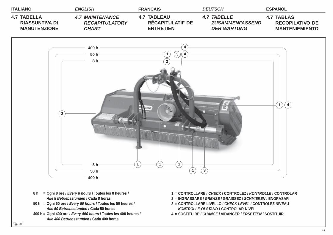
47
ITALIANO ENGLISH FRANÇAIS ESPAÑOLDEUTSCH
4.7 TABELLARIASSUNTIVA DIMANUTENZIONE
4.7 MAINTENANCERECAPITULATORYCHART
4.7 TABLEAURÉCAPITULATIF DEENTRETIEN
4.7 TABELLEZUSAMMENFASSENDDER WARTUNG
4.7 TABLASRECOPILATIVO DEMANTENIEMIENTO
8 h = Ogni 8 ore / Every 8 hours / Toutes les 8 heures /Alle 8 Betriebsstunden / Cada 8 horas
50 h = Ogni 50 ore / Every 50 hours / Toutes les 50 heures /Alle 50 Betriebsstunden / Cada 50 horas
400 h = Ogni 400 ore / Every 400 hours / Toutes les 400 heures /Alle 400 Betriebsstunden / Cada 400 horas
400 h
50 h
8 h
8 h
50 h
400 h
1 = CONTROLLARE / CHECK / CONTROLEZ / KONTROLLE / CONTROLAR2 = INGRASSARE / GREASE / GRAISSEZ / SCHMIEREN / ENGRASAR3 = CONTROLLARE LIVELLO / CHECK LEVEL / CONTROLEZ NIVEAU
KONTROLLE ÖLSTAND / CONTROLAR NIVEL4 = SOSTITUIRE / CHANGE / VIDANGER / ERSETZEN / SOSTITUIR
2
2
3
11
1
Fig. 34
4
1
1
4
4
1 3
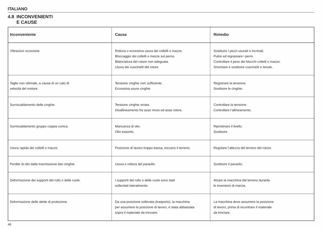
ITALIANO ENGLISH FRANÇAIS ESPAÑOLDEUTSCH
48
Inconveniente Causa Rimedio
Vibrazioni eccessive Rottura o eccessiva usura dei coltelli o mazze. Sostituire i pezzi usurati o incrinati.
Bloccaggio dei coltelli o mazze sul perno. Pulire ed ingrassare i perni.
Bilanciatura del rotore non adeguata. Controllare il peso dei blocchi coltelli o mazze.
Usura dei cuscinetti del rotore Smontare e sostituire cuscinetti e tenute.
Taglio non ottimale, a causa di un calo di Tensione cinghie non sufficiente. Registrare la tensione.
velocità del motore. Eccessiva usura cinghie. Sostituire le cinghie.
Surriscaldamento delle cinghie. Tensione cinghie errata. Controllare la tensione.
Disallineamento fra asse rinvio ed asse rotore. Controllare l’allineamento.
Surriscaldamento gruppo coppia conica. Mancanza di olio. Ripristinare il livello.
Olio esaurito. Sostituire.
Usura rapida dei coltelli o mazze. Posizione di lavoro troppo bassa, toccano il terreno. Regolare l’altezza del terreno del rotore.
Perdite di olio dalla trasmissione lato cinghie. Usura e rottura del paraolio. Sostituire il paraolio.
Deformazione dei supporti del rullo o delle ruote. I supporti del rullo o delle ruote sono stati Alzare la macchina dal terreno durante
sollecitati lateralmente. le inversioni di marcia.
Deformazione delle alette di protezione. Da una posizione sollevata (trasporto), la macchina La macchina deve assumere la posizione
per assumere la posizione di lavoro, è stata abbassata di lavoro, prima di incontrare il materiale
sopra il materiale da trinciare. da trinciare.
4.8 INCONVENIENTIE CAUSE

49
ITALIANO ENGLISH FRANÇAIS ESPAÑOLDEUTSCH
Inconvenience Cause Remedy
Excessive vibration. Breakage or excessive wear of blades and hammers. Replace the worn or cracked pieces.Blades or hammers blocked on pin. Clean and grease the pins.Inadequate balancing of rotor. Check the weight of the of the blades/hammers blockWear of rotor bearings. Remove and replace bearings and seals.
Imperfect cut due to lowering of engine speed. Belt tension insufficient. Regulate tension.Belts excessively worn. Replace belts.
Overheating of belts. Incorrect tension of belts. Check tension.Transmission axis and rotor axis out of alignment. Check alignment.
Overheating of bevel gear pair. Lack of oil. Add oil to proper level.Oil depleted. Replace.
Rapid wearing of blades or hammers. Work position too low, blades touching ground. Adjust height of rotor from ground.Loss of oil from transmission, belt side. Wear and breakage of oil seal. Replace seal.Deformation of the supports of the roller or wheels. The supports of the roller and the wheels Raise the machine from the ground when in reverse gear.
have undergone side stress.Deformation of protective guards. In order to assume the work position, the machine The machine must be in the work position before touching
- from a raised position (transport) - has been the material to be shredded.lowered onto the material to be shredded.
4.8 INCONVENIENCESAND CAUSES
Inconvénient Cause Remède
Vibrations excessives. Rupture ou usure excessive des lames ou des masses. Remplacer les pièces usées ou abîmées.Blocage des lames ou des masses sur le goujon. Nettoyer et graisser les goujons.Equilibrage du rotor non approprié. Contrôler le poids des lames ou des masses.Usure des roulements du rotor. Démonter et changer les roulements et les joints
La coupe n’est pas parfaite à cause. Tension des courroies insuffisante. Régler la tension.d’une chute de vitesse du moteur. Usure excessive des courroies. Remplacer les courroies.Surchauffe des courroies. Mauvaise tension des courroies. Contrôler la tension.
Désalignement entre axe renvoi et axe moteur. Contrôler l’alignement.Surchauffe groupe couple conique. Absence d’huile. Rajouter de l’huile.
Huile usée. Changer l’huile.Usure rapide des lames ou des masses. Position de travail trop basse, les lames ou les Régler la hauteur du rotor par rapport au terrain.
masses touchent le terrain.Fuites d’huile de la transmission du côté des courroies. Usure ou rupture du pare-huile. Remplacer le pare-huile.Déformation des supports du rouleau ou des roues. Les supports du rouleau ou des roues Lever la machine du terrain durant les demi-tours.
sont été sollicités latéralement.Déformation des ailettes de protection. De la position soulevée (transport), la machine a été La machine doit assumer la position de
abaissée sur le matériau à hacher pour assumer la travail avant de toucher le matériau à hacher.position de travail.
4.8 INCONVÉNIENTSET CAUSES
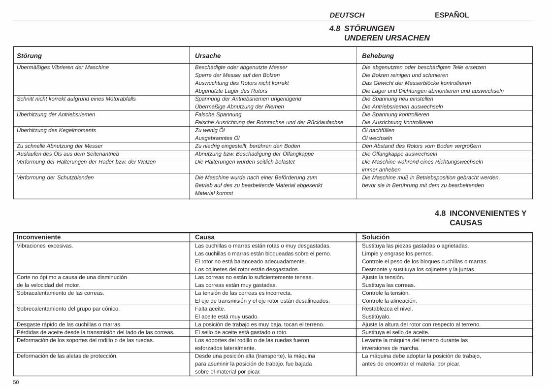
ITALIANO ENGLISH FRANÇAIS ESPAÑOLDEUTSCH
50
Inconveniente Causa SoluciónVibraciones excesivas. Las cuchillas o marras están rotas o muy desgastadas. Sustituya las piezas gastadas o agrietadas.
Las cuchillas o marras están bloqueadas sobre el perno. Limpie y engrase los pernos.El rotor no está balanceado adecuadamente. Controle el peso de los bloques cuchillas o marras.Los cojinetes del rotor están desgastados. Desmonte y sustituya los cojinetes y la juntas.
Corte no óptimo a causa de una disminución Las correas no están lo suficientemente tensas. Ajuste la tensión.de la velocidad del motor. Las correas están muy gastadas. Sustituya las correas.Sobracalentamiento de las correas. La tensión de las correas es incorrecta. Controle la tensión.
El eje de transmisión y el eje rotor están desalineados. Controle la alineación.Sobrecalentamiento del grupo par cónico. Falta aceite. Restablezca el nivel.
El aceite está muy usado. Sustitúyalo.Desgaste rápido de las cuchillas o marras. La posición de trabajo es muy baja, tocan el terreno. Ajuste la altura del rotor con respecto al terreno.Pérdidas de aceite desde la transmisión del lado de las correas. El sello de aceite está gastado o roto. Sustituya el sello de aceite.Deformación de los soportes del rodillo o de las ruedas. Los soportes del rodillo o de las ruedas fueron Levante la máquina del terreno durante las
esforzados lateralmente. inversiones de marcha.Deformación de las aletas de protección. Desde una posición alta (transporte), la máquina La máquina debe adoptar la posición de trabajo,
para asuminir la posición de trabajo, fue bajada antes de encontrar el material por picar.sobre el material por picar.
4.8 INCONVENIENTES YCAUSAS
Störung Ursache Behebung
Übermäßiges Vibrieren der Maschine Beschädigte oder abgenutzte Messer Die abgenutzten oder beschädigten Teile ersetzenSperre der Messer auf den Bolzen Die Bolzen reinigen und schmierenAuswuchtung des Rotors nicht korrekt Das Gewicht der Messerblöcke kontrollierenAbgenutzte Lager des Rotors Die Lager und Dichtungen abmontieren und auswechseln
Schnitt nicht korrekt aufgrund eines Motorabfalls Spannung der Antriebsriemen ungenügend Die Spannung neu einstellenÜbermäßige Abnutzung der Riemen Die Antriebsriemen auswechseln
Überhitzung der Antriebsriemen Falsche Spannung Die Spannung kontrollierenFalsche Ausrichtung der Rotorachse und der Rücklaufachse Die Ausrichtung kontrollieren
Überhitzung des Kegelmoments Zu wenig Öl Öl nachfüllenAusgebranntes Öl Öl wechseln
Zu schnelle Abnutzung der Messer Zu niedrig eingestellt, berühren den Boden Den Abstand des Rotors vom Boden vergrößernAuslaufen des Öls aus dem Seitenantrieb Abnutzung bzw. Beschädigung der Ölfangkappe Die Ölfangkappe auswechselnVerformung der Halterungen der Räder bzw. der Walzen Die Halterungen wurden seitlich belastet Die Maschine während eines Richtungswechseln
immer anhebenVerformung der Schutzblenden Die Maschine wurde nach einer Beförderung zum Die Maschine muß in Betriebsposition gebracht werden,
Betrieb auf des zu bearbeitende Material abgesenkt bevor sie in Berührung mit dem zu bearbeitendenMaterial kommt
4.8 STÖRUNGENUNDEREN URSACHEN
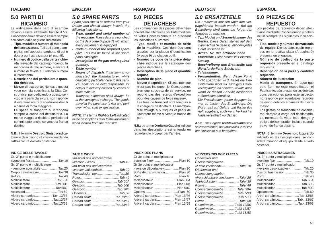
51
ITALIANO ENGLISH FRANÇAIS ESPAÑOLDEUTSCH
5.0 PARTI DI RICAMBIOLe ordinazioni delle parti di ricambio devono essere effettuate tramite il Vs. Concessionario e devono essere sempre corredate dalle seguenti indicazioni:- Tipo, modello e numero di matricola
dell’attrezzatura. Tali dati sono stam-pigliati nell’apposita targhetta di cui è dotata ogni attrezzatura (A pag. 9).
- Numero di codice della parte richie-sta rilevabile dal catalogo ricambi. In mancanza di tale numero, elencare il numero di tavola e il relativo numero di riferimento.
- Descrizione del particolare e quan-tità richiesta.
- Mezzo di trasporto. Nel caso questa voce non sia specifi cata, la Ditta Co-struttrice, pur dedicando a questo ser-vizio una particolare cura, non risponde di eventuali ritardi di spedizione dovuti a cause di forza maggiore.
Le spese di trasporto si intendono sempre a carico del destinatario. La merce viaggia a rischio e pericolo del committente anche se venduta franco destino.
N.B.: Il termine Destro o Sinistro indica-to nelle descrizioni, và inteso guardando l’attrezzatura dal lato posteriore
INDICE DELLE TAVOLEGr. 3° punto e moltiplicatore«versione fi ssa»........................... Tav.10Gr. 3° punto e moltiplicatore«versione spostabile».................. Tav.20Corpo trasmissione...................... Tav.30Rotore.......................................... Tav.40Moltiplicatore.............................Tav.50AMoltiplicatore ........................... Tav.50BMoltiplicatore ........................... Tav.50CAccessori ....................................Tav.60Albero cardanico...................Tav. 13/66Albero cardanico....................Tav.13/67Albero cardanico....................Tav.13/68
5.0 SPARE PARTSSpare parts should be ordered from your Dealer and should always include the following indications:- Type, model and serial number of
the machine. These data are punched on the data plate (A page 7) with which every implement is equipped.
- Code number of the required spare part. This will be found in the spare parts catalogue.
- Description of the part and required quantity.
- Table number- Means of dispatch. If this item is not
indicated, the Manufacturer, while dedicating particular care to this serv-ice, shall not be held responsible for delays in delivery caused by cases of force majeure.
Transport expenses shall always be at the consignee’s charge. The goods travel at the purchaser’s risk and peril even when sold ex destination.
NOTE: The terms Right or Left indicated in the descriptions refer to the implement when viewed from the rear side.
TABLE INDEX3rd-point unit and overdrive«version Fixed»........................... Tab.103rd-point unit and overdrive«version adjustable»................... Tab.20Transmission box........................Tab.30Rotor........................................... Tab.40Gearbox.................................... Tab.50AGearbox.................................... Tab.50BGearbox.................................... Tab.50COptionals.....................................Tab.60Cardan shaft...........................Tab.13/66Cardan shaft...........................Tab.13/67Cardan shaft...........................Tab.13/68
5.0 ERSATZTEILEDie Ersatzteile müssen über den Ver-tragshänder bestellt werden. Bei der Bestellung sind stets die folgenden Angaben zu machen:- Typ, Modell und Serien-Nummer des
Geräts. Diese Daten stehen auf dem Typenschild (A Seite 9), mit dem jedes Gerät versehen ist.
- Artikel Nr. der erforderlichen Ersatzteile. Diese stehen im Ersatzteil-Katalog.
- Beschreibung des Ersatzteils und die erforderliche Stückzahl.
- Tafelnummer.- Versandmittel. Wenn dieser Punkt
nicht spezifi ziert wird, haftet die Her-stellerfi rma nicht für etwaigen Liefer-verzug aufgrund höherer Gewalt, auch wenn er diesen Service besonders aufmerksam abwickelt.
Die Frachtkosten gehen dagegen im-mer zu Lasten des Empfängers. Die Ware reist auf Gefahr und Risiko des Auftraggebers, auch wenn Verkauf frei Haus vereinbart worden ist.
Anm.: Die Begriffe rechts und links sind so zu verstehen, daß man das Gerät von der Rückseite aus betrachtet.
VERZEICHNIS DER TAFELNOberlenker und Übersetzungetriebe«Feste versionen» ...................Tafel 10Oberlenker und Übersetzungetriebe«Verschiebbare versionen». ....Tafel 20Antriebskasten .........................Tafel 30Rotors ......................................Tafel 40Übersetzungetriebe .............. Tafel 50AÜbersetzungetriebe .............. Tafel 50BÜbersetzungetriebe .............. Tafel 50CExtras ......................................Tafel 60Gelenkwelle ........................Tafel 13/66Gelenkwelle ........................Tafel 13/67Gelenkwelle ........................Tafel 13/68
5.0 PIECES DÉTACHÉESLes commandes des pièces détachées doivent être effectuées par l’intermédiaire de votre Concessionnaire en précisant les indications suivantes:- Type, modèle et numéro de série
de la machine. Ces données sont gravées sur la plaque d’identifi cation (A page 9) de chaque outil.
- Numéro de code de la pièce déta-chée indiqué sur le catalogue des pièces détachées.
- Description de la pièce et quantité requise.
- Numéro de plan.- Moyen d’expédition. Si cette rubrique
n’est pas indiquée, le Constructeur, bien que soucieux de ce service, ne répond pas des retards d’expédition pour des causes de force majeure.
Les frais de transport sont toujours à la charge du destinataire. La marchan-dise voyage aux risques et périls de l’acheteur même si vendue franco de port.
N.B.: Le terme Droite ou Gauche indiqué dans les descriptions est entendu en regardant le broyeur par l’arrière.
INDEX DES PLANSGr 3e point et moltiplicateur«version fi xe» ...........................Plan 10Gr 3e point et moltiplicateur«version déportable» ................Plan 20Boîte de transmission ...............Plan 30Rotor.......................................... Plan 40Moltiplicateur........................... Plan 50AMoltiplicateur ..........................Plan 50BMoltiplicateur ......................... Plan 50COptions ....................................Plan 60Arbre à cardans ...................Plan 13/66Arbre à cardans ...................Plan 13/67Arbre à cardans ...................Plan 13/68
5.0 PIEZAS DE REPUESTOLos pedidos de repuestos deben efec-tuarse mediante Concesionario y deben incluir siempre las siguientes indicacio-nes:- Tipo, modelo y número de matrícula
del equipo. Dichos datos están impre-sos en la relativa placa (A pagína 9) presente en el equipo.
- Número de código de la parte requerida presente en el catálogo repuestos.
- Descripción de la pieza y cantidad requerida.
- Número de ilustracion- Medio de transporte. En caso que
este ítem no esté especificado, el Fabricante, aún prestando las debidas consideraciones para este aspecto, no responde por eventuales retardos de envío debidos a causas de fuerza mayor.
Los gastos de transporte se conside-ran siempre a cargo del destinatario. La mercadería viaja bajo riesgo y peligro del comprador, incluso cuando se vende franco destino.
NOTA: El termino Derecho o Izquierdo indicado en las descripciones, se con-sidera mirando el equipo desde el lado posterior.
INDICE ILUSTRACIONESGr. 3° punto y multiplicador«version fi ja». .............................Tab.10Gr. 3° punto y multiplicador«version desplazables». .............Tab.20Cuerpo trasmission.....................Tab.30Rotor. ..........................................Tab.40Multiplicador..............................Tab.50AMultiplicador .............................Tab.50BMultiplicador ............................ Tab.50COpcionales..................................Tab.60Arbol cardánico......................Tab 13/66Arbol cardánico....................Tab. 13/67Arbol cardánico.....................Tab. 13/68


PARTI DI RICAMBIOSPARE PARTSPIECES DÉTACHÉESERSATZTEILEPIEZAS DE REPUESTO
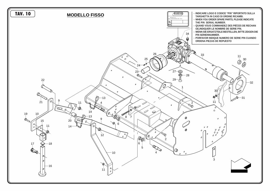
MODELLO FISSO
21
22
9
19 10
15
11
17 18
16
20
14
13
11
12
9
11
10
14
13
4
5
6
8 7
6
5
4
2
3
2
1
29
282723
24
25
26
34
33 1130
32
31
30
11
35011 CAMPODARSEGO (PD) - ITALY
MASCHIO S.p.A.
TAV. 10 - INDICARE LOGO E CODICE “P/N” RIPORTATO SULLA TARGHETTA IN CASO DI ORDINE RICAMBI.- WHEN YOU ORDER SPARE PARTS, PLEASE INDICATE THE P/N SERIAL NUMBER.- QUAND VOUS COMMANDEZ DES PIÈCES DE RECHAN GE,INDIQUER LE NOMBRE DE SERIE P/N.- WENN SIE ERSATZTEILE BESTELLEN, BITTE ZEIGEN DIE P/N SERIENNUMMER.- PORFAVOR INDIQUE NUMERO DE SERIE P/N CUANDO ORDENA PIEZAS DE REPUESTO

POS CODICE DESCRIZIONE DESCRIPTION DESCRIPTION BENENNUNG DESCRIPCION
1 M28410511 COMP.TELAIO FISSO BCA 100 COMPLETE FRAME CHASSIS COMPL. KOMPL. RAHMEN TELAR COMPL. M28412511 COMP.TELAIO FISSO BCA 120 COMPLETE FRAME CHASSIS COMPL. KOMPL. RAHMEN TELAR COMPL.2 F01010291 VITE M12X1,25X 40 5740 8.8 ZG BOLT M 12X40 VIS M 12X40 SCHRAUBE M 12X40 TORNILLO M 12X403 T16005012 CHIUSURA LATERALE V REAR LATERAL PANEL CAPOT ARRIERE LATERAL HINTERE BLECH PLANCHA LATERALE4 F20100052 PERNO D=22 L=160 ZG PIN FOR BAR LINKAGE GOUJON ATTELAGE BARRE VERB.BOLZEN SCHUTZHOLM PERNO ATAQUE BARRA5 F01480189 ROSET.GROWER M24 ZGP EXTRA P. GROWER WASHER D.24 RONDELLE GROWER D.24 SCHEIBE GROWER D.24 ARANDELA GROWER D.246 F01200377 DADO NORM. M24X2 5588 6S ZG NUT M24X2 ECROU M24X2 MUTTER M24X2 DADO M24X27 F01200268 DADO M10X1,25 U5588 6S ZG NUT M10X1,25 ECROU M10X1,25 MUTTER M10X1,25 DADO M10X1,258 F01010264 VITE M10X1,25X 70 5740 8.8 BR BOLT M 10X1,25X70 VIS M 10X1,25X70 SCHRAUBE M 10X1,25X70 TORNILLO M 10X1,25X709 M28400537 PIATTO POSTERIORE DX 3°PUNTO REAR SUPPORT 3RD POINT BARRE HINTERSTANGE 3. PUNKT ASTA POSTERIOR 3 PUNTO10 T23009843 PUNTONE 3°PUNTO 3RD POINT SUPPORT BARRE HINTERSTANGE 3.PUNKT ASTA 3 PUNTO11 F01220047 DADO METAL M12X1,25 D980 6S ZG SELF LOCKING NUT M12X1,25 980V ECROU AUTOBL. M12X1,25 980-V SELBSTSP.MUTT. M12X1,25 980-V DADO AUTOBL. M12X1,25 980-V12 F01220070 DADO METAL M16X1,5 D980 6S ZG SELF LOCKING NUT M16X1,5 980V ECROU AUTOBL. M16X1,5 980-V SELBSTSP.MUTT. M16X1,5 980-V DADO AUTOBL. M16X1,5 980-V13 F02200529 SPINOTTO A SCATTO D11 ZGP SPLIT PIN D.11 GOUPILLE D.11 SPLINT D.11 RODETE D.1114 M63112581 ASSIEME CATENELLA L.333 ZPG CHAIN CHAINE KETTE CADENA15 T23005300 ATTACCO PIEDINO SUPPORT SUPPORT HALTER SOPORTE16 M48000594 COMP. PIEDINO SUPPORTO FEET SUPPORTING ROTARY CULTIV. SUPPORT FRAISE FRASE STANDER SOPORTE FRESADORA17 F02200562 SPINOTTO D.8 L=70 ZG SPLIT PIN GOUPILLE BOLZEN PERNO18 F05100025 TAPPO AD ALETTE 35X35 PLT NERO PLUG BOUCHON FERMETURE VERSCHLUSSPFROPFEN TAPONCLAUSURA19 F01010055 VITE M12X1,25X 50 5738 8.8 ZG BOLT M 12X1,25X50 VIS M 12X1,25X50 SCHRAUBE M 12X1,25X50 TORNILLO M 12X1,25X5020 M40200515 BOCCOLA UNIONE 3 P. BUSH 3 POINT BAGUE 3EME POINT BUECHSE DREIPUNKT BRUJULA 3 PUNTO21 F01010128 VITE M16X1,5 X130 5738 8.8 ZG BOLT M 16X1,5X130 VIS M 16X1,5X130 SCHRAUBE M 16X1,5X130 TORNILLO M 16X1,5X13022 F20100035 PERNO PER 3° PUNTO RAPIDO ZPG PIN GOUJON BOLZEN PERNO23 M38100146 MANICOTTO PROTEZIONE PDF 1”3/8 P.T.O. PROTECTION MANCHON DE PROTECTION P.T.O. ZAPFWELLENSCHUTZ P.T.O. MANGUITO PROTECCION P.T.O.24 F01020432 VITE M 8X1,25X 16 5739 8.8 ZG BOLT M 8X16 VIS M 8X16 SCHRAUBE M 8X16 TORNILLO M 8X1625 F01410051 ROSET.PER T.E.8,4X17 ZP 6592 PLANE WASHER D.8 RONDELLE D.8 SCHEIBE D.8 ARANDELA D.826 F05150403 CUFFIA PROTEZ,CARDANO CARDAN PROTECTION PROTECTION CARDAN GELENKWELLENSCHUTZ PROTECCION CARDANICO27 F01500011 ROS.M12 FASCIA LAR.DIN6340 ZG WASHER D. 12 RONDELLE D.12 SCHEIBE D.12 ARANDELA D.1228 F01480123 ROSET.GROWER M12 ZGP EXTRA P. GROWER WASHER D.12 RONDELLE GROWER D.12 SCHEIBE GROWER D.12 ARANDELA GROWER D.1229 F01010283 VITE TE M12X30 BOLT M 12X30 VIS M 12X30 SCHRAUBE M 12X30 TORNILLO M 12X3030 F01410076 ROS.M12 13X 24X2,5 U6592 ZG PLANE WASHER D.12 RONDELLE D.12 SCHEIBE D.12 ARANDELA D.1231 F01010296 VITE M12X1,25X 65 5738 BOLT M 12X1,25X65 VIS M 12X1,25X65 SCHRAUBE M 12X1,25X65 TORNILLO M 12X1,25X6532 T16005526 SUPPORTO TENDICINGHIA BELT STRETCHER SUPPORT TENDEUR DE COURROIE HALTERUNG SOPORTE33 T24121200 SCATOLA*CAM.+PROL.L=500 BCA GEARBOX BOITE DE VITESSE WECHSELGETRIEBEGEHAEUSE CAJA CAMBIO34 F03150718 TAPPO 3/8” GAS CON SFIATO OIL BREATHER PLUG BOUCHON D’HUILE SOUPIRAIL OELENTLUEFTERSTOPFEN TAPON ACEITE
TAV. 10
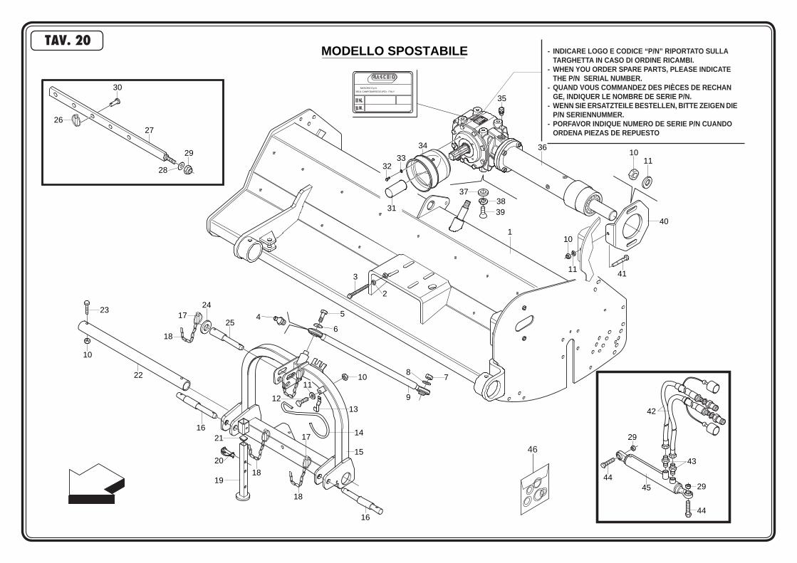
MODELLO SPOSTABILE
30
29
28
2726
1
2
3
4 5
6
11
1312
1417
15
16
18
18
21
20
19
16
22
10
23
25
2417
18
42
43
44
44
45 29
29
10 78
9
3233
31
34
37
3938
35
3610
11
11
10
41
40
35011 CAMPODARSEGO (PD) - ITALY
MASCHIO S.p.A.
46
- INDICARE LOGO E CODICE “P/N” RIPORTATO SULLA TARGHETTA IN CASO DI ORDINE RICAMBI.- WHEN YOU ORDER SPARE PARTS, PLEASE INDICATE THE P/N SERIAL NUMBER.- QUAND VOUS COMMANDEZ DES PIÈCES DE RECHAN GE, INDIQUER LE NOMBRE DE SERIE P/N.- WENN SIE ERSATZTEILE BESTELLEN, BITTE ZEIGEN DIE P/N SERIENNUMMER.- PORFAVOR INDIQUE NUMERO DE SERIE P/N CUANDO ORDENA PIEZAS DE REPUESTO
TAV. 20

POS CODICE DESCRIZIONE DESCRIPTION DESCRIPTION BENENNUNG DESCRIPCION
1 M28414510 COMP.TELAIO SPOSTABILE BCA 140 COMPLETE FRAME 140 CHASSIS COMPL. 140 KOMPL. RAHMEN 140 TELAR COMPL. 140 M28416510 COMP.TELAIO SPOSTABILE BCA 160 COMPLETE FRAME 160 CHASSIS COMPL. 160 KOMPL. RAHMEN 160 TELAR COMPL. 160 M28418510 COMP.TELAIO SPOSTABILE BCA 180 COMPLETE FRAME 180 CHASSIS COMPL. 180 KOMPL. RAHMEN 180 TELAR COMPL. 180 M28420510 COMP.TELAIO SPOSTABILE BCA 180 COMPLETE FRAME 180 CHASSIS COMPL. 180 KOMPL. RAHMEN 180 TELAR COMPL. 1802 F01200268 DADO M10X1,25 U5588 6S ZG NUT M10X1,25 ECROU M10X1,25 MUTTER M10X1,25 DADO M10X1,253 F01010264 VITE M10X1,25X 70 5740 8.8 BR BOLT M 10X1,25X70 VIS M 10X1,25X70 SCHRAUBE M 10X1,25X70 TORNILLO M 10X1,25X704 F01100048 ING.M 8X1,25 7663A 9SMNPB28 ZG SPHERE NIPPLE M8X 1,25 A GRAISSEUR A BILLES M8 X 1-25 A KUGELFETTBsCHSE M8 X 1-25 A ENGRAS. DE ESFERAS M8 X 1-25 A5 F01010244 VITE M10X1,25X 25 5740 8.8 ZG BOLT M 10X1,25X25 VIS M 10X1,25X25 SCHRAUBE M 10X1,25X25 TORNILLO M 10X1,25X256 F01500010 ROS. 10,5X28X4 D6340 C50 ZG WASHER 10,5X28X4 RONDELLE 10,5X28X4 SCHEIBE 10,5X28X4 ARANDELA 10,5X28X47 F01220093 DADO METAL M20X1,5 D980 6S ZG SELF LOCKING NUT M20X1,5 980V ECROU AUTOBL. M20X1,5 980-V SELBSTSP.MUTT. M20X1,5 980-V DADO AUTOBL. M20X1,5 980-V8 F01410124 ROSETTA 20X34 UNI 6593-69 ZPG PLANE WASHER D. 20 RONDELLE D. 20 SCHEIBE D.20 ARANDELLA D.209 T24009611 TIRANTE 3° PUNTO ZPG 3RD POINT STRETCHER TENDEUR 3EME POINT 3.PUNKT ZUGSTANGE TENSOR TERCER PUNTO10 F01220047 DADO METAL M12X1,25 D980 6S ZG SELF LOCKING NUT M12X1,25 980V ECROU AUTOBL. M12X1,25 980-V SELBSTSP.MUTT. M12X1,25 980-V DADO AUTOBL. M12X1,25 980-V11 F01410076 ROS.M12 13X 24X2,5 U6592 ZG PLANE WASHER D.12 RONDELLE D.12 SCHEIBE D.12 ARANDELA D.1212 F01010279 VITE M12X1,25X 20 5740 8.8 ZG BOLT M 12X1,25X20 VIS M 12X1,25X20 SCHRAUBE M 12X1,25X20 TORNILLO M 12X1,25X2013 F20120401 FASCETTA FERMO GANCIO CARDANO LOCK ARRET BLOCKIERUNG PARADO14 F20120400 GANCIO SOSTEGNO CARDANO SHAFT HOOK SUPPORT CARDAN GELENKWELLE - HACKEN SOPORTE CARDAN15 M28400529 TERZO PUNTO SPOSTABILE 3RD POINT 3EME POINT 3. PUNKT TERCER PUNTO16 F20100053 PERNO D22-28-22 L=40-70-100 PIN FOR BAR LINKAGE GOUJON ATTELAGE BARRE VERB.BOLZEN SCHUTZHOLM PERNO ATAQUE BARRA17 F02200529 SPINOTTO A SCATTO D11 ZGP SPLIT PIN D.11 GOUPILLE D.11 SPLINT D.11 RODETE D.1118 M63112581 ASSIEME CATENELLA L.333 ZPG CHAIN CHAINE KETTE CADENA19 M48000594 COMP. PIEDINO SUPPORTO FEET SUPPORTING ROTARY CULTIV. SUPPORT FRAISE FRASE STANDER SOPORTE FRESADORA20 F02200562 SPINOTTO D.8 L=70 ZG SPLIT PIN GOUPILLE BOLZEN PERNO21 F05100025 TAPPO AD ALETTE 35X35 PLT NERO PLUG BOUCHON FERMETURE VERSCHLUSSPFROPFEN TAPONCLAUSURA22 M24416533 ASTA SCORRIMENTO L=1507 SLIDING ROD L=1507 TIGE DE GLISSEMENT L=1507 GLEITSTANGE L=1507 BARRA DESLIZAMIENTO L=1507 M24418533 ASTA SCORRIMENTO L=1420 SLIDING ROD L=1420 TIGE DE GLISSEMENT L=1420 GLEITSTANGE L=1420 BARRA DESLIZAMIENTO L=142023 F01010288 VITE M12X1,25X 35 5740 8.8 BR BOLT M 12X1,25X35 VIS M 12X1,25X35 SCHRAUBE M 12X1,25X35 TORNILLO M 12X1,25X3524 F01410112 ROSET.PER T.E.19X34 ZGP 6592 PLANE WASHER D.18 RONDELLE D.18 SCHEIBE D.18 ARANDELA D.1825 F20100037 PERNO D=25 D=19 L=210 PIN FOR BAR LINKAGE GOUJON ATTELAGE BARRE VERB.BOLZEN SCHUTZHOLM PERNO ATAQUE BARRA26 F02200485 COPPIGLIA A SCATTO DIAM.6 SPLIT PIN D.6 GOUPILLE D.6 SPLINT D.6 RODETE D.627 M28400565 COMP.ASTA SCORR.MECCANICA 200 SLIDING ROD TIGE DE GLISSEMENT GLEITSTANGE BARRA DESLIZAMIENTO28 F01480145 ROS.G 17X29 X 5 EX.C70 ZG GROWER WASHER D.16 RONDELLE GROWER D.16 SCHEIBE GROWER D.16 ARANDELA GROWER D.1629 F01220070 DADO METAL M16X1,5 D980 6S ZG SELF LOCKING NUT M16X1,5 980V ECROU AUTOBL. M16X1,5 980-V SELBSTSP.MUTT. M16X1,5 980-V DADO AUTOBL. M16X1,5 980-V30 M38100573 PERNO DI REGOLAZIONE ZGPD PIN GOUJON BOLZEN PERNO31 M38100146 MANICOTTO PROTEZIONE PDF 1”3/8 P.T.O. PROTECTION MANCHON DE PROTECTION P.T.O. ZAPFWELLENSCHUTZ P.T.O. MANGUITO PROTECCION P.T.O.32 F01020432 VITE M 8X1,25X 16 5739 8.8 ZG BOLT M 8X16 VIS M 8X16 SCHRAUBE M 8X16 TORNILLO M 8X1633 F01410051 ROSET.PER T.E.8,4X17 ZP 6592 PLANE WASHER D.8 RONDELLE D.8 SCHEIBE D.8 ARANDELA D.834 F05150403 CUFFIA PROTEZ,CARDANO CARDAN PROTECTION PROTECTION CARDAN GELENKWELLENSCHUTZ PROTECCION CARDANICO35 F03150718 TAPPO 3/8” GAS CON SFIATO OIL BREATHER PLUG BOUCHON D’HUILE SOUPIRAIL OELENTLUEFTERSTOPFEN TAPON ACEITE36 T24151200 SCATOLA*CAM.+PROL.L=615 GEARBOX BOITE DE VITESSE WECHSELGETRIEBEGEHAEUSE CAJA CAMBIO T24191200 SCATOLA*CAM.+PROL.L=780 GEARBOX BOITE DE VITESSE WECHSELGETRIEBEGEHAEUSE CAJA CAMBIO37 F01500011 ROS.M12 FASCIA LAR.DIN6340 ZG WASHER D. 12 RONDELLE D.12 SCHEIBE D.12 ARANDELA D.1238 F01480123 ROSET.GROWER M12 ZGP EXTRA P. GROWER WASHER D.12 RONDELLE GROWER D.12 SCHEIBE GROWER D.12 ARANDELA GROWER D.1239 F01010283 VITE TE M12X30 BOLT M 12X30 VIS M 12X30 SCHRAUBE M 12X30 TORNILLO M 12X3040 T16005526 SUPPORTO TENDICINGHIA BELT STRETCHER SUPPORT TENDEUR DE COURROIE HALTERUNG SOPORTE41 F01010296 VITE M12X1,25X 65 5738 BOLT M 12X1,25X65 VIS M 12X1,25X65 SCHRAUBE M 12X1,25X65 TORNILLO M 12X1,25X6542 M70100568 COMP. TUBAZIONE IDR. L=2800 HYDRAULIC TUBE TUBE HYDRAUL. HYDRAUL. ROHR TUBO HYDRAULICO43 F03150310 NIPPLO 3/8 - 1/4 NIPPLE GALV.CYL.MALE3/8-1/4 ZN NIPPLE MALE CYL.3/8-1/4 ZN NIPPELZYL.3/8-1/4 ZN NIPLE MACHO CIL.3/8-1/4 ZN44 F01010346 VITE M16X1,5X 60 U5740 8.8 ZG BOLT M16X1,5X60 VIS M16X1,5X60 SCHRAUBE M16X1,5X60 TORNILLO M16X1,5X6045 T23169911 CILINDRO IDRAULICO BC160 HYDRAULIC JACK BC160 CILINDRE HYDRAULIQUE BC160 HYDR. ZILINDER BC160 PISTON HYDRAULICO BC160
TAV. 20
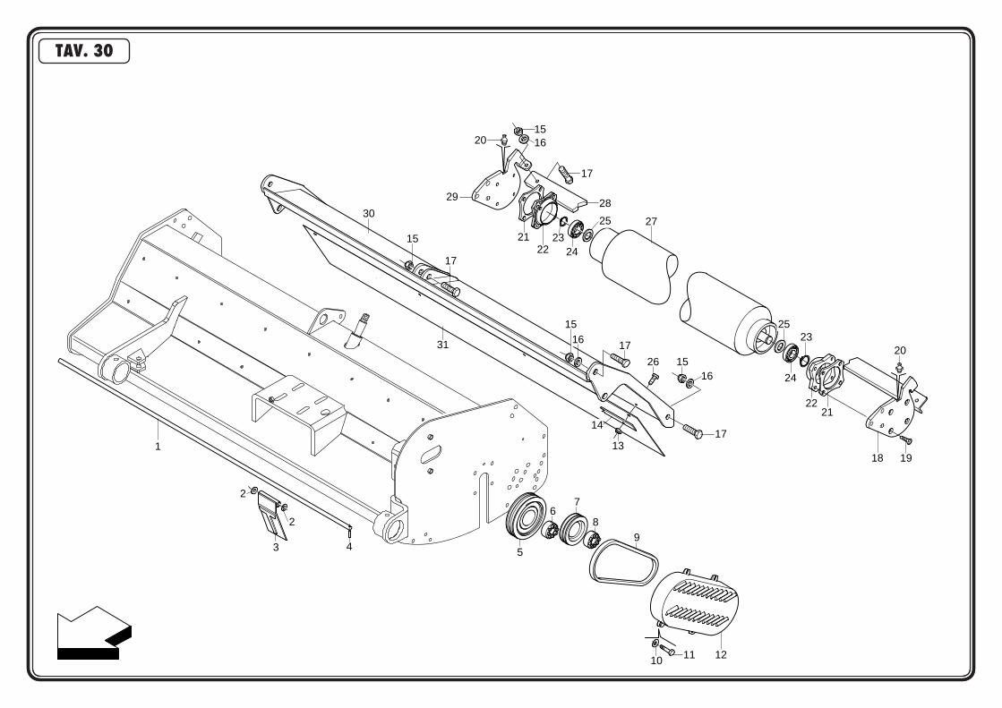
1
3
2
2
4 5
67
89
10 11 12
14
13
31
1516
17
26
171615
27
17
15
30
29
201516
17
28
2122
2221
2325
24
20
1918
2423
25
TAV. 30

POS CODICE DESCRIZIONE DESCRIPTION DESCRIPTION BENENNUNG DESCRIPCION TAV. 301 T21095016 ASTA PER BANDELLE E COPERCHIO PIPE TUYAU ROHR TUBO T21115016 ASTA PER BANDELLE E COPERCHIO PIPE TUYAU ROHR TUBO T21135016 ASTA PER BANDELLE E COPERCHIO PIPE TUYAU ROHR TUBO T21155016 ASTA PER BANDELLE E COPERCHIO PIPE TUYAU ROHR TUBO T21185016 ASTA PER BANDELLE BCA180-BL170 PIN GOUJON BOLZEN PERNO T21195016 ASTA PER BANDELLE BL190 PIN GOUJON BOLZEN PERNO2 F01410100 ROSET.PER T.E.17X30 UNI6592 PLANE WASHER D.16 RONDELLE D.16 SCHEIBE D.16 ARANDELA D.163 M24400518 BANDELLA PROTEZ. 93X170 ZG PROTECTION BAR BANDE PROTECTION SCHUTZWORNE ALETA PROTECCION4 F02100114 SPINA ELASTICA 6X30 UNI 6873 ELASTIC PIN 6X30 GOUJON ELASTIQUE 6X30 SPANNHUELSE 6X30 ESPINA ELASTICA 6X305 T23003002 PULEGGIA MOTRICE DP=225 DRIVING PULLEY POULIE TIRANTE ZIEHEN RIEMEN ROLDANA DE TIRAR T30003002 PULEGGIA ROTORE D=224 4V DRIVING PULLEY POULIE TIRANTE ZIEHEN RIEMEN ROLDANA DE TIRAR6 F06060038 CALETTATORE AUTOCENTR.40X80 SELF LOCKING KEYNG 40X80 EMBOITAGE AUOBL. 40X80 SELBSTPERR.VERKEILEN 40X80 ENSAMBLADURA AUTOBL. 40X807 T22003001 PULEGGIA ROTORE DP=160 DRIVING PULLEY POULIE TIRANTE ZIEHEN RIEMEN ROLDANA DE TIRAR T16003005 PULEGGIA DP=160 A 4 GOLE PULLEY POULIE SCHEIBE ROLDANA8 F06060037 CALETTATORE AUTOCENTR.35X80 SELF LOCKING KEYNG 35X80 EMBOITAGE AUOBL. 35X80 SELBSTPERR.VERKEILEN 35X80 ENSAMBLADURA AUTOBL. 35X809 F06010039 CINGHIA SPBX L=1320 BELT COURROIE SCHAUBE CORREA10 F01410064 ROSET.PER T.E.10,5X21 ZPG 6592 WASHER 10,5X21 RONDELLE 10,5X21 SCHEIBE 10,5X21 ARANDELA 10,5X2111 F01010244 VITE M10X1,25X 25 5740 8.8 ZG BOLT M 10X1,25X25 VIS M 10X1,25X25 SCHRAUBE M 10X1,25X25 TORNILLO M 10X1,25X2512 T16003150 COMP.CARTER CARTER CARTER GEHAEUSE CARTER13 F01220022 DADO METAL M 8X1,25 D980 6S ZG SELF LOCKING NUT M8X1,25 980V ECROU AUTOBL. M8X1,25 980-V SELBSTSP.MUTT. M8X1,25 980-V DADO AUTOBL. M8X1,25 980-V14 M07400953 PIATTO PER ATTACCO GOMMA PLATE PLAT PLATTE PLATO15 F01220047 DADO METAL M12X1,25 D980 6S ZG SELF LOCKING NUT M12X1,25 980V ECROU AUTOBL. M12X1,25 980-V SELBSTSP.MUTT. M12X1,25 980-V DADO AUTOBL. M12X1,25 980-V16 F01410076 ROS.M12 13X 24X2,5 U6592 ZG PLANE WASHER D.12 RONDELLE D.12 SCHEIBE D.12 ARANDELA D.1217 F01010288 VITE M12X1,25X 35 5740 8.8 BR BOLT M 12X1,25X35 VIS M 12X1,25X35 SCHRAUBE M 12X1,25X35 TORNILLO M 12X1,25X3518 M22400603 SUPPORTO RULLO SX LEFT ROLLER SUPPORT SUPPORT ROULEAU GAUCHE SCHUTZHOLM WALZE LINKS SOPORTE RODILLO IZQUIERDO19 M36200542 VITE M12X1,25X 30 SPEC.10,9 BR BOLT M 12X1,25X30 VIS M 12X1,25X30 SCHRAUBE M 12X1,25X30 TORNILLO M 12X1,25X3020 F01100048 ING.M 8X1,25 7663A 9SMNPB28 ZG SPHERE NIPPLE M8X 1,25 A GRAISSEUR A BILLES M8 X 1-25 A KUGELFETTBsCHSE M8 X 1-25 A ENGRAS. DE ESFERAS M8 X 1-25 A21 M22400606 DISTANZIALE RULLO SPACER ENTRETOISE DISTANZSTUECK DISTANCIADOR22 M38100992 SUPPORTO RULLO OSCILL.DI TESTA BEARING SUPPORT FLANGE FLASQUE SUPPORT ROULEMENT LAGERFLANSCH BRIDA SOPORTE COJINETE23 F02050168 ANEL.EL.PER EST.DE40 UNI7435 SEEGER RING D.40 BAGUE SEEGER D.40 SEEGERRING D.40 ANILLO SEEGER D.4024 F04010184 CUSC.DE SFERICO 76208 A2KS FAG BEARING 6208 SEE ROULEMENT 6208 SEE LAGER 6208 SEE COJINETE 6208 SEE25 M38100990 GUARNIZIONE ELASTICA GASKET JOINT DICHTUNG JUNTA26 F01020436 VITE M 8X1,25X 20 5739 8.8 ZG BOLT M 8X20 VIS M 8X20 SCHRAUBE M 8X20 TORNILLO M 8X2027 M22410600 RULLO VITA 100 ROLLER VITA 100 ROULEAU VITA 100 WALZE VITA 100 RODILLO VITA 100 M22412600 RULLO VITA 120 ROLLER VITA 120 ROULEAU VITA 120 WALZE VITA 120 RODILLO VITA 120 M22414600 RULLO VITA 140 ROLLER VITA 140 ROULEAU VITA 140 WALZE VITA 140 RODILLO VITA 140 M22415600 RULLO VITA 160 ROLLER VITA 160 ROULEAU VITA 160 WALZE VITA 160 RODILLO VITA 160 M22417600 RULLO VITA 170 ROLLER VITA 170 ROULEAU VITA 170 WALZE VITA 170 RODILLO VITA 170 M22419600 RULLO VITA 190 ROLLER VITA 190 ROULEAU VITA 190 WALZE VITA 190 RODILLO VITA 19028 M22410602 RASCHIA FANGO BV 100 ZG MUD SCRAPER BV 100 DECROTTOIR POUR BOUE BV 100 ABSTREIFER FUR SCHLAMM BV 100 RASCADOR PARA FANGO BV 100 M22412602 RASCHIA FANGO BV 120 ZG MUD SCRAPER BV 120 DECROTTOIR POUR BOUE BV 120 ABSTREIFER FUR SCHLAMM BV 120 RASCADOR PARA FANGO BV 120 M22414602 RASCHIA FANGO BV 140 ZG MUD SCRAPER BV 140 DECROTTOIR POUR BOUE BV 140 ABSTREIFER FUR SCHLAMM BV 140 RASCADOR PARA FANGO BV 140 M22416602 RASCHIA FANGO BV 160 ZG MUD SCRAPER BV 160 DECROTTOIR POUR BOUE BV 160 ABSTREIFER FUR SCHLAMM BV 160 RASCADOR PARA FANGO BV 160 M22417602 RASCHIA FANGO BV 170 ZG MUD SCRAPER BV 170 DECROTTOIR POUR BOUE BV 170 ABSTREIFER FUR SCHLAMM BV 170 RASCADOR PARA FANGO BV 170 M22419602 RASCHIA FANGO BV 190 ZG MUD SCRAPER BV 190 DECROTTOIR POUR BOUE BV 190 ABSTREIFER FUR SCHLAMM BV 190 RASCADOR PARA FANGO BV 19029 M22400604 SUPPORTO RULLO DX RIGHT ROLLER SUPPORT SUPPORT ROULEAU DROITE SCHUTZHOLM WALZE RECHTS SOPORTE RODILLO DERECHO30 M28410521 COMP.COFANO BCA 100 BONNET BCA 100 CAPOT BCA 100 HAUBE BCA 100 CHAPA BCA 100 M28412521 COMP.COFANO BCA 120 BONNET BCA 120 CAPOT BCA 120 HAUBE BCA 120 CHAPA BCA 120 M28414521 COMP.COFANO BCA 140 BONNET BCA 140 CAPOT BCA 140 HAUBE BCA 140 CHAPA BCA 140 M28416521 COMP.COFANO BCA 160 BONNET BCA 160 CAPOT BCA 160 HAUBE BCA 160 CHAPA BCA 160 M28418521 COMP.COFANO BCA 180 BONNET BCA 180 CAPOT BCA 180 HAUBE BCA 180 CHAPA BCA 180 M28420521 COMP.COFANO BCA 200 BONNET BCA 200 CAPOT BCA 200 HAUBE BCA 200 CHAPA BCA 20031 M28410567 PROTEZIONE POST. BRAVA 100 REAR PROTECTION BRAVA 100 PROTECTION ARRIERE BRAVA 100 HINTERER SCHUTZ BRAVA 100 PROTECCION TRASERA BRAVA 100 M28412567 PROTEZIONE POST. BRAVA 120 REAR PROTECTION BRAVA 120 PROTECTION ARRIERE BRAVA 120 HINTERER SCHUTZ BRAVA 120 PROTECCION TRASERA BRAVA 120 M28414567 PROTEZIONE POST. BRAVA 140 REAR PROTECTION BRAVA 140 PROTECTION ARRIERE BRAVA 140 HINTERER SCHUTZ BRAVA 140 PROTECCION TRASERA BRAVA 140 M28416567 PROTEZIONE POST. BRAVA 160 REAR PROTECTION BRAVA 160 PROTECTION ARRIERE BRAVA 160 HINTERER SCHUTZ BRAVA 160 PROTECCION TRASERA BRAVA 160 M28418567 PROTEZIONE POST. BRAVA 180 REAR PROTECTION BRAVA 180 PROTECTION ARRIERE BRAVA 180 HINTERER SCHUTZ BRAVA 180 PROTECCION TRASERA BRAVA 180 M28420567 PROTEZIONE POST. BRAVA 200 REAR PROTECTION BRAVA 200 PROTECTION ARRIERE BRAVA 200 HINTERER SCHUTZ BRAVA 200 PROTECCION TRASERA BRAVA 200
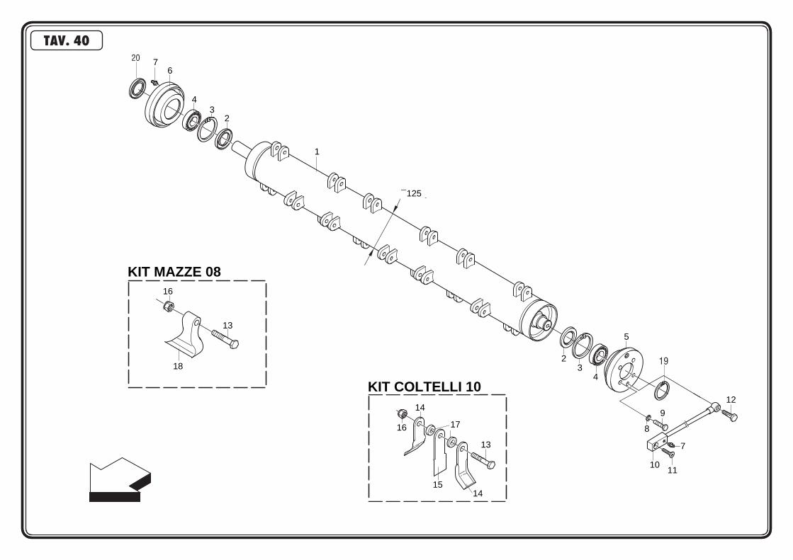
¯ 125
1
76
43
2
2
43
5
8
9
11
7
10
12
KIT MAZZE 08
KIT COLTELLI 10
16
14
15
13
14
16
18
13
17
TAV. 40
19
20

POS CODICE DESCRIZIONE DESCRIPTION DESCRIPTION BENENNUNG DESCRIPCION
1 M22410401 TUBO ROTORE VITA 100 COMPLETE ROTOR VITA 100 ROTOR COMPL. VITA 100 LAEUFER KOMPL. VITA 100 ROTOR COMPL. VITA 100 M22412401 TUBO ROTORE VITA 120 COMPLETE ROTOR VITA 120 ROTOR COMPL. VITA 120 LAEUFER KOMPL. VITA 120 ROTOR COMPL. VITA 120 M22414401 TUBO ROTORE VITA 140 COMPLETE ROTOR VITA 140 ROTOR COMPL. VITA 140 LAEUFER KOMPL. VITA 140 ROTOR COMPL. VITA 140 M22416401 TUBO ROTORE VITA 160 COMPLETE ROTOR VITA 160 ROTOR COMPL. VITA 160 LAEUFER KOMPL. VITA 160 ROTOR COMPL. VITA 160 M22417401 TUBO ROTORE VITA 170 COMPLETE ROTOR VITA 170 ROTOR COMPL. VITA 170 LAEUFER KOMPL. VITA 170 ROTOR COMPL. VITA 170 M22419401 TUBO ROTORE VITA 190 COMPLETE ROTOR VITA 190 ROTOR COMPL. VITA 190 LAEUFER KOMPL. VITA 190 ROTOR COMPL. VITA 1902 F03010136 ANELLO T.A. 45X 72X 8 D3760NBR OIL SEAL 45X72X8 PARE-HUILE 45X72X8 OELABDICHTUNG 45X72X8 JUNTA DE ACEITE 45X72X83 F02050403 ANELLO SEEGER D.72UNI3654 SEEGER RING D.72 BAGUE SEEGER D.72 SEEGERRING D.72 ANILLO SEEGER D.724 F04010090 CUSC.D35 D72 B23 2207 ETN9 BEARING 2207 D35 D72 B23 ROULEMENT 2207 D35 D72 B23 LAGER 2207 D35 D72 B23 COJINETE 2207 D35 D72 B235 M22400406 SUPPORTO CUSC.ROTORE L.E. BEARING SUPPORT SUPPORT ROULEMENT LAGERHALTER SOPORTE COJINETE6 M22400405 SUPPORTO CUSC. ROTORE L.T. BEARING SUPPORT SUPPORT ROULEMENT LAGERHALTER SOPORTE COJINETE7 F01100011 ING.M 6X1 7663-A 9SMNPB28 ZG SPHERE NIPPLE M6X1/A GRAISSEUR A BILLES M6X1/A KUGELFETTBsCHSE M6X1/A ENGRAS. DE ESFERAS M6X1/A8 F01480123 ROSET.GROWER M12 ZGP EXTRA P. GROWER WASHER D.12 RONDELLE GROWER D.12 SCHEIBE GROWER D.12 ARANDELA GROWER D.129 F01010283 VITE TE M12X30 BOLT M 12X30 VIS M 12X30 SCHRAUBE M 12X30 TORNILLO M 12X3010 T24004000 ASSIEME INGRASSATORE GREASE NIPPLE GRAISSEUR SCHMIERNIPPEL ENGRASADOR11 F01030058 VITE TSPEI M8X1,25X30 5933 ZG BOLT M 8 VIS M 8 SCHRAUBE M 8 TORNILLO M 812 T24004003 VITE FORATA PER INGRASSAGGIO BOLT VIS SCHRAUBE TORNILLO13 F01010125 VITE M16X1,5X100 5738 10.9 ZD BOLT M 16X1,5X100 VIS M16X1,5X100 SCHRAUBE M 16X1,5X100 TORNILLO M 16X1,5X10014 T21004040 COLTELLO A Y L=130 BLADE “Y” L=130 COUTEAU Y06 BC/E/L-CR L=130 MESSER “Y” L=130 CUCHILLO “Y” L=13015 T21004050 COLTELLO DIRITTO INT.L=130 STRAIGHT BLADE L=130 COTEAU L=130 MESSER L=130 CUCHILLO L=13016 F01230084 DADO AUT.A M16X1,5 7473 6S ZG SELF LOCKING NUT M16X1,5 ECROU AUTOBL. M16X1,5 SELBSTSPERR.MUTTER M16X1,5 DADO AUTOBL. M16X1,517 T21004045 DISTANZIALE COLTELLI ZPG BLADE SPACER ENTRTOISE COTEAU MESSER DISTANZSTUECK DISTANCIADOR CUCHILLO18 T24004025 MAZZA 08 STAMPATA 130 HAMMER L=130 MARTEAUX L=130 SCHLEGEL L=130 MARTILLO L=13019 F02050146 ANELLO E. DE 35X 1,5 U7435 C70 ELASTIC RING DE 35X 1,5 U7435 BAGUE ELASTIQUE DE 35X 1,5 RING DE 35X 1,5 U7435 C70 ANILLO DE 35X 1,5 U7435 C7020 F03010085 ANELLO T.A. 35X 62X 7 D3760NBR OIL SEAL 35X62X7 PARE-HUILE 35X62X7 OELABDICHTUNG 35X62X7 JUNTA DE ACEITE 35X62X7
TAV. 40
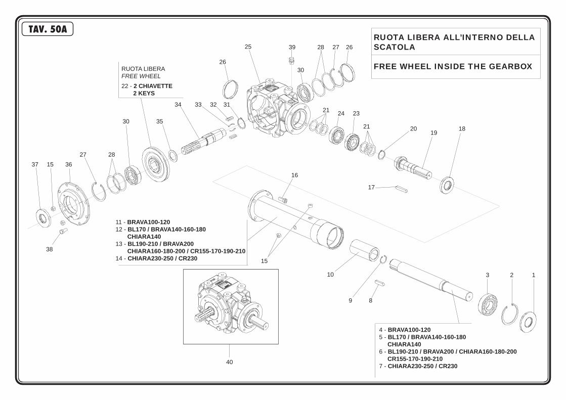
TAV. 50A
3 2 1
4 - BRAVA100-1205 - BL170 / BRAVA140-160-180 CHIARA1406 - BL190-210 / BRAVA200 / CHIARA160-180-200 CR155-170-190-210 7 - CHIARA230-250 / CR230
9 8
11 - BRAVA100-12012 - BL170 / BRAVA140-160-180 CHIARA14013 - BL190-210 / BRAVA200 CHIARA160-180-200 / CR155-170-190-210 14 - CHIARA230-250 / CR230 15
16
20 18
17
21
24 23 21
RUOTA LIBERAFREE WHEEL22 - 2 CHIAVETTE 2 KEYS
39 28 27 26
3026
34 33 32 31
30 35
19
27 28 37 15 36
38
40
25
10
RUOTA LIBERA ALL’INTERNO DELLA SCATOLA
FREE WHEEL INSIDE THE GEARBOX

POS CODICE DESCRIZIONE DESCRIPTION DESCRIPTION BENENNUNG DESCRIPCION TAV. 50A1 F03010280 ANEL. T.AS 40X 90X 7 D3760NBR RING T.AS 40X 90X 7 D3760 NBR BAGUE T.AS 40X 90X 7 D3760 NBR SCHUTZRING 40X90X7 D3760 NBR ANILLO T.A 40X 90X 7 D3760 NBR2 F02050447 ANELLO E. DI 90X 3 U7437 C70 SEEGER RING D.90 BAGUE SEEGER D.90 SEEGERRING D.90 ANILLO SEEGER D.903 F04010218 CUSC.D40 D90 B23 6308 BEARING 6308 ROULEMENT 6308 LAGER 6308 COJINETE 63084 T24121218 ALBERO RINVIO D=45 L=157 SHAFT D=45 L=157 ARBRE D=45 L=157 ZENTRALWELLE D=45 L=157 ARBOL D=45 L=1575 T24151218 ALBERO RINVIO D=45 L=272 SHAFT D=45 L=272 ARBRE D=45 L=272 ZENTRALWELLE D=45 L=272 ARBOL D=45 L=2726 T24191218 ALBERO RINVIO D=45 L=437 SHAFT D=45 L=437 ARBRE D=45 L=437 ZENTRALWELLE D=45 L=437 ARBOL D=45 L=4377 T24231218 ALBERO RINVIO D=45 L=607 SHAFT D=45 L=607 ARBRE D=45 L=607 ZENTRALWELLE D=45 L=607 ARBOL D=45 L=6078 F02150132 LINGUETTA 12X 8X 50 U6604A KEY 12X8X50 CLAVETTE 12X8X50 KEIL 12X8X50 LLAVE 12X8X509 F02050315 ANELLO E. DI 34X 1,5 U7437 C70 SEEGER RING 34X1,5 U7437 C70 SEEGER E. 34X 1,5 U7437 C70 SEEGERING E. 34X 1,5 U7437 C70 ANILLO E. 34 X1,5 U7437 C7010 T40000029 GIUNTO SCATOLA MOLTIP.ALBERO COUPLING JOINT KUPPLUNG JUNTA11 T24121209 DISTANZIALE TRASMISSIONE L=309 TRANSMISSION SPACER L=309 ENTRETOISE TRANSMISSION L=309 ANTRIEBSDISTANZSTUECK L=309 DISTANCIADOR TRASMISION L=30912 T24151209 DISTANZIALE TRASMISSIONE L=421 TRANSMISSION SPACER L=421 ENTRETOISE TRANSMISSION L=421 ANTRIEBSDISTANZSTUECK L=421 DISTANCIADOR TRASMISION L=42113 T241191209 DISTANZIALE TRASMISSIONE L=589 TRANSMISSION SPACER L=589 ENTRETOISE TRANSMISSION L=589 ANTRIEBSDISTANZSTUECK L=589 DISTANCIADOR TRASMISION L=58914 T24231209 DISTANZIALE TRASMISSIONE L=759 TRANSMISSION SPACER L=759 ENTRETOISE TRANSMISSION L=759 ANTRIEBSDISTANZSTUECK L=759 DISTANCIADOR TRASMISION L=75915 M29100112 TAPPO SCARICO OLIO OIL OUTLET PLUG BOUCHON DE VIDANGE HUILE OELABLASSPFROPFEN TAPON DESCARGADO ACEITE16 F01040121 VITE M10X 1,5X35 U5931 8.8 ZN BOLT M10X1,5X35 VIS M10X1,5X35 SCHRAUBE M10X1,5X35 TORNILLO M10X1,5X3517 F02150106 LINGUETTA 10X 8X 65 U6604A KEY 10X8X65 FEDER 10X8X65 CLAVETTE 10X8X65 LLAVE 10X8X6518 F03010088 ANELLO T.AS.35X 72X10 D3760NBR OIL SEAL 35X72X10 PARA-HUILLE 35X72X10 OELABDICHTUNG 35X72X10 PARA-ACEITE 35X72X1019 M07400003 PIGN.Z12 M4.35 BEVEL PINION PIGNON CONIQUE KEGELRITZEL PINON CONICO20 M07400004 SEEGER 35X33X2.5 SEEGER RING 35X33X2.5 BAGUE SEEGER D 35X33X2,5 SEEGERRING D 35X33X2.5 ANILLO D 35X33X2,521 M07400002 KIT SPES.0,3/4/5 REINFORCEMENTS RENFORTS VERSTAERKERUNGEN RENFUERZOS22 M07400007 CORONA*Z36 M4.35 RING BEVEL GEAR COURONNE CONIQUE KEGELRADKRANZ CORONA CONICA23 F04050014 CUSCINETTO 30207 BEARING 30207 ROULEMENT 30207 LAGER 30207 COJINETE 3020724 F04050070 CUSC.D35 D72 T24,25 32207 BEARING 32207 ROULEMENT 32207 LAGER 32207 COJINETE 3220725 T24001202 CORPO RIDUTTORE GEARBOX BOITE DE VITESSE WECHSELGETRIEBEGEHAEUSE CAJA CAMBIO26 F03011026 PARAOLIO TAPPO CIECO 80X10 CAP 80X10 BOUCHON 80X10 DECKEL 80X10 CORCHO 80X1027 F02050425 ANELLO E. DI 80X 2,5 U7437 C70 SEEGER RING D.80 BAGUE SEEGER D.80 SEEGERRING D.80 ANILLO SEEGER D.8028 M07400006 KIT SPESSORI 0,3/4/5 REINFORCEMENTS RENFORTS VERSTAERKERUNGEN RENFUERZOS30 F04010216 CUSC.D35 D80 B21 6307 BEARING 6307 ROULEMENT 6307 LAGER 6307 COJINETE 620731 M03400007 SEEG.42X39,5X1,75 ELASTIC RING 42X39,5X1,75 BAGUE ELASTIQUE 42X39,5X1,75 RING 42X39,5X1,75 ANILLO UNI 42X39,5X1,7532 M07400005 LINGUETTA PARALLEL KEY CLAVETTE FEDER LLAVE33 M03400009 MOLLA X CHIAVET. SPRING RESSORT FEDER MUELLE34 M07400001 1”3/8 Z6 ALBERO* SHAFT ARBRE ZENTRALWELLE ARBOL35 M03400008 SPESS. 48X35,3X1 THICKNESS 48X35,3X1 EPAISSEUR 48X35,3X1 DISTANZSTUECK 48X35,3X1 ESPESOR 48X35,3X136 T24001208 FLANGIA CORPO TRASMISSIONE GEARBOX COVER COUVERCLE BOITE A VITESSES GETRIEBEDECKEL TAPA CAJA CAMBIO37 F03010265 ANELLO T.AS 35X 80X10 D3760NBR RING T.AS 35X80X10 D3760 NBR BAGUE T.AS 35X 80X10 D3760 NBR SCHUTZRING 35X80X10 D3760 NBR INEL T.AS 35X80X10 D3760 NBR38 F01020474 VITE M10X1,5 X 25 5739 8.8 BR BOLT M 10X25 VIS M 10X25 SCHRAUBE M 10X25 TORNILLO M 10X2539 F03150718 TAPPO 3/8” GAS CON SFIATO OIL BREATHER PLUG BOUCHON D’HUILE SOUPIRAIL OELENTLUEFTERSTOPFEN TAPON ACEITE40 M07400201 MOLTIPLICATORE COMER GIRAFFA GEARBOX BOITE DE VITESSE WECHSELGETRIEBEGEHAEUSE CAJA CAMBIO
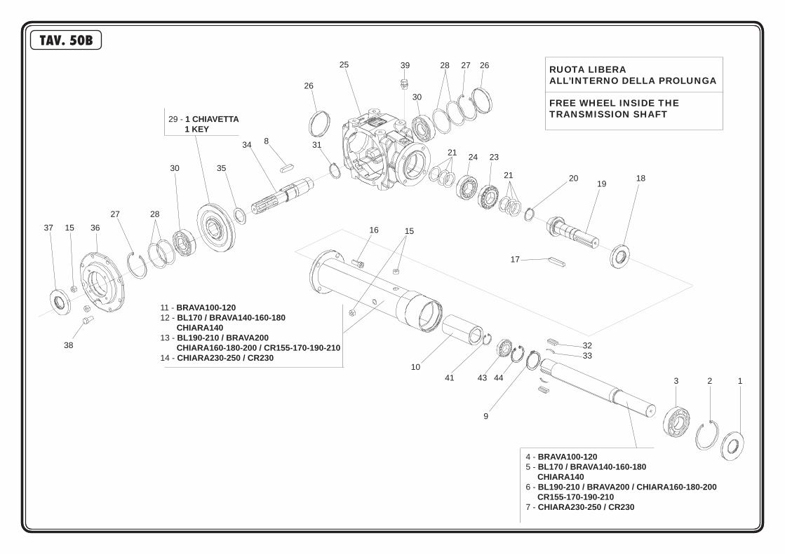
3 2 1
4 - BRAVA100-1205 - BL170 / BRAVA140-160-180 CHIARA1406 - BL190-210 / BRAVA200 / CHIARA160-180-200 CR155-170-190-210 7 - CHIARA230-250 / CR230
9
11 - BRAVA100-12012 - BL170 / BRAVA140-160-180 CHIARA14013 - BL190-210 / BRAVA200 CHIARA160-180-200 / CR155-170-190-210 14 - CHIARA230-250 / CR230
1516
20 18
17
21
24 23 21
29 - 1 CHIAVETTA 1 KEY
39 28 27 26
3026
34 31
30 35
19
27 28 37 15 36
38
25
10
8
3233
41 43 44
RUOTA LIBERA ALL’INTERNO DELLA PROLUNGA
FREE WHEEL INSIDE THE TRANSMISSION SHAFT
TAV. 50B

POS CODICE DESCRIZIONE DESCRIPTION DESCRIPTION BENENNUNG DESCRIPCION
1 F03010280 ANEL. T.AS 40X 90X 7 D3760NBR RING T.AS 40X 90X 7 D3760 NBR BAGUE T.AS 40X 90X 7 D3760 NBR SCHUTZRING 40X90X7 D3760 NBR ANILLO T.A 40X 90X 7 D3760 NBR2 F02050447 ANELLO E. DI 90X 3 U7437 C70 SEEGER RING D.90 BAGUE SEEGER D.90 SEEGERRING D.90 ANILLO SEEGER D.903 F04010218 CUSC.D40 D90 B23 6308 BEARING 6308 ROULEMENT 6308 LAGER 6308 COJINETE 63084 T24121206 ALBERO RINVIO D=45 L=157 SHAFT D=45 L=157 ARBRE D=45 L=157 ZENTRALWELLE D=45 L=157 ARBOL D=45 L=1575 T24151206 ALBERO RINVIO D=45 L=272 SHAFT D=45 L=272 ARBRE D=45 L=272 ZENTRALWELLE D=45 L=272 ARBOL D=45 L=2726 T24191206 ALBERO RINVIO D=45 L=437 SHAFT D=45 L=437 ARBRE D=45 L=437 ZENTRALWELLE D=45 L=437 ARBOL D=45 L=4377 T24231206 ALBERO RINVIO D=45 L=607 SHAFT D=45 L=607 ARBRE D=45 L=607 ZENTRALWELLE D=45 L=607 ARBOL D=45 L=6078 F02150133 LINGUETTA 12X 8X 55 U6604A KEY 12X8X55 CLAVETTE 12X8X55 KEIL 12X8X55 LLAVE 12X8X559 F02050315 ANELLO E. DI 34X 1,5 U7437 C70 SEEGER RING 34X1,5 U7437 C70 SEEGER E. 34X 1,5 U7437 C70 SEEGERING E. 34X 1,5 U7437 C70 ANILLO E. 34 X1,5 U7437 C7010 T40000017 GIUNTO SCATOLA MOLTIP.ALBERO COUPLING JOINT KUPPLUNG JUNTA11 T24121209 DISTANZIALE TRASMISSIONE L=309 TRANSMISSION SPACER L=309 ENTRETOISE TRANSMISSION L=309 ANTRIEBSDISTANZSTUECK L=309 DISTANCIADOR TRASMISION L=30912 T24151209 DISTANZIALE TRASMISSIONE L=421 TRANSMISSION SPACER L=421 ENTRETOISE TRANSMISSION L=421 ANTRIEBSDISTANZSTUECK L=421 DISTANCIADOR TRASMISION L=42113 T241191209 DISTANZIALE TRASMISSIONE L=589 TRANSMISSION SPACER L=589 ENTRETOISE TRANSMISSION L=589 ANTRIEBSDISTANZSTUECK L=589 DISTANCIADOR TRASMISION L=58914 T24231209 DISTANZIALE TRASMISSIONE L=759 TRANSMISSION SPACER L=759 ENTRETOISE TRANSMISSION L=759 ANTRIEBSDISTANZSTUECK L=759 DISTANCIADOR TRASMISION L=75915 M29100112 TAPPO SCARICO OLIO OIL OUTLET PLUG BOUCHON DE VIDANGE HUILE OELABLASSPFROPFEN TAPON DESCARGADO ACEITE16 F01040121 VITE M10X 1,5X35 U5931 8.8 ZN BOLT M10X1,5X35 VIS M10X1,5X35 SCHRAUBE M10X1,5X35 TORNILLO M10X1,5X3517 F02150106 LINGUETTA 10X 8X 65 U6604A KEY 10X8X65 FEDER 10X8X65 CLAVETTE 10X8X65 LLAVE 10X8X6518 F03010088 ANELLO T.AS.35X 72X10 D3760NBR OIL SEAL 35X72X10 PARA-HUILLE 35X72X10 OELABDICHTUNG 35X72X10 PARA-ACEITE 35X72X1019 M07400003 PIGN.Z12 M4.35 BEVEL PINION PIGNON CONIQUE KEGELRITZEL PINON CONICO20 M07400004 SEEGER 35X33X2.5 SEEGER RING 35X33X2.5 BAGUE SEEGER D 35X33X2,5 SEEGERRING D 35X33X2.5 ANILLO D 35X33X2,521 M07400002 KIT SPES.0,3/4/5 REINFORCEMENTS RENFORTS VERSTAERKERUNGEN RENFUERZOS23 F04010175 CUSCINETTO 30207 BEARING 30207 ROULEMENT 30207 LAGER 30207 COJINETE 3020724 F04050070 CUSC.D35 D72 T24,25 32207 BEARING 32207 ROULEMENT 32207 LAGER 32207 COJINETE 3220725 T24001202 CORPO RIDUTTORE GEARBOX BOITE DE VITESSE WECHSELGETRIEBEGEHAEUSE CAJA CAMBIO26 F03011026 PARAOLIO TAPPO CIECO 80X10 CAP 80X10 BOUCHON 80X10 DECKEL 80X10 CORCHO 80X1027 F02050425 ANELLO E. DI 80X 2,5 U7437 C70 SEEGER RING D.80 BAGUE SEEGER D.80 SEEGERRING D.80 ANILLO SEEGER D.8028 M07400006 KIT SPESSORI 0,3/4/5 REINFORCEMENTS RENFORTS VERSTAERKERUNGEN RENFUERZOS29 M07400018 CORONA*Z36 D.40 RING BEVEL GEAR COURONNE CONIQUE KEGELRADKRANZ CORONA CONICA30 F04010180 CUSC.D40 D80 B21 6307 BEARING 6307 ROULEMENT 6307 LAGER 6307 COJINETE 620731 M03400007 SEEG.42X39,5X1,75 ELASTIC RING 42X39,5X1,75 BAGUE ELASTIQUE 42X39,5X1,75 RING 42X39,5X1,75 ANILLO UNI 42X39,5X1,7532 M07400005 LINGUETTA PARALLEL KEY CLAVETTE FEDER LLAVE33 M03400009 MOLLA X CHIAVET. SPRING RESSORT FEDER MUELLE34 T24001207 1”3/8 Z6 ALBERO* SHAFT ARBRE ZENTRALWELLE ARBOL35 M03400008 SPESS. 48X35,3X1 THICKNESS 48X35,3X1 EPAISSEUR 48X35,3X1 DISTANZSTUECK 48X35,3X1 ESPESOR 48X35,3X136 T24001208 FLANGIA CORPO TRASMISSIONE GEARBOX COVER COUVERCLE BOITE A VITESSES GETRIEBEDECKEL TAPA CAJA CAMBIO37 F03010277 ANEL. T.AS 40X 80X10 D3760NBR RING T.AS 40X80X10 D3760 NBR BAGUE T.AS 40X 80X10 D3760 NBR SCHUTZRING 40X80X10 D3760 NBR INEL T.AS 40X80X10 D3760 NBR38 F01020474 VITE M10X1,5 X 25 5739 8.8 BR BOLT M 10X25 VIS M 10X25 SCHRAUBE M 10X25 TORNILLO M 10X2539 F03150718 TAPPO 3/8” GAS CON SFIATO OIL BREATHER PLUG BOUCHON D’HUILE SOUPIRAIL OELENTLUEFTERSTOPFEN TAPON ACEITE41 F02050315 ANELLO E. DI 34X 1,5 U7437 C70 SEEGER RING 34X1,5 U7437 C70 SEEGER E. 34X 1,5 U7437 C70 SEEGERING E. 34X 1,5 U7437 C70 ANILLO E. 34 X1,5 U7437 C7043 F04010131 CUSC.D20 D42 B12 6004-2RSH EX> BEARING 6004 2RS EX. SKF ROULEMENT 6004 LAGER 6004 COJINETE 600444 F02050359 ANELLO E. DI 42X1,75 U7437 C70 ELASTIC RING 42X1,75 BAGUE ELASTIQUE 42X1,75 RING 42X1,75 ANILLO 42X1,75
TAV. 50B
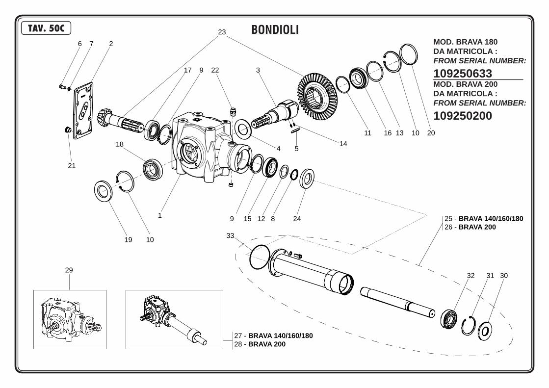
1 9 15 12 8 24
4 5
11 16 13 10 20
17 9 22 3
23
6 7 2
21
18
19 10
14
25 - BRAVA 140/160/18026 - BRAVA 200
29
27 - BRAVA 140/160/18028 - BRAVA 200
32 31 30
33
BONDIOLITAV. 50CMOD. BRAVA 180DA MATRICOLA :FROM SERIAL NUMBER:
109250633MOD. BRAVA 200DA MATRICOLA :FROM SERIAL NUMBER:
109250200

POS CODICE DESCRIZIONE DESCRIPTION DESCRIPTION BENENNUNG DESCRIPCION TAV. 50C1 M30500151 SCATOLA 2061 +ATT.P0 GEARBOX BOITE DE VITESSE WECHSELGETRIEBEGEHAEUSE CAJA CAMBIO2 M30500108 KIT COPXSCAT 2061 GEARBOX COVER COUVERCLE BOITE A VITESSES GETRIEBEDECKEL TAPA CAJA CAMBIO3 M30500152 ALBERO AS X2061 RL SHAFT ARBRE ZENTRALWELLE ARBOL4 M30500103 DIST.DI SPALLAMENTO SPACER ENTRETOISE DISTANZSTUECK DISTANCIADOR5 M30500104 PIASTRI.RL L=40X2061 PLATE PLAQUETTE PLATTE PLAQUITA6 F01020436 VITE M 8X1,25X 20 U5739 8.8 ZN SCREW M8X1,25X20 U5739 8.8 ZN VIS M8X1,25X20 U5739 8.8 ZN SCHRA. M8X1,25X20 U5739 8.8 ZN TORN. M8X1,25X20 U5739 8.8 ZN7 F01480099 ROS.G 8,4X14,4X2,7 EX.C70 ZN GROWER WASHER D.8 RONDELLE GROWER D.8 SCHEIBE GROWER D.8 ARANDELA GROWER D.88 M30500154 ANILLO E.ES.35X2,5 SEEGER RING E.35X2,5 SEEGER E. 35X2,5 SEEGERING E. 35X2,5 ANILLO E. 35X2,59 F02050403 ANELLO E. DI 72X 2,5 U7437 C70 SEEGER RING E.72X2,5 U7437 C70 SEEGER E. 72X 2,5 U7437 C70 SEEGERING E. 72X 2,5 U7437 C70 ANILLO E. 72X 2,5 U7437 C7010 F02050425 ANELLO E. DI 80X 2,5 U7437 C70 SEEGER RING D.80 BAGUE SEEGER D.80 SEEGERRING D.80 ANILLO SEEGER D.8011 M30500109 ANELLO E. D.50 M3200 ELASTIC RING D.50 BAGUE ELASTIQUE D.50 RING D.50 ANILLO D.5012 M30500105 ANELLI SPESS. E.035 REINFORCEMENTS RENFORTS VERSTAERKERUNGEN RENFUERZOS13 M30500106 ANELLI SPESS. I.080 REINFORCEMENTS RENFORTS VERSTAERKERUNGEN RENFUERZOS14 M50400905 MOLLA PER RUOTA LIBERA SPRING RESSORT FEDER RESORTE15 F04010175 CUSC.D35 D72 B17 6207 BEARING 6207 ROULEMENT 6207 LAGER 6207 COJINETE 620716 F04010180 CUSC.D40 D80 B18 6208 BEARING 6208 ROULEMENT 6208 LAGER 6208 COJINETE 620817 F04050014 CUSC.D35 D72 T18,25 30207 BEARING 30207 ROULEMENT 30207 LAGER 30207 COJINETE 3020718 F04050017 CUSC.D40 D80 T19,75 30208 BEARING 30208 ROULEMENT 30208 LAGER 30208 COJINETE 3020819 F03010277 ANELLO T.AS 40X 80X10 D3760NBR OIL SEAL 40X80X10 BOURAGE 40X80X10 OELABDICHTUNG 40X80X10 JUNTA DE ACEITE 40X80X1020 F03011026 TAPPO CHIUSURA D=80 X 10 GA CAP 80X10 BOUCHON 80X10 DECKEL 80X10 CORCHO 80X1021 F03150719 TAPPO 3/8 GAS CAP BOUCHON DECKEL CORCHO22 F03150606 TAPPO SFIATO 1/4 GAS POT58 OIL BREATHING PLUG 1/4 GAS BOUCHON REFOUL. ª GAZ POT58 ENTLsFTUNGSPFROPFEN 1/4 GAS PO TAPN PURGADOR 1/4 GAS POT58 D23 M30500153 COPPIA CON.2061 RLNR BEVEL GEAR PAIR COUPLE CONIQUE KEGELRITZELSATZ PAR CONICO24 F03010265 ANELLO T.AS 35X 80X10 D3760NBR RING T.AS 35X80X10 D3760 NBR BAGUE T.AS 35X 80X10 D3760 NBR SCHUTZRING 35X80X10 D3760 NBR INEL T.AS 35X80X10 D3760 NBR25 M28419102 PROLUNGA TRASMISSIONE L=620 TRANS. SHAFT EXTENSION RALLONGE ARBRE DE TRANSMISS. VERLZNGERUNG ANTRIEBSWELLE EXTENSION ARBOL TRANS.26 M28423102 PROLUNGA TRASMISSIONE L=800 TRANS. SHAFT EXTENSION RALLONGE ARBRE DE TRANSMISS. VERLZNGERUNG ANTRIEBSWELLE EXTENSION ARBOL TRANS.27 27 M28419202 CORPO MOLT.540 RPM L=780 GEARBOX COMPL. L=780 BOITE DE VITESSE COMPL. L=780 KOMPL. WECHSELGETRIEBE L=780 CAJA CAMBIO COMPLETA L=78028 M28423202 CORPO MOLTIP.540 RPM L=960 GEARBOX COMPL. L=960 BOITE DE VITESSE COMPL. L=960 KOMPL. WECHSELGETRIEBE L=960 CAJA CAMBIO COMPLETA L=96029 M28400101 SCATOLA MOLTIPL.540 BONDIOLI GEARBOX BOITE DE VITESSE WECHSELGETRIEBEGEHAEUSE CAJA CAMBIO30 M30500160 ANELLO T. 40X90X10 OIL SEAL 40X90X10 PARE-HUILE 40X90X10 OELABDICHTUNG 40X90X10 PARA-ACEITE 40X90X1031 F02050447 ANELLO E. DI 90X 3 U7437 C70 SEEGER RING D.90 BAGUE SEEGER D.90 SEEGERRING D.90 ANILLO SEEGER D.9032 F04010218 CUSC.D40 D90 B23 6308 BEARING 6308 ROULEMENT 6308 LAGER 6308 COJINETE 630833 M30500161 ANEL.OR.72.69X2.62 RING OR 72.69X2.62 BAGUE OR 72.69X2.62 RING OR 72.69X2.62 ANILLO OR 72.69X2.62
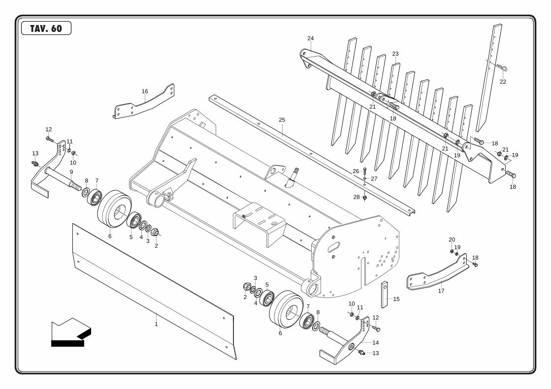
16
13
12
11
10
9
8 7
6 5 43
2
1
2
3
4
5
6
78
1011
12
14
13
1517
2019
18
24
21
18
23
2119
22
1821
19
18
2525
2627
28
TAV. 60

POS CODICE DESCRIZIONE DESCRIPTION DESCRIPTION BENENNUNG DESCRIPCION
1 M28410504 LAMIERA ANTIUSURA BRAVA 100 SHEET METAL-BRAVA 100 TOLE-BRAVA 100 BLECH-BRAVA 100 CHAPA-BRAVA 100 M28412504 LAMIERA ANTIUSURA BRAVA 120 SHEET METAL-BRAVA 120 TOLE-BRAVA 120 BLECH-BRAVA 120 CHAPA-BRAVA 120 M28414504 LAMIERA ANTIUSURA BRAVA 140 SHEET METAL-BRAVA 140 TOLE-BRAVA 140 BLECH-BRAVA 140 CHAPA-BRAVA 140 M28416504 LAMIERA ANTIUSURA BRAVA 160 SHEET METAL-BRAVA 160 TOLE-BRAVA 160 BLECH-BRAVA 160 CHAPA-BRAVA 160 M28418504 LAMIERA ANTIUSURA BRAVA 180 SHEET METAL-BRAVA 180 TOLE-BRAVA 180 BLECH-BRAVA 180 CHAPA-BRAVA 180 M28420504 LAMIERA ANTIUSURA BRAVA 200 SHEET METAL-BRAVA 200 TOLE-BRAVA 200 BLECH-BRAVA 200 CHAPA-BRAVA 2002 F01230084 DADO AUT.A M16X1,5 7473 6S ZG SELF LOCKING NUT M16X1,5 ECROU AUTOBL. M16X1,5 SELBSTSPERR.MUTTER M16X1,5 DADO AUTOBL. M16X1,53 F01410100 ROSET.PER T.E.17X30 UNI6592 PLANE WASHER D.16 RONDELLE D.16 SCHEIBE D.16 ARANDELA D.164 F01410124 ROSETTA 20X34 UNI 6593-69 ZPG PLANE WASHER D. 20 RONDELLE D. 20 SCHEIBE D.20 ARANDELLA D.205 F04010131 CUSCINETTO 6004 2RS BEARING 6004 ROULEMENT 6004 LAGER 6004 COJINETE 60046 F06120100 RUOTA D=190 SP=95 WHEEL ROUE RAD RUEDA7 F04010131 CUSCINETTO 6004 2RS BEARING 6004 ROULEMENT 6004 LAGER 6004 COJINETE 60048 F01410124 ROSETTA 20X34 UNI 6593-69 ZPG PLANE WASHER D. 20 RONDELLE D. 20 SCHEIBE D.20 ARANDELLA D.209 T19008005 ASS.SUPPORTO RU0TA SX WHEEL LINKAGE ATTELAGE ROUE RAD HALTER ATAQUE RUEDA10 F01230058 DADO AUT.A M12X1,25 7473 6S ZG SELF LOCKING NUT M12X1,25 ECROU AUTOBL. M12X1,25 SELBSTSPERR.MUTTER M12X1,25 DADO AUTOBL. M12X1,2511 F01410076 ROS.M12 13X 24X2,5 U6592 ZG PLANE WASHER D.12 RONDELLE D.12 SCHEIBE D.12 ARANDELA D.1212 F01010291 VITE M12X1,25X 40 5740 8.8 ZG BOLT M 12X40 VIS M 12X40 SCHRAUBE M 12X40 TORNILLO M 12X4013 F01100011 ING.M 6X1 7663-A 9SMNPB28 ZG SPHERE NIPPLE M6X1/A GRAISSEUR A BILLES M6X1/A KUGELFETTBsCHSE M6X1/A ENGRAS. DE ESFERAS M6X1/A14 T19008010 ASS.SUPPORTO RU0TA DX WHEEL LINKAGE ATTELAGE ROUE RAD HALTER ATAQUE RUEDA15 T16005012 CHIUSURA LATERALE V REAR LATERAL PANEL CAPOT ARRIERE LATERAL HINTERE BLECH PLANCHA LATERALE16 T23005213 SLITTA DX BC-BE-CL RIGHT SKID GLISSIERE COTE DROIT RECHTS GLEITKUFE TRINEO LADO DERECHO17 T23005214 SLITTA SX BC-BE-CL LEFT SKID GLISSIERE COTE GAUCHE LINKS GLEITKUFE TRINEO LADO IZQUIERDO18 F01010288 VITE M12X1,25X 35 5740 8.8 BR BOLT M 12X1,25X35 VIS M 12X1,25X35 SCHRAUBE M 12X1,25X35 TORNILLO M 12X1,25X3519 F01410076 ROS.M12 13X 24X2,5 U6592 ZG PLANE WASHER D.12 RONDELLE D.12 SCHEIBE D.12 ARANDELA D.1220 F01230058 DADO AUT.A M12X1,25 7473 6S ZG SELF LOCKING NUT M12X1,25 ECROU AUTOBL. M12X1,25 SELBSTSPERR.MUTTER M12X1,25 DADO AUTOBL. M12X1,2521 F01220047 DADO METAL M12X1,25 D980 6S ZG SELF LOCKING NUT M12X1,25 980V ECROU AUTOBL. M12X1,25 980-V SELBSTSP.MUTT. M12X1,25 980-V DADO AUTOBL. M12X1,25 980-V22 F02200374 COPIGLIA R 4X82 ZN B/108 SPLIT PIN 5X100 GOUPILLE 5X100 SPLINT 5X100 PASADOR 5X10023 T21005015 ROSTRO COLLECTING RAKE RETEAU SCHNABEL ROSTRO24 M28410574 COF.DENTI RACC.BRAVA 100 BRACKET BRAVA 100 SUPPORT BRAVA 100 HALTERUNG BRAVA 100 SOPORTE BRAVA 100 M28412574 COF.DENTI RACC.BRAVA 120 BRACKET BRAVA 120 SUPPORT BRAVA 120 HALTERUNG BRAVA 120 SOPORTE BRAVA 120 M28414574 COF.DENTI RACC.BRAVA 140 BRACKET BRAVA 140 SUPPORT BRAVA 140 HALTERUNG BRAVA 140 SOPORTE BRAVA 140 M28416574 COF.DENTI RACC.BRAVA 160 BRACKET BRAVA 160 SUPPORT BRAVA 160 HALTERUNG BRAVA 160 SOPORTE BRAVA 160 M28418574 COF.DENTI RACC.BRAVA 180 BRACKET BRAVA 180 SUPPORT BRAVA 180 HALTERUNG BRAVA 180 SOPORTE BRAVA 180 M28420574 COF.DENTI RACC.BRAVA 200 BRACKET BRAVA 200 SUPPORT BRAVA 200 HALTERUNG BRAVA 200 SOPORTE BRAVA 20025 T23105021 CONTROCOLTELLO BC100 COUNTER BLADE BC100 CONTRE COUTEAU BC100 GEGENMESSER BC100 CONTRO CUCHILLAS BC100 T23125021 CONTROCOLTELLO BC120 COUNTER BLADE BC120 CONTRE COUTEAU BC120 GEGENMESSER BC120 CONTRO CUCHILLAS BC120 T23145021 CONTROCOLTELLO BC140 COUNTER BLADE BC140 CONTRE COUTEAU BC140 GEGENMESSER BC140 CONTRO CUCHILLAS BC140 T23165021 CONTROCOLTELLO BC160 COUNTER BLADE BC160 CONTRE COUTEAU BC160 GEGENMESSER BC160 CONTRO CUCHILLAS BC160 T23185021 CONTROCOLTELLO BCA 180 COUNTER BLADE BCA 180 CONTRE COUTEAU BCA 180 GEGENMESSER BCA 180 CONTRO CUCHILLAS BCA 180 T23205021 CONTROCOLTELLO BCA 200 COUNTER BLADE BCA 200 CONTRE COUTEAU BCA 200 GEGENMESSER BCA 200 CONTRO CUCHILLAS BCA 20026 F01010241 VITE M10X1,25X 20 5740 8.8 BR BOLT M 10X1,25X20 VIS M 10X1,25X20 SCHRAUBE M 10X1,25X20 TORNILLO M 10X1,25X2027 F01410064 ROSET.PER T.E.10,5X21 ZPG 6592 WASHER 10,5X21 RONDELLE 10,5X21 SCHEIBE 10,5X21 ARANDELA 10,5X2128 F01230046 DADO AUT.A M10X1,25 7473 6S ZG SELF LOCKING NUT M10X1,25 ECROU AUTOBL. M10X1,25 SELBSTSPERR.MUTTER M10X1,25 DADO AUTOBL. M10X1,25
TAV. 60
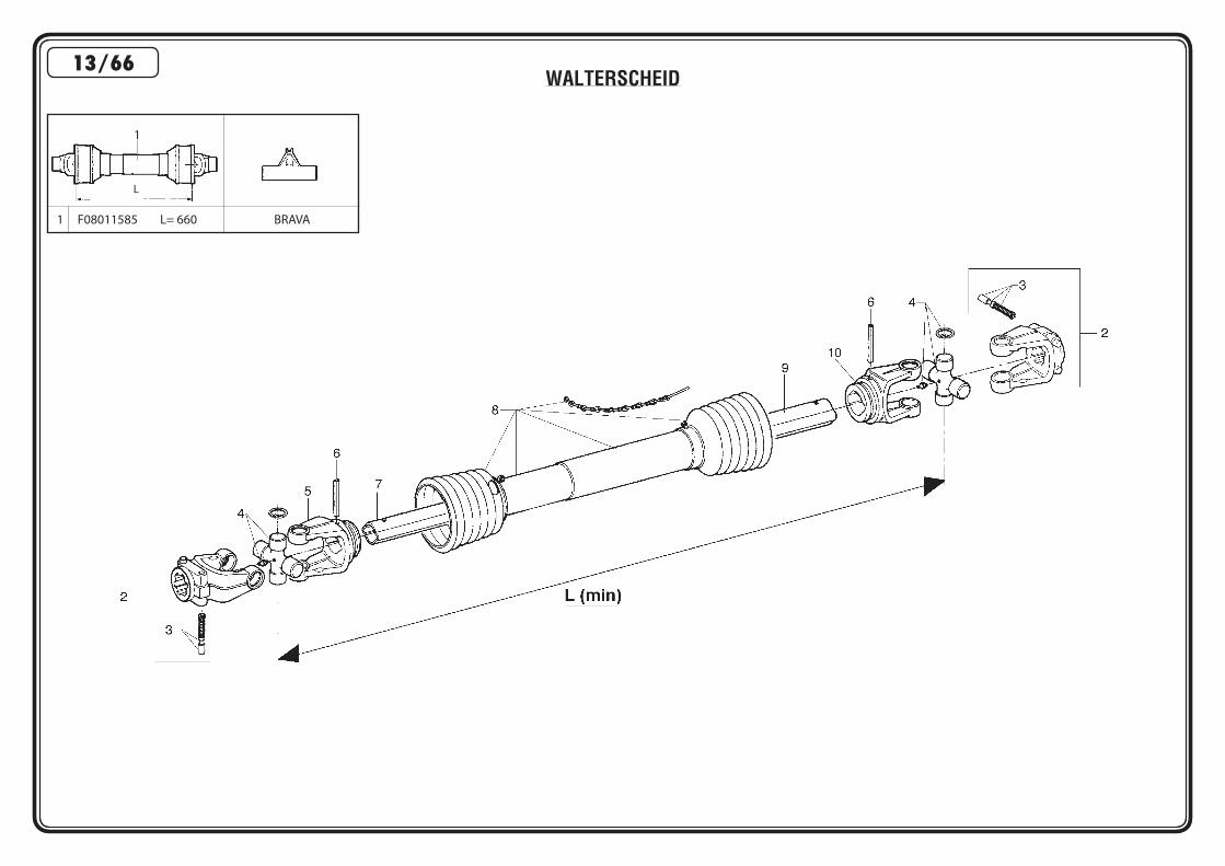
WALTERSCHEID13/66
L
1 F08011585 L= 660 BRAVA
1

POS CODICE DESCRIZIONE DESCRIPTION DESCRIPTION BENENNUNG DESCRIPCION 13/661 F08011585 CARD.GKN 181864 UNIVERSAL P T O SHAFT ARBRE A CARDAN GELENKWELLE ARBOL CARDANICO2 F08010465 FORCELLA COMPLETA DI PULSANTI LINKAGE FORK FOURCHE ATTELAGE GABELSTUECK HORQUILLA ATAQUE3 F08011168 PULSANTE PUSHBUTTON ASSY POUSSOIR COMPL. DRUCKKNOPF KOMPL. PULSADOR COMPL.4 F08010675 CROCIERA COMPLETA SPIDER ASSY CROISIERE COMPL. GELENKKREUZ KOMPL. CRUCETA COMPLETA5 F08010605 FORCELLA PER TUBO INTERNO FORK FOR INTERNAL PIPE FOURCHE TUBE INTERIEUR GABELSTUECK FUER INNENROHR HORQUILLA TUBO INTERIOR6 F02100168 SPINA ELASTICA 10 X 65 DIN1481 ELASTIC PIN 10X75 GOUJON ELASTIQUE 10X75 SPANNHUELSE 10X75 ESPINA ELASTICA 10X757 F08010796 TUBO INTERNO INNER TUBE TUBE PROFILE INTERIEUR PROFILIERTES INNENROHR TUBO PERFILADO INTERNO8 F08010835 PROTEZIONE COMPLETA PROTECTION ASSY PROTECTION COMPL. KOMPL. SCHUTZ PROTECCION COMPL.9 F08010776 TUBO ESTERNO OUTER TUBE TUBE PROFILE EXTERIEUR PROFILIERTES AUSSENROHR TUBO PERFILADO EXTERNO10 F08010615 FORCELLA PER TUBO ESTERNO FORK FOR EXTERNAL PIPE FOURCHE TUBE EXTERIEUR GABELSTUECK FUER AUSSENROHR HORQUILLA TUBO EXTERNO
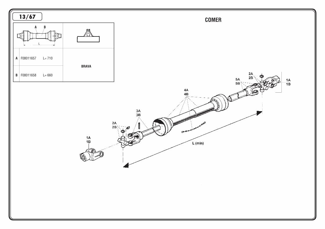
A B
A F08011657 L= 710
BRAVA
B F08011658 L= 660
L
COMER13/67

POS CODICE DESCRIZIONE DESCRIPTION DESCRIPTION BENENNUNG DESCRIPCION 13/67A F08011657 ALBERO CARDANICO COMPLETO UNIVERSAL P T O SHAFT ARBRE A CARDAN GELENKWELLE ARBOL CARDANICOB F08011658 ALBERO CARDANICO COMPLETO UNIVERSAL P T O SHAFT ARBRE A CARDAN GELENKWELLE ARBOL CARDANICO1A F08010471 FORCELLA ATTACCO LINKAGE FORK FOURCHE ATTELAGE GABELSTUECK HORQUILLA ATAQUE1B F08010472 FORCELLA COL.C12 COMPLETA LINKAGE FORK FOURCHE ATTELAGE GABELSTUECK HORQUILLA ATAQUE2A F08010685 CROCIERA COMPLETA SPIDER ASSY CROISIERE COMPL. GELENKKREUZ KOMPL. CRUCETA COMPLETA2B F08010844 CROCERA COMPLETA SPIDER ASSY CROISIERE COMPL. GELENKKREUZ KOMPL. CRUCETA COMPLETA3A F08010575 FORCELLA CON ALBERO FORK WITH SHAFT CUNA FOURCHE AVEC ARBRE CUNA GABELST. + WELL CUNA HORQUILLA + ARBOL CUNA3B F08010578 FORCELLA CON TUBO INTERNO FORK WITH INTERNAL PIPE FOURCHE AVEC TUBE INTERIEUR GABELST. + INNENROHR HORQUILLA + TUBO INTERNO4A F08010849 PROTEZIONE COMPLETA PROTECTION ASSY PROTECTION COMPL. KOMPL. SCHUTZ PROTECCION COMPL.4B F08010888 PROTEZIONE COMPLETA PROTECTION ASSY PROTECTION COMPL. KOMPL. SCHUTZ PROTECCION COMPL.5A F08010527 FORCELLA CON TUBO ESTERNO FORK WITH EXTERNAL PIPE FOURCHE AVEC TUBE EXTERIEUR GABELST. + AUSSENROHR HORQUILLA + TUBO EXTERNO5B F08010532 FORCELLA CON TUBO ESTERNA FORK WITH EXTERNAL PIPE FOURCHE AVEC TUBE EXTERIEUR GABELST. + AUSSENROHR HORQUILLA + TUBO EXTERNO
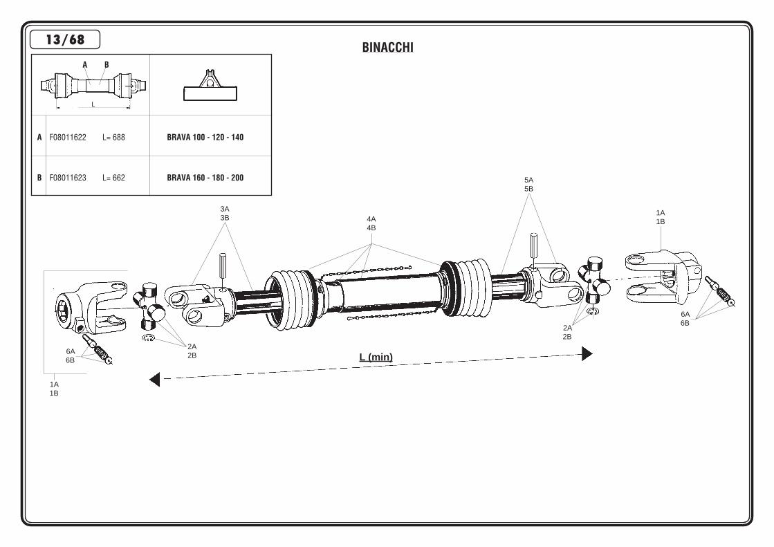
BINACCHI
1A1B
6A6B
2A2B
4A4B
2A2B
L (min)
3A3B
6A6B
5A5B
1A1B
A B
A F08011622 L= 688 BRAVA 100 - 120 - 140
B F08011623 L= 662 BRAVA 160 - 180 - 200
L
13/68

POS CODICE DESCRIZIONE DESCRIPTION DESCRIPTION BENENNUNG DESCRIPCION 13/68A F08011622 CARDANO BINACCHI B4090BA60A60 UNIVERSAL P T O SHAFT ARBRE A CARDAN GELENKWELLE ARBOL CARDANICOB F08011623 CARDANO BINACCHI B6090BA60A60 UNIVERSAL P T O SHAFT ARBRE A CARDAN GELENKWELLE ARBOL CARDANICO1A F08010420 FORCELLA 1 3/8”Z6 BIN.0800403 LINKAGE FORK FOURCHE ATTELAGE GABELSTUECK HORQUILLA ATAQUE1B F08010175 FORCELLA 1 3/8”Z6 BIN.0800603 LINKAGE FORK FOURCHE ATTELAGE GABELSTUECK HORQUILLA ATAQUE2A F08010699 CROCIERA COMPLETA BIN.08204 SPIDER ASSY CROISIERE COMPL. GELENKKREUZ KOMPL. CRUCETA COMPL.2B F08010700 CROCIERA COMPLETA BIN.08206 SPIDER ASSY CROISIERE COMPL. GELENKKREUZ KOMPL. CRUCETA COMPL.3A F08010585 FORCELLA+TUBO INT.BIN.B409001 FORK WITH INTERNAL PIPE FOURCHE AVEC TUBE INT. GABELST. + INNENROHR HORQUILLA + TUBO INT.3B F08010559 FORCELLA + TUBO INT.B.08006011 FORK WITH INTERNAL PIPE FOURCHE AVEC TUBE INT. GABELST. + INNENROHR HORQUILLA + TUBO INT.4A F08010900 PROT.COMP.B4X900 BIN.083B04090 PROTECTION ASSY PROTECTION COMPL. KOMPL. SCHUTZ PROTECCION COMPL.4B F08011125 PROT.COMP.B6X900 BIN.083B06090 PROTECTION ASSY PROTECTION COMPL. KOMPL. SCHUTZ PROTECCION COMPL.5A F08010586 FORCELLA+TUBO EST.BIN.B409002 FORK WITH EXTERNAL PIPE FOURCHE AVEC TUBE EXTERIEUR GABELST. + AUSSENROHR HORQUILLA + TUBO EXTERNO5B F08010489 FORCELLA+TUBO EST.BIN.B409003 FORK WITH EXTERNAL PIPE FOURCHE AVEC TUBE EXTERIEUR GABELST. + AUSSENROHR HORQUILLA + TUBO EXTERNO6A F08011181 PULSANTE CPL 1 3/8 14X47 COMPLETE BUTTON BOUTON COMPLET KOMPL. KNOPF PULSADOR COMPL.6B F08011182 PULSANTE CPL 1 3/8 14X75 COMPLETE BUTTON BOUTON COMPLET KOMPL. KNOPF PULSADOR COMPL.

RICHIEDETE SEMPRE RICAMBI ORIGINALI MARCHIATI GARANZIA DI ASSOLUTA QUALITÀ!USE GENUINE PARTS ONLY, A GUARANTEE OF ABSOLUTE QUALITY!
EXIGEZ LES PIECES DE RECHANGE ESTAMPILLES GARANTIE DE QUALITE ABSOLUEBENUTZEN SIE NUR ORIGINALTEILE MIT DEM EINGEPRÄGTEN DIE GARANTIE FÜR ABSOLUTE QUALITÄT
UTILICEN REPUESTOS ORIGINALES GARANTIA Y FIABILIDAD
La garanzia MASCHIO sulle macchine ha valore solo se utilizzate Ricambi OriginaliMASCHIO Warranty will only cover machines that are fitted with genuine Maschio parts
Les garanties ne s’appliquent que pour les machines équipées de pièces d’origine MASCHIONur der Einsatz von MASCHIO Originalteilen sichert Ihnen die Garantie für Ihre MASCHIO-Geräte
MASCHIO garantíza sus maquinas solo en caso de que esten equipadas con recambios originales
ROTRA MPCLASSIFICAZIONE SAE 85W/140
GR MU EP2
Il grasso AGIP GR MU EP 2 soddisfa le seguenti specifiche:AGIP GR MU EP 2 grease complies with the following specifications:La graisse AGIP GR MU EP 2 satisfait les spécifications suivantes:Das Feet AGIP GR MU EP 2 entspricht den folgenden Normen:La grasa AGIP GR MU EP 2 satisfa los siguientes normas:
- DIN 51825 (KP2K)
L'olio AGIP ROTRA MP soddisfa le seguenti specifiche:AGIP ROTRA MP oil complies with the following specifications:L'huile AGIP ROTRA MP satisfait les spécifications suivantes:Das Öl ROTRA MP entspricht den folgenden Normen:L'aceite AGIP ROTRA MP satisfa los siguientes normas:
- API GL5- MIL-L-2105C
MASCHIO GASPARDO S.p.A.Registered office & Production plantVia Marcello, 73I-35011 Campodarsego (Padova) ItalyTel. +39 049 9289810Fax +39 049 9289900http://www.maschionet.comE-mail: [email protected]
MASCHIO FRANCE S.a.r.l.1, rue de Merignan ZAF-45240 - La Ferte St. Aubin - FranceTel. +33 (0) 2.38.64.12.12Fax +33 (0) 2.38.64.66.79
MASCHIO DEUTSCHLAND GmbHÄußere Nürnberger Straße 5D-91177 ThalmässingDeutschlandTel. +49 (0) 9173 79000Fax +49 (0) 9173 790079
MASCHIO-GASPARDO IBERICA S.L.Calle Cabernet, n° 10Poligono Industrial Clot de MojaOlerdola - 08734 - BarcelonaTel. +34 93 81.99.058Fax +34 93 81.99.059
MASCHIO MIDDLE EASTP.O. Box 922388Amman, 11192 JordanTel. 962 6 5511384Fax 962 6 5538398E-mail: [email protected]
MASCHIO-GASPARDO USA, Inc.120 North Scott Park RoadEldridge, IA 52748 - USAPh. +1 563 - 285 9937Fax +1 563 - 285 9938
Related Documents