YASKAWA YASKAWA AC Drive-Option INSTRUCTIONS MANUAL NO. TOBP C720600 00C Upon receipt of the product and prior to initial operation, read these instructions thoroughly, and retain for future reference. BRAKING UNIT, BRAKING RESISTOR UNIT MODEL: BRAKING UNIT CDBR- BRAKING RESISTOR UNIT LKEB- YASKAWA

Braking Unit Yaskawa - CDBR - 4045B
Aug 26, 2014
Welcome message from author
This document is posted to help you gain knowledge. Please leave a comment to let me know what you think about it! Share it to your friends and learn new things together.
Transcript
YASKAWA
YASKAWA AC Drive-Option
INSTRUCTIONS
MANUAL NO. TOBP C720600 00C
Upon receipt of the product and prior to initial operation, read these instructions thoroughly, and retain for future reference.
BRAKING UNIT, BRAKING RESISTOR UNIT
MODEL: BRAKING UNIT CDBR- BRAKING RESISTOR UNIT LKEB-
YASKAWA
3
PREFACE
Braking resistor unit and braking unit are used to con-sume regenerative energy from motor in the brakingresistor unit at deceleration and to improve the transis-tor inverter braking ability.
Before using the braking resistor unit and braking unit,a thorough understanding of this manual is recom-mended. This instruction manual will be of great helpfor daily maintenance, inspection and troubleshoot-ing.
Inverters to which the braking resistor unit and brakingunit can be connected are of the following series:
D YASKAWA AC Drive 1000 Series
D Varispeed Series
4
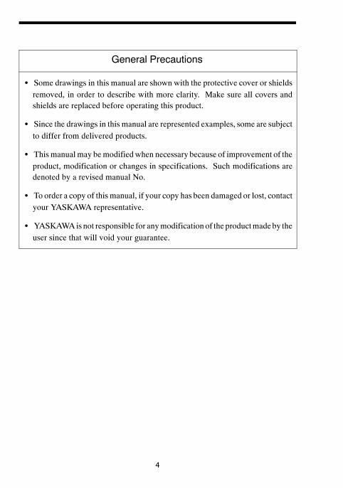
General Precautions
S Some drawings in this manual are shown with the protective cover or shieldsremoved, in order to describe with more clarity. Make sure all covers andshields are replaced before operating this product.
S Since the drawings in this manual are represented examples, some are subjectto differ from delivered products.
S This manual may bemodified when necessary because of improvement of theproduct, modification or changes in specifications. Such modifications aredenoted by a revised manual No.
S To order a copy of this manual, if your copy has been damaged or lost, contactyour YASKAWA representative.
S YASKAWAis not responsible for anymodification of the productmadeby theuser since that will void your guarantee.

NOTE
5
NOTES FOR SAFE OPERATION
Read this instruction manual thoroughly before installation, operation,maintenance or inspection of the braking unit and the braking resistor unit. In thismanual, NOTES FOR SAFE OPERATION are classified as “WARNING” or“CAUTION.”
WARNINGIndicates a potentially hazardous situation which, if not avoided, could result indeath or serious injury to personnel.
CAUTIONIndicates a potentially hazardous situation which, if not avoided, may result in mi-nor or moderate injury to personnel and damage to equipment.It may also be used to alert against unsafe practices.
Even items described in CAUTION may result in a vital accident in somesituations. In either case, follow these important notes.
: These are steps to be taken to insure proper operation.
7
WIRING
WARNING(Ref. page)
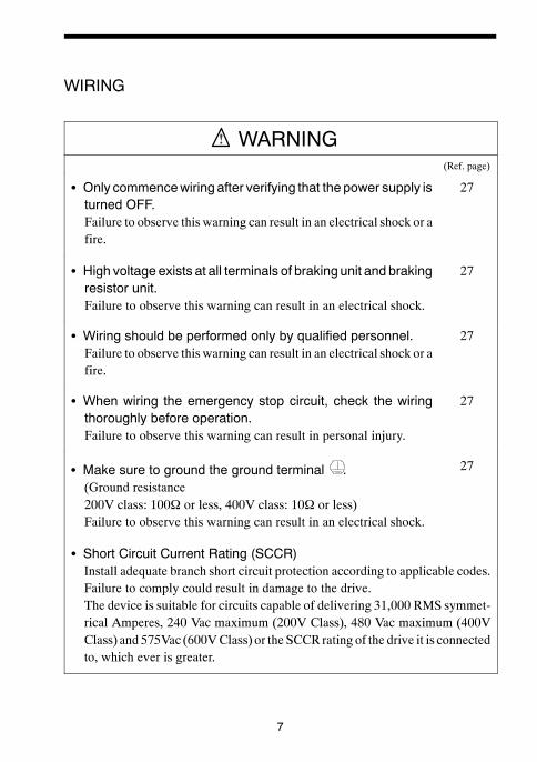
S Only commencewiring after verifying that the power supply isturned OFF.Failure to observe this warning can result in an electrical shock or afire.
27
S High voltage exists at all terminals of braking unit and brakingresistor unit.Failure to observe this warning can result in an electrical shock.
27
S Wiring should be performed only by qualified personnel.Failure to observe this warning can result in an electrical shock or afire.
27
S When wiring the emergency stop circuit, check the wiringthoroughly before operation.Failure to observe this warning can result in personal injury.
27
S Make sure to ground the ground terminal .(Ground resistance200V class: 100Ω or less, 400V class: 10Ω or less)Failure to observe this warning can result in an electrical shock.
27
S Short Circuit Current Rating (SCCR)Install adequate branch short circuit protection according to applicable codes.Failure to comply could result in damage to the drive.The device is suitable for circuits capable of delivering 31,000 RMS symmet-rical Amperes, 240 Vac maximum (200V Class), 480 Vac maximum (400VClass) and 575Vac (600VClass) or the SCCR rating of the drive it is connectedto, which ever is greater.

8
CAUTION(Ref. page)
S Verify that the rated voltageof thebrakingunit and thebrakingresistor unit coincides with the AC power supply voltage.Failure to observe this caution can result in personal injury or a fire.
27
S Donot performawithstand voltage test of the braking unit andbraking resistor unit.It may cause semi−conductor elements to be damaged.
27
S Connect braking resistors, braking resistor units, and brakingunits as shown in the I/Owiring examples. Use properly ratedwire in accordance with table 2 on page 31.Otherwise, a fire can occur.
27
S Tighten terminal screws to the specified tightening torque.Failure to observe this caution can result in a fire.
27
S Be sure to connect braking resistors or braking resistor unitsto the braking units.If neither braking resistor nor braking resistor unit is connected to abraking unit, the fault contact may instantaneously turn ON whenthe power is turned ON, resulting in malfunction of the inverter.
27

9
OPERATION
WARNING(Ref. page)
S Only turn ON the input power supply after replacing the frontcover. Do not remove the cover while current is flowing.Failure to observe this warning can result in an electrical shock.
41
CAUTION(Ref. page)
S Never touch the heatsink or discharging resistor since thetemperature is very high.Failure to observe this caution can result in harmful burns to thebody.
41
S Do not check signals during operation.The machine or the inverter may be damaged.
41
S All theconstantsof thethebrakingunitandthebrakingresistorunit have been preset at the factory. Do not change thesettings unnecessarily.
41

11
CAUTION(Ref. page)
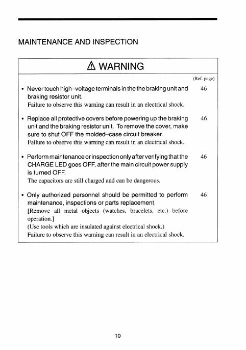
S The control PC board employs CMOS ICs. Do not touch theCMOS elements.They are easily damaged by static electricity.
46
S Donot connectordisconnectwiresorconnectorswhilepoweris applied to the circuit.Failure to observe this caution can result in personal injury.
46
OTHERS
WARNINGS Never modify the product.Failure to observe this warning can result in an electrical shock orpersonal injury and will invalidate the guarantee.

12
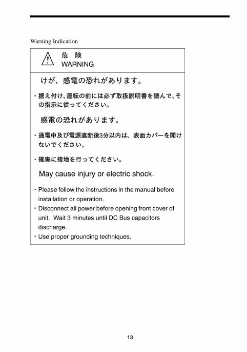
WARNING INDICATION
Awarning label is displayed on the front cover of the braking unit, as shown below.Follow these instructions when handling the braking unit and the braking resistorunit .
ExampleofBrakingUnitModelCDBR−4045B
13


16
2. INSTALLATION
2.1 LOCATION
If the units are temporarily stored or machine stops for an extended length of time,the following precautions should be taken. Store the units at pollution level 2 or less(UL standard) and under the following conditions.
S Free from rainfall and drops of water.
S Clean and dry.
S Free from corrosive gases and liquids.
S Free from dirt and dust.
S Ambient temperature: 14 to 104_F, −10 to 40_C.
S Humidity: 90% RH or less (no condensation)
S Free from vibration.
2.2 INSTALLATION
For full use of the braking resistor unit or braking unit functions, install the unitsat pollution level 2 or less (UL standard) and in a location to satisfy the followingconditions:
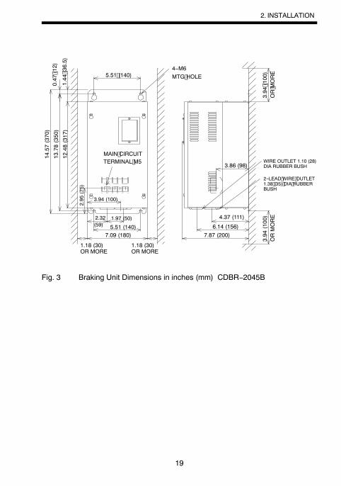
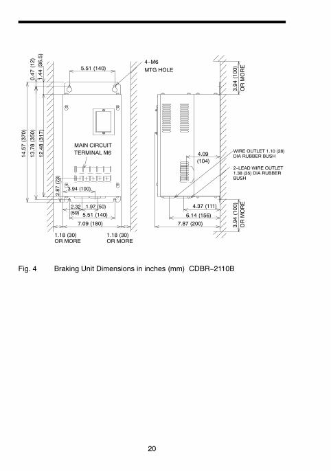
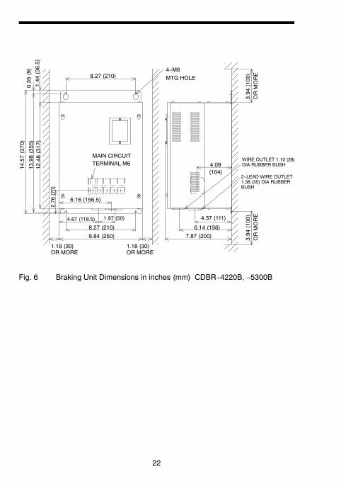
Figs. 1 to 8 show the external dimensions and the spaces from the periphery.
S Provide the spaces shown in Figs. 1 to 8 between the units and the periph-ery.
S Since the braking resistor unit generates heat, provide sufficient spacesfrom devices which are weak against heat.
S Install the units at such locations that all requirements described in Par.2.1 “LOCATION” are satisfied.
17
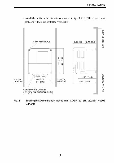
S Install the units in the directions shown in Figs. 1 to 8. There will be noproblem if they are installed vertically.
4−M4 MTG HOLE
1.5 (38)
1.18 (30)OR MORE
3−LEAD WIRE OUTLET[0.87 (20) DIA RUBBER BUSH]
5.04 (128)5.51 (140)
1.5 (38)
2.83 (72) 2.73 (66.5)
4.51 (114.5)
5.45 (138.5)1.18 (30)OR MORE
5.43
(138)
5.91
(150)
3.94(100)ORMORE
3.94(100)ORMORE
Fig. 1 BrakingUnitDimensions in inches (mm) CDBR−2015B,−2022B,−4030B,−4045B
2. INSTALLATION
18
6.57 (167)
3.94
(100)
ORMORE
5.51 (140)
3.94 (100)1.97 (50)
1.18 (30)OR MORE
(58.5)
2.19
(55.5)
11.02(280)
10.23(260)
9.25
(235)
0.39
(10)
1.14
(29)
3.94 (100)
MAIN CIRCUITTERMINAL M4
3−LEAD WIREOUTLET1.10 (28) DIARUBBER BUSH
4−M6MTG HOLE
2.30
1.18 (30)OR MORE
3.94
(100)
ORMORE
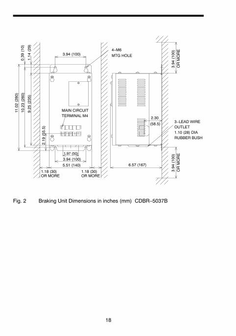
Fig. 2 Braking Unit Dimensions in inches (mm) CDBR−5037B
19
5.51 (140)(59)
7.09 (180)
4.37 (111)
6.14 (156)7.87 (200)
3.86 (98)
3.94 (100)
2.95
(75)
12.48(317)
13.78(350)
14.57(370)
1.44 (36.5)
0.47 (12)
5.51 (140)
MAIN CIRCUITTERMINAL M5
2−LEAD WIRE OUTLET1.38 (35) DIA RUBBERBUSH
4−M6MTG HOLE
3.94 (100)
OR MORE
WIRE OUTLET 1.10 (28)DIA RUBBER BUSH
3.94
(100)
ORMORE2.32 1.97 (50)
1.18 (30)OR MORE
1.18 (30)OR MORE
Fig. 3 Braking Unit Dimensions in inches (mm) CDBR−2045B
2. INSTALLATION
20
MAIN CIRCUITTERMINAL M6
2−LEAD WIRE OUTLET1.38 (35) DIA RUBBERBUSH
4−M6MTG HOLE
3.94
(100)
ORMORE
WIRE OUTLET 1.10 (28)DIA RUBBER BUSH
3.94
(100)
ORMORE
12.48(317)
13.78(350)
14.57(370)
1.44
(36.5)
0.47
(12)
3.94 (100)
2.87
(73)
5.51 (140)
5.51 (140)(59)
7.09 (180)
2.32 1.97 (50)
1.18 (30)OR MORE
1.18 (30)OR MORE
4.37 (111)
6.14 (156)7.87 (200)
4.09(104)
Fig. 4 Braking Unit Dimensions in inches (mm) CDBR−2110B

21
MAIN CIRCUITTERMINAL M5
4−M6MTG HOLE
1.44
(36.5)
0.35
(9)
7.09 (180)12.48(317)
13.98(355)
14.57(370)
5.45 (138.5)
2.95
(75)
8.66 (220)
(68.5) 7.09 (180)2.70 1.97 (50)
1.18 (30)OR MORE
1.18 (30)OR MORE
2−LEAD WIRE OUTLET1.38 (35) DIA RUBBERBUSH
WIRE OUTLET 1.10 (28)DIA RUBBER BUSH
3.94
(100)
ORMORE4.37 (111)
6.14 (156)
7.87 (200)
3.94
(100)
ORMORE
3.86 (98)
Fig. 5 Braking Unit Dimensions in inches (mm) CDBR−4090B, −5110B
2. INSTALLATION
22
MAIN CIRCUITTERMINAL M6
4−M6MTG HOLE
1.44
(36.5)
0.35
(9)
8.27 (210)
12.48(317)
13.98(355)
14.57(370)
2.76
(70)
6.16 (156.5)
8.27 (210)
4.67 (118.5) 1.97 (50)
1.18 (30)OR MORE
9.84 (250)
1.18 (30)OR MORE
2−LEAD WIRE OUTLET1.38 (35) DIA RUBBERBUSH
WIRE OUTLET 1.10 (28)DIA RUBBER BUSH
3.94
(100)
ORMORE4.37 (111)
6.14 (156)7.87 (200)
3.94
(100)
ORMORE
4.09(104)
Fig. 6 Braking Unit Dimensions in inches (mm) CDBR−4220B, −5300B

23
ab b
Braking ResistorUnit Model
Dimensions in inches (mm)Unit Model(LKEB−j) A B C D E
20P7 4.13 (105) 10.83 (275) 1.97 (50) 10.24 (260) M521P5 5.12 (130) 13.78 (350) 2.95 (75) 13.19 (335) M522P2 5.12 (130) 13.78 (350) 2.95 (75) 13.19 (335) M523P7 5.12 (130) 13.78 (350) 2.95 (75) 13.19 (335) M525P5 9.84 (250) 13.78 (350) 7.87 (200) 13.19 (335) M627P5 9.84 (250) 13.78 (350) 7.87 (200) 13.19 (335) M640P7 4.13 (105) 10.83 (275) 1.97 (50) 10.24 (260) M541P5 5.12 (130) 13.78 (350) 2.95 (75) 13.19 (335) M542P2 5.12 (130) 13.78 (350) 2.95 (75) 13.19 (335) M543P7 5.12 (130) 13.78 (350) 2.95 (75) 13.19 (335) M545P5 9.84 (250) 13.78 (350) 7.87 (200) 13.19 (335) M647P5 9.84 (250) 13.78 (350) 7.87 (200) 13.19 (335) M6
Fig. 7 Braking Resistor Unit Dimensions in inches (mm) [for 0.5 to 10HP (0.4 to7.5kW)]
2. INSTALLATION

24
Braking ResistorUnit Model
Dimensions in inches (mm)Unit Model(LKEB−j) A B C D E
2011 10.48 (266) 21.38 (543) 9.69 (246) 13.39 (340) M82015 14.02 (356) 21.38 (543) 13.23 (336) 13.39 (340) M82018 17.56 (446) 21.38 (543) 16.77 (426) 13.39 (340) M82022 17.56 (446) 21.38 (543) 16.77 (426) 13.39 (340) M84011 13.78 (350) 16.22 (412) 12.99 (330) 12.80 (325) M64015 13.78 (350) 16.22 (412) 12.99 (330) 12.80 (325) M64018 17.56 (446) 21.38 (543) 16.77 (426) 13.39 (340) M84022 17.56 (446) 21.38 (543) 16.77 (426) 13.39 (340) M84030 14.02 (356) 37.64 (956) 13.23 (336) 29.13 (740) M84037 17.56 (446) 37.64 (956) 16.77 (426) 29.13 (740) M84045 17.56 (446) 37.64 (956) 16.77 (426) 29.13 (740) M8
Fig. 8 Braking Resistor Unit Dimensions in inches (mm) [for 15 to 60HP (11 to45kW)]
25
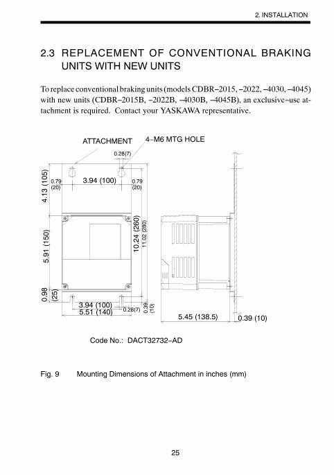
2.3 REPLACEMENT OF CONVENTIONAL BRAKINGUNITS WITH NEW UNITS
To replace conventional braking units (modelsCDBR−2015,−2022,−4030,−4045)with new units (CDBR−2015B, −2022B, −4030B, −4045B), an exclusive−use at-tachment is required. Contact your YASKAWA representative.
0.39(10)0.28(7)
3.94 (100)
11.02(280)
5.51 (140)
10.24(260)
ATTACHMENT
5.45 (138.5) 0.39 (10)
0.98(25)
5.91(150)
4.13(105)
4−M6 MTG HOLE
Code No.: DACT32732−AD
3.94 (100)0.79(20)
0.28(7)
0.79(20)
Fig. 9 Mounting Dimensions of Attachment in inches (mm)
2. INSTALLATION

26
The main circuit terminal symbols are different between conventional models andnew models. Refer to the following table.
Table 1 Main Circuit Terminal Symbols
Conventional Models New Models
N ©
P ¨
P0 ¨0
B ©0
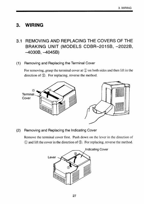
28
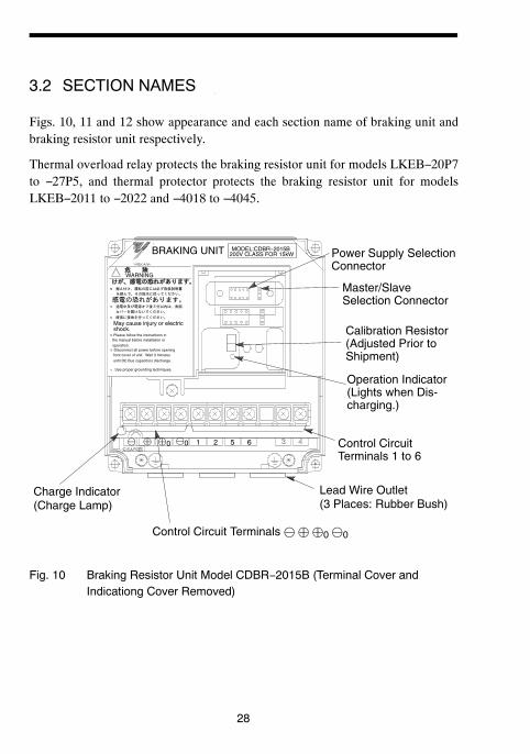
3.2 SECTION NAMES
Figs. 10, 11 and 12 show appearance and each section name of braking unit andbraking resistor unit respectively.
Thermal overload relay protects the braking resistor unit for models LKEB−20P7to −27P5, and thermal protector protects the braking resistor unit for modelsLKEB−2011 to −2022 and −4018 to −4045.
Use proper grounding techniques.
MODEL:CDBR−2015B
1 2 5 6© ¨ ¨0 ©0
200V CLASS FOR 15kWBRAKING UNIT
WARNING
May cause injury or electric
Please follow the instructions inthe manual before installation or
operation.
shock.
Disconnect all power before openingfront cover of unit. Wait 3 minutes
until DC Bus capacitors discharge.
Lead Wire Outlet(3 Places: Rubber Bush)
Charge Indicator(Charge Lamp)
Master/SlaveSelection Connector
Operation Indicator(Lights when Dis-charging.)
Control CircuitTerminals 1 to 6
Control Circuit Terminals © ¨ ¨0 ©0
Calibration Resistor(Adjusted Prior toShipment)
Power Supply SelectionConnector
Fig. 10 Braking Resistor Unit Model CDBR−2015B (Terminal Cover andIndicationg Cover Removed)
29
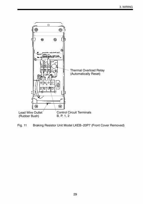
Thermal Overload Relay(Automatically Reset)
Control Circuit TerminalsB, P, 1, 2
Lead Wire Outlet(Rubber Bush)
Fig. 11 Braking Resistor Unit Model LKEB−20P7 (Front Cover Removed)
3.WIRING
30
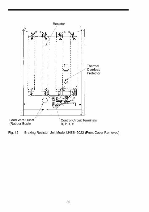
Resistor
ThermalOverloadProtector
Control Circuit TerminalsB, P, 1, 2
Lead Wire Outlet(Rubber Bush)
Fig. 12 Braking Resistor Unit Model LKEB−2022 (Front Cover Removed)

31
3.3 CIRCUITS AND WIRING SPECIFICATIONS
Table 2 Circuits and Wiring Specifications
Name Circuit Termi-nals
WireSizeAWG(mm2)
Wire Type TerminalScrew
Max.Torquelb⋅in(N⋅m)
Braking Unit(Models CDBR2015B 2022B
Main ¨ ¨0© ©0
12−10(3.5−5.5)
M413.3(
−2015B, −2022B,−4030B, −4045B,−5037B)
Con-trol
1 2 34 5 6
18−14(0.75−2)
M413.3(1.50)
Braking Unit(Model CDBR
Main ¨ ¨0© ©0
10−8(5.5−8) 600V
(Hi h
M521.7(2.45)(Model CDBR
−2045B, −4090B,−5110B)
Con-trol
1 2 34 5 6
18−14(0.75−2)
(HighVoltage)*3vinyl
M415.6(1.76)
Braking Unit(ModelCDBR 2110B
Main ¨ ¨0© ©0
4 (22)8−6
(8−14)*1
vinylsheathedwire orequivalent
M643.4(4.90)(
CDBR−2110B,−4220B, −5300B)
Con-trol
1 2 34 5 6
18−14(0.75−2)
equivalent
M415.6(1.76)
Braking ResistorUnit Main B P 12−10
(3.5−5.5)M4
(M5) *215.6 (1.76)(21.7(2.45))
(Model LKEB−j)
Con-trol 1 2 18−14
(0.75−2) M4 15.6 (1.76)
*1 For wire size of 8−6 (8−14), use UL1283 heat−resistant vinyl−insulated wire orequivalent.
*2 M4 for Models LKEB−20P7 to −27P5 or −40P7 to −4015.M5 for Models LKEB−2011 to −2022 or −4018 to −4045.
*3 Models−5037B, −5100B, and −5300B can reach an operating voltage of 1040 VDC.Please select wire which is suitable for the operating voltage.
3.WIRING
32
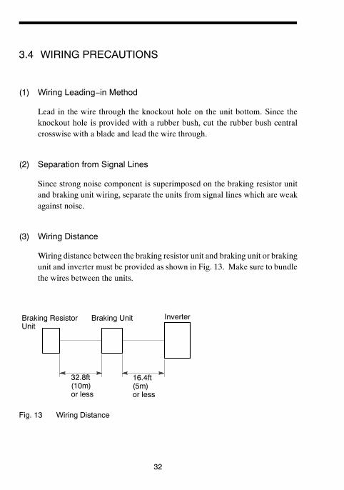
3.4 WIRING PRECAUTIONS
(1) Wiring Leading−in Method
Lead in the wire through the knockout hole on the unit bottom. Since theknockout hole is provided with a rubber bush, cut the rubber bush centralcrosswise with a blade and lead the wire through.
(2) Separation from Signal Lines
Since strong noise component is superimposed on the braking resistor unitand braking unit wiring, separate the units from signal lines which are weakagainst noise.
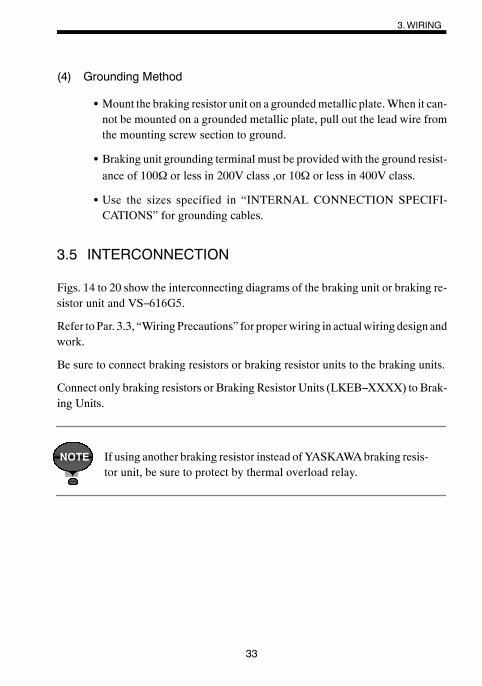
(3) Wiring Distance
Wiring distance between the braking resistor unit and braking unit or brakingunit and inverter must be provided as shown in Fig. 13. Make sure to bundlethe wires between the units.
Braking ResistorUnit
Braking Unit Inverter
32.8ft(10m)or less
16.4ft(5m)or less
Fig. 13 Wiring Distance
3.WIRING
33
(4) Grounding Method
S Mount the braking resistor unit on a groundedmetallic plate.When it can-not be mounted on a grounded metallic plate, pull out the lead wire fromthe mounting screw section to ground.
S Braking unit grounding terminal must be provided with the ground resist-ance of 100Ω or less in 200V class ,or 10Ω or less in 400V class.
S Use the sizes specified in “INTERNAL CONNECTION SPECIFI-CATIONS” for grounding cables.
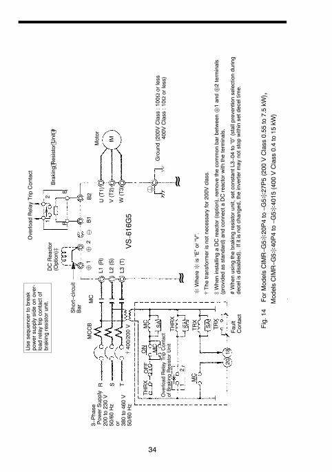
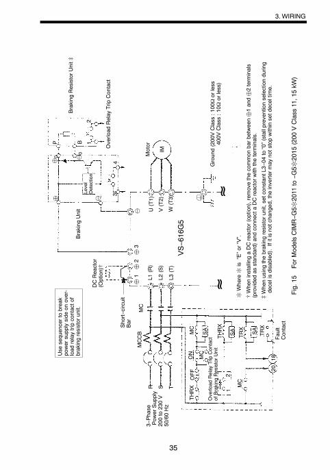
3.5 INTERCONNECTION
Figs. 14 to 20 show the interconnecting diagrams of the braking unit or braking re-sistor unit and VS−616G5.
Refer to Par. 3.3, “WiringPrecautions” for properwiring in actualwiring design andwork.
Be sure to connect braking resistors or braking resistor units to the braking units.
Connect only braking resistors or Braking Resistor Units (LKEB−XXXX) to Brak-ing Units.
If using another braking resistor instead ofYASKAWAbraking resis-tor unit, be sure to protect by thermal overload relay.
NOTE
34
¨1
VS− 616G5
R
MC
S T
THRX
OFF
ON
MC
SA
12
MC
TRX
TRX
2018
¨2
B1
B2
SA
SA
THRX
U(T1)
V(T2)
W(T3)
IM
12
BP
MC
©
Fig.14
ForM
odelsCIMR−G
5:20P4to−G
5:27P5(200
VClass
0.55
to7.5kW
) ,ModelsCIMR−G
5:40P4to−G
5:4015
(400
VClass
0.4to15
kW)
≈≈
Motor
Overload
Relay
TripContact
Braking Resistor Unit #
Ground(200VClass
:100
Ωorless
400V
Class
:10Ω
orless)
3−Phase
Pow
erSupply
200to230V
50/60Hz
or 380to460V
50/60Hz
L1(R)
L2(S)
L3(T)
[400/200V
Overload
Relay
TripContact
ofBraking
ResistorUnit
Fault
Contact
DCReactor
(Option)]
Short−circuit
Bar
Use
sequencertobreak
powersupplyside
onover-
load
relaytripcontactof
brakingresistorunit.
[The
transformerisnotnecessaryfor200V
class.
:Where:
is“E”or“V”.
]WheninstallingaDCreactor(option),rem
ovethecommon
barbetween¨1and¨2terminals
(providedas
standard)andconnecta
DCreactorwith
theterminals.
#Whenusingthebrakingresistorunit,setconstantL3−04
to“0”(stallpreventionselectionduring
decelisdisabled).Ifitisnotchanged,the
invertermay
notstopwithinsetdeceltim
e.
MCCB
35
U(T1)
© V(T2)
W(T3)
MC
S T
THRX
OFF
ON
MC
SA
12
MC
TRX
TRX
2018
SA SA
THR
X
IM
¨1
¨2¨
3
P¨0 ©0
12
34
VS−616G5
MC
≈≈
¨ ©
Motor
Braking
ResistorUnit]
Ground(200VClass
:100
Ωorless
400V
Class
:10Ω
orless)
L1(R)
L2(S)
L3(T)
Use
sequencertobreak
powersupplyside
onover-
load
relaytripcontactof
brakingresistorunit.
Overload
Relay
TripContact
ofBraking
ResistorUnit
Fault
ContactShort−circuit
Bar
MCCB
Overload
Relay
TripContact
DCReactor
(Option)[
Level
Detection
Braking
Unit
:Where:
is“E”or“V”.
]Whenusingthebrakingresistorunit,setconstantL3−04
to“0”(stallpreventionselectionduring
decelisdisabled).Ifitisnotchanged,the
invertermay
notstopwithinsetdeceltim
e.
[WheninstallingaDCreactor(option),rem
ovethecommon
barbetween¨1and¨2terminals
(providedas
standard)andconnecta
DCreactorwith
theterminals.
Fig.15
ForM
odelsCIMR−G
5:2011
to−G
5:2015
(200
VClass
11,15kW
)
R
B
3−Phase
Pow
erSupply
200to230V
50/60Hz
3.WIRING
36
©
RMC
S T
MTHRX
OFF
ON
MC
SA
12
MC
TRX
TR
X
2018
SA
SA
THR
IM
¨1
¨2¨
3
P 12
34
VS−616G5
B
MC
≈≈
¨0 ©0
¨ ©
Overload
Relay
TripContact
Level
Detection
Braking
Unit
Motor
Ground(200VClass
:100
Ωorless
400V
Class
:10Ω
orless)
L1(R)
L2(S)
L3(T)
MCCB
Use
sequencertobreak
powersupplyside
onover-
load
relaytripcontactof
brakingresistorunit.
3−Phase
Pow
erSupply
200to230V
50/60Hz
Overload
Relay
TripContact
ofBraking
ResistorUnit
Fault
Contact
Braking
Resistor
Unit(Option)[
Short−circuitBar
(Providedas
Standard)
CoolingFan
:Where:
is“E”or“V”.
[Whenusingthebrakingresistorunit,setconstantL3−04
to“0”(stallpreventionselectionduring
decelisdisabled).Ifitisnotchanged,the
invertermay
notstopwithinsetdeceltim
e.
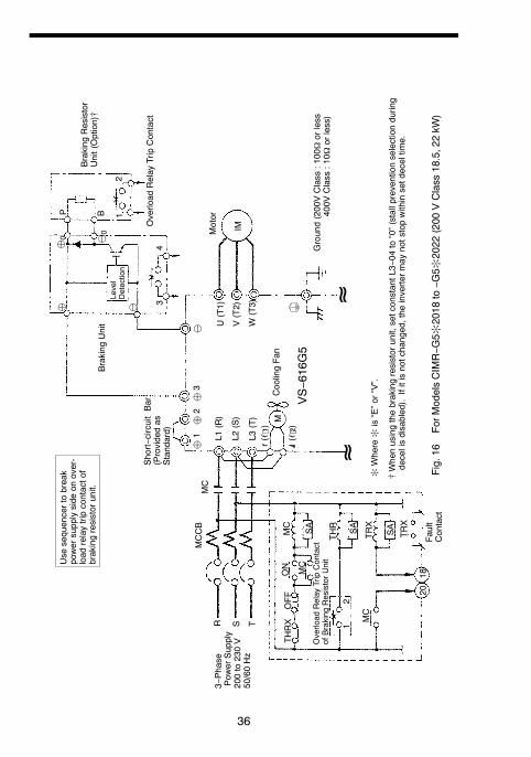
Fig.16
ForM
odelsCIMR−G
5:2018
to−G
5:2022
(200
VClass
18.5,22kW
)
(ℓ 2)
r(ℓ 1)
U(T1)
V(T2)
W(T3)
37
©
RMC
S T
THRX
OFF
ON
MC
SA
12
MC
TRX
TRX
2018
SA
SA
THRX
IM
VS−616G5
M
¨1
¨2¨
3
P 12
34
B
MC
≈≈
¨0 ©0
¨ ©
Overload
Relay
TripContact
Level
Detection
Braking
Unit
Braking
Resistor
Unit(Option)[
Motor
Ground(200VClass
:100
Ωorless
400V
Class
:10Ω
orless)
CoolingFan
L1(R)
L2(S)
L3(T)
Short−circuitBar
(Providedas
Standard)
(ℓ 2)
r(ℓ 1)
MCCB
Use
sequencertobreak
powersupplyside
onover-
load
relaytripcontactof
brakingresistorunit.
3−Phase
Pow
erSupply
380to460V
50/60Hz
Overload
Relay
TripContact
ofBraking
ResistorUnit
Fault
Contact
:Where:
is“E”or“V”.
[Whenusingthebrakingresistorunit,setconstantL3−04
to“0”(stallpreventionselectionduring
decelisdisabled).Ifitisnotchanged,the
invertermay
notstopwithinsetdeceltim
e.
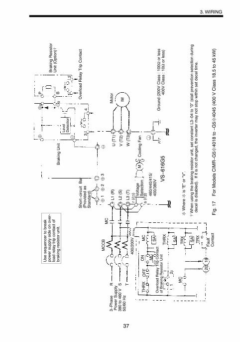
Fig.17
ForM
odelsCIMR−G
5:4018
to−G
5:4045
(400
VClass
18.5to45
kW)
Voltage
Selection
460/440/415/
400/380V
400/200V
U(T1)
V(T2)
W(T3)
3.WIRING

38
©
RMC
S T400/200V
M
VS−616G5
¨3
IM
THRX
OFF
ON
MC
SA
12
MC
TRX
TRX
2018
SA SA
THRX
MC
P B 12
34
≈≈
Overload
Relay
TripContact
(ThermalProtectorContact:
230VAC,1Aorless)
Level
Detection
Braking
Unit
Braking
Resistor
Unit(Option)[
CoolingFan
r(ℓ 1) Voltage
Selection
Motor
Ground(200VClass
:100
Ωorless
400V
Class
:10Ω
orless)
MCCB
Use
sequencertobreak
powersupplyside
onover-
load
relaytripcontactof
brakingresistorunit.
3−Phase
Pow
erSupply
380to460V
50/60Hz
Overload
Relay
TripContact
ofBraking
ResistorUnit
Fault
Contact
400(ℓ 2 400)
:Where:
is“E”or“V”.
[Whenusingthebrakingresistorunit,setconstantL3−04
to“0”(stallpreventionselectionduringdecelisdisabled).
Ifitisnotchanged,the
invertermay
notstopwithinsetdeceltim
e.
Fig.18
ForM
odelsCIMR−G
5:4055
to−G
5:4160
(400
VClass
55to160kW
)
CoolingFinOverheatContact
(ThermoswitchContact:
250VAC,1Aorless
30VDC,1Aorless)
U(T1)
V(T2)
W(T3)
L1(R)
L2(S)
L3(T)
¨0
©0
¨ ©
460/440/415/
400/380V

39
©
R
MC
S T
IM
M
¨3 VS−616G5
THRX
OFF
ON
MC
SA
12
MC
TRX
TRX
2018
SA
SA
THRX
P
34
B 12
MC
≈≈
U(T1)
V(T2)
W(T3)
Overload
Relay
TripContact
(ThermalProtectorContact:
230VAC,1Aorless)
Braking
Resistor
Unit(Option)[
Motor
Ground(200VClass
:100
Ωorless
400V
Class
:10Ω
orless)
CoolingFinOverheatContact
(ThermoswitchContact:
250VAC,1Aorless
30VDC,1Aorless)
Level
Detection
Braking
Unit
CoolingFan
r(ℓ 1)
MCCB
L1(R)
L2(S)
L3(T)
Use
sequencertobreak
powersupplyside
onover-
load
relaytripcontactof
brakingresistorunit.
Overload
Relay
TripContact
ofBraking
ResistorUnit
Fault
Contact
(ℓ 2)
3−Phase
Pow
erSupply
200to230V
50/60Hz
[Whenusingthebrakingresistorunit,setconstantL3−04
to“0”(stallpreventionselectionduringdecelisdisabled).
Ifitisnotchanged,the
invertermay
notstopwithinsetdeceltim
e.
:Where:
is“E”or“V”.
Fig.19
ForM
odelsCIMR−G
5:2030
to−G
5:2075
(200
VClass
30to75
kW)
¨0
©0
¨ ©
3.WIRING

40
©
RMC
S T400/200V
M
VS−616G5
¨3
IM
¨1
THRX
OFF
ON
MC
SA
12
MC
TRX
TRX
2018
SA
SA
THRX
MC
P
34
B 12
≈≈
U(T1)
V(T2)
W(T3)
Overload
Relay
TripContact
(ThermalProtectorContact:
230VAC,1Aorless)
Braking
Resistor
Unit(Option)[
Motor
Ground(200VClass
:100
Ωorless
400V
Class
:10Ω
orless)
CoolingFinOverheatContact
(ThermoswitchContact:
250VAC,1Aorless
30VDC,1Aorless)
Level
Detection
Braking
Unit
CoolingFan
L1(R)
L2(S)
L3(T)
r(ℓ 1)
MCCB
Use
sequencertobreak
powersupplyside
onover-
load
relaytripcontactof
brakingresistorunit.
Voltage
Selection
400(ℓ 2 400)
3−Phase
Pow
erSupply
380to460V
50/60Hz
Overload
Relay
TripContact
ofBraking
ResistorUnit
Fault
Contact
[Whenusingthebrakingresistorunit,setconstantL3−04
to“0”(stallpreventionselectionduringdecelisdisabled).
Ifitisnotchanged,the
invertermay
notstopwithinsetdeceltim
e.
:Where:
is“E”or“V”.
Fig.20
ForM
odelsCIMR−G
5:4185
to−G
5:4220
(400
VClass
185to220kW
)
¨0
©0
¨ ©
460/440/415/
400/380V
41
4. OPERATION
4.1 ADJUSTMENT
The braking resistor unit and braking unit do not have to be adjusted.
Especially, do not readjust the braking unit except in the case described in Par. 4.2,“Power Supply Voltage Selection Connector Setting.”
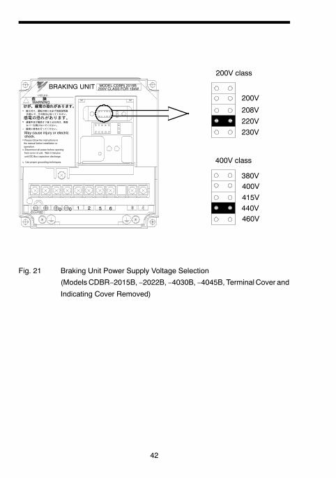
4.2 POWER SUPPLY VOLTAGE SELECTION CON-NECTOR SETTING
It may be necessary to select power supply voltage selection connector for brakingunit according to main circuit power supply type. Table 3 shows the relationshipbetween the power supply voltage selection connector and braking start voltage.
The following is the setting prior to shipment:
S 200V class : 220V
S 400V class : 440V
S 575V class : 575V
For removing the terminal cover and the indicating cover, refer to Par. 3.1.
4.OPERATION
42
200V
208V220V230V
400V415V440V460V
380V
200V class
400V class
1 2 5 6
May cause injury or electric
WARNING
Please follow the instructions inthe manual before installation or
operation.
shock.
Disconnect all power before openingfront cover of unit. Wait 3 minutes
until DC Bus capacitors discharge.
Use proper grounding techniques.
MODEL:CDBR( 2015B200V CLASS FOR 15kWBRAKING UNIT
¨© ¨0 ©0
Fig. 21 Braking Unit Power Supply Voltage Selection
(Models CDBR−2015B, −2022B, −4030B, −4045B, Terminal Cover and
Indicating Cover Removed)
43
200V
208V220V230V
400V415V440V460V
380V
500V
575V
575V class
200V class 400V class
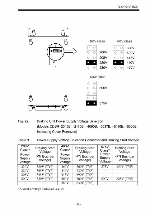
Fig. 22 Braking Unit Power Supply Voltage Selection
(Models CDBR−2045B, −2110B, −4090B, −5037B, −5110B, −5300B,
Indicating Cover Removed)
Table 3 Power Supply Voltage Selection Connector and Braking Start Voltage
200VClass*PowerSupplyVoltage
Braking StartVoltage
(PN Bus−barVoltage)
400VClass*PowerSupplyVoltage
Braking StartVoltage
(PN Bus−barVoltage)
575VClass*PowerSupplyVoltage
Braking StartVoltage
(PN Bus−barVoltage)
230V 380V (TYP) 460V 760V (TYP) 575V 950V (TYP)220V 365V (TYP) 440V 730V (TYP) − −208V 345V (TYP) 415V 690V (TYP) − −200V 330V (TYP) 400V 660V (TYP) 500V 825V (TYP)− − 380V 630V (TYP) − −
*Allowable voltage fluctuation is ±10%
4.OPERATION
44
4.3 MASTER/SLAVESELECTIONCONNECTORSETTING
Selection Connector Setting MASTER side is selected prior to shipment. Use theunits without changing the setting.
SLAVE side is selected when more than one braking unit is combined to use andbraking start levels must coincide. Refer to Par. 4.4, “Parallel Connection of Brak-ing Unit” for details.
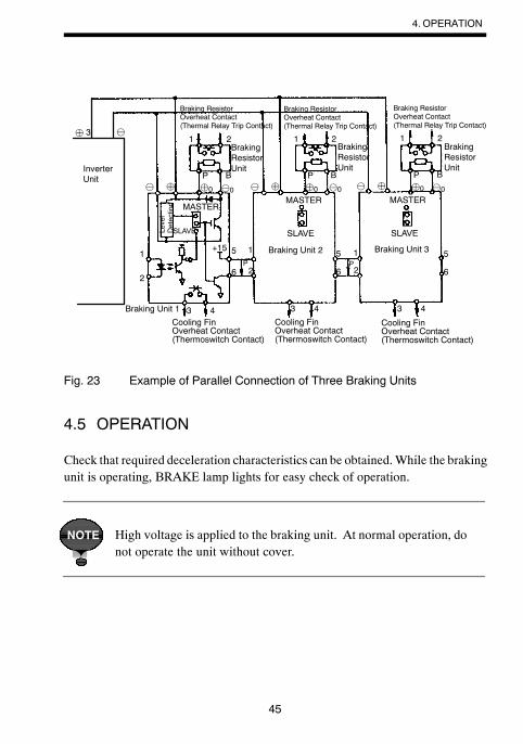
4.4 PARALLEL CONNECTION OF BRAKING UNIT
For using more than one parallel−connected braking unit, connect and select theconnectors as follows. (See Fig. 23.)
S Braking units have a MASTER/SLAVE selection connector. (See Fig.10.) Select MASTER side only for braking unit 1 and select SLAVE sidefor braking units 2 and 3.
S Connect thermal protector on the braking resistor unit and thermoswitchon the braking unit in parallel. Refer to Figs. 15 and 18 for proper wiring.
S Use properly rated wire in accordance with table 2 on page 31.
S Use twisted−pair wires of 1mm or less for connection between 5, 6 and1, 2 of the braking units.
S Parallel connection of braking unit is possible up to a maximum of 10units.
45
1 2
P¨
1
2
4
B
MASTER
SLAVE
3
5 1
26P
+15
MASTER
SLAVE
¨ 3 ©
5 1
26P
© ¨0 ©0
43 43
5
6
MASTER
SLAVE
1 2
P¨
B© ¨0 ©0
1 2
P¨
B© ¨0 ©0
Braking ResistorOverheat Contact(Thermal Relay Trip Contact)
Braking ResistorOverheat Contact(Thermal Relay Trip Contact)
Braking ResistorOverheat Contact(Thermal Relay Trip Contact)
BrakingResistorUnit
BrakingResistorUnit
BrakingResistorUnitInverter
Unit
Level
Detection
Braking Unit 2 Braking Unit 3
Braking Unit 1
Cooling FinOverheat Contact(Thermoswitch Contact)
Cooling FinOverheat Contact(Thermoswitch Contact)
Cooling FinOverheat Contact(Thermoswitch Contact)
Fig. 23 Example of Parallel Connection of Three Braking Units
4.5 OPERATION
Check that required deceleration characteristics can be obtained.While the brakingunit is operating, BRAKE lamp lights for easy check of operation.
High voltage is applied to the braking unit. At normal operation, donot operate the unit without cover.
NOTE
4.OPERATION
46
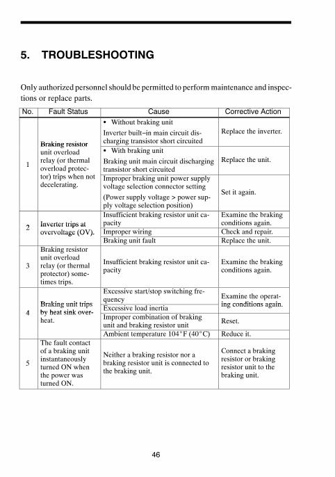
5. TROUBLESHOOTING
Only authorized personnel should be permitted to performmaintenance and inspec-tions or replace parts.
No.
Fault Status
Cause
Corrective Action
Braking resistor
S Without braking unitInverter built−in main circuit dis-charging transistor short circuited
Replace the inverter.
1
Braking resistorunit overloadrelay (or thermaloverload protec-) i h
S With braking unitBraking unit main circuit dischargingtransistor short circuited
Replace the unit.
ptor) trips when notdecelerating.
Improper braking unit power supplyvoltage selection connector setting(Power supply voltage > power sup-ply voltage selection position)
Set it again.
2
Inverter trips at
Insufficient braking resistor unit ca-pacity
Examine the brakingconditions again.
2Inverter trips atovervoltage (OV).
Improper wiring
Check and repair.
overvoltage (OV).
Braking unit faultReplace the unit.
3
Braking resistorunit overloadrelay (or thermalprotector) some-times trips.
Insufficient braking resistor unit ca-pacity
Examine the brakingconditions again.
Braking unit trips
Excessive start/stop switching fre-quency
Examine the operat-ing conditions again
4
Braking unit tripsby heat sink over-
Excessive load inertia
ing conditions again.
4by heat sink over-heat.
Improper combination of brakingunit and braking resistor unit
Reset.
Ambient temperature 104_F (40_C)
Reduce it.
5
The fault contactof a braking unitinstantaneouslyturned ON whenthe power wasturned ON.
Neither a braking resistor nor abraking resistor unit is connected tothe braking unit.
Connect a brakingresistor or brakingresistor unit to thebraking unit.

6.SPECIFICATIONS
47
6. SPECIFICATIONS
6.1 BRAKING UNIT AND BRAKING RESISTOR UNITAPPLICATION LIST
The applicable braking unit and braking resistor unitmodels differ depending on theinverter model. Refer to the catalog of the relevant inverter.
Example: 200−V Class Inverter Model CIMR−G5j
Inverter Braking Unit Braking Resistor Unit Approx.Braking
Max ApplicableMotor Capacity
HP(kW)
Model(CDBR−j)
UnitQ’ty
Model(LKEB−j)
Resistor Spec.(per unit)
UnitQ’ty
BrakingTorque(10%ED)
%0.5 (0.4) − − 20P7 70W 200Ω 1 2201 (0.75) − − 20P7 70W 200Ω 1 1252 (1.5) − − 21P5 260W 100Ω 1 1253 (2.2) − − 22P2 260W 70Ω 1 1205 (3.7) − − 23P7 390W 40Ω 1 1257.5 (5.5) − − 25P5 520W 30Ω 1 11510 (7.5) − − 27P5 780W 20Ω 1 12515 (11) 2015B 1 2011 2400W 13.6Ω 1 12520 (15) 2015B 1 2015 3000W 10Ω 1 12525 (18.5) 2022B 1 2018 4800W 8Ω 1 12530 (22) 2022B 1 2022 4800W 6.8Ω 1 12540 (30) 2015B 2 2015 3000W 10Ω 2 12550 (37) 2015B 2 2015 3000W 10Ω 2 10060 (45) 2022B 2 2022 4800W 6.8Ω 2 12075 (55) 2022B 2 2022 4800W 6.8Ω 2 100100 (75) 2110B 1 2022 4800W 6.8Ω 3 110120 (90) 2110B 1 2022 4800W 6.8Ω 4 120150 (110) 2110B 1 2022 4800W 6.8Ω 5 100
Note: The above table lists the applicable braking unit and braking resistor unitmodels for the 200−Vclassinverter model CIMR−G5j. For other inverter models, refer to the catalog of the relevant inverter.

48
Example: 400−V Class Inverter Model CIMR−G5j
Inverter Braking Unit Braking Resistor Unit Approx.Braking
Max ApplicableMotor Capacity
HP(kW)
Model(CDBR−j)
UnitQ’ty
Model(LKEB−j)
Resistor Spec.(per unit)
UnitQ’ty
BrakingTorque(10%ED)
%
0.5 (0.4) − − 40P7 70W 750Ω 1 2301 (0.75) − − 40P7 70W 750Ω 1 1302 (1.5) − − 41P5 260W 400Ω 1 1253 (2.2) − − 42P2 260W 250Ω 1 1355 (3.7) − − 43P7 390W 150Ω 1 1357.5 (5.5) − − 45P5 520W 100Ω 1 13510 (7.5) − − 47P5 780W 75Ω 1 13015 (11) − − 4011 1040W 50Ω 1 13520 (15) − − 4015 1560W 40Ω 1 12525 (18.5) 4030B 1 4018 4800W 32Ω 1 12530 (22) 4030B 1 4022 4800W 27.2Ω 1 12540 (30) 4030B 1 4030 6000W 20Ω 1 12550 (37) 4045B 1 4037 9600W 16Ω 1 12560 (45) 4045B 1 4045 9600W 13.6Ω 1 12575 (55) 4030B 2 4030 6000W 20Ω 2 135100 (75) 4045B 2 4045 9600W 13.6Ω 2 145150 (110) 4030B 3 4030 6000W 20Ω 3 100200 (160) 4220B 1 4045 9600W 13.6Ω 4 140300 (220) 4220B 1 4037 9600W 16Ω 5 110400 (300) 4220B 2 4045 9600W 13.6Ω 6 110800 (600) 4220B 4 4045 9600W 13.6Ω 12 110
Note: The above table lists the applicable braking unit and braking resistor unitmodels for the 400−Vclassinverter model CIMR−G5j. For other inverter models, refer to the catalog of the relevant inverter.

6.SPECIFICATIONS
49
6.2 BRAKING UNIT FOR 575V CLASS APPLICATION LIST
Example: 575−V Class Inverter Model CIMR−G5j
Inverter Braking Unit Braking Resistor Unit Approx.Braking
Max ApplicableMotor Capacity
HP(kW)
Model(CDBR−j)
Unit Q’ty Resistor Spec.
BrakingTorque
(10%ED)
%5 (3.7) − − 560W 150Ω 1807.5 (5.5) − − 560W 150Ω 12510 (7.5) − − 750W 100Ω 14015 (11) − − 1100W 75Ω 12520 (15) − − 1500W 50Ω 14025 (18.5) − − 2300W 40Ω 14030 (22) 5037B 1 2800W 38Ω 12540 (30) 5037B 1 3900W 33Ω 11050 (37) 5037B 1 4900W 27Ω 11060 (45) 5037B 2 5900W 22Ω 11075 (55) 5037B 2 7200W 18Ω 110100 (75) 5110B 1 9800W 13.6Ω 105120 (90) 5110B 1 12000W 11Ω 110150 (110) 5110B 1 15000W 9Ω 110200 (160) 5300B 1 21000W 6.8Ω 100
Note: The above table lists the applicable braking unit and braking resistor unitmodels for the 575−Vclassinverter model CIMR−G5j. For other inverter models, refer to the catalog of the relevant inverter.
50
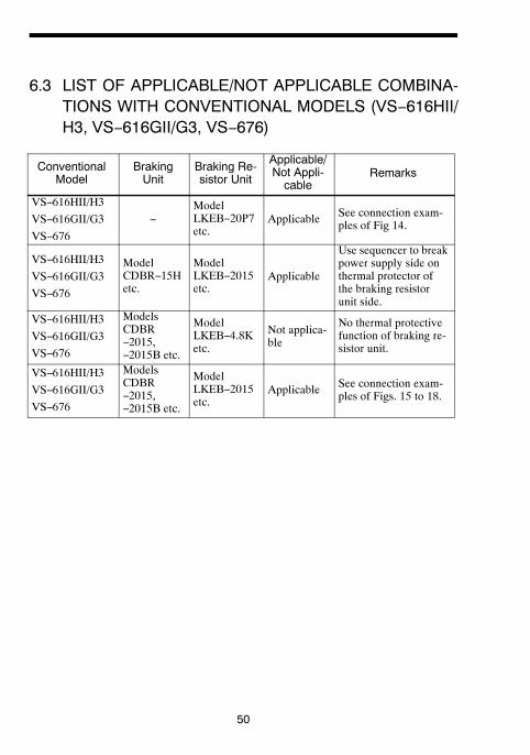
6.3 LIST OF APPLICABLE/NOT APPLICABLE COMBINA-TIONS WITH CONVENTIONAL MODELS (VS−616HII/H3, VS−616GII/G3, VS−676)
ConventionalModel
BrakingUnit
Braking Re-sistor Unit
Applicable/Not Appli-cable
Remarks
VS−616HII/H3VS−616GII/G3VS−676
−ModelLKEB−20P7etc.
Applicable See connection exam-ples of Fig 14.
VS−616HII/H3VS−616GII/G3VS−676
ModelCDBR−15Hetc.
ModelLKEB−2015etc.
Applicable
Use sequencer to breakpower supply side onthermal protector ofthe braking resistorunit side.
VS−616HII/H3VS−616GII/G3VS−676
ModelsCDBR−2015,−2015B etc.
ModelLKEB−4.8Ketc.
Not applica-ble
No thermal protectivefunction of braking re-sistor unit.
VS−616HII/H3VS−616GII/G3VS−676
ModelsCDBR−2015,−2015B etc.
ModelLKEB−2015etc.
Applicable See connection exam-ples of Figs. 15 to 18.

51
6.4 BRAKING UNIT SPECIFICATIONS
Braking Unit Model 200V to 300V 380V to 460V 500V to 575VBraking Unit ModelCDBR− 2015
B2022B
2045B
2110B
4030B
4045B
4090B
4220B
5037B
5110B
5300B
Applicable Motor OutputHP (kW)
20
(15)
30
(22)
60
(45)
150
(110)
40
(30)
60
(45)
120
(90)
300
(220)
57
(37)
150
(110)
400
(300)
Max. DischargeCurrent(A)
(peak value) *40 60 100 250 40 60 100 250 40 100 250
Outputcharac-
Rated DischargeCurrent (A) 15 20 30 80 15 18 30 80 15 30 80
charac-teristics Braking Start
Voltage 330/345/365/380V ±3V 630/660/690/730/760V ±6V 825V/ 950V ±8V
Max. HysteresisError Approx. 8V Approx. 16V
Approx.
20VPowerSupply VDC 243 (1.35×200×0.9) to 400V
peak460 (1.35×380×0.9) to 800Vpeak
607 (1.35×500×0.9)to 1000V
Protec-tive
Fin Overheat ThermostattiveFunc-tions
Power ChargeIndication Charge lamp stays ON until bus voltage drops below 50V.
Location Indoor (protected from corrosive gases and dust)
Envion- Altitude 1000m max.Envion-mentalCondi-
AmbientTemperature +14 to 104_F (−10 to +40_C) (not frozen)
Condi-tions Storage
TransportationTemperature
−4 to 140_F (−20 to +60_C)
Humidity 90%RH (non−condensing)Vibration 1G at 10 to less than 20Hz, up to 0.2G at 20 to 50 Hz
Protective Configuration Wall−mounted enclosed typeHeat Loss (W) 32 38 31 64 54 59 35 71 22 53 116
* Loading time rate can be used below 10% ED (max. 10 sec.)
6.SPECIFICATIONS

52
6.5 BRAKING RESISTOR UNIT SPECIFICATIONS
Model(LKEB−j)
Specifications
AllowableAverageDissipatedPower(W)
AllowableAverageCurrent
(Effective Value)(A)
AllowableAmbient
Temperature
20P7 70W 200Ω 30 0.3921P5 260W 100Ω 60 0.7722P2 260W 70Ω 89 1.123P7
200390W 40Ω 150 1.9
25P5 200to
520W 30Ω 220 2.727P5 to
230V 780W 20Ω 300 3.92011
230V2400W 13.6Ω 440 5.7
2015 3000W 10Ω 600 7.72018 4800W 8Ω 740 9.62022 4800W 6.8Ω 880 11.440P7 70W 750Ω 30 0.20
+14 to 122_F41P5 260W 400Ω 60 0.39 +14 to 122_F( 10 to +50_C)42P2 260W 250Ω 89 0.60 (−10 to +50_C)
43P7 390W 150Ω 150 1.045P5 520W 100Ω 220 1.547P5 380 780W 75Ω 300 2.04011
380to
4601040W 50Ω 440 3.0
4015 460V 1560W 40Ω 600 3.94018 4800W 32Ω 740 4.84022 4800W 27.2Ω 880 5.74030 6000W 20Ω 1200 7.74037 9600W 16Ω 1500 9.74045 9600W 13.6Ω 1800 11.5

53
6.6 MODELS AND CODE NOS. OF BRAKING UNIT ANDBRAKING RESISTOR UNIT
(1) Braking Unit
InverterModel Code No
Voltage HP (kW)Model Code No.
20 (15) CDBR−2015B 72600−R2150B
200 to 30 (22) CDBR−2022B 72600−R2220B200 to230V 60 (45) CDBR−2045B 72600−R2450B230V
150 (110) CDBR−2110B 72600−R21100B40 (30) CDBR−4030B 72600−R4300B
380 to 60 (45) CDBR−4045B 72600−R4450B380 to460V 120 (90) CDBR−4090B 72600−R4900B
300 (220) CDBR−4220B 72600−R42200B
500 to50 (37) CDBR−5037B 72600−R5370B
500 to575V
150 (110) CDBR−5110B 72600−R51100B575V
400 (300) CDBR−5300B 72600−R53000B
6.SPECIFICATIONS
54
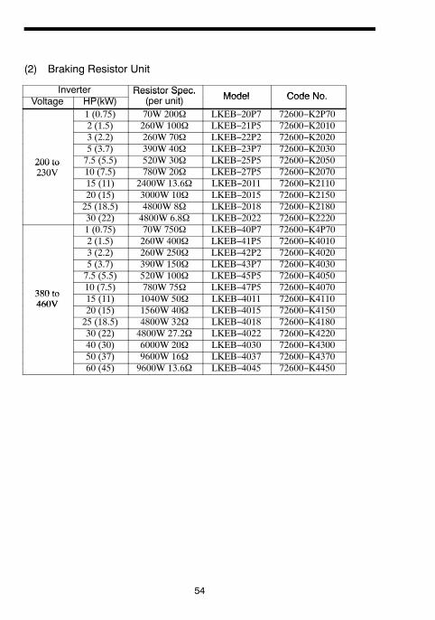
(2) Braking Resistor Unit
Inverter Resistor Spec. Model Code NoVoltage HP(kW)Resistor Spec.
(per unit) Model Code No.
1 (0.75) 70W 200Ω LKEB−20P7 72600−K2P702 (1.5) 260W 100Ω LKEB−21P5 72600−K20103 (2.2) 260W 70Ω LKEB−22P2 72600−K20205 (3.7) 390W 40Ω LKEB−23P7 72600−K2030
200 to 7.5 (5.5) 520W 30Ω LKEB−25P5 72600−K2050200 to230V 10 (7.5) 780W 20Ω LKEB−27P5 72600−K2070230V
15 (11) 2400W 13.6Ω LKEB−2011 72600−K211020 (15) 3000W 10Ω LKEB−2015 72600−K215025 (18.5) 4800W 8Ω LKEB−2018 72600−K218030 (22) 4800W 6.8Ω LKEB−2022 72600−K22201 (0.75) 70W 750Ω LKEB−40P7 72600−K4P702 (1.5) 260W 400Ω LKEB−41P5 72600−K40103 (2.2) 260W 250Ω LKEB−42P2 72600−K40205 (3.7) 390W 150Ω LKEB−43P7 72600−K40307.5 (5.5) 520W 100Ω LKEB−45P5 72600−K4050
380 to10 (7.5) 780W 75Ω LKEB−47P5 72600−K4070
380 to460V 15 (11) 1040W 50Ω LKEB−4011 72600−K4110460V
20 (15) 1560W 40Ω LKEB−4015 72600−K415025 (18.5) 4800W 32Ω LKEB−4018 72600−K418030 (22) 4800W 27.2Ω LKEB−4022 72600−K422040 (30) 6000W 20Ω LKEB−4030 72600−K430050 (37) 9600W 16Ω LKEB−4037 72600−K437060 (45) 9600W 13.6Ω LKEB−4045 72600−K4450

IRUMA BUSINESS CENTER (SOLUTION CENTER)480, Kamifujisawa, Iruma, Saitama, 358-8555, JapanPhone: 81-4-2962-5696 Fax: 81-4-2962-6138
YASKAWA ELECTRIC CORPORATIONNew Pier Takeshiba South Tower, 1-16-1, Kaigan, Minatoku, Tokyo, 105-6891, JapanPhone: 81-3-5402-4511 Fax: 81-3-5402-4580http://www.yaskawa.co.jp
YASKAWA ELECTRIC AMERICA, INC.2121 Norman Drive South, Waukegan, IL 60085, U.S.A.Phone: (800) YASKAWA (800-927-5292) or 1-847-887-7000 Fax: 1-847-887-7310http://www.yaskawa.com
YASKAWA ELÉTRICO DO BRASIL COMÉRCIO LTDA.Avenda Fagundes Filho, 620 Bairro Saude, São Paulo, SP04304-000, BrasilPhone: 55-11-3585-1100 Fax: 55-11-5581-8795http://www.yaskawa.com.br
YASKAWA ELECTRIC EUROPE GmbHHauptstraβe 185, 65760 Eschborn, GermanyPhone: 49-6196-569-300 Fax: 49-6196-569-398
YASKAWA ELECTRIC UK LTD.1 Hunt Hill Orchardton Woods, Cumbernauld, G68 9LF, United KingdomPhone: 44-1236-735000 Fax: 44-1236-458182
YASKAWA ELECTRIC KOREA CORPORATION7F, Doore Bldg. 24, Yeoido-dong, Youngdungpo-Ku, Seoul, 150-877, KoreaPhone: 82-2-784-7844 Fax: 82-2-784-8495
YASKAWA ELECTRIC (SINGAPORE) PTE. LTD.151 Lorong Chuan, #04-02A, New Tech Park, 556741, SingaporePhone: 65-6282-3003 Fax: 65-6289-3003
YASKAWA ELECTRIC (SHANGHAI) CO., LTD.No. 18 Xizang Zhong Road, Room 1702-1707, Harbour Ring Plaza, Shanghai, 200001, ChinaPhone: 86-21-5385-2200 Fax: 86-21-5385-3299
YASKAWA ELECTRIC (SHANGHAI) CO., LTD. BEIJING OFFICERoom 1011A, Tower W3 Oriental Plaza, No. 1 East Chang An Ave., Dong Cheng District, Beijing, 100738, ChinaPhone: 86-10-8518-4086 Fax: 86-10-8518-4082
YASKAWA ELECTRIC TAIWAN CORPORATION9F, 16, Nanking E. Rd., Sec. 3, Taipei, TaiwanPhone: 886-2-2502-5003 Fax: 886-2-2505-1280
英文 No.10-4(B6) インバータ製品用
In the event that the end user of this product is to be the military and said product is to be employed in any weapons systems or the manufacture thereof, the export will fall under the relevant regulations as stipulated in the Foreign Exchange and Foreign Trade Regulations. Therefore, be sure to follow all procedures and submit all relevant documentation according to any and all rules, regulations and laws that may apply.
Specifications are subject to change without notice for ongoing product modifications and improvements.
© 2005-2010 YASKAWA ELECTRIC CORPORATION. All rights reserved.
YASKAWA ELECTRIC CORPORATION
YASKAWA
Published in Japan April 2010 05-3
MANUAL NO. TOBP C720600 00C
10-3-38 -0
YASKAWA AC Drive-Option
INSTRUCTIONS
BRAKING UNIT, BRAKING RESISTOR UNIT
Related Documents