Brakes Introduction Brakes are the most important components of an automobile vehicle. The vehicle is started, accelerated and it runs on the roads But stopping of the vehicle is as essential as its starting. The mechanism which is used to slow and stop the vehicle is known as braking system Brakes are mechanical device used to stop the vehicle with in the shortest possible distance. Brake action may be defined as the force which stops any motion. When the brakes are applied on a moving vehicle the kinetic energy of the vehicles is transformed in to heat generated by the friction between the brake lining and drums. The heat generated is dissipated into the skunk air The force of Action between the- linings and the drum depends upon the coefficient of friction of the two material, form applied between the skiing surface, the roughness of the surface, and the material of which the surface: are made. Purpose of Brakes

Welcome message from author
This document is posted to help you gain knowledge. Please leave a comment to let me know what you think about it! Share it to your friends and learn new things together.
Transcript
Brakes
Introduction
Brakes are the most important components of an automobile
vehicle.
The vehicle is started, accelerated and it runs on the roads But
stopping of the vehicle is as essential as its starting.
The mechanism which is used to slow and stop the vehicle is
known as braking system
Brakes are mechanical device used to stop the vehicle with in the
shortest possible distance.
Brake action may be defined as the force which stops any motion.
When the brakes are applied on a moving vehicle the kinetic
energy of the vehicles is transformed in to heat generated by the
friction between the brake lining and drums.
The heat generated is dissipated into the skunk air
The force of Action between the- linings and the drum depends
upon the coefficient of friction of the two material, form applied
between the skiing surface, the roughness of the surface, and the
material of which the surface: are made.
Purpose of Brakes
To stop the vehicle quickly with in a shortest possible distance.
To slow down or stop the motion of a moving vehicle.
To park the vehicles
To control the speed of the vehicle.
Requirements of a good braking system
The brakes should stop the vehicle in shortest possible distance
and time.
The brakes- should work equally good (or) on bad road.
Pedal effort applied by the driver should be more.
Brakes should work equally good iii all weather .
It should have less wearing parts
should require little maintenance.
Brakes when applied should not disturb steering geometry.
When brakes are applied, the- vehicle should not pull to one side.
It should produce less noise and vibration while applying brake.
It should have less weight and reliable.
It should not be skidding while applying brake.
It should have better cooling system and less weight.
Classifications of Brakes
1. According to the application
Foot brake (or) service brake (or) running brake
Hand brake (or) parking brake (or) emergency brake
2. According to the number of wheels
2 Wheel brakes
4 Wheel brakes
3. According to location
Transmission brake
Wheel brakes
4. According to the method of braking contact
·Drum brakes
External contracting (expanding) brakes.
Internal expanding brakes.
Caliper (or) disc brakes.
Single piston caliper
Double piston caliper.
According to the mode of operation.
Mechanical brakes.
Hydraulic brakes
Electric brakes
Vacuum brakes
Vacuum assisted hydraulic brakes
Air brakes.
Air assisted hydraulic brakes.
Brake Efficiency And Stopping Distance
The maximum retarding force applied by the brakes at the
wheels, F. depends us the coefficient of friction between the road and
the lyre surface u, and the component the weight of the vehicle on the
wheel, W. i.e.. F = u W
If unity coefficient of friction is achieved, the total retarding force
produced at wheels is equal to the vehicle weight itself, which is equal
to the gravitational fo experienced by the freely falling body of mass
equal to that of vehicle. If this be the ca the vehicle experiences a
deceleration equal to the acceleration due to gravity, 'g', and the brakes
are said to be 100 percent efficient. Thus theoretical limit for brake
efficiency is 100 percent.
In actual practice, efficiency of 100 percent is rarely used for
ordinary vehicle Requirements like safety of passengers in public
vehicles and safety of the body in c; of heavy goods vehicles, reduce the
brake efficiencies to be used. Highly efficient brat giving large
deceleration might injure the passengers due to sudden stopping of the
vehicle. Similarly in the case of goods vehicles, an extra efficient
braking system would cause the load to slide forward when the brakes
are applied, tending to break the drive cabin. Moreover with very highly
efficient brakes rapid wear of lyres and brake finis takes place and there
is always a risk of losing vehicle control when brakes are applied The
brake efficiencies in general use vary from 50 % to 80 %, which enable
the vein to stop with in reasonable distance. Table gives approximate
stopping distances different vehicle velocities for various conditions of
brakes. How ever, the minims allowable limit or brake efficiency for any
vehicle is 50 % for foot brakes and 30 % for hand brakes.
The distances give in the above table. Are approximate only and
they vary with the type of the road surface and condition of lyre treads,
etc..,
However, during emergency braking, the reaction of the driver
and response tip of the brakes also play an important part. The total
stopping distance in case emergency braking may be divided into 3 parts
Distance transversed during the reaction time of the
driver.
Distance traversed during the time elapsed between the
driver pressing the brake pedal and the brake being
actually applied at the wheels.
Net stopping distance, depending upon the deceleration.
Thus the actual stopping distances will be more than the values
given in the table Rich is based upon deceleration only. These depend
upon
i) Vehicle speed.
ii) Condition of the road surface.
iii) Condition of tyre treads.
iv) Coefficient of infliction between the tyre tread and road
surface.
v) Coefficient of friction between the brake drum and the brake
lining
vi) Braking force applied by the driver.
Drum Brake
A Brake drum is connected to the wheel and also a back plate is
mounted on the as casing. In case of front axle, the back plate is bolted
to the steering knuckle. The back pie is made of pressed steel sheet and
is ribbed to increase rigidity and to provide support f the expander,
anchor and brake shoes. It also protects the drum and shoe assembly
fro mud and dust. More over, it absorbs the completer torque reaction of
the shoes due which reason it is sometimes also called 'torque plate'.
In actual practice three type of drum braking, namely: leading
trailing shoe brake, to leading shoe brake, due servo brake. In a leading
trailing shoe brake type one end of the two brake shoes are hinged on
the stationary back plate and other end is-operated by the wheel
cylinder piston. This arrangement gives to one shoes as leading shoe (A)
and to other shoe as trailing shoe (B).
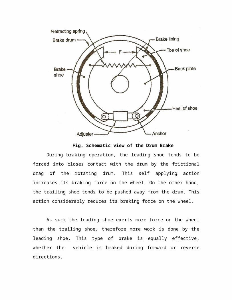
Fig. Schematic view of the Drum Brake
During braking operation, the leading shoe tends to be forced into
closes contact with the drum by the frictional drag of the rotating drum.
This self applying action increases its braking force on the wheel. On the
other hand, the trailing shoe tends to be pushed away from the drum.
This action considerably reduces its braking force on the wheel.
As suck the leading shoe exerts more force on the wheel than the
trailing shoe, therefore more work is done by the leading shoe. This type
of brake is equally effective, whether the vehicle is braked during
forward or reverse directions.

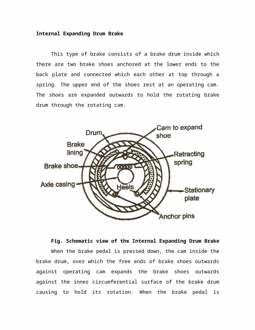
Internal Expanding Drum Brake
This type of brake consists of a brake drum inside which there are
two brake shoes anchored at the lower ends to the back plate and
connected which each other at top through a spring. The upper end of
the shoes rest at an operating cam. The shoes are expanded outwards
to hold the rotating brake drum through the rotating cam.
Fig. Schematic view of the Internal Expanding Drum Brake
When the brake pedal is pressed down, the cam inside the brake
drum, over which the free ends of brake shoes outwards against
operating cam expands the brake shoes outwards against the inner
circumferential surface of the brake drum causing to hold its rotation.
When the brake pedal is released, it comes yup through the assistance
of return spring and the brake shoe operating cam is operated in the
opposite direction. This results in the contracting of brake shoes and
release of brake.
External Contracting Brake
The main components of brakes are brake drum, an external
contracting brake band linkage, push rod, return spring, adjusting lever
and operating lever It is usually the hank brake or parking brake of the
automobile. Service brake operates on all the wheels (front and rear),
where as hand brake operates on rear wheel only. This brake may be
operates by mechanical, hydraulic, pneumatic and electrical devices. If
the service brake fails, it used as an emergency brake. As per the motor
vehicle rules the hand brake should be compulsory. The drum is fitted
with the transmission output shaft and rotates with it. The brake band
having lining of frictional material encircles the brake drum. In order to
hole the rotating brake drum, the brake band is contracted about the
drum by means of a lever and linkage.
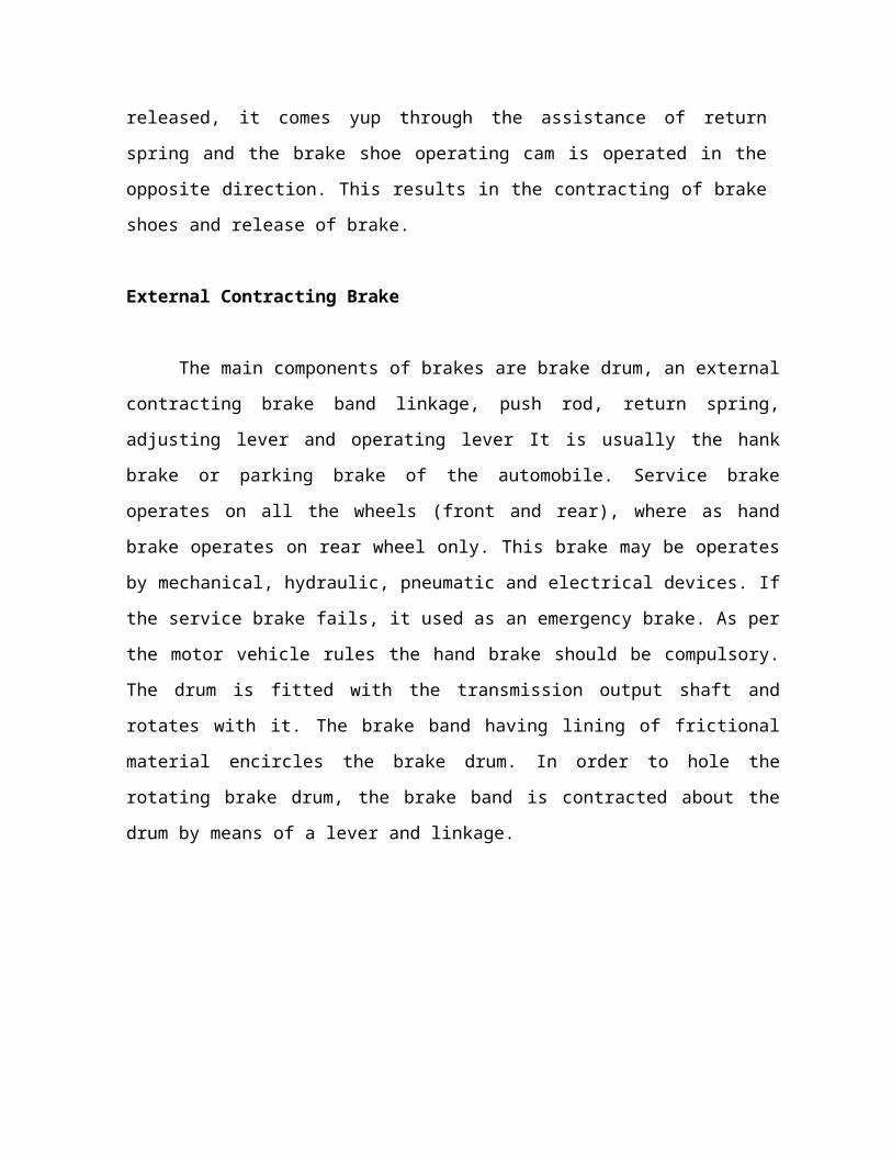
Fig. Schematic view of the External Contracting Brake
A stud is connected to the one end of the brie band through
fasteners. The stud a spring and a collar. A lever is connected to the
another end of the brake band and it is pivoted at its center to the stud.
When the lever is pressed, the spring compresses which makes the
brake band to move inwards, which helps in tightening the brake drum.
1 stops the motion of the vehicle. When the lever is released the spring
expands t original position, making the brake band to release.
Brake Shoe
Brake shoes are made of steel usually in T section which is
considered strong. They are made of cast iron or aluminum or steel.
Aluminum shoes also been tried because their good thermal
Conductivity, but their use has been very limited probably due to values
of strength and stiffness of aluminum. Pressed steel brake shoes are
selected modern vehicles.
Two types of shoes a primary shoes (leading) on the left and a
secondary shoe (trailing) on the right are provided
Primary shoe (or) leading shoe
The shoe drags along the drum and produces more *trust or
friction in the bread drum known as leading shoe or leading shoe. Its
direction is just opposite to the rotator of the drum.
Secondary shoe (or) trailing shoe
The shoes moves away from the drum while applying the brake
called Trailing shoe or secondary shoe. Its direction is the same as the
rotation of the drum.
On the brake shoe, the specially treated asbestos brake lining is
fixed with the hell of rivets now a day in some of the vehicles linings are
pasted and pressed on broke shoes with the synthetic resin adhesive.
The brake linings are usually 28 to 63mm wide and from 4 to 10mm
thick in case passenger motor vehicles.
Fig. Schematic view of the primary and Secondary Shoes
Brake drum
Brake drum are usually made of cast iron in some case brake
drum are made of steel or aluminum having inner liner of cast iron. Fins
are provided on the outer surface of the drum which helps in dissipation
of heat. The brake drum rotates with the road wheel and provides a
contacting surface for the brake shoes to come in to contact for braking
action.
Brake Lining
It is a friction material fitted on the surface of the brake shoe. At
the time of braless kinetic energy is transformed in to heat energy.
Brake liner absorbs the heat making it wear. The following types of
linings are employed with the brake shoes.
Organic lining
They are of two main varieties
Solid - woven type
. Moulded type or composition type
Solid-woven type
The woven type organic lining is woven from strands of asbestos
and threads other materials and impregnated with a rubber compounds
these innings have an avert co-efficient of friction of 0.4 and their
maximum temperature resistances is about 350 It can be reinforced and
strengthened by adding brass or zinc wires and impregnated by bonding
material
Moulded type or composition type
The molded type in made from thoroughly mixed compounds of
asbestos, filler materials and powdered resins. The compound is molded
in dies to form into shape and is placed under heat and pressure until a
hard like board is formed. It is then art and bends in to individual
segments for attachment to the brake shoes. These linings have good
wear resistance their maximum temperature resistance is about 450 C.
The average coefficient of friction is 0.4
Metallic lining
It is made of sintered metal and is composed of finely of copper or
iron, graphite Ad some amount of inorganic fillers and friction modifiers.
After thoroughly mixing the constituents a lubricating oil is added to
avoid separation of different materials. It is then made into the required
form by means of a special process. Metallic linings ore used for
extreme braking conditions as encountered in police cars, fire brigade
vehicles and sports cars under such extreme service, the fictional
qualities of the metallic linings are more constant than that of organic
linings.
Disc Brake
Disc brakes differ in construction and it can be operated in
different manner Mom the drum type brake. These brakes have a metal
disc in plate of a drum and a pair of pads in place of curved shoes.
Types of disc brakes
Spot type
Clutch type
Special types of spot type disc brakes
Fixed caliper (or) swinging
Floating caliper (or) sliding
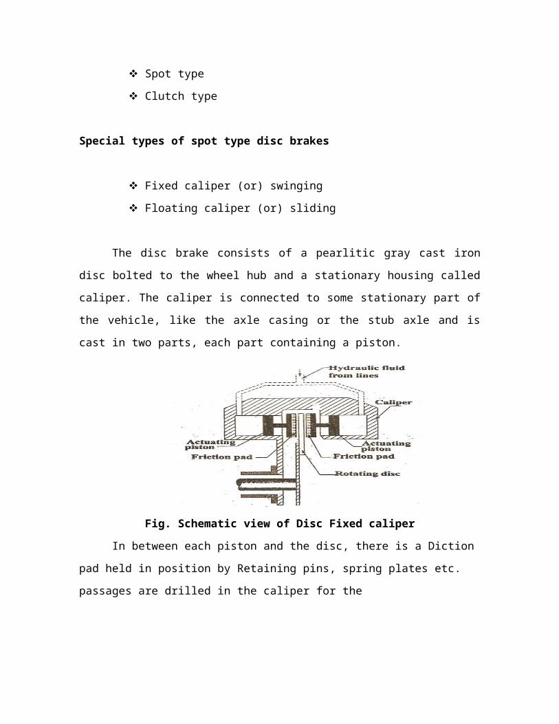
The disc brake consists of a pearlitic gray cast iron disc bolted to
the wheel hub and a stationary housing called caliper. The caliper is
connected to some stationary part of the vehicle, like the axle casing or
the stub axle and is cast in two parts, each part containing a piston.
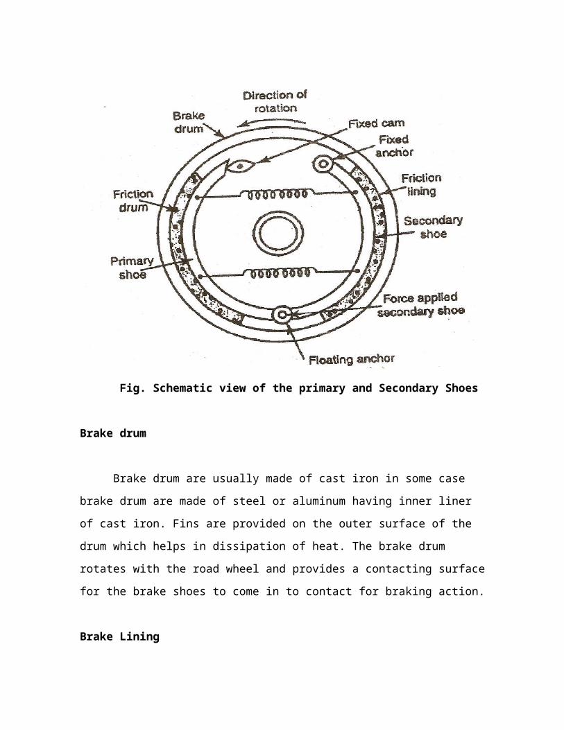
Fig. Schematic view of Disc Fixed caliper
In between each piston and the disc, there is a Diction pad held in
position by Retaining pins, spring plates etc. passages are drilled in the
caliper for the
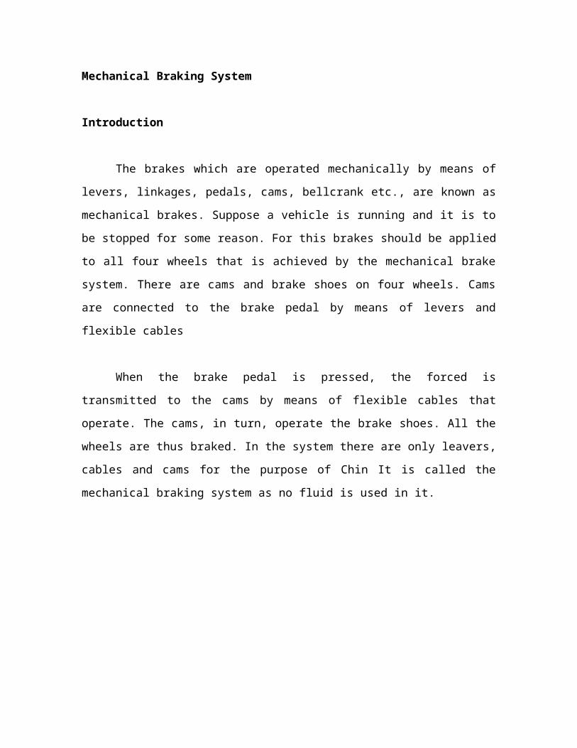
Mechanical Braking System
Introduction
The brakes which are operated mechanically by means of levers,
linkages, pedals, cams, bellcrank etc., are known as mechanical brakes.
Suppose a vehicle is running and it is to be stopped for some reason.
For this brakes should be applied to all four wheels that is achieved by
the mechanical brake system. There are cams and brake shoes on four
wheels. Cams are connected to the brake pedal by means of levers and
flexible cables
When the brake pedal is pressed, the forced is transmitted to the
cams by means of flexible cables that operate. The cams, in turn,
operate the brake shoes. All the wheels are thus braked. In the system
there are only leavers, cables and cams for the purpose of Chin It is
called the mechanical braking system as no fluid is used in it.
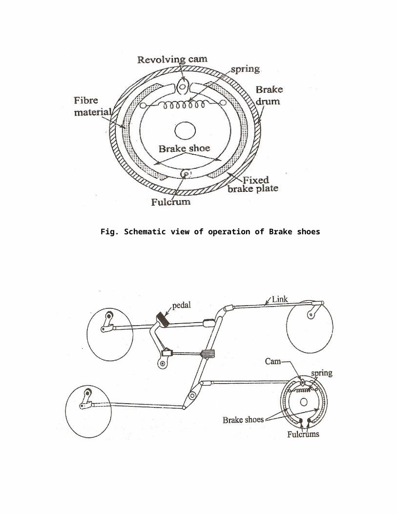
Fig. Schematic view of operation of Brake shoes
Fig. Schematic view of operation of Brake shoes
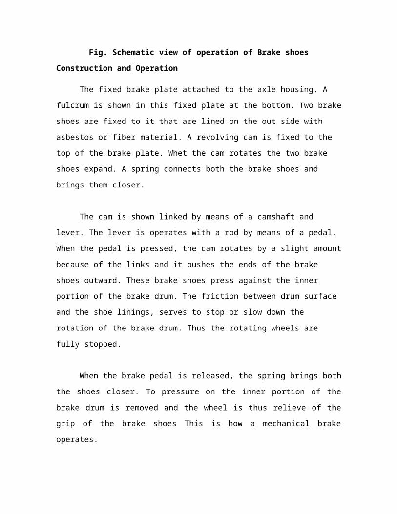
Construction and Operation
The fixed brake plate attached to the axle housing. A fulcrum is
shown in this fixed plate at the bottom. Two brake shoes are fixed to it
that are lined on the out side with asbestos or fiber material. A revolving
cam is fixed to the top of the brake plate. Whet the cam rotates the two
brake shoes expand. A spring connects both the brake shoes and brings
them closer.
The cam is shown linked by means of a camshaft and lever. The
lever is operates with a rod by means of a pedal. When the pedal is
pressed, the cam rotates by a slight amount because of the links and it
pushes the ends of the brake shoes outward. These brake shoes press
against the inner portion of the brake drum. The friction between drum
surface and the shoe linings, serves to stop or slow down the rotation of
the brake drum. Thus the rotating wheels are fully stopped.
When the brake pedal is released, the spring brings both the
shoes closer. To pressure on the inner portion of the brake drum is
removed and the wheel is thus relieve of the grip of the brake shoes
This is how a mechanical brake operates.
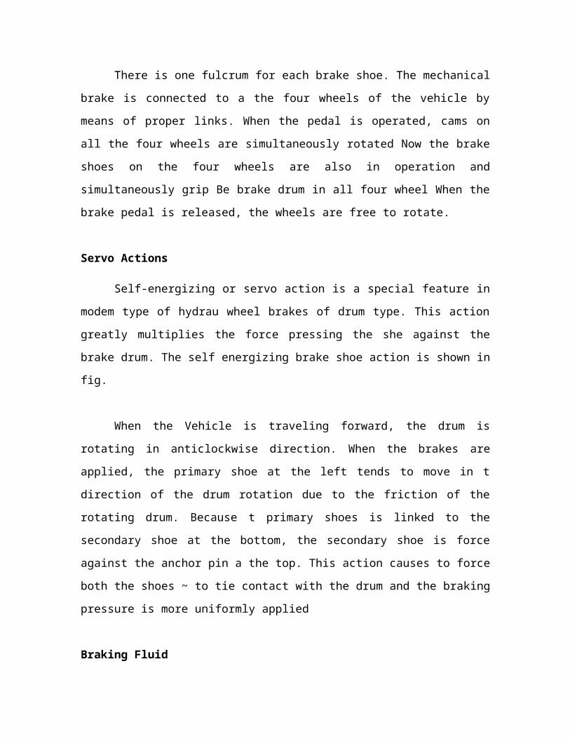
There is one fulcrum for each brake shoe. The mechanical brake is
connected to a the four wheels of the vehicle by means of proper links.
When the pedal is operated, cams on all the four wheels are
simultaneously rotated Now the brake shoes on the four wheels are also
in operation and simultaneously grip Be brake drum in all four wheel
When the brake pedal is released, the wheels are free to rotate.
Servo Actions
Self-energizing or servo action is a special feature in modem type
of hydrau wheel brakes of drum type. This action greatly multiplies the
force pressing the she against the brake drum. The self energizing brake
shoe action is shown in fig.
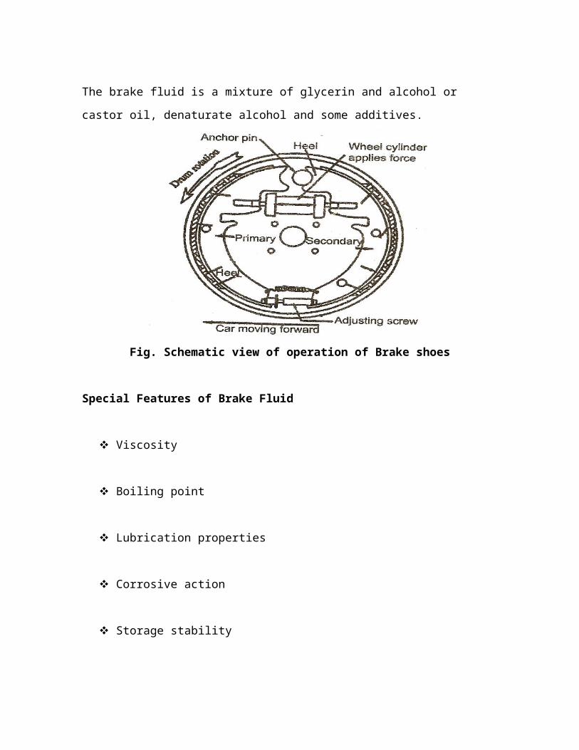
When the Vehicle is traveling forward, the drum is rotating in
anticlockwise direction. When the brakes are applied, the primary shoe
at the left tends to move in t direction of the drum rotation due to the
friction of the rotating drum. Because t primary shoes is linked to the
secondary shoe at the bottom, the secondary shoe is force against the
anchor pin a the top. This action causes to force both the shoes ~ to tie
contact with the drum and the braking pressure is more uniformly
applied
Braking Fluid
The brake fluid is a mixture of glycerin and alcohol or castor oil,
denaturate alcohol and some additives.
Fig. Schematic view of operation of Brake shoes
Special Features of Brake Fluid
Viscosity
Boiling point
Lubrication properties
Corrosive action
Storage stability
Basic Dual Air Brake System
Most air brake equipped vehicles on the road today are using a
dual air brake system. The system has been developed to accommodate
a mechanically secured parking brake that can be applied in the event
of service brake failure. It also accommodates the need for a modulated
braking system should either one of the two systems fail. It is actually
two brake systems in one, with more reservoir capacity resulting in a
much safer system. At first glance, the dual system might seem
complicated, but if you understand the basic air
brake system described so far, and if the dual system is separated into
basic functions, it becomes quite simple.
As its name suggests, the dual system is two systems or circuits in
one. There are different ways of separating the two parts of the system.
On a two–axle vehicle, one circuit operates the rear axle and the other
circuit operates the front axle.
If one circuit has a failure, the other circuit is isolated and will continue
to operate.
Dual Air Brake System
In the illustration, air is pumped by the compressor (1) to the
supply/wet reservoir (5) which is protected from over pressurization by a
safety valve (4). Pressurized air moves from the supply/wet reservoir to
the primary/dry reservoir (8) (green) and the secondary/dry reservoir
(10) (red) through one–way check valves (7). At this point, the dual
circuits start.
Air from the primary/dry reservoir is directed to the foot valve
(31). Air is also directed from the secondary/dry reservoir to the foot
valve. The foot valve is similar to the one described earlier in the basic
air brake system, but is divided into two sections. One section of this
dual foot valve controls the primary circuit and the other controls the
secondary circuit. When a brake application is made, air is drawn from
the primary reservoir through the foot valve and is passed on to the rear
brake chambers. At the same time, air is also drawn from the secondary
reservoir, passes through the foot valve and is passed on to the front
brake chambers. If there is air loss in either circuit, the other will
continue to operate independently.
Unless air is lost in both circuits, the vehicle will continue to have
braking ability. The primary and secondary circuits are equipped with
low air pressure warning devices, which are triggered by the low air
pressure indicator switch (9) and reservoir air pressure gauges (29)
located on the dash of the vehicle.
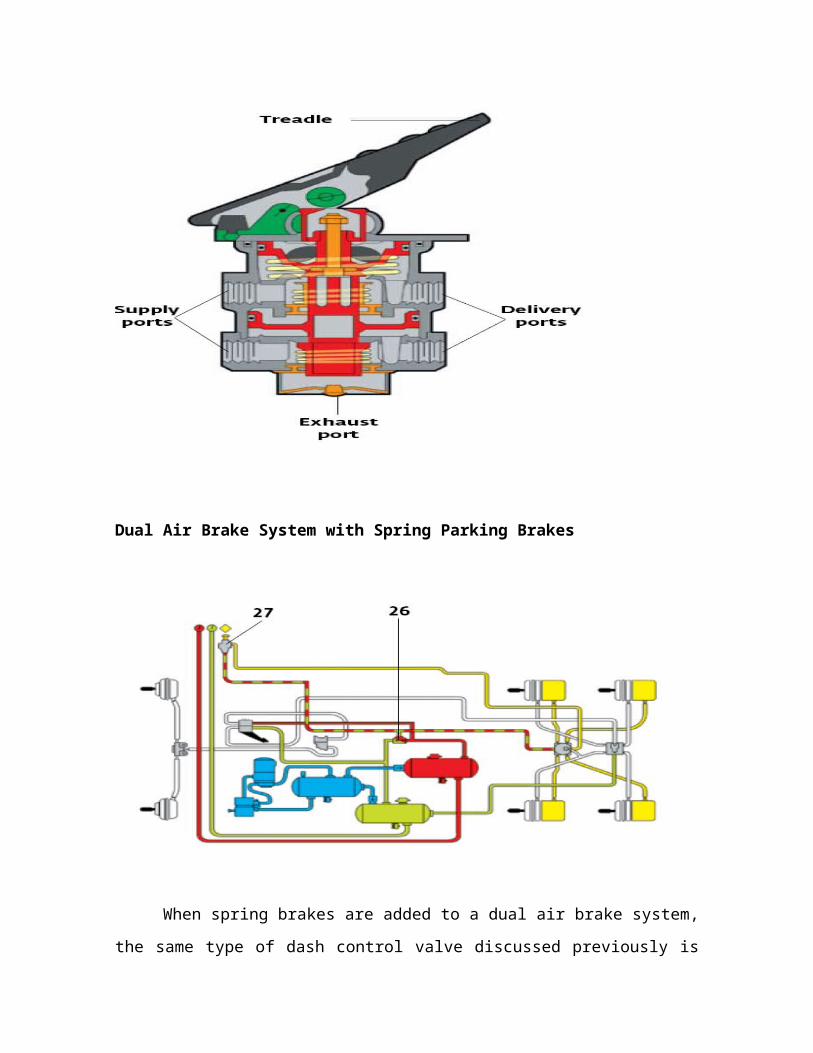
Dual–Circuit Foot Valve
Dual Air Brake System with Spring Parking Brakes
When spring brakes are added to a dual air brake system, the
same type of dash control valve discussed previously is used. Blended
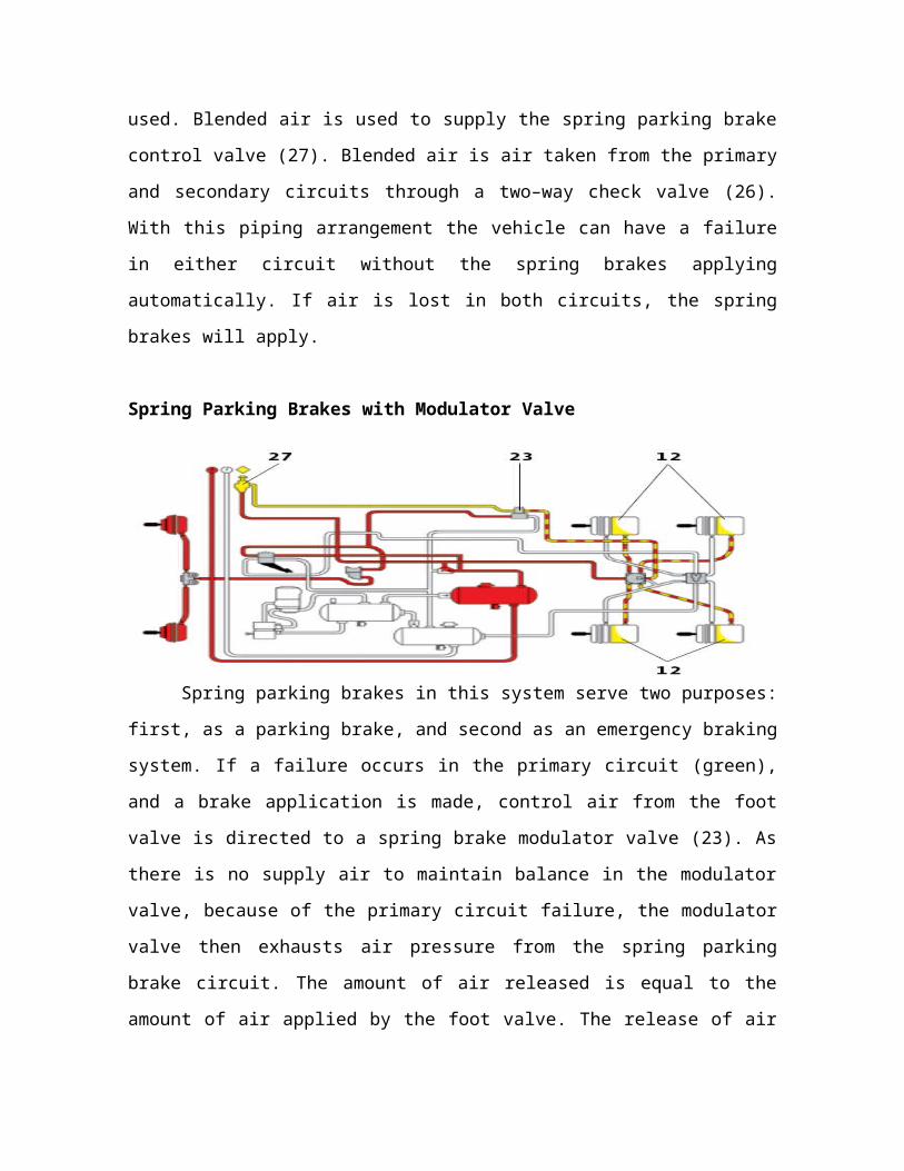
air is used to supply the spring parking brake control valve (27).
Blended air is air taken from the primary and secondary circuits through
a two–way check valve (26). With this piping arrangement the vehicle
can have a failure in either circuit without the spring brakes applying
automatically. If air is lost in both circuits, the spring brakes will apply.
Spring Parking Brakes with Modulator Valve
Spring parking brakes in this system serve two purposes: first, as
a parking brake, and second as an emergency braking system. If a
failure occurs in the primary circuit (green), and a brake application is
made, control air from the foot valve is directed to a spring brake
modulator valve (23). As there is no supply air to maintain balance in
the modulator valve, because of the primary circuit failure, the
modulator valve then exhausts air pressure from the spring parking
brake circuit. The amount of air released is equal to the amount of air
applied by the foot valve. The release of air in the spring parking brake
circuit causes the drive axle to brake using spring pressure (12).
When the brakes are released, supply air from the secondary
circuit (red) returns the spring parking brakes to an off position. Brake
applications can be repeated until all the air from the secondary circuit
is lost. However as the air pressure drops below 85 psi, the spring
parking brakes won’t return to the full off position, in fact they will start
to drag.
At approximately 35 psi, the spring parking brake control valve
(27) on the dash will exhaust the remaining air in the secondary circuit,
and the spring parking brakes are fully applied. The only way the vehicle
can be moved after all air is lost is to repair the damaged circuit and
recharge the system, or cage the spring parking brake system.
Parking Brake Mechanisms


The parking brake system is a secondary braking system used to
hold a parked car in position. They are applied independently of the
service brakes. Since there is no inertia to overcome. less braking power
is required to hold tile vehicle stationary and less force is required to
apply. The application of only two of the four brake assemblies are
required to hold tile vehicle.
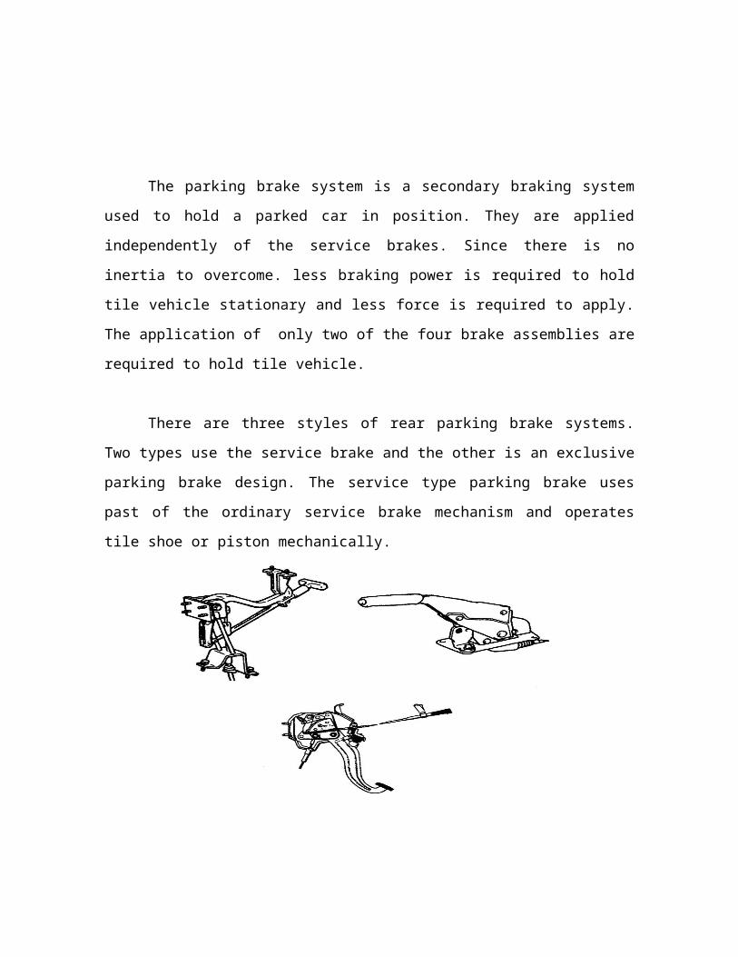
There are three styles of rear parking brake systems. Two types
use the service brake and the other is an exclusive parking brake
design. The service type parking brake uses past of the ordinary service
brake mechanism and operates tile shoe or piston mechanically.
The parking brake lever is located near the driver 's seat. Pulling
the parking brake lever by hand or pressing the pedal with the foot,
operates the brake via a cable connected to the parking brake lever of
the brake assembly.
There are a Umber of different types of parking brake levers, as
shown below. Application depends upon the denial of the driver 's seat
and tile desired operating effort.
The parking brake lever is provided with a ratchet locking
mechanism maintain tile lever at the position to which it was set. until
released. Son parking levers have an adjusting screw near tile brake
lever so tile amount of brake lever travel can be easily adjusted. Travel
is detained by the number of clicks of the retched mechanism found in
the repair manual
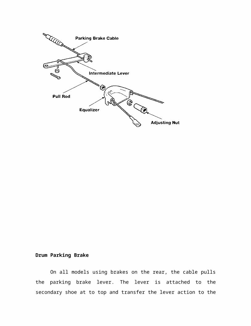
Parking Brake Linkage
The parking brake cable transmits the lever movement through a
typical series of components, as shown below, to the brake drum
subassembly. The intermediate lever multiplies the operation force to
the equalizer. The requalizer. The equalizer divides the lever operating
force to brake assemblies at both wheels. The two major parts may vary
in design however their function remains the same.
Drum Parking Brake
On all models using brakes on the rear, the cable pulls the parking
brake lever. The lever is attached to the secondary shoe at to top and
transfer the lever action to the primary shoe through the shoe strut.
When released, the brake shoe spring return the shoe to their retracted
position
Disc Parking Brakes
There are two types of rear wheel parking brake systems for
disc brakes. The first uses the brake caliper assembly to mechanically
apply pressure to the disc. The second type is an exclusive drum brake
assembly that applies pressure to an inside drum, which is an integral
part of the disc rotor.

The parking brake is built into the caliper housing and is provided
with an automatic adjusting mechanism to compensate for piston
movement as the brake pads wear.
Parking Brake Operation
When the parking brake is applied, the cable attached to the
parking brake lever rotates the crank lever counterclockwise. The crank
pin then pushes the strut to the left. The strut moves the adjusting bolt,
sleeve nut, and piston toward the left. As the strut moves to the left, it
also compresses the adjusting bolt return spring. The assembly moves
until it presses the pads against the disc rotor.
When the parking brake lever is released, the compressed Return
Spring pushes the Adjusting Bolt and Piston back to their previous
positions. As a result, the parking brake is released. During this
operation, the Clutch Spring prevents the rotation of the Sleeve Nut so
that the force of the parking brake lever is transferred to the Piston via
the Adjusting Bolt.
Principle of hydraulic brake system
Purpose
This is a better system than the mechanically operated one. The
system itself very simple and efficient. In this there are a large number
of mechanical components Wear is reduced on the brake }linings. The
liquid pressure supplies the hydraulic brakes The braking action on all
the brakes is equal...
Principle
Then the force applied to the pedal is multiplied and transmitted
to the brake shoe by a suitable transmission system based upon
Pascal's principle. It states that "pressur applied to a liquid is
transmitted equally in all directions without any losses". It natal consists
of a five cylinders filled with a liquid. The cross section of each cylinder
is cm^2. a certain force, say 10 kg. is applied at the central main
cylinder. The same force c 10 kg is applied on the other four cylinders.
These weights are supported by the li~tii~ all the cylinders. This shows
that the pressure at the central main cylinder is the same that on the
other four cylinders.
Fig. Schematic view of principle of hydraulic brake system
Construction and Operation
It mainly consists of a master cylinder and four wheel cylinders.
Every wheel cylinder contains two pistons which move outwards. The
hydraulic fluid is a mixture of glycerin ethyl alcohol, the hydraulic fluid
flows from the master cylinder to the four wheel cylinders through steel
pipe lines, union and flexible hoses. The springs are used to hold the
brake shoes on all the four wheels.
When the driver applies the brake pedal, the piston in the master
cylinder forces the liquid out of the cylinder. This liquid presses the two
pistons in the wheel cylinder outwards and these pistons push the brake
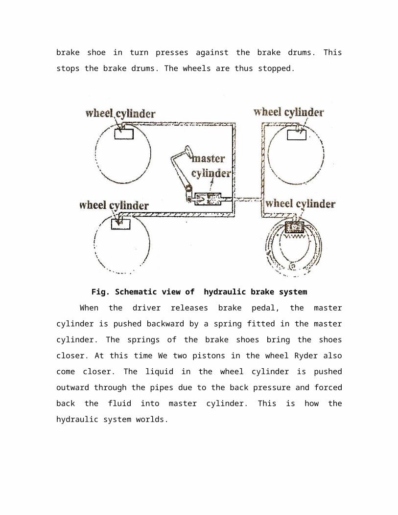
shoes outwards. The brake shoe in turn presses against the brake
drums. This stops the brake drums. The wheels are thus stopped.
Fig. Schematic view of hydraulic brake system

When the driver releases brake pedal, the master cylinder is
pushed backward by a spring fitted in the master cylinder. The springs
of the brake shoes bring the shoes closer. At this time We two pistons in
the wheel Ryder also come closer. The liquid in the wheel cylinder is
pushed outward through the pipes due to the back pressure and forced
back the fluid into master cylinder. This is how the hydraulic system
worlds.
The system is so designed that even when the brakes are in the
released position, a small pressure. of about 50 Kpa is maintained in the
pipe lines.
Advantages
Simple in construction.
Braking action on all the brakes is equal.
Increased braking effort.
Self lubrication.
Low wear rate
High mechanical advantage.
Minimum moving parts and less complicated linkage.
Friction losses are low.
Application of brake is very smooth, silent and flexible.
Disadvantages
The braking system fails if there's any leakage in the brake lines.
If the brake fluid leaks out an the brake shoes, they will be ruined.
Master Cylinder

It is the heart of the hydraulic brake system the central unit in the
hydraulic braking system is master cylinder. it produces the required
hydraulic pressure to operate the system. The pressure of the drivers
foot on brakes pedal is transmitted to the master cylinder piston
through different linkage arrangements. So, the master cylinder is
considered as the heart of the hydraulic braking system.
It serves the following objects in the system;
It produces the required hydraulic pressure to operate the
braless.
It maintains a constant volume of fluid in the system
To bleed or force air out of the brake line and wheel
cylinder, a puma is used.
Types of master cylinder
Single master cylinder for all the front and rear wheel
cylinders.
Tandem master cylinder containing separate units for Font
and rear whee cylinders.
Single Master- Cylinder
It consists of two main chambers, made of cast iron. They are
reservoir an compression chamber. The reservoir contains the fluid to
supply to the brake system. The Filler hole is covered with a plug which
contains an air vent, to keep the brake fluid always at atmospheric
pressure. The plug prevents the system from dust and watt particles.

Fig. Schematic view of Single Master Cylinder
The compression chamber contains a piston, primary and
secondary rubber cups, coil spring, outlet check valve and a rubber
seat. The compression chambers is connected with reservoir through
two holes larger port is called the intake port and the smaller port is
called the by pass port.
The pistons works inside the compression chamber and is
operated by the brake pedal through linkages. To prevent leakage there
are rubber seals on both ends of the pistons in the compression
chamber. A rubber boot covers the push rod end of the master cylinder
to keep it free from foreign matter. If check valve fails, air flows in to the
compression chamber which makes braking system to failure.
When the brake pedal in pressed down the piston inside the
cylinder pumps ort fluid in to the brake lined through the check valve as
a result, a fluid pressure is built up in the wheel cylinders. The moving
out wheel cylinder pistons expands the brake slices and the brakes are
applied.
When the brake pedal is released, the spring pressure in the
master cylinder moves Me piston to the backward. The liquid from the
four cylinders does not flow back at once. At the same time a partial
vacuum is developed in the compression chamber and unless this is
destroyed immediately, then chances of air leaking into the system.
Even a very small amount of air will render the brakes useless, since the
air being compressible.
This problem is solved by having intake port as shown, as soon as
same vacuum is formed, the atmospheric pressure in the fluid reservoir
forces the fluid through intake port and holes in the piston which
deflects the rubber cup and enters the compressions chamber,
destroying the vacuum.
But, by time this vacuum is destroyed, the fluid from the lines
comes back in reservoir by lining the fluid check valve off its seat. But-
the compression chamber is already full. The extra fluid coming from
the lines passes to the fluid reservoir through by- pass port.
When brake pedal is filly released, spring in the cylinder holds the
check vain against the rubber seat with sufficient pressure to maintains
6 to 8 lbs pressure in brake lines and wheel cylinder.
Tandem Master Cylinder
When there is any defect in the pipeline or due to any leakage of
fluid at the joint the hydraulic brake system fails. To overcome this
difficulties split system- is used Some large cars and commercial
vehicles mostly uses the split system.
The split system mainly consists of two separate cylinders and
reservoir, one for operating front brakes and the other for rear brakes.

The reservoir contains two intake ports and two bypass port. There are
tow compression springs, one between the two pistons and the other
between a piston and master cylinder cover. Under ordinal conditions
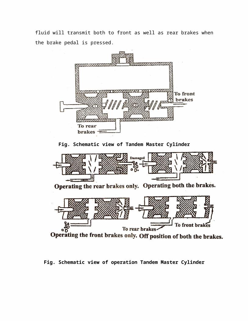
the brake fluid will transmit both to front as well as rear brakes when
the brake pedal is pressed.
Fig. Schematic view of Tandem Master Cylinder
Fig. Schematic view of operation Tandem Master Cylinder
If front brake lines are damaged piston (2) bottoms against the
end of the cylinder. After this, pressure will start building up in space
between piston (1) and piston(2) and rem brake will be applied.
Similarly when the rear brake lines are damaged, no pressure will
be built up in. space between piston(i) and piston(2). So piston (l) will
move freely till it comes up against to further push at the brake pedal,
will move both piston (l&2) together, there by applying the front brake.
The swept volume in the master cylinder chamber is the factor to
decide the braking effort. In passenger cars, generally, lager braking
effort is required at the front axle. So the larger chamber of the master
cylinder is connected to the Wont axle and the smaller chamber to the
rear axle.
In Font drive vehicles, such as maruti 800, this type of split
system with tandem master cylinder is commonly used.
Advantages
If any failure occurs in the Font wheel brakes, the brakes in
the rear wheels will be functional.
If there is any fault in the rear brakes, the brakes ~ the front
wheels will be operated.
Wheel Cylinder
The following are the Fictions of wheel cylinder;
It actuates the shoes outward to contact the brake drum.
It converts the hydraulic pressure of very low value into a
comparable mechanical force of higher value.
Construction and working
Wheel cylinder is the second important component of the
hydraulic brake system. the wheel cylinder is connected with the cast
iron housing already fitted in the individual wheels is shown in fig.,
Wheel cylinders in the brake system are meant to force the brake Hoes
against the drum. The construction is very simple. Each wheel cylinder
is provided with pistons, rubber seals (cups), seal spreaders, spring &
dust covers (boots).
The brake line from the master cylinder is attached to the port
and a bleeder screw with a cover is provided to bleed air from the
system whenever required. Wheel cylinder are mounted on the back
plate. The coil spring inside the cylinder, keeps the rubber cups in
position with the pistons. The rubber cups prevents and leakage Mom
the wheel cylinder. The dust cover protects the cylinder from foreign
substances.

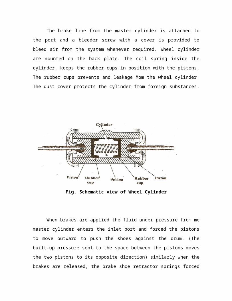
Fig. Schematic view of Wheel Cylinder
When brakes are applied the fluid under pressure from me master
cylinder enters the inlet port and forced the pistons to move outward to
push the shoes against the drum. (The built-up pressure sent to the
space between the pistons moves the two pistons to its opposite
direction) similarly when the brakes are released, the brake shoe
retractor springs forced the brake fluid out of the wheel cylinder by
pushing the piston inward.
Bleeding Hydraulic System
In hydraulic brakes, care must be taken that not even small
quantities of air enters into the braking stem. Coke air being
compressible, it gets compressed when Me brisk pedal is Pressed. The
result is that fluid pressure is not transmitted to the brakes which, a
consequence. Are not actuated.
The procedure of driving air out of the braking system is called
bleeding. A specie bleeding valve is provided for this purpose on the
shoe expander or disk caliper. For bleeding, the master cylinder is

topped up completely wig the brake fluid and pipe is connected to the
bleeding valve nipple as shown in the figure.
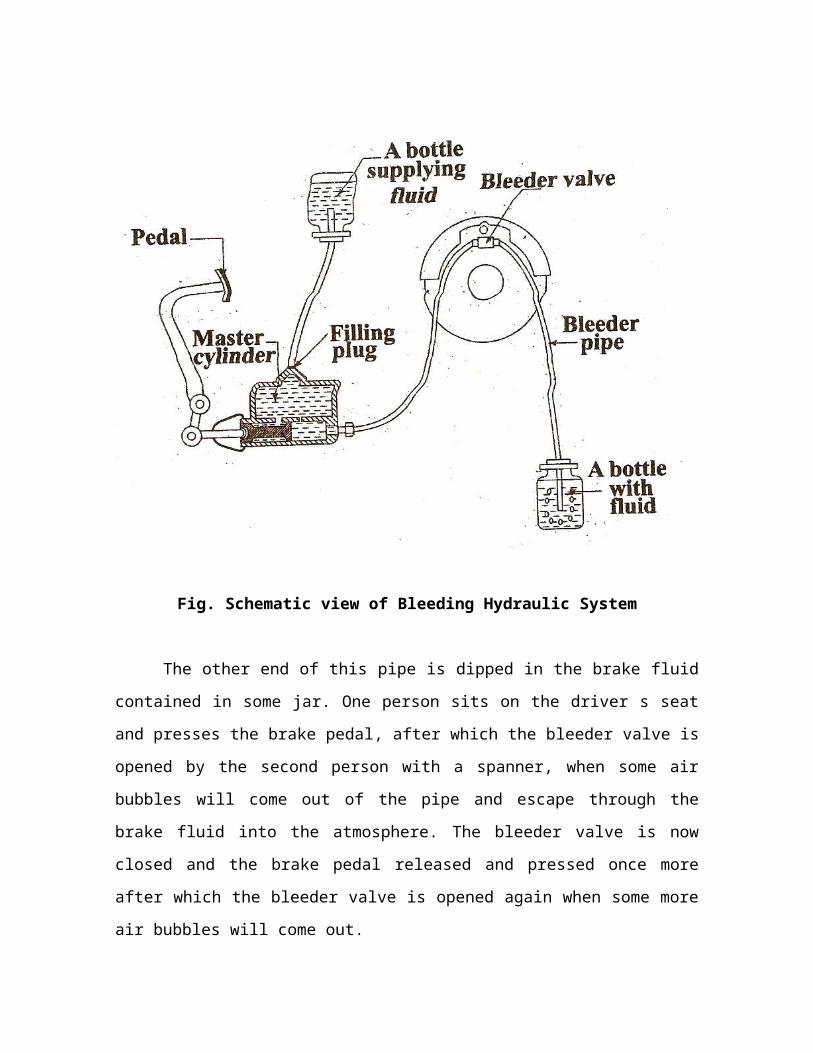
Fig. Schematic view of Bleeding Hydraulic System
The other end of this pipe is dipped in the brake fluid contained in
some jar. One person sits on the driver s seat and presses the brake
pedal, after which the bleeder valve is opened by the second person
with a spanner, when some air bubbles will come out of the pipe and
escape through the brake fluid into the atmosphere. The bleeder valve
is now closed and the brake pedal released and pressed once more after
which the bleeder valve is opened again when some more air bubbles
will come out.

This procedure is repeated till on pressing the brake pedal, on
more air bubbled are noted when with the pedal in the pressed position
the bleeder valve is closed The reservoir is then topped up with Me
fresh fluid. This procedure is then repeated for all wheels. this process is
also known as manual bleeding.
The position of the brake valve is such that the atmospheric air
enters through it and then fills up the portion to the led of the
diaphragm. There are a few holes to the right of the diaphragm that
connect the air chamber to the Atmosphere. At this stage both sides of
the diaphragm are filled up with the atmospheric air. The brake cam is
linked to the push rod of the diaphragm. The brake shoes are not
expanded in this position.
In fig the position of the brake valve has been brought to the left.
Here the compressed air is pressing the diaphragm from the left. Thus,
there is only atmospheric pressure to the right of the diaphragm. The
pressure of the compressed air is higher than the atmospheric pressure.
The diaphragm is therefore, pushed to the right. This is linked to the
push rod that operates the brake cam. When the cam rotates, the brake
shoes expand. The brake is thus applied.
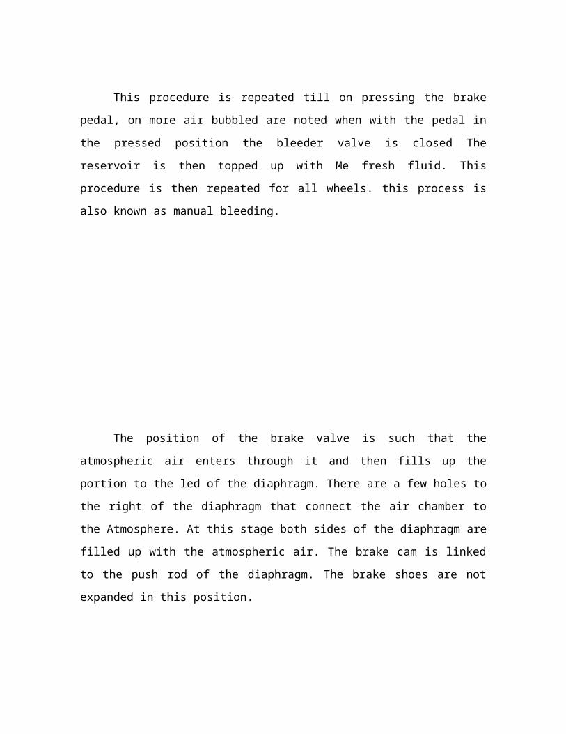
Construction and working
The function of the air compressor is to develop air to a higher
pressure. This pressure should be sufficient to operate the brake
system. Tlie compressor pumps out the air to the storage tank. This
goes on till the tank is filled up with the required amount of air. When no
figurer air is required, the unloaded valve is operated to relieve the load
on the compressor.
This air passes through the unloaded to the reservoir. The
reservoir keeps the air at maximum pressure required for operating the
brake system. If the pressure in the reservoir can get damaged.
Therefore, a safety valve is provided in the reservoir. It released the air
pressure after it goes beyond a certain limit. There is also a drain pug
which is removed when the reservoir is to be cleaned. Reservoirs
maintain 900 kpa of pressure. Pressure drops 700 kpa the unloaded
valve again cues in the compressor to raise system pressure. To reduce
the pressure at below 400 kpa warrining or buzzer is sounded.
The air from the reservoir passes through an air filter. The air filter
removes the fine particles of dust present in the air. This pure air now
goes to the brake valve. Brake pedel is fitted to the top portion of the
brake valve.
When the brake pedel is pressed, the brake valve is operated, the
compressed air flows in to the brake chambers of each of the four
wheels. that means brake valve having 4 outlets, first outlet is to be
connected at front wheels, second outlet is to be connected at rear
wheels, third outlet is to be operate stop light switch, fourth outlet is a
return air passage. The diaphragms of the four brake chambers are thus
operated. This is how the brakes are applied in the air brake system. All
the front and rear wheels are connected to the air brake system. The
hand brake is used mechanically for applying brakes only to the rear
wheels.
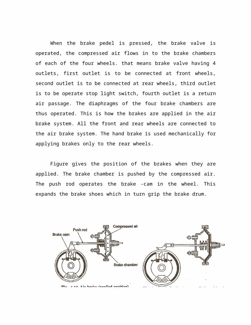
Figure gives the position of the brakes when they are applied. The
brake chamber is pushed by the compressed air. The push rod operates
the brake -cam in the wheel. This expands the brake shoes which in turn
grip the brake drum.
Figure gives the position of the heralds when they are not applied.
Hence the atmospheric air acting Mom the left has pushed the
diaphragm to the extreme right end.
Air Assisted Hydraulic Brakes
Introduction
In the present days of increasing road speeds, power brakes bring
a welcome addition to the safety factor in modern automobiles .servo
assisted power brakes provide instant stopping with minimum pressure
on the brake pedal .this result in less pedal effort .the driver fatigue is
also reduced. Compressed air is used for the driver faigue is alsc
reduced compressed air is used for actuation. When the driver actuates
the brake, the compressed air then supplies mast of the effort required
for braking.
Construction and working
In vacuum assisted brake, vacuum was talon for pushing the push
rod of the maste cylinder. In air assisted hydraulic brake system instead
of vacuum, air is used fo application of brakes. The brake pedal link and
push rod of master cylinder is so designed and linked that in the event
of failure of air pressure, brakes can be applied but once again more
foot pressure will be required. It is also designed that to stop the vehicle
in air serve brake approximately half foot pressure is required in
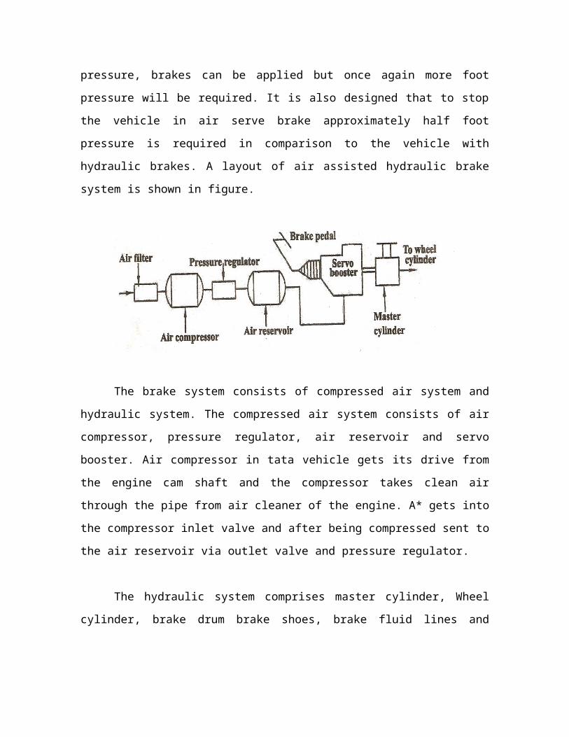
comparison to the vehicle with hydraulic brakes. A layout of air assisted
hydraulic brake system is shown in figure.
The brake system consists of compressed air system and
hydraulic system. The compressed air system consists of air
compressor, pressure regulator, air reservoir and servo booster. Air
compressor in tata vehicle gets its drive from the engine cam shaft and
the compressor takes clean air through the pipe from air cleaner of the
engine. A* gets into the compressor inlet valve and after being
compressed sent to the air reservoir via outlet valve and pressure
regulator.
The hydraulic system comprises master cylinder, Wheel cylinder,
brake drum brake shoes, brake fluid lines and hoses. There is a check
valve at the end of the master cylinder to control the flow of brake oil
The servo booster is mainly made up of 3 parts such as (i) air
control valve (ii piston and cylinder and (iii) master cylinder. The brake
booster used in Tata vehicles. In this figure the rod A linked to the brake
pedal.
The other end of the rod A is linked with lever B. the upper
portions of lever B is linked with piston rod D and lower part of lever B
linked with pressure valve P. the piston rod D is connected to the master
cylinder piston and the piston kept in oppositions by spring C.
When the brake pedal is pressed, the rod A moves forward. This
movement of the brake pedal rod makes the valve rod to move which in
turn makes the air control valve opens which allows the high pressure
air to get into the cylinder behind the piston. Due to this high pressure,
piston moves forwared pushing the master cylinder rod. Due to this the
brake oil under pressure from the master cylinder goes to the wheel
cylinders and brake are applied.

When the brake pedal is released, inlet valve is closed alla out let
valve is opened The entire pressure admitted into the servo cylinder is
released to atmosphere and th^t spring moves the servo piston
backward. The master cylinder piston return to its origins position due
to the return spring pressure. The fluid pressure in the entire system
drops to its original low value and the return spring pull the brake shoes
away Tom the brake drums this causes the wheel cylinder piston also to
come back to their orginal inward positions. Thus brake is released.
Brake Show Adjustment Mechanism
There are various methods to adjust the brake shop, The most
common types ens important ones are the
Micram adjuster
Screw adjuster.
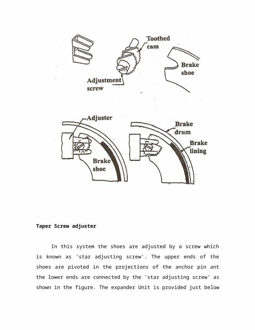
Micram type adjustment of brake shoes
This system is very effective and simple in construction as shown
in figure. The mechanism consists two scroll members provided one for
each brake shoe to adjust them. each scroll member is mounted
between the brake shoe and the member M is fixed to the actuating
plunger. The brake shoe bears on the pin of the scroll member and the
scrol] member itself bears on a locking tooth or ridge of the member M.
The scroll member is provided with toothed cam and can be
turned by a screw driver when there is desire to the shoe adjustment.
The position of the adjustment is locked by securing the tooth of the
cam in the ridge of the member M. this system is generally used in
hydraulic brakes.
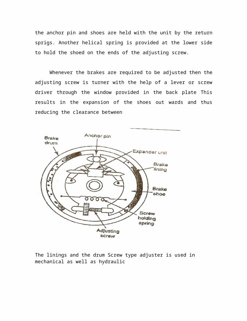
Taper Screw adjuster
In this system the shoes are adjusted by a screw which is known
as 'star adjusting screw'. The upper ends of the shoes are pivoted in the
projections of the anchor pin ant the lower ends are connected by the
'star adjusting screw' as shown in the figure. The expander Unit is
provided just below the anchor pin and shoes are held with the unit by
the return sprigs. Another helical spring is provided at the lower side to
hold the shoed on the ends of the adjusting screw.
Whenever the brakes are required to be adjusted then the
adjusting screw is turner with the help of a lever or screw driver through
the window provided in the back plate This results in the expansion of
the shoes out wards and thus reducing the clearance between
The linings and the drum Screw type adjuster is used in mechanical as well as hydraulic
Anti-Lock Braking System
Introduction
Stopping a car in a hurry on a slippery road can be very
challenging. Anti-lock braking systems (ABS) take a lot of the challenge
out of this sometimes nerve-wracking event. In fact, on slippery
surfaces, even professional drivers can't stop as quickly without ABS as
an average driver can with ABS
In this system, the last in a six-part series on brakes, we'll learn all
about anti-lock braking systems -- why you need them, what's in them,
how they work, some of the common types and some associated
problems
The ABS System
The theory behind anti-lock brakes is simple. A skidding wheel
(where the tire contact patch is sliding relative to the road) has less
traction than a non-skidding wheel. If you have been stuck on ice, you
know that if your wheels are spinning you have no traction. This is
because the contact patch is sliding relative to the ice
By keeping the wheels from skidding while you slow down, anti-
lock brakes benefit you in two ways: You'll stop faster, and you'll be able
to steer while you stop.
There are four main components to an ABS system:
Speed sensors
Pump
Valves
Controller
Speed Sensors
The anti-lock braking system needs some way of knowing when a
wheel is about to lock up. The speed sensors, which are located at each
wheel, or in some cases in the differential, provide this information.
Valves
There is a valve in the brake line of each brake controlled by the
ABS. On some systems, the valve has three positions:
In position one, the valve is open; pressure from the master
cylinder is passed right through to the brake.
In position two, the valve blocks the line, isolating that brake from
the master cylinder. This prevents the pressure from rising further
should the driver push the brake pedal harder.
In position three, the valve releases some of the pressure from the
brake.
Pump
Since the valve is able to release pressure from the brakes, there
has to be some way to put that pressure back. That is what the pump
does; when a valve reduces the pressure in a line, the pump is there to
get the pressure back up.
Controller

The controller is a computer in the car. It watches the speed
sensors and controls the valves.
ABS at Work
There are many different variations and control algorithms for ABS
systems. We will discuss how one of the simpler systems works.
The controller monitors the speed sensors at all times. It is looking
for decelerations in the wheel that are out of the ordinary. Right before
a wheel locks up, it will experience a rapid deceleration. If left
unchecked, the wheel would stop much more quickly than any car
could. It might take a car five seconds to stop from 60 mph (96.6 kph)
under ideal conditions, but a wheel that locks up could stop spinning in
less than a second.
The ABS controller knows that such a rapid deceleration is
impossible, so it reduces the pressure to that brake until it sees an
acceleration, then it increases the pressure until it sees the deceleration
again. It can do this very quickly, before the tire can actually
significantly change speed. The result is that the tire slows down at the
same rate as the car, with the brakes keeping the tires very near the
point at which they will start to lock up. This gives the system maximum
braking power.

When the ABS system is in operation you will feel a pulsing in the
brake pedal; this comes from the rapid opening and closing of the
valves. Some ABS systems can cycle up to 15 times per second.
Anti-Lock Brake Types
Anti-lock braking systems use different schemes depending on the
type of brakes in use. We will refer to them by the number of channels --
that is, how many valves that are individually controlled -- and the
number of speed sensors.
Four-channel, four-sensor ABS
This is the best scheme. There is a speed sensor on all four wheels
and a separate valve for all four wheels. With this setup, the controller
monitors each wheel individually to make sure it is achieving maximum
braking force.
Three-channel, three-sensor ABS
This scheme, commonly found on pickup trucks with four-wheel
ABS, has a speed sensor and a valve for each of the front wheels, with
one valve and one sensor for both rear wheels. The speed sensor for the
rear wheels is located in the rear axle.
This system provides individual control of the front wheels, so
they can both achieve maximum braking force. The rear wheels,
however, are monitored together; they both have to start to lock up
before the ABS will activate on the rear. With this system, it is possible
that one of the rear wheels will lock during a stop, reducing brake
effectiveness.
One-channel, one-sensor ABS
This system is commonly found on pickup trucks with rear-wheel
ABS. It has one valve, which controls both rear wheels, and one speed
sensor, located in the rear axle.
This system operates the same as the rear end of a three-channel
system. The rear wheels are monitored together and they both have to
start to lock up before the ABS kicks in. In this system it is also possible
that one of the rear wheels will lock, reducing brake effectiveness.
This system is easy to identify. Usually there will be one brake line
going through a T-fitting to both rear wheels. You can locate the speed
sensor by looking for an electrical connection near the differential on
the rear-axle housing.
Retarded Engine Brakes
A retarder is a device used to augment or replace some of the
functions of primary friction-based braking systems of heavy vehicles.
Friction-based braking systems are susceptible to 'fade' when
used extensively, and this can become dangerous if the braking
performance drops below that required to stop a vehicle for instance if a
lorry or coach is descending a long incline. For this reason, such heavy
vehicles are frequently fitted with a supplementary system that is not
friction-based.
Retarders are not restricted to road vehicles, but may also be used also
in railway systems.
The British prototype Advanced Passenger Train used hydraulic
retarders to allow the high-speed train to stop in the same distance as
standard lower speed trains, as a purely friction-based system was not
viable.
Retarders serve to slow vehicles down, or maintain a steady
speed on inclines. They are usually not capable of bringing vehicles to a
standstill, as their effectiveness diminishes at low speeds. They are
usually used to slow vehicles down, with the final braking being carried
out by a friction brake. As the friction brake does not then need to be
used so much, particularly at higher speeds, the service lifetime of
friction brakes is enhanced.
The Engine Brake
Petrol-engined vehicles
Most petrol-driven car drivers are familiar with the use of so-called
engine braking to descend inclines: put the car in low gear and do not
use the accelerator. The retardation effect is not caused by friction in
the engine, but by the fact that with the throttle closed, air cannot enter
the cylinder on the intake stroke of the pistons. Essentially, a partial
vacuum is being created at each intake stroke, and the energy required
to create this partial vacuum comes from the transmission, hence
retarding the motion of the vehicle.
Diesel-engined vehicles
Diesel-engined vehicles do not have a throttle, as they regulate
power output purely by the volume of fuel sprayed into the cylinders, so
the engine braking generated by creating partial vacua at each intake
stroke in petrol engines does not apply to diesel engined vehicles -- they
are quite 'free-running'. However Clessie M. Cummins, founder of
Cummins Engine Company, realised that by opening the cylinder
exhaust valves when the piston reached top dead centre, rather than at
the end of the power stroke the accumulated compressed air in the
cylinder could be vented before it could act as a 'spring' to drive the
piston back down again. By doing this, the engine acts as an air
compressor, with the energy used to compress the air coming from the
transmission, hence retarding the vehicle. The amount of power
extracted from the transmission can be up to 90% of the rated power of
the engine for certain engines.
This type of retarder is known to North American heavy vehicle
drivers as a Jake brake, named after such a system produced by the
Jacobs Manufacturing Company. A disadvantage of this system is that it
is very noisy in operation, such that some stretches of road ban its use.
The exhaust brake
The exhaust brake is simpler in operation than an engine brake.
Essentially, the exhaust pipe of the vehicle is restricted by a valve. This
raises the pressure in the exhaust system, forcing the engine to work
harder on the exhaust stroke of its cylinders, so again the engine is
acting as an air compressor, with the power required to compress the
air being taking from the transmission, and therefore retarding the
vehicle. A disadvantage of this system is that the exhaust pipe has to be
engineered to accommodate the high pressures generated by this
method of retardation.
The hydraulic retarder
Hydraulic retarders use the viscous drag forces between dynamic
and static vanes in a fluid-filled chamber to deliver their retardation.
There are several different types which can use standard transmission
fluid (oil), separate oil, or water.
A simple retarder would use vanes attached to a transmission
driveshaft between the clutch and roadwheels. They can also be driven
separately via gears off a driveshaft. The vanes would be enclosed in a
static chamber with small clearences to the chamber's walls (which will
also be vaned), as in an automatic transmission. When retardation is
required, fluid (oil or water) is pumped into the chamber, and the
viscous drag induced will slow down the vehicle. The working fluid will
heat up, and will usually be circulated through a cooling system. The
degree of retardation can be varied by adjusting the fill level of the
chamber.
Hydraulic retarders are extremely quiet in operation compared to
engine brakes.
The Eddy retarder
The electric retarder uses electromagnetic induction to provide a
retardation force. An electric retardation unit can be placed on an axle,
transmission, or driveline and consists of a rotor attached to the axle,
transmission, or driveline and a stator securely attached to the vehicle
chassis. There are no contact surfaces between the rotor and stator,
and no working fluid. When retardation is required, the electrical
windings in the stator are powered up from the vehicle battery,
producing magnetic fields alternating in polarity for the rotor to move in.
This induces eddy currents in the rotor, which slows down the rotor, and
hence the axle, transmission or driveshaft to which it is attached. The
rotor is engineered to provide its own air-cooling, so no load is placed on

the vehicles cooling system, and the operation of the system is
extremely quiet.
Section Summary Questions
1. What is the basic principle of the dual air brake system?
2. What valve is used to protect the primary circuit from the
secondary circuit?
3. In a dual air brake system, will the vehicle continue to have
braking ability if one
circuit fails?
4. Is there a difference between the foot valve used in a basic air
brake system and the foot valve used in the dual air brake system?
5. Name two functions of the spring parking brakes in a dual air
brake system.
6. Describe the functions of the spring brake modulator valve.
7. If the trailer breaks away from the tractor
on a dual air brake system, what applies
the brakes on the trailer?
8. What is blended air?
9. Can a trailer with a basic air brake system be towed by a
tractor with a dual air brake system?
Related Documents