Journal of Constructional Steel Research 65 (2009) 452–465 www.elsevier.com/locate/jcsr Bracing systems for seismic retrofitting of steel frames L. Di Sarno a,* , A.S. Elnashai b a Department of Engineering, University of Sannio, Benevento, Italy b Department of Civil and Environmental Engineering, University of Illinois at Urbana-Champaign, USA Received 14 August 2007; accepted 15 February 2008 Abstract The present study assesses the seismic performance of steel moment resisting frames (MRFs) retrofitted with different bracing systems. Three structural configurations were utilized: special concentrically braces (SCBFs), buckling-restrained braces (BRBFs) and mega-braces (MBFs). A 9-storey steel perimeter MRF was designed with lateral stiffness insufficient to satisfy code drift limitations in zones with high seismic hazard. The frame was then retrofitted with SCBFs, BRBFs and MBFs. Inelastic time-history analyses were carried out to assess the structural performance under earthquake ground motions. Local (member rotations) and global (interstorey and roof drifts) deformations were employed to compare the inelastic response of the retrofitted frames. It is shown that MBFs are the most cost-effective bracing systems. Maximum storey drifts of MBFs are 70% lower than MRFs and about 50% lower than SCBFs. The lateral drift reductions are, however, function of the characteristics of earthquake ground motions, especially frequency content. Configurations with buckling-restrained mega-braces possess seismic performance marginally superior to MBFs despite their greater weight. The amount of steel for structural elements and their connections in configurations with mega-braces is 20% lower than in SCBFs. This reduces the cost of construction and renders MBFs attractive for seismic retrofitting applications. c 2008 Elsevier Ltd. All rights reserved. Keywords: Bracing; Buckling restrained braces; Steel frames; Concentrically braced frames; Moment resisting frames; Ductility; Seismic retrofitting; Performance assessment; Time history analyses 1. Introduction Damage experienced during past earthquakes worldwide demonstrates that steel multi-storey building structures gener- ally exhibit adequate seismic response (e.g. [1]). This is due to the favourable mass-to-stiffness ratio of base metal and the enhanced energy absorption of structural ductile systems em- ployed. Nonetheless, relatively recent earthquakes, e.g. those in the 1994 Northridge (California), 1995 Kobe (Japan) and 1999 Chi-Chi (Taiwan), have shown that poor detailing of connec- tions (e.g. beam-to-column, brace-to-beam, brace-to-column and column-to-base) and buckling of diagonal braces can un- dermine the seismic performance of the structure as whole (see, for example, [2–6]). Fig. 1 shows the distribution of damage level and the damage to structural members and connections with respect to structural type as surveyed in the aftermath of the 1995 Hyogoken-Nanbu (Kobe) earthquake [7]. Damaged * Corresponding address: Department of Engineering, University of Sannio, Piazza Roma, 21, 82100Benevento, Italy. Tel.: +39 0824305566; fax: +39 (0)824 325246. E-mail address: [email protected] (L. Di Sarno). buildings are classified as having unbraced (UFs) or braced (BFs) frames. Thus, considering the two principal framing ori- entations of a building, the surveyed structures include the following designations: UF-UF (unbraced frames in two hori- zontal directions), UB-BF (unbraced frames in one horizontal direction and braced frames in the other direction), and BF- BF (braced frames in both horizontal directions). Beams con- sisted almost exclusively of wide-flange sections, either rolled or built-up. For columns, wide-flange (H) sections were used most extensively; square-tube (S) sections were also utilized in some structural systems. Considering the 988 damaged steel buildings, 432 (43.7%) are UF-UF, 134 (13.6%) are UF-BF and 34 (3.4%) are BF-BF, with 388 (39.3%) having uniden- tified framing systems. These statistics indicate that the ma- jority of damaged buildings had unbraced moment resisting frames (MRFs) as earthquake-resistant system. Fig. 1 also dis- plays the location of damage, namely columns, beams, beam- to-column connections, braces and column bases, as a function of frame type. Major observations from the collected data are as follows [8]: (i) columns in UFs suffered the most damage relative to other frame elements (in terms of the number of 0143-974X/$ - see front matter c 2008 Elsevier Ltd. All rights reserved. doi:10.1016/j.jcsr.2008.02.013

Welcome message from author
This document is posted to help you gain knowledge. Please leave a comment to let me know what you think about it! Share it to your friends and learn new things together.
Transcript
Journal of Constructional Steel Research 65 (2009) 452–465www.elsevier.com/locate/jcsr
Bracing systems for seismic retrofitting of steel frames
L. Di Sarnoa,∗, A.S. Elnashaib
a Department of Engineering, University of Sannio, Benevento, Italyb Department of Civil and Environmental Engineering, University of Illinois at Urbana-Champaign, USA
Received 14 August 2007; accepted 15 February 2008
Abstract
The present study assesses the seismic performance of steel moment resisting frames (MRFs) retrofitted with different bracing systems. Threestructural configurations were utilized: special concentrically braces (SCBFs), buckling-restrained braces (BRBFs) and mega-braces (MBFs). A9-storey steel perimeter MRF was designed with lateral stiffness insufficient to satisfy code drift limitations in zones with high seismic hazard. Theframe was then retrofitted with SCBFs, BRBFs and MBFs. Inelastic time-history analyses were carried out to assess the structural performanceunder earthquake ground motions. Local (member rotations) and global (interstorey and roof drifts) deformations were employed to comparethe inelastic response of the retrofitted frames. It is shown that MBFs are the most cost-effective bracing systems. Maximum storey drifts ofMBFs are 70% lower than MRFs and about 50% lower than SCBFs. The lateral drift reductions are, however, function of the characteristicsof earthquake ground motions, especially frequency content. Configurations with buckling-restrained mega-braces possess seismic performancemarginally superior to MBFs despite their greater weight. The amount of steel for structural elements and their connections in configurations withmega-braces is 20% lower than in SCBFs. This reduces the cost of construction and renders MBFs attractive for seismic retrofitting applications.c© 2008 Elsevier Ltd. All rights reserved.
Keywords: Bracing; Buckling restrained braces; Steel frames; Concentrically braced frames; Moment resisting frames; Ductility; Seismic retrofitting; Performanceassessment; Time history analyses
1. Introduction
Damage experienced during past earthquakes worldwidedemonstrates that steel multi-storey building structures gener-ally exhibit adequate seismic response (e.g. [1]). This is dueto the favourable mass-to-stiffness ratio of base metal and theenhanced energy absorption of structural ductile systems em-ployed. Nonetheless, relatively recent earthquakes, e.g. those inthe 1994 Northridge (California), 1995 Kobe (Japan) and 1999Chi-Chi (Taiwan), have shown that poor detailing of connec-tions (e.g. beam-to-column, brace-to-beam, brace-to-columnand column-to-base) and buckling of diagonal braces can un-dermine the seismic performance of the structure as whole (see,for example, [2–6]). Fig. 1 shows the distribution of damagelevel and the damage to structural members and connectionswith respect to structural type as surveyed in the aftermath ofthe 1995 Hyogoken-Nanbu (Kobe) earthquake [7]. Damaged
∗ Corresponding address: Department of Engineering, University of Sannio,Piazza Roma, 21, 82100Benevento, Italy. Tel.: +39 0824305566; fax: +39(0)824 325246.
E-mail address: [email protected] (L. Di Sarno).
buildings are classified as having unbraced (UFs) or braced(BFs) frames. Thus, considering the two principal framing ori-entations of a building, the surveyed structures include thefollowing designations: UF-UF (unbraced frames in two hori-zontal directions), UB-BF (unbraced frames in one horizontaldirection and braced frames in the other direction), and BF-BF (braced frames in both horizontal directions). Beams con-sisted almost exclusively of wide-flange sections, either rolledor built-up. For columns, wide-flange (H) sections were usedmost extensively; square-tube (S) sections were also utilized insome structural systems. Considering the 988 damaged steelbuildings, 432 (43.7%) are UF-UF, 134 (13.6%) are UF-BFand 34 (3.4%) are BF-BF, with 388 (39.3%) having uniden-tified framing systems. These statistics indicate that the ma-jority of damaged buildings had unbraced moment resistingframes (MRFs) as earthquake-resistant system. Fig. 1 also dis-plays the location of damage, namely columns, beams, beam-to-column connections, braces and column bases, as a functionof frame type. Major observations from the collected data areas follows [8]: (i) columns in UFs suffered the most damagerelative to other frame elements (in terms of the number of
0143-974X/$ - see front matter c© 2008 Elsevier Ltd. All rights reserved.doi:10.1016/j.jcsr.2008.02.013
L. Di Sarno, A.S. Elnashai / Journal of Constructional Steel Research 65 (2009) 452–465 453
Fig. 1. Distribution of damage level (left) and damage to structural members and connections (right) with respect to structural type. Key: UF = Unbraced frame;BF = Braced frame; H =Wide flange sections; S = Square tube sections.
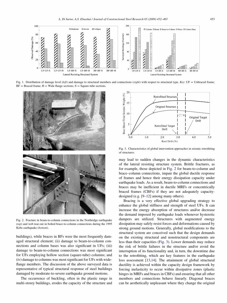
Fig. 2. Fracture in beam-to-column connections in the Northridge earthquake(top) and web tear-out in bolted brace-to-column connections during the 1995Kobe earthquake (bottom).
buildings), while braces in BFs were the most frequently dam-aged structural element; (ii) damage to beam-to-column con-nections and column bases was also significant in UFs; (iii)damage to beam-to-column connections was most significantfor UFs employing hollow section (square-tube) columns; and(iv) damage to columns was most significant for UFs with wide-flange members. The discussion of the above surveyed data isrepresentative of typical structural response of steel buildingsdamaged by moderate-to-severe earthquake ground motions.
The occurrence of buckling, often in the plastic range inmulti-storey buildings, erodes the capacity of the structure and
Fig. 3. Characteristics of global intervention approaches in seismic retrofittingof structures.
may lead to sudden changes in the dynamic characteristicsof the lateral resisting structure system. Brittle fractures, asfor example, those depicted in Fig. 2 for beam-to-column andbrace–column connections, impair the global ductile responseof frames and hence their energy dissipation capacity underearthquake loads. As a result, beam-to-column connections andbraces may be inefficient in ductile MRFs or concentricallybraced frames (CBFs) if they are not adequately capacity-designed (e.g. [9–12] among many others).
Bracing is a very effective global upgrading strategy toenhance the global stiffness and strength of steel UFs. It canincrease the energy absorption of structures and/or decreasethe demand imposed by earthquake loads whenever hystereticdampers are utilized. Structures with augmented energydissipation may safely resist forces and deformations caused bystrong ground motions. Generally, global modifications to thestructural system are conceived such that the design demandson the existing structural and nonstructural components areless than their capacities (Fig. 3). Lower demands may reducethe risk of brittle failures in the structure and/or avoid theinterruption of its functionality and, in turn, the downtime dueto the retrofitting, which are key features in the earthquakeloss assessment [13,14]. The attainment of global structuralductility is achieved within the capacity design framework byforcing inelasticity to occur within dissipative zones (plastichinges in MRFs and braces in CBFs) and ensuring that all othermembers and connections behave linearly. Diagonal bracescan be aesthetically unpleasant where they change the original
454 L. Di Sarno, A.S. Elnashai / Journal of Constructional Steel Research 65 (2009) 452–465
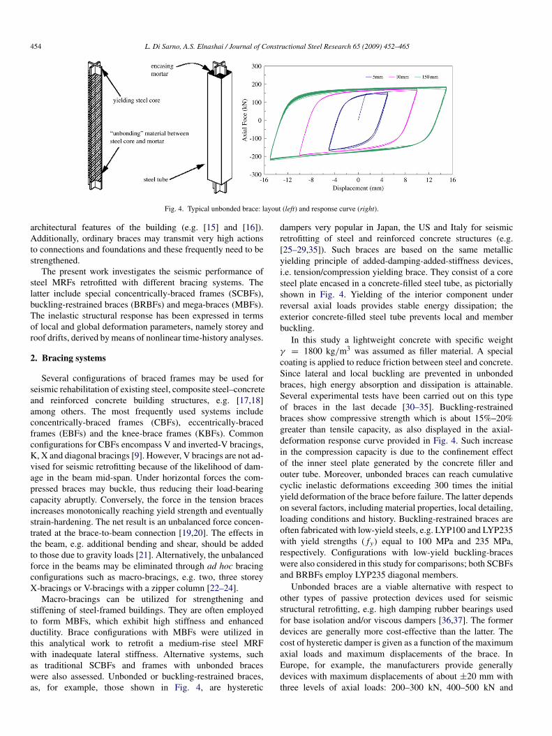
Fig. 4. Typical unbonded brace: layout (left) and response curve (right).
architectural features of the building (e.g. [15] and [16]).Additionally, ordinary braces may transmit very high actionsto connections and foundations and these frequently need to bestrengthened.
The present work investigates the seismic performance ofsteel MRFs retrofitted with different bracing systems. Thelatter include special concentrically-braced frames (SCBFs),buckling-restrained braces (BRBFs) and mega-braces (MBFs).The inelastic structural response has been expressed in termsof local and global deformation parameters, namely storey androof drifts, derived by means of nonlinear time-history analyses.
2. Bracing systems
Several configurations of braced frames may be used forseismic rehabilitation of existing steel, composite steel–concreteand reinforced concrete building structures, e.g. [17,18]among others. The most frequently used systems includeconcentrically-braced frames (CBFs), eccentrically-bracedframes (EBFs) and the knee-brace frames (KBFs). Commonconfigurations for CBFs encompass V and inverted-V bracings,K, X and diagonal bracings [9]. However, V bracings are not ad-vised for seismic retrofitting because of the likelihood of dam-age in the beam mid-span. Under horizontal forces the com-pressed braces may buckle, thus reducing their load-bearingcapacity abruptly. Conversely, the force in the tension bracesincreases monotonically reaching yield strength and eventuallystrain-hardening. The net result is an unbalanced force concen-trated at the brace-to-beam connection [19,20]. The effects inthe beam, e.g. additional bending and shear, should be addedto those due to gravity loads [21]. Alternatively, the unbalancedforce in the beams may be eliminated through ad hoc bracingconfigurations such as macro-bracings, e.g. two, three storeyX-bracings or V-bracings with a zipper column [22–24].
Macro-bracings can be utilized for strengthening andstiffening of steel-framed buildings. They are often employedto form MBFs, which exhibit high stiffness and enhancedductility. Brace configurations with MBFs were utilized inthis analytical work to retrofit a medium-rise steel MRFwith inadequate lateral stiffness. Alternative systems, suchas traditional SCBFs and frames with unbonded braceswere also assessed. Unbonded or buckling-restrained braces,as, for example, those shown in Fig. 4, are hysteretic
dampers very popular in Japan, the US and Italy for seismicretrofitting of steel and reinforced concrete structures (e.g.[25–29,35]). Such braces are based on the same metallicyielding principle of added-damping-added-stiffness devices,i.e. tension/compression yielding brace. They consist of a coresteel plate encased in a concrete-filled steel tube, as pictoriallyshown in Fig. 4. Yielding of the interior component underreversal axial loads provides stable energy dissipation; theexterior concrete-filled steel tube prevents local and memberbuckling.
In this study a lightweight concrete with specific weightγ = 1800 kg/m3 was assumed as filler material. A specialcoating is applied to reduce friction between steel and concrete.Since lateral and local buckling are prevented in unbondedbraces, high energy absorption and dissipation is attainable.Several experimental tests have been carried out on this typeof braces in the last decade [30–35]. Buckling-restrainedbraces show compressive strength which is about 15%–20%greater than tensile capacity, as also displayed in the axial-deformation response curve provided in Fig. 4. Such increasein the compression capacity is due to the confinement effectof the inner steel plate generated by the concrete filler andouter tube. Moreover, unbonded braces can reach cumulativecyclic inelastic deformations exceeding 300 times the initialyield deformation of the brace before failure. The latter dependson several factors, including material properties, local detailing,loading conditions and history. Buckling-restrained braces areoften fabricated with low-yield steels, e.g. LYP100 and LYP235with yield strengths ( fy) equal to 100 MPa and 235 MPa,respectively. Configurations with low-yield buckling-braceswere also considered in this study for comparisons; both SCBFsand BRBFs employ LYP235 diagonal members.
Unbonded braces are a viable alternative with respect toother types of passive protection devices used for seismicstructural retrofitting, e.g. high damping rubber bearings usedfor base isolation and/or viscous dampers [36,37]. The formerdevices are generally more cost-effective than the latter. Thecost of hysteretic damper is given as a function of the maximumaxial loads and maximum displacements of the brace. InEurope, for example, the manufacturers provide generallydevices with maximum displacements of about ±20 mm withthree levels of axial loads: 200–300 kN, 400–500 kN and
L. Di Sarno, A.S. Elnashai / Journal of Constructional Steel Research 65 (2009) 452–465 455
600–800 kN. For these devices the cost may vary between1500e (200 kN) and 3000e (600 kN).
3. Case studies
3.1. Description of the sample frames
A 9-storey steel MRF building was designed with lateralstiffness that does not comply with drift limitations imposedfor structural systems in earthquake-prone regions. The multi-storey frame has five 9144 mm-long bays. The interstoreyheight is 3962 mm for all but the first floor which is 5486 mmhigh. At the first and second storeys, beam span loads are equalto 14.88 kN/m and joint vertical loads are equal to 158 kNand 107 kN at interior and perimeter joints, respectively. Beamloads of 12.65 kN/m and joint vertical loads of 140 kN (interiorjoints) and 92 kN (exterior joints) were used at the roof. Thetotal vertical load of the frame for seismic combinations isWtot = 45 070 kN. Nominal yield strength equal to 345 MPa(50 ksi) was used for columns while girders have strengthequal to 248 MPa (36 ksi). The prototype MRF represents atypical perimeter frame of multi-storey residential buildings inareas with high earthquake hazard, e.g. Los Angeles (seismiczone 4), in California. The value of 0.40g was assumed forthe peak ground acceleration at the bedrock; the soil type forthe construction site is rock. The seismic base shear is equalto VB = 5803 kN and was estimated through the designprovisions in [38]. The assumed response modification factoris R = 8.50; the equivalent viscous damping is ξ = 5%.The natural period of vibration used to evaluate VB is 1.28seconds; it was computed as a function of the frame totalheight, i.e. H = 37,182 mm. The fundamental period derivedby eigenvalue analysis is 2.05 s, about 60% higher than thevalue derived by utilizing the simplified code expression. Itis instructive to note, however, that seismic codes of practicetend to underestimate the fundamental period of vibration toaccount for the stiffening effects of nonstructural elements,e.g. partition walls and infills. Such effects are of primaryimportance for steel structures, which exhibit relatively lowhorizontal stiffness. The underestimation of the natural periodleads to conservative design assumptions, e.g. higher seismicbase shear and, in turn, larger storey lateral displacement drifts.The reliability/redundancy factor ρ was assumed equal to 1.25to account for the perimeter configuration of the MRF (lowredundancy). The maximum lateral displacement d of the framewas found at the first storey; the estimated maximum interstoreydrift d/h is 3.96%. The latter value exceeds the recommendeddrift provided by [38] for limit state of ‘near collapse’,i.e. 3.8%. On the other hand, data collected from severalpost-earthquake reconnaissance reports have demonstrated thatvalues of d/h equal to 3.0%, or even smaller, should be utilizedin seismic design to prevent structural collapse of framedsystems [39].
Bracing was utilized as a means to retrofit the MRF withinadequate lateral stiffness. The design target was the reductionof the interstorey drift d/h at first storey of the prototypeunbraced structure. In so doing, different configurations and
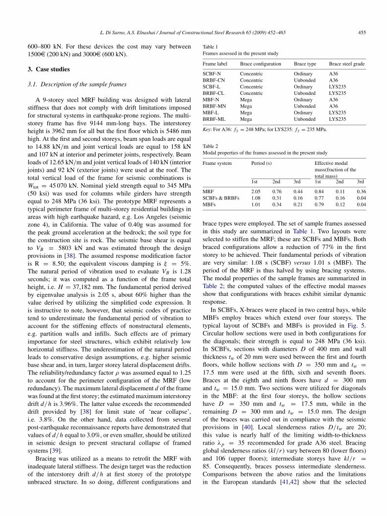
Table 1Frames assessed in the present study
Frame label Brace configuration Brace type Brace steel grade
SCBF-N Concentric Ordinary A36BRBF-CN Concentric Unbonded A36SCBF-L Concentric Ordinary LYS235BRBF-CL Concentric Unbonded LYS235MBF-N Mega Ordinary A36BRBF-MN Mega Unbonded A36MBF-L Mega Ordinary LYS235BRBF-ML Mega Unbonded LYS235
Key: For A36: fy = 248 MPa; for LYS235: fy = 235 MPa.
Table 2Modal properties of the frames assessed in the present study
Frame system Period (s) Effective modalmass(fraction of thetotal mass)
1st 2nd 3rd 1st 2nd 3rd
MRF 2.05 0.76 0.44 0.84 0.11 0.36SCBFs & BRBFs 1.08 0.31 0.16 0.77 0.16 0.04MBFs 1.01 0.34 0.21 0.79 0.12 0.04
brace types were employed. The set of sample frames assessedin this study are summarized in Table 1. Two layouts wereselected to stiffen the MRF; these are SCBFs and MBFs. Bothbraced configurations allow a reduction of 77% in the firststorey to be achieved. Their fundamental periods of vibrationare very similar: 1.08 s (SCBF) versus 1.01 s (MBF). Theperiod of the MRF is thus halved by using bracing systems.The modal properties of the sample frames are summarized inTable 2; the computed values of the effective modal massesshow that configurations with braces exhibit similar dynamicresponse.
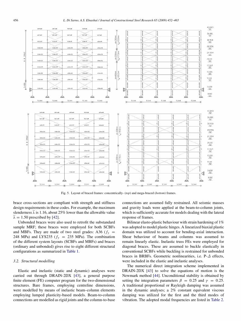
In SCBFs, X-braces were placed in two central bays, whileMBFs employ braces which extend over four storeys. Thetypical layout of SCBFs and MBFs is provided in Fig. 5.Circular hollow sections were used in both configurations forthe diagonals; their strength is equal to 248 MPa (36 ksi).In SCBFs, sections with diameters D of 400 mm and wallthickness tw of 20 mm were used between the first and fourthfloors, while hollow sections with D = 350 mm and tw =17.5 mm were used at the fifth, sixth and seventh floors.Braces at the eighth and ninth floors have d = 300 mmand tw = 15.0 mm. Two sections were utilized for diagonalsin the MBF: at the first four storeys, the hollow sectionshave D = 350 mm and tw = 17.5 mm, while in theremaining D = 300 mm and tw = 15.0 mm. The designof the braces was carried out in compliance with the seismicprovisions in [40]. Local slenderness ratios D/tw are 20;this value is nearly half of the limiting width-to-thicknessratio λp = 35 recommended for grade A36 steel. Bracingglobal slenderness ratios (kl/r) vary between 80 (lower floors)and 106 (upper floors); intermediate storeys have kl/r =85. Consequently, braces possess intermediate slenderness.Comparisons between the above ratios and the limitationsin the European standards [41,42] show that the selected
456 L. Di Sarno, A.S. Elnashai / Journal of Constructional Steel Research 65 (2009) 452–465
Fig. 5. Layout of braced frames: concentrically- (top) and mega-braced (bottom) frames.
brace cross-sections are compliant with strength and stiffnessdesign requirements in these codes. For example, the maximumslenderness λ is 1.16, about 25% lower than the allowable valueλ = 1.50 prescribed by [42].
Unbonded braces were also used to retrofit the substandardsample MRF; these braces were employed for both SCBFsand MBFs. They are made of two steel grades: A36 ( fy =
248 MPa) and LYS235 ( fy = 235 MPa). The combinationof the different system layouts (SCBFs and MBFs) and braces(ordinary and unbonded) gives rise to eight different structuralconfigurations as summarized in Table 1.
3.2. Structural modelling
Elastic and inelastic (static and dynamic) analyses werecarried out through DRAIN-2DX [43], a general purposefinite element (FE) computer program for the two-dimensionalstructures. Bare frames, employing centreline dimensions,were modelled by means of inelastic beam–column elementsemploying lumped plasticity-based models. Beam-to-columnconnections are modelled as rigid joints and the column-to-base
connections are assumed fully restrained. All seismic massesand gravity loads were applied at the beam-to-column joints,which is sufficiently accurate for models dealing with the lateralresponse of frames.
Bilinear elasto-plastic behaviour with strain hardening of 1%was adopted to model plastic hinges. A linearized biaxial plasticdomain was utilized to account for bending-axial interaction.Shear behaviour of beams and columns was assumed toremain linearly elastic. Inelastic truss FEs were employed fordiagonal braces. These are assumed to buckle elastically inconventional SCBFs while buckling is restrained for unbondedbraces in BRBFs. Geometric nonlinearities, i.e. P-∆ effects,were included in the elastic and inelastic analyses.
The numerical direct integration scheme implemented inDRAIN-2DX [43] to solve the equations of motion is theNewmark method [44]. Unconditional stability is obtained bysetting the integration parameters β = 0.25 and γ = 0.25.A traditional proportional or Rayleigh damping was assumedin the dynamic analyses; a 2% constant equivalent viscousdamping was utilized for the first and the third modes ofvibration. The adopted modal frequencies are listed in Table 2.
L. Di Sarno, A.S. Elnashai / Journal of Constructional Steel Research 65 (2009) 452–465 457
Fig. 7. Duration of the sample earthquake records.
The duration of the ground motion and the correspondingnumber of cycles are of paramount importance for the assess-ment of low-cycle fatigue damage in structural earthquake en-gineering applications (e.g. [47]). The selected records exhibitdifferent durations as displayed in Fig. 7 in which the estimatedof the bracketed, significant and uniform durations are summa-rized. It is noted that the definitions of significant and uniformdurations lead to similar values for all earthquakes. This out-come depends on the engineering seismology properties of thesample accelerograms (e.g. [48]).
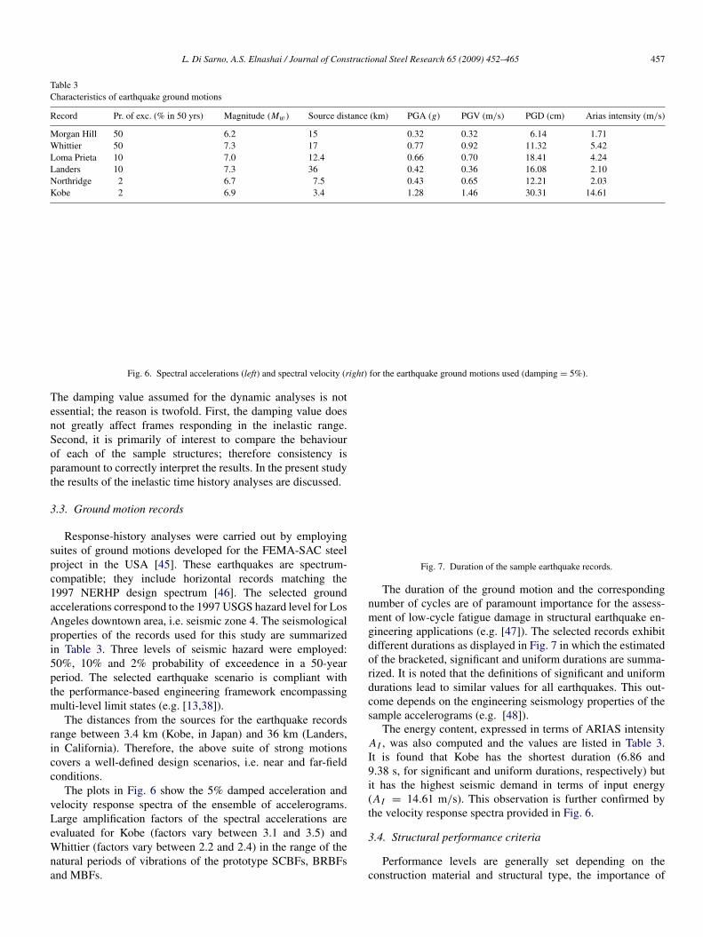
The energy content, expressed in terms of ARIAS intensityAI , was also computed and the values are listed in Table 3.It is found that Kobe has the shortest duration (6.86 and9.38 s, for significant and uniform durations, respectively) butit has the highest seismic demand in terms of input energy(AI = 14.61 m/s). This observation is further confirmed bythe velocity response spectra provided in Fig. 6.
3.4. Structural performance criteria
Performance levels are generally set depending on theconstruction material and structural type, the importance of
Table 3Characteristics of earthquake ground motions
Record Pr. of exc. (% in 50 yrs) Magnitude (Mw) Source distance (km) PGA (g) PGV (m/s) PGD (cm) Arias intensity (m/s)
Morgan Hill 50 6.2 15 0.32 0.32 6.14 1.71Whittier 50 7.3 17 0.77 0.92 11.32 5.42Loma Prieta 10 7.0 12.4 0.66 0.70 18.41 4.24Landers 10 7.3 36 0.42 0.36 16.08 2.10Northridge 2 6.7 7.5 0.43 0.65 12.21 2.03Kobe 2 6.9 3.4 1.28 1.46 30.31 14.61
Fig. 6. Spectral accelerations (left) and spectral velocity (right) for the earthquake ground motions used (damping = 5%).
The damping value assumed for the dynamic analyses is notessential; the reason is twofold. First, the damping value doesnot greatly affect frames responding in the inelastic range.Second, it is primarily of interest to compare the behaviourof each of the sample structures; therefore consistency isparamount to correctly interpret the results. In the present studythe results of the inelastic time history analyses are discussed.
3.3. Ground motion records
Response-history analyses were carried out by employingsuites of ground motions developed for the FEMA-SAC steelproject in the USA [45]. These earthquakes are spectrum-compatible; they include horizontal records matching the1997 NERHP design spectrum [46]. The selected groundaccelerations correspond to the 1997 USGS hazard level for LosAngeles downtown area, i.e. seismic zone 4. The seismologicalproperties of the records used for this study are summarizedin Table 3. Three levels of seismic hazard were employed:50%, 10% and 2% probability of exceedence in a 50-yearperiod. The selected earthquake scenario is compliant withthe performance-based engineering framework encompassingmulti-level limit states (e.g. [13,38]).
The distances from the sources for the earthquake recordsrange between 3.4 km (Kobe, in Japan) and 36 km (Landers,in California). Therefore, the above suite of strong motionscovers a well-defined design scenarios, i.e. near and far-fieldconditions.
The plots in Fig. 6 show the 5% damped acceleration andvelocity response spectra of the ensemble of accelerograms.Large amplification factors of the spectral accelerations areevaluated for Kobe (factors vary between 3.1 and 3.5) andWhittier (factors vary between 2.2 and 2.4) in the range of thenatural periods of vibrations of the prototype SCBFs, BRBFsand MBFs.


Related Documents