BR-250 / BR-250SS / M2-250 SERVICE MANUAL Manufactured by PGO of Motive Power Industry Co., Ltd

Welcome message from author
This document is posted to help you gain knowledge. Please leave a comment to let me know what you think about it! Share it to your friends and learn new things together.
Transcript
BR-250 / BR-250SS / M2-250 SERVICE MANUAL
Manufactured by PGO
of Motive Power Industry Co., Ltd
1. INSPECTION/ADJUSTMENT
0
BR & M2 250 ENGINE
1 __________________________________________________________________________________
__________________________________________________________________________________
__________________________________________________________________________________
__________________________________________________________________________________
__________________________________________________________________________________
INSPECTION/ADJUSTMENT
__________________________________________________________________________________
SERVICE INFORMATION ------------------------------------------------- 1- 1 MAINTENANCE SCHEDULE---------------------------------------------- 1- 2 FUEL LINE/FUEL FILTER-------------------------------------------------- 1- 3 THROTTLE OPERATION-------------------------------------------------- 1- 3 ENGINE OIL-------------------------------------------------------------------- 1- 4 AIR CLEANER----------------------------------------------------------------- 1- 5 SPARK PLUG ------------------------------------------------------------------ 1- 5 VALVE CLEARANCE-------------------------------------------------------- 1- 6 CARBURETOR IDLE SPEED---------------------------------------------- 1- 6 CYLINDER COMPRESSION----------------------------------------------- 1- 7 FINAL REDUCTION GEAR OIL------------------------------------------ 1- 8 DRIVE BELT ------------------------------------------------------------------- 1- 8 HEADLIGHT AIM------------------------------------------------------------- 1- 9 CLUTCH SHOE WEAR------------------------------------------------------ 1- 9 COOLING SYSTEM---------------------------------------------------------- 1- 9 BRAKE SYSTEM-------------------------------------------------------------- 1-10 NUTS/BOLTS/FASTENERS------------------------------------------------ 1-11 WHEELS/TIRES --------------------------------------------------------------- 1-11 STEERING HANDLEBAR -------------------------------------------------- 1-11 SUSPENSION------------------------------------------------------------------ 1-11
1
1. INSPECTION/ADJUSTMENT
1
BR & M2 250 ENGINE SERVICE INFORMATION
GENERAL
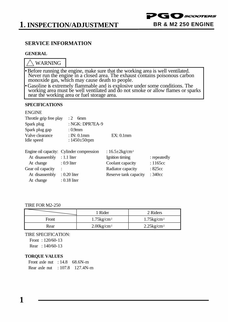
! WARNING •Before running the engine, make sure that the working area is well ventilated.
Never run the engine in a closed area. The exhaust contains poisonous carbon monoxide gas, which may cause death to people.
•Gasoline is extremely flammable and is explosive under some conditions. The working area must be well ventilated and do not smoke or allow flames or sparks near the working area or fuel storage area.
SPECIFICATIONS ENGINE Throttle grip free play : 2∼6mm Spark plug : NGK: DPR7EA-9 Spark plug gap : 0.9mm Valve clearance : IN: 0.1mm EX: 0.1mm Idle speed : 1450±50rpm
Engine oil capacity: Cylinder compression : 16.5±2kg/cm² At disassembly : 1.1 liter Ignition timing : repeatedly At change : 0.9 liter Coolant capacity : 1165cc Gear oil capacity : Radiator capacity : 825cc At disassembly : 0.20 liter Reserve tank capacity : 340cc At change : 0.18 liter TIRE FOR M2-250
1 Rider 2 Riders Front 1.75kg/cm² 1.75kg/cm² Rear 2.00kg/cm² 2.25kg/cm²
TIRE SPECIFICATION: Front : 120/60-13 Rear : 140/60-13 TORQUE VALUES Front axle nut : 14.8∼68.6N-m Rear axle nut : 107.8∼127.4N-m
1. INSPECTION/ADJUSTMENT
2
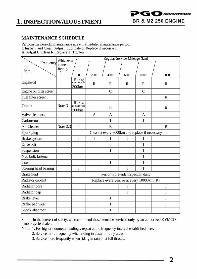
BR & M2 250 ENGINE MAINTENANCE SCHEDULE Perform the periodic maintenance at each scheduled maintenance period. I: Inspect, and Clean, Adjust, Lubricate or Replace if necessary. A: Adjust C: Clean R: Replace T: Tighten
Regular Service Mileage (km) Frequency Item
comes first ð ò
1000 2000 4000
6000
8000
10000
Engine oil R New
motorcycle 300km
R
R
R
R
R
Engine oil filter screen C C Fuel filter screen R
Gear oil Note 3 R New motorcycle 300km
R
R
Valve clearance A A A Carburetor I I Air Cleaner Note 2,3 I R R Spark plug Clean at every 3000km and replace if necessary Brake system I I I I I I Drive belt I Suspension I I Nut, bolt, fastener I Tire I I Steering head bearing I I I Brake fluid Perform pre-ride inspection daily Radiator coolant Replace every year or at every 10000km (R) Radiator core I I Radiator cap I I Brake lever I I Brake pad wear I I Shock absorber I I • In the interest of safety, we recommend these items be serviced only by an authorized KYMCO
motorcycle dealer. Note: 1. For higher odometer readings, repeat at the frequency interval established here. 2. Service more frequently when riding in dusty or rainy areas. 3. Service more frequently when riding in rain or at full throttle.
Whichever
1. INSPECTION/ADJUSTMENT
3
BR & M2 250 ENGINE
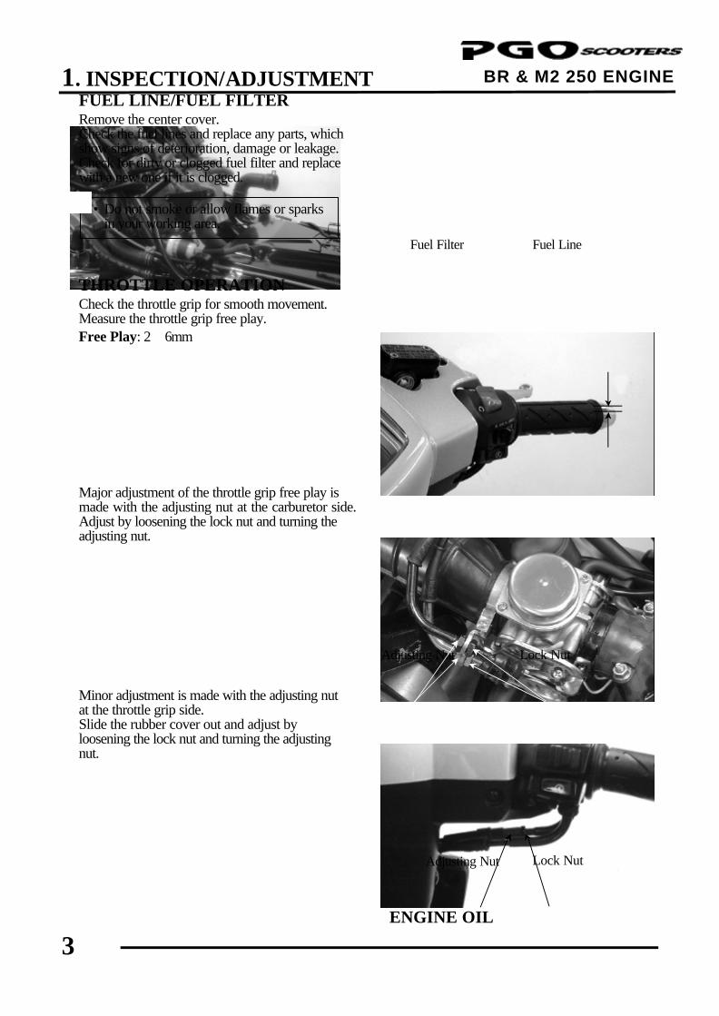
FUEL LINE/FUEL FILTER Remove the center cover. Check the fuel lines and replace any parts, which show signs of deterioration, damage or leakage. Check for dirty or clogged fuel filter and replace with a new one if it is clogged. THROTTLE OPERATION Check the throttle grip for smooth movement. Measure the throttle grip free play. Free Play: 2∼6mm Major adjustment of the throttle grip free play is made with the adjusting nut at the carburetor side. Adjust by loosening the lock nut and turning the adjusting nut. Minor adjustment is made with the adjusting nut at the throttle grip side. Slide the rubber cover out and adjust by loosening the lock nut and turning the adjusting nut.
ENGINE OIL
Lock Nut
Adjusting Nut
Fuel Filter
• Do not smoke or allow flames or sparks in your working area.
*
Fuel Line
Lock Nut
Adjusting Nut
1. INSPECTION/ADJUSTMENT
4
BR & M2 250 ENGINE
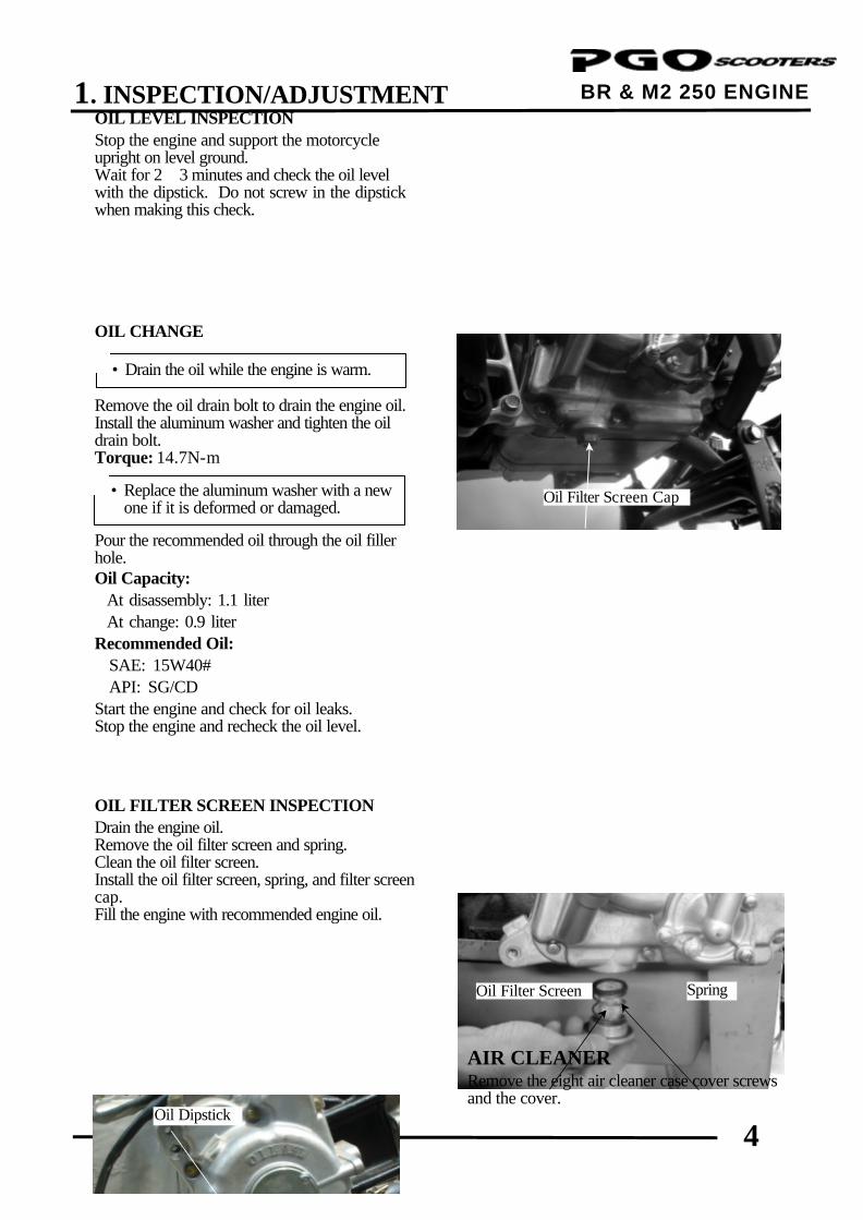
OIL LEVEL INSPECTION Stop the engine and support the motorcycle upright on level ground. Wait for 2∼3 minutes and check the oil level with the dipstick. Do not screw in the dipstick when making this check. OIL CHANGE Remove the oil drain bolt to drain the engine oil. Install the aluminum washer and tighten the oil drain bolt. Torque: 14.7N-m Pour the recommended oil through the oil filler hole. Oil Capacity: At disassembly: 1.1 liter At change: 0.9 liter Recommended Oil: SAE: 15W40# API: SG/CD Start the engine and check for oil leaks. Stop the engine and recheck the oil level. OIL FILTER SCREEN INSPECTION Drain the engine oil. Remove the oil filter screen and spring. Clean the oil filter screen. Install the oil filter screen, spring, and filter screen cap. Fill the engine with recommended engine oil.
AIR CLEANER Remove the eight air cleaner case cover screws and the cover.
Spring
• Drain the oil while the engine is warm. *
• Replace the aluminum washer with a new one if it is deformed or damaged.
*
Oil Filter Screen
Oil Dipstick
Oil Filter Screen Cap
1. INSPECTION/ADJUSTMENT
5
BR & M2 250 ENGINE
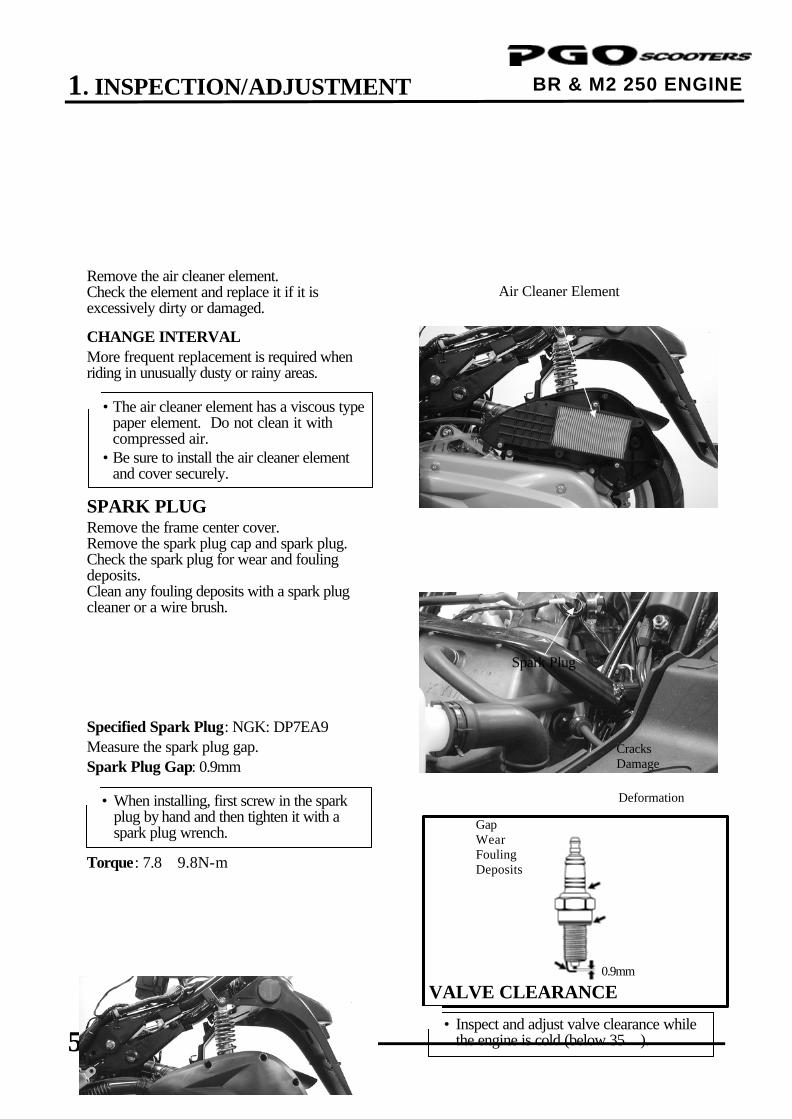
Remove the air cleaner element. Check the element and replace it if it is excessively dirty or damaged. CHANGE INTERVAL More frequent replacement is required when riding in unusually dusty or rainy areas. SPARK PLUG Remove the frame center cover. Remove the spark plug cap and spark plug. Check the spark plug for wear and fouling deposits. Clean any fouling deposits with a spark plug cleaner or a wire brush.
Specified Spark Plug: NGK: DP7EA9 Measure the spark plug gap. Spark Plug Gap: 0.9mm Torque: 7.8∼9.8N-m
VALVE CLEARANCE
} Gap Wear Fouling Deposits
Spark Plug
Cracks Damage
• The air cleaner element has a viscous type paper element. Do not clean it with compressed air.
• Be sure to install the air cleaner element and cover securely.
*
• When installing, first screw in the spark plug by hand and then tighten it with a spark plug wrench.
* Deformation
• Inspect and adjust valve clearance while the engine is cold (below 35).
*
0.9mm
Air Cleaner Element
1. INSPECTION/ADJUSTMENT
6
BR & M2 250 ENGINE
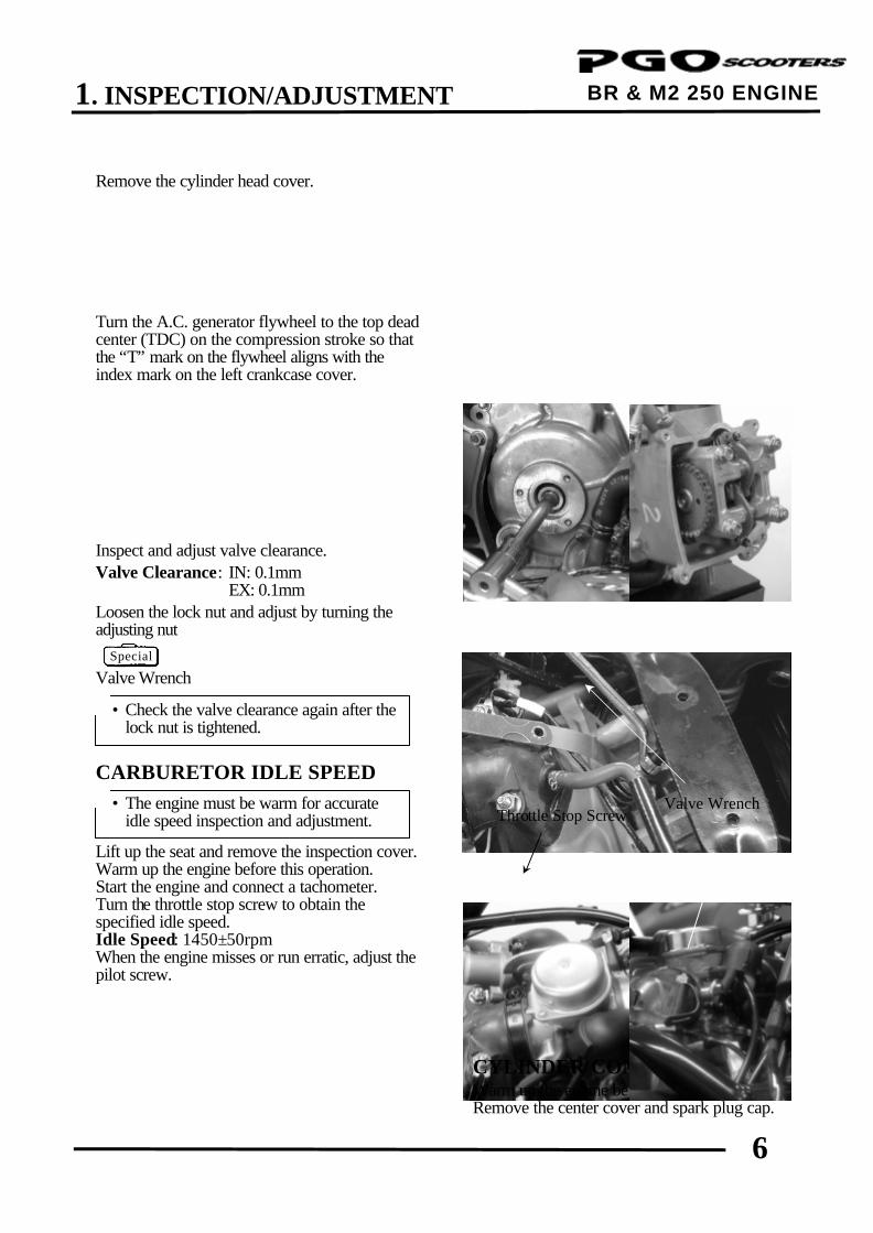
Remove the cylinder head cover. Turn the A.C. generator flywheel to the top dead center (TDC) on the compression stroke so that the “T” mark on the flywheel aligns with the index mark on the left crankcase cover. Inspect and adjust valve clearance. Valve Clearance: IN: 0.1mm EX: 0.1mm Loosen the lock nut and adjust by turning the adjusting nut
Valve Wrench CARBURETOR IDLE SPEED Lift up the seat and remove the inspection cover. Warm up the engine before this operation. Start the engine and connect a tachometer. Turn the throttle stop screw to obtain the specified idle speed. Idle Speed: 1450±50rpm When the engine misses or run erratic, adjust the pilot screw.
CYLINDER COMPRESSION Warm up the engine before compression test. Remove the center cover and spark plug cap.
Throttle Stop Screw
Pilot Screw
• Check the valve clearance again after the lock nut is tightened.
*
• The engine must be warm for accurate idle speed inspection and adjustment.
*
Top Dead Center
Valve Wrench
Special
1. INSPECTION/ADJUSTMENT
7
BR & M2 250 ENGINE
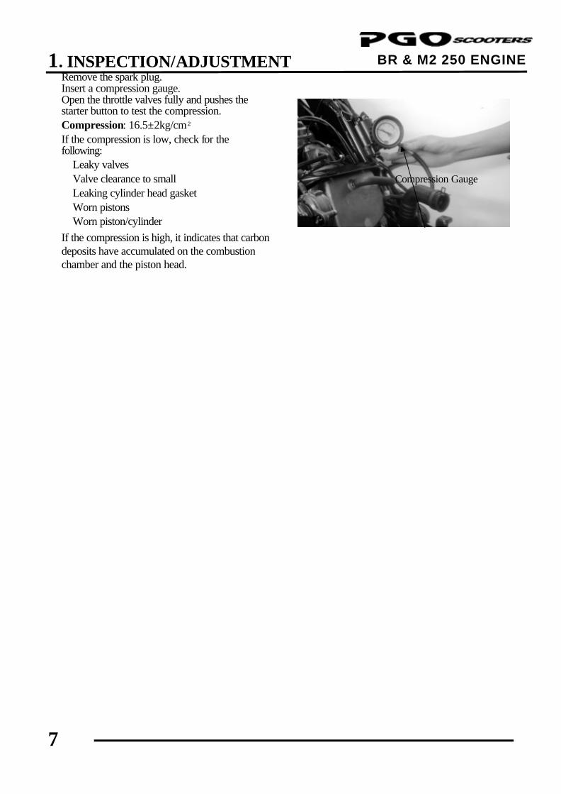
Remove the spark plug. Insert a compression gauge. Open the throttle valves fully and pushes the starter button to test the compression. Compression: 16.5±2kg/cm² If the compression is low, check for the following: ‧Leaky valves ‧Valve clearance to small ‧Leaking cylinder head gasket ‧Worn pistons ‧Worn piston/cylinder If the compression is high, it indicates that carbon deposits have accumulated on the combustion chamber and the piston head.
Compression Gauge

1. INSPECTION/ADJUSTMENT
8
BR & M2 250 ENGINE
FINAL REDUCTION GEAR OIL Stop the engine and remove the oil checks bolt. The oil level shall be at the oil check blowhole. If the oil level is low, add the recommended oil SAE90# to the proper level. Install the oil check bolt. OIL CHANGE Remove the oil check bolt. Removes the oil drains bolt and drain the oil thoroughly. Install the oil drain bolt. Torque: 9.8N-m Fill the final reduction with the recommended oil SAE90#. Gear Oil Capacity: At disassembly : 200cc At change : 180cc Reinstall the oil check bolt and check for oil leaks. DRIVE BELT Remove the left crankcase cover. Inspect the drive belt for cracks or excessive wear. Replace the drive belt with a new one if necessary and in accordance with the Maintenance Schedule.
HEADLIGHT AIM Turn the ignition switch ON.
Drive Belt
• Place the motorcycle on its main stand on level ground.
*
Oil Drain Bolt/Sealing Washer
• Make sure that the sealing washer is in good condition.
*
• Make sure that the sealing washer is in good condition.
*
1. INSPECTION/ADJUSTMENT
9
BR & M2 250 ENGINE
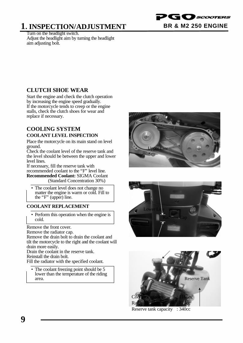
Turn on the headlight switch. Adjust the headlight aim by turning the headlight aim adjusting bolt. CLUTCH SHOE WEAR Start the engine and check the clutch operation by increasing the engine speed gradually. If the motorcycle tends to creep or the engine stalls, check the clutch shoes for wear and replace if necessary. COOLING SYSTEM COOLANT LEVEL INSPECTION Place the motorcycle on its main stand on level ground. Check the coolant level of the reserve tank and the level should be between the upper and lower level lines. If necessary, fill the reserve tank with recommended coolant to the “F” level line. Recommended Coolant: SIGMA Coolant (Standard Concentration 30%) COOLANT REPLACEMENT Remove the front cover. Remove the radiator cap. Remove the drain bolt to drain the coolant and tilt the motorcycle to the right and the coolant will drain more easily. Drain the coolant in the reserve tank. Reinstall the drain bolt. Fill the radiator with the specified coolant.
Coolant capacity : 1165cc Radiator capacity : 825cc Reserve tank capacity : 340cc
Lower Line
Upper Line
Radiator Cap
• The coolant level does not change no matter the engine is warm or cold. Fill to the “F” (upper) line.
*
• The coolant freezing point should be 5 lower than the temperature of the riding area.
*
• Perform this operation when the engine is cold.
*
Reserve Tank
1. INSPECTION/ADJUSTMENT
10
BR & M2 250 ENGINE
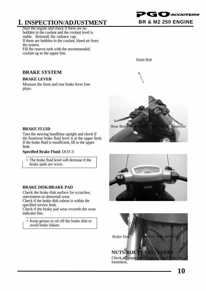
Start the engine and check if there are no bubbles in the coolant and the coolant level is stable. Reinstall the radiator cap. If there are bubbles in the coolant, bleed air from the system. Fill the reserve tank with the recommended coolant up to the upper line. BRAKE SYSTEM BRAKE LEVER Measure the front and rear brake lever free plays. BRAKE FLUID Turn the steering handlebar upright and check if the front/rear brake fluid level is at the upper limit. If the brake fluid is insufficient, fill to the upper limit. Specified Brake Fluid: DOT-3 BRAKE DISK/BRAKE PAD Check the brake disk surface for scratches, unevenness or abnormal wear. Check if the brake disk rubout is within the specified service limit. Check if the brake pad wear exceeds the wear indicator line.
NUTS/BOLTS/FASTENERS Check all important chassis nuts and bolts for looseness.
Wear Indicator Line
Drain Bolt
Rear Brake Reservoir
Brake Disk
• The brake fluid level will decrease if the brake pads are worn.
*
• Keep grease or oil off the brake disk to avoid brake failure.
*
Front Brake Reservoir
1. INSPECTION/ADJUSTMENT
11
BR & M2 250 ENGINE Tighten them to their specified torque values if any looseness is found. WHEELS/TIRES Check the tires for cuts, imbedded nails or other damages. Check the tire pressure. Tire Pressure
1 Rider 2 Riders
Front 1.75kg/cm² 1.75kg/cm²
Rear 2.00kg/cm² 2.25kg/cm²
STEERING HANDLEBAR Raise the front wheel off the ground and check that the steering handlebar rotates freely. If the handlebar moves unevenly, binds, or has vertical movement, adjust the steering head bearing. SUSPENSION Check the action of the front/rear shock absorbers by compressing them several times. Check the entire shock absorber assembly for oil leaks looseness or damage. Jack the rear wheels off the ground and move the rear wheel sideways with force to see if the engine hanger bushings are worn. Replace the engine hanger bushings if there is any looseness.
• Tire pressure should be checked when tires are cold.
*

2. INSPECTION/ADJUSTMENT
0
BR 250 ENGINE
1 __________________________________________________________________________________
__________________________________________________________________________________
__________________________________________________________________________________
__________________________________________________________________________________
__________________________________________________________________________________
INSPECTION/ADJUSTMENT
__________________________________________________________________________________
SERVICE INFORMATION ------------------------------------------------- 2- 1 MAINTENANCE SCHEDULE---------------------------------------------- 2- 2 FUEL LINE/FUEL FILTER-------------------------------------------------- 2- 3 THROTTLE OPERATION-------------------------------------------------- 2- 3 ENGINE OIL-------------------------------------------------------------------- 2- 4 AIR CLEANER----------------------------------------------------------------- 2- 5 SPARK PLUG ------------------------------------------------------------------ 2- 5 VALVE CLEARANCE-------------------------------------------------------- 2- 6 CARBURETOR IDLE SPEED---------------------------------------------- 2- 6 CYLINDER COMPRESSION----------------------------------------------- 2- 7 FINAL REDUCTION GEAR OIL------------------------------------------ 2- 8 DRIVE BELT ------------------------------------------------------------------- 2- 8 HEADLIGHT AIM------------------------------------------------------------- 2- 9 CLUTCH SHOE WEAR------------------------------------------------------ 2- 9 COOLING SYSTEM---------------------------------------------------------- 2- 9 BRAKE SYSTEM-------------------------------------------------------------- 2-10 NUTS/BOLTS/FASTENERS------------------------------------------------ 2-11 WHEELS/TIRES --------------------------------------------------------------- 2-11 STEERING HANDLEBAR -------------------------------------------------- 2-11 SUSPENSION------------------------------------------------------------------ 2-11
2
2. INSPECTION/ADJUSTMENT
1
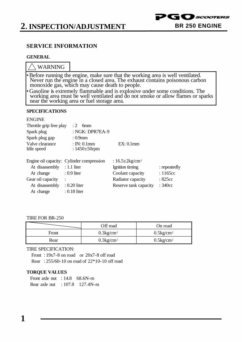
BR 250 ENGINE SERVICE INFORMATION
GENERAL
! WARNING •Before running the engine, make sure that the working area is well ventilated.
Never run the engine in a closed area. The exhaust contains poisonous carbon monoxide gas, which may cause death to people.
•Gasoline is extremely flammable and is explosive under some conditions. The working area must be well ventilated and do not smoke or allow flames or sparks near the working area or fuel storage area.
SPECIFICATIONS ENGINE Throttle grip free play : 2∼6mm Spark plug : NGK: DPR7EA-9 Spark plug gap : 0.9mm Valve clearance : IN: 0.1mm EX: 0.1mm Idle speed : 1450±50rpm
Engine oil capacity: Cylinder compression : 16.5±2kg/cm² At disassembly : 1.1 liter Ignition timing : repeatedly At change : 0.9 liter Coolant capacity : 1165cc Gear oil capacity : Radiator capacity : 825cc At disassembly : 0.20 liter Reserve tank capacity : 340cc At change : 0.18 liter TIRE FOR BR-250
Off road On road Front 0.3kg/cm² 0.5kg/cm² Rear 0.3kg/cm² 0.5kg/cm²
TIRE SPECIFICATION: Front : 19x7-8 on road or 20x7-8 off road Rear : 255/60-10 on road of 22*10-10 off road TORQUE VALUES Front axle nut : 14.8∼68.6N-m Rear axle nut : 107.8∼127.4N-m
2. INSPECTION/ADJUSTMENT
2
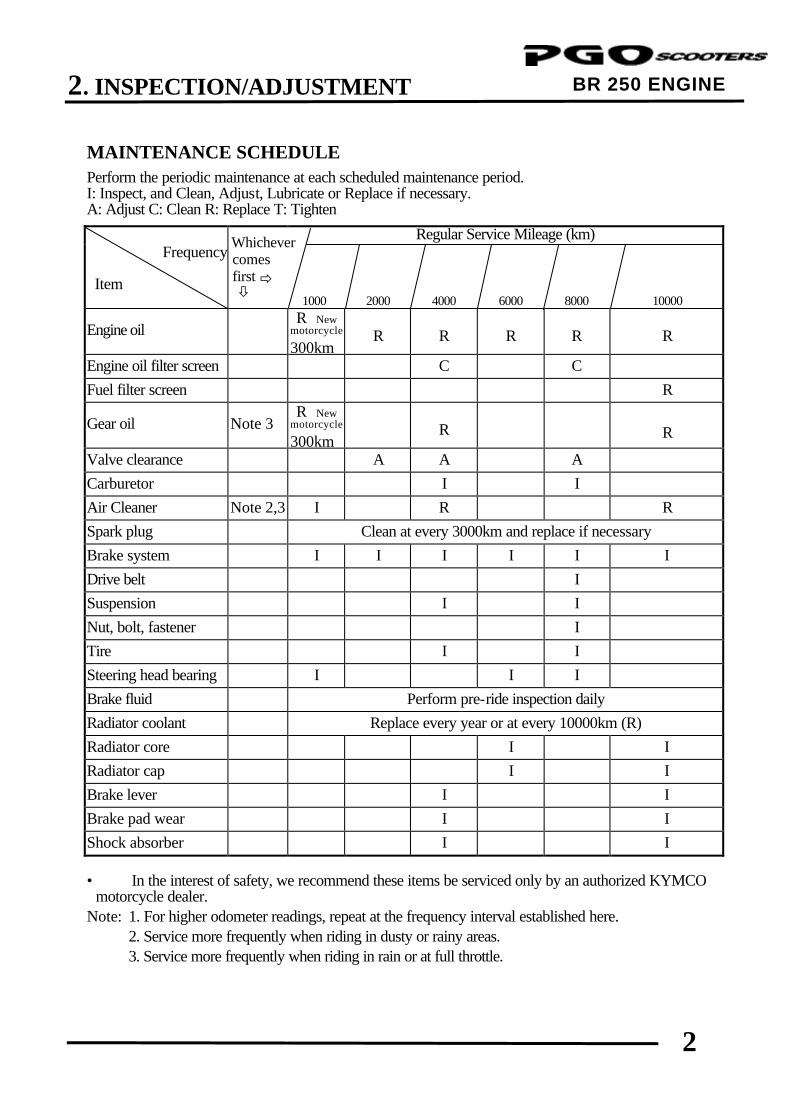
BR 250 ENGINE MAINTENANCE SCHEDULE Perform the periodic maintenance at each scheduled maintenance period. I: Inspect, and Clean, Adjust, Lubricate or Replace if necessary. A: Adjust C: Clean R: Replace T: Tighten
Regular Service Mileage (km) Frequency Item
comes first ð ò
1000 2000 4000
6000
8000
10000
Engine oil R New
motorcycle 300km
R
R
R
R
R
Engine oil filter screen C C Fuel filter screen R
Gear oil Note 3 R New motorcycle 300km
R
R
Valve clearance A A A Carburetor I I Air Cleaner Note 2,3 I R R Spark plug Clean at every 3000km and replace if necessary Brake system I I I I I I Drive belt I Suspension I I Nut, bolt, fastener I Tire I I Steering head bearing I I I Brake fluid Perform pre-ride inspection daily Radiator coolant Replace every year or at every 10000km (R) Radiator core I I Radiator cap I I Brake lever I I Brake pad wear I I Shock absorber I I • In the interest of safety, we recommend these items be serviced only by an authorized KYMCO
motorcycle dealer. Note: 1. For higher odometer readings, repeat at the frequency interval established here. 2. Service more frequently when riding in dusty or rainy areas. 3. Service more frequently when riding in rain or at full throttle.
Whichever
2. INSPECTION/ADJUSTMENT
3
BR 250 ENGINE
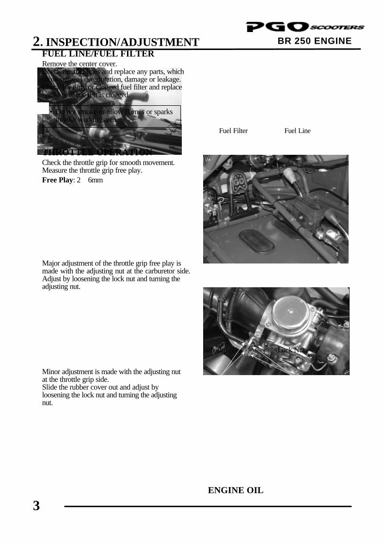
FUEL LINE/FUEL FILTER Remove the center cover. Check the fuel lines and replace any parts, which show signs of deterioration, damage or leakage. Check for dirty or clogged fuel filter and replace with a new one if it is clogged. THROTTLE OPERATION Check the throttle grip for smooth movement. Measure the throttle grip free play. Free Play: 2∼6mm Major adjustment of the throttle grip free play is made with the adjusting nut at the carburetor side. Adjust by loosening the lock nut and turning the adjusting nut. Minor adjustment is made with the adjusting nut at the throttle grip side. Slide the rubber cover out and adjust by loosening the lock nut and turning the adjusting nut.
ENGINE OIL
Lock Nut
Fuel Filter
• Do not smoke or allow flames or sparks in your working area.
*
Fuel Line
Adjusting Nut

2. INSPECTION/ADJUSTMENT
4
BR 250 ENGINE
OIL LEVEL INSPECTION Stop the engine and support the motorcycle upright on level ground. Wait for 2∼3 minutes and check the oil level with the dipstick. Do not screw in the dipstick when making this check. OIL CHANGE Remove the oil drain bolt to drain the engine oil. Install the aluminum washer and tighten the oil drain bolt. Torque: 14.7N-m Pour the recommended oil through the oil filler hole. Oil Capacity: At disassembly: 1.1 liter At change: 0.9 liter Recommended Oil: SAE: 15W40# API: SG/CD Start the engine and check for oil leaks. Stop the engine and recheck the oil level. OIL FILTER SCREEN INSPECTION Drain the engine oil. Remove the oil filter screen and spring. Clean the oil filter screen. Install the oil filter screen, spring, and filter screen cap. Fill the engine with recommended engine oil.
AIR CLEANER Remove the eight air cleaner case cover screws and the cover.
Spring
• Drain the oil while the engine is warm. *
• Replace the aluminum washer with a new one if it is deformed or damaged.
*
Oil Filter Screen
Oil Dipstick
Oil Filter Screen Cap
2. INSPECTION/ADJUSTMENT
5
BR 250 ENGINE
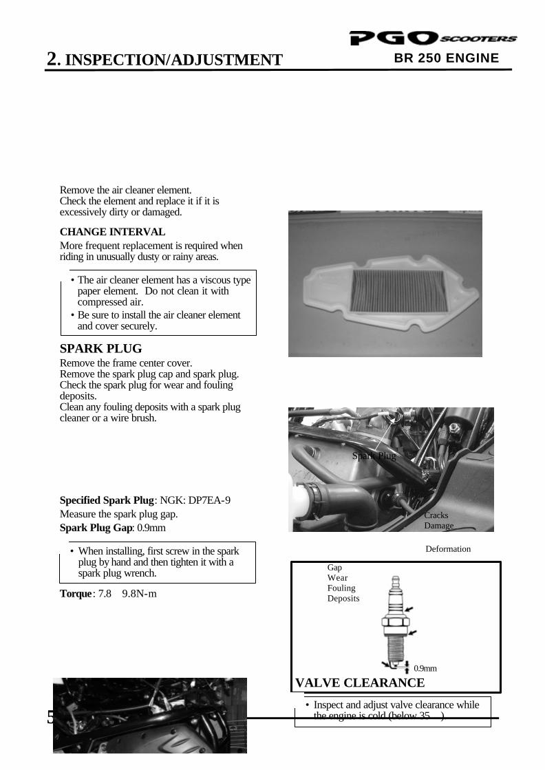
Remove the air cleaner element. Check the element and replace it if it is excessively dirty or damaged. CHANGE INTERVAL More frequent replacement is required when riding in unusually dusty or rainy areas. SPARK PLUG Remove the frame center cover. Remove the spark plug cap and spark plug. Check the spark plug for wear and fouling deposits. Clean any fouling deposits with a spark plug cleaner or a wire brush.
Specified Spark Plug: NGK: DP7EA-9 Measure the spark plug gap. Spark Plug Gap: 0.9mm Torque: 7.8∼9.8N-m
VALVE CLEARANCE
} Gap Wear Fouling Deposits
Spark Plug
Cracks Damage
• The air cleaner element has a viscous type paper element. Do not clean it with compressed air.
• Be sure to install the air cleaner element and cover securely.
*
• When installing, first screw in the spark plug by hand and then tighten it with a spark plug wrench.
* Deformation
• Inspect and adjust valve clearance while the engine is cold (below 35).
*
0.9mm

2. INSPECTION/ADJUSTMENT
6
BR 250 ENGINE
Remove the cylinder head cover. Turn the A.C. generator flywheel to the top dead center (TDC) on the compression stroke so that the “T” mark on the flywheel aligns with the index mark on the left crankcase cover. Inspect and adjust valve clearance. Valve Clearance: IN: 0.1mm EX: 0.1mm Loosen the lock nut and adjust by turning the adjusting nut
Valve Wrench CARBURETOR IDLE SPEED Lift up the seat and remove the inspection cover. Warm up the engine before this operation. Start the engine and connect a tachometer. Turn the throttle stop screw to obtain the specified idle speed. Idle Speed: 1450±50rpm When the engine misses or run erratic, adjust the pilot screw.
CYLINDER COMPRESSION Warm up the engine before compression test. Remove the center cover and spark plug cap.
Throttle Stop Screw
Pilot Screw
• Check the valve clearance again after the lock nut is tightened.
*
• The engine must be warm for accurate idle speed inspection and adjustment.
*
Top Dead Center
Valve Wrench
Special

2. INSPECTION/ADJUSTMENT
7
BR 250 ENGINE
Remove the spark plug. Insert a compression gauge. Open the throttle valves fully and pushes the starter button to test the compression. Compression: 16.5±2kg/cm² If the compression is low, check for the following: ‧Leaky valves ‧Valve clearance to small ‧Leaking cylinder head gasket ‧Worn pistons ‧Worn piston/cylinder If the compression is high, it indicates that carbon deposits have accumulated on the combustion chamber and the piston head.
Compression Gauge
2. INSPECTION/ADJUSTMENT
8
BR 250 ENGINE
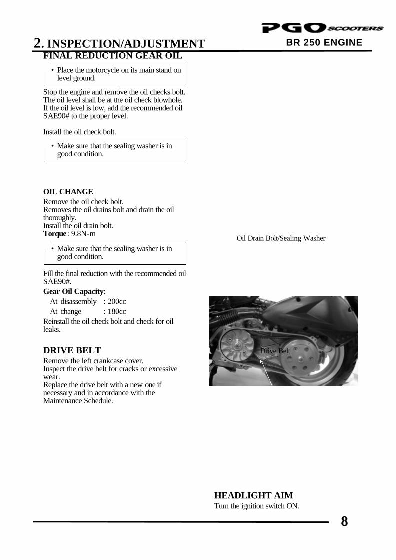
FINAL REDUCTION GEAR OIL Stop the engine and remove the oil checks bolt. The oil level shall be at the oil check blowhole. If the oil level is low, add the recommended oil SAE90# to the proper level. Install the oil check bolt. OIL CHANGE Remove the oil check bolt. Removes the oil drains bolt and drain the oil thoroughly. Install the oil drain bolt. Torque: 9.8N-m Fill the final reduction with the recommended oil SAE90#. Gear Oil Capacity: At disassembly : 200cc At change : 180cc Reinstall the oil check bolt and check for oil leaks. DRIVE BELT Remove the left crankcase cover. Inspect the drive belt for cracks or excessive wear. Replace the drive belt with a new one if necessary and in accordance with the Maintenance Schedule.
HEADLIGHT AIM Turn the ignition switch ON.
Drive Belt
• Place the motorcycle on its main stand on level ground.
*
Oil Drain Bolt/Sealing Washer
• Make sure that the sealing washer is in good condition.
*
• Make sure that the sealing washer is in good condition.
*
2. INSPECTION/ADJUSTMENT
9
BR 250 ENGINE
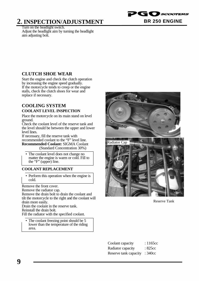
Turn on the headlight switch. Adjust the headlight aim by turning the headlight aim adjusting bolt. CLUTCH SHOE WEAR Start the engine and check the clutch operation by increasing the engine speed gradually. If the motorcycle tends to creep or the engine stalls, check the clutch shoes for wear and replace if necessary. COOLING SYSTEM COOLANT LEVEL INSPECTION Place the motorcycle on its main stand on level ground. Check the coolant level of the reserve tank and the level should be between the upper and lower level lines. If necessary, fill the reserve tank with recommended coolant to the “F” level line. Recommended Coolant: SIGMA Coolant (Standard Concentration 30%) COOLANT REPLACEMENT Remove the front cover. Remove the radiator cap. Remove the drain bolt to drain the coolant and tilt the motorcycle to the right and the coolant will drain more easily. Drain the coolant in the reserve tank. Reinstall the drain bolt. Fill the radiator with the specified coolant.
Coolant capacity : 1165cc Radiator capacity : 825cc Reserve tank capacity : 340cc
• The coolant level does not change no matter the engine is warm or cold. Fill to the “F” (upper) line.
*
• The coolant freezing point should be 5 lower than the temperature of the riding area.
*
• Perform this operation when the engine is cold.
*
Radiator Cap
Reserve Tank
2. INSPECTION/ADJUSTMENT
10
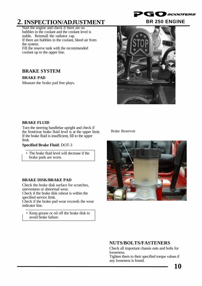
BR 250 ENGINE Start the engine and check if there are no bubbles in the coolant and the coolant level is stable. Reinstall the radiator cap. If there are bubbles in the coolant, bleed air from the system. Fill the reserve tank with the recommended coolant up to the upper line. BRAKE SYSTEM BRAKE PAD Measure the brake pad free plays. BRAKE FLUID Turn the steering handlebar upright and check if the front/rear brake fluid level is at the upper limit. If the brake fluid is insufficient, fill to the upper limit. Specified Brake Fluid: DOT-3 BRAKE DISK/BRAKE PAD Check the brake disk surface for scratches, unevenness or abnormal wear. Check if the brake disk rubout is within the specified service limit. Check if the brake pad wear exceeds the wear indicator line.
NUTS/BOLTS/FASTENERS Check all important chassis nuts and bolts for looseness. Tighten them to their specified torque values if any looseness is found.
• The brake fluid level will decrease if the brake pads are worn.
*
• Keep grease or oil off the brake disk to avoid brake failure.
*
Brake Reservoir
2. INSPECTION/ADJUSTMENT
11
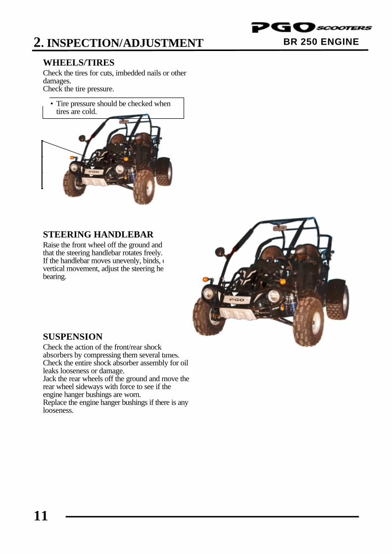
BR 250 ENGINE WHEELS/TIRES Check the tires for cuts, imbedded nails or other damages. Check the tire pressure. Tire Pressure
Off road On road
Front 0.3kg/cm² 0.5kg/cm²
Rear 0.3kg/cm² 0.5kg/cm²
STEERING HANDLEBAR Raise the front wheel off the ground and check that the steering handlebar rotates freely. If the handlebar moves unevenly, binds, or has vertical movement, adjust the steering head bearing. SUSPENSION Check the action of the front/rear shock absorbers by compressing them several times. Check the entire shock absorber assembly for oil leaks looseness or damage. Jack the rear wheels off the ground and move the rear wheel sideways with force to see if the engine hanger bushings are worn. Replace the engine hanger bushings if there is any looseness.
• Tire pressure should be checked when tires are cold.
*
3. LUBRICATION SYSTEM
0
BR & M2 250 ENGINE
3 __________________________________________________________________________________
__________________________________________________________________________________
__________________________________________________________________________________
__________________________________________________________________________________
__________________________________________________________________________________
LUBRICATION SYSTEM
__________________________________________________________________________________
LUBRICATION SYSTEM DIAGRAM ----------------------------------- 3-1
SERVICE INFORMATION ------------------------------------------------- 3-2
TROUBLESHOOTING------------------------------------------------------- 3-2
ENGINE OIL/OIL FILTER -------------------------------------------------- 3-3
OIL PUMP REMOVAL------------------------------------------------------- 3-4
OIL PUMP DISASSEMBLY ------------------------------------------------ 3-4
OIL PUMP INSPECTION --------------------------------------------------- 3-5
OIL PUMP ASSEMBLY ----------------------------------------------------- 3-5
OIL PUMP INSTALLATION ----------------------------------------------- 3-6
3
3. LUBRICATION SYSTEM
1
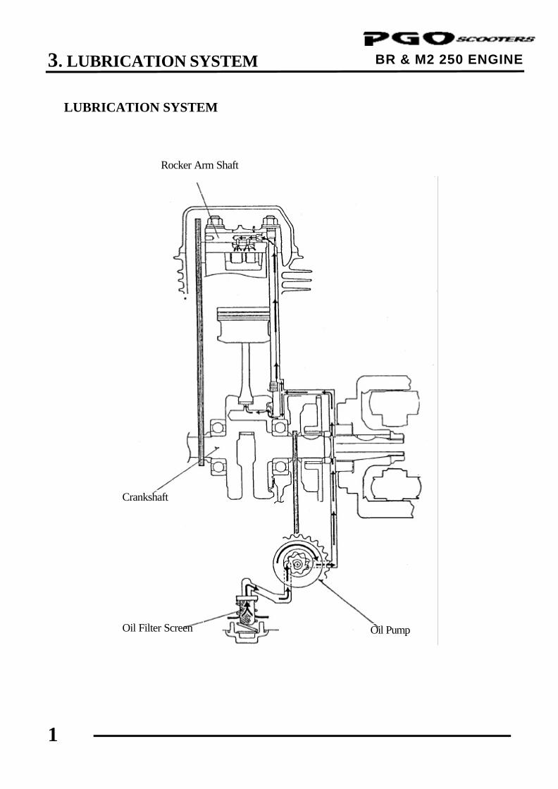
BR & M2 250 ENGINE LUBRICATION SYSTEM
Oil Pump Oil Filter Screen
Crankshaft
Rocker Arm Shaft
3. LUBRICATION SYSTEM
2
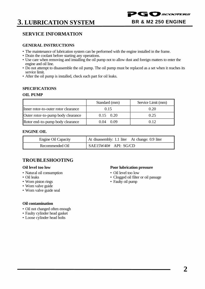
BR & M2 250 ENGINE SERVICE INFORMATION GENERAL INSTRUCTIONS
• The maintenance of lubrication system can be performed with the engine installed in the frame. • Drain the coolant before starting any operations. • Use care when removing and installing the oil pump not to allow dust and foreign matters to enter the
engine and oil line. • Do not attempt to disassemble the oil pump. The oil pump must be replaced as a set when it reaches its
service limit. • After the oil pump is installed, check each part for oil leaks. SPECIFICATIONS
OIL PUMP
Standard (mm) Service Limit (mm) Inner rotor-to-outer rotor clearance 0.15 0.20 Outer rotor-to-pump body clearance 0.15∼0.20 0.25 Rotor end-to-pump body clearance 0.04∼0.09 0.12
ENGINE OIL
Engine Oil Capacity At disassembly: 1.1 liter At change: 0.9 liter Recommended Oil SAE15W40# API: SG/CD
TROUBLESHOOTING
Oil level too low Poor lubrication pressure • Natural oil consumption • Oil level too low • Oil leaks • Clogged oil filter or oil passage • Worn piston rings • Faulty oil pump • Worn valve guide • Worn valve guide seal Oil contamination • Oil not changed often enough • Faulty cylinder head gasket • Loose cylinder head bolts
3. LUBRICATION SYSTEM
3
BR & M2 250 ENGINE
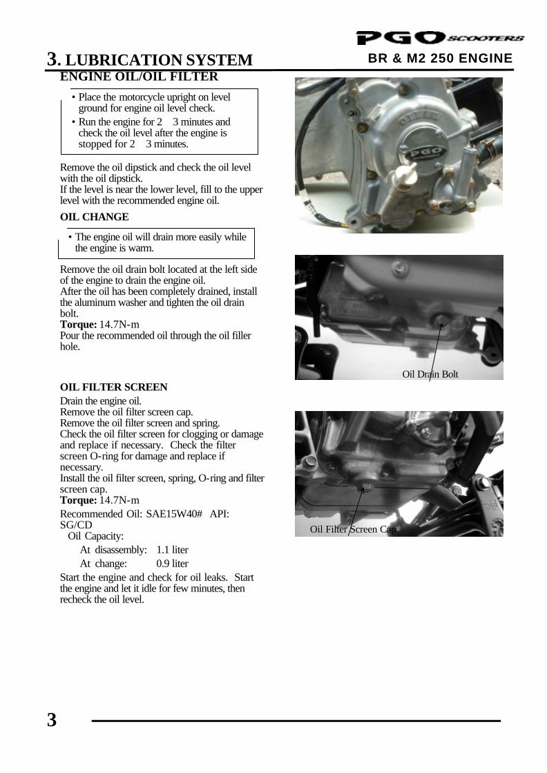
ENGINE OIL/OIL FILTER
Remove the oil dipstick and check the oil level with the oil dipstick. If the level is near the lower level, fill to the upper level with the recommended engine oil.
OIL CHANGE Remove the oil drain bolt located at the left side of the engine to drain the engine oil. After the oil has been completely drained, install the aluminum washer and tighten the oil drain bolt. Torque: 14.7N-m Pour the recommended oil through the oil filler hole. OIL FILTER SCREEN Drain the engine oil. Remove the oil filter screen cap. Remove the oil filter screen and spring. Check the oil filter screen for clogging or damage and replace if necessary. Check the filter screen O-ring for damage and replace if necessary. Install the oil filter screen, spring, O-ring and filter screen cap. Torque: 14.7N-m Recommended Oil: SAE15W40# API: SG/CD Oil Capacity: At disassembly: 1.1 liter At change: 0.9 liter Start the engine and check for oil leaks. Start the engine and let it idle for few minutes, then recheck the oil level.
Oil Dipstick
Oil Drain Bolt
Oil Filter Screen Cap
• Place the motorcycle upright on level ground for engine oil level check.
• Run the engine for 2∼3 minutes and check the oil level after the engine is stopped for 2∼3 minutes.
*
• The engine oil will drain more easily while the engine is warm.
*
3. LUBRICATION SYSTEM
4
BR & M2 250 ENGINE
Circlip
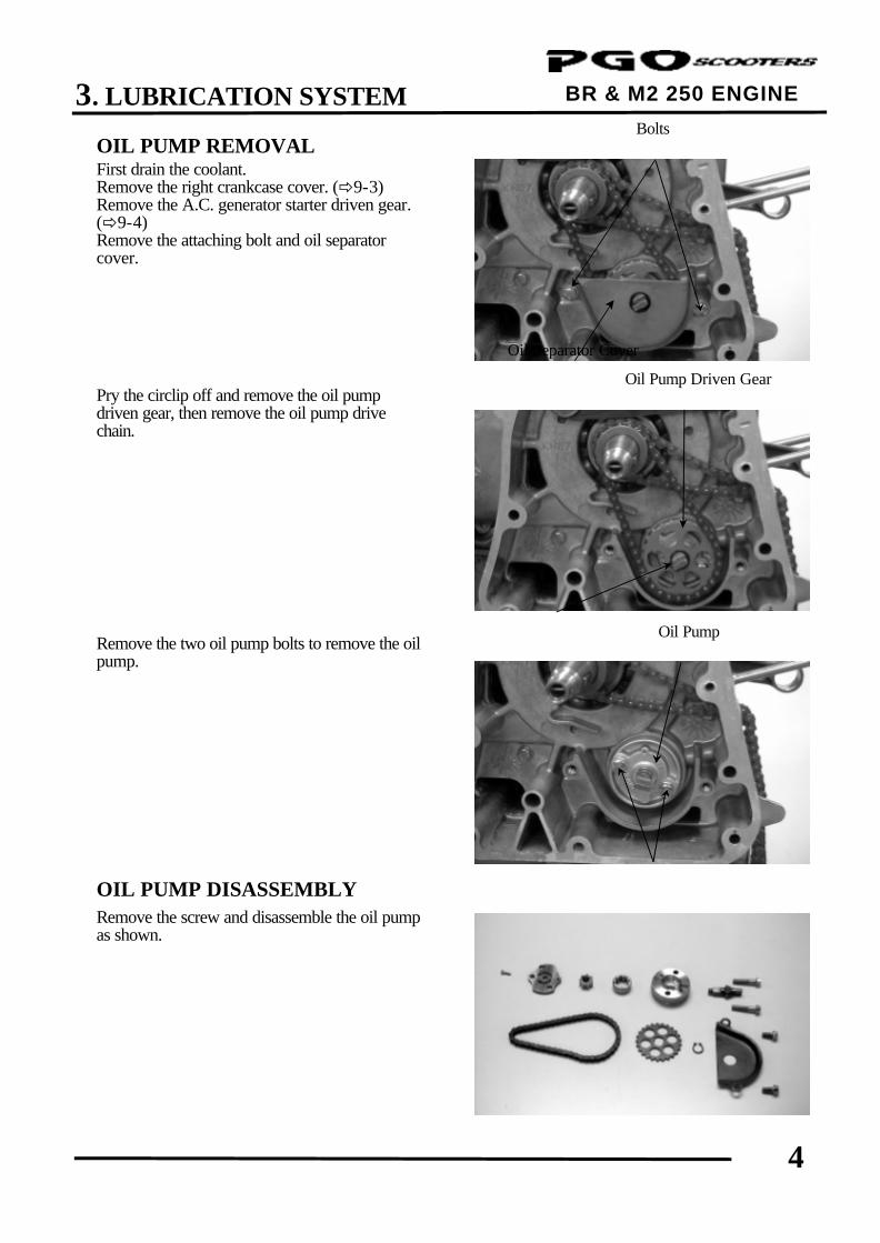
Bolts
Oil Pump Driven Gear
Bolts
OIL PUMP REMOVAL First drain the coolant. Remove the right crankcase cover. (ð9-3) Remove the A.C. generator starter driven gear. (ð9-4) Remove the attaching bolt and oil separator cover. Pry the circlip off and remove the oil pump driven gear, then remove the oil pump drive chain. Remove the two oil pump bolts to remove the oil pump.
OIL PUMP DISASSEMBLY Remove the screw and disassemble the oil pump as shown.
Oil Separator Cover
Oil Pump
3. LUBRICATION SYSTEM
5
BR & M2 250 ENGINE
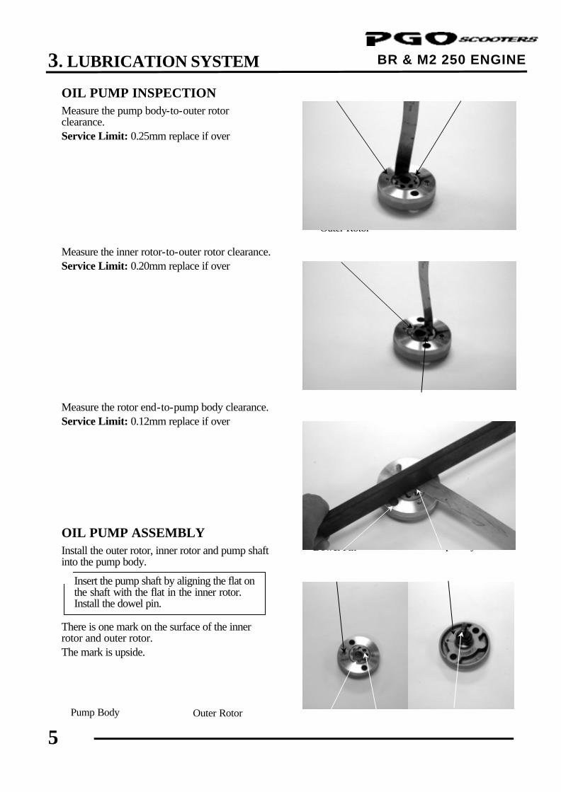
Outer Rotor
Inner Rotor
Outer Rotor
Outer Rotor Inner Rotor
Dowel Pin
Pump Body Rotor End
Pump Body
Pump Shaft
OIL PUMP INSPECTION Measure the pump body-to-outer rotor clearance. Service Limit: 0.25mm replace if over Measure the inner rotor-to-outer rotor clearance. Service Limit: 0.20mm replace if over Measure the rotor end-to-pump body clearance. Service Limit: 0.12mm replace if over
OIL PUMP ASSEMBLY Install the outer rotor, inner rotor and pump shaft into the pump body. There is one mark on the surface of the inner rotor and outer rotor. The mark is upside.
Pump Body
Insert the pump shaft by aligning the flat on the shaft with the flat in the inner rotor. Install the dowel pin.
*
3. LUBRICATION SYSTEM
6
BR & M2 250 ENGINE
Screw
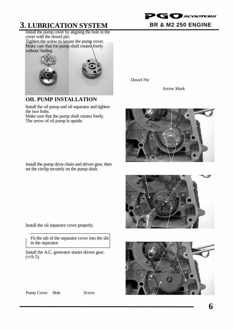
Bolts
Pump Cover
Oil Separator Cover
Pump Driven Gear
Bolts
Install the pump cover by aligning the hole in the cover with the dowel pin. Tighten the screw to secure the pump cover. Make sure that the pump shaft rotates freely without binding. OIL PUMP INSTALLATION Install the oil pump and oil separator and tighten the two bolts. Make sure that the pump shaft rotates freely. The arrow of oil pump is upside. Install the pump drive chain and driven gear, then set the circlip securely on the pump shaft. Install the oil separator cover properly. Install the A.C. generator starter driven gear. (ð9-5)
Circlip
Fit the tab of the separator cover into the slit in the separator.
*
Dowel Pin
Hole
Pump Drive Chain
Arrow Mark
4. CYLINDER HEAD/VALVES
0
BR & M2 250 ENGINE
4. __________________________________________________________________________________
__________________________________________________________________________________
__________________________________________________________________________________
__________________________________________________________________________________
__________________________________________________________________________________
CYLINDER HEAD/VALVES
__________________________________________________________________________________
SCHEMATIC DRAWING --------------------------------------------------- 4- 1
SERVICE INFORMATION ------------------------------------------------- 4- 2
TROUBLESHOOTING------------------------------------------------------- 4- 3
CYLINDER HEAD COVER REMOVAL--------------------------------- 4- 4
CAMSHAFT REMOVAL ---------------------------------------------------- 4- 4
CYLINDER HEAD REMOVAL -------------------------------------------- 4- 6
CYLINDER HEAD DISASSEMBLY -------------------------------------- 4- 7
CYLINDER HEAD ASSEMBLY ------------------------------------------- 4- 8
CYLINDER HEAD INSTALLATION------------------------------------- 4- 9
CAMSHAFT INSTALLATION--------------------------------------------- 4-10
CYLINDER HEAD COVER INSTALLATION-------------------------- 4-11
4
4. CYLINDER HEAD/VALVES
1
BR & M2 250 ENGINE
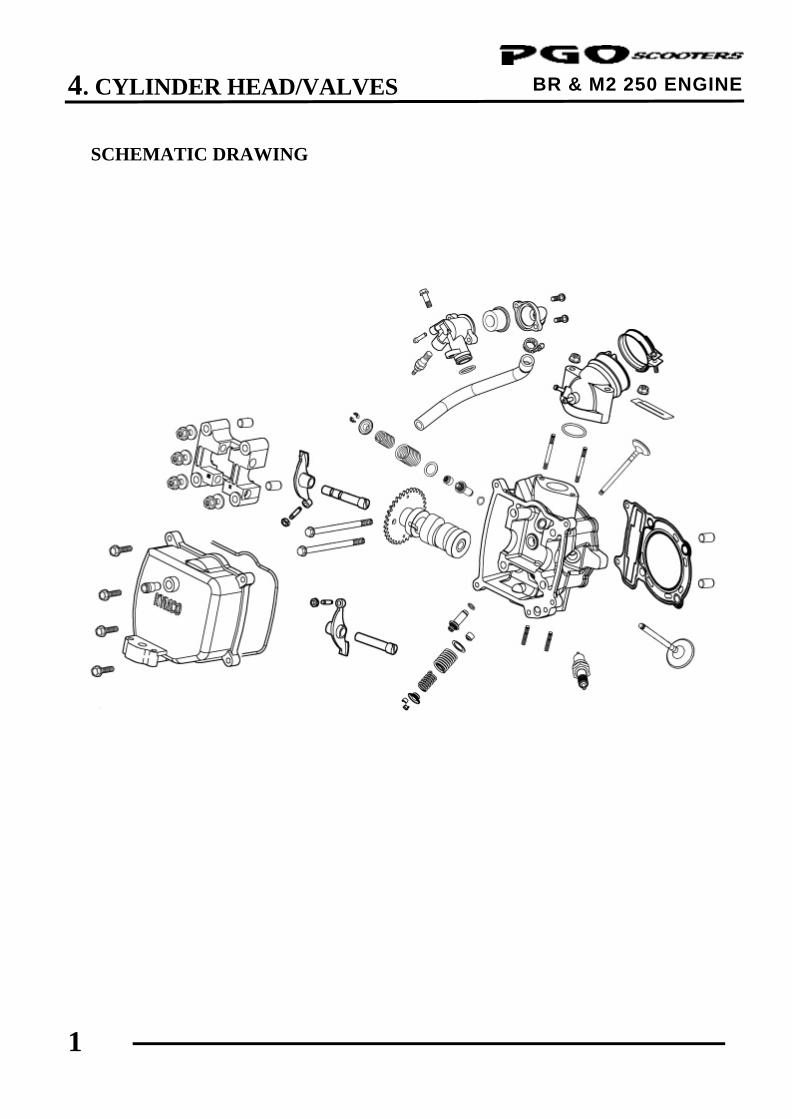
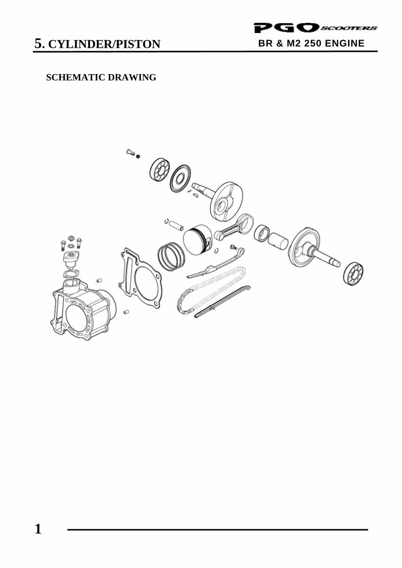
SCHEMATIC DRAWING
4. CYLINDER HEAD/VALVES
2
BR & M2 250 ENGINE SERVICE INFORMATION
GENERAL INSTRUCTIONS
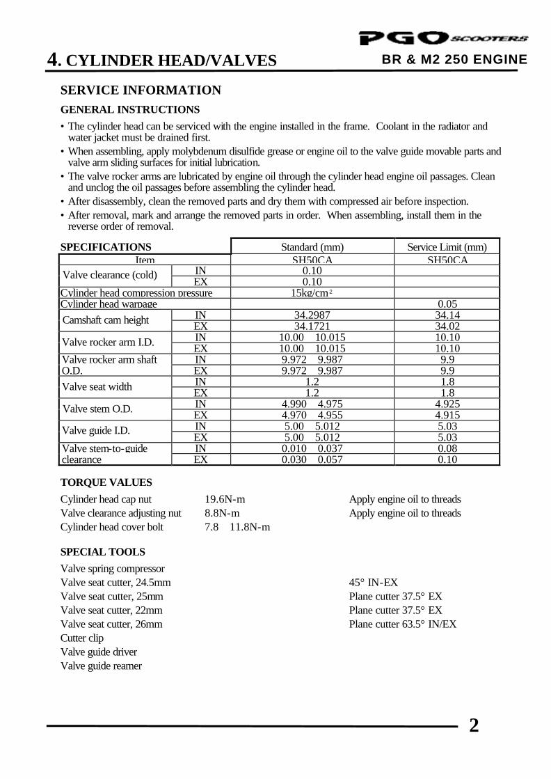
• The cylinder head can be serviced with the engine installed in the frame. Coolant in the radiator and water jacket must be drained first.
• When assembling, apply molybdenum disulfide grease or engine oil to the valve guide movable parts and valve arm sliding surfaces for initial lubrication.
• The valve rocker arms are lubricated by engine oil through the cylinder head engine oil passages. Clean and unclog the oil passages before assembling the cylinder head.
• After disassembly, clean the removed parts and dry them with compressed air before inspection. • After removal, mark and arrange the removed parts in order. When assembling, install them in the
reverse order of removal.
SPECIFICATIONS Standard (mm) Service Limit (mm) Item SH50CA SH50CA IN 0.10
EX 0.10 Cylinder head compression pressure 15kg/cm²
Cylinder head warpage
0.05 IN 34.2987 34.14 EX 34.1721 34.02 IN 10.00∼10.015 10.10 EX 10.00∼10.015 10.10 Valve rocker arm shaft IN 9.972∼9.987 9.9 O.D. EX 9.972∼9.987 9.9 IN 1.2 1.8 EX 1.2 1.8 IN 4.990∼4.975 4.925 EX 4.970∼4.955 4.915 IN 5.00∼5.012 5.03 EX 5.00∼5.012 5.03 Valve stem-to-guide IN 0.010∼0.037 0.08 clearance EX 0.030∼0.057 0.10
TORQUE VALUES
Cylinder head cap nut 19.6N-m Apply engine oil to threads Valve clearance adjusting nut 8.8N-m Apply engine oil to threads Cylinder head cover bolt 7.8∼11.8N-m SPECIAL TOOLS
Valve spring compressor Valve seat cutter, 24.5mm 45° IN-EX Valve seat cutter, 25mm Plane cutter 37.5° EX Valve seat cutter, 22mm Plane cutter 37.5° EX Valve seat cutter, 26mm Plane cutter 63.5° IN/EX Cutter clip Valve guide driver Valve guide reamer
Valve clearance (cold)
Camshaft cam height
Valve rocker arm I.D.
Valve guide I.D.
Valve stem O.D.
Valve seat width
4. CYLINDER HEAD/VALVES
3
BR & M2 250 ENGINE TROUBLESHOOTING • The poor cylinder head operation can be diagnosed by a compression test or by tracing engine top-end
noises. Poor performance at idle speed White smoke from exhaust muffler • Compression too low • Worn valve stem or valve guide • Damaged valve stem oil seal Compression too low • Incorrect valve clearance adjustment Abnormal noise • Burned or bend valves • Incorrect valve clearance adjustment • Incorrect valve timing • Sticking valve or broken valve spring • Broken valve spring • Damaged or worn camshaft • Poor valve and seat contact • Worn cam chain tensioner • Leaking cylinder head gasket • Worn camshaft and rocker arm • Warped or cracked cylinder head • Poorly installed spark plug Compression too high • Excessive carbon build-up in combustion chamber
4. CYLINDER HEAD/VALVES
4
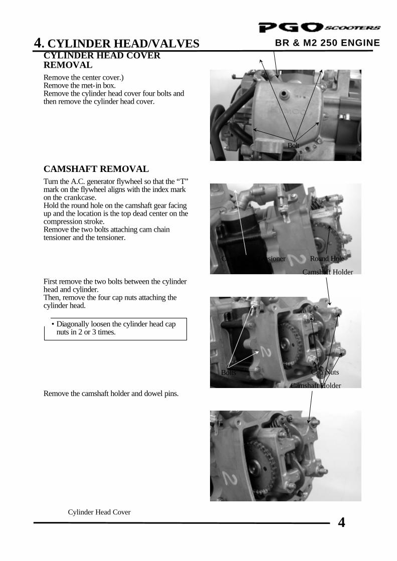
BR & M2 250 ENGINE CYLINDER HEAD COVER REMOVAL Remove the center cover.) Remove the met-in box. Remove the cylinder head cover four bolts and then remove the cylinder head cover.
CAMSHAFT REMOVAL Turn the A.C. generator flywheel so that the “T” mark on the flywheel aligns with the index mark on the crankcase. Hold the round hole on the camshaft gear facing up and the location is the top dead center on the compression stroke. Remove the two bolts attaching cam chain tensioner and the tensioner. First remove the two bolts between the cylinder head and cylinder. Then, remove the four cap nuts attaching the cylinder head. Remove the camshaft holder and dowel pins.
Cylinder Head Cover
Bolt
Cam Chain Tensioner Round Hole
Camshaft Holder
Bolts
• Diagonally loosen the cylinder head cap nuts in 2 or 3 times.
*
Camshaft Holder
Cap Nuts
4. CYLINDER HEAD/VALVES
5
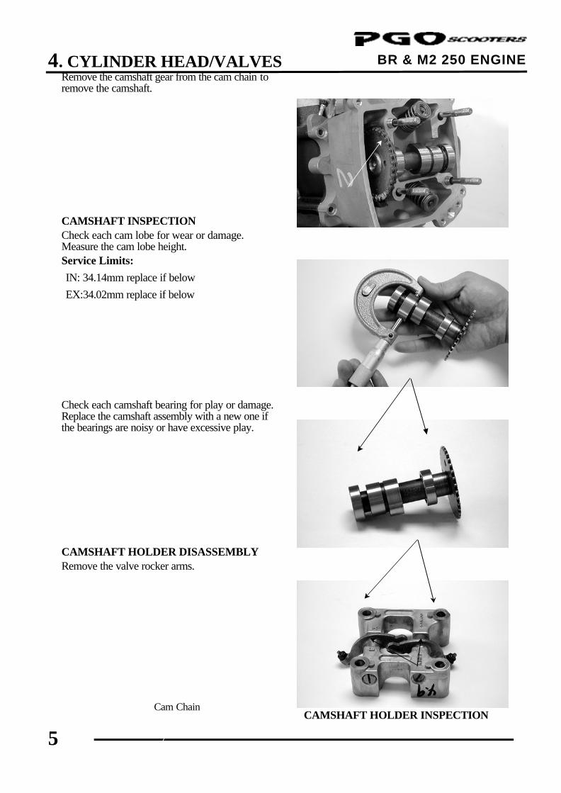
BR & M2 250 ENGINE Remove the camshaft gear from the cam chain to remove the camshaft. CAMSHAFT INSPECTION Check each cam lobe for wear or damage. Measure the cam lobe height. Service Limits:
IN: 34.14mm replace if below
EX:34.02mm replace if below
Check each camshaft bearing for play or damage. Replace the camshaft assembly with a new one if the bearings are noisy or have excessive play. CAMSHAFT HOLDER DISASSEMBLY Remove the valve rocker arms.
CAMSHAFT HOLDER INSPECTION
Cam Chain
Camshaft Gear
Camshaft Bearings
Valve Rocker Arms
Rocker Arm Shafts
4. CYLINDER HEAD/VALVES
6
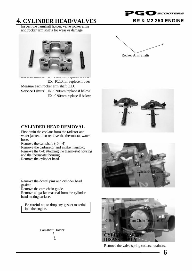
BR & M2 250 ENGINE Inspect the camshaft holder, valve rocker arms and rocker arm shafts for wear or damage. Measure the I.D. of each valve rocker arm. Service Limits: IN: 10.10mm replace if over
EX: 10.10mm replace if over Measure each rocker arm shaft O.D. Service Limits: IN: 9.90mm replace if below
EX: 9.90mm replace if below
CYLINDER HEAD REMOVAL First drain the coolant from the radiator and water jacket, then remove the thermostat water hose. Remove the camshaft. (ð4-4) Remove the carburetor and intake manifold. Remove the bolt attaching the thermostat housing and the thermostat housing. Remove the cylinder head. Remove the dowel pins and cylinder head gasket. Remove the cam chain guide. Remove all gasket material from the cylinder head mating surface.
CYLINDER HEAD DISASSEMBLY Remove the valve spring cotters, retainers,
Bolt
Cam Chain Tensioner Slipper
Camshaft Holder
If the valve rocker arm contact surface is worn, check each cam lobe for wear or damage.
*
Be careful not to drop any gasket material into the engine.
*
Rocker Arm Shafts
Cylinder
Cylinder Head Gasket
4. CYLINDER HEAD/VALVES
7
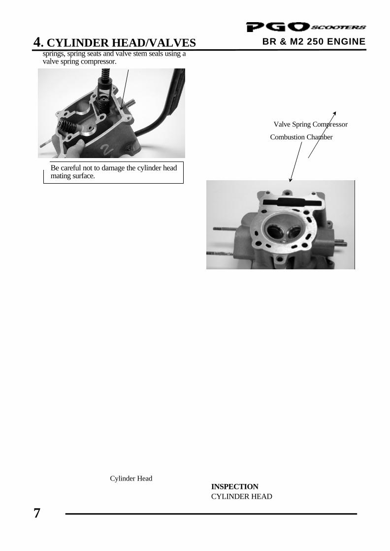
BR & M2 250 ENGINE springs, spring seats and valve stem seals using a valve spring compressor. Remove carbon deposits from the exhaust port and combustion chamber.
INSPECTION CYLINDER HEAD
Valve Spring Compressor
Cylinder Head
• Be sure to compress the valve springs with a valve spring compressor.
• Mark all disassembled parts to ensure correct reassembly.
*
Be careful not to damage the cylinder head mating surface.
*
Combustion Chamber
4. CYLINDER HEAD/VALVES
8
BR & M2 250 ENGINE
Be careful not to damage the valves. *
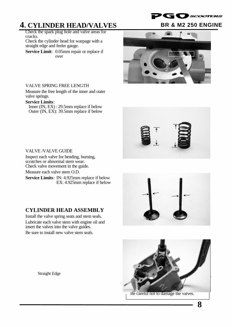
Check the spark plug hole and valve areas for cracks. Check the cylinder head for warpage with a straight edge and feeler gauge. Service Limit: 0.05mm repair or replace if
over VALVE SPRING FREE LENGTH Measure the free length of the inner and outer valve springs. Service Limits:
Inner (IN, EX) : 29.5mm replace if below Outer (IN, EX): 39.5mm replace if below
VALVE /VALVE GUIDE Inspect each valve for bending, burning, scratches or abnormal stem wear. Check valve movement in the guide. Measure each valve stem O.D. Service Limits: IN: 4.925mm replace if below EX: 4.925mm replace if below CYLINDER HEAD ASSEMBLY Install the valve spring seats and stem seals. Lubricate each valve stem with engine oil and insert the valves into the valve guides. Be sure to install new valve stem seals.
Tap the valve stems gently with a plastic hammer to firmly seat the cotters.
Straight Edge
Valve Spring Compressor
Feeler Gauge
4. CYLINDER HEAD/VALVES
9
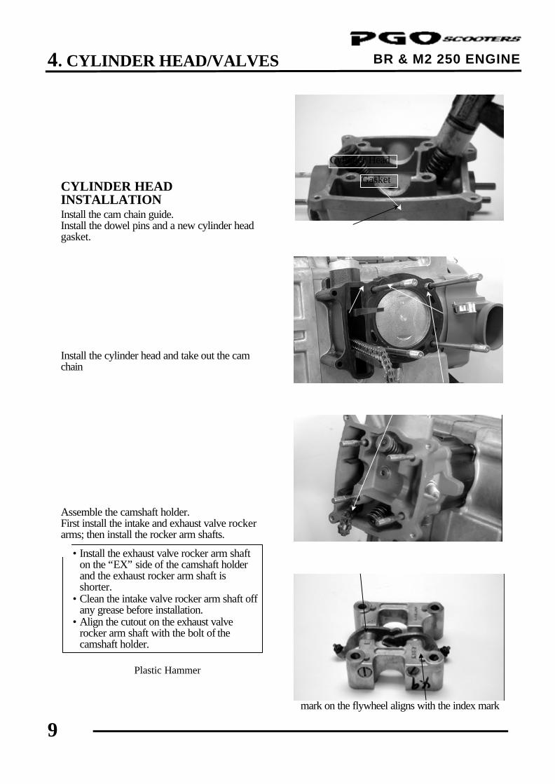
BR & M2 250 ENGINE CYLINDER HEAD INSTALLATION Install the cam chain guide. Install the dowel pins and a new cylinder head gasket. Install the cylinder head and take out the cam chain Assemble the camshaft holder. First install the intake and exhaust valve rocker arms; then install the rocker arm shafts.
CAMSHAFT INSTALLATION Turn the A.C. generator flywheel so that the “T” mark on the flywheel aligns with the index mark
Gasket
Cam Chain Guide
Valve Rocker Arms
Plastic Hammer
Cam Chain
Cylinder Head
Camshaft Holder
Dowel Pins
• Install the exhaust valve rocker arm shaft on the “EX” side of the camshaft holder and the exhaust rocker arm shaft is shorter.
• Clean the intake valve rocker arm shaft off any grease before installation.
• Align the cutout on the exhaust valve rocker arm shaft with the bolt of the camshaft holder.
*
4. CYLINDER HEAD/VALVES
10
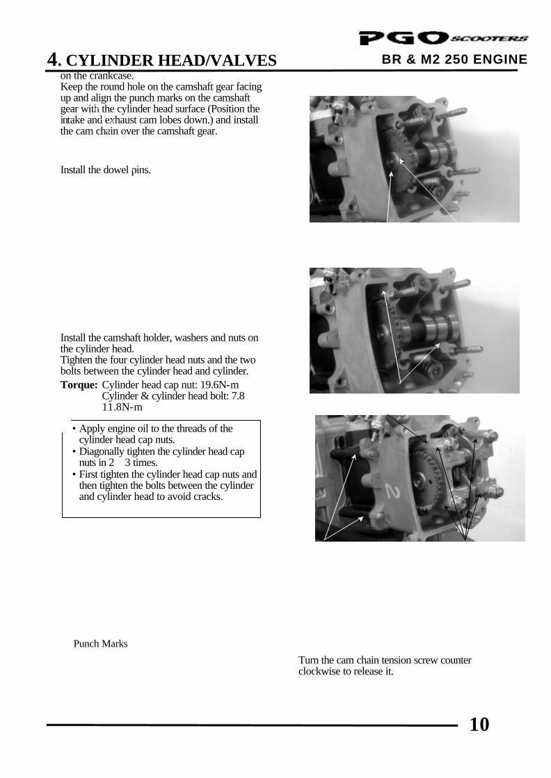
BR & M2 250 ENGINE on the crankcase. Keep the round hole on the camshaft gear facing up and align the punch marks on the camshaft gear with the cylinder head surface (Position the intake and exhaust cam lobes down.) and install the cam chain over the camshaft gear. Install the dowel pins. Install the camshaft holder, washers and nuts on the cylinder head. Tighten the four cylinder head nuts and the two bolts between the cylinder head and cylinder. Torque: Cylinder head cap nut: 19.6N-m
Cylinder & cylinder head bolt: 7.8∼11.8N-m
Turn the cam chain tension screw counter clockwise to release it.
Punch Marks
• Apply engine oil to the threads of the cylinder head cap nuts.
• Diagonally tighten the cylinder head cap nuts in 2∼3 times.
• First tighten the cylinder head cap nuts and then tighten the bolts between the cylinder and cylinder head to avoid cracks.
*
Cam Chain Round Hole
Dowel Pins
Washer
Nut Bolts
4. CYLINDER HEAD/VALVES
11
BR & M2 250 ENGINE
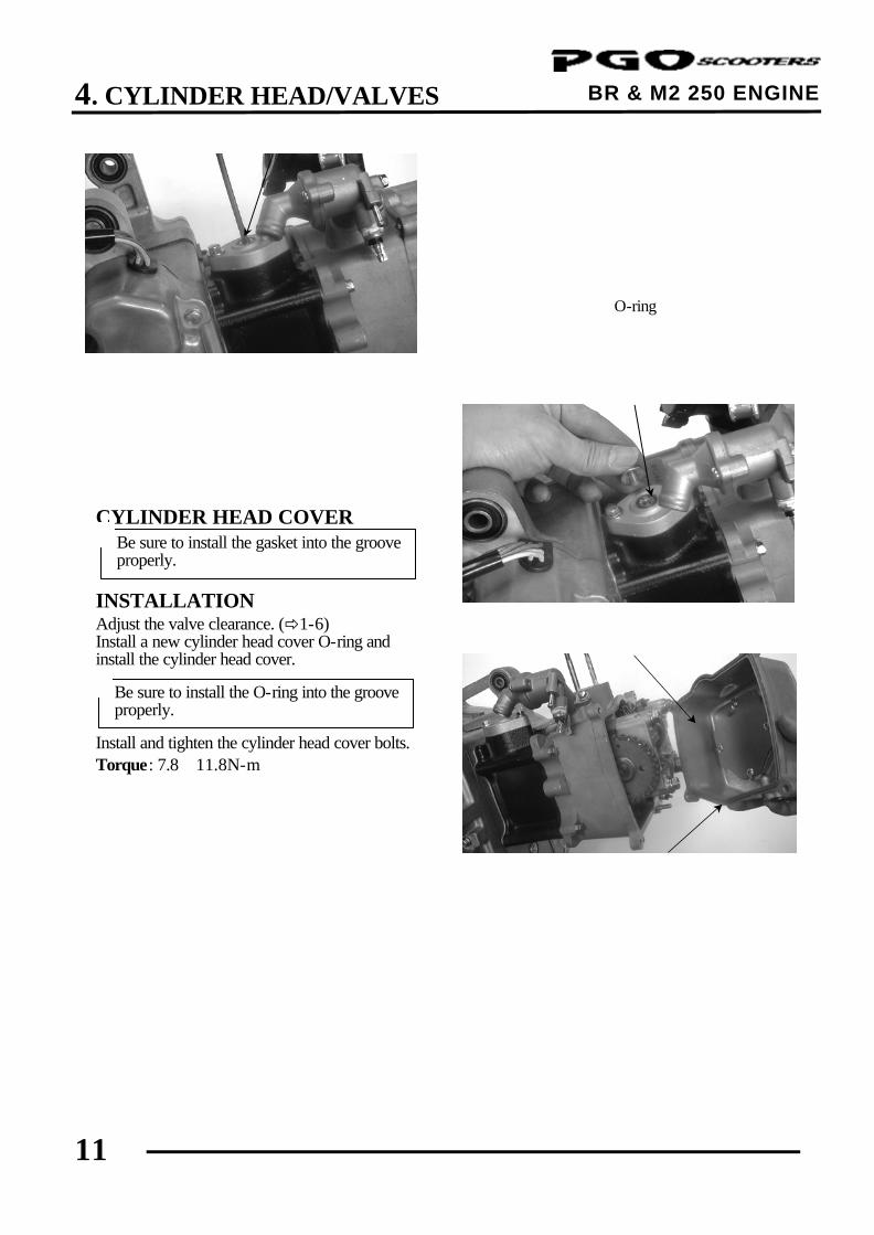
Be sure to install the gasket into the groove properly.
Apply engine oil to a new O-ring and install it. Tighten the cam chain tension cap screw. CYLINDER HEAD COVER
INSTALLATION Adjust the valve clearance. (ð1-6) Install a new cylinder head cover O-ring and install the cylinder head cover.
Install and tighten the cylinder head cover bolts. Torque: 7.8∼11.8N-m
O-ring
Cylinder Head Cover
O-ring
Be sure to install the O-ring into the groove properly.
*
*
5. CYLINDER/PISTON
0
BR & M2 250 ENGINE
5 __________________________________________________________________________________
__________________________________________________________________________________
__________________________________________________________________________________
__________________________________________________________________________________
__________________________________________________________________________________
CYLINDER/PISTON
__________________________________________________________________________________
SCHEMATIC DRAWING --------------------------------------------------- 5-1
SERVICE INFORMATION ------------------------------------------------- 5-2
TROUBLESHOOTING------------------------------------------------------- 5-2
CYLINDER REMOVAL------------------------------------------------------ 5-3
PISTON REMOVAL---------------------------------------------------------- 5-3
PISTON INSTALLATION--------------------------------------------------- 5-7
CYLINDER INSTALLATION ---------------------------------------------- 5-7
5
5. CYLINDER/PISTON
1
BR & M2 250 ENGINE SCHEMATIC DRAWING
5. CYLINDER/PISTON
2
BR & M2 250 ENGINE SERVICE INFORMATION
GENERAL INSTRUCTIONS
• The cylinder and piston can be serviced with the engine installed in the frame. • When installing the cylinder, use a new cylinder gasket and make sure that the dowel pins are correctly
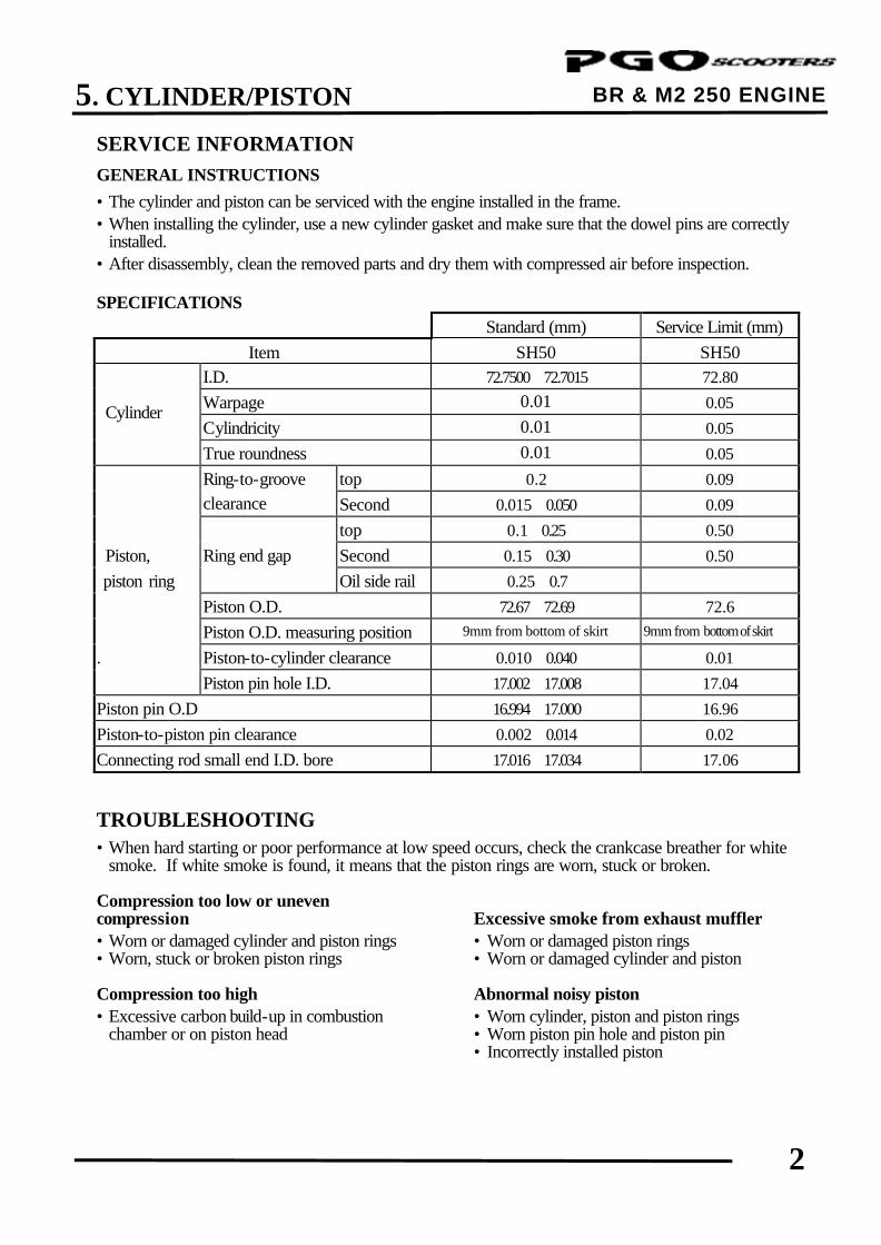
installed. • After disassembly, clean the removed parts and dry them with compressed air before inspection. SPECIFICATIONS
Standard (mm) Service Limit (mm) Item SH50 SH50 I.D. 72.7500∼72.7015 72.80 Warpage 0.01 0.05 Cylindricity 0.01 0.05 True roundness 0.01 0.05 Ring-to-groove top 0.2 0.09 clearance Second 0.015∼0.050 0.09 top 0.1∼0.25 0.50 Piston, Ring end gap Second 0.15∼0.30 0.50 piston ring Oil side rail 0.25∼0.7
Piston O.D. 72.67∼72.69 72.6 Piston O.D. measuring position 9mm from bottom of skirt 9mm from bottom of skirt
. Piston-to-cylinder clearance 0.010∼0.040 0.01 Piston pin hole I.D. 17.002∼17.008 17.04 Piston pin O.D 16.994∼17.000 16.96 Piston-to-piston pin clearance 0.002∼0.014 0.02 Connecting rod small end I.D. bore 17.016∼17.034 17.06
TROUBLESHOOTING • When hard starting or poor performance at low speed occurs, check the crankcase breather for white
smoke. If white smoke is found, it means that the piston rings are worn, stuck or broken. Compression too low or uneven compression Excessive smoke from exhaust muffler • Worn or damaged cylinder and piston rings • Worn or damaged piston rings • Worn, stuck or broken piston rings • Worn or damaged cylinder and piston Compression too high Abnormal noisy piston • Excessive carbon build-up in combustion • Worn cylinder, piston and piston rings chamber or on piston head • Worn piston pin hole and piston pin • Incorrectly installed piston
Cylinder
5. CYLINDER/PISTON
3
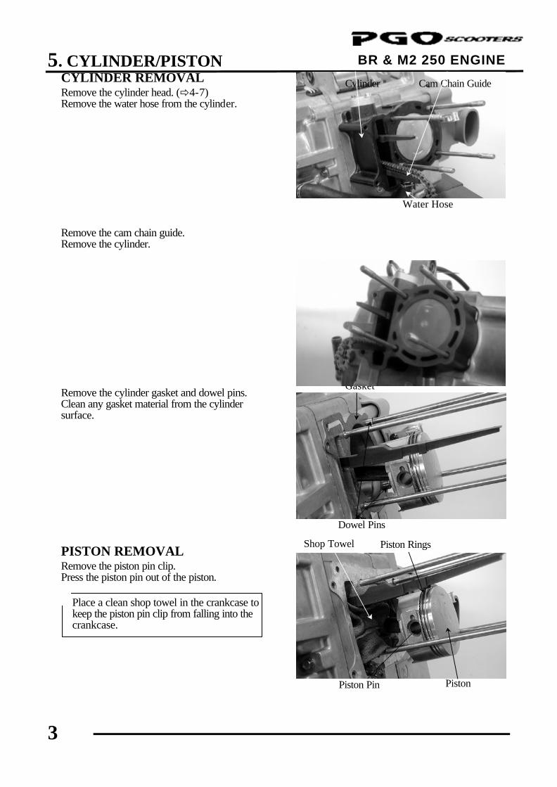
BR & M2 250 ENGINE CYLINDER REMOVAL Remove the cylinder head. (ð4-7) Remove the water hose from the cylinder. Remove the cam chain guide. Remove the cylinder. Remove the cylinder gasket and dowel pins. Clean any gasket material from the cylinder surface. PISTON REMOVAL Remove the piston pin clip. Press the piston pin out of the piston.
Dowel Pins
Gasket
Place a clean shop towel in the crankcase to keep the piston pin clip from falling into the crankcase.
*
Water Hose
Cam Chain Guide Cylinder
Shop Towel
Piston Pin Piston
Piston Rings
5. CYLINDER/PISTON
4
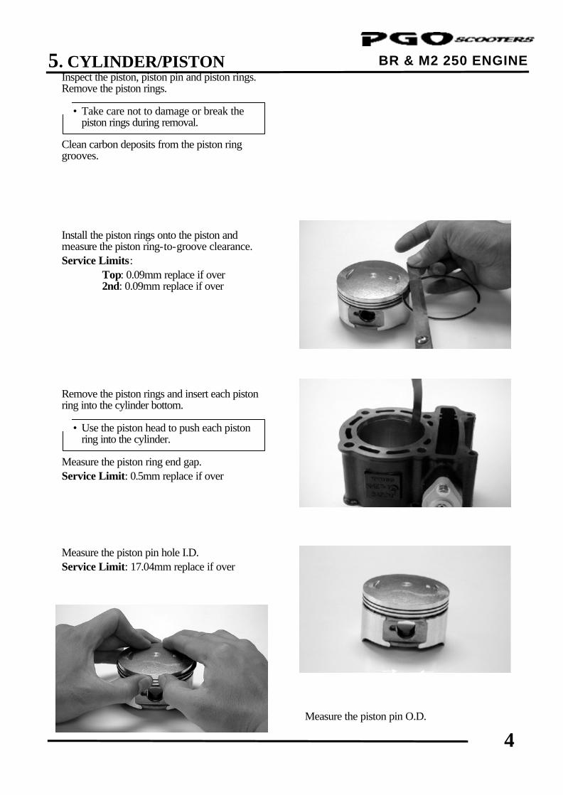
BR & M2 250 ENGINE Inspect the piston, piston pin and piston rings. Remove the piston rings. Clean carbon deposits from the piston ring grooves. Install the piston rings onto the piston and measure the piston ring-to-groove clearance. Service Limits:
Top: 0.09mm replace if over 2nd: 0.09mm replace if over
Remove the piston rings and insert each piston ring into the cylinder bottom. Measure the piston ring end gap. Service Limit: 0.5mm replace if over Measure the piston pin hole I.D. Service Limit: 17.04mm replace if over
Measure the piston pin O.D.
• Take care not to damage or break the piston rings during removal.
*
• Use the piston head to push each piston ring into the cylinder.
*
5. CYLINDER/PISTON
5
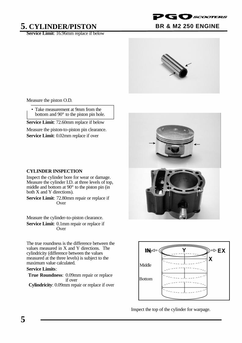
BR & M2 250 ENGINE
Service Limit: 16.96mm replace if below Measure the piston O.D. Service Limit: 72.60mm replace if below
Measure the piston-to-piston pin clearance. Service Limit: 0.02mm replace if over CYLINDER INSPECTION Inspect the cylinder bore for wear or damage. Measure the cylinder I.D. at three levels of top, middle and bottom at 90° to the piston pin (in both X and Y directions). Service Limit: 72.80mm repair or replace if Over
Measure the cylinder-to-piston clearance. Service Limit: 0.1mm repair or replace if Over The true roundness is the difference between the values measured in X and Y directions. The cylindricity (difference between the values measured at the three levels) is subject to the maximum value calculated. Service Limits: True Roundness: 0.09mm repair or replace if over Cylindricity: 0.09mm repair or replace if over
Inspect the top of the cylinder for warpage.
• Take measurement at 9mm from the bottom and 90° to the piston pin hole.
*
Middle
Bottom
Top
5. CYLINDER/PISTON
6
BR & M2 250 ENGINE
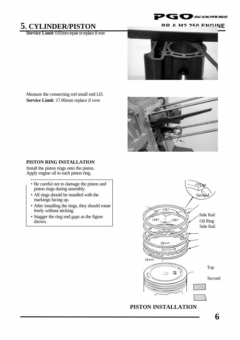
Service Limit: 0.05mm repair or replace if over Measure the connecting rod small end I.D. Service Limit: 17.06mm replace if over PISTON RING INSTALLATION Install the piston rings onto the piston. Apply engine oil to each piston ring.
PISTON INSTALLATION
Second
Side Rail
Top • Be careful not to damage the piston and piston rings during assembly.
• All rings should be installed with the markings facing up.
• After installing the rings, they should rotate freely without sticking.
• Stagger the ring end gaps as the figure shown.
*
Second
Top
Side Rail Oil Ring
5. CYLINDER/PISTON
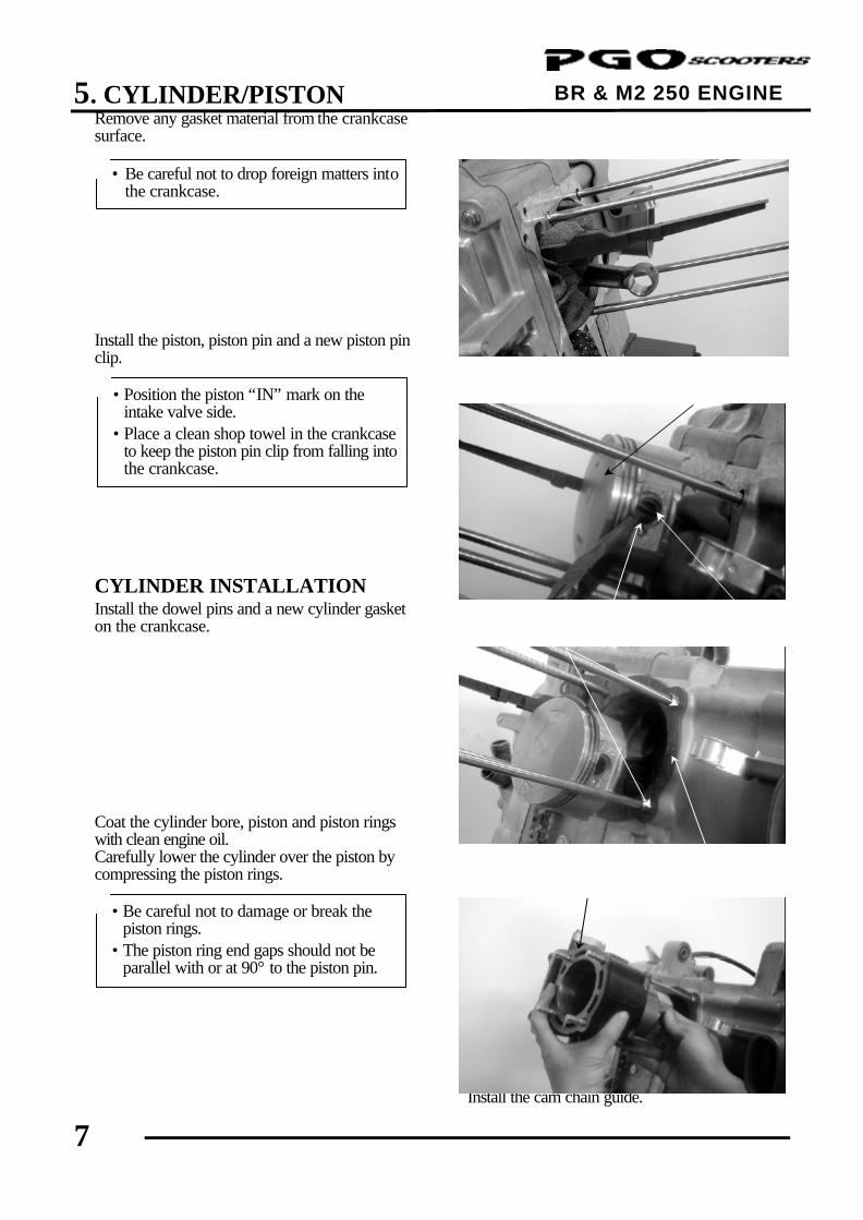
7
BR & M2 250 ENGINE Remove any gasket material from the crankcase surface. Install the piston, piston pin and a new piston pin clip. CYLINDER INSTALLATION Install the dowel pins and a new cylinder gasket on the crankcase. Coat the cylinder bore, piston and piston rings with clean engine oil. Carefully lower the cylinder over the piston by compressing the piston rings.
Install the cam chain guide.
Gasket
Cylinder
Dowel Pin
• Be careful not to drop foreign matters into the crankcase.
*
• Position the piston “IN” mark on the intake valve side.
• Place a clean shop towel in the crankcase to keep the piston pin clip from falling into the crankcase.
*
• Be careful not to damage or break the piston rings.
• The piston ring end gaps should not be parallel with or at 90° to the piston pin.
*
Piston
Piston Pin Clip Piston Pin
5. CYLINDER/PISTON
8
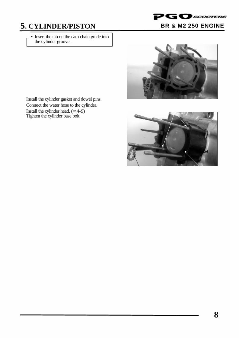
BR & M2 250 ENGINE Install the cylinder gasket and dowel pins. Connect the water hose to the cylinder. Install the cylinder head. (ð4-9) Tighten the cylinder base bolt.
• Insert the tab on the cam chain guide into the cylinder groove.
*
Cam Chain Guide
Gasket
Dowel Pin
6. DRIVE AND DRIVEN PULLEYS/ KICK STARTER
0
BR & M2 250 ENGINE
6 __________________________________________________________________________________
__________________________________________________________________________________
__________________________________________________________________________________
__________________________________________________________________________________
__________________________________________________________________________________
DRIVE AND DRIVEN PULLEYS/ KICK STARTER
__________________________________________________________________________________
SCHEMATIC DRAWING --------------------------------------------------- 6- 1
SERVICE INFORMATION ------------------------------------------------- 6- 2
TROUBLESHOOTING------------------------------------------------------- 6- 2
LEFT CRANKCASE COVER ---------------------------------------------- 6- 3
DRIVE PULLEY --------------------------------------------------------------- 6- 4
CLUTCH/DRIVEN PULLEY------------------------------------------------ 6- 8
6
6. DRIVE AND DRIVEN PULLEYS/ KICK STARTER
1
BR & M2 250 ENGINE
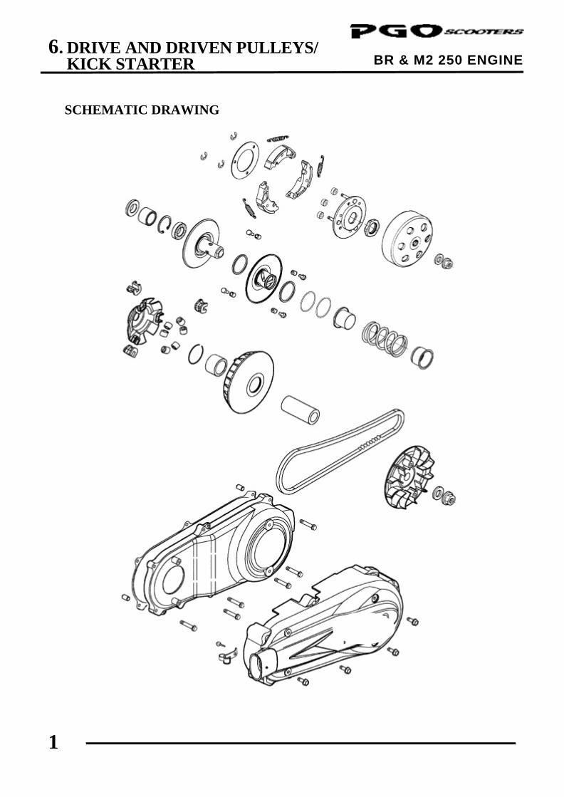
SCHEMATIC DRAWING
6. DRIVE AND DRIVEN PULLEYS/ KICK STARTER
2
BR & M2 250 ENGINE
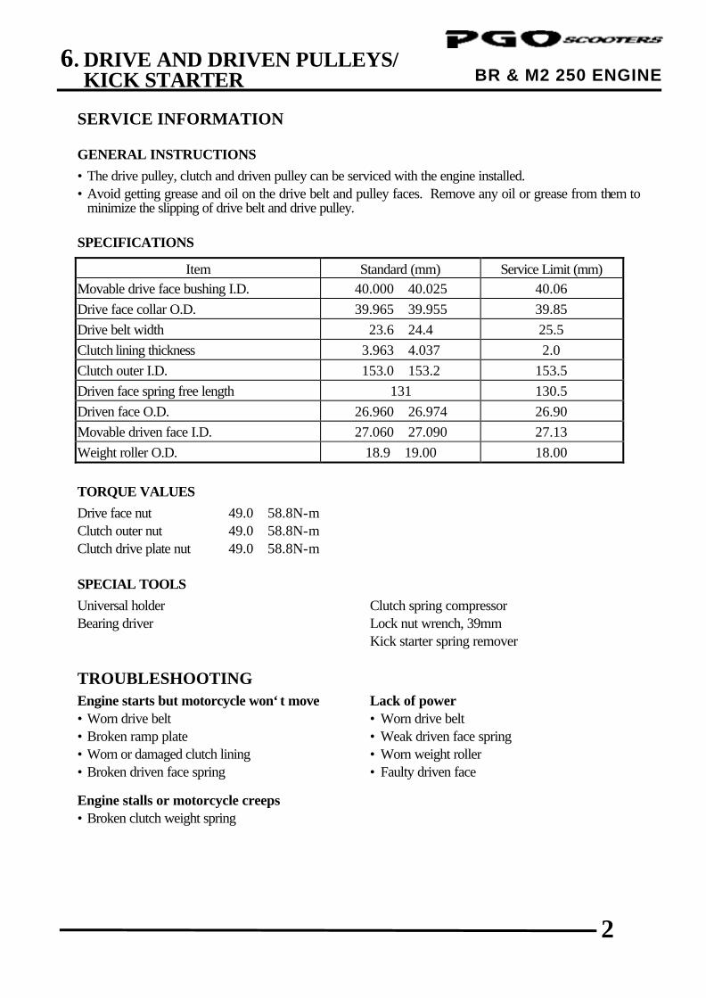
SERVICE INFORMATION GENERAL INSTRUCTIONS
• The drive pulley, clutch and driven pulley can be serviced with the engine installed. • Avoid getting grease and oil on the drive belt and pulley faces. Remove any oil or grease from them to
minimize the slipping of drive belt and drive pulley. SPECIFICATIONS
Item Standard (mm) Service Limit (mm) Movable drive face bushing I.D. 40.000∼40.025 40.06 Drive face collar O.D. 39.965∼39.955 39.85 Drive belt width 23.6∼24.4 25.5 Clutch lining thickness 3.963∼4.037 2.0 Clutch outer I.D. 153.0∼153.2 153.5 Driven face spring free length 131 130.5 Driven face O.D. 26.960∼26.974 26.90 Movable driven face I.D. 27.060∼27.090 27.13 Weight roller O.D. 18.9∼19.00 18.00
TORQUE VALUES
Drive face nut 49.0∼58.8N-m Clutch outer nut 49.0∼58.8N-m Clutch drive plate nut 49.0∼58.8N-m
SPECIAL TOOLS
Universal holder Clutch spring compressor Bearing driver Lock nut wrench, 39mm Kick starter spring remover
TROUBLESHOOTING Engine starts but motorcycle won‘t move Lack of power • Worn drive belt • Worn drive belt • Broken ramp plate • Weak driven face spring • Worn or damaged clutch lining • Worn weight roller • Broken driven face spring • Faulty driven face Engine stalls or motorcycle creeps • Broken clutch weight spring
6. DRIVE AND DRIVEN PULLEYS/ KICK STARTER
3
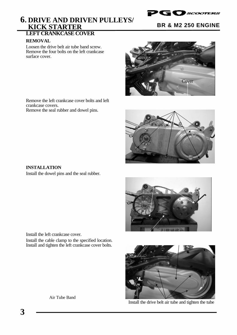
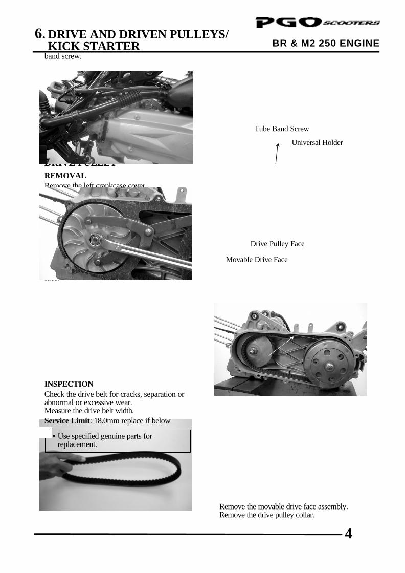
BR & M2 250 ENGINE LEFT CRANKCASE COVER REMOVAL Loosen the drive belt air tube band screw. Remove the four bolts on the left crankcase surface cover. Remove the left crankcase cover bolts and left crankcase covers. Remove the seal rubber and dowel pins. INSTALLATION Install the dowel pins and the seal rubber. Install the left crankcase cover. Install the cable clamp to the specified location. Install and tighten the left crankcase cover bolts.
Install the drive belt air tube and tighten the tube
Left Crankcase Cover
Air Tube Band
Bolts
Dowel Pins
Seal Rubber
Left Crankcase Cover
Bolts
Cover
6. DRIVE AND DRIVEN PULLEYS/ KICK STARTER
4
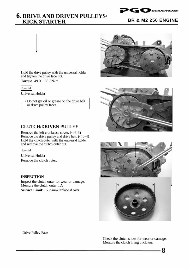
BR & M2 250 ENGINE band screw. DRIVE PULLEY REMOVAL Remove the left crankcase cover. Hold the drive pulley using an universal holder and remove the drive face nut and washer. Remove the drive pulley face. Universal Holder Remove the drive belt from the movable drive face. INSPECTION Check the drive belt for cracks, separation or abnormal or excessive wear. Measure the drive belt width. Service Limit: 18.0mm replace if below
Remove the movable drive face assembly. Remove the drive pulley collar.
Drive Pulley Face
Universal Holder
• Use specified genuine parts for replacement.
*
Movable Drive Face
Drive Belt
Tube Band Screw
Special
6. DRIVE AND DRIVEN PULLEYS/ KICK STARTER
5
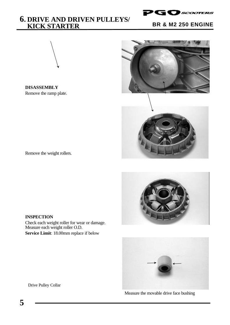
BR & M2 250 ENGINE DISASSEMBLY Remove the ramp plate. Remove the weight rollers. INSPECTION Check each weight roller for wear or damage. Measure each weight roller O.D. Service Limit: 18.00mm replace if below
Measure the movable drive face bushing
Drive Pulley Collar
Ramp Plate
Weight Roller
Movable Drive Face Assembly
6. DRIVE AND DRIVEN PULLEYS/ KICK STARTER
6
BR & M2 250 ENGINE
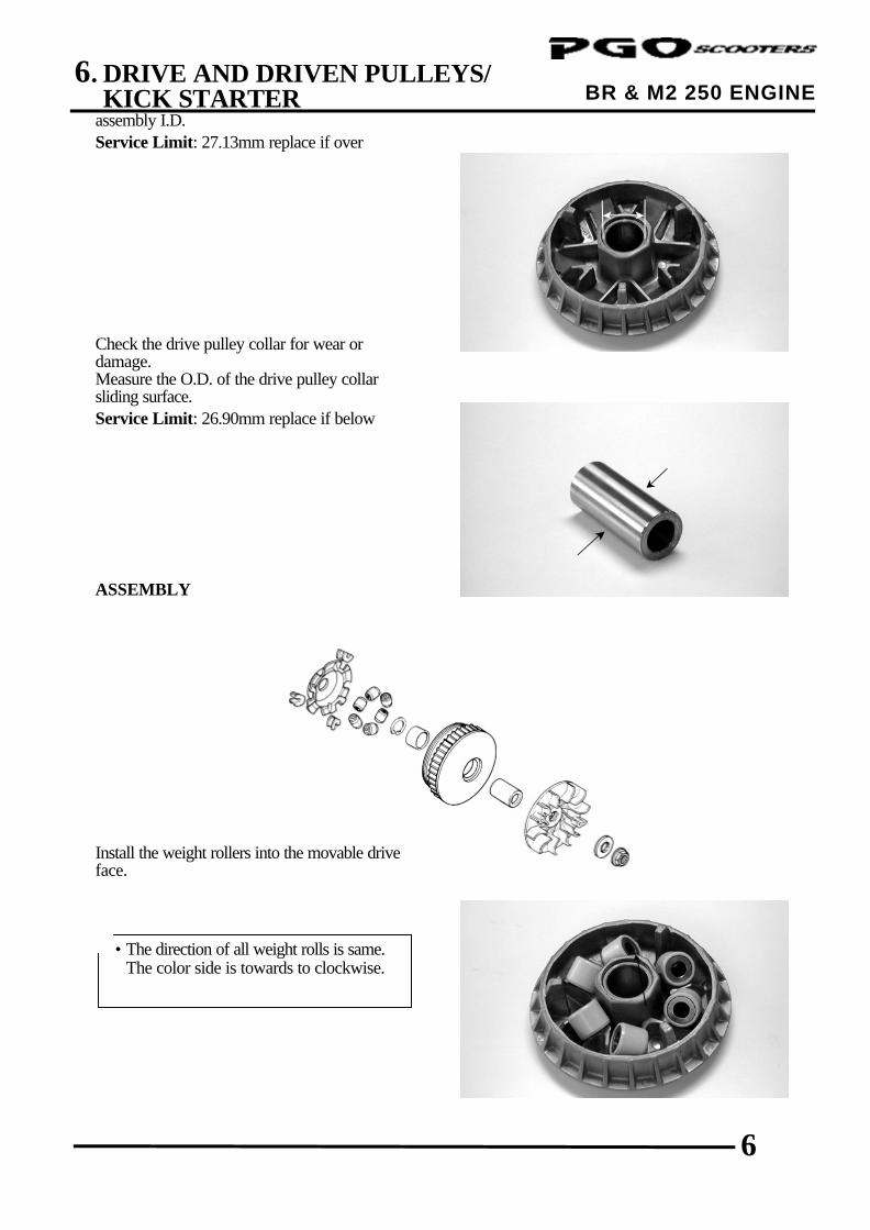
assembly I.D. Service Limit: 27.13mm replace if over Check the drive pulley collar for wear or damage. Measure the O.D. of the drive pulley collar sliding surface. Service Limit: 26.90mm replace if below ASSEMBLY
Install the weight rollers into the movable drive face.
Install the ramp plate.
Weight Roller
• The direction of all weight rolls is same. The color side is towards to clockwise.
*
6. DRIVE AND DRIVEN PULLEYS/ KICK STARTER
7
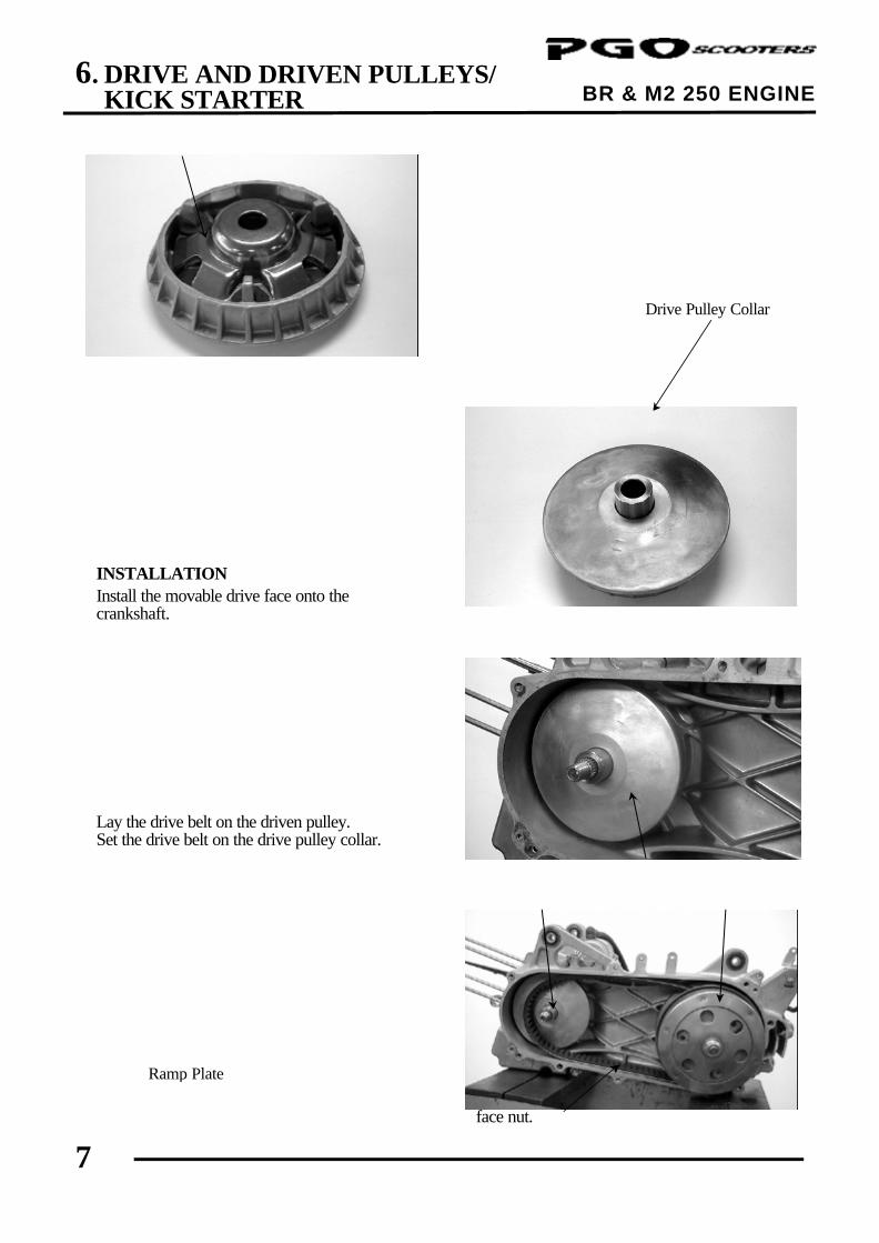
BR & M2 250 ENGINE Insert the drive pulley collar into the movable drive face. INSTALLATION Install the movable drive face onto the crankshaft. Lay the drive belt on the driven pulley. Set the drive belt on the drive pulley collar.
Install the drive pulley face, washer and drive face nut.
Drive Pulley Collar
Ramp Plate
Driven Pulley
Movable Drive Face Assembly
Drive Pulley Collar
Drive Belt
6. DRIVE AND DRIVEN PULLEYS/ KICK STARTER
8
BR & M2 250 ENGINE Hold the drive pulley with the universal holder and tighten the drive face nut. Torque: 49.0∼58.5N-m Universal Holder CLUTCH/DRIVEN PULLEY Remove the left crankcase cover. (ð6-3) Remove the drive pulley and drive belt. (ð6-4) Hold the clutch outer with the universal holder and remove the clutch outer nut. Universal Holder Remove the clutch outer. INSPECTION Inspect the clutch outer for wear or damage. Measure the clutch outer I.D. Service Limit: 153.5mm replace if over
Check the clutch shoes for wear or damage. Measure the clutch lining thickness.
Drive Pulley Face
Washer
Special
Special
• Do not get oil or grease on the drive belt or drive pulley faces.
*
Clutch Outer
Drive Face Nut
Drive Pulley
Universal Holder
Universal Holder
6. DRIVE AND DRIVEN PULLEYS/ KICK STARTER
9
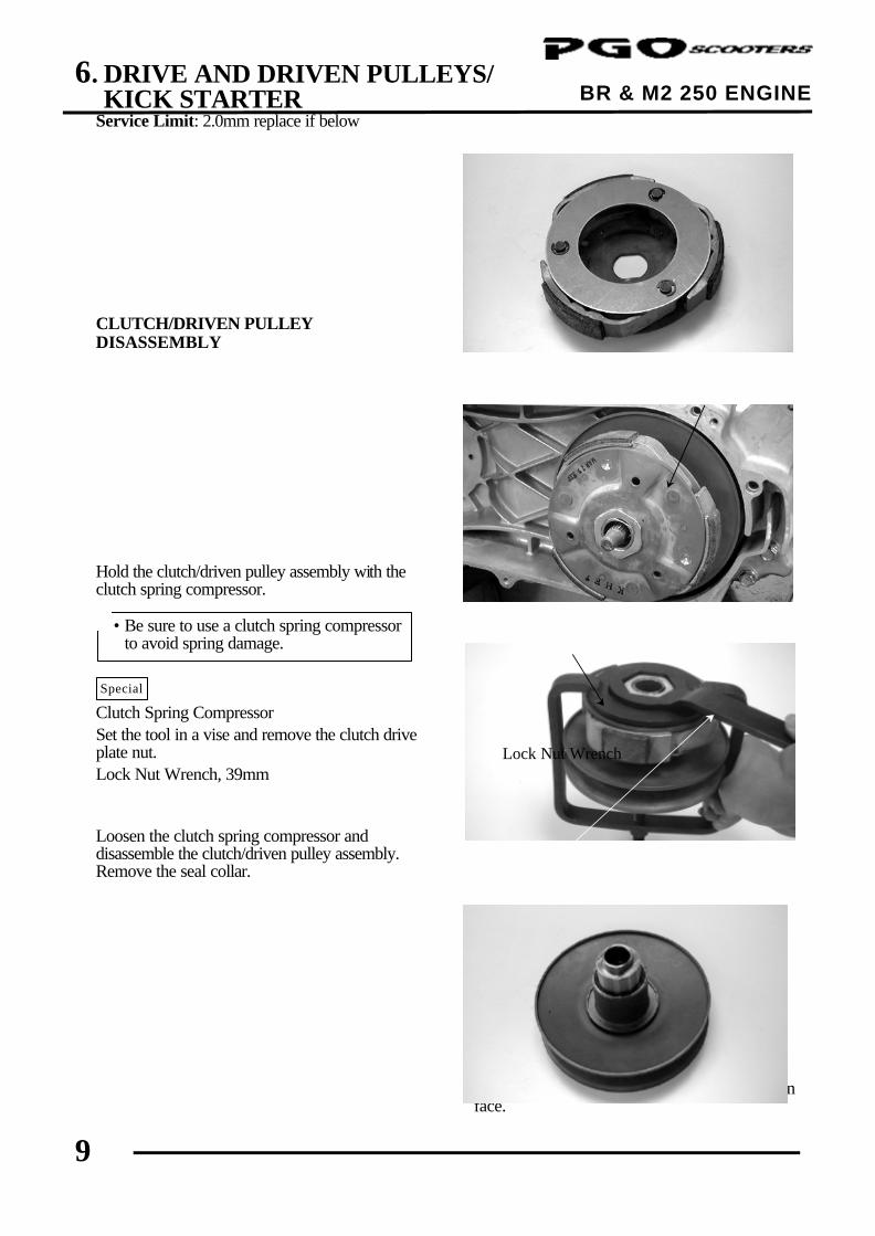
BR & M2 250 ENGINE Service Limit: 2.0mm replace if below
CLUTCH/DRIVEN PULLEY DISASSEMBLY Hold the clutch/driven pulley assembly with the clutch spring compressor. Clutch Spring Compressor Set the tool in a vise and remove the clutch drive plate nut. Lock Nut Wrench, 39mm Loosen the clutch spring compressor and disassemble the clutch/driven pulley assembly. Remove the seal collar.
Pull out the guide roller pins and guide rollers. Remove the movable driven face from the driven face.
Clutch/Driven Pulley
Special
Clutch Spring Compressor
• Be sure to use a clutch spring compressor to avoid spring damage.
*
Lock Nut Wrench
6. DRIVE AND DRIVEN PULLEYS/ KICK STARTER
10
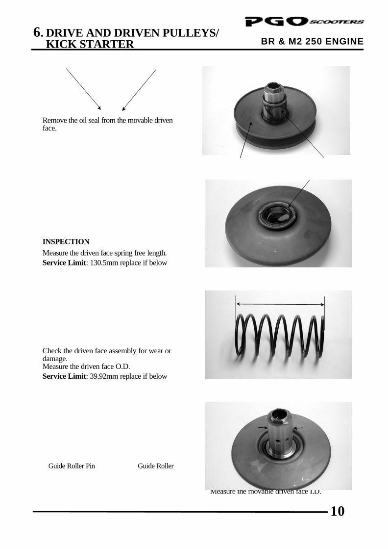
BR & M2 250 ENGINE Remove the oil seal from the movable driven face. INSPECTION Measure the driven face spring free length. Service Limit: 130.5mm replace if below Check the driven face assembly for wear or damage. Measure the driven face O.D. Service Limit: 39.92mm replace if below
Check the movable driven face for wear or damage. Measure the movable driven face I.D.
Movable Driven Face
Guide Roller Pin
O-ring
Guide Roller
Oil Seal
6. DRIVE AND DRIVEN PULLEYS/ KICK STARTER
11
BR & M2 250 ENGINE
Service Limit: 40.05mm replace if over
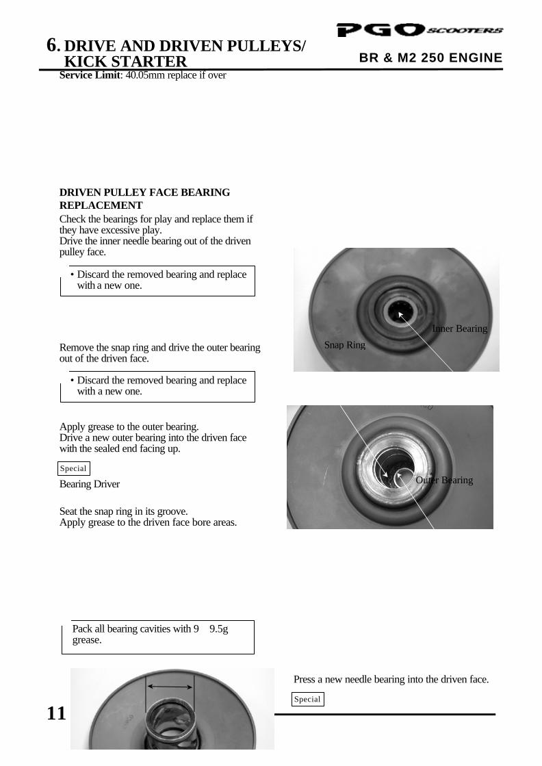
DRIVEN PULLEY FACE BEARING REPLACEMENT Check the bearings for play and replace them if they have excessive play. Drive the inner needle bearing out of the driven pulley face. Remove the snap ring and drive the outer bearing out of the driven face. Apply grease to the outer bearing. Drive a new outer bearing into the driven face with the sealed end facing up. Bearing Driver Seat the snap ring in its groove. Apply grease to the driven face bore areas.
Press a new needle bearing into the driven face.
Snap Ring
Inner Bearing
Outer Bearing
Special
• Discard the removed bearing and replace with a new one.
*
Pack all bearing cavities with 9∼9.5g grease.
*
• Discard the removed bearing and replace with a new one.
*
Special
6. DRIVE AND DRIVEN PULLEYS/ KICK STARTER
12
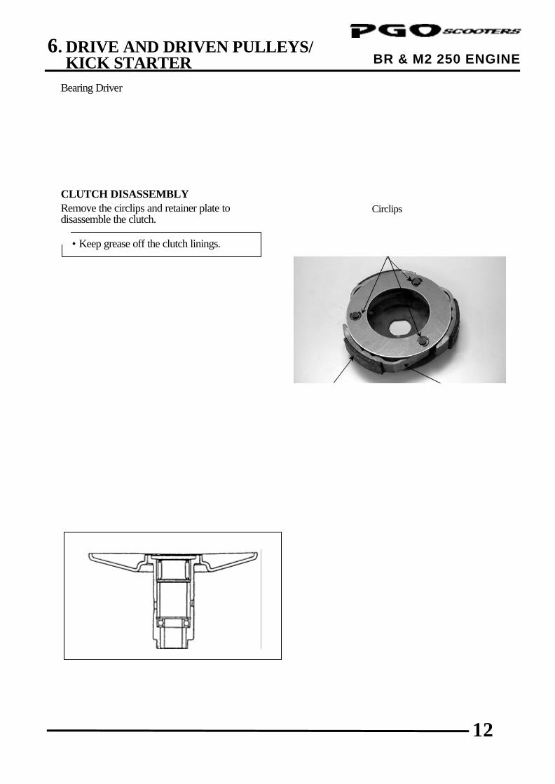
BR & M2 250 ENGINE Bearing Driver CLUTCH DISASSEMBLY Remove the circlips and retainer plate to disassemble the clutch.
Circlips
• Keep grease off the clutch linings. *
Retainer Plate Clutch Lining
6. DRIVE AND DRIVEN PULLEYS/ KICK STARTER
13
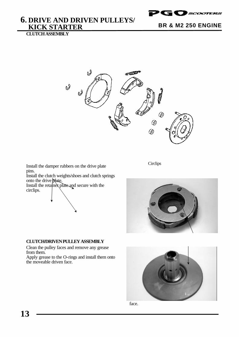
BR & M2 250 ENGINE CLUTCH ASSEMBLY Install the damper rubbers on the drive plate pins. Install the clutch weights/shoes and clutch springs onto the drive plate. Install the retainer plate and secure with the circlips. CLUTCH/DRIVEN PULLEY ASSEMBLY Clean the pulley faces and remove any grease from them. Apply grease to the O-rings and install them onto the moveable driven face.
Install the movable driven face onto the driven face.
Circlips
Drive Plate
Movable Driven Face
6. DRIVE AND DRIVEN PULLEYS/ KICK STARTER
14
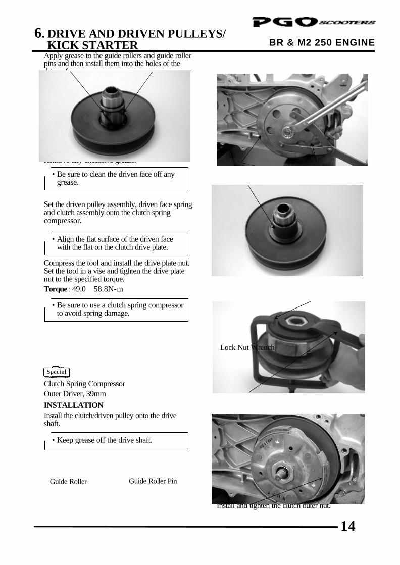
BR & M2 250 ENGINE Apply grease to the guide rollers and guide roller pins and then install them into the holes of the driven face. Install the seal collar. Remove any excessive grease. Set the driven pulley assembly, driven face spring and clutch assembly onto the clutch spring compressor. Compress the tool and install the drive plate nut. Set the tool in a vise and tighten the drive plate nut to the specified torque. Torque: 49.0∼58.8N-m Clutch Spring Compressor Outer Driver, 39mm INSTALLATION Install the clutch/driven pulley onto the drive shaft.
Install the clutch outer. Hold the clutch outer with the universal holder. Install and tighten the clutch outer nut.
• Be sure to clean the driven face off any grease.
*
• Align the flat surface of the driven face with the flat on the clutch drive plate.
*
• Keep grease off the drive shaft. *
Movable Driven Face
Guide Roller Pin
Seal Collar
Guide Roller
Clutch/Driven Pulley
Driven Face
Clutch Spring Compressor
Lock Nut Wrench
• Be sure to use a clutch spring compressor to avoid spring damage.
*
Special
6. DRIVE AND DRIVEN PULLEYS/ KICK STARTER
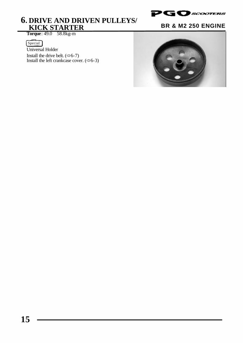
15
BR & M2 250 ENGINE Torque: 49.0∼58.8kg-m Universal Holder Install the drive belt. (ð6-7) Install the left crankcase cover. (ð6-3)
Special
7. FINAL REDUCTION
0
BR & M2 250 ENGINE
7 __________________________________________________________________________________
__________________________________________________________________________________
__________________________________________________________________________________
__________________________________________________________________________________
__________________________________________________________________________________
FINAL REDUCTION
__________________________________________________________________________________
SCHEMATIC DRAWING --------------------------------------------------- 7-1
SERVICE INFORMATION ------------------------------------------------- 7-2
TROUBLESHOOTING------------------------------------------------------- 7-2
FINAL REDUCTION DISASSEMBLY ----------------------------------- 7-3
FINAL REDUCTION INSPECTION-------------------------------------- 7-3
FINAL REDUCTION ASSEMBLY ---------------------------------------- 7-6
7
7. FINAL REDUCTION
1
BR & M2 250 ENGINE
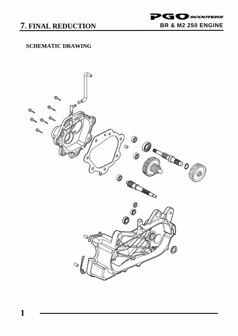
SCHEMATIC DRAWING
7. FINAL REDUCTION
2
BR & M2 250 ENGINE SERVICE INFORMATION GENERAL INSTRUCTIONS
• The servicing operations of this section can be made with the engine installed. • When replacing the drive shaft, use a special tool to hold the bearing inner race for this operation. SPECIFICATIONS
Specified Oil: SAE 90# Oil Capacity: At disassembly : 0.2 liter At change : 0.18 liter TORQUE VALUES
Transmission case cover bolt 25.5∼31.4N-m Oil check bolt 9.8∼14.7N-m SPECIAL TOOLS
Bearing remover, 12mm Bearing remover, 15mm Pilot, 12mm Pilot, 15mm TROUBLESHOOTING
Engine starts but motorcycle won‘t move • Damaged transmission • Seized or burnt transmission Abnormal noise • Worn, seized or chipped gears • Worn bearing Oil leaks • Oil level too high • Worn or damaged oil seal
7. FINAL REDUCTION
3
BR & M2 250 ENGINE
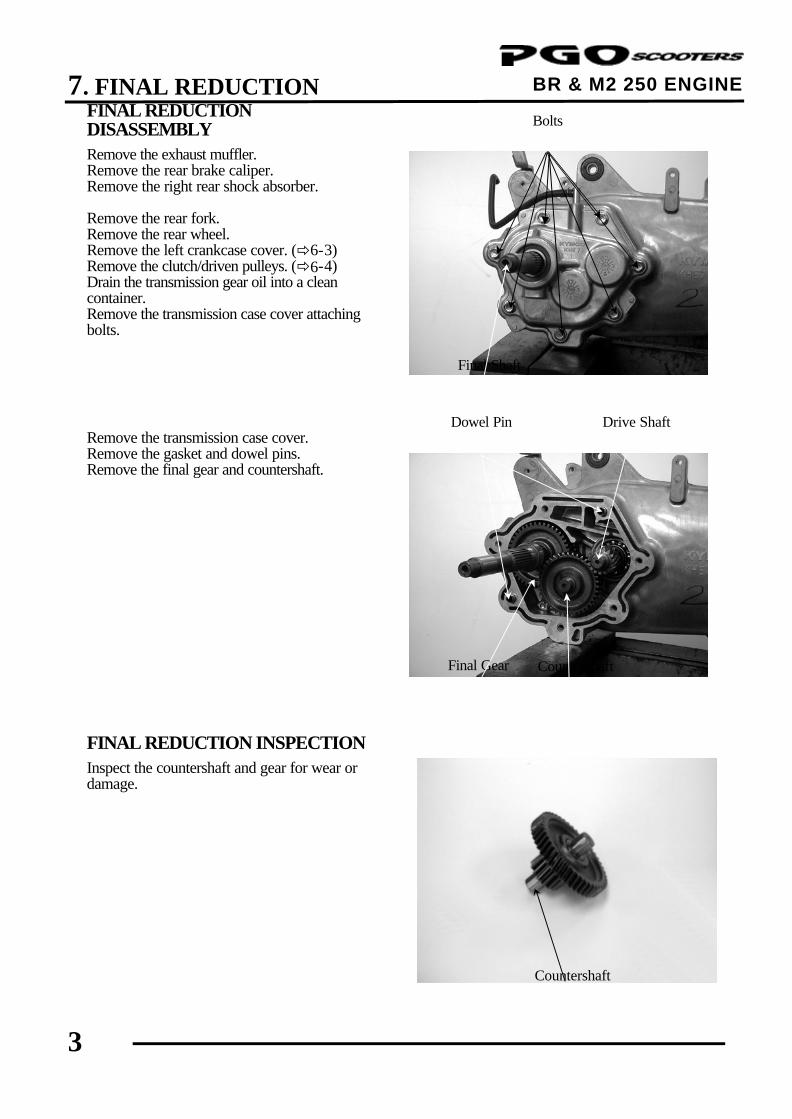
FINAL REDUCTION DISASSEMBLY Remove the exhaust muffler. Remove the rear brake caliper. Remove the right rear shock absorber. Remove the rear fork. Remove the rear wheel. Remove the left crankcase cover. (ð6-3) Remove the clutch/driven pulleys. (ð6-4) Drain the transmission gear oil into a clean container. Remove the transmission case cover attaching bolts. Remove the transmission case cover. Remove the gasket and dowel pins. Remove the final gear and countershaft. FINAL REDUCTION INSPECTION Inspect the countershaft and gear for wear or damage.
Final Shaft
Dowel Pin
Final Gear
Countershaft
Drive Shaft
Countershaft
Bolts
7. FINAL REDUCTION
4
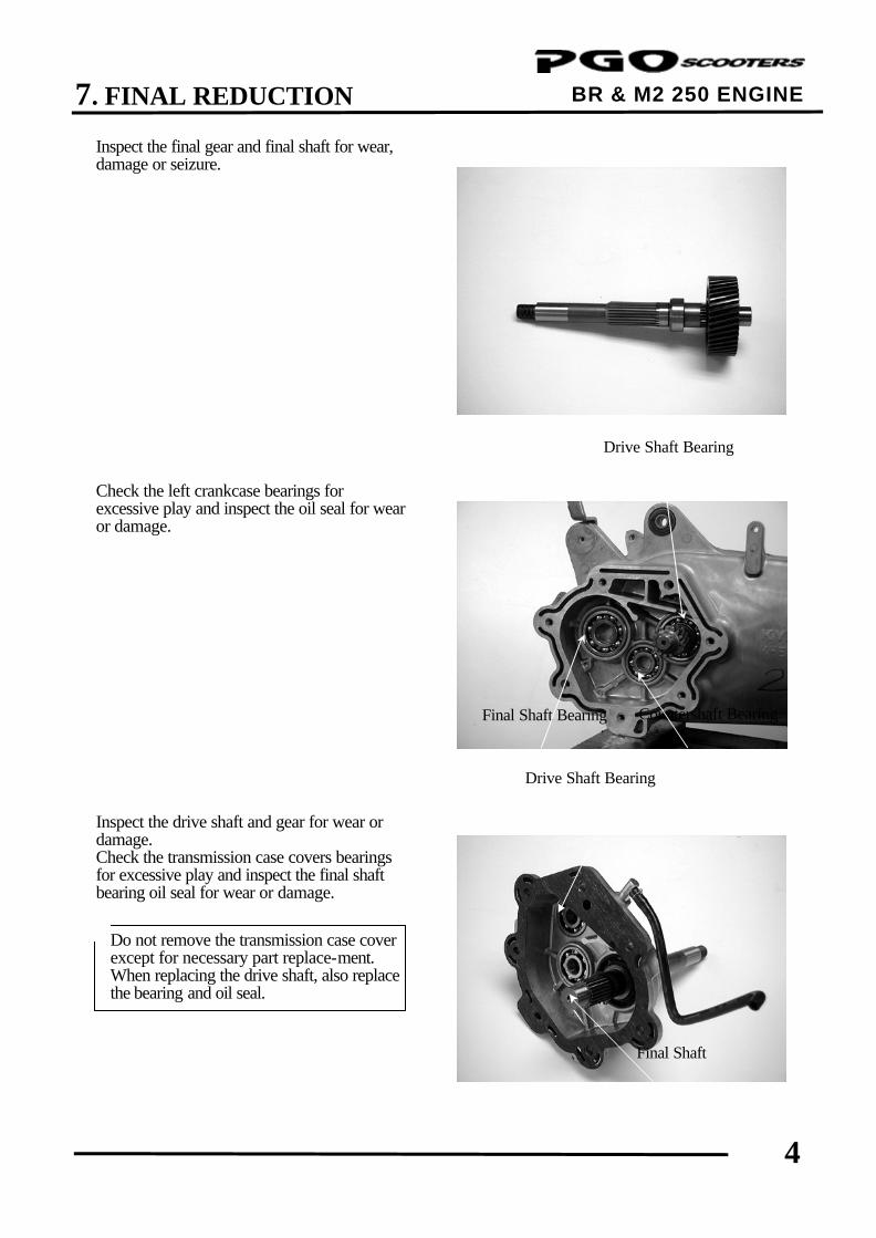
BR & M2 250 ENGINE Inspect the final gear and final shaft for wear, damage or seizure. Check the left crankcase bearings for excessive play and inspect the oil seal for wear or damage. Inspect the drive shaft and gear for wear or damage. Check the transmission case covers bearings for excessive play and inspect the final shaft bearing oil seal for wear or damage.
Drive Shaft Bearing
Final Shaft Bearing Countershaft Bearing
Do not remove the transmission case cover except for necessary part replace-ment. When replacing the drive shaft, also replace the bearing and oil seal.
*
Drive Shaft Bearing
Final Shaft
7. FINAL REDUCTION
5
BR & M2 250 ENGINE
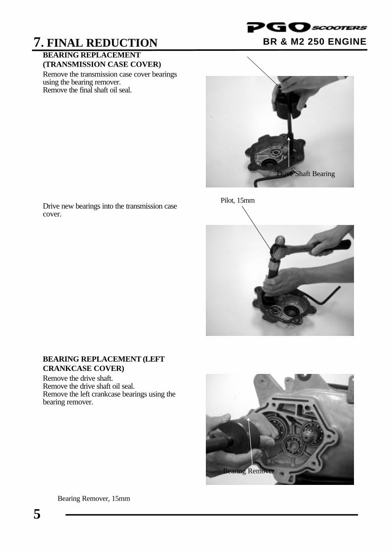
BEARING REPLACEMENT (TRANSMISSION CASE COVER) Remove the transmission case cover bearings using the bearing remover. Remove the final shaft oil seal. Drive new bearings into the transmission case cover. BEARING REPLACEMENT (LEFT CRANKCASE COVER) Remove the drive shaft. Remove the drive shaft oil seal. Remove the left crankcase bearings using the bearing remover.
Drive Shaft Bearing
Bearing Remover, 15mm
Pilot, 15mm
Bearing Remover
7. FINAL REDUCTION
6
BR & M2 250 ENGINE
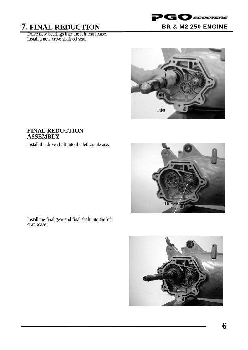
Drive new bearings into the left crankcase. Install a new drive shaft oil seal. FINAL REDUCTION ASSEMBLY Install the drive shaft into the left crankcase. Install the final gear and final shaft into the left crankcase.
Pilot
Drive Shaft
7. FINAL REDUCTION
7
BR & M2 250 ENGINE
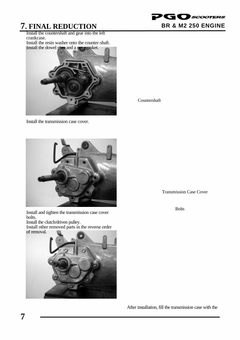
Install the countershaft and gear into the left crankcase. Install the resin washer onto the counter-shaft. Install the dowel pins and a new gasket.
Install the transmission case cover. Install and tighten the transmission case cover bolts. Install the clutch/driven pulley. Install other removed parts in the reverse order of removal.
After installation, fill the transmission case with the
Countershaft
Transmission Case Cover
Bolts
7. FINAL REDUCTION
8
BR & M2 250 ENGINE
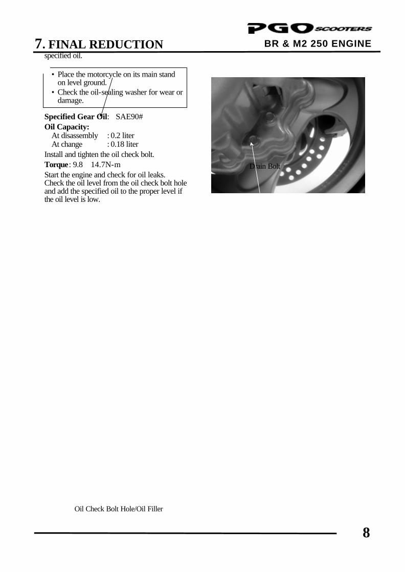
specified oil. Specified Gear Oil: SAE90# Oil Capacity: At disassembly : 0.2 liter At change : 0.18 liter Install and tighten the oil check bolt. Torque: 9.8∼14.7N-m Start the engine and check for oil leaks. Check the oil level from the oil check bolt hole and add the specified oil to the proper level if the oil level is low.
• Place the motorcycle on its main stand on level ground.
• Check the oil-sealing washer for wear or damage.
*
Drain Bolt
Oil Check Bolt Hole/Oil Filler
8. CARBURETOR
BR & M2 250 ENGINE
7 _________________________________________________________________________________
_________________________________________________________________________________
_________________________________________________________________________________
_________________________________________________________________________________
_________________________________________________________________________________
CARBURETOR
_________________________________________________________________________________
DIAPHRAGM AND PISTON OPERATION---------------------------------------------- 8-1
SLOW SYSTEM----------------------------------------------------------------------- 8-2
COASTING ENRICHMENT SYSTEM--------------------------------------------------- 8-2
MAIN SYSTEM----------------------------------------------------------------------- 8-4
AUTO-ENRICHENER (AUTO-CHOKE) SYSTEM--------------------------------------- 8-5
FLOAT SYSTEM---------------------------------------------------------------------- 8-6
ACCELERATOR PUMP SYSTEM------------------------------------------------------- 8-7
INSPECTION------------------------------------------------------------------------- 8-9
8
8. CARBURETOR
BR & M2 250 ENGINE
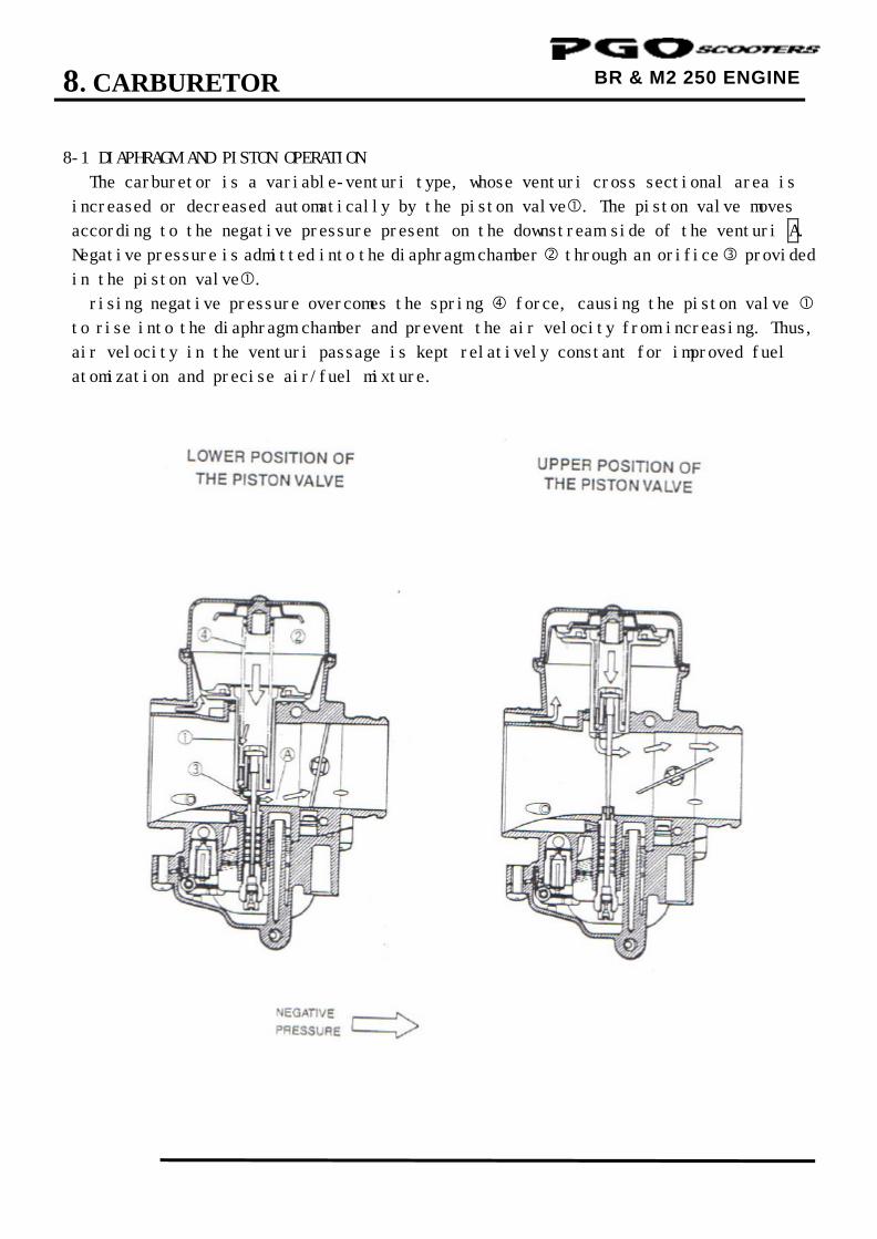
8-1 DIAPHRAGM AND PISTON OPERATION
The carburetor is a variable-venturi type, whose venturi cross sectional area is
increased or decreased automatically by the piston valve. The piston valve moves
according to the negative pressure present on the downstream side of the venturi A.
Negative pressure is admitted into the diaphragm chamber through an orifice provided
in the piston valve.
rising negative pressure overcomes the spring force, causing the piston valve
to rise into the diaphragm chamber and prevent the air velocity from increasing. Thus,
air velocity in the venturi passage is kept relatively constant for improved fuel
atomization and precise air/fuel mixture.
8. CARBURETOR
BR & M2 250 ENGINE
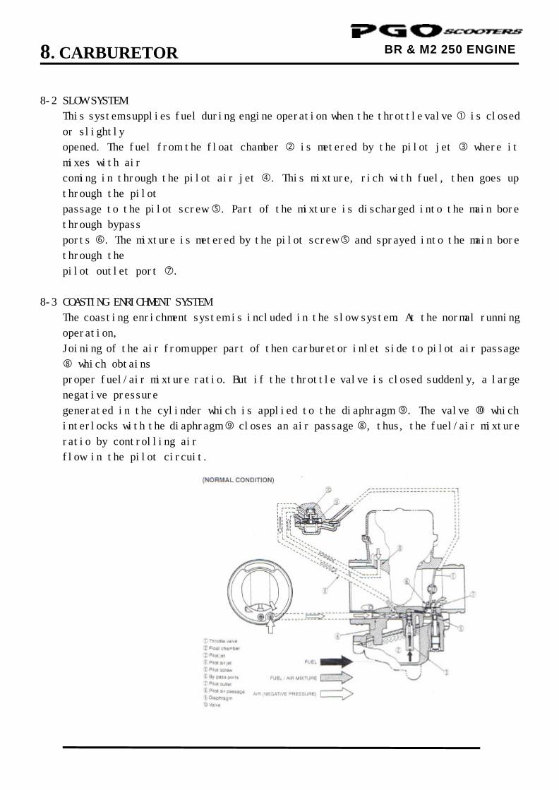
8-2 SLOW SYSTEM
This system supplies fuel during engine operation when the throttle valve is closed
or slightly
opened. The fuel from the float chamber is metered by the pilot jet where it
mixes with air
coming in through the pilot air jet . This mixture, rich with fuel, then goes up
through the pilot
passage to the pilot screw . Part of the mixture is discharged into the main bore
through bypass
ports . The mixture is metered by the pilot screw and sprayed into the main bore
through the
pilot outlet port .
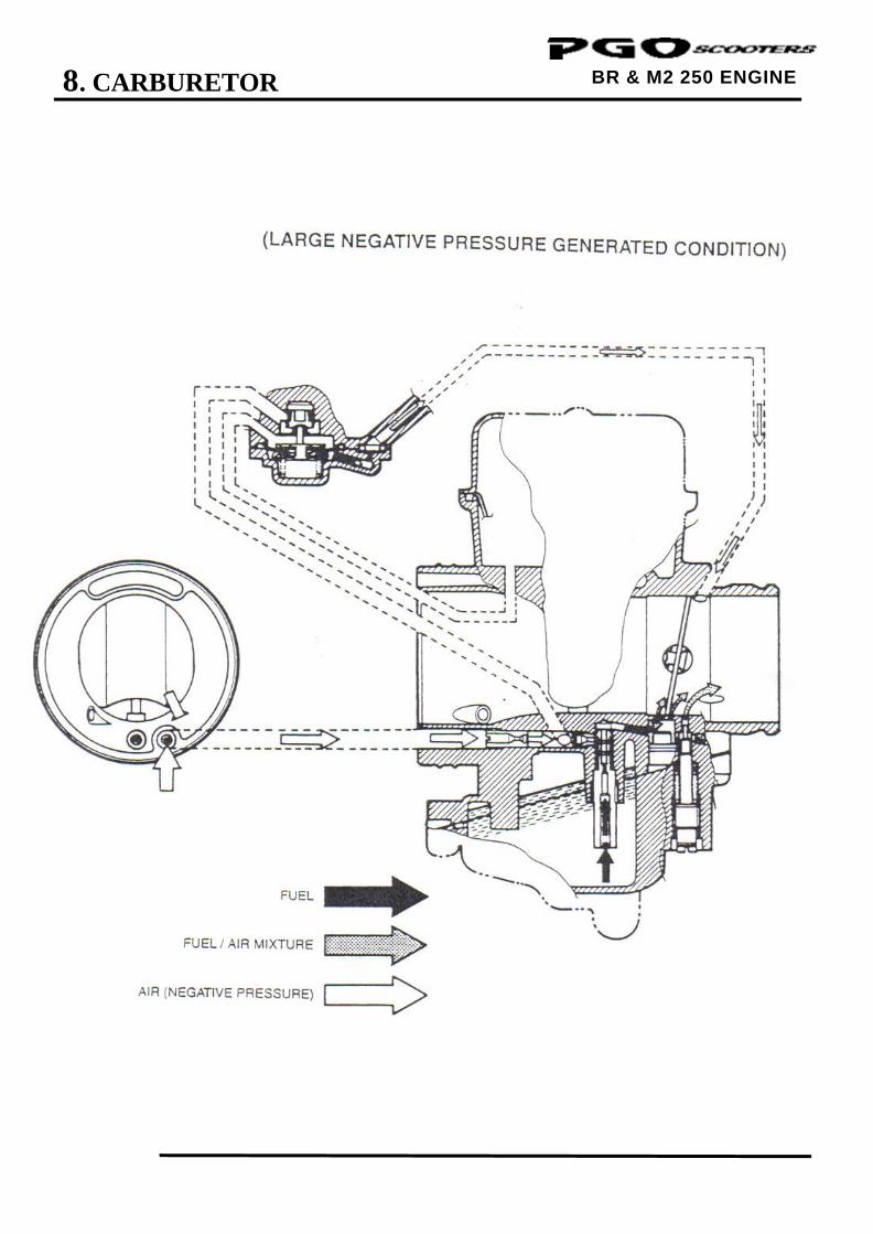
8-3 COASTING ENRICHMENT SYSTEM
The coasting enrichment system is included in the slow system. At the normal running
operation,
Joining of the air from upper part of then carburetor inlet side to pilot air passage
which obtains
proper fuel/air mixture ratio. But if the throttle valve is closed suddenly, a large
negative pressure
generated in the cylinder which is applied to the diaphragm . The valve which
interlocks with the diaphragm closes an air passage , thus, the fuel/air mixture
ratio by controlling air
flow in the pilot circuit.
8. CARBURETOR
BR & M2 250 ENGINE
8. CARBURETOR
BR & M2 250 ENGINE
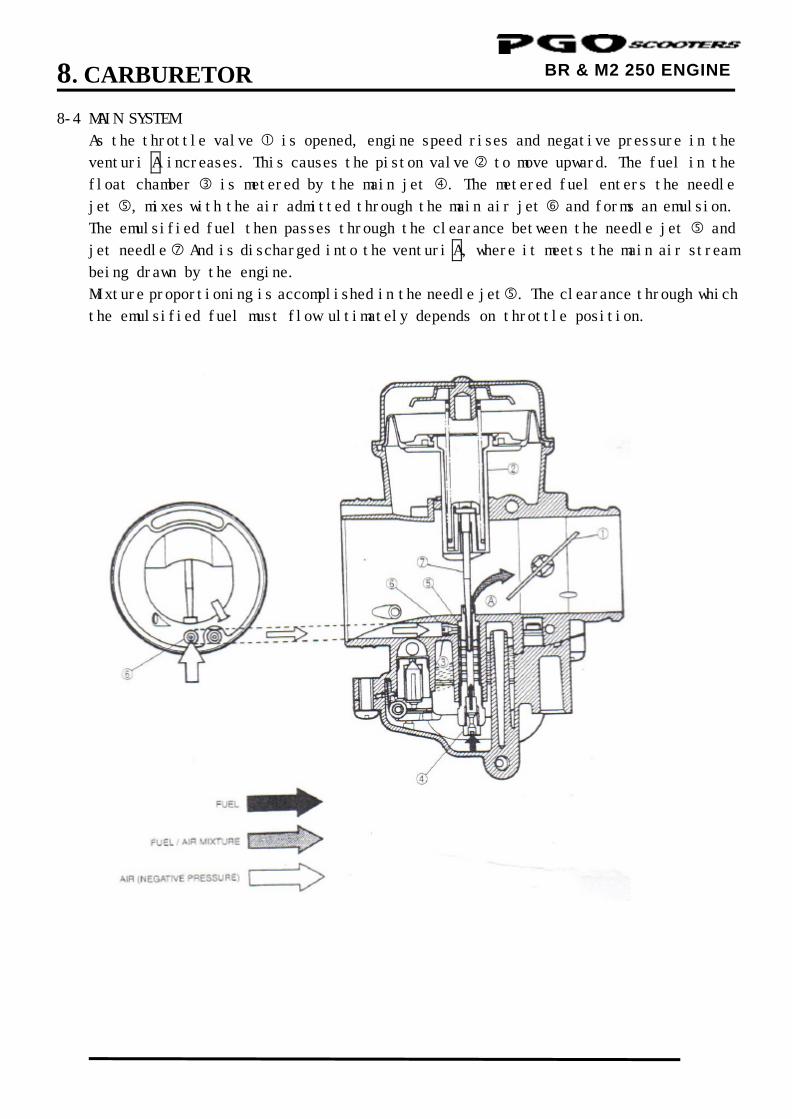
8-4 MAIN SYSTEM
As the throttle valve is opened, engine speed rises and negative pressure in the
venturi A increases. This causes the piston valve to move upward. The fuel in the
float chamber is metered by the main jet . The metered fuel enters the needle
jet , mixes with the air admitted through the main air jet and forms an emulsion.
The emulsified fuel then passes through the clearance between the needle jet and
jet needle And is discharged into the venturi A, where it meets the main air stream
being drawn by the engine.
Mixture proportioning is accomplished in the needle jet . The clearance through which
the emulsified fuel must flow ultimately depends on throttle position.
8. CARBURETOR
BR & M2 250 ENGINE
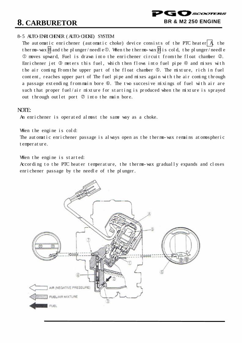
8-5 AUTO-ENRICHENER (AUTO-CHOKE) SYSTEM
The automatic enrichener (automatic choke) device consists of the PTC heater A, the
thermo-wax B and the plunger/needle . When the thermo-wax B is cold, the plunger/needle
moves upward, Fuel is drawn into the enrichener circuit from the float chamber .
Enrichener jet meters this fuel, which then flows into fuel pipe and mixes with
the air coming From the upper part of the float chamber . The mixture, rich in fuel
content, reaches upper part of The fuel pipe and mixes again with the air coming through
a passage extending from main bore . The two succesive mixings of fuel with air are
such that proper fuel/air mixture for starting is produced when the mixture is sprayed
out through outlet port into the main bore.
NOTE:
An enrichener is operated almost the same way as a choke.
When the engine is cold:
The automatic enrichener passage is always open as the thermo-wax remains atomospheric
temperature.
When the engine is started:
According to the PTC heater temperature, the thermo-wax gradually expands and closes
enrichener passage by the needle of the plunger.
8. CARBURETOR
BR & M2 250 ENGINE
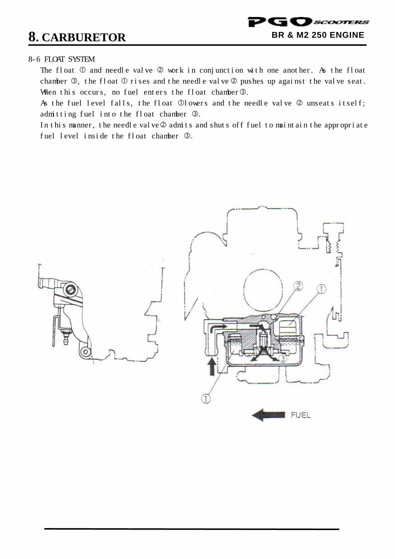
8-6 FLOAT SYSTEM
The float and needle valve work in conjunction with one another. As the float
chamber , the float rises and the needle valve pushes up against the valve seat.
When this occurs, no fuel enters the float chamber.
As the fuel level falls, the float lowers and the needle valve unseats itself;
admitting fuel into the float chamber .
In this manner, the needle valve admits and shuts off fuel to maintain the appropriate
fuel level inside the float chamber .
8. CARBURETOR
BR & M2 250 ENGINE
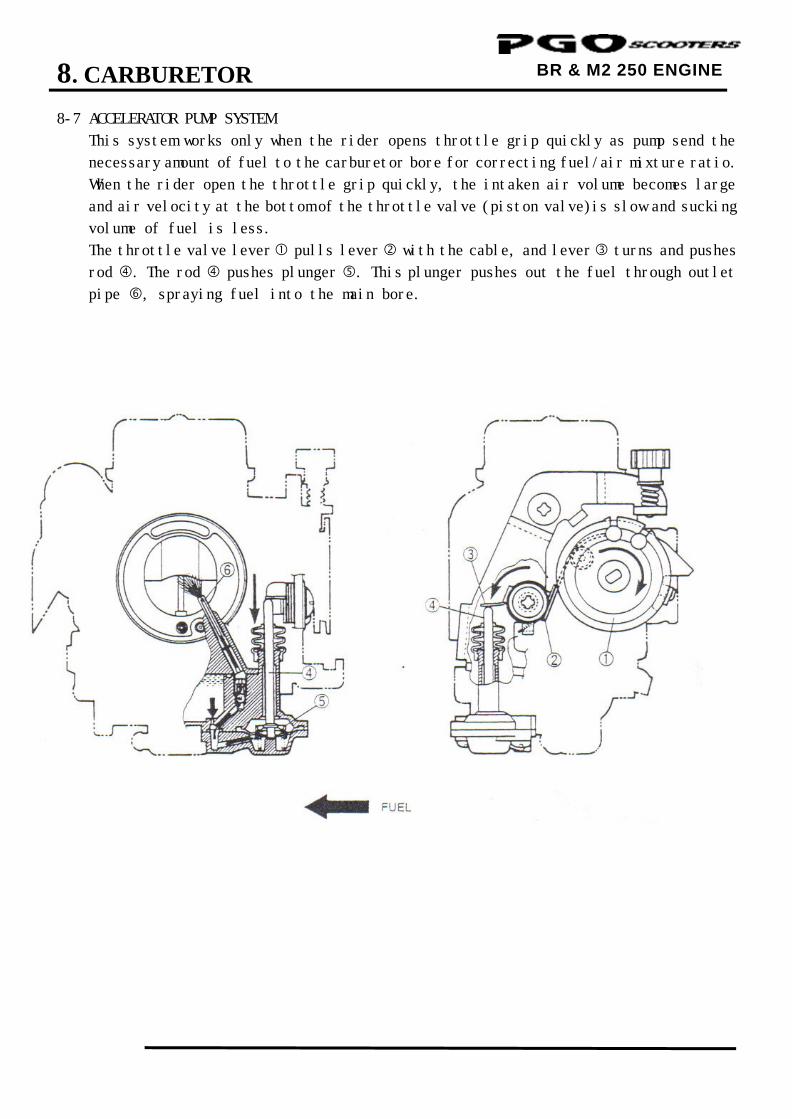
8-7 ACCELERATOR PUMP SYSTEM
This system works only when the rider opens throttle grip quickly as pump send the
necessary amount of fuel to the carburetor bore for correcting fuel/air mixture ratio.
When the rider open the throttle grip quickly, the intaken air volume becomes large
and air velocity at the bottom of the throttle valve (piston valve)is slow and sucking
volume of fuel is less.
The throttle valve lever pulls lever with the cable, and lever turns and pushes
rod . The rod pushes plunger . This plunger pushes out the fuel through outlet
pipe , spraying fuel into the main bore.
8. CARBURETOR
BR & M2 250 ENGINE
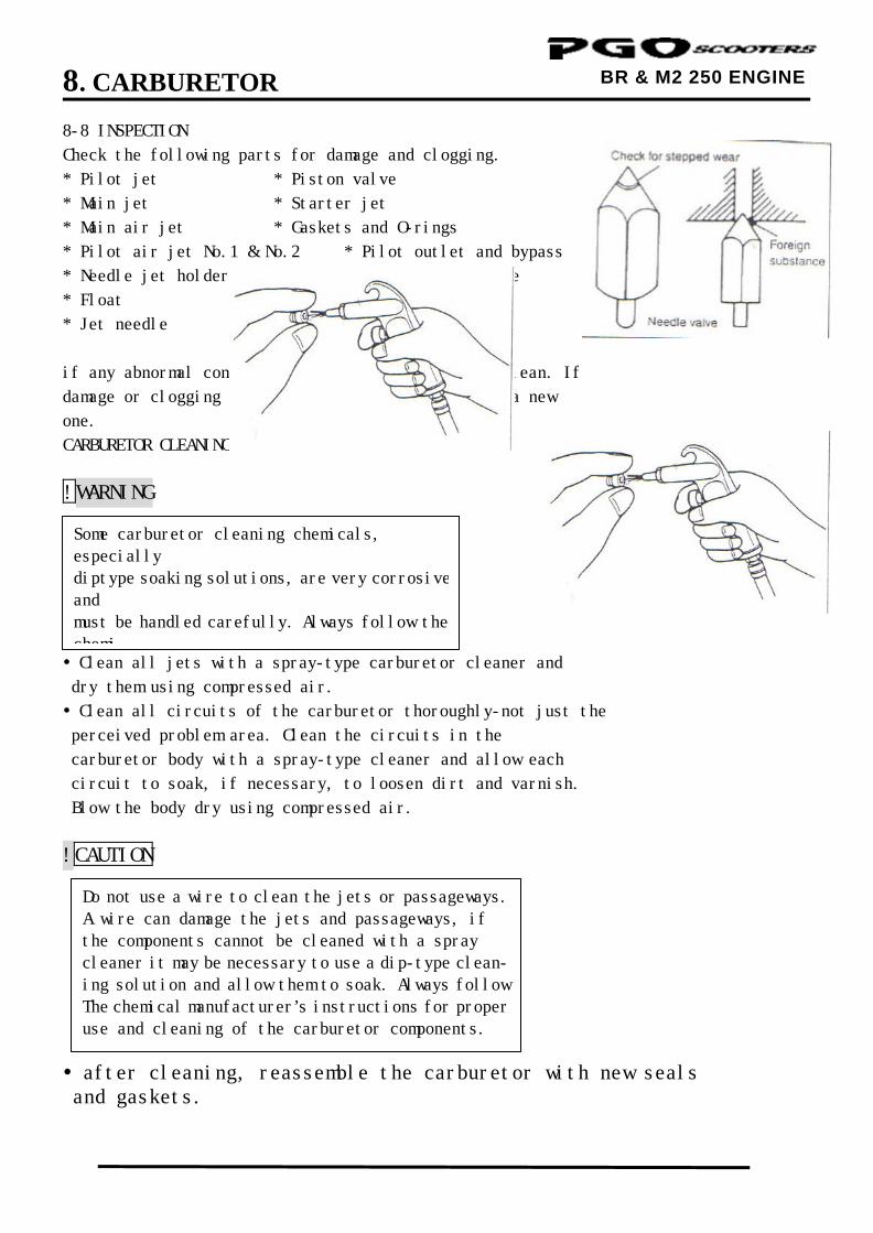
8-8 INSPECTION
Check the following parts for damage and clogging.
* Pilot jet * Piston valve
* Main jet * Starter jet
* Main air jet * Gaskets and O-rings
* Pilot air jet No.1 & No.2 * Pilot outlet and bypass
* Needle jet holder * Coasting enrichement valve
* Float * Needle valve
* Jet needle * Valve seat
if any abnormal condition is found, wash the part clean. If
damage or clogging is found, replace the part with a new
one.
CARBURETOR CLEANING
!WARNING
Clean all jets with a spray-type carburetor cleaner and
dry them using compressed air.
Clean all circuits of the carburetor thoroughly-not just the
perceived problem area. Clean the circuits in the
carburetor body with a spray-type cleaner and allow each
circuit to soak, if necessary, to loosen dirt and varnish.
Blow the body dry using compressed air.
!CAUTION after cleaning, reassemble the carburetor with new seals and gaskets.
Some carburetor cleaning chemicals, especially diptype soaking solutions, are very corrosive and must be handled carefully. Always follow the chemi-
Do not use a wire to clean the jets or passageways. A wire can damage the jets and passageways, if the components cannot be cleaned with a spray cleaner it may be necessary to use a dip-type clean- ing solution and allow them to soak. Always follow The chemical manufacturer’s instructions for proper use and cleaning of the carburetor components.
8. CARBURETOR
10
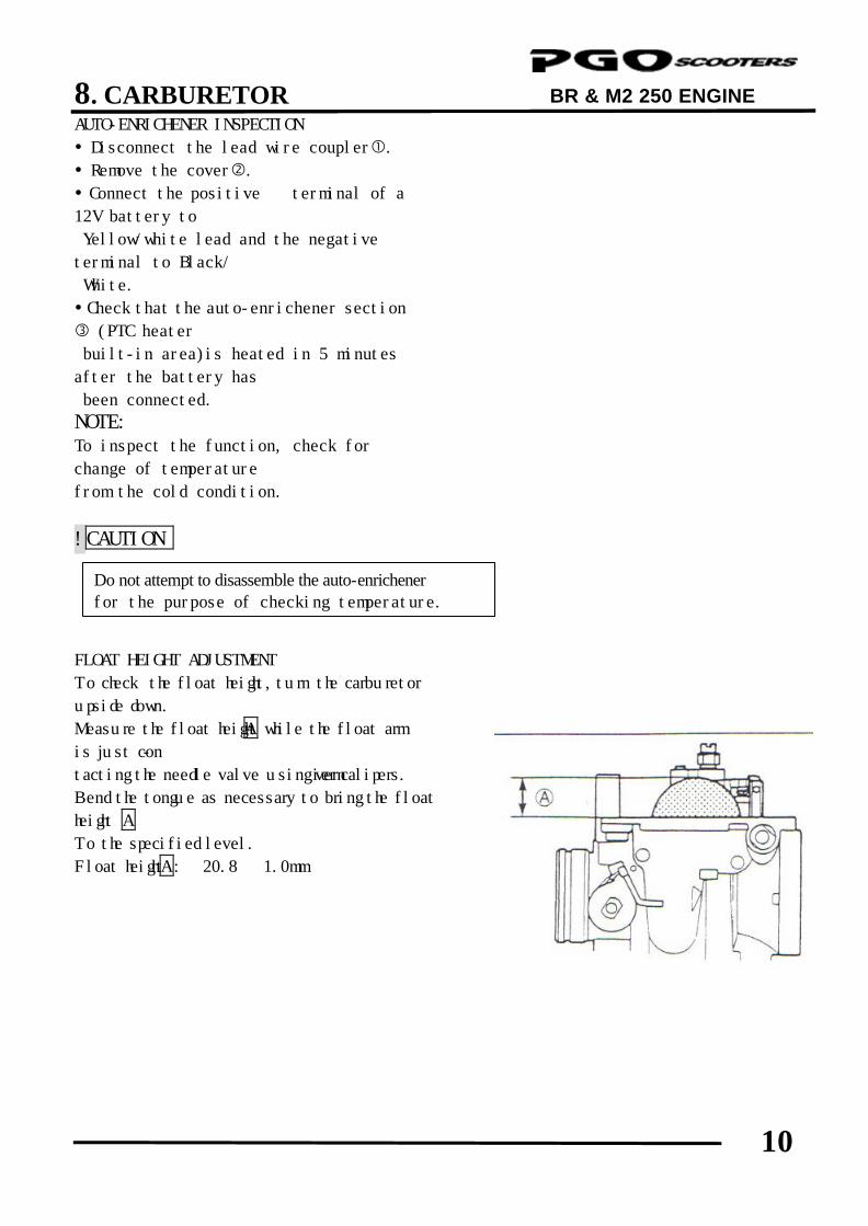
BR & M2 250 ENGINE AUTO-ENRICHENER INSPECTION
Disconnect the lead wire coupler. Remove the cover. Connect the positive ⊕ terminal of a
12V battery to
Yellow/white lead and the negative Θ
terminal to Black/
White.
Check that the auto-enrichener section
(PTC heater
built-in area)is heated in 5 minutes
after the battery has
been connected.
NOTE:
To inspect the function, check for
change of temperature
from the cold condition.
!CAUTION
FLOAT HEIGHT ADJUSTMENT
To check the float height, turn the carburetor
upside down.
Measure the float height A while the float arm
is just con-
tacting the needle valve using vernier calipers.
Bend the tongue as necessary to bring the float
height A
To the specified level.
Float height A: 20.8 ± 1.0mm
Do not attempt to disassemble the auto-enrichener for the purpose of checking temperature.
9. A.C. GENERATOR/STARTER CLUTCH
0
BR & M2 250 ENGINE ENGINE
9 __________________________________________________________________________________
__________________________________________________________________________________
__________________________________________________________________________________
__________________________________________________________________________________
__________________________________________________________________________________
A.C. GENERATOR/STARTER CLUTCH
__________________________________________________________________________________
SCHEMATIC DRAWING --------------------------------------------------- 9-1
SERVICE INFORMATION ------------------------------------------------- 9-2
TROUBLESHOOTING------------------------------------------------------- 9-2
RIGHT CRANKCASE COVER REMOVAL ---------------------------- 9-3
STATOR REMOVAL--------------------------------------------------------- 9-3
FLYWHEEL REMOVAL----------------------------------------------------- 9-3
STARTER CLUTCH---------------------------------------------------------- 9-4
FLYWHEEL INSTALLATION --------------------------------------------- 9-5
STATOR INSTALLATION ------------------------------------------------- 9-6
RIGHT CRANKCASE COVER INSTALLATION--------------------- 9-6
9
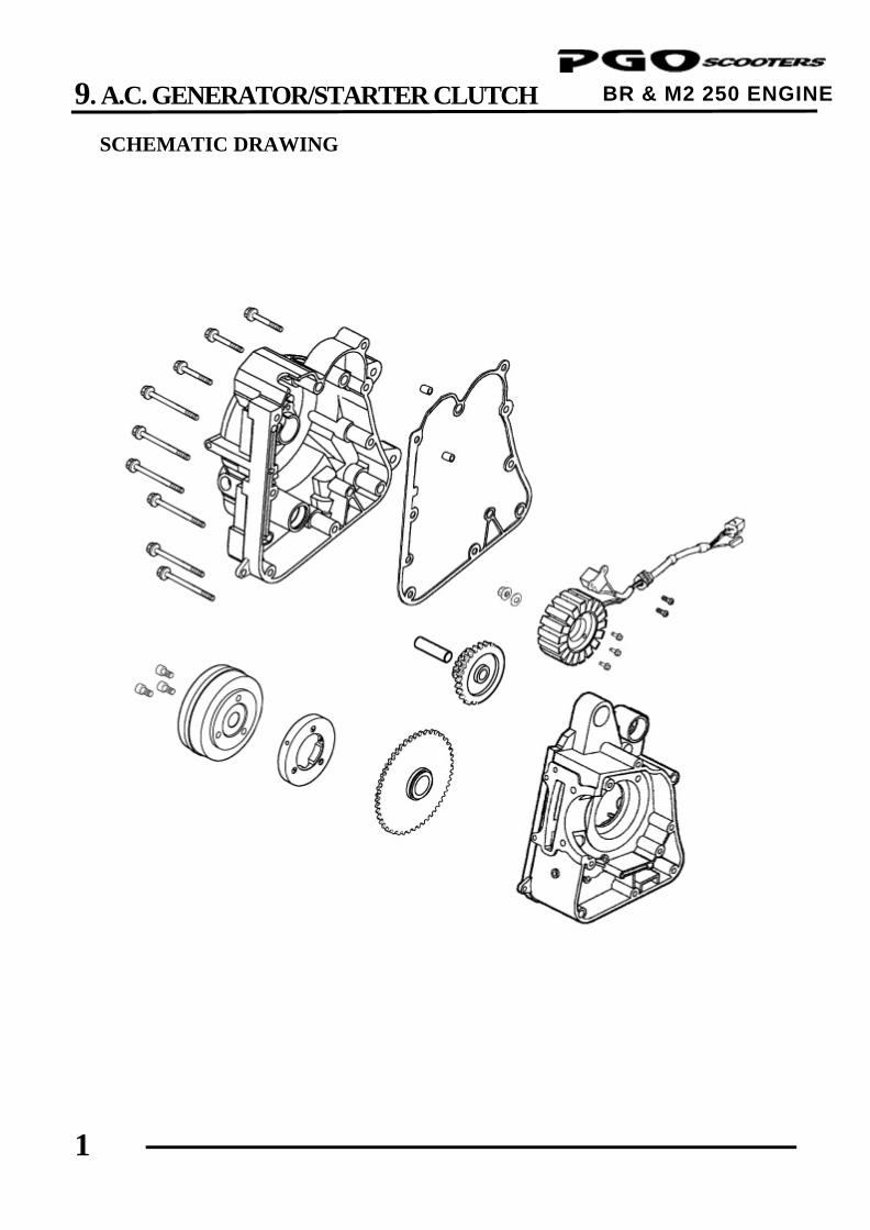
9. A.C. GENERATOR/STARTER CLUTCH
1
BR & M2 250 ENGINE SCHEMATIC DRAWING
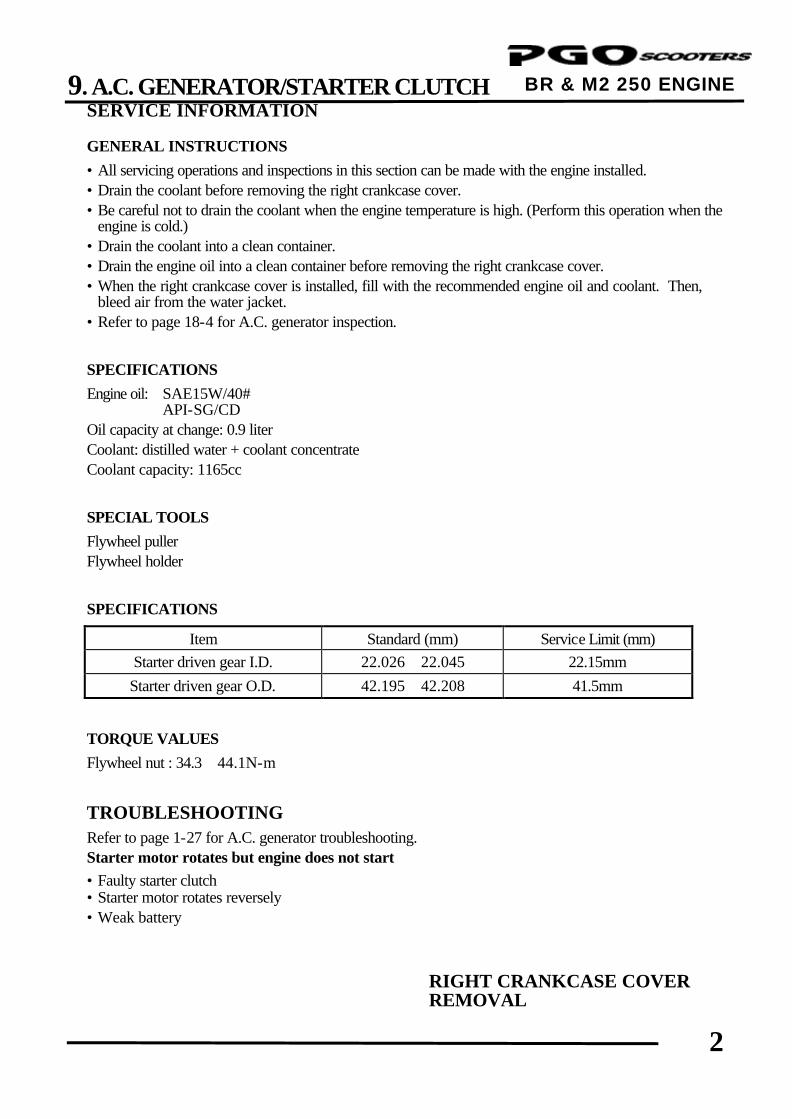
9. A.C. GENERATOR/STARTER CLUTCH
2
BR & M2 250 ENGINE ENGINE SERVICE INFORMATION
GENERAL INSTRUCTIONS
• All servicing operations and inspections in this section can be made with the engine installed. • Drain the coolant before removing the right crankcase cover. • Be careful not to drain the coolant when the engine temperature is high. (Perform this operation when the
engine is cold.) • Drain the coolant into a clean container. • Drain the engine oil into a clean container before removing the right crankcase cover. • When the right crankcase cover is installed, fill with the recommended engine oil and coolant. Then,
bleed air from the water jacket. • Refer to page 18-4 for A.C. generator inspection. SPECIFICATIONS
Engine oil: SAE15W/40# API-SG/CD Oil capacity at change: 0.9 liter Coolant: distilled water + coolant concentrate Coolant capacity: 1165cc SPECIAL TOOLS
Flywheel puller Flywheel holder SPECIFICATIONS
Item Standard (mm) Service Limit (mm) Starter driven gear I.D. 22.026∼22.045 22.15mm Starter driven gear O.D. 42.195∼42.208 41.5mm
TORQUE VALUES
Flywheel nut : 34.3∼44.1N-m TROUBLESHOOTING Refer to page 1-27 for A.C. generator troubleshooting. Starter motor rotates but engine does not start • Faulty starter clutch • Starter motor rotates reversely • Weak battery
RIGHT CRANKCASE COVER REMOVAL
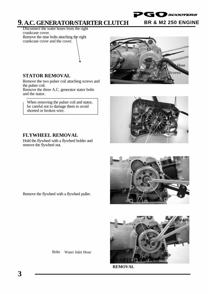
9. A.C. GENERATOR/STARTER CLUTCH
3
BR & M2 250 ENGINE
Disconnect the water hoses from the right crankcase cover. Remove the nine bolts attaching the right crankcase cover and the cover. STATOR REMOVAL Remove the two pulser coil attaching screws and the pulser coil. Remove the three A.C. generator stator bolts and the stator. FLYWHEEL REMOVAL Hold the flywheel with a flywheel holder and remove the flywheel nut. Remove the flywheel with a flywheel puller.
STARTER CLUTCH REMOVAL
Water Outlet Hose
Bolts
Flywheel Nut
Flywheel Holder
When removing the pulser coil and stator, be careful not to damage them to avoid shorted or broken wire.
*
Water Inlet Hose
Screws
Bolts Pulser Coil
A.C. Generator Stator
Flywheel Puller
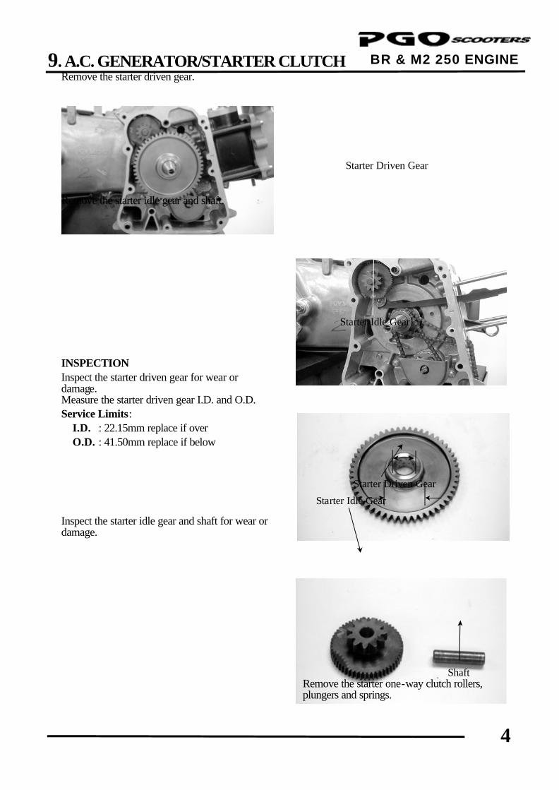
9. A.C. GENERATOR/STARTER CLUTCH
4
BR & M2 250 ENGINE ENGINE
Remove the starter driven gear. Remove the starter idle gear and shaft. INSPECTION Inspect the starter driven gear for wear or damage. Measure the starter driven gear I.D. and O.D. Service Limits: I.D. : 22.15mm replace if over O.D. : 41.50mm replace if below Inspect the starter idle gear and shaft for wear or damage.
Remove the starter one-way clutch rollers, plungers and springs.
Starter Driven Gear
Starter Idle Gear
Starter Driven Gear
Starter Idle Gear
Shaft
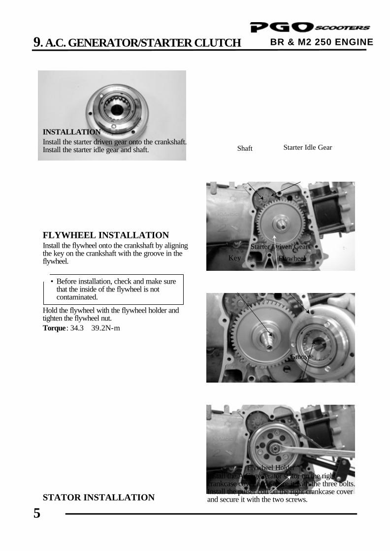
9. A.C. GENERATOR/STARTER CLUTCH
5
BR & M2 250 ENGINE
INSTALLATION Install the starter driven gear onto the crankshaft. Install the starter idle gear and shaft. FLYWHEEL INSTALLATION Install the flywheel onto the crankshaft by aligning the key on the crankshaft with the groove in the flywheel. Hold the flywheel with the flywheel holder and tighten the flywheel nut. Torque: 34.3∼39.2N-m
STATOR INSTALLATION
Install the A.C. generator stator on the right crankcase cover and secure it with the three bolts. Install the pulser coil on the right crankcase cover and secure it with the two screws.
Starter Idle Gear Shaft
Groove
• Before installation, check and make sure that the inside of the flywheel is not contaminated.
*
Starter Driven Gear
Flywheel Key
Flywheel Holder
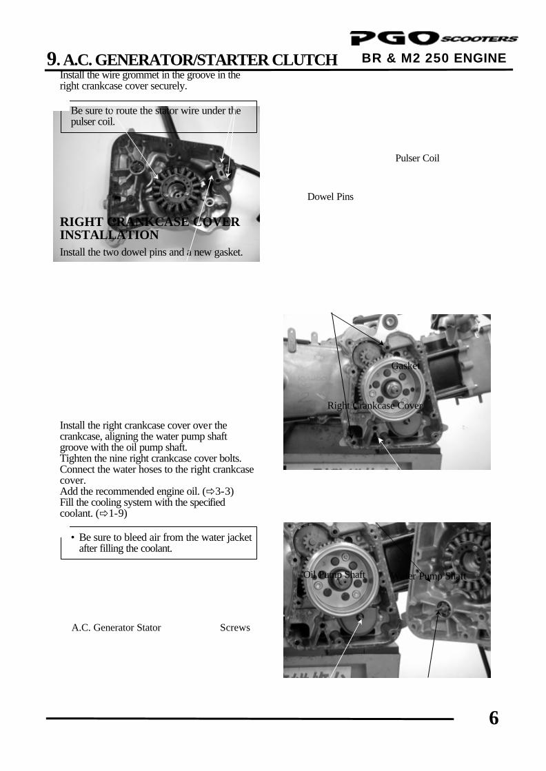
9. A.C. GENERATOR/STARTER CLUTCH
6
BR & M2 250 ENGINE ENGINE
Install the wire grommet in the groove in the right crankcase cover securely. RIGHT CRANKCASE COVER INSTALLATION Install the two dowel pins and a new gasket. Install the right crankcase cover over the crankcase, aligning the water pump shaft groove with the oil pump shaft. Tighten the nine right crankcase cover bolts. Connect the water hoses to the right crankcase cover. Add the recommended engine oil. (ð3-3) Fill the cooling system with the specified coolant. (ð1-9)
Right Crankcase Cover
Oil Pump Shaft
Dowel Pins
Be sure to route the stator wire under the pulser coil.
*
Screws
Gasket
Pulser Coil
A.C. Generator Stator
Water Pump Shaft
• Be sure to bleed air from the water jacket after filling the coolant.
*
10. CRANKCASE/CRANKSHAFT
0
BR & M2 250 ENGINE
10 __________________________________________________________________________________
__________________________________________________________________________________
__________________________________________________________________________________
__________________________________________________________________________________
__________________________________________________________________________________
CRANKCASE/CRANKSHAFT
__________________________________________________________________________________
SCHEMATIC DRAWING --------------------------------------------------- 10-1
SERVICE INFORMATION ------------------------------------------------- 10-2
TROUBLESHOOTING------------------------------------------------------- 10-2
CRANKCASE SEPARATION---------------------------------------------- 10-3
CRANKSHAFT INSPECTION--------------------------------------------- 10-4
CRANKCASE ASSEMBLY ------------------------------------------------- 10-5
10
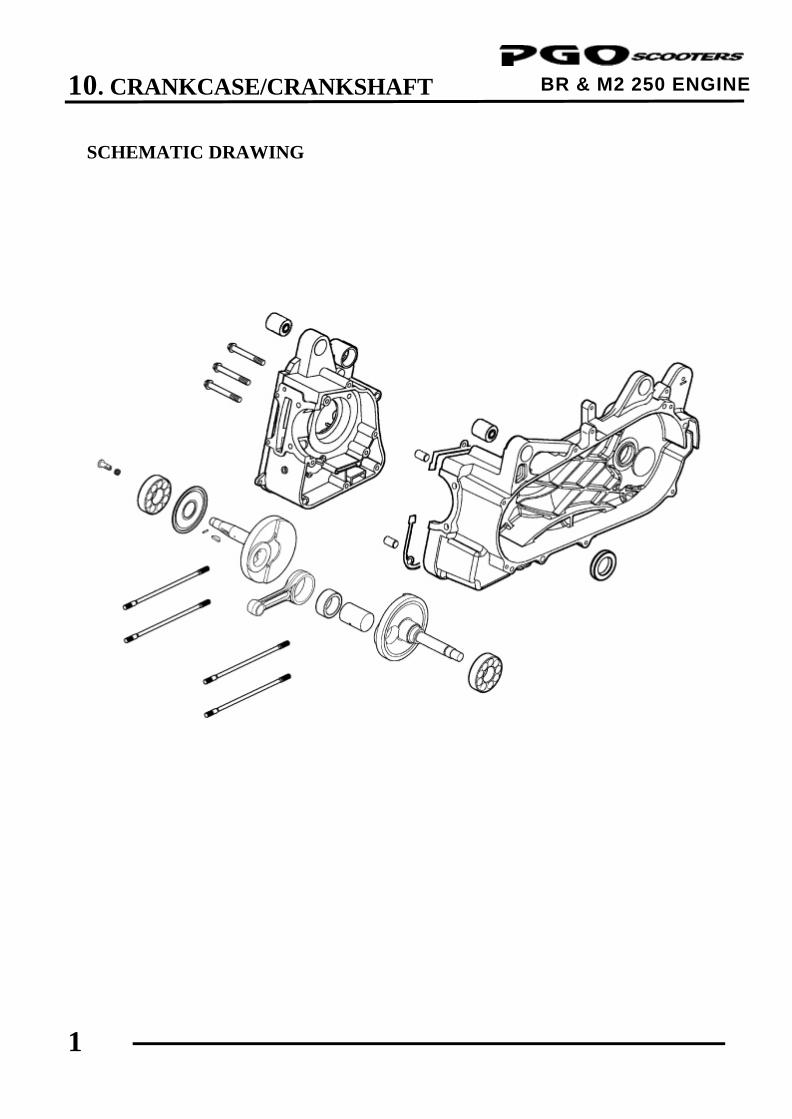
10. CRANKCASE/CRANKSHAFT
1
BR & M2 250 ENGINE
SCHEMATIC DRAWING
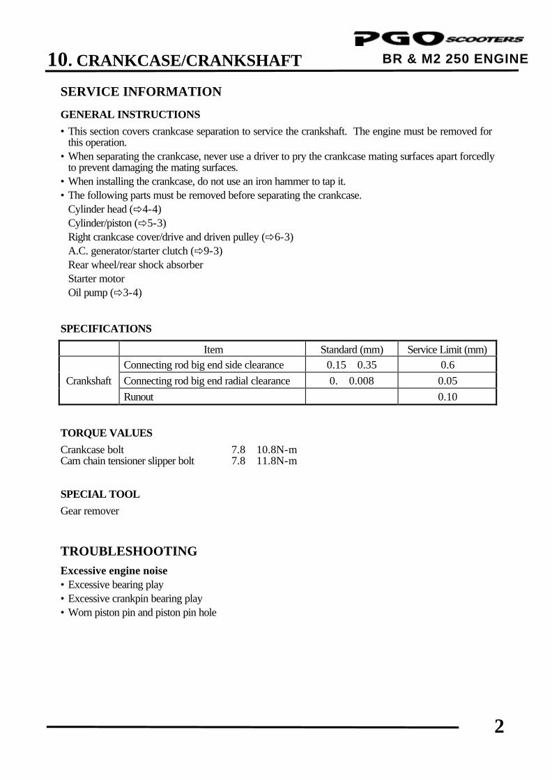
10. CRANKCASE/CRANKSHAFT
2
BR & M2 250 ENGINE SERVICE INFORMATION
GENERAL INSTRUCTIONS
• This section covers crankcase separation to service the crankshaft. The engine must be removed for this operation.
• When separating the crankcase, never use a driver to pry the crankcase mating surfaces apart forcedly to prevent damaging the mating surfaces.
• When installing the crankcase, do not use an iron hammer to tap it. • The following parts must be removed before separating the crankcase.
Cylinder head (ð4-4) Cylinder/piston (ð5-3) Right crankcase cover/drive and driven pulley (ð6-3) A.C. generator/starter clutch (ð9-3) Rear wheel/rear shock absorber Starter motor Oil pump (ð3-4)
SPECIFICATIONS
Item Standard (mm) Service Limit (mm) Connecting rod big end side clearance 0.15∼0.35 0.6 Crankshaft Connecting rod big end radial clearance 0.∼0.008 0.05 Runout 0.10
TORQUE VALUES
Crankcase bolt 7.8∼10.8N-m Cam chain tensioner slipper bolt 7.8∼11.8N-m SPECIAL TOOL
Gear remover TROUBLESHOOTING
Excessive engine noise • Excessive bearing play • Excessive crankpin bearing play • Worn piston pin and piston pin hole
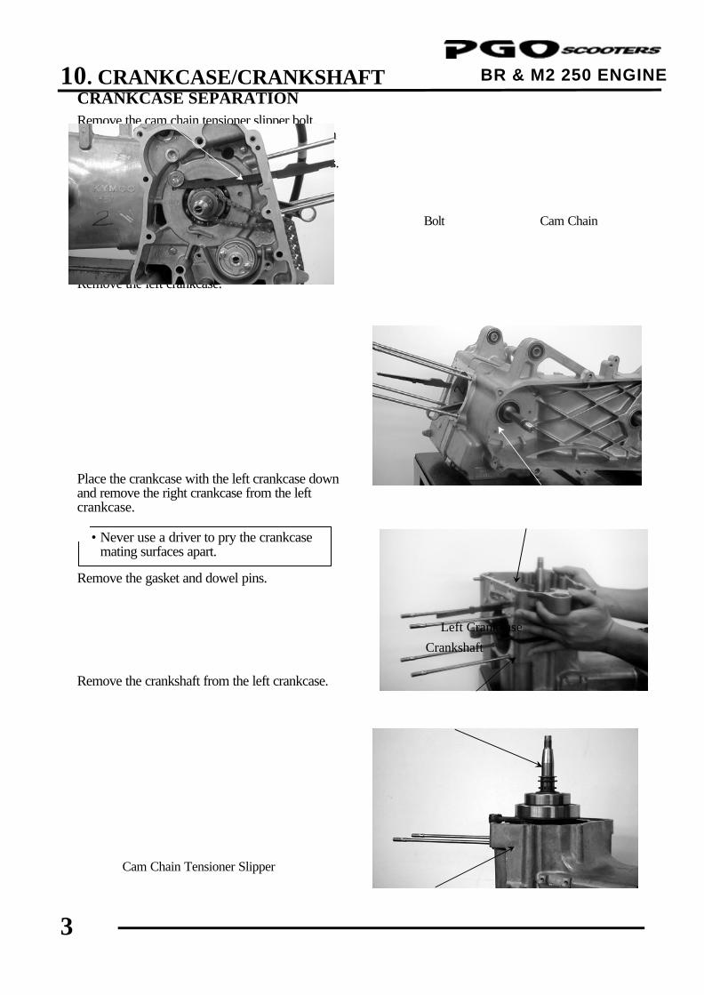
10. CRANKCASE/CRANKSHAFT
3
BR & M2 250 ENGINE CRANKCASE SEPARATION Remove the cam chain tensioner slipper bolt. Remove the cam chain tensioner slipper and cam chain. Remove the three right crankcase attaching bolts. Remove the left crankcase. Place the crankcase with the left crankcase down and remove the right crankcase from the left crankcase. Remove the gasket and dowel pins. Remove the crankshaft from the left crankcase.
Remove the oil seal from the left crankcase.
Cam Chain Tensioner Slipper
Cam Chain Bolt
• Never use a driver to pry the crankcase mating surfaces apart.
*
Left Crankcase
Crankshaft
Right Crankcase
Left Crankcase
Left Crankcase
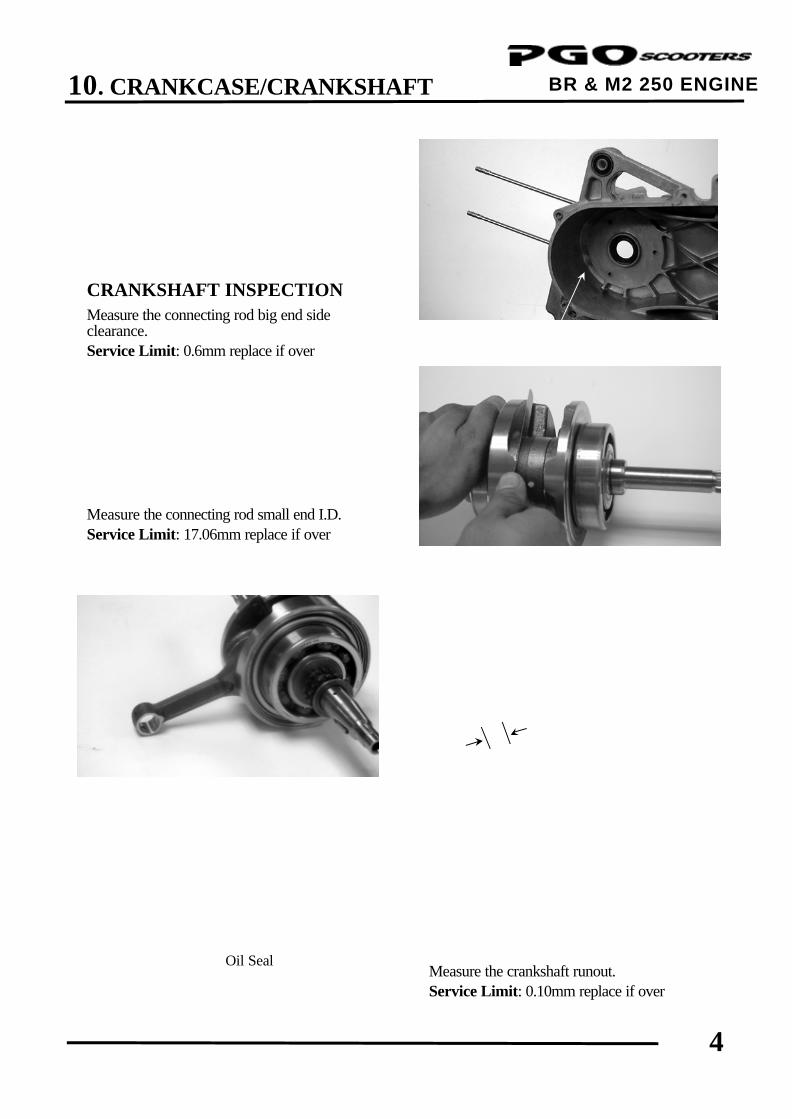
10. CRANKCASE/CRANKSHAFT
4
BR & M2 250 ENGINE CRANKSHAFT INSPECTION Measure the connecting rod big end side clearance. Service Limit: 0.6mm replace if over
Measure the connecting rod small end I.D. Service Limit: 17.06mm replace if over
Measure the crankshaft runout. Service Limit: 0.10mm replace if over
Oil Seal
Left Crankcase
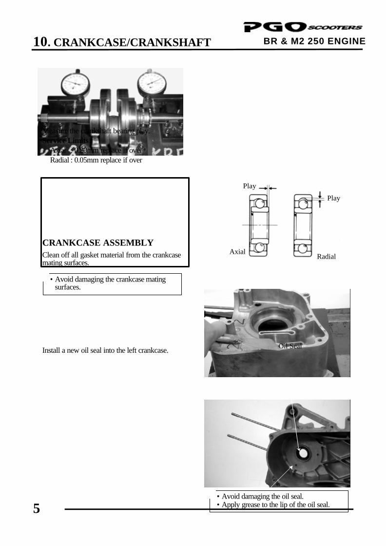
10. CRANKCASE/CRANKSHAFT
5
BR & M2 250 ENGINE
Measure the crankshaft bearing play. Service Limits: Axial : 0.20mm replace if over Radial : 0.05mm replace if over CRANKCASE ASSEMBLY Clean off all gasket material from the crankcase mating surfaces. Install a new oil seal into the left crankcase.
Place the left crankcase down and install the crankshaft into the left crankcase. • Avoid damaging the oil seal.
• Apply grease to the lip of the oil seal. *
Axial
Play
Play
Radial
• Avoid damaging the crankcase mating surfaces.
*
Oil Seal
Left Crankcase
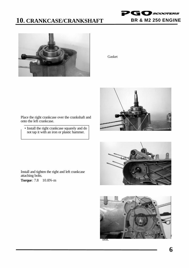
10. CRANKCASE/CRANKSHAFT
6
BR & M2 250 ENGINE Install the two dowel pins and a new gasket.
Place the right crankcase over the crankshaft and onto the left crankcase. Install and tighten the right and left crankcase attaching bolts. Torque: 7.8∼10.8N-m
Install the cam chain. Install the cam chain tensioner slipper. Install and tighten the cam chain tensioner slipper bolt.
Left Crankcase
Gasket
Right Crankcase
Dowel Pins
Bolts
• Install the right crankcase squarely and do not tap it with an iron or plastic hammer.
*
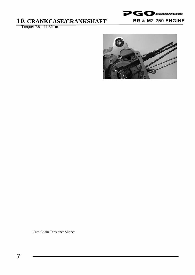
10. CRANKCASE/CRANKSHAFT
7
BR & M2 250 ENGINE Torque: 7.8∼11.8N-m
Cam Chain Tensioner Slipper
Bolt
11. COOLING SYSTEM
0
BR & M2 250 ENGINE
11 __________________________________________________________________________________
__________________________________________________________________________________
__________________________________________________________________________________
__________________________________________________________________________________
__________________________________________________________________________________
COOLING SYSTEM
__________________________________________________________________________________
SCHEMATIC DRAWING --------------------------------------------------- 11- 1
SERVICE INFORMATION ------------------------------------------------- 11- 2
TROUBLESHOOTING------------------------------------------------------- 11- 2
COOLING SYSTEM TESTING-------------------------------------------- 11- 4
RADIATOR--------------------------------------------------------------------- 11- 4
WATER PUMP----------------------------------------------------------------- 11-15
THERMOSTAT ---------------------------------------------------------------- 11-16
11
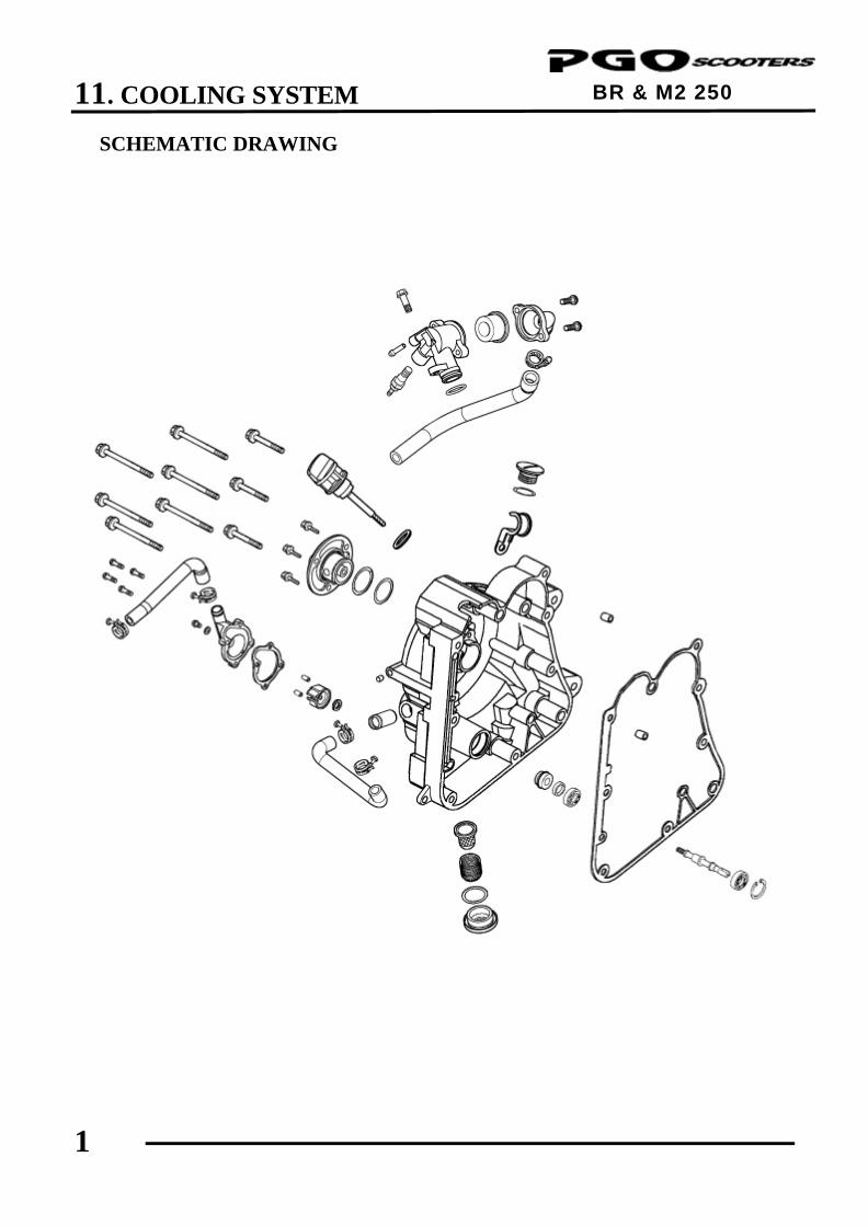
11. COOLING SYSTEM
1
BR & M2 250 ENGINE
SCHEMATIC DRAWING
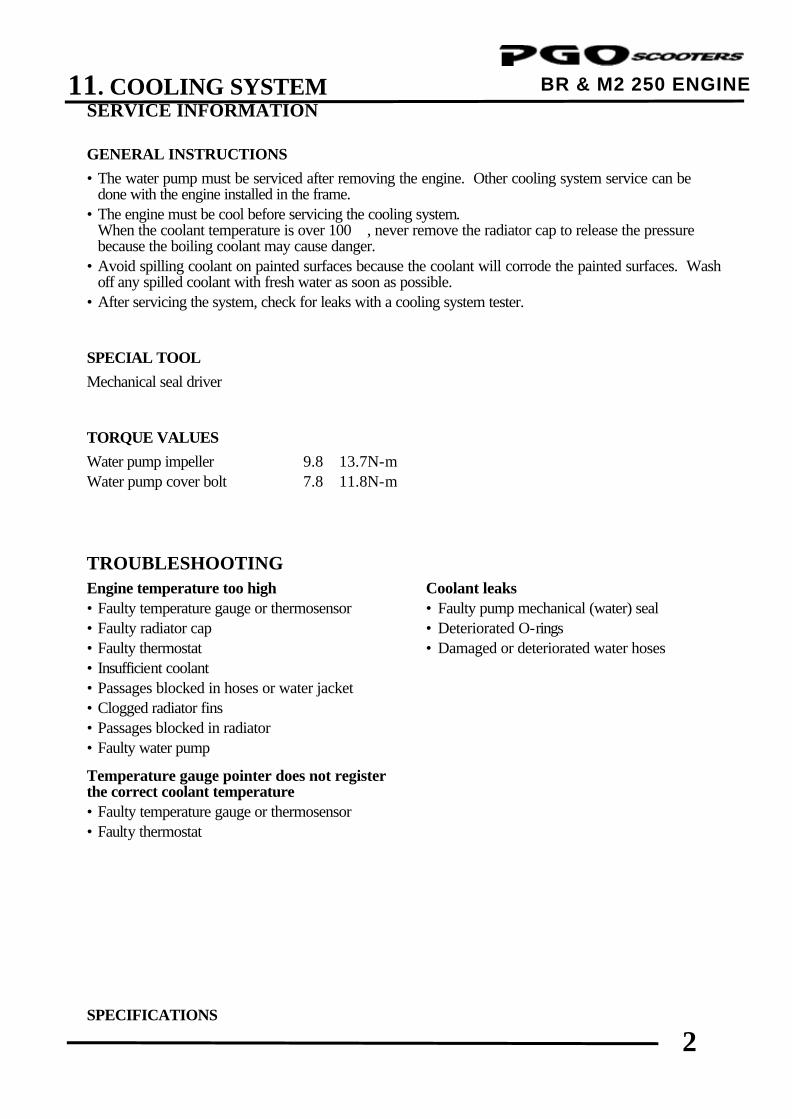
11. COOLING SYSTEM
2
BR & M2 250 ENGINE SERVICE INFORMATION GENERAL INSTRUCTIONS
• The water pump must be serviced after removing the engine. Other cooling system service can be done with the engine installed in the frame.
• The engine must be cool before servicing the cooling system. When the coolant temperature is over 100, never remove the radiator cap to release the pressure
because the boiling coolant may cause danger. • Avoid spilling coolant on painted surfaces because the coolant will corrode the painted surfaces. Wash
off any spilled coolant with fresh water as soon as possible. • After servicing the system, check for leaks with a cooling system tester. SPECIAL TOOL
Mechanical seal driver TORQUE VALUES
Water pump impeller 9.8∼13.7N-m Water pump cover bolt 7.8∼11.8N-m TROUBLESHOOTING Engine temperature too high Coolant leaks • Faulty temperature gauge or thermosensor • Faulty pump mechanical (water) seal • Faulty radiator cap • Deteriorated O-rings • Faulty thermostat • Damaged or deteriorated water hoses • Insufficient coolant • Passages blocked in hoses or water jacket • Clogged radiator fins • Passages blocked in radiator • Faulty water pump
Temperature gauge pointer does not register the correct coolant temperature • Faulty temperature gauge or thermosensor • Faulty thermostat
SPECIFICATIONS
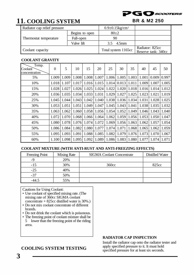
11. COOLING SYSTEM
3
BR & M2 250 ENGINE Radiator cap relief pressure 0.9±0.15kg/cm²
Begins to open 80±2 Thermostat temperature Full-open 90 Valve lift 3.5∼4.5mm Coolant capacity Total system 1165cc Radiator: 825cc
Reserve tank: 340cc
COOLANT GRAVITY Temp.
Coolant concentration
0 5 10 15 20 25 30 35 40 45 50
5% 1.009 1.009 1.008 1.008 1.007 1.006 1.005 1.003 1.001 0.009 0.997 10% 1.018 1.107 1.017 1.016 1.015 1.014 0.013 1.011 1.009 1.007 1.005 15% 1.028 1.027 1.026 1.025 1.024 1.022 1.020 1.018 1.016 1.014 1.012 20% 1.036 1.035 1.034 1.033 1.031 1.029 1.027 1.025 1.023 1.021 1.019 25% 1.045 1.044 1.043 1.042 1.040 1.038 1.036 1.034 1.031 1.028 1.025 30% 1.053 1.051 1.051 1.049 1.047 1.045 1.043 1.041 1.038 1.035 1.032 35% 1.063 1.062 1.060 1.058 1.056 1.054 1.052 1.049 1.046 1.043 1.040 40% 1.072 1.070 1.068 1.066 1.064 1.062 1.059 1.056 1.053 1.050 1.047 45% 1.080 1.078 1.076 1.074 1.072 1.069 1.056 1.063 1.062 1.057 1.054 50% 1.086 1.084 1.082 1.080 1.077 1.074 1.071 1.068 1.065 1.062 1.059 55% 1.095 1.093 1.091 1.088 1.085 1.082 1.079 1.076 1.073 1.070 1.067 60% 1.100 1.098 1.095 1.092 1.089 1.086 1.083 1.080 1.077 1.074 1.071
COOLANT MIXTURE (WITH ANTI-RUST AND ANTI-FREEZING EFFECTS) Freezing Point Mixing Rate SIGMA Coolant Concentrate Distilled Water -9 20% -15 30% 360cc 825cc -25 40% -37 50% -44.5 55%
COOLING SYSTEM TESTING
RADIATOR CAP INSPECTION Install the radiator cap onto the radiator tester and apply specified pressure to it. It must hold specified pressure for at least six seconds.
Cautions for Using Coolant: • Use coolant of specified mixing rate. (The
mixing rate of 360cc SIGMA coolant concentrate + 825cc distilled water is 30%.)
• Do not mix coolant concentrate of different brands.
• Do not drink the coolant which is poisonous. • The freezing point of coolant mixture shall be
5lower than the freezing point of the riding area.
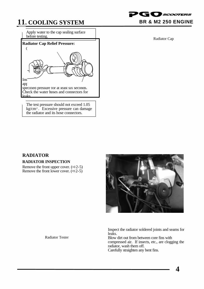
11. COOLING SYSTEM
4
BR & M2 250 ENGINE
Radiator Cap Relief Pressure: 0.9±0.15kg/cm² Install the radiator tester onto the radiator and apply specified pressure to it. It must hold specified pressure for at least six seconds. Check the water hoses and connectors for leaks. RADIATOR
RADIATOR INSPECTION Remove the front upper cover. (ð2-5) Remove the front lower cover. (ð2-5)
Inspect the radiator soldered joints and seams for leaks. Blow dirt out from between core fins with compressed air. If insects, etc., are clogging the radiator, wash them off. Carefully straighten any bent fins.
The test pressure should not exceed 1.05 kg/cm². Excessive pressure can damage the radiator and its hose connectors.
*
Apply water to the cap sealing surface before testing.
*
Radiator Cap
Radiator Tester
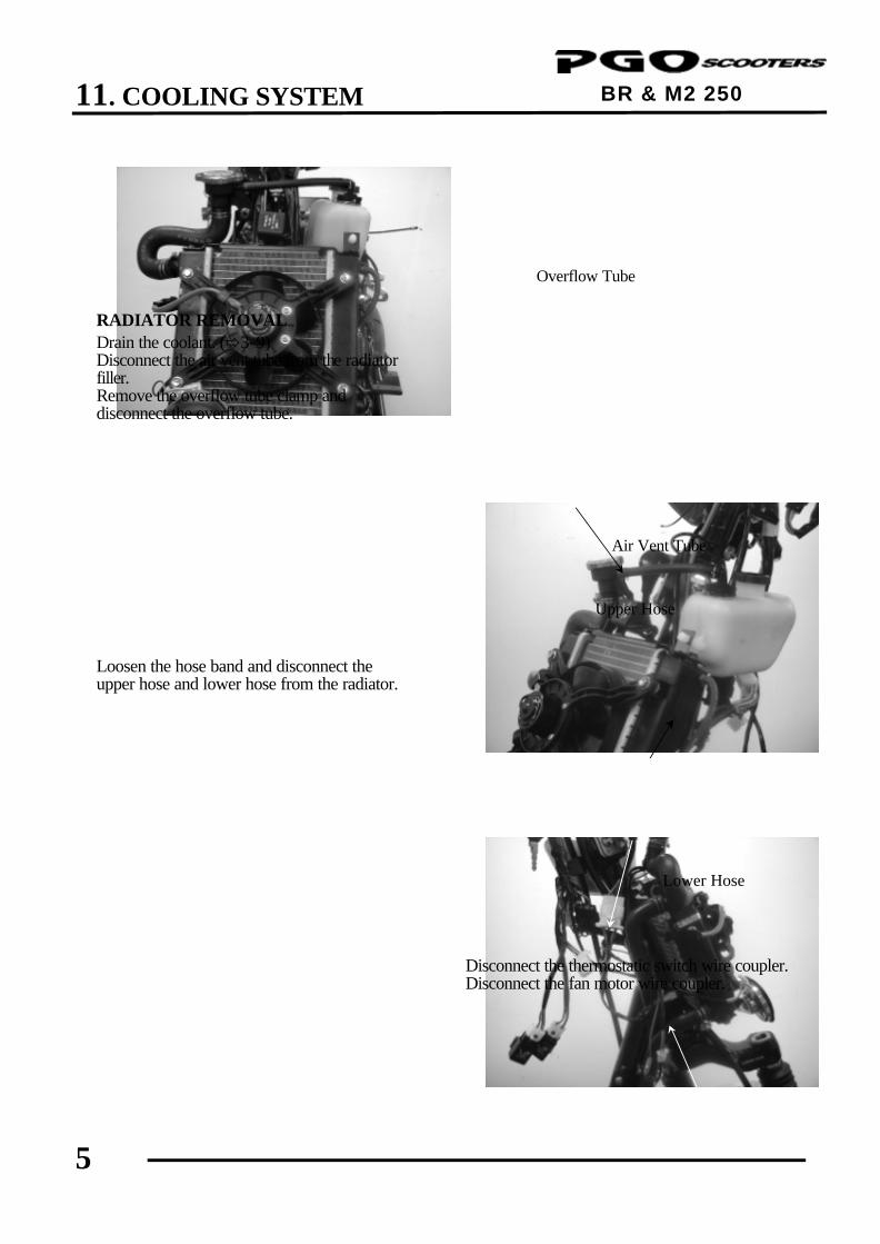
11. COOLING SYSTEM
5
BR & M2 250 ENGINE
RADIATOR REMOVAL Drain the coolant. (ð3-9) Disconnect the air vent tube from the radiator filler. Remove the overflow tube clamp and disconnect the overflow tube. Loosen the hose band and disconnect the upper hose and lower hose from the radiator.
Disconnect the thermostatic switch wire coupler. Disconnect the fan motor wire coupler.
Air Vent Tube
Lower Hose
Upper Hose
Overflow Tube
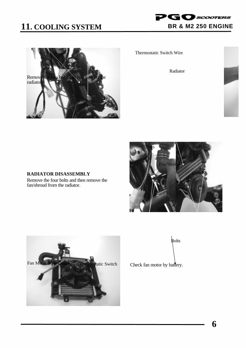
11. COOLING SYSTEM
6
BR & M2 250 ENGINE
Remove the two bolts and two nuts on the radiator.
RADIATOR DISASSEMBLY Remove the four bolts and then remove the fan/shroud from the radiator.
Check fan motor by battery.
Fan/Shroud
Radiator
Bolts
Thermostatic Switch Wire
Fan Motor Wire Coupler
Bolts
Thermostatic Switch
Nuts
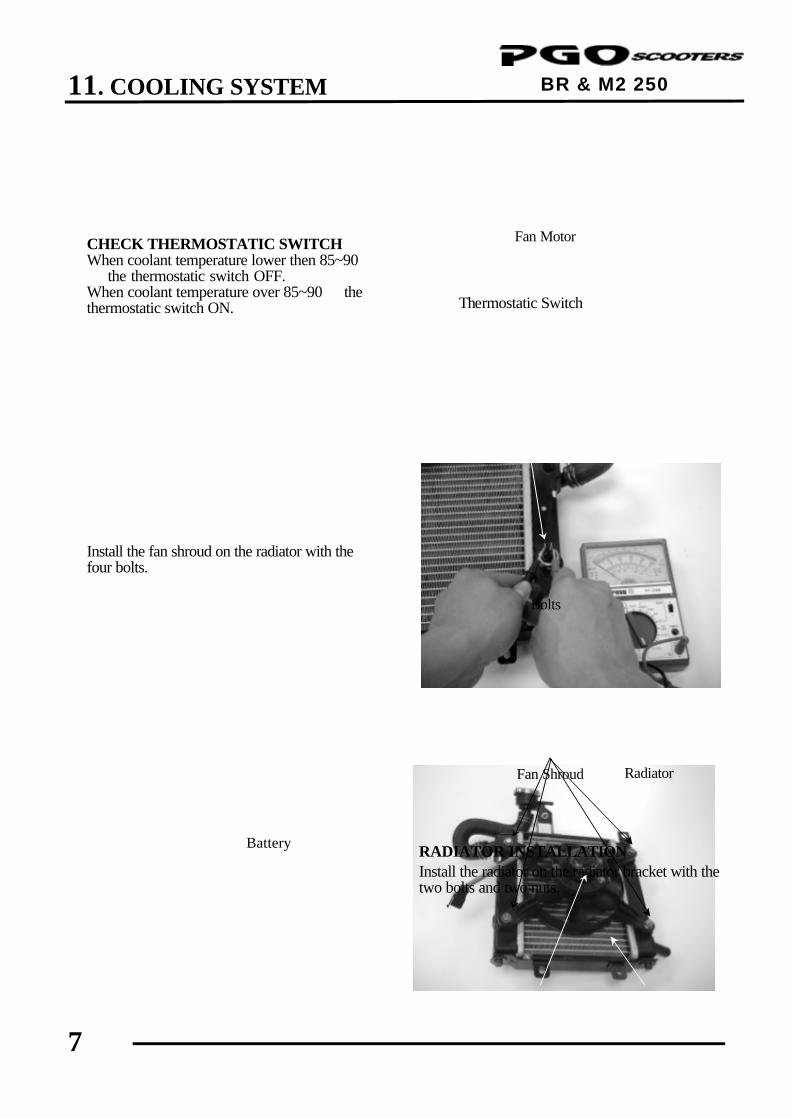
11. COOLING SYSTEM
7
BR & M2 250 ENGINE
CHECK THERMOSTATIC SWITCH When coolant temperature lower then 85~90 the thermostatic switch OFF. When coolant temperature over 85~90 the thermostatic switch ON. Install the fan shroud on the radiator with the four bolts.
RADIATOR INSTALLATION Install the radiator on the radiator bracket with the two bolts and two nuts.
Radiator
Thermostatic Switch
Bolts
Fan Motor
Battery
Fan Shroud
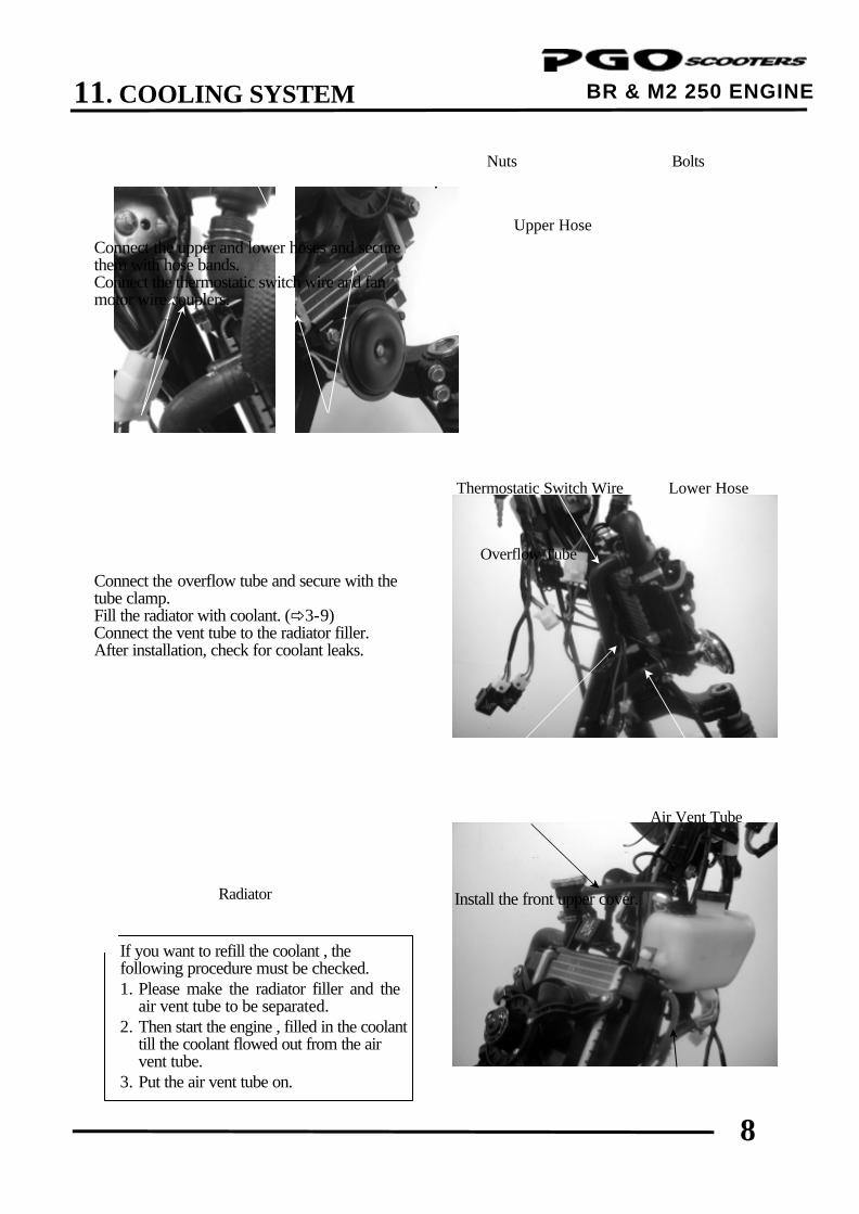
11. COOLING SYSTEM
8
BR & M2 250 ENGINE
Connect the upper and lower hoses and secure them with hose bands. Connect the thermostatic switch wire and fan motor wire couplers. Connect the overflow tube and secure with the tube clamp. Fill the radiator with coolant. (ð3-9) Connect the vent tube to the radiator filler. After installation, check for coolant leaks.
.
Install the front upper cover.
Air Vent Tube
Radiator
Upper Hose
Overflow Tube
Lower Hose
Bolts
Thermostatic Switch Wire
Nuts
If you want to refill the coolant , the following procedure must be checked. 1. Please make the radiator filler and the
air vent tube to be separated. 2. Then start the engine , filled in the coolant
till the coolant flowed out from the air vent tube.
3. Put the air vent tube on.
*
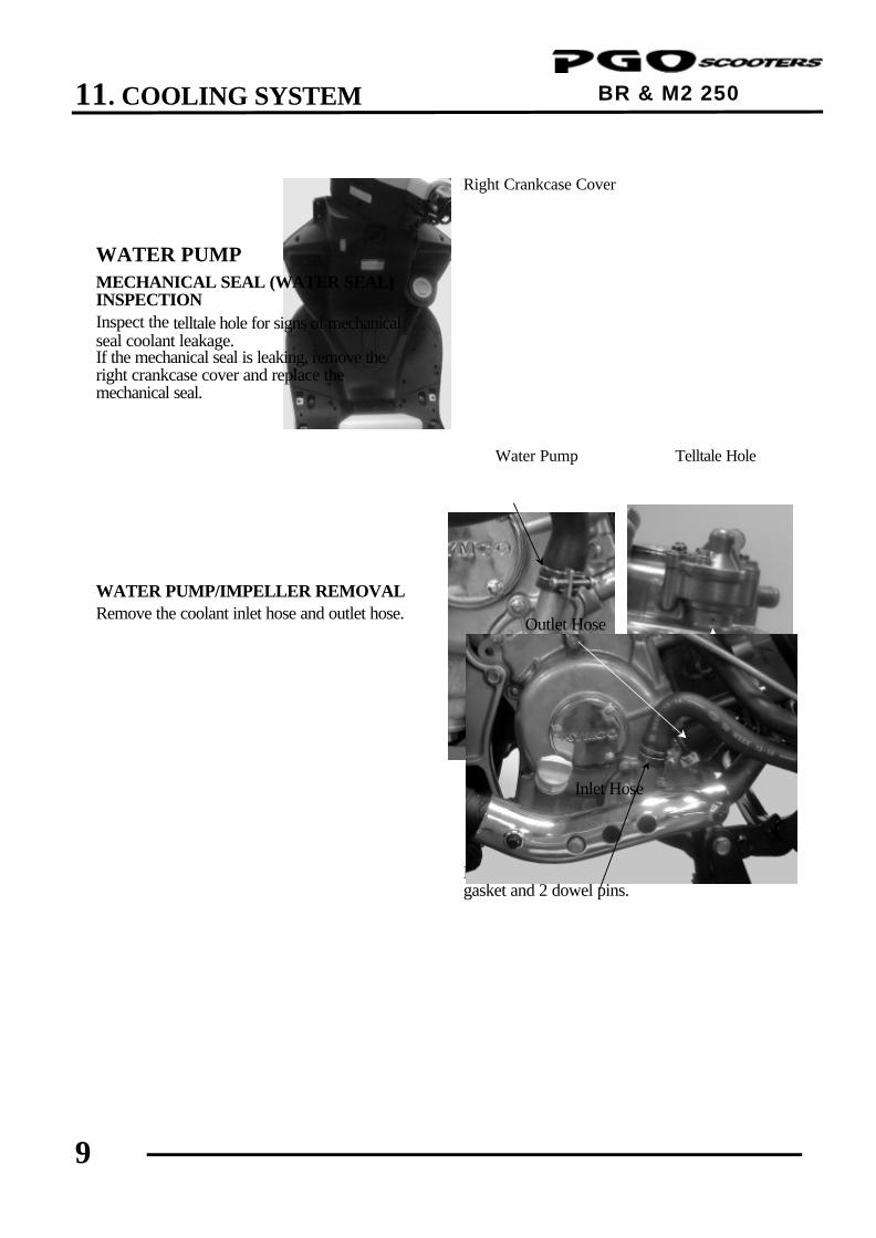
11. COOLING SYSTEM
9
BR & M2 250 ENGINE
WATER PUMP MECHANICAL SEAL (WATER SEAL) INSPECTION Inspect the telltale hole for signs of mechanical seal coolant leakage. If the mechanical seal is leaking, remove the right crankcase cover and replace the mechanical seal. WATER PUMP/IMPELLER REMOVAL Remove the coolant inlet hose and outlet hose.
Remove the four bolts and the water pump cover, gasket and 2 dowel pins.
Right Crankcase Cover
Telltale Hole Water Pump
Outlet Hose
Inlet Hose
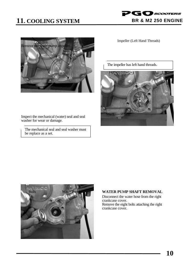
11. COOLING SYSTEM
10
BR & M2 250 ENGINE
Remove the water pump impeller. Inspect the mechanical (water) seal and seal washer for wear or damage.
WATER PUMP SHAFT REMOVAL Disconnect the water hose from the right crankcase cover. Remove the eight bolts attaching the right crankcase cover.
Impeller (Left Hand Threads)
Water Pump Cover Bolts
The mechanical seal and seal washer must be replace as a set.
*
The impeller has left hand threads. *
Mechanical Seal
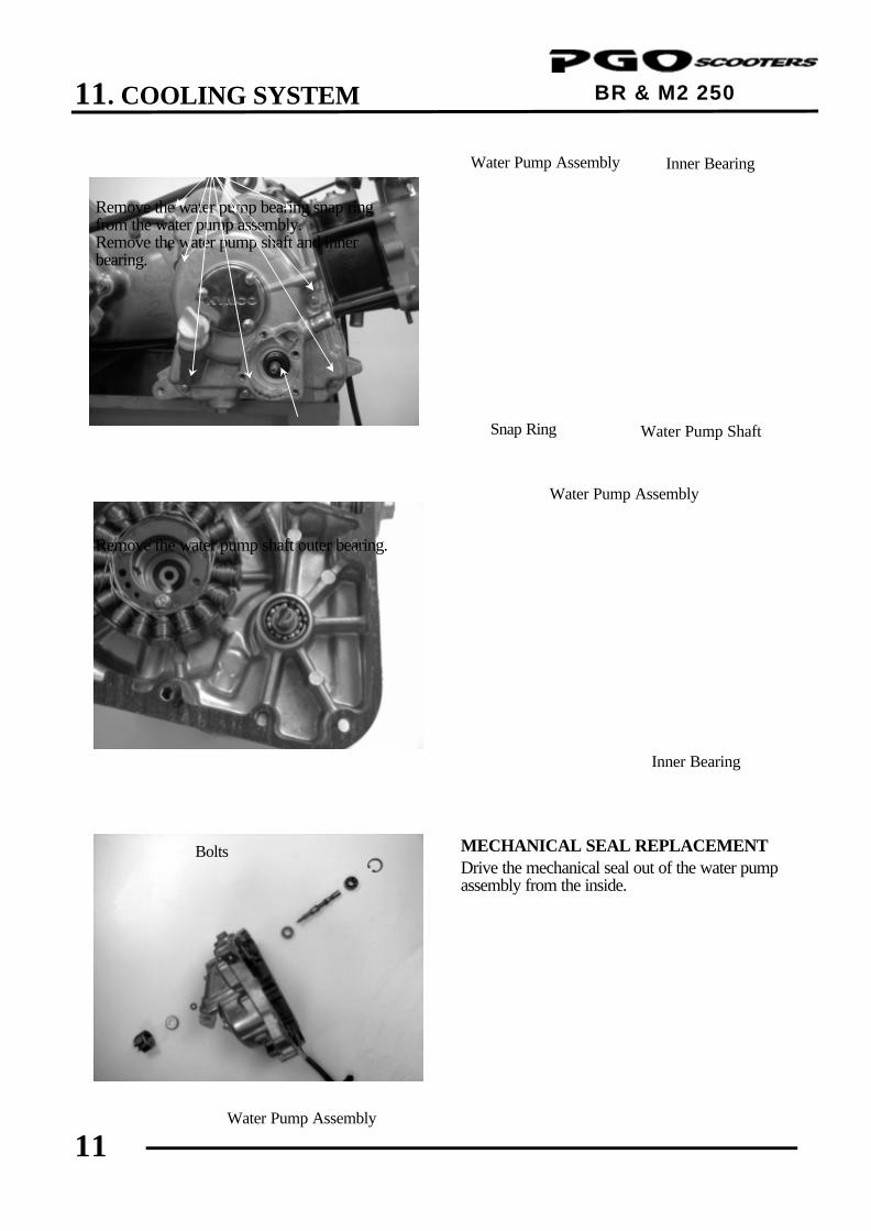
11. COOLING SYSTEM
11
BR & M2 250 ENGINE
Remove the water pump bearing snap ring from the water pump assembly. Remove the water pump shaft and inner bearing. Remove the water pump shaft outer bearing.
MECHANICAL SEAL REPLACEMENT Drive the mechanical seal out of the water pump assembly from the inside.
Inner Bearing
Snap Ring
Water Pump Assembly
Bolts
Inner Bearing
Water Pump Assembly
Water Pump Shaft
Water Pump Assembly
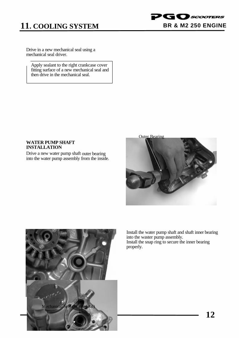
11. COOLING SYSTEM
12
BR & M2 250 ENGINE
Water Pump Assembly
Drive in a new mechanical seal using a mechanical seal driver. WATER PUMP SHAFT INSTALLATION Drive a new water pump shaft outer bearing into the water pump assembly from the inside.
Install the water pump shaft and shaft inner bearing into the waster pump assembly. Install the snap ring to secure the inner bearing properly.
Apply sealant to the right crankcase cover fitting surface of a new mechanical seal and then drive in the mechanical seal.
*
Outer Bearing
Mechanical Seal (Water Seal)
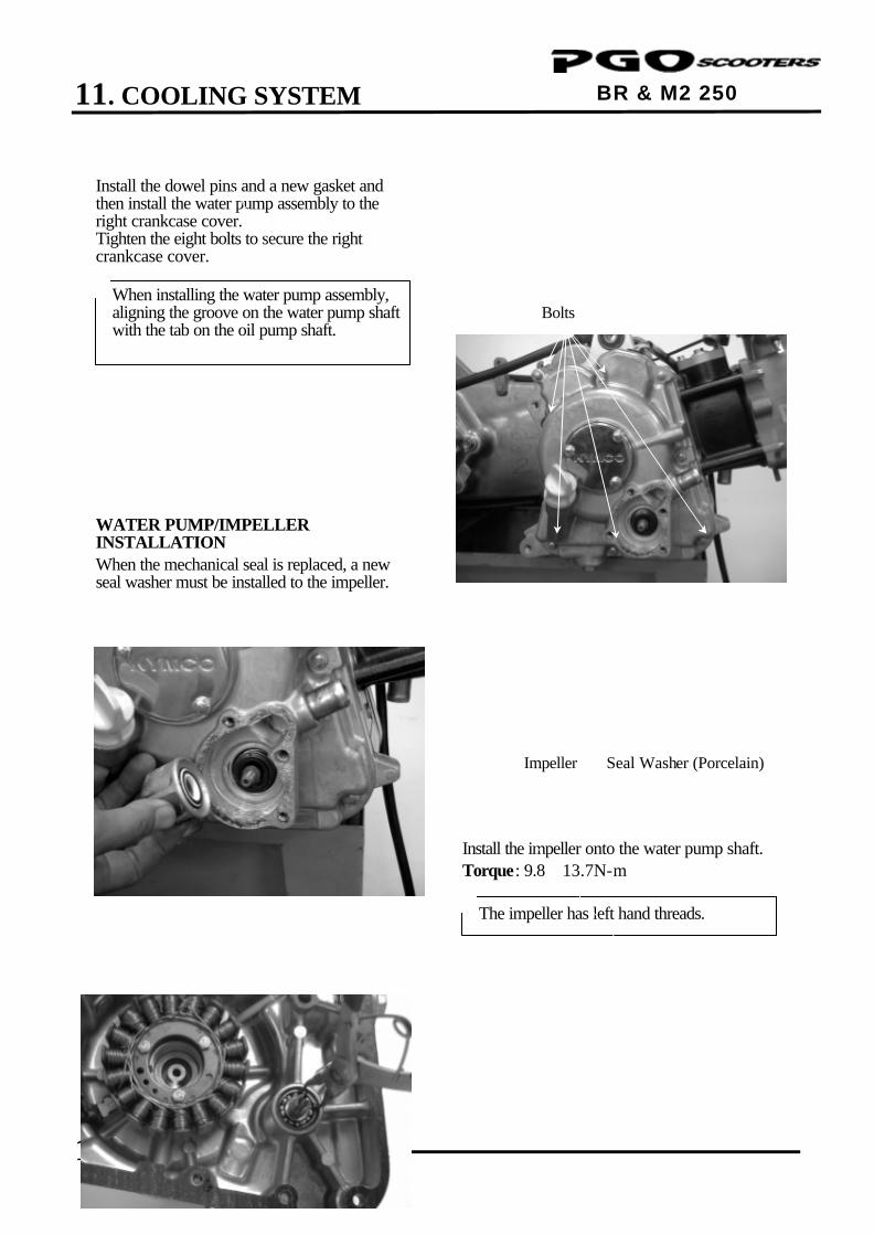
11. COOLING SYSTEM
13
BR & M2 250 ENGINE
Install the dowel pins and a new gasket and then install the water pump assembly to the right crankcase cover. Tighten the eight bolts to secure the right crankcase cover. WATER PUMP/IMPELLER INSTALLATION When the mechanical seal is replaced, a new seal washer must be installed to the impeller.
Install the impeller onto the water pump shaft. Torque: 9.8∼13.7N-m
When installing the water pump assembly, aligning the groove on the water pump shaft with the tab on the oil pump shaft.
*
The impeller has left hand threads. *
Seal Washer (Porcelain) Impeller
Inner Bearing
Snap Ring Water Pump Shaft
Bolts
Water Pump Assembly
Mechanical Seal
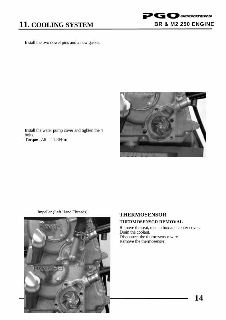
11. COOLING SYSTEM
14
BR & M2 250 ENGINE Install the two dowel pins and a new gasket. Install the water pump cover and tighten the 4 bolts. Torque: 7.8∼11.8N-m
THERMOSENSOR
THERMOSENSOR REMOVAL Remove the seat, met-in box and center cover. Drain the coolant. Disconnect the thermosensor wire. Remove the thermosensor.
Impeller (Left Hand Threads)
Water Pump Cover
Dowel Pins
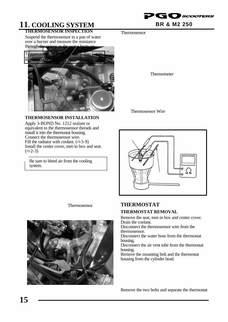
11. COOLING SYSTEM
15
BR & M2 250 ENGINE
THERMOSENSOR INSPECTION Suspend the thermosensor in a pan of water over a burner and measure the resistance through the sensor as the water heats up.
Temperature() 50 80 100 120 Resistance(Ω) 154 52 27 16
THERMOSENSOR INSTALLATION Apply 3-BOND No. 1212 sealant or equivalent to the thermosensor threads and install it into the thermostat housing. Connect the thermosensor wire. Fill the radiator with coolant. (ð3-9) Install the center cover, met-in box and seat. (ð2-3)
THERMOSTAT
THERMOSTAT REMOVAL Remove the seat, met-in box and center cover. Drain the coolant. Disconnect the thermosensor wire from the thermosensor. Disconnect the water hose from the thermostat housing. Disconnect the air vent tube from the thermostat housing. Remove the mounting bolt and the thermostat housing from the cylinder head. Remove the two bolts and separate the thermostat
Be sure to bleed air from the cooling system.
*
Thermosensor
Thermosensor Wire
Thermosensor Wire
Thermosensor
Thermometer
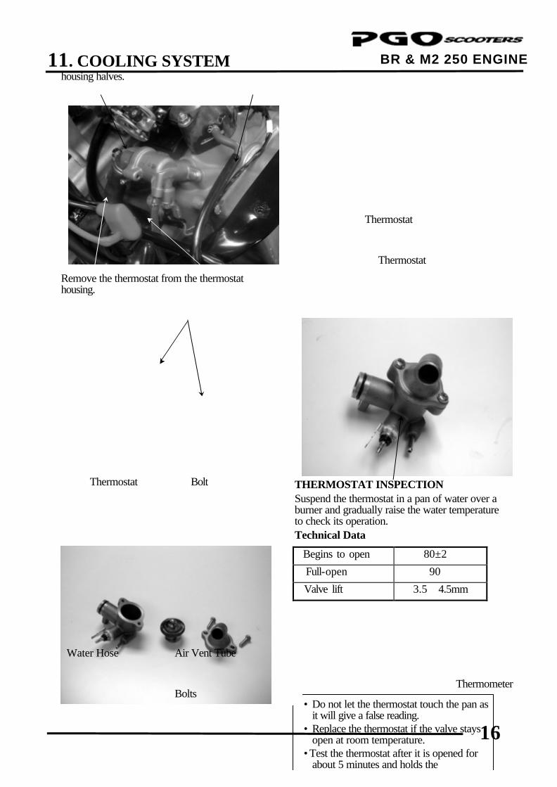
11. COOLING SYSTEM
16
BR & M2 250 ENGINE
• Do not let the thermostat touch the pan as it will give a false reading.
• Replace the thermostat if the valve stays open at room temperature.
•Test the thermostat after it is opened for about 5 minutes and holds the temperature at 70 .
*Thermometer
housing halves. Remove the thermostat from the thermostat housing.
THERMOSTAT INSPECTION Suspend the thermostat in a pan of water over a burner and gradually raise the water temperature to check its operation. Technical Data
Begins to open 80±2
Full-open 90
Valve lift 3.5∼4.5mm
Thermostat
Thermostat
Bolts
Thermostat
Water Hose Air Vent Tube
Bolt
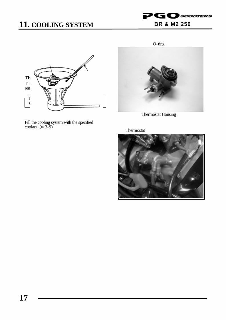
11. COOLING SYSTEM
17
BR & M2 250 ENGINE
THERMOSTAT INSTALLATION The installation sequence is the reverse of removal. Fill the cooling system with the specified coolant. (ð3-9)
Replace the O-ring with a new one and apply grease to it.
*
O-ring
Thermostat Housing
Thermostat
Related Documents