bq27520-G4 System-Side Impedance Track™ Fuel Gauge With Integrated LDO Technical Reference Manual Literature Number: SLUUA35 August 2013

Welcome message from author
This document is posted to help you gain knowledge. Please leave a comment to let me know what you think about it! Share it to your friends and learn new things together.
Transcript

bq27520-G4 System-Side Impedance Track™Fuel Gauge With Integrated LDO
Technical Reference Manual
Literature Number: SLUUA35August 2013

Contents
Preface ....................................................................................................................................... 51 General Description ............................................................................................................. 62 Standard Data Commands .................................................................................................... 7
2.1 Control( ): 0x00 and 0x01 ................................................................................................. 82.1.1 CONTROL_STATUS: 0x0000 .................................................................................... 92.1.2 DEVICE_TYPE: 0x0001 .......................................................................................... 92.1.3 FW_VERSION: 0x0002 ........................................................................................... 92.1.4 PREV_MACWRITE: 0x0007 ...................................................................................... 92.1.5 CHEM_ID: 0x0008 ................................................................................................. 92.1.6 OCV_CMD: 0x000C .............................................................................................. 102.1.7 BAT_INSERT: 0x000D .......................................................................................... 102.1.8 BAT_REMOVE: 0x000E ......................................................................................... 102.1.9 SET_HIBERNATE: 0x0011 ..................................................................................... 102.1.10 CLEAR_HIBERNATE: 0x0012 ................................................................................. 102.1.11 SET_SNOOZE: 0x0013 ........................................................................................ 102.1.12 CLEAR_SNOOZE: 0x0014 ..................................................................................... 102.1.13 DF_VERSION: 0x001F ......................................................................................... 102.1.14 SEALED: 0x0020 ................................................................................................ 102.1.15 IT_ENABLE: 0x0021 ............................................................................................ 112.1.16 RESET: 0x0041 ................................................................................................. 11
2.2 AtRate( ): 0x02 and 0x03 ................................................................................................ 112.3 AtRateTimeToEmpty( ): 0x04 and 0x05 ............................................................................... 112.4 Temperature( ): 0x06 and 0x07 ......................................................................................... 112.5 Voltage( ): 0x08 and 0x09 ............................................................................................... 112.6 Flags( ): 0x0A and 0x0B ................................................................................................. 122.7 NominalAvailableCapacity( ): 0x0C and 0x0D ...................................................................... 122.8 FullAvailableCapacity( ): 0x0E and 0x0F ............................................................................. 122.9 RemainingCapacity( ): 0x10 and 0x11 ................................................................................ 122.10 FullChargeCapacity( ): 0x12 and 0x13 ................................................................................ 132.11 AverageCurrent( ): 0x14 and 0x15 ..................................................................................... 132.12 TimeToEmpty( ): 0x16 and 0x17 ....................................................................................... 132.13 StandbyCurrent( ): 0x18 and 0x19 ..................................................................................... 132.14 StandbyTimeToEmpty( ): 0x1A and 0x1B ............................................................................ 132.15 StateofHealth( ): 0x1C and 0x1D ....................................................................................... 132.16 CycleCount( ): 0x1E and 0x1F .......................................................................................... 142.17 StateOfCharge( ): 0x20 and 0x21 ...................................................................................... 142.18 InstantaneousCurrent( ): 0x22 and 0x23 ............................................................................. 142.19 InternalTemperature( ): 0x28 and 0x29 ............................................................................... 142.20 ResistanceScale( ): 0x2A and 0x2B ................................................................................... 142.21 OperationConfiguration( ): 0x2C and 0x2D .......................................................................... 142.22 DesignCapacity( ): 0x2E and 0x2F .................................................................................... 142.23 UnfilteredRM( ): 0x6C and 0x6D ....................................................................................... 142.24 FilteredRM( ): 0x6E and 0x6F ........................................................................................... 142.25 UnfilteredFCC( ): 0x70 and 0x71 ....................................................................................... 142.26 FilteredFCC( ): 0x72 and 0x73 .......................................................................................... 15
2 Contents SLUUA35–August 2013Submit Documentation Feedback
Copyright © 2013, Texas Instruments Incorporated

www.ti.com
2.27 TrueSOC( ): 0x74 and 0x75 ............................................................................................. 15
3 Extended Data Commands ................................................................................................. 163.1 DataFlashClass( ): 0x3E ................................................................................................. 163.2 DataFlashBlock( ): 0x3F ................................................................................................. 163.3 BlockData( ): 0x40 to 0x5F .............................................................................................. 163.4 BlockDataChecksum( ): 0x60 .......................................................................................... 173.5 BlockDataControl( ): 0x61 .............................................................................................. 173.6 ApplicationStatus( ): 0x6A .............................................................................................. 17
4 Data Flash Interface ........................................................................................................... 184.1 Accessing The Data Flash ............................................................................................... 184.2 Manufacturer Information Block ......................................................................................... 194.3 Device Access Modes .................................................................................................... 194.4 Sealing and Unsealing Data Flash ...................................................................................... 194.5 Data Flash Summary ...................................................................................................... 204.6 Data Flash Parameter Update Example ................................................................................ 27
4.6.1 Modify WRTEMP of OpConfig B Register .................................................................... 28
5 Functional Description ....................................................................................................... 305.1 Impedance Track™ Variables ........................................................................................... 30
5.1.1 Load Mode ........................................................................................................ 305.1.2 Load Select ........................................................................................................ 305.1.3 Reserve Cap-mAh, Reserve Cap-mWh/cWh ................................................................. 315.1.4 Design Energy Scale ............................................................................................. 315.1.5 Dsg Current Threshold ........................................................................................... 315.1.6 Chg Current Threshold .......................................................................................... 315.1.7 Quit Current, Dsg Relax Time, Chg Relax Time, and Quit Relax Time ................................... 315.1.8 Qmax Cell 0 and Qmax Cell 1 .................................................................................. 325.1.9 Update Status 0 and Update Status 1 ......................................................................... 325.1.10 Avg I Last Run ................................................................................................... 325.1.11 Avg P Last Run .................................................................................................. 325.1.12 Delta Voltage ..................................................................................................... 325.1.13 Default Ra and Ra Tables ...................................................................................... 325.1.14 Fast Resistance Scaling ........................................................................................ 335.1.15 Fast Qmax Update .............................................................................................. 335.1.16 SOC Smoothing ................................................................................................. 345.1.17 Flash Updates ................................................................................................... 34
5.2 Device Configuration ...................................................................................................... 355.2.1 Operation Configuration (Op Config) Register ................................................................ 355.2.2 Operation Configuration B (OpConfig B) Register ........................................................... 365.2.3 Operation Configuration C (OpConfig C) Register ........................................................... 365.2.4 Operation Configuration D (OpConfig D) Register ........................................................... 375.2.5 Operation Configuration E (OpConfig E) Register ........................................................... 37
5.3 External Pin Functions .................................................................................................... 385.3.1 Pin Function Code (PFC) Descriptions ........................................................................ 385.3.2 BAT_LOW Pin .................................................................................................... 385.3.3 Battery Presence Detection Using the BI/TOUT Pin ......................................................... 385.3.4 SOC_INT Pin Behavior .......................................................................................... 395.3.5 Power Path Control With the BAT_GD Pin ................................................................... 395.3.6 Wake-Up Comparator ............................................................................................ 405.3.7 Autocalibration .................................................................................................... 40
5.4 Temperature Measurement .............................................................................................. 415.4.1 Overtemperature Indication ..................................................................................... 41
5.5 Charging and Charge—Termination Indication ........................................................................ 425.5.1 Detecting Charge Termination .................................................................................. 42
3SLUUA35–August 2013 ContentsSubmit Documentation Feedback
Copyright © 2013, Texas Instruments Incorporated

www.ti.com
5.5.2 Charge Inhibit and Suspend .................................................................................... 425.6 Power Modes .............................................................................................................. 43
5.6.1 BAT INSERT CHECK Mode .................................................................................... 465.6.2 NORMAL Mode ................................................................................................... 465.6.3 SLEEP Mode ...................................................................................................... 465.6.4 SNOOZE Mode ................................................................................................... 465.6.5 HIBERNATE Mode ............................................................................................... 47
5.7 Application-Specific Information ......................................................................................... 475.7.1 Battery Profile Storage and Selection ......................................................................... 475.7.2 First OCV and Impedance Measurement ..................................................................... 48
5.8 Additional Data Flash Parameter Descriptions ........................................................................ 485.8.1 TCA Set % ......................................................................................................... 485.8.2 TCA Clear % ...................................................................................................... 485.8.3 FC Set % .......................................................................................................... 485.8.4 FC Clear % ........................................................................................................ 485.8.5 DOD at EOC Delta Temperature ............................................................................... 495.8.6 Default Temperature ............................................................................................. 495.8.7 Device Name ...................................................................................................... 495.8.8 Data Flash Version ............................................................................................... 495.8.9 SOC1 Set Threshold ............................................................................................. 495.8.10 SOC1 Clear Threshold ......................................................................................... 495.8.11 Final Voltage and Final Volt Time ............................................................................. 495.8.12 Def Avg I Last Run and Def Avg P Last Run ................................................................ 495.8.13 Max Res Factor .................................................................................................. 495.8.14 Min Res Factor .................................................................................................. 505.8.15 Ra Filter ........................................................................................................... 505.8.16 ResRelax Time .................................................................................................. 505.8.17 Max Sim Rate, Min Sim Rate .................................................................................. 505.8.18 Transient Factor Charge and Discharge ..................................................................... 505.8.19 Max IR Correct ................................................................................................... 505.8.20 Thermal Modeling ............................................................................................... 505.8.21 Cell 0 and 1 V at Chg Term .................................................................................... 515.8.22 Calibration, Data, ID = 104 ..................................................................................... 51
6 Communications ............................................................................................................... 536.1 I2C Interface ................................................................................................................ 536.2 I2C Time Out ............................................................................................................... 536.3 I2C Command Waiting Time .............................................................................................. 546.4 I2C Clock Stretching ....................................................................................................... 54
7 Reference Schematic ......................................................................................................... 55A Open-Circuit Voltage Measurement Background ................................................................... 57
A.1 Background ................................................................................................................. 57A.1.1 OCV Qualification and Calculation ............................................................................. 57A.1.2 OCV Calculation Assumption ................................................................................... 57A.1.3 OCV Timing ....................................................................................................... 57
A.2 OCV Timing and OCV_CMD Use Recommendations ................................................................ 59A.2.1 ACTIVE Mode (Fuel Gauge is not in SLEEP Mode) ......................................................... 59A.2.2 SLEEP Mode ...................................................................................................... 59A.2.3 Initial OCV – POR ................................................................................................ 59
B Glossary ........................................................................................................................... 61
4 Contents SLUUA35–August 2013Submit Documentation Feedback
Copyright © 2013, Texas Instruments Incorporated

Read This FirstSLUUA35–August 2013
Preface
This document is a detailed Technical Reference Manual (TRM) for using and configuring the bq27520-G4battery fuel gauge. This TRM document is intended to complement but not supersede any informationcontained in the separate bq27520-G4 datasheet.
Refer to the bq27520-G4 Datasheet (SLUSB20).
Formatting conventions used in this document:
Information Type Formatting Convention ExampleCommands Italics with parentheses and no breaking spaces RemainingCapacity( ) commandData Flash Italics, bold, and breaking spaces Design Capacity dataRegister bits and flags Brackets and italics [TDA] bitData Flash bits Brackets, italics, and bold [LED1] bitModes and states ALL CAPITALS UNSEALED mode
Related Documentation from Texas InstrumentsTo obtain a copy of any of the following TI documents, call the Texas Instruments Literature ResponseCenter at (800) 477-8924 or the Product Information Center (PIC) at (972) 644-5580. When ordering,identify this document by its title and literature number. Updated documents also can be obtained throughthe TI Web site at www.ti.com.1. bq27520-G4, System-Side Impedance Track™ Fuel Gauge With Integrated LDO Data Sheet
(SLUSB20)2. Going to Production with the bq275xx Application Report (SLUA449)3. Theory and Implementation of Impedance Track™ Battery Fuel-Gauging Algorithm in bq2750x Family
Application Report (SLUA450)4. Host System Calibration Method Application Report (SLUA640)
Revision History
ChangeVersion DescriptionDateAugust— Initial Release2013
5SLUUA35–August 2013 PrefaceSubmit Documentation Feedback
Copyright © 2013, Texas Instruments Incorporated

Chapter 1SLUUA35–August 2013
General Description
The bq27520-G4 fuel gauge accurately predicts the battery capacity and other operational characteristicsof a single series, Li-based rechargeable cell. It can be interrogated by a system processor to provide cellinformation, such as time-to-empty (TTE), state-of-charge (SOC), and the SOC interrupt signal to the host.
Information is accessed through a series of commands, called Standard Commands. Further capabilitiesare provided by the additional Extended Commands set. Both sets of commands, indicated by the generalformat Command( ), read and write information contained within the device control and status registers, aswell as its data flash locations. Commands are sent from system to gauge using the I2C™ serialcommunications engine, and can be executed during application development, system manufacture, orend-equipment operation.
Cell information is stored in the device in non-volatile flash memory. Many of these data flash locations areaccessible during application development. They cannot, generally, be accessed directly during end-equipment operation. Access to these locations is achieved by either use of the companion evaluationsoftware, through individual commands, or through a sequence of data-flash-access commands. Toaccess a desired data flash location, the correct data flash subclass and offset must be known.
The key to the high-accuracy gas gauging prediction is Texas Instruments proprietary Impedance Track™algorithm. This algorithm uses cell measurements, characteristics, and properties to create state-of-chargepredictions that can achieve less than 1% error across a wide variety of operating conditions and over thelifetime of the battery. See application report SLUA450, Theory and Implementation of Impedance Track™Battery Fuel-Gauging Algorithm in bq2750x Family.
The fuel gauge measures charge and discharge activity by monitoring the voltage across a small-valueseries sense resistor (5 mΩ to 20 mΩ, typical) located between the system VSS and the battery PACK–terminal. When a cell is attached to the device, cell impedance is learned, based on cell current, cell open-circuit voltage (OCV), and cell voltage under loading conditions.
The external temperature sensing is optimized with the use of a high-accuracy negative temperaturecoefficient (NTC) thermistor with R25 = 10.0 kΩ ±1%. B25/85 = 3435 kΩ ± 1% (such as Semitec NTC103AT). Alternatively, the fuel gauge can also be configured to use its internal temperature sensor orreceive temperature data from the host processor. When an external thermistor is used, a 18.2-kΩ pull-upresistor between BI/TOUT and TS pins is also required. The fuel gauge uses temperature to monitor thebattery-pack environment, which is used for fuel gauging and cell protection functionality.
To minimize power consumption, the device has different power modes: NORMAL, SNOOZE, SLEEP,HIBERNATE, and BAT INSERT CHECK. The fuel gauge passes automatically between these modes,depending upon the occurrence of specific events, though a system processor can initiate some of thesemodes directly. More details can be found in Section 5.6, Power Modes.
6 General Description SLUUA35–August 2013Submit Documentation Feedback
Copyright © 2013, Texas Instruments Incorporated

Chapter 2SLUUA35–August 2013
Standard Data Commands
The bq27520-G4 fuel gauge uses a series of 2-byte standard commands to enable system reading andwriting of battery information. Each standard command has an associated command-code pair, asindicated in Table 2-1. Because each command consists of two bytes of data, two consecutive I2Ctransmissions must be executed both to initiate the command function and to read or write thecorresponding two bytes of data. Additional options for transferring data are described in Chapter 3,Extended Data Commands. Read and write permissions depend on the active access mode, SEALED orUNSEALED. For details, see Section 4.3, Device Access Modes. See Chapter 6, Communications, for I2Cdetails.
Table 2-1. Standard CommandsSEALEDNAME COMMAND CODE UNIT ACCESS
Control( ) CNTL 0x00 and 0x01 NA RWAtRate( ) AR 0x02 and 0x03 mA RWAtRateTimeToEmpty( ) ARTTE 0x04 and 0x05 Minutes RTemperature( ) TEMP 0x06 and 0x07 0.1°K RWVoltage( ) VOLT 0x08 and 0x09 mV RFlags( ) FLAGS 0x0A and 0x0B NA RNominalAvailableCapacity( ) NAC 0x0C and 0x0D mAh RFullAvailableCapacity( ) FAC 0x0E and 0x0F mAh RRemainingCapacity( ) RM 0x10 and 0x11 mAh RFullChargeCapacity( ) FCC 0x12 and 0x13 mAh RAverageCurrent( ) AI 0x14 and 0x15 mA RTimeToEmpty( ) TTE 0x16 and 0x17 Minutes RStandbyCurrent( ) SI 0x18 and 0x19 mA RStandbyTimeToEmpty( ) STTE 0x1A and 0x1B Minutes RStateOfHealth( ) SOH 0x1C and 0x1D % / num RCycleCount( ) CC 0x1E and 0x1F num RStateOfCharge( ) SOC 0x20 and 0x21 % RInstantaneousCurrent( ) 0x22 and 0x23 mA RInternalTemperature( ) INTTEMP 0x28 and 0x29 0.1°K RResistanceScale( ) 0x2A and 0x2B ROperationConfiguration( ) Op Config 0x2C and 0x2D NA RDesignCapacity( ) 0x2E and 0x2F mAh RUnfilteredRM( ) UFRM 0x6C and 0x6D mAh RFilteredRM( ) FRM 0x6E and 0x6F mAh RUnfilteredFCC( ) UFFCC 0x70 and 0x71 mAh RFilteredFCC( ) FFCC 0x72 and 0x73 mAh RTrueSOC( ) UFSOC 0x74 and 0x75 % R
7SLUUA35–August 2013 Standard Data CommandsSubmit Documentation Feedback
Copyright © 2013, Texas Instruments Incorporated

Control( ): 0x00 and 0x01 www.ti.com
2.1 Control( ): 0x00 and 0x01Issuing a Control( ) command requires a subsequent 2-byte subcommand. These additional bytes specifythe particular control function desired. The Control( ) command allows the system to control specificfeatures of the fuel gauge during normal operation and additional features when the device is in differentaccess modes, as described in Table 2-2.
Table 2-2. Control( ) SubcommandsCNTL SEALEDCNTL FUNCTION DESCRIPTIONDATA ACCESS
CONTROL_STATUS 0x0000 Yes Reports the status of DF checksum, hibernate, Impedance Track™, etc.DEVICE_TYPE 0x0001 Yes Reports the device type (for example: 0x0520)FW_VERSION 0x0002 Yes Reports the firmware version on the device typePREV_MACWRITE 0x0007 Yes Returns previous Control( ) subcommand codeCHEM_ID 0x0008 Yes Reports the chemical identifier of the Impedance Track™ configurationOCV_CMD 0x000C Yes Requests the fuel gauge to take an OCV measurementBAT_INSERT 0x000D Yes Forces Flags( ) [BAT_DET] bit set when OpConfig B [BIE] bit = 0BAT_REMOVE 0x000E Yes Forces Flags( ) [BAT_DET] bit clear when OpConfig B [BIE] bit = 0SET_HIBERNATE 0x0011 Yes Forces CONTROL_STATUS [HIBERNATE] bit to 1CLEAR_HIBERNATE 0x0012 Yes Forces CONTROL_STATUS [HIBERNATE] bit to 0SET_SNOOZE 0x0013 Yes Forces CONTROL_STATUS [SNOOZE] bit to 1CLEAR_SNOOZE 0x0014 Yes Forces CONTROL_STATUS [SNOOZE] bit to 0DF_VERSION 0x001F Yes Returns the Data Flash Version codeSEALED 0x0020 No Places the fuel gauge in SEALED access modeIT_ENABLE 0x0021 No Enables the Impedance Track™ (IT) algorithmRESET 0x0041 No Forces a full reset of the fuel gauge
Example using DEVICE_TYPE subcommand:• To device address 0xAA, starting at command 0x00, write two bytes of data: 0x01 and 0x00.• Then read the response using an incremental read. To device address 0xAB, starting at command
0x00, read two bytes.
8 Standard Data Commands SLUUA35–August 2013Submit Documentation Feedback
Copyright © 2013, Texas Instruments Incorporated

www.ti.com Control( ): 0x00 and 0x01
2.1.1 CONTROL_STATUS: 0x0000Instructs the fuel gauge to return status information to control addresses 0x00 and 0x01. The status wordincludes the following information:
Table 2-3. CONTROL_STATUS Bit Definitionsbit7 bit6 bit5 bit4 bit3 bit2 bit1 bit0
High Byte – FAS SS – CCA BCA OCVCMDCOMP OCVFAILLow Byte INITCOMP HIBERNATE SNOOZE SLEEP LDMD RUP_DIS VOK QEN
High ByteFAS = Status bit indicating the fuel gauge is in FULL ACCESS SEALED state. Active when set.
SS = Status bit indicating the fuel gauge is in SEALED state. Active when set.CCA = Status bit indicating the fuel gauge Coulomb Counter Calibration routine is active. The CCA routine
takes place approximately 1 minute after the initialization and periodically as gauging conditions change.Active when set. (See Section 5.3.7, Autocalibration)
BCA = Status bit indicating the fuel gauge board calibration routine is active. Active when set.OCVCMDCOMP = Status bit indicating the fuel gauge has executed the OCV command. This bit can only be set with the
presence of a battery. True when set.OCVFAIL = Status bit indicating an OCV reading failed due to the current. This bit can only be set with the presence
of a battery. True when set.Low Byte
INITCOMP = Initialization completion bit indicating the initialization completed. This bit can only be set with thepresence of a battery and can be monitored to determine when fuel gauge values are valid. It isrecommended to poll this bit at initialization or startup. True when set.
HIBERNATE = Status bit indicating a request for entry into the HIBERNATE mode from the SLEEP mode. True whenset. Default is 0.
SNOOZE = Status bit indicating the SNOOZE mode is enabled. True when set.SLEEP = Status bit indicating is in the SLEEP mode. True when set.LDMD = Status bit indicating the Impedance Track™ algorithm is using constant-power model for predictions.
True when set. Default is 0 (constant-current model).RUP_DIS = When set, this status bit indicates resistance table updates are disabled.
This bit is set on initialization or initial battery insertion, or if resistance updates exceed allowable values.This bit automatically clears after sufficient battery relaxation.
VOK = Status bit indicating Voltage( ) is okay for Qmax updates and calculations. True when set.QEN = Status bit indicating Qmax updates are enabled during end-equipment operation as long as Impedance
Track™ is enabled. True when set.
2.1.2 DEVICE_TYPE: 0x0001Instructs the fuel gauge to return the device type to addresses 0x00 and 0x01. The bq27520-G4 devicetype returned is 0x0520.
2.1.3 FW_VERSION: 0x0002Instructs the fuel gauge to return the firmware version (0x0329) to addresses 0x00 and 0x01.
2.1.4 PREV_MACWRITE: 0x0007Instructs the fuel gauge to return the previous subcommand written to addresses 0x00 and 0x01.
NOTE: This subcommand is only supported for previous subcommand codes 0x0000 through0x0014. For subcommand codes greater than 0x0009, a value of 0x0007 is returned.
2.1.5 CHEM_ID: 0x0008Instructs the fuel gauge to return the chemical identifier value stored in data flash (see Table 4-6) for theImpedance Track™ configuration to addresses 0x00 and 0x01.
9SLUUA35–August 2013 Standard Data CommandsSubmit Documentation Feedback
Copyright © 2013, Texas Instruments Incorporated

Control( ): 0x00 and 0x01 www.ti.com
2.1.6 OCV_CMD: 0x000CRequests the fuel gauge to take an open-circuit voltage (OCV) reading. This command can only be issuedafter the CONTROL_STATUS [INITCOMP] bit is set, indicating the initialization has been completed. TheOCV measurement takes place at the beginning of the next repeated 1-second firmware synchronizationclock. If the OpConfig D [SOC_OCV] bit is set, the SOC_INT pin pulses for approximately 165 ms toindicate the measurement window. (See also Table 5-10.) See Appendix A, Open-Circuit VoltageMeasurement Background, for more details on OCV measurements and recommended usage of thiscommand.
NOTE: The CONTROL_STATUS [OCVFAIL] bit is set if the OCV_CMD subcommand is receivedwhen the Flags( ) [CHG_INH] bit is set.
2.1.7 BAT_INSERT: 0x000DInstructs the fuel gauge to force the Flags( ) [BAT_DET] bit to be set and informs the gauge of thepresence of a battery when the insertion detection feature is disabled (OpConfig B [BIE] bit = 0).Alternatively, battery presence detection can be enabled (OpConfig B [BIE] bit = 1) to monitor theexternal thermistor network. (See Section 5.3.3, Battery Presence Detection Using the BI/TOUT Pin.)
2.1.8 BAT_REMOVE: 0x000EInstructs the fuel gauge to force the Flags( ) [BAT_DET] bit to clear when the battery insertion detection isdisabled. (OpConfig B [BIE] bit = 0). Alternatively, battery presence detection can be enabled (OpConfigB [BIE] bit = 1) to monitor the external thermistor network. (See Section 5.3.3, Battery Presence DetectionUsing the BI/TOUT Pin.)
2.1.9 SET_HIBERNATE: 0x0011Instructs the fuel gauge to force the CONTROL_STATUS [HIBERNATE] bit to 1. This allows the gauge toenter the HIBERNATE power mode after the transition to the SLEEP power mode is detected and therequired conditions are met. The [HIBERNATE] bit is automatically cleared upon exiting the HIBERNATEmode.
2.1.10 CLEAR_HIBERNATE: 0x0012Instructs the fuel gauge to force the CONTROL_STATUS [HIBERNATE] bit to 0. This prevents the gaugefrom entering the HIBERNATE power mode after the transition to the SLEEP power mode is detected. Itcan also force the gauge out of the HIBERNATE mode.
2.1.11 SET_SNOOZE: 0x0013Instructs the fuel gauge to set the CONTROL_STATUS [SNOOZE] bit to 1. This enables the SNOOZEpower mode. The gauge enters the SNOOZE power mode after the transition conditions are met.
2.1.12 CLEAR_SNOOZE: 0x0014Instructs the fuel gauge to set the CONTROL_STATUS [SNOOZE] bit to 0. This disables the SNOOZEpower mode. The gauge exits from the SNOOZE power mode after the SNOOZE bit is cleared.
2.1.13 DF_VERSION: 0x001FInstructs the fuel gauge to return the 16-bit data flash revision code to addresses 0x00 and 0x01. Thecode is stored in Data Flash Version and provides a simple method for the customer to control data flashrevisions. The default DF_VERSION is 0x0000 as configured in data flash.
2.1.14 SEALED: 0x0020Instructs the fuel gauge to transition from the UNSEALED state to the SEALED state. The fuel gauge mustalways be set to the SEALED state for use in end-equipment.
10 Standard Data Commands SLUUA35–August 2013Submit Documentation Feedback
Copyright © 2013, Texas Instruments Incorporated
www.ti.com AtRate( ): 0x02 and 0x03
2.1.15 IT_ENABLE: 0x0021Forces the fuel gauge to begin the Impedance Track™ algorithm, and sets IT Enable = 0x01 and bothCONTROL_STATUS [VOK, QEN] bits = 1. The [VOK] bit is cleared if Voltage( ) is not suitable for a Qmaxupdate. This subcommand is only available when the fuel gauge is UNSEALED and is typically enabled atthe last step of production after system test is completed. If it is not enabled, then Qmax and Ra cannotbe learned.
2.1.16 RESET: 0x0041Instructs the fuel gauge to perform a full reset. This subcommand is only available when the fuel gauge isUNSEALED.
2.2 AtRate( ): 0x02 and 0x03The AtRate( ) read- and write-word function is the first half of a two-function command set that sets theAtRate value used in calculations made by the AtRateTimeToEmpty( ) function. The AtRate( ) units are inmA.
The AtRate( ) value is a signed integer, with negative values interpreted as a discharge current value. TheAtRateTimeToEmpty( ) function returns the predicted operating time at the AtRate value of discharge. Thedefault value for AtRate( ) is 0 and forces AtRateTimeToEmpty( ) to return 65,535. Both the AtRate( ) andAtRateTimeToEmpty( ) commands must only be used in the NORMAL mode.
2.3 AtRateTimeToEmpty( ): 0x04 and 0x05This read-word function returns an unsigned integer value of the predicted remaining operating time if thebattery is discharged at the AtRate( ) value in minutes with a range of 0 to 65,534. A value of 65,535indicates AtRate( ) = 0. The fuel gauge updates AtRateTimeToEmpty( ) within 1 second after the systemsets the AtRate( ) value. The fuel gauge automatically updates AtRateTimeToEmpty( ) based on theAtRate( ) value every second. Both the AtRate( ) and AtRateTimeToEmpty( ) commands must only beused in the NORMAL mode.
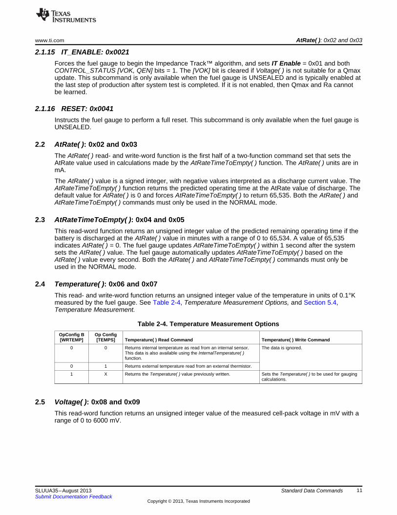
2.4 Temperature( ): 0x06 and 0x07This read- and write-word function returns an unsigned integer value of the temperature in units of 0.1°Kmeasured by the fuel gauge. See Table 2-4, Temperature Measurement Options, and Section 5.4,Temperature Measurement.
Table 2-4. Temperature Measurement OptionsOpConfig B Op Config[WRTEMP] [TEMPS] Temperature( ) Read Command Temperature( ) Write Command
0 0 Returns internal temperature as read from an internal sensor. The data is ignored.This data is also available using the InternalTemperature( )function.
0 1 Returns external temperature read from an external thermistor.
1 X Returns the Temperature( ) value previously written. Sets the Temperature( ) to be used for gaugingcalculations.
2.5 Voltage( ): 0x08 and 0x09This read-word function returns an unsigned integer value of the measured cell-pack voltage in mV with arange of 0 to 6000 mV.
11SLUUA35–August 2013 Standard Data CommandsSubmit Documentation Feedback
Copyright © 2013, Texas Instruments Incorporated

Flags( ): 0x0A and 0x0B www.ti.com
2.6 Flags( ): 0x0A and 0x0BThis read-word function returns the contents of the fuel-gauge status register, depicting the currentoperating status.
Table 2-5. Flags Bit Definitionsbit7 bit6 bit5 bit4 bit3 bit2 bit1 bit0
High Byte OTC OTD – CALMODE CHG_INH XCHG FC CHGLow Byte – – OCV_GD WAIT_ID BAT_DET SOC1 SYSDOWN DSG
High ByteOTC = Overtemperature in charge condition is detected. True when set. See Table 4-3, Safety Subclass
parameters for threshold settings. If the OpConfig D [SOC_OT] bit = 1, SOC_INT pin toggles once [OTC] bitis set.
OTD = Overtemperature in discharge condition is detected. True when set. If the OpConfig D [SOC_OT] bit = 1,SOC_INT pin toggles once [OTD] bit is set.
CALMODE = Status bit indicating the calibration function is active. True when set. This bit must be cleared when thedevice is in NORMAL mode.
CHG_INH = Charge inhibit: If set, indicates that charging should not begin because Temperature( ) is outside the range[Charge Inhibit Temp Low, Charge Inhibit Temp High]. True when set.
XCHG = Charge suspend alert (temperature outside the range [Suspend Temperature Low, Suspend TemperatureHigh]). True when set.
FC = Full-charged is detected. If FC Set% = –1, the [FC] bit is set when the fuel gauge has detected chargetermination.Alternatively, if FC Set% is configured with a positive % threshold, the [FC] bit is set when theStateOfCharge( ) is larger than the FC Set% threshold and cleared when the StateOfCharge( ) is lower thanthe FC Clear% threshold. (See Section 5.5, Charging and Charge Termination Indication)
CHG = Indicates OK to charge. This bit is set if StateOfCharge( ) is below TCA Set % and Temperature( ) is withinthe ranges set by Chg Inhibit Temp Low/High and Suspend Low/High Temp.This bit is cleared when StateOfCharge( ) rises above TCA Clear %, unless TCA Clear % is set to –1.If TCA Clear % = –1, then this bit is cleared when primary charge termination is detected.If FC Set % = –1, then the CHG bit clears at the same moment as the FC bit is set when primary chargetermination is detected.
Low ByteOCV_GD = Good OCV measurement taken. True when set.WAIT_ID = Waiting to identify inserted battery. True when set.
BAT_DET = Battery detected. True when set.SOC1 = State-of-charge threshold 1 (SOC1 Set) reached. SOC_INT pin toggles once when this bit is set or cleared if
OpConfig B [BL_INT] bit = 1. True when set.SYSDOWN = System down bit indicating the system should shut down. See Table 4-3, Discharge Subclass, SysDown
parameters for threshold settings. True when set. SOC_INT pin toggles once if set.DSG = Discharging detected. True when set.
2.7 NominalAvailableCapacity( ): 0x0C and 0x0DThis read-only command pair returns the uncompensated (less than C/20 load) battery capacityremaining. Units are mAh.
2.8 FullAvailableCapacity( ): 0x0E and 0x0FThis read-only command pair returns the uncompensated (less than C/20 load) capacity of the batterywhen fully charged. Units are mAh. FullAvailableCapacity( ) is updated at regular intervals, as specified bythe Impedance Track™ algorithm.
2.9 RemainingCapacity( ): 0x10 and 0x11This read-only command pair returns the compensated battery capacity remaining (UnfilteredRM( )) whenthe OpConfig D [SMTHEN] bit is cleared or filtered compensated battery capacity remaining(FilteredRM( )) when the [SMTHEN] bit is set. Units are mAh.
12 Standard Data Commands SLUUA35–August 2013Submit Documentation Feedback
Copyright © 2013, Texas Instruments Incorporated

www.ti.com FullChargeCapacity( ): 0x12 and 0x13
2.10 FullChargeCapacity( ): 0x12 and 0x13This read-only command pair returns the compensated capacity of fully charged battery (UnfilteredFCC( ))when the OpConfig D [SMTHEN] bit is cleared or filtered compensated capacity of fully charged battery(FilteredFCC( )) when the [SMTHEN] bit is set. Units are mAh. FullChargeCapacity( ) is updated at regularintervals, as specified by the Impedance Track™ algorithm.
2.11 AverageCurrent( ): 0x14 and 0x15This read-only command pair returns a signed integer value that is the average current flow through thesense resistor. In NORMAL mode, it is updated once per second and is calculated by dividing the 1-second change in coulomb counter data by 1 second. Large current spikes of short duration are averagedout in this measurement. Units are mA.
2.12 TimeToEmpty( ): 0x16 and 0x17This read-only function returns an unsigned integer value of the predicted remaining battery life at thepresent rate of discharge, in minutes. A value of 65,535 indicates battery is not being discharged.
2.13 StandbyCurrent( ): 0x18 and 0x19This read-only function returns a signed integer value of the measured standby current through the senseresistor. The StandbyCurrent( ) is an adaptive measurement. Initially it reports the standby currentprogrammed in Initial Standby, and after spending several seconds in standby, reports the measuredstandby current.
The register value is updated every second when the measured current is above the Deadband and isless than or equal to 2 × Initial Standby. The first and last values that meet this criteria are not included,because they may not be stable values. To approximate a 1-minute time constant, each newStandbyCurrent( ) value is computed by taking approximately 93% weight of the last standby current andapproximately 7% of the current measured average current.
2.14 StandbyTimeToEmpty( ): 0x1A and 0x1BThis read-only function returns an unsigned integer value of the predicted remaining battery life at thestandby rate of discharge in minutes. The computation uses NominalAvailableCapacity( ) (NAC), theuncompensated remaining capacity, for this computation. A value of 65,535 indicates battery is not beingdischarged.
2.15 StateofHealth( ): 0x1C and 0x1D0x28 SOH percentage: this read-only function returns an unsigned integer value, expressed as apercentage of the ratio of predicted FCC(25°C, SOH LoadI) over the DesignCapacity( ). The FCC(25°C,SOH LoadI) is the calculated full charge capacity at 25°C and the SOH LoadI which is specified in thedata flash. The range of the returned SOH percentage is 0x00 to 0x64, indicating 0 to 100%,correspondingly.
0x29 SOH status: this read-only function returns an unsigned integer value, indicating the status of theSOH percentage. The meanings of the returned value are:• 0x00: SOH not valid before initialization• 0x01: Instant SOH value ready• 0x02: Initial SOH value ready. The calculation is based on unlearned Qmax and is updated at the first
grid point during discharge after cell insertion.• 0x03: SOH value ready. The calculation is based on an updated learned Qmax value. The updated
Qmax value is measured after charge/relaxation or Fast Qmax conditions are met.• 0x04 to 0xFF: Reserved
13SLUUA35–August 2013 Standard Data CommandsSubmit Documentation Feedback
Copyright © 2013, Texas Instruments Incorporated

CycleCount( ): 0x1E and 0x1F www.ti.com
2.16 CycleCount( ): 0x1E and 0x1FThis read-only function returns an unsigned integer value of the number of cycles that the active cell hasexperienced with a range of 0 to 65535. One cycle occurs when accumulated discharge ≥ CC Threshold.The gauge maintains a separate cycle counter for both cell profiles and resets to 0 if the insertion of a newpack has been detected.
2.17 StateOfCharge( ): 0x20 and 0x21This read-only function returns an unsigned integer value of the predicted remaining battery capacityexpressed as a percentage of FullChargeCapacity( ), with a range of 0 to 100%. StateOfCharge( ) =RemainingCapacity( ) ÷ FullChargeCapacity( ) rounded up to the nearest whole percentage point.
2.18 InstantaneousCurrent( ): 0x22 and 0x23This read-only function returns a signed integer value that is the instantaneous current flow through thesense resistor. The conversion time is 125 ms. It is updated every second. Units are mA.
2.19 InternalTemperature( ): 0x28 and 0x29This read-only function returns an unsigned integer value of the internal temperature sensor in units of0.1°K measured by the fuel gauge. This function can be useful as an additional system-level temperaturemonitor if the main Temperature( ) function is configured for external or host-reported temperature.
2.20 ResistanceScale( ): 0x2A and 0x2BThis read-only function returns the resistance scale value when the Fast Resistance Scaling feature isenabled via the OpConfig B [FCE] bit. (See Section 5.1.14, Fast Resistance Scaling.)
2.21 OperationConfiguration( ): 0x2C and 0x2DThis read-only function returns the contents of the data flash Op Config register and is most useful forsystem level debug to quickly determine device configuration.
2.22 DesignCapacity( ): 0x2E and 0x2FThis read-only function returns the value stored in Design Capacity and is expressed in mAh. This isintended to be the theoretical or nominal capacity of a new pack, and is used for the calculation ofStateOfHealth( ).
2.23 UnfilteredRM( ): 0x6C and 0x6DThis read-only command pair returns the compensated battery capacity remaining. When the OpConfig D[SMTHEN] bit is cleared, this value is reported in the RemainingCapacity( ) register. Units are mAh.
2.24 FilteredRM( ): 0x6E and 0x6FThis read-only command pair returns the filtered compensated battery capacity remaining. When theOpConfig D [SMTHEN] bit is set, this value is reported in the RemainingCapacity( ) register. Units aremAh.
2.25 UnfilteredFCC( ): 0x70 and 0x71This read-only command pair returns the compensated capacity of the battery when fully charged. Whenthe OpConfig D [SMTHEN] bit is cleared, this value is reported in the RemainingCapacity( ) register.Units are mAh. UnFilteredFCC( ) is updated at regular intervals, as specified by the Impedance Track™algorithm.
14 Standard Data Commands SLUUA35–August 2013Submit Documentation Feedback
Copyright © 2013, Texas Instruments Incorporated

www.ti.com FilteredFCC( ): 0x72 and 0x73
2.26 FilteredFCC( ): 0x72 and 0x73This read-only command pair returns the filtered compensated capacity of the battery when fully charged.When the OpConfig D [SMTHEN] bit is set, this value is reported in the RemainingCapacity( ) register.Units are mAh. FilteredFCC( ) is updated at regular intervals, as specified by the Impedance Track™algorithm.
2.27 TrueSOC( ): 0x74 and 0x75This read-only function returns an unsigned integer value of the predicted remaining battery capacityexpressed as a percentage of UnfilteredFCC( ), with a range of 0 to 100%. When the OpConfig D[SMTHEN] bit is cleared, this value is reported in the StateOfCharge( ) register.
15SLUUA35–August 2013 Standard Data CommandsSubmit Documentation Feedback
Copyright © 2013, Texas Instruments Incorporated

Chapter 3SLUUA35–August 2013
Extended Data Commands
Extended commands offer additional functionality beyond the standard set of commands. They are used inthe same manner; however, unlike standard commands, extended commands are not limited to 2-bytewords. The number of command bytes for a given extended command range in size from single to multiplebytes is specified in Table 3-1. See Section 4.1 for details on accessing the data flash and Section 4.6 foran example to update a data flash parameter.
Table 3-1. Extended Data CommandsCommand SEALED UNSEALEDName UnitCode Access (1) (2) Access (1) (2)
Reserved 0x34 to 0x3D NA R RDataFlashClass( ) (2) 0x3E NA NA RWDataFlashBlock( ) (2) 0x3F NA RW RWBlockData( ) 0x40 to 0x5F NA R RWBlockDataCheckSum( ) 0x60 NA RW RWBlockDataControl( ) 0x61 NA NA RWApplicationStatus( ) 0x6A NA R RReserved 0x6B to 0x7F NA R R
(1) SEALED and UNSEALED states are entered via commands to Control( ) 0x00 and 0x01.(2) In sealed mode, data flash cannot be accessed through commands 0x3E and 0x3F.
3.1 DataFlashClass( ): 0x3EUNSEALED Access: This command sets the data flash class to be accessed. The class to be accessedmust be entered in hexadecimal.
SEALED Access: This command is not available in SEALED mode.
3.2 DataFlashBlock( ): 0x3FUNSEALED Access: This command sets the data flash block to be accessed. When 0x00 is written toBlockDataControl( ), DataFlashBlock( ) holds the block number of the data flash to be read or written.Example: writing a 0x00 to DataFlashBlock( ) specifies access to the first 32-byte block, a 0x01 specifiesaccess to the second 32-byte block, and so on.
SEALED Access: This command directs which data flash block is accessed by the BlockData( )command. Writing a 0x01 or 0x02 instructs the BlockData( ) command to transfer the Manufacturer InfoBlock. All other DataFlashBlock( ) values are reserved.
3.3 BlockData( ): 0x40 to 0x5FUNSEALED Access: This data block is the remainder of the 32-byte data block when accessing dataflash.
SEALED Access: This data block is the remainder of the 32-byte data block when accessingManufacturer Info Block.
16 Extended Data Commands SLUUA35–August 2013Submit Documentation Feedback
Copyright © 2013, Texas Instruments Incorporated

www.ti.com BlockDataChecksum( ): 0x60
3.4 BlockDataChecksum( ): 0x60UNSEALED Access: This byte contains the checksum on the 32 bytes of block data read from or writtento data flash. The least-significant byte of the sum of the data bytes written must be complemented([255 – x], x is the least-significant byte) before being written to 0x60.
SEALED Access: This byte contains the checksum for the 32 bytes of block data written to theManufacturer Info Block. The least-significant byte of the sum of the data bytes written must becomplemented ([255 – x], x is the least-significant byte) before being written to 0x60.
3.5 BlockDataControl( ): 0x61UNSEALED Access: This command controls the data flash access mode. Writing 0x00 to this commandenables BlockData( ) to access general data flash.
SEALED Access: This command is not available in SEALED mode.
3.6 ApplicationStatus( ): 0x6AThis byte function allows the system to read the Application Status data flash location. See Table 5-12,ApplicationStatus( ) Bit Definitions, for specific bit definitions.
17SLUUA35–August 2013 Extended Data CommandsSubmit Documentation Feedback
Copyright © 2013, Texas Instruments Incorporated

Chapter 4SLUUA35–August 2013
Data Flash Interface
4.1 Accessing The Data FlashThe bq27520-G4 data flash is a non-volatile memory that contains initialization, default, cell status,calibration, configuration, and user information. The data flash can be accessed in several different ways,depending in what mode the fuel gauge is operating and what data is being accessed.
Commonly accessed data flash memory locations, frequently read by a system, are convenientlyaccessed through specific instructions, already described in Chapter 3, Extended Data Commands. Thesecommands are available when the fuel gauge is either in UNSEALED mode or SEALED mode.
Most data flash locations, however, are only accessible in UNSEALED mode by use of the evaluationsoftware or by data flash block transfers. These locations should be optimized and/or fixed during thedevelopment and manufacture processes. They become part of a golden image file and can then bewritten to multiple systems. Once established, the values generally remain unchanged during end-equipment operation.
To access data flash locations individually, the block containing the desired data flash location(s) must betransferred to the command register locations, where they can be read to the system or changed directly.This is accomplished by sending the set-up command BlockDataControl( ) (0x61) with data 0x00. Up to 32bytes of data can be read directly from the BlockData( ) (0x40 to 0x5F), externally altered, then rewrittento the BlockData( ) command space. Alternatively, specific locations can be read, altered, and rewritten iftheir corresponding offsets are used to index into the BlockData( ) command space. Finally, once thecorrect checksum for the whole block is written to BlockDataChecksum( ) (0x60), the data residing in thecommand space is transferred to the data flash.
Occasionally, a data flash class is larger than the 32-byte block size. In this case, the DataFlashBlock( )command designates in which 32-byte block the desired locations reside. The correct command addressis then given by 0x40 + offset modulo 32. For example, to access Terminate Voltage in the Gas Gaugingclass, DataFlashClass( ) is issued 80 (0x50) to set the class. Because the offset is 55, it must reside in thesecond 32-byte block. Hence, DataFlashBlock( ) is issued 0x01 to set the block offset, and the offset usedto index into the BlockData( ) memory area is 0x40 + 55 modulo 32 = 0x40 + 23 = 0x40 + 0x17 = 0x57.
Reading and writing subclass data are block operations up to 32 bytes in length. If, during a write, the datalength exceeds the maximum block size, then the data is ignored.
None of the data written to memory are bounded by the bq27520-G4 fuel gauge – the values are notrejected by the fuel gauge. Writing an incorrect value may result in hardware failure due to firmwareprogram interpretation of the invalid data. The written data is persistent, so a power-on reset does notresolve the fault.
18 Data Flash Interface SLUUA35–August 2013Submit Documentation Feedback
Copyright © 2013, Texas Instruments Incorporated

www.ti.com Manufacturer Information Block
4.2 Manufacturer Information BlockThe fuel gauge contains 32 bytes of user programmable data flash storage called the Manufacturer InfoBlock. The method for accessing these memory locations is slightly different, depending on whether thedevice is in UNSEALED or SEALED mode.
When in UNSEALED mode and 0x00 has been written to BlockDataControl( ), accessing the manufacturerinformation blocks is identical to accessing general data flash locations. First, a DataFlashClass( )command sets the subclass, then a DataFlashBlock( ) command sets the offset for the first data flashaddress within the subclass. The BlockData( ) command codes contain the referenced data flash data.When writing to the data flash, a checksum is expected to be received by BlockDataChecksum( ). Onlywhen the checksum is received and verified is the data actually written to data flash.
When in SEALED mode or when 0x01 BlockDataControl( ) does not contain 0x00, the data flash is nolonger available in the manner used in UNSEALED mode. Rather than issuing subclass information, adesignated Manufacturer Info Block is selected with the DataFlashBlock( ) command. Issuing a 0x01 or0x02 with this command causes the corresponding information block to be transferred to the commandspace 0x40 to 0x5F for editing or reading by the system. Upon successful writing of checksum informationto BlockDataChecksum( ), the modified block is returned to the data flash.
NOTE: The Manufacturer Info Block is read-only when in SEALED mode.
4.3 Device Access ModesThe fuel gauge provides three security modes (FULL ACCESS, UNSEALED, and SEALED) that controldata flash access permissions, according to Table 4-1.
Table 4-1. Data Flash AccessSecurity Mode Data Flash Manufacturer Info BlockFULL ACCESS RW RW
UNSEALED RW RWSEALED None R
Although FULL ACCESS and UNSEALED modes appear identical, only FULL ACCESS allows the fuelgauge to read or write access-mode transition keys.
4.4 Sealing and Unsealing Data FlashThe fuel gauge implements a key-access scheme to transition between SEALED, UNSEALED, and FULLACCESS modes. Each transition requires that a unique set of two keys be sent to the fuel gauge via theControl( ) control command. The keys must be sent consecutively, with no other data being written to theControl( ) register in between. Do not set the two keys to identical values.
NOTE: To avoid conflict, the keys must be different from the codes presented in the CNTL DATAcolumn of Table 2-2, Control( ) Subcommands.
When in the SEALED mode, the CONTROL_STATUS [SS] bit is set, but when the UNSEAL keys arecorrectly received by the fuel gauge, the [SS] bit is cleared. When the FULL ACCESS keys are correctlyreceived, then the CONTROL_STATUS [FAS] bit is cleared.
Both sets of keys for each level are 2 bytes each in length and are stored in data flash. The UNSEAL key(stored at Unseal Key 0 and Unseal Key 1) and the FULL ACCESS keys (stored at Full-Access Key 0and Full-Access Key 1) can only be updated when in FULL ACCESS mode. The order of the keys is Key1 followed by Key 0. The order of the bytes entered through the Control( ) command is the reverse ofwhat is read from the part. For example, if the Key 1 and Key 0 of the UNSEAL keys returns 0x1234 and0x5678, then the Control( ) should supply 0x3412 and 0x7856 to unseal the part.
19SLUUA35–August 2013 Data Flash InterfaceSubmit Documentation Feedback
Copyright © 2013, Texas Instruments Incorporated

Data Flash Summary www.ti.com
4.5 Data Flash SummaryTable 4-3 through Table 4-10 summarize the data flash locations available to the user, including theirdefault, minimum, and maximum values.
Table 4-2. Data Type Decoder
Type Min Value Max ValueF4 ±9.8603 × 10–39 ±5.707267 × 1037
H1 0x00 0xFFH2 0x00 0xFFFFH4 0x00 0xFFFF FFFFI1 –128 127I2 –32768 32767I4 −2,147,483,648 2,147,483,647Sx 1-byte string X-byte stringU1 0 255U2 0 65535U4 0 4,294,967,295
Table 4-3. Data Flash Summary—Configuration ClassSubclass Subclass Offset Name Data Value Unit
ID Type Min Max Default2 Safety 0 OT Chg I2 0 1200 550 0.1°C
2 OT Chg Time U1 0 60 2 s3 OT Chg Recovery I2 0 1200 500 0.1°C5 OT Dsg I2 0 1200 600 0.1°C7 OT Dsg Time U1 0 60 2 s8 OT Dsg Recovery I2 0 1200 550 0.1°C
32 Charge 0 Chg Inhibit Temp Low I2 –400 1200 0 0.1°CInhibit Cfg 2 Chg Inhibit Temp High I2 –400 1200 450 0.1°C
4 Temp Hys I2 0 100 50 0.1°C
34 Charge 2 Charging Voltage I2 0 4600 4200 mV4 Delta Temp I2 0 500 50 0.1°C6 Suspend Low Temp I2 –400 1200 –50 0.1°C8 Suspend High Temp I2 –400 1200 550 0.1°C
36 Charge 2 Taper Current I2 0 1000 100 mATermination 6 Taper Voltage I2 0 1000 100 mV
9 TCA Set % I1 –1 100 99 %10 TCA Clear % I1 –1 100 95 %11 FC Set % I1 –1 100 –1 %12 FC Clear % I1 –1 100 98 %13 DODatEOC Delta T I2 0 1000 50 0.1°C
20 Data Flash Interface SLUUA35–August 2013Submit Documentation Feedback
Copyright © 2013, Texas Instruments Incorporated

www.ti.com Data Flash Summary
Table 4-3. Data Flash Summary—Configuration Class (continued)Subclass Subclass Offset Name Data Value Unit
ID Type Min Max Default48 Data 4 Initial Standby I1 –256 0 –10 mA
7 CC Threshold I2 100 32767 900 mAh10 Design Capacity I2 0 65535 1000 mAh12 Des Energy Scale U1 0 65535 1 num13 SOH LoadI I2 –32767 0 –400 mA15 Default Temperature I2 2732 3732 2982 0.1°C17 Device Name S8 x x bq2752025 Data Flash Version H2 0x0 0xFFFF 0x0 num
49 Discharge 0 SOC1 Set Threshold U2 0 5000 150 mAh2 SOC1 Clear Threshold U2 0 5000 175 mAh9 SysDown Set Volt Threshold I2 0 4200 3150 mV
11 SysDown Set Volt Time U1 0 60 2 s12 SysDown Clear Volt I2 0 4200 3400 mV14 Final Voltage U2 0 4200 3100 mV16 Final Volt Time U1 0 60 2 s21 Def Avg I Last Run I2 –32768 32767 –299 mA23 Def Avg P Last Run I2 –32768 32767 –1131 mW
64 Registers 0 Op Config H2 0x0000 0xFFFF 0x0973 flags7 SOC Delta U1 0 25 1 %8 i2c Timeout U1 0 7 4 %9 DF Wr Ind Wait U2 0 65535 0 %
11 OpConfig B H1 0x00 0xFF 0x4A flags12 OpConfig C H1 0x00 0xFF 0x2C flags13 OpConfig D H1 0x00 0xFF 0x5E flags14 OpConfig E H1 0x00 0xFF 0x00 flags
68 Power 0 Flash Update OK Voltage I2 0 4200 2800 mV4 Sleep Current I2 0 100 10 mA
13 Hibernate I U2 0 700 8 mA15 Hibernate V U2 2400 3000 2550 mV
Table 4-4. Data Flash Summary—System Data ClassSubclass Subclass Offset Name Data Value Unit
ID Type Min Max Default57 Manufacturer 0 Block 0 through 31 H1 0x00 0xFF 0x00
Info through31
21SLUUA35–August 2013 Data Flash InterfaceSubmit Documentation Feedback
Copyright © 2013, Texas Instruments Incorporated
Data Flash Summary www.ti.com
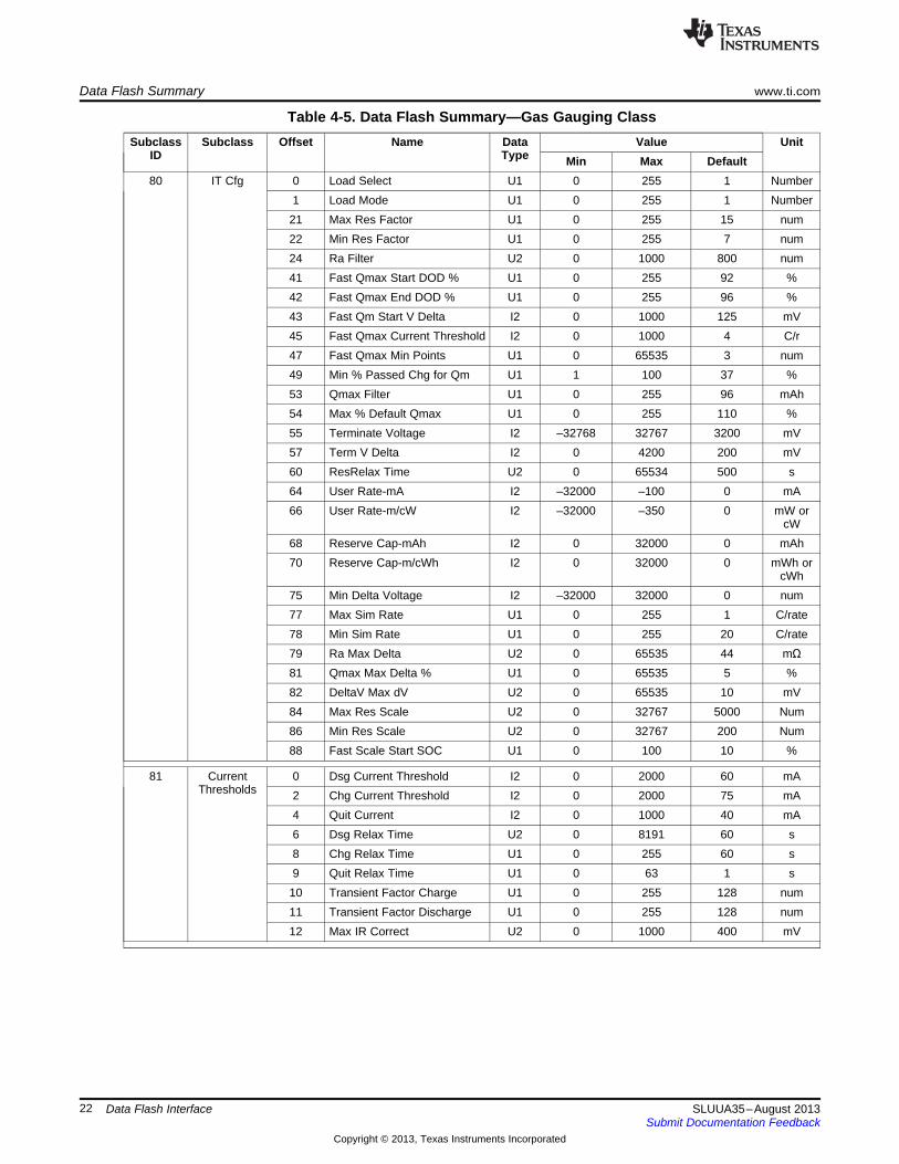
Table 4-5. Data Flash Summary—Gas Gauging ClassSubclass Subclass Offset Name Data Value Unit
ID Type Min Max Default80 IT Cfg 0 Load Select U1 0 255 1 Number
1 Load Mode U1 0 255 1 Number21 Max Res Factor U1 0 255 15 num22 Min Res Factor U1 0 255 7 num24 Ra Filter U2 0 1000 800 num41 Fast Qmax Start DOD % U1 0 255 92 %42 Fast Qmax End DOD % U1 0 255 96 %43 Fast Qm Start V Delta I2 0 1000 125 mV45 Fast Qmax Current Threshold I2 0 1000 4 C/r47 Fast Qmax Min Points U1 0 65535 3 num49 Min % Passed Chg for Qm U1 1 100 37 %53 Qmax Filter U1 0 255 96 mAh54 Max % Default Qmax U1 0 255 110 %55 Terminate Voltage I2 –32768 32767 3200 mV57 Term V Delta I2 0 4200 200 mV60 ResRelax Time U2 0 65534 500 s64 User Rate-mA I2 –32000 –100 0 mA66 User Rate-m/cW I2 –32000 –350 0 mW or
cW68 Reserve Cap-mAh I2 0 32000 0 mAh70 Reserve Cap-m/cWh I2 0 32000 0 mWh or
cWh75 Min Delta Voltage I2 –32000 32000 0 num77 Max Sim Rate U1 0 255 1 C/rate78 Min Sim Rate U1 0 255 20 C/rate79 Ra Max Delta U2 0 65535 44 mΩ81 Qmax Max Delta % U1 0 65535 5 %82 DeltaV Max dV U2 0 65535 10 mV84 Max Res Scale U2 0 32767 5000 Num86 Min Res Scale U2 0 32767 200 Num88 Fast Scale Start SOC U1 0 100 10 %
81 Current 0 Dsg Current Threshold I2 0 2000 60 mAThresholds 2 Chg Current Threshold I2 0 2000 75 mA
4 Quit Current I2 0 1000 40 mA6 Dsg Relax Time U2 0 8191 60 s8 Chg Relax Time U1 0 255 60 s9 Quit Relax Time U1 0 63 1 s
10 Transient Factor Charge U1 0 255 128 num11 Transient Factor Discharge U1 0 255 128 num12 Max IR Correct U2 0 1000 400 mV
22 Data Flash Interface SLUUA35–August 2013Submit Documentation Feedback
Copyright © 2013, Texas Instruments Incorporated

www.ti.com Data Flash Summary
Table 4-5. Data Flash Summary—Gas Gauging Class (continued)Subclass Subclass Offset Name Data Value Unit
ID Type Min Max Default82 State 0 IT Enable H1 0x0 0x3 0x0 num
1 App Status H1 0x0 0xFFFF 0x0 flags2 Qmax Cell 0 I2 0 32767 1000 mAh4 Cycle Count 0 U2 0 65535 0 Count6 Update Status 0 H1 0x0 0x3 0x0 num7 Qmax Cell 1 I2 0 32767 1000 mAh9 Cycle Count 1 U2 0 65535 0 Count
11 Update Status 1 H1 0x0 0x3 0x0 num12 Avg I Last Run I2 –32768 32767 –299 mA14 Avg P Last Run I2 –32768 32767 –1131 cW or
mW16 Delta Voltage I2 –32768 32767 2 mV20 T Rise U2 0 65535 20 Num22 T Time Constant U2 0 65535 1000 Num24 Cell 0 V at Chg Term I2 3800 4500 4200 mV26 Cell 1 V at Chg Term I2 3800 4500 4200 mV
Table 4-6. Data Flash Summary—OCV Table ClassSubclass Subclass Offset Name Data Value Unit
ID Type Min Max Default83 OCVa0 0 Chem ID H2 0x0 0xFFFF 0x100 flags
Table 2 Qmax Cell 0 I2 0 32767 1000 mAh4 Update Status H1 0x0 0x3 0x0 num
84 OCVa1 0 Chem ID H2 0x0 0xFFFF 0x100 flagsTable 2 Qmax Cell 1 I2 0 32767 1000 mAh
4 Update Status H1 0x0 0x3 0x0 num
23SLUUA35–August 2013 Data Flash InterfaceSubmit Documentation Feedback
Copyright © 2013, Texas Instruments Incorporated

Data Flash Summary www.ti.com
Table 4-7. Data Flash Summary—Default Ra Tables ClassSubclass Subclass Offset Name Data Value Unit
ID Type Min Max Default87 Def0 Ra 0 Def0 Ra status H1 0x0 0x0 0xFF
1 Def0 Ra flag H1 0x0 0x0 0x552 Def0 Ra Base R I2 –200 200 414 Def0 Ra Gain H1 0x0 0x0 0x05 Def0 Ra 1 I1 –128 127 2 2–10 Ω6 Def0 Ra 2 I1 –128 127 –4 2–10 Ω7 Def0 Ra 3 I1 –128 127 0 2–10 Ω8 Def0 Ra 4 I1 –128 127 –2 2–10 Ω9 Def0 Ra 5 I1 –128 127 2 2–10 Ω
10 Def0 Ra 6 I1 –128 127 6 2–10 Ω11 Def0 Ra 7 I1 –128 127 7 2–10 Ω12 Def0 Ra 8 I1 –128 127 5 2–10 Ω13 Def0 Ra 9 I1 –128 127 8 2–10 Ω14 Def0 Ra 10 I1 –128 127 15 2–10 Ω15 Def0 Ra 11 I1 –128 127 30 2–10 Ω16 Def0 Ra 12 I1 –128 127 54 2–10 Ω17 Def0 Ra 13 I1 –128 127 87 2–10 Ω18 Def0 Ra 14 I1 –128 127 115 2–10 Ω
88 Def1 Ra 0 Def1 Ra status H1 0x0 0x0 0xFF1 Def1 Ra flag H1 0x0 0x0 0x552 Def1 Ra Base R I2 –200 200 414 Def1 Ra Gain H1 0x0 0x0 0x05 Def1 Ra 1 I1 –128 127 2 2–10 Ω6 Def1 Ra 2 I1 –128 127 –4 2–10 Ω7 Def1 Ra 3 I1 –128 127 0 2–10 Ω8 Def1 Ra 4 I1 –128 127 –2 2–10 Ω9 Def1 Ra 5 I1 –128 127 2 2–10 Ω
10 Def1 Ra 6 I1 –128 127 6 2–10 Ω11 Def1 Ra 7 I1 –128 127 7 2–10 Ω12 Def1 Ra 8 I1 –128 127 5 2–10 Ω13 Def1 Ra 9 I1 –128 127 8 2–10 Ω14 Def1 Ra 10 I1 –128 127 15 2–10 Ω15 Def1 Ra 11 I1 –128 127 30 2–10 Ω16 Def1 Ra 12 I1 –128 127 54 2–10 Ω17 Def1 Ra 13 I1 –128 127 87 2–10 Ω18 Def1 Ra 14 I1 –128 127 115 2–10 Ω
24 Data Flash Interface SLUUA35–August 2013Submit Documentation Feedback
Copyright © 2013, Texas Instruments Incorporated

www.ti.com Data Flash Summary
Table 4-8. Data Flash Summary—Ra Tables ClassSubclass Subclass Offset Name Data Value Unit
ID Type Min Max Default91 Pack0 Ra 0 Pack0 Ra status H1 0x0 0x0 0xFF
1 Pack0 Ra flag H1 0x0 0x0 0x552 Pack0 Ra Base R I2 –200 200 414 Pack0 Ra Gain H1 0x0 0x0 0x05 Pack0 Ra 1 I1 –128 127 2 2–10 Ω6 Pack0 Ra 2 I1 –128 127 –4 2–10 Ω7 Pack0 Ra 3 I1 –128 127 0 2–10 Ω8 Pack0 Ra 4 I1 –128 127 –2 2–10 Ω9 Pack0 Ra 5 I1 –128 127 2 2–10 Ω
10 Pack0 Ra 6 I1 –128 127 6 2–10 Ω11 Pack0 Ra 7 I1 –128 127 7 2–10 Ω12 Pack0 Ra 8 I1 –128 127 5 2–10 Ω13 Pack0 Ra 9 I1 –128 127 8 2–10 Ω14 Pack0 Ra 10 I1 –128 127 15 2–10 Ω15 Pack0 Ra 11 I1 –128 127 30 2–10 Ω16 Pack0 Ra 12 I1 –128 127 54 2–10 Ω17 Pack0 Ra 13 I1 –128 127 87 2–10 Ω18 Pack0 Ra 14 I1 –128 127 115 2–10 Ω
92 Pack1 Ra 0 Pack1 Ra status H1 0x0 0x0 0xFF1 Pack1 Ra flag H1 0x0 0x0 0x552 Pack1 Ra Base R I2 –200 200 414 Pack1 Ra Gain H1 0x0 0x0 0x05 Pack1 Ra 1 I1 –128 127 2 2–10 Ω6 Pack1 Ra 2 I1 –128 127 –4 2–10 Ω7 Pack1 Ra 3 I1 –128 127 0 2–10 Ω8 Pack1 Ra 4 I1 –128 127 –2 2–10 Ω9 Pack1 Ra 5 I1 –128 127 2 2–10 Ω
10 Pack1 Ra 6 I1 –128 127 6 2–10 Ω11 Pack1 Ra 7 I1 –128 127 7 2–10 Ω12 Pack1 Ra 8 I1 –128 127 5 2–10 Ω13 Pack1 Ra 9 I1 –128 127 8 2–10 Ω14 Pack1 Ra 10 I1 –128 127 15 2–10 Ω15 Pack1 Ra 11 I1 –128 127 30 2–10 Ω16 Pack1 Ra 12 I1 –128 127 54 2–10 Ω17 Pack1 Ra 13 I1 –128 127 87 2–10 Ω18 Pack1 Ra 14 I1 –128 127 115 2–10 Ω
25SLUUA35–August 2013 Data Flash InterfaceSubmit Documentation Feedback
Copyright © 2013, Texas Instruments Incorporated

Data Flash Summary www.ti.com
Table 4-8. Data Flash Summary—Ra Tables Class (continued)Subclass Subclass Offset Name Data Value Unit
ID Type Min Max Default93 Pack0 Rax 0 Pack0 Rax status H1 0x0 0x0 0xFF
1 Pack0 Rax flag H1 0x0 0x0 0xFF2 Pack0 Rax Base R I2 –200 200 414 Pack0 Rax Gain H1 0x0 0x0 0x05 Pack0 Rax 1 I1 –128 127 2 2–10 Ω6 Pack0 Rax 2 I1 –128 127 –4 2–10 Ω7 Pack0 Rax 3 I1 –128 127 0 2–10 Ω8 Pack0 Rax 4 I1 –128 127 –2 2–10 Ω9 Pack0 Rax 5 I1 –128 127 2 2–10 Ω
10 Pack0 Rax 6 I1 –128 127 6 2–10 Ω11 Pack0 Rax 7 I1 –128 127 7 2–10 Ω12 Pack0 Rax 8 I1 –128 127 5 2–10 Ω13 Pack0 Rax 9 I1 –128 127 8 2–10 Ω14 Pack0 Rax 10 I1 –128 127 15 2–10 Ω15 Pack0 Rax11 I1 –128 127 30 2–10 Ω16 Pack0 Rax 12 I1 –128 127 54 2–10 Ω17 Pack0 Rax 13 I1 –128 127 87 2–10 Ω18 Pack0 Rax 14 I1 –128 127 115 2–10 Ω
94 Pack1 Rax 0 Pack1 Rax status H1 0x0 0x0 0xFF1 Pack1 Rax flag H1 0x0 0x0 0xFF2 Pack1 Rax Base R I2 –200 200 414 Pack1 Rax Gain H1 0x0 0x0 0x05 Pack1 Rax 1 I1 –128 127 2 2–10 Ω6 Pack1 Rax 2 I1 –128 127 –4 2–10 Ω7 Pack1 Rax 3 I1 –128 127 0 2–10 Ω8 Pack1 Rax 4 I1 –128 127 –2 2–10 Ω9 Pack1 Rax 5 I1 –128 127 2 2–10 Ω
10 Pack1 Rax 6 I1 –128 127 6 2–10 Ω11 Pack1 Rax 7 I1 –128 127 7 2–10 Ω12 Pack1 Rax 8 I1 –128 127 5 2–10 Ω13 Pack1 Rax 9 I1 –128 127 8 2–10 Ω14 Pack1 Rax 10 I1 –128 127 15 2–10 Ω15 Pack1 Rax 11 I1 –128 127 30 2–10 Ω16 Pack1 Rax 12 I1 –128 127 54 2–10 Ω17 Pack1 Rax 13 I1 –128 127 87 2–10 Ω18 Pack1 Rax 14 I1 –128 127 115 2–10 Ω
26 Data Flash Interface SLUUA35–August 2013Submit Documentation Feedback
Copyright © 2013, Texas Instruments Incorporated

www.ti.com Data Flash Parameter Update Example
Table 4-9. Data Flash Summary—Calibration ClassSubclass Subclass Offset Name Data Value Unit
ID Type Min Max Default104 Data 0 CC Gain F4 (1) 0.119 47.68 10.0 (2) Number
4 CC Delta F4 (1) 4.76 190 10.0 (2) Number8 CC Offset I2 –157 157 5.76 (2) mA
12 Board Offset I1 –0.96 0.96 0 µA13 Int Temp Offset I1 –128 127 0 Number14 Ext Temp Offset I1 –128 127 0 Number15 Pack V Offset I1 –128 127 0 Number
106 Temp Model 0 Ext a Coef 1 I2 –32768 32767 –11130 num2 Ext a Coef 2 I2 –32768 32767 19142 num4 Ext a Coef 3 I2 –32768 32767 –19262 num6 Ext a Coef 4 I2 –32768 32767 28203 num8 Ext a Coef 5 I2 –32768 32767 892 num
10 Ext b Coef 1 I2 –32768 32767 328 num12 Ext b Coef 2 I2 –32768 32767 –605 num14 Ext b Coef 3 I2 –32768 32767 –2443 num16 Ext b Coef 4 I2 –32768 32767 4696 num
107 Current 1 Deadband U1 0 255 5 mA(1) Not IEEE floating point.(2) Displayed as the value EVSW displayed. Data Flash value is different. For CC calibration values, please follow the Host System
Calibration Method Application Report (SLUA640).
Table 4-10. Data Flash Summary—Security ClassSubclass Subclass Offset Name Data Value Unit
ID Type Min Max Default112 Codes 0 Sealed to Unsealed H4 0x0 0xFFFF FFFF 0x0
4 Unsealed to Full H4 0x0 0xFFFF FFFF 0x0
Table 4-11. Data Flash to EVSW or GaugeStudio ConversionData FlashSubclass Data Data Flash Data Flash EVSW EVSWClass Subclass Offset Name to EVSWID Type Default Unit Default Unit Conversion
Configuration 48 Data Default15 I2 2982 °K 250 0.1°C DF – 2732Temperature
64 Registers 9 DF Wr Ind Wait U2 0 0.2 µs 0 µs DF × 5
Calibration 104 Data 0 CC Gain F4 0.4768 number 10 mΩ 4.768 ÷ DF
4 CC Delta F4 567744.6 number 10 mΩ 5677445 ÷ DF
8 CC Offset I2 –1200 number –5.76 mV DF × 0.0048
12 Board Offset I1 0 number 0 µV DF × 0.0075
4.6 Data Flash Parameter Update ExampleThis section shows an example of the command sequence that modifies a data flash parameter whiledevice firmware is still running. It can update one or more parameters without going to ROM mode andloading a new data flash image (.dfi, .dmi, or .dffs file).
For this example, the OpConfig B [WRTEMP] bit of the fuel gauge is changed from 0 to 1.
Some bq27520-G4 pins are configured via the OpConfig B register. This register is programmed andread via the methods described in Section 4.1, Accessing The Data Flash. See Section 4.5, Data FlashSummary, for the location (subclass and offset) of these configuration registers.
27SLUUA35–August 2013 Data Flash InterfaceSubmit Documentation Feedback
Copyright © 2013, Texas Instruments Incorporated

Data Flash Parameter Update Example www.ti.com
Table 4-12. OpConfig B Register Bit Definitionsbit7 bit6 bit5 bit4 bit3 bit2 bit1 bit0
Byte WRTEMP BIE BL_INT GNDSEL FCE DFWrIndBL RFACTSTEP RSVDDefault 0 1 0 0 1 0 1 0
0x4A
WRTEMP = Enables the temperature write. The temperature is expected to be written by the host and is used forgauging. Neither the external thermistor or internal temperature sensor is used. True when set.
Note that subclass ID and offset values in Table 4-13 are in decimal format. The example below hasconverted these to hexadecimal. For example, the OpConfig B subclass is d64 = 0x40.
Table 4-13. Data Flash Summary—ConfigurationSubclass Data Default
ID Subclass Offset Name Type Min Value Max Value Value Unit64 Registers 11 OpConfig B H1 0x00 0xFF 0x4A hex
4.6.1 Modify WRTEMP of OpConfig B Register
1. Unseal the device by using the Control( ) (0x00 and 0x01) command if the device is SEALED.(a) Write the first 2 bytes of the UNSEAL key using the Control(0x0414) command.
(wr 0x00 0x14 0x04)(b) Write the second 2 bytes of the UNSEAL key using the Control(0x3672) command.
(wr 0x00 0x72 0x36)2. Write 0x00 using BlockDataControl( ) command (0x61) to enable block data flash control.
(wr 0x61 0x00)3. Write 0x40 (OpConfig B Subclass) using the DataFlashClass( ) command (0x3E) to access the
registers subclass.(wr 0x3E 0x40)
4. Write the block offset location using DataFlashClass( ) command (0x3F). To access data located atoffset 0 to 31 use offset = 0x00. To access data located at offset 32 to 41 use offset = 0x01.For example, OpConfig B (offset = 11) is in the first block so use:(wr 0x3F 0x00)
5. To read the data of a specific offset use address 0x40 + mod(offset, 32).For example OpConfig B (offset = 11) is located at 0x4B, read 1 byte starting at 0x4B address.(rd 0x4B old_OP_CONF_B_BYTE)In our example, assume WRTEMP(MSB) is cleared.
6. To read the 1-byte checksum use the BlockDataChecksum( ) command (0x60).(rd 0x60 OLD_checksum)
7. In this example, set WRTEMP by setting the most-significant bit of OP_CONF_B_BYTE.8. The new value for OP_CONF_B_BYTE can be written by writing to the specific offset location.
For example to write 1-byte OP_CONF_B_BYTE new value with MSB set to OpConfig B (offset = 11)located at 0x4B, use command: (wr 0x4B new_OP_CONF_B_BYTE)
9. The data is actually transferred to the data flash when the correct checksum for the whole block (0x40to 0x5F) is written to BlockDataChecksum( ) (0x60).(wr 0x60 NEW_checksum)The checksum is (255 – x) where x is the 8-bit summation of the BlockData( ) (0x40 to 0x5F) on abyte-by-byte basis. A quick way to calculate the new checksum is to make use of the old checksum:(a) temp = mod(255 – OLD_checksum – old_OP_CONF_B_BYTE, 256)(b) NEW_checksum = 255 – mod(temp + new_OP_CONF_B_BYTE, 256)
28 Data Flash Interface SLUUA35–August 2013Submit Documentation Feedback
Copyright © 2013, Texas Instruments Incorporated
www.ti.com Data Flash Parameter Update Example
10. RESET the gauge to ensure the new data flash parameter goes into effect by using Control(0x0041).(wr 0x00 0x41 0x00)If previously sealed, then the gauge automatically becomes sealed again after RESET.
11. If not previously sealed, then SEAL the gauge by using Control(0x0020).(wr 0x00 0x20 0x00)
29SLUUA35–August 2013 Data Flash InterfaceSubmit Documentation Feedback
Copyright © 2013, Texas Instruments Incorporated

Chapter 5SLUUA35–August 2013
Functional Description
5.1 Impedance Track™ VariablesThe bq27520-G4 fuel gauge has a number of data flash variables that permit the user to customize theImpedance Track™ algorithm for optimal performance. These variables are dependent upon the powercharacteristics of the application as well as the cell itself.
5.1.1 Load ModeLoad Mode selects either the constant-current or constant-power model for the Impedance Track™algorithm as used in Load Select (see Section 5.1.2). When Load Mode is 0, the constant-current modelis used (default). When Load Mode is 1, the constant-power model is used. The CONTROL_STATUS[LDMD] bit shows the status of Load Mode.
5.1.2 Load SelectLoad Select defines the type of power or current model that computes the load-compensated capacity inthe Impedance Track™ algorithm.
If Load Mode = 0 (constant-current model), then the options presented in Table 5-1 are available.
Table 5-1. Constant-Current Model Used When Load Mode = 0Load Select Value Current Model Used
0 The average discharge current from previous cycle, Avg I Last Run. (See Section 5.1.10)Present average discharge current: This is the average discharge current from the beginning of this discharge1 (default) cycle until present time.
2 Average current: based on AverageCurrent( )3 Current: based off of a low-pass-filtered version of AverageCurrent( ) (τ = 14 s)4 Design capacity / 5: C Rate based off of Design Capacity /5 or a C/5 rate in mA.5 AtRate (mA): Use whatever current is in AtRate( )6 User_Rate-mA: Use the value in User_Rate-mA. This mode provides a completely user-configurable method.
If Load Mode = 1 (constant-power model), then the options shown in Table 5-2 are available.
Table 5-2. Constant-Power Model Used When Load Mode = 1Load Select Value Power Model Used
0 The average discharge power from previous cycle, Avg P Last Run. (See Section 5.1.11)Present average discharge power: This is the average discharge power from the beginning of this discharge1 (default) cycle until present time.
2 Average current × voltage: based off the AverageCurrent( ) and Voltage( )3 Current × voltage: based off of a low-pass-filtered version of AverageCurrent( ) (τ = 14 s) and Voltage( )4 Design energy / 5: C Rate based off of Design Energy /5 or a C/5 rate in mA.5 AtRate (10 mW): Use the value is in AtRate( ).
User_Rate–10mW: Use the value in User_Rate–10mW. This mode provides a completely user-configurable6 method.
30 Functional Description SLUUA35–August 2013Submit Documentation Feedback
Copyright © 2013, Texas Instruments Incorporated

www.ti.com Impedance Track™ Variables
5.1.3 Reserve Cap-mAh, Reserve Cap-mWh/cWhReserve Cap-mAh (Load Mode = 0) or Reserve Cap-mWh/cWh (Load Mode = 1) determines howmuch actual remaining capacity exists when the fuel gauge reports zero for RemainingCapacity( ) beforereaching the Terminate Voltage. This accommodates a controlled shutdown scheme based on batterycapacity rather than a specific voltage. A loaded rate or no-load rate of compensation can be selected forReserve Cap-mAh via the Op Config [RESCAP] bit.
5.1.4 Design Energy ScaleDesign energy scaling accommodates large capacity battery packs greater than approximately 6000 mAh.Des Energy Scale selects the scale and unit of a set of data flash parameters. The value of Des EnergyScale can be either 1 or 10, only. For batteries less than 6000 mAh, a setting of 1 is recommended. Forbatteries greater than 6000 mAh, a setting of 10 is recommended.
Table 5-3. Data Flash Parameter Scale and Unit Based on Design Energy ScaleData Flash Design Energy Scale = 1 (default) Design Energy Scale = 10
Design Energy mWh cWh
Reserve Capacity–mWh/cWh mWh cWh
Avg Power Last Run mW cW
User Rate–mW/cW mWh cWh
T Rise No Scale (example: default is 20) Scaled by x10 (example: default is 200)
5.1.5 Dsg Current ThresholdThis register is used as a threshold by many functions in the fuel gauge to determine if significantdischarge current is flowing into or out of the cell. The default for this register is in Table 4-5, CurrentThresholds Subclass, which should be sufficient for most applications. This threshold should be set lowenough to be below any normal application load current but high enough to prevent noise or drift fromaffecting the measurement.
5.1.6 Chg Current ThresholdThis register is used as a threshold by many functions in the fuel gauge to determine if significant chargecurrent is flowing into or out of the cell. The default for this register is in Table 4-5, Current ThresholdsSubclass, which should be sufficient for most applications. This threshold should be set low enough to bebelow any normal charge current but high enough to prevent noise or drift from affecting themeasurement.
5.1.7 Quit Current, Dsg Relax Time, Chg Relax Time, and Quit Relax TimeThe Quit Current is used as part of the Impedance Track™ algorithm to determine when the fuel gaugeenters the relaxation mode from a current-flowing mode in either the charge direction or the dischargedirection. The value of Quit Current is set to a default value in Table 4-5, Current Thresholds Subclass,and should be above the standby current of the system.
Either of the following criteria must be met to enter the relaxation mode:• | AverageCurrent( ) | < | Quit Current | for Dsg Relax Time• | AverageCurrent( ) | < | Quit Current | for Chg Relax TimeAfter about 5 minutes in relaxation mode, the fuel gauge attempts to take accurate OCV readings. Anadditional requirement of dV/dt < 1 μV/s is required for the fuel gauge to perform Qmax updates. Theseupdates are used in the Impedance Track™ algorithms. It is critical that the battery voltage be relaxedduring OCV readings and that the current is not higher than C/20 when attempting to go into relaxationmode.
Quit Relax Time specifies the minimum time required for AverageCurrent( ) to remain above the DsgCurrent Threshold or Chg Current Threshold before exiting the relaxation mode. See ApplicationReport SLUA450, Theory and Implementation of Impedance Track Battery Fuel-Gauging Algorithm, formore information.
31SLUUA35–August 2013 Functional DescriptionSubmit Documentation Feedback
Copyright © 2013, Texas Instruments Incorporated

Impedance Track™ Variables www.ti.com
5.1.8 Qmax Cell 0 and Qmax Cell 1Generically called Qmax, these dynamic variables contain the respective maximum chemical capacity ofthe active cell profiles, and are determined by comparing states of charge before and after applying theload with the amount of charge passed. They also correspond to capacity at a low rate of discharge, suchas the C/20 rate. For high accuracy, this value is periodically updated by the fuel gauge during operation.Based on the battery cell capacity information, the initial value of chemical capacity should be entered inthe Qmax n field for each default cell profile. The Impedance Track™ algorithm updates these values andmaintains them in the associated cell profiles.
Qmax Max Delta % is the percent of DesignCapacity( ) to limit how much Qmax may grow or shrinkduring any one Qmax update. The default is 5%.
Min % Passed Chg for Qm represents the approximate change in SOC that is required as part of thequalification for Qmax updates. It is not recommended to change this value.
Qmax Filter. Qmax updates are filtered to prevent corrupt values. It is not recommended to change thisvalue.
Although there is variation between batteries, in general Qmax should only decrease over time and use.Max % Default Qmax prevents erroneous updates from being recorded if they are too high.
5.1.9 Update Status 0 and Update Status 1The Update Status n registers are modified automatically by the fuel gauge and the TI evaluationsoftware during the process of creating a golden Data Flash file. A golden file with optimized Qmax andresistance values should have the Update Status = 2.
5.1.10 Avg I Last RunThe fuel gauge computes average current from the beginning to the end of each discharge cycle andstores the average current from the previous discharge period in this register if the duration is > 500seconds. This register should not be modified by the host as it is automatically updated by the fuel gaugewhen required. For a golden file, this register should be initially set to a typical system discharge currentlevel.
5.1.11 Avg P Last RunThe fuel gauge computes average power from the beginning to the end of each discharge cycle andstores this average power from the previous discharge period in this register if the duration is > 500seconds. Average Power is computed by continuously averaging the product of InstantaneousCurrent( )and Voltage( ). This register should not be modified by the host as it is automatically updated by the fuelgauge when required. For a golden file, this register should be initially set to a typical system dischargepower level.
5.1.12 Delta VoltageThe fuel gauge stores the maximum difference of Voltage( ) during short load spikes and normal load, sothe Impedance Track™ algorithm can calculate remaining capacity for pulsed loads. It is notrecommended to change this value.
Min DeltaV is the minimum Delta Voltage that is saved during discharge cycles. The default is 0 mV.
DeltaV Max dV limits on how far Delta Voltage grows or shrinks on one grid update (in mV). This registerdefaults to 10.
5.1.13 Default Ra and Ra TablesThese tables contain encoded data and, with the exception of the Default Ra Tables, are automaticallyupdated during device operation. No user changes should be made except for reading or writing thevalues from a pre-learned pack (part of the process for creating golden image files).
32 Functional Description SLUUA35–August 2013Submit Documentation Feedback
Copyright © 2013, Texas Instruments Incorporated

www.ti.com Impedance Track™ Variables
During the update of Ra values a filtering process is performed to eliminate unexpected fluctuations in theupdated Ra values. Ra Max Delta limits the change in Ra values to an absolute magnitude per Raupdate. This value should be set to 15% of the Ra[4] value. Value needs to be manually adjusted afterchemistry change.
Min Res Scale and Max Res Scale specify allowed change in during Fast Ra Scaling algorithm. Value of1000 corresponds to 1x and value of 200 corresponds to 0.2x.
5.1.14 Fast Resistance ScalingFast resistance scaling improves convergency of remaining capacity and terminates the voltage at end ofdischarge. The feature is enabled via the OpConfig B [FCE] bit and operates when cell voltage is below(Terminate Voltage + Term V Delta) or StateofCharge( ) is less than Fast Scale Start SOC. For mostapplications, the default values of Term V Delta and Fast Scale Start SOC are recommended. It is alsorecommended to keep (Terminate Voltage + Term V Delta) below 3.6 V for most battery applications.
Fast Scale Start SOC and Term V Delta specify voltage and SOC thresholds for fast Ra scalingactivation. Fast Ra scaling is activated when either of the following conditions is true:• SOC < Fast Scale Start SOC• Voltage < (Terminate Voltage + Term V Delta)
5.1.15 Fast Qmax UpdateFast Qmax provides a method to compute Qmax based on full charge and end-of-discharge conditionswithout requiring battery relaxation. The feature is enabled via the OpConfig E [DSGFASTQM,CHGFASTQM] bits. Several data flash parameters (Fast Qmax Start DOD%, Fast Qmax End DOD%,Fast Qm Start V Delta, Fast Qmax Current Threshold, Fast Qmax Min Points, and Term V Delta)configure the algorithm; default settings are recommended.
NOTE: The Fast Qmax Update algorithm is not used during a learning cycle (if Update Status ≠ 2).
For traditional Qmax learning, two DOD points must be captured by the gauge during cell relaxation.These DOD points must be separated by at least 37% DOD, and neither can be taken in the flat voltageregion or at extreme temperatures. By using the Fast Qmax feature, either or both relaxed DOD pointscan be replaced by a Fast Qmax DOD point. Although Qmax learning does not need to occur frequently,the Fast Qmax Update is useful for systems where a full relaxation of the battery is rare.
If the CHGFASTQM is enabled, a DOD point is captured in RAM at the end of a full charge termination(when the FC bit is set). This DOD point can be qualified for a Qmax update when the next dischargebegins, if a traditional relaxed DOD update did not occur.
If the DSGFASTQM is enabled, a DOD point can be captured near the end of discharge to empty. Thereare more qualification requirements for this DOD point. As the discharge approaches empty, the algorithmwill start to try qualifying Fast Qmax DOD samples. It will begin looking for samples every 30 secondswhen the following conditions are met:• DOD > Fast Qmax Start DOD%, or
Voltage < (Terminate Voltage + Fast Qm Start V Delta)• Current < C / Fast Qmax Current ThresholdWhen the discharge stops, the Fast Qmax DOD point will be qualified if the following conditions are met:• Number of Fast Qmax measurements > Fast Qmax Min Points• DOD > Fast Qmax End DOD%, or
Voltage < (Terminate Voltage + Fast Qmax Volt Buffer)If the discharge is deep enough, and the previous requirements are met, a DOD point that can be used fora Qmax update is qualified.
33SLUUA35–August 2013 Functional DescriptionSubmit Documentation Feedback
Copyright © 2013, Texas Instruments Incorporated

Impedance Track™ Variables www.ti.com
5.1.16 SOC SmoothingRapid changes in operating conditions, such as temperature or discharge current, can lead to suddenchanges in the algorithm's immediate calculation of RemainingCapacity( ), FullChargeCapacity( ), andStateOfCharge( ). SOC smoothing provides filtered data to the host resulting in more gradual changes toSOC-related data when conditions vary and can provide a better end-user experience. The feature isenabled via the OpConfig D [SMTHEN] bit and has one configuration option available via the OpConfigD [RCJUMPOK] bit.
Both smoothed and unsmoothed registers are available at the higher register addresses, but theOpConfig D [SMTHEN] bit determines which values get reported in the RemainingCapacity( ),FullChargeCapacity( ), and StateOfCharge( ) registers.
5.1.17 Flash UpdatesData flash can only be updated if Voltage( ) ≥ Flash Update OK Voltage. Flash programming current cancause an increase in LDO dropout. The value of Flash Update OK Voltage must be selected such thatthe VCC voltage does not fall below its minimum of 2.4 V during flash write operations. Data flash updatescan occur at any time during gauge operation. During data flash updates, the gauge may stretch the I2Cclock significantly. See Section 6.4, I2C Clock Stretching, for more information.
The SOC_INT pin can be configured to generate a pulse before and during data flash updates if desired.This is disabled by default. See Section 5.3.4, SOC_INT Pin Behavior, for details.
34 Functional Description SLUUA35–August 2013Submit Documentation Feedback
Copyright © 2013, Texas Instruments Incorporated
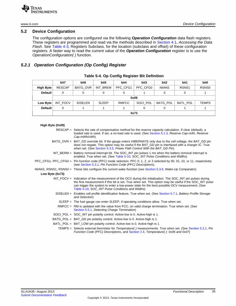
www.ti.com Device Configuration
5.2 Device ConfigurationThe configuration options are configured via the following Operation Configuration data flash registers.These registers are programmed and read via the methods described in Section 4.1, Accessing the DataFlash. See Table 4-3, Registers Subclass, for the location (subclass and offset) of these configurationregisters. A faster way to read the current value of the Operation Configuration register is to use theOperationConfiguration( ) function.
5.2.1 Operation Configuration (Op Config) Register
Table 5-4. Op Config Register Bit Definitionbit7 bit6 bit5 bit4 bit3 bit2 bit1 bit0
High Byte RESCAP BATG_OVR INT_BREM PFC_CFG1 PFC_CFG0 IWAKE RSNS1 RSNS0Default 0 0 0 0 1 0 0 1
0x09Low Byte INT_FOCV IDSELEN SLEEP RMFCC SOCI_POL BATG_POL BATL_POL TEMPS
Default 0 1 1 1 0 0 1 10x73
High Byte (0x09)RESCAP = Selects the rate of compensation method for the reserve capacity calculation. If clear (default), a
loaded rate is used. If set, a no-load rate is used. (See Section 5.1.3, Reserve Cap-mAh, ReserveCap-mWh/cWh)
BATG_OVR = BAT_GD override bit. If the gauge enters HIBERNATE only due to the cell voltage, the BAT_GD pindoes not negate. This option may be useful if the BAT_GD pin is interfaced with a charger IC. Truewhen set. (See Section 5.3.5, Power Path Control With the BAT_GD Pin)
INT_BERM = Battery removal interrupt bit. The SOC_INT pin pulses 1 ms when the battery removal interrupt isenabled. True when set. (See Table 5-10, SOC_INT Pulse Conditions and Widths)
PFC_CFG1, PFC_CFG0 = Pin function code (PFC) mode selection: PFC 0, 1, 2, or 3 selected by 00, 01, 10, or 11, respectively(see Section 5.3.1, Pin Function Code (PFC) Descriptions).
IWAKE, RSNS1, RSNS0 = These bits configure the current wake function (see Section 5.3.6, Wake-Up Comparator).Low Byte (0x73)
INT_FOCV = Indication of the measurement of the OCV during the initialization. The SOC_INT pin pulses duringthe first measurement if this bit is set. True when set. This option may be useful if the SOC_INT pulsecan trigger the system to enter a low-power state for the best possible OCV measurement. (SeeTable 5-10, SOC_INT Pulse Conditions and Widths)
IDSELEN = Enables cell profile identification feature. True when set. (See Section 5.7.1, Battery Profile Storageand Selection)
SLEEP = The fuel gauge can enter SLEEP, if operating conditions allow. True when set.RMFCC = RM is updated with the value from FCC, on valid charge termination. True when set. (See
Section 5.5.1, Detecting Charge Termination)SOCI_POL = SOC_INT pin polarity control. Active-low is 0. Active-high is 1.BATG_POL = BAT_GD pin polarity control. Active-low is 0. Active-high is 1.BATL_POL = BAT_LOW pin polarity control. Active-low is 0. Active-high is 1.
TEMPS = Selects external thermistor for Temperature( ) measurements. True when set. (See Section 5.3.1, PinFunction Code (PFC) Descriptions, and Section 2.4, Temperature( ): 0x06 and 0x07)
35SLUUA35–August 2013 Functional DescriptionSubmit Documentation Feedback
Copyright © 2013, Texas Instruments Incorporated

Device Configuration www.ti.com
5.2.2 Operation Configuration B (OpConfig B) Register
Table 5-5. OpConfig B Register Bit Definitionsbit7 bit6 bit5 bit4 bit3 bit2 bit1 bit0
Byte WRTEMP BIE BL_INT GNDSEL FCE DFWrIndBL RFACTSTEP RSVDDefault 0 1 0 0 1 0 1 0
0x4A
WRTEMP = Enables the temperature write. The temperature is expected to be written by the host and is used forgauging. Neither the external thermistor or internal temperature sensor is used. True when set. (SeeSection 5.3.1, Pin Function Code (PFC) Descriptions, and Section 2.4, Temperature( ): 0x06 and 0x07)
BIE = Battery Insertion Detection feature enable. When enabled, the gauge detects battery insertion using theTS pin. If disabled, the gauge relies on the host to set and clear the Flags( ) [BAT_DET] bit usingBAT_INSERT or BAT_REMOVE subcommands. True when set. (See Section 5.3.3, Battery PresenceDetection Using the BI/TOUT Pin, and Section 5.6.1, BAT INSERT CHECK Mode)
BL_INT = Enables toggle of SOC_INT pin upon the state change of Flags( ) [SOC1] in addition to the BAT_LOWpin's discrete output of the battery low condition. True when set. (See Table 5-10, SOC_INT PulseConditions and Widths)
GNDSEL = The ADC ground select control. The VSS (pin D1) is selected as ground reference when the bit is clear.Pin A1 is selected when the bit is set. The default value is recommend for typical applications.
FCE = Fast Convergence Enable for Resistance Scaling. Configures algorithm to use fast convergence method.The default value is recommend for typical applications. (See Section 5.1.14, Fast Resistance Scaling)
DFWrIndBL = Data Flash Write Indication. SOC_INT pin is used for indication if the bit is clear. BAT_LOW is used forindication if the bit is set.
RFACTSTEP = Enables Ra step up or down to Min/Max Res Factor before disabling Ra updates.RSVD = Bit 0 is reserved.
5.2.3 Operation Configuration C (OpConfig C) Register
Table 5-6. OpConfig C Register Bit Definitionsbit7 bit6 bit5 bit4 bit3 bit2 bit1 bit0
Byte BATGSPUEN RSVD BATLSPUEN RSVD VconsEn SlpWkChg DeltaVOpt1 DeltaVOpt0Default 0 0 1 0 1 1 0 0
0x2C
BATGSPUEN = Enables internal pull-up resistor to VCC (2.5 V) on BAT_GD pin. True when set.RSVD = Bit 6 is reserved.
BATLSPUEN = Enables internal pull-up resistor to VCC (2.5 V) on BAT_LOW pin. True when set.RSVD = Bit 4 is reserved.
VconsEn = Enables Voltage Consistency checking function. Use default value for proper operation.SlpWkChg = Enables compensation for the passed charge missed when waking from SLEEP mode.
DeltaVOpt[1:0] = Configures options for determination of Delta Voltage which is defined as the maximum difference inVoltage( ) during normal load and short load spikes. Delta Voltage is used as a compensation factor forcalculating RemainingCapacity( ) under pulsed loads.00 = Standard DeltaV. Average variance from steady state voltage used to determine end-of-dischargevoltage. (Default)01 = No Averaging. The last instantaneous change in Voltage( ) from steady state determines the end-of-discharge voltage.10 = Use the value in Min Delta Voltage.11 = Not used.
36 Functional Description SLUUA35–August 2013Submit Documentation Feedback
Copyright © 2013, Texas Instruments Incorporated

www.ti.com Device Configuration
5.2.4 Operation Configuration D (OpConfig D) Register
Table 5-7. OpConfig D Register Bit Definitionsbit7 bit6 bit5 bit4 bit3 bit2 bit1 bit0
Byte RCJUMPOK SMTHEN SOC_STATE SOC_OCV SOC_DFW SOC_OT CHGDODEOC RSVDDefault 0 1 0 1 1 1 1 0
0x5E
RCJUMPOK = Allows SOC to change due to a temperature change during relaxation when the SOC smoothingalgorithm is enabled. True when set. (See Section 5.1.16, SOC Smoothing)
SMTHEN = Enables SOC smoothing function. (See Section 5.1.16, SOC Smoothing)SOC_STATE = Enables SOC_INT pin function to generate a pulse due to an Impedance Track™ algorithm state
change.(See Table 5-10, SOC_INT Pulse Conditions and Widths)
SOC_OCV = Enables SOC_INT pin function to generate a pulse due to OCV command. (See Table 5-10, SOC_INTPulse Conditions and Widths)
SOC_DFW = Enables SOC_INT pin function to generate a pulse due to data flash write. (See Table 5-10, SOC_INTPulse Conditions and Widths)
SOC_OT = Enables SOC_INT pin function to generate a pulse due to overtemperature conditions in conjunctionwith the assertion of Flags( ) [OTC or OTD] . (See Table 5-10, SOC_INT Pulse Conditions and Widths)
CHGDODEOC = Enables DoD at End-of-Charge recalculation during charging only. True when set. The default setting isrecommended.
RSVD = Bit 0 is reserved.
5.2.5 Operation Configuration E (OpConfig E) Register
Table 5-8. OpConfig E Register Bit Definitionsbit7 bit6 bit5 bit4 bit3 bit2 bit1 bit0
Byte RSVD RSVD RSVD RSVD DSGFASTQM CHGFASTQM RSVD RSVDDefault 0 0 0 0 0 0 0 0
0x00
RSVD = Bits 7, 6, 5, and 4 are reserved.DSGFASTQM / Enables end of discharge (DSG) / end of charge (CHG) related Fast Qmax function. See Section 5.1.15,
CHGFASTQM = Fast Qmax Update, for additional details. Use the defaults for most applications.RSVD = Bits 1 and 0 are reserved.
37SLUUA35–August 2013 Functional DescriptionSubmit Documentation Feedback
Copyright © 2013, Texas Instruments Incorporated

External Pin Functions www.ti.com
5.3 External Pin Functions
5.3.1 Pin Function Code (PFC) DescriptionsThis fuel gauge has several pin-function configurations available for the end application. Eachconfiguration is assigned a pin function code, or PFC, specified by the Op Config [PFC_CFG1,PFC_CFG0] bits (see Table 5-9). If the fuel gauge is configured to measure external temperature via theOp Config [TEMPS] bit, a voltage bias of approximately 125 ms is applied periodically to the externalthermistor network in order to make a temperature measurement.
Table 5-9. Pin Function Code SummaryExternal Thermistor Bias Rate
([TEMPS] = 1 only)PFC_CFG BAT_GD PinPFC [1:0] Discharge Charge Sleep Usage for PFC Pin Function Description
0 00 1 / s 1 / s 1 / 20 s NA A dedicated external thermistor is used for the fuel gauge to monitorbattery temperature in all conditions. The BAT_GD pin is not used tointerface with a charger IC.
1 01 Temperature- A dedicated external thermistor is used for the fuel gauge to monitorbased Charge battery temperature in all conditions. If battery charging temperature falls
Inhibit outside of the preset range defined in data flash, a charger can bedisabled via the BAT_GD pin until cell temperature recovers. SeeSection 5.5.2, Charge Inhibit and Suspend, for additional details.
2 10 None NA A shared external thermistor is supported between the fuel gauge and acharger IC; however, the BAT_GD pin is not used to interface with thecharger IC. The fuel gauge biases the thermistor for battery temperaturemeasurement and BAT INSERT CHECK mode (if OpConfig B [BIE] bit =1) under discharge and relaxation conditions only so the charger IC canseparately bias the thermistor during charge mode. Bias networksrequired by the fuel gauge and the charger for the thermistor must beidentical.
3 11 1 / s Follows Flags( ) Disables a battery charger IC when fuel gauge has determined the[FC] flags bit battery is fully charged. The BAT_GD pin reflects the logical status of the
Flags( ) [FC] bit and is typically connected directly to the charger ChargeEnable/Disable (CE/CD) pin or via a network to drive the chargerTemperature Sense (TS) pin.
5.3.2 BAT_LOW PinThe BAT_LOW pin provides a system processor with an external indicator of battery status. The signalingon the BAT_LOW pin follows the status of the Flags( ) [SOC1] bit. The BAT_LOW pin polarity isconfigured via the Op Config [BATL_POL] bit. The internal pull-up to VCC (2.5 V) is enabled via theOpConfig C [BATGSPUEN] bit.
5.3.3 Battery Presence Detection Using the BI/TOUT PinDuring power-up or hibernate activities, or any other activity where the fuel gauge needs to determinewhether or not a battery is connected, the fuel gauge applies a test for battery presence when theOpConfig B [BIE] bit is set. First, the BI/TOUT pin is put into high-Z status. The weak 1.8-MΩ pull-upresistor keeps the pin high while no battery is present. When a battery is inserted (or is already inserted)into the system device, the BI/TOUT pin is pulled low. This state is detected by the fuel gauge, which pollsthis pin every second when the gauge has power. A battery-disconnected status is assumed when the fuelgauge reads a thermistor voltage that is near 2.5 V.
When a thermistor is not used by the system for the gauge to detect battery insertion, there are twooptions. First, the BI/TOUT pin can be tied to VSS with a resistor so the gauge always considers a batteryto be present if it has power. Second, the OpConfig B [BIE] bit can be cleared so host can inform thegauge of the battery status via the BAT_INSERT and BAT_REMOVE subcommands.
38 Functional Description SLUUA35–August 2013Submit Documentation Feedback
Copyright © 2013, Texas Instruments Incorporated

www.ti.com External Pin Functions
5.3.4 SOC_INT Pin BehaviorThe SOC_INT pin generates a pulse of different pulse widths under various conditions as indicated byTable 5-10. After initialization, only one SOC_INT pulse is generated within any given one-second timeslot and, therefore, may indicate multiple event conditions.
Table 5-10. SOC_INT Pulse Conditions and WidthsPulse Condition Enable Condition Pulse Width Comment
Change of (SOC Delta) ≠ 0 1 ms During charge, when the SOC is greater than (>) theStateOfCharge( ) points: 100% – n × (SOC Delta) and 100%;
During discharge, when the SOC reaches (≤) the points:100% – n × (SOC Delta) and 0%;where n is an integer starting from 0 to the numbergenerating SOC no less than 0%Examples:For SOC Delta = 1% (default), the SOC_INT intervalsare 0%, 1%, 2%, …, 99%, and 100%.For SOC Delta = 10%, the SOC_INT intervals are 0%,10%, 20%, …, 90%, and 100%.
Change of Flags( ) OpConfig B [BL_INT] = 1 1 ms When SOC reached the SOC1 Set or Clear Threshold[SOC1] state set in the Data Flash.(Set or Clear)Change of Flags( ) Always 1 ms When the Voltage( ) has reached SysDown Set Volt[SYSDOWN] state Threshold or SysDown Clear Volt threshold.(Set or Clear)Battery State Change (SOC Delta) ≠ 0 and 1 ms Upon detection of a state change in battery charging
OpConfig D [SOC_STATE] = 1 and discharging. Relaxation is not included.Battery Removal OpConfig B [BIE] = 1 and 1 ms
Op Config [INT_BREM] = 1OCV measurement Op Config [INT_FOCV] = 1 Approximately Within 1.5 seconds after a POR event or the receipt ofafter initialization 380 ms either BAT_INSERT or RESET subcommand, SOC_INT
begins a pulse for the duration of the OCVmeasurement and initialization time period.
OCV measurement OpConfig D [SOC_OCV] = 1 Approximately Within 1 second after receipt of OCV_CMDfrom OCV_CMD 260 ms subcommand, SOC_INT begins a pulse for the durationsubcommand of the OCV measurement execution time period.After initialization and OpConfig D [SOC_DFW] = 1 Programmable SOC_INT pin indicates the data flash update. TheDF Wr Ind Wait ≠ 0 (see comment) gauge waits DF Wr Ind Wait × 5 μs after the SOC_INT
signal to start the data flash update. This function isdisabled if DF Wr Ind Wait = 0.
Flags( ) [OTC] or OpConfig D [SOC_OT] = 1 1 ms Upon first assertion of Flags( ) [OTC] or [OTD][OTD] overtemperature conditions.
5.3.5 Power Path Control With the BAT_GD PinThe fuel gauge must operate in conjunction with other electronics in a system appliance, such as chargersor other ICs and application circuits that draw appreciable power. After a battery is inserted into thesystem, it is preferable that no charging current or discharging current higher than C/20 is present, so thatan accurate OCV can be read. The OCV helps determine which battery profile to use, as it constitutes partof the battery impedance measurement and determines initial SOC. To disable these functions, theBAT_GD pin can be connected to the Charger Enable/Disable (CE/CD) pin to disable the chargingfunction. Once an OCV reading has been made, the BAT_GD pin is asserted, thereby enabling batterycharging and regular discharge of the battery. The Op Config [BATG_POL] bit can change the polarity ofthe BAT_GD pin in case the default configuration needs to be changed for the system application.
Figure 5-1 and Figure 5-2 detail how the BAT_GD pin functions in the context of battery insertion andremoval, as well as NORMAL versus SLEEP modes.
In PFC 1, the BAT_GD pin also disables battery charging when the fuel gauge reads battery temperaturesoutside the range defined by [Charge Inhibit Temp Low, Charge Inhibit Temp High]. The BAT_GD lineis asserted once temperature falls within the range [Charge Inhibit Temp Low + Temp Hys, ChargeInhibit Temp High – Temp Hys].
39SLUUA35–August 2013 Functional DescriptionSubmit Documentation Feedback
Copyright © 2013, Texas Instruments Incorporated
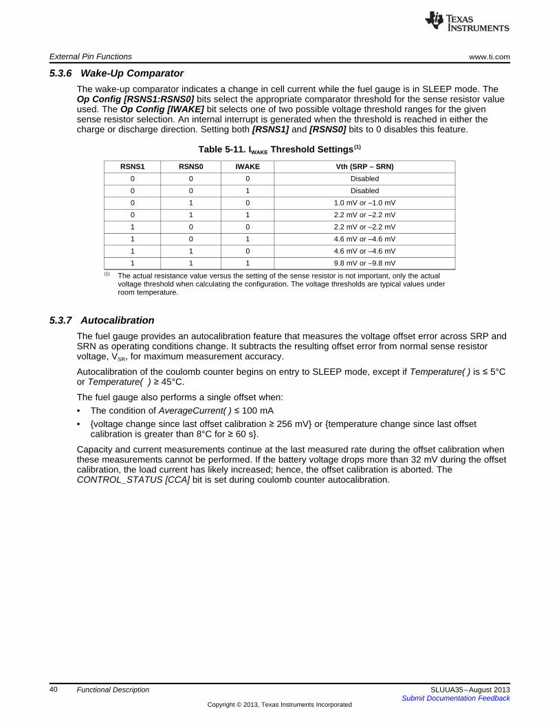
External Pin Functions www.ti.com
5.3.6 Wake-Up ComparatorThe wake-up comparator indicates a change in cell current while the fuel gauge is in SLEEP mode. TheOp Config [RSNS1:RSNS0] bits select the appropriate comparator threshold for the sense resistor valueused. The Op Config [IWAKE] bit selects one of two possible voltage threshold ranges for the givensense resistor selection. An internal interrupt is generated when the threshold is reached in either thecharge or discharge direction. Setting both [RSNS1] and [RSNS0] bits to 0 disables this feature.
Table 5-11. IWAKE Threshold Settings (1)
RSNS1 RSNS0 IWAKE Vth (SRP – SRN)0 0 0 Disabled0 0 1 Disabled0 1 0 1.0 mV or –1.0 mV0 1 1 2.2 mV or –2.2 mV1 0 0 2.2 mV or –2.2 mV1 0 1 4.6 mV or –4.6 mV1 1 0 4.6 mV or –4.6 mV1 1 1 9.8 mV or –9.8 mV
(1) The actual resistance value versus the setting of the sense resistor is not important, only the actualvoltage threshold when calculating the configuration. The voltage thresholds are typical values underroom temperature.
5.3.7 AutocalibrationThe fuel gauge provides an autocalibration feature that measures the voltage offset error across SRP andSRN as operating conditions change. It subtracts the resulting offset error from normal sense resistorvoltage, VSR, for maximum measurement accuracy.
Autocalibration of the coulomb counter begins on entry to SLEEP mode, except if Temperature( ) is ≤ 5°Cor Temperature( ) ≥ 45°C.
The fuel gauge also performs a single offset when:• The condition of AverageCurrent( ) ≤ 100 mA• voltage change since last offset calibration ≥ 256 mV or temperature change since last offset
calibration is greater than 8°C for ≥ 60 s.
Capacity and current measurements continue at the last measured rate during the offset calibration whenthese measurements cannot be performed. If the battery voltage drops more than 32 mV during the offsetcalibration, the load current has likely increased; hence, the offset calibration is aborted. TheCONTROL_STATUS [CCA] bit is set during coulomb counter autocalibration.
40 Functional Description SLUUA35–August 2013Submit Documentation Feedback
Copyright © 2013, Texas Instruments Incorporated

www.ti.com Temperature Measurement
5.4 Temperature MeasurementThe fuel gauge typically measures battery temperature via its TS input to supply battery temperaturestatus information to the fuel gauging algorithm and charger-control sections of the gauge. Alternatively, itcan be configured to use an internal on-chip temperature sensor or receive temperature data from thehost processor. See Section 2.4, Temperature( ): 0x06 and 0x07, for specific information on configurationoptions. Regardless of which temperature configuration is used, the host processor can request thecurrent battery temperature by reading the Temperature( ), and for internal temperature,InternalTemperature( ).
The external thermistor circuit requires the use of an 10K NTC 103AT-type thermistor. Additional circuitinformation for connecting this thermistor to the fuel gauge is shown in Chapter 7, Reference Schematic.
5.4.1 Overtemperature Indication
5.4.1.1 Overtemperature: ChargeIf during charging, Temperature( ) reaches the threshold of OT Chg for a period of OT Chg Time, andAverageCurrent( ) > Chg Current Threshold, then the Flags( ) [OTC] bit is set. When Temperature( )falls to OT Chg Recovery, the Flags( ) [OTC] bit is cleared.
If OT Chg Time = 0, then the feature is completely disabled.
5.4.1.2 Overtemperature: DischargeIf during discharging, Temperature( ) reaches the threshold of OT Dsg for a period of OT Dsg Time, andAverageCurrent( ) ≤ –Dsg Current Threshold, then the Flags( ) [OTD] bit is set. When Temperature( )falls to OT Dsg Recovery, the Flags( ) [OTD] bit is cleared.
If OT Dsg Time = 0, then the feature is completely disabled.
41SLUUA35–August 2013 Functional DescriptionSubmit Documentation Feedback
Copyright © 2013, Texas Instruments Incorporated

Charging and Charge—Termination Indication www.ti.com
5.5 Charging and Charge—Termination Indication
5.5.1 Detecting Charge TerminationFor proper fuel gauge operation, the cell Charging Voltage must be specified by the user. The defaultvalue is specified in Table 4-3, Data Flash Summary—Configuration Class.
The fuel gauge detects charge termination when:• During two consecutive periods of 40 seconds, the AverageCurrent( ) < Taper Current.• During the same two periods, the accumulated change in capacity must be > 0.• Voltage( ) > Charging Voltage – Taper Voltage.
When this occurs, the Flags( ) [CHG] bit is cleared and the Flags( ) [FC] bit is set. Also, if the Op Config[RMFCC] bit is set, then RemainingCapacity( ) is set equal to FullChargeCapacity( ).
5.5.2 Charge Inhibit and SuspendThe fuel gauge can indicate when battery temperature has fallen below or risen above predefinedthresholds Charge Inhibit Temp Low or Charge Inhibit Temp High, respectively. In this mode, theFlags( ) [CHG_INH] bit is set and the BAT_GD pin is deasserted to indicate this condition. The [CHG_INH]bit is cleared and the BAT_GD pin is asserted once the battery temperature returns to the range [ChargeInhibit Temp Low + Temp Hys, Charge Inhibit Temp High – Temp Hys].When PFC = 1, the fuel gauge indicates when battery temperature has fallen below or risen abovepredefined thresholds Suspend Low Temp or Suspend High Temp, respectively. In this mode, theFlags( ) [XCHG] bit is set to indicate this condition. The [XCHG] bit is cleared once the batterytemperature returns to the range [Charge Inhibit Temp Low + Temp Hys, Charge Inhibit Temp High –Temp Hys].The charging should not start when the temperature is below the Charge Inhibit Temp Low or above theCharge Inhibit Temp High. The charging can continue if the charging starts inside the window [ChargeInhibit Temp Low, Charge Inhibit Temp High] until the temperature is either below Suspend Low Tempor above the Suspend High Temp. Therefore, the window [Charge Inhibit Temp Low, Charge InhibitTemp High] must be inside the window of [Suspend Low Temp, Suspend High Temp].
42 Functional Description SLUUA35–August 2013Submit Documentation Feedback
Copyright © 2013, Texas Instruments Incorporated

www.ti.com Power Modes
5.6 Power ModesThe fuel gauge has different power modes: BAT INSERT CHECK, NORMAL, SNOOZE, SLEEP, andHIBERNATE. In NORMAL mode, the fuel gauge is fully powered and can execute any allowable task. InSNOOZE mode, both low-frequency and high-frequency oscillators are active. Although the SNOOZEmode has higher current consumption than the SLEEP mode, it is also a reduced power mode. In SLEEPmode, the fuel gauge turns off the high-frequency oscillator and exists in a reduced-power state,periodically taking measurements and performing calculations. In HIBERNATE mode, the fuel gauge is ina low-power state, but can be woken up by communication or certain IO activity. Finally, the BAT INSERTCHECK mode is a powered up, but low-power halted, state, where the fuel gauge resides when no batteryis inserted into the system.
Figure 5-1 and Figure 5-2 show the relationship between these modes.
43SLUUA35–August 2013 Functional DescriptionSubmit Documentation Feedback
Copyright © 2013, Texas Instruments Incorporated

System Shutdown
HIBERNATE
Disable all bq27520subcircuits except GPIO
Negate BAT_GD
WAIT_HIBERNATE
Fuel gauging and dataupdated every 20 seconds.
unchanged.BAT_GD
Wakeup From HIBERNATECommunication Activity
ANDComm address is not for
bq27520
Exit From WAIT_HIBERNATECell relaxed
ANDAverageCurrent () <
ORCell relaxed
ANDV <
Ι Ι HibernateCurrent
Hibernate VoltageCELL
To SLEEP
POR
BAT INSERT CHECK
Check for battery insertionfrom HALT state.
No gauging
NORMAL
Fuel gauging and dataupdated every second.
Entry To NORMAL[BAT_DET] = 1Flags
Exit From WAIT_HIBERNATEHost must set
= 0AND
CONTROL_STATUS[HIBERNATE]
V <CELL Hibernate Voltage
Exit From SLEEPHost has set
= 1OR
CONTROL_STATUS[HIBERNATE]
V <CELL Hibernate Voltage
Flags [BAT_DET] = 0
Exit From NORMAL[BAT_DET] = 0Flags
Exit From SLEEP[BAT_DET] = 0Flags
Exit From HIBERNATEBattery Removed
Exit From HIBERNATECommunication Activity
AND Comm address is for bq27520
= 0Recommend Host also set
= 0
bq27520 clears CONTROL_STATUS[HIBERNATE]
CONTROL_STATUS[HEBERNATE]
Power Modes www.ti.com
Figure 5-1. Power Mode Diagram for System Shutdown
44 Functional Description SLUUA35–August 2013Submit Documentation Feedback
Copyright © 2013, Texas Instruments Incorporated

POR
BAT INSERT CHECK
Check for battery insertionfrom HALT state.
No gauging
System Sleep
SNOOZE
SLEEP
Fuel gauging and dataupdated every 20 seconds.Both LFO and HFO are ON.
Entry to SLEEP[SNOOZE] = 0CONTROL_STATUS
Exit From HIBERNATEBattery Removed
NORMAL
Fuel gauging and dataupdated every second
Exit From HIBERNATECommunication Activity
AND Comm address is for bq27520
= 0Recommend Host also set
= 0
bq27520 clears CONTROL_STATUS[HIBERNATE]
CONTROL_STATUS[HEBERNATE]
Entry To NORMAL[BAT_DET] = 1Flags
Flags [BAT_DET] = 0
Fuel gauging and dataupdated every 20 seconds.(LFO ON and HFO OFF)
Exit From SLEEPHost has set
= 1OR
CONTROL_STATUS[HIBERNATE]
V <CELL Hibernate Voltage
To WAIT_HIBERNATE
Entry to SNOOZE[SNOOZE] = 1CONTROL_STATUS
Exit From SLEEP>
ORCurrent is detected above
Ι Ι
Ι
AverageCurrent ( ) Sleep Current
WAKE
Exit From SNOOZEAny communication to the gauge
OR>
ORCurrent is detected above
Ι Ι
Ι
AverageCurrent ( ) Sleep Current
WAKE
Exit From NORMAL[BAT_DET] = 0Flags
Exit From WAIT_HIBERNATEHost must set
= 0AND
CONTROL_STATUS[HIBERNATE]
V <CELL Hibernate Voltage
Entry To SNOOZE= 1
AND= 1]
Operation Configuration [SLEEP]
CONTROL_STATUS [SNOOZE]AND
Ι ΙAverageCurrent ( ) < Sleep Current
Entry To SLEEP= 1
AND= 0]
Operation Configuration [SLEEP]
CONTROL_STATUS [SNOOZE]AND
Ι ΙAverageCurrent ( ) < Sleep Current
Exit From SLEEP[BAT_DET] = 0Flags
www.ti.com Power Modes
Figure 5-2. Power Mode Diagram for System Sleep
45SLUUA35–August 2013 Functional DescriptionSubmit Documentation Feedback
Copyright © 2013, Texas Instruments Incorporated

Power Modes www.ti.com
5.6.1 BAT INSERT CHECK ModeThis mode is a halted-CPU state that occurs when an adapter, or other power source, is present to powerthe fuel gauge (and system), yet no battery has been detected. If enabled via the OpConfig B [BIE] bit,the fuel gauge detects battery insertion either through use of the thermistor network or the BI/TOUT pin.Alternatively, the host can use the BAT_INSERT and BAT_REMOVE subcommands to inform the batterypresence or removal status. When battery insertion is detected, a series of initialization activities beginwhich include: OCV measurement, setting the BAT_GD pin, and selecting the appropriate battery profiles.
Some commands, issued by a system processor, can be processed while the fuel gauge is halted in thismode. The gauge wakes up to process the command, then returns to the halted state awaiting batteryinsertion.
5.6.2 NORMAL ModeThe fuel gauge is in NORMAL mode when not in any other power mode. During this mode,AverageCurrent( ), Voltage( ), and Temperature( ) measurements are taken, and the interface data set isupdated. Decisions to change states are also made. This mode is exited by activating a different powermode.
Because the gauge consumes the most power in the NORMAL mode, the Impedance Track™ algorithmminimizes the time the fuel gauge remains in this mode.
5.6.3 SLEEP ModeSLEEP mode is entered automatically if the feature is enabled (Op Config [SLEEP] bit = 1) andAverageCurrent( ) is below the programmable level Sleep Current. Once entry into SLEEP mode hasbeen qualified, but prior to entering it, the fuel gauge performs a coulomb counter autocalibration tominimize offset.
During SLEEP mode, the fuel gauge periodically takes data measurements and updates its data set.However, a majority of its time is spent in an idle condition.
The fuel gauge exits the SLEEP mode if any entry condition is broken, specifically when either:• AverageCurrent( ) rises above Sleep Current.• A current in excess of IWAKE through RSENSE is detected.
In the event that a battery is removed from the system while a charger is present (and powering thegauge), Impedance Track™ updates are not necessary. Hence, the fuel gauge enters a state that checksfor battery insertion and does not continue executing the Impedance Track™ algorithm.
5.6.4 SNOOZE ModeCompared to the SLEEP mode, the SNOOZE mode has the high-frequency oscillator in operation, hencethe communication delay associated with waking up from SLEEP mode can be eliminated. The SNOOZEmode is entered automatically if the feature is enabled (CONTROL_STATUS [SNOOZE] bit = 1) andAverageCurrent( ) is below the programmable level Sleep Current.During SNOOZE mode, the fuel gauge periodically takes data measurements and updates its data set.However, a majority of its time is spent in an idle condition.
The fuel gauge exits the SNOOZE mode if any entry condition is broken, specifically when:• Any communication activity with the gauge.• AverageCurrent( ) rises above Sleep Current.• A current in excess of IWAKE through RSENSE is detected.
46 Functional Description SLUUA35–August 2013Submit Documentation Feedback
Copyright © 2013, Texas Instruments Incorporated
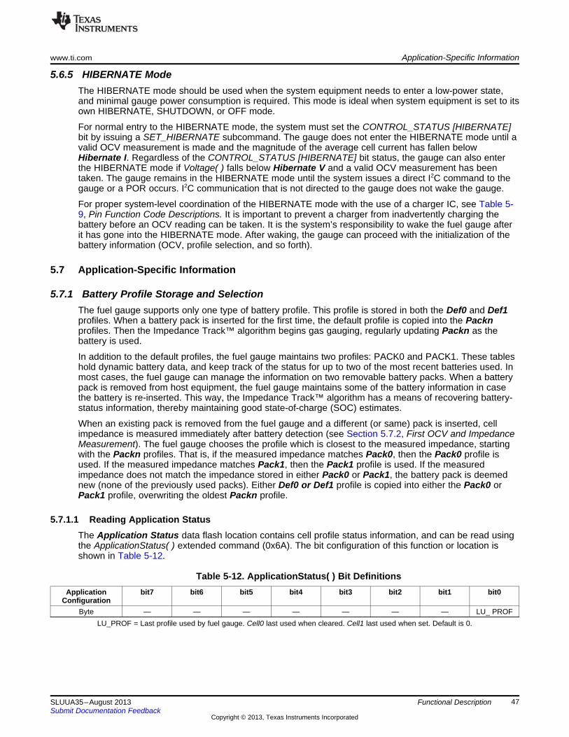
www.ti.com Application-Specific Information
5.6.5 HIBERNATE ModeThe HIBERNATE mode should be used when the system equipment needs to enter a low-power state,and minimal gauge power consumption is required. This mode is ideal when system equipment is set to itsown HIBERNATE, SHUTDOWN, or OFF mode.
For normal entry to the HIBERNATE mode, the system must set the CONTROL_STATUS [HIBERNATE]bit by issuing a SET_HIBERNATE subcommand. The gauge does not enter the HIBERNATE mode until avalid OCV measurement is made and the magnitude of the average cell current has fallen belowHibernate I. Regardless of the CONTROL_STATUS [HIBERNATE] bit status, the gauge can also enterthe HIBERNATE mode if Voltage( ) falls below Hibernate V and a valid OCV measurement has beentaken. The gauge remains in the HIBERNATE mode until the system issues a direct I2C command to thegauge or a POR occurs. I2C communication that is not directed to the gauge does not wake the gauge.
For proper system-level coordination of the HIBERNATE mode with the use of a charger IC, see Table 5-9, Pin Function Code Descriptions. It is important to prevent a charger from inadvertently charging thebattery before an OCV reading can be taken. It is the system’s responsibility to wake the fuel gauge afterit has gone into the HIBERNATE mode. After waking, the gauge can proceed with the initialization of thebattery information (OCV, profile selection, and so forth).
5.7 Application-Specific Information
5.7.1 Battery Profile Storage and SelectionThe fuel gauge supports only one type of battery profile. This profile is stored in both the Def0 and Def1profiles. When a battery pack is inserted for the first time, the default profile is copied into the Packnprofiles. Then the Impedance Track™ algorithm begins gas gauging, regularly updating Packn as thebattery is used.
In addition to the default profiles, the fuel gauge maintains two profiles: PACK0 and PACK1. These tableshold dynamic battery data, and keep track of the status for up to two of the most recent batteries used. Inmost cases, the fuel gauge can manage the information on two removable battery packs. When a batterypack is removed from host equipment, the fuel gauge maintains some of the battery information in casethe battery is re-inserted. This way, the Impedance Track™ algorithm has a means of recovering battery-status information, thereby maintaining good state-of-charge (SOC) estimates.
When an existing pack is removed from the fuel gauge and a different (or same) pack is inserted, cellimpedance is measured immediately after battery detection (see Section 5.7.2, First OCV and ImpedanceMeasurement). The fuel gauge chooses the profile which is closest to the measured impedance, startingwith the Packn profiles. That is, if the measured impedance matches Pack0, then the Pack0 profile isused. If the measured impedance matches Pack1, then the Pack1 profile is used. If the measuredimpedance does not match the impedance stored in either Pack0 or Pack1, the battery pack is deemednew (none of the previously used packs). Either Def0 or Def1 profile is copied into either the Pack0 orPack1 profile, overwriting the oldest Packn profile.
5.7.1.1 Reading Application StatusThe Application Status data flash location contains cell profile status information, and can be read usingthe ApplicationStatus( ) extended command (0x6A). The bit configuration of this function or location isshown in Table 5-12.
Table 5-12. ApplicationStatus( ) Bit DefinitionsApplication bit7 bit6 bit5 bit4 bit3 bit2 bit1 bit0
ConfigurationByte — — — — — — — LU_ PROF
LU_PROF = Last profile used by fuel gauge. Cell0 last used when cleared. Cell1 last used when set. Default is 0.
47SLUUA35–August 2013 Functional DescriptionSubmit Documentation Feedback
Copyright © 2013, Texas Instruments Incorporated

Additional Data Flash Parameter Descriptions www.ti.com
5.7.2 First OCV and Impedance MeasurementUpon power-up or pack insertion an open-circuit voltage (OCV) measurement of the battery is made viathe BAT pin. For best gauging results, the system load during the OCV measurement should not exceed aC/20 discharge rate of the battery. For this first critical measurement, both BAT_GD and SOC_INT pinsare available for system synchronization. (See Section 5.3.5, Power Path Control With the BAT_GD Pin,Section 5.3.4, SOC_INT Pin Behavior, and Section 2.1.6, OCV_CMD: 0x000C.)
Upon completion of the OCV voltage measurement, the CONTROL_STATUS [OCVCMDCOMP] is set.Table 4-6, Data Flash Summary—OCV Table, and the first OCV voltage measurement determine theinitial SOC of the inserted battery, while impedance is computed from subsequent voltage and currentsamples under load using:
Z(SOC) = ( OCV(SOC) – V ) / I.
This impedance is compared with the impedance of the dynamic profiles, Packn, and the default profiles,Defn, for the same SOC. Following all initialization functions, the CONTROL_STATUS [INITCOMP] bit isset.
5.8 Additional Data Flash Parameter Descriptions
5.8.1 TCA Set %TCA Set % is the Terminate Charge Alarm Set Percentage threshold. TCA Set % sets a StateOfCharge( )percentage threshold at which the Flags( ) [CHG] bit is cleared. When TCA Set % is set to –1, it disablesthe use of the charge alarm threshold. When TCA Set % is set to –1 and the taper condition is detected,the [CHG] bit is cleared.
TCA Set % only affects the [CHG] bit but does not affect the charge termination process or the gaugingfunction. The default value is set to 99%.
5.8.2 TCA Clear %TCA Clear % is the Terminate Charge Alarm Clear Percentage threshold. TCA Clear % sets aStateOfCharge( ) percentage level at which the Flags( ) [CHG] bit is set.
TCA Clear % only affects the [CHG] bit but does not affect the charge termination process or the gaugingfunction. The default value is set to 95%.
5.8.3 FC Set %FC Set % is the Full Charge Set Percentage threshold. FC Set % sets a StateOfCharge( ) percentagethreshold at which the Flags( ) [FC] bit is set. When FC Set % is a value other than –1, the [FC] bit is setbased on the amount of passed charge detected by the gauge and not charge termination detection. If FCSet % is set to –1, the [FC] bit is set based on charge termination detection (see Taper Current andTaper Voltage in Section 5.5.1).
FC Set % only affects the [FC] bit which does not affect the charge termination process. The default valueis set to 100%.
5.8.4 FC Clear %FC Clear % is the Full Charge Clear Percentage threshold. FC Clear % sets a StateOfCharge( )percentage threshold at which the Flags( ) [FC] bit is cleared.
FC Clear % only affects the [FC] bit register which does not affect the charge termination process. Thedefault value is set to 98%.
48 Functional Description SLUUA35–August 2013Submit Documentation Feedback
Copyright © 2013, Texas Instruments Incorporated

www.ti.com Additional Data Flash Parameter Descriptions
5.8.5 DOD at EOC Delta TemperatureThis represents the temperature change threshold to update Qstart and RemainingCapacity( ) due totemperature changes. During relaxation and at the start of charging, the remaining capacity is calculatedas RemainingCapacity( ) = FullChargeCapacity( ) – Qstart. As temperature decreases, Qstart can becomemuch smaller than that of the old FullChargeCapacity( ) value, resulting in overestimation ofRemainingCapacity( ). To improve accuracy, FullChargeCapacity( ) is updated whenever the temperaturechange since the last FullChargeCapacity( ) update is greater than DODatEOC Delta T × 0.1ºC.
The default value is 50. Note that the units are a tenth of a °C which means a value of 50 corresponds to5ºC.
5.8.6 Default TemperatureThis is the temperature used to initialize the Temperature( ) register until the host writes a different value ifthe OpConfig B [WRTEMP] bit is set.
5.8.7 Device NameThis is string data that can be a maximum of 7 characters. This field does not affect the operation, nor is itused by the part. It is read by using the extended data command: DeviceName( ) (0x63 through 0x69).
5.8.8 Data Flash VersionThis location can be used to store the data flash configuration version. Version control of golden flash filesused in production is recommended.
5.8.9 SOC1 Set ThresholdSOC1 Set Threshold sets a StateOfCharge( ) percentage threshold used to indicate whenStateOfCharge( ) falls to or below a defined StateOfCharge( ). The SOC1 Set Threshold is typically usedas an initial low StateOfCharge( ) warning. When StateOfCharge( ) falls below the SOC1 Set Threshold,the State of Charge Initial [SOC1] bit in the Flags( ) register is set. The [SOC1] bit is cleared onceStateOfCharge( ) rises above the SOC1 Clear Threshold. If SOC1 Set Threshold is set to –1, then the[SOC1] bit becomes inoperative.
The default value is set to 10%.
5.8.10 SOC1 Clear ThresholdSOC1 Clear Threshold sets a StateOfCharge( ) percentage threshold used to indicate whenStateOfCharge( ) rises above a defined StateOfCharge( ). When StateOfCharge( ) rises above the SOC1Clear Threshold, the State of Charge Initial [SOC1] bit in the Flags( ) register is cleared.
SOC1 Clear Threshold is normally set to 5% above the SOC1 Set Threshold. The default value is set to15%.
5.8.11 Final Voltage and Final Volt TimeIf Voltage( ) is below Final Voltage for at least Final Volt Time (in seconds), then RemainingCapacity( )and StateOfCharge( ) are forced to 0. Final Voltage is usually set to the same value as TerminateVoltage.
5.8.12 Def Avg I Last Run and Def Avg P Last RunThese parameters are not used in the fuel gauge.
5.8.13 Max Res FactorMax percentage (ratio) that an impedance value stored in the Ra table is allowed to change in a singleupdate in the positive direction.
49SLUUA35–August 2013 Functional DescriptionSubmit Documentation Feedback
Copyright © 2013, Texas Instruments Incorporated

Additional Data Flash Parameter Descriptions www.ti.com
The default setting is 15. The algorithm divides the value of this parameter by 10. The upper bound isdetermined by multiplying (Max Res Factor / 10) by the impedance value stored in the Ra table.Therefore, a value of 15 indicates resistance can only change by 50% from the current resistance value inthe positive direction.
5.8.14 Min Res FactorMax percentage (ratio) that an impedance value stored in the Ra table is allowed to change in a singleupdate in the negative direction.
The default setting is 5. The algorithm divides the value of this parameter by 10. The lower bound isdetermined by multiplying (Min Res Factor / 10) by the impedance value stored in the Ra table.Therefore, a value of 5 indicates resistance can only change by 50% from the current resistance value inthe negative direction.
5.8.15 Ra FilterRa table updates are filtered. This is a weighting factor which takes a certain percentage of the previousRa table value and the remaining percentage comes from the newest calculated Ra value. This is toprevent resistances in the Ra table from changing quickly. After this filter has been applied, there is a finalcheck to make sure that the new resistances satisfy both Max Res Factor and Min Res Factor.It is normally set to 800 (80% previous Ra value plus 20% learned Ra value to form new Ra value).
5.8.16 ResRelax TimeThis value is used for Impedance Track™ transient modeling of effective resistance. The resistanceincreases from zero to final value determined by the Ra table as defined by the exponent with timeconstant ResRelax Time during discharge simulation. Default value has been optimized for typical cellbehavior, but could be increased if the gauge is being too conservative at low temperature.
5.8.17 Max Sim Rate, Min Sim RateMaximum and minimum limits for current used in simulation runs. The parameters are functions ofDesignCapacity( ) (that is, C/Max Sim Rate or C/Min Sim Rate).
5.8.18 Transient Factor Charge and DischargeWhen a battery is inserted and the system is powering up, it is possible that current may be flowing at thesame time the gauge is initializing the SOC based on a voltage measurement. The gauge compensatesfor this current flow but the amount of compensation can be adjusted by changing the values of these dataflash parameters. For most cases, the default values are recommended.
5.8.19 Max IR CorrectThe Max IR Correct is a maximum IR correction applied to OCV lookup under load. It only applies to OCVlookup after wakeup with detected charge current when gauge needs to establish capacity baseline, butthe current is already flowing.
5.8.20 Thermal ModelingAt low temperatures the gauge could be overly conservative if it assumes the low temperature will persist.In fact, most systems will self-heat during operation. These thermal modeling parameters can be adjustedto predict the self-heating.
The T Rise constant reflects the level of system heating due to self-heating of the cell during discharge.This number can be measured empirically. It can be adjusted also through experimentation. In general, itcan be increased if the gauge is too conservative at low temperature.
T Time Constant reflects the time constant of system heating due to self-heating of the cell duringdischarge. This number can be measured empirically. It can be adjusted also through experimentation. Ingeneral, it can be decreased if the gauge is too conservative at low temperature.
50 Functional Description SLUUA35–August 2013Submit Documentation Feedback
Copyright © 2013, Texas Instruments Incorporated

www.ti.com Additional Data Flash Parameter Descriptions
5.8.21 Cell 0 and 1 V at Chg TermRecords the voltage reading at the full charge taper termination. This voltage is used to calculateDODatEOC. Essentially this register is updated automatically to learn the true full level of the system orcharger.
5.8.22 Calibration, Data, ID = 104Most of the following values never require modification by the user. They are only modified by theCalibration commands in Calibration mode as explained in the application report: Going to Production withthe bq275xx (SLUA449). For calibration using a host system, see Host System Calibration Method(SLUA640).
CC GainThis is the gain factor for calibrating sense resistor, trace, and internal Coulomb Counter (integratingADC delta-sigma) errors. It is used in the algorithm that reports charge in and discharge out of thebattery through the RemainingCapacity( ) register. The difference between CC Gain and CC Delta isthat the algorithm that reports AverageCurrent( ) cancels out the time base because AverageCurrent( )does not have a time component (it reports in mA) and CC Delta requires a time base for reportingRemainingCapacity( ) (it reports in mAh).
CC DeltaThis is the gain factor for calibrating sense resistor, trace, and internal Coulomb Counter (integratingADC delta-sigma) errors. It is used in the algorithm that reports charge in and discharge out of thebattery through the RemainingCapacity( ) register. The difference between CC Gain and CC Delta isthat the algorithm that reports AverageCurrent( ) cancels out the time base because AverageCurrent( )does not have a time component (it reports in mA) and CC Delta requires a time base for reportingRemainingCapacity( ) (it reports in mAh).
CC OffsetTwo offsets are used for calibrating the offset of the internal Coulomb Counter, board layout, senseresistor, copper traces, and other offsets from the Coulomb Counter readings. CC Offset is thecalibration value that primarily corrects for the offset error of the Coulomb Counter circuitry. The otheroffset calibration is Board Offset and is described next. To minimize external influences when doingCC Offset calibration by automatic CC Offset calibration or CC Offset calibration function inCalibration Mode, an internal short is placed across the SRP and SRN pins inside the fuel gauge. CCOffset is a correction for small noise and errors; therefore, to maximize accuracy, it takes about 20seconds to calibrate the offset. Because it is impractical to do a 20-s offset during production, twodifferent methods have been selected for calibrating CC Offset.(A) The first method is to calibrate CC Offset by putting the fuel gauge in Calibration mode and
initiating the CC Offset function as part of the entire calibration suite. See the application note:Going to Production with the bq275xx (SLUA449) for more information on the Calibration mode.This is a short calibration that is not as accurate as the second method, Board Offset. Its primarypurpose is to calibrate CC Offset enough so that it does not affect any other Coulomb Countercalibrations. This is only intended as a temporary calibration because the automatic calibration,Board Offset, is done the first time the I2C Data and Clock is low for more than 20 seconds, whichis a much more accurate calibration.
(B) During normal Gas Gauge Operation when the I2C clock and data lines are low for more than 5seconds and AverageCurrent( ) is less than Sleep Current in mA, then an automatic CC Offsetcalibration is performed. This takes approximately 16 seconds and is much more accurate than themethod in Calibration mode.
Board OffsetBoard Offset is the second offset register. Its primary purpose is to calibrate everything the CC Offsetdoes not calibrate. This includes board layout, sense resistor, copper trace, and other offsets which areexternal to the fuel gauge chip. The simplified ground circuit design in the fuel gauge requires aseparate board offset for each tested device.
Int Temp Offset
51SLUUA35–August 2013 Functional DescriptionSubmit Documentation Feedback
Copyright © 2013, Texas Instruments Incorporated

Additional Data Flash Parameter Descriptions www.ti.com
The fuel gauge has a temperature sensor built into the IC. The Int Temp Offset is used for calibratingoffset errors in the measurement of the reported Temperature( ) if the internal temperature sensor isused. The gain of the internal temperature sensor is accurate enough that a calibration for gain is notrequired.
Ext Temp OffsetExt Temp Offset is for calibrating the offset of the thermistor connected to the TS1 pin as reported byTemperature( ). The gain of the thermistor is accurate enough that a calibration for gain is not required.
Pack V OffsetPack V Offset is a calibration value that is used to correct for any offset relating to the analog-to-digitalconverter (ADC) cell voltage measurement.
52 Functional Description SLUUA35–August 2013Submit Documentation Feedback
Copyright © 2013, Texas Instruments Incorporated

Host generated
A AS 0ADDR[6:0] CMD[7:0] Sr 1ADDR[6:0] A DATA [7:0] A DATA [7:0] PN. . .
(d) incremental read
A AS 0ADDR[6:0] CMD[7:0] Sr 1ADDR[6:0] A DATA [7:0] PN
(c) 1- byte read
A AS A0 PADDR[6:0] CMD[7:0] DATA [7:0]
(a) 1-byte write (b) quick read
S 1ADDR[6:0] A DATA [7:0] PN
Gauge generated
. . .A AS A0 PADDR[6:0] CMD[7:0] DATA [7:0] DATA [7:0] A A
(e) incremental write
(S = Start , Sr = Repeated Start , A = Acknowledge , N = No Acknowledge , and P = Stop).
Chapter 6SLUUA35–August 2013
Communications
6.1 I2C InterfaceThe bq27520-G4 fuel gauge supports the standard I2C read, incremental read, quick read, one byte write,and incremental write functions. The 7-bit device address (ADDR) is the most significant 7 bits of the hexaddress and is fixed as 1010101. The first 8-bits of the I2C protocol is, therefore, 0xAA or 0xAB for write orread, respectively.
The “quick read” returns data at the address indicated by the address pointer. The address pointer, aregister internal to the I2C communication engine, increments whenever data is acknowledged by the fuelgauge or the I2C master. “Quick writes” function in the same manner and are a convenient means ofsending multiple bytes to consecutive command locations (such as two-byte commands that require twobytes of data)
The following command sequences are not supported:Attempt to write a read-only address (NACK after data sent by master):
Attempt to read an address above 0x6B (NACK command):
6.2 I2C Time OutThe I2C engine releases both SDA and SCL if the I2C bus is held low for 2 seconds. If the fuel gauge washolding the lines, releasing them frees them for the master to drive the lines. If an external condition isholding either of the lines low, the I2C engine enters the low-power sleep mode.
53SLUUA35–August 2013 CommunicationsSubmit Documentation Feedback
Copyright © 2013, Texas Instruments Incorporated

A AS 0ADDR [6:0] CMD [7:0] Sr 1ADDR [6:0] A DATA [7:0] A DATA [7:0] PN
A AS A0 PADDR [6:0] CMD [7:0] DATA [7:0] DATA [7:0] A 66 sm
A AS 0ADDR [6:0] CMD [7:0] Sr 1ADDR [6:0] A DATA [7:0] A DATA [7:0] A
DATA [7:0] A DATA [7:0] PN
Waiting time inserted between incremental 2-byte write packet for a subcommand and reading results
(acceptable for 100 kHz)fSCL £
Waiting time inserted after incremental read
66 sm
66 sm
A AS 0ADDR [6:0] CMD [7:0] Sr 1ADDR [6:0] A DATA [7:0] A DATA [7:0] PN
A AS A0 PADDR [6:0] CMD [7:0] DATA [7:0] 66 sm
Waiting time inserted between two 1-byte write packets for a subcommand and reading results
(required for 100 kHz < f 400 kHz)SCL £
66 sm
A AS A0 PADDR [6:0] CMD [7:0] DATA [7:0] 66 sm
I2C Command Waiting Time www.ti.com
6.3 I2C Command Waiting TimeTo ensure proper operation at 400 kHz, a t(BUF) ≥ 66 μs bus free waiting time must be inserted between allpackets addressed to the fuel gauge. In addition, if the SCL clock frequency (fSCL) is > 100 kHz, useindividual 1-byte write commands for proper data flow control. The following diagram shows the standardwaiting time required between issuing the control subcommand the reading the status result. AnOCV_CMD subcommand requires 1.2 seconds prior to reading the result. For read-write standardcommand, a minimum of 2 seconds is required to get the result updated. For read-only standardcommands, there is no waiting time required, but the host should not issue all standard commands morethan two times per second. Otherwise, the fuel gauge could result in a reset issue due to the expiration ofthe watchdog timer.
6.4 I2C Clock StretchingA clock stretch can occur during all modes of fuel gauge operation. In SLEEP and HIBERNATE modes, ashort clock stretch occurs on all I2C traffic as the device must wake-up to process the packet. In the othermodes (BAT INSERT CHECK, NORMAL, SNOOZE) clock stretching only occurs for packets addressedfor the fuel gauge. The majority of clock stretch periods are small as the I2C interface performs normaldata flow control. However, less frequent yet more significant clock stretch periods may occur as blocks ofData Flash are updated. The following table summarizes the approximate clock stretch duration forvarious fuel gauge operating conditions.
ApproximateGauging Mode Operating Condition or Comment DurationSLEEP Clock stretch occurs at the beginning of all traffic as the device wakes up. 5 msHIBERNATEBAT INSERT Clock stretch occurs within the packet for flow control (after a start bit, ACK or first data bit). 100 µsCHECK, Normal Ra table Data Flash updates. 24 msNORMAL,
Data Flash block writes. 72 msSNOOZERestored Data Flash block write after loss of power. 116 msEnd of discharge Ra table Data Flash update. 144 ms
54 Communications SLUUA35–August 2013Submit Documentation Feedback
Copyright © 2013, Texas Instruments Incorporated
Chapter 7SLUUA35–August 2013
Reference Schematic
55SLUUA35–August 2013 Reference SchematicSubmit Documentation Feedback
Copyright © 2013, Texas Instruments Incorporated

U1
BQ
27520
www.ti.com
Figure 7-1. Reference Schematic
56 Reference Schematic SLUUA35–August 2013Submit Documentation Feedback
Copyright © 2013, Texas Instruments Incorporated

Appendix ASLUUA35–August 2013
Open-Circuit Voltage Measurement Background
The accuracy of the Impedance Track™ (IT) algorithm strongly depends on the accuracy and validity ofthe open-circuit voltage (OCV) measurement taken by fuel gauges that are based on IT technology. Thisappendix describes the process of taking OCV measurements during different events.
A.1 Background• OCV Calculation: OCV (open-circuit voltage) is normally a calculated value because a true
measurement of OCV requires an unloaded and relaxed condition on the battery. Because such anunloaded and completely relaxed condition is not always possible in a real system, the fuel gauge usesmeasured voltage, current, and temperature (VIT) to compute the OCV and as a result of thiscalculation, the state of charge (SOC) of the battery is established or reestablished.
• OCV Qualification Time (QT): The time in which SOC_INT is asserted during an OCV measurementis approximately 165 ms. This is the timeframe in which we test if the VIT measurement is qualified foran OCV calculation. This is not the timeframe in which the actual VIT measurement is taken. Duringthis time, the instantaneous current (adci) is measured. If abs(adci) ≥ DesignCapacity/18, then theOCVFail bit is set. Otherwise, the VIT that we have just measured is qualified and the gauge proceedswith OCV calculation.
• Current Measurement Time (CMT): The time of current is measured – 1 s.• Voltage Measurement Time (VMT): The time of voltage is measured – 125 ms.• Temperature Measurement Time (TMT): The time of temperature is measured – 125 ms.
A.1.1 OCV Qualification and CalculationOCV qualification and calculation (QC) happens under two conditions:• OCV_CMD is sent by the host.• Battery Insert (BI) event is detected.
NOTE: POR causes an immediate BI.
A.1.2 OCV Calculation AssumptionThe current, voltage, and temperature must remain stable during QT, CMT, VMT, and TMT. In every casethat stable VIT is mentioned, the desired stable condition for current is <C/20. If this is not true, error canbe introduced into the OCV Calculation.
A.1.3 OCV TimingThe timing of each step in the OCV sequence is shown in Figure A-1.1. After a POR, voltage, current, and temperature are measured before updating the fuel gauge
parameters.2. Quick voltage and current measurements are taken to qualify OCV VIT conditions.3. Voltage, current, and temperature are measured for subsequent fuel gauge parameters updates.
57SLUUA35–August 2013 Open-Circuit Voltage Measurement BackgroundSubmit Documentation Feedback
Copyright © 2013, Texas Instruments Incorporated

Vbattery
FG Vcc
CC Interrupt
SOC_INT
OCV_CMD
Ibattery
C/18
Voltage (ADC)
Temp (ADC)
Offset cal (ADC)
delay (ADC)
Current (ADC)
Current (CC) Accumulate Accumulate Accumulate Accumulate Accumulate
OCV_FAIL
OCV Complete
FG Parameters Update Update Update Update
RemCap Sim
1 2 3
Background www.ti.com
Figure A-1. OCV Timing Sequences
The green dashed lines indicate the completion of an OCV measurement that has failed due to high loaddetected in current (ADC) measurement, whereas the orange dashed lines indicate the completion of asuccessful OCV measurement, given that the load at the time of measurement was below C/18 rate.
The second OCV measurement (orange line) is a success by qualification standard. However, this is notthe recommended-use case because the current is only lowered during the OCV_INT time (thequalification time). This makes the fuel gauge respond as if this were a pass condition; however, theactual result is not good because the actual VIT measurement used for OCV was taken under high load.
58 Open-Circuit Voltage Measurement Background SLUUA35–August 2013Submit Documentation Feedback
Copyright © 2013, Texas Instruments Incorporated

www.ti.com OCV Timing and OCV_CMD Use Recommendations
A.2 OCV Timing and OCV_CMD Use Recommendations
A.2.1 ACTIVE Mode (Fuel Gauge is not in SLEEP Mode)The VIT measurement used for the OCV calculation is the last VIT measured before the OCV_CMD wasreceived. The VIT value used for the OCV calculation needs to be a stable, not transient value. Beforesending the OCV_CMD, the current must be stable and <C/20 for at least one second. Therecommendations for the OCV_CMD used for active mode is that the VIT remains stable from twoseconds before the OCV_CMD is sent until the end of SOC_INT (see Figure A-2).
Figure A-2. OCV Calculation Based on OCV Command
A.2.2 SLEEP ModeIn SLEEP mode, the fuel gauge measures VIT every 20 s, instead of 1 s. The VIT measurement used forthe OCV calculation is the last VIT measured before the OCV_CMD was received. Sleep current is usuallybelow the OCV current-fail threshold. So, the recommendations for the OCV_CMD sent during SLEEPmode is that the VIT remains stable and below the sleep threshold from the time OCV_CMD is sent untilthe end of SOC_INT.
A.2.3 Initial OCV – PORDuring POR, the VIT measurement used for the OCV calculation and qualification takes place betweenabout 300 ms after POR until the end of SOC_INT. To achieve a good initial OCV measurement afterPOR, the recommendation is to keep VIT stable from POR until the end of SOC_INT (see Figure A-3).
59SLUUA35–August 2013 Open-Circuit Voltage Measurement BackgroundSubmit Documentation Feedback
Copyright © 2013, Texas Instruments Incorporated

OCV Timing and OCV_CMD Use Recommendations www.ti.com
Figure A-3. Initial OCV Taken After POR
60 Open-Circuit Voltage Measurement Background SLUUA35–August 2013Submit Documentation Feedback
Copyright © 2013, Texas Instruments Incorporated
Appendix BSLUUA35–August 2013
Glossary
ACK Acknowledge characterADC Analog-to-digital converterBCA Board calibrationBI Battery insertCC Coulomb counter
CCA Coulomb counter calibrationCE Chip enable
Charge Mode Refers to a mode to where the gauge read AverageCurrent( ) > Chg Current Threshold for at least 1 second.Clear Refers to a bit in a register becoming a logic LOW or 0. The bqEvaluation software (EVSW) represents a clear bit with
the color green.cWh Centiwatt-hourCMT Current measurement timeDF Data flash
Discharge Mode Refers to a mode where the gauge read AverageCurrent( ) < (–)Dsg Current Threshold for at least 1 second.DOD Depth of discharge in percent as related to Qmax. 100% corresponds to empty battery.DOD0 Depth of discharge that was looked up in the DOD (OCV) table based on OCV measurement in relaxed state.EOC End of chargeFC Fully charged
FCC Full charge capacity. Total capacity of the battery compensated for present load current, temperature, and aging effects(reduction in chemical capacity and increase in internal impedance).
FIFO First in, first outFlag This word usually represents a read-only status bit that indicates some action has occurred or is occurring. This bit
typically cannot be modified. The flags are set and cleared automatically by the fuel gauge.FVCA Fast voltage and current acquisitionGPIO General-purpose input outputHDQ High-speed data queue
IC Integrated circuitID IdentificationIO Input or outputIT Impedance Track™I2C Inter-integrated circuit
LDO Low dropoutLSB Least significant bitLT Lifetime
MAC Manufacturer access command or control commandmAh Milliamp-hourMSB Most significant bitmWh Milliwatt-hourNACK Negative acknowledge characterNTC Negative temperature coefficientOCV Open-circuit voltage. Voltage measured on fully-relaxed battery with no load applied.OTC Overtemperature in chargeOTD Overtemperature in dischargePFC Pin function codePOR Power-on resetQmax Maximum chemical capacity
61SLUUA35–August 2013 GlossarySubmit Documentation Feedback
Copyright © 2013, Texas Instruments Incorporated

Appendix B www.ti.com
QC Qualification and calculationQT Qualification time
Relaxation Refers to a mode to where the gauge read AverageCurrent( ) < Quit Current for at least 60 seconds.ModeRM Remaining capacityRW Read or writeSCL Serial clock: programmable serial clock used in the I2C interfaceSDA Serial data: serial data bus in the I2C interfaceSE Shutdown enableSet Refers to a bit in a register becoming a logic HIGH or 1. The bqEvaluation software (EVSW) represents a set bit with the
color red.SOC State-of-charge in percent related to FCCSOC1 State-of-charge initialSOCF State-of-charge final
System The word system is sometimes used in this document. When used, it always means a host system that is consumingcurrent from the battery pack.
TCA Terminate charge alarmTMT Temperature measurement timeTS Temperature status
TTE Time-to-emptyTTF Time-to-fullVIT Voltage, current, temperature
VMT Voltage measurement time
62 Glossary SLUUA35–August 2013Submit Documentation Feedback
Copyright © 2013, Texas Instruments Incorporated

IMPORTANT NOTICE
Texas Instruments Incorporated and its subsidiaries (TI) reserve the right to make corrections, enhancements, improvements and otherchanges to its semiconductor products and services per JESD46, latest issue, and to discontinue any product or service per JESD48, latestissue. Buyers should obtain the latest relevant information before placing orders and should verify that such information is current andcomplete. All semiconductor products (also referred to herein as “components”) are sold subject to TI’s terms and conditions of salesupplied at the time of order acknowledgment.
TI warrants performance of its components to the specifications applicable at the time of sale, in accordance with the warranty in TI’s termsand conditions of sale of semiconductor products. Testing and other quality control techniques are used to the extent TI deems necessaryto support this warranty. Except where mandated by applicable law, testing of all parameters of each component is not necessarilyperformed.
TI assumes no liability for applications assistance or the design of Buyers’ products. Buyers are responsible for their products andapplications using TI components. To minimize the risks associated with Buyers’ products and applications, Buyers should provideadequate design and operating safeguards.
TI does not warrant or represent that any license, either express or implied, is granted under any patent right, copyright, mask work right, orother intellectual property right relating to any combination, machine, or process in which TI components or services are used. Informationpublished by TI regarding third-party products or services does not constitute a license to use such products or services or a warranty orendorsement thereof. Use of such information may require a license from a third party under the patents or other intellectual property of thethird party, or a license from TI under the patents or other intellectual property of TI.
Reproduction of significant portions of TI information in TI data books or data sheets is permissible only if reproduction is without alterationand is accompanied by all associated warranties, conditions, limitations, and notices. TI is not responsible or liable for such altereddocumentation. Information of third parties may be subject to additional restrictions.
Resale of TI components or services with statements different from or beyond the parameters stated by TI for that component or servicevoids all express and any implied warranties for the associated TI component or service and is an unfair and deceptive business practice.TI is not responsible or liable for any such statements.
Buyer acknowledges and agrees that it is solely responsible for compliance with all legal, regulatory and safety-related requirementsconcerning its products, and any use of TI components in its applications, notwithstanding any applications-related information or supportthat may be provided by TI. Buyer represents and agrees that it has all the necessary expertise to create and implement safeguards whichanticipate dangerous consequences of failures, monitor failures and their consequences, lessen the likelihood of failures that might causeharm and take appropriate remedial actions. Buyer will fully indemnify TI and its representatives against any damages arising out of the useof any TI components in safety-critical applications.
In some cases, TI components may be promoted specifically to facilitate safety-related applications. With such components, TI’s goal is tohelp enable customers to design and create their own end-product solutions that meet applicable functional safety standards andrequirements. Nonetheless, such components are subject to these terms.
No TI components are authorized for use in FDA Class III (or similar life-critical medical equipment) unless authorized officers of the partieshave executed a special agreement specifically governing such use.
Only those TI components which TI has specifically designated as military grade or “enhanced plastic” are designed and intended for use inmilitary/aerospace applications or environments. Buyer acknowledges and agrees that any military or aerospace use of TI componentswhich have not been so designated is solely at the Buyer's risk, and that Buyer is solely responsible for compliance with all legal andregulatory requirements in connection with such use.
TI has specifically designated certain components as meeting ISO/TS16949 requirements, mainly for automotive use. In any case of use ofnon-designated products, TI will not be responsible for any failure to meet ISO/TS16949.
Products Applications
Audio www.ti.com/audio Automotive and Transportation www.ti.com/automotive
Amplifiers amplifier.ti.com Communications and Telecom www.ti.com/communications
Data Converters dataconverter.ti.com Computers and Peripherals www.ti.com/computers
DLP® Products www.dlp.com Consumer Electronics www.ti.com/consumer-apps
DSP dsp.ti.com Energy and Lighting www.ti.com/energy
Clocks and Timers www.ti.com/clocks Industrial www.ti.com/industrial
Interface interface.ti.com Medical www.ti.com/medical
Logic logic.ti.com Security www.ti.com/security
Power Mgmt power.ti.com Space, Avionics and Defense www.ti.com/space-avionics-defense
Microcontrollers microcontroller.ti.com Video and Imaging www.ti.com/video
RFID www.ti-rfid.com
OMAP Applications Processors www.ti.com/omap TI E2E Community e2e.ti.com
Wireless Connectivity www.ti.com/wirelessconnectivity
Mailing Address: Texas Instruments, Post Office Box 655303, Dallas, Texas 75265Copyright © 2013, Texas Instruments Incorporated
Related Documents


