SLUU063A June 2003 High Performance Analog bq2060EVM-001 and bq2060EVM-002 SBS 1.1 Battery Management Solution Evaluation Module U s e r's G u id e User's Guide

Welcome message from author
This document is posted to help you gain knowledge. Please leave a comment to let me know what you think about it! Share it to your friends and learn new things together.
Transcript

SLUU063A
June 2003 High Performance Analog
bq2060EVM-001 and bq2060EVM-002 SBS 1.1 Battery Management Solution Evaluation Module
U s e r ' s G u i d e
User's Guide

IMPORTANT NOTICE
Texas Instruments Incorporated and its subsidiaries (TI) reserve the right to make corrections, modifications, enhancements, improvements, and other changes to its products and services at any time and to discontinue any product or service without notice. Customers should obtain the latest relevant information before placing orders and should verify that such information is current and complete. All products are sold subject to TI’s terms and conditions of sale supplied at the time of order acknowledgment. TI warrants performance of its hardware products to the specifications applicable at the time of sale in accordance with TI’s standard warranty. Testing and other quality control techniques are used to the extent TI deems necessary to support this warranty. Except where mandated by government requirements, testing of all parameters of each product is not necessarily performed. TI assumes no liability for applications assistance or customer product design. Customers are responsible for their products and application s using TI components. To minimize the risks associated with customer products and applications, customers should provide adequate design and operating safeguards. TI does not warrant or represent that any license, either express or implied, is granted under any TI patent right, copyright, mask work right, or other TI intellectual property right relating to any combination, machine, or process in which TI products or services are used. Information published by TI regarding third-party products or services does not constitute a license from TI to use such products or services or a warranty or endorsement thereof. Use of such information may require a license from a third party under the patents or other intellectual property of the third party, or a license from TI under the patents or other intellectual property of TI. Reproduction of information in TI data books or data sheets is permissible only if reproduction is without alteration and is accompanied by all associated warranties, conditions, limitations, and notices. Reproduction of this information with alteration is an unfair and deceptive business practice. TI is not responsible or liable for such altered documentation. Resale of TI products or services with statements different form or beyond the parameters stated by TI for that product or service voids all express and any implied warranties for the associated TI product or service and is an unfair and deceptive business practice. TI is not responsible or liable for any such statements. Following are URLs where you can obtain information on other Texas Instruments products & application solutions: Products Applications Amplifiers amplifier.ti.com Audio www.ti.com/audio Data Converters dataconverter.ti.com Automotive www.ti.com/automotive DSP dsp.ti.com Broadband www.ti.com/broadband Interface interface.ti.com Digital Control www.ti.com/digitalcontril Logic logic.ti.com Military www.ti.com/military Power Mgmt power.ti.com Optical Networking www.ti.com/opticalnetwork Microcontrollers microcontroller.ti.com Security www.ti.com/security Telephony www.ti.com/telephony Video & Imaging www.ti.com/video Wireless www.ti.com/wireless Mailing Address: Texas Instruments
Post Office Box 655303 Dallas, Texas 75265
Copyright 2003, Texas Instruments Incorporated

EVM IMPORTANT NOTICE
Texas Instruments (TI) provides the enclosed product(s) under the following conditions:
This evaluation kit being sold by TI is intended for use for ENGINEERING DEVELOPMENT OR EVALUATION PURPOSES ONLY and is not considered by TI to be fit for commercial use. As such, the goods being provided may not be complete in terms of required design–, marketing–, and/or manufacturing–related protective considerations, including product safety measures typically found in the end product incorporating the goods. As a prototype, this product does not fall within the scope of the European Union directive on electromagnetic compatibility and therefore may not meet the technical requirements of the directive.
Should this evaluation kit not meet the specifications indicated in the EVM User’s Guide, the kit may be returned within 30 days from the date of delivery for a full refund. THE FOREGOING WARRANTY IS THE EXCLUSIVE WARRANTY MADE BY SELLER TO BUYER AND IS IN LIEU OF ALL OTHER WARRANTIES, EXPRESSED, IMPLIED, OR STATUTORY, INCLUDING ANY WARRANTY OF MERCHANTABILITY OR FITNESS FOR ANY PARTICULAR PURPOSE.
The user assumes all responsibility and liability for proper and safe handling of the goods. Further, the user indemnifies TI from all claims arising from the handling or use of the goods. Please be aware that the products received may not be regulatory compliant or agency certified (FCC, UL, CE, etc.). Due to the open construction of the product, it is the user’s responsibility to take any and all appropriate precautions with regard to electrostatic discharge.
EXCEPT TO THE EXTENT OF THE INDEMNITY SET FORTH ABOVE, NEITHER PARTY SHALL BE LIABLE TO THE OTHER FOR ANY INDIRECT, SPECIAL, INCIDENTAL, OR CONSEQUENTIAL DAMAGES.
TI currently deals with a variety of customers for products, and therefore our arrangement with the user is not exclusive.
TI assumes no liability for applications assistance, customer product design, software performance, or infringement of patents or services described herein.
Please read the EVM User’s Guide and, specifically, the EVM Warnings and Restrictions notice in the EVM User’s Guide prior to handling the product. This notice contains important safety information about temperatures and voltages. For further safety concerns, please contact the TI application engineer.
Persons handling the product must have electronics training and observe good laboratory practice standards.
No license is granted under any patent right or other intellectual property right of TI covering or relating to any machine, process, or combination in which such TI products or services might be or are used.
Mailing Address: Texas Instruments Post Office Box 655303 Dallas, Texas 75265
Copyright 2003, Texas Instruments Incorporated

EVM WARNINGS AND RESTRICTIONS
It is important to operate this EVM within the input voltage range of 3 V and 25 V, with a maximum voltage drop across the sense resistor of ±250 mV (1-W power dissipation).
Exceeding the specified input range may cause unexpected operation and/or irreversible damage to the EVM. If there are questions concerning the input range, please contact a TI field representative prior to connecting the input power.
Applying loads outside of the specified output range may result in unintended operation and/or possible permanent damage to the EVM. Please consult the EVM User’s Guide prior to connecting any load to the EVM output. If there is uncertainty as to the load specification, please contact a TI field representative.
During normal operation, some circuit components may have case temperatures greater than 60°C. The EVM is designed to operate properly with certain components above 60°C as long as the input and output ranges are maintained. These components include but are not limited to linear regulators, switching transistors, pass transistors, and current sense resistors. These types of devices can be identified using the EVM schematic located in the EVM User’s Guide. When placing measurement probes near these devices during operation, please be aware that these devices may be very warm to the touch.
Mailing Address: Texas Instruments Post Office Box 655303 Dallas, Texas 75265
Copyright 2003, Texas Instruments Incorporated

v
Preface
Read This First
About This Manual
This user’s guide describes the characteristics, operation, and use of the bq2060EVM-001 and bq2060EVM-002 evaluation module (EVM). It covers all pertinent areas involved to properly use the EVM with the devices it supports. The physical PCB layout, schematic diagram, and circuit descriptions are included.
How to Use This Manual
This document contains the following chapters:
Chapter 1—Introduction
Chapter 2—bq2060-Based Circuit Module
Chapter 3—bq2060 Circuit Module Schematic and Performance Specification Summary
Chapter 4—Circuit Module Physical Layout and BoM
Chapter 5—EVM Hardware and Software Setup
Chapter 6—Operation
Related Documents From Texas Instruments
To obtain a copy of any of the following TI documents, call the Texas Instruments Literature Response Center at (800) 477-8924, or the Product Information Center (PIC) at (972) 644-5580. When ordering, identify this manual by its title and literature number. Updated documents can also be obtained through our website at www.ti.com.
Data Sheet: Literature Number:
bq2060 SLUS035
FCC Warning
This equipment is intended for use in a laboratory test environment only. It generates, uses, and can radiate radio frequency energy and has not been tested for compliance with the limits of computing devices pursuant to subpart J of part 15 of FCC rules, which are designed to provide reasonable protection against radio frequency interference. Operation of this equipment in other environments may cause interference with radio communications, in which case the user at his own expense will be required to take whatever measures may be required to correct this interference.

vi
Contents 1 Introduction .................................................................................................................................. 1-1
1.1 bq2060 Evaluation Module.................................................................................................. 1-1 1.2 Features.............................................................................................................................. 1-2 1.3 Kit Contents ........................................................................................................................ 1-2 1.4 Ordering Information ........................................................................................................... 1-2
2 bq2060-Based Circuit Module...................................................................................................... 2-1 2.1 Overview............................................................................................................................. 2-1 2.2 Pin Descriptions .................................................................................................................. 2-1
3 bq2060 Circuit Module Schematic and Performance Specification Summary ......................... 3-1 3.1 Schematic ........................................................................................................................... 3-1 3.2 Performance Specifications of the bq2060 Circuit Module................................................... 3-2
4 Circuit Module Physical Layout and BoM................................................................................... 4-1 4.1 Board Layout....................................................................................................................... 4-1 4.2 Bill of Materials.................................................................................................................... 4-2
5 EVM Hardware and Software Setup ............................................................................................ 5-1 5.1 Software Installation............................................................................................................ 5-1 5.2 Hardware Connection ......................................................................................................... 5-1
6 Operation ...................................................................................................................................... 6-1 6.1 Starting the Program ........................................................................................................... 6-1 6.2 Extended Data Screen ........................................................................................................ 6-3 6.3 Data Logging....................................................................................................................... 6-3 6.4 Setting programmable bq2060 options................................................................................ 6-4 6.5 Calibration of a bq2060 Based Module Using the EV2200-60 Software .............................. 6-9 6.6 Direct Access Communication............................................................................................6-11

vii
Figures Figure 1-1. bq2060EVM............................................................................................................. 1-1 Figure 3-1. bq2060EVM-00X Schematic .................................................................................... 3-1 Figure 4-1. bq2060EVM-00X Layout .......................................................................................... 4-1 Figure 5-1. bq2060 Circuit Module Connection to Li-Ion Cells and System Load/Charger.......... 5-2 Figure 5-2. Circuit Module Connection to NiMH Cells and System Load/Charger ...................... 5-2 Figure 6-1. SBS Data Screen..................................................................................................... 6-1 Figure 6-2. SBS Data Screen –Static Data Window ................................................................... 6-2 Figure 6-3. SBS Extended Data Screen..................................................................................... 6-3 Figure 6-4. Li-Ion EEPROM Data Screen................................................................................... 6-5 Figure 6-5. NiMH EEPROM Data Screen................................................................................... 6-6 Figure 6-6. Read EEPROM Values Screen................................................................................ 6-7 Figure 6-7. EEPROM Values to be Written Screen .................................................................... 6-7 Figure 6-8. EEPROM Data Screen –bq2060 Module Calibration Locations ............................... 6-8 Figure 6-9. VFC Offset Screen................................................................................................... 6-9 Figure 6-10. 3 Cell Li-Ion Calibration Screen.............................................................................. 6-10 Figure 6-11. Pro Screen............................................................................................................. 6-11

viii
Tables Table 1-1. Ordering Information................................................................................................ 1-2 Table 3-1. Performance Specification Summary....................................................................... 3-2 Table 5-1. Circuit Module to EV2200 Connections ................................................................... 5-3 Table 5-2. Circuit Module EEPROM Connector to EV2200 Connections .................................. 5-3 Table 6-1. Example Log File..................................................................................................... 6-4

1-1
Chapter 1
Introduction
1.1 bq2060 Evaluation Module
Figure 1-1. bq2060EVM
This EVM is a complete evaluation system for the bq2060 Battery Management System. The EVM includes one bq2060 circuit module, a current sense resistor, a thermistor, an EV2200 PC Interface Board for Gas Gauge Interface, a PC serial cable, and an EEPROM connector. The latest windows based EV2200-60 PC software can be downloaded from the TI web site. The circuit module includes one bq2060 IC, and all other components on-board necessary to monitor and predict capacity of Li-Ion or Li-Polymer (bq2060EVM-001) or NiMH (bq2060EVM-002) cells. Protection for Li-Ion or Li-Polymer cells is not included on this module. The circuit module connects directly across the cells in a battery. With the EV2200 interface board and software, the user can read the bq2060 data registers, program the chipset for different pack configurations, log cycling data for further evaluation and evaluate the overall functionality of the bq2060 solution under different charge and discharge conditions.
NOTE: For this document, bq2060EVM-00X is used for both the bq2060EVM-001 and the bq2060EVM-002.

1-2
1.2 Features Complete evaluation system for the bq2060 SBS 1.1 compliant advanced gas gauge.
Populated circuit module for quick setup
PC software and interface board for easy evaluation
Software that allows data-logging for system analysis
1.3 Kit Contents
1 bq2060 circuit module
1 EEPROM Interface connector with wires
1 Sense resistor
1 EV2200 PC interface board
1 PC serial cable
1 Set of support documentation
1 Set of evaluation software disks entitled EV2200-60
To download the latest EVM software:
1. Go to www.ti.com
2. Search for bq2060, and open the product folder
3. Click on | Development Tools |
4. Click the appropriate EVM (Li-Ion -001 or NiMH -002) and download the EV2200-60 software under the “Contents” section.
5. Find hardware and software setup guidelines in Chapter 5 of this EVM user’s guide
1.4 Ordering Information
Table 1-1. Ordering Information EVM Part Number Chemistry Configuration Capacity bq2060EVM-001 Li-Ion 3 or 4 cell Any bq2060EVM-002 NiMH 4 to 10 cell Any

2-1
Chapter 2
bq2060-Based Circuit Module
2.1 Overview
The bq2060-based circuit module includes all components required for a complete battery management solution. It includes the bq2060 gas gauge IC, 24LC01 EEPROM and other components to accurately predict and monitor capacity of NiMH, Li-Ion, and Li-Polymer cells.
Contacts on the circuit module provide direct connection to the cells (BAT-, 1P, 2P, 3P, BAT+) and the serial communications port (SMBC, SMBC). The system load and charger connect across PACK+ and PACK-.
The /SAFE output reflects the state of the safety output from the bq2060 and has extra ESD protection just for evaluation purposes.
2.2 Pin Descriptions BAT- Negative connection of first (bottom) cell
1P Positive connection of first (bottom) cell
2P Positive connection of second cell
3P Positive connection of third cell
4P Positive connection of fourth (top) cell
SMBC Serial communication port clock
SMBD Serial communication data port
SAFE bq2060 safety output
PACK- Pack negative terminal
VSS Pack negative terminal
PACK+ Pack positive terminal. Used by bq2060 to derive VCC.

2-2

3-1
Chapter 3
bq2060 Circuit Module Schematic and Performance Specification Summary
3.1 Schematic
The schematic shows the circuit for bq2060 implementation.
Figure 3-1. bq2060EVM-00X Schematic

3-2
3.2 Performance Specifications of the bq2060 Circuit Module
Table 3-1. Performance Specification Summary
Specification Min Typ Max Units Input Voltage Pack+ to Pack- 3.0 25 V Charge and Discharge Current* Note 1 A Note 1: Maximum currents are determined by the value of the sense resistor used. Do not exceed ± 250 mV across sense resistor. For the supplied sense resistor, do not exceed 1 Watt.

4-1
Chapter 4
Circuit Module Physical Layout and BoM
4.1 Board Layout
Figure 4-1. bq2060EVM-00X Layout
4-2
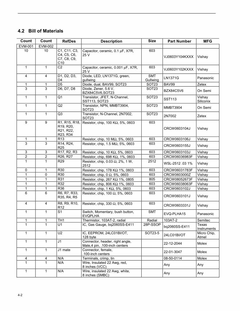
4.2 Bill of Materials
Count Count RefDes Description Size Part Number MFG EVM-001 EVM-002
10 10 C1, C11, C3, C4, C5, C6, C7, C8, C9, C10
Capacitor, ceramic, 0.1 µF, X7R, 25 V
603
VJ0603Y104KXXX Vishay
1 1 C2 Capacitor, ceramic, 0.001 µF, X7R, 25 V
603 VJ0603Y102KXXX Vishay
4 4 D1, D2, D3, D4
Diode, LED, LN1371G, green, gullwing
SMT Gullwing LN1371G Panasonic
1 1 D5 Diode, dual, BAV99, SOT23 SOT23 BAV99 Zetex 3 3 D6, D7, D8 Diode, Zener, 5.6 V,
BZX84C5V6,SOT23 SOT23 BZX84C5V6 On Semi
1 1 Q1 Transistor, JFET, N-Channel, SST113, SOT23
SOT23 SST113 Vishay Siliconix
1 1 Q2 Transistor, NPN, MMBT3904, SOT23
SOT23 MMBT3904 On Semi
1 1 Q3 Transistor, N-Channel, 2N7002, SOT23
SOT23 2N7002 Zetex
9 9 R1, R15, R18, R19, R20, R21, R22, R23, R34
Resistor, chip, 100 KΩ, 5%, 0603 603
CRCW0603104J Vishay
1 1 R13 Resistor, chip, 10 MΩ, 5%, 0603 603 CRCW0603106J Vishay 3 3 R14, R24,
R25 Resistor, chip, 1.5 MΩ, 5%, 0603 603 CRCW0603155J Vishay
3 3 R17, R2, R3 Resistor, chip, 10 KΩ, 5%, 0603 603 CRCW0603103J Vishay 2 2 R26, R27 Resistor, chip, 698 KΩ, 1%, 0603 603 CRCW06036983F Vishay 1 1 R29 Resistor, chip, 0.03 Ω, 2%, 1 W,
2512 2512 WSL-2512 .03 1% Vishay
0 1 R30 Resistor, chip, 178 KΩ 1%, 0603 603 CRCW06031783F Vishay 1 0 R30 Resistor, chip, 0 Ω, 5%, 0603 603 CRCW0603000Z Vishay 1 1 R31 Resistor, chip, 267 KΩ 1%, 0805 805 CRCW08052673F Vishay 1 1 R32 Resistor, chip, 806 KΩ 1%, 0603 603 CRCW06038063F Vishay 1 1 R36 Resistor, chip, 1 KΩ, 5%, 0603 603 CRCW0603102J Vishay 6 6 R6, R7, R33,
R35, R4, R5 Resistor, chip, 100 Ω, 5%, 0603 603
CRCW0603101J Vishay
4 4 R8, R9, R10, R12
Resistor, chip, 330 Ω, 5%, 0603 603 CRCW0603331J Vishay
1 1 S1 Switch, Momentary, bush button, EVQPLHA
SMT EVQ-PLHA15 Panasonic
1 1 TH1 Thermistor, 103AT-2, radial Radial 103AT-2 Semitec 1 1 U1 IC, Gas Gauge, bq2060SS-E411 28P-SSOP bq2060SS-E411 Texas
Instruments 1 1 U2 IC, EEPROM, 24LC01BI/OT,
128 byte SOT23-5 24LC01BI/OT Micro Chip,
Atmel 1 1 J1 Connector, header, right angle,
Male,4 pin, .100-inch centers 22-12-2044 Molex
1 1 J1 mate Connector, female, .100-inch centers
22-01-3047 Molex
4 4 N/A Terminals, crimp, tin 08-50-0114 Molex 1 1 N/A Wire, Insulated 22 Awg, red,
8 inches (VCC) Any Any
1 1 N/A Wire, insulated 22 Awg, white, 8 inches (SMBC)
Any Any

Circuit Module Physical Layout and BoM
4-3
Count Count RefDes Description Size Part Number MFG 1 1 N/A Wire, insulated 22 Awg, black,
8 inches (GND) Any Any
1 1 N/A Wire, insulated 22 Awg, brown, 8 inches (SMBD)
Any Any
1 1 TB1 Terminal block, .200-inch centers, 4 position, 90 deg
ED120/4DS On Shore Technology
1 1 TB2 Terminal block, .200-inch centers, 6 position, 90 deg
ED120/6DS On Shore Technology

4-4

5-1
Chapter 5
EVM Hardware and Software Setup
This chapter describes how to install the bq2060EVM-00X PC software and how to connect the various components on the EVM.
5.1 Software Installation
5.1.1 The following steps install the EV2200-60 software from the included disks:
1. Insert disk 1 into a 3 ½ inch floppy drive.
2. Select the 3 ½ inch drive using My Computer or File Manager.
3. Double-click on the Setup.exe icon.
4. The setup program prompts for the remaining disks and installs a Windows application group.
5.1.2 Use the following steps to install the latest EV2200-60 software downloaded from the TI website listed in Chapter 1, Section 1.2:
1. Unzip the self-extracting EXE file to a temporary directory.
2. Double-click on the Setup.exe icon.
3. Follow the on screen instructions and the setup program will install a Windows application group.
5.2 Hardware Connection
There are four hardware components to the bq2060EVM-00X: the bq2060 circuit module, the EEPROM interface connector, the EV2200 PC interface board, and the PC.
5.2.1 Connecting the bq2060 circuit module to a battery pack
Figures 5-1 and 5-2 show how to connect the bq2060 circuit module to the cells, and system load/charger. The cells should be connected in the following order.
4-Cell Pack: Connect PACK+ and 4P together. BAT-, 4P, 1P, 2P and then 3P (see Chapter 2, Section 2.2 for pin descriptions)
3-Cell Pack: Connect PACK+ and 4P together. BAT-, 4P, 1P, 2P and then connected 4P and 3P together.
2-Cell Pack: Connect PACK+ and 4P together. BAT-, 4P, 1P, 2P and then connected 4P, 3P, and 2P together.
No Individual Cell voltages: If no individual cell voltages are required then Connect PACK+ and 4P together. Then connect BAT-, and then 4P.

5-2
Figure 5-1. bq2060 Circuit Module Connection to Li-Ion Cells and System Load/Charger Load/C
harger
Optional
to SMBD/HDQ1
to SMBC/HDQ2
to VSS
EV2200
Top Cell
BottomCell
E2 VCC
VSS
SDASCL
Figure 5-2. Circuit Module Connection to NiMH Cells and System Load/Charger
Load/Charger
EV2200
Top Cell
BottomCell
Optional
to SMBD/HDQ1
to SMBC/HDQ2
to VSS
E2 VCC
VSS
SDASCL

EVM Hardware and Software Setup
5-3
5.2.2 PC interface connection
1) Configure the hardware interface to the PC by connecting the bq2060-based smart battery (bq2060EVM-00X) to the EV2200 using wire leads according to the following table.
Table 5-1. Circuit Module to EV2200 Connections
bq2060EVM-00X EV2200 SMBD SMBD/HDQ1 SMBC SMBC/HDQ2 PACK- VSS
2) Connect the EEPROM connector to the bq2060EVM-00X and the wire leads of the EEPROM connector to the EV2200 according to the following table.
Table 5-2. Circuit Module EEPROM Connector to EV2200 Connections
bq2060EVM-00X EV2200 VCC E2 VCC
EEPROM data SDA EEPROM Clock SCL
VSS VSS
3) Connect the PC serial cable to the EV2200 and the PC COM port.
The bq2060EVM-00X is now set up for operation.

5-4

6-1
Chapter 6
Operation
This chapter describes the operation of the EVM2200-60 software.
6.1 Starting the Program
Run EV2200-60 from the ‘Start | Programs | Texas Instruments | EV2200-60’ menu sequence. The SBS Data screen appears, and the data fields begin to populate as the indicator scans down the screen. ‘Remaining Capacity’ is highlighted in Figure 6-1. To disable the scan feature select | Options | Poll BQ Registers | Stop |.
Figure 6-1. SBS Data Screen

6-2
This SBS data screen shows the SBS data set, along with additional Static data shown in a box at the bottom right. By clicking on the ‘Read…’ button, the screen changes to show the static data from the bq2060.
Figure 6-2. SBS Data Screen –Static Data Window

Operation
6-3
6.2 Extended Data Screen
The SBS Extended Data Screen has 2 frames. The First frame contains the SBS Extended data that continues scanning from the bq2060 Data Screen. The second frame is for high speed scanning of up to 7 SBS data values. When the | Start Quick Scan | button is clicked, these scans take precedence over all other scanning to get the highest update rate possible.
Figure 6-3. SBS Extended Data Screen
6.3 Data Logging
SBS Data can be logged for further evaluation by using the File | Start Data Log menu options. Then enter the desired file name and click on | SAVE |. A window appears asking for the desired log interval. Select a desired interval and click | CLOSE |. An example of a data log file is below. To stop the data log follow the same sequence. The log file can be customized by clicking on the check box (in the Log column) next to the data fields on the bq2060 Data and Extended screens. All the data fields that are checked are recorded in the log file. It is important to select the desired data fields prior to starting a log because check box updates made after logging starts are ignored.

6-4
Table 6-1. Example Log File
Elapsed Time(s) Temperature Voltage Current Max Error
Remaining Capacity
Full Charge Capacity
2 296.3 10797 0 100 2025 4050
5 296.3 10791 0 100 2025 4050
8 296.3 10800 0 100 2025 4050
10 296.3 10799 0 100 2025 4050
13 296.3 10800 0 100 2025 4050
15 296.3 10802 0 100 2025 4050
18 296.3 10793 0 100 2025 4050
21 296.3 10792 0 100 2025 4050
23 296.3 10794 0 100 2025 4050
26 296.4 10798 0 100 2025 4050
29 296.4 10797 0 100 2025 4050
32 296.4 10791 0 100 2025 4050
34 296.3 10797 0 100 2025 4050
37 296.3 10794 0 100 2025 4050
39 296.3 10797 0 100 2025 4050
42 296.3 10793 0 100 2025 4050
44 296.3 10795 0 100 2025 4050
47 296.3 10791 0 100 2025 4050
6.4 Setting programmable bq2060 options
The EEPROM on the EVM is configured from the factory as an example Li-Ion battery for the bq2060EVM-001, and for an example Nickel battery for the bq2060EVM-002. Special attention should be paid to make sure the settings are correctly changed for the pack, and application for the bq2060 solution being evaluated. This procedure should be done prior to calibrating the module, as described in the following section. The bq2060 must be reset after changing EEPROM data or calibration, for the changes to take effect. To reset the bq2060, click | Options | Initialize Device |.
EEPROM Data cannot be accessed on a sealed bq2060 (Pack Configuration bit 6 is set). To unseal the pack connect the EEPROM connector, and click | Options | Unlock Device|. Be sure to remove power from the device and re-apply to finish the unsealing procedure. To re-seal the part, click | Options | Seal | bq2060 |. Then reset the bq2060 by clicking | Options | Initialize Device |.
IMPORTANT: The correct setting of these options is essential to obtain the best performance. The settings can be configured using the EEPROM Data Screen.

Operation
6-5
Figure 6-4. Li-Ion EEPROM Data Screen

6-6
Figure 6-5. NiMH EEPROM Data Screen
To read all the data from the bq2060 EEPROM, click on | Read |. To write to a selected location click on the desired location, type in the desired data, and hit the ENTER key. After a moment the next location will be highlighted. The entire EEPROM can be written this way.
The EEPROM configuration data can be saved to a file by selecting | File | Store EEPROM |, and entering a file name. An EEPROM file can also be retrieved in this way and written to the bq2060 using the | Write | button.

Operation
6-7
To read the raw hex data in the EEPROM click on | Read EEPROM Contents |. This reads the entire EEPROM contents and displays it in a new window.
Figure 6-6. Read EEPROM Values Screen
To view the raw hex data prior to writing it to the EEPROM click on | EEPROM Values to be Written |. This does not read from the EERPOM but from the locations as they are displayed. It translates all locations to a raw hex EEPROM map that will be displayed in a new window exactly as it would go into the EEPROM once written.
Figure 6-7. EEPROM Values to be Written Screen

6-8
All data required for calibration is also held in the EEPROM for the bq2060, as highlighted in the following figure.
Figure 6-8. EEPROM Data Screen – bq2060 Module Calibration Locations
Calibration Data

Operation
6-9
6.5 Calibration of a bq2060 Based Module Using the EV2200-60 Software
As part of the calibration data there is a VFC Offset tab. The VFC Offset screen offers a simple to use interface for calibrating the Offset of the VFC. There are two different types of offset to choose from.
Figure 6-9. VFC Offset Screen
Default VFC Offset: To select this offset method click on | Start Calibration |. This method will apply an internal short (inside the bq2060) across the sense resistor. With the sense resistor shorted inside the bq2060 there is less chance that an external current can cause a poor offset calculation. This method does not compensate for slight offsets induced by the circuit board.
Alternate VFC Offset: To select this offset method click on | Start Alternate Calibration |. This method does not apply an internal short across the sense resistor. Care must be taken that no current is flowing through the sense resistor. If there is current, the bq2060 applies this current to its calculations, resulting in an inaccurate VFC offset. With no short across the sense resistor, this method compensates for board offset, as long as no current is flowing.
Once calibration is started, the Calibration Started Field displays the time when the calibration was initiated. The Elapsed Time continually updates the amount of time in minutes from the time calibration began.
To abort the offset attempt, click on | Abort |. This halts the offset calculation process and stores a value of 0x003800 into the EEPROM.
If this module is installed on a pack where VCC is present to the bq2060 after disconnecting from the EV2200, then you can click | Continue Calibration Offline | and the bq2060 automatically finishes the calibration, and stores the final result in the EEPROM

6-10
when it is complete. When this option is selected, a popup window appears asking if you wish to seal the pack after the calibration is complete. Click | Yes | to seal the pack after calibration, or | No | to finish calibration without sealing the pack. This also is automatically done by the bq2060 after it completes calibration.
Figure 6-10. 3 Cell Li-Ion Calibration Screen
The Li-Ion Calibration screen differs from the NiMH calibration screen by the individual cell voltages and cell structure. If the Chemistry or Cell Structure fields do not show the proper configuration in their respective fields, then select the bq2060 Data Screen Tab, select | Options | Initialize Device |, wait 5 seconds and then Return to the Calibration Tab.
The Voltage/Temperature and Current/VFC Gain screen has two frames. The top frame is for calibrating Voltage and Temperature. This calibration procedure should be performed prior to the Current/VFC Gain calibration.
To perform the Voltage/Temperature calibration, enter values in the Reference Standard column recorded using a traceable calibrated standard. Be sure to make the voltage measurements at the connections to the bq2060EVM-00X module to get the most accurate results. Also be sure that you add the cells together at each individual cell field for all the cells below it. The Battery Voltage Field should be derived from all the cells added together. If this application does not have individual cell voltage monitoring, then only the Battery Voltage field will be displayed. Enter the temperature in the appropriate field in the Reference Standard column. Click on the | Start | button to finish the Voltage/Temperature calibration.
To perform the Current/VFC Gain calibration, connect a traceable calibrated load to the bq2060EVM-00X module as shown in Figure 5-1 or Figure 5-2. Then enter the Load current in the Reference Standard column and click | Start | to finish the Current/VFC Gain calibration.

Operation
6-11
6.6 Direct Access Communication
The Pro Screen allows direct access to all the memory in the bq2060 including the memory above the SMBus locations provided the bq2060 is unsealed. There is also a scan tool called Dwell that can be useful for scanning a specific location.
Figure 6-11. Pro Screen

6-12
Related Documents