Bozeman Deaconess Health Services Big Sky Medical Center Big Sky, Montana Project Manual Construction Documents Bid Package No. 2 Structural/Underground Rough-In/Building Enclosure April 18, 2014 HGA Architects and Engineers, LLC 202 1 st Avenue SW #200 Rochester, Minnesota 55902-3129 (507) 281-8600 HGA Commission Number 3465-001-00 © 2014 HGA, LLC.

Welcome message from author
This document is posted to help you gain knowledge. Please leave a comment to let me know what you think about it! Share it to your friends and learn new things together.
Transcript

Bozeman Deaconess Health Services Big Sky Medical Center
Big Sky, Montana
Project Manual
Construction Documents Bid Package No. 2
Structural/Underground Rough-In/Building Enclosure
April 18, 2014
HGA Architects and Engineers, LLC 202 1st Avenue SW #200
Rochester, Minnesota 55902-3129 (507) 281-8600
HGA Commission Number 3465-001-00
© 2014 HGA, LLC.


Bozeman Deaconess Health Services Table of Contents Big Sky Medical Center 3465-001-00 (BP-2) April 18, 2014 000110 - 1
000110 TABLE OF CONTENTS
DIVISION 00 PROCUREMENT AND CONTRACTING REQUIREMENTS
000105 Certifications Page 000110 Table of Contents The following procurement and contracting requirements are by Langlas & Associates, Inc. Instructions to Bidders General Requirements for All Bid Packages Index of Bid Packages Individually Numbered Bid Package Scopes Bid Form Preliminary Project Schedule Sample Subcontract Agreement Sample Purchase Agreement General Warranty / Guarantee Request for Information Form AIA Billing Forms Lien Waiver Subcontractor Site Safety Requirements Daily Report Hot Work Permit
DIVISION 01 GENERAL REQUIREMENTS
011100 Summary of Work 012300 Alternates 013300 Submittal Procedures 013310 Submittal Transmittal 014200 References 014339 Mockups 014500 Quality Control 014533 Structural Testing and Special Inspections 016210 Product Options and Substitution Requirements 016211 Substitution Request Form 017324 Anchorage and Sleeving 017700 Closeout Procedures 017800 Closeout Submittals
DIVISION 02 EXISTING CONDITIONS
Not Used DIVISION 03 CONCRETE
031100 Concrete Forming 031500 Concrete Accessories 032000 Concrete Reinforcing 033000 Cast-In-Place Concrete
DIVISION 04 MASONRY
042001 Unit Masonry and Related Materials 044000 Stone Assemblies 047200 Cast Stone Masonry
DIVISION 05 METALS
051200 Structural Steel Framing 053100 Steel Decking 054000 Cold-Formed Metal Framing
DIVISION 06 WOOD, PLASTICS, AND COMPOSITES

Bozeman Deaconess Health Services Table of Contents Big Sky Medical Center 3465-001-00 (BP-2) April 18, 2014 000110 - 2
Not Used DIVISION 07 THERMAL AND MOISTURE PROTECTION
071353 Elastomeric Sheet Waterproofing 071700 Bentonite Waterproofing 072100 Thermal Insulation 072670 Moisture Barrier 074213 Metal Wall Panels 074223 Phenolic Wall Panels 074646 Mineral-Fiber Cement Siding 075305 Adhered Single Ply Membrane Roofing 075307 Mechanically Attached Single Ply Membrane Roof 076210 Prefinished Sheet Metal Flashing and Trim 079000 Joint Protection
DIVISION 08 OPENINGS
084113 Aluminum Entrances and Storefronts 084229 Automatic Entrances 084400 Aluminum Curtain Walls, Windows and Entrances 088000 Glazing 089100 Louvers
DIVISION 09 FINISHES
Not Used DIVISION 10 SPECIALTIES
107113 Exterior Sun Control Devices DIVISION 11 EQUIPMENT
111300 Loading Dock Equipment DIVISION 12 FURNISHINGS
Not Used DIVISION 13 SPECIAL CONSTRUCTION
130541 Seismic Restraint Requirements for Non-Structural Components DIVISION 14 THROUGH 20
Not Used DIVISION 21 FIRE SUPPRESSION
210500 Common Work Results for Fire Suppression 210517 Sleeves and Sleeve Seals for Fire-Suppression Piping 211313 Wet-Pipe Sprinkler Systems
DIVISION 22 PLUMBING
220500 Common Work Results for Plumbing 220517 Sleeves and Sleeve Seals for Plumbing Piping 221116 Domestic Water Piping 221316 Sanitary Waste and Vent Piping 221319 Sanitary Waste Piping Specialties 221413 Facility Storm Drainage Piping 221423 Storm Drainage Piping Specialties 226600 Chemical-Waste Systems for Laboratory and Healthcare Facilities
DIVISION 23 HEATING, VENTILATING, AND AIR-CONDITIONING (HVAC)
231126 Facility Liquefied-Petroleum Gas Piping 238316 Radiant-Heating Hydronic Piping

Bozeman Deaconess Health Services Table of Contents Big Sky Medical Center 3465-001-00 (BP-2) April 18, 2014 000110 - 3
DIVISION 24 THROUGH 25 Not Used
DIVISION 26 ELECTRICAL
260500 Common Work Results for Electrical 260519 Low-Voltage Electrical Power Conductors and Cables 260526 Grounding and Bonding for Electrical Systems 260533 Raceways and Boxes for Electrical Systems 260544 Sleeves and Sleeve Seals for Electrical Raceways and Cabling 264113 Lightning Protection for Structures
END OF SECTION


BIG SKY MEDICAL CENTER BID PACKAGE 2 – STRUCTURAL, BOZEMAN DEACONESS HEALTH SERVICES UNDERGROUND ROUGH-IN, BIG SKY, MONTANA BUILDING ENVELOPE BID SET
Instructions to Bidders
All Bidders interested in supplying product for, and/or performing work on the Big Sky Medical Center located in Big Sky, Montana shall be subject to the requirements contained within the collective Bid Documents, which are outlined below:
1. Bid Addenda, if any. 2. Instructions to Bidders 3. General Requirements for all Bid Packages 4. Individually Numbered Bid Package Scopes 5. Bid Forms 6. Specifications, prepared by Hammel, Green and Abrahamson, Inc., dated 4/18/2014. 7. Plan Drawings, prepared by Hammel, Green and Abrahamson, Inc., dated 4/18/2014.
The designation of responsibility in the scopes of work takes precedence over the designation of responsibility on the drawings or specifications. If any conflict exists between these documents, precedence shall be determined by the order in which they are listed above. For example, if a conflict exists between the Plans and Specifications, Bidder is to follow the Specifications and include such requirements in his/her bid, unless requirements are altered by subsequent Bid Addenda issued during the bidding process. Complete Bid Documents may be obtained via electronic download as follows:
Log onto www.langlas.com Select “Client Log In” in the upper right corner of the web page Enter the case-sensitive password: bp2struct Download all bid documents shown consisting of the project manual, plans, geotechnical report and any
addenda posted to date. Drawings may also be viewed at the following locations: Langlas & Associates, Inc. 1019 E. Main Street, Suite101 Bozeman, MT 59715
Montana-based Builder’s / Plan Exchanges in Bozeman, Billings, Missoula, Great Falls, Helena, and Kalispell.
Printing / reproduction costs of bid documents shall be at Bidder’s expense. During the bidding phase, all questions concerning the project, Bid Documents, bidding process, scope related items, plan discrepancies, pre-bid Requests for Information, product substitutions, etc. shall be directed to the Construction Manager designated below:
Loren Cantrell, Senior Project Manager 1019 E. Main Street, Suite 101 Bozeman, MT 59715 Ph. 406-585-3420 Fax 406-585-4110 e-mail: [email protected]
Bidders shall submit all questions to Construction Manager in writing. Questions will be answered in a timely manner, and may be used to generate Bid Addenda for distribution to all Bidders at the discretion of the Construction Manager, Owner and Design Team. Oral, telephonic, or form of communication other than a formal Bid Addenda shall not be construed as to alter the Bid Documents.

BIG SKY MEDICAL CENTER BID PACKAGE 2 – STRUCTURAL, BOZEMAN DEACONESS HEALTH SERVICES UNDERGROUND ROUGH-IN, BIG SKY, MONTANA BUILDING ENVELOPE BID SET
Bidders shall review all documents carefully and completely before making their bids. A prebid meeting for this bid package will not be conducted. Each prospective bidder shall visit the site to become familiar with existing conditions prior to submitting a bid. Change order requests submitted after the bid as a result of not visiting the site will not be entertained. Bid questions shall be submitted to the Construction Manager no later than May 14, 2014 at 2:00 P.M. (MDT) Questions will be answered in the form of an Addendum and distributed to all known bidders. All questions received after the cut-off time listed above will not be considered. Sealed bids for all scopes of work on this project shall be submitted on the Bid Form(s) provided within this package and are due to the Langlas & Associates – Bozeman office no later than May 21st, 2014, at 2:00 p.m. (MDT). Bids shall be delivered by U.S. Mail, commercial carrier, or by hand to the address shown above and shall be clearly marked as follows:
Bidders Name and Address Project: Big Sky Medical Center – Big Sky, MT Bid Date: {insert bid date according to this publication or subsequent addendum} Bid Package: {insert Individually Numbered Bid Package from Bid Scope on following pages}
Bidders submitting a bid for more than one individual bid scope shall submit such bids separately, one appropriately marked and sealed envelope for each bid. Bids submitted on any form other than the one(s) provided within this package will be rejected. Faxed bids will not be accepted. Faxed modifications to previously received sealed bids are acceptable, may be sent to (406) 585-4110, and shall clearly state the same information as shown above, in addition to indicating Bidders additive or deductive modification to the previously submitted bid. Do not indicate total bid amount on faxed modifications.
Bids shall remain valid for a period of sixty (60) days following the Bid Date and may not be revoked during this time. Bids will be privately opened in the presence of the Construction Manager, Owner, and Architect. Tabulated bid results will be available as soon as possible and will be posted at the office of the Construction Manager. Bids will be evaluated on the basis of the information requested on the Bid Form(s) as well as a post-bid scope and qualifications review by the Construction Manager following tabulation of the bid results. Construction Manager shall make recommendation to the Owner whether or not to accept bids from the apparent low bidders for each individually numbered bid package depending upon Construction Manager’s findings during the qualification process. In the event that Construction Manager recommends against accepting an apparent low bid based on substantiated information and/or Owner elects not to accept such bid, the second bidder will be contacted for scope and qualification review. Such process shall continue until a qualified subcontractor/supplier is recommended by Construction Manager and/or accepted by Owner. The CM and Owner may make such investigations as they deem necessary to determine the ability of the Bidder to perform the work, and the Bidder shall furnish all such information and data for this purpose as may be requested. The CM and the Owner reserve the right to reject any proposal if the evidence submitted by, or the investigation of, such Bidder fails to satisfy the CM and/or the Owner that such Bidder is properly qualified to carry out the obligations of the Subcontract and complete the work contemplated therein. The CM and the Owner reserve the right in awarding subcontracts to consider the competency, responsibility, and suitability of the Bidder, as well as the amount of the proposals. The CM and the Owner also reserve the right to reject any or all proposals, or waive any irregularities or informalities in the proposals received.

BIG SKY MEDICAL CENTER BID PACKAGE 2 – STRUCTURAL, BOZEMAN DEACONESS HEALTH SERVICES UNDERGROUND ROUGH-IN, BIG SKY, MONTANA BUILDING ENVELOPE BID SET
The CM will designate a set of documents as the as-built drawings to be kept on-site. Any changes in work that deviate from the Contract Documents will be expected to be recorded on this set of Documents by the Subcontractor responsible for the scope of work affected. Any changes that the Subcontractor makes that vary from the Contract Documents shall be recorded within a twenty four (24) hour period after the change occurs in the field, by the Subcontractor, on the above mentioned as-built drawings. The as-built drawings will be reviewed weekly by the CM for compliance to this Article. If Documents are not being kept up to date, CM reserves the right to withhold progress payments and/or final payment to the Subcontractor, until the change(s) is (are) recorded in the as-built drawings. The CM shall promptly pay each Subcontractor/Supplier, upon receipt of payment from the Owner, out of the amount paid to the CM on account of such Subcontractor’s/Supplier’s work, the amount to which said Subcontractor/Supplier is entitled. Payment requests shall be submitted on forms provided within these bid documents. Requests submitted on alternate forms will be returned. The CM requires each Subcontractor/Supplier to make prompt payments to its Sub-subcontractors in a similar manner. Joint check agreements may be used, if necessary, and can be accommodated by the CM. Progress and final payment to the Subcontractor/Supplier will only be processed upon receipt of a properly executed pay request from the Subcontractor/Supplier, on the CM’s “AIA G702, AIA G703, Sworn Statement, and interim lien/claim waiver” form (Attached). This pay request must be received by the CM on or before the 25th of the month. Applications received after the 25th of the month will be held unprocessed until the following pay period. Prior to commencing work, Subcontractor shall furnish and thereafter maintain certificates of insurance in accordance with insurance requirements listed within the Subcontract Agreement. Certificates of insurance and the policies represented thereby shall not be cancelled or modified until thirty (30) days after written notice has been given to CM of such cancellation or modification. Required coverage’s shall be maintained without interruption from the date the Subcontractor commences work on the Project until at least the end of the projects warranty period or one year from the date of the Subcontractor’s receipt of final payment whichever is greater. Bid Package No. 2 – General Scope Description The scope provided in Bid Package No. 2 is the general site provisions including, but not limited to the following work:
− Concrete Foundations, Foundation Damp Proofing, Flatwork and Reinforcing Steel − Concrete Unit Masonry and Precast − Stone Veneer Masonry − Structural Steel, Metal Deck and Miscellaneous Steel (Furnish & Install) − Exterior Steel Stud Framing, Sheathing, & Rigid Insulation − Synthetic Wood, Metal Panel Siding, Cement Panel Siding, Soffit, and Fascia Systems (Furnish & Install) − Membrane Roofing, Parapet Caps, and Related Flashing − Glass Curtain Wall, Aluminum Storefront, Aluminum Entrances, and Automatic Entrances − Exterior Louvers − Exterior Sun Control Devices − Underground Plumbing Rough-in, Radiant Tubing and Propane System − Underground Electrical Rough-in
END OF SECTION


BIG SKY MEDICAL CENTER BID PACKAGE 2 – STRUCTURAL, BOZEMAN DEACONESS HEALTH SERVICES UNDERGROUND ROUGH-IN, BIG SKY, MONTANA BUILDING ENVELOPE BID SET
GENERAL REQUIREMENTS FOR ALL BID PACKAGES The following General Requirements apply to ALL bid packages unless specifically modified within an Individually Numbered Bid Package Scope. Bidders shall carefully review and consider the requirements listed below prior to submitting their bid on the Bid Form for their respective scope. Without limiting the scope of work contained within the balance of the Bid Documents, all bidders shall include and/or comply with the following:
1. Bidder shall factor 2013 Montana Prevailing Wage Rates for Building Construction within their Base Bid and any requested Unit Prices or Alternates.
2. Bidder represents and warrants by submissions of a bid that he/she has carefully examined the Construction Documents, any soil test reports, drainage studies, geotechnical or other reports, the Worksite, and that from his/her own investigations, he/she has satisfied himself/herself as to the nature and location of the Work, the character, quality, and quantity of surface and subsurface materials likely to be encountered, the character of equipment and other facilities needed for the performance of the Work, the general and local conditions and all other materials which may in any way affect the Work or its performance. Without Construction Manager’s prior written approval, Bidder shall not be entitled to compensation for costs arising from the Bidders’ failure to visit the site or the Bidder’s failure to thoroughly study and compare all of the Bid Documents prior to submitting a bid.
3. Each Subcontractor shall be required to completely familiarize himself/herself with the plans and specifications, to visit the Work site to completely familiarize himself/herself with existing conditions, and to conduct any other appropriate investigations, inspections, or inquiries prior to submission of a bid or proposal. No increases in Contract Sums shall be allowed for failure to so inspect or investigate.
4. Successful Bidder shall require all construction workers, whether his/her own forces or the forces of lower tier subcontractors to adhere with strict compliance to the Subcontractor Site Safety Requirements document attached herein. Successful Bidder shall also require adequate and appropriate dress and identification of his/her employees, and subcontractors carrying out the Work. No on-site fraternization shall occur between personnel under the Subcontractor’s direct or indirect supervision and the general public while at the jobsite. Failure of an individual to adhere to these standards of conduct shall result in the immediate termination of employment of the offending employee from all construction on any of the Owner’s property. Repeated termination of Subcontractor’s forces, or one serious infraction, can result in the immediate termination of the Subcontract Agreement between the Successful Bidder and the Construction Manager.
5. Successful Bidder releases, indemnifies, and holds harmless the Construction Manager and the Owner for Bidder’s forces’ non-compliance with Owner’s drug-free, alcohol-free, weapon-free, harassment-free, and tobacco-free zones, or Bidder’s forces’ noncompliance with immigration laws or regulations. Any individual found by Construction Manager or Owner to have violated these restrictions is subject to permanent removal from the Project. Successful Bidder shall cooperate with the Construction Manager and the Owner to ensure compliance with these requirements.
6. Radio use on site is at the Project Superintendent’s discretion. In ear or over ear radios/portable music players will not be allowed on the Project site during the performance of the Work.
7. Subcontractor (or lower tier subcontractor) shall park company and personal motor vehicles on Owner’s property only in parking spaces designated for such use by the Owner and/or Construction

BIG SKY MEDICAL CENTER BID PACKAGE 2 – STRUCTURAL, BOZEMAN DEACONESS HEALTH SERVICES UNDERGROUND ROUGH-IN, BIG SKY, MONTANA BUILDING ENVELOPE BID SET
Manager. Any vehicles not parked in the appropriate locations will be towed at the vehicle owner’s sole expense. Parking availability on-site for non-service/passenger vehicles is not guaranteed. If space is unavailable non-service/passenger vehicles shall lawfully park within adjacent nearby public streets.
8. Subcontract Agreements for entities performing work at the site will be issued by the office of Langlas
& Associates, Inc. using the format included at the end of this package. Bidders are encouraged to review this Subcontract Agreement prior to submitting their bids.
9. Subcontractors shall be required to provide insurance coverage as listed within the enclosed
Subcontract Agreement. Bidders are encouraged to review these insurance requirements prior to submitting their bids.
10. Subcontractors shall be bound to Construction Manager under the same terms Construction Manager
is bound to Owner, pursuant to AIA Document A133 – Standard Form of Agreement between Owner and Construction Manager, and AIA Document A201 – General Conditions of the Contract For Construction. (Insurance requirements shall remain as per the Langlas & Associates Subcontract Agreement.) These documents are available for viewing at the office of the Construction Manager or the Owner.
11. Construction scheduling for a particular bid package may overlap between site activities and building
activities.
12. Work will generally progress following the Preliminary Project Schedule included within the Bid Documents. This schedule has been developed to coincide with the Owner’s overall project completion requirements. Subcontractors/Suppliers will be required to execute their work as required to maintain the Project schedule, unless adjusted or modified by Change Order. Untimely work will not be accepted. Prior to and during the course of the Work, Construction Manager reserves the right to modify the Project schedule for the benefit of the Project. Any such modification will be coordinated with Subcontractors and Suppliers and a revised schedule printed for distribution.
13. Subcontractor to provide own layout, permitting, and inspections required to complete all work of the bid package. Layout shall begin from horizontal and vertical controls provided by the Construction Manager.
14. Coordinate construction operations included in various Sections of these Bid Packages to ensure
efficient and orderly installation of each part of the Work. Coordinate construction operations included under different Packages that depend on each other for proper installation, connection, and operation.
i. Schedule construction operations in the sequence required to obtain the best results
where installation of one part of the Work depends on installation of other components, before or after its own installation.
ii. Make provisions to accommodate items scheduled for later installation.
15. Clean up of all debris generated by this work on a DAILY basis. If the Construction Manager
determines that the subcontractor has failed to adhere to the Construction Manager’s high standards of cleanup, the Construction Manager will send written notice of that determination to the subcontractor. Such notice will include a list of the project areas or conditions requiring the subcontractor’s immediate cleanup. If the subcontractor fails or refuses to clean up the project in response to such notice within forty-eight (48) hours after receipt thereof, the Construction Manager shall have the right, without further notice to the subcontractor to hire other firms or persons to clean up the project to the Construction Manager’s satisfaction. The cost of such project cleanup shall be deducted from the Construction Manager’s payment to the subcontractor. Such deductions shall not
BIG SKY MEDICAL CENTER BID PACKAGE 2 – STRUCTURAL, BOZEMAN DEACONESS HEALTH SERVICES UNDERGROUND ROUGH-IN, BIG SKY, MONTANA BUILDING ENVELOPE BID SET
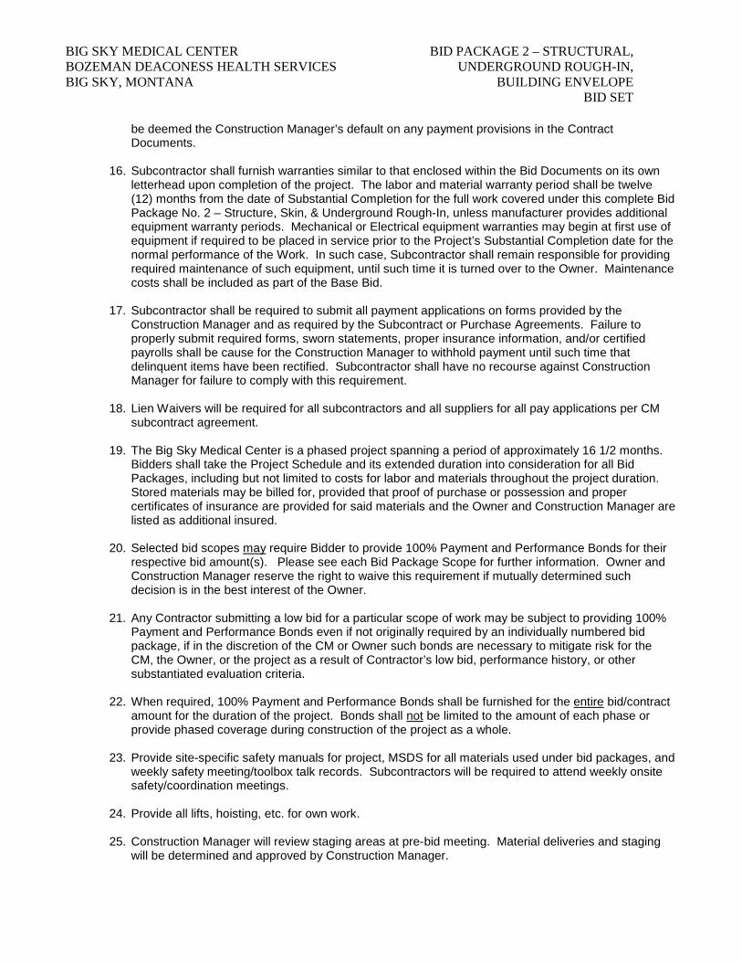
be deemed the Construction Manager’s default on any payment provisions in the Contract Documents.
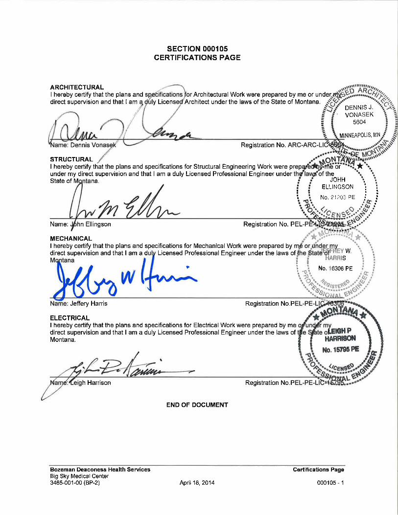
16. Subcontractor shall furnish warranties similar to that enclosed within the Bid Documents on its own letterhead upon completion of the project. The labor and material warranty period shall be twelve (12) months from the date of Substantial Completion for the full work covered under this complete Bid Package No. 2 – Structure, Skin, & Underground Rough-In, unless manufacturer provides additional equipment warranty periods. Mechanical or Electrical equipment warranties may begin at first use of equipment if required to be placed in service prior to the Project’s Substantial Completion date for the normal performance of the Work. In such case, Subcontractor shall remain responsible for providing required maintenance of such equipment, until such time it is turned over to the Owner. Maintenance costs shall be included as part of the Base Bid.
17. Subcontractor shall be required to submit all payment applications on forms provided by the
Construction Manager and as required by the Subcontract or Purchase Agreements. Failure to properly submit required forms, sworn statements, proper insurance information, and/or certified payrolls shall be cause for the Construction Manager to withhold payment until such time that delinquent items have been rectified. Subcontractor shall have no recourse against Construction Manager for failure to comply with this requirement.
18. Lien Waivers will be required for all subcontractors and all suppliers for all pay applications per CM
subcontract agreement.
19. The Big Sky Medical Center is a phased project spanning a period of approximately 16 1/2 months. Bidders shall take the Project Schedule and its extended duration into consideration for all Bid Packages, including but not limited to costs for labor and materials throughout the project duration. Stored materials may be billed for, provided that proof of purchase or possession and proper certificates of insurance are provided for said materials and the Owner and Construction Manager are listed as additional insured.
20. Selected bid scopes may require Bidder to provide 100% Payment and Performance Bonds for their
respective bid amount(s). Please see each Bid Package Scope for further information. Owner and Construction Manager reserve the right to waive this requirement if mutually determined such decision is in the best interest of the Owner.
21. Any Contractor submitting a low bid for a particular scope of work may be subject to providing 100%
Payment and Performance Bonds even if not originally required by an individually numbered bid package, if in the discretion of the CM or Owner such bonds are necessary to mitigate risk for the CM, the Owner, or the project as a result of Contractor’s low bid, performance history, or other substantiated evaluation criteria.
22. When required, 100% Payment and Performance Bonds shall be furnished for the entire bid/contract
amount for the duration of the project. Bonds shall not be limited to the amount of each phase or provide phased coverage during construction of the project as a whole.
23. Provide site-specific safety manuals for project, MSDS for all materials used under bid packages, and weekly safety meeting/toolbox talk records. Subcontractors will be required to attend weekly onsite safety/coordination meetings.
24. Provide all lifts, hoisting, etc. for own work.
25. Construction Manager will review staging areas at pre-bid meeting. Material deliveries and staging will be determined and approved by Construction Manager.

BIG SKY MEDICAL CENTER BID PACKAGE 2 – STRUCTURAL, BOZEMAN DEACONESS HEALTH SERVICES UNDERGROUND ROUGH-IN, BIG SKY, MONTANA BUILDING ENVELOPE BID SET
26. Informational submittals are to be submitted in electronic PDF format as requested by the Construction Manager (Example File Name: e.g. BSMC-BP1-033600.01).
END OF SECTION

BIG SKY MEDICAL CENTER BID PACKAGE 2 – STRUCTURAL, BOZEMAN DEACONESS HEALTH SERVICES UNDERGROUND ROUGH-IN, BIG SKY, MONTANA BUILDING ENVELOPE BID SET
Index of Bid Package No. 2 – Structural, Underground Rough-in, Building Envelope
Individually Numbered Bid
Packages
Bid Package Description
2-1A Temporary Construction Site Fencing 2-3A Concrete Foundations, Flatwork, and Reinforcing Steel 2-4A Concrete Unit Masonry & Precast 2-4B Stone Veneer Masonry 2-5A Structural Steel, Metal Deck and Miscellaneous Steel (Furnish and Install) 2-5B Exterior Steel Stud Framing, Sheathing, Weather Barrier and Rigid Insulation 2-7A Waterproofing 2-7B Synthetic Wood Siding, Metal Panel Siding, Cement Panel Siding, Soffit, and Fascia
Systems 2-7C Membrane Roofing, Parapet Caps, and Related Flashing 2-8A Glass Curtain Wall, Aluminum Storefront, Aluminum Entrances, and Automatic
Entrances 2-8B Exterior Louvers 2-10A Exterior Sun Control Devices 2-11A Loading Dock Equipment 2-22A Underground Plumbing Rough-in, Radiant Tubing and Propane System 2-26A Underground Electrical Rough-in


BIG SKY MEDICAL CENTER BID PACKAGE 2 – STRUCTURAL, BOZEMAN DEACONESS HEALTH SERVICES UNDERGROUND ROUGH-IN, BIG SKY, MONTANA BUILDING ENVELOPE BID SET
Big Sky Medical Center Bid Package No.2-3A – Concrete Foundations, Flatwork, and Reinforcing Steel The narrative description to follow is provided to assist the bidder in determining the various portions of Work related to this Bid Package. It shall in no way limit Bidder’s responsibility to consider all information provided within the complete set of Bid Documents, unless specifically noted to “exclude” a particular item within the text below. The work is described by the complete set of Bid Documents listed in the Instructions to Bidders. Division 00 and Division 01 General Requirements are applicable to all subcontracts. Specification sections specific to this Bid Package are: 031100, 031500, 032000, and 033000 and Geotechnical Report by Dowl HKM dated 11/15/13. The scope of work generally includes, but shall not be limited to the following: SCOPE ITEMS:
1. Construction scheduling for this bid package will overlap between site activities and building activities.
2. Provide footing/foundation drawings in Auto CAD format for review and approval by the CM. Plan will
include footing/foundation, grade beams, pad footings, slab layout, reinforcing, vertical dowel layout, pour sequencing, control joints and all elements required to complete the work of this bid package. Foundation drawings will be required to clearly show elevation changes in grade beams, footings, and walls. Submit drawings to Construction Manager for review one week prior to footing/grade beam excavation to ensure proper excavation elevation is achieved.
3. Contractor is responsible for footing and foundation layout from vertical and horizontal controls
provided by others. Layout shall be performed using “total station” instrument to ensure accuracy with structural steel and framing interfaces.
4. Coordinate layout of all anchor bolts, hold downs, and other embed items with CM prior to placement
to ensure integration with all future framing. All dimensions must be shown on foundation drawing and drawing must be approved by CM before area is scheduled to pour.
5. Set all structural steel anchor bolts as shown through the use of prefabricated anchorbolt templates
furnished and installed as part of this Bid Package scope. Verify accuracy of installed elevation and location of base plate and provide CM a computer generated as-built drawing. Coordinate bolt projection with CM. Structural steel Anchor bolts and base plates furnished by Bid Package 2-5A. All other anchor bolts for wall framing shall be furnished and installed as part of this Bid Package 2-3A. Refer to drawings for requirements.
6. All concrete footings, foundations, interior slab on grade, slab on deck, slab turn downs, piers,
pilasters, and elevator pit, as shown. 7. Include concrete column encasement for entry canopy colummns. Refer to details 1/S250 and
7/S250. Will require coordination CM and Steel Erector. 8. Include 18” diameter piers for trash enclosure at shown on shee A041. Trash enclosure slab and
bollard related concrete is by others under Sitework Bid Package #1. Anchor bolts are provided by others, but installed at time of concrete placement under this Bid Package. Fabricate and install anchor bolt template to ensure proper placement of bolts.

BIG SKY MEDICAL CENTER BID PACKAGE 2 – STRUCTURAL, BOZEMAN DEACONESS HEALTH SERVICES UNDERGROUND ROUGH-IN, BIG SKY, MONTANA BUILDING ENVELOPE BID SET
9. Provide all blockouts as necessary for column baseplates, doorways, sump pits, depressed slab areas and other items as required in the performance of the work. Sleeves for geothermal, plumbing and electrical items shall be provided by respective trades and installed as part of this Bid Package 2-3A scope of work.
10. Coordinate all blockout locations with appropriate trades. Set and secure all blockouts provided by
other trades. Computer generated drawings are required showing all critical blockouts, drawings must be approved by CM one week prior to pour.
11. Includes supply and install of all rebar, rebar chairs, form ties, bracing, and mesh for this bid package.
Include pre-fabricated cages for grade beam rebar. This Bid Pack is responsible for accepting and unloading all rebar deliveries. Include hoisting for own work.
12. Includes all labor and material to complete drilled and epoxied anchors and/or reinforcing for concrete
to concrete connections. 13. Includes supply and install of all smooth dowels and grease, pocket former and diamond plate dowels
shown in contract documents. 14. Supply and install all concrete accessories, including but not limited to 4” void form,
expansion/isolation joint, water stops, chamfer strips, slab key’s, and keyways.
15. Supply 6 sets of rebar shop drawings and 6 sets of final approved rebar fabrication drawings if submitting hard copies. Provide one electronic (PDF Format) shop drawing if submitting electronically.
16. Coordinate and install cast in place electrical grounding with Electrical Contractor prior to placement
of footing concrete. 17. Supply, install, and remove all form material for the bid package.
18. Supply all equipment for own work. Includes but is not limited to concrete pump and forklift for own
work.
19. Wash out of concrete after delivery will be at a pre-determined location on-site. Wash out area is provided by others.
20. Supply and maintain all rebar caps during construction, per OSHA requirements.
21. Includes all concrete materials for own work. 22. Supply full time onsite supervision for own work. 23. Contractor bidding this scope is not allowed to subcontract work without prior written approval of the
CM.
24. Include provisions for concrete blankets, add mixtures, or hot water required at time of placement as can be reasonably be determined from the Preliminary Project Schedule and bidder’s knowledge of local climate conditions. Refer to schedule enclosed with bid documents.
25. Edge of slab at all exterior doors shall be coordinated with door thresholds so as not to protrude
beyond the outside face.
BIG SKY MEDICAL CENTER BID PACKAGE 2 – STRUCTURAL, BOZEMAN DEACONESS HEALTH SERVICES UNDERGROUND ROUGH-IN, BIG SKY, MONTANA BUILDING ENVELOPE BID SET
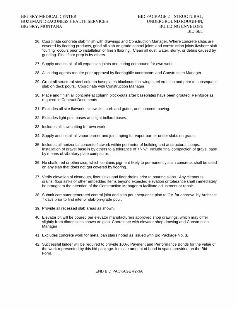
26. Coordinate concrete slab finish with drawings and Construction Manager. Where concrete slabs are covered by flooring products, grind all slab on grade control joints and construction joints if/where slab “curling” occurs prior to installation of finish flooring. Clean all dust, water, slurry, or debris caused by grinding. Final floor prep is by others.
27. Supply and install of all expansion joints and curing compound for own work.
28. All curing agents require prior approval by flooring/tile contractors and Construction Manager. 29. Grout all structural steel column baseplates blockouts following steel erection and prior to subsequent
slab on deck pours. Coordinate with Construction Manager. 30. Place and finish all concrete at column block-outs after baseplates have been grouted. Reinforce as
required in Contract Documents
31. Excludes all site flatwork, sidewalks, curb and gutter, and concrete paving. 32. Excludes light pole bases and light bollard bases.
33. Includes all saw cutting for own work.
34. Supply and install all vapor barrier and joint taping for vapor barrier under slabs on grade.
35. Includes all horizontal concrete flatwork within perimeter of building and at structural stoops. Installation of gravel base is by others to a tolerance of +/- ½”. Include final compaction of gravel base by means of vibratory plate compactor.
36. No chalk, red or otherwise, which contains pigment likely to permanently stain concrete, shall be used on any slab that does not get covered by flooring.
37. Verify elevation of cleanouts, floor sinks and floor drains prior to pouring slabs. Any cleanouts,
drains, floor sinks or other embedded items beyond expected elevation or tolerance shall immediately be brought to the attention of the Construction Manager to facilitate adjustment or repair.
38. Submit computer generated control joint and slab pour sequence plan to CM for approval by Architect
7 days prior to first interior slab-on-grade pour. 39. Provide all recessed slab areas as shown. 40. Elevator pit will be poured per elevator manufacturers approved shop drawings, which may differ
slightly from dimensions shown on plan. Coordinate with elevator shop drawing and Construction Manager.
41. Excludes concrete work for metal pan stairs noted as issued with Bid Package No. 3. 42. Successful bidder will be required to provide 100% Payment and Performance Bonds for the value of
the work represented by this bid package. Indicate amount of bond in space provided on the Bid Form.
END BID PACKAGE #2-3A


BIG SKY MEDICAL CENTER BID PACKAGE 2 – STRUCTURAL, BOZEMAN DEACONESS HEALTH SERVICES UNDERGROUND ROUGH-IN, BIG SKY, MONTANA BUILDING ENVELOPE BID SET
Big Sky Medical Center
Bid Package No.2-4A – Concrete Unit Masonry and Precast The narrative description to follow is provided to assist the bidder in determining the various portions of Work related to this Bid Package. It shall in no way limit Bidder’s responsibility to consider all information provided within the complete set of Bid Documents, unless specifically noted to “exclude” a particular item within the text below. The work is described by the complete set of Bid Documents listed in the Instructions to Bidders. Division 00 and Division 01 General Requirements are applicable to all subcontracts. Specification sections specific to this Bid Package are: 042001, 047200 and 079000 (as applies). Without limiting the Scope of Work described above, Bidders attention is called to the following items which are an integral part of this Bid Package: SCOPE ITEMS:
1. Furnish and install all concrete unit masonry and cast stone masonry work as shown and specified. Excludes Stone Veneer (see Bid Package 2-4B).
2. Include all precast concrete caps. Joints of caps shall be caulked using a sanded or un-sanded caulk in color to match adjacent grout.
3. Include installation of all flashings, through-wall flashings, and drip caps shown within unit masonry work. Flashing material will be furnished by others under separate bid package.
4. Construction Manager will review staging areas. Material deliveries and staging will be determined and approved by Construction Manager.
5. Furnish and install reinforcing steel for masonry walls, as shown. Lay-out and install all loose steel lintels
and embeds unit masonry provided by others under steel Bid Package 3-5A.
6. Provide, install, and remove all necessary shoring and scaffolding to accomplish work of this bid package. Cover top of all walls with non-staining waterproof covering when work is not in progress.
7. Include all winter conditions for own work, if required, including but not limited to tenting, temporary heat,
blankets, etc. Refer to the project schedule.
8. Protect all finished work around and under work area from damage; contractor shall bear financial responsibility for any damage his crew may cause to finished work.
9. Provide, install, and remove rebar caps for own work, per OSHA requirements.
10. Provide, install, and remove safe work zone barricade around own work per OSHA requirements.
11. Clean all unit masonry following installation.
12. Cleanup site and surrounding area of unit masonry spoils and debris. Place in jobsite dumpster provided by Construction Manager.

BIG SKY MEDICAL CENTER BID PACKAGE 2 – STRUCTURAL, BOZEMAN DEACONESS HEALTH SERVICES UNDERGROUND ROUGH-IN, BIG SKY, MONTANA BUILDING ENVELOPE BID SET
END BID PACKAGE #2-4A

BIG SKY MEDICAL CENTER BID PACKAGE 2 – STRUCTURAL, BOZEMAN DEACONESS HEALTH SERVICES UNDERGROUND ROUGH-IN, BIG SKY, MONTANA BUILDING ENVELOPE BID SET
Big Sky Medical Center
Bid Package No.2-4B – Stone Veneer Masonry The narrative description to follow is provided to assist the bidder in determining the various portions of Work related to this Bid Package. It shall in no way limit Bidder’s responsibility to consider all information provided within the complete set of Bid Documents, unless specifically noted to “exclude” a particular item within the text below. The work is described by the complete set of Bid Documents listed in the Instructions to Bidders. Division 00 and Division 01 General Requirements are applicable to all subcontracts. Specification sections specific to this Bid Package are: 044000 and 079000 (as applies). Without limiting the Scope of Work described above, Bidders attention is called to the following items which are an integral part of this Bid Package: SCOPE ITEMS:
1. Furnish and install all stone veneer masonry work as shown and specified.
2. Include installation of all flashings, through-wall flashings, and drip caps shown within stone veneer masonry work. Flashing material will be furnished by others under separate bid package.
3. Construction Manager will review staging areas. Material deliveries and staging will be determined and
approved by Construction Manager.
4. Provide, install, and remove all necessary shoring and scaffolding to accomplish this work. Cover top of all walls with non-staining waterproof covering when work is not in progress as specified.
5. Include all winter conditions for own work if required, including but not limited to tenting, temporary heat,
blankets, etc. See enclosed project schedule for more information.
6. Protect all finished work around and under work area from damage; contractor shall bear financial responsibility for any damage his crew may cause to finished work.
7. Provide, install, and remove safe work zone barricade around own work per OSHA requirements.
8. Clean all stone veneer masonry following installation.
9. Coordinate work under this bid package with unit masonry work under bid package #2-4A.
10. Cleanup site and surrounding area of stone veneer spoils and debris. Place in jobsite dumpster provided by Construction Manager.
END BID PACKAGE #2-4B


BIG SKY MEDICAL CENTER BID PACKAGE 2 – STRUCTURAL, BOZEMAN DEACONESS HEALTH SERVICES UNDERGROUND ROUGH-IN, BIG SKY, MONTANA BUILDING ENVELOPE BID SET
Big Sky Medical Center Bid Package No.2-5A – Structural Steel, Metal Deck and Miscellaneous Steel (Furnish and Install) The narrative description to follow is provided to assist the bidder in determining the various portions of Work related to this Bid Package. It shall in no way limit Bidder’s responsibility to consider all information provided within the complete set of Bid Documents, unless specifically noted to “exclude” a particular item within the text below. The work is described by the complete set of Bid Documents listed in the Instructions to Bidders. Division 00 and Division 01 General Requirements are applicable to all subcontracts. Specification sections specific to this Bid Package are: 051200, 053100 The scope of work generally includes, but shall not be limited to the following: SCOPE ITEMS:
1. Supply submittal shop drawings in accordance with Specification section 013300 to the Construction Manager (CM) for review. Submittals may require separation into different packages to meet delivery and/or erection dates indicated by the Preliminary Project Schedule. The CM must approve separate packages prior to submission by supplier. (example: moment frames embedded in concrete grade beams separate from balance of structure)
2. Maintain a record set of shop drawings in accordance with Specification section 017800. 3. Coordinate construction operations with CM to ensure proper delivery of materials and sequencing of
erection based on the schedule.
4. Furnish all structural steel anchor bolts/connection bolts, base plates, columns, beams, brace frames, moment frames, metal deck, masonry lintels and miscellaneous steel items required by Contract Documents. Includes embedded steel items. Include one set of bolt templates for each unique bolt pattern. All structural steel shall be prime painted, except at interface of metal deck and shear studs or other welded connections. Furnish adequate amount of spray primer to touch up welds after installation.
5. Provide steel erection for all structural steel, metal decking, and misc. steel. Include installation of all deck closure angles and shear studs as required.
6. Excludes steel stairs and handrail shown as part of Bid Package No. 3.
7. Furnish all anchor bolts, washers, leveling nuts, all connection bolts, and anchor bolt drawings for coordination with concrete contractor. Anchor bolts for non-structural steel items shall be by others.
8. Include anchor bolts, tube steel support frame, gate frame, hinges and latch for trash enclosure shown on Sheets A041 and A042. Steel bollards shall be by others under Sitework Bid Package #1.
9. Provide delivery to the job site for all items furnished. Elements, such as the steel moment frames cast in
concrete may require separate shipping from balance of steel package. Phased shipping shall be included as part of the Base Bid for this scope of work. Coordinate with Construction Manager.
10. Furnish all shear studs, metal deck closure angles, closure strips between decking, misc. accessories and
lap screws as required.
BIG SKY MEDICAL CENTER BID PACKAGE 2 – STRUCTURAL, BOZEMAN DEACONESS HEALTH SERVICES UNDERGROUND ROUGH-IN, BIG SKY, MONTANA BUILDING ENVELOPE BID SET
11. All field welding and connections required by the Bid Documents. Includes full penetration welds where shown coordinate with Special Inspector, as required.
12. Preparation of all welds to an appropriate state to receive finish paint and inspection, including Architecturally Exposed Structural Steel, where shown. Touch up prime paint after inspection.
13. Supply and installation of safety railing system along metal deck area perimeter per OSHA requirements. Include removal after permanent protection systems are in place.
14. Furnish and Install bent plate channel jamb shown on detail 6/A462.
15. Supply all hoisting for own work.
16. Successful bidder will be required to provide 100% Payment and Performance Bonds for the value of the work represented by this bid package. Indicate amount of bond in space provided on the Bid Form.
END BID PACKAGE #2-5A

BIG SKY MEDICAL CENTER BID PACKAGE 2 – STRUCTURAL, BOZEMAN DEACONESS HEALTH SERVICES UNDERGROUND ROUGH-IN, BIG SKY, MONTANA BUILDING ENVELOPE BID SET
Big Sky Medical Center
Bid Package No.2-5B – Exterior Steel Stud Framing, Sheathing, Moisture Barrier and Rigid Insulation The narrative description to follow is provided to assist the bidder in determining the various portions of Work related to this Bid Package. It shall in no way limit Bidder’s responsibility to consider all information provided within the complete set of Bid Documents, unless specifically noted to “exclude” a particular item within the text below. The work is described by the complete set of Bid Documents listed in the Instructions to Bidders. Division 00 and Division 01 General Requirements are applicable to all subcontracts. Specification sections specific to this Bid Package are: 054000, 072100 and 72670. Without limiting the Scope of Work described above, Bidders attention is called to the following items which are an integral part of this Bid Package: SCOPE ITEMS:
1. Construction scheduling for this bid package will overlap between site activities and building activities.
2. Work of this bid package includes all labor and materials to complete exterior metal stud framing, exterior sheathing, exterior moisture barrier and exterior rigid insulation.
3. Provide wall framing layout drawings generated in AutoCAD format for all exterior walls. Drawing shall be coordinated with other work of this Bid Package to ensure accuracy with the foundation and structural steel elements. Include all door and window rough openings, louver openings, Z-firring, provide top of wall elevations, structural steel interface, member sizes, headers, clips, and bridging. Submit to Construction Manager a minimum of 10 days prior to starting work for review and approval.
4. Rough opening dimensions will be provided by others.
5. Layout required to complete all work of this bid package. Layout shall begin from horizontal and vertical controls provided by others.
6. Assist Construction Manager in reviewing Structural Steel shop drawings as they relate to framing
members, beam pockets, beam heights, top of wall elevations, etc. for a complete integrated assembly.
7. Repair of any wind damage to work installed under this bid package.
8. Coordinate locating all framing-related embedded anchors with concrete subcontractor. Be present during concrete pours where anchors are being set to ensure proper placement and layout to miss framing members and provide adequate projection of anchor bolts.
9. Supply full time onsite supervision for this scope.
10. Contractor for this bid package is not allowed to subcontract work without prior written approval from the
Construction Manager.
11. Supply and install all fasteners and hardware required for this bid package.
12. Provide all manlifts, forklifts, scaffolding and equipment for own work.
13. Supply, install, and remove all bracing required for own work.
BIG SKY MEDICAL CENTER BID PACKAGE 2 – STRUCTURAL, BOZEMAN DEACONESS HEALTH SERVICES UNDERGROUND ROUGH-IN, BIG SKY, MONTANA BUILDING ENVELOPE BID SET
14. Includes framing of all penetration openings, duct openings, headers, etc. as required. Coordinate with all Mechanical and Electrical trades prior to and during execution of the work.
15. Provide all seismic requirements for own work per plans and local codes.
16. Any framing in conflict with any M/E/P or structural member will be revised to work around those
elements. All revisions are to be included in base bid for this bid package.
17. Properly lap all moisture barriers and flashings during installation to shed moisture at openings from behind finish siding.
END BID PACKAGE #2-5B

BIG SKY MEDICAL CENTER BID PACKAGE 2 – STRUCTURAL, BOZEMAN DEACONESS HEALTH SERVICES UNDERGROUND ROUGH-IN, BIG SKY, MONTANA BUILDING ENVELOPE BID SET
Big Sky Medical Center
Bid Package No.2-7A – Waterproofing The narrative description to follow is provided to assist the bidder in determining the various portions of Work related to this Bid Package. It shall in no way limit Bidder’s responsibility to consider all information provided within the complete set of Bid Documents, unless specifically noted to “exclude” a particular item within the text below. The work is described by the complete set of Bid Documents listed in the Instructions to Bidders. Division 00 and Division 01 General Requirements are applicable to all subcontracts. Specification sections specific to this Bid Package are: 071353 and 071700. Without limiting the Scope of Work described above, Bidders attention is called to the following items which are an integral part of this Bid Package: SCOPE ITEMS:
1. Provide complete job of all elastomeric sheet waterproofing and bentonite waterproofing.
2. Coordinate work schedule with Concrete Contractor, Excavation Contractor and Construction Manager.
END BID PACKAGE #2-7A


BIG SKY MEDICAL CENTER BID PACKAGE 2 – STRUCTURAL, BOZEMAN DEACONESS HEALTH SERVICES UNDERGROUND ROUGH-IN, BIG SKY, MONTANA BUILDING ENVELOPE BID SET
Big Sky Medical Center
Bid Package No.2-7B – Synthetic Wood Siding, Metal Panel Siding, Cement Panel Siding, Soffit, and Fascia Systems
The narrative description to follow is provided to assist the bidder in determining the various portions of Work related to this Bid Package. It shall in no way limit Bidder’s responsibility to consider all information provided within the complete set of Bid Documents, unless specifically noted to “exclude” a particular item within the text below. The work is described by the complete set of Bid Documents listed in the Instructions to Bidders. Division 00 and Division 01 General Requirements are applicable to all subcontracts. Specification sections specific to this Bid Package are: 074213, 074223, 074646, 076210 (as applies) and 079000 (as applies). Without limiting the Scope of Work described above, Bidders attention is called to the following items which are an integral part of this Bid Package: SCOPE ITEMS:
1. A complete job of ALL exterior siding, soffit, fascia, and exterior flashing.
2. Excludes parapet caps, copings and gravel stops at flat roof areas, provided by others via Bid Package 2-7C.
3. Includes detailing, coordination and supply of prefabricated flashing material for unit masonry and stone veneer masonry trades to ensure consistent materials, profiles and finishes throughout. Coordinate with other trades and Construction Manager as necessary. Include cost of separate shipping, if required, to provide flashings during masonry phase, in advance of other siding work. Refer to preliminary project schedule.
4. Include all firring, clips and fasteners as required for attachement of panel systems within this scope of work.
5. Include all blind caulking and sealants required during assembly of systems under this bid package. Exposed caulking/sealant joints required after final installation shall be by others under bid package 2-7D.
6. Provide ground block with cap flashing for mounting exterior items such as wall pack lights, hose bibbs,
and other similar items. Refer to exterior elevations, plumbing and electrical drawings for complete count of these items.
7. Exterior vapor barrier and window wrap shall be provided by others under Bid Package 2-5B.
8. Rain gutter collection boxes and downspouts are furnished and installed by roofing contractor. Coordinate regarding sequence of the work.
9. Include metal siding for trash enclosure as shown on Sheets A041 and A042. Tube steel support is by others. Painting is by others.
10. Exterior masonry is by others.
11. Include all equipment, forklifts, manlifts, scaffolding and safety equipment required for own work.
12. Exterior louvers are by others.
END BID PACKAGE #2-7B


BIG SKY MEDICAL CENTER BID PACKAGE 2 – STRUCTURAL, BOZEMAN DEACONESS HEALTH SERVICES UNDERGROUND ROUGH-IN, BIG SKY, MONTANA BUILDING ENVELOPE BID SET
Big Sky Medical Center
Bid Package No.2-7C – Membrane Roofing, Parapet Caps, and Related Flashing The narrative description to follow is provided to assist the bidder in determining the various portions of Work related to this Bid Package. It shall in no way limit Bidder’s responsibility to consider all information provided within the complete set of Bid Documents, unless specifically noted to “exclude” a particular item within the text below. The work is described by the complete set of Bid Documents listed in the Instructions to Bidders. Division 00 and Division 01 General Requirements are applicable to all subcontracts. Specification sections specific to this Bid Package are: 075305, 075307, 076210 (as applies), and 07 9000 (as applies). Without limiting the Scope of Work described above, Bidders attention is called to the following items which are an integral part of this Bid Package: SCOPE ITEMS:
3. Provide complete job of all membrane roof surfaces, roof walk pads, parapet caps, flashing, sealants, etc. as required for a complete water tight roof/roof deck assembly. Detailing shall be per plan and/or as required for complete, weather tight and warrantable system whether or not specifically detailed.
4. Terminate to roof drains provided by others.
5. Coordinate flashing requirements with Construction Manager, siding contractor and storefront contractor to ensure proper sequencing of the work.
6. During installation of roofing, Contractor shall make every effort to coordinate and protect roof area from
damage by all trades. This shall include monitoring of other Contractors’ equipment and procedures to prevent such damage. If damage occurs and the responsible party is not identified, the Roofing Contractor shall repair all damaged areas. Other trades must be permitted to finish required work after installation of roofing.
7. Include $3,000 allowance for roof repairs as directed by the Construction Manager. Unused portions of
this allowance shall be credited back to the owner at completion of the Project.
8. Provide metal scupper and downspouts where shown.
9. Include mobilizations, manpower and winter construction methods (including snow removal) as may be required for the completion of the work according to the preliminary project schedule (enclosed) as part of the Base Bid.
END BID PACKAGE #2-7C


BIG SKY MEDICAL CENTER BID PACKAGE 2 – STRUCTURAL, BOZEMAN DEACONESS HEALTH SERVICES UNDERGROUND ROUGH-IN, BIG SKY, MONTANA BUILDING ENVELOPE BID SET
Big Sky Medical Center
Bid Package No.2-7D – Caulking and Sealants The narrative description to follow is provided to assist the bidder in determining the various portions of Work related to this Bid Package. It shall in no way limit Bidder’s responsibility to consider all information provided within the complete set of Bid Documents, unless specifically noted to “exclude” a particular item within the text below. The work is described by the complete set of Bid Documents listed in the Instructions to Bidders. Division 00 and Division 01 General Requirements are applicable to all subcontracts. Specification sections specific to this Bid Package are: 079000 Without limiting the Scope of Work described above, Bidders attention is called to the following items which are an integral part of this Bid Package: SCOPE ITEMS:
1. Provide complete job of all exterior backer rod, caulking and sealants for exposed joint surfaces specified and shown for exterior building skin systems with the following being the only exceptions:
a. Blind caulking or sealants installed as part of skin system and inaccessible after system installation.
b. All caulking and sealants that are an integral part of exterior storefront, curtainwall and aluminum entrances; as well as caulking/sealant from these systems to adjacent surfaces.
c. Horizontal caulking for site concrete
d. Caulking related to roofing or roof flashings.
e. Interior caulking or sealants.
f. Sealant shown between cast stone sill and cast stone wall surface on details 6 and 10 A471 and similar.
END BID PACKAGE #2-7D


BIG SKY MEDICAL CENTER BID PACKAGE 2 – STRUCTURAL, BOZEMAN DEACONESS HEALTH SERVICES UNDERGROUND ROUGH-IN, BIG SKY, MONTANA BUILDING ENVELOPE BID SET
Big Sky Medical Center
Bid Package No.2-8A – Glass Curtain Wall, Aluminum Storefront, Aluminum Entrances, and Automatic Entrances The narrative description to follow is provided to assist the bidder in determining the various portions of Work related to this Bid Package. It shall in no way limit Bidder’s responsibility to consider all information provided within the complete set of Bid Documents, unless specifically noted to “exclude” a particular item within the text below. The work is described by the complete set of Bid Documents listed in the Instructions to Bidders. Division 00 and Division 01 General Requirements are applicable to all subcontracts. Specification sections specific to this Bid Package are: 079000 (as applies), 084113, 084229, 084400, and 088000. Without limiting the Scope of Work described above, Bidders attention is called to the following items which are an integral part of this Bid Package: SCOPE ITEMS:
1. Furnish and install all material needed to complete all Glass Curtain Wall, Aluminum Storefront, Aluminum Entrances, and Automatic Entrances according to the plans and specifications.
2. Door finish hardware for aluminum entrances (except automatic entrances) shall be furnished by others
under future Bid Package #3. Finish hardware for automatic entrances remains part of this bid package.
3. Provide temporary cylinders & keys on all storefront doors. Permanent cylinders and keying will be provided by others under Bid Package #3. Include labor to remove temporary cylinders and install permanent cylinders at completion of project. Transmit all keys to Construction Manager.
4. A list of all rough opening dimensions for materials supplied under this bid pack is required to be submitted to CM within 20 calendar days of contract award for concrete and framing coordination.
5. Field verify all openings and wall thicknesses prior to fabrication.
6. Supply and install exterior glass and glazing at all locations indicated on the drawings. Excludes relite
glass located in hollow metal doors or frames and vision lites at overhead doors.
7. Supply and install all appropriate flashing for own work, including but not limited to sill flashing. Where extended sill flashing is required to cover wall material below, it shall be provided as part of this bid package and manufactured to meet the intent of design drawings. Refer to details 5/A422, 6,9,14,19/A470 (references to SMF-2), 1/A472 and similar.
8. Caulk the interior and exterior of all aluminum windows, doors, and curtainwall systems. Set thresholds
and sill flashing in full bed of sealant.
9. Cover all aluminum doors, frames, and thresholds with protective mask or similar material to prevent damage from other trades following initial installation.
10. Includes all manlifts, hoisting, and scaffolding for own work.
11. Rolled edges, dimples, or imperfections in window gaskets will not be accepted.
12. Remove all window stickers, shipping tags, etc. from all material. Clean windows after initial installation.
Final cleaning is by others.

BIG SKY MEDICAL CENTER BID PACKAGE 2 – STRUCTURAL, BOZEMAN DEACONESS HEALTH SERVICES UNDERGROUND ROUGH-IN, BIG SKY, MONTANA BUILDING ENVELOPE BID SET
13. Include spandrel glass or spandrel panels where shown.
14. Include aluminum breakshapes where shown or as required between aluminum storefront or curtainwall
systems and intervening structure.
END BID PACKAGE #2-8A
BIG SKY MEDICAL CENTER BID PACKAGE 2 – STRUCTURAL, BOZEMAN DEACONESS HEALTH SERVICES UNDERGROUND ROUGH-IN, BIG SKY, MONTANA BUILDING ENVELOPE BID SET
Big Sky Medical Center
Bid Package No. 2-8B – Exterior Louvers The narrative description to follow is provided to assist the bidder in determining the various portions of Work related to this Bid Package. It shall in no way limit Bidder’s responsibility to consider all information provided within the complete set of Bid Documents, unless specifically noted to “exclude” a particular item within the text below. The work is described by the complete set of Bid Documents listed in the Instructions to Bidders. Division 00 and Division 01 General Requirements are applicable to all subcontracts. Specification sections specific to this Bid Package are: 089100 Without limiting the Scope of Work described above, Bidders attention is called to the following items which are an integral part of this Bid Package: SCOPE ITEMS:
1. Supply and install all exterior louvers shown or specified. Note that louvers shown on sheet A400 include LVR-1, 2, 3, and 4 even though material schedule on sheet A011 only indicates LVR-1. Addendum Clarification forthcoming to include other louver types as well as sizing.
2. Provide submittals, including rough opening dimensions, for all materials supplied under this bid package within 20 days of contract award.
3. Provide weather stripping, sealing and/or blind caulking/sealants for a weather tight perimeter enclosure.
4. Coordinate with Bid Package #3 mechanical contractor as required for ductwork interface.
5. Mechanical duct connection by others.
END BID PACKAGE #2-8B


BIG SKY MEDICAL CENTER BID PACKAGE 2 – STRUCTURAL, BOZEMAN DEACONESS HEALTH SERVICES UNDERGROUND ROUGH-IN, BIG SKY, MONTANA BUILDING ENVELOPE BID SET
Big Sky Medical Center
Bid Package No. 2-10A – Exterior Sun Control Devices The narrative description to follow is provided to assist the bidder in determining the various portions of Work related to this Bid Package. It shall in no way limit Bidder’s responsibility to consider all information provided within the complete set of Bid Documents, unless specifically noted to “exclude” a particular item within the text below. The work is described by the complete set of Bid Documents listed in the Instructions to Bidders. Division 00 and Division 01 General Requirements are applicable to all subcontracts. Specification sections specific to this Bid Package are: 107113 Without limiting the Scope of Work described above, Bidders attention is called to the following items which are an integral part of this Bid Package: SCOPE ITEMS:
1. Supply and install all exterior sun control devices (SCD-1) shown or specified.
2. Include all mounting hardware, sealants, and hoisting for own work.
3. Coordinate with other trades, Construction Manager and project schedule for proper sequencing of the work.
4. Receive all deliveries for own material and inventory product upon arrival.
END BID PACKAGE #2-10A


BIG SKY MEDICAL CENTER BID PACKAGE 2 – STRUCTURAL, BOZEMAN DEACONESS HEALTH SERVICES UNDERGROUND ROUGH-IN, BIG SKY, MONTANA BUILDING ENVELOPE BID SET
Big Sky Medical Center
Bid Package No.2-11A – Loading Dock Equipment The narrative description to follow is provided to assist the bidder in determining the various portions of Work related to this Bid Package. It shall in no way limit Bidder’s responsibility to consider all information provided within the complete set of Bid Documents, unless specifically noted to “exclude” a particular item within the text below. The work is described by the complete set of Bid Documents listed in the Instructions to Bidders. Division 00 and Division 01 General Requirements are applicable to all subcontracts. Specification sections specific to this Bid Package are: 111300. Without limiting the Scope of Work described above, Bidders attention is called to the following items which are an integral part of this Bid Package: SCOPE ITEMS:
1. Supply and install all loading dock equipment (LDE-1 and LDE-2) as shown or specified.
2. Excludes overhead door.
3. Excludes bent plate door frame shown on detail 6/A462.
4. Final electrical connection is by others.
5. Provide shop drawings within 20 days of award for coordination with concrete scope.
END BID PACKAGE #2-11A

BIG SKY MEDICAL CENTER BID PACKAGE 2 – STRUCTURAL, BOZEMAN DEACONESS HEALTH SERVICES UNDERGROUND ROUGH-IN, BIG SKY, MONTANA BUILDING ENVELOPE BID SET
Big Sky Medical Center Bid Package No. 2-22A– Underground Plumbing Rough-in, Radiant Tubing and Propane System The narrative description to follow is provided to assist the bidder in determining the various portions of Work related to this Bid Package. It shall in no way limit Bidder’s responsibility to consider all information provided within the complete set of Bid Documents, unless specifically noted to “exclude” a particular item within the text below. The work is described by the complete set of Bid Documents listed in the Instructions to Bidders. Division 01 General Requirements are applicable to all subcontracts. Review specification sections that are applicable to the bid scope detailed below. Specification sections specific to this Bid Package are: All of Division 22. The scope of work generally includes, but shall not be limited to the following: SCOPE ITEMS:
1. Furnish and install complete underground plumbing (Drain, Waste, and Vent), radiant heat tubing, and propane system (tank, vaporizer, piping and accessories accordance with the plans and specifications. See “M” drawing sheets for propane information.
2. Coordinate installation of elements outside of building footprint with site contractor and Construction Manager
3. Concrete pad for vaporizer shall be furnished and installed by site contractor. Coordinate size requirements and sequencing of the work.
4. Excludes fencing around propane piping and vaporizer.
5. Excludes Fire Protection piping.
6. All excavation, backfilling, compaction and proper disposal of excess material offsite for own work, unless directed otherwise in writing by Construction Manager.
7. All underground and in-slab work must be performed at a pace that stays ahead of concrete pour schedule. Under no circumstances shall plumbing work delay the slab pour schedule.
8. Provide foundation sleeves for installation by foundation contractor 48 hours prior to concrete pours. Verify all invert elevations shown on Contract Documents and provide any modifications to Construction Manager a minimum of 48 hours prior to concrete pours.
9. Pipe stub-ups shall be cut flush with top of concrete slab or just below the surface, wrapped with a minimum of ½” thick closed cell foam protective wrap, capped and marked with grade flag to facilitate the use of truss screed and riding trowels for concrete work. Provide necessary labor to verify pipe elevations prior to pour. Mark all plumbing stubs on Construction Manager’s as-built plans with dimensions to gridline or permanent building elements.
10. This contractor is responsible to check dimensional locations of all cleanouts, drains, equipment rough-ins, etc. Coordinate with other trades and interior dimesion plans to be provided with Bid Package #3.
11. Contractor shall monitor concrete slab placements to ensure proper levelness, orientation, and elevation
of drains, etc. All cleanouts must be isolated from concrete pour to permit adjustment and grouting to

BIG SKY MEDICAL CENTER BID PACKAGE 2 – STRUCTURAL, BOZEMAN DEACONESS HEALTH SERVICES UNDERGROUND ROUGH-IN, BIG SKY, MONTANA BUILDING ENVELOPE BID SET
within 1/64” + or – required elevation to match finish flooring. Final adjustment and grouting by plumbing contractor under Bid Package #3. Contractor shall furnish qualified person to verify, adjust, repair, etc. of all cleanouts, drains, etc. during concrete pours and finishing operations at any time of the day.
12. Include final connection to utility stubs located 5 feet outside of building. Connection to Fire Riser is by others.
13. Includes all installation to meet local and state codes. Contractor will be responsible for coordinating inspections of own work with state and local officials.
14. Includes all hoisting, forklifts, manlifts, scaffolding for own work.
15. Coordinate with other trades to avoid routing conflicts.
16. Expeditiously submit equipment, material shop drawings, and product data to CM. CM will review and
forward to Architect so as not to delay delivery.
17. Furnish and install all grease traps and sand/oil interceptors as required. Refer to plans and plumbing schedules on P800.
18. Include all permitting fees for this scope.
19. Provide 4 sets of O&M manuals for product supplied under this Bid Package.
20. Clean-up of all debris generated from this scope. Remove to jobsite dumpster provided by CM.
END BID PACKAGE #2-22A

BIG SKY MEDICAL CENTER BID PACKAGE 2 – STRUCTURAL, BOZEMAN DEACONESS HEALTH SERVICES UNDERGROUND ROUGH-IN, BIG SKY, MONTANA BUILDING ENVELOPE BID SET
Big Sky Medical Center Bid Package No.2-26A – Underground Electrical Rough-in
The narrative description to follow is provided to assist the bidder in determining the various portions of Work related to this Bid Package. It shall in no way limit Bidder’s responsibility to consider all information provided within the complete set of Bid Documents, unless specifically noted to “exclude” a particular item within the text below. The work is described by the complete set of Bid Documents listed in the Instructions to Bidders. Division 00 and Division 01 General Requirements are applicable to all subcontracts. Specification sections specific to this Bid Package are: 260500, 260519, 260526, 260533, 260544, and 264113 The scope of work generally includes, but shall not be limited to the following: SCOPE ITEMS:
1. Supply and install entire below grade electrical system within the building footprint per plans and specifications. Includes excavation and compaction for own work. Refer to Geotechnical Report for trenching, backfill and compaction requirements.
2. Coordinate work shown on electrical sheets with other work shown on the complete set of Bid
Documents. Dimension plans for interior partition walls will be provided as part of Bid Package #3.
3. Participate in underground utility coordination meetings.
4. Includes all installation to meet local and state codes. Contractor will be responsible for coordinating inspections of own work with state and local officials.
5. Include all permit fees for own work.
6. Clean-up of all debris generated from this scope. Remove to jobsite dumpster provided by CM.
END BID PACKAGE 2-26A


BIG SKY MEDICAL CENTER BID PACKAGE 2 – STRUCTURAL, BOZEMAN DEACONESS HEALTH SERVICES UNDERGROUND ROUGH-IN, BIG SKY, MONTANA BUILDING ENVELOPE BID SET
BID FORM
This Bid Form shall be used to submit a bid for the Individually Numbered Bid Package scope described within the complete Bid Documents and as listed below. Bidders wishing to submit a bid for multiple Bid Packages must submit separate Bid Forms for each Bid Package. Combination bids for multiple Bid Packages listed on one Bid Form will be rejected. All blanks within this Bid Form must be filled out in order for bid to be accepted. If item to be filled out does not apply to Bidder’s specific Bid Package, write “N/A” in the space provided. INDIVIDUALLY NUMBERED BID PACKAGE: ___________ BID PACKAGE DESCRIPTION: _________________________________________ Submitted By: ______________________________________ To: Bozeman Deaconess Health Services ATTN: Langlas & Associates, Inc. Construction Manager 1019 E. Main St. Bozeman, MT 59715 Phone: (406) 585-3420 Fax: (406) 585-4110 (for modifications, only) We, the undersigned Bidder, having carefully read the Documents for the proposed Contract, including the Instructions to Bidders, General Requirements, Individually Numbered Bid Package Scope, Preliminary Construction Schedule, General Conditions, Supplemental Conditions, Specifications, and Drawings and having carefully ascertained the conditions under which the work is to be performed, hereby bid and offer to enter into a Contract to perform the Work as described in accordance with the Bid Documents, complete and ready for use by the time specified, for the price of: Base Bid: _______________________________________________________________ Dollars. $_________________ Additive Cost to Provide 100% Performance and Payment Bond (if required by Individually Numbered Bid Package) $_________________ OR ______________%

BIG SKY MEDICAL CENTER BID PACKAGE 2 – STRUCTURAL, BOZEMAN DEACONESS HEALTH SERVICES UNDERGROUND ROUGH-IN, BIG SKY, MONTANA BUILDING ENVELOPE BID SET
PERIOD OF ACCEPTANCE: The Bidder agrees that this bid shall remain open for acceptance and the price shall remain unchanged and notwithstanding any error in the Bid at the amount stated for a period of sixty (60) days from the date of closing of this bid. CONTRACT: The Bidder agrees that the Bid is subject to a formal Contract being prepared and executed with the Construction Manager, in accordance with the form provided within the Bid Documents. The bidder agrees to execute the Contract within 10 days of notification of the acceptance of his/her bid and to provide Certificates of Insurance in accordance with the Langlas & Associates Insurance Requirements including Worker’s Compensation Insurance. The Bidder shall furnish 100% Performance and Payment Bonds, if required within the Individually Numbered Bid Package Scope, within 5 days of the executed Contract. Cost of said bonds are listed separately as an add price to the Base Bid, only when required. Any alternates shall include the appropriate increase/decrease to bond premiums. Owner and Construction Manager reserve the right to waive bond requirements if such decision is in the best interest of the Owner. If bonds are waived, alternate prices may be decreased by the same ratio of total bond premium divided by the base bid. ADDENDA: Addendum No. ____________ Dated __________ Addendum No. ____________ Dated __________ Addendum No. ____________ Dated __________ SUBMITTED BY: Company: _______________________________ _______________________________ _______________________________ Name of Bidder: __________________________ Signature of Bidder: ________________________ Dated: ___________________________________
BIG SKY MEDICAL CENTER BID PACKAGE 2 – STRUCTURAL, BOZEMAN DEACONESS HEALTH SERVICES UNDERGROUND ROUGH-IN, BIG SKY, MONTANA BUILDING ENVELOPE BID SET
Contractor’s License No: ___________________________ State: __________ Phone No.: __________________________ Fax No.: ____________________________ Cell No.: ____________________________ Email: __________________________ ATTACHMENTS: (On Bidder’s own letterhead) Attachment A – Clarifications and Qualifications – Include any clarifications or qualifications of bid proposal. These clarifications and qualifications shall be provided for information only and may or may not influence the award.
END OF BID FORM

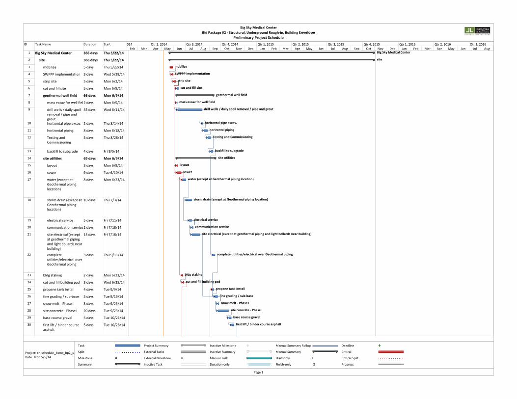
ID Task Name Duration Start
1 Big Sky Medical Center 366 days Thu 5/22/14
2 site 366 days Thu 5/22/14
3 mobilize 5 days Thu 5/22/14
4 SWPPP implementation 3 days Wed 5/28/14
5 strip site 5 days Mon 6/2/14
6 cut and fill site 5 days Mon 6/9/14
7 geothermal well field 66 days Mon 6/9/14
8 mass excav for well fiel2 days Mon 6/9/14
9 drill wells / daily spoil removal / pipe and grout
45 days Wed 6/11/14
10 horizontal pipe excav. 2 days Thu 8/14/14
11 horizontal piping 8 days Mon 8/18/14
12 Testing and Commissioning
5 days Thu 8/28/14
13 backfill to subgrade 4 days Fri 9/5/14
14 site utilities 69 days Mon 6/9/14
15 layout 3 days Mon 6/9/14
16 sewer 9 days Tue 6/10/14
17 water (except at Geothermal piping location)
8 days Mon 6/23/14
18 storm drain (except at Geothermal piping location)
10 days Thu 7/3/14
19 electrical service 5 days Fri 7/11/14
20 communication service2 days Fri 7/18/14
21 site electrical (except at geothermal piping and light bollards nearbuilding)
15 days Fri 7/18/14
22 complete utilities/electrical overGeothermal piping
3 days Thu 9/11/14
23 bldg staking 2 days Mon 6/23/14
24 cut and fill building pad 3 days Wed 6/25/14
25 propane tank install 4 days Tue 9/9/14
26 fine grading / sub‐base 5 days Tue 9/16/14
27 snow melt ‐ Phase I 3 days Tue 9/23/14
28 site concrete ‐ Phase I 20 days Tue 9/23/14
29 base course gravel 5 days Tue 10/21/14
30 first lift / binder course asphalt
5 days Tue 10/28/14
Big Sky Medical Center
site
mobilize
SWPPP implementation
strip site
cut and fill site
geothermal well field
mass excav for well field
drill wells / daily spoil removal / pipe and grout
horizontal pipe excav.
horizontal piping
Testing and Commissioning
backfill to subgrade
site utilities
layout
sewer
water (except at Geothermal piping location)
storm drain (except at Geothermal piping location)
electrical service
communication service
site electrical (except at geothermal piping and light bollards near building)
complete utilities/electrical over Geothermal piping
bldg staking
cut and fill building pad
propane tank install
fine grading / sub‐base
snow melt ‐ Phase I
site concrete ‐ Phase I
base course gravel
first lift / binder course asphalt
Feb Mar Apr May Jun Jul Aug Sep Oct Nov Dec Jan Feb Mar Apr May Jun Jul Aug Sep Oct Nov Dec Jan Feb Mar Apr May Jun Jul Aug014 Qtr 2, 2014 Qtr 3, 2014 Qtr 4, 2014 Qtr 1, 2015 Qtr 2, 2015 Qtr 3, 2015 Qtr 4, 2015 Qtr 1, 2016 Qtr 2, 2016 Qtr 3, 2016
Task
Split
Milestone
Summary
Project Summary
External Tasks
External Milestone
Inactive Task
Inactive Milestone
Inactive Summary
Manual Task
Duration‐only
Manual Summary Rollup
Manual Summary
Start‐only
Finish‐only
Deadline
Critical
Critical Split
Progress
Big Sky Medical CenterBid Package #2 ‐ Structural, Underground Rough‐in, Building Envelope
Preliminary Project Schedule
Page 1
Project: cn‐schedule_bsmc_bp2_sDate: Mon 5/5/14

ID Task Name Duration Start
31 remaining site elect at bollards / misc. near building
8 days Wed 8/5/15
32 snow melt ‐ Phase II 3 days Mon 8/17/15
33 site concrete Phase II 10 days Thu 8/20/15
34 landscaping 25 days Thu 9/3/15
35 2nd lift asphalt 5 days Fri 10/16/15
36 striping / site signs 5 days Fri 10/23/15
37 building shell 191 days Mon 6/30/14
38 Building Excavation 4 days Mon 6/30/14
39 Footings/Foundation 10 days Mon 7/7/14
40 Partial Backfill 2 days Mon 7/21/14
41 Perimeter Grade Beams 4 days Wed 7/23/14
42 Backfill balance of perime2 days Tue 7/29/14
43 Excavate interior pads/grade beams
1 day Thu 7/31/14
44 interior pads 4 days Fri 8/1/14
45 Erect steel moment frame5 days Thu 8/7/14
46 backfill interior pads/grade beams
2 days Thu 8/14/14
47 under slab plumbing 20 days Mon 8/18/14
48 under slab electrical 12 days Tue 9/2/14
49 slab prep 12 days Thu 9/4/14
50 slab on grade 9 days Wed 9/10/14
51 erect structural steel 25 days Tue 9/23/14
52 composite and roof deck 10 days Wed 10/15/14
53 elevated slabs 6 days Wed 10/29/14
54 exterior wall framing (prefab prior)
20 days Thu 11/6/14
55 roofing blocking 10 days Fri 11/28/14
56 windows 15 days Fri 11/28/14
57 curtain wall system 30 days Fri 11/28/14
58 roofing dry in 12 days Fri 12/5/14
59 masonry 35 days Fri 12/5/14
60 siding and metal panels 45 days Fri 12/12/14
61 roofing detail 12 days Tue 12/23/14
62 composite panels 30 days Tue 2/17/15
63 building interior 220 days Tue 12/23/14
64 project completion 0 days Tue 11/3/15
remaining site elect at bollards / misc. near building
snow melt ‐ Phase II
site concrete Phase II
landscaping
2nd lift asphalt
striping / site signs
building shell
Building Excavation
Footings/Foundation
Partial Backfill
Perimeter Grade Beams
Backfill balance of perimeter
Excavate interior pads/grade beams
interior pads
Erect steel moment frames
backfill interior pads/grade beams
under slab plumbing
under slab electrical
slab prep
slab on grade
erect structural steel
composite and roof deck
elevated slabs
exterior wall framing (prefab prior)
roofing blocking
windows
curtain wall system
roofing dry in
masonry
siding and metal panels
roofing detail
composite panels
building interior
project completion
Feb Mar Apr May Jun Jul Aug Sep Oct Nov Dec Jan Feb Mar Apr May Jun Jul Aug Sep Oct Nov Dec Jan Feb Mar Apr May Jun Jul Aug014 Qtr 2, 2014 Qtr 3, 2014 Qtr 4, 2014 Qtr 1, 2015 Qtr 2, 2015 Qtr 3, 2015 Qtr 4, 2015 Qtr 1, 2016 Qtr 2, 2016 Qtr 3, 2016
Task
Split
Milestone
Summary
Project Summary
External Tasks
External Milestone
Inactive Task
Inactive Milestone
Inactive Summary
Manual Task
Duration‐only
Manual Summary Rollup
Manual Summary
Start‐only
Finish‐only
Deadline
Critical
Critical Split
Progress
Big Sky Medical CenterBid Package #2 ‐ Structural, Underground Rough‐in, Building Envelope
Preliminary Project Schedule
Page 2
Project: cn‐schedule_bsmc_bp2_sDate: Mon 5/5/14

SUBCONTRACT AGREEMENT
Project: Big Sky Medical Center
Subcontractor:
Purchase Order #: 13478
THIS SUBCONTRACT AGREEMENT is effective as of March 13, 2014, between Contractor and Subcontractor. The parties agree as follows:
(406) 585-3420
Contractor: Langlas & Associates, Inc.1019 East Main StreetSuite 101Bozeman, MT 59715
Big Sky, MT
1. Subcontractor shall furnishall necessary labor, materials, tools, equipment (including safety equipment) and coordination with other trades required for completion of the following Work
A complete job of all work as required by the Project Plans and Specifications prepared by HGA Architects & Engineers, dated 1/22/14.
in the construction of the above-named Project in accordance with the terms and provisions of the contract documents, including the invitation to bidders, the instructions to bidders, the proposal, the contract, all plans, specifications, the general conditions, the special conditions, the bond, addenda.
2. Scope of Work.Whether or not enumerated in the plans or specifications, the Work includes:
(a) Any item of labor, services and material described in or reasonably inferred from the plans and specifications or customarily furnished as a part of performing work of the type required by this Subcontract, or to make the work comply with any law, ordinance or regulation, including but not limited to all scaffolding and equipment necessary or required for the performance of the Work, and all items and/or quantities that may be required by the actual conditions of the site.
(b) All plans, drawings, permits and fees required by law, regulations, ordinances or building codes.
Subcontractor shall provide, at its own expense, all ventilation, storage space, test samples, models, guarantees, permits, licenses, unloading facilities and services, temporary utilities, protection of adjacent work that has been installed by other trades, repair or replacement of work damaged by Subcontractor, and all other items necessary for the proper performance of the Work. Subcontractor shall pay for all inspection fees, royalties, and license fees relating to the Work and shall make all necessary arrangements and agreements so as not to infringe any patents, trademarks, and copyrights.
PERFORMANCE AND PAYMENT BONDS ARE REQUIRED: Yes No
All Work shall be performed in a skillful and workmanlike manner with material, equipment, etc. being new and of the best kind and grade for the purpose intended.
3. Payment.The Contractor agrees to pay the Subcontractor, the total sum of
No Dollars And No Cents (),
for actual work performed to the satisfaction of Contractor, subject to additions and deductions by Change Order. Progress payments will be made monthly in an amount equal to the estimated value of the labor, materials, and equipment incorporated into the construction and the estimated value of the materials and equipment suitably stored at the Project site, less previous payments and less retainage; progress payments shall not become due to the Subcontractor until ten (10) days after receipt by the Contractor of his payment from the Owner for such labor, materials, and equipment. Unless Subcontractor submits its written application in a form satisfactory to Contractor at least five (5) days prior to the thirty-first (31st) day of each month, no progress payment shall be payable for such payment period. All payment applications are subject to audit by Contractor and any payment may be withheld or denied pending substantiation by audit. Any estimate by Contractor of the value of Work performed during a payment period or of the amount any deduction, offset or counterclaim relating to the Work shall be binding on Subcontractor.
Retainage in a sum equal to five percent (5%) of each progress payment shall be withheld, without interest, by Contractor until final payment. Final payment shall become payable thirty (30) days after final completion and acceptance of the Project.
Prior to each payment Subcontractor shall submit from each of its sub-Subcontractors and suppliers written lien releases. Acceptance of any progress payments by Subcontractor shall constitute a release of Contractor from any other liability, except retainage, arising or incurred during the payment period. Acceptance of final payment by Subcontractor constitutes a general release of Contractor and its surety. All payments are subject to withholding by Contractor, without interest, of any amount reasonably necessary to fully protect Contractor against any actual or potential liability or damage directly or indirectly relating to the Work or this Subcontract, or against Subcontractor's breach or threatened breach hereof. Payments may be withheld on account of (1) defective work not remedied, (2) claims filed, (3) failure of Subcontractor to make payments for labor, materials, or equipment, (4) damage to the Contractor or another
1(Version 6.00, Revised 11/21/2013)

Subcontractor, or (5) persistent failure to carry out the Work in accordance with the Contract Documents. No payment shall be construed as an acceptance of defective or incomplete Work, and Subcontractor shall remain responsible and liable for strict compliance with this Subcontract and the Prime Contract.
Subcontractor hereby waives and releases any and all claims and causes of action for payment in addition to the contract price.
4. Mutuality of Documents.Subcontractor hereby acknowledges that it has carefully reviewed and examined all documents directly or indirectly relating to this Subcontract, that any and all known ambiguities and discrepancies have previously been clarified and/or corrected, and that no conditions exist which would affect the progress, performance or price of this Subcontract. Subcontractor further acknowledges that Plumbing, Mechanical, Fire Protection, and Electrical Drawings are diagrammatical in nature and may require detailed coordination with these trades in the normal course of completing Subcontractor's work. Such coordination is included in the price of this Subcontract Agreement.
5. Laws, Regulations, Etc.The Work shall strictly comply with all federal, state, and local laws, rules, regulations, statues, ordinances and directives (hereafter designated as "Laws"), including but not limited to labor laws, laws covering safety, licensing laws and bonding laws. Subcontractor agrees to indemnify and save Contractor, and Owner harmless from and against any and all claims, loss or expense caused or occasioned directly or indirectly by its failure to fully comply with any and all such Laws.
6. Extra Work or Change Orders.Subcontractor shall, within seven (7) days after discovery of a required scope modification or receipt of a request by Contractor, submit a complete and detailed price quotation for proposed changes. No extra work, alterations or deviations from this Subcontract shall be performed or allowed without the written change orders signed by Contractor, and no obligation, express or implied, is assumed by Contractor for any work done without such written consent. Any change or adjustment in the subcontract price shall be agreed to by Contractor and Subcontractor and shall be set forth in such change order; if no such agreement can be reached, Subcontractor shall perform the extra work and Contractor will pay for such work performed and materials furnished by Subcontractor in an amount equal to the actual cost thereof plus zero percent (0%) of said cost in which event Subcontractor shall prepare daily time and material invoices which shall be submitted to Contractor on a daily basis. In no event shall Subcontractor's overhead and profit percentages exceed the maximum allowed to Contractor or Subcontractor in Contractor's agreement with Owner. Daily time and material invoices shall include any direct out-in-pocket material and labor costs, plus the percentage mark-up. Contractor and Subcontractor agree that any such extra, changed or additional work performed by Subcontractor shall be performed pursuant to and in accordance with all the terms and conditions of this Subcontract. Any extension of time needed as the result of the proposed change orders shall be requested by Subcontractor, in writing, prior to the issuance of such change order and shall be incorporated therein. Ordinary field modifications which do not substantially increase Subcontractor's cost of this Subcontract will be performed without any price or time adjustment. No change orders shall vary, abrogate, avoid or otherwise affect the terms, conditions or provisions of this Subcontract except as specifically set forth in the change order.
7. Scheduling.Time is of the essence in the performance of the work specified in this Subcontract. Subcontractor agrees to prosecute the work, at such times and in such order as the Contractor considers necessary to avoid any delay in the completion of the Project as a whole. Subcontractor shall comply with the following schedule:
As scheduled by Project Manager or Jobsite Superintendent.
If no schedule is set forth above, Subcontractor agrees to begin the work within __ calendar days after being notified in writing by the Contractor to proceed and to complete work no later than __ calendar days after notice to proceed by Contractor.
Subcontractor shall timely submit all samples, drawings and information required for approval by Contractor no more than twenty (20) days from award or as otherwise stated in this Agreement, and to place all orders for materials in ample time for delivery, and to employ sufficient men and equipment to complete the Work in ample time for Contractor to complete its work in accordance with the construction schedule.
If in the opinion of Contractor the Subcontractor falls behind in the progress schedule, Subcontractor shall take such steps as may be necessary to improve the subcontract work progress, and Contractor may require Subcontractor to increase the number of shifts and/or over-time operations, days of work, work weekends and holidays, and/or increase the equipment or tools being used, and to submit for approval such supplementary schedule or schedules as may be necessary to demonstrate the manner in which the agreed rate of progress will be regained, all without additional cost to Contractor. If Subcontractor should delay or threaten to delay the progress or performance of this Subcontract, or cause any delay or actual or potential damage or liability to Contractor, then Subcontractor may be deemed in breach of this Subcontract and shall indemnify and hold Contractor harmless from any penalties, liability and/or damages, and shall promptly pay to Contractor any such costs, penalties, liabilities or damages so incurred, including attorney fees.
Subcontractor shall fully cooperate and coordinate the Work with Contractor and any other contractor or subcontractor at the Project in scheduling and performance of work so as to avoid conflict or interference with the work of others. Subcontractor shall bear the costs of all damages to other subcontractors and shall be directly responsible to such other contractors or Subcontractor.
The Contractor shall not be liable to the Subcontractor for delay to the Subcontractor's work by the act, neglect or default of any person, or by reason of fire or other casualty, or on account of riots or of strikes, or other combined action of the workmen or others, or on account of any acts of God, or any other cause beyond Contractor's control, or on account of any circumstances caused or contributed to by the Subcontractor.
2(Version 6.00, Revised 11/21/2013)

In the event any other subcontractor should interfere with the Work or damage Subcontractor, Subcontractor shall neither seek nor be entitled to any compensation from Contractor, but will seek its damages directly from such other party. Subcontractor acknowledges that the contract price herein is based on the fact that Contractor is not liable to Subcontractor, absent any actual fraud or intentional and active tortious act, for any damages or costs due to delays, accelerations, nonperformance, interferences with performance, suspensions or changes in the performance or sequence of Subcontractor's work.
8. Safety.Subcontractor shall, at its own expense, conform to the basic safety policy of Contractor including Subcontractor Site SafetyRequirements and Procedures manual attached to this Agreement, comply with all specific safety requirements promulgated by any governmental authority and comply with all state and federal safety laws, including, but not limited to the Montana Safety Culture Act, the Montana Safety Act, Occupational Safety and Health Act of 1970 or its successor, and the Construction Safety Act of 1969 or its successor, as the same may be amended from time to time. In addition, Subcontractor agrees to require its employees and sub-subcontractors to abide by all other safety requirements imposed by Contractor or the project Owner. In the event of a dispute over any safety regulation, Subcontractor and its employees shall follow the instructions given by Contractor's job superintendent. If Subcontractor causes Contractor to incur any fine or penalty resulting from the failure of Subcontractor or its employees or sub-subcontractors to comply with OSHA regulations or the Construction Safety Act, Subcontractor hereby authorizes Contractor to reduce the amount due Subcontractor under this Subcontract Agreement by the amount of such fine or penalty. Subcontractor understands that fines and penalties imposed on Contractor because of Subcontractor violations of OSHA regulations may be cumulative, so that the fine imposed on Contractor for a Subcontractor violation may be substantially larger than the fine imposed on the Subcontractor. Because of the potential civil and criminal costs to Contractor, Contractor shall have the right to immediately terminate this Subcontract Agreement, without the written notice required by Section 16, Breaches, below, if Subcontractor, or its employees or Sub-subcontractors willfully violates any safety law or regulation. In the event of such termination, Contractor shall have all of the rights and remedies set forth in Section 16, Breaches, below. Subcontractor agrees to permanently and immediately remove any employee who willfully violates any safety law or regulation upon request by Contractor's job superintendent. Subcontractor hereby agrees to indemnify and save Contractor harmless from all citations, suits (whether such citation or suit be rightfully or wrongfully brought), penalties, losses, damages, costs, and expenses including reasonable attorney fees, arising in whole or in part from the failure or alleged failure of Subcontractor to fully comply with the Montana Safety Culture Act, the Montana Safety Act, Occupational Safety and Health Act of 1970 or its successor, and the Construction Safety Act of 1969 or its successor, as the same may be amended from time to time.
9. Clean-up.Subcontractor shall keep the Project free from all rubbish, debris, and any other waste materials. Upon completion of the work, Subcontractor shall perform whatever additional clean-up work is so directed by Contractor, at no additional cost.
10. Material, Tools and Equipment.Subcontractor shall be solely responsible for the receipt, delivery, unloading, storage, warehousing, protection, and insurance upon all materials, tools and equipment it is to furnish, install, or provide under this Subcontract.
11. Indemnification.Contractor shall not be liable for any loss or casualty incurred or caused by Subcontractor; Subcontractor assumes all risk of loss for all of its work regardless of whether Subcontractor had previously been paid for the same, and for all of its materials, tools and equipment.
To the fullest extent permitted by law, Subcontractor hereby agrees to defend and to hold Contractor harmless from, and indemnifies Contractor against any and all liability, costs, damages, attorney fees, and expenses from any claims or causes of action arising on or near the Project, or relating to performance of this Subcontract or the Work, including: (a) claims relating to its subcontractors, its suppliers or its employees, and (b) claims or disputes of any person or entity for damages from any cause directly or indirectly relating to any action or failure to act by Subcontractor, its representatives, its employees, its subcontractors or its suppliers, including but not limited to inaccurate surveys, failure to properly perform or interpret tests, and inspection errors, to the extent that the liability, damages, losses or costs are caused by the negligence, recklessness, or intentional misconduct of a third party or of Subcontractor or its officers, employees or agents.
The Subcontractor agrees to indemnify the contractor against and hold the contractor harmless for any and all expenses, suits, and actions (including attorney’s fees) for or on account of any injury to any person, or any death at any time resulting from such injury, or any damage to any property, which may arise (or which may be alleged to have arisen) out of or in connection with the work covered by this Subcontract to the extent such injury, death or damage may be (or may be alleged to be) attributable to the negligence, recklessness, or intentional misconduct of a third party or of Subcontractor or its officers, its employees or its agents. The Subcontractor agrees to reimburse the Contractor for all sums which the Contractor may pay or be compelled to pay in settlement of any claim hereunder, including any claim under the provisions of any worker’s compensation law or any plan for employees’ benefits which the Contractor may adopt.
Contractor may retain any and all monies due or to become due to Subcontractor, under this or any other contract, sufficient to save itself harmless and protect itself against any such liability or damage, including attorney fees.
Subcontractor acknowledges that specific consideration has been received by it for these indemnifications.
12. Insurance.Subcontractor shall maintain full and complete insurance and additional insured status on its work for a minimum of one year after final payment, until the end of the warranty period, or such other longer period as may be required by the Contract Documents, in the following amounts:
Workers Compensation: Claims for damages because of bodily injury, occupational sickness or disease or death of
3(Version 6.00, Revised 11/21/2013)

employees.Workers Compensation StatutoryEach Accident $1,000,000Disease Policy Limit $1,000,000Disease – Each Person $1,000,000
Worker’s Compensation, including occupational disease and employer’s liability insurance shall cover all Subcontractor’s employees and company owners directly engaged in the performance of this Subcontract. Montana Contractors Exemption only allowed for company owners not directly performing work at the jobsite.
Commercial General Liability: Claims for damages because of bodily injury or property damage to third parties.Insurance shall include:
Premises-OperationsProducts-Completed OperationsContractual LiabilityPersonal and Advertising InjuryNo Exclusion for Blanket Explosion, Collapse, and Underground Property DamageOperations of Independent ContractorsNo exclusion for injury to subcontractor's employeesNo exclusion for residential, habitational or multi-family workPer Project General AggregateWaiver of subrogation in favor of contractorMinimum Policy Limits:
General Aggregate $2,000,000Products/Completed Operations $2,000,000Personal & Advertising Injury $1,000,000Each Occurrence Limit $1,000,000
In respect to the Commercial General Liability insurance which Subcontractor is obligated to purchase by the foregoing provisions, Subcontractor agrees to cause, at its sole expense, General Contractor, to be named as Additional Insured's under said policy or policies of insurance for both ongoing and completed operations using ISO Forms CG 3287 and CG 3290 or equivalent.
Subcontractor's insurance policy shall be considered primary insurance without recourse to or contribution from any similar insurance carried by subcontractor.
Automobile Liability: Claims for damages because of bodily injury or death of any person, or any property damage arising out of the ownership or use of any motor vehicle.Insurance shall include:
Owned, hired, and non-owned vehiclesLimits of $1,000,000 or greaterCombined single limit for each occurrence for bodily injury and death, or property damage.
Subcontractor shall provide notice of any material change, non-renewal or cancellation of insurance within 30 days of such change or notice. Maintenance of proper insurance coverage is a material element of this agreement and failure to maintain or renewal coverage by Subcontractor or its lower tier subcontractors may be treated as a material breach of contract. However, failure to maintain required insurance does not modify or release Subcontractor from any other obligation under this contract.
Failure of Subcontractor to maintain complete insurance and to require its Subcontractors to do so may be deemed a material breach allowing Contractor to either terminate this Subcontract or to procure such insurance at Subcontractor’s sole expense; in neither case, however, shall Subcontractor’s liability be lessened. Subcontractor agrees to pay to Contractor, on demand, all losses incurred by Contractor due to failure of Subcontractor or its subcontractors to maintain complete insurance coverage.
All liability insurance shall be maintained with a company rated at least “-A” by A. M. Best Co. All certificates of insurance, with additional insured endorsements attached, must be filed and approved with Contractor prior to scheduled commencement of the Work.
13. Assignment.Subcontractor shall not assign this Subcontract or any monies due hereunder without Contractor's written consent.
14. Liens and Encumbrances.Subcontractor agrees to promptly pay all of its laborers, materials suppliers and sub-subcontractors and, in the event any of them file a lien against the project, to promptly remove the lien, by payment or bond.
15. Taxes, Charges, Etc.Subcontractor shall pay the following taxes and fees, which are included in the Contract price:
None apply.
16. Labor Relations.Subcontractor shall take all necessary action to assure harmonious labor relations at the Project and to avoid or prevent strikes or other labor disputes. All labor used throughout the work shall be of a standing or affiliation that will permit the work to be carried on
4(Version 6.00, Revised 11/21/2013)

harmoniously and without delay, and that will not cause any disturbance, interference, or delay to the progress of the Project. Subcontractor agrees to discharge any employee objected to by Contractor upon reasonable grounds.
In the prosecution of all work covered by this Subcontract, or on this Project, the Subcontractor agrees to recognize and comply with all agreements of the Contractor with local building trade councils and/or separate unions concerning labor and working conditions and otherwise, applicable to this work, insofar as these agreements do not conflict with or violate any local, state or federal laws or properly constituted orders or regulations.
The Subcontractor agrees that where his work or the Contractor's work is stopped or delayed or interfered with by strikes, slow-downs, or work interruptions resulting from the acts or failure to act of the employees of the Subcontractor or by any breach of the provisions above, then the Contractor, at his option, may terminate this Subcontract; the Contractor shall have the remedies provided for herein even though the Subcontractor's employees may be engaging in work stoppage solely as a result of a labor dispute involving the Contractor or others and not in any manner involving the Subcontractor. Whether or not this Subcontract is terminated, Subcontractor shall be liable to Contractor for all damages, costs and expenses, including attorney fees, incurred by reason of any delay, interference, injury or damages suffered as a result thereof.
17. Breaches.Occurrence of any of the following conditions may be deemed by Contractor to be a material breach of this Subcontract by Subcontractor:
(a) Subcontractor fails to comply with any one of the provisions of this Subcontract, or fails to perform in accordance with the Prime Contract.
(b) Subcontractor fails to properly prosecute and perform any part of its work in a timely manner.
(c) Subcontractor becomes involved in labor disputes, or is listed or causes Contractor to be listed by the administrator of any union trust fund or by any union as delinquent in payment of wages or fringe benefits.
(d) Subcontractor is adjudged a bankrupt, or makes a general assignment for the benefit of creditors, or a receiver is appointed to take over Subcontractor's business or assets, or Subcontractor becomes insolvent, is unable to, or fails to, pay its obligations as they mature.
In case of breach, Subcontractor and its surety company shall be liable to Contractor for any and all additional costs, expenses, attorney fees and other damages, both liquidated and unliquidated, which directly or indirectly result from Subcontractor's breach or threatened breach. Subcontractor shall also be responsible and liable for all costs and expenses, including attorney fees, and any assessment of liquidated or other damages incurred by Contractor if Contractor pursues any extra, change, addition, claim or dispute against any other party on behalf of Subcontractor or as a result of Contractor’s defending or taking part in any action or proceeding which directly or indirectly relates to acts or omissions of Subcontractor or its subcontractors or suppliers.
If Subcontractor is in breach of this Subcontract, the Contractor shall have the right to notify Subcontractor by certified mail of the breach. If the Contractor determines that Subcontractor has not remedied and cured the default or defaults in his performance within three (3) days, then the Contractor may, at its option, without releasing or waiving its rights and remedies against the Subcontractor's sureties and without prejudice to any other right it may be entitled to hereunder or by law, terminate this Subcontract and take possession of the work and all materials, tools, equipment, and appliances of the Subcontractor and finish the Subcontractor's work by whatever means, method or agency which the Contractor may, in its sole discretion, choose, or without terminating this Subcontract, take any steps the Contractor deems advisable to secure any labor, materials, equipment, and services, and shall have a lien on and may take over all of Subcontractor's equipment, tools, appliances and materials and may prosecute the work to completion. In the event that the Contractor deems any of the foregoing remedies necessary, the Subcontractor agrees that it shall not be entitled to receive any further payment until after the Project shall have been completed. Moreover, all monies expended and all of the costs, losses, damages and extra expenses, including all management, administrative and other overhead and other direct and indirectexpenses (including attorney's fees) incurred by the Contractor incident to such completion, shall be deducted from the Subcontract sum herein stated, and if such expenditures, together with said costs, losses, damages and extra expenses, exceed the unpaid balance of the Subcontract sum, the Subcontractor agrees to pay promptly to the Contractor, on demand, the full amount of such excess, including costs of collection, attorney's fees and interest thereon at the maximum legal rate of interest per annum until paid.
The Contractor's determination of the Subcontractor's default or defaults and the Contractor's decision as to the Subcontractor's failure to remedy and cure said default or defaults upon notification of their existence, made by the Contractor in good faith, shall be conclusive as to the Contractor's right to proceed as herein provided. The liability of the Subcontractor hereunder shall extend to and include the full amount of any and all sums paid, expenses and losses incurred, damages sustained, and obligations assumed by the Contractor in good faith under the belief that such payments or assumptions were necessary or required, whether actually necessary or required or not, (a) in completing the work and providing labor, materials, equipment, supplies and other items therefor or reletting the Subcontract, and (b) in settlement, discharge or compromise of any claims, demands, suits and judgments pertaining to or arising out of the work hereunder. A sworn itemized statement thereof or the checks or other evidence of payment shall be prima facie evidence of the fact and extent of Subcontractor's liability.
In addition to the cost of completion paid by Contractor, Subcontractor agrees to pay an amount equal to twenty percent (20%) of such cost of completion to cover Contractor's overhead in respect thereto. Whenever any monies are expended or costs or expenses are incurred by Contractor on behalf of or on account of Subcontractor, which Subcontractor should have paid and for which Subcontractor is required to reimburse Contractor, or if Contractor continues or completes the Work after default by Subcontractor, Subcontractor shall pay to Contractor interest at the maximum rate permitted by law from the time said monies are expended or said costs orexpenses are incurred until the same are paid to Contractor by Subcontractor. Nothing herein contained shall be construed asrequiring Contractor to make any such expenditures, advance any such monies, or incur any such expenses.
5(Version 6.00, Revised 11/21/2013)

18. Termination for Convenience.Upon seven days written notice to the Subcontractor, the Contractor may, without cause and without prejudice to any other right of Contractor, terminate the Subcontract. In such case the Subcontractor shall be paid for (without duplication of any item):
1. completed and acceptable Work executed in accordance with the Subcontract prior to the effective date of termination;
2. reasonable expenses directly attributable to termination.
The Subcontractor shall not be paid on account of loss of anticipated profits or revenue or other economic loss arising out of or resulting from the termination.
19. Notice.Any notice which Contractor desires to or is required to give to Subcontractor may be delivered to Subcontractor's representative or may be delivered or mailed to Subcontractor at the address set forth in this Subcontract. Such notice shall be deemed served upon actual delivery or upon being deposited in the United States mail so addressed, and postage thereon prepaid.
20. Subcontractors and Suppliers.At the time of commencing the Work, Subcontractor shall submit to Contractor a complete written list of all sub-subcontractors and suppliers and their current addresses. Subcontractor further agrees to notify Contractor of any additions, deletions or changes in said list within five (5) days of any such changes.
21. Guarantee.Subcontractor agrees to guarantee its work for a period of one (1) year from the date of completion of the Project. Subcontractor shall remove, replace and/or repair at its own expense defective workmanship, materials and equipment which shall fail to develop ratings, capacities or characteristics required by this Subcontract, or the Contract documents, at any time within a period of one (1) year after acceptance of the Project or within such longer period thereafter as may be provided in the Prime Contract and related documents, if due to Subcontractor's negligence or error. Subcontractor shall also pay all costs necessary to remove, replace and/or repair any other work which may be damaged in removing, replacing or repairing any portion of the Work for which Subcontractor is responsible.
Contractor may demand assurance, by bond or otherwise, from Subcontractor that it will abide by its guarantee and warranty asspecified herein and as might otherwise be specified to a greater extent in the Prime Contract.
22. Governing Law.The validity, interpretation and performance of this Subcontract shall be governed by the laws of the State of Montana. If any term or provision of this Subcontract is found invalid, it shall not affect the valid enforcement of all remaining terms and provisions of this Subcontract.
23. Contract Modifications.This Subcontract cannot be changed, modified or amended except in writing executed by all parties. This Subcontract supersedes all prior representations, understandings or agreements except as expressly stated herein. This Subcontract shall be binding upon the heirs, successors, administrators and assigns of the parties hereto.
24. Failure to Sign Agreement.In the event Subcontractor has failed to sign and return to Contractor a copy of this Subcontract after having received a copy hereof from Contractor, and the Subcontractor enters upon performance of the Work, such performance shall be deemed Subcontractor's consent and agreement to be bound by all the terms and conditions of this Subcontract.
25. Attorney Fees.In the event Contractor is required to employ an attorney or bring legal action to enforce this Subcontract or to take any action in respect thereto, or to defend any action arising out of Subcontractor's operations hereunder, Subcontractor agrees in any such event to pay Contractor's reasonable costs and attorney fees, including costs and fees on any appeal.
26. Miscellaneous.
None.
Signature:
(Stephen T. Langlas)
Title: Vice-President
CONTRACTOR SUBCONTRACTOR
Signature:
Title:
6(Version 6.00, Revised 11/21/2013)
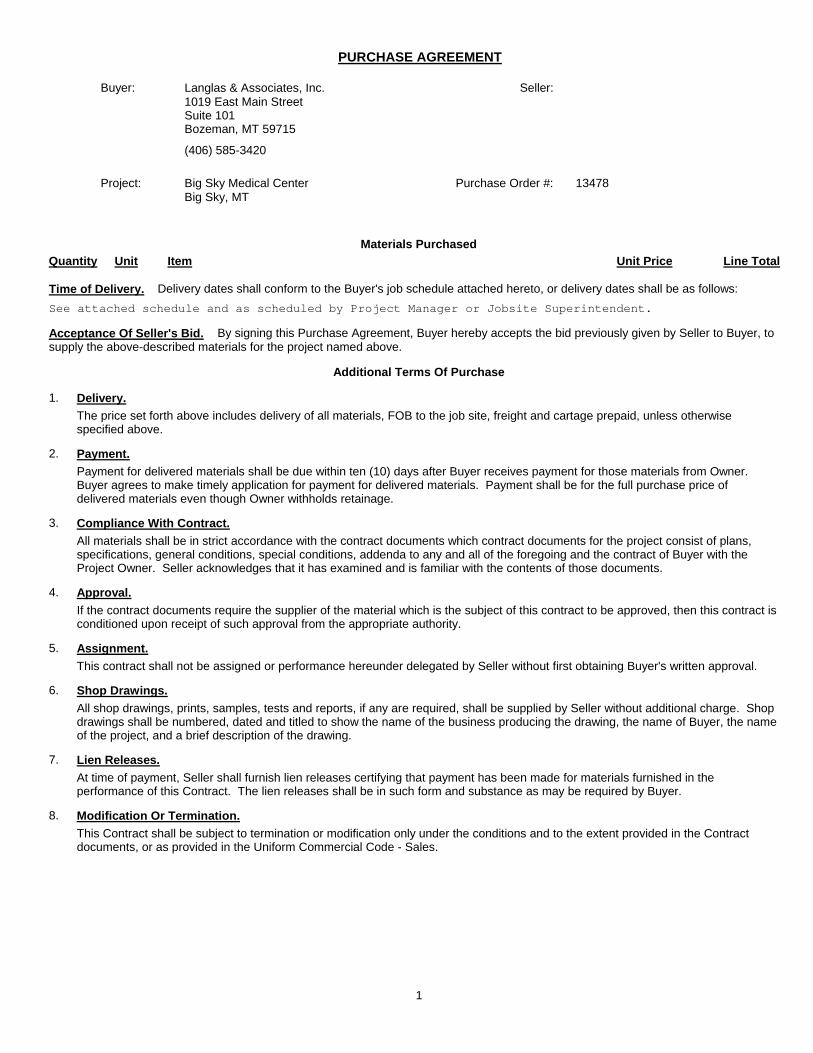
PURCHASE AGREEMENT
Project: Big Sky Medical Center
Seller:
Purchase Order #: 13478
(406) 585-3420
Buyer: Langlas & Associates, Inc.
Materials Purchased
Time of Delivery. Delivery dates shall conform to the Buyer's job schedule attached hereto, or delivery dates shall be as follows:
See attached schedule and as scheduled by Project Manager or Jobsite Superintendent.
Acceptance Of Seller's Bid. By signing this Purchase Agreement, Buyer hereby accepts the bid previously given by Seller to Buyer, to
Quantity Unit Item Unit Price Line Total
1019 East Main StreetSuite 101Bozeman, MT 59715
Big Sky, MT
supply the above-described materials for the project named above.
Additional Terms Of Purchase
1. Delivery.
The price set forth above includes delivery of all materials, FOB to the job site, freight and cartage prepaid, unless otherwise specified above.
2. Payment.
Payment for delivered materials shall be due within ten (10) days after Buyer receives payment for those materials from Owner. Buyer agrees to make timely application for payment for delivered materials. Payment shall be for the full purchase price of delivered materials even though Owner withholds retainage.
3. Compliance With Contract.
All materials shall be in strict accordance with the contract documents which contract documents for the project consist of plans, specifications, general conditions, special conditions, addenda to any and all of the foregoing and the contract of Buyer with the Project Owner. Seller acknowledges that it has examined and is familiar with the contents of those documents.
4. Approval.
If the contract documents require the supplier of the material which is the subject of this contract to be approved, then this contract is conditioned upon receipt of such approval from the appropriate authority.
5. Assignment.
This contract shall not be assigned or performance hereunder delegated by Seller without first obtaining Buyer's written approval.
6. Shop Drawings.
All shop drawings, prints, samples, tests and reports, if any are required, shall be supplied by Seller without additional charge. Shop drawings shall be numbered, dated and titled to show the name of the business producing the drawing, the name of Buyer, the name of the project, and a brief description of the drawing.
7. Lien Releases.
At time of payment, Seller shall furnish lien releases certifying that payment has been made for materials furnished in the performance of this Contract. The lien releases shall be in such form and substance as may be required by Buyer.
8. Modification Or Termination.
This Contract shall be subject to termination or modification only under the conditions and to the extent provided in the Contract documents, or as provided in the Uniform Commercial Code - Sales.
1
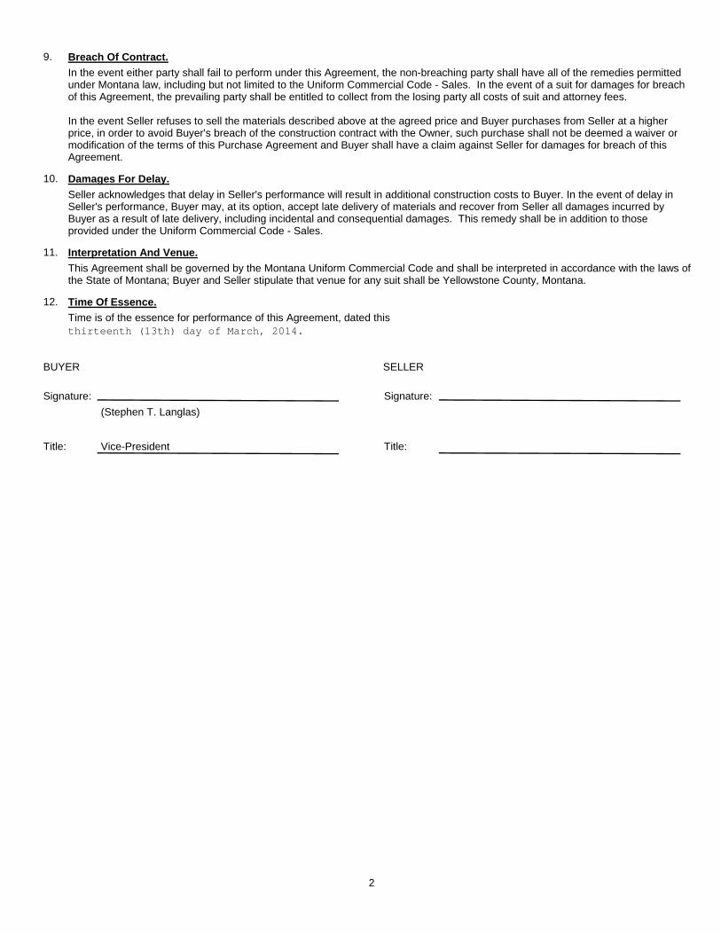
Signature:
(Stephen T. Langlas)
Title: Vice-President
BUYER SELLER
Signature:
Title:
thirteenth (13th) day of March, 2014.
9. Breach Of Contract.
In the event either party shall fail to perform under this Agreement, the non-breaching party shall have all of the remedies permitted under Montana law, including but not limited to the Uniform Commercial Code - Sales. In the event of a suit for damages for breach of this Agreement, the prevailing party shall be entitled to collect from the losing party all costs of suit and attorney fees.
In the event Seller refuses to sell the materials described above at the agreed price and Buyer purchases from Seller at a higher price, in order to avoid Buyer's breach of the construction contract with the Owner, such purchase shall not be deemed a waiver or modification of the terms of this Purchase Agreement and Buyer shall have a claim against Seller for damages for breach of this Agreement.
10. Damages For Delay.
Seller acknowledges that delay in Seller's performance will result in additional construction costs to Buyer. In the event of delay in Seller's performance, Buyer may, at its option, accept late delivery of materials and recover from Seller all damages incurred by Buyer as a result of late delivery, including incidental and consequential damages. This remedy shall be in addition to those provided under the Uniform Commercial Code - Sales.
11. Interpretation And Venue.
This Agreement shall be governed by the Montana Uniform Commercial Code and shall be interpreted in accordance with the laws of the State of Montana; Buyer and Seller stipulate that venue for any suit shall be Yellowstone County, Montana.
12. Time Of Essence.
Time is of the essence for performance of this Agreement, dated this
2

BIG SKY MEDICAL CENTER BOZEMAN DEACONESS HEALTH SERVICES BID PACKAGE 1 BIG SKY, MONTANA BID SET
Bid Package No. 1- Site Work, Utilities, Building Excavation, Slab Preperation, Sit e Electrical, Geothermal Wells
GENERAL WARRANTY / GUARANTEE for
Big Sky Medical Center Bid Package No. 1 Big Sky, MT 59937
Contractor: Representative: Telephone: ____________________{Contractor} shall and hereby does warrant and guarantee to Bozeman Deaconess Health Services that all material, equipment and workmanship which has become part of the complete project is free of defects and shall remain in working order for a period of not less than one (1) year from the date of ___________{Substantial Completion}. ____________________{Contractor} hereby assumes during the guarantee period the responsibility of repairing all defective material, equipment and workmanship without charge to the Owner. Nothing in the above intends or implies that this guarantee shall apply to any defects in material, equipment or workmanship which has resulted from misuse, abuse or neglect by the Owner or Owner’s agent. By: Title: The foregoing was subscribed and sworn to before me This day of , 2013. By (as of ). My Commission Expires: SEAL Notary Public STATE OF COUNTY OF

Date Issued:
To: HGA Architects & Engineers RFI Submitted by:202 1st Avenue SWRochester, Minnesota 55902 Subject:
Attn: Kim JensenTel: 507-281-8600 Fax: 507-281-8688
Information Requested:
Potential Cost Impact Potential Schedule Impact Date Requested By:
Response:
Signed By: Date Answered:
RFI Direction Notice:Proceed with work as noted above.Do not proceed with work. Please provide pricing for work as described above.
Distribution/Affected Trades:
1/7/1900
___________________________________________________________________________________________________________________________
Big Sky Medical Center
Request For InformationRFI #
2270 Grant Road Billings, MT 59102 Ph: 404-656-0629 Fax: 406-656-10881019 E. Main St. Ste. #101 Bozeman, MT 59715 Ph: 406-585-3420 Fax: 406-585-3420

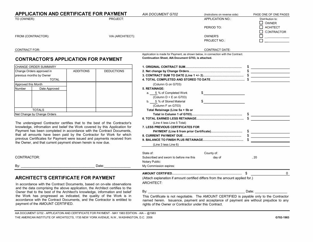
APPLICATION AND CERTIFICATE FOR PAYMENT AIA DOCUMENT G702 (Instrutions on reverse side) PAGE ONE OF ONE PAGES
TO (OWNER): PROJECT: APPLICATION NO.: Distribution to:
OWNER
PERIOD TO: ACHITECT
CONTRACTOR
FROM (CONTRACTOR): VIA (ARCHITECT): OWNER'S _____________
PROJECT NO.: _____________
CONTRACT FOR: CONTRACT DATE:
Application is made for Payment, as shown below, in connection with the Contract.
CONTRACTOR'S APPLICATION FOR PAYMENT Continuation Sheet, AIA Document G703, is attached.
CHANGE ORDER SUMMARY 1. ORIGINAL CONTRACT SUM&&&&&&&&&&&&&&&&&&.. $
Change Orders approved in ADDITIONS DEDUCTIONS 2. Net change by Change Orders&&&&&&&&&&&&&&&&& $
previous months by Owner 3. CONTRACT SUM TO DATE (Line 1 +/- 2)&&&&&&&&&&&&&. $TOTAL 4. TOTAL COMPLETED AND STORED TO DATE&&&&&&&&&&&. $
Approved this Month (Column G on G703)
Number Date Approved 5. RETAINAGE:
a. 5 % of Completed Work $
(Column D + E on G703)
b. 5 % of Stored Material $
(Column F on G703)
TOTALS Total Retainage (Line 5a + 5b or
Net Change by Change Orders Total in Column 1 of G703)&&&&&&&&&&&&&&&&.. $
6. TOTAL EARNED LESS RETAINAGE&&&&&&&&&&&&&&&.. $
(Line 4 less Line 5 Total)
7. LESS PREVIOUS CERTIFICATES FOR
PAYMENT (Line 6 from prior Certificate)&&&&&&&&&&. $
8. CURRENT PAYMENT DUE&&&&&&&&&&&&&&&&&&&. $9. BALANCE TO FINISH PLUS RETAINAGE&&&&&&&&&&&&&. $
(Line 3 less Line 6)
State of: County of:
CONTRACTOR: Subscribed and sworn to before me this day of , 20
Notary Public:
By: _______________________________________ Date:______________ My Commission expires:
AMOUNT CERTIFIED&&&&&&&&&&&&&&&&&&&&&&& $ 0
ARCHITECT'S CERTIFICATE FOR PAYMENT (Attach explanation if amount certified differs from the amount applied for.)
ARCHITECT:
By: ___________________________________________________ Date: _________________
AIA DOCUMENT G702 - APPLICATOIN AND CERTIFICATE FOR PAYMENT - MAY 1983 EDITION - AIA -- @1983
THE AMERICAN INSTITUTE OF ARCHITECTS, 1735 NEW YORK AVENUE, N.W., WASHINGTON, D.C. 2006 G702-1983
The undersigned Contractor certifies that to the best of the Contractor'sknowledge, infromation and belief the Work covered by this Application forPayment has been completed in accordance with the Contract Documents,that all amounts have been paid by the Contractor for Work for whichprevious Certificates for Payment were issued and payments received fromthe Owner, and that current payment shown herein is now due.
In accordance with the Contract Documents, based on on-site observationsand the data comprising the above application, the Architect certifies to theOwner that to the best of the Architect's knowledge, information and beliefthe Work has progressed as indicated, the quality of the Work is inaccordance with the Contract Documents, and the Contractor is entitled topayment of the AMOUNT CERTIFIED.
This Certificate is not negotiable. The AMOUNT CERTIFIED is payable only to the Contractornamed herein. Issuance, payment and acceptance of payment are without prejudice to anyrights of the Owner or Contractor under this Contract.

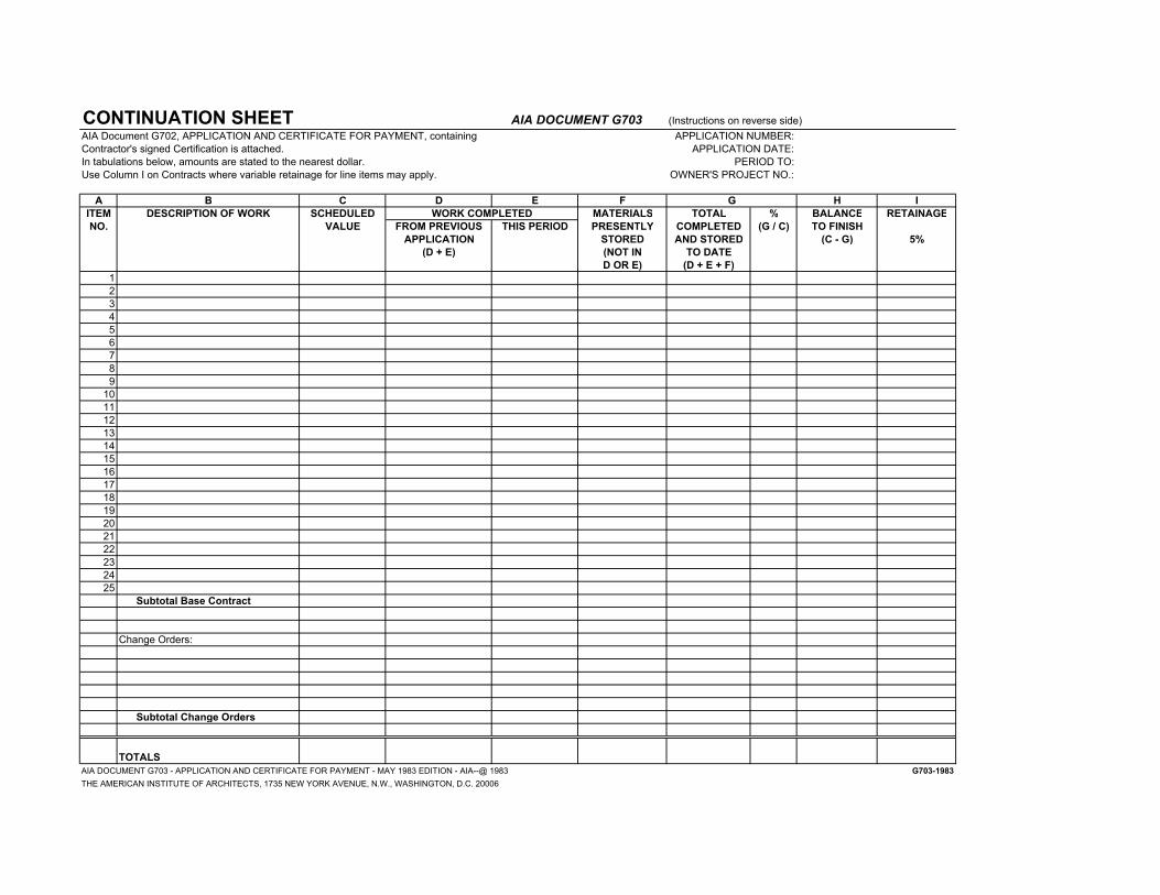
CONTINUATION SHEET AIA DOCUMENT G703 (Instructions on reverse side)
AIA Document G702, APPLICATION AND CERTIFICATE FOR PAYMENT, containing APPLICATION NUMBER:
Contractor's signed Certification is attached. APPLICATION DATE:
In tabulations below, amounts are stated to the nearest dollar. PERIOD TO:
Use Column I on Contracts where variable retainage for line items may apply. OWNER'S PROJECT NO.:
A B C D E F G H I
ITEM DESCRIPTION OF WORK SCHEDULED WORK COMPLETED MATERIALS TOTAL % BALANCE RETAINAGE
NO. VALUE FROM PREVIOUS THIS PERIOD PRESENTLY COMPLETED (G / C) TO FINISH
APPLICATION STORED AND STORED (C - G) 5%
(D + E) (NOT IN TO DATE
D OR E) (D + E + F)
1
2
3
4
5
6
7
8
9
10
11
12
13
14
15
16
17
18
19
20
21
22
23
24
25
Subtotal Base Contract
Change Orders:
Subtotal Change Orders
TOTALS
AIA DOCUMENT G703 - APPLICATION AND CERTIFICATE FOR PAYMENT - MAY 1983 EDITION - AIA--@ 1983 G703-1983
THE AMERICAN INSTITUTE OF ARCHITECTS, 1735 NEW YORK AVENUE, N.W., WASHINGTON, D.C. 20006

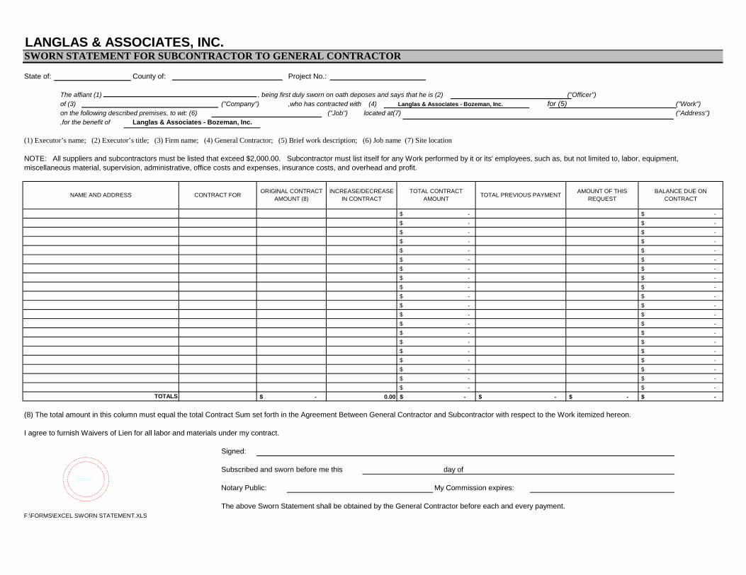
LANGLAS & ASSOCIATES, INC.SWORN STATEMENT FOR SUBCONTRACTOR TO GENERAL CONTRACTOR
State of: County of: Project No.:
The affiant (1) , being first duly sworn on oath deposes and says that he is (2) ("Officer")of (3) ("Company") ,who has contracted with (4) Langlas & Associates - Bozeman, Inc. for (5) ("Work")on the following described premises, to wit: (6) ("Job") located at(7) ("Address"),for the benefit of Langlas & Associates - Bozeman, Inc.
(1) Executor’s name; (2) Executor’s title; (3) Firm name; (4) General Contractor; (5) Brief work description; (6) Job name (7) Site location
NOTE: All suppliers and subcontractors must be listed that exceed $2,000.00. Subcontractor must list itself for any Work performed by it or its' employees, such as, but not limited to, labor, equipment, miscellaneous material, supervision, administrative, office costs and expenses, insurance costs, and overhead and profit.
(8) The total amount in this column must equal the total Contract Sum set forth in the Agreement Between General Contractor and Subcontractor with respect to the Work itemized hereon.
I agree to furnish Waivers of Lien for all labor and materials under my contract.
Signed:
Subscribed and sworn before me this day of SEAL
Notary Public: My Commission expires:
The above Sworn Statement shall be obtained by the General Contractor before each and every payment.F:\FORMS\EXCEL SWORN STATEMENT.XLS
-$ -$
$ -
$ -
-$ -$ 0.00TOTALS
$ -
$ -
$ -
$ -
$ -
$ -
$ -
$ -
$ -
$ -
$ -
$ -
$ -
$ -
$ -
$ -
$ -
$ -
$ -
$ -
$ -
$ -
$ -
$ -
$ -
$ -
$ -
$ -
$ -
$ -
$ -
$ -
BALANCE DUE ON CONTRACT
AMOUNT OF THIS REQUEST
$ -
INCREASE/DECREASE IN CONTRACT
TOTAL CONTRACT AMOUNT
TOTAL PREVIOUS PAYMENT
$ -
$ -
$ -
NAME AND ADDRESS CONTRACT FORORIGINAL CONTRACT
AMOUNT (8)
$ -
$ -
$ -


INTERIM LIEN / CLAIM WAIVER
Name of Firm:
Project:
PLEASE SIGN AND MAIL OR FAX:
LANGLAS & ASSOCIATES - BOZEMAN 1019 EAST MAIN STREET – SUITE 101
BOZEMAN MT 59715 FAX: 406-585-4110
CONDITIONAL RELEASE
The undersigned does hereby acknowledge that upon receipt by the undersigned of a check from {name of firm/individual writing check}:
_________________________________ in the sum of $_____________________ and when the check has been properly endorsed and has been paid by the bank upon which it was drawn, this document shall become effective to release any and all claims and
rights of lien which the undersigned has on the above referenced job. In addition, the undersigned warrants that all subcontractors and employees and all expenses for materials and leased equipment or machinery have been fully paid. This release covers a progress payment for labor, services, equipment,
materials furnished, and/or claims through {date} ______________ only and does not cover any retention or items furnished after that date. Before any recipient of this document relies on it, said party should verify evidence of payment to the undersigned.
I certify under penalty of perjury under laws of the
State of Montana that the above is a true and
correct statement.
Signature: ________________________________________ {Authorized Corporate Officer/Partner/Owner} Title: ___________________________________
Date: _______________________________
UNCONDITIONAL RELEASE
The undersigned does hereby acknowledge that the undersigned has been paid and has received progress payments in the sum of $_______________ for labor, services, equipment or materials furnished to the above referenced job and does hereby release any and all claims and rights of lien which the undersigned has on
the above referenced job. In addition, the undersigned warrants that all subcontractors and employees and all expenses for materials and leased equipment or machinery have been fully paid. This release covers all payment for labor, services, equipment, materials furnished, and/or claims to the above referenced job
through {date} _____________ only and does not cover any retention or items furnished after that date. NOTICE: This document waives rights unconditionally
and states that you have been paid for giving up those
rights. This document is enforceable against you if you
sign it, even if you have not been paid. If you have not
been paid, use a Conditional Release.
I certify under penalty of perjury under laws of the State
of Montana that the above is a true and correct
statement.
Signature:
________________________________________ {Authorized Corporate Officer/Partner/Owner} Title: ___________________________________ Date: _______________________________

Page 1 of 14 Subcontractor Site Safety Requirements and Procedures January 2012
www.langlas.com 2270 Grant Road 1019 E. Main St. Suite 101 Billings, Montana 59102 Bozeman, Montana 59715 Phone (406) 656‐0629 Phone (406) 585‐3420 Fax (406) 656‐1088 Fax (406) 585‐4110
Subcontractor Site Safety Requirements
Page 2 of 14 Subcontractor Site Safety Requirements and Procedures January 2012
SUBCONTRACTOR SITE SAFETY REQUIREMENTS AND PROCEDURES
INTRODUCTION The enclosed information addresses expectations of employees, Subcontractors and Tier Subcontractors [herein after called subcontractors] performing work on Langlas projects. Through the concentrated effort of subcontractors, a safe and successful project can be achieved.
Each subcontractor working on Langlas projects is obligated to comply with all Federal, State and Local safety requirements, the Langlas & Associates Safe Procedures Manual, Site Specific Safety Programs, and any Owner Safety Requirements [herein after called safety requirements]. These combined safety requirements constitute the minimum level of performance expected from each subcontractor and their employees or their tiered subcontractors, or agents. All subcontractors shall adhere to these requirements for the performance of their work on Langlas projects.
SUBCONTRACTOR COMPLIANCE In accordance with the OSHA requirements, each subcontractor shall protect the employment and places of employment of each of his employees engaged in construction work by complying with the appropriate standards prescribed in the applicable standards. Subcontractors shall hold each of their agents, vendors, tier subcontractors and suppliers responsible for compliance with these safety requirements. Subcontractors shall include these safety requirements in contracts with all tier subcontractors and suppliers. Entry onto project, property, or the job site constitutes acknowledgement by the subcontractor, subcontractor employees or invitee of their obligation to adhere to these safety requirements.
Each subcontractor shall establish and maintain an effective safety and health program in accordance with OSHA’s Construction Standard (29 CFR 1926), any other applicable standards required by law, and all items outlined in this document. The subcontractor shall be solely responsible for implementing their safety program and shall have sole responsibility for monitoring the work of its employees, subcontractors, agents, vendors and suppliers to ensure compliance.
VIOLATIONS If a subcontractor or invitee is found to be non‐compliant with any of the safety requirements, that subcontractor will be solely responsible for correcting the non‐compliant item. Any resulting damages (including damage for delay) will be paid for in accordance with the subcontract. Langlas will exercise oversight of the safety performance of subcontractors while working on a Langlas project. When violations of the safety requirements are observed, the responsible contractor shall be informed verbally for immediate correction. It is the sole responsibility of the subcontractor to devise and implement the correction.
Page 3 of 14 Subcontractor Site Safety Requirements and Procedures January 2012
If Langlas deems it is necessary to stop work being performed due to the nature of a violation, work will be halted until the subcontractor corrects the violations. Any costs incurred by the stoppage of work due to the Safety and Health violation will be the sole responsibility of the violating subcontractor. The subcontractor shall be given a reasonable amount of time to correct the violation(s). The time period allowed shall reflect the severity of the violation(s) and the urgency to abate, and in some cases the corrective action might be immediate. If the subcontractor fails to correct the violation within the Reasonable amount of time specified, Langlas may take a number of actions including but not limited to: A meeting conducted with the subcontractor’s supervisor and the Langlas Project Team. The
meeting would conclude in a documented agreement outlining the subcontractor’s intended corrective actions and timeframe for implementation.
Removal of unsafe condition by using other work forces, the cost of which would be reimbursed by the violating subcontractor through the provisions of the contract.
Removal of subcontractor personnel, including field supervision if necessary. A letter of non‐compliance stating that the subcontractor is in violation may be sent to the
subcontractor’s office with a copy to their insurance company. Langlas may exercise its option to terminate all or part of the contract with the subcontractor
for inadequate safety performance or failure to fulfill any of the safety requirements of the contract.
THE FOLLOWING VIOLATIONS WILL BE GROUNDS FOR IMMEDIATE DISCHARGE OF SUBCONTRACTOR PERSONNEL: Gross negligence of safety and health rules and regulations, repeated violations or the refusal to
follow safety and health rules and regulations. Fighting (physical contact), horseplay, or sleeping on the job. Theft. Drugs or alcohol (possession or under the influence). Willful destruction of property. Possession of firearms or explosive devices. Engaging in any inappropriate, unwanted verbal or physical advances to the public or co‐
workers, or any violation of the Langlas & Associates sexual harassment policy.
DESIGNATION OF COMPETENT PERSON Each subcontractor shall designate a competent person as defined by OSHA to implement and enforce the safety requirements. A competent person from each subcontractor must be on site whenever they have employees working on site, and the name of that person shall be submitted to the Langlas Site Supervisor on the Daily Sign‐in Sheet available in the jobsite trailer at each jobsite. Each subcontractor is required to maintain this position, with the competent person(s) remaining on‐site until the completion of their work. The subcontractor shall not relinquish or defer responsibility for project safety to his own or subcontractor employees at any time under any circumstances.

Page 4 of 14 Subcontractor Site Safety Requirements and Procedures January 2012
OSHA AND STATE AGENCY INSPECTIONS If after an inspection, a subcontractor receives any citation(s), a copy of all citations shall be immediately given to Langlas.
ATTENDANCE OF MEETINGS Preconstruction Meeting Langlas may require the attendance of both the Project Manager and Jobsite Foreman at a Preconstruction Meeting with the Langlas & Associates project team. The purpose of this meeting is to review expectations, schedule, coordination, quality, safety and other concerns. Foreman’s Meeting Foreman’s meetings will be conducted on site. The date and time of these meetings will be determined by the project team on an as needed basis. Attendance is expected from each subcontractor unless excused by Langlas. Incident Review Following an incident, Langlas may request a meeting be held with the parties involved to discuss the incident in more detail. Requested subcontractors shall attend and participate in the investigation, discussion, and to develop an action plan.
EMERGENCY MEDICAL FACILITY Each subcontractor is responsible to establish an Emergency Medical Facility for use by injured employees. The facility to be used shall be communicated to subcontractor employees by the subcontractor. The subcontractor is responsible for all costs borne out of medical treatment, substance abuse testing and any other associated costs (Langlas is not to be charged for any treatment costs). Each subcontractor is to provide an appropriate sized First Aid kit that is maintained and adequately stocked. The location of the kit shall be shared with the crew.
DOCUMENTATION AND REPORTING
PROGRAM SUBMITTAL MSDS & Hazard Communication Program Each subcontractor and tier subcontractor shall submit a copy of their Hazard Communication Program and Material Safety Data Sheets [applicable to the site] to the Project Team. Each subcontractor shall notify their employees of the location of the Hazard Communication Program and MSDS. Langlas shall be notified when Hazardous Materials will be used and what protective methods will be used to protect those employees directly involved and those employees who may become exposed. The
Page 5 of 14 Subcontractor Site Safety Requirements and Procedures January 2012
competent person for the subcontractor involved will be responsible for monitoring use and compliance by its employees with the protective methods devised. Safety Plan In accordance with OSHA, each subcontractor shall create a project specific Safety Plan prior to the start of their work.
SITE ORIENTATION Each subcontractor employee, before starting work, is to be trained by the subcontractor on the safety requirements established for the project.
TOOLBOX TALKS Each subcontractor shall conduct weekly “toolbox” safety meetings relevant to the work being performed for their employees. A copy of the “toolbox talk” or a description of the topic discussed along with all attendees names shall be kept on site at all times.
SAFETY INSPECTIONS In accordance with OSHA, each subcontractor shall perform frequent and regular safety inspections of their work area(s) by a competent person. A copy of the report or documented inspection shall be submitted Langlas whenever the inspection is completed. Subcontractor supervisors shall take immediate action to correct violations, unsafe practices and unsafe conditions. The subcontractor will be solely responsible to review/monitor the work area/location of all their employees on a regular basis during the performance of work.
SUBSTANCE ABUSE POLICY Langlas is committed to providing a safe work environment. The illegal use or abuse of drugs and or alcohol constitutes a threat to the safety and health of employees and the general public. The Substance Abuse Policy requires employees to report to work fit for duty, and to perform their work, free of detectable levels of drugs, alcohol, or other substances which may affect their ability to work safely. Each subcontractor shall establish and maintain an effective substance abuse program that at the least equals that of the Langlas & Associates Substance Abuse Program. Drug and alcohol testing is required of subcontractor employees in the following situations: If Langlas has reasonable suspicion that the employee is under the influence of drugs or alcohol
[immediate testing required]. If the employee has sustained a work‐related injury requiring outside medical attention
[immediate testing required]. If the employee has caused or contributed to another employee being injured in a work‐related
incident [immediate testing required]. If the employee has caused or contributed to a work‐related incident resulting in, or which has
the potential to result in, property damage [immediate testing required].
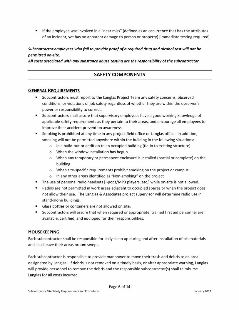
Page 6 of 14 Subcontractor Site Safety Requirements and Procedures January 2012
If the employee was involved in a “near miss” (defined as an occurrence that has the attributes of an incident, yet has no apparent damage to person or property) [immediate testing required].
Subcontractor employees who fail to provide proof of a required drug and alcohol test will not be
permitted on‐site.
All costs associated with any substance abuse testing are the responsibility of the subcontractor.
SAFETY COMPONENTS
GENERAL REQUIREMENTS Subcontractors must report to the Langlas Project Team any safety concerns, observed
conditions, or violations of job safety regardless of whether they are within the observer’s power or responsibility to correct.
Subcontractors shall assure that supervisory employees have a good working knowledge of applicable safety requirements as they pertain to their areas, and encourage all employees to improve their accident prevention awareness.
Smoking is prohibited at any time in any project field office or Langlas office. In addition, smoking will not be permitted anywhere within the building in the following situations:
o In a build‐out or addition to an occupied building (tie‐in to existing structure) o When the window installation has begun o When any temporary or permanent enclosure is installed (partial or complete) on the
building o When site‐specific requirements prohibit smoking on the project or campus o In any other areas identified as “Non‐smoking” on the project
The use of personal radio headsets [I‐pods/MP3 players, etc.] while on‐site is not allowed. Radios are not permitted in work areas adjacent to occupied spaces or when the project does
not allow their use. The Langlas & Associates project supervisor will determine radio use in stand‐alone buildings.
Glass bottles or containers are not allowed on site. Subcontractors will assure that when required or appropriate, trained first aid personnel are
available, certified, and equipped for their responsibilities.
HOUSEKEEPING Each subcontractor shall be responsible for daily clean up during and after installation of his materials and shall leave their areas broom swept. Each subcontractor is responsible to provide manpower to move their trash and debris to an area designated by Langlas. If debris is not removed on a timely basis, or after appropriate warning, Langlas will provide personnel to remove the debris and the responsible subcontractor(s) shall reimburse Langlas for all costs incurred.

Page 7 of 14 Subcontractor Site Safety Requirements and Procedures January 2012
PERSONAL PROTECTIVE EQUIPMENT Hard Hats Hard hats are to be worn 100% of the time, through all phases of construction.
Hard hats shall be worn correctly. Equipment operators and delivery drivers working outside of the equipment are required to wear hard hats 100% of the time.
Hair Hair which falls below the nape of the neck must be put under the hard hat, in a
hair net, put in a ponytail, or otherwise controlled. Clothing Long pants and a shirt are to be worn. High visibility vests are to be worn when
working in and around motorized equipment. No shorts, tank tops, or any inappropriate articles of clothing can be worn. If someone is wearing anything
that Langlas finds inappropriate, they will ask the individual to remove/cover the
article. If they cannot or refuse to do so, they will be removed from the site.
Footwear Substantial leather footwear will be worn, preferably full height work boots.
“Gym Shoe” style work shoes are not permitted. Fall Protection Equipment must meet and be maintained in accordance with OSHA Subpart M. Hearing Protection Hearing protection will be required in accordance with OSHA standards. Eye/Face Protection Eye and face protection when required, [i.e. overhead drilling or cutting,
chipping, welding, burning, grinding, or mixing or working with cleaners] must meet applicable ANSI requirements.
Respirators If respirators are required, the contractor must be in compliance with all
applicable OSHA standards. When the use of respirators is required, proof of appropriate fit testing and training will be submitted by each subcontractor, upon request by Langlas & Associates.
Each subcontractor is solely responsible to supply their employees with Personal Protective Equipment.
LADDERS AND STAIRWAYS No portable metal ladders. Damaged ladders must be removed from service. All ladders are to be used correctly. Job‐made ladders must meet ANSI standards. A ladder or stairway is required at a point of access where there is a change in elevation greater
than 19”.

Page 8 of 14 Subcontractor Site Safety Requirements and Procedures January 2012
Extension ladders must set at a 4:1 slope, be secured, and extend 3’ above the landing or have a grab bar provided.
Each subcontractor shall provide ladder training for all employees using ladders. Stairs and platforms must be used to provide access to office, equipment and material storage. Stairways must be kept free of flammable materials, stored materials or debris.
SCAFFOLDS All scaffolds shall be erected, used, and dismantled in accordance with OSHA’s Subpart L and Local Codes, if applicable. Key elements include: Scaffolds shall be inspected prior to each day’s use and whenever altered or repaired.
Documentation of inspections shall be kept by the subcontractor. Employees using, erecting or dismantling scaffolds shall be appropriately trained. The working level of a scaffold shall be fully decked or additional fall protection is required. Fall protection is required when erecting, moving, or dismantling scaffolds that are higher than
10’. If the subcontractor deems that fall protection is not feasible or world pose a greater hazard, they shall submit their justification in writing to Langlas (for recordkeeping purposes).
Hallway/Narrow Frame Mobile (Baker) scaffolds with a working deck elevated to than 4x the scaffolds smallest base dimension shall have:
o Fall protection o Outriggers erected o Wheels locked when occupied o Proper access
Cross bracing cannot be used as access to scaffolds; proper access is required. All scaffolding above 10’ is to have a complete guardrail system including top rail and mid rail. Subcontractors using scaffolds shall adequately guard, barricade or protect areas located below
the scaffold. Each contractor must have a person designated as the “Competent Person” [as defined by OSHA] to assure compliance with all requirements for scaffolding. The name of that person will be submitted to the Langlas Site Supervisor via the Daily Sign‐in Sheet located in the Langlas jobsite trailer. No scaffold shall be erected, moved, dismantled, altered, or work performed from any scaffold except under the supervision of the competent person. All scaffolds must be erected in accordance with manufacturer’s specifications and requirements.
FALL PROTECTION Unless superseded by a Site Specific Plan, subcontractors will comply with the fall protection requirements as outlined in OSHA 1926 Subpart M. Key elements include:

Page 9 of 14 Subcontractor Site Safety Requirements and Procedures January 2012
Perimeter/guardrail cable shall be no less than 3/8” IWRC‐Galvanized, with a minimum of two drop‐forged wire rope clamps at each connection. Perimeter cables and guardrail systems are not to be used as attachment points for fall arrest or restraint unless the subcontractor accepts the responsibility for the design, installation, inspection and all other applicable requirements.
If subcontractor needs to take down a perimeter cable or guardrail, the subcontractor is required to obtain a Perimeter Guardrail Removal Permit from Langlas. The conditions of the permit must be strictly adhered to.
Floor opening 2” or more, must be covered, marked to identify a hole, and secured. Covers are to withstand 2 times the intended load.
Personal fall protection equipment shall be inspected, in accordance with the manufacturer’s specifications, daily/prior to each use for signs of wear and damage.
Any damaged equipment or equipment subjected to a fall shall be taken out of service. Subcontractors whose work necessitates the use of either “Controlled Access Zones” or a “Fall
Protection Plan” are required to submit those plans to Langlas prior to beginning work (for recordkeeping purposes).
When using a monitoring system, the monitor will wear a reflective vest, so he/she can be easily identified.
ELECTRICAL SAFETY Each contractor will inspect their power tools and extension cords prior to each use. Damaged equipment shall be removed from service. Temporary Electric and Lighting: Installation of temporary electric and lighting must comply with 29 CFR 1926 Subpart K. Temporary electric must be protected by a GFCI. GFCI breakers and outlets will be tested periodically by the electrical contractor and a record of
the tests will be provided to Langlas upon request. Open conductors will be protected in conduit or equivalent when within 8’ of a walking surface. Wire for lighting within stairwells will be protected by conduit or wiring design. Unprotected
open conductors are not permitted. Temporary lighting will be provided in accordance with OSHA and contract requirements. Any
additional lighting (task lighting) required will be provided by each contractor. Permanent Power A GFCI must be used when using permanent power. On a permanent outlet, a cover plate must be attached in order for the outlet to be utilized.
Plugging into an outlet that does not have a cover plate is not permitted.

Page 10 of 14 Subcontractor Site Safety Requirements and Procedures January 2012
Work performed in proximity to overhead utilities Prior to the start of, and during the course of any work in proximity to overhead utilities, the subcontractor shall make a thorough survey of the entire work site to determine the type and location of all utilities on the work site. The subcontractor must verify this information with Langlas by notifying the Project supervisor and shall coordinate construction work in the vicinity of these utilities with the appropriate utility owner. The subcontractor shall make employees aware of any precautions and procedures to be followed while working in the proximity of any utility. Appropriate clearance distances shall be maintained throughout the course of the work. If the subcontractor cannot maintain appropriate clearances, they must contact the involved utility and discuss alternative methods for addressing the utility and associated hazards. The subcontractor will be required to investigate any and all contingencies where contacting a utility could adversely affect any operation or render inoperative any protective apparatus in the surrounding area and submit a written procedure for protection or rerouting of critical systems. This plan shall be turned into Langlas prior to work being performed. Working on equipment [Lock‐out/Tag‐out] Whenever work is to be done on a piece of equipment, including building equipment and/or contractors’ equipment, OSHA’s Control of Hazardous Energy standard must be followed. Each contractor whose work involves working on live equipment shall submit a plan in accordance with NFPA 70 E or a Lock‐out/Tag‐out program to Langlas upon request.
FIRE PROTECTION AND HOT WORK PROCEDURES Daily, before any burning, welding, brazing, soldering or any other hot work is conducted, a Hot Work
Permit [see attached] must be obtained from Langlas. Terms of the permit must be adhered to. All welding and burning work shall be done in accordance with OSHA standards and industry
best practices. The movement, storage, and use of cylinders shall be done in accordance with OSHA standards.
All personnel using gas welding or burning equipment will be fully trained in the use and maintenance of the equipment.
At minimum, a 10 pound dry chemical ABC fire extinguisher must be within 20 feet of any burning or welding operation. This fire extinguisher is provided by the subcontractor performing the work.
A Fire Watch must be present during, and for no less than 60 minutes after the completion of the work.
Compressed air or gas shall not be used by an individual to clean their clothing. Flammable liquids shall be stored and dispensed in accordance with OSHA requirements.
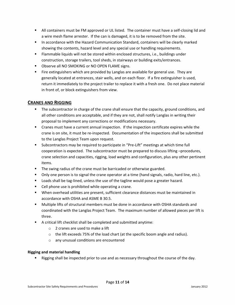
Page 11 of 14 Subcontractor Site Safety Requirements and Procedures January 2012
All containers must be FM approved or UL listed. The container must have a self‐closing lid and a wire mesh flame arrester. If the can is damaged, it is to be removed from the site.
In accordance with the Hazard Communication Standard, containers will be clearly marked showing the contents, hazard level and any special use or handling requirements.
Flammable liquids will not be stored within enclosed structures, i.e., buildings under construction, storage trailers, tool sheds, in stairways or building exits/entrances.
Observe all NO SMOKING or NO OPEN FLAME signs. Fire extinguishers which are provided by Langlas are available for general use. They are
generally located at entrances, stair wells, and on each floor. If a fire extinguisher is used, return it immediately to the project trailer to replace it with a fresh one. Do not place material in front of, or block extinguishers from view.
CRANES AND RIGGING The subcontractor in charge of the crane shall ensure that the capacity, ground conditions, and
all other conditions are acceptable, and if they are not, shall notify Langlas in writing their proposal to implement any corrections or modifications necessary.
Cranes must have a current annual inspection. If the inspection certificate expires while the crane is on site, it must be re‐inspected. Documentation of the inspections shall be submitted to the Langlas Project Team upon request.
Subcontractors may be required to participate in “Pre‐Lift” meetings at which time full cooperation is expected. The subcontractor must be prepared to discuss lifting –procedures, crane selection and capacities, rigging, load weights and configuration, plus any other pertinent items.
The swing radius of the crane must be barricaded or otherwise guarded. Only one person is to signal the crane operator at a time (hand signals, radio, hard line, etc.). Loads shall be tag‐lined, unless the use of the tagline would pose a greater hazard. Cell phone use is prohibited while operating a crane. When overhead utilities are present, sufficient clearance distances must be maintained in
accordance with OSHA and ASME B 30.5. Multiple lifts of structural members must be done in accordance with OSHA standards and
coordinated with the Langlas Project Team. The maximum number of allowed pieces per lift is three.
A critical lift checklist shall be completed and submitted anytime: o 2 cranes are used to make a lift o the lift exceeds 75% of the load chart (at the specific boom angle and radius). o any unusual conditions are encountered
Rigging and material handling Rigging shall be inspected prior to use and as necessary throughout the course of the day.

Page 12 of 14 Subcontractor Site Safety Requirements and Procedures January 2012
If any rigging is found to be worn or damaged, it shall be removed from service immediately. Each subcontractor is responsible for complying with rigging requirements set forth by OSHA, ASME, and the rigging manufacturer.
Rigging equipment should never be used beyond it rated capacity. Stacked materials are to be kept neat and orderly. Materials shall be stacked in a manner to
prevent tipping, falling, shifting, or rolling. Only personnel “Certified” to perform rigging operations as defined by OSHA are allowed to
perform this task on Langlas jobsites.
EQUIPMENT REQUIREMENTS All self‐propelled construction equipment shall be maintained, equipped and operated in accordance with all OSHA and manufacturers’ requirements. Material handling equipment (as defined by OSHA) shall be equipped with Roll‐Over Protective Structures (ROPS) and seat belts. Only authorized and trained personnel shall operate equipment. Cell phone use is prohibited while operating a piece of equipment. Equipment operators and truck drivers shall make a pre‐shift safety inspection of their
equipment. Any conditions that affect safe operation shall be corrected before use. Personnel shall not be transported or ride on equipment or vehicles that are not equipped with
seats for passengers. Riding in the back of pickup trucks or on equipment without the use of a
seatbelt is prohibited. Aerial Lifts Any employee, who is operating or using an aerial lift (scissor or boom), shall be properly trained
in the operation, use, and emergency procedures involved with the lift. Documentation of training shall be made available to Langlas upon request.
Employees shall be tied off correctly in articulating boom lifts. Earthmoving Equipment Bi‐directional earthmoving equipment and motor vehicles with an obstructed view to the rear
shall be equipped with a functioning warning horn and/or an automatic back‐up alarm. Forklifts Only trained and authorized personnel shall operate forklifts. Forklifts shall be operated in accordance with the manufacturer’s specifications and
requirements. Operators will wear seatbelts during forklift operations.
STEEL ERECTION All steel erection activities shall be in compliance with OSHA Subpart R.

Page 13 of 14 Subcontractor Site Safety Requirements and Procedures January 2012
A written “site‐specific erection safety plan” or Job Hazard Analysis Form (to include fall protection) shall be submitted to Langlas prior to the start of work. When special or unusual hazards will be encountered (i.e. work over existing structures, near utilities, or water), the subcontractor will clearly address these issues in the “site‐specific erection safety plan”.
The “Authorization to Proceed with Steel Erection” form shall be provided by Langlas to the subcontractor prior to the commencement of steel erection.
Perimeter cabling shall be no less than a minimum of 3/8” IWRC‐Galvanized, with a minimum of two wire rope clamps at each connection.
Welders shall use appropriate welding hoods, not tinted face shields, and other required PPE. If work is performed within or adjacent to occupied structures, the subcontractor will be
required to make provisions for fire protection and the safe removal of all welding fumes from the building. Documentation of said provisions shall be submitted to Langlas prior to the start of the work.
EXCAVATION WORK All portions of work involving excavations will conform to the Langlas & Associates Utility Locate Policy and requirements of Subpart P‐Excavations. (29 CFR 1926.650) A copy of the Langlas & Associates Utility Locate Policy is available upon request. Each contractor engaged in excavation work must have a person designated as the “Competent
Person” (as defined by OSHA) to enforce compliance with the OSHA Standards for Excavations. The name of that person and their qualifications will be submitted to Langlas before work begins.
No employee shall enter a trench unless it has been determined by the Competent Person to be properly excavated and protected against collapse by means of sloping or benching, shoring, sheeting, the use of a trench box, or by other appropriate system.
Each employee will have the responsibility to stop work and notify others if they perceive that a problem with the excavation or protection system exists or develops.
Excavations will be back‐filled as soon as possible after the completion of work. If excavations cannot be back‐filled, the open trench shall be plated, barricaded, fenced and/or flagged to protect workers, pedestrians and traffic.
CONFINED SPACE ENTRY All activities involving Confined Space Entry shall comply with all applicable OSHA standards. Prior to the start of such an entry, each subcontractor involved in the work shall develop a
Confined Space Entry Procedure. Subcontractors are responsible to train their employees who are involved with confined space
entry. No one may enter a confined space area until properly trained. Subcontractors are required to identify all confined spaces on their project with a sign
identifying the area as a confined space.
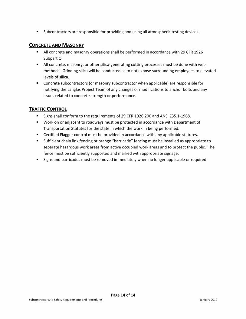
Page 14 of 14 Subcontractor Site Safety Requirements and Procedures January 2012
Subcontractors are responsible for providing and using all atmospheric testing devices.
CONCRETE AND MASONRY All concrete and masonry operations shall be performed in accordance with 29 CFR 1926
Subpart Q. All concrete, masonry, or other silica‐generating cutting processes must be done with wet‐
methods. Grinding silica will be conducted as to not expose surrounding employees to elevated levels of silica.
Concrete subcontractors (or masonry subcontractor when applicable) are responsible for notifying the Langlas Project Team of any changes or modifications to anchor bolts and any issues related to concrete strength or performance.
TRAFFIC CONTROL Signs shall conform to the requirements of 29 CFR 1926.200 and ANSI Z35.1‐1968. Work on or adjacent to roadways must be protected in accordance with Department of
Transportation Statutes for the state in which the work in being performed. Certified Flagger control must be provided in accordance with any applicable statutes. Sufficient chain link fencing or orange “barricade” fencing must be installed as appropriate to
separate hazardous work areas from active occupied work areas and to protect the public. The fence must be sufficiently supported and marked with appropriate signage.
Signs and barricades must be removed immediately when no longer applicable or required.

Employee NameOrientation Complete Area Worked Description of Work
*Competent Person
DAILY REPORT
Project ______________________________ Superintendent ______________________________ Date _____________
Subcontractor _____________________________ Trade ______________________________ # of Employees __________
Foreman _______ Journeyment _______ Apprentice _______ Laborers _______ Operators _______


Department which this is used for: Safety
Purpose of form:
Frequency of Completion?
Who fills it out? Subcontractor Langlas
Who receives this once it is filled out?
Where is it stored after it is completed?
If there are any questions, contact:
Langlas Superintendent or Site Safety Coordinator
They should be kept in a 3‐ring binder on‐site.
Bud Daigle: [email protected] or 406‐577‐1259
Hot Work Permit
Form Explanation and Information
This form is to be filled out daily by anyone performing work involving any welding, burning, cutting, or other spark generating activity. It states our requirements when conduct6ing work of this nat6ure. It is to be filled out anytime there is this type of work involved, regardless of the location of the activity {i.e. in the middle of an excavation] or the frequency of the activity [i.e. cutting metal studs].
This form tells us know exactly where on our projects subcontractors are going to be performing these activities. In case of a fire, we can have a better4 idea of who was responsible for starting it. It clearly states the precautionary measures that they need to take before, during, and after these activities are performed.
Daily per subcontractor per location.

T:\Safety\Field Management Handbook
Hot Work Permit
THIS HOT WORK PERMIT IS REQUIRED FOR ALL TEMPOARY OPERATIONS CREATING HEAT, SPARKS OR OPEN FLAME.
Contractor: __________________________________________ Date: ________________________ Jobsite: ______________________________ Specific Work Location: _________________________ Competent Person Responsible for Operations: Print Name___________________________________ I understand the requirements of this Hot Work Permit. Sign: _________________________________ TYPE OF WORK PERFORMED: ___ Welding ___ Burning ___ Cutting ___ Other ___________________________________ Start Time______________________ AM/PM Finish Time_________________________ AM / PM REQUIRED PRECAUTIONS:
Fire extinguisher present & charged Fire watch must be present
Floor Broom Swept Fire watch trained on equipment
Hot work equipment in good condition Fire watch has no other duties
Flammables and combustibles removedprotected
Work area inspected above, below, & adjacen
FIRE WATCH MUST BE MAINTAINED FOR 60 MINUTES AFTER WORK COMPLETED Other Precautions Taken: _______________________________________________________________ PERMIT APPROVAL I verify the above location has been examined and the required precaution have been taken to safety Perform the Hot Work listed above: ___________________________________________________ _____________________________________ Approval Signature (Langlas Construction Rep) Date
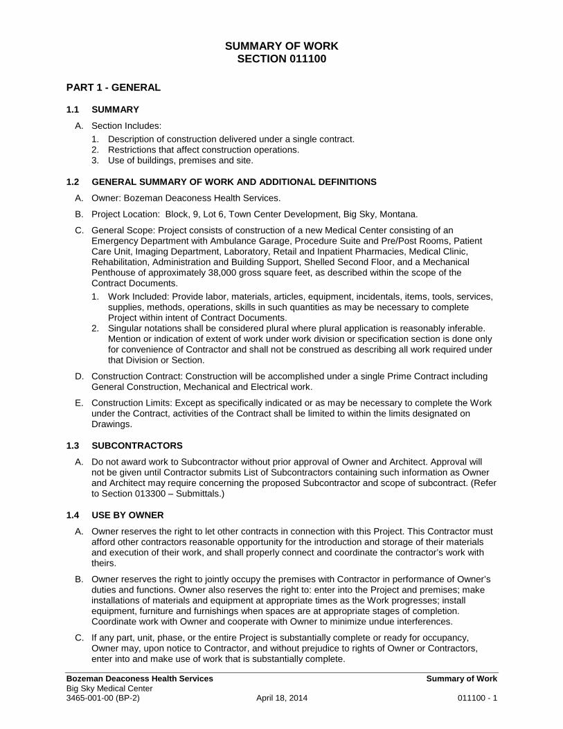
Bozeman Deaconess Health Services Summary of Work Big Sky Medical Center 3465-001-00 (BP-2) April 18, 2014 011100 - 1
SUMMARY OF WORK SECTION 011100
PART 1 - GENERAL
1.1 SUMMARY
A. Section Includes:
1. Description of construction delivered under a single contract. 2. Restrictions that affect construction operations. 3. Use of buildings, premises and site.
1.2 GENERAL SUMMARY OF WORK AND ADDITIONAL DEFINITIONS
A. Owner: Bozeman Deaconess Health Services.
B. Project Location: Block, 9, Lot 6, Town Center Development, Big Sky, Montana.
C. General Scope: Project consists of construction of a new Medical Center consisting of an Emergency Department with Ambulance Garage, Procedure Suite and Pre/Post Rooms, Patient Care Unit, Imaging Department, Laboratory, Retail and Inpatient Pharmacies, Medical Clinic, Rehabilitation, Administration and Building Support, Shelled Second Floor, and a Mechanical Penthouse of approximately 38,000 gross square feet, as described within the scope of the Contract Documents.
1. Work Included: Provide labor, materials, articles, equipment, incidentals, items, tools, services, supplies, methods, operations, skills in such quantities as may be necessary to complete Project within intent of Contract Documents.
2. Singular notations shall be considered plural where plural application is reasonably inferable. Mention or indication of extent of work under work division or specification section is done only for convenience of Contractor and shall not be construed as describing all work required under that Division or Section.
D. Construction Contract: Construction will be accomplished under a single Prime Contract including General Construction, Mechanical and Electrical work.
E. Construction Limits: Except as specifically indicated or as may be necessary to complete the Work under the Contract, activities of the Contract shall be limited to within the limits designated on Drawings.
1.3 SUBCONTRACTORS
A. Do not award work to Subcontractor without prior approval of Owner and Architect. Approval will not be given until Contractor submits List of Subcontractors containing such information as Owner and Architect may require concerning the proposed Subcontractor and scope of subcontract. (Refer to Section 013300 – Submittals.)
1.4 USE BY OWNER
A. Owner reserves the right to let other contracts in connection with this Project. This Contractor must afford other contractors reasonable opportunity for the introduction and storage of their materials and execution of their work, and shall properly connect and coordinate the contractor’s work with theirs.
B. Owner reserves the right to jointly occupy the premises with Contractor in performance of Owner’s duties and functions. Owner also reserves the right to: enter into the Project and premises; make installations of materials and equipment at appropriate times as the Work progresses; install equipment, furniture and furnishings when spaces are at appropriate stages of completion. Coordinate work with Owner and cooperate with Owner to minimize undue interferences.
C. If any part, unit, phase, or the entire Project is substantially complete or ready for occupancy, Owner may, upon notice to Contractor, and without prejudice to rights of Owner or Contractors, enter into and make use of work that is substantially complete.

Bozeman Deaconess Health Services Summary of Work Big Sky Medical Center 3465-001-00 (BP-2) April 18, 2014 011100 - 2
1.5 MAINTAINING SERVICES AND FUNCTIONS
A. Work at Occupied Facilities: After Owner's occupancy (full or partial) of Project or unit, stage, phase or area, work remaining to be accomplished in the occupied spaces shall be done in cooperation with, and approval by, Owner and scheduled in advance with Owner. In general, work in occupied spaces shall be done when the space is not in use, such as after hours in administrative areas or public spaces when public use hours are over for the day, unless specifically approved by Owner. Where necessary, overtime shall be used if work cannot reasonably be accomplished during normal work periods, at no extra cost to Owner. Perform work in occupied areas in a manner and at such time as will not significantly interfere with, hamper or inconvenience Owner's program or functions.
1.6 PERFORMANCE/PAYMENT BOND
A. Owner reserves the right to require a bond in accordance with General Conditions and Supplementary Conditions. Provide on form specified.
1.7 OTHER BONDS, PERMITS, FEES
A. Provide and pay for bonds, fees and permits that may be required, including bonds, permits and fees required by municipalities, including connecting fees, to directly accomplish work under this project.
1.8 WARRANTIES
A. In the event of conflict, inconsistency, or difference between a warranty issued by a supplier or contractor and terms of specifications, Owner, if it becomes necessary to enforce terms and provisions of warranty or specifications, may elect to enforce either submitted warranty or specifications.
1.9 ELECTRONIC FILES
A. Upon request, one copy of electronic files in Architect’s current file format, including applicable layers, for each issue (bid packages, construction packages, addenda, etc.) will be provided via e-mail, CD, or website posting at Architect’s option to General Contractor at no charge for:
1. Architectural floor plans 2. Reflected ceiling plans 3. Structural framing plans 4. HVAC plans 5. Plumbing plans 6. Lighting plans 7. Signal/System plans 8. Power plans. 9. Civil Plans
B. Additional documents not listed or additional copies of electronic files are available upon request with advance payment of applicable fee(s) and subject to conditions of use. Contact Architect for schedules of fees and additional details about conditions. Subcontractors and others can obtain copies of electronic files from General Contractor.
C. Electronic files and information therein are instruments of service and works in progress created for this Project and not to be used for other projects, additions to this project or completion of this Project by others.
D. Signed and sealed original hard copy Drawings, Specifications and other documents as defined by General Conditions are Contract Documents. Electronic files are not Contract Documents and may be subject to manipulation beyond Architect’s control. Therefore, Architect cannot verify that electronic files accurately or completely reflect Contract Documents, actual construction or field conditions. Each user of electronic files must determine accuracy, completeness and suitability for its intended use.
E. Electronic files are subject to discrepancies as a result of numerous factors including but not limited to transmission and translation errors resulting from differences in software, hardware and other
Bozeman Deaconess Health Services Summary of Work Big Sky Medical Center 3465-001-00 (BP-2) April 18, 2014 011100 - 3
equipment related problems, disc or server malfunctions, data corruption during transmission through website or email and user error. Neither Architect nor Owner shall be responsible for such discrepancies.
F. Architect makes no representation regarding accuracy, completeness or permanence of electronic files. Changes to Contract Documents may not be incorporated into electronic files including without limitation, Addenda information or revisions made after date indicated on electronic files.
G. By accepting electronic files, user covenants not to sue, and agrees to indemnify and hold harmless Architect and Owner from costs (including attorneys’ fees), claims or causes of action be it tort, breach of contract or otherwise that result from the use of electronic files, and waives claims for consequential and/or liquidated damages against Architect and Owner.
H. Architect and Owner provide no warranties, express or implied with respect to electronic files, including but not limited to, Spearin type warranties, warranties of merchantability and/or fitness for a particular purpose.
I. Use of electronic files provided by Architect does not obviate Contractor, subcontractor/installer or supplier from responsibility for proper checking and coordination of dimensions, details, member sizes, quantities and other requirements to facilitate complete and accurate fabrication, installation and completion of Work.
J. Providing electronic files by Architect is not to be construed to be in derogation of reserved or intellectual property rights.
1.10 COPIES OF DRAWINGS AND SPECIFICATIONS
A. Drawings and Specifications will be made available to Contractor via an electronic distribution service. Subcontractors obtain documents from Contractor. Subcontractors are responsible for costs associated with hard copy printing drawings from this service. Provide one set for the on-site set to record changes as Record Set.
1.11 USE OF PREMISES - SPECIAL CONSIDERATIONS, REQUIREMENTS AND CONSTRAINTS 1. Work Over Finished Floors: Where work is performed over finished floors (i.e. ceramic tile,
concrete, VCT) or where area is used as a passage, provide hardboard or plywood cover to protect against damage or stains. Covering to be provided by General Contractor or as assigned in appropriate Bid Packages. Refer to Bid Scopes.
B. Work Over Carpeting: Certain finishing operations may occur over installed carpet areas. Maintain carpet covering free from holes or gaps. At hard use areas, such as passages, also provide hardboard or plywood surfacing to prevent damage. Use extreme care in working over carpeting and its covering.
C. Safety Program: Develop a safety program and provide a first aid kit in accessible locations on site for temporary on-site first aid. Contractor is responsible for safety of persons and property and compliance with applicable statutes, rules, regulations, and orders for work under this Contract.
D. Temporary Plywood Enclosures, General: Supported, sound plywood of appearance acceptable to Architect. Insulate enclosures at building openings where temporary enclosure serves as building exterior wall.
E. Accomplish work in streets in conformance with Municipality requirements and to a schedule as Municipality may require. Contractor must make arrangements with Municipality.
F. Snow Removal: Remove snow from the building work areas, storage areas, and access routes after each period of snowfall to prevent the accumulation of snow and ice from impeding job progress or creating unsafe conditions.
1.12 USE OF PREMISES - BROKEN GLASS
A. Contractor is responsible for glass of the new building. Provide protection for glass, except Subcontractors shall protect their own glass.
B. Near completion of Project, Contractor must replace broken, cracked, scratched or otherwise damaged or faulty glass, without additional reimbursement. Replace glass damaged by welding

Bozeman Deaconess Health Services Summary of Work Big Sky Medical Center 3465-001-00 (BP-2) April 18, 2014 011100 - 4
splatter. Cost of replacing glass broken or damaged by Subcontractors shall be paid for by party causing damage.
1.13 USE OF PREMISES - CLEAN CONDITIONS
A. References: Refer to General Conditions for general cleaning requirements, Section 017700 for Project Closeout Clean-up and for additional temporary closure requirements.
B. General: Contractor and subcontractors shall maintain clean conditions in areas of existing buildings and where new construction interfaces with existing buildings. Maintain areas free of accumulations of combustible materials. Provide good housekeeping and regular cleaning to maintain areas clean and free of debris. Provide proper closures between areas under construction including closures and measures to prevent spread of dust or other contamination.
1.14 HAZARDOUS SUBSTANCES AND HARMFUL PHYSICAL AGENTS
A. Where work of this project involves possible hazardous substances or harmful physical agents, exercise extreme care to avoid damage and preserve safety of personnel.
B. Regulations concerning availability of information and employee training in use and handling of "hazardous substances" and "harmful physical agents" are governed by Employee Right-to-Know Act of (1983 unless otherwise revised or updated; or amended by local jurisdictions).
C. Regulations governing handling of asbestos-containing materials and disposal of asbestos-containing debris are:
1. Code of Federal Regulations, Title 29, U.S. Department of Labor - Occupational Safety and Health Administration (OSHA), Section 1910.1001 - Asbestos.
2. Local pollution control agency Rules for Emission Standards for Asbestos.
1.15 GENERAL PROTECTION AND SAFETY
A. References: Refer to General Conditions of the Contract for general requirements.
B. General: In accordance with best construction practices, Contractor is solely and completely responsible for conditions of job site, including safety of persons and property affected directly or indirectly by contractor’s operations during performance of Work. This requirement shall apply continuously 24 hours per day until acceptance of Work by Owner and shall not be limited to normal working hours.
1.16 SAFETY DIRECTOR - FIRE AND ACCIDENT
A. Safety Director: Appoint a responsible employee to act as Safety Director (fire and accident or separate individuals for each) whose duty it shall be to prevent accidents and minimize fire hazards and to enforce safety precautions. Safety Director shall develop procedures and regulations to guide Contractor, subcontractors and workers. With particular respect to existing buildings, facilities, and Owner's staff, Safety Director shall consult with and be guided by directions of Owner.
B. Compliance: Contractor and Subcontractors shall conform to and abide by requirements of Safety Director.
C. Inspection: Safety Director shall periodically inspect spaces of work under this Contract and operations of Contractor and list hazards to be removed or corrected. These shall be reported to Owner, Contractor and responsible subcontractors, who shall promptly remove or correct hazards.
D. Site Meetings: Safety Director shall hold accident and fire prevention meetings at least once a month with representatives of various trades employed to insure employees understand and comply with programs.
1.17 FIRE SAFETY PRECAUTIONS
A. Reference: Refer to General Conditions for general requirements.
B. General: Contractor and Safety Director shall recognize the utmost importance of extraordinary precautions to prevent a fire in or adjacent to functioning and occupied building. Contractor, subcontractors and workers shall exercise extreme care to maintain and exercise fire safety

Bozeman Deaconess Health Services Summary of Work Big Sky Medical Center 3465-001-00 (BP-2) April 18, 2014 011100 - 5
precautions through work. This shall include providing sufficient firefighting devices, watchmen, standby helpers or other precautions during construction, in use of temporary heat, welding, bracing, sweating, testing or other phases of work. Refer to Section 015200 for temporary firefighting devices to be provided under Contract.
PART 2 - PRODUCTS Not Used.
PART 3 - EXECUTION Not Used.
END OF SECTION


Bozeman Deaconess Health Services Alternates Big Sky Medical Center 3465-001-00 (BP-2) April 18, 2014 012300 - 1
SECTION 012300 ALTERNATES
PART 1 GENERAL
1.1 SUMMARY
A. Section Includes:
1. Alternates.
1.2 DEFINITIONS
A. Alternate: Amount proposed by bidders and stated on Bid Form for certain work defined in Bidding Requirements that may be added to or deducted from Base Bid amount if Owner decides to accept corresponding change either in amount of construction to be completed or in products, materials, equipment, systems, or installation methods described in Contract Documents.
1. Cost or credit for each alternate is net addition to or deduction from Contract Sum to incorporate alternate into Work. No other adjustments are made to Contract Sum.
1.3 PROCEDURES
A. Submit alternate price for each Alternate listed on Bid Form.
1. State dollar amount of each Alternate to be added to or deducted from Base Bid or indicate “No Change” in Base Bid sum.
B. Under each Alternate, include work of all trades for Contract as they may be affected and make adjustments to accommodate changes.
1. In executing work, make provisions for future completion, unless otherwise specified
C. Coordination: Modify or adjust affected adjacent work as necessary to completely integrate work of alternate into Project.
1. Include as part of each alternate, miscellaneous devices, accessory objects, and similar items incidental to or required for a complete installation whether or not indicated as part of alternate.
D. Notification: Immediately following award of Contract, notify each party involved, in writing, of status of each alternate. Indicate if alternates have been accepted, rejected, or deferred for later consideration. Include complete description of negotiated modifications to alternates.
E. Execute accepted alternates under the same conditions as other work of Contract.
F. Schedule: A Schedule of Alternates is included at end of this Section. Specification Sections referenced in schedule contain requirements for materials necessary to achieve work described under each alternate.
G. Owner reserves right to reject Alternates. Owner may accept Alternates regardless of order or combination and to determine low bidder on the basis of sum of Base Bid and accepted Alternates.
1. Alternate descriptions are general only and are not intended to be complete tabulation of Work which may be affected by Alternate.
2. Carefully examine Contract Documents and determine exact extent of Work affected by Alternate.
3. Detailed requirements may be specified in various Sections of Specifications.
H. Alternate prices shall not increase by change in material prices, wage rates, or other escalatory factors. Alternate prices are “all inclusive”, including labor, material supervision, tools, equipment, taxes, overhead, profit, and other things necessary.
1. Where Alternate may involve another Alternate, depending on acceptance, consider each Alternate as change to Contract Sum, with no considerations for effect on other Alternates.
I. Owner reserves right to delay decisions on Alternates and to accept or reject Alternates within 60 days after bid date unless longer Alternate time frames are indicated.

Bozeman Deaconess Health Services Alternates Big Sky Medical Center 3465-001-00 (BP-2) April 18, 2014 012300 - 2
1.4 SCHEDULE OF ALTERNATES
A. Alternate Bid No.1: State the price to provide fully adhered single ply roofing Section 075305 in lieu of mechanically attached single ply roofing Section 075307 for the entire roof.
B. Alternate Bid No. 2: State the price not to include the Solar Control Devices (SCD-1) Section 107113, as indicated on the South Elevation of the Patient Care Unit. Provide related structure as indicated in detail 16/S710 in lieu of detail 5/S701.
PART 2 PRODUCTS Not Used.
PART 3 EXECUTION Not Used.
END OF SECTION

Bozeman Deaconess Health Services Submittal Procedures Big Sky Medical Center 3465-001-00 (BP-2) April 18, 2014 013300 - 1
SECTION 013300 SUBMITTAL PROCEDURES
PART 1 GENERAL
1.1 SUMMARY
A. Section Includes:
1. Procedures for submittals.
B. Related Sections:
1. General Conditions: General Requirements. 2. Section 011100 - Summary of Work. 3. Section 013100 - Project Management and Coordination. 4. Section 017700 - Closeout Procedures. 5. Section 017800 - Closeout Submittals. 6. Section 013310 - Submittal Transmittal.
1.2 SUBMITTAL SCHEDULE
A. Prepare and submit "Submittal Schedule" within 30 days after award of Contract. Include following information.
1. Specification Section Number. 2. Type of submittal required. 3. Estimated time for submittal.
B. Coordinate, organize and plan submittal schedule so submittals are sent with appropriate time allowed for adequate professional review (minimum 10 working days) and so submittals do not accumulate into unusually large groups.
C. Some submittals may require additional time for routing and review including, but not limited to, following:
1. Unusually large groups of submittals. 2. Curtainwall and windows. 3. Hardware and doors. 4. Submittals that need to be routed to multiple disciplines and consultants.
1.3 TRANSMITTAL FORM
A. Send submittals with "Submittal Transmittal Form" Section 013310, or similar forms as customarily used by the Contractor completely filled out with appropriate information as indicated.
B. Submittals sent without properly completed "Submittal Transmittal Form" will be considered incomplete and marked "Not Accepted" and returned without review.
C. Send separate transmittal forms for each Section:
1. Shop Drawings. 2. Product Data. 3. Samples.
D. If shop drawings, samples or product data describe the same product or item, send submittals together under same transmittal otherwise send each type submittal under separate transmittals.
1.4 SUBMITTAL ACCEPTANCE
A. Refer to General Conditions for scope of submittal review and acceptance.
B. Substitutions or Contract modifications shall not be made in submittals. Exceptions and variations must be clearly noted on submittal and accompanied by the appropriate supporting forms. Follow documented procedures for substitutions or Contract modifications and send with submittal if a change is being proposed. Approval of a submittal with substitutions or modifications included but that have not been specifically and individually approved does not constitute acceptance of the
Bozeman Deaconess Health Services Submittal Procedures Big Sky Medical Center 3465-001-00 (BP-2) April 18, 2014 013300 - 2
substitution and Contractor will be responsible for exception or variations not in compliance with Contract Documents.
C. For submittals need to be resubmitted after the first review, Contractor will be responsible for Architects fees for more than the second review unless otherwise agreed.
D. Maintain copies of "Approved” and "Conditionally Approved" submittals with record set per 017800.
E. "Approved" submittals have no exceptions noted. One set of accepted submittals will be returned to Contractor, unless requested otherwise and multiple copies have been provided for such return. Make appropriate copies for use and distribution.
F. "Conditionally Approved" submittals have exceptions noted but resubmission is not required. Make appropriate copies for use and distribution.
G. "Not Approved" submittals are incomplete and/or need corrections. Complete and/or correct and resubmit until final acceptance is obtained.
H. "Received” means submittals are for information only and have not been reviewed.
I. "Not Reviewed" means submittals were not required and have not been reviewed or were provided for information only.
1.5 CONTRACTOR'S PLAN OF OPERATION
A. Submit at Pre-Construction Conference. Refer to Section 013100.
B. Outline in writing approach to meeting schedule for completing Work.
C. Plan to include, but not limited to, following:
1. Sequence of Work. 2. Construction Schedule. 3. Schedule of Submittals. 4. Schedule of Temporary Utilities. 5. Staging requirements/street permits. 6. Normal work hours. 7. Parking exceptions 8. Material delivery coordination. 9. Name of person to be liaison to adjacent property Owners. 10. Name of duly authorized representative with whom business may be conducted in connection
with administration of Contract. 11. Name of duly authorized superintendent written notices may be given in accordance with
Conditions of the Contract. 12. Labor and equipment availability 13. List of Subcontractors 14. Names of contact persons with Owner, Architect and Contractor 15. Proposed schedule of Progress Meetings in accordance with Section 013100 and schedule of
submittals per Section 013310 and payment requests per Section 012900, and other reports required by Contract Documents.
1.6 COORDINATION
A. Send submittals in logical groups of related items including but not limited to the following groups:
1. Submittal schedule, list of materials, list of subcontractors, schedule of values 2. Doors, frames and hardware. 3. Glass and curtain wall system. 4. Closeout submittals: Refer to Section 017800.
1.7 DISTRIBUTION
A. Contractor is responsible for duplication and distribution of accepted submittals including shop drawings. Exchange directly with subcontractors and others involved, not through Owner or Architect.

Bozeman Deaconess Health Services Submittal Procedures Big Sky Medical Center 3465-001-00 (BP-2) April 18, 2014 013300 - 3
B. Provide and exchange submittals as needed to coordinate Work.
C. Provide copies to Owner if Owner requests copies during construction. Otherwise Owner will receive accepted submittals as part of Record Set submitted during project closeout.
1.8 ELECTRONIC SUBMITTALS
A. Electronic submittals is the preferred method of review. Follow these procedures:
1. Provide one pdf file for each submittal to Submittals Coordinator. PDF file must be unlocked, editable and printable to accommodate electronic mark-ups or printing a hard copy from mark-up.
2. Electronic submittals are to be complete and self-contained with each item requiring Architect’s action. a. Web links or other electronic submittals requiring Architect to surf websites or navigate to
find documents on websites or posting services are not acceptable. b. If construction phase file hosting services or programs are used such as Prolog, Primavera
or documents hosting programs may be considered subject to coordination with Architect. c. Such procedures should not require Architect to search for submittals but should follow
procedures that are the electronic equivalent of hard copy submittals sent by Contractor to Architect in a manner acceptable to Architect.
3. Where project data is intended to show colors, provide original hard copy only. See Product Data herein. No electronic submittals for color submittals.
4. Submit samples according to Samples article herein. No electronic submittals for samples will be permitted.
5. Architect will return one marked up electronic submittal for Contractor to process and distribute to subcontractors and for Owner according to Distribution article requirements herein, unless alternate arrangements have been made.
6. On each electronic submittal, provide Contractor review and approval stamp on each submittals.
1.9 SHOP DRAWINGS
A. Use of Architect’s Drawings: Do not reproduce Architect's drawings (whether CADD files, electronic files, hard copy drawings or other publication method) to serve as shop drawings until Architect’s written permission is received and then only under the following conditions.
1. Use is subject to terms and conditions included in written permission. 2. Use only where necessary to indicate general location of a specific fabricated item. 3. Remove extraneous notes and information from Drawing before inclusion in submittal. Only
show information related to fabrication, erection, installation, application of components, products or systems being produced. Do not include Architect's title block or other information identifying Architect.
4. Submitted drawing should only include information intended to be reviewed and accepted. 5. Refer to Summary of Work for additional information on Electronic files.
B. Drawings that include unnecessary information will be marked "Not Reviewed" or "Not Approved" and returned.
C. Shop drawings submitted without requested information and without Contractor's approval will not be reviewed and will be returned to Contractor marked "Not Approved."
D. Drawings Submittal Requirements:
1. Submit 1 opaque copies of each drawing. a. Architect will retain a copy.
2. Provide additional copies for other contractors for purposes of information and coordination. 3. Number in submittal sequence. 4. Include contractor's stamp of approval, as evidence that drawings are approved in accordance
with General Conditions except that field dimensions must be verified prior to approval and submittal.
5. Show field verified dimensions on final shop drawings and identify verified dimensions. 6. Show actual adjacent construction and how each item coordinates with other subcontractors,
trades and suppliers.

Bozeman Deaconess Health Services Submittal Procedures Big Sky Medical Center 3465-001-00 (BP-2) April 18, 2014 013300 - 4
7. Drawings must be clear, sharp and readable quality acceptable to Architect/Engineer. 8. Provide clear space on each drawing of not less than 16 square inches for Architect's stamp. 9. Transmit in mailing tubes.
E. Maintain accepted shop drawings as part of "Record Set." See 017800.
1.10 PRODUCT DATA AND EQUIPMENT BROCHURES
A. Provide multiple originals of brochures, cuts, etc., if they are multi-page bound catalogs which would be difficult to photocopy or if they are intended to illustrate color or other appearance characteristics which cannot be adequately represented by photocopies.
B. Photocopies of original brochures are acceptable except as specified above. Photo copies must be clear and readable. Unreadable or unclear photocopies will be returned "Not Accepted."
C. Provide layout drawings where necessary for field use or as required by Architect.
D. Number of Copies of Product Data:
1. Submit 1 minimum unless otherwise specified. Submit multiple copies of color brochures and catalogs intended to illustrate color or other design qualities. a. Architect will retain 1 copy.
2. Submit additional copies required for 2 Owner's manuals per 017800. 3. Additional copies for other contractors for purposes of information and coordination. 4. Number in submittal sequence. 5. Include contractor's stamp of approval, as evidence that drawings are approved in accordance
with General Conditions (including field dimensions). 6. Indicate field verified information as applicable. 7. Provide clear space of not less than16 square inches for Architect's stamp.
E. Provide an index of each page in submittal with space for notes and acceptance stamps.
F. Warranties:
1. Where warranty is indicated, submit manufacturers' sample warranty with shop drawings. 2. Submit actual executed warranties or guarantees per Section 017700 and 017800.
1.11 SAMPLES
A. Deliver samples of materials, equipment, assemblies and components as required by specifications to Architect/Engineer with delivery costs prepaid. At Architect's/Engineer's direction, remove samples after approval.
1. Provide samples representative of actual product including finishes and other specified characteristics.
2. Indicate type of construction and quality proposed for installation in Project.
B. Number Samples:
1. Submit 3 samples unless otherwise specified. a. One set of samples to be retained by Architect.
2. Provide additional samples for other contractors for purposes of information and coordination.
C. Maintain record samples of accepted samples with other record documents at project site.
1.12 LIST OF MATERIALS
A. Submit within 10 days after award of Contract and prior to purchase.
B. Submit 1 copy of complete list of materials, products, and equipment proposed to be used to Architect/Engineer for acceptance.
C. Do not order materials or equipment until proposed list of materials is accepted.
D. Materials and equipment are subject to Architect's and Owner's acceptance.
E. Arrange list in order of specification sections and in form indicated by Architect/Engineer.
1. Items listed shall fully conform to project requirements and specifications.

Bozeman Deaconess Health Services Submittal Procedures Big Sky Medical Center 3465-001-00 (BP-2) April 18, 2014 013300 - 5
2. Specifically identify each material, product or equipment item by manufacturer, brand and model and other identifying designations including those where only 1 material or product is specified.
3. Name products specified by reference standards, described by performance requirements and descriptive language.
4. Do not list "as specified."
F. Where 2 or more makes or kinds of items are named in specifications (or additional names are listed in an addendum), state which particular make or kind of each item is to be provided.
G. If list is not received within 30 days, mechanical and electrical equipment under Divisions 21, 22, 23, 25, 26, 27, 28, 40, 41, 42, 43, 44, 45, and 48 will be as scheduled.
1.13 LIST OF SUBCONTRACTORS
A. Submit within 30 days after award of Contract, and prior to execution of Contract.
B. Submit with List of Materials.
C. Submit 1 copies of a complete list.
D. Do not execute subcontracts until proposed list of subcontractors is accepted by Owner.
E. List to include the following information and be in form indicated by Owner.
1. Description of work proposed to be done by subcontract. 2. Names of subcontractors and major material suppliers proposed to perform portions of Work. 3. Names of sub-subcontractors of mechanical and electrical subcontractors. 4. Include proposed sub-subcontractors for other trades as requested by Owner.
F. Proposed subcontractors or sub-subcontractors (and material supplier installers) shall be established, reputable firms of recognized standing with a record of successful and satisfactory past performance with type work and/or items proposed to be provided or installed by them.
1. Only those subcontractors (and sub-subcontractor when appropriate) who Architect and Owner have no reasonable objection to shall be used on Work.
G. Reasonable objection may arise when, in opinion of Architect or Owner, there exists a rational belief that proposed subcontractor, sub-subcontractor or material supplier:
1. Cannot provide materials, equipment, facilities or other products as specified or required by Contract Documents;
2. Cannot provide labor and skill necessary to accomplish part of Work for which they are proposed, including but not limited to quality of work;
3. Lacks adequate and appropriate experience for that part of Work proposed, including materials or methods required;
4. Has previously failed to perform in timely or satisfactory manner, including in cooperation and in necessary services after project completion;
5. Proposes deviations in materials or methods that are unacceptable to Architect or Owner, such as proposing materials or products that were not specified or not listed in addenda;
6. Cannot satisfactorily perform part of Work for which contractor is proposed, within time schedule, due to size of organization or existing work load.
7. Cannot demonstrate ability through quality of representative work to perform part of Work for which contractor is being considered;
8. Of questionable integrity; 9. Shows evidence of similar considerations bearing on possibility of unsatisfactory performance.
H. If Owner or Architect has a reasonable objection to person or entity proposed by Contractor to do portion of Work, Contractor must submit substitute to whom neither Owner nor Architect has reasonable objection; no increase in Contract Sum shall be allowed as a result of such substitution.
I. After acceptance of proposed list, no change of subcontractor, sub-subcontractor or supplier not objected to by Architect or Owner, shall be made, except for cause acceptable to Architect and Owner.
1. In event of a proposed change, submit reasons for change, in writing, along with alternate proposed subcontractor, sub-subcontractor or material supplier.

Bozeman Deaconess Health Services Submittal Procedures Big Sky Medical Center 3465-001-00 (BP-2) April 18, 2014 013300 - 6
2. Proposed change is subject to conditions of this Article and requirements of General Conditions.
1.14 CLOSE-OUT SUBMITTALS
A. Submit documents specified under Sections 017700 and 017800.
B. Submit two (2) copies of operating instructions and maintenance manuals to Owner at time of Owner's instructions.
1.15 OTHER SUBMITTALS
A. Provide other required submittals as specified.
PART 2 PRODUCTS Not used.
PART 3 EXECUTION Not used.
END OF SECTION

Bozeman Deaconess Health Services Submittal Transmittal Big Sky Medical Center 3465-001-00 (BP-2) April 18, 2014 013310 - 1
SECTION 013310 SUBMITTAL TRANSMITTAL
To: HGA Architects and Engineers, LLC From: (Contractor)
Attn: Submittals Coordinator (Address) 420 5th Street North, Suite 100 (Address) Minneapolis, Minnesota 55401 (City, State)
Owner: Bozeman Deaconess Health Services Date: Project: Big Sky Medical Center HGA Commission No.: 3465-001-00 Previous Submittal Date: Incomplete submittals will be returned "Not Accepted." See General Conditions and 013300 for requirements. The following submittal(s) is (are) attached for your review as required by the Contract Documents. SHOP DRAWINGS
No. copies submitted. Submit minimum 1 copy per 013300; complete the following information:
Partial Complete Preliminary Final
List of Drawings:
Specification Section: Article & Paragraph:
Description of Item:
Manufacturer:
Supplier’s Name: Telephone Number: PRODUCT DATA AND QUALITY CONTROL
No. copies submitted. Submit minimum 1 copy per 013300; complete the following information:
Partial Complete Preliminary Final
List of Items:
Specification Section: Article & Paragraph:
Description of Item:
Manufacturer:
Supplier’s Name: Telephone Number: SAMPLES
No. copies submitted. Submit minimum 3 copies per 013300; complete the following information:
Partial Complete Preliminary Final
List of Items:
Specification Section: Article & Paragraph:
Description of Item:
Manufacturer:
Supplier’s Name: Telephone Number:
Submitted by: Company Name: Phone: Signature:
END OF SECTION


Bozeman Deaconess Health Services References Big Sky Medical Center 3465-001-00 (BP-2) April 18, 2014 014200 - 1
SECTION 014200
REFERENCES
PART 1 GENERAL
1.1 SUMMARY
A. Section Includes:
1. Reference to standards and codes.
B. Related Sections:
1. General Conditions. 2. Section 016210 - Product Options and Substitution Requirements.
1.2 DEFINITIONS
A. "Approved": The term "approved," when used to convey Architect's action on Contractor's submittals, applications, and requests, is limited to Architect's duties and responsibilities as stated in the Conditions of the Contract.
B. "Directed": Terms such as "directed," "requested," "authorized," "selected," "approved," "required," and "permitted" mean directed by Architect, requested by Architect, and similar phrases.
C. "Indicated": The term "indicated" refers to graphic representations, notes, or schedules on Drawings or to other paragraphs or schedules in Specifications and similar requirements in the Contract Documents. Terms such as "shown," "noted," "scheduled," and "specified" are used to help the user locate the reference.
D. "Regulations": The term "regulations" includes laws, ordinances, statutes, and lawful orders issued by authorities having jurisdiction, as well as rules, conventions, and agreements within the construction industry that control performance of the Work.
E. "Furnish": The term "furnish" means to supply and deliver to Project site, ready for unloading, unpacking, assembly, installation, and similar operations.
F. "Install": The term "install" describes operations at Project site including unloading, temporarily storing, unpacking, assembling, erecting, placing, anchoring, applying, working to dimension, finishing, curing, protecting, cleaning, and similar operations.
G. "Provide": The term "provide" means to furnish and install, complete and ready for the intended use.
H. "Installer": An installer is the Contractor or another entity engaged by Contractor as an employee, Subcontractor, or Sub-subcontractor, to perform a particular construction operation, including installation, erection, application, and similar operations.
I. The term "experienced," when used with an entity, means having successfully completed a minimum of 5 previous projects similar in size and scope to this Project; being familiar with special requirements indicated; and having complied with requirements of authorities having jurisdiction.
J. Using a term such as "carpentry" does not imply that certain construction activities must be performed by accredited or unionized individuals of a corresponding generic name, such as "carpenter." It also does not imply that requirements specified apply exclusively to trades people of the corresponding generic name.
K. "Project site" is the space available for performing construction activities. The extent of Project site is shown on Drawings and may or may not be identical with the description of the land on which Project is to be built.
1.3 APPLICABLE GOVERNING STANDARDS
A. Code Overview: Code plans identifying Occupancy Types, Occupant Loads, Construction Type and Exiting Components should be consulted for additional information.
Bozeman Deaconess Health Services References Big Sky Medical Center 3465-001-00 (BP-2) April 18, 2014 014200 - 2
1. Building Code: 2009 International Building Code as amended and adopted by Administrative Rules of Montana (ARM) Title 24, Chapter 301.
2. Mechanical Code: 2009 International Mechanical Code as amended and adopted by Administrative Rules of Montana (ARM) Title 24, Chapter 301.
3. Fuel Gas Code: 2009 International Fuel Gas Code as amended and adopted by Administrative Rules of Montana (ARM) Title 24, Chapter 301.
4. Energy Code: International Energy Conservation Code as amended and adopted by Administrative Rules of Montana (ARM) Title 24, Chapter 301.
5. Plumbing Code: 2009 Uniform Plumbing Code as amended and adopted by Administrative Rules of Montana (ARM) Title 24, Chapter 301.
6. Electrical Code: 2011 National Electric Code as amended and adopted by Administrative Rules of Montana (ARM) Title 24, Chapter 301.
7. Elevator Code: Safety Code for Elevators and Escalators, ANSI A17.1 2004 Edition, A17.1a 2005 Addenda, and ASME A17.1S, 2005 Supplement.
8. Accessibility Code: ICC/ANSI A117.1 as amended and adopted by Administrative Rules of Montana (ARM) Tile 24, Chapter 301, Rule 901.
9. Health Department Code: NFPA 101 Life Safety Code, 2000 10. Life Safety Code:
a. NFPA Life Safety Code 101 - 2000 edition, is consulted when building code is silent on an issue.
1.4 INDUSTRY STANDARDS
A. Applicability of Standards: Unless the Contract Documents include more stringent requirements, applicable construction industry standards have the same force and effect as if bound or copied directly into the Contract Documents to the extent referenced. Such standards are made a part of the Contract Documents by reference.
B. Publication Dates: Comply with standards in effect as of date of the Contract Documents, unless otherwise indicated.
C. Conflicting Requirements: If compliance with two or more standards is specified and the standards establish different or conflicting requirements for minimum quantities or quality levels, comply with the most stringent requirement. Refer uncertainties and requirements that are different, but apparently equal, to Architect for a decision before proceeding.
1. Minimum Quantity or Quality Levels: The quantity or quality level shown or specified shall be the minimum provided or performed. The actual installation may comply exactly with the minimum quantity or quality specified, or it may exceed the minimum within reasonable limits. To comply with these requirements, indicated numeric values are minimum or maximum, as appropriate, for the context of requirements. Refer uncertainties to Architect for a decision before proceeding.
2. If Contractor knowingly performs Work contrary to such laws, ordinances, rules and regulations without notice to Architect, consequent costs and damages will be paid by Contractor.
D. Copies of Standards: Each entity engaged in construction on Project must be familiar with industry standards applicable to its construction activity. Copies of applicable standards are not bound with the Contract Documents.
1. Where copies of standards are needed to perform a required construction activity, obtain copies directly from publication source and make them available on request.
E. Certificate: For products specified in accordance with a Federal Specification, ASTM Standard, American National Standards Institute or similar association standards, upon request by Architect, the Contractor must provide an acceptable affidavit by independent testing laboratory, or other source approved by the Architect, certifying that product furnished for this Project complies with the particular standard specifications.
1. Where necessary, requested or specified, supporting test data shall be submitted to substantiate compliance. The manufacturer is subject to Architect's acceptance.
F. Abbreviations and Acronyms for Industry Organizations: Where abbreviations and acronyms are used in Specifications or other Contract Documents, they shall mean the recognized name of the

Bozeman Deaconess Health Services References Big Sky Medical Center 3465-001-00 (BP-2) April 18, 2014 014200 - 3
entities indicated in Gale Research's "Encyclopedia of Associations" or in Columbia Books' "National Trade & Professional Associations of the U.S."
PART 1 PRODUCTS Not Used.
PART 3 EXECUTION Not Used.
END OF SECTION

Bozeman Deaconess Health Services Mockups Big Sky Medical Center 3465-001-00 (BP-2) April 18, 2014 014339 - 1
SECTION 014339 MOCKUPS
PART 1 GENERAL
1.1 SUMMARY
A. Section Includes:
1. Construct mock-ups for Architect's visual examination, for quality control, and performance of required testing. Use materials, fabrication and installation methods identical with those indicated for Work. Simulate surrounding conditions as closely as possible.
2. Install mock-ups under manufacturer's direct supervision employing workers who will be used during actual erection at job site.
1.2 QUALITY ASSURANCE
A. Do not start production run for final job site erection until acceptance has been obtained of tested mock-ups.
B. Representatives of Architect's office and representatives of Owner's office will be present to observe preparation for testing and testing procedures.
1. Notify Architect in advance of testing.
C. Testing laboratory shall conduct tests in accordance with test procedures specified in individual Specification Sections.
PART 2 PRODUCTS
2.1 EXTERIOR WALL SYSTEM MOCK-UPS
A. Construct one full scale composite specimen for laboratory testing; as shown on the drawings.
B. Include following components:
1. Glass and glazing materials. a. Acceptable reflective glass will establish project standards for color and visual flatness.
2. Aluminum window and curtain wall framing, insulation and finishes. 3. Sealants (color as selected by Architect). 4. Anchors and supports. 5. Outside corner, sill section to masonry, parapet coping. 6. Other materials necessary to complete assembly.
C. Project Mock-Up:
1. Install visual mock-up of exterior stone walls and rock face concrete block unit masonry walls at location to be designated by Owner.
2. First section of installed curtain wall will serve as mock-up and shall be complete with aluminum framing, vapor retarder, insulation, sealing, and glazing as representative sample of quality and workmanship.
3. When mock-up has been accepted by Owner and Architect, proceed with installation of entire exterior wall.
2.2 MISCELLANEOUS MOCK-UPS
A. In addition to previous items, construct field (project site) mock-ups and samples for review where indicated in individual Specifications Sections. Including: Motor court pavers, exterior wall insulation and finish surfaces; ceiling systems (including alternates); concrete finishes; stone flooring and interior wall veneer.
PART 3 EXECUTION Not Used.
END OF SECTION


Bozeman Deaconess Health Services Quality Control Big Sky Medical Center 3465-001-00 (BP-2) April 18, 2014 014500 - 1
SECTION 014500 QUALITY CONTROL
PART 1 GENERAL
1.1 SUMMARY
A. Section Includes:
1. Procedures to measure and report the quality and performance of construction.
B. Related Sections:
1. Refer to the General Conditions for general requirements, and technical specifications for specific testing requirements and methods.
2. Section 013300 - Submittal Procedures. 3. Section 014533 - Structural Testing and Special Inspections.
1.2 REFERENCES
A. ASTM D3740 - Standard Practice for Minimum Requirements for Agencies Engaged in the Testing and/or Inspection of Soil and Rock as Used in Engineering Design and Construction.
B. ASTM E329 – Standard Specification for Agencies Engaged in the Testing and/or Inspection of Materials Used in Construction.
1.3 QUALIFICATIONS OF TESTING AGENCY
A. "Approved independent testing laboratory" shall mean an independent testing agency acceptable to the Owner and the Architect and possessing the professional qualifications and equipment to perform the specified tests and to evaluate and report the results.
1.4 QUALITY ASSURANCE
A. Comply with requirements of ASTM E329 and ASTM D3740.
B. Laboratory shall maintain a full-time registered Engineer on staff to review services.
C. Laboratory authorized to operate in State in which Project is located.
D. Testing equipment shall be calibrated at reasonable intervals with devices of an accuracy traceable to either NBS Standards or accepted values of natural physical constants.
PART 2 PRODUCTS
Not used.
PART 3 EXECUTION
3.1 TESTING AND SPECIAL TESTING
A. Unless otherwise provided in the specifications, provide all materials, samples, mock-ups or assemblies for all tests specified in various sections of specifications, or as directed by the Architect, and pay shipping costs of such samples to laboratory or other testing location and facility.
1. Unless specified otherwise, all tests shall be made by an approved independent testing laboratory and reports provided to Architect.
B. Tests shall be provided and accomplished in accordance with the standard used as the reference for the particular material or product, unless other test methods or criteria are specified.
C. In the absence of a referenced standard, tests shall be accomplished in accordance with applicable ASTM Standards or Test Methods, current at the date of the Contract Documents.

Bozeman Deaconess Health Services Quality Control Big Sky Medical Center 3465-001-00 (BP-2) April 18, 2014 014500 - 2
3.2 PAYMENT FOR TESTS
A. Unless otherwise indicated, the cost of tests shall be paid by the Owner.
3.3 PAYMENT FOR TESTS
A. Except for the types of tests specified as being paid for by the Owner, the cost of other tests shall be paid by the Construction Manager/Contractor. Tests to be paid for by the Owner will be paid directly to the testing laboratory by the Owner.
B. The Owner will not pay for tests to determine if a proposed material will initially meet the specified requirements, which will include but not be limited to, analysis of paving aggregate, paving mix designs, and similar tests.
C. In general, it is intended the Owner will pay for those field tests to determine the quality of materials and quality of installation at site. The following is the list of the type of tests the Owner will pay for, where tests are specified or later determined as necessary:
- concrete compressive strength - concrete air entrainment - soil compaction - structural steel field welds - structural steel bolting - welding or brazing of piping - paving samples - unit masonry sampled from site - mortar samples - fireproofing samples - waterproofing/roofing samples
3.4 TESTS TO DEMONSTRATE QUALIFICATION
A. In addition to tests specified, should the Contractor propose a product, material, method or assembly that is of unknown or questionable quality to the Architect, the Architect may require and order suitable tests to establish a basis for acceptance or rejection.
1. Such tests will be paid for by the Contractor, or by the Subcontractor requesting approval. "Standard" test reports on "similar" material will not be acceptable.
B. The Owner and Architect reserve the right to require certification or other proof that the material, assembly, equipment, system or other product furnished or proposed to be furnished, for this Project is in compliance with any test or standard called for.
1. The certificate shall be signed by a representative of the independent testing laboratory.
C. Any tests required to qualify the Contractor or any workmen for any phase of the work, and any test of a method, system or equipment that may be required by specification or law to qualify the item for use, shall be made or taken without additional reimbursement.
D. If exploratory work is required to determine the cause of defects, the cost of such work shall be borne by the Contractor responsible for such work if the work is found, in the judgement of the Architect to be defective.
1. If the Contractor responsible for the work is adjudged by the Architect to be not at fault, exploratory testing will be paid by the Owner.
3.5 INSPECTIONS
A. Should the specifications, Architect's instruction, laws, ordinances or any public authority require any work to be inspected or approved, give timely notice of its readiness for inspection and a reasonable date fixed for such inspection. If any work requiring inspection should be covered up without approval or consent of the approving agency, it must be uncovered for examination at Contractor's expense.

Bozeman Deaconess Health Services Quality Control Big Sky Medical Center 3465-001-00 (BP-2) April 18, 2014 014500 - 3
3.6 CERTIFICATES
A. Except for test reports provided and signed by approved independent testing laboratories, all certificates required by the specification shall be signed by an authorized official of the firm providing the certificate, with the signature notarized, when such certificates by the producer are acceptable to the Architect.
3.7 RETEST RESPONSIBILITY
A. Where results of required inspections, tests or similar prove unsatisfactory and do not indicate compliance of related work with requirements of the contract documents, then retests are responsibility of Contractor, regardless of whether original test was Contractor's responsibility.
B. Retesting of work revised or replaced by Contractor is Contractor's responsibility, where required tests were performed on original work.
END OF SECTION


Bozeman Deaconess Health Services Structural Testing and Special Inspections Big Sky Medical Center 3465-001-00 (BP-2) April 18, 2014 014533 - 1
SECTION 014533 STRUCTURAL TESTING AND SPECIAL INSPECTIONS
PART 1 GENERAL
1.1 INTENT AND CONDITIONS
A. Intent:
1. For compliance with the State Building Code, the Owner shall employ and pay for a special inspector (or inspectors) as required by Chapter 17 of the International Building Code.
2. Duties and responsibilities of the special inspector(s) shall be as outlined in Chapter 17 of the International Building Code and as herein specified.
3. Define and coordinate structural tests and special inspection services. 4. Define and coordinate conventional testing and inspection services. 5. Testing and Inspection services are intended to assist in determining probable compliance of
the work with requirements specified. These services do not relieve the Contractor of responsibility for compliance with the requirements of the Contract Documents.
B. Conditions:
1. If inspection of fabricator’s work is required, the Owner’s representative may require testing and inspection of the work at the plant, before shipment. Owner, Architect and Structural Engineer of Record (SER) reserve the right to reject material not complying with Contract Documents.
2. Perform testing and inspection in accordance with industry standard used as reference for specific material or procedure unless other criteria are specified. In the absence of a referenced standard, accomplish tests in accordance with generally accepted industry standards.
3. Failure to detect defective work or materials shall in no way prevent later rejection if defective work or materials are discovered.
1.2 RELATED REQUIREMENTS
A. Refer to individual technical specification sections for additional qualifications, inspections, tests, frequency and standards required.
1.3 DEFINITIONS
A. Testing: Evaluation of systems, primarily requiring physical manipulation and analysis of materials, in accordance with approved standards.
B. Inspection: Evaluation of systems, primarily requiring observation and judgment.
C. Structural Tests and Special Inspections: Structural Tests and Special Inspection Services herein include items required by Chapter 17 of the International Building Code as adopted by the current State Building Code, and other items which in the professional judgment of the Structural Engineer of Record, are critical to the integrity of the building structure.
D. Conventional Testing and Inspections: Conventional Testing and Inspection Services herein describe those items not specially required by Code but may be considered essential to the proper performance of the building systems.
E. Architect of Record: The prime consultant in charge of overall design and coordination of the Project.
F. Structural Engineer of Record (SER): The Licensed Engineer in responsible charge of the structural design for the Project.
G. Licensed Structural Engineer: A professional engineer with education and experience in the design of structures similar to this Project and licensed in State in which Project is located.
H. Testing Agency (TA):
1. Testing Agency: Approved independent testing agency acceptable to the Owner, Architect, SER and as noted below:

Bozeman Deaconess Health Services Structural Testing and Special Inspections Big Sky Medical Center 3465-001-00 (BP-2) April 18, 2014 014533 - 2
a. Authorized to operate in the State in which the project is located and experienced with the requirements and testing methods specified in the Contract Documents.
b. Meeting applicable requirements of references stated in paragraph 1.4. c. Calibrate testing equipment at reasonable intervals by devices of accuracy traceable to
either the National Bureau of Standards, or to accepted values of natural physical constants.
I. Special Inspector (SI): A properly qualified individual or firm performing special inspections.
J. The categories of special inspector are:
1. Special Inspector - Technical I, II and III: Usually an employee of a testing agency: a. Technical I (Sections 310000) - Technician shall be under the direct supervision of a
licensed civil/geotechnical engineer regularly engaged in this type of work. Work shall be performed in a qualified geotechnical/testing laboratory.
b. Technical I (Sections 031100, 032000, 033000) 1) ACI Certified Concrete Field Testing Technician – Grade/Level I. 2) ACI Certified Concrete Strength Testing Technician. 3) ACI Certified Concrete Laboratory Testing Technician – Grade/Level 1. 4) ACI Certified Associate Concrete Construction Inspector. 5) Inspector shall be employed by a testing laboratory, experienced in the type of work
being performed, and under the direct supervision of a licensed civil/structural engineer.
c. Technical I (Section 051200) - Non-destructive Testing Technician SNT-TC-1A Level I, and/or AWS Certified Associate Weld Inspector (CAWI).
d. Technical I (Section 078100) - Shall be familiar with the interpretation and use of ASTM E 605, and have prior field experience in testing and inspection of spray-applied fireproofing. Shall be supervised by an engineer licensed to practice in the state where the work is performed.
e. Technical II (Section 310000) - Technician with a minimum of 2 years’ experience, or a graduate engineer, and is an employee of a qualified and approved geotechnical/technical laboratory, under the direct supervision of a licensed civil/geotechnical engineer regularly engaged in this type of work.
f. Technical II (Sections 031100, 032000, 033000, 042001, 044000) 1) ACI Certified Concrete Field Testing Technician – Grade/Level I. 2) ACI Certified Concrete Strength Testing Technician. 3) ACI Certified Concrete Laboratory Testing Technician – Grade/Level 1. 4) ACI Certified Associate Concrete Construction Inspector. 5) Inspector with a minimum of 3 years’ experience, or a graduate engineer, and is
employed by a testing laboratory experienced in the type of work being performed, under the direct supervision of a licensed civil/structural engineer.
g. Technical II (Section 051200) - Non-destructive Testing Technician ASNT TC-1A Level II, (NDE Technician II), AWS/CAWI, with minimum 3 years’ experience, or an AWS/CWI.
h. Technical III (Section 310000) - A civil/geotechnical engineer regularly engaged in this type of work with a minimum of 4 years’ experience, licensed in the state in which the project is located, and is an employee of a qualified and approved geotechnical/testing laboratory. This licensed engineer shall review and approve all final field reports.
i. Technical III (Section 033000) - A civil/structural engineer regularly engaged in this type of work, with a minimum of 4 years’ experience and licensed in the state in which the project is located and is an employee of a qualified and approved testing laboratory. The licensed engineer shall review and approve all reports.
j. Technical III (Section 051200) - ASNT Level III with a minimum of 10 years’ experience or an AWS/CWI with a minimum of 10 years’ experience.
2. Special Inspector - Structural I and II: Usually an employee of the Structural Engineer of Record. a. Structural I (Sections 031100, 032000, 033000, 051200) - Graduate civil/structural
engineer, or other personnel acceptable to the SER, with experience in the design of structural systems of this type. Inspections shall be performed under the direct supervision of a licensed civil/structural engineer.
b. Structural II (Sections 031100, 032000, 033000, 051200) - Civil/structural engineer regularly engaged in the design of structural systems of this type, licensed in the state in
Bozeman Deaconess Health Services Structural Testing and Special Inspections Big Sky Medical Center 3465-001-00 (BP-2) April 18, 2014 014533 - 3
which the project is located. The licensed engineer shall review and approve all inspection reports.
K. Building Official: The Officer or duly authorized representative charged with the administration and enforcement of the State Building Code.
1.4 REFERENCES
A. ANSI/ASTM E329 – Standard Specification for Agencies Engaged in the Testing and/or Inspection of Materials Used in Construction.
B. ASTM E543 – Standard Practice for Agencies Performing Non-destructive Testing.
C. ASTM C1077 – Standard Practice for Laboratories Testing Concrete and Concrete Aggregates for Use in Construction and Criteria for Laboratory Evaluation.
D. ASTM C1093 – Standard Practice for the Accreditation of Testing Agencies for Unit Masonry.
E. ANSI/ASTM D3740 - Standard Practice for Minimum Requirements for Agencies Engaged in the Testing and/or Inspection of Soil and Rock as Used in Engineering Design and Construction.
F. Montana State Building Code.
G. 2009 International Building Code.
H. See technical specification sections for specific references.
1.5 RESPONSIBILITIES/AUTHORITY
A. Structural Tests and Special Inspections:
1. Special Inspector: a. Attend all pre-installation meetings to review scope of structural tests and special
inspections. b. Test and/or inspect the work assigned for conformance with the building department
approved plans, specifications, and applicable material and workmanship provisions of the code. Perform testing and inspection in a timely manner to avoid delay of work.
c. Bring nonconforming items to the immediate attention of the Contractor for correction, then, if uncorrected after a reasonable period of time, to the attention of the Structural Engineer of Record, the Building Official, and to the Architect.
d. Submit test and/or inspection reports to the Building Official, Contractor, the Structural Engineer of Record, and other designated persons in accordance with the Structural Testing and Special Inspection Schedule.
e. Submit a final signed report stating whether the work requiring special inspection was, to the best of the inspector’s knowledge, in conformance with the approved plans, specifications and the applicable workmanship provisions of the code.
f. Sign the Structural Testing and Special Inspection Schedule in conjunction with other responsible parties prior to commencing construction.
2. Architect: a. Coordinate the flow of reports and related information to expedite resolution of construction
issues. b. Attend pertinent pre-installation meetings to review scope of structural testing and special
inspection. c. Complete and sign the Structural Testing and Special Inspection Schedule in conjunction
with other responsible parties prior to commencing construction. Provide a completed copy of the schedule to all signed parties including Building Official.
d. Provide special inspector with an electronic set of Contract Documents and accepted shop drawings.
3. Structural Engineer of Record: a. Identify items requiring structural testing and special inspection including special cases. b. Define "type" of special inspector required for "description" of work indicated on the
Structural Testing and Special Inspection Schedule. c. Attend pertinent pre-installation meetings to review scope of structural testing and special
inspection.

Bozeman Deaconess Health Services Structural Testing and Special Inspections Big Sky Medical Center 3465-001-00 (BP-2) April 18, 2014 014533 - 4
d. Complete and sign the Structural Testing and Special Inspection Schedule in conjunction with other responsible parties prior to commencing construction.
e. Review reports issued by all special inspectors. f. If engaged as a special inspector, provide structural testing and special inspection services
as noted in Article 1.5.A.1. 4. Testing Agency:
a. When engaged as a special inspector, provide structural testing and special inspection services as noted in Item 1.5.A.1.
b. Sign the Structural Testing and Special Inspection Schedule in conjunction with other responsible parties prior to commencing construction.
c. Attend pertinent pre-installation meetings to review scope of structural testing and special inspection.
5. Contractor: a. Arrange and attend all pre-installation meetings to review scope of structural testing and
special inspection. Include the Building Official, Owner, Architect, SER, Testing Agency and other parties concerned.
b. Post or make available the Structural Testing and Special Inspection Schedule within project site office. Provide timely notification to those parties designated on the schedule so they may properly prepare for and schedule their work.
c. Provide special inspector access to the approved plans and specifications at the project site.
d. Review all reports issued by special inspectors. e. Retain at the project site all reports submitted by the special inspectors for review by the
building official upon request. f. Correct in a timely manner, deficiencies identified in inspection and/or testing reports. g. Provide safe access to the work requiring inspection and/or testing. h. Provide labor and facilities to provide access to the work and to obtain, handle and deliver
samples, to facilitate testing and inspection and for storage and curing of test samples. i. Sign the Structural Testing and Special Inspection Schedule in conjunction with other
responsible parties prior to commencing construction. j. Verification of conformance of work within specified tolerances is solely the responsibility of
the Contractor. 6. Fabricator:
a. Submit a Certificate of Compliance to the Building Official, Special Inspector, and Structural Engineer of Record stating the work was performed in accordance with the Contract Documents.
b. Sign the Structural Testing and Special Inspection Schedule in conjunction with other responsible parties prior to commencing construction.
7. Building Official: a. Review all special inspector qualifications. b. Review all fabricators who perform work in their shop, which requires special inspection. c. Accept and sign completed Structural Testing and Special Inspection Schedule. d. Review reports and recommendations submitted by special inspector. e. Review the "final signed reports" submitted by special inspector. These documents must be
accepted and approved by the building department prior to issuance of a Certificate of Occupancy.
f. Determine work, which, in the Building Officials opinion, involves unusual hazards or conditions.
8. Owner: a. Provide and pay cost of structural testing and special inspection services. b. Provide special inspectors and testing agencies with full access to the site at all times. c. Sign the Structural Testing and Special Inspection Schedule in conjunction with other
responsible parties prior to commencing construction.
B. Inspections by Building Official: provide timely notice for inspections performed by the building official, as required by IBC 2009 Chapter 17, the Montana State Building Code, and local ordinance.

Bozeman Deaconess Health Services Structural Testing and Special Inspections Big Sky Medical Center 3465-001-00 (BP-2) April 18, 2014 014533 - 5
1.6 INSPECTION NOTICES
A. Contractor: Provide minimum of 24 hours’ notice for all items requiring testing or inspection. Do not place items requiring testing and inspection services prior to or during placement until testing and inspection services are available. Do not enclose or obscure items requiring testing and inspection services after placement until testing and inspection services are performed.
1.7 REPORTS
A. Testing agency and/or special inspectors shall submit a report in accordance with the Structural Testing and Special Inspection Schedule and shall conduct and interpret tests and inspections and state in each report whether; (1) test specimens and observations comply with Contract Documents, and specifically state any deviations, (2) record types and locations of defects found in work, (3) record work required and performed, to correct deficiencies.
B. Submit reports for structural testing and special inspection, in timely manner to the Contractor, Building Official, SER, and Architect.
1. Submit reports for ongoing work, to provide the information noted below: a. Date issued. b. Project title and number. c. Firm name and address. d. Name and signature of tester or inspector. e. Date and time of sampling. f. Date of test or inspection. g. Identification of product and specification section. h. Location in project, including elevations, grid location and detail. i. Type of test or inspections. j. Results of tests or inspections and interpretation of same. k. Observations regarding compliance with Contract Documents or deviations therefrom.
2. Submit final signed report stating that, to the best of the special inspector’s knowledge, the work requiring testing and/or inspection conformed to the Contract Documents.
1.8 FREQUENCY OF TESTING AND INSPECTION
A. For detailed requirements see individual technical specification sections, and Part 3 of this section.
1.9 PROTECTION AND REPAIR
A. Upon completion of testing, sample-taking, or inspection, repair damaged work and restore substrates and finishes to eliminate deficiencies, including deficiencies in the visual qualities of exposed surfaces, as judged solely by the Architect/Engineer of Record. Protect work exposed by or for testing and/or inspection and protect repaired work. Repair and protection is the Contractor's responsibility, regardless of the assignment of responsibility for testing and/or inspection.
1.10 TESTS TO DEMONSTRATE QUALIFICATION
A. If the Contractor proposes a product material, method, or other system that has not been pre-qualified, the Architect or SER may require applicable tests, to establish a basis for acceptance or rejection. These tests will be paid for by the Contractor.
B. The Architect or SER reserves the right to require certification or other proof that the system proposed, is in compliance with any tests, criteria or standards called for. The certificate shall be signed by a representative of an independent testing agency.
PART 2 PRODUCTS (NOT USED) PART 3 EXECUTION
3.1 SCOPE OF STRUCTURAL TESTING AND SPECIAL INSPECTION
A. Refer to individual specification articles for scope of structural testing and special inspection.

Bozeman Deaconess Health Services Structural Testing and Special Inspections Big Sky Medical Center 3465-001-00 (BP-2) April 18, 2014 014533 - 6
3.2 STRUCTURAL TESTING AND SPECIAL INSPECTION PROGRAM SUMMARY
A. The parties involved shall complete and sign the Structural Testing and Special Inspection Schedule. The completed schedule is an element of the Contract Documents and after permit issuance, becomes part of the building department approved plans and specifications. The completed schedule shall include the following:
1. Specific listing of items requiring inspection and testing. 2. Associated specification section which defines applicable standards by which to judge
conformance with approved plans and specifications in accordance with IBC Chapter 17 as adopted by the State Building Code. The specification section should also include the degree or basis of inspection and testing; i.e., intermittent/will-call or full-time/continuous.
3. Frequency of reporting, i.e., intermittent, weekly, monthly, per floor, etc. 4. Parties responsible for performing inspection and testing work. 5. Required acknowledgments by each designated party.
B. See attached "Structural Testing and Special Inspection Schedule".
END OF SECTION
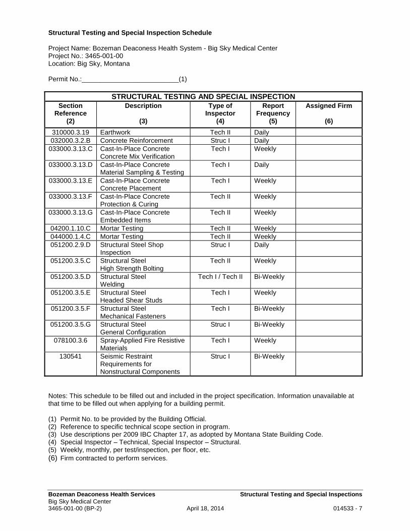
Bozeman Deaconess Health Services Structural Testing and Special Inspections Big Sky Medical Center 3465-001-00 (BP-2) April 18, 2014 014533 - 7
Structural Testing and Special Inspection Schedule Project Name: Bozeman Deaconess Health System - Big Sky Medical Center Project No.: 3465-001-00 Location: Big Sky, Montana Permit No.:__________________________(1)
STRUCTURAL TESTING AND SPECIAL INSPECTION Section
Reference (2)
Description
(3)
Type of Inspector
(4)
Report Frequency
(5)
Assigned Firm
(6)
310000.3.19 Earthwork Tech II Daily 032000.3.2.B Concrete Reinforcement Struc I Daily
033000.3.13.C Cast-In-Place Concrete Concrete Mix Verification
Tech I Weekly
033000.3.13.D Cast-In-Place Concrete Material Sampling & Testing
Tech I Daily
033000.3.13.E Cast-In-Place Concrete Concrete Placement
Tech I Weekly
033000.3.13.F Cast-In-Place Concrete Protection & Curing
Tech II Weekly
033000.3.13.G Cast-In-Place Concrete Embedded Items
Tech II Weekly
04200.1.10.C Mortar Testing Tech II Weekly 044000.1.4.C Mortar Testing Tech II Weekly 051200.2.9.D Structural Steel Shop
Inspection Struc I Daily
051200.3.5.C Structural Steel High Strength Bolting
Tech II Weekly
051200.3.5.D Structural Steel Welding
Tech I / Tech II Bi-Weekly
051200.3.5.E Structural Steel Headed Shear Studs
Tech I Weekly
051200.3.5.F Structural Steel Mechanical Fasteners
Tech I Bi-Weekly
051200.3.5.G Structural Steel General Configuration
Struc I Bi-Weekly
078100.3.6 Spray-Applied Fire Resistive Materials
Tech I Weekly
130541 Seismic Restraint Requirements for Nonstructural Components
Struc I Bi-Weekly
Notes: This schedule to be filled out and included in the project specification. Information unavailable at that time to be filled out when applying for a building permit. (1) Permit No. to be provided by the Building Official. (2) Reference to specific technical scope section in program. (3) Use descriptions per 2009 IBC Chapter 17, as adopted by Montana State Building Code. (4) Special Inspector – Technical, Special Inspector – Structural. (5) Weekly, monthly, per test/inspection, per floor, etc. (6) Firm contracted to perform services.
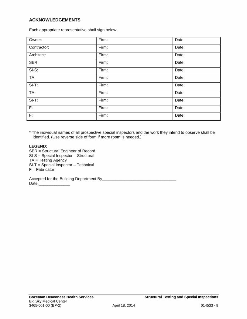
Bozeman Deaconess Health Services Structural Testing and Special Inspections Big Sky Medical Center 3465-001-00 (BP-2) April 18, 2014 014533 - 8
ACKNOWLEDGEMENTS Each appropriate representative shall sign below: Owner: Firm: Date:
Contractor: Firm: Date:
Architect: Firm: Date:
SER: Firm: Date:
SI-S: Firm: Date:
TA: Firm: Date:
SI-T: Firm: Date:
TA: Firm: Date:
SI-T: Firm: Date:
F: Firm: Date:
F: Firm: Date:
* The individual names of all prospective special inspectors and the work they intend to observe shall be
identified. (Use reverse side of form if more room is needed.) LEGEND: SER = Structural Engineer of Record SI-S = Special Inspector – Structural TA = Testing Agency SI-T = Special Inspector – Technical F = Fabricator. Accepted for the Building Department By_________________________________ Date.______________
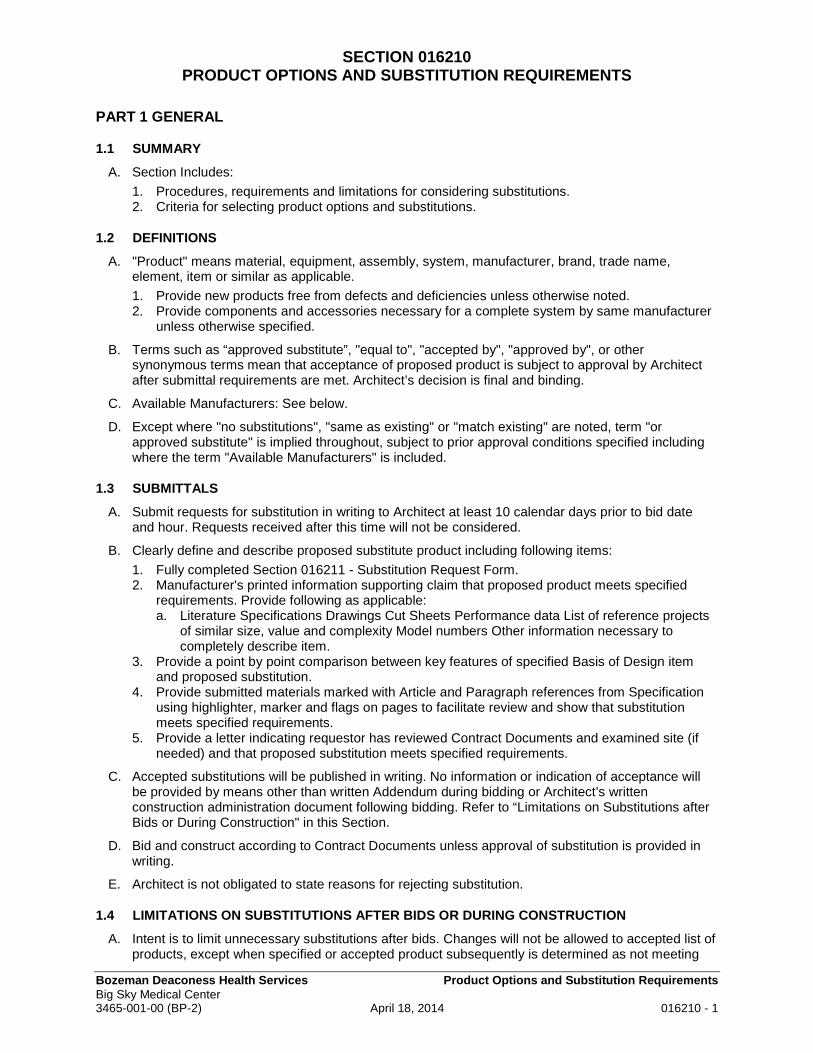
Bozeman Deaconess Health Services Product Options and Substitution Requirements Big Sky Medical Center 3465-001-00 (BP-2) April 18, 2014 016210 - 1
SECTION 016210 PRODUCT OPTIONS AND SUBSTITUTION REQUIREMENTS
PART 1 GENERAL
1.1 SUMMARY
A. Section Includes:
1. Procedures, requirements and limitations for considering substitutions. 2. Criteria for selecting product options and substitutions.
1.2 DEFINITIONS
A. "Product" means material, equipment, assembly, system, manufacturer, brand, trade name, element, item or similar as applicable.
1. Provide new products free from defects and deficiencies unless otherwise noted. 2. Provide components and accessories necessary for a complete system by same manufacturer
unless otherwise specified.
B. Terms such as “approved substitute”, "equal to", "accepted by", "approved by", or other synonymous terms mean that acceptance of proposed product is subject to approval by Architect after submittal requirements are met. Architect’s decision is final and binding.
C. Available Manufacturers: See below.
D. Except where "no substitutions", "same as existing" or "match existing" are noted, term "or approved substitute" is implied throughout, subject to prior approval conditions specified including where the term "Available Manufacturers" is included.
1.3 SUBMITTALS
A. Submit requests for substitution in writing to Architect at least 10 calendar days prior to bid date and hour. Requests received after this time will not be considered.
B. Clearly define and describe proposed substitute product including following items:
1. Fully completed Section 016211 - Substitution Request Form. 2. Manufacturer's printed information supporting claim that proposed product meets specified
requirements. Provide following as applicable: a. Literature Specifications Drawings Cut Sheets Performance data List of reference projects
of similar size, value and complexity Model numbers Other information necessary to completely describe item.
3. Provide a point by point comparison between key features of specified Basis of Design item and proposed substitution.
4. Provide submitted materials marked with Article and Paragraph references from Specification using highlighter, marker and flags on pages to facilitate review and show that substitution meets specified requirements.
5. Provide a letter indicating requestor has reviewed Contract Documents and examined site (if needed) and that proposed substitution meets specified requirements.
C. Accepted substitutions will be published in writing. No information or indication of acceptance will be provided by means other than written Addendum during bidding or Architect’s written construction administration document following bidding. Refer to “Limitations on Substitutions after Bids or During Construction" in this Section.
D. Bid and construct according to Contract Documents unless approval of substitution is provided in writing.
E. Architect is not obligated to state reasons for rejecting substitution.
1.4 LIMITATIONS ON SUBSTITUTIONS AFTER BIDS OR DURING CONSTRUCTION
A. Intent is to limit unnecessary substitutions after bids. Changes will not be allowed to accepted list of products, except when specified or accepted product subsequently is determined as not meeting

Bozeman Deaconess Health Services Product Options and Substitution Requirements Big Sky Medical Center 3465-001-00 (BP-2) April 18, 2014 016210 - 2
requirements of Contract Documents or product becomes unavailable, and then only under following conditions:
1. Orders were placed in timely manner as required after list of materials is accepted. No excuse or proposed substitution will be considered for products due to unavailability unless proof is submitted that firm orders were placed in a timely manner.
2. Reason for unavailability is beyond control of Contractor: prolonged strikes or lockouts which will delay Project to an extent unacceptable to Owner, bankruptcy, discontinuance of a product, delays or Acts of God or other similar reasons.
3. Request for substitution is submitted in writing within 10 days after date Contractor becomes aware product does not comply with specifications or has become unavailable, accompanied by supporting evidence.
4. No extra cost to Owner. 5. Substitution does not compromise design intent or quality required. 6. Substitute product is acceptable to Owner and Architect. 7. Requested substitution offers Owner a substantial advantage in cost, time, energy
conservation, or other considerations, after deducting additional responsibilities Owner must assume. Owner's additional responsibilities may include compensation to Architect for redesign and evaluation services, increased cost of other construction by Owner, and similar considerations.
8. Requested substitution does not require revisions to Contract Documents. 9. Requested substitution is consistent with the Contract Documents and will produce intended
and indicated results. 10. Substitution request is fully documented and properly submitted. 11. Requested substitution will not adversely affect Contractor's Construction Schedule. 12. Requested substitution has received necessary approvals of authorities having jurisdiction. 13. Requested substitution is compatible with other portions of Work. 14. Requested substitution has been coordinated with other portions of Work. 15. Requested substitution provides specified warranty. 16. If requested substitution involves more than one trade, requested substitution has been
coordinated with other portions of the Work, is uniform and consistent, is compatible with other products, and is acceptable to installers involved.
PART 2 MATERIALS
2.1 PRODUCTS
A. Architect and Owner reserve right to accept or reject proposed product. Should a proposed product be unable to meet requirements to satisfaction of Architect, product shall not be used. No additional compensation will be allowed for required Work resulting from use of product accepted by Addendum.
B. Use only one brand, manufacturer, source or type for like products unless otherwise approved or specified. Contractor is obligated to do so unless otherwise approved in writing.
C. Provide pricing based on products listed in Contract Documents. Contract award is based on use of specified products or substitutions approved prior to bidding or pricing.
1. By execution of Contract, Contractor agrees and understands Work will be accomplished with products specified or accepted by substitution.
D. Basis of Design Products:
1. Reference to "Basis of Design" and a named specific product or manufacturer is intended to establish criteria for use of that product and manufacturer based on that products published information whether or not those criteria are explicitly stated in Specifications.
2. Criteria may establish higher performance requirement than specified reference or performance standards. Such reference is intended to establish minimum level of quality, standard of design, function, appearance, type, strength, durability, construction, efficiency, sound level, finish, appearance, availability, service and similar characteristics determined necessary for Project.
3. Specification criteria including basis of design products are considered as a whole.

Bozeman Deaconess Health Services Product Options and Substitution Requirements Big Sky Medical Center 3465-001-00 (BP-2) April 18, 2014 016210 - 3
4. Other products or manufacturers listed meet features, performance, appearance and other criteria established by that product or manufacturer even if product must be customized to meet those criteria.
5. When other products are listed in a Section those products may be used if they meet entire specification criteria including criteria implied by product listed as basis of design. Meeting some requirements but not meeting criteria established by basis of design product does not qualify as meeting specified requirements.
6. Products or manufacturers accepted for substitution will be acceptable provided they fully comply with requirements and match basic and essential criteria of product used for basis of specification or design, including level of fabrication quality, as determined by Architect.
E. Reference Standards for Products:
1. When references to Federal Specification, ASTM Standard, American National Standards Institute (ANSI) or similar association standards are listed for product quality, provide an acceptable affidavit certifying that proposed substitution for this Project meets with same standard.
2. Submit supporting test data to substantiate compliance.
F. Substitute products shall:
1. Be available in same range of colors, textures, dimensions, gauges, types, and finishes as specified product.
2. Be equal to specified item in strength, durability, efficiency, serviceability, ease and cost of maintenance.
3. Be compatible with building design. 4. Not necessitate design modifications. 5. Not impose additional work or require changes in work of Prime Contractor, or other
Subcontractor, vendor, or materials supplier. 6. Not add cost to Owner. 7. Be similar in essential fabrication features.
G. Contractor, supplier or manufacturer providing accepted substitute product shall bear cost of required modifications to spaces, services, utilities and other features as result of accepting substitute products, including but not limited to:
1. Larger capacity mechanical or electrical service, devices or utilities resulting from acceptance of product for bidding purposes.
2. Modification to pipes, conduits, ducts, and controls for conveying, distributing, and controlling those services or utilities.
3. Modification to insulation, wrappings, coatings, or other integral features of lines or items conveying those lines.
H. Timely Placement of Product Orders: Place product orders in a timely manner, within ten days after acceptance of submitted list of materials.
2.2 LABELS, NAMEPLATES AND TRADEMARKS
A. Provide permanent nameplate on each item of service-connected or power-operated equipment. Locate nameplate on easily accessible surface.
1. Nameplate shall indicate manufacturer, model number, serial number, capacity, speed, electrical characteristics and similar essential operating data.
B. UL fire rating labels and other labels which must be visible after installation shall be located on inconspicuous surfaces.
1. Other labels and trademarks shall be located on concealed surfaces or shall be removable without damaging surfaces.
2. Do not permanently attach or imprint labels or trademarks on surfaces which will be exposed to view in occupied spaces.
C. Do not paint, deface or conceal required nameplates or labels.

Bozeman Deaconess Health Services Product Options and Substitution Requirements Big Sky Medical Center 3465-001-00 (BP-2) April 18, 2014 016210 - 4
PART 3 EXECUTION (Not Used)
END OF SECTION

Bozeman Deaconess Health Services Substitution Request Form Big Sky Medical Center 3465-001-00 (BP-2) April 18, 2014 016211 - 1
SECTION 016211 SUBSTITUTION REQUEST FORM
To: HGA Architects and Engineers, LLC
420 5th Street North, Suite 100 Minneapolis, MN 55401 Attention: Karin Johnson
Project: Bozeman Deaconess Health Services Big Sky Medical Center HGA Comm. No.: 3465-001-00 Date Received: Specification Section Number and paragraph: Drawing and details affected: Proposed Substitution:
Manufacturer:
Product (model, pattern, etc.): WHY IS SUBSTITUTION BEING SUBMITTED? (Select one of the following):
Pre-Bid Substitution (Prior Approval) Bid Date: Specified product is not available. Explain. Cost savings to Owner. Indicate comparative cost analysis. Other: Explain.
EFFECTS OF PROPOSED SUBSTITUTION: Answer the following questions and attach explanations.
Does substitution affect dimensions indicated on Drawings? NO YES, explain:
Does substitution affect Work of other Sections?
NO YES, explain:
Does substitution require modifications to design, changes to Drawings, or revisions to specifications to be incorporated into the Project?
NO YES, explain:
Attach list of at least 3 projects where proposed substitution has been used within past 12 months; include name, address, and telephone number of Owner and Architect.
CONTRACTOR'S / BIDDER'S REPRESENTATION Undersigned accepts responsibility for coordination of proposed substitution and accepts all additional costs resulting from the incorporation of proposed substitution into the Project per Section 016210. SUBMITTED BY: For Architect's use: _________________________________________________ Accepted Not Accepted No Action Required _________________________________________________ Submission: Incomplete Too Late Fax No: __________________________________________ Reviewed by/date: Comments: Subcontractor's signature and date: Contractor's signature and date:

Bozeman Deaconess Health Services Anchorage and Sleeving Big Sky Medical Center 3465-001-00 (BP-2) April 18, 2014 017324 - 1
SECTION 017324 ANCHORAGE AND SLEEVING
PART 1 - GENERAL
1.1 SUMMARY
A. Work Included:
1. General Procedural Requirements. 2. Installation of proper anchorage devices to securely fasten hang, mount, anchor, and support
all work. 3. Rough-in and installation of Equipment.
B. Related Sections
1. Section 017329 - Cutting and Patching.
1.2 TESTING
A. Under supervision of an independent testing laboratory paid by for by the Owner, 5 percent of anchors shall be field loaded above anticipated loads to insure their adequacy.
1. Drilled-in expansion anchors, which have the same hole size as the bolt size, such as "Kwik-Bolt" or "Wej-It" or "Thunderstud" by Universal Fastenings will be permitted provided: a. There is no spalling around the holes, b. The holes are neatly drilled and approved test reports indicate adequate shear and pullout
strength with ample safety factor.
PART 2 - PRODUCTS
2.1 TYPES OF ANCHORAGE AND SLEEVING DEVICES
A. New Materials: As specified in individual Sections, or as herein specified.
B. Existing Materials: Match existing products and work for anchoring and sleeving unless otherwise indicated.
PART 3 - EXECUTION
3.1 INSPECTION
A. Examine substrate and conditions under which anchorage and sleeving work is to be performed. Do not proceed with work until unsatisfactory conditions have been corrected.
3.2 INSTALLATION
A. Methods and devices, as well as location, may be subject to Owner Representative's approval and shall not impair, violate or alter structure, water integrity or aesthetic value of the Work. Sleeve existing pipes indicated.
B. In general, provide bolts and shields for anchorage to solid materials, toggle bolts into hollow construction or through bolts and washers where necessary, unless otherwise shown or specified.
C. Provide sleeves for all pipes, ducts and similar features that pass through walls, slabs, concrete joists, beams or girders, concrete columns or concrete bridging, whether specifically indicated or not.
D. Provide adequate backing for all fastenings and supports to prevent deflection or undue stresses. For concrete, anchorage devices shall generally be cast in, not drilled in later, unless otherwise specified in individual section of work or approved by the Engineer of Record.
Bozeman Deaconess Health Services Anchorage and Sleeving Big Sky Medical Center 3465-001-00 (BP-2) April 18, 2014 017324 - 2
3.3 ANCHORS
A. Furnish and install proper anchorage devices to securely fasten, hang, mount, anchor, and support work substantially.
B. Wood plugs into solid materials, toggle bolting to lath and plaster, or bolting into shields at hollow units will not be acceptable.
C. Shot and Drilled Anchors: At concrete, shot or drilled-in anchor devices will be permitted where casting in may be difficult to coordinate, provided they will not damage the concrete or cause any spalling around the anchor.
D. Shot anchors will not be permitted in bottoms of joists, in post-tensioned slabs where cable location is unknown, in slabs 4 inches or less in thickness, nor where spalling may result.
E. Any shot anchors at concrete joists shall be at the side of the joist, above centerline, located to avoid reinforcing steel. Verify shot anchors at composite decking with the Owner's Representative.
3.4 SLEEVES
A. Sleeves shall be of new material, cut square, reamed. Sheet metal sleeves may be used only where specifically approved.
1. At all concrete penetrations, sleeves shall be uncoated steel or galvanized pipe, not less than Schedule 40, or at unrated assemblies, PVC pipe is acceptable.
2. At exposed or concealed masonry walls, sleeves shall be the same as for concrete penetrations.
B. Unless otherwise called for, sleeves passing through walls, slabs, beams, bridging, columns, shall be 1/2 inch greater in inside diameter than external diameter of pipe passing through sleeves, or the insulation diameter.
1. Pipe insulation shall be continuous through the sleeves.
C. Unless otherwise called for, sleeves through walls shall extend full thickness of wall and be cut flush with finished surface; sleeves through exterior building walls, above or below grade, shall extend full thickness of wall and be cut flush with finished surfaces; sleeves through floor slabs for exposed piping shall extend not less than 1/2 inch above finished floor.
D. Sleeve Spacing: Where sleeves occur in rows or clusters, a minimum of 4 inches of concrete shall be left between sleeves and if the normal spacing of reinforcing bars cannot be maintained, or are interrupted because of sleeve size or cluster location, extra reinforcing shall be provided by the Contractor as directed by the Owner's Representative. In no case shall sleeves impair the structural capability of the Work.
E. Sealing of Sleeves: As pipe, conduit or other feature is installed through a sleeve, it shall be wedged to keep in the center of the sleeve, with wedges held 1" back from end of sleeve. Pipe, conduit or other features through walls or other vertical surfaces, shall be caulked at the top in all cases, and at the bottom where exposed in a finished space.
3.5 EQUIPMENT LAYOUTS, ROUGH-IN AND INSTALLATION
A. Unless specifically noted, equipment shall be installed in accordance with the manufacturer's recommendations and instructions.
B. Full layout data and rough-in data is to be provided by the Contractor or subcontractor supplying the equipment, to others requiring the data, in sufficient time to facilitate proper and accurate rough-in.
1. For existing equipment of the Owner, the Contractor must examine the equipment and determine the rough-in data. For equipment to be purchased by the Owner, the Owner will arrange to have the data furnished to the Contractor.
2. If rough-in details are not available at the time service systems are being installed, the final rough in shall be postponed until the data is available. At all times prior to roughing-in for equipment by Owner, consult with the Owner to verify the status of rough-in data.
C. Floor Sleeves: For waste and other services passing through the floor, if rough-in data is available, it is the intent that the rough-in sleeves generally, shall be installed prior to pouring the floors.

Bozeman Deaconess Health Services Anchorage and Sleeving Big Sky Medical Center 3465-001-00 (BP-2) April 18, 2014 017324 - 3
1. With the permission of the Owner's Representative, core drilling for other holes (even if data is available) may be done to facilitate job progress or to more accurately locate the holes, with such core drilling done without additional reimbursement.
2. If layout information for rough-in sleeving for equipment provided under the construction Contract is not available at the time sleeving through the floor must be accomplished, core drilling later shall be employed, at no additional reimbursement.
D. Core Drilled Holes: At core drilled holes, the hole shall be drilled approximately one inch larger than the outside diameter of the insulation, where insulated. When the pipe is installed, hold down centering wedges one inch minimum below the floor line. The opening shall be sealed.
END OF SECTION

Bozeman Deaconess Health Services Closeout Procedures Big Sky Medical Center 3465-001-00 (BP-2) April 18, 2014 017700 - 1
SECTION 017700 CLOSEOUT PROCEDURES
PART 1 GENERAL
1.1 SUMMARY
A. Section Includes:
1. Closeout procedures. 2. Systems and equipment testing. 3. Instructions to Owner. 4. Cleanup.
B. Related Sections:
1. Section 013100 – Project Management and Coordination. 2. Section 013216 – Construction Progress Schedule. 3. Section 015100 – Temporary Utilities. 4. Section 015200 – Construction Facilities. 5. Section 017800 – Closeout Submittals.
1.2 SUBSTANTIAL COMPLETION AND OWNER OCCUPANCY
A. Owner has urgent need to occupy Project to commence its intended use.
B. Plan an efficient, orderly and coordinated completion process including organizing, scheduling and coordinating the following:
1. Work of contractor's own forces. 2. Work of subcontractors. 3. Establish firm commitments for on-time completion 4. Owner's needs for accommodations and time to occupy project during closeout per schedule of
Substantial Completion and final completion specified in Section 013216.
C. After Substantial Completion expedite completion of remaining work in an organized, efficient manner that maintains quality standards. Perform such work according to following requirements:
1. Scheduled work in advance with Owner. 2. Perform Work in occupied spaces when space is not in use, such as after hours in
administrative areas or public spaces when public use hours are over for the day, unless otherwise approved by the Owner.
3. When necessary, use overtime to accomplish work not able to be completed during normal work hours at no extra cost to the Owner.
4. Perform Work in occupied areas in a manner and at such time as will not significantly interfere with, hamper or inconvenience Owner's program or functions.
1.3 PROJECT CLOSEOUT
A. Insurance: Refer to General Conditions.
1. Upon completion of work and written acceptance by Owner, provide a Certificate of Insurance indicating specified Completed Operations insurance will be provided a minimum of one year after Owner's acceptance of entire Project.
2. Specified Property Insurance shall be maintained until final acceptance by Owner of entire Project.
B. Supplemental Agreements: Resolve supplemental agreements prior to final payment, including adjustment of allowances.
C. Consent of Surety: Refer to General Conditions –If Payment and Performance Bonds have been indicated to be required, obtain consent of surety prior to reduction in retained percentage and prior to final payment.
D. Broken Glass: Repair.
E. Guarantees - Warranties: Refer to General Conditions for general guarantee requirements.

Bozeman Deaconess Health Services Closeout Procedures Big Sky Medical Center 3465-001-00 (BP-2) April 18, 2014 017700 - 2
1. In addition to general guarantee, provide written guarantees specified in technical sections of Specifications per Section 017800.
F. Test Reports and Certificates: Refer to Section 017800.
G. Retention of Records: Retain records required by law and good business practice.
H. Record Set of Drawings:
1. Refer to General Conditions and Section 017800. 2. Deliver record set to Architect upon Final Completion of Project. 3. Review set with Architect to clarify or explain changes that may be necessary.
I. Temporary Utilities:
1. Refer to Section 015100. 2. Remove temporary facilities and utilities as job progress permits. 3. Read meters at times specified for transfer of services cost from Contractor to Owner for
light/power.
J. Sanitary Facilities:
1. Refer to Section 015200. 2. Remove temporary fixtures and restore rooms as specified.
K. Temporary Facilities:
1. Remove as work progresses and facilities are no longer needed at time acceptable to Architect. 2. Prior to final payment, remove temporary sheds, offices, fences (including perimeter fence),
barricades, surplus materials, debris and other material or items not part of Project.
L. Extra Materials: Refer to Section 017800.
M. Construction Cores and Keys:
1. At time of Substantial Completion, just prior to occupancy, replace construction cores and install permanent cores in locks.
2. Thereafter, access to spaces will be provided by the Owner.
N. Identification of Equipment:
1. Prior to Substantial Completion, provide identification tags or plates, or other identification means, as specified under Technical Sections of Specifications, such as at valves, panelboards and similar items.
2. Apply directions on plates for circuit data and similar information.
1.4 SYSTEMS AND EQUIPMENT TESTING
A. Test equipment and systems to demonstrate each system and piece of equipment is installed and operating properly.
B. Provide a written record of tests and results per Section 017800.
C. After operation and testing of systems, instruct Owner's representatives with Architect's representative present.
1.5 INSTRUCTIONS TO OWNER
A. Provide instructions before final payment is made. Submit evidence that instruction/maintenance manuals were delivered to and were acceptable to Owner.
B. Requirements herein supplement specific requirements provided under individual specification sections.
C. Collect information and data so complete manuals are provided in sufficient time to permit review prior to time for final payment. Refer also to Section 017800.
D. Provide qualified representatives of Contractor or subcontractors to give explanations and instructions.
E. Provide instruction manuals per Section 017800 to be used and reviewed during instructions.

Bozeman Deaconess Health Services Closeout Procedures Big Sky Medical Center 3465-001-00 (BP-2) April 18, 2014 017700 - 3
F. Thoroughly and properly instruct the Owner in use, operation, care and maintenance of Project, especially various systems and equipment installed under Contract. Give instructions methodically and carefully. Cover various phases of work and in sufficient detail so Owner fully understands entire Project.
G. Orient and familiarize designated Owner Representatives with locations, methods, materials, uses and operation of systems and equipment, as well as specialized materials installed under Contract.
H. Instruct and demonstrate to the Owner regarding full use, sequence or function and similar information to fully acquaint Owner in proper use, care and control of equipment, systems and devices installed under Contract.
I. Precautionary Measures and Dangers of Misuse.
1. Specifically explain precautions and dangers of misuse. 2. Establish specific and agreed upon periods of time with the Owner, adequate to thoroughly
present pertinent information. 3. Owner will record length of time and number of days spent on these instructions.
J. Refer to Section 013100 for additional information and data for maintenance manual such as coordination drawings.
K. Information Not Required:
1. Normal and routine cleaning of normal floor and wall finishes. 2. Maintenance of light fixtures. 3. Cleaning of radiation covers. 4. Hardware maintenance. 5. Other similar housekeeping matters.
1.6 CLEANUP
A. Refer to General Conditions for cleaning requirements during construction.
B. Clean materials and equipment. Remove (haul away) debris, cartons, crates, surplus materials.
C. Maintain work neat and orderly.
D. Definitions
1. Thorough Cleaning: a. Thorough cleaning required unless otherwise specified. b. Remove dust, dirt, debris, laitance, grease, oil, stains, discolorations, droppings, markings,
and other soil or foreign matter or substance. c. Remove labels except labels specifically designated to remain as part of listed, rated or
labeled item. d. Use appropriate methods such as sweeping, scrubbing, mopping, washing, dusting
vacuuming so surface is completely clean and streak free. 2. Broom Clean: Remove visible dirt or dust from surface with a new, high quality, clean broom by
thoroughly and properly sweeping or brooming so no dust or dirt is visible on surface.
E. Perform general "final" cleaning prior to inspection for Substantial Completion and occupancy. Plan, organize and coordinate cleaning to avoid working in spaces once cleaned. Coordinate timely cleaning with Architect especially for cleaning of glass.
F. Clean entire Project including, but not limited to:
1. Cleaning required under each Section. 2. Remove accumulated dust, dirt and debris. 3. Materials, equipment or other items. 4. Glass - both sides, interior and exterior, and mirrors. 5. Infection Control Area Cleanup:
a. Vacuum clean above ceiling, pipes, and ventilation ducts after construction is completed. b. Check ventilation filters for breaks or leaks. c. Use damp mopping for dust control. d. Minimize traffic between construction area and patient control areas. e. Obtain Owner approval of cleaned area before proceeding.

Bozeman Deaconess Health Services Closeout Procedures Big Sky Medical Center 3465-001-00 (BP-2) April 18, 2014 017700 - 4
G. Electrical Subcontractor Cleaning: Includes but is not limited to:
1. Normally occupied areas, service areas, passages and corridors and similar spaces. 2. Interiors of cabinets, panelboards and other equipment. 3. Other work under contract needing cleaning.
H. Mechanical Subcontractor Cleaning: Includes but is not limited to:
1. Remove filters used during construction and install permanent new filters. 2. Ductwork. 3. Fixtures and fittings. 4. Insides of convectors. 5. Unit heaters or similar units 6. Radiation. 7. Piping and equipment in equipment rooms 8. Other work under contract needing cleaning.
I. "Broom Clean" is allowed in following areas:
1. Tunnels, shafts, air shafts and air plenums not constructed of ductwork 2. Similar areas. 3. Floors in equipment rooms (including rooms such as electrical equipment rooms)
a. Except also wash floors and apply final coat of sealer if specified.
J. Floors (including concrete) must be free of stains and discoloration
K. Hardware: Adjust and polish as needed
L. Perform other cleaning as required to turn the Project over to the Owner in new, well maintained condition, ready for full use and occupancy.
M. Clean areas made dirty by work done after Substantial Completion so building is clean as specified prior to Final Completion.
1.7 FINAL ACCEPTANCE AND FINAL PAYMENT
A. Final payment will not be made until final acceptance inspection, completion of punch list items and final sign-off by Owner and Architect.
PART 2 PRODUCTS Not Used.
PART 3 EXECUTION Not Used.
END OF SECTION
Bozeman Deaconess Health Services Closeout Submittals Big Sky Medical Center 3465-001-00 (BP-2) April 18, 2014 017800 - 1
SECTION 017800 CLOSEOUT SUBMITTALS
PART 1 GENERAL
1.1 SUMMARY
A. Section Includes:
1. Closeout submittals. 2. Warranties and guarantees. 3. Test reports and certificates. 4. Extra materials. 5. Maintenance manuals. 6. Record drawings and specifications.
B. Related Sections:
1. Section 013300 - Submittal Procedures. 2. Section 017700 - Closeout Procedures.
1.2 WARRANTIES AND GUARANTEES
A. Provide written guarantees specified in technical sections of Specifications.
B. Where guarantee terms are included in Specifications or a specific guarantee is referenced, submit guarantee in specified form.
C. Submit guarantees prior to final payment.
D. Submit a checklist of required guarantees, by section numbers.
1.3 TEST REPORTS AND CERTIFICATES
A. Provide test reports and certificates required in technical sections prior to final payment.
B. Provide a written record of systems and equipment testing and results.
C. Provide a check list of required reports and certificates, by Specifications sections.
1.4 EXTRA MATERIALS
A. Prior to final completion, deliver extra materials specified in various technical sections.
B. Do not allow materials to "collect" in various parts of Project. Deliver to Owner together.
C. Obtain receipt for specified extra materials. Without such evidence of delivery, no credit will be given for fulfilling specified requirements.
D. Provide a checklist of specified extra materials.
1.5 OPERATING INSTRUCTIONS AND MAINTENANCE MANUALS
A. Coordinate submittals from Section 013300 that will be needed to fulfill following requirements.
B. Provide operating instruction data and maintenance manuals in accordance with Section 017700 -Closeout Procedures.
C. Organize information by classes or types of equipment and systems as follows:
1. Manuals shall consist of neatly edited and typed instruction manuals (in hard cover, indexed, loose-leaf notebook) to explain use, function and control of equipment, materials and systems. Printed information shall include: a. Warranties and guarantees. b. Common errors made, which will "abuse" equipment or system c. Use, function and control of equipment and systems d. Clean installation data and pamphlets (not to be left at equipment but included in manuals)

Bozeman Deaconess Health Services Closeout Submittals Big Sky Medical Center 3465-001-00 (BP-2) April 18, 2014 017800 - 2
e. Instructions and explanations. f. Cleaning instructions. g. Wiring and piping diagrams. h. Various types of maintenance procedures. i. Lubrication data and schedules. j. Maintenance materials to be used. k. Maintenance information. l. Maintenance instructions with frequency. m. Other maintenance information. n. Adjustment and repair data. o. Parts list with numbers and recommended parts for Owner's stock. p. Names, addresses, and telephone numbers parts distributor. q. Names, addresses, and telephone numbers of appropriate service organizations for
various items and equipment. 2. Manuals shall include systems and equipment as specified, but not limited to following
information: a. Heating plant b. Heating and ventilating equipment c. Fan units d. Air conditioning e. Controls for mechanical systems f. Alarm systems g. Electrical distribution systems h. Operating equipment of general construction i. Mechanical and electrical work j. Elevators k. Kitchen equipment l. Operable partitions m. Power operated doors n. Other similar systems and equipment.
1.6 RECORD SET OF DRAWINGS AND SPECIFICATIONS
A. Provide record set of Drawings and Specifications to Architect at completion of Contract.
1. Refer to General Conditions for general requirements. 2. Refer to Section 013300 - Submittal Procedures, for posted (updated) job site contract
documents.
B. During construction, maintain clean set of Drawings and Specifications for sole purpose of recording changes to Contract.
C. Mark record set methodically as work progresses, clearly and neatly, in color.
Bozeman Deaconess Health Services Closeout Submittals Big Sky Medical Center 3465-001-00 (BP-2) April 18, 2014 017800 - 3
D. Include information cut and pasted into appropriate location of documents to reference change, adjustment, or clarification. Type of information to be recorded on record set includes but is not limited to:
1. Addendum items sent during bidding 2. Changes, deviations or revisions made, except minor or non-critical dimensions, including
those made by Change Order or Supplementary Instructions. 3. Accepted submittals including shop drawings, product data and samples. 4. Omissions, including work omitted by accepted alternates. 5. Dimensioned locations of major or main utility lines, such as main conduit runs, piping mains
and similar work. 6. Locations of control valves. 7. Additions to the work. 8. Changes in significant details. 9. Changed footing or other elevations. 10. Locations of electrical home run boxes, including circuit numbers and panel designations for
each box. 11. Coordination drawings. 12. Changes in locations of panelboards, outlets, drains, piping, openings, dampers and similar
features. 13. Other similar data.
PART 2 PRODUCTS Not Used.
PART 3 EXECUTION Not Used.
END OF SECTION

Bozeman Deaconess Health Services Concrete Forming Big Sky Medical Center 3465-001-00 (BP-2) April 18, 2014 031100 - 1
SECTION 031100 CONCRETE FORMING
PART 1 GENERAL
1.1 SUMMARY
A. Section Includes:
1. Responsibility for design, engineering, construction, maintenance, completeness, safety, and adequacy of removable formwork.
2. Formwork required for cast-in-place concrete, with shoring, bracing and anchorage. 3. Items, materials, operations and methods including labor, equipment and incidentals. 4. Coordinate installation of items furnished under other sections.
1.2 REFERENCES
A. ACI 117 - Specification for Tolerances for Concrete Construction and Materials.
B. ACI 301 - Specifications for Structural Concrete for Buildings.
C. ACI 318 - Building Code Requirements for Structural Concrete.
D. ACI 347 - Guide to Formwork for Concrete.
E. PS1 - Construction and Industrial Plywood.
F. AISC Code of Standard Practice for Steel Buildings and Bridges
1.3 QUALITY ASSURANCE
A. Applicable Standards: ACI 347 "Guide to Formwork for Concrete" and ACI 301 "Specifications for Structural Concrete for Buildings".
B. Allowable Tolerances: Design, construct and maintain formwork to insure completed work within tolerance limits specified in ACI 301 and ACI 117, unless more stringent tolerances are given in this specification, with stipulation that no tolerances specified for horizontal or vertical building lines or footings should be construed to permit encroachment beyond legal boundaries.
PART 2 PRODUCTS
2.1 FORM-FACING MATERIALS
A. General: Provide formwork units with sufficient thickness and stiffness to resist plastic concrete loads without detrimental deformation.
B. Forms for Exposed Smooth-Formed Finish Concrete: Construct formwork for exposed concrete surfaces with form-facing panels that will provide continuous, true, and smooth exposed concrete surfaces. Furnish in largest practicable sizes to minimize number of joints and to conform to joint system shown on Drawings. Form exposed corners with 3/4 inch by 3/4 inch chamfer strips, mitered at changes in direction.
1. Plywood, metal, or other approved panel materials 2. Exterior-grade plywood panels, suitable for concrete forms, complying with DOC PS 1, and as
follows: a. High-density overlay, Class 1 or better. b. Medium-density overlay, Class 1 or better; mill-release agent treated and edge sealed. c. Structural 1, B-B, or better; mill oiled and edge sealed. d. B-B (Concrete Form), Class 1 or better, mill oiled and edge sealed.
C. Forms for Unexposed Rough-Formed Finish Concrete: Form concrete surfaces which will be unexposed in finished structure with plywood, lumber, metal or other acceptable material. Provide lumber dressed on at least 2 edges and one side for tight fit.
Bozeman Deaconess Health Services Concrete Forming Big Sky Medical Center 3465-001-00 (BP-2) April 18, 2014 031100 - 2
D. Backing for Forms: Structurally sound lumber or metal frame, solid, straight and free of defects that may impair its strength.
E. Void Forms: Biodegradable paper surface, treated for moisture resistance, structurally sufficient to support weight of plastic concrete and other superimposed loads.
2.2 ACCESSORIES FOR REMOVABLE FORMS
A. Form Ties: Factory-fabricated, adjustable-length, removable or snap-off metal or glass-fiber-reinforced plastic form ties, designed to resist lateral pressure of fresh concrete on forms without form deflection, and to prevent spalling concrete surfaces upon removal.
1. Provide ties so that portion remaining within concrete after removal of exterior parts is at least one inch from outer concrete surface.
2. Spreader cones on ties shall not be larger than one inch in diameter. 3. At exposed finish concrete provide form ties with plastic cones and plastic setback plugs, color
as selected, with equal spacing in horizontal and vertical line.
B. Chamfer and Reveal or Recess Strips: Wood, metal, PVC, or rubber strips. Triangular chamfer strips shall be 3/4 inch by 3/4 inch. Round chamfer strips shall have 3/4 inch radius. Size reveal or recess strips as noted. Wood strips shall have planed faces.
C. Form-Release Agent: Commercially formulated form-release agent that will not bond with, stain, nor adversely affect concrete surfaces, and will not impair subsequent treatment of surfaces requiring bond or adhesion, nor impede wetting of surfaces to be cured with water or curing compounds.
1. Formulate form-release agent with rust inhibitor for steel form-facing materials.
PART 3 EXECUTION
3.1 DESIGN
A. Removable Forms: Design for vertical and lateral loads and pressures, including static, dynamic and construction loads, as outlined in the ACI Standard "Guide to Formwork for Concrete" (ACI 347). Contractor is solely responsible for the design, engineering, construction, maintenance, completeness, safety, and adequacy of all removable formwork.
B. Tolerances: Design formwork so concrete members and structures are of size, shape, alignment, elevation and position indicated, within allowable tolerances of ACI 117 or those specified.
C. Surface Irregularities: Limit concrete surface irregularities, designated by ACI 347R as abrupt or gradual, as follows:
1. Class C, 1/2 inch – General conditions. 2. Class D, 1 inch – Foundations permanently concealed to view.
D. Openings: Design formwork with temporary openings at locations as required for inspections and to permit removal of extraneous materials before placing concrete.
E. Removal: Design forms for safety in removal and with proper sequence without damage to concrete. Forms should be easily removed without hammering or prying against concrete surfaces.
F. Foundation: Design satisfactory foundations for formwork supported on ground to carry loads imposed during construction, without appreciable settlement.
G. Joints: Design with minimum number of joints and with joints sufficiently tight to prevent leakage of grout or cement paste.
3.2 ERECTION OF REMOVABLE FORMS
A. Verify lines, levels, measurements, elevation and center locations before proceeding with formwork.
B. Construct forms of materials selected to obtain required finishes.
C. Provide crush plates or wrecking plates where stripping may damage cast concrete surfaces.
D. Provide top forms for inclined surfaces steeper than 1.5 horizontal to 1 vertical or where slope is too steep to place concrete with bottom forms only.

Bozeman Deaconess Health Services Concrete Forming Big Sky Medical Center 3465-001-00 (BP-2) April 18, 2014 031100 - 3
E. Kerf wood inserts used for forming keyways, recesses, and similar features to prevent swelling and assure ease of removal.
F. Do not use rust-stained steel form-facing material.
G. Locate temporary openings in forms as inconspicuous as possible, consistent with project requirements. Brace closures and set tightly to forms to prevent loss of concrete mortar.
H. Provide permanent openings in forms where shown or required to accommodate other work, including Mechanical and Electrical Work.
I. Erect, support, brace and maintain formwork and false-work to safely support vertical, lateral, and asymmetrical loads and forces until they can be supported by in- place concrete structures.
J. For exposed concrete, drill forms to suit approved ties and spacing and to prevent leakage of mortar around tie holes. Do not splinter forms by driving ties through improperly prepared holes.
K. For exposed concrete, do not use metal cover plates to patch holes or defects in forms.
L. Chamfer exterior corners and edges of permanently exposed concrete.
M. At intersecting planes provide sharp, clean corners without visible edges or offsets and back joints with extra studs or girts to maintain true, square intersections.
N. At changes in plane, form molding shapes, recesses and projections with smooth-finish materials, and install in forms with sealed joints to prevent displacement.
O. Thoroughly clean forms and adjacent surfaces to receive concrete. Remove chips, wood, sawdust, dirt or other debris before concrete is placed. During cold weather be sure that ice and snow has been removed.
P. Retighten forms, if necessary, before and immediately after concrete is placed to eliminate mortar leaks and to maintain proper alignment. Carefully inspect false-work and formwork during and after concrete placement operations to determine abnormal deflections or signs of possible failure and make necessary adjustments to produce work of required dimensions.
Q. Do not displace or damage vapor retarder.
3.3 EMBEDDED ITEMS
A. Accurately place and securely support anchorage devices and other embedded items required for adjoining work that is attached to, or supported by, cast-in-place concrete. Use setting drawings, templates, diagrams, instructions and directions furnished with items to be embedded.
B. Install anchor rods, accurately located, to elevations required and complying with tolerances in Section 7.5 of AISC’s “Code of Standard Practice for Steel Buildings and Bridges.”
3.4 APPLICATION OF FORM RELEASE AGENT
A. Apply form release agent on formwork in accordance with manufacturer's instructions. Do not allow excess form release agent to accumulate in forms or come into contact with surfaces which will be bonded to fresh concrete. Apply prior to placing reinforcing steel, anchoring devices, and embedded items.
B. Do not apply form release agent where concrete surfaces are scheduled to receive special finishes or applied coverings which may be affected by agent. Soak contact surfaces of untreated forms with clean water. Keep surfaces wet prior to placing concrete.
C. Do not apply form release agent where wood graining characteristics are required on finished concrete surfaces. Leave formwork dry.
3.5 FORM REMOVAL AND REUSE
A. Do not remove forms and bracing until concrete has gained sufficient strength to carry its own weight, construction live loads, and lateral loads which are liable to be imposed upon them without damage, overstress, or excessive deflection.
Bozeman Deaconess Health Services Concrete Forming Big Sky Medical Center 3465-001-00 (BP-2) April 18, 2014 031100 - 4
1. Remove load-supporting forms only when concrete has attained 75 percent of required 28 day compressive strength.
B. Forms not directly supporting weight of concrete may be removed after cumulatively curing at not less than 50 degrees F for 24 hours after placing concrete. Concrete has to be hard enough to not be damaged by form-removal operations and curing and protection operations need to be maintained.
C. Loosen forms carefully. Do not wedge pry bars, hammers, or tools against concrete surfaces. Repair or replace, as directed, all damaged work.
D. Clean and repair surfaces of forms to be reused. Store removed forms used for exposed concrete in manner that surfaces to be in contact with fresh concrete will not be damaged. Split, frayed, delaminated, or otherwise damaged form-facing material will not be acceptable for reuse on exposed surfaces.
E. When forms are reused, clean surfaces, remove fins and laitance, and tighten to close joints. Align and secure joints to avoid offsets. Do not use patched forms for exposed concrete surfaces unless approved by Architect.
F. Earth retaining walls: Do not backfill against walls until all work is in place which braces the top and bottom of walls against lateral displacement and until concrete has attained its design strength.
END OF SECTION

Bozeman Deaconess Health Services Concrete Accessories Big Sky Medical Center 3465-001-00 (BP-2) April 18, 2014 031500 - 1
SECTION 031500 CONCRETE ACCESSORIES
PART 1 GENERAL
1.1 SUMMARY
A. Section Includes:
1. Concrete accessories and related materials for cast-in-place concrete. 2. Coordinate work in this section with requirements of Sections 031100 and 033000.
1.2 SUBMITTALS
A. Submit in accordance with Section 013300.
B. Product Data: Manufacturer's specifications and technical data including performance, construction and fabrication information.
1. Submit certificates of compatibility for all products with other products of this section or other sections where products will be in contact.
C. Shop Drawings: Indicate dimensions, description of materials and finishes, general construction, specific modifications, component connections, anchorage methods, hardware, and installation procedures, including specific requirements indicated.
PART 2 PRODUCTS
2.1 UNDERSLAB VAPOR BARRIERS
A. (UVB-3) Under-Slab Vapor Barrier: ASTM E 1745, Class A. Permeance of less than 0.01 perms before and after mandatory conditioning tests per ASTM E 1745, Sections 7.1.1 – 7.1.5.
1. Minimum Thickness ACI 302 15-mil 2. Maximum Water Vapor Permeance ASTM E 154 0.01 perms 3. Minimum Tensile Strength ASTM E 154 45 lbf/in. 4. Puncture Resistance ASTM D 1709 2200 grams 5. Available Products: Subject to compliance with requirements, products that may be
incorporated into the Work include, but are not limited to, the following: a. Epro Services: Ecoshield E15 b. Raven Industries: VaporBlock VB15. c. Reef Industries: Griffolyn 15 Mil Green. d. Stego Industries: Stego Wrap 15 mil. e. Viper: VaporCheck 16 mil. f. W.R. Meadows: Perminator 15 mil.
B. Accessories:
1. Seam Tape at Underslab Vapor Barrier: a. Manufacturer’s recommended high density polyethylene tape with pressure sensitive
adhesive. Minimum width 4 inches. b. Permeance less than 0.3 perms per ASTM F 1249 or ASTM E 96.
2. Pipe Boots for Underslab Vapor Barrier: a. Construct pipe boots from vapor barrier material and pressure sensitive tape per
manufacturer's instructions.
2.2 EXPANSION JOINT FILLERS
A. Expansion Joint Fillers (Non-Sealed): Resilient non-extruding premolded bituminous impregnated fiberboard complying with ASTM D 1751.
1. Acceptable Manufacturers: a. Brock-White. b. North Central Construction Supply.

Bozeman Deaconess Health Services Concrete Accessories Big Sky Medical Center 3465-001-00 (BP-2) April 18, 2014 031500 - 2
c. W.R. Meadows.
B. Expansion Joint Fillers (Backing for Sealant): Flexible, compressible, closed-cell polyethylene foam, not less than 10 psi compression deflection.
2.3 INSERTS
A. Dovetail Anchor Slots: Fabricate from not less than 22 gauge galvanized steel with one inch wide back by one inch deep with 5/8 inch throat. Nail holes 4 inch o.c.
1. Provide complete with fibrous, waterproof slot sealer or removable foam slot filler. 2. Acceptable Manufacturers and Products:
a. Gateway Beehive Slot. b. Heckman Building Products No. 100.
B. Wedge Type Shelf Angle Inserts: Malleable iron castings with wedge shaped holding faces to receive 5/8 inch askew head bolt.
1. Do not use inserts complete with askew head bolts, flat washers, nuts and horseshoe shims. 2. Acceptable Manufacturers:
a. Dayton Superior. b. Gateway Building Products.
C. Expansion Sleeves: Where reinforcing extends from concrete mass to support adjacent slab, with provisions for expansion required, provide metal sleeve at each bar to permit movement.
1. Provide at stoops and elsewhere as indicated.
D. Reglets: Form reglets in concrete exposed to weather (for membranes, flashing and similar items), with removable forms (inserts). Form reglets, wedge-shaped to preserve sharp edges of concrete with twice material thickness, but not less than 3/8 inch.
1. Temporarily fill or cover face opening of reglet to prevent intrusion of concrete or debris. 2. Do not use metal reglets, except where specifically approved. 3. For concealed reglets use 24-gauge galvanized metal flashing reglet #307. 4. Acceptable Manufacturers:
a. Hohmann-Barnard. b. Gateway Building Products. c. Heckman Building Products.
E. Dowel Caps: Plastic material of size recommended for rod diameter.
F. Stair Nosings: Spectra Type WP4C by Wooster Products.
G. Refer to Section 055000 for embeds and other fabricated items for insertion into concrete.
2.4 CURING AND SEALING MATERIALS
A. Manufacturers: Subject to compliance with the requirements, manufacturers offering products that may be incorporated into the Work include, but are not limited to, the those listed below.
B. Evaporation Retarder: Waterborne, monomolecular film forming, manufactured for application to fresh concrete.
1. Finishing Aid Concentrate; Burke Group, LLC (The). 2. Spray-Film; ChemMasters. 3. Aquafilm; Conspec Marketing & Manufacturing Co., Inc. 4. Sure Film; Dayton Superior Corporation. 5. Eucobar; Euclid Chemical Co. 6. E-Con; L&M Construction Chemicals, Inc. 7. Confilm; Master Builders, Inc.
C. Moisture-Retaining Cover: ASTM C 171, polyethylene film or white burlap-polyethylene sheet.
D. Water: Potable.
E. (CS-2) Clear, Non-yellowing, Waterborne, Membrane-Forming Curing and Sealing Compound: ASTM C 1315, Type 1, Class A, minimum 30 percent total solids. Comply with ACI 301, only for floors to remain bare or where surface treatments are compatible. Apply in accordance with

Bozeman Deaconess Health Services Concrete Accessories Big Sky Medical Center 3465-001-00 (BP-2) April 18, 2014 031500 - 3
manufacturer's recommendations. For floors to remain bare such as mechanical or utility rooms thoroughly clean surface and apply additional roller application just prior to project completion.
1. Klear-Kote Cure-Sealer-Hardener, 30 percent solids; Burke Group, LLC (The). 2. Polyseal WB; ChemMasters. 3. Lumiseal WB Plus; L&M Construction Chemicals, Inc. 4. Vocomp-30; W. R. Meadows, Inc. 5. Master Kure; Master Builders 6. Dress & Seal #30; L&M Construction Chemicals, Inc. 7. Super Rez-Seal; Euclid Chemical Co.
PART 3 EXECUTION
3.1 INSTALLATION
A. Install concrete accessories and related materials as specified in Section 031100 - Concrete Formwork, Section 032000 – Concrete Reinforcement, and Section 033000 - Cast-in-Place Concrete.
END OF SECTION

Bozeman Deaconess Health Services Concrete Reinforcing Big Sky Medical Center 3465-001-00 (BP-2) April 18, 2014 032000 - 1
SECTION 032000 CONCRETE REINFORCING
PART 1 GENERAL
1.1 SUMMARY
A. Section Includes:
1. Reinforcing bars for cast-in-place concrete. 2. Welded steel wire fabric where noted in the drawings. 3. Ties and supports for reinforcement.
1.2 REFERENCES
A. ACI 117 - Specification for Tolerances for Concrete Construction and Materials.
B. ACI 315 - Standards on Details and Detailing of Concrete Reinforcement.
C. ACI 318 - Building Code Requirements for Structural Concrete.
D. AWS D1.4 - Structural Welding Code Reinforcing Steel.
E. CRSI - Manual of Standard Practice.
F. CRSI - Placing Reinforcing Bars.
1.3 ACTION SUBMITTALS
A. Product Data: For each type of manufactured material and product indicated
B. Shop Drawings:
1. Shop Drawings: Submit in accordance with Section 013300 and ACI 315, “Details and Detailing of Concrete Reinforcement.”
2. Include placing drawings that detail fabrication, bending, and placement. Include bar sizes, lengths, material, grade, bar schedules, stirrup spacing, bent bar diagrams, bar arrangement, splices and laps, mechanical connections, tie spacing and hoop spacing.
3. Show locations, type and quantities of bolsters, spacers, chairs, support bars and other accessories.
4. Show concrete cover dimension from face of form to reinforcing bars.
1.4 INFORMATIONAL SUBMITTALS
A. Welding Certificates
B. Material Certificates: For each of the following, signed by manufacturers:
1. Steel reinforcement and accessories
1.5 QUALITY ASSURANCE
A. Installer Qualifications: Perform concrete reinforcing work in accordance with Concrete Reinforcing Steel Institute's recommended practices.
B. Testing Agency Qualifications: An independent testing agency, acceptable to authorities having jurisdiction, qualified according to ASTM C 1077 and ASTM E 329 to conduct the testing indicated, as documented according to ASTM E 548.
1. Allow specified inspector to observe reinforcing steel in place prior to pouring of concrete for each section.
2. Do not pour concrete until permission to proceed with placement of concrete has been granted by specified inspector.
3. Notify specified inspector sufficiently in advance of scheduled time for pouring of concrete to allow observation to be made and corrections or adjustments completed, where required.
C. Welding: Qualify procedures and personnel according to AWS D1.4, "Structural Welding Code--Reinforcing Steel."

Bozeman Deaconess Health Services Concrete Reinforcing Big Sky Medical Center 3465-001-00 (BP-2) April 18, 2014 032000 - 2
1.6 DELIVERY, STORAGE AND HANDLING
A. Materials shall be new, free of rust, loose scale or other coating that would reduce or destroy bond.
B. Deliver reinforcement bundled, tagged and marked. Tags to indicate bar size, lengths, and other information corresponding to markings shown on placement diagrams.
C. Deliver, store and handle reinforcement to prevent bending, damage and accumulation of dirt or excessive rust.
D. Avoid damaging coatings on steel reinforcement.
PART 2 PRODUCTS
2.1 STEEL REINFORCEMENT
A. Reinforcing Bars: ASTM A 615, Grade 60, deformed.
B. Low-Alloy-Steel Reinforcing Bars: Reinforcing Steel to be Welded or Special Ductile Reinforcement: ASTM A 706, deformed.
C. Epoxy Coated Reinforcing Bars: ASTM A 775 or ASTM A 934, epoxy coated, with less than 2 percent damaged coating in each 12-inch bar length.
D. Plain-Steel Welded Wire Reinforcement: ASTM A 185, fabricated from as-drawn ASTM A 82 plain-steel wire into flat sheets, rolls are not permitted.
2.2 REINFORCEMENT ACCESSORIES
A. Wire Bar Type Supports: Bolsters, chairs, spacers, and other devices for spacing, supporting, and fastening reinforcing bars and welded wire reinforcement in place. Manufacture according to CRSI’s “Manual of Standard Practice”.
B. Supports: For slabs-on-grade with steel reinforcement use supports with sand plates, precast concrete chairs, or horizontal runners where base materials will not support chair legs.
C. Plastic-Tipped or Stainless Steel Legs: For concrete surfaces exposed to view or weather where legs of wire bar supports contact forms, use CRSI Class 1 plastic-protected or CRSI Class 2 stainless-steel bar supports. Hot dip galvanized support accessories may be used against formed surfaces not exposed to view or to weather.
D. Precast Concrete Chairs: Use over membrane waterproofing or under-slab vapor retarder/barrier to prevent penetration of membrane or barrier.
E. Flat Plate Dowels: Saw cut from ASTM A 36 hot rolled plate.
1. PNA Construction Technologies: Diamond Dowel 2. Greenstreak Group, Inc.: Speed Plate
F. Epoxy-Coated Supports and Tie Wire: For epoxy-coated reinforcement, use epoxy coated or other dielectric-polymer-coated wire bar supports.
G. Epoxy-Coated Smooth Bar Dowels: ASTM A 615, Grade 60, plain round bars, ASTM A 775 epoxy coated.
H. Headed Shear Stud Reinforcement: Shear stud reinforcement consisting of single-headed studs attached to a steel base rail by welding or double-headed studs mechanically crimped into a steel shape meeting the requirements of ICC Evaluation Service Acceptance Criteria AC395.
1. Stud reinforcement dimensions and materials shall comply with ASTM A 1044.
2.3 FABRICATION
A. Fabricate steel reinforcement in accordance with ACI 315, CRSI’s “Manual of Standard Practice” and accepted shop drawings.
B. Do not re-bend or straighten steel reinforcement except where specifically accepted.
Bozeman Deaconess Health Services Concrete Reinforcing Big Sky Medical Center 3465-001-00 (BP-2) April 18, 2014 032000 - 3
PART 3 EXECUTION
3.1 INSTALLATION
A. Under-floor Vapor Retarders/Barriers: When chairing reinforcement on top of under-floor vapor retarders, use only concrete brick type reinforcing bar supports, or provide 6 in x 6 in protective pads of asphaltic hardboard or other material recommended by the manufacturer. Do not displace or damage vapor retarder.
B. After installation of reinforcement but before pouring concrete, check for damage to under-floor vapor retarder/barrier. Repair any damage and reseal under-floor vapor retarder before placing concrete in accordance with Section 033000.
C. Clean steel reinforcement to remove loose rust and mill scale, earth, ice and other foreign materials which will reduce or destroy bond with concrete.
D. Install concrete reinforcement in accordance with reviewed shop drawings and CRSI recommended practices.
E. Accurately position, support, and secure steel reinforcement against displacement by formwork, construction, or concrete placement operations.
F. Locate and support steel reinforcing by metal bolsters, spacers, chairs and hangers to maintain specified concrete cover. Securely tie bars and supports together with 16 gauge wire to hold steel reinforcement accurately in position during concrete placement operations. Set wire ties so that twisted ends are directed away from concrete surfaces.
G. Installing bars into wet concrete is prohibited.
H. Provide bar supports in sufficient number and heavy enough to carry steel they support. Place no bar more than 2 inches beyond last leg of continuous bar support. Do not use bar supports to support runways for concrete buggies, or similar loads.
I. Steel reinforcement partially embedded in concrete shall not be field bent, except as indicated or permitted by Structural Engineer.
J. For walls reinforced on both faces, provide spreader bars and chairs to surfaces of forms on each side at spacing not to exceed 8 feet in either direction. For walls with single layer of reinforcing, provide chairs each side at spacing not to exceed 8 feet in either direction.
K. Splice bars only where shown or noted. Comply with requirements of ACI 318 for minimum lap of bars and stagger, unless noted otherwise..
L. Install welded wire fabric in longest practicable lengths on bar supports spaced to minimize sagging. Offset end laps in adjacent sheets to prevent continuous laps in either direction. Lap edges and ends of adjoining sheets at least two mesh spacing. Lace overlaps with wire. Locate fabric as indicated on Drawings.
M. Install diamond plate dowels in concrete slab-on-grade joints where shown. Install diamond plate dowels per manufacturer’s written instructions.
N. Exposed reinforcing steel after concrete has been placed, indicating steel is not properly located, will be sufficient cause for rejection, removal and replacement of concrete section.
O. Tack welding of reinforcing steel is prohibited. Reinforcement damaged by arc strikes or welding shall be replaced.
3.2 FIELD QUALITY CONTROL
A. Testing and Inspection: Owner will engage qualified special inspectors in accordance with Section 014533.
1. Qualifications: The minimum category of special inspector required to perform services outlined below are noted by qualifications in parentheses. The definitions of the categories of special inspector are included in Section 014533.
B. Inspect all reinforcing steel in all cast-in-place concrete, excluding slabs on grade, footings without transverse reinforcement, and topping slabs. (Structural I)
Bozeman Deaconess Health Services Concrete Reinforcing Big Sky Medical Center 3465-001-00 (BP-2) April 18, 2014 032000 - 4
1. Verify size and grade of reinforcing steel. 2. Verify reinforcing bars are free of dirt, excessive rust and damage. 3. Verify reinforcing bars are adequately tied, chaired and supported to prevent displacement
during concrete placement. 4. Verify proper clear distances between bars and to surfaces of concrete. 5. Verify reinforcing bar size and placement. 6. Verify bar laps for proper length and stagger and bar bends for minimum diameter, slope and
length.
C. Welding of Reinforcing Bars: Visually inspect 100% of all reinforcing bar welds as the welding is performed, per AWS D1.4. Verify proper joint preparation is provided and proper electrodes are used and properly stored and dried. (Technical II)
END OF SECTION

Bozeman Deaconess Health Services Cast-In-Place Concrete Big Sky Medical Center 3465-001-00 (BP-2) April 18, 2014 033000 - 1
SECTION 033000 CAST-IN-PLACE CONCRETE
PART 1 GENERAL
1.1 SUMMARY
A. Section Includes:
1. Cast-in-place concrete, cement, aggregates, water and admixtures. 2. Proportioning, mixing, conveying, placing, finishing, curing, and testing of cast-in-place
concrete. 3. Installation of concrete accessories for cast-in-place concrete. 4. Coordinate installation of embedded items furnished and installed under other sections.
1.2 REFERENCES
A. ACI 117 - Specifications for Tolerances for Concrete Construction and Materials
B. ACI 214 - Recommended Practice for Evaluation of Strength Test Results of Concrete.
C. ACI 301 - Specifications for Structural Concrete for Buildings.
D. ACI 304 - Guide for Measuring, Mixing, Transporting and Placing Concrete.
E. ACI 305 - Hot Weather Concreting.
F. ACI 306 - Cold Weather Concreting.
G. ACI 309 - Guide for Consolidation of Concrete.
H. ACI 318 - Building Code Requirements for Structural Concrete.
1.3 DEFINITIONS
A. Floor Flatness Number, FF, measures floor curvature or flatness per ASTM E 1155.
B. Floor Levelness Number, FL, measures floor inclination from a horizontal plane per ASTM E 1155.
C. Floor Levelness, (FL), tolerances only apply to non-sloping slabs-on-grade and suspended slabs shored at time of testing. Floor Levelness tolerances shall not apply to slabs placed on unshored form surfaces, shored surfaces after removal of shores, or pitched slab surfaces per ACI 302.
D. Overall FF/FL numbers represent minimum values acceptable for all combined local floor test sections representing the specified floor finish area per ACI 302.
E. Local FF/FL test areas shall be defined as follows per ACI 302.
1. Areas bounded by construction or control joints for slabs-on-grade. 2. Areas bounded by columns and/or wall lines for elevated structural slabs. 3. No less than one-half bay size.
F. Cementitious Materials: Portland cement alone or in combination with one or more of the following: blended hydraulic cement, fly ash and other pozzolans, ground granulated blast-furnace slag, and silica fume; subject to compliance with requirements.
1.4 ACTION SUBMITTALS
A. Product Data: For each type of product indicated.
B. Submit mix design for each type and strength of concrete. Proportion designs in accordance with "Proportioning on the Basis of Field Experience and/or Trial Mixtures" of ACI 318.
C. Each mix design shall contain the following information:
1. Mix number (which will correspond to mix ticket on trucks delivered to site) and location of concrete on project.
2. Applicable mix specifications including: a. Design strength.
Bozeman Deaconess Health Services Cast-In-Place Concrete Big Sky Medical Center 3465-001-00 (BP-2) April 18, 2014 033000 - 2
b. Slump. c. Air content. d. Unit weight.
3. Mix ingredients including quantities, ASTM designations, and sources for: a. Cementitious materials including fly ash, silica fume, and GGBFS. b. Aggregates. c. Water.
1) Indicate amounts of mix water to be withheld for later addition at Project Site. d. Admixtures (including manufacturer).
4. Test results: a. Compressive strength results of trial batches or historical test data. b. Statistical computations showing required average strength of mix. c. Aggregate property results for exterior horizontal concrete in accordance with Article 2.1.C
of this Section. d. Combined aggregate gradation as indicated for slab-on-grade mixes. e. Unit weight. f. Slump. g. Water/cementitious ratio of mix. h. Air content.
5. Material Certificates: Signed by manufacturers certifying that materials comply with Project requirements.
D. Include alternate mix designs when characteristics of materials, project conditions, weather, test results, or other circumstances warrant adjustments.
E. Construction Joint Layout: Indicate proposed construction joints required to construct the structure.
1. Proposed construction joint and saw cut contraction joints locations for slab on grade. 2. Location of joints is subject to approval of the Architect/Engineer.
1.5 INFORMATIONAL SUBMITTALS
A. Placing, Finishing, and Curing Procedures: Detailed description of methods, materials, and equipment used to comply with requirements.
B. Cold-Weather and Hot-Weather Procedures: Detailed description of methods, materials, and equipment to be used to comply with requirements.
C. Flooring Coordination Plan (FCP): The General Contractor (GC) shall develop a Flooring Coordination Plan (FCP) prior to placement of any on-grade or elevated floor slabs. The GC shall conduct a pre-installation meeting to coordinate with all trades as it relates to the installation of the floor slab. The plan shall be signed by all trade representatives confirming agreement. Submittal is for information only and will not be approved or rejected. The FCP shall include the following items:
1. Review ACI302.2 “Guide for Concrete Slabs that Receive Moisture-Sensitive Flooring.” 2. Concrete mix design. 3. Discussion of delay of drying time due to re-wetting of floor slabs per on-site field conditions. 4. Type and degree of concrete finish with respect to flooring adhesive and material. 5. Curing process. 6. Application of topical finishes such as slab curing compounds and sealers, if requested by the
Contractor, with certificates of compatibility. 7. Moisture/pH testing procedure and frequency. 8. Trade representative work schedules.
1.6 QUALITY ASSURANCE
A. Manufacturer Qualifications: Use plant mixed concrete mixed in stationary mixers.
1. Truck mixed concrete is allowed provided procedures in ASTM C94 are followed and documented.
2. Mix and deliver concrete in accordance with ASTM C94.
B. Installer Qualifications: Perform concrete work in accordance with ACI 318, unless specified otherwise. Installation work shall be supervised by a ACI-certified Flatwork Technician.

Bozeman Deaconess Health Services Cast-In-Place Concrete Big Sky Medical Center 3465-001-00 (BP-2) April 18, 2014 033000 - 3
C. Testing Agency Qualifications: An independent testing agency, acceptable to authorities having jurisdiction, qualified according to ASTM C1077 and ASTM E329 to conduct the testing indicated, as documented according to ASTM E548.
D. Source Limitations: Obtain each type or class of cementitious material of the same brand from the same manufacturer's plant, obtain aggregate from single source, and obtain admixtures from single source from single manufacturer.
E. Pre-Construction Conference: Conduct conference at Project site to comply with requirements of Section 014533.
1. Before submitting design mixtures, review concrete design mixture and examine procedures for ensuring quality of concrete materials. Require representatives of each entity directly concerned with cast-in-place concrete to attend, including the following: a. Contractor's superintendent. b. Independent testing agency responsible for concrete design mixtures. c. Ready-mix concrete manufacturer. d. Concrete subcontractor. e. Special concrete finish subcontractor.
2. Review special inspection and testing and inspecting agency procedures for field quality control, concrete finishes and finishing, cold- and hot-weather concreting procedures, curing procedures, construction contraction and isolation joints, and joint-filler strips, semirigid joint fillers, vapor-retarder installation, anchor rod and anchorage device installation tolerances, steel reinforcement installation, floor and slab flatness and levelness measurement, concrete repair procedures, and concrete protection.
PART 2 PRODUCTS
2.1 CONCRETE MATERIALS
A. Portland Cement: ASTM C150, Type I or Type I/II, corresponding to cement on which selection of concrete proportions was based. Use same brand for each required type of concrete.
B. Normal Weight Concrete Aggregates: (Excluding exterior horizontal concrete) ASTM C33, uniformly graded. Do not use aggregates containing soluble salts or other substances which can cause stains on exposed surfaces. Use aggregates from one source of supply corresponding to that on which selection of concrete proportions was based.
C. Aggregates for Exterior Horizontal Concrete: Limits of deleterious substances and physical property requirements of fine and coarse aggregates shall comply with ASTM C33, Class 5S and following additional requirements for exterior horizontal concrete:
1. Amount of deleterious substances in fine aggregate shall not exceed following limits: Item Weight Percent of Total Sample
Maximum Clay lumps and friable particles 3.0 Material finer than No. 200 sieve 3.0 Coal, lignite and shale 0.5
2. Aggregates shall be free of materials with deleterious reactivity to alkali in cement. When fine
aggregate is tested for potential reactivity by chemical method in accordance with ASTM C289, relationship between quantity Rc (reduction in alkalinity) and quantity Sc (dissolved silica) shall indicate that material is innocuous.
3. Coarse aggregate for exterior horizontal concrete (other than toppings less than 2 inch in thickness) shall be size number 67 (3/4 inch to No. 4) and shall be 100 percent crushed quarry rock composed of basalt, quartzite, granite, limestone or dolomite. For toppings less than 2 inch in thickness use size number 8.
4. When subjected to 5 cycles of soundness test using magnesium sulfate in accordance with ASTM C88, aggregate shall have loss of not more than 18 percent for coarse aggregate and 15 percent for fine aggregate.
5. Coarse aggregate shall have maximum abrasion loss of 50 percent by weight when tested in accordance with ASTM C131, Grading B.

Bozeman Deaconess Health Services Cast-In-Place Concrete Big Sky Medical Center 3465-001-00 (BP-2) April 18, 2014 033000 - 4
6. Requirements of ASTM C33, Table 3, as to amount of material in coarse aggregate having specific gravity lighter than 2.4 shall include iron oxide.
D. Aggregate Gradation: Conform to ASTM C 33 and as specified herein.
1. Well Graded Aggregate: Provide in concrete mixes indicated with the combined coarse and fine aggregates meeting the following criteria:
Top Size Aggregate 1 ½” 1” ¾” Sieve Size % Retained on Sieve 1 ½” 0% - 8% 1” 8% - 18% 0% - 8% 0% - 6% ¾” 8% - 18% 8% - 22% 6% - 22% ½” 8% - 18% 8% - 22% 6% - 22% 3/8” 8% - 18% 8% - 22% 6% - 22% No. 4 8% - 18% 8% - 22% 6% - 22% No. 8 8% - 18% 8% - 22% 6% - 22% No. 16 8% - 18% 8% - 22% 6% - 22% No. 30 8% - 18% 8% - 22% 6% - 22% No. 50 3% - 12% 3% - 12% 3% - 12% No. 100 0% - 8% 0% - 8% 0% - 8% No. 200 0% - 5% 0% - 5% 0% - 5%
a. At least 55% by weight shall be retained on or above the #4 sieve. b. A maximum of two non-adjacent sieves between 1 inch and No. 50 may fall outside the
prescribed limits above with a minimum of 5% retained and a maximum of 22% retained on these nonconforming sieves.
E. Water: ASTM C94. Fresh, clean, potable, free from injurious amounts of oils, acids, alkalies, salts, organic materials, or other substances that may be deleterious to concrete or steel.
2.2 SUPPLEMENTARY CEMENTING MATERIALS
A. General: The following materials shall be incorporated into the Work as specified or at Contractors option within the limitations set forth.
B. Fly Ash Admixture: ASTM C618, Class C or F; Loss of Ignition (LOI) less than 1 percent. Addition of fly ash to regular weight concrete mixes to reduce amount of cement is permissible as follows:
1. When used in exposed concrete it shall be used throughout for uniform color.
C. Silica Fume: ASTM C1240, amorphous silica.
1. Degussa: Rheomac SF 100 or 110. 2. Elkem Materials: Grade 920 or EMSAC 500 S 3. W.R. Grace: Force 10,000 D or S
D. Ground Granulated Blast-Furnace Slag (GGBFS): ASTM C989, Grade 100 or Grade 120.
E. Replacement Ratio: Portland cement shall be replaced on an equal mass (not weight) basis. The material replacements shall be expressed as a percent, by mass, of the total cementitious materials content, with proportions selected for 28 day compressive strengths equal to those specified. The change in volume resulting from the substitutions shall be determined and an adjustment in both coarse and fine aggregate proportions shall be determined in order to ensure a unit volume.
F. Water-Cementitious Materials Ratio: The full mass of the total cementitious materials shall be included in the denominator for the water-cementitious materials ratio (w/c) calculation.
2.3 ADMIXTURES
A. General: Admixtures shall be certified by manufacturer not to contain more than 0.1 percent water-soluble chloride ions by mass of cementitious material and to be compatible with other admixtures and cementitious materials. Do not use admixtures containing calcium chloride or thiocyanates.
B. Manufacturers: Subject to compliance with the requirements, manufacturers offering products that may be incorporated into the Work include, but are not limited to, those listed below.
Bozeman Deaconess Health Services Cast-In-Place Concrete Big Sky Medical Center 3465-001-00 (BP-2) April 18, 2014 033000 - 5
C. Air-Entraining Admixtures (AEA): ASTM C260.
1. Euclid Chemical Company: Air-Mix. 2. General Resource Technology: Polychem AE. 3. Grace Construction Products: Daravair series or Darex series. 4. BASF: MB AE 90 or Micro Air. 5. Protex Industries: Protex AES.
D. Water Reducing Admixtures (WRA): ASTM C494, Type A.
1. Euclid Chemical Company: Eucon WR-75. 2. General Resource Technology: Polychem 1000. 3. Grace Construction Products: WRDA. 4. BASF: Pozzolith 210 or Pozzolith 322 N
E. Mid-Range Water-Reducing Admixtures (MRWRA): ASTM C494, Type A.
1. Euclid Chemical Company: Eucon A+. 2. General Resource Technology: KB-1000. 3. Grace Construction Products: Daracem-65. 4. BASF: Polyheed 997 or Polyheed FC100.
F. High-Range Water Reducing Admixture (HRWRA): ASTM C494, Type F or G.
1. Euclid Chemical Company: Eucon 37 or Plastol 5000. 2. General Resource Technology: Melchem. 3. Grace Construction Products: ADVA 100 or Daracem 100. 4. BASF: Glenium 3000 NS, 3030 NS, or 3200 HES.
G. Water Reducing and Retarding Admixture: ASTM C494, Type D.
1. Euclid Chemical Company: Eucon Retarder-75. 2. General Resource Technology: Polychem R. 3. Grace Construction Products: Daratard 17. 4. BASF: Pozzolith 80 or Pozzolith 200N.
H. Non-Corrosive, Non-Chloride Accelerator: ASTM C494, Type C or E,
1. Euclid Chemical Company: Accelguard 80. 2. General Resource Technology: Polychem Super Set. 3. Grace Construction Products: Polarset. 4. BASF: Pozzolith NC 534.
I. Viscosity Modifying Admixture: ASTM C494, Type S
1. Euclid Chemical Company: Visctrol. 2. General Resource Technology: Polychem VMA. 3. Grace Construction Products: V-MAR 3. 4. BASF: Rheomac VMA 362.
J. Prohibited Admixtures: Calcium chloride, thiocyanates or admixtures effectively containing chloride ions (more than 0.05 percent) are not permitted.
2.4 BONDING COMPOUNDS
A. Bonding Compound: ASTM C1059, Type II, non-redispersible, acrylic emulsion or styrene butadiene. Use to bond toppings to base slab.
2.5 REPAIR MATERIALS
A. Repair Underlayment: Cement-based, polymer-modified, self-leveling product that can be applied in thicknesses from 1/8 inch and that can be feathered at edges to match adjacent floor elevations.
1. Cement Binder: ASTM C 150, portland cement or hydraulic or blended hydraulic cement as defined in ASTM C 219.
2. Primer: Product of underlayment manufacturer recommended for substrate, conditions, and application.
3. Aggregate: Well-graded, washed gravel, 1/8 to 1/4 inch or coarse sand as recommended by underlayment manufacturer.

Bozeman Deaconess Health Services Cast-In-Place Concrete Big Sky Medical Center 3465-001-00 (BP-2) April 18, 2014 033000 - 6
4. Compressive Strength: Not less than 4100 psi at 28 days when tested according to ASTM C 109/C 109M.
B. Repair Overlayment: Cement-based, polymer-modified, self-leveling product that can be applied in thicknesses from 1/4 inch and that can be filled in over a scarified surface to match adjacent floor elevations.
1. Cement Binder: ASTM C 150, portland cement or hydraulic or blended hydraulic cement as defined in ASTM C 219.
2. Primer: Product of topping manufacturer recommended for substrate, conditions, and application.
3. Aggregate: Well-graded, washed gravel, 1/8 to 1/4 inch or coarse sand as recommended by topping manufacturer.
4. Compressive Strength: Not less than 5000 psi at 28 days when tested according to ASTM C 109/C 109M.
C. Polymer-Modified, Cementitious Patching Mortar: Packaged, dry mix for repair of concrete and that contains a non-redispersible latex additive as either a dry powder or a separate liquid that is added during mixing.
1. Compressive Strength: Not less than 5000 psi at 28 days when tested according to ASTM C 109/C 109M.
2.6 CONCRETE MIXING
A. Prepare design mixtures for each type and strength of concrete, proportioned on the basis of laboratory trial mixture or field test data, or both, according to ACI 211.1 and ACI 301.
B. Ready-Mixed Concrete: Measure, batch, mix, and deliver concrete according to ASTM C 94, with exceptions specified herein, and ASTM C 1116 where fibers are used, and furnish batch ticket information.
1. When air temperature is between 85 and 90 deg F, reduce mixing and delivery time from 1-1/2 hours to 75 minutes; when air temperature is above 90 deg F, reduce mixing and delivery time to 60 minutes.
C. Admixtures: Use approved admixtures according to manufacturer's written instructions.
1. Use chemical admixtures in concrete, as required, for placement, workability, durability, and controlled set time.
D. Air Content:
1. Exterior exposed concrete shall contain 6 percent entrained air with maximum tolerance of plus or minus 1.5 percent
2. Do not allow air content of hard-troweled finished floors to exceed 3 percent.
E. Concrete Slump Limits: Measured according to ASTM C 143 at point of placement.
1. 4 inches without water reducing admixtures 2. 5 inches after addition of WRA or MRWRA. 3. 7 inches after addition of HRWRA. 4. A tolerance of up to one inch above indicated maximum will be allowed for one batch in any five
consecutive batches tested. 5. If the maximum water-cement ratio is not exceeded, concrete arriving at the jobsite within 60
minutes of the initial batching that has a slump less than the maximum allowed may have water added when accepted by the project inspector.
6. Water reducing admixtures may be added to increase the slump when water cannot be added and additional slump is necessary for workability when accepted by the project inspector.
7. Truck batch tickets shall clearly indicate maximum water permissible for adding at jobsite without exceeding the specified maximum water-cementitious materials ratio.
8. Water shall not be added to the mix after any supplemental water reducing admixtures have been dosed into the mixer.
9. Water shall not be added to mix after samples are taken from batches randomly selected for testing.

Bozeman Deaconess Health Services Cast-In-Place Concrete Big Sky Medical Center 3465-001-00 (BP-2) April 18, 2014 033000 - 7
2.7 CONCRETE MIXTURES FOR BUILDING ELEMENTS
A. Footings, Foundation Walls and Piers: Proportion normal-weight concrete mixture as follows:
Item Requirements Compressive Strength at 28 days (min), f’c As indicated in Drawings Maximum water/cementitious materials ratio, w/cm 0.55 Cementitious Materials
Portland Cement, Type I or Type I/II Supplementary Cementitious Materials
80% maximum 20% minimum
Top Size Aggregate Required 3/4 inch
B. Slabs on Grade: Proportion normal-weight concrete mixture as follows:
Item Option A Option B Compressive Strength at 28 days (min), f’c 4000 psi 4000 psi Maximum water/cementitious materials ratio, w/cm 0.45 0.45 Cementitious Materials Content 540-580 lbs/yd3 500-540 lbs/yd3
Cementitious Materials Portland Cement, Type I or Type I/II Fly Ash, Class C or F
60% - 85% 15% - 40%
Top-size Aggregate 1 inch 1-1/2 inch Aggregate Gradations Well Graded Air Entraining Admixture, (AEA) None Coarseness Factor 52 - 70 Workability Factor 32 - 40 Water Reducing Admixture, (WRA), ASTM C 494, Type A
As necessary to bring slump up to maximum 5-inches within manufacturer’s limits.
High-Range Water Reducing Admixture, (HRWRA), ASTM C 494, Type F
As necessary to further increase slump for additional workability up to maximum 7-inches within manufacturer’s limits.
C. Suspended Slabs-On-Metal Deck: Proportion normal-weight concrete mixture as follows:
Item Requirements Compressive Strength at 28 days (min), f’c As indicated in Drawings Cementitious Materials Content 540 – 580 lbs/yd3 Maximum water/cementitious materials ratio, w/cm 0.45 Cementitious Materials
Portland Cement, Type I or Type I/II Fly Ash, Class C or F GGBFS
60% - 80% 20% - 30% 0% - 10%
Top Size Aggregate Required 3/4 inch Coarseness Factor 52 - 70 Workability Factor 32 - 40 Aggregate Gradation Well Graded
D. Concrete Stair Pan Fill: Proportion normal-weight concrete mixture as follows:
Item Requirements Compressive Strength at 28 days (min), f’c 3500 psi Maximum water/cementitious materials ratio, w/cm 0.55 Cementitious Materials
Portland Cement, Type I or Type I/II Supplementary Cementitious Materials
80% maximum 20% minimum
Top Size Aggregate Required 1/2 inch
Bozeman Deaconess Health Services Cast-In-Place Concrete Big Sky Medical Center 3465-001-00 (BP-2) April 18, 2014 033000 - 8
PART 3 EXECUTION
3.1 INSTALLATION OF UNDERFLOOR VAPOR BARRIERS
A. Install vapor barrier (UVB-3) directly below all new interior slabs.
1. Place vapor barrier over underfloor material specified in Division 31. 2. Do not cover vapor barrier with sand or aggregate. 3. Pour concrete slab directly over vapor barrier.
B. Examine substrates and conditions, with Installer present, for compliance with requirements for Sections in which substrates and related work are specified and other conditions affecting performance.
C. Proceed with installation only after unsatisfactory conditions have been corrected.
D. Verify that sleeves, ties, and other penetrating components which pass through surfaces to receive barrier are rigidly installed.
E. Clean substrates of substances harmful to vapor barriers, including removing projections capable of puncturing vapor barriers.
F. Place, protect, and repair vapor barrier sheets in accordance with manufacturer's instructions and ASTM E1643.
1. Unroll vapor barrier with the longest dimension parallel with the direction of the pour. 2. Lap vapor barrier over footings and seal to foundation walls. 3. Overlap joints 6 inches and seal with pressure sensitive tape. 4. Seal penetrations including pipes, conduits, and ducts with pipe boots and pressure sensitive
tape. 5. No penetration of the vapor barrier is allowed except for reinforcing steel and permanent
utilities. 6. Terminate vapor barrier at walls with sealant. 7. Repair damaged areas by cutting patches of vapor barrier, overlapping damaged area 6 inches
and taping all four sides with pressure sensitive tape.
3.2 PLACING CONCRETE
A. Place concrete in accordance with ACI 301. Consolidate concrete in accordance with ACI 309 using high frequency vibrators.
B. Clean forms, reinforcing and accessories and dampen forms immediately prior to placing concrete.
C. Schedule concrete deliveries to ensure that concrete in each load is placed within 90 minutes after mixing water is added.
D. Before placing concrete, verify that installation of formwork, reinforcement, and embedded items is complete and that required inspections have been performed.
E. Deposit concrete as near as practicable to its final position to avoid segregation due to rehandling or flowing, in layers not exceeding 18 inch in depth. Deposit concrete continuously or in layers of such thickness that no new concrete will be placed on concrete that has hardened enough to cause seams or planes of weakness.
1. Consolidate placed concrete with mechanical vibrating equipment. Use equipment and procedures for consolidating concrete recommended by ACI 309R.
2. Do not use vibrators to transport concrete inside forms. Insert and withdraw vibrators vertically at uniformly spaced locations no farther than the visible effectiveness of the vibrator. Place vibrators to rapidly penetrate placed layer and at least 6 inches into preceding layer. Do not insert vibrators into lower layers of concrete that have begun to lose plasticity. At each insertion, limit duration of vibration to time necessary to consolidate concrete and complete embedment of reinforcement and other embedded items without causing mix constituents to segregate.
3. Do not insert vibrators to bottom of slabs-on-grade with under-floor vapor barriers to avoid damaging this membrane.
Bozeman Deaconess Health Services Cast-In-Place Concrete Big Sky Medical Center 3465-001-00 (BP-2) April 18, 2014 033000 - 9
F. Deposit and consolidate concrete for floors and slabs in a continuous operation, within limits of construction joints, until placement of a panel or section is complete.
1. Consolidate concrete during placement operations so concrete is thoroughly worked around reinforcement and other embedded items and into corners.
2. Maintain reinforcement in position on chairs during concrete placement. 3. Screed slab surfaces with a straightedge and strike off to correct elevations. 4. Slope surfaces uniformly to drains where required. 5. Begin initial floating using bull floats or darbies to form a uniform and open-textured surface
plane, free of humps or hollows, before excess moisture or bleedwater appears on the surface. Do not further disturb slab surfaces before starting finishing operations
G. Do not allow concrete to fall freely more than 5 feet. Use tremies, chutes or elephant trunks where necessary.
H. Do not use concrete that has partially hardened or been contaminated by foreign materials, nor concrete that has been retempered or remixed after initial set.
I. Before depositing new concrete on or against concrete that has set at construction joints, clean, wet and apply neat cement slurry to existing surfaces. Tighten forms prior to resuming pouring.
J. Exercise care to prevent splashing of forms or reinforcing with concrete above level of concrete being placed.
K. Clean reinforcement projecting above or out of concrete immediately after completion of particular unit of pour.
L. Do not place concrete under adverse weather conditions unless adequate protection is provided. Refer to ACI 301, for weather restrictions and placing temperatures.
M. Bond concrete toppings placed over concrete slabs to base slabs using bonding compound. Install in accordance with manufacturer's instructions. Do not allow bonding compound to dry prior to pouring topping.
3.3 COLD WEATHER CONCRETING
A. Cold-Weather Placement: Comply with ACI 306.1 and as follows. Protect concrete work from physical damage or reduced strength that could be caused by frost, freezing actions, or low temperatures.
1. When air temperature has fallen to or is expected to fall below 40 deg F, uniformly heat water and aggregates before mixing to obtain a concrete mixture temperature of not less than 50 deg F and not more than 80 deg F at point of placement.
2. Do not use frozen materials or materials containing ice or snow. Do not place concrete on frozen subgrade or on subgrade containing frozen materials.
3. Do not use calcium chloride, salt, or other materials containing antifreeze agents or chemical accelerators, unless otherwise specified and approved in mix designs.
4. Ensure minimum temperatures are maintained for the duration of the curing period in accordance with ACI 306.1.
3.4 HOT WEATHER CONCRETING
A. Hot-Weather Placement: Place concrete according to recommendations in ACI 305R and as follows, when hot-weather conditions exist:
1. Cool ingredients before mixing to maintain concrete temperature below 90 deg F at time of placement. Chilled mixing water or chopped ice may be used to control temperature, provided water equivalent of ice is calculated to total amount of mixing water. Using liquid nitrogen to cool concrete is Contractor's option.
2. When temperature of steel reinforcement, embeds, subgrade, or forms is greater than 120 degrees F, fog-spray forms, steel reinforcement, embeds, and subgrade just before placing concrete. Keep subgrade moisture uniform without standing water, soft spots, or dry areas.
3. Dispatch transport trucks to avoid delays and organize work to use concrete promptly. 4. Protect concrete from wind and direct sunlight to avoid rapid drying. Apply evaporation
retarder, curing compounds, and moisture retaining covers in accordance with concrete curing and protection methods as specified.
Bozeman Deaconess Health Services Cast-In-Place Concrete Big Sky Medical Center 3465-001-00 (BP-2) April 18, 2014 033000 - 10
3.5 CONSTRUCTION, CONTRACTION AND EXPANSION JOINTS
A. Provide construction joints when stoppage of concreting operations occurs.
B. Continue reinforcing steel across construction joints unless noted or detailed otherwise.
C. Construction Joints: Install so strength and appearance of concrete are not impaired, at locations indicated or as approved by Engineer.
D. Contraction Joints in Slabs-on-Grade: Form weakened-plane contraction joints, sectioning concrete into areas as indicated. Where contraction joint spacing are not specifically shown they shall be spaced no more than 12 feet on centers for 4 inch slabs and 15 feet on center for 5 inch slabs at interior locations where joints will be exposed or under non-resilient floor covering. Interior panels shall be near-square with short: long side ratio not less than 2:3. At exterior locations spacing of contraction joints shall not exceed 10 feet on centers and short-long side ratio shall not be less than 3:4. Construct contraction joints for a depth equal to at least one-fourth of concrete thickness, as follows:
1. Sawed Joints: Form contraction joints with power saws equipped with shatterproof abrasive or diamond-rimmed blades. Sawcut joints in concrete slabs-on-grade as soon as the slab will support the weight of the saw and operator without disturbing the final finish. Saw-cutting can normally occur from 0 to 2 hours after final finishing. Cut 1/8 inch wide joints into concrete when cutting action will not tear, abrade, or otherwise damage surface and before concrete develops random contraction cracks.
2. Provide very lightly rounded edges at construction, control and expansion joints where slab joint will be exposed.
E. Isolation Joints in Slabs-on-Grade: After removing formwork, install joint-filler strips at slab junctions with vertical surfaces, such as column pedestals, foundation walls, grade beams, and other locations, as indicated.
1. Extend joint-filler strips full width and depth of joint, terminating flush with finished concrete surface, unless otherwise indicated.
2. Terminate full-width joint-filler strips not less than 1/2 inch nor more than 1 inch below finished concrete surface where joint sealants, specified in Section 079000 - Joint Protection, are indicated.
3. Install joint-filler strips in lengths as long as practicable. Where more than 1 length is required, lace or clip sections together.
F. Provide vertical construction, control, and expansion joints in walls as detailed. Pour sections alternately with minimum waiting period of 48 hours between adjacent pours. Unless noted otherwise, locate joints midway between columns. Do not locate joints within 5 feet of corner, wall intersection or column. Unless noted otherwise locate vertical contraction joints in walls at 30 feet maximum spacing.
G. Provide control joints in poured in place concrete curbs 10 feet on center maximum spacing with expansion joints not over 40 feet on center. Make control joints by cutting approximately 1/8 inch wide by one inch to 1-1/2 inch deep into exposed surfaces. Expansion joints shall be 1/2 inch wide with joint filler. At curbs adjacent to sidewalks, align joints in curb and sidewalk.
H. Unless noted or detailed otherwise provide for expansion joints in sidewalks at intervals not to exceed 40 feet on centers and where walks abut curbs, stoops, walls or other fixed objects. Expansion joints shall be 1/2 inch wide using filler materials. Provide tooled weak plane joints across sidewalks, one inch deep by 1/4 inch at 5 feet intervals, unless otherwise noted. Tool edges of joints to 1/8 inch radius.
3.6 JOINT FILLING
A. Prepare, clean, and install joint filler according to manufacturer's written instructions.
1. Defer joint filling until concrete has aged at least 6 months. Do not fill joints until construction traffic has permanently ceased.
B. Remove dirt, debris, saw cuttings, curing compounds, and sealers from joints; leave contact faces of joint clean and dry.

Bozeman Deaconess Health Services Cast-In-Place Concrete Big Sky Medical Center 3465-001-00 (BP-2) April 18, 2014 033000 - 11
C. Install semi-rigid epoxy joint filler full depth in saw-cut joints and at least 2 inches deep in formed joints. Overfill joint and trim joint filler flush with top of joint after hardening.
3.7 FINISHING FLOORS AND SLABS
A. Finish bare concrete floors (adjacent to floors with other surfacing) so concrete surface is level with other finishes, unless otherwise noted.
B. At areas to receive floor covering, grind smooth joints between slabs on grade and structural slabs and between existing and new surfaces to eliminate unevenness and to provide smooth, level surface across joints.
C. Wetting the concrete surface during finishing operations is prohibited.
D. Power floating with troweling machines equipped with normal trowel blades is prohibited.
E. Protect finished surfaces from damage. Keep free of abrasive materials.
F. In areas where water will be present (interior and exterior) place and finish slabs so areas will drain and water will not stand in puddles. Conform to slopes shown. At structural slabs, verify elevations of drains to insure drains will be at low points. Where elevations and slopes are not indicated, generally slope floors 1/8 inch per foot uniformly to drains, unless otherwise directed by Architect.
G. Finish and measure surface so gap at any point between concrete surface and an unleveled, freestanding, 10-foot-long straightedge resting on 2 high spots and placed anywhere on the surface does not exceed 3/16-inch.
H. Apply slab finish to Floor Profile Number tolerances listed unless specifically noted otherwise on Drawings, according to ASTM E 1155 “Standard Test Method for Determining FF Floor Flatness and FL Floor Levelness Numbers” for randomly trafficked floor surfaces.
1. Refer to ACI 302, Chapter 8 and Table 8.15.3, for recommended typical procedures to attain specified Floor Profile Numbers.
I. General Finishing Requirements: Comply with ACI 302.1R recommendations for screeding, restraightening, and finishing operations for concrete surfaces as appropriate to attain slab finish specified.
1. Utilize wet-screed guides, dry-screed guides, and/or edge forms for initial strike-off set with optical or laser instruments as appropriate to attain specified Floor Profile Number. Check elevation after initial strike-off and repeat as necessary.
2. Smooth and restraighten surface using 8 to 10 foot wide bull float, darby, or modified highway straightedge. a. Apply in two directions at 45 degree angle to strip for Overall Floor Flatness, FF30 or
greater. 3. Wait until bleed water sheen has disappeared and concrete can sustain finishing operations
employed without digging in or disrupting the levelness of the surface. 4. Float surface with one or more passes using a power float (float shoe blades or pans) or by
hand floating if area is small or inaccessible to power driven floats. Restraighten, cut down high spots, and fill low spots. Repeat float passes and restraightening until surface is left with a uniform, smooth, granular texture.
5. Uniformly slope surfaces to drains.
J. (CONC FIN-1) Hard Trowel Finish:
1. Follow General Finishing Requirements for initial procedures. 2. Restraighten surface if required following paste-generating float passes using 10-foot wide
highway straightedge. Apply in two directions at 45 degree angle to strip. Use supplementary material to fill low spots.
3. Consolidate concrete surface, uniform in texture and appearance, with three or more passes using power trowel. Hand trowel areas inaccessible by power trowel.
4. Grind smooth any surface defects that would telegraph through applied floor covering system.
K. (CONC FIN-2) Non-Slip Broom Finish:
1. Follow General Finishing Requirements for initial procedures.

Bozeman Deaconess Health Services Cast-In-Place Concrete Big Sky Medical Center 3465-001-00 (BP-2) April 18, 2014 033000 - 12
2. While still plastic, slightly roughen concrete surface by brooming with fiber-bristle broom perpendicular to main traffic route. Coordinate required final finish with Architect before application.
L. (CONC FIN-4) Light Trowel Finish:
1. Follow General Finishing Requirements for initial procedures. 2. Restraighten surface if required following paste-generating float passes using 10-foot wide
highway straightedge. Apply in two directions at 45 degree angle to strip. Use supplementary material to fill low spots.
3. Consolidate concrete surface, uniform in texture and appearance, with one to three passes using power trowel. Hand trowel areas inaccessible by power trowel.
4. After final trowel, concrete finish shall have a light texture. Avoid burnished finish. Coordinate finish with flooring subsurface requirements.
5. Grind smooth any surface defects that would telegraph through applied floor covering system.
M. (CONC FIN–5) Trowel and Fine Broom Finish:
1. Follow General Finishing Requirements for initial procedures. 2. Consolidate concrete surface, with one pass using a power trowel. 3. Slightly scarify surface with soft bristled broom while concrete is still plastic.
N. (CONC FIN-6) Float Finish:
1. Follow General Finishing Requirements for initial procedures.
O. (CONC FIN-10) Broom Finish:
1. Surfaces of concrete mixes with silica fume and/or calcium nitrite must be kept moist (not wet) during finishing operations to promote proper texturing. Pressure foggers with a reach capable of covering the entire surface can aid finishing operations.
2. Follow General Finishing Requirements, steps 1 through 3, for initial procedures. 3. Scarify surface with a transverse scored texture using a medium bristled broom perpendicular
to main traffic route. Texture shall be as accepted by the Architect from sample panels. 4. Finish Tolerance: Surface shall not vary by more than ±1/2 inch anywhere from elevation noted
on Drawings. 5. Fabricate 2 acceptable test panels simulating finishing techniques and final appearance. Intent
of test panels is to simulate both high and low workability mixes, with slumps at time of casting to be 6 inches and 3 inches, respectively. Test panels shall be minimum of 20 feet by 30 feet and use approved mix designs. Accepted test panels may be incorporated into the finished construction.
6. Finish all concrete slabs to proper elevations to insure that all surface moisture will drain freely, and that no puddles exist. Contractor must bear cost of any corrections to provide positive drainage and repairing poorly finished surface areas.
P. (CONC FIN-11) Scratch Finish:
1. Follow General Finishing Requirements for initial procedures. 2. While still plastic, scarify slab surface to 1/8-inch amplitude with transverse scored texture by
drawing broom, stiff brush, or rake across surface.
Q. Coordinate final slab texture requirements with Division 9 flooring installer for proper adhesion of final flooring materials.
R. Summary Slab Finish Schedule:
SLAB USE SLAB FINISH OVERALL FF/FL LOCAL FF/FL
Exposed to view with light foot traffic, equipment pads, or to receive Penetrating Liquid Densifier and Sealer or other thin film-finish coating system
CONC FIN-1 Hard Trowel Finish
FF30/FL25 FF24/FL15
Egress stair exposed concrete treads and landings; exterior ramps, stairs and
CONC FIN-2 Non-Slip Broom Finish
FF25/FL20 FF17/FL15

Bozeman Deaconess Health Services Cast-In-Place Concrete Big Sky Medical Center 3465-001-00 (BP-2) April 18, 2014 033000 - 13
SLAB USE SLAB FINISH OVERALL FF/FL LOCAL FF/FL
stoops; where shown on Drawings Carpet CONC FIN-4
Light Trowel Finish FF25/FL20 FF17/FL15
Thin set resilient flooring CONC FIN-4 Light Trowel Finish
FF30/FL25 FF24/FL15
Thin set ceramic or quarry tile; stone flooring; epoxy terrazzo
CONC FIN-5 Trowel and Fine Broom Finish
FF20/FL15 FF15/FL10
Fluid-applied or sheet waterproofing; built-up or membrane; sand-bed terrazzo
CONC FIN-6 Float Finish
FF20/FL15 FF15/FL10
Exterior concrete pavement CONC FIN-10 Broom Finish
FF20/FL15 FF15/FL10
Below bonded concrete floor topping or mortar setting beds for tile, portland cement terrazzo, and other bonded applied cementitious finish flooring material
CONC FIN-11 Scratch Finish
FF20/FL15 FF15/FL10
S. Measure Floor Profile Numbers within 72 hours of final finishing operations and prior to removal of forms on elevated slabs for each slab placement.
1. Report deficient areas to Architect to determine repair procedures appropriate for final required finish.
2. Make appropriate adjustments to construction procedures prior to next slab placement when previous slab placement is deficient.
3.8 FINISHING FORMED SURFACES
A. Rough-Formed Finish: As-cast concrete texture imparted by form-facing material with tie holes and defective areas repaired and patched. Remove fins and other projections exceeding ACI 347R limits for class of surface specified.
1. Apply to formed concrete surfaces unless indicated otherwise.
B. (CONC FIN-20) Smooth-Formed Finish: As-cast concrete texture imparted by form-facing material, arranged in an orderly and symmetrical manner with a minimum of seams. Repair and patch tie holes and defective areas. Remove fins and other projections exceeding 1/8 inch amplitude.
1. Apply to concrete surfaces exposed to public view or to be covered with a coating or covering material applied directly to concrete, such as waterproofing, damp-proofing, veneer plaster, or painting.
2. Do not apply rubbed finish to smooth-formed finish.
C. Related Unformed Surfaces: At tops of walls, horizontal offsets, and similar unformed surfaces adjacent to formed surfaces, strike off smooth and finish with a texture matching adjacent formed surfaces. Continue final surface treatment of formed surfaces uniformly across adjacent unformed surfaces, unless otherwise indicated.
3.9 MISCELLANEOUS CONCRETE ITEMS
A. Provide miscellaneous concrete items as noted and detailed on Drawings.
B. Provide and install reinforcing, anchors and bolts in concrete where directed and required.
C. Provide for installation of inserts, hangers, metal ties and other fastening devices required for attachment of other work.

Bozeman Deaconess Health Services Cast-In-Place Concrete Big Sky Medical Center 3465-001-00 (BP-2) April 18, 2014 033000 - 14
D. Properly locate fastening devices in cooperation with other trades and secure in position before concrete is placed.
3.10 CONCRETE CURING AND PROTECTION
A. General: Protect freshly placed concrete from premature drying and excessive cold or hot temperatures. Provide curing and protection immediately after placement in accordance with ACI 301 using materials as specified in Section 031500.
B. Evaporation Retarder: Apply evaporation retarder to unformed concrete surfaces if the air temperature exceeds 80 degrees F, the wind speed exceeds 10 mph, or the relative humidity is less than 40 percent. Apply according to manufacturer's written instructions after placing, screeding, and bull floating or darbying concrete, but before float finishing.
C. Unformed Surfaces: Begin curing immediately after finishing concrete. Cure unformed surfaces, including floors and slabs, concrete floor toppings, and other surfaces, by one or a combination of the following methods:
1. Moisture Curing: Keep surfaces continuously moist for not less than seven days with no dryouts with the following materials: a. Water. b. Continuous water-fog spray. c. Absorptive cover, water saturated, and kept continuously wet. Cover concrete surfaces
and edges with 12 inch lap over adjacent absorptive covers. 2. Moisture-Retaining-Cover Curing: Cover concrete surfaces with moisture-retaining cover for
curing concrete, placed in widest practicable width, with sides and ends lapped at least 12 inches, and sealed by waterproof tape or adhesive. Cure for not less than seven days with no dryouts. Immediately repair any holes or tears during curing period using cover material and waterproof tape. a. Moisture cure or use moisture-retaining covers to cure concrete surfaces to receive
penetrating liquid floor treatments. b. Moisture cure or use moisture-retaining covers on all surfaces if temperature conditions
exceed 90 degrees.
D. Moisture Condition of Slabs – Following placement of concrete and climatization of building, check to see that any specified tests for moisture emission have been made and a written report submitted prior to floor covering or coating installation.
3.11 LIQUID FLOOR TREATMENTS
A. Penetrating Liquid Floor Treatment: Prepare, apply, and finish penetrating liquid floor treatment according to manufacturer's written instructions.
1. Remove curing compounds, sealers, oil, dirt, laitance, and other contaminants and complete surface repairs.
2. Do not apply to concrete that is less than seven days old. 3. Apply liquid until surface is saturated, scrubbing into surface until a gel forms; rewet; and repeat
brooming or scrubbing. Rinse with water; remove excess material until surface is dry. Apply a second coat in a similar manner if surface is rough or porous.
B. Sealing Coat: Uniformly apply a continuous sealing coat of curing and sealing compound to hardened concrete by power spray or roller according to manufacturer's written instructions.
C. Protect liquid floor treatment from damage and wear during the remainder of construction period. Use protective methods and materials, including temporary covering, recommended in writing by liquid floor treatments installer.
3.12 CONCRETE SURFACE REPAIRS
A. Defective Concrete: Repair and patch defective areas as determined by Architect/Engineer. Remove and replace concrete that cannot be repaired and patched to Architect's approval and in accordance with ACI 301. Repair methods for defects affecting the concrete’s structural performance shall be closely coordinated between Contractor and Engineer.
B. Patching Material: Submit proposed patching materials for review and approval.

Bozeman Deaconess Health Services Cast-In-Place Concrete Big Sky Medical Center 3465-001-00 (BP-2) April 18, 2014 033000 - 15
C. Preparation for Concrete Repairs:
1. Provide shoring/bracing when concrete removal will remove supporting structure or weaken structure.
2. Locate reinforcing steel in repair area using non-destructive testing. Do not damage or cut any reinforcing steel during the repair process.
3. Review extent of repairs with Architect/Engineer before proceeding.
D. Repairing Formed Surfaces: Surface defects include color and texture irregularities, cracks, spalls, air bubbles, delaminations honeycombs, rock pockets, fins and other projections on the surface, and stains and other discolorations that cannot be removed by cleaning.
1. After form removal, remove honeycombs, rock pockets, and voids more than 1/2 inch in any dimension in solid concrete but not less than 1 inch in depth.
2. Remove concrete within repair boundary in a manner that will not damage reinforcing steel or adjacent sound concrete materials.
3. Saw-cut or grind perimeter of areas indicated for removal to a depth of at least 3/4 inch. Do not overcut.
4. Remove additional concrete if necessary to provide a depth of removal of at least 1/2 inch or as required by patching material manufacturer over entire removal area. Avoid significant and sudden changes in depth of concrete removal.
5. Where half or more of the perimeter of reinforcing bar is exposed, bond between reinforcing bar and surrounding concrete is broken, or reinforcing bar is corroded, remove concrete from entire perimeter of bar and provide at least a 3/4-inch clearance around bar.
6. The resulting shape shall be as simple as is practicable with a minimum number of corners and acute angles.
7. Remove layer of concrete weakened by interconnected micro-cracks caused by concrete removal with high-pressure water cleaning (5,000 to 10,000 psi) as described in SSPC-SP 12 or abrasive blasting as described in SSPC-SP 13.
8. Thoroughly clean removal areas of loose concrete, dust, and debris 9. Dampen repair area and surrounding concrete 6 inches beyond repair area and then remove
standing water. Maintain substrate in a saturated surface dry condition. 10. Apply mortar scrub coat with a brush, scrubbing it into surface and thoroughly coating repair
area. If scrub coat dries, recoat before placing patching mortar. 11. Place patching mortar by troweling toward edges of patch to force intimate contact with edge
surfaces. For large patches, fill edges first and then work toward center, always troweling toward edges of patch.
12. Place material in a single lift not exceeding the manufacturer’s recommended thickness. If multiple layers are required due to manufacturer’s recommendations or job-site conditions, provide rough finish on first layer to promote bonding of subsequent applications.
13. Allow surfaces of lifts that are to remain exposed to become firm and then finish to match and blend with adjacent concrete.
14. Moist cure for at least 7 days or as recommended by the repair material manufacturer. Use of curing compounds is prohibited.
E. Repair defects on surfaces exposed to view by blending white portland cement and standard portland cement so that, when dry, patching material will match surrounding color. Patch a test area at inconspicuous locations to verify mixture and color match before proceeding with patching. Compact mortar in place and strike off slightly higher than surrounding surface.
F. Repairing Unformed Surfaces: Test unformed surfaces, such as floors and slabs, for finish and verify surface tolerances specified for each surface. Correct low and high areas. Test surfaces sloped to drain for trueness of slope and smoothness; use a sloped template.
1. Repair finished surfaces containing defects. Surface defects include spalls, pop-outs, honeycombs, rock pockets, crazing and cracks in excess of 0.01 inch wide or that penetrate to reinforcement or completely through unreinforced sections regardless of width, and other objectionable conditions.
2. After concrete has cured at least 14 days, correct high areas by grinding. 3. Correct localized low areas during or immediately after completing surface finishing operations
by cutting out low areas and replacing with patching material. Finish repaired areas to blend into adjacent concrete.
Bozeman Deaconess Health Services Cast-In-Place Concrete Big Sky Medical Center 3465-001-00 (BP-2) April 18, 2014 033000 - 16
4. Correct other low areas scheduled to receive floor coverings with a repair underlayment. Prepare, mix, and apply repair underlayment and primer according to manufacturer's written instructions to produce a smooth, uniform, plane, and level surface. Feather edges to match adjacent floor elevations.
5. Correct other low areas scheduled to remain exposed with a repair topping. Cut out low areas to ensure a minimum repair topping depth of 1/4 inch to match adjacent floor elevations. Prepare, mix, and apply repair topping and primer according to manufacturer's written instructions to produce a smooth, uniform, plane, and level surface.
6. Repair defective areas, except random cracks and single holes 1 inch or less in diameter, by cutting out and replacing with fresh concrete. Remove concrete within repair boundary in a manner that will not damage reinforcing steel or adjacent sound concrete materials. a. Saw-cut or grind perimeter of areas indicated for removal to a depth of at least 3/4 inch. Do
not overcut. b. Remove additional concrete if necessary to provide a depth of removal of at least 1/2 inch
or as required by patching material manufacturer over entire removal area. Avoid significant and sudden changes in depth of concrete removal.
c. Where half or more of the perimeter of reinforcing bar is exposed, bond between reinforcing bar and surrounding concrete is broken, or reinforcing bar is corroded, remove concrete from entire perimeter of bar and provide at least a 3/4-inch clearance around bar.
d. The resulting shape shall be as simple as is practicable with a minimum number of corners and acute angles.
e. Remove layer of concrete weakened by interconnected micro-cracks caused by concrete removal with high-pressure water cleaning (5,000 to 10,000 psi) as described in SSPC-SP 12 or abrasive blasting as described in SSPC-SP 13.
f. Thoroughly clean removal areas of loose concrete, dust, and debris g. Dampen repair area and surrounding concrete 6 inches beyond repair area and then
remove standing water. Maintain substrate in a saturated surface dry condition. h. Apply mortar scrub coat with a brush, scrubbing it into surface and thoroughly coating
repair area. If scrub coat dries, recoat before placing patching mortar. i. Place patching concrete by troweling toward edges of patch to force intimate contact with
edge surfaces. For large patches, fill edges first and then work toward center, always troweling toward edges of patch.
j. Place material in a single lift not exceeding the manufacturer’s recommended thickness. If multiple layers are required due to manufacturer’s recommendations or job-site conditions, provide rough finish on first layer to promote bonding of subsequent applications.
k. Allow surfaces of lifts that are to remain exposed to become firm and then finish to match and blend with adjacent concrete.
l. Moist cure for at least 7 days or as recommended by the repair material manufacturer. Use of curing compounds is prohibited.
7. Repair random cracks and single holes 1 inch or less in diameter with patching mortar. Groove top of cracks and cut out holes to sound concrete and clean off dust, dirt, and loose particles. Dampen cleaned concrete surfaces and apply bonding agent. Place patching material before bonding agent has dried. Compact patching mortar and finish to match adjacent concrete. Keep patched area continuously moist for at least 72 hours.
G. Repair materials and installation not specified above may be used, subject to Engineer's approval.
3.13 FIELD QUALITY CONTROL
A. Testing and Inspection: Owner will engage qualified special inspectors in accordance with Section 014533.
1. Qualifications: The minimum category of special inspector required to perform services outlined below are noted by qualifications in parentheses. The definitions of the categories of special inspector are included in Section 014533.
2. Certifications: Testing Laboratory shall have CCRL certification of the National Bureau of Standards.
B. Additional testing and inspecting, at Contractor’s expense, will be performed to determine compliance of corrected work with specified requirements.
C. Perform concrete mix verification. (Technical I)
Bozeman Deaconess Health Services Cast-In-Place Concrete Big Sky Medical Center 3465-001-00 (BP-2) April 18, 2014 033000 - 17
1. Verify mixer truck trip ticket conforms to approved mix design. 2. Verify that total water added to mix on site does not exceed that allowed by concrete mix
design. 3. Verify that concrete quality is indicative of adequate mixing time, consistency and relevant time
limits.
D. Sample and test all cast-in-place concrete. (Technical I)
1. Make, cure and determine strength of concrete test cylinders cast in field. Perform in accordance with ASTM C172 - Practice for Sampling Freshly Mixed Concrete, ASTM C31 - Practice for Making and Curing Concrete Test Specimens in the Field and ASTM C39 - Test Method for Compressive Strength of Cylindrical Concrete Specimens. Evaluation and acceptance of concrete shall be in accordance with ACI 318 with following exceptions: a. Make one set of cylinders for each day's operation and each type of concrete where less
than 50 cubic yards is placed, plus additional sets for each 100 cubic yards (or fraction thereof) over and above first 50 cubic yards of each type. 1) Test sets shall consist of 4 cylinders with fourth cylinder to be field-cured specimen. 2) For slabs placed when temperatures are expected to fall below 32 degrees F within 72
hours of placement, cast-in-place (pop out) cylinders shall be used. 3) These cylinders shall be placed close to corners and perimeter of pour.
b. Store field-cured cylinder as near as possible to location of concrete represented by sample and give cylinder, insofar as practicable, same protection and curing as adjacent concrete. 1) Keep other 3 cylinders covered with plastic or wet burlap and in 60 - 80 degrees F
temperature range for 24 hours, allowing no injury to cylinders. 2) After this period, and prior to age of 48 hours, deliver 3 cylinders to laboratory for
additional curing, taking care not to freeze, crack or damage specimens. c. Deliver field-cured cylinder to laboratory at 28 days of age for testing to check adequacy of
curing and protection as described in ACI 318. d. Test other 3 cylinders, laboratory cured, as follows: One at 7 days of age for projecting
probable 28 day strength and 2 cylinders at 28 days for acceptance of average strength as described in ACI 318.
e. If additional field cured specimens are required to verify early strength of concrete, contractor must pay for additional testing.
2. Determine slump of concrete in accordance with ASTM C143 - Test Method for Slump of Hydraulic Cement Concrete. Perform one test for each set of test cylinders.
3. Determine air content of fresh concrete, when air content is specified, in accordance with ASTM C173 or ASTM C231. Where placement is by pump, air content shall be measured at location of placement. Perform one test for each set of test cylinders. Concrete used in performing air content test shall not be used in fabricating test specimens.
4. Test concrete temperature hourly when air temperature is 40 degrees F and below and when 80 degrees F and above, and each time a set of test cylinders is made.
5. Mark each test cylinder with job name, Contractor's name, mix number, date, location of pour and measured slump. In addition, mark measured air content when air-entraining admixture is specified.
6. Submit copies of test results to Owner, Architect and Contractor as soon as practicable after they are made.
E. Inspect preparation and placement of all concrete, excluding strip footings without transverse reinforcement. (Technical I)
1. Verify acceptable general condition of concrete base prior to placement. 2. Verify that concrete conveyance and depositing avoids segregation and contamination. 3. Verify that concrete is properly consolidated. 4. Verify reinforcement remains at proper location. 5. Verify underfloor vapor barrier/retarder is properly installed and not damaged during concrete
placement.
F. Observe protection and curing methods for all concrete, excluding strip footings without transverse reinforcement. (Technical II)
1. Verify specified curing procedures are followed. 2. Verify that specified hot and cold weather procedures are followed.

Bozeman Deaconess Health Services Cast-In-Place Concrete Big Sky Medical Center 3465-001-00 (BP-2) April 18, 2014 033000 - 18
G. Inspect all embedded anchors installed in concrete. (Technical II)
1. Verify specified size, type, spacing, configuration, embedment and quantity. 2. Verify proper concrete placement and consolidation around all embedded anchors.
3.14 EVALUATION OF TEST RESULTS AND FAILURE TO MEET STRENGTH REQUIREMENTS
A. Test results: Evaluate in accordance with ACI 214.
B. Evaluations shall be valid only if samples have been taken and tests have been conducted in accordance with ACI and ASTM specifications and methods as applicable.
C. If strength tests performed on concrete cylinders, cast at time concrete is placed, fail to meet specified 28 day values, or if samples have not been taken and tests conducted as specified, concrete represented by such samples and tests shall be considered questionable and shall be subject to further testing at expense of Contractor.
D. These additional tests of questionable concrete shall be performed by Independent Testing Laboratory, acceptable to Architect, and shall be conducted in accordance with ASTM C42. Concrete cores may be obtained in field, or load tests conducted and results evaluated in accordance with ACI 318.
E. Test results obtained by use of impact hammer or sonoscope, unless correlated with other data, will not be considered conclusive in evaluating strengths of concrete.
F. If additional testing fails to demonstrate strengths adequate for intended purpose of member or members in question, as determined by Architect, remove questionable concrete and replace with concrete meeting specifications.
END OF SECTION

Bozeman Deaconess Health Services Unit Masonry and Related Materials Big Sky Medical Center 3465-001-00 (BP-2) April 18, 2014 042001 - 1
SECTION 042001 UNIT MASONRY AND RELATED MATERIALS
PART 1 GENERAL
1.1 SUMMARY
A. Section Includes:
1. Concrete Masonry Units (CMU). 2. Joint reinforcement, anchorage, and accessories. 3. Reinforcing bars and deformed bar anchors in unit masonry. 4. Installation of anchor bolts and other embedments in unit masonry.
B. Related Sections:
1. Section 033000 - Cast-in-Place Concrete. 2. Section 051200 - Structural Steel: Items to be built in masonry work. 3. Section 055000 - Metal Fabrications: Items to be built in masonry work. 4. Section 072100 - Building Insulation. 5. Section 076210 – Sheet Metal Flashing and Trim. 6. Section 079000 - Joint Protection: Sealants for expansion/contraction joints.
1.2 REFERENCES
A. ANSI A41.1 - Building Code Requirements for Masonry.
B. ACI 530.1/ASCE 6 - Specifications for Masonry Structures.
1.3 PERFORMANCE REQUIREMENTS
A. Seismic Requirements: Refer to Section 130541.
1.4 SUBMITTALS
A. Product Data and Test Reports: Submit manufacturer's recommendations, product data and test reports in accordance with this section and Section 013300.
B. Samples: Submit samples of face brick unit masonry for color verification and appearance acceptance.
1.5 QUALITY ASSURANCE
A. Reference Standards: Comply with requirements of listed standards unless indicated otherwise.
B. Fire Rated Masonry: Whenever fire-resistance classification is shown or scheduled for unit masonry construction, comply with requirements for materials and installation established by governing authorities for construction shown.
C. Test Data: Provide evidence and test data confirming that concrete block and brick conform to standards.
D. Mortar Mixes: Comply with ASTM C270. Mortar for exterior use and for load bearing masonry shall conform to Table 2 property specification requirements. Mortar for other uses may be proportion specification or property specification at Contractor's option.
E. Job Mock-Up: Prior to installation of masonry work, erect sample wall panel mock-up using materials, bond and joint tooling required for final work.
1. Build mock-up at site, where directed, of full thickness and approximately 4 feet by 4 feet, indicating proposed range of color, shapes, texture and workmanship to be expected in completed work.
2. Obtain Architect's acceptance of visual qualities of mock-up before start of masonry work. Provide separate mock-up panel for each type of exposed unit masonry work.
Bozeman Deaconess Health Services Unit Masonry and Related Materials Big Sky Medical Center 3465-001-00 (BP-2) April 18, 2014 042001 - 2
F. Testing of mortar mix will be performed by testing laboratory and approved by Architect, in accordance with Section 014533.
1. Tests paid for by Contractor.
G. Submit proposed mortar mix design in accordance with ASTM C270 to testing laboratory for approval prior to commencement of work. Use representative samples of mortar materials and proportions to be utilized in construction.
H. Preconstruction Testing of Mortar Mix
1. Perform testing of mortar mix to ensure conformance with requirements stated herein and to ensure mortar will not produce efflorescence.
2. Bond Strength Test: As recommended by testing laboratory, adjust face brick mortar proportions by volume to achieve minimum bond strength of 20 psi.
3. Progress Tests: Provide two 3 inch by 6 inch mortar cylinders on first 10,000 masonry units laid or first 2 weeks of masonry work, whichever occurs first. Thereafter, if tests are acceptable, provide 2 test cylinders for each 50,000 masonry units or every 4 weeks, whichever occurs first. For each series, test mortar samples in accordance with ASTM C780 for compressive strength.
4. If mortar mix does not conform with requirements stated herein, re-establish and resubmit for further testing. Costs for required retesting paid by Contractor.
I. Preconstruction Testing of Concrete Masonry Units:
1. Tentative Acceptance: For tentative acceptance of blocks (or brick) provide tests and reports on minimum of 5 units, from current stock, to provide proof of ability to conform to ASTM Standards. Texture, dimension, tolerance, appearance and test reports will be basis for tentative acceptance of supplier of blocks. Provide samples to Architect for appearance approval.
1.6 ENVIRONMENTAL REQUIREMENTS
A. Maintain materials and surrounding air temperature to minimum 50 degree F prior to, during and 48 hours after completion of masonry work.
B. Do not use metal reinforcing or ties having loose rust or other coatings including ice, which will reduce or destroy bond.
C. During freezing or near freezing weather, provide adequate equipment or cover to maintain minimum temperature of 50 degree F and to protect masonry work completed or in progress. Conform to other requirements stated in Division 1.
D. Frozen Materials: Do not use frozen materials or materials mixed or coated with ice or frost. For masonry which is to be wetted, comply with BIA recommendations. Remove and replace masonry work damaged by freezing.
1.7 PROTECTION
A. Maintain protective boards at exposed external corners which may be damaged by construction activities. Provide such protection without damaging completed work.
B. Keep cavities and expansion and expansion-contraction joint voids clear of mortar.
C. Provide temporary bracing during masonry erection. Maintain in place until building structure provides permanent bracing.
D. Protect block walls from excessive moisture after laying. Cover tops of walls when work is not in progress.
E. Heat materials and provide temporary protection of completed portions of masonry work. Comply with governing codes and with "Construction and Protection Recommendations for Cold Weather Masonry Construction" of Technical Notes or Brick and Tile Construction by Brick Institute of America (BIA). Extend covering at least 2 feet down both sides of walls and hold securely in place.
Bozeman Deaconess Health Services Unit Masonry and Related Materials Big Sky Medical Center 3465-001-00 (BP-2) April 18, 2014 042001 - 3
PART 2 PRODUCTS
2.1 DECORATIVE CONCRETE MASONRY UNITS
A. (CMU-13) Split Face Concrete Masonry Units: ASTM C90, normal weight units (minimum 125 pcf), moisture controlled curing, with manufacturer’s standard split face.
1. Load Bearing Unit Shapes: Stretcher units and corner units 2. Type: Provide special shapes where indicated on the Drawings 3. Size: 4 inch by 4 inch by 16 inches nominal. 4. Color: Custom color as selected by the Architect. 5. Acceptable manufacturer:
a. Kanta Products 130 Old Yellowstone Trail. Three Forks, MT 59752 (406) 285-3261
6. Provide special shapes for lintels, corners, jambs, sash, control joints, headers, bonding, and other special conditions.
7. Provide square-edged units for outside corners.
B. Integral Water Repellent: Provide units made with integral water repellent for all exterior exposed units.
1. Integral Water Repellent: Liquid polymeric, integral water-repellent admixture that does not reduce flexural bond strength. Units made with integral water repellent, when tested according to ASTM E 514/E 514M as a wall assembly made with mortar containing integral water-repellent manufacturer's mortar additive, with test period extended to 24 hours, shall show no visible water or leaks on the back of test specimen. a. Grace Construction Products: Dry Block
C. Curing: Kiln and air cured under cover until age of blocks is at least 45 days. Autoclave cured type block may be used.
D. Appearance Requirements: Units shall be light in color, with uniform fine texture, free of face smears.
1. Broken units shall not be used and chipped or other defective units will not be acceptable or used where exposed. Not over 5 percent of units will be permitted to have chips and chips shall not exceed 3/8 inch in any dimension.
2. Exposed concrete masonry unit walls shall have units uniform in size, texture and color. Architect reserves right to reject unit masonry manufacturer if, in Architect's opinion, unit quality, color or texture is unacceptable with design intent.
3. Appearance requirements may be waived by Architect (at their option) for concealed units.
2.2 MORTAR MATERIALS
A. Portland Cement: ASTM C150, Type I, non-staining without air-entrainment, and of natural color. Use Type III high early strength for laying masonry in cold weather.
1. Use same brand of cement, lime and aggregate throughout project to insure uniform mortar colors.
B. Masonry Cement: Masonry cement not allowed.
C. Aggregates: ASTM C144 and C404.
D. Hydrated Lime: ASTM C207 Type S, without air-entrainment.
E. Premix Mortar: Commercially prepared premix of low alkali Portland cement, hydrated lime, and aggregates; ASTM C387; mortar Type M, S, N.
1. Optional Mortar Cement (in lieu of Portland Cement and Lime); Lafarge Mortar Cement complying with Uniform Building Code for Mortar Cement. Use at Contractor's option.
F. Water: Potable.
G. Mortar Color: Premixed, non-fading, concentrated, mineral oxide pigment, capable of addition of portland-cement-lime, mortar mix.

Bozeman Deaconess Health Services Unit Masonry and Related Materials Big Sky Medical Center 3465-001-00 (BP-2) April 18, 2014 042001 - 4
1. Provide in custom (standard) color as selected by Architect, by Tamms Industries, Solomon Grind-Chem Service, Euclid's Super Concentrated Mortar Color, DCS Color and Supply or Prism Pigments.
H. Water-Repellent Admixture: Liquid water-repellent mortar admixture intended for use with CMUs containing integral water repellent from same manufacturer.
2.3 REINFORCEMENT AND ANCHORAGES
A. Manufacturers: Subject to compliance with requirements, provide products by one of the following:
1. Heckman Building Products. 2. Dur-O-Wal Incorporated. 3. Hohmann and Barnard Incorporated. 4. AA Wire Products Co.
B. Deformed Reinforcing Bars for Wall Reinforcing: Steel Reinforcing Bars at Concrete Unit Masonry; ASTM A615, Grade 60, or comply with Section 032000.
C. (HORIZ REINF-1) Horizontal Reinforcing at Concrete Unit Masonry: Continuous Wire Joint Reinforcing with 9 gauge side rods and crossrods.
1. Use hot dipped galvanized wire ASTM A 153, Class B-2 (1.5 oz. PSF) for exterior masonry walls.
2. Use mill galvanized wire ASTM A641. Class 1 (0.40 minimum zinc coating) for interior masonry walls.
3. Use prefabricated corners and tees at wall intersections. 4. Acceptable Manufacturers:
a. Dur-O-Wal: Truss-type D/A 310. b. Comparable product of other specified manufacturers.
D. (BT-3) CMU Cavity Wall Ties at Stud Frame Back-up: Single screw veneer tie for metal stud construction, with a dual-diameter barrel with factory-installed EPDM washers to seal both the face of the insulation and the air/vapor barrier, include plastic wing nut to receive pintel. Provide seismic tie clip for continuous seismic horizontal joint reinforcing. Maximum spacing of ties shall be 16 inch by 16 inch on center.
1. Wall Tie: 3/16 inch diameter galvanized seismic wire pintle tie, size as required by wall condition.
2. Continuous Wire: 0.188-inch- diameter, galvanized wire. 3. Use H&B ASTM C954 Polymer coated, carbon steel screw. 4. Acceptable Manufacturer:
a. Hohmann and Barnard, Incorporated: Thermal 2-Seal Wing Nut Tie with seismic pintle. b. Comparable product of other specified manufacturers.
E. Steel Wire Rods at Masonry Joints: ASTM A82. Use galvanized wire at exterior masonry walls.
1. Use mill galvanized wire Class 3 (0.8 oz. minimum zinc coating) for exterior masonry walls.
2.4 WEEP SYSTEM
A. (WPS-2) Weep System: Cavity drainage vent for use in cavity wall construction.
1. Cavity drainage fabric: a. Open weave polyethylene mesh, 2 inch thick (more than one layer may be needed to
achieve 2 inch depth), to prevent mortar droppings from blocking weep holes. b. Acceptable Manufacturer:
1) Mortar Net Incorporated: Mortar Net 2. Head joint weep: Non-woven polyethylene mesh, UV stable, 1/2 inch thick by 2-1/2 inch high by
depth of masonry unit. a. Acceptable Manufacturer:
1) Mortar Net Incorporated: Mortar Net Weep Vents. 2) CavClear Weep Vents.
b. Color: As selected by the Architect from manufacturers standards.
Bozeman Deaconess Health Services Unit Masonry and Related Materials Big Sky Medical Center 3465-001-00 (BP-2) April 18, 2014 042001 - 5
2.5 THROUGH WALL FLASHING, AND ACCESSORIES
A. (TWF-4): Stainless Steel, ASTM A167, 26 gauge, grade as required for use, Type 304, soft temper; smooth finish.
1. 1/2-inch hemmed edge, turned down 45 degrees at the face of masonry, extending through masonry veneer to face of back up wall, turned up 95 degrees minimum 8 inch high, provide 2-1/2 inch high soldered end dams. Moisture barrier (MB-1), Section 072670, laps flashing minimum 4 inches. See Section 076210 for (SMF-4).
B. Adhesives and Primers for Flashings: Flashing manufacturer's standard products or products recommended by the flashing manufacturer for bonding flashing sheets to each other and to substrates.
C. Sealant: Flashing manufacturer's standard products or products recommended by the flashing manufacturer to seal seam edges and terminations.
1. Products: Subject to compliance with requirements, provide the following: a. Tremco: Butyl Sealant, ASTM C1311; Fed Spec TT-S-001657, Type 1
2.6 JOINT FILLER, DEFLECTION MATERIAL AND COLUMN WRAP
A. (MA-1) Preformed Control-Joint Gaskets: Made from styrene-butadiene-rubber compound, complying with ASTM D 2000, Designation M2AA-805 and designed to fit standard sash block and to maintain lateral stability in masonry wall; size and configuration as indicated.
1. Product and Manufacturer: RS Series Rubber Control Joints by Hohmann and Barnard, Inc..
B. (MA-2) Deflection Material: Pre-molded compressible filler strips complying with ASTM D 1056, Grade 2A1; compressible up to 35 percent; of width and thickness indicated; formulated from neoprene or urethane.
1. Product and Manufacturer: NS Closed Cell Neoprene Sponge by Hohmann and Barnard, Inc..
C. (MA-3) Column Wrap: ASTM D 1056, Grade 2B1, Closed cell foam, 1/4 inch thick.
D. (MA-4) Control Joint Bond Breaker:
1. Type: 6 mil thick polyethylene film. 2. Type: Asphalt-saturated, organic roofing felt complying with ASTM D 226, Type I (No. 15
asphalt felt).
2.7 MASONRY CLEANER
A. Type and Manufacturer: Sure Klean masonry cleaner by PROSOCO Incorporated. Use masonry cleaner to clean all exposed masonry work. Type of cleaner as recommended by manufacturer for each type of masonry material.
B. Other Acceptable Manufacturers:
1. American Building Restoration Products, Inc., Franklin, WI. 2. L&M Chemicals, 3. Diedrich Technologies, Inc., Oak Creek, WI.
2.8 MORTAR MIX
A. Comply with ASTM C270 and IBC Section 2103 for measurement of mortar materials, mixing of mortar and proportion specifications.
B. Use Type N mortar for all unit masonry work, except use Type S mortar which is to receive color additive and for mortar at unit masonry in contact with earth.
C. Thoroughly mix mortar ingredients, in quantities needed for immediate use.
D. Add mortar color and admixtures in accordance with manufacturer's recommendations. Ensure uniformity of mix and colorations.
1. Consult with and follow manufacturer's directions on: Use, quantity and mixing of admixtures; various conditions affecting mixing and pouring; mix designs and procedures. Show proposed admixtures on mix designs and do not use unless shown.

Bozeman Deaconess Health Services Unit Masonry and Related Materials Big Sky Medical Center 3465-001-00 (BP-2) April 18, 2014 042001 - 6
E. Do not use anti-freeze compounds to lower freezing point of mortar.
F. Use mortar within 2 hours of mixing at temperatures over 80 degrees F, and 2-1/2 hours at temperatures under 50 degrees F.
G. If necessary, retemper mortar within 2 hours of mixing to replace water lost by evaporation. Do not retemper mortar after 2 hours of mixing.
2.9 UNIT MASONRY PATCHING MATERIALS
A. Masonry materials and workmanship for remodeling and patching at existing masonry work shall match existing.
PART 3 EXECUTION
3.1 PREPARATION
A. Ensure items built-in by other trades for this work are properly located and sized. Fill in solidly with masonry around built-in items. Fill space between hollow metal frames and masonry solidly with mortar.
B. Establish lines, levels and coursing. Protect from disturbances.
3.2 CONCRETE BLOCK INSTALLATION
A. Place masonry in accordance with lines and levels indicated on drawings. Lay from exposed side, plumb, level and true to modular dimensions.
B. Fully bond external and internal corners.
C. Install joint reinforcing, anchors and ties in full mortar surround and where necessary fill voids in blocks to provide full bed to completely imbed items.
D. Keep concrete block and brick dry, under cover and lay only clean, dry undamaged units. Do not lay units with moisture content over 40 percent.
E. Lay hollow concrete masonry units with full mortar coverage on vertical face shells. Bed webs in mortar in starting course.
F. Lay solid masonry units with completely filled bed and head joint, except at expansion and control joints. Butter ends with sufficient mortar to fill head joints and shove into place.
1. Do not slush head joints. 2. Bevel rear of bed joint at cavity to exclude mortar from protruding into cavity.
G. Isolate masonry partitions from vertical structural framing members with control joint, with mortar raked back 1/4 inch regardless of joint treatment.
H. Do not shift or tap masonry after mortar has taken initial set. Where adjustment must be made, remove mortar and replace.
I. Ensure masonry courses are of uniform height. Make vertical and horizontal joints equal and of uniform thickness. in full bed of mortar, properly jointed with other work.
J. Remove excess mortar and projections. Take care to prevent breaking masonry corners. Do not let mortar fall into cavity air space, clean out promptly.
K. Perform job site cutting of masonry with proper power tools to provide straight and true, unchipped edges.
L. Lay exposed concrete block in running bond with vertical joint in each course centered on units in course above and below.
M. Where piping and conduit run in masonry, work with other trades to coordinate work. Cut out center bridges in block to create voids for pipes or conduit. Where pipes or conduit exit from wall, drill neat holes to provide neat unpatched walls.
N. Build inner wythe ahead of outer wythe to receive insulation or vapor retarder adhesive.
Bozeman Deaconess Health Services Unit Masonry and Related Materials Big Sky Medical Center 3465-001-00 (BP-2) April 18, 2014 042001 - 7
O. Mortar joints, that will be covered by earth, shall be struck flush and then tooled to dense sealed surface.
P. Tool exposed joints slightly concave to dense smooth surface without overlaps from horizontal to vertical joints. Tool exposed mortar when thumbprint hard. Joints behind ceramic tile shall be flush. Rake out mortar in preparation for application of sealants, where required.
3.3 TOLERANCES
A. Maximum variation from masonry unit to adjacent masonry unit is 1/16 inch.
B. Maximum variation from vertical and horizontal building lines is 1/4 inch in 10 feet.
C. Maximum variation from cross sectional thickness of cavity and composite walls is plus or minus 1/4 inch.
D. Maintain flush face on exposed masonry surfaces.
E. Lay concrete block to receive thinset ceramic tile plumb, with flush mortar joints and with maximum surface variation of 1/8 inch, in 10 feet.
3.4 REINFORCEMENT AND ANCHORAGES
A. Place masonry reinforcing and anchorages for unit masonry as indicated on drawings. If not indicated locate reinforcing as follows:
1. Spacing of ties shall be 16 inch by 16 inch on center, continuous full length of wall. 2. At bed joint at top course of wall or partition, continuous full length of wall. 3. In first and second courses below and above each wall opening, extending at least 3 feet
beyond opening jamb, in addition to continuous reinforcing noted under #1 above. 4. At foundation walls with earth both sides, provide only at top 2 courses. 5. At composite walls, without cavity, provide extended type reinforcing, full width (less one inch
each side) of block and brick wythe. 6. Fully reinforce corners and intersections. 7. Lap masonry reinforcing splices minimum 6 inches. 8. Thoroughly embed wall ties for face brick. 9. Ensure that anchorage embedded in concrete, attached to structural steel members for
concrete block are properly placed. Embed free end of anchorage in every second concrete block joint.
10. Reinforce walls, except clay face brick wythe with continuous horizontal joint reinforcing and masonry ties. Fully embed longitudinal side rods in mortar for entire length with minimum cover of 5/8 inch on exterior side of walls and 1/2 inch at other locations.
11. Provide additional anchors within 12 inches of openings.
3.5 JOINT FILLERS AND DEFLECTION MATERIAL
A. Install fillers in accordance with manufacturer's printed instructions. Compressible fillers shall be 50 percent larger than joint size.
B. Set units at proper depth or position in joint to coordinate with other work, including installation of bond breakers, backer rods and sealants. Do not leave voids or gaps between ends of joint filler units. Recess exposed edges or faces or compressible fillers slightly behind adjoining surfaces so that compressed units will not protrude from joint.
3.6 THROUGH-WALL FLASHING AND WEEP SYSTEMS
A. Place through wall flashings in accordance with manufacturer's recommendations.
B. Install flashing as brick is laid and protect from damage. Lap ends and seal, with laps in direction of moisture flow.
1. Adhesive apply and anchor flashing in place to prevent moisture from penetrating behind or under flashing.
2. At flashing horizontal terminations, construct end dams one brick course in height with joints lapped and sealed.
Bozeman Deaconess Health Services Unit Masonry and Related Materials Big Sky Medical Center 3465-001-00 (BP-2) April 18, 2014 042001 - 8
C. Install rope wicks over flashing, cut flush with mortar face and leave end of wicks visible to insure drainage. Install at head joint location, at bottom of cavity walls, and at lintels and relieving angles. Secure at 45 degree angle to back-up.
D. Weep System (WPS-2): Install cellular vents at 24 inches on center above flashing, and 48 inches on center below flashing.
1. Use cell vent sized to full height of brick. 2. Refer to Drawings for placement of cellular vents.
E. Install cavity drainage mat at locations where flashing and weeps are required.
3.7 CONTROL JOINTS, EXPANSION JOINT AND CONSTRUCTION JOINTS
A. Provide control and expansion joints in brick work as indicated and where shown on drawings.
B. Do not continue masonry reinforcing across joints.
C. Form joints in brick work, straight and true.
3.8 BUILT-IN WORK
A. As work progresses, build-in items as indicated and required, including, hollow metal frames, window frames, steel angle lintels, nailing strips, anchor bolts, plates, sleeves, hangers, supports, and other items supplied by other trades.
1. Wherever bolts, brackets and similar anchor items are cast-in masonry, fill voids in masonry with mortar to adequately anchor and transmit loads.
B. Build-in items plumb and true.
C. Bed anchors of hollow metal frames in mortar joints. Fill frame voids solid with mortar. Fill masonry cores at jambs with grout for full projection at frame anchors.
D. Do not build-in organic materials which will be subjected to rot or deterioration.
3.9 CUTTING AND FITTING
A. Cut and fit concrete block for chases, pipes, conduit, sleeves, and grounds. Cooperate with other sections of work to ensure correct size, shape and location. Provide not less than 8 inches of masonry between chase or recess and jamb of openings. Cut masonry units using motor-driven saws to provide clean, sharp, unchipped edges.
B. Obtain Architect's review prior to cutting or fitting any area not indicated on drawings, or which may impair appearance or strength of masonry work.
3.10 FIELD QUALITY CONTROL
A. Testing and Inspection: Owner will engage qualified special inspectors in accordance with Section 014533.
1. Qualifications: The minimum category of special inspector required to perform services outlined below are noted by qualifications in parentheses. The definitions of the categories of special inspector are included in Section 014533.
B. "Periodic" inspection of masonry: Inspection items noted below as being periodic shall be performed at least once per 1,000 square feet of surface but not less than once per week.
C. Samples and Tests for Special Inspections: (Technical II)
1. Mortar Tests for Unit Masonry Complying with ASTM C270 Proportion Specifications: a. For each mix provided, test mortar for initial consistency and board life, mortar aggregate
ratio, and mortar air content in accordance with ASTM C 780.
3.11 CLEANING
A. Wipe off excess mortar as work progresses. Dry brush at end of each days work. Remove excess mortar and smears upon completion of masonry work.
B. Point or replace defective mortar. Match adjacent work.

Bozeman Deaconess Health Services Unit Masonry and Related Materials Big Sky Medical Center 3465-001-00 (BP-2) April 18, 2014 042001 - 9
C. After mortar is thoroughly set and cured, clean exposed surfaces with masonry cleaner in accordance with cleaner manufacturer's printed instructions. Use nonmetallic tools in cleaning operations.
D. Clean brick masonry in accordance with BIA Technical Notes on Brick Construction, 20 Revised 11, November 1990.
END OF SECTION


Bozeman Deaconess Health Services Stone Assemblies Big Sky Medical Center 3465-001-00 (BP-2) April 18, 2014 044000 - 1
SECTION 044000 STONE ASSEMBLIES
PART 1 GENERAL
1.1 SUMMARY
A. Section Includes:
1. Ledge Stone Veneer. 2. Sills, copings and column covers. 3. Metal anchors, mortar, and joint grouting. 4. Concealed sealant.
B. Related Sections:
1. Section 033000 - Cast-in-Place Concrete: Embedding metal anchors into concrete backup. 2. Section 042001 - Unit Masonry: Embedding metal anchors and flashing into masonry backup. 3. Section 076210 – Sheet Metal Flashing and Trim. 4. Section 079000 - Joint Protection. 5. Section 097500 - Stone Facing: Interior stone.
1.2 SUBMITTALS
A. Shop Drawings: Submit shop drawings and product data in accordance with Section 013300 including cutting and setting drawings and indicating unit location number.
1. Indicate pertinent dimensioning, layout, anchorages, construction details, method of installation, adjacent construction, and jointing.
2. Indicate large scale details of inscriptions.
B. Submit stone supplier's installation instructions and field erection drawings.
1. Submit manufacturer's instructions for use of mortar color and admixtures.
C. Test Reports: Submit information copies of test reports by approved independent testing laboratory as specified herein to Architect in triplicate.
D. Samples: Submit 12 inch by 12 inch size stone samples in accordance with Section 013300, showing range of coloration, each different color, grade, texture and finish of stonework.
1. Job Mock-Up: Prior to installation of stonework, erect sample wall panel mock-up showing proposed range of color and texture, using materials, erection methods, jointing and workmanship required for final work. Build mock- up at site where directed of full thickness and approximately 8 by 8 feet. Obtain Architect's acceptance of visual qualities of mock-up before start of stone work.
2. Color Mortar: Submit sample.
1.3 QUALITY ASSURANCE
A. Comply with requirements of listed standards unless otherwise indicated.
B. Obtain stone from single quarry with consistent color range and texture throughout work.
C. Testing of stone work mortar by approved testing laboratory as specified in Section 014500 and 014533.
D. Subcontract fabrication of stone to firm which has successfully fabricated stone similar to quality specified for period of not less than 5 years and is equipped to provide quantity shown.
1.4 ENVIRONMENTAL REQUIREMENTS
A. During freezing or near freezing weather, provide equipment and cover to maintain minimum of 40 degrees F and to protect stone work completed or in progress.
B. At end of working day, or during rainy weather, cover stone work exposed to weather with waterproof coverings, securely anchored extending at least 2 feet down both sides of walls.

Bozeman Deaconess Health Services Stone Assemblies Big Sky Medical Center 3465-001-00 (BP-2) April 18, 2014 044000 - 2
C. Maintain materials and surrounding air to minimum 50 degrees F prior to, during and 48 hours after completion of work.
D. Do not use frozen materials or materials mixed or coated with ice or frost. Do not use salt to thaw ice in anchor holes or slots. Do not lower freezing point of mortar by use of admixtures or anti-freeze agents, and do not use calcium chloride in mortar or grout.
E. Do not build on frozen work; remove and replace stonework damaged by frost or freezing.
1.5 TESTING
A. Testing of Mortar: Submit proposed mix designs to testing laboratory for approval prior to commencement of work. Use representative samples of mortar materials and proportions to be utilized in construction, see specification 014533.
1.6 PRODUCT DELIVERY
A. Protect stone during storage and construction against moisture, soiling, staining and physical damage.
B. Handle stone to prevent chipping, breakage, soiling or other damage. Do not use pinch or wrecking bars without protecting edges of stone with wood or other rigid materials. Lift with wide-belt type slings wherever possible; do not use wire rope or ropes containing tar or other substances which might cause staining. If required, use wood rollers and provide cushion at end of wood slides.
C. Store stone on wood skids or pallets, covered with non-staining, waterproof membrane. Place and stack skids and stones to distribute weight evenly and to prevent breakage or cracking of stones. Protect stored stone from weather with waterproof, non-staining covers or enclosures, but allow air to circulate around stones.
D. Protect mortar materials and stonework accessories from weather, moisture and contamination with earth and other foreign materials.
PART 2 PRODUCTS
2.1 QUARTZ-BASED SANDSTONE FULL BED STONE
A. Basis of Design Product (STN-1): Frontier Natural Ledge stone by Select Stone, Inc., P.O. box 6403, Bozeman, MT 59771.
B. Stone veneer is natural stone cut to 4 to 5-1/2 inch thick, long strips of stone, without larger rectangle risers with the natural bed face showing. Sawn bed, back and end with natural split-faces; exposed ends at corners shall have matching split-faces.
1. Ashlar pattern shall consist of: a. Frontier Non-Tumbled 4 to 5-1/2 inches Squares and Rectangles (30%) b. Frontier Non-Tumbled 4 to 5-1/2 inches Splitface (30%) c. Frontier Non-Tumbled 4 to 5-1/2 inches Bed face Ledge (40%)
C. Stone work intent is to have a dry stack look.
D. Trim Stone: Provide matching stone trim, including cap stones, sills in sizes and shapes as indicated, in color and face texture to match the face bed stone.
E. Material Standards:
1. Maximum Absorption per ASTM C 97: 1.05 percent. 2. Minimum Compressive Strength per ASTM C 170: 15,271 PSI. 3. Minimum Flexural Strength per ASTM C 880: 2693 PSI. 4. Modulus of Rupture per ASTM C 99: 2316 PSI.
F. Match Architect's samples for color, finish, and other stone characteristics relating to aesthetic effects.

Bozeman Deaconess Health Services Stone Assemblies Big Sky Medical Center 3465-001-00 (BP-2) April 18, 2014 044000 - 3
2.2 ACCESSORY MATERIALS
A. (BT-3) Cavity Wall Ties at Stud Frame Back-up: Screw veneer tie for metal stud construction, with a dual-diameter barrel with factory-installed EPDM washers to seal both the face of the insulation and the air/vapor barrier, include plastic wing nut to receive pintel. Maximum spacing of ties shall be 16 inch by 16 inch on center.
1. Rigid Tie 12 gauge hot dip galvanized. 2. Insulation Thickness: 2 ½ inches 3. Dowel Diameter and Length: 3/8 inch by 54 inches, hot dip galvanized. 4. Tri-Tie with Lock Bar: 3/16 inch diameter, length as required for 2” stone embedment, hot dip
galvanized. 5. ASTM C954 Polymer coated, carbon steel screw. 6. Acceptable Manufacturer:
a. Wire-Bond
B. Adjustable Inserts, Anchors, and Supports: ASTM A36 steel, galvanized after fabrication to ASTM A153 1.50 oz/sq ft.
C. Fasteners: Bolts, washers and nuts, galvanized 18-8 stainless steel.
D. Concealed Sealant: Comply with Section 079000 - Joint Sealers.
E. Joint Filler: Dow Chemical Ethafoam polyethylene foam.
F. Impregnated Sealer: Miracle Seal, Lithafin or Zeta Seal.
2.3 MORTAR MIX
A. Portland Cement: ASTM C150, Type I, non-staining, without air-entrainment and of natural color. Use Type III high early strength for laying stone work in cold weather. Use same brand Portland cement throughout. Meet non-staining requirements of C91 for not more than 0.03 percent water soluble alkali at stonework.
1. Provide brand compatible to mortar color and use same brand of cement, lime and aggregate throughout project to insure uniform mortar color.
B. Aggregates: ASTM C144.
1. For white pointing mortar provide natural white sand or ground white stone graded with 100 percent passing the No. 16 sieve for 1/4 inch and narrower joints.
2. For colored pointing mortar use marble, granite, or other sound stone meeting specified grading requirements for sand to match sample.
C. Hydrated Lime: ASTM C207, Type S, without air-entrainment.
D. Water: Potable.
E. Do not use anti-freeze compounds in mortar.
F. Mixing of Mortar: Comply with ASTM C270 for measurement of mortar materials mixing of mortar and proportion specifications. Use Type S mortar for stonework.
1. Add mortar color and admixtures in accordance with manufacturer's recommendations. Ensure uniformity of mix and coloration.
G. Use mortar within 2 hours after mixing at temperatures of 80 degrees F, and 2-1/2 hours at temperatures under 50 degrees F.
1. If necessary, retemper mortar within 2 hours of mixing to replace water lost by evaporation. Do not retemper mortar after 2 hours from mixing.
H. Mortar Colors: Pre-measured, non-fading, concentrated mineral oxide pigments capable of addition to Portland cement-lime mortar mix as manufactured by Tamms Industries, Solomon Grind-Chem Service or PCS Color and Supply.
I. Moisture Resistance Additive: Ammonium stearate, aluminum tristearate or calcium stearate. Use for parging or wall grout.

Bozeman Deaconess Health Services Stone Assemblies Big Sky Medical Center 3465-001-00 (BP-2) April 18, 2014 044000 - 4
2.4 STONE FABRICATION
A. Form external corners to joint profile indicated.
B. Slope exposed top surfaces of panels and horizontal sill surfaces for natural wash.
1. Cut drip slot in work projecting more than 1/2 inch. Size slot not less than 3/8 inch wide and 1/4 inch deep; full width of projection.
C. Fabricate as shown and as detailed on reviewed shop drawings and in compliance with recommendations of applicable stone association.
D. Provide holes and sinkages cut or drilled for anchors, fasteners, supports and lifting devices, as indicated and required to secure stonework in place. Shape beds to fit supports.
PART 3 EXECUTION
3.1 PREPARATION
A. Supply sufficient quantity of anchorages and direct correct placement.
1. Build-in work of other trades where indicated.
B. Verify that items built-in under other sections are properly located and sized. Advise installers of other trades of specific requirements relating to placement and location of inter-related work. Exchange shop drawings.
C. Establish lines, levels, and coursing. Protect from disturbance.
D. Clean stone prior to erection, leaving edges and surfaces free of dirt or foreign material. Do not use wire brushes or implements which mark or damage exposed surfaces. Do not wet expansion or control joints.
3.2 INSTALLATION
A. Erect stone in accordance with stone supplier's instructions. Provide chases, reveals, reglets, openings and other spaces as indicated or required for contiguous work.
B. Arrange stone pattern to provide consistent joint work throughout. Where open space between back of stone units and back-up or framing is indicated, keep cavity open, do not fill with mortar or grout. Use (WPS-2) mortar net at bottom of cavity.
1. Stone Units within 1 foot of grade or below: Back-paint stone wall units, beds and joints with non-staining, asphalt emulsion dampproofing or cement-base masonry dampproofing compound. Apply additional compound wherever possible to back of stone units and joints after setting.
C. Place setting buttons in full mortar setting bed to support stone and establish joint dimension.
D. Fill dowel, lewis, and lifting holes with mortar.
E. Set stone in full mortar setting bed to support stone over full bearing surface and to establish joint dimensions.
1. Point joints after setting by tooling to profile indicated, or if not shown, tool slightly concave.
F. Shore up units until setting bed will maintain panel in position without movement.
G. Where joints are set on shims without mortar, provide shims required to maintain uniform joint width and alignment of stone joints.
H. See architectural wall elevations for locations of expansion/seismic/control joints. Provide minimum 1” width at horizontal joints at steel relieving angles.
I. Allowable Tolerances:
1. Variation from Plumb: For lines and surfaces of columns, walls and arrises, do not exceed 1/4 inch in 10 feet, 3/8 inch in story height or 20 feet maximum, nor 1/2 inch in 40 feet or more. For external corners, expansion joints and other conspicuous lines, do not exceed 1/4 inch in any story or 20 feet maximum, nor 1/2 inch in 40 feet or more.
Bozeman Deaconess Health Services Stone Assemblies Big Sky Medical Center 3465-001-00 (BP-2) April 18, 2014 044000 - 5
2. Variation from Level: For grades shown for exposed lintels, sills, parapets, horizontal grooves and other conspicuous lines, do not exceed 1/4 inch in any bay or 20 feet maximum, nor 3/4 inch in 40 feet or more.
3. Variation of Linear Building Line: For position shown in plan and related portion of columns, walls and partitions, do not exceed 1/2 inch in any bay or 20 feet maximum, nor 3/4 inch in 40 feet or more.
4. Variation in Cross- Sectional Dimensions: For columns and thickness of walls from dimensions shown, do not exceed minus 1/4 inch, nor plus 1/2 inch.
5. Maximum variation from plane of unit to adjacent unit: 1/32 inch.
J. Where stone work will contact ferrous metal surfaces concealed in back-up construction, apply heavy coat of bituminous paint on metal surfaces prior to setting of stone.
K. Cavity Construction: Where open space between back of stone units and back- up or framing in shown, keep cavity open; do not fill with mortar or grout.
L. Install seismic veneer ties at 16 inches on center each way. Thoroughly embed wall ties for stone veneer.
3.3 CUTTING AND FITTING
A. Obtain Architect's concurrence prior to cutting or fitting any item not indicated on drawings. Do not impair appearance or strength of stone work.
3.4 POINTING AND SEALANTS
A. For dry stack look, rake out joints approximately 1 inch deep before mortar sets to allow tooling of joints. Brush clean raked mortar joints. Clean face of stone after raking.
B. Neatly tool surface to slightly concave profile.
C. Rake out joints before mortar is set to allow for sealants as specified under Section 079000 - Joint Protection.
3.5 CLEANING
A. Remove excess mortar and sealant upon completion of work. Remove broken, chipped or stained units. Repoint defective joints.
B. Clean soiled surfaces using solution which will not harm stone, joint materials, or adjacent surfaces. Consult stone supplier for recommended type.
C. Use non-metallic tools in cleaning operations. Advise Contractor of proper procedures required to protect stonework during construction.
END OF SECTION


Bozeman Deaconess Health Services Cast Stone Masonry Big Sky Medical Center 3465-001-00 (BP-2) April 18, 2014 047200 - 1
SECTION 047200 CAST STONE MASONRY
PART 1 GENERAL
1.1 SUMMARY
A. Section Includes:
1. Cast stone window sills. 2. Cast stone water table base 3. Cast stone wall caps. 4. Cast stone wall panels. 5. Supports, anchors, and attachments.
B. Related Sections:
1. Section 042001 - Unit Masonry and Related Materials. 2. Section 079000 - Joint Sealers: for joint sealants and backing.
1.2 REFERENCES
A. ANSI/ACI 301 - Specifications for Structural Concrete for Buildings.
B. ANSI/ACI 318 - Building Code Requirements for Reinforced Concrete.
C. AWS D1.1 - Structural Welding Code.
D. PCI Manual for Structural Design of Architectural Precast Concrete.
E. PCI MNL-117 - Manual for Quality Control for Plants and Production of Architectural Precast Concrete Products.
1.3 DEFINITIONS
A. Cast Stone: Architectural precast concrete building units intended to simulate natural cut stone.
B. Dry cast stone is a zero slump concrete that is vibrator tamped until it is densely compacted and ready for immediate removal from the mold. The dry tamp or VDT as it’s commonly called is ideally suited for pieces that can be readily repeated as the mold is emptied and repeated many times over an 8-hour period.
1.4 SYSTEM DESCRIPTION
A. Construct molds and cast stone to shapes, sizes and finishes indicated. Design members, elements and connections to backup and supports for wind, seismic and gravity forces.
1.5 SUBMITTALS
A. Product Data: Include construction details, material descriptions, dimensions of individual components and profiles, and finishes for cast stone units.
B. Shop Drawings:
1. Show fabrication and installation details for cast stone units. Include dimensions; details of reinforcement and anchorages, if any; and indication of finished faces.
2. Include building elevations showing layout of units and locations of joints and anchors 3. Provide erection drawings.
C. Samples: Submit 3 samples.
1. For each color and texture of cast stone required, 10 inches (250 mm) square in size.
D. Samples for Verification: For each mortar color required, showing the full range expected in the finished construction. Make samples using the same sand and mortar ingredients to be used on Project. Label samples to indicate type and amount of colorant used.

Bozeman Deaconess Health Services Cast Stone Masonry Big Sky Medical Center 3465-001-00 (BP-2) April 18, 2014 047200 - 2
E. Qualification Data: For firms and persons specified in "Quality Assurance" Article to demonstrate their capabilities and experience. Include lists of completed projects with project names and addresses, names and addresses of architects and owners, and other information specified.
1. Include copies of material test reports for completed projects, indicating compliance of cast stone with ASTM C 1364.
F. Material Test Reports: From a qualified testing agency indicating and interpreting test results for compliance of cast stone with requirements indicated.
1.6 QUALITY ASSURANCE
A. Cast Stone Manufacturer shall be responsible for the design of all connections and shall prepare and submit for approval placing and shop drawings.
1. Design calculations are not required where the Cast Stone is used as other than a component of load bearing masonry wall system, such as sills, belt courses, quoins, keystones, or coping.
2. Design calculations are required for areas where Cast Stone is used as a lintel or where Cast Stone must be supported by the connections. Provide calculations be both prepared and stamped by an engineer registered in the state where the project is-being built.
B. Manufacturer to be a member of the Cast Stone Institute.
C. Source Limitations for Cast Stone: Obtain cast stone units through one source from a single manufacturer.
D. Source Limitations for Mortar Materials: Obtain mortar ingredients of a uniform quality, including color, from one manufacturer for each cementitious component and from one source or producer for each aggregate.
1.7 MOCK UP
A. Job Mock-Up: Prior to installation of cast stone work, provide sample cast stone units for incorporation with unit masonry wall mock-up panel as required in Division 4 “Unit Masonry” using materials, bond and joint tooling required for final work.
1. Build mock-up at site, where directed, indicating proposed range of color, texture and workmanship to be expected in completed work.
2. Architect's acceptance of visual qualities of mock-up before start of masonry work. 3. Remove mock-up when directed by Architect. 4. Units used in mock-up may be incorporated into the Work, if units are not damaged.
1.8 DELIVERY, STORAGE AND HANDLING
A. Transport, handle, store, and protect in accordance with manufacturer's recommendations.
B. Handle members to position, consistent with their shape and design. Lift and support only from support points.
C. Lifting or Handling Equipment: Capable of maintaining units during manufacture, storage, transportation, erection, and in position for fastening.
D. Blocking and Lateral Support during Transport and Storage: Clean, non- staining, without causing harm to exposed surfaces. Provide temporary lateral support to prevent bowing and warping.
E. Protect edges of members to prevent staining, chipping, or spalling of concrete.
F. Mark units with date of production and final position in structure, in location not visible to exterior view.
1.9 COORDINATION
A. Coordinate the manufacture and erection of units with related work of other sections of the Specifications.
B. Provide templates for inserts and other devices for anchoring precast concrete elements to the work of other trades, in sufficient time to be built into construction.
Bozeman Deaconess Health Services Cast Stone Masonry Big Sky Medical Center 3465-001-00 (BP-2) April 18, 2014 047200 - 3
C. Coordinate with other trades for attachments and embedments in the precast panels.
D. Perform cutting, fitting and other related work in connection with erection of cast stone work.
PART 2 PRODUCTS
2.1 ACCEPTABLE MANUFACTURERS
A. Edwards Cast Stone Co. (www.edwardscaststone.com)
B. American Artstone (www.american-artstone.com)
C. Continental Cast Stone (www.continentalcaststone.com)
D. Sierra Stone (www.sierrastone.com)
2.2 MATERIALS
A. Portland Cement: ASTM C 150, Type I, containing not more than 0.60 percent total alkali when tested according to ASTM C 114.
B. Coarse Aggregates: Granite, quartz, or limestone complying with ASTM C 33; gradation as needed to produce required textures.
C. Fine Aggregates: Manufactured or natural sands complying with ASTM C 33, gradation as needed to produce required textures.
D. Air-Entraining Admixture: ASTM C 260, certified by the manufacturer to be compatible with other admixtures used.
1. Add to mixes for units exposed to the exterior at manufacturer's prescribed rate to result in an air content of 5 to 7 percent.
E. Reinforcement: Deformed steel bars complying with ASTM A 615/A 615M.
1. Epoxy Coating: ASTM A 775/A 775M. 2. Galvanized Coating: ASTM A 767/A 767M.
F. Embedded Anchors and Other Inserts: Fabricated from stainless steel complying with ASTM A 276 or ASTM A 666, Type 304.
2.3 CAST STONE UNITS
A. Provide cast stone units complying with ASTM C 1364.
1. Provide units that are resistant to freezing and thawing as determined by laboratory testing according to ASTM C 666, Procedure A, as modified by ASTM C 1364.
B. Reinforce units as indicated and as required by ASTM C 1364. Use galvanized or epoxy-coated reinforcement when covered with less than 1-1/2 inches (38 mm) of material.
C. Fabricate units with sharp arris and details accurately reproduced with indicated texture on all exposed surfaces, unless otherwise indicated.
1. Slope exposed horizontal surfaces at least 1:12, unless otherwise indicated. 2. Provide raised fillets at backs of sills and at ends indicated to be built into jambs. 3. Provide drips on projecting elements, unless otherwise indicated. 4. Sizes and shapes as indicated on the deawings.
D. Cure and finish units as follows:
1. Cure units in totally enclosed curing room under dense fog and water spray at 95 percent relative humidity for 24 hours.
2. Yard cure units until the sum of the mean daily temperatures for each day equals or exceeds 350 deg F.
3. Acid etch units to remove cement film from surfaces indicated to be finished.
E. Finishes:
1. (CSTN): 5 colors as selected by Architect from manufacturer's full range of colors and textures.

Bozeman Deaconess Health Services Cast Stone Masonry Big Sky Medical Center 3465-001-00 (BP-2) April 18, 2014 047200 - 4
a. (CSTN-1): Cast stone units and trim, custom color as selected by the Architect (at curtain wall)
b. (CSTN-2): Cast stone units and trim, custom color as selected by the Architect (at STN-1 ) c. (CSTN-3): Cast stone units and trim, custom color as selected by the Architect (at MP-5A ) d. (CSTN-4): Cast stone units and trim, custom color as selected by the Architect (at MP-5B ) e. (CSTN-5): Cast stone units and trim, custom color as selected by the Architect (at SPP-1 )
2.4 MORTAR MATERIALS
A. Portland Cement-Lime Mix: Packaged blend of portland cement complying with ASTM C 150, Type I or Type III, and hydrated lime complying with ASTM C 207.
1. For pigmented mortars, use colored portland cement-lime mix of formulation required to produce color indicated or, if not indicated, as selected from manufacturer's standard formulations. Pigments shall not exceed 10 percent of portland cement by weight for mineral oxides or 2 percent for carbon black.
B. Mortar Aggregate: ASTM C 144.
1. Colored-Mortar Aggregates: Natural, colored sand or ground marble, granite, or other sound stone; as required to match Architect's sample.
C. Water: Potable.
2.5 ACCESSORIES
A. Anchors: Type and size indicated, fabricated from stainless steel complying with ASTM A 276 or ASTM A 666, Type 304.
B. Dowels: Round stainless-steel bars complying with ASTM A 276, Type 304, 1/2-inch diameter.
C. Job-Mixed Detergent Solution: Solution of 1/2 cup of dry-measure tetrasodium polyphosphate and 1/2 cup of dry-measure laundry detergent dissolved in 1 gal. of water.
2.6 MORTAR MIXES
A. Comply with requirements in Division 4 Section "Unit Masonry and Related Materials" for mortar mixes.
B. Setting Mortar: Comply with ASTM C 270, Proportion Specification, Type S.
1. Limit cementitious materials to portland cement and lime. 2. Pigmented Mortar: Select and proportion pigments with other ingredients to produce color
required. Do not exceed pigment-to-cement ratio of 1:10, by weight. 3. Packaged Portland Cement-Lime Mix Mortar: Use portland cement-lime mix of selected color.
2.7 SOURCE QUALITY CONTROL
A. Employ an independent testing agency to sample and test cast stone units according to ASTM C 1364.
1. Include testing for freezing and thawing resistance.
PART 3 EXECUTION
3.1 EXAMINATION
A. Examine substrates and conditions, with Installer present, for compliance with requirements for installation tolerances and other conditions affecting performance of cast stone.
B. Proceed with installation only after unsatisfactory conditions have been corrected.
3.2 INSTALLATION
A. Install cast stone units to comply with requirements in Division 4 Section "Unit Masonry and Related Materials" for installing stone units.

Bozeman Deaconess Health Services Cast Stone Masonry Big Sky Medical Center 3465-001-00 (BP-2) April 18, 2014 047200 - 5
B. Set cast stone as indicated on Drawings. Install anchors, supports, fasteners, and other attachments indicated or necessary to secure units in place. Set units accurately in locations indicated with edges and faces aligned according to established relationships and indicated tolerances.
C. Drench units with clear water just before setting.
D. Set units in full bed of mortar with full head joints, unless otherwise indicated. Build anchors and ties into mortar joints as units are set.
1. Fill dowel holes and anchor slots with mortar. 2. Fill collar joint solid as units are set. 3. Build concealed flashing into mortar joints as units are set.
E. Rake out joints for pointing with mortar to depths of not less than 3/4 inch (19 mm). Rake joints to uniform depths with square bottoms and clean sides. Scrub faces of units to remove excess mortar as joints are raked.
F. Point mortar joints by placing and compacting mortar in layers not greater than 3/8 inch (10 mm). Compact each layer thoroughly and allow to become thumbprint hard before applying next layer.
G. Tool exposed joints slightly concave when thumbprint hard, using a jointer larger than joint thickness, unless otherwise indicated.
H. Provide expansion, control, and pressure-relieving joints of widths and at locations indicated.
1. Sealing joints is specified in Division 7 Section "Joint Sealants." 2. Keep joints free of mortar and other rigid materials.
3.3 INSTALLATION TOLERANCES
A. Variation from Plumb: Do not exceed 1/8 inch in 10 feet (3 mm in 3 m) or 1/4 inch in 20 feet (6 mm in 6 m) or more.
B. Variation from Level: Do not exceed 1/8 inch in 10 feet (3 mm in 3 m), 1/4 inch in 20 feet (6 mm in 6 m), or 3/8 inch (9 mm) maximum.
C. Variation in Joint Width: Do not vary joint thickness more than 1/8 inch in 36 inches (3 mm in 900 mm) or one-fourth of nominal joint width, whichever is less.
D. Variation in Plane between Adjacent Surfaces (Lipping): Do not exceed 1/16-inch (1.5-mm) difference between planes of adjacent units or adjacent surfaces indicated to be flush with units.
3.4 ADJUSTING AND CLEANING
A. Remove and replace stained and otherwise damaged units and units not matching approved Samples. Cast stone may be repaired if methods and results are approved by Architect.
B. Replace units in a manner that results in cast stone matching approved Samples, complying with other requirements, and showing no evidence of replacement.
C. In-Progress Cleaning: Clean cast stone as work progresses. Remove mortar fins and smears before tooling joints.
D. Final Cleaning: After mortar is thoroughly set and cured, clean exposed cast stone as follows:
1. Remove large mortar particles by hand with wooden paddles and nonmetallic scrape hoes or chisels.
2. Protect adjacent surfaces from contact with cleaner by covering them with liquid strippable masking agent, polyethylene film, or waterproof masking tape.
3. Clean cast stone by bucket and brush hand-cleaning method described in BIA Technical Notes No. 20 Revised II, using job-mixed detergent solution.
END OF SECTION

Bozeman Deaconess Health Services Structural Steel Framing Big Sky Medical Center 3465-001-00 (BP-2) April 18, 2014 051200 - 1
SECTION 051200 STRUCTURAL STEEL FRAMING
PART 1 GENERAL
1.1 SUMMARY
A. Section Includes:
1. Structural steel framing, exterior wall steel, shelf angles, embedded plates, roof opening frames, mechanical equipment support frames and other items defined as structural steel.
2. Shear stud connectors, deformed bar anchors, anchor rods, expansion bolts and other inci-dental items of structural steel required to be built into concrete and attached to the structural frame.
3. Shop priming of structural steel. 4. Erection of structural steel. 5. Welding of reinforcing supplied by Section 032000 "Concrete Reinforcing." 6. Grout below steel base plates. 7. Architecturally Exposed Structural Steel (AESS).
1.2 REFERENCES
A. AISC 303: Code of Standard Practice for Steel Buildings and Bridges.
B. AISC 341: Seismic Provisions for Structural Steel Buildings.
C. AISC 360: Specification for Structural Steel Buildings.
D. AISC Specification for Structural Joints Using ASTM A325 or A490 Bolts.
E. AWS D1.1: Structural Welding Code - Steel.
F. AWS D1.4: Structural Welding Code - Reinforcing Steel.
G. AWS D1.8: Structural Welding Code – Seismic Supplement (2009)
H. SSPC: The Society for Protective Coatings.
1.3 DEFINITIONS
A. Structural Steel: Elements of structural-steel frame, as classified by AISC 303, "Code of Standard Practice for Steel Buildings and Bridges."
B. Architecturally Exposed Structural Steel: Structural steel designated as "architecturally exposed structural steel" or "AESS" in the Contract Documents.
C. Seismic-Load-Resisting System: Elements of structural-steel frame designated as "SLRS" or along grid lines designated as "SLRS" on Drawings, including columns, beams, and braces and their connections.
D. Heavy Sections: Rolled and built-up sections as follows:
1. Shapes included in ASTM A 6/A 6M with flanges thicker than 1-1/2 inches. 2. Welded built-up members with plates thicker than 2 inches. 3. Column base plates thicker than 2 inches.
E. Protected Zone: Structural members or portions of structural members indicated as "Protected Zone" on Drawings. Connections of structural and nonstructural elements to protected zones are limited.
F. Demand Critical Welds: Those welds, the failure of which would result in significant degradation of the strength and stiffness of the Seismic-Load-Resisting System and which are indicated as "De-mand Critical" or "Seismic Critical" on Drawings.
1.4 ACTION SUBMITTALS
A. Product Data: For each type of product indicated.

Bozeman Deaconess Health Services Structural Steel Framing Big Sky Medical Center 3465-001-00 (BP-2) April 18, 2014 051200 - 2
B. Shop Drawings: Submit fabrication and erection drawings in accordance with Section 013300. Show fabrication of structural-steel components. Before preparation of shop drawings and fabrica-tion of materials affected by existing construction, field verify existing elevations, dimensions and conditions as shown on Contract Documents and report discrepancies to Architect for resolution. Submit all relevant drawings together so that review can be complete.
1. Include details of cuts, connections, splices, camber, holes, and other pertinent data. 2. Include embedment drawings. 3. Indicate welds by standard AWS symbols, distinguishing between shop and field welds, and
show size, length, and type of each weld. Show backing bars that are to be removed and sup-plemental fillet welds where backing bars are to remain. Show weld tabs that are to be re-moved.
4. Show welding access hole dimensions, surface profile and finish requirements. 5. Indicate type, size, and length of bolts, distinguishing between shop and field bolts. Identify
pretensioned and slip-critical high-strength bolted connections. 6. Indicate items to be galvanized, where required. 7. Identify members and connections of the seismic-load-resisting system. 8. Indicate locations and dimensions of protected zones. 9. Identify demand critical welds.
C. Welding Procedure Specifications (WPSs) and Procedure Qualification Records (PQRs): Submit WPSs and PQRs in accordance with Section 013300 for review by the Structural Engineer of Rec-ord. Provide according to AWS D1.1, "Structural Welding Code - Steel," for each welded joint quali-fied by testing, including the following:
1. Power source (constant current or constant voltage). 2. Demand Critical Welds:
a. Electrode manufacturer and trade name b. Acceptable heat input limits according to AWS D1.8 clause 6.1
3. For fabricators that do not participate in the AISC Quality Certification Program, the fabricator will need to perform the required testing and create the procedures using an independent test-ing agency and verified by the special inspector. The cost of this process will be at the ex-pense of the fabricator.
D. Quality Control/Quality Insurance Plan: Submit written plan, If not plan is available, the fabricator will need to do the required testing and create the required procedures using independent testing agencies and verified by the special inspector. The cost will be at the expense of the fabricator.
1.5 INFORMATIONAL SUBMITTALS
A. Welding certificates.
B. Mill test reports for structural steel, including chemical and physical properties.
C. Product Test Reports: For the following:
1. Bolts, nuts, and washers including mechanical properties and chemical analysis. 2. Direct-tension indicators. 3. Tension-control, high-strength bolt-nut-washer assemblies. 4. Shear stud connectors. 5. Shop primers. 6. Non-shrink grout.
1.6 QUALITY ASSURANCE
A. Fabricator Qualifications: A fabricator experienced in fabricating structural steel similar to that indi-cated for this Project and with a record of successful in-service performance, as well as sufficient production capacity to fabricate structural steel without delaying the Work.
1. Fabricator shall participate in the AISC Quality Certification Program and be designated an AISC-Certified Plant, Category STD.
2. Fabricators that do not participate in the AISC Quality Certification Program shall meet addi-tional quality and independent inspection requirements at the fabricator expense.

Bozeman Deaconess Health Services Structural Steel Framing Big Sky Medical Center 3465-001-00 (BP-2) April 18, 2014 051200 - 3
B. Installer Qualifications: An experienced installer who has completed structural steel work similar in material, design, and extent to that indicated for this Project and with a record of successful in-service performance.
C. Welding Qualifications: Qualify procedures and personnel according to AWS D1.1, "Structural Welding Code - Steel."
1. Welders and welding operators performing work on bottom-flange, demand-critical welds shall pass the supplemental welder qualification testing, as required by AWS D1.8. FCAW-S and FCAW-G shall be considered separate processes for welding personnel qualification.
D. Professional Engineer Qualifications: A professional engineer who is legally authorized to practice in the jurisdiction where Project is located and who is experienced in providing engineering services of the kind indicated. Engineering services are defined as those performed for projects with struc-tural steel framing that are similar to that indicated for this Project in material, design, and extent.
E. Comply with applicable provisions of the following specifications and documents:
1. AISC 303. 2. AISC 341 and AISC 341s1. 3. AISC 360. 4. RCSC's "Specification for Structural Joints Using ASTM A 325 or A 490 Bolts."
F. Preinstallation Conference: Conduct conference at Project site to comply with requirements of Sec-tion 014533.
1.7 DELIVERY, STORAGE, AND HANDLING
A. Deliver materials to site at such intervals to ensure uninterrupted progress of work.
B. Deliver anchor rods and anchorage devices to be embedded in cast-in-place concrete or masonry in ample time so as to not delay work.
C. Store materials to permit easy access for inspection and identification. Keep steel members off ground and spaced by using pallets, dunnage, or other supports and spacers. Protect steel mem-bers and packaged materials from corrosion and deterioration.
1. Do not store materials on structure in a manner that might cause distortion, damage, or over-load to members or supporting structures. Repair or replace damaged materials or structures as directed.
D. Store fasteners in a protected place in sealed containers with manufacturer's labels intact.
1. Fasteners may be repackaged provided Owner's testing and inspecting agency observes re-packaging and seals containers.
2. Only new and factory lubricated fasteners shall be used on the project. Fasteners that have be-come dry or rusty are not permitted.
E. Store welding electrodes in hermetically sealed containers. Electrodes exposed to the atmosphere for periods greater than those permitted shall be redried in accordance with AWS D1.1.
1.8 STRUCTURAL STEEL TO RECEIVE SFRM
A. Provide structural steel substrate to receive sprayed fire-resistive materials free of paint, lubricants, oils, dirt or other contaminants which would significantly impair adhesion of sprayed materials.
1.9 COORDINATION
A. Coordinate selection of shop primers with topcoats to be applied over them. Comply with paint and coating manufacturers' recommendations to ensure that shop primers and topcoats are compatible with one another.
B. Coordinate installation of anchorage items to be embedded in or attached to other construction without delaying the Work. Provide setting diagrams, sheet metal templates, instructions, and di-rections for installation.

Bozeman Deaconess Health Services Structural Steel Framing Big Sky Medical Center 3465-001-00 (BP-2) April 18, 2014 051200 - 4
PART 2 PRODUCTS
2.1 STRUCTURAL-STEEL MATERIALS
A. W-Shapes (and WT cut from W-shapes): ASTM A 992.
B. Channels, Angles and Miscellaneous Shapes: ASTM A 36.
C. Plate and Bar: ASTM A 36, unless otherwise indicated.
1. ASTM A 572, Grade 50 at moment connection plates and where indicated.
D. Cold-Formed Hollow Structural Sections: ASTM A 500, Grade B, structural tubing.
E. Steel Pipe: ASTM A 53, Type E or S, Grade B.
F. Welding Electrodes: Comply with AWS requirements.
2.2 BOLTS, CONNECTORS, AND ANCHORS
A. High-Strength Bolts, Nuts, and Washers: ASTM A 325, Type 1, heavy-hex steel structural bolts or ASTM F 1852 tension-control, bolt-nut-washer assemblies with splined ends; ASTM A 563, Grade C, heavy-hex carbon-steel nuts; and ASTM F 436, Type 1, hardened carbon-steel washers.
1. Direct-Tension Indicators: ASTM F 959, Type 325, compressible-washer type with plain finish.
B. High-Strength Bolts, Nuts, and Washers: ASTM A 490, Type 1, heavy-hex steel structural bolts or ASTM F 2280 tension-control, bolt-nut-washer assemblies with splined ends; ASTM A 563, Grade DH, heavy-hex carbon-steel nuts; and ASTM F 436, Type 1, hardened carbon-steel washers with plain finish.
1. Direct-Tension Indicators: ASTM F 959, Type 490, compressible-washer type with plain finish.
C. Shear Connectors: ASTM A 108, Grades 1015 through 1020, headed-stud type, cold-finished car-bon steel; AWS D1.1, Type B.
D. Anchor Rods: ASTM F 1554, Grade 36
1. Nuts: ASTM A 563 heavy-hex carbon steel. 2. Plate Washers: ASTM A 36. 3. Washers: ASTM F 436, Type 1, hardened carbon steel.
E. Threaded Rods: ASTM A 36.
1. Nuts: ASTM A 563 heavy-hex carbon steel. 2. Washers: ASTM A 36 carbon steel.
F. Non-High-Strength Bolts, Nuts, and Washers: ASTM A 307, Grade A.
1. Nuts: ASTM A 563 heavy-hex carbon steel. 2. Washers: ASTM A 36 carbon steel.
G. Deformed Bar Anchors: ASTM A 496, cold-finished carbon steel.
H. Sleeve Nuts: Made from cold-finished carbon steel bars, ASTM A 108, Grade 1018.
I. Hot Dip Galvanizing for Bolts and Similar Threaded Fasteners: ASTM A153.
2.3 PRIMER
A. Shop-Applied Primer for Steel to Receive High-Performance Coating (HPC): Coordinate with Sec-tion 099600 - High-Performance Coatings.
B. Shop-Applied Primer for Steel to Receive Paint (PT) or Epoxy Paint (PTE): Coordinate with Sec-tion 099000 - Painting.
C. Primer: Fabricator's standard lead- and chromate-free, non-asphaltic, rust-inhibiting primer comply-ing with MPI#79 and compatible with topcoat.
D. Galvanizing Repair Paint: ASTM A 780.
Bozeman Deaconess Health Services Structural Steel Framing Big Sky Medical Center 3465-001-00 (BP-2) April 18, 2014 051200 - 5
2.4 GROUT
A. Nonmetallic, Shrinkage-Resistant Grout: ASTM C 1107, factory-packaged, nonmetallic aggregate grout, noncorrosive and nonstaining, mixed with water to consistency suitable for application and a 30-minute working time.
2.5 FABRICATION
A. Structural Steel: Fabricate and assemble in shop to greatest extent possible. Fabricate in accord-ance with reviewed shop drawings, AISC's "Code of Standard Practice for Steel Buildings and Bridges" and AISC 360.
1. Camber structural-steel members where indicated. 2. Fabricate beams with rolling camber up. 3. Identify high-strength structural steel according to ASTM A 6 and maintain markings until struc-
tural steel has been erected. 4. Mark and match-mark materials for field assembly. 5. Clip angles, headed shear connectors or other components shown welded to top flanges of
beams, except for end connections, shall be shipped loose for attachment in field. 6. Complete structural-steel assemblies, including welding of units, before starting shop-priming
operations.
B. Thermal Cutting: Perform thermal cutting by machine to greatest extent possible.
1. Plane thermally cut edges to be welded to comply with requirements in AWS D1.1.
C. Bolt Holes: Cut, drill, or punch standard bolt holes perpendicular to metal surfaces. Do not ther-mally cut bolt holes or enlarge holes by burning.
D. Finishing: Accurately finish ends of columns and other members transmitting bearing loads.
E. Cleaning: Clean and prepare steel surfaces that are to remain unpainted according to SSPC-SP 1, "Solvent Cleaning” or SSPC-SP 2, "Hand Tool Cleaning”.
F. Holes: Provide holes required for securing other work to structural steel and for other work to pass through steel framing members.
1. Cut, drill, or punch holes perpendicular to steel surfaces. Do not thermally cut bolt holes or en-large holes by burning.
2. Baseplate Holes: Cut, drill, mechanically thermal cut, or punch holes perpendicular to steel surfaces.
3. Weld threaded nuts to framing and other specialty items indicated to receive other work.
G. Steel Wall-Opening Framing: Select true and straight members for fabricating steel wall-opening framing to be attached to structural steel. Straighten as required to provide uniform, square, and true members in completed wall framing.
H. Fabricate Architecturally Exposed Structural Steel (AESS) with exposed surfaces smooth, square, and free of surface blemishes, including pitting, rust and scale seam marks, roller marks, rolled trade names, and roughness.
1. Remove blemishes by filling, grinding, or by welding and grinding, prior to cleaning, treating, and shop priming.
2. Comply with fabrication requirements, including tolerance limits, of AISC's "Code of Standard Practice for Steel Buildings and Bridges" for Architecturally Exposed Structural Steel.
3. Welds ground smooth: Fabricator shall grind welds of AESS smooth. For grove welds, the weld shall be made flush to the surfaces each side and be within + 1/16”, -0” of plate thickness.
4. Contouring and blending of welds: Where fillet welds are indicated to be ground-contoured, or blended, oversize welds as required and grind to provide smooth transition and to match profile on approved mock-up.
2.6 SHOP CONNECTIONS
A. High-Strength Bolts: Shop install high-strength bolts according to RCSC's "Specification for Struc-tural Joints Using ASTM A 325 or A 490 Bolts" for type of bolt and type of joint specified.
Bozeman Deaconess Health Services Structural Steel Framing Big Sky Medical Center 3465-001-00 (BP-2) April 18, 2014 051200 - 6
B. Weld Connections: Comply with AWS D1.1 and AWS D1.8 for tolerances, appearances, welding procedure specifications, weld quality, and methods used in correcting welding work.
1. Assemble and weld built-up sections by methods that will maintain true alignment of axes with-out exceeding tolerances in AISC 303 for mill material.
C. Architecturally Exposed Structural Steel (AESS): Verify that weld sizes, fabrication sequence, and equipment used will limit distortions to allowable tolerances. Prevent surface bleeding of back-side welding on exposed steel surfaces. Grind smooth exposed fillet welds 3/8 and larger. Grind flush butt welds. Dress exposed welds. Remove backing bars or runoff tabs where indicated, back gouge and grind steel smooth.
2.7 SHOP PRIMING
A. Shop prime steel surfaces unless otherwise noted. Do not shop prime the following:
1. Surfaces embedded in concrete or mortar. Extend priming of partially embedded members to a depth of 2 inches.
2. Surfaces to be field welded. 3. Surfaces to be high-strength bolted with slip-critical connections. 4. Surfaces to receive sprayed fire-resistive materials (applied fireproofing). 5. Galvanized surfaces.
B. Do not shop prime steel surfaces concealed by interior building finish.
C. Surface Preparation: Clean surfaces to be painted. Remove loose rust and mill scale and spatter, slag, or flux deposits. Prepare surfaces according to the following specifications and standards:
1. SSPC-SP 2, "Hand Tool Cleaning." 2. SSPC-SP 3, "Power Tool Cleaning." 3. SSPC-SP 7/NACE No. 4, "Brush-Off Blast Cleaning." 4. SSPC-SP 6/NACE No. 3, "Commercial Blast Cleaning."
a. Provide at exposed structural steel surfaces.
D. Priming: Immediately after surface preparation, apply primer according to manufacturer's written instructions and at rate recommended by SSPC to provide a minimum dry film thickness of 1.5 mils. Use priming methods that result in full coverage of joints, corners, edges, and exposed surfaces.
E. Priming at High-Performance Coatings: Comply with Section 099600 "High-Performance Coat-ings.”
1. Surface preparation: SSPC-SP 6/NACE No. 3, "Commercial Blast Cleaning." 2. Apply shop primer in accordance with High-Performance Coating manufacturer’s instructions
after surface preparation in compliance with primer manufacturer's requirements. Maintain min-imum coverage at joints, corners, edges and exposed surfaces.
2.8 GALVANIZING
A. Hot-Dip Galvanized Finish: Apply zinc coating by the hot-dip process to structural steel according to ASTM A 123.
1. Fill vent and drain holes that will be exposed in the finished Work unless they will function as weep holes, by plugging with zinc solder and filing off smooth.
2.9 SOURCE QUALITY CONTROL
A. Testing and Inspection: Owner will engage qualified special inspectors in accordance with Section 014533.
1. Qualifications: The minimum category of special inspector required to perform services outlined below are noted by qualifications in parentheses. The definitions of the categories of special in-spector are included in Section 014533.
B. Coordinate with Independent Testing Agency employed by the Owner to perform shop quality con-trol inspection and testing listed below:
1. High Strength Bolting (Technical II): a. Preparation: Visually inspect mating surfaces and bolt type for all slip-critical bolted connec-
tions for general conformance with the Contract Documents prior to bolting.

Bozeman Deaconess Health Services Structural Steel Framing Big Sky Medical Center 3465-001-00 (BP-2) April 18, 2014 051200 - 7
b. Slip Critical Bolts and Tension Bolts: Test bolt tightening in 10 percent of bolts. Test mini-mum of 2 bolts in each connection. Verify that all plies of connected elements have been brought into contact, at 100 percent of connections. Verify all tips are removed from all twist-off bolts.
c. Bearing Bolts: Visually inspect to confirm all plies of connected elements have been brought into contact, at 100 percent of connections. (Applies only to bolts designed for val-ues not requiring exclusion of threads from failure plane, other bolts require testing for ten-sion bolts.)
2. Welding (Technical II): a. Fillet Welds: Visually inspect 100 percent of all fillet welds for size, length and quality, per
AWS D1.1. b. Partial Penetration Welds: Test 100 percent of all partial penetration welds 5/16 inch and
larger, using Ultrasonic Testing per AWS D1.1, Section 6. Test 25 percent of all partial penetration welds less than 5/16 inch, using Magnetic Particle Testing per ASTM E109, performed on root pass and on finished weld.
c. Full Penetration Welds: Test 100 percent of full penetration welds 5/16 inch and larger, us-ing Ultrasonic Testing per AWS, D1.1 Section 6. Test 25 percent of full penetration welds less than 5/16 inch, using Magnetic Particle Testing per ASTM E-109, performed on root pass and on finished weld.
C. Additional SLRS Testing and Inspection: Additional inspection, testing and documentation for quality control and quality assurance for the seismic load resisting system shall be performed in ac-cordance with the Quality Assurance Plan as defined in AISC 341-05, appendix Q. Additionally, welding inspection and nondestructive testing shall be performed in accordance to AWS D1.8 clause 7.
D. Fabricator Certification: Testing of high strength bolting, fillet welds and partial penetration welds will be waived if fabrication shop participates in the AISC Quality Certification Program and is des-ignated an AISC-Certified Plant, Category STD, or is approved by the Authorities Having Jurisdic-tion and the Structural Engineer of Record.
1. Testing requirements will be reinstated if work is considered questionable through visual obser-vation of testing agency.
2. Fabricators which do not have AISC Quality Certification will require 100% shop inspection paid for by the fabricator. a. All contractor document submittals per AISC 341 Appendix Q, even those identified as
“available for review by the engineer of record”, need to be submitted prior to fabrication. If they are not available, the fabricator will need to do the required testing and create the re-quired procedures using independent testing agencies and verified by the special inspec-tor. Cost will be at the expense of the fabricator.
b. The fabricators Quality Control (QC) program must be identified per AISC 341 Appendix Q, but any QC task and documentation that are provided by outside independent agencies need to be identified. These additional tasks are at the expense of the fabricator.
c. The Quality Assurance Plan per AISC 341 Appendix Q will need to be re-written assuming that no QC inspections are provided by the fabricator and that these will be performed by the Owner’s testing agency at the fabricators expense.
d. Any additional independent testing that would have been subjected to waiver shall be paid at the expense of any fabricators that do not participate in the AISC Quality Certification Program.
E. Correct deficiencies in Work that test reports and inspections indicate does not comply with the Contract Documents.
PART 3 EXECUTION
3.1 EXAMINATION
A. Verify, with steel Erector present, elevations of concrete surfaces and locations of anchor rods, bearing plates, and other embedments for compliance with requirements.
1. Prepare a certified survey of bearing surfaces, anchor rods, bearing plates, and other embed-ments showing dimensions, locations, angles, and elevations.

Bozeman Deaconess Health Services Structural Steel Framing Big Sky Medical Center 3465-001-00 (BP-2) April 18, 2014 051200 - 8
B. Proceed with installation only after unsatisfactory conditions have been corrected.
3.2 PREPARATION
A. Provide temporary shores, guys, braces, and other supports during erection to keep structural steel secure, plumb, and in alignment against temporary construction loads and loads equal in intensity to design loads. Remove temporary supports when permanent structural steel, connections, and bracing are in place unless otherwise indicated.
3.3 ERECTION
A. Set structural steel accurately in locations and to elevations indicated and according to AISC 303 and AISC 360.
B. Base Plates: Clean concrete bearing surfaces of bond-reducing materials, and roughen surfaces prior to setting plates. Clean bottom surface of plates.
1. Set plates for structural members on wedges, shims, or setting nuts as required. 2. Weld plate washers to top of baseplate. 3. Snug-tighten anchor rods after supported members have been positioned and plumbed. Do
not remove wedges or shims but, if protruding, cut off flush with edge of plate before packing with grout.
4. Promptly pack grout solidly between bearing surfaces and plates so no voids remain. Neatly finish exposed surfaces; protect grout and allow to cure. Comply with manufacturer's written installation instructions for shrinkage-resistant grouts.
C. Maintain erection tolerances of structural steel within AISC's "Code of Standard Practice for Steel Buildings and Bridges."
1. Maintain erection tolerances of Architecturally Exposed Structural steel within AISC's "Code of Standard Practice for Steel Buildings and Bridges.“
D. Align and adjust various members that form part of complete frame or structure before permanently fastening. Before assembly, clean bearing surfaces and other surfaces that will be in permanent contact with members. Perform necessary adjustments to compensate for discrepancies in eleva-tions and alignment.
1. Level and plumb individual members of structure.
E. Splice members only where indicated.
F. Do not use thermal cutting during erection unless approved by Structural Engineer of Record. Fin-ish thermally cut sections within smoothness limits in AWS D1.1.
G. Do not enlarge unfair holes in members by burning or using drift pins. Ream holes that must be en-larged to admit bolts.
H. Remove erection bolts on welded, Architecturally Exposed Structural Steel; fill holes with plug welds; and grind smooth at exposed surfaces.
I. Do not field cut openings through structural steel members for passage of conduit, pipes, or ducts without obtaining written permission from Structural Engineer of Record. Wherever permission is given, provide openings and additionally reinforce member as directed by Structural Engineer of Record.
J. Shear Connectors: Prepare steel surfaces as recommended by manufacturer of shear connectors. Use automatic end welding of headed-stud shear connectors according to AWS D1.1 and manufac-turer's written instructions.
K. Architecturally Exposed Structural Steel
1. Removal of field connection aids; run-out tabs, erection bolts and other steel members added to connections to allow for alignment, fit-up, and welding in the field shall be removed from the structure. Welds at run-out tabs shall be removed to match adjacent surfaces and ground smooth. Holes for erection bolts shall be plug welded and ground smooth.

Bozeman Deaconess Health Services Structural Steel Framing Big Sky Medical Center 3465-001-00 (BP-2) April 18, 2014 051200 - 9
3.4 FIELD CONNECTIONS
A. High-Strength Bolts: Install high strength bolts according to RCSC's "Specification for Structural Joints Using ASTM A 325 or A 490 Bolts" and as indicated below for type of bolt and type of joint specified. If Twist-Off Tension-Control Bolts or Direct-Tension-Indicators are used, bolt assemblies shall be installed following recommendations of the manufacturer, and the following minimum re-quirements.
1. ASTM F 436, hardened carbon-steel washers shall be used at the following locations: a. To cover over-sized and slotted holes. b. Beveled washer at joint face with a slope greater than 1:20. c. Below the nut of a Twist-Off Tension-Control Bolt Assembly for Pretensioned, Slip-Critical
and Bearing Joints when the spline is intended to be severed. d. Below the turned element when using a Calibrated Wrench Pretensioning method for Pre-
tensioned and Slip-Critical Joints. e. At Pretensioned and Slip-Critical Joints with ASTM A490 bolts, under the bolt head or nut
when bearing against connected material with a specified minimum yield strength less than 40 ksi.
2. For Pretensioned and Slip-Critical Joints, assemblies shall be initially installed as a Snug-tightened joint. For Slip-Critical Joints with Tension-Control Bolt assemblies, the initial Snug-tightened joint shall also be accomplished without severing the splined end. If a splined end is severed during this operation the bolt assembly shall be removed and replaced.
3. Snug-tightened condition shall bring the connected plies into firm contact. Compacting the joint to a snug-tight condition shall progress systematically from the most rigid part of the joint. Sub-sequent bolt tightening shall also progress systematically from the most rigid part of the joint.
4. Fastener components shall be protected from dirt and moisture in closed containers at the site of installation. Only as many fastener components as are anticipated to be installed during the work shift shall be taken from protected storage. Fastener components that are not incorpo-rated into the work shall be returned to protected storage at the end of the work shift. Fastener components shall not be cleaned or modified from the as-delivered condition. Bolt assemblies that accumulate rust or dirt shall not be incorporated into the work.
5. A Tension calibrator shall be available on the site to test randomly three complete fastener as-semblies of each diameter and grade to be used in the work for Pretensioned and Slip-Critical Joints at the beginning of each day. The Tension calibrator shall be provided by the Erector, and the test administered by the Project Inspector or Inspector’s representative.
B. Weld Connections: Comply with AWS D1.1 and AWS D1.8 for tolerances, appearances, welding procedure specifications, weld quality, and methods used in correcting welding work.
1. Comply with AISC 303 and AISC 360 for bearing, alignment, adequacy of temporary connec-tions, and removal of paint on surfaces adjacent to field welds.
2. Verify that weld sizes, fabrication sequence, and equipment used for Architecturally Exposed Structural Steel will limit distortions to allowable tolerances. Prevent surface bleeding of back-side welding on exposed steel surfaces. Grind smooth exposed fillet welds 3/8 inch and larger. Grind flush butt welds. Dress exposed welds.
3. Remove backing bars or runoff tabs where indicated, back gouge, and grind steel smooth. 4. Assemble and weld built-up sections by methods that will maintain true alignment of axes with-
out exceeding tolerances in AISC's "Code of Standard Practice for Steel Buildings and Bridges" for mill material.
3.5 FIELD QUALITY CONTROL
A. Testing and Inspection: Owner will engage qualified special inspectors in accordance with Section 014533.
1. Qualifications: The minimum category of special inspector required to perform services outlined below are noted by qualifications in parentheses. The definitions of the categories of special in-spector are included in Section 014533.
B. Provide necessary scaffolding or temporary platforms required by the special inspectors in order to perform their work. Such scaffolding or platforms shall comply with safety regulations and shall be acceptable to the special inspectors.
C. High Strength Bolting (Technical II):

Bozeman Deaconess Health Services Structural Steel Framing Big Sky Medical Center 3465-001-00 (BP-2) April 18, 2014 051200 - 10
1. Review with Testing Agency requirements and demonstrate method to be used for tightening of bolts to comply with ASTM specifications.
2. Where power wrenches or manual torque wrenches are to be used, Testing Agency shall ap-prove procedures for calibration of wrenches and installation of bolts.
3. Enable Testing Agency to observe field installations of bolts to verify that approved procedures are being followed for bearing-type connections and that plies of connected elements have been brought into snug contact.
4. For bolts in slip-critical connections, allow verification by Testing Agency that bolts in completed connections have been tightened to required tensions. a. Preparation: Visually inspect mating surfaces and bolt type for all slip-critical bolted connec-
tions for general conformance with the Contract Documents prior to bolting. b. Verify that all plies of connected elements have been brought into contact, at 100% of con-
nections c. Test High Strength bolted connections per RCSC "Specifications for Structural Joints Using
ASTM A325 or A490 Bolts," and IBC Chapter 17. d. Test minimum of 1 bolt at connections consisting of 10 bolts or less. Test minimum of 2
bolts, but not less than 10 percent, at connections with more than 10 bolts. e. If one or more bolts in connection is below required minimum tension, all bolts in that con-
nection shall be tested, or re-tightened and tested again, until approved by testing laborato-ry.
f. At connections using several bolts, return wrench to "touch up" bolts previously tightened to assure that all are tightened to prescribed amount.
g. Verify all tips are removed from "twist"-off bolts.
D. Welding:
1. Allow Testing Agency to visually inspect field welding of steel members in accordance with Section 6, Inspection of AWS Structural Welding Code. Correct work that is not approved and inspect until welds are acceptable to laboratory. Perform such additional inspecting and work at no additional cost to Owner.
2. Fillet Welds: Visually inspect 100% of all fillet welds, for size, length and quality, per AWS D1.1. (Technical II)
3. Partial Penetration Welds: Test 100% of all partial penetration welds 5/16 inch and larger, using Ultrasonic Testing per AWS D1.1, Section 6. Test 25% of all partial penetration welds less than 5/16 inch, using Magnetic Particle Testing per ASTM E-109, performed on root pass and on fin-ished weld. (Technical II)
4. Full Penetration Welds: Test 100% of all full penetration welds 5/16 inch and larger, using Ul-trasonic Testing per AWS D1.1 Section 6. Test 25% of all full penetration welds less than 5/16 inch, using Magnetic Particle Testing per ASTM E-109, performed on root pass and on finished weld. (Technical II)
5. Stud Shear Connector Welds: Remove all ceramic welding ferrules. Visually inspect 100% of installed studs for full 360o flash. Alternatively, sound 100% of installed studs, for full penetra-tion weld, using an 8 lb. maul. Test all questionable studs, not showing full 360o flash by bend-ing studs to 15o from vertical, away from weld discontinuity, per AWS D1.1, Section 7. Random-ly test all other studs by bending to 15o from vertical as noted (Technical I): a. Studs welded through deck 15%. b. Studs welded to bare steel 5%.
6. Miscellaneous Metals, Inserts and Prefabricated Components: Where integrity of the connec-tions impact life safety or performance of the building structure, provide testing and inspection as for typical welds previously specified.
7. Procedures and Preparation (Technical II): a. Verify qualifications of all welders as AWS certified. b. Verify proposed welding procedures and materials. c. Verify adequate preparation of faying surfaces. d. Verify preheat and interpass temperatures of steel, proper technique and sequence of
welding, and cleaning and number of passes are provided as required
E. Headed Shear Studs (Technical I)
1. Verify stud quantities are as shown on Contract Documents. 2. Verify stud placement layout and spacing requirements are as shown on Contract Documents.

Bozeman Deaconess Health Services Structural Steel Framing Big Sky Medical Center 3465-001-00 (BP-2) April 18, 2014 051200 - 11
F. Mechanical Fasteners (Misc.) (Technical I)
1. Fasteners: Visually inspect specified size, spacing, embedment and location. See also Specifi-cation sections: a. 033000 - Cast-In-Place Concrete. b. 053100 - Steel Decking. c. 054000 - Cold Formed Metal Framing.
G. Structural Configuration (Structural I):
1. Submittals: Verify mill test reports and other submitted documentation, for compliance with Contract Documents.
2. Materials: Verify materials delivered to site comply with Contract Documents and approved shop drawings. (Technical I) a. Bolts. b. Electrodes. c. Mechanical Fasteners. d. Deck Gauge.
3. Detail Compatibility: On a periodic basis: (Structural I) a. Review project documents affecting integrity of the structure, including Contract Documents
and pertinent submittals (approved shop drawings). b. Visit site, at intervals appropriate to the stage of construction, to perform review of the
structure and visually confirm general compliance with the Contract Documents and perti-nent submittals.
c. Inspect the following to verify member orientation, configuration, type and size comply with details indicated on the Contract Documents and approved shop drawings: 1) Bracing and stiffening members. 2) Proper applications of joint details at connections for structural members. 3) Other work critical to the integrity of the building structure.
H. Conventional Testing and Inspection Requirements: (Technical II)
1. High Strength Bolting: a. Bolt Material Test: Test a minimum of two bolts of each ASTM grade and diameter speci-
fied, for bolt hardness and tensile properties. (SNT-TC-1A). b. Fabrication and Erection Tolerances: Verify in-place structure satisfies specified tolerances.
(Contractor).
I. If special inspection of fabricator's work is required, testing agency may test and inspect structural steel at plant before shipment. Owner and SER reserve right to reject material not complying with Contract Documents at any time before final acceptance.
J. Definitions:
1. ASNT - The American Society for Non-destructive Testing. 2. NDE - Non-destructive Evaluation. 3. AWS/CAWI - American Welding Society/Certified Associate Weld Inspector. 4. AWS/CWI - American Welding Society/Certified Weld Inspector.
K. Correct deficiencies in Work that test reports and inspections indicate does not comply with the Contract Documents.
3.6 REPAIRS AND PROTECTION
A. Galvanized Surfaces: Clean areas where galvanizing is damaged or missing and repair galvaniz-ing to comply with ASTM A 780.
B. Touchup Painting: Immediately after erection, clean exposed areas where primer is damaged or missing and paint with the same material as used for shop painting to comply with SSPC-PA 1 for touching up shop-painted surfaces.
1. Clean and prepare surfaces by SSPC-SP 2 hand-tool cleaning or SSPC-SP 3 power-tool clean-ing.
END OF SECTION


Bozeman Deaconess Health Services Steel Decking Big Sky Medical Center 3465-001-00 (BP-2) April 18, 2014 053100 - 1
SECTION 053100 STEEL DECKING
PART 1 GENERAL
1.1 SUMMARY
A. This Section includes the following:
1. Roof deck. 2. Composite floor deck. 3. Noncomposite form deck. 4. Related accessories.
1.2 REFERENCES
A. American Iron and Steel Institute (AISI) - North American Specification for the Design of Cold-Formed Steel Structural Members
B. Steel Deck Institute (SDI) - Publication No. 30 - Design Manual for Composite Decks, Form Decks, and Roof Decks.
C. American Welding Society (AWS) D1.1 Structural Welding Code - Steel.
D. American Welding Society (AWS) D1.3 Structural Welding Code - Sheet Steel.
1.3 SUBMITTALS
A. Shop Drawings: Submit shop drawings in accordance with Section 013300. Show layout and types of deck panels, anchorage details, attachment patterns, field welding requirements, side lap fastenings, reinforcing channels, pans, cut deck openings, special jointing, accessories, and at-tachments to other construction.
B. Product Data: Submit manufacturer’s specifications/installation instructions for each type of deck, accessory, and product indicated.
1. Include name of deck manufacturer, type, depth, uncoated steel thickness, and finish.
C. Product Certificates: For each type of steel deck, signed by product manufacturer certifying that the products furnished comply with the requirements.
D. Welding certificates: Signed by the contractor certifying that welders comply with the requirements.
E. Field quality-control test and inspection reports.
F. Product Test Reports: Based on evaluation of comprehensive tests performed by a qualified test-ing agency, indicating that each of the following complies with requirements:
1. Mechanical fasteners.
G. ICC- ES Evaluation Reports: Current evaluation reports by the ICC Evaluation Service indicating that the deck products provided are in compliance with the design requirements stated in the draw-ing and specification in accordance with the design code for the project.
1.4 QUALITY ASSURANCE
A. Manufacturer Qualifications: Provide products from a manufacturer that is a member of the Steel Deck Institute.
B. Installer Qualifications: An experienced installer who has installed steel deck similar in material, de-sign, and extent to that indicated for this Project with a record of successful in-service performance.
C. Testing Agency Qualifications: An independent agency qualified according to ASTM E 329 for test-ing indicated.
D. Welding: Qualify procedures and personnel according to AWS D1.1, “Structural Welding Code- Steel” and AWS D1.3, "Structural Welding Code - Sheet Steel."

Bozeman Deaconess Health Services Steel Decking Big Sky Medical Center 3465-001-00 (BP-2) April 18, 2014 053100 - 2
E. Fire-Test-Response Characteristics: Where indicated, provide steel deck units identical to those tested for fire resistance per ASTM E 119 by a testing and inspecting agency acceptable to authori-ties having jurisdiction.
1. Fire-Resistance Ratings: Units shall be rated and listed in Underwriters’ Laboratories “Fire Re-sistance Index”.
2. Steel deck units shall be identified with appropriate markings of applicable testing and inspect-ing agency.
F. AISI Specifications: Comply with calculated structural characteristics of steel deck according to AISI's "North American Specification for the Design of Cold-Formed Steel Structural Members."
G. SDI Publications: Fabricate panels to comply with the dimensional parameters and Standard Load Tables defined in SDI’s “Design Manual for Composite Decks, Form Decks, and Roof Decks” or as shown in the drawings.
H. FM Global Listing: Provide steel roof deck evaluated by FM Global and listed in its "Approval Guide, Building Materials" for Class 1 fire rating and Class 1-90 windstorm ratings.
1.5 DELIVERY, STORAGE, AND HANDLING
A. Protect steel deck from corrosion, deformation, and other damage during delivery, storage, and handling.
B. Stack steel deck on platforms or pallets and slope to provide drainage. Protect with a waterproof covering and ventilate to avoid condensation.
PART 2 PRODUCTS
2.1 MANUFACTURERS
A. Steel Deck Manufacturers: Subject to compliance with requirements, manufacturers offering prod-ucts that may be incorporated into the Work include, but are not limited to, the following:
1. ASC Profiles, Inc. 2. Canam Steel Corp.;The Canam Group. 3. Consolidated Systems, Inc. 4. Epic Metals Corporation. 5. New Millennium Building Systems, LLC. 6. Nucor Corp.; Vulcraft Division. 7. United Steel Deck, Inc. 8. Valley Joist; Division of EBSCO Industries, Inc. 9. Verco Manufacturing Co.
2.2 ROOF DECK
A. Steel Roof Deck: Fabricate panels, without top-flange stiffening grooves, to comply with "SDI Specifications and Commentary for Steel Roof Deck," in SDI Publication No. 30, and with the fol-lowing:
1. Galvanized Steel Sheet: ASTM A 653, Structural Steel (SS), Grade 40 minimum, G60 zinc coating.
2. Galvanized and Shop-Primed Steel Sheet: ASTM A 653, Structural Steel (SS), Grade 40 min-imum, G60 zinc coating; cleaned, pretreated, and primed with manufacturer's standard baked-on, rust-inhibitive primer. a. Shop-Applied Primer for Galvanized Steel to Receive High-Performance Coating (HPC):
Coordinate with Section 099600 - High-Performance Coatings. b. Shop-Applied Primer for Galvanized Steel to Receive Paint (PT) or Epoxy Paint (PTE):
Coordinate with Section 099000 - Painting. c. Color: Standard gray or white.
3. Deck Profile: As indicated on drawings. 4. Profile Depth: As indicated on drawings. 5. Design Uncoated-Steel Thickness: As indicated on drawings. 6. Span Condition: Minimum double span condition unless noted otherwise on drawings. 7. Side Laps: As indicated on drawings.
Bozeman Deaconess Health Services Steel Decking Big Sky Medical Center 3465-001-00 (BP-2) April 18, 2014 053100 - 3
2.3 COMPOSITE FLOOR DECK
A. Composite Steel Floor Deck: Fabricate panels, with integrally embossed or raised pattern ribs and interlocking side laps, to comply with "SDI Specifications and Commentary for Composite Steel Floor Deck," in SDI Publication No. 30, with the minimum section properties indicated, and with the following:
1. Galvanized Steel Sheet: ASTM A 653, Structural Steel (SS), Grade 40 minimum, G60 zinc coating.
2. Galvanized and Shop-Primed Steel Sheet: ASTM A 653, Structural Steel (SS), Grade 40 min-imum, G60 zinc coating; cleaned, pretreated, and primed with manufacturer's standard baked-on, rust-inhibitive primer. a. Shop-Applied Primer for Galvanized Steel to Receive High-Performance Coating (HPC):
Coordinate with Section 099600 - High-Performance Coatings. b. Shop-Applied Primer for Galvanized Steel to Receive Paint (PT) or Epoxy Paint (PTE):
Coordinate with Section 099000 - Painting. c. Color: Standard gray or white.
3. Profile Depth: As indicated on drawings. 4. Design Uncoated-Steel Thickness: As indicated on drawings. 5. Span Condition: Minimum double span condition unless noted otherwise on drawings. 6. Side Laps: As indicated on drawings.
2.4 DECKING TO RECEIVE SFRM
A. Provide decking to receive spray-applied fire-resistive materials free of amounts of lubricants, oils, or other contaminants which would impair the adhesion of spray-applied materials.
2.5 ACCESSORIES
A. General: Provide manufacturer's standard accessory materials for deck that comply with require-ments indicated.
B. Welding Electrodes: Comply with AWS requirements.
C. Mechanical Fasteners: Corrosion-resistant, low-velocity, power-actuated or pneumatically driven carbon-steel fasteners; or self-drilling, self-threading screws.
D. Side-Lap Screw Fasteners: Corrosion-resistant, hexagonal washer head; self-drilling, carbon-steel screws, No. 12 minimum diameter unless indicated otherwise on drawings.
E. Flexible Closure Strips: Vulcanized, closed-cell, synthetic rubber.
F. Miscellaneous Sheet Metal Deck Accessories: Steel sheet, minimum yield strength of 33,000 psi, of same thickness, material and finish as deck; of profile indicated or required for application.
G. Pour Stops and Girder Fillers: Steel sheet, minimum yield strength of 33,000 psi, of same material and finish as deck, and of thickness and profile recommended by SDI Publication No. 30 for over-hang and slab depth.
H. Column Closures, End Closures, Z-Closures, and Cover Plates: Steel sheet, of same material, fin-ish, and thickness as deck, unless otherwise indicated.
I. Flat Sump Plate: Single-piece steel sheet, 14 ga (0.0747 inch) thick, of same material and finish as deck. For drains, cut holes in the field.
J. Galvanizing Repair Paint: SSPC-Paint 20 or DOD-P-21035, with dry film containing a minimum of 94 percent zinc dust by weight. Comply with requirements of ASTM A 780.
K. Repair Paint: Manufacturer's standard rust-inhibitive primer of same color as primer.
PART 3 EXECUTION
3.1 EXAMINATION
A. Examine supporting frame and field conditions for compliance with requirements for installation tol-erances and other conditions affecting performance.
Bozeman Deaconess Health Services Steel Decking Big Sky Medical Center 3465-001-00 (BP-2) April 18, 2014 053100 - 4
3.2 INSTALLATION, GENERAL
A. Install deck panels and accessories according to applicable specifications and commentary in SDI Publication No. 30, manufacturer's written instructions, and requirements in this Section.
B. Install temporary shoring before placing deck panels, if required by SDI specifications to meet de-flection limitations and prevent overloading due to construction loads.
C. Locate deck bundles to prevent overloading of supporting members.
D. Place deck panels on supporting frame and adjust to final position with ends accurately aligned and bearing on supporting frame before being permanently fastened. Do not stretch or contract side-lap interlocks.
E. Place deck panels flat and square and fasten to supporting frame without warp or deflection.
F. Cut and neatly fit deck panels and accessories around openings and other work projecting through or adjacent to deck.
G. Provide additional reinforcement and closure pieces at openings as required for strength, continuity of deck, and support of other work.
H. Comply with AWS requirements and procedures for manual shielded metal arc welding, appear-ance and quality of welds, and methods used for correcting welding work.
I. Mechanical fasteners may be used in lieu of welding to fasten deck provided that an equivalent connection capacity is obtained. Locate mechanical fasteners and install according to deck manu-facturer's written instructions.
3.3 ROOF-DECK INSTALLATION
A. Install roof deck as specified below unless noted otherwise on drawings.
B. Fasten roof-deck panels to steel supporting members by arc spot (puddle) welds of the surface di-ameter indicated or arc seam welds with an equal perimeter that is not less than 1-1/2 inches, and as follows:
1. Weld Diameter: As indicated on drawings. 2. Weld Spacing: Weld edge and interior ribs of deck units with a minimum of two welds per deck
unit at each support. Space welds as indicated on drawings.
C. Side-Lap and Perimeter Edge Fastening: Fasten side laps and perimeter edges of panels between supports, at interval patterns indicated on drawings, and as follows:
1. Mechanically fasten with self-drilling, No. 12 diameter or larger, carbon-steel screws. 2. If deck is 18ga or heavier, fastenings may be welded with a minimum of 1-1/2-inch long welds.
D. End Bearing: Install deck ends over supporting frame with a minimum end bearing of 1-1/2 inches, with end joints as follows:
1. End Joints: Lapped 2 inches minimum.
E. Roof Sump Pans and Sump Plates: Install over openings provided in roof deck and weld flanges to top of deck. Space welds not more than 8 inches apart with at least one weld at each corner.
1. Install reinforcing channels or zees in ribs to span between supports and weld.
F. Miscellaneous Roof-Deck Accessories: Install ridge and valley plates, finish strips, end closures, and reinforcing channels according to deck manufacturer's written instructions. Weld to substrate to provide a complete deck installation.
1. Weld cover plates at changes in direction of roof-deck panels, unless otherwise indicated.
G. Flexible Closure Strips: Install flexible closure strips over partitions, walls, and where indicated. In-stall with adhesive according to manufacturer's written instructions to ensure complete closure.
H. Hanger attachments to roof deck shall be permitted only for support of suspended ceilings. Sup-port of light fixtures, ducts, pipes or other utilities from roof deck is not permitted.
3.4 FLOOR-DECK INSTALLATION
A. Install floor deck as specified below unless noted otherwise on drawings.
Bozeman Deaconess Health Services Steel Decking Big Sky Medical Center 3465-001-00 (BP-2) April 18, 2014 053100 - 5
B. Fasten floor-deck panels to steel supporting members by arc spot (puddle) welds of the surface di-ameter indicated and as follows:
1. Weld Diameter: As indicated on drawings, nominal. 2. Welded shear connector may replace deck welds. 3. Weld Spacing: Space and locate welds as indicated on drawings.
C. Side-Lap and Perimeter Edge Fastening: Fasten side laps and perimeter edges of panels between supports, at intervals indicated on drawings.
1. Mechanically fasten with self-drilling, No. 12 diameter or larger, carbon-steel screws. 2. If deck has interlocking side laps, fastenings may be mechanically clinched or button punched. 3. If deck is 18ga or heavier, fastenings may be welded with a minimum of 1-1/2-inch long welds.
D. End Bearing: Install deck ends over supporting frame with a minimum end bearing of 2-1/2 inches, with end joints as follows:
1. End Joints: Butted.
E. Pour Stops and Girder Fillers: Weld steel sheet pour stops and girder fillers to supporting structure according to SDI recommendations, unless otherwise indicated.
F. Floor Deck Closures: Weld steel sheet column closures, cell closures, and Z-closures to deck, ac-cording to SDI recommendations, to provide tight-fitting closures at open ends of ribs and sides of decking. Weld cover plates at changes in direction of floor deck panels, unless otherwise indicated. Cell closures should not run continuous across low deck flutes where interfering with shear con-nector stud installation in accordance with AWS.
G. Accessories: Cut and fit decking units and accessories around other work projecting through or ad-jacent to decking according to deck manufacturer’s written instructions. Provide neat, square and trim cuts. Weld to substrate to provide a complete deck installation.
H. Sump Pan and Sump Plates: Place drain sump pans over openings in decking and weld to top of decking. Space welds not more than 8 inches on-center with at least one weld at each corner.
I. Floor openings shown on the structural drawings shall be cut by deck installer and, unless specifi-cally noted otherwise, other openings shall be field cut by trade involved. Holes or openings in deck not shown on drawings shall be approved by Architect/Engineer prior to cutting.
3.5 FIELD QUALITY CONTROL
A. Testing and Inspection: Owner will engage qualified special inspectors in accordance with Section 014533.
1. Qualifications: The minimum category of special inspector required to perform services outlined below are noted by qualifications in parentheses. The definitions of the categories of special in-spector are included in Section 014533.
B. Deck Welds (Technical I): Visually inspect size, location, length and burn-through for 100% of pud-dle welds on metal deck per AWS D1.3, Section 6.
C. Mechanical Fasteners (Technical I): Visually inspect specified size, spacing, embedment and loca-tion.
D. Remove and replace work that does not comply with specified requirements.
E. Additional inspecting, at Contractor's expense, will be performed to determine compliance of cor-rected work with specified requirements.
3.6 REPAIRS AND PROTECTION
A. Galvanizing Repairs: Prepare and repair damaged galvanized coatings on both surfaces of deck with galvanized repair paint according to ASTM A 780 and manufacturer's written instructions.
B. Repair Painting: Wire brush and clean rust spots, welds, and abraded areas on both surfaces of prime-painted deck immediately after installation, and apply repair paint.
1. Apply repair paint, of same color as adjacent shop-primed deck, to bottom surfaces of deck ex-posed to view.

Bozeman Deaconess Health Services Steel Decking Big Sky Medical Center 3465-001-00 (BP-2) April 18, 2014 053100 - 6
C. Repair Painting: Wire brushing, cleaning, and repair painting of rust spots, welds, and abraded ar-eas of both deck surfaces are included in Division 09.
D. Provide final protection and maintain conditions to ensure that steel deck is without damage or de-terioration at time of Substantial Completion.
END OF SECTION

Bozeman Deaconess Health Services Cold-Formed Metal Framing Big Sky Medical Center 3465-001-00 (BP-2) April 18, 2014 054000 - 1
SECTION 054000 COLD-FORMED METAL FRAMING
PART 1 GENERAL
1.1 SUMMARY
A. Section Includes:
1. Exterior steel stud wall systems. 2. Exterior steel stud soffit systems. 3. Exterior gypsum sheathing.
B. Related Sections:
1. Section 042001 – Unit Masonry 2. Section 044313 – Adhered Stone Masonry Veneer 3. Section 047200 – Cast Stone Masonry 4. Section 051200 – Structural Steel Framing 5. Section 054523 – Equipment Support System Metal Support Assemblies 6. Section 055000 – Metal Fabrications. 7. Section 061000 – Rough Carpentry: Wood blocking and furring 8. Section 072670 – Moisture Barrier 9. Section 074213 – Metal Wall Panels 10. Section 074223 – Phenolic Wall Panels 11. Section 074646 – Miner-Fiber Cement Siding 12. Section 092200 – Supports for Gypsum Board: Metal studs for interior non-load bearing
gypsum board partitioning 13. Section 092900 – Gypsum Board 14. Section 130541 – Seismic Restraint Requirements for Nonstructural Components
1.2 DESIGN CRITERIA FOR EXTERIOR WALLS
A. Structural Performance: Provide cold-formed metal framing capable of withstanding design loads within limits and under conditions indicated.
B. Performance Requirements: Design cold form framing per the following standard:
1. AISI “Specifications for Design of Cold-Formed Steel Structural Members”.
C. Design Loads: Design and construct cold-formed metal framing, including anchorages, to withstand attached dead loads, live loads and the following wind and seismic :
1. Wind Load Provisions of ANSI/ASCE 7-05 as shown on Structural Drawings 2. Seismic Load Provisions of ANSI/ASCE 7-05 as indicated in Section 130541.
D. Designs: Provide in accordance with applicable codes and standards to safely support project dead loads, live loads and lateral wind and seismic loads without excessive stress or deflection with following stipulation:
1. Steel Studs: Depth as required to support project loads and meeting the deflection criteria as specified below. a. Minimum Stud Depth: 6 inches at walls, 4 inches at soffit framing.
2. Spacing of Studs: As required to meeting loading requirements but not over 16 inches on center.
3. Lateral Deflection of Studs Under Design Loading: a. Brick/Stone Veneer Backup: Deflection not over L/600 of their unsupported height. b. Metal Panel Veneer Backup: Deflection not over L/240 of their unsupported height. c. Fiber Cement Board Backup: Deflection not over L/360 of their unsupported height.
4. Bridging: Provide for all exterior walls if required by delegated design. 5. Structural Support Movement: System to accommodate anticipated vertical inter-story
differential live load deflection of 1/2 inch minimum upward and downward, in addition to anticipated thermal movement.
Bozeman Deaconess Health Services Cold-Formed Metal Framing Big Sky Medical Center 3465-001-00 (BP-2) April 18, 2014 054000 - 2
6. Side-sway Movement: When building is subjected to wind load, system to accommodate anticipated inter-story differential drift of H/400 in any horizontal direction. Cantilever brick walls to accommodate 2H/500 of their unsupported height.
7. Suspended metal stud framing systems shall support system dead loads, live loads, wind loads with adequate attachment to main structure without distortion to the anchorage assembly.
8. Seismic Performance: System shall withstand the effects of earthquake motions determined according to ANSI/ASCE 7-05, Chapter 13. a. Component Importance Factor as indicated in Section 130541.
9. Story Drift: System to accommodate anticipated seismic relative displacement in plane and out of plane of wall system as indicated in Section 130541.
10. Design steel stud soffit systems for appropriate wind uplift pressures and seismic forces.
1.3 SUBMITTALS
A. Product Data: For each type of cold-formed metal framing product and accessory indicated.
B. Shop Drawings: Submit in accordance with Section 013300.
1. Show layout, spacing, sizes, thicknesses, and types of cold-formed metal framing; fabrication; and fastening and anchorage details, including mechanical fasteners. Show reinforcing channels, opening framing, supplemental framing, strapping, bracing, bridging, splices, accessories, connection details, and attachment to adjoining Work.
C. Calculations: Structural design shall be performed by a Professional Engineer, licensed in the state where Project is located, indicating structural integrity of members, anchors, fasteners and connections to building structure, in accordance with specified criteria. Provide signed engineering calculations along with the shop drawings.
1. Engineering Responsibility: Calculations shall be reviewed for stated design assumptions, general compliance to specified requirements, and forces imposed on structure. The accuracy of the design calculations shall be the sole responsibility of the Contractor’s Professional Engineer.
D. Qualification Data: For firms and persons specified in "Quality Assurance" Article to demonstrate their capabilities and experience. Include lists of completed projects with project names and addresses, names and addresses of architects and owners, and other information specified
E. Manufacturers' Instructions:
1. Erection instructions containing sequence of operations and requirements for temporary bracing.
F. Welding Certificates: Copies of certificates for welding procedures and personnel.
1.4 QUALITY ASSURANCE
A. Installer Qualifications: An experienced installer who has completed cold-formed metal framing similar in material, design, and extent to that indicated for this Project and whose work has resulted in construction with a record of successful in-service performance.
B. Engineering Responsibility: Engage a qualified professional engineer to prepare design calculations, Shop Drawings, and other structural data.
C. Professional Engineer Qualifications: A professional engineer who is legally qualified to practice in jurisdiction where Project is located and who is experienced in providing engineering services of the kind indicated. Engineering services are defined as those performed for installations of cold-formed metal framing that are similar to those indicated for this Project in material, design, and extent
D. Inspection and Quality Control: Steel framing manufacturer shall provide qualified representative for periodic on-site review of fabrication and installation in accordance with manufacturer's recommendations.
E. Welding: Use qualified welders and comply with American Welding Society (AWS) D1.3, "Structural Welding Code - Sheet Steel".

Bozeman Deaconess Health Services Cold-Formed Metal Framing Big Sky Medical Center 3465-001-00 (BP-2) April 18, 2014 054000 - 3
F. Fire-Test-Response Characteristics: Where metal framing is part of a fire-resistance-rated assembly, provide framing identical to that of assemblies tested for fire resistance per ASTM E 119 by a testing and inspecting agency acceptable to authorities having jurisdiction.
1. Fire-Resistance Ratings: Indicated by GA File Numbers in GA-600, "Fire Resistance Design Manual," or by design designations from UL's "Fire Resistance Directory" or from the listings of another testing and inspecting agency.
G. AISI Specifications: Comply with AISI's "Specification for the Design of Cold-Formed Steel Structural Members" for calculating structural characteristics of cold-formed metal framing.
1. CCFSS Technical Bulletin: "AISI Specification Provisions for Screw Connections."
1.5 DELIVERY AND STORAGE
A. Protect metal framing units from rusting and damage. Deliver to project site in manufacturer's unopened containers or bundles, fully identified with name, brand, type and grade. Store off ground in dry ventilated space or protect with suitable waterproof coverings.
PART 2 PRODUCTS
2.1 MANUFACTURERS
A. Acceptable Manufacturers:
1. California Metal Systems, Inc. 2. ClarkDietrich Building Systems. 3. Consolidated Fabricators Corp. 4. Scafco Corporation. 5. Marino\WARE. 6. Steel Construction Systems (Steel-Con). 7. MRI Steel Framing LLC.
2.2 FRAMING MATERIALS
A. (STL STUD-1) Structural Steel Studs: ASTM A653, structural steel, zinc coated, with the following properties:
1. Yield Stress: 33 ksi minimum. 2. Coating: G90. 3. Shape: ASTM C955, manufacturer’s standard “C”.
a. Type: Punched with stiffened flanges. b. Web Depth: 6 inches minimum.
1) Other sizes where indicated. c. Minimum Flange Width: 1-5/8 inches.
4. Minimum Uncoated-Steel Thickness: 0.0538 inch (16 gauge) at split face CMU and stone back-up, 0.0428 inch (18 gauge) at metal panel and cement board siding.
B. Steel Furring: ASTM A653, structural steel, zinc coated, with the follows properties:
1. (STL FURG-1) Hat Shaped, Rigid Furring Channels: ASTM C645, base metal 0.0428 inch (18 gauge) thick. a. Thickness: 7/8 inch.
2. (STL FURG-2) “Z” furring a. Yield Stress: 33 ksi. b. Coating: G90. c. Shape: ASTM C955, manufacturer’s standard “Z”.
1) Type: Punched with stiffened flanges. 2) Depth: 2-1/2 inches.
(a) Other sizes where indicated. 3) Spacing: As indicated
d. Minimum Uncoated-Steel Thickness: 0.0329 inch (20 gauge). e. Depth to match insulation thickness as shown.
3. (STL FURG-3): Steel Angle, 2 inches by 2 inches: 14 gauge, galvanized.

Bozeman Deaconess Health Services Cold-Formed Metal Framing Big Sky Medical Center 3465-001-00 (BP-2) April 18, 2014 054000 - 4
C. Steel Track: Manufacturer's standard U-shaped steel track, of web depths indicated, unpunched, with straight flanges, complying with ASTM C 955, and as follows.
1. Minimum Uncoated-Steel Thickness: 0.0566 inch (16 gauge). 2. Flange Width: 1-1/4 inches.
D. Single Deflection Track: Manufacturer's single, deep-leg, U-shaped steel track; unpunched, with unstiffened flanges, of web depth to contain studs while allowing free vertical movement, with flanges designed to support horizontal and lateral loads, and as follows.
1. Minimum Uncoated-Steel Thickness: 0.0566 inch (16 gauge), unless otherwise indicated or necessary for engineering.
2. Flange Width: minimum of 2 inches for upward or downward vertical deflection of 1/2 inch. Provide greater width for anticipated seismic displacements use double deflection track.
E. Studs and track receiving anchors for other system components such as window and/or louver attachments shall be of adequate strength and gauge to support the loads of these attachments including prying, pullout, and twisting forces caused by eccentric loading conditions
2.3 FRAMING ACCESSORIES
A. Fabricate steel-framing accessories of the same material and finish used for framing members, with a minimum yield strength of 33,000 psi.
B. Provide accessories of manufacturer's standard thickness and configuration, unless otherwise indicated, as follows:
1. Supplementary framing. 2. Bracing, bridging, and solid blocking. 3. Web stiffeners. 4. End clips. 5. Foundation clips. 6. Gusset plates. 7. Stud kickers, knee braces, and girts. 8. Joist hangers and end closures. 9. Hole reinforcing plates. 10. Backer plates.
2.4 ANCHORS, CLIPS, AND FASTENERS
A. Steel Shapes and Clips: ASTM A36/A 36M, zinc coated by hot-dip process according to ASTM A123.
B. Anchor Bolts: ASTM F1554, Grade 36, threaded carbon-steel hex-headed, headless, hooked, bolts and carbon-steel nuts; and flat, hardened-steel washers; zinc coated by hot-dip process according to ASTM A153/A153M, Class C.
C. Expansion Anchors: Fabricated from corrosion-resistant materials, with capability to sustain, without failure, a load equal to 5 times design load, as determined by testing per ASTM E488 conducted by a qualified independent testing agency. Verify special seismic requirements.
D. Power-Actuated Fasteners: Fastener system of type suitable for seismic application indicated, fabricated from corrosion-resistant materials, with capability to sustain, without failure, a load not less than 5 times design load, calculated in accordance with ICC-ES AC 70, as determined by testing per ASTM E1190 conducted by a qualified independent testing agency. Verify special seismic requirements.
E. Mechanical Fasteners: Corrosion-resistant-coated, self-drilling, self-threading steel drill screws.
1. Head Type: Low-profile head beneath sheathing, manufacturer's standard elsewhere.
F. Welding Electrodes: Comply with AWS standards.
G. Vertical Deflection Clips: Manufacturer’s seismic bypass clips, capable of accommodating upward and downward vertical displacement of primary structure through positive mechanical attachment to stud web.

Bozeman Deaconess Health Services Cold-Formed Metal Framing Big Sky Medical Center 3465-001-00 (BP-2) April 18, 2014 054000 - 5
1. Manufacturers: Subject to compliance with requirements, provide products by one of the following: a. Dietrich Metal Framing; a Worthington Industries Company. b. MarinoWare, a division of Ware Industries. c. SCAFCO Corporation d. The Steel Network, Inc.
2.5 MISCELLANEOUS MATERIALS
A. Galvanizing Repair Paint: ASTM A780.
B. Nonmetallic, Nonshrink Grout: Premixed, nonmetallic, noncorrosive, nonstaining grout containing selected silica sands, portland cement, shrinkage-compensating agents, and plasticizing and water-reducing agents, complying with ASTM C1107, with fluid consistency and 30-minute working time.
2.6 EXTERIOR GYPSUM SHEATHING
A. (GYP SHTG-2) Glass Face Gypsum Sheathing: High-moisture resistant board with water-resistant silicone or wax treated gypsum core and fiberglass reinforced faces manufactured in accordance with ASTM C1177 specially designed for exterior substrate.
1. Thickness: 5/8 inch thick, Type X. 2. Size: Manufacturer’s standard 3. Available Manufacturer:
a. Georgia-Pacific Gypsum: DensGlass Fireguard Sheathing. b. Certainteed: GlasRoc Sheathing. c. USG: Securock Glass-Mat Sheathing. d. National Gypsum: eXP Extended Exposure Sheathing. e. Temple-Inland.
2.7 MOISTURE BARRIERS
A. Moisture Barriers: Specified in Division 7 “Moisture Barriers” for self-adhering membranes to be installed.
2.8 SHEATHING AND AIR BARRIER ACCESSORIES
A. Elastomeric Sealant: Medium-modulus, neutral-curing silicone sealant compatible with joint substrates formed by gypsum sheathing and other materials, recommended by sheathing manufacturers for application indicated, and complying with requirements for elastomeric sealants specified in Section 079200 - Joint Protection.
B. Silicone Emulsion Sealant for Glass-Mat Gypsum Sheathing: Product complying with ASTM C834, compatible with sheathing tape and gypsum sheathing, recommended by sheathing and tape manufacturers for use with glass-fiber sheathing tape and for covering exposed fasteners.
1. Product: Subject to compliance with requirements, provide "Elmer's Siliconized Acrylic Latex Caulk" by Borden, Inc.
C. Glass-Fiber Sheathing Tape for Glass-Mat Gypsum Sheathing: Self-adhering glass-fiber tape, minimum 2 inches wide, 10 by 10 or 10 by 20 threads per inch, of type recommended by sheathing and tape manufacturers for use with silicone emulsion sealant in sealing joints in glass-mat gypsum sheathing board and with a history of successful in-service use.
1. Products: Subject to compliance with requirements, provide one of the following: a. Perma-Tite Tape--PGM 207A; PermaGlas-Mesh, Inc. b. Quik-Tape; Quik-Tape, Inc.
D. Air Barrier Window and Door Flashing Tape: An elastic material, a polyolefin film and a highly adhesive, self-sealing butyl. engineered specially to be the best window and door flashing tape in the industry
1. Product: "Tyvek Flexwrap" by DuPont Company.

Bozeman Deaconess Health Services Cold-Formed Metal Framing Big Sky Medical Center 3465-001-00 (BP-2) April 18, 2014 054000 - 6
2.9 FABRICATION
A. Fabricate cold-formed metal framing and accessories plumb, square, and true to line, and with connections securely fastened, according to manufacturer's written recommendations and requirements in this Section.
1. Fabricate framing assemblies using jigs or templates. 2. Cut framing members by sawing or shearing; do not torch cut. 3. Fasten cold-formed metal framing members by welding. Wire tying of framing members is not
permitted. Comply with AWS D1.3 requirements and procedures for welding, appearance and quality of welds, and methods used in correcting welding work.
4. Fasten other materials to cold-formed metal framing by welding, bolting, or screw fastening, according to Shop Drawings.
B. Reinforce, stiffen, and brace framing assemblies to withstand handling, delivery, and erection stresses. Lift fabricated assemblies to prevent damage or permanent distortion.
C. Fabrication Tolerances: Fabricate assemblies level, plumb, and true to line to a maximum allowable tolerance variation of 1/8 inch in 10 feet and as follows:
1. Spacing: Space individual framing members no more than plus or minus 1/8 inch from plan location. Cumulative error shall not exceed minimum fastening requirements of sheathing or other finishing materials.
2. Squareness: Fabricate each cold-formed metal framing assembly to a maximum out-of-square tolerance of 1/8 inch.
PART 3 EXECUTION
3.1 EXAMINATION
A. Examine supporting substrates and abutting structural framing for compliance with requirements for installation tolerances and other conditions affecting performance. Proceed with installation only after unsatisfactory conditions have been corrected.
3.2 PREPARATION
A. Before sprayed fire-resistive materials are applied, attach continuous angles, supplementary framing, or tracks to structural members indicated to receive sprayed fire-resistive materials.
B. After applying sprayed fire-resistive materials, remove only as much of these materials as needed to complete installation of cold-formed framing without reducing thickness of fire-resistive materials below that are required to obtain fire-resistance rating indicated. Protect remaining fire-resistive materials from damage.
C. Grout bearing surfaces uniform and level to ensure full contact of bearing flanges or track webs on supporting concrete or masonry construction.
3.3 INSTALLATION, GENERAL
A. Cold-formed metal framing may be shop or field fabricated for installation, or it may be field assembled.
B. Install cold-formed metal framing according to ASTM C1007, unless more stringent requirements are indicated.
C. Install shop- or field-fabricated, cold-formed framing and securely anchor to supporting structure.
1. Bolt or weld wall panels at horizontal and vertical junctures to produce flush, even, true-to-line joints with maximum variation in plane and true position between fabricated panels not exceeding 1/16 inch.
D. Install cold-formed metal framing and accessories plumb, square, and true to line, and with connections securely fastened, according to manufacturer's written recommendations and requirements in this Section.
1. Cut framing members by sawing or shearing; do not torch cut.

Bozeman Deaconess Health Services Cold-Formed Metal Framing Big Sky Medical Center 3465-001-00 (BP-2) April 18, 2014 054000 - 7
2. Fasten cold-formed metal framing members by welding. Wire tying of framing members is not permitted. a. Comply with AWS D1.3 requirements and procedures for welding, appearance and quality
of welds, and methods used in correcting welding work.
E. Install framing members in one-piece lengths, unless splice connections are indicated for track or tension members.
F. Install temporary bracing and supports to secure framing and support loads comparable in intensity to those for which structure was designed. Maintain braces and supports in place, undisturbed, until entire integrated supporting structure has been completed and permanent connections to framing are secured.
G. Do not bridge building expansion and control joints with cold-formed metal framing. Independently frame both sides of joints. See architectural drawings for location of seismic joints at exterior wall.
H. Fasten hole reinforcing plate over web penetrations that exceed size of manufacturer's standard punched openings.
I. Erection Tolerances: Install cold-formed metal framing level, plumb, and true to line to a maximum allowable tolerance variation of 1/8 inch in 10 feet and as follows:
1. Space individual framing members no more than plus or minus 1/8 inch from plan location. Cumulative error shall not exceed minimum fastening requirements of sheathing or other finishing materials.
3.4 EXTERIOR WALL INSTALLATION
A. Install continuous top and bottom tracks sized to match studs. Align tracks accurately and securely anchor at corners and ends, and at spacings as follows:
1. Anchor Spacing: As shown on Shop Drawings.
B. Squarely seat studs against webs of top and bottom tracks. Fasten both flanges of studs to top and bottom tracks. Space studs as follows:
1. Stud Spacing: 16 inches typically and as indicated.
C. Set studs plumb, except as needed for diagonal bracing or required for non-plumb walls or warped surfaces and similar configurations.
D. Align studs vertically where wall-framing continuity is interrupted by floor framing. Where studs cannot be aligned, continuously reinforce track to transfer loads.
E. Anchor studs abutting structural columns or walls, including masonry walls, to supporting structure as indicated.
F. Install headers over wall openings wider than stud spacing. Locate headers above openings as indicated. Fabricate headers of compound shapes indicated or required to transfer load to supporting studs, complete with clip-angle connectors, web stiffeners, or gusset plates.
1. Frame wall openings with not less than a double stud at each jamb of frame as indicated on Shop Drawings.
2. Install runner tracks and jack studs above and below wall openings. Anchor tracks to jamb studs with clip angles or by welding, and space jack studs same as full-height wall studs.
G. Install supplementary framing, blocking, and bracing in stud framing indicated to support fixtures, equipment, services, casework, heavy trim, furnishings, and similar work requiring attachment to framing.
1. If type of supplementary support is not indicated, comply with stud manufacturer's written recommendations and industry standards in each case, considering weight or load resulting from item supported.
H. Install horizontal bridging in stud system, spaced apart at dimension indicated on Shop Drawings. Fasten at each stud intersection.
1. Bridging: Cold-rolled steel channel, welded or mechanically fastened to webs of punched studs with a minimum of two screws into each flange of the clip angle.

Bozeman Deaconess Health Services Cold-Formed Metal Framing Big Sky Medical Center 3465-001-00 (BP-2) April 18, 2014 054000 - 8
I. Install steel sheet diagonal bracing straps to both stud flanges, terminate at and fasten to reinforced top and bottom tracks. Fasten clip-angle connectors to multiple studs at ends of bracing and anchor to structure.
J. Install miscellaneous framing and connections, including supplementary framing, web stiffeners, clip angles, continuous angles, anchors, and fasteners, to provide a complete and stable wall-framing system.
K. Isolate non-load-bearing steel framing from building structure to prevent transfer of vertical loads while providing lateral support.
1. Install single deep-leg deflection tracks and anchor to building structure. 2. Install vertical deflection clips to structure and to studs, one per stud at each floor and roof
level.
3.5 GYPSUM SHEATHING INSTALLATION
A. General: Install gypsum sheathing to comply with GA-253 and manufacturer's written instructions.
B. Cut boards at penetrations, edges, and other obstructions of the work; fit tightly against abutting construction, except provide a 3/8 inch setback where non-load-bearing construction abuts structural elements.
C. Coordinate sheathing installation with flashing and joint sealant installation so these materials are installed in the sequence and manner that prevent exterior moisture from passing through completed exterior wall assembly.
D. Apply fasteners so screw heads bear tightly against face of sheathing boards but do not cut into facing.
E. Do not bridge building seismic/expansion joints with sheathing; cut and space edges to match spacing of structural support elements.
F. Horizontal Installation: Install sheathing with V-grooved edge down and tongue edge up. Interlock tongue with groove to bring long edges in contact with edges of adjacent boards without forcing. Abut ends of boards over centers of studs, and stagger end joints of adjacent boards not less than one stud spacing. Attach boards at perimeter and within field of board to each steel stud.
1. Space fasteners approximately 8 inches o.c. and set back a minimum of 3/8 inch from edges and ends of boards.
G. Vertical Installation: Install 48 inch wide gypsum sheathing boards vertically with vertical edges centered over flanges of steel studs. Abut ends and edges of each board with those of adjacent boards. Screw-attach boards at perimeter and within field of board to each steel stud at approximately 8 inches o.c. and set back a minimum of 3/8 inch from edges and ends of boards.
3.6 FIELD QUALITY CONTROL
A. Testing and Inspection: Owner will engage qualified special inspectors in accordance with Section 014533.
1. Qualifications: The minimum category of special inspector required to perform services outlined below are noted by qualifications in parentheses. The definitions of the categories of special inspector are included in Section 014533.
B. Cold Formed Metal Framing Welds: Visually inspect 100% of welds for specified length, size and continuity in accordance with AWS D1.3 for metal less than 1/8 inch in thickness, for work designed as a structural element. (Technical I)

Bozeman Deaconess Health Services Cold-Formed Metal Framing Big Sky Medical Center 3465-001-00 (BP-2) April 18, 2014 054000 - 9
C. Testing agency shall conduct and interpret tests and state in each report whether test specimens comply with requirements, and specifically state any deviations therefrom.
D. Provide access for testing agency to places where cold formed metal framing work is being fabricated or produced so that inspection and testing can be accomplished.
E. Testing agency may inspect cold formed metal framing before shipment; however, Owner’s Representative reserves right at any time before final acceptance, to reject material not complying with requirements.
F. Correct deficiencies in work which inspections and test reports have indicated to be not in compliance with requirements when directed in writing by Architect or Owner.
END OF SECTION


Bozeman Deaconess Health Services Elastomeric Sheet Waterproofing Big Sky Medical Center 3465-001-00 (BP-2) April 18, 2014 071353 - 1
SECTION 071353 ELASTOMERIC SHEET WATERPROOFING
PART 1 GENERAL
1.1 SUMMARY
A. Section Includes:
1. Self -adhering rubberized asphalt, elastomeric sheet membrane waterproofing (WP-6) for vertical below grade walls at the elevator pit including protection course.
B. Related Sections:
1. Section 033000 - Cast-in-Place Concrete. 2. Section 034113 - Precast Concrete. 3. Section 042000 - Unit Masonry. 4. Section 072100 - Thermal Insulation: Foundation wall insulation.
1.2 SUBMITTALS
A. Product Data: Submit manufacturer's instructions for surface conditioner compatibility, elastic flashing, joint cover sheet, and joint and crack sealants, with temperature range for application of waterproofing membrane.
B. Product Data: Include manufacturer's written instructions for evaluating, preparing, and treating substrate, technical data, and tested physical and performance properties of waterproofing.
C. Shop Drawings: Show locations and extent of waterproofing. Include details for substrate joints and cracks, sheet flashings, penetrations, inside and outside corners, tie-ins with adjoining waterproofing, and other termination conditions.
D. Samples: Provide sample of waterproof membrane materials.
1. 12-by-12-inch square of waterproofing and flashing sheet.
E. Sample Warranty: Copy of special waterproofing manufacturers’ and Installer's warranty stating obligations, remedies, limitations, and exclusions before starting waterproofing.
1.3 QUALITY ASSURANCE
A. Installer Qualifications: A qualified installer who is authorized, approved, or licensed by waterproofing manufacturer to install manufacturer's products.
B. Preinstallation Conference: Conduct conference at Project site to comply with requirements in Division 01 Section "Project Management and Coordination." Review requirements for waterproofing, including surface preparation specified under other Sections, substrate condition and pretreatment, minimum curing period, forecasted weather conditions, special details and sheet flashings, installation procedures, testing and inspection procedures, and protection and repairs
1.4 DELIVERY, STORAGE AND HANDLING
A. Deliver materials to Project site in original packages with seals unbroken, labeled with manufacturer's name, product brand name and type, date of manufacture, and directions for storing and mixing with other components.
B. Store materials in their original undamaged packages in a clean, dry, protected location and within temperature range required by waterproofing manufacturer.
C. Remove and replace materials that cannot be applied within their stated shelf life.
D. Store rolls according to manufacturer's written instructions.
E. Protect stored materials from direct sunlight.

Bozeman Deaconess Health Services Elastomeric Sheet Waterproofing Big Sky Medical Center 3465-001-00 (BP-2) April 18, 2014 071353 - 2
1.5 PROJECT CONDITIONS
A. Environmental Limitations: Apply waterproofing within the range of ambient and substrate temperatures recommended by waterproofing manufacturer. Do not apply waterproofing to a damp or wet substrate.
1. Do not apply waterproofing in snow, rain, fog, or mist.
B. Maintain adequate ventilation during preparation and application of waterproofing materials.
C. Weather: Proceed with waterproofing and associated work only when existing and forecasted weather conditions will permit work to be performed in accordance with manufacturers' recommendations and warranty requirements.
1.6 WARRANTY
A. Special Manufacturer's Warranty: Written warranty, signed by waterproofing manufacturer agreeing to replace waterproofing material that does not comply with requirements or that does not remain watertight during specified warranty period.
1. Warranty does not include failure of waterproofing due to failure of substrate prepared and treated according to requirements or formation of new joints and cracks in substrate exceeding 1/16 inch in width.
2. Warranty Period: Five years after date of Substantial Completion.
B. Special Installer's Warranty: Written waterproofing Installer's warranty, signed by Installer, covering Work of this Section, for warranty period of two years.
PART 2 PRODUCTS
2.1 RUBBERIZED ASPHALT MEMBRANE WATERPROOFING
A. (WP-6) Membrane: 60-mil (1.5 mm) thick, self-adhering sheet consisting of 56 mils of rubberized asphalt laminated to a 4-mil- thick, polyethylene film with release liner on adhesive side and formulated for application with primer or surface conditioner that complies with VOC limits of authorities having jurisdiction.
1. Basis of Design: a. Grace Construction Products Bituthane System 3000 waterproofing system
2. Other Manufacturers: Subject to compliance with specified requirements including meeting or exceeding Basis of Design product features and performance: a. W. R. Meadows: Sealtight, MEL-ROL b. Carlisle Coatings and Waterproofing: CCW Miradri 860/861. c. Polyguard Products, Inc.: Polyguard 650.
2.2 AUXILIARY MATERIALS
A. General: Furnish auxiliary materials recommended by waterproofing manufacturer for intended use and compatible with sheet waterproofing.
1. Furnish liquid-type auxiliary materials that comply with VOC limits of authorities having jurisdiction.
B. Primer: Liquid waterborne or VOC compliant solvent borne primer recommended for substrate by manufacturer of sheet waterproofing material.
C. Surface Conditioner: Liquid, waterborne surface conditioner recommended for substrate by manufacturer of sheet waterproofing material.
D. Sheet Strips: Self-adhering, rubberized-asphalt composite sheet strips of same material and thickness as sheet waterproofing.
E. Liquid Membrane: Elastomeric, two-component liquid, cold fluid applied, trowel grade or low viscosity.
F. Substrate Patching Membrane: Low-viscosity, two-component, asphalt-modified coating.
Bozeman Deaconess Health Services Elastomeric Sheet Waterproofing Big Sky Medical Center 3465-001-00 (BP-2) April 18, 2014 071353 - 3
G. Mastic, Adhesives, and Tape: Liquid mastic and adhesives, and adhesive tapes recommended by waterproofing manufacturer.
H. Metal Termination Bars: Aluminum bars, approximately 1 by 1/8 inch thick, predrilled at 9-inch centers.
I. Protection Course: Semi-rigid sheets of fiberglass or mineral-reinforced-asphaltic core, pressure laminated between two asphalt-saturated fibrous liners and as follows:
1. Thickness: 1/8 inch, nominal, for vertical applications; 1/4 inch, nominal, elsewhere. 2. Adhesive: Rubber-based solvent type recommended by waterproofing manufacturer for type of
protection course.
PART 3 EXECUTION
3.1 EXAMINATION
A. Examine substrates, areas, and conditions, with Installer present, for compliance with requirements and other conditions affecting performance.
1. Verify that concrete has cured and aged for minimum time period recommended by waterproofing manufacturer.
2. Verify that concrete is visibly dry and free of moisture. Test for capillary moisture by plastic sheet method according to ASTM D4263.
3. Proceed with installation only after unsatisfactory conditions have been corrected.
3.2 SURFACE PREPARATION
A. Clean, prepare, and treat substrates according to manufacturer's written instructions. Provide clean, dust-free, and dry substrates for waterproofing application.
B. Mask off adjoining surfaces not receiving waterproofing to prevent spillage and overspray affecting other construction.
C. Remove grease, oil, bitumen, form-release agents, paints, curing compounds, and other penetrating contaminants or film-forming coatings from concrete.
D. Remove fins, ridges, mortar, and other projections and fill honeycomb, aggregate pockets, holes, and other voids.
E. Prepare, fill, prime, and treat joints and cracks in substrates. Remove dust and dirt from joints and cracks according to ASTM D4258.
1. Install sheet strips and center over treated construction and contraction joints and cracks exceeding a width of 1/16 inch.
F. Bridge and cover isolation joints, expansion joints, and discontinuous deck-to-wall joints with overlapping sheet strips.
1. Invert and loosely lay first sheet strip over center of joint. Firmly adhere second sheet strip to first and overlap to substrate.
G. Corners: Prepare, prime, and treat inside and outside corners according to ASTM D 6135.
1. Install membrane strips centered over vertical inside corners. Install 3/4-inch fillets of liquid membrane on horizontal inside corners and as follows: a. At footing-to-wall intersections, extend liquid membrane each direction from corner or install
membrane strip centered over corner.
H. Prepare, treat, and seal vertical and horizontal surfaces at terminations and penetrations through waterproofing and at drains and protrusions according to ASTM D 6135.
3.3 RUBBERIZED-ASPHALT SHEET APPLICATION
A. Install self-adhering sheets according to waterproofing manufacturer's written instructions and recommendations in ASTM D6135.

Bozeman Deaconess Health Services Elastomeric Sheet Waterproofing Big Sky Medical Center 3465-001-00 (BP-2) April 18, 2014 071353 - 4
B. Apply primer to substrates at required rate and allow to dry. Limit priming to areas that will be covered by sheet waterproofing in same day. Reprime areas exposed for more than 24 hours.
C. Apply and firmly adhere sheets over area to receive waterproofing. Accurately align sheets and maintain uniform 2-1/2-inch minimum lap widths and end laps. Overlap and seal seams and stagger end laps to ensure watertight installation.
1. When ambient and substrate temperatures range between 25 and 40 deg F, install self-adhering, rubberized-asphalt sheets produced for low-temperature application. Do not use low-temperature sheets if ambient or substrate temperature is higher than 60 deg F.
D. Apply continuous sheets over sheet strips bridging substrate cracks, construction, and contraction joints.
E. Seal exposed edges of sheets at terminations not concealed by metal counterflashings or ending in reglets with mastic or sealant.
F. Install sheet waterproofing and auxiliary materials to tie into adjacent waterproofing.
G. Repair tears, voids, and lapped seams in waterproofing not complying with requirements. Slit and flatten fishmouths and blisters. Patch with sheets extending 6 inches beyond repaired areas in all directions.
H. Correct deficiencies in or remove sheet waterproofing that does not comply with requirements, repair substrates, reapply waterproofing, and repair sheet flashings.
3.4 PROTECTION COURSE INSTALLATION
A. Install protection course with butted joints over waterproofing membrane before starting subsequent construction operations.
3.5 PROTECTION AND CLEANING
A. Do not permit foot or vehicular traffic on unprotected membrane.
B. Protect waterproofing from damage and wear during remainder of construction period.
C. Clean spillage and soiling from adjacent construction using cleaning agents and procedures recommended by manufacturer of affected construction.
D. After completion, remove masking materials and stains from exposed surfaces caused by waterproofing installation.
END OF SECTION
Bozeman Deaconess Health Services Bentonite Waterproofing Big Sky Medical Center 3465-001-00 (BP-2) April 18, 2014 071700 - 1
SECTION 071700 BENTONITE WATERPROOFING
PART 1 GENERAL
1.1 SUMMARY
A. Section Includes: Bentonite clay and high density polyethylene (HDPE) waterproofing for horizontal under floor slab surfaces at the elevator pit only.
B. Related Sections:
1. Section 033000 - Cast-in-Place Concrete.
1.2 DESCRIPTION
A. (WP-2) Bentonite Waterproofing: Composite polyethylene and bentonite membrane waterproofing sheet underneath below grade floor slabs.
1.3 JOB SAMPLE PANEL
A. Install sample 100 sq. ft. panel of waterproofing to illustrate intended installation method, with bentonite/HDPE placed directly on compacted aggregate substrate.
1.4 SAMPLES
A. Submit sample of bentonite waterproofing panel in accordance with Section 013300.
1.5 QUALITY ASSURANCE
A. Inspect bentonite clay after steel placement and prior to concrete pour to assure quality of membrane integrity.
B. Coordinate placement of screed stakes by concrete installer that may temporarily penetrate waterproofing. Remove screed stakes and patch waterproofing prior to concrete placement.
1.6 STORAGE
A. Maintain bentonite products dry. Protect with polyethylene or other waterproof covers.
B. Store on platforms raised above surface water or dampness.
PART 2 PRODUCTS
2.1 POLYETHYLENE AND BENTONITE WATERPROOFING
A. (WP-2) Bentonite Waterproofing: Bentonite and polyethylene composite waterproofing system, composed of layer of high density polyethylene laminated to one pound per square foot layer of bentonite.
1. Product and Manufacturer: Paraseal by Tremco Inc.
PART 3 EXECUTION
3.1 INSTALLATION
A. Roll out bentonite waterproofing rolls, overlap 1-1/2 inch, install next roll and staple together at 18 inches on center.
B. Pour 1-1/2 inch coves of dry granular bentonite around penetrations. Inspect and patch damaged areas prior to slab pour.
Bozeman Deaconess Health Services Bentonite Waterproofing Big Sky Medical Center 3465-001-00 (BP-2) April 18, 2014 071700 - 2
3.2 PROTECTION
A. Protect installed waterproofing from precipitation or ground water until concrete pour is completed. Pour concrete as waterproofing installation is completed.
B. Protect waterproofing from damage by concrete pour or other causes. Repair damage areas prior to concrete pour.
END OF SECTION
Bozeman Deaconess Health Services Thermal Insulation Big Sky Medical Center 3465-001-00 (BP-2) April 18, 2014 072100 - 1
SECTION 072100 THERMAL INSULATION
PART 1 GENERAL
1.1 SUMMARY
A. Section Includes:
1. Foundation wall insulation. 2. Cavity wall insulation.
B. Related Sections:
1. Section 042000 - Unit Masonry: Cavity wall masonry construction. 2. Section 054000 - Cold-Formed Metal Framing: Steel stud wall framing. 3. Section 072670 - Moisture Barriers. 4. Section 075305 - Membrane Roofing: Roof insulation. 5. Section 078443 - Fire Resistant Joint Sealants. 6. Section 084400 - Aluminum Curtain Walls, Windows and Entrances: Curtain wall insulation. 7. Section 092900 - Gypsum Board: Acoustical insulation.
1.2 SUBMITTALS
A. Product Data: For each type of product indicated.
1.3 QUALITY ASSURANCE
A. Source Limitations: Obtain each type of building insulation through one source.
B. Fire-Test-Response Characteristics: Provide insulation and related materials with the fire-test-response characteristics indicated, as determined by testing identical products per test method indicated below by UL or another testing and inspecting agency acceptable to authorities having jurisdiction. Identify materials with appropriate markings of applicable testing and inspecting agency.
1. Surface-Burning Characteristics: ASTM E84. 2. Fire-Resistance Ratings: ASTM E119. 3. Combustion Characteristics: ASTM E136.
1.4 DELIVERY, STORAGE, AND HANDLING
A. Protect insulation materials from physical damage and from deterioration by moisture, soiling, and other sources. Store inside and in a dry location. Comply with manufacturer's written instructions for handling, storing, and protecting during installation.
B. Protect plastic insulation as follows:
1. Do not expose to sunlight, except to extent necessary for period of installation and concealment.
2. Protect against ignition at all times. Do not deliver plastic insulating materials to Project site before installation time.
3. Complete installation and concealment of plastic materials as rapidly as possible in each area of construction.
PART 2 PRODUCTS
2.1 MATERIALS
A. (INSUL-1) Rigid Insulation: ASTM C578; Type IV, 25 psi compressive strength, extruded cellular polystyrene type; for below grade application:
1. Acceptable manufacturer and product: a. Dow Chemical: Styrofoam SE
Bozeman Deaconess Health Services Thermal Insulation Big Sky Medical Center 3465-001-00 (BP-2) April 18, 2014 072100 - 2
b. Owens Corning: Foamular 250 c. DiversiFoam Products: Certifoam d. Pactiv Building Products: GreenGuard CM
B. (INSUL-15) Polyisocyanurate Rigid Insulation: ASTM C1289, Type I, Class II; glass fiber reinforced polyisocyanurate insulation with aluminum foil facing on both faces; for cavity wall application.
1. Water Vapor Transmission as Permeance: Less than 0.03 in accordance with ASTM E96. 2. Compressive Strength: 25 psi. 3. Flame Spread Rating, ASTM E84: Not to exceed 25. 4. R Value: 6.5 per inch thickness in accordance with ASTM C518 (aged 190 day at 140 degrees) 5. Thickness: Maximum 4 inches in single layer. 6. Acceptable Manufacturer:
a. Dow Chemical Company: Thermax Sheathing with aluminum foil or other tape recommended by manufacturer for taping perimeter and joints.
C. (INSUL-20) Batt or Blanket Insulation: ASTM C665; Type I (blankets without membrane facing); consisting of fibers manufactured from glass; conforming to the following:
1. Nominal density of 1.0 lb/cu. ft., thermal resistivity of 3.7 deg F x h x sq. ft./Btu x in. at 75 deg F 2. Fire Characteristics:
a. ASTM E 84: 1) Maximum flame-spread of 25 2) Maximum smoke-developed indices of 50
b. ASTM E 136: Passes. 3. Thickness: Same as stud depth or as indicated. 4. Width of Batts: Center to center dimension of metal studs and full face to face at other voids. 5. ASTM C665; Type I Class A.
D. (INSUL-25) Curtain Wall Insulation: ASTM C665, Type III, Class A and rated noncombustible when tested in accordance with ASTM E136, rigid mineral fiber insulation with integral foil-faced vapor barrier conforming to following.
1. Density: 4 pcf. 2. Foil Facer:
a. Flame spread: Class A b. Perm Rating: 0.02 perms per ASTM E96
3. Thickness: 3 inch, unless otherwise indicated. 4. R-Value: 12.6 at 3 inches. 5. Acceptable Manufacturers and Product:
a. Thermafiber: Fiberspan-40
2.2 SPRAY POLYURETHANE FOAM INSULATION
A. (INSUL-30) Closed-Cell Polyurethane Foam Insulation: ASTM C 1029, Type II.
1. Manufacturers: a. BASF Corporation. b. Dow Chemical Company . c. Henry Company.
2. Minimum density of 1.5 lb/cu. ft., thermal resistivity of 6.2 deg F x h x sq. ft./Btu x in. at 75 deg F.
3. Fire Characteristics per ASTM E84: a. Maximum flame-spread of 75 b. Maximum smoke-developed indices of 450
2.3 INSULATION FASTENERS
A. Adhesively Attached, Spindle-Type Anchors: Plate welded to projecting spindle; capable of holding insulation of thickness indicated securely in position indicated with self-locking washer in place; and complying with the following requirements:
1. Plate: Perforated galvanized carbon-steel sheet, 0.030 inch (0.762 mm) thick by 2 inches (50 mm) square.
Bozeman Deaconess Health Services Thermal Insulation Big Sky Medical Center 3465-001-00 (BP-2) April 18, 2014 072100 - 3
2. Spindle: Copper-coated, low carbon steel, fully annealed, 0.105 inch (2.67 mm) in diameter, length to suit depth of insulation indicated.
3. Manufacturers and Products: a. AGM Industries, Inc.; Series T TACTOO Insul-Hangers. b. Eckel Industries of Canada Limited; Stic-Klip Type N Fasteners. c. Gemco; Spindle Type.
B. Adhesively Attached, Angle-Shaped, Spindle-Type Anchors: Angle welded to projecting spindle; capable of holding insulation of thickness indicated securely in position indicated with self-locking washer in place; and complying with the following requirements:
1. Angle: Formed from 0.030-inch-thick, perforated, galvanized carbon-steel sheet with each leg 2 inches square.
2. Spindle: Copper-coated, low carbon steel, fully annealed, 0.105 inch in diameter, length to suit depth of insulation indicated.
3. Manufacturers and Products: a. Gemco; 90-Degree Insulation Hangers.
C. Insulation-Retaining Washers: Self-locking washers formed from 0.016-inch- thick galvanized-steel sheet, with beveled edge for increased stiffness, sized as required to hold insulation securely in place, but not less than 1-1/2 inches square or in diameter.
1. Manufacturers and Products: a. AGM Industries, Inc.; RC150. b. AGM Industries, Inc.; SC150. c. Gemco; Dome-Cap. d. Gemco; R-150. e. Gemco; S-150.
D. Insulation Standoff: Spacer fabricated from galvanized mild-steel sheet for fitting over spindle of insulation anchor to maintain air space of dimension indicated between face of insulation and substrate to which anchor is attached.
1. Manufacturers and Products: a. Gemco; Clutch Clip.
E. Anchor Adhesive: Product with demonstrated capability to bond insulation anchors securely to substrates indicated without damaging insulation, fasteners, and substrates.
1. Manufacturers and Products: a. AGM Industries, Inc.; TACTOO Adhesive. b. Gemco; Tuff Bond Hanger Adhesive.
PART 3 EXECUTION
3.1 INSTALLATION, GENERAL
A. Comply with insulation manufacturer's written instructions applicable to products and application indicated.
B. Install insulation that is undamaged, dry, and unsoiled and that has not been left exposed to ice and snow.
C. Extend insulation in thickness indicated to envelop entire area to be insulated. Cut and fit tightly around obstructions and fill voids with insulation. Remove projections that interfere with placement.
D. Water-Piping Coordination: If water piping is located on inside of insulated exterior walls, coordinate location of piping to ensure that it is placed on warm side of insulation and insulation encapsulates piping.
E. Apply single layer of insulation to produce thickness indicated, unless multiple layers are otherwise shown or required to make up total thickness.
F. Refer to Section 072600 - Vapor Retarders, for installation of vapor retarder. Coordinate with Section 072600 for installation of insulation to insure protection of insulation and retarder.
Bozeman Deaconess Health Services Thermal Insulation Big Sky Medical Center 3465-001-00 (BP-2) April 18, 2014 072100 - 4
3.2 INSTALLATION QUALITY
A. Install rigid insulation to maintain continuous and complete thermal protection for building spaces and elements.
B. Ensure surfaces which are to receive rigid insulation are clean, free of deleterious matter and are sufficiently level to allow proper installation of insulation.
C. Cut and trim insulation neatly to fit spaces. Butt edges and ends tight. Fit insulation tight against mechanical, electrical and other items which protrude through plane of insulation.
D. Use insulation free of broken or chipped edges.
3.3 PREPARATION
A. Clean substrates and substances harmful to insulation or vapor retarders, including removing projections capable of puncturing retarders or interfering with insulation attachment.
3.4 PERIMETER FOUNDATION WALL INSTALLATION
A. Secure insulation (INSUL-1) on perimeter foundation wall with adhesive using spot or bead method in accordance with insulation manufacturer's recommendations. Place insulation horizontally.
1. Coordinate installation with waterproofing systems where applicable.
B. Stagger vertical joints of insulation, except free ends over line of control joints.
C. Lay out insulation so that ends overlap minimum 4 inches and maximum 6 inches over line of expansion contraction joints. Leave overlapping ends of insulation unbonded over line of these joints, allowing insulation to move freely with foundation walls.
3.5 CAVITY WALL INSTALLATION ON STEEL STUD BACKUP
A. Secure insulation (INSUL-15) within cavity walls in place over sheathing.
1. Secure insulation with mechanical fasteners compatible with insulation and substrate. Coordinate compatibility with moisture barrier Section.
2. Continuously tape perimeter edges and joints of insulation boards at back-up surfaces to maintain vapor retarder continuity.
3. Place insulation horizontally. 4. Press insulation firmly and uniformly against wall sheathing. 5. Fit joints tightly together. 6. Fill joints, including to adjacent materials, and brick ties or stone anchors protruding through
insulation with silicone sealant.
B. Secure insulation (INSUL-15) within cavity walls in place between brick/stone ties.
1. Secure insulation with mechanical fasteners compatible with insulation and substrate. Coordinate compatibility with moisture barrier Section.
2. Continuously tape perimeter edges and joints of insulation boards at back-up surfaces to maintain vapor retarder continuity.
3. Place insulation horizontally. 4. Press insulation firmly and uniformly against wall sheathing. 5. Fit joints tightly together. 6. Fill joints, including to adjacent materials, and brick ties or stone anchors protruding through
insulation with silicone sealant. 7. Install brick ties penetrating insulation and wall sheathing. 8. Seal around penetration holes with silicone sealant.
C. Stagger vertical joints of insulation, except free ends over line of control joints.
D. Leave insulation unbonded over line of control joints.
E. Repair damaged foil surfaces of insulation with foil tape.

Bozeman Deaconess Health Services Thermal Insulation Big Sky Medical Center 3465-001-00 (BP-2) April 18, 2014 072100 - 5
3.6 PROTECTION
A. Protect installed insulation and vapor retarders from damage due to harmful weather exposures, physical abuse, and other causes.
B. Provide temporary coverings or enclosures where insulation is subject to abuse and cannot be concealed and protected by permanent construction immediately after installation.
C. Repair vapor retarders as recommended by manufacturer.
END OF SECTION

Bozeman Deaconess Health Services Moisture Barrier Big Sky Medical Center 3465-001-00 (BP-2) April 18, 2014 072670 - 1
SECTION 072670 MOISTURE BARRIER
PART 1 GENERAL
1.1 SUMMARY
A. Section Includes
1. Elastomeric wall membrane moisture barrier system.
B. Related Sections
1. Section 033000 - Cast-In-Place Concrete. 2. Section 040520 - Masonry Anchorage, Reinforcing and Accessories: Through-wall flashing. 3. Section 042000 - Unit Masonry. 4. Section 054000 - Cold-Formed Metal Framing. 5. Section 072100 - Thermal Insulation. 6. Section 075305 - Adhered Single Ply Membrane Roofing.
1.2 SYSTEM DESCRIPTION
A. (MB-1) Moisture Barrier: Self adhering rubberized laminated membrane including primers and required accessories.
1.3 SUBMITTALS
A. Product Data: Submit manufacturer's instructions for surface conditioner compatibility, primer, mastic, membrane, temperature range for application of barrier materials.
B. Compatibility: Verify compatibility of barrier materials with adjacent materials.
1.4 QUALITY ASSURANCE
A. Membrane Applicator: Company specializing in retarder type work with minimum 3 years’ experience in application of elastomeric membrane type moisture barrier.
B. Liquid Applied Membrane Applicator: Company specializing in liquid moisture and vapor barrier type work with minimum 3 years’ experience in application of liquid type moisture barrier.
C. Pre-Installation Conference:
1. Prior to installation of barrier, conduct pre-installation conference at project site. 2. Attendance: Contractor, job superintendent, subcontractors, supplier and manufacturer's
technical representative. 3. Agenda: Cover installation and coordination procedures, protective measures and related
conditions.
1.5 PROJECT CONDITIONS
A. Do not apply barrier during inclement weather or when air temperature is below 40 degrees F, unless manufacturer's written application instructions indicate otherwise.
B. Do not apply barrier to damp, frozen, dirty, dusty, or surfaces unacceptable to manufacturer.
1.6 WARRANTY
A. Manufacturer and installer of moisture barrier shall provide a warranty which shall provide for making good, within period of 3 years, at no cost to Owner, failures of barrier to resist penetration of water, except where such failures are:
1. Result of structural failures of building. 2. Cracking of membrane due to temperature or shrinkage is not considered as structural failure.
B. Manufacturer and installer of moisture barrier shall repair and make good barrier membrane and pay for and repair or replace affected or damaged materials or surfaces at no cost to Owner.
Bozeman Deaconess Health Services Moisture Barrier Big Sky Medical Center 3465-001-00 (BP-2) April 18, 2014 072670 - 2
1.7 COORDINATION
A. Coordinate installation of moisture barrier with other systems including interface conditions at window and door openings, and to other waterproofing systems.
B. Coordinate installation of system over moisture barrier to protect moisture barrier from UV exposure.
PART 2 PRODUCTS
2.1 SELF-ADHERING MOISTURE BARRIER SYSTEM
A. (MB-1) Product: Fire resistive 1mm (40-mils) thick laminated aluminum face film and rubberized asphalt membrane sheet for application to exterior wall substrates.
1. Widths and lengths appropriate to application and as provided by manufacturer.
B. Primer: Use manufacturer's recommended solvent-based or water-based primers for concrete and concrete masonry substrates or glass-matt faced sheathing.
C. Cleaner: As recommended by membrane manufacturer to clean surfaces to be lapped.
D. Sealant and Mastics: As recommended by membrane manufacturer to seal seam at laps and end dams.
1. Provide sealants, used inside the weatherproofing system, with a VOC content of 250 g/L or less when calculated according to 40 CFR 59, Subpart D (EPA Method 24).
E. Flashing: As recommended by manufacturer for through-wall applications, detailing or transition sheets around openings, or between assemblies or systems.
F. Basis of Design Manufacturer and Product: Subject to compliance with requirements provide Grace Construction Products: Perm-A-Barrier Aluminum Wall Membrane System Self-adhering Vapor/Air Barrier System. NFPA 285 compliant.
1. Below 40 degrees F. to 25 degrees F. use Grace Construction Products: Perm-A-Barrier Low Temperature Aluminum Wall Membrane System.
G. Minimum Material properties:
1. Membrane tensile strength (ASTM D412 (C)) 400 psi 2. Film tensile strength (ASTM D412 (C)) 5000 psi 3. Elongation (ASTM D412 (C)) 200 percent 4. Puncture Resistance (ASTM E154) 70 lbs 5. Moisture Permeance (ASTM E 96 Method B) 0.05 perms 6. Assembly air permeance (ASTM E2357) 0.0008 cfm/sq. ft.
PART 3 EXECUTION
3.1 INSPECTION
A. Verify that sleeves, ties, and other penetrating components that pass through surfaces to receive barrier are rigidly installed.
B. Verify that surfaces are free of cracks, depressions, waves or projections which may be detrimental to successful installation.
C. Ensure that exterior sheathing panels are stabilized with corners and edges fastened with appropriate screws.
D. Starting work of this Section means acceptance of substrate and site conditions.
3.2 PREPARATION
A. Seal cracks and joints with recommended material and sealant. Clean surfaces of foreign matter detrimental to installation of retarder.
B. Apply surface conditioner (primer) at rate as recommended by manufacturer.

Bozeman Deaconess Health Services Moisture Barrier Big Sky Medical Center 3465-001-00 (BP-2) April 18, 2014 072670 - 3
3.3 DETAIL WORK
A. Transition and Through-Wall Flashing Membranes:
1. Where directed by manufacturer's written instructions, apply before or after application of membrane to create a shingle effect and maintain continuity of the air barrier assembly from top to bottom of structure.
2. Apply to beams, columns, joints, openings, and penetrations as indicated in detail drawings, overlapping edge seams minimum 2 inches and end laps minimum 4 inches.
3. Use transition membranes to tie into opening frames, spandrel panels, floor intersections and changes in substrates.
4. Apply in accordance with manufacturer's instructions, positioning, lapping, sealing and protecting as required.
3.4 INSTALLATION OF SHEET MEMBRANE
A. Install membrane barrier in accordance with manufacturer's instructions.
B. Seal end laps and terminations after each day's work with trowelled bead of mastic. Lap sides 2-1/2 inches minimum and ends 6 inches. Stagger end laps.
C. Apply heavy pressure to membrane at top and bottom terminations to assure positive adhesion at edge. Roll membrane firmly and completely, immediately after each sheet is applied.
D. Lap joints on sloped substrate in direction of drainage.
E. Work out air bubbles, wrinkles, and fishmouths. Firmly press sheet into place without stretching.
F. Seal ends and edges to each other and to adjoining surfaces with uniform fillet bead of sealant.
G. At wall penetrations carry moisture barrier on to penetrating element and seal to element.
H. At openings:
1. Wrap moisture barrier into openings at windows and doors. 2. Place separate piece of moisture barrier in each corner per manufacturers’ instructions. 3. Start at sill and wrap 12 inch wide strip of moisture barrier into opening and lap over moisture
barrier on face of sheathing. 4. Wrap both jambs similar to sill and overlap with sill. 5. Wrap head and overlap with jambs.
I. Reinforce membrane over joints if required to maintain, whether barrier joints are static or moving.
J. At overhead applications, or on substrates such as OSB, back-nail membrane within 2 inches of edge seam; lap successive membrane minimum 2 inches, covering nail heads.
K. At terminations of vertical surfaces, turn membrane up into reglet, under counter flashing, or secure with termination bar.
L. Patch misaligned, or inadequately lapped seams, punctures or other damage with patch of moisture barrier membrane lapped 6 inches over edges of damaged area. Seal edges of patch with mastic.
3.5 PROTECTION
A. After installation, protect membrane from damage.
1. Cover membrane barrier to avoid damage. If air and vapor barrier system cannot be permanently covered within 30 days after installation, provide temporary UV protection and contact manufacturer.
END OF SECTION


Bozeman Deaconess Health Services Metal Wall Panels Big Sky Medical Center 3465-001-00 (BP-2) April 18, 2014 074213 - 1
SECTION 074213 METAL WALL PANELS
PART 1 GENERAL
1.1 SUMMARY
A. Section Includes:
1. Preformed manufactured wall metal panel system for walls with related flashing, and accessory components.
B. Related Sections:
1. Section 051200 - Structural Steel Framing: Structural steel framing and supports. 2. Section 054000 - Cold-Formed Metal Framing. 3. Section 089100 - Louvers. 4. Section 076210 - Sheet Metal Flashing and Trim: Other flashing and sheet metal. 5. Section 079000 - Joint Protection: Other sealants.
1.2 SYSTEM DESCRIPTION
A. System: Preformed and prefinished metal panel (MP-2) system of horizontal profile; site assembled.
1.3 PERFORMANCE
A. Manufactured wall metal panel system to withstand code imposed design loads. Maximum allowable deflection of span: 1/180.
B. System to accommodate movement of components without buckling, failure of joint seals, undue stress on fasteners, or other detrimental effects, when subject to seasonal temperature ranges. (Wind load - 30 psf single span.)
C. System to accommodate tolerances of structure.
D. Provide positive drainage to exterior for moisture entering or condensation occurring within panel system.
E. Air Infiltration: Provide wall panel systems with air infiltration rate of not more than 0.06 cfm per sq. ft. of fixed wall area when tested in accordance with ASTM E283 at static air pressure differential of 1.57 psf.
F. Water Penetration: Provide panel systems with no water penetration as defined in test method when tested in accordance with ASTM E331 at inward static air pressure differential of not less than 6.24 psf and not more than 12.0 psf.
1.4 SUBMITTALS
A. Shop Drawings and Product Data: Submit in accordance with Section 013300.
1. Indicate dimensions, panel layout, construction details, method of anchorage, method and sequence of installation.
B. Samples: Submit manufacturer's (standard) color samples for selection in accordance with Section 013300.
1.5 QUALITY ASSURANCE
A. Installer Qualifications: Engage experienced installer who has completed metal wall panel projects similar in material, design, and extent to that indicated for this Project and with record of successful in-service performance.
B. Source Limitations: Obtain each type of metal wall panel system through one source from single manufacturer.

Bozeman Deaconess Health Services Metal Wall Panels Big Sky Medical Center 3465-001-00 (BP-2) April 18, 2014 074213 - 2
1.6 DELIVERY, STORAGE, AND HANDLING
A. Deliver panels and other components so they will not be damaged or deformed. Package wall panels for protection against transportation damage.
B. Handling: Exercise care in unloading, storing, and erecting wall panels to prevent bending, warping, twisting, and surface damage.
C. Stack materials on platforms or pallets, covered with tarpaulins or other suitable weather tight ventilated covering. Store metal wall panels so that they will not accumulate water. Do not store panels in contact with other materials that might cause staining, denting, or other surface damage.
1.7 WARRANTY
A. Finish Warranty: Furnish panel manufacturer's written warranty covering failure of factory-applied exterior finish on metal wall and roof panels within warranty period.
1. Warranty period for factory-applied exterior finishes on wall panels shall be 20 years after date of Substantial Completion.
PART 2 PRODUCTS
2.1 ACCEPTABLE MANUFACTURERS
A. (MP-2): Manufacturer and Type: Exposed fastener panels, BR5-36, 22 gauge vertical ribbed panels and, field assembled galvanized steel wall panels by Centria.
1. Nominal 1-1/2 inch panel depth with 36 inches of cover width. 2. Panels shall have side lap joints 3. Prefabricated mitered inside and outside corners with exposed fasteners to match panel
design. No post painting permitted 4. Finish: Centria Allusion Print Coat Finish System, Color: Antique Bronze #765 to match (MP-
5B).
B. Manufacturer and Type (MP-5): Provide prefinished concealed fastener preformed 0.050 inch aluminum metal panels equivalent to Centria Architectural Panels, Profile Series, IW-10A 12 inch exposure with 1-1/2inch deep flush face, interlocking panels, flashing, trim and concealed clips for horizontal installation.
1. Finish (MP-5A): Centria Allusion Print Coat Finish System, Color: Rust #763. 2. Finish (MP-5B): Centria Allusion Print Coat Finish System, Color: Antique Bronze #765
C. Other Acceptable Manufacturer with similar print finish:
1. Pure and FreeForm LLC; Custom Lumiflon (FEVE), 5 coat, direct printed paint finish. Contact: Will Pilkington, M3Sixty, 1387 East Cope Avenue, Maplewood, MN 55109, 612-384-1998, [email protected]
D. Provide additional sheet metal for flashing, roof copings and roof edges with matching print coat finish system.
2.2 SHEET MATERIALS
A. Sheet Stock: ASTM A446; Grade A galvanized steel; minimum 0.90 (1.25) oz./sq.ft. galvanized coating.
2.3 MATERIALS
A. Sealants and Gaskets: Manufacturer's standard type suitable for use with installation of metal panel system; ultraviolet and ozone resistant for exterior applications.
B. Fasteners: Manufacturer's standard type to suit application; (with soft neoprene washers) galvanized in accordance with ANSI/ASTM A153 with 1.25 oz./sq.ft. coating; finish to match panel finish when exposed.
C. Clips: ASTM A570 with zinc-coating complying with ASTM A525; hidden clip design shall meet design requirements of total panel assembly; comply with AWS D1.1 for welding.
Bozeman Deaconess Health Services Metal Wall Panels Big Sky Medical Center 3465-001-00 (BP-2) April 18, 2014 074213 - 3
D. Touch-up Paint: As recommended by panel manufacturer.
E. Bituminous Paint: Apply one coat of bituminous paint to concealed aluminum and steel surfaces in contact with cementitious or dissimilar materials.
F. Plastic Flashing: 30-mil thick vinyl flashing by B.F. Goodrich, Wasco, Nervastral, Saraloy, Lexsuco or Sandell.
2.4 FABRICATION
A. Shop-fabricate manufactured metal wall panels in accordance with reviewed shop drawings. Design and fabrication of panels shall comply with design criteria, and shall withstand movements and stresses of thermal expansion.
B. Internal and External Corners: Same material, thickness and finish as metal panels; profile (to suit system), brake formed (shop cut and factory mitered) to required angles. Mitered internal corners, back braced with sheet stock, to maintain continuity of profile.
C. Expansion Joints: Same material and where exposed, finish as panels; manufacturer's standard brake formed (infill) type of profile to suit system (as detailed). Exposed fasteners same finish as panel system.
D. Trim, Closure Pieces, and Infills: Same material, thickness and where exposed, of same finish as sheet stock; brake formed to required profiles.
E. Fabrication of component profiles on site not permitted.
F. Clips for fastening exterior face to subgirt shall be designed to function effectively.
G. Condensation: Fabricate panels for control of condensation, including vapor inclusion of seals and provisions for breathing, venting, weeping and draining.
PART 3 EXECUTION
3.1 EXAMINATION
A. Examine structural framing supports and conditions under which metal panel system work is to be performed. Do not proceed with work until unsatisfactory conditions have been corrected.
B. Examine roughing-in for components and systems penetrating metal wall panels to verify actual locations of penetrations relative to seam locations of metal wall panels before panel installation.
3.2 INSTALLATION
A. Install manufactured wall metal building panel system on walls in accordance with manufacturer's instructions.
B. Protect panel surfaces in contact with cementitious materials and dissimilar metals with bituminous paint. Allow to dry prior to installation.
C. Remove site cuttings from finish surfaces.
D. Permanently fasten panel system to structural supports; align, level, and plumb, within specified tolerances.
E. Locate panel joints over supports. End lap panels minimum 2 inches.
F. Provide expansion (control) joints where indicated.
G. Use concealed fasteners unless otherwise approved by Architect.
H. Seal and place gaskets to prevent weather penetration. Maintain neat appearance. Apply neoprene compression seals using adhesive at neoprene to metal joint. Compress foam 25 percent minimum.
I. Remove protective coverings and clean finished surfaces as recommended by panel manufacturer.

Bozeman Deaconess Health Services Metal Wall Panels Big Sky Medical Center 3465-001-00 (BP-2) April 18, 2014 074213 - 4
3.3 TOLERANCES
A. Maximum Offset From True Alignment Between Adjacent Members Butting In Line: 1/16 inch.
B. Maximum Variation from Plane or Location Indicated on Drawings: 1/8 inch.
END OF SECTION

Bozeman Deaconess Health Services Phenolic Wall Panels Big Sky Medical Center 3465-001-00 (BP-2) April 18, 2014 074223 - 1
SECTION 074223 PHENOLIC WALL PANELS
PART 1 GENERAL
1.1 SUMMARY
A. Section Includes: Solid phenolic panel wall cladding system (SPP-1), including:
1. Solid phenolic panels. 2. Sub-framing. 3. Exposed fasteners.
B. Related Sections
1. Section 054000 - Cold-Formed Metal Framing: (STL FURG). 2. Section 072100 - Thermal Insulation: (INSUL). 3. Section 072670 - Moisture Barrier: (MB). 4. Section 074213 - Formed Metal Wall Panels (MP). 5. Section 076200 - Sheet Metal Flashing and Trim: (SMF).
1.2 REFERENCES
A. ASTM International (ASTM):
1. ASTM D 635 - Standard Test Method for Small Scale Burning. 2. ASTM D 1929 - Standard Test Method for Ignition Temperature. 3. ASTM D 2244 - Standard Practice for Calculation of Color Tolerances and Color Differences
from Instrumentally Measured Color Coordinates. 4. ASTM D 2247 - Standard Practice for Testing Water Resistance of Coatings in 100% Relative
Humidity. 5. ASTM E 84 - Standard Test Method for Surface Burning Characteristics of Building Materials. 6. ASTM E 119 - Standard Test Method for Fire Rated or Fire Resistive Construction.
B. National Fire Protection Association (NFPA):
1. NFPA 268 - Standard Test Method for Determining Ignitibility of Exterior Wall Assemblies Using a Radiant Heat Energy Source.
2. NFPA 285 - Standard Fire Test Method for Evaluation of Fire Propagation Characteristics of Exterior Non-Load-Bearing Wall Assemblies Containing Combustible Components
1.3 SUBMITTALS
A. Product Data: Manufacturer's data sheet on each product to be used including:
1. Preparation instructions and recommendations. 2. Storage and handling requirements and recommendations. 3. Installation materials and components. 4. Manufacturer’s installation instructions. 5. Certified test results from independent testing laboratory substantiating specified performance
characteristics and physical properties.
B. Shop Drawings: Provide shop drawings that show elevations and details for Work of this Section including but not limited to:
1. Elevations showing mounting and fastener pattern and spacing with dimensions complying with manufacturer’s requirements.
2. Panel layout consistent with design intent shown on Drawing Elevations. 3. Field verified dimensions. 4. Details of each condition including attachment and mounting details. 5. Installation coordination affecting related and adjacent materials such as opening and
terminations. 6. Connections and reactions to structure. 7. Panel joint spacing meeting manufacturer’s requirements. 8. Thermal expansion and contraction allowances.

Bozeman Deaconess Health Services Phenolic Wall Panels Big Sky Medical Center 3465-001-00 (BP-2) April 18, 2014 074223 - 2
9. Drainage design that comply with manufacturer’s requirements. 10. Provide certified drawings for anchor design and reactions to structure that comply with design
criteria reactions to structure including seismic details certified by a Professional Engineer registered in the State of Montana. Coordinate with Section 018820.
C. Samples:
1. Panels: Submit sample for each finish product specified, two samples a minimum of 36 inches by 12 inches, representing actual product, color, and patterns. Sample edges may vary from field panel edges.
2. Fasteners: 4 each of fasteners in specified color.
D. Quality Assurance Submittals:
1. Submit letter certifying compliance with qualification requirements in Quality Assurance article. 2. Manufacturer’s Field Reports: Manufacturer’s field reports specified herein. 3. Installer Certification: Upon request, submit names of projects of similar size and scope with
contact information.
E. Closeout Submittals: Submit the following:
1. Operation and Maintenance Data: Operation and maintenance data for installed products in accordance with Division 1 Closeout Submittals (Maintenance Data and Operation Data) Section. Include methods for maintaining installed products and precautions against cleaning materials and methods detrimental to finishes and performance.
2. Actual warranty documents.
F. Warranty: Submit sample of manufacturer and installer warranty.
1.4 QUALITY ASSURANCE
A. Performance Requirements: Provide panels that have been manufactured, fabricated and installed to maintain performance criteria stated by manufacturer without defects, damage or failure.
B. Panel Manufacturer Qualifications: Company specializing in exterior cladding systems with minimum of 5 years’ experience.
1. Provide field service representation during fabrication and approving application method. 2. Obtain cladding and fastening components from a single manufacturer.
C. Installer Qualifications: Installer shall be experienced in the installation of the specified products, and have completed installations similar in extent and design with a verifiable record of successful performance.
1. Panel manufacturer shall review and approve qualifications of installer, verifying that installer meets manufacturer's requirements.
D. Mockups: Build mockups to verify selections made under Sample submittals and to demonstrate aesthetic effects and set quality standards for fabrication and installation.
1.5 DELIVERY, STORAGE AND HANDLING
A. Deliver materials to site in Manufacturer's original, unopened packaging, with labels clearly identifying product name and manufacturer.
B. Store materials in accordance with the Manufacturer's instructions in unopened packaging until ready for installation. Store materials in a covered area, away from water, on a flat, level surface with adequate support to prevent sagging according to manufacturer’s instructions.
C. Protect materials during handling to prevent damage.
1.6 PROJECT CONDITIONS
A. Field Measurements: Verify actual measurements before fabrication; show recorded measurements on shop drawings. Coordinate field measurements and fabrication schedule with construction progress to avoid construction delays.
B. Open boxes and remove components from packaging; stack flat with spacers between the pieces in their final environment for a minimum 3 to 4 days prior to installation.
Bozeman Deaconess Health Services Phenolic Wall Panels Big Sky Medical Center 3465-001-00 (BP-2) April 18, 2014 074223 - 3
C. Do not install cladding material under environmental conditions where it is likely to be immersed in water, or where the temperature is likely to exceed 120 degrees Fahrenheit for extended periods of time.
1.7 WARRANTY
A. Special Warranty: Manufacturer's standard form in which manufacturer agrees to repair or replace components of composite panels and sub-framing systems that fail in materials or workmanship within specified warranty period.
1. Failures including but not limited to the following: a. Deterioration resulting from U.V. and weather exposure, b. Structural failures including rupturing, cracking, or puncturing. c. Deterioration of materials beyond normal weathering.
2. Provide warranty covering panel fabrication defects and loss of specified physical and performance properties, when panels are installed in accordance with manufacturer’s requirements.
3. Provide warranty covering cost of panel removal and installation of replacement panels. 4. Warranty Period: 10 years from date of Substantial Completion.
PART 2 PRODUCTS
2.1 COMPOSITE PANEL SYSTEM
A. (SPP-1) Solid Phenolic Panel System: Provide complete system including composite panels and extruded aluminum sub-framing.
1. Basis of Design Product and Manufacturer: a. Panels: FunderMax Exterior F- Quality. b. Sub-Framing: Exposed fastening on fixed depth aluminum sub-framing tested and meeting
the performance requirements of NFPA 285. 2. Other Products and Manufacturers: Subject to specified requirements, provide equivalent
product from the following: a. Meteon by Trespa North America with Sub-Framing: Trespa TS110-285.
B. Composite Panels: Solid phenolic panel composed of thermosetting resins, homogenously reinforced with wood-based fibers and an integrated decorative surface, under high pressure and high temperature, and as follows:
1. Panel Properties: a. Thickness: 3/8 inch (9.5mm), minimum. b. Finish and Color: Single-sided satin finish, wood print, color as selected by Architect. c. Backing: Provide balance sheet on concealed face of panel. d. Core: Phenolic resin, type FR fire retardant, color: As selected by the Architect. e. Flatness: Maximum difference of 0.08 inch for 3 foot span.
2. Fasteners for Panels: Provide corrosion resistant stainless steel, Type 316, mechanical fasteners meeting panel manufacturer’s requirements for fasteners to be used with metal mounting frame. a. Provide powder coat finish matching panel color, as selected.
C. Sub-Framing and Accessories: Provide framing and accessories by panel Manufacturer or as approved by panel Manufacturer.
1. Sub-Framing: Extruded aluminum sub-framing assembly as recommended by composite panel Manufacturer.
2. Clips: As recommended by panel manufacturer and as required to meet performance requirements.
3. Fasteners for Framing: Of type, material, size, corrosion resistance, holding power, and other properties required to fasten miscellaneous metal framing members to substrates.
4. Ventilated Closure: Type recommended by panel Manufacturer, in color as selected by Architect from standard color range.

Bozeman Deaconess Health Services Phenolic Wall Panels Big Sky Medical Center 3465-001-00 (BP-2) April 18, 2014 074223 - 4
2.2 FABRICATION
A. Fabricate panels, components and accessory items in accordance with manufacturer’s recommendations, specified requirements and accepted submittals.
B. Fabricate panels to profile indicated. Prefabricate as much as practical in shop prior to shipping materials to site.
C. Appearance: Panel lines, breaks, and angles shall be sharp, true, and surfaces free from warp and buckle.
PART 3 EXECUTION
3.1 EXAMINATION
A. Do not begin installation until substrates have been properly prepared.
B. If substrate preparation is the responsibility of another installer, notify Architect of unsatisfactory preparation or alignment; do not proceed until unsatisfactory conditions are corrected.
C. Verify compatibility of different metallic surfaces in contact with each other to protect against electro-chemical corrosion.
D. Verify moisture barrier and each wall system component is properly installed and substrate wall assembly is ready for Work of this Section.
E. Commencement of Work of this Section means substrate wall conditions are acceptable and meet panel system manufacturer’s warranty requirements. Refer to manufacturer's guide.
3.2 PREPARATION
A. Follow panel and mounting frame manufacturer’s preparation requirements.
B. Metal Protection:
1. Where dissimilar metals contact each other or corrosive substrates, protect against galvanic action as recommended in writing by metal panel manufacturer.
2. Protect metal surfaces in contact with concrete, masonry mortar, plaster or other cementitious surface with isolation coating.
C. Comply with manufacturer’s instruction on tools and methods to use for cutting and drilling panels.
3.3 INSTALLATION
A. Compliance: Comply with manufacturer’s product data, including product technical bulletins, product catalog installation instructions, product carton instructions for installation, and accepted shop drawings. Install true, plumb, square and level.
B. Install panels and mounting and fastening system so panel is not deformed, stressed or damaged. Installer will be responsible for damage or deterioration resulting from improper installation for not following installation requirements of manufacturer and information resulting from mock-up and pre-installation meetings.
C. Install panels to maintain design criteria and performance requirements and in accordance with manufacturer’s installation instructions, including maintaining open joints as specified.
1. Joints: Maintain 3/8 inch of free space for panel movement. 2. Coordinate exact sizes and dimensions with Drawings, field conditions and approved shop
drawings.
D. Install fasteners using drivers provided by panel manufacturer which are pre-set to proper torque.
E. Install ventilated closure at perimeter of panel system, as shown.

Bozeman Deaconess Health Services Phenolic Wall Panels Big Sky Medical Center 3465-001-00 (BP-2) April 18, 2014 074223 - 5
3.4 CLEANING
A. After installation is complete remove protective coating on each panel and wipe panels following manufacturer’s cleaning instructions.
B. Clean in accord with panel manufacturer's written instructions.
C. Remove construction debris from project site and legally dispose of debris.
3.5 PROTECTION
A. Protection: Protect installed surfaces from damage, dirt and debris during construction.
END OF SECTION


Bozeman Deaconess Health Services Mineral-Fiber Cement Siding Big Sky Medical Center 3465-001-00 (BP-2) April 18, 2014 074646 - 1
SECTION 074646 MINERAL-FIBER CEMENT SIDING
PART 1 GENERAL
1.1 SUMMARY
A. Section Includes:
1. Prefinished fiber-reinforced cementitious wall and soffit panels. 2. Related Trim, Flashings, Accessories and Fastenings. 3. Rain screen framing, fasteners, accessories and flashings.
B. Related Sections:
1. Section 054000 - Cold-Formed Metal Framing: Metal furring and air barrier. 2. Section 072100 - Building Insulation: Rigid board insulation between furring strips. 3. Section 079000 - Joint Sealers: Sealant at siding butt joints, perimeter, openings and dissimilar
materials.
1.2 SUBMITTALS
A. Shop Drawings: Submit in accordance with Section 013300. Indicate general construction, configurations, jointing methods, reinforcements, trim, anchorage, and attachment details.
1. Include full building elevations, indicating panel layout and color distribution with color designation.
B. Product Data: Submit in accordance with Section 013300.
1. Provide data indicating materials, component profiles, fastening methods, jointing details, sizes and accessories.
C. Samples: Submit samples of siding 12 inches long.
1.3 QUALITY ASSURANCE
A. Installer Qualifications: Engage experienced installer who has completed siding projects similar in material, design, and extent to that indicated for this Project and with record of successful in-service performance, is certified by the manufacturer.
B. Initial Installation Mockup: Install a 10 foot high by 12 foot long section of production panels on the building, using the color and layout pattern indicated on the shop drawings. Mockup shall be reviewed and approved by the Architect before continuing with installation. Mockup shall remain in place and shall be used as the source for quality control of the remaining panel installation. Include sheet metal closures, corner trim, starter track, hanging methods, exposed fasteners. Confirm size of panel expansion joint installation.
1.4 DELIVERY, STORAGE, AND HANDLING
A. Deliver siding and other components so they will not be damaged. Package siding for protection against transportation damage.
B. Siding shall be stacked on edge or laid flat on a smooth, level surface. Edges and corners shall be protected from chipping. To ensure optimum performance, store siding under cover and keep dry prior to installing. If siding should become wet, allow to dry thoroughly before installing.
1.5 WARRANTY
A. Provide fifty (50) year manufacturer’s written warranty. All materials and workmanship provided are guaranteed against defects after completion and final acceptance of the Work. Defects due to faulty materials or workmanship developed during the guarantee period shall be satisfactorily repaired or replaced at no expense to the Owner.

Bozeman Deaconess Health Services Mineral-Fiber Cement Siding Big Sky Medical Center 3465-001-00 (BP-2) April 18, 2014 074646 - 2
PART 2 PRODUCTS
2.1 ACCEPTABLE MANUFACTURERS
A. Manufacturer: Nichiha Corporation, 18-19 Nishiki 2-chome Naka-ku, Nagoya, Aichi 460-8610, Japan.
B. US Sales Office: Nichiha USA, Inc., 6659 Peachtree Industrial Blvd., Suite AA, Norcross, GA 30092. Toll free: 1.866.424.4421, Office: 770.805.9466, Fax: 770.805.9467, www.NICHIHA.com.
2.2 MATERIALS
A. (MFCS-1): Nichiha fiber cement cladding, Illumination Series panels are based on autoclaved, wood fiber reinforced cement panels. Wood fiber bundles are prepared in accordance with Nichiha specifications, are mixed with Portland cement and silica, etc.
B. The panels are nominally 1.5 feet in width and 6 feet in length; actually 455mm in height and 1,818mm in length.
C. The panel’s surface is pre-finished and factory applied.
D. The panels are profiled along all four edges, such that both horizontal and vertical joints between the installed panels are shipped lapped.
E. A factory-applied sealant is applied to all panel edges, such that all joints will contain a factory sealant.
2.3 PRODUCT DESCRIPTION
A. Illumination Series (MFCS-1):
1. Profile colors: To match submitted color samples approved by the Architect, custom colors . a. (MFCS-1A): To be selected. b. (MFCS-1B): To be selected
2. Concealed fasteners with clips. 3. Accessories: 4. Dimensions: Nominal - 18” (h) x 6’ (l) x 5/8” (t); Actual - 455mm (h) x 1,818mm (l) x 16mm (t). 5. Weight: 31.9 lbs. per panel. 6. Coverage: 9 sq. ft. per panel. 7. Factory sealed on six [6] sides.
2.4 ACCESSORIES
A. Moisture Barrier: Specified in Section 072670 – Moisture Barrier.
B. Nails: Stainless steel; non-staining, size and strength per recommendations of siding manufacturer.
C. Screws: Stainless steel; non-staining, ribbed bugle-head or equivalent, size and strength per recommendations of siding manufacturer; fastener heads prefinished to match finish panel colors..
D. Accessory Components:
1. Starter Track: #FA100B. 2. Concealed Clips:
a. Short Clip # JE 550. b. Long Joint Clip #JEL 551.
3. Exposed Fasteners: Stainless steel screws, truss head, torx drive, prefinished to match panel color.
4. Outside Corner Trim: a. Metal Corners Trim: Aluminum corner trim, 0.040 inch thickness (SMF-2): Prefinished to
match Color: 1, all 90 degree corners, bent as indicated. b. Custom Metal Corner Trim: Aluminum Corner Trim, 0.040 thickness (SMF-2): Bent to
match non- 90 degree corners, Prefinished to match Color: 1.

Bozeman Deaconess Health Services Mineral-Fiber Cement Siding Big Sky Medical Center 3465-001-00 (BP-2) April 18, 2014 074646 - 3
5. Vented Starter Trim (SS Trim-1): Stainless Steel Trim, 18 gauge perforated, Hendricks Mfg. Co., 1/16 inch diameter holes by 7/64 inch centers, staggered, 29 percent openness. Bend to shape indicated on drawings.
E. Sealant: Specified in Section 079000 – Joint Sealers.
2.5 FINISH
A. Prefinished by the manufacturer:
PART 3 EXECUTION
3.1 EXAMINATION
A. Examine the areas and conditions under which Work of this Section will be performed. Correct conditions detrimental to timely and proper completion of the Work. Do not proceed until unsatisfactory conditions are corrected.
B. Verify that substrate surfaces and wall openings are ready to receive work.
C. Verify that air barrier is in place over metal furring as specified in Section 054000 – Cold-Formed Metal Framing.
3.2 INSTALLATION
A. Install siding and soffits in accordance with manufacturer’s instructions and recommendations.
B. Fasten siding in place, level and plumb. Nail to aligned pattern.
C. Install siding for natural watershed.
D. Position cut ends over bearing surfaces.
E. Install corner strips, closures and trim.
F. Where exposed fasteners are used, touch-up fastener heads with paint to match panel finish color.
3.3 INSTALLATION TOLERANCES
A. Maximum Offset From True Alignment Between Adjacent Members Butting In Line: 1/16 inch.
B. Maximum Variation from Plane or Location Indicated on Drawings: 1/8 inch.
C. Thermal Expansion Accommodation: Install each panel to accommodate thermal expansion as follows:
1. Below 45 degrees F., provide a 60 mil joint at each panel butt end exposed face of shiplapped joint.
2. 45 degrees to 80 degrees F., provide a 40 mil wide butt end exposed face of shiplapped joint. 3. Above 80 degree F., provide a 20 mil wide butt end exposed face of shiplapped joint. 4. Confirm installation methods with Architect prior to installation.
END OF SECTION

Bozeman Deaconess Health Services Adhered Single Ply Membrane Roofing Big Sky Medical Center 3465-001-00 (BP-2) April 18, 2014 075305 - 1
SECTION 075305 ADHERED SINGLE PLY MEMBRANE ROOFING
PART 1 GENERAL
1.1 SUMMARY
A. Section Includes:
1. Adhered EPDM elastic sheet single ply membrane roofing – Alternate Bid in lieu of mechanically fastened installation.
2. Flashing, adhesive, splicing cement, lap sealant, mastic, sealer in connection with elastic sheet roofing.
3. Roof insulation. 4. Thermal barrier over metal decking. 5. Vapor retarder.
B. Related Sections:
1. Section 053123 - Steel Roof Decking: Furnishing of acoustic batts for acoustical metal decking. 2. Section 061000 - Carpentry: Wood curbs. 3. Section 076210 - Sheet Metal Flashing and Trim. 4. Section 072100 - Building Insulation: Other rigid insulation. 5. Section 079000 - Joint Protection: Other sealants.
1.2 DESCRIPTION
A. (SA-1): Elastomeric sheet roofing directly adhered to flat roof fiberboard insulation using bonding adhesive over thermal barrier and vapor barrier on metal decking. Fiberboard and roof insulation fastened to substrate using mechanical fasteners.
B. (SA-3): Elastomeric sheet roofing directly adhered to flat roof fiberboard insulation using bonding adhesive and vapor barrier on sloping concrete decking (no thermal barrier). Fiberboard and roof insulation fastened to substrate using mechanical fasteners.
C. (SAT-1): Elastomeric sheet roofing directly adhered to tapered roof fiberboard insulation using bonding adhesive with thermal barrier and vapor barrier on metal decking. Fiberboard and roof insulation fastened to substrate using mechanical fasteners.
D. (SAT-2): Elastomeric sheet roofing directly adhered to tapered roof fiberboard insulation using bonding adhesive and vapor barrier on metal decking (no thermal barrier). Fiberboard and roof insulation fastened to substrate using mechanical fasteners.
E. (SAT-3): Elastomeric sheet roofing directly adhered to tapered roof fiberboard insulation using bonding adhesive and vapor barrier on concrete decking (no thermal barrier). Fiberboard and roof insulation fastened to substrate using mechanical fasteners.
1.3 SUBMITTALS
A. Shop Drawings: Submit in accordance with Section 013300, indicating roof size, location and type of penetrations, perimeter and penetration details, roof insulation make-up and layout that have been accepted by authorized manufacturer's representative.
B. Compliance: Submit compliance from insulation manufacturer that insulation furnished conforms to specified product.
C. Warranty: Submit 2 copies of manufacturer's warranty for elastic sheet single ply roofing.
D. Deviation to Details: If deviations to indicated details are desired, submit proposed detail changes not later than 10 days prior to bid date.
E. Manufacturer's Installation Instructions: Submit two copies in accordance with Section 013300.

Bozeman Deaconess Health Services Adhered Single Ply Membrane Roofing Big Sky Medical Center 3465-001-00 (BP-2) April 18, 2014 075305 - 2
1.4 QUALITY ASSURANCE
A. Roofing Applicator: Applicator shall have not less than 3 years of successful experience in installation of similar roofing systems and shall be certified in writing by manufacturer as a licensed or approved applicator.
B. Pre-Roofing Conference: Prior to installation of roofing and associated work, meet at project site with installer, roofing manufacturer, installers of related work, and other entities concerned with roofing performance. Record discussions and agreements and furnish copy to each participant. Provide at least 72 hours advance notice to participants prior to convening pre-roofing conference.
C. Compatibility: Roofing components shall be compatible.
D. Factory Mutual Compliance: Provide roofing assemblies complying with the following FM Global Wind Classifications and as indicated on the Roof Plan, Sheet A203:
1. Roof Zone A: Field: FM Global Class 1-60A MH; Perimeter: FM Global Class 1-75A MH; Corner: FM Global Class 1-105A MH.
2. Roof Zone B: Field: FM Global Class 1-60A; MH Perimeter: FM Global Class 1-90A MH; Corner: FM Global Class 1-120A MH.
3. Roof Zone C: Field: FM Global Class 1-60A MH; Perimeter: FM Global Class 1-90A MH; Corner: FM Global Class 1-135A MH.
1.5 PRODUCT HANDLING
A. Deliver material in manufacturer's protective containers with labels intact and legible, and comply with manufacturer's instructions for storage and handling.
B. Handle rolled goods to prevent damage.
C. Store materials on clean raised platforms with weather protective covering.
1.6 PROJECT/SITE CONDITIONS
A. Weather Conditions: Proceed with elastic sheet single ply roofing work only when weather conditions comply with manufacturer's recommendations, and will permit materials to be applied and cured in accordance with those recommendations. Do not exceed temperature limitations recommended by roofing manufacturer.
B. Proceed with installation of elastic sheet single ply roofing only after substrate construction has been completed, and after penetrating components have been installed, so that membrane will not be penetrated or damaged by subsequent work.
1.7 WARRANTY
A. Completed elastic sheet single ply roofing installation shall be warranted by sheet roofing manufacturer, in accordance with manufacturer's standard warranty, for period of 15 years from date of Substantial Completion.
PART 2 PRODUCTS
2.1 VAPOR RETARDER
A. Type and Manufacturer: Equal to Firestone V-Force Self Adhering Air and Vapor Retarder: 40 mil thick composite, 32 mil self-adhering rubberized asphalt membrane laminated to a 8 mil spun bonded polyester fabric with a permeability rating of 0.02 perms (ASTM E-96), fully compatible with urethane based insulation adhesive.
1. Primer: Follow manufacturer’s written instruction for application of primer and vapor retarder on approved substrates.
2.2 THERMAL BARRIER
A. Product: Georgia-Pacific 5/8 inch type X Fireguard Dens-Deck Prime.

Bozeman Deaconess Health Services Adhered Single Ply Membrane Roofing Big Sky Medical Center 3465-001-00 (BP-2) April 18, 2014 075305 - 3
2.3 ROOF INSULATION
A. Extruded Polystyrene: Closed-cell polystyrene, ASTM C578, Type IV, k = 0.20, factory tapered.
B. Polyisocyanurate Foam Board: Closed cell polyisocyanurate foam core with laminated black glass reinforced mat facer complying with ASTM C 1289.
1. Density: 2.0 pcf per ASTM D1622 2. Compressive Strength: 25 psi minimum per ASTM D1621 Procedure A 3. Meets FM 4450 and UL 1256. 4. Moisture Vapor Transmission: 1.0 perms maximum. 5. Thickness: Provide thickness and slope as indicated. Provide minimum of 2 inches at roof
drains and scuppers. 6. R-Value: 5.6 design stabilized R-value according to RIC/TIMA Bulletin No. 101.
C. Recovery Board: Minimum 1/2 inch thick wood fiberboard with R-value of 1.4 per inch based on ASTM C-518 or C-177 at 75 degrees F mean temperature.
1. Water Absorption: 7 percent maximum. 2. Flame Spread: 275 per ASTM E84 3. Tensile Strength parallel to surface: 150 avg. min. psi
D. Insulation – General
1. Factory taper insulation to provide smooth incline of slopes as shown on drawings. a. Factory miter valleys and corners
2. Multiple Layers: Furnish in not less than 2 layers. 3. Multiple Layers: Furnish in not less than 2 layers. 4. Minimum roof insulation thickness at roof drains: 2 inches. 5. R-Value: Provide average value, per IECC 502.2.1, not less than R-30.
E. Urethane Adhesive: Manufacturer’s two component urethane adhesive formulated to adhere insulation to substrate.
1. Product: Firestone I.S.O.Stick, two-component, low-rise polyurethane insulation adhesive.
2.4 ADHERED SINGLE PLY MEMBRANE ROOFING
A. Type and Manufacturer:
1. Rubber Gard adhered single ply membrane roofing by Firestone Building Products.
B. Other Acceptable Manufacturers:
1. Carlisle SynTec Systems 2. Versico Versiguard 3. Gen Corp Genflex 4. SPM by Johns Manville
C. Sheet Membrane: Minimum 0.060 inch thick compounded elastomeric membrane, largest sheet size possible as determined by membrane manufacturer.
D. Flashing: Minimum 0.060 inch thick uncured EPDM membrane. Provide longest pieces of flashing practicable.
E. Bonding adhesive, splice wash solvent splicing cement, lap sealant, water cut-off mastic, prefabricated pipe seals, seam tape, nite seal and pourable sealer: As recommended by sheet roofing manufacturer.
F. Splice Wash: Clear splice wash or splice primer wash.
G. Walkway Pads; Firestone QuickSeam rubber walkway pads (size 30 inch by 30 inch by 0.300 inch thick) with QuickSeam Tape laminated to bottom
2.5 MEMBRANE FASTENERS
A. Fasteners: Corrosion-resistant, as recommended by manufacturer, of type, length and strength required for intended use.
B. Insulation Plates: Corrosion-resistant AZ55 Galvalume steel, as recommended by manufacturer.

Bozeman Deaconess Health Services Adhered Single Ply Membrane Roofing Big Sky Medical Center 3465-001-00 (BP-2) April 18, 2014 075305 - 4
C. Coated screws of sufficient length to penetrate minimum one inch into wood or masonry substrate.
D. Termination Bar: 1.3 inch by 0.10 inch thick aluminum bar with integral caulk ledge.
2.6 MISCELLANEOUS
A. Sponge Tubing Expansion Joint Covers: Armstrong Armaflex.
B. Refer to Section 061000 for wood curbs, blocking, nailers.
PART 3 EXECUTION
3.1 EXAMINATION
A. Examine substrate and conditions under which elastic sheet roofing work is to be performed. Do not proceed with work until unsatisfactory conditions have been corrected.
B. Verify that penetrations, expansion joints, and blocking are in place and secured and that roof drains are properly clamped into position.
3.2 SUBSTRATE PREPARATION
A. Comply with sheet membrane manufacturer's instructions for preparation of substrate to receive elastic sheet roofing. Clean substrate of dust, debris and other substances detrimental to elastic sheet roofing work.
3.3 THERMAL BARRIER
A. Lay thermal barrier to metal roof deck direction with end joints occurring over crests of steel deck and staggered 2 feet in adjacent rows. Neatly cut and fit around penetrations and projections. Install only as much thermal barrier as can be covered same day with vapor retarder, insulation and membrane.
3.4 VAPOR RETARDER
A. Install vapor retarder using approved primer on all substrates, in a single layer, shingle fashion from low to high, with all laps 2 -1/2 inches minimum and end laps staggered, each sheet.
1. Apply adhesive at rate recommended by vapor-retarder manufacturer. Seal laps with adhesive approved by FMG’s Approval Guide.
B. Completely seal vapor retarder at terminations, obstructions, and penetrations to prevent air movement into membrane roofing system.
3.5 ROOF INSULATION
A. Loosely lay roof insulation with joints staggered. Stagger joints between layers, minimum of 2 layers. Insulation joints shall be 1/4 inch or less in width. Neatly cut and fit insulation around roof penetrations and projections. Install only dry insulation and only as much insulation as can be covered same day with membrane.
B. Install tapered insulation around roof drains to provide proper slope for drainage.
C. Fiberboard Roof Insulation: Place immediately under roofing membrane with joints staggered from insulation below.
D. Secure insulation boards with fasteners and insulation plates to roof deck with, minimum 1/2 inch fastener penetration through deck using minimum of 16 fasteners per 4 foot by 8 foot board and with additional fasteners at perimeter and corners as required by FMG.
3.6 WOOD NAILERS
A. Wood nailer height shall match total thickness height of insulation being used and shall be installed with 1/8 inch gap between each length of wood nailer.
B. Fasten wood nailers to deck or wall at maximum 16 inches on center to resist force of 200 pounds per foot in any direction.
Bozeman Deaconess Health Services Adhered Single Ply Membrane Roofing Big Sky Medical Center 3465-001-00 (BP-2) April 18, 2014 075305 - 5
C. Where nailers are required to be flush at point of contact with roofing membrane taper wood nailers.
3.7 MEMBRANE INSTALLATION
A. Loosely lay field membrane sheets over substrate without stretching and allow to relax 30 minutes before bonding, splicing or attachment. Lap sides and ends of adjoining sheets minimum of 3 inches.
B. Evenly fold each sheet back on itself so as to expose underside. Apply bonding adhesive evenly to both substrate and membrane. Apply in sequence to allow equal drying time for both exposed membrane and substrate. Allow to dry until such time when adhesive will not stick or string when touched by dry finger. Starting at fold of sheet, slowly roll coated membrane onto coated substrate evenly in order to prevent wrinkles. Compress with stiff push broom to assure full contact.
C. As protection, install additional layer of roof membrane material under roof pavers.
3.8 LAP SPLICE
A. After membrane sheet has been positioned to provide minimum overlaps as specified, top sheet at overlap shall be folded back approximately 10 to 12 inches to allow for cleaning of membrane surfaces to be spliced. Clean mating surfaces with clear splice wash or splice primer wash and allow to dry.
B. Evenly apply splice adhesive at manufacturer's recommended rate.
C. Allow adhesive to dry until it does not stick or string when touched by dry finger. Roll top sheet towards lap area until two surfaces begin to meet, and then allow top sheet to fall freely onto bottom sheet so that stretching or wrinkling of membrane is prevented. Apply hand pressure along entire length of splice. Roll entire lap with hard rubber roller, applying firm and even pressure.
D. Prime edge of completed seam with brush application of splice adhesive, and apply continuous bead of lap sealant along edge.
3.9 FLASHING
A. Install flashing at roof interruptions (walls and curbs), roof penetrations and roof perimeters, using longest flashing pieces possible. Flashing shall extend vertically minimum of 8 inches.
1. Complete splice between flashing and roof membrane before bonding or attaching flashing to vertical surfaces.
2. Install flashing at round penetrations, pipes, and conduits.
3.10 MISCELLANEOUS
A. Roof Drains: Comply with membrane manufacturer's and drain manufacturer's recommended installation procedures.
B. Walkway Protection: Install walkway pads according to manufacturer instructions, at locations shown and where required for access to roof-mounted equipment.
3.11 PROTECTION OF ROOFING
A. Upon completion of roofing (including associated work), institute appropriate procedures for surveillance and protection of roofing during remainder of construction period. Maintain roof free of nails, screws, scrap and other foreign objects. At end of construction period, or at time when remaining construction will in no way affect or endanger roofing, make final inspection of roofing and prepare written report to Owner, describing nature and extent of deterioration or damage found.
B. Repair or replace (as required) deteriorated or defective work found at time of final inspection to condition free of damage and deterioration at time of Substantial Completion and in accordance with requirements of specified warranty.
END OF SECTION


Bozeman Deaconess Health Services Mechanically Attached Single Ply Membrane Roof Big Sky Medical Center 3465-001-00 (BP-2) April 18, 2014 075307 - 1
SECTION 075305 MECHANICALLY ATTACHED SINGLE PLY MEMBRANE ROOF
PART 1 GENERAL
1.1 SUMMARY
A. Section Includes:
1. Mechanically attached EPDM elastic sheet single ply membrane roofing. 2. Flashing, adhesive, splicing cement, lap sealant, mastic, sealer in connection with elastic sheet
roofing. 3. Roof insulation. 4. Thermal barrier over metal decking. 5. Vapor retarder.
B. Related Sections:
1. Section 053123 - Steel Roof Decking: Furnishing of acoustic batts for acoustical metal decking. 2. Section 061000 - Carpentry: Wood curbs. 3. Section 076210 - Sheet Metal Flashing and Trim. 4. Section 072100 - Building Insulation: Other rigid insulation. 5. Section 079000 - Joint Protection: Other sealants.
1.2 DESCRIPTION
A. (SM-1): Elastomeric sheet roofing mechanically attached to flat roof polyisocyanurate insulation, using RMA strip over vapor barrier on thermal barrier on metal decking. Roof insulation fastened to substrate using mechanical fasteners.
B. (SM-3): Elastomeric sheet roofing mechanically attached to flat roof polyisocyanurate insulation using RMA strip vapor barrier on sloping concrete decking. Roof insulation fastened to substrate using mechanical fasteners.
C. (SMT-1): Elastomeric sheet roofing mechanically attached to tapered roof polyisocyanurate insulation using RMA strip with vapor barrier over thermal barrier on metal decking. Roof insulation fastened to substrate using mechanical fasteners.
D. (SMT-2): Elastomeric sheet roofing mechanically attached to tapered roof polyisocyanurate insualtion using RMA strip and vapor barrier on metal decking. Roof insulation fastened to substrate using mechanical fasteners.
E. (SMT-3): Elastomeric sheet roofing mechanically attached to tapered roof polyisocyanurate insulation using RMA strip over vapor barrier on concrete decking. Roof insulation fastened to substrate using mechanical fasteners.
1.3 SUBMITTALS
A. Shop Drawings: Submit in accordance with Section 013300, indicating roof size, location and type of penetrations, perimeter and penetration details, roof insulation make-up and layout that have been accepted by authorized manufacturer's representative.
B. Compliance: Submit compliance from insulation manufacturer that insulation furnished conforms to specified product.
C. Warranty: Submit 2 copies of manufacturer's warranty for elastic sheet single ply roofing.
D. Deviation to Details: If deviations to indicated details are desired, submit proposed detail changes not later than 10 days prior to bid date.
E. Manufacturer's Installation Instructions: Submit two copies in accordance with Section 013300.

Bozeman Deaconess Health Services Mechanically Attached Single Ply Membrane Roof Big Sky Medical Center 3465-001-00 (BP-2) April 18, 2014 075307 - 2
1.4 QUALITY ASSURANCE
A. Roofing Applicator: Applicator shall have not less than 3 years of successful experience in installation of similar roofing systems and shall be certified in writing by manufacturer as a licensed or approved applicator.
B. Pre-Roofing Conference: Prior to installation of roofing and associated work, meet at project site with installer, roofing manufacturer, installers of related work, and other entities concerned with roofing performance. Record discussions and agreements and furnish copy to each participant. Provide at least 72 hours advance notice to participants prior to convening pre-roofing conference.
C. Compatibility: Roofing components shall be compatible.
D. Factory Mutual Compliance: Provide roofing assemblies complying with the following FM Global
E. Wind Classifications and as indicated on the Roof Plan, Sheet A203:
1. Roof Zone A: Field: FM Global Class 1-60A MH; Perimeter: FM Global Class 1-75A MH; Corner: FM Global Class 1-105A MH.
2. Roof Zone B: Field: FM Global Class 1-60A; MH Perimeter: FM Global Class 1-90A MH; Corner: FM Global Class 1-120A MH.
3. Roof Zone C: Field: FM Global Class 1-60A MH; Perimeter: FM Global Class 1-90A MH; Corner: FM Global Class 1-135A MH.
1.5 PRODUCT HANDLING
A. Deliver material in manufacturer's protective containers with labels intact and legible, and comply with manufacturer's instructions for storage and handling.
B. Handle rolled goods to prevent damage.
C. Store materials on clean raised platforms with weather protective covering.
1.6 PROJECT/SITE CONDITIONS
A. Weather Conditions: Proceed with elastic sheet single ply roofing work only when weather conditions comply with manufacturer's recommendations, and will permit materials to be applied and cured in accordance with those recommendations. Do not exceed temperature limitations recommended by roofing manufacturer.
B. Proceed with installation of elastic sheet single ply roofing only after substrate construction has been completed, and after penetrating components have been installed, so that membrane will not be penetrated or damaged by subsequent work.
1.7 WARRANTY
A. Completed elastic sheet single ply roofing installation shall be warranted by sheet roofing manufacturer, in accordance with manufacturer's standard warranty, for period of 15 years from date of Substantial Completion.
PART 2 PRODUCTS
2.1 VAPOR RETARDER
A. Type and Manufacturer: Equal to Firestone V-Force Self Adhering Air and Vapor Retarder: 40 mil thick composite, 32 mil self-adhering rubberized asphalt membrane laminated to a 8 mil spun bonded polyester fabric with a permeability rating of 0.02 perms (ASTM E-96), fully compatible with urethane based insulation adhesive.
1. Primer: Follow manufacturer’s written instruction for application of primer and vapor retarder on approved substrates.
2.2 THERMAL BARRIER
A. Product: Georgia-Pacific 5/8 inch type X Fireguard Dens-Deck Prime.

Bozeman Deaconess Health Services Mechanically Attached Single Ply Membrane Roof Big Sky Medical Center 3465-001-00 (BP-2) April 18, 2014 075307 - 3
2.3 ROOF INSULATION
A. Polyisocyanurate Foam Board: Closed cell polyisocyanurate foam core with laminated black glass reinforced mat facer complying with ASTM C 1289.
1. Density: 2.0 pcf per ASTM D1622. 2. Compressive Strength: 25 psi minimum per ASTM D1621 Procedure A. 3. Meets FM 4450 and UL 1256. 4. Moisture Vapor Transmission: 1.0 perms maximum. 5. Thickness: Provide thickness and slope as indicated. Provide minimum of 2 inches at roof
drains and scuppers. 6. R-Value: 5.6 design stabilized R-value according to RIC/TIMA Bulletin No. 101.
B. Insulation – General
1. Factory taper insulation to provide smooth incline of slopes as shown on drawings. a. Factory-miter valleys and corners.
2. Multiple Layers: Furnish in not less than 2 layers. 3. Minimum roof insulation thickness at roof drains: 2 inches. 4. R-Value: Provide average value, per IECC 502.2.1, not less than R-30.
C. AP Fasteners to fasten insulation to substrate.
1. Product: Firestone AP Fasteners.
2.4 RMA MECHANICALLY ATTACHED SINGLE PLY MEMBRANE ROOFING
A. Type and Manufacturer:
1. Rubber Gard RMA Mechanically Attached single ply membrane roofing by Firestone Building Products.
B. Other Acceptable Manufacturers:
1. Carlisle SynTec Systems 2. Versico Versiguard 3. Gen Corp Genflex 4. SPM by Johns Manville
C. Sheet Membrane: Minimum 0.060 inch thick compounded elastomeric membrane, largest sheet size possible as determined by membrane manufacturer.
D. Flashing: Minimum 0.060 inch thick uncured EPDM membrane. Provide longest pieces of flashing practicable.
E. Bonding adhesive, splice wash solvent splicing cement, lap sealant, water cut-off mastic, prefabricated pipe seals, seam tape, nite seal and pourable sealer: As recommended by sheet roofing manufacturer.
F. Splice Wash: Clear splice wash or splice primer wash.
G. Walkway Pads; Firestone QuickSeam rubber walkway pads (size 30 inch by 30 inch by 0.300 inch thick) with QuickSeam Tape laminated to bottom
2.5 MEMBRANE FASTENERS
A. Fasteners: Corrosion-resistant, as recommended by manufacturer, of type, length and strength required for intended use.
B. Insulation Plates: Corrosion-resistant AZ55 Galvalume steel, as recommended by manufacturer.
C. Coated screws of sufficient length to penetrate minimum one inch into wood or masonry substrate.
D. Termination Bar: 1.3 inch by 0.10 inch thick aluminum bar with integral caulk ledge.
2.6 MISCELLANEOUS
A. Sponge Tubing Expansion Joint Covers: Armstrong Armaflex.
B. Refer to Section 061000 for wood curbs, blocking, nailers.

Bozeman Deaconess Health Services Mechanically Attached Single Ply Membrane Roof Big Sky Medical Center 3465-001-00 (BP-2) April 18, 2014 075307 - 4
PART 3 EXECUTION
3.1 EXAMINATION
A. Examine substrate and conditions under which elastic sheet roofing work is to be performed. Do not proceed with work until unsatisfactory conditions have been corrected.
B. Verify that penetrations, expansion joints, and blocking are in place and secured and that roof drains are properly clamped into position.
3.2 SUBSTRATE PREPARATION
A. Comply with sheet membrane manufacturer's instructions for preparation of substrate to receive elastic sheet roofing. Clean substrate of dust, debris and other substances detrimental to elastic sheet roofing work.
3.3 VAPOR RETARDER
A. Install vapor retarder using approved primer on all substrates, in a single layer, shingle fashion from low to high, with all laps 2 -1/2 inches minimum and end laps staggered, each sheet.
1. Apply adhesive at rate recommended by vapor-retarder manufacturer. Seal laps with adhesive approved by FMG’s Approval Guide.
B. Completely seal vapor retarder at terminations, obstructions, and penetrations to prevent air movement into membrane roofing system.
3.4 ROOF INSULATION
A. Loosely lay roof insulation with joints staggered. Stagger joints between layers, minimum of 2 layers. Insulation joints shall be 1/4 inch or less in width. Neatly cut and fit insulation around roof penetrations and projections. Install only dry insulation and only as much insulation as can be covered same day with membrane.
B. Install tapered insulation around roof drains to provide proper slope for drainage.
C. Secure insulation boards with fasteners and insulation plates to roof deck with, minimum 1/2 inch fastener penetration through deck using minimum of 5 fasteners per 4 foot by 8 foot board.
3.5 WOOD NAILERS
A. Wood nailer height shall match total thickness height of insulation being used and shall be installed with 1/8 inch gap between each length of wood nailer.
B. Fasten wood nailers to deck or wall at maximum 16 inches on center to resist force of 200 pounds per foot in any direction.
C. Where nailers are required to be flush at point of contact with roofing membrane taper wood nailers.
3.6 MEMBRANE SECUREMENT AND INSTALLATION (QSRMA ATTACHMENT)
A. Install the QuickSeam R.M.A. Strip: Mechanically Attach the QuickSeam R.M.A. strips to the substrate with an approved fastener and a Firestone “V” plate or Batten Bar per Firestone specifications. Do not remove release paper until Single-Ply QuickPrime Primer is applied and membrane is ready for installation. Should a batten bar be used, it is required to caulk the fastener heads with AP Sealant and round the corners prior to installation. Per Detail RMA-6.
1. Note: Precaution should be taken to ensure that the R.M.A. strips are installed perpendicular to the steel deck.
B. Position the EPDM Sheets: Place membrane panel, without stretching, over the installed QSRMA Strip and allow to relax for a minimum of 30 minutes before splicing or attaching. During cold weather application, it is recommended that the smallest panels be used to minimize folds. (Larger panels have factory folds which may take longer to relax during cold weather). The RubberGard R.M.A. System must be installed so that the seams shed the flow of water.

Bozeman Deaconess Health Services Mechanically Attached Single Ply Membrane Roof Big Sky Medical Center 3465-001-00 (BP-2) April 18, 2014 075307 - 5
C. After making sure the sheet is placed in its final position allowing for the minimum lap width per Firestone specifications, fold it back evenly onto itself without wrinkles to expose the underside mating surface of the sheet, exposing the underside of the membrane and the QSRMA Strip.
1. Note: It will assist in the application if area of the membrane that will be mated to the QSRMA Strip is marked as the membrane is folded back.
D. Apply Single-Ply QuickPrime Primer: Apply Single-Ply QuickPrime Primer using the QuickScrubber to the back of the EPDM membrane over the width of the QuickSeam R.M.A. strip. Ensure that the primer has been applied to a sufficient width and with sufficient quantity.
E. Remove the paper backing: Allow the Single-Ply QuickPrime Primer to flash off completely. Use the touch-push test to test for dryness. Remove both release papers from the QuickSeam R.M.A. strip and roll the field membrane onto the strip. Use a Stiff Push Broom to ensure an initial bond between the RMA Strip and the field membrane.
F. Roll the QuickSeam R.M.A. Strip: Using a stiff broom Roll the strips using Firestone’s QuickRoller across its entire length above both tapes.
1. Note: Do not use metal rollers or power rollers over the QSRMA Strip.
3.7 MEMBRANE SEAMING
A. Position and Fold Back the Lap Edge: Position the membrane at the seam area by overlapping membrane 4" (102 mm) for 3" (76 mm) QuickSeam Tape and 8" (203mm) for 7" (178 mm) QuickSeam Tape. Once the membrane is in place, mark the bottom membrane 1/2" (12.7 mm) to 3/4" (19 mm)from the edge of the top membrane every 4' (1.2 m) to 6' (1.8 m) using the marking crayon provided with the QuickSeam Tape. Tack the membrane back with Single-Ply QuickPrime Primer as necessary to hold back the membrane at the splicing area.
B. Apply Single-Ply QuickPrime Primer to Seam Area: Remove excess amounts of dusting agent on the membrane and at factory splices using a stiff push broom. Stir Single-Ply QuickPrime Primer thoroughly before and during use. Dip the QuickScrubber into the bucket of Single-Ply QuickPrime Primer, keeping the pad flat. Apply the Single-Ply QuickPrime Primer using long back and forth type strokes with pressure along the length of the splicing area until surfaces become a dark gray in color. Apply Single-Ply QuickPrime Primer to both surfaces at the same time. Change the scrub pad every 200 feet (61 m) of seam or when the pad will no longer hold the proper amount of Single-Ply QuickPrime Primer. Additional scrubbing is required at all factory seams and at areas that may have become contaminated or have excess amounts of dusting agent.
C. Apply the QuickSeam Splice Tape: After allowing the Single-Ply QuickPrime Primer to dry properly using the Touch- Push Test, apply the QuickSeam Seam Tape to the bottom membrane, aligning the edge of the release paper with the markings. Immediately roll the splice tape with a 3" - 4" (76 mm - 102 mm) wide silicone hand roller, a short nap 3" (76 mm) paint roller, or a clean QuickScrubber or QuickScrubber Plus pad and handle.
D. Check the Splice Tape Alignment: When the QuickSeam Splice Tape has been installed for the entire seam length, position the top membrane to rest on top of the tape’s release paper backing. Trim the top panel as necessary to assure that 1/8" - 1/2" (3.1mm -12.7 mm) of the QuickSeam Seam Tape will be exposed on the finished seam.
E. Remove Release Paper Backing: To remove the paper backing from the tape, roll back the EPDM membrane and peel the release paper backing off the QuickSeam Splice Tape by pulling against the weight of the bottom panel at approximately a 45° angle to the tape and parallel with the roof surface. Allow the top membrane to fall freely onto the exposed QuickSeam Splice Tape. Broom the entire length of the seam at a 45° angle as the release paper is being removed.
F. Roll the Seam: Roll the seam using a 1-1/2" - 2" (38 mm - 51 mm) wide silicone hand roller or the Firestone QuickRoller first across the seam and then along the entire length of the seam.
G. Special Considerations (End Laps, “T” Joints, etc.):
1. End Laps: When the seam is greater in length than the tape, the adjoining QuickSeam Splice Tape must be overlapped a minimum of 1" (25.4 mm).
2. Trim QuickSeam Splice Tape at “T” Joints: Trim QuickSeam Splice Tape so that the edge of QuickSeam Splice Tape and the edge of the membrane are flush beneath the “T” Joint area.

Bozeman Deaconess Health Services Mechanically Attached Single Ply Membrane Roof Big Sky Medical Center 3465-001-00 (BP-2) April 18, 2014 075307 - 6
3. “T” Joints: Apply a section of Firestone QuickSeam Flashing or QuickSeam Joint Cover over the “T” joint area.
3.8 FLASHING
A. Install flashing at roof interruptions (walls and curbs), roof penetrations and roof perimeters, using longest flashing pieces possible. Flashing shall extend vertically minimum of 8 inches.
1. Complete splice between flashing and roof membrane before bonding or attaching flashing to vertical surfaces.
2. Install flashing at round penetrations, pipes, and conduits.
3.9 MISCELLANEOUS
A. Roof Drains: Comply with membrane manufacturers’ and drain manufacturers’ recommended installation procedures.
B. Walkway Protection: Install walkway pads according to manufacturer instructions, at locations shown and where required for access to roof-mounted equipment.
3.10 PROTECTION OF ROOFING
A. Upon completion of roofing (including associated work), institute appropriate procedures for surveillance and protection of roofing during remainder of construction period. Maintain roof free of nails, screws, scrap and other foreign objects. At end of construction period, or at time when remaining construction will in no way affect or endanger roofing, make final inspection of roofing and prepare written report to Owner, describing nature and extent of deterioration or damage found.
B. Repair or replace (as required) deteriorated or defective work found at time of final inspection to condition free of damage and deterioration at time of Substantial Completion and in accordance with requirements of specified warranty.
END OF SECTION
Bozeman Deaconess Health Services Prefinished Sheet Metal Flashing and Trim Big Sky Medical Center 3465-001-00 (BP-2) April 18, 2014 076210 - 1
SECTION 076210 PREFINISHED SHEET METAL FLASHING AND TRIM
PART 1 GENERAL
1.1 SUMMARY
A. Section Includes:
1. Prefinished sheet metal flashing, roof edge, coping, expansion and contraction joint covers, parapet wall covers.
2. Flashings and counterflashings. 3. Counter flashings for roof mounted mechanical equipment/services. 4. Fabricated prefinished gutters and downspouts. 5. Membrane flashing liner under metal flashing and sheet metal. 6. Sealant concealed within sheet metal.
B. Related Sections:
1. Section 019113 - General Commissioning Requirements: Testing requirements. 2. Section 061000 - Rough Carpentry: Wood blocking, nailers, grounds. 3. Section 079000 - Joint Protection: Exposed sealants. 4. Section 075300 - Single Ply Membrane Roofing.
1.2 REFERENCES
A. "Architectural Sheet Metal Manual" standard industry details by SMACNA.
1.3 PERFORMANCE REQUIREMENTS
A. Install sheet metal and trim to withstand wind loads, structural movement, thermally induced movement, and exposure to weather without failing, rattling, leaking and fastener disengagement.
B. Water Infiltration: Provide sheet metal flashing and trim that do not allow water infiltration to building interior.
1.4 QUALITY ASSURANCE
A. High performance roof edge system shall be certified by the manufacturer and fabricator to comply with ANSI/SPRI Standard ES-1.
1. Roof edge flashing shall be installed in accordance with FM Global Property Loss Prevention Data Sheet 1-49 “Perimeter Flashing.”
1.5 SUBMITTALS
A. Shop Drawings
1. Clearly detail shaping, jointing, length of sections, fastening, and installation details.
B. Samples: Submit samples for approval of finishes.
C. Warranty: Submit 2 copies of manufacturer's written warranty.
D. Refer to Sections 019119 – Exterior Enclosure Commissioning, and 019113 – General Commissioning Requirements, for commissioning-related submittals and submittal review processes.
1.6 PROJECT/SITE CONDITIONS
A. Exercise care when working on or about roof surfaces to avoid damaging or puncturing membrane or flexible flashings.
B. Coordinate work of this section with interfacing and adjoining work for proper sequencing of each installation. Ensure best possible weather resistance and durability of work and protection of materials and finishes.
Bozeman Deaconess Health Services Prefinished Sheet Metal Flashing and Trim Big Sky Medical Center 3465-001-00 (BP-2) April 18, 2014 076210 - 2
1.7 WARRANTY
A. Special Finish Warranty: Submit manufacturer's 20 year written warranty covering failure of the factory-applied exterior finish on sheet metal and agreeing to repair finish or replace sheet metal that evidences finish deterioration. Deterioration of finish includes, but is not limited to, color fade, chalking, cracking, peeling, and loss of film integrity.
PART 2 PRODUCTS
2.1 MATERIALS
A. (SMF-2) Prefinished fabricated roof copings, roof edging, flashings, counterflashings , gutters and downspouts; designed, fabricated and certified by the manufacturer or fabricator to comply with ANSI/SPRI Standard ES-1, precoated Sheet Aluminum shop coated with 2 coat Kynar fluoropolymer coating in custom color.
1. Roof edging system a. (SMF-2a): Decorative Custom metal coping fascia with continuous 20 gauge galvanized
sheet metal anchor clip. The system shall be watertight with no exposed fasteners. Rise above nailer: 1-3/8 inch or as indicated. Equal to Metal Era Perma-Tite Coping System.
b. (SMF-2b): Decorative Custom metal roof edge or fasica with continuous 20 gauge galvanized sheet metal anchor clip. The system shall be watertight with no exposed fasteners. Rise above nailer: 1-1/4 inch or as indicated. Equal to Metal Era Perma-Tite Roof Edge or Fascia System.
c. (SMF-2c): Prefinished aluminum fabrications and flashings, 0.080" thick. Profiles as indicated.
2. Performance characteristics a. EPDM splices allow thermal expansion of extruded aluminum anchor bar. b. Fascia shall freely thermal cycle on extruded bar. c. Fascia may be factory modified for true radius application. d. Fascia, coping and roof edge metal gauge: ASTM B209, 6063 alloy, tempered to strength
required; 0.063 inch minimum, aluminum with Kynar 500 finish. Provide heavier gauge thickness per application to prevent oil canning. Smooth surface.
e. Fascia and coping: standard: 12’-0” lengths with 12 inch wide prefinished backer. f. Anchor clip: Continuous 20 gauge galvanized formed sheet metal anchor clips anchored to
wood blocking and shall lock membrane, prevent wind pullback and lock into fabricated roof coping, drip edge of fascia as indicated..
g. Fasteners: Number 12 by 1-5/8 inch corrosion resistant fasteners provided with drivers. No exposed fasteners permitted.
3. Accessories a. Miters, downspout scuppers, spillout scuppers fabricated by manufacturer. b. Welded base assembly shall be used to maintain watertight integrity. c. Provide matching brick wall cap, downspout, extenders, or other special fabrications as
detailed. 4. High Performance Pigmented Organic Coating: AA-C12C423R1x (cleaned with inhibited
chemicals, conversion coated with acid-chromate-fluoride-phosphate treatment, and painted with organic coating specified below). Prepare, pre-treat and apply coating to exposed metal surfaces to comply with coating and resin manufacturer's instructions. a. Fluoropolymer Coating: 2-coat, Hylar 5000 or Kynar 500 PVDF coating complying with
AAMA 2605, minimum 70 percent Hylar 5000. 1) Typical (SMF) color: Dark Bronze metallic to match Section 084400 Curtain Wall. 2) Special finish for (SMF) related to (CMU-13),Custom Tan, refer to Section042001. 3) Special finish for (SMF) related to (MP-5A and MP-5B): Refer to Section 074213. 4) Special finish for (SMF) related to (SPP-1) to be selected by the Architect: Refer to
Section 074223.
B. (SMF-4): Stainless Steel, ASTM A167, 26 gauge, grade as required for use, Type 304, soft temper; #4 finish.
C. Anchorage: Nails and screws of stainless steel. Use screws where exposed anchorage is required. Screws minimum 1-1/2 inch long with neoprene washer under screw head. Exposed surfaces with finish to match color of sheet metal.
Bozeman Deaconess Health Services Prefinished Sheet Metal Flashing and Trim Big Sky Medical Center 3465-001-00 (BP-2) April 18, 2014 076210 - 3
D. Concealed Sealant: Tremco curtain wall sealant.
E. Membrane Flashing (MEMB FLASH-1): Cold-applied self-adhering membrane of rubberized asphalt integrally bonded to polyethylene sheeting, Ice and Water Shield by Grace Construction Product. Provide manufacturer’s compatible substrate primer for all installations.
1. Other Acceptable Manufacturers: a. Polyken Technologies Polyken 640 Ice-O-Late. b. Carlisle Coatings & Waterproofings Dri-Start "A".
2.2 FABRICATION/GUTTERS AND DOWNSPOUTS
A. Form gutters and downspouts of profiles and sizes indicated and as required to properly collect and remove water. Fabricate complete with required connection pieces.
B. Form sections square, true and accurate in size, in maximum possible lengths and free of distortions and defects detrimental to appearance or performance. Hem exposed edges. Allow for expansion at joints
2.3 FABRICATION
A. Factory-fabricate metal flashing and sheet metal in accordance with reviewed shop drawings and standard industry details by SMACNA in "Architectural Sheet Metal Manual."
B. Form sections square, true and accurate to size, free from distortion and other defects detrimental to appearance or performance.
PART 3 EXECUTION
3.1 EXAMINATION
A. Examine substrate and conditions under which flashing and sheet metal work is to be performed. Do not proceed with work until unsatisfactory conditions have been corrected.
3.2 INSTALLATION
A. Install sheet metal work in accordance with reviewed shop drawings and Architectural Sheet Metal Manual with sharp clean breaks.
B. Lower edge of flashing, counter flashing and exposed metal edges shall be turned back into hemmed edge.
C. Flashing shall be securely fastened and water and weatherproof. Neatly install with sharp clean breaks. Metal work at roof shall meet roofer's requirements and approval.
D. Butt and locked joint in metal work shall be watertight. Joints shall be lapped in direction of flow.
E. Provide lead wedges where required to hold metal firmly in place.
F. Install work with proper allowance for expansion and contraction from thermal changes.
G. Prior to starting work, nailers and blocking shall be true to size and line and securely anchored. Do not proceed until corrections are made so straight, level, plumb and properly sized work results.
H. Carefully form flashings, including at masonry, to conform to material dimensions as shown and according to field dimensions as verified.
I. Join lengths of gutters and downspouts with formed seams sealed watertight. Flash and seal gutters to downspouts. Slope gutters to downspout.
3.3 LOCATION OF JOINTS IN METAL
A. Center roof edge cover joints on other building features, symmetrical on facade, with joints not to exceed 10 feet o.c., as directed by Architect.
B. Joints in other metal work may be placed where convenient to metal lengths, not to exceed 10 feet lengths.

Bozeman Deaconess Health Services Prefinished Sheet Metal Flashing and Trim Big Sky Medical Center 3465-001-00 (BP-2) April 18, 2014 076210 - 4
C. Cut metal for installations to maintain uniform 1/4 inch joint.
3.4 TYPES OF METAL END JOINTS
A. Flush, butt type with backplate for expansion at: Roof edge covers and expansion joint covers.
B. Cover strip over joint, with single lock seam: Typical curb covers.
C. Lapped joints at: Counter flashing, reglets, and similar cover type metal.
3.5 CONSTRUCTION OF END JOINTS
A. Butt Joints with Backplate for Expansion: Provide backplates same gauge and metal as flashing, 6 inch wide (2-7/8 inch each side of joint) conforming to exact shape of back of metal and full profile of metal after forming (except hems).
1. At both ends of each length of flashing metal, provide not less than 3 bent clips riveted near end, to receive backplate. Backplates are to slip under bent clips and shall form tight contact with flashing or cover metal.
2. In installation, butter bed of sealant on backplate and slide section of metal onto backplate, such that backplate fits into clips to hold metal tight and in perfect alignment. Repeat until metal has been set. At joints, install screws with neoprene washers through backplate without fastening to metal flashing length. (Notch out ends of flashing metal to accommodate screw heads and to eliminate obstructions for metal expansion.) Provide screw with neoprene washer at center of each length of roof metal flashing. Provide keepers or cleats to keep metal in place.
B. Locked Cover Strips: Cover strip shall have same profile as flashing and be formed with single lock seam to metal each side of joint. Locked seam joints shall have about 3/4 inch seam lock, with flashing spaced about 3/8 inch and shall permit movement at each joint.
C. Lapped Joints: Lap 3 inches in direction of water flow. At counterflashings, lock bottom edges together.
D. Sealant: Apply concealed sealant in accordance with requirements of Section 079000 - Joint Sealers.
E. At corners, inside or outside type, provide neat corner sections built-up in shop; with soldered joints and follow profile of adjacent metal. No nails permitted at exposed surfaces of exposed roof metal, only screws shall be used. Set roof edges in cooperation with roofer. Form angles to lesser degrees than required to insure snug fit after installation.
3.6 MEMBRANE FLASHING
A. Install membrane flashing as liner directly under sheet metal. Install membrane in accordance with manufacturer's directions to maintain watertight integrity of flashing materials and installation. Lengths shall be as long as possible by rolls of material. Lap ends minimum 2 inches, seal entire lap with adhesive and clean free of residue.
3.7 ROOF EDGE
A. At roof edge, install roofing and flashing plies (with plies to lower edge of metal extension as specified under roofing). Form metal to field verified dimension.
B. Install metal straight, in-line, rigidly secured and watertight.
3.8 COUNTERFLASHING AND CURB FLASHING
A. Install metal counterflashing after membrane flashing is installed. Secure with screws through neoprene washers and locate not to exceed 18 inches o.c. Lap joints and lock lower edges together.
B. Install counterflashing to provide watertight closure over top of roofing flashing. Corners at curbs shall be sealed watertight. Height of counterflashing above membrane as indicated, with counterflashing carried down 45 degrees cant strip to about 1/2 inch above roof insulation. Bottom edge shall be hemmed (turned back) to eliminate sharp edges.
C. Counter-flash mechanical and electrical items projecting through membrane roofing.

Bozeman Deaconess Health Services Prefinished Sheet Metal Flashing and Trim Big Sky Medical Center 3465-001-00 (BP-2) April 18, 2014 076210 - 5
3.9 CLEANING
A. Clean exposed metal surfaces, removing substances which might cause corrosion of metal or deterioration of finishes.
END OF SECTION


Bozeman Deaconess Health Services Joint Protection Big Sky Medical Center 3465-001-00 (BP-2) April 18, 2014 079000 - 1
SECTION 079000 JOINT PROTECTION
PART 1 GENERAL
1.1 SUMMARY
A. Section Includes:
1. Exterior and interior sealants. 2. Foam gasket seals.
B. Related Sections:
1. Section 033000 - Cast-in-Place Concrete: Sealant in conjunction with exterior horizontal concrete joints.
2. Section 042000 - Unit Masonry. 3. Section 044000 - Stone Assemblies 4. Section 074213 - Metal Wall Panels 5. Section 074223 - Phenolic Wall Panels 6. Section 074646 - Mineral-Fiber Cement Siding 7. Section 076210 - Sheet Metal Flashing and Trim: Sealant concealed within sheet metal. 8. Section 084114 - Aluminum Interior Doors and Frames. 9. Section 084400 - Aluminum Curtain Walls, Windows and Entrances: Sealant at modified
entrance system. 10. Section 088000 - Glazing: Glazing sealant. 11. Section 092900 - Gypsum Board: Acoustical sealant at gypsum board systems. 12. Section 093000 - Tiling: Sealant in tile work. 13. Section 078400 - Firestopping. 14. Section 078443 - Fire-Resistant Joint Sealants. 15. Section 321313 - Concrete Paving: Sealant in conjunction with concrete joints in curbs.
1.2 SUBMITTALS
A. Comply with Section 013300, unless otherwise indicated.
B. Product Data: Manufacturer's specifications and technical data including performance, construction and fabrication.
1. Manufacturer's installation instructions for specific substrates on surface preparation and application for each type of sealant specified.
2. Indicate joint dimensions and description of sealant.
C. Color Samples: 2 sets of manufacturer's full color range for each type of sealant specified.
D. Quality Control: Comply with Section 014500.
1. Statement of qualification for manufacturers and installers. 2. Statement of compliance for compatibility of sealant with adjacent materials and coatings. 3. Field Quality Control submittals as specified in Part 3 of this Section.
a. Field adhesion tests. b. Manufacturer's Field Services: For sizing of foam gasket seals and compressible seals.
1.3 QUALITY ASSURANCE
A. Installer Qualifications: Engage experienced Installer who has completed joint sealant applications similar in material, design, and extent to that indicated for Project that have resulted in construction with record of successful in-service performance.
B. Provide materials for exterior envelope from a single manufacturer.
C. Compatibility: Verify compatibility of silicone sealant with materials in contact with sealant. Provide list of stone materials and verify that silicone sealant will not stain or damage stone work.

Bozeman Deaconess Health Services Joint Protection Big Sky Medical Center 3465-001-00 (BP-2) April 18, 2014 079000 - 2
1.4 DELIVERY, STORAGE, AND HANDLING
A. Deliver materials to project site in original unopened containers or bundles with labels informing about manufacturer, product name and designation, color, expiration period for use, pot life, curing time and mixing instructions for multi component materials.
B. Store and handle materials to prevent their deterioration or damage due to moisture, temperature changes, contaminants, or other causes.
1.5 PROJECT CONDITIONS
A. Weather Conditions: Do not proceed with installation of sealant under adverse weather conditions, or when temperatures are below or above manufacturer's recommended limitations for installation.
1. Proceed with work only when forecasted weather conditions are favorable for proper cure and development of high early bond strength.
2. Wherever joint width is affected by ambient temperature variation, apply elastomeric sealant only when temperatures are in lower third of manufacturer's recommended installation temperature range, so that sealant will not be subjected to excessive elongation and bond stress at subsequent low temperatures.
B. Joint Width Conditions: Do not proceed with installation of joint sealers when joint widths are less than allowed by joint sealer manufacturer for application indicated.
C. Joint Substrate Conditions: Do not proceed with installation of joint sealers until contaminants capable of interfering with their adhesion are removed from joint substrates.
D. Compatibility and Adhesion Testing: Ascertain sealant compatibility and adhesion with adjacent materials using laboratory testing procedures.
PART 2 PRODUCTS
2.1 SEALANT MATERIALS
A. 1-Part Polyurethane Sealants: Polyurethane based one part elastomeric sealant, complying with FS- TT-S-00230C, Type II Class A, with elongation and compression of not less than 25 percent. ASTM C920, Type S, Class 25, Grade NS.
1. Acceptable Manufacturers and Products: a. Sika Chemical Corporation: Sikaflex-1a. b. BASF Building Systems: Sonolastic NP-1. c. Tremco Incorporated: Dymonic. d. Pecora Corporation: Dynatrol I. e. Tremco Incorporated: Vulkem 116.
B. 2-Part Polyurethane Sealant for Horizontal Applications: Self-leveling polyurethane based 2 part elastomeric sealant, complying with FS-TT-S-00227E, Type I, Class A, with shore A hardness of not less than 30 and elongation and compression of not less than 25 percent. ASTM C920, Type M, Class 25, Grade P.
1. Acceptable Manufacturers and Products: a. Tremco Incorporated: THC900. b. BASF Building Systems: Sonolastic SL-1 or 2. c. Pecora Corporation: Urexpan NR-200.
C. Low-Modulus Silicone Rubber Sealant: Silicone rubber based, one part neutral cure elastomeric sealant with plus 50 percent to minus 50 percent movement complying with FS-TT-S-001543, Class A, and recommended by manufacturer for joints.
1. Acceptable Manufacturers and Products: a. General Electric: Silpruf SCS 2000. b. Dow Corning Corporation: 795 Building Sealant. c. BASF Building Systems: Sonolastic Omniseal or OmniPlus. d. Pecora Corporation: 864 Silicone. e. Tremco Construction Division: Spectrem 3.

Bozeman Deaconess Health Services Joint Protection Big Sky Medical Center 3465-001-00 (BP-2) April 18, 2014 079000 - 3
D. Ultra Low-Modulus Silicone Rubber Sealant: Silicone rubber based, one part neutral cure elastomeric sealant with plus 100 percent to minus 50 percent movement complying with FS-TT-S-001543, Class A.
1. Acceptable Manufacturers and Products: a. Dow Corning Corporation: 790 Building Sealant. b. Precora Corporation: 890 Silicone c. Tremco Construction Division: Spectrem 1.
E. Medium-Modulus Silicone Rubber Sealant: Silicone rubber based, specifically designed for weatherproofing stone or other porous materials, two part moisture cure elastomeric sealant with plus 50 percent to minus 50 percent movement and recommended by manufacturer for stone joints.
1. Acceptable Manufacturers and Products: a. Momentive: Silpruf SCS 2000. b. Dow Corning Corporation: 756 Building Sealant. c. Tremco Construction Division: Spectrem 2.
F. Mildew-Resistant Silicone Rubber Sealant: Silicone rubber based, one part mildew resistance sealant with integral fungicide complying with FS-TT-S-001543A, Class A. Specifically recommended by manufacturer for interior joints in wet areas around plumbing fixtures and ceramic tile.
1. Acceptable Manufacturers and Product: a. General Electric: Sanitary 1700 Sealant. b. Dow Corning Corporation: Silicone 786 mildew resistant. c. Tremco Construction Division: Tremsil 600.
G. Acrylic Sealants: General purpose, paintable acrylic-emulsion sealant. Caulk with approximately 12- 1/2 percent elongation complying with ASTM C834.
1. Acceptable Manufacturers and Products: a. Tremco Incorporated: Acrylic Latex 834. b. BASF Building Systems: Sonolac. c. Pecora Corporation: AC-20.
H. Colors: Colors as selected by Architect from manufacturer’s standard colors. Acceptance of sealant will depend on range of standard colors available for selection.
2.2 FOAM GASKET SEAL
A. Joint Design: Joint manufacturer shall review layout, configuration, and anticipated movement and establish the specific model number and size of Foam Gasket Sealant for this application.
B. (FGS-1) Foam Gasket Seal Expansion Joint: Preformed sealant shall be silicone pre-coated, preformed, pre-compressed, self-expanding, sealant system. Expanding foam to be open-cell polyurethane foam impregnated with a water-based, non-drying, polymer-modified acrylic adhesive. Impregnation density not to exceed 150kg per cubic meter. Wax or acrylic-modified wax not permitted. Seal shall combine factory-applied, low-modulus silicone and a backing of acrylic-impregnated expanding foam into a unified hybrid sealant system. Silicone must be proved to have been tested for hardness according to ASTM D2240 (Shore-A hardness not to exceed 25).
1. Silicone external color facing to be factory-applied to the foam while it is partially pre-compressed to a width greater than maximum joint extension and cured before final compression.
2. Material shall be capable of movements of +50%, -50% (100% total) of nominal material size. 3. Preformed mitered corners as indicated. 4. Size: As indicated on the drawings. 5. Color: As selected by the Architect from manufacturer’s standard. 6. Provide flexible 60 mill Type 1 EPDM interior moisture/air barrier assembly with a continuous
aluminum anchor cleat (SMF-2) on each side for full length of joint, Seal or tape all joints for continuous weather/air seal.
7. Acceptable Manufacturers and Products: a. EMSEAL Joint Systems, Ltd.; Emseal Seismic Colorseal. b. Sandell Manufacturing Co., Inc. c. Schul International, Inc.
Bozeman Deaconess Health Services Joint Protection Big Sky Medical Center 3465-001-00 (BP-2) April 18, 2014 079000 - 4
d. Willseal USA, LLC. e. InPro. f. Wastom Bowman Acme.
C. Splice Adhesive for Foam Gasket Seal: One part urethane wet sealant as recommended by gasket seal manufacturer.
2.3 JOINT SEALANT BACKING
A. Joint Sealant Backer Rod Manufacturers:
1. Denver Foam, Backer Rod Manufacturing, Inc. 2. Sonneborn Sonolastic, BASF Building Systems. 3. Construction Foam Products, Nomaco Inc..
B. General: Provide sealant backings of material that are nonstaining; are compatible with joint substrates, sealants, primers, and other joint fillers; and are approved for applications indicated by sealant manufacturer based on field experience and laboratory testing.
C. Cylindrical Sealant Backings: ASTM C 1330, Type C (closed-cell material with a surface skin), as approved in writing by joint-sealant manufacturer for joint application indicated, and of size and density to control sealant depth and otherwise contribute to producing optimum sealant performance.
1. Provide Type C closed-cell backings at horizontal applications and at acoustically-rated assemblies.
2. Use of Type O open-cell backing is acceptable only as approved by Architect for joints meeting the following conditions: a. Closed-cell backing cannot accommodate joint movement; b. Joint is not exposed to moisture; c. Joint is not horizontal; d. Joint is not in an acoustically-rated assembly.
D. Bond-Breaker Tape: Polyethylene tape or other plastic tape recommended by sealant manufacturer for preventing sealant from adhering to rigid, inflexible joint-filler materials or joint surfaces at back of joint. Provide self-adhesive tape where applicable.
2.4 ACCESSORIES
A. Joint Primer: Non-staining type recommended by sealant manufacturer to suit application.
B. Joint Cleaner: Non-corrosive type recommended by sealant manufacturer; compatible with joint forming materials.
C. Bond Breaker: ASTM C962, pressure sensitive tape recommended by sealant manufacturer to suit application.
PART 3 EXECUTION
3.1 EXAMINATION
A. Examine joint surfaces, backing, and anchorage of units forming sealant rabbet, and conditions under which sealant work is to be performed. Do not proceed with sealant work until unsatisfactory conditions have been corrected.
3.2 JOINT SURFACE PREPARATION
A. Clean joint surfaces immediately before installation of sealant. Remove dirt, insecure coatings, moisture and other substances which would interfere with bond of sealant.
B. Etch concrete and masonry joint surfaces to remove excess alkalinity, unless sealant manufacturer's printed instructions indicate that alkalinity does not interfere with sealant bond and performance. Etch with 5 percent solution of muriatic acid; neutralize with dilute ammonia solution, rinse thoroughly with water and allow to dry before sealant application.

Bozeman Deaconess Health Services Joint Protection Big Sky Medical Center 3465-001-00 (BP-2) April 18, 2014 079000 - 5
C. Roughen joint surfaces on vitreous coated and similar non-porous materials, wherever sealant manufacturer's data indicates lower bond strength than for porous surfaces. Rub with fine abrasive cloth or steel wool to produce dull sheen.
D. Ensure that joint forming materials are compatible with sealant.
E. Examine joint dimensions and size materials to achieve required width/depth ratios. Use joint filler to achieve required joint depths, to allow sealants to perform properly.
3.3 SEALANT APPLICATION
A. Apply sealant in accordance with manufacturer's printed instructions. Perform work in accordance with ASTM C1193.
B. Prime or seal joint surfaces. Do not allow primer/sealer to spill or migrate onto adjoining surfaces.
C. Install sealant backer rod for liquid elastomeric sealant, except where recommended to be omitted by sealant manufacturer for application shown.
D. Install bond breaker tape wherever required by manufacturer's recommendations to ensure that elastomeric sealant will perform properly.
E. Employ only proven installation techniques, which will ensure that sealant will be deposited in uniform, continuous ribbons without gaps or air pockets, with complete "wetting" of joint bond surfaces equally on opposite sides.
1. Except as otherwise indicated, fill sealant rabbet to slightly concave surface, slightly below adjoining surfaces. Where horizontal joints are between horizontal surface and vertical surface, fill joint to form slight cove, so that joint will not trap moisture and dirt.
F. Install sealant to depth as shown or, if not shown, as recommended by sealant manufacturer but within following general limitations, measured at center (thin) section of bead:
1. For sidewalks, pavements and similar joints sealed with elastomeric sealant and subject to traffic and other abrasion and indention exposures, fill joints to depth equal to 75 percent of joint width, but not more than 5/8 inch deep nor less than 3/8 inch deep.
2. For normal moving joints sealed with elastomeric sealant, but not subject to traffic, fill joint to depth equal to 50 percent of joint width, but not more than 1/2 inch deep nor less than 1/4 inch deep.
G. Interior joints not subject to movement, these are:
1. Gypsum board to masonry joints. 2. Gypsum board to hollow metal joints. 3. Gypsum board to concrete joints.
H. Do not allow sealant or compounds to overflow or flow onto adjoining surfaces, or to migrate into voids of adjoining surfaces including rough texture surfaces. Use masking tape or other precautionary devices to prevent staining of adjoining surfaces, by either primer/sealer or sealant.
I. Remove excess and spillage of sealant promptly as work progresses. Clean adjoining surfaces by whatever means may be necessary to eliminate evidence of spillage, without damage to adjoining surfaces or finishes.
3.4 FOAM GASKET SEAL INSTALLATION
A. Comply with manufacturer's recommendations except where more stringent requirements are specified, or except where manufacturer's technical representative directs otherwise.
B. Clean, prepare, and size joints to comply with manufacturer's recommendations. Remove loose materials and other foreign matter which might impair adhesion of sealant.
1. Size material to obtain compression of 25 percent of uncompressed dimension.
C. Remove foam gasket from protective wrapping.
D. Expose self-adhesive side and secure against joint face.
E. Horizontal Joints: Proceed sequentially in one direction with scarfed ends pushed well past one another.
Bozeman Deaconess Health Services Joint Protection Big Sky Medical Center 3465-001-00 (BP-2) April 18, 2014 079000 - 6
F. Vertical Joints: Start at bottom and proceed up wall.
G. Do not stretch material during installation.
3.5 FIELD QUALITY CONTROL
A. Sealant Adhesion Field Test: Comply with following.
1. Weathering Sealant Adhesion: After liquid-applied sealant is fully cured, perform sealant adhesion test according to sealant manufacturer's recommendations.
3.6 PROTECTION AND CLEANING
A. Protect joint sealers during and after curing period from contact with contaminating operations or other causes so that they are without deterioration or damage at time of Substantial Completion.
1. If, despite such protection, damage or deterioration occurs, cut out and remove damaged or deteriorated joint sealers immediately and reseal joints with new materials to produce joint sealer installations with repaired areas indistinguishable from original work.
B. Clean off excess sealant or sealant smears adjacent to joints as work progresses by methods and with cleaning materials approved by manufacturers of joint sealers and of products in which joints occur.
3.7 SCHEDULE
A. Provide sealant where indicated (SLNT) or as required to achieve a weather-tight assembly.
B. The following schedule is not intended to be all inclusive.
1. Exterior Joints at Unit Masonry to Unit Masonry: Ultra low modulus silicone sealant. 2. Exterior Joints at Unit Masonry to Curtain Wall, Metal Panel to Curtain Wall or Window System:
Low modulus silicone sealant. 3. Exterior Joints at Stone to Stone, Stone to Masonry, to Metal Panel, to Phenolic Panel, to
Cementitious Panel, to Curtain Wall or Storefront: Medium modulus silicone sealant. 4. Joints subject to Pedestrian or Vehicle Traffic: Use 2 part, self-leveling polyurethane sealant. 5. Interior Joints Subject to Movement: One part polyurethane sealant. 6. Interior Joints NOT Subject to Movement: Acrylic sealant. 7. Interior Joints in Ceramic Tile Walls and Floors, and around Equipment and Plumbing Fixtures:
Mildew resistant silicone rubber sealant.
END OF SECTION
Bozeman Deaconess Health Services Aluminum Entrances and Storefronts Big Sky Medical Center 3465-001-00 (BP-2) April 18, 2014 084113 - 1
SECTION 084113 ALUMINUM ENTRANCES AND STOREFRONTS
PART 1 GENERAL
1.1 SUMMARY
A. Section Includes:
1. Aluminum exterior entrance doors and frames (AFS). 2. Aluminum storefront and window framing system. 3. Anchors, brackets, reinforcement and attachments. 4. Sealant at aluminum entrances and storefronts. 5. Field Testing.
B. Related Sections:
1. Section 079000 - Joint Protection: Other sealants. 2. Section 084114 - Aluminum Interior Doors and Frames. 3. Section 084229 - Automatic Entrances. 4. Section 084400 - Aluminum Curtain Walls, Windows and Entrances. 5. Section 087100 - Door Hardware. 6. Section 088000 - Glazing.
1.2 DESCRIPTION
A. Low-rise aluminum thermally broken exterior entrance doors and framing and storefront framing systems designed to accept 1 inch glazing material.
1. Thermally Improved: Internally reinforced to resist wind loading. 2. Profile (AFS-2): As indicated on drawings.
1.3 SYSTEM PERFORMANCES
A. General: Provide exterior entrance and storefront assemblies that have been designed and fabricated to comply with requirements for system performance characteristics listed below as demonstrated by testing manufacturer's corresponding stock systems according to test methods designated.
1. Thermal Movement: Allow for expansion and contraction resulting from ambient temperature range of 120 degrees F.
2. Thermally Broken Construction: Provide systems that isolates aluminum exposed to exterior from aluminum exposed to interior with material of low thermal conductance.
3. Wind Loading: Provide capacity to withstand wind loading shown on Structural Drawings. 4. Seismic Requirements: Refer to Section 130541.
B. Transmission Characteristics of Framing: Comply with requirements indicated below for transmission characteristics and test methods.
1. Air Infiltration: Air infiltration of not more than 1.0 CFM per square at 6.24 psf of fixed area unless ASTM E283, applicable AAMA methods or manufacturers data requires a higher pressure. a. Limit air infiltration to 0.10 cu. ft/min/lineal foot of sash crack for operating sash.
2. Water Leakage: No uncontrolled water penetration per ASTM E331 and AAMA 503 at pressure differential of 12.00 psf.
3. Thermal Resistance of Wall System Including Vision Glass Areas: U-value of not less than 0.38 BTU/sq ft. per AAMA 1503.1.
4. Condensation: Achieve not less than 68 frame and 68 glass per AAMA 1503 so condensation is not formed on interior frame and interior window surfaces at following conditions unless project humidity conditions and specific location conditions are more severe per ASHRAE Handbook of Fundamentals, Weather Data and Design Conditions. a. Interior Air Temperature: 70 degrees F. b. Interior Humidity: 30 percent. c. Exterior Air Temperature: minus 15 degrees F. d. Wind Speed: 15 miles per hour unless other indicated.

Bozeman Deaconess Health Services Aluminum Entrances and Storefronts Big Sky Medical Center 3465-001-00 (BP-2) April 18, 2014 084113 - 2
C. Transmission Characteristics of Entrances: Provide entrance doors with jamb and head frames which comply with requirements indicated below for transmission characteristics and test methods.
1. Air Leakage: Air infiltration per linear foot of perimeter crack of not more than 0.50 CFM for single doors and 1.0 CFM for pairs of doors per ASTM E283 at pressure differential of 1.567 psf.
2. Thermal Transmittance: U-value of not more than 0.49 Btu per AAMA 1503. 3. Condensation Resistance: Not less than 48 CRF per AAMA 1503.
1.4 SUBMITTALS
A. Product Data: Submit manufacturer's specifications, standard details, and installation recommendations for components of aluminum entrances and storefronts required for project.
1. Include test reports certifying that products have been tested and comply with performance requirements.
B. Shop Drawings: Submit shop drawings in accordance with Section 013300 for fabrication and installation of aluminum entrances and storefronts.
1. Include elevations, detail sections of typical composite members, hardware mounting heights, anchorages, reinforcement, expansion provisions, and glazing.
C. Samples: Submit samples of each type and color of aluminum finish in accordance with Section 013300.
1. Where normal color and texture variations are to be expected, include 2 or more units in each set of samples showing limits of such variations.
1.5 QUALITY ASSURANCE
A. Installer Qualifications: Engage experienced installer who has completed installations of aluminum storefront and entrances similar in design and extent to those required for the project and whose work has resulted in construction with record of successful in-service performance.
1.6 DELIVERY, STORAGE, AND HANDLING
A. Deliver aluminum entrance and storefront components in manufacturer's original protective packaging.
B. Store aluminum components in clean dry location away from uncured masonry or concrete. Cover components with waterproof paper, tarpaulin or polyethylene sheeting in manner to permit circulation of air.
1. Stack framing components in manner that will prevent bending and avoid significant or permanent damage.
PART 2 PRODUCTS
2.1 MANUFACTURERS
A. Basis-of-Design Product (AFS-2):
1. Kawneer Company Inc. 2. Trifab 451UT (thermal) Storefront System 3. 2” x 4-1/2” (50.8 mm x 114.3 mm) System Dimensions 4. Glass: Center Plane
B. Exterior Thermal Entrance Doors: Kawneer Company Inc., with matching thermally broken frame and threshold.
1. The door stile and rail face dimensions of the AA425 entrance door will be as follows: Door Vertical Stile Top Rail Bottom Rail AA425 4-1/4" 4-1/4" 6-1/2"
C. Other Manufacturers: Contingent on meeting or exceed specified requirements: Oldcastle/VistaWall Architectural Products, Wausau Windows, EFCO Incorporated.
Bozeman Deaconess Health Services Aluminum Entrances and Storefronts Big Sky Medical Center 3465-001-00 (BP-2) April 18, 2014 084113 - 3
2.2 MATERIALS AND ACCESSORIES
A. Thermal Barrier (Trifab® VG 451UT):
1. Kawneer DUAL IsoLock® Thermal Break with two (2) 1/4" (6.4 mm) separations consisting of a two-part chemically curing, high-density polyurethane, which is mechanically and adhesively joined to aluminum storefront sections. a. Thermal Break shall be designed in accordance with AAMA TIR-A8 and tested in
accordance with AAMA 505. b.
B. Exterior Aluminum Members: Alloy and temper recommended by manufacturer for strength, corrosion resistance, and application of required finish; ASTM B221 for extrusions, ASTM B209 for sheet/plate.
C. Aluminum Doors: Fabricate thermally broken aluminum-framed entrance doors in sizes indicated. Include a complete system for assembling components and anchoring doors.
1. Fabricate thermally broken aluminum-framed doors that are reglazable without dismantling perimeter framing. a. Door corner construction shall consist of mechanical clip fastening, SIGMA deep
penetration plug welds and 1" (24 mm) long fillet welds inside and outside of all four corners. Glazing stops shall be hook-in type with EPDM glazing gaskets reinforced with non-stretchable cord.
b. Accurately fit and secure joints and corners. Make joints hairline in appearance. c. Prepare components with internal reinforcement for door hardware. d. Arrange fasteners and attachments to conceal from view. e. Weather Stripping: Provide weather stripping locked into extruded grooves in door panels
or frames as indicated on manufactures drawings and details.
D. Fasteners: Aluminum, non-magnetic stainless steel, or other materials warranted by manufacturer to be noncorrosive and compatible with aluminum components.
1. Provide exposed fasteners to match finish of members and hardware being fastened. 2. (Do not use exposed fasteners except where unavoidable for application of hardware. Match
finish of adjoining metal). 3. Provide Phillips flat-head machine screws for exposed fasteners.
E. Concealed Flashing: Dead-soft stainless steel, 26 gauge minimum, or extruded aluminum, 0.062 inch minimum, of alloy and type selected by manufacturer for compatibility with other components.
F. Brackets and Reinforcements: Manufacturer's high-strength aluminum units where feasible; otherwise, non-magnetic stainless steel or hot-dip galvanized steel complying with ASTM A386.
G. Concrete/Masonry Inserts: Cast-iron, malleable iron, or hot-dip galvanized steel complying with ASTM A386.
H. Bituminous Coatings: Cold-applied asphalt mastic complying with SSPC-PS 12, compounded for 30 mil thickness per coat.
I. Compression Weatherstripping: Manufacturer's standard replaceable stripping of either molded neoprene gaskets complying with ASTM D2000 or molded PVC gaskets complying with ASTM D2287.
J. Sliding Weatherstripping: Manufacturer's standard replaceable stripping of wool, polypropylene, or nylon woven pile, with nylon fabric of aluminum strip backing, complying with AAMA 701.2.
K. Accessories: Closures, reinforcement and anchorage as indicated and recommended by entrance manufacturer. Provide concealed reinforcement for hardware. Continuous reinforcing steel channels 3/16 inch thickness with zinc-chromate coating. Provide steel plate reinforcement for closer attachment.
L. Sealant and Backer Rod: As specified in Section 079200 - Joint Protection.
Bozeman Deaconess Health Services Aluminum Entrances and Storefronts Big Sky Medical Center 3465-001-00 (BP-2) April 18, 2014 084113 - 4
2.3 FABRICATION
A. Prefabrication: To greatest extent possible, complete fabrication, assembly, finishing and other work before shipment to project site. Disassemble components only as necessary for shipment and installation.
1. Do not drill and tap for surface-mounted hardware items until time of installation at project site. 2. Perform fabrication operations, including cutting, fitting, forming, drilling and grinding of metal
work in manner which prevents damage to exposed finish surfaces. a. For hardware, perform these operations prior to application of finishes.
B. Welding: Comply with AWS recommendations to avoid discoloration; grind exposed welds smooth and restore mechanical finish.
C. Reinforcing: Install reinforcing as necessary for performance requirements.
D. Dissimilar Metals: Separate dissimilar metals with bituminous paint or other separator which will prevent corrosion.
E. Continuity: Maintain accurate relation of planes and angles, with hairline fit of contacting members.
F. Fasteners: Conceal fasteners wherever possible.
G. Weatherstripping: For exterior doors, provide compression weatherstripping against fixed stops; at other edges, provide sliding weatherstripping retained in adjustable strip mortised into door edge.
1. Provide EPDM/vinyl blade gasket weatherstripping in bottom door rail, adjustable for contact with threshold.
2. At interior vestibule doors and other locations without weatherstripping, provide neoprene silencers on stops to prevent metal-to-metal contact.
2.4 STOREFRONT FRAMING SYSTEM
A. General: Provide inside-outside matched resilient flush-glazed system with provisions for glass replacement. Shop-fabricate and pre-assemble frame components where possible.
B. Thermal-Break Construction: Fabricate aluminum storefront framing system with integrally concealed, low conductance thermal barrier, located between exterior materials and exposed interior members, in manner which eliminates direct metal-to-metal contact.
1. Provide high performance thermally broken sub sill flashing, Kawneer 452T-CG-037. 2. Provide manufacturer's standard construction that has been in use for similar projects for
period of not less than 3 years.
C. Sealant Back Stop Containment: At perimeter, provide not less than 1-1/2 inch continuous flush metal to permit sealant back-stop containment.
2.5 FINISHES
A. Anodized Aluminum Finishes:
1. Class I Color Anodized Finish: AA-M12C22A42/A44 (non-specular as fabricated mechanical finish; chemical etch, medium matte; 0.7 mil thick integrally or electrolytically deposited colored anodic coating). a. Color: Dark bronze
PART 3 EXECUTION
3.1 EXAMINATION
A. Examine areas, with Installer present, for compliance with requirements for installation tolerances and other conditions affecting performance of entrance and storefront systems.
B. Do not proceed with installation until unsatisfactory conditions have been corrected.
3.2 PREPARATION
A. Field Measurement: Wherever possible, take field measurements prior to preparation of shop drawings and fabrication, to ensure proper fitting of work.
Bozeman Deaconess Health Services Aluminum Entrances and Storefronts Big Sky Medical Center 3465-001-00 (BP-2) April 18, 2014 084113 - 5
B. However, proceed with fabrication and coordinate installation tolerances as necessary when field measurements might delay work.
3.3 INSTALLATION
A. Comply with manufacturer's instructions and recommendations for installation of aluminum entrances and storefronts.
B. Set units plumb, level, and true to line, without warp or rack of framing members, doors, or panels.
1. Anchor securely in place, separating aluminum and other corrodible metal surfaces from sources of corrosion of electrolytic action at points of contact with other materials.
C. Construction Tolerances: Install aluminum entrance and storefront to comply with following tolerances:
1. Variation from Plane: Do not exceed 1/8 inch in 12 feet of length or 1/4 inch in any total length. 2. Offset from Alignment: Maximum offset from true alignment between two identical members
abutting end to end in line shall not exceed 1/16 inch. 3. Diagonal Measurements: Maximum difference in diagonal measurements shall not exceed 1/8
inch. 4. Offset at Corners: Maximum out-of-plane offset of framing at corners shall not exceed 1/32
inch.
D. Drill and tap frames and doors and apply surface-mounted hardware items, complying with hardware manufacturer's instructions and template requirements.
1. Use concealed fasteners wherever possible.
E. Set sill members and other members in bed of sealant as indicated, or with joint fillers or gaskets as indicated to provide weather tight construction.
1. Comply with requirements of Section 079000 - Joint Protection for sealants, fillers, and gaskets.
F. Install perimeter sealant and backing in accordance with Section 079000 - Joint Protection.
3.4 FIELD TESTING
A. Field test installed glazed aluminum curtain wall unit in accordance with AAMA 503 (pressure chamber with water spray apparatus), except that reduction of performance criteria for field testing is not allowed. Testing must be performed at the specified pressure.
B. Perform air infiltration testing in accordance with applicable AAMA field method except reduction of performance criteria for field testing is not allowed.
C. Perform not less than two tests in accordance with AAMA perform testing until test results from two tests are satisfactory.
D. Include in test area adjacent wall materials so seal between window framing and rough opening is included in test.
E. Perform testing by approved independent testing laboratory acceptable to Architect.
3.5 ADJUST AND CLEAN
A. Adjust operating hardware to function properly, without binding, and to prevent tight fit at contact points and weatherstripping.
B. Clean completed system, inside and out, promptly after erection and installation of glass and sealants.
1. Remove excess glazing and joint sealants, dirt, and other substances from aluminum surfaces.
C. Institute protective measures and other precautions required to assure that aluminum entrances and storefronts will be without damage or deterioration, other than normal weathering, at time of acceptance.
END OF SECTION

Bozeman Deaconess Health Services Automatic Entrances Big Sky Medical Center 3465-001-00 (BP-2) April 18, 2014 084229 - 1
SECTION 084229 AUTOMATIC ENTRANCES
PART 1 GENERAL
1.1 SUMMARY
A. Section Includes:
1. Power operating automatic sliding entrance doors (ASD-1) and accessories. 2. Glass and glazing in automatic entrance doors.
B. Related Sections:
1. Section 084400 - Aluminum Curtain Walls, Windows and Entrances. 2. Section 087100 - Door Hardware 3. Section 088000 - Glazing: Other glass and glazing. 4. Division 26 - Electrical: Wiring and conduit from control switch to power unit.
1.2 DESIGN CRITERIA
A. Automatic door equipment shall accommodate heavy traffic as well as weight of doors.
B. Design system to operate, hold open and close doors under design wind and suction loads calculated in accordance with applicable code.
C. Provide for thermal expansion and contraction of door and frame units as may be transmitted to operating equipment.
D. Provide for dimensional distortion of components during operation.
E. Wind Loads: Provide automatic entrance door assemblies capable of withstanding wind pressures of 20 psf inward and 20 psf outward acting normal to plane of wall.
F. Transmission Characteristics: Provide automatic entrance doors with jamb and head frames that limit air leakage to rate not to exceed 1.25 cfm per square foot of door area when tested in accordance with ASTM E283 at inward pressure differential of 1.567 psf.
1.3 SUBMITTALS
A. Shop Drawings and Product Data: Submit in accordance with Section 013300. Indicate installation and assembly conditions, components, anchorage, materials, and finishes. Submit manufacturer's instructions for installation.
B. Samples: Submit in accordance with Section 013300.
1. Submit samples of manufacturer's standard finishes.
C. Operation and Maintenance Data: Submit manufacturer's parts list and maintenance instructions for each type of hardware.
1.4 QUALITY ASSURANCE
A. BHMA Standard: Provide automatic entrance doors complying with applicable requirements of ANSI A156.10 (BHMA 1601), Power Operated Pedestrian Door Standard.
B. UL Standard: Provide powered door operators complying with UL 325, Electric Door, Drapery, Gate, Louver and Window Operators and Systems.
C. Emergency Exit Doors: Provide automatic entrance doors complying with requirements for doors serving as exit components in means of egress, as certified by manufacturer of application shown.
D. Manufacturer's Qualifications: Provide units produced by firm with not less than 5 years successful experience in fabrication of automatic entrance doors of type required for this project.
1. Manufacturer shall be a Member of the American Association of Automatic Door Manufacturers (AAADM) with certified service technicians.

Bozeman Deaconess Health Services Automatic Entrances Big Sky Medical Center 3465-001-00 (BP-2) April 18, 2014 084229 - 2
E. Installer's Qualifications: Engage installer who is authorized representative of automatic entrance door manufacturer for both installation and maintenance of type of units required for this project.
1. Minimum Experience: Not less than 3 years’ experience in installation and service of automatic entrance doors of same manufacturer.
2. Maintenance Proximity: Not more than 4 hours normal travel time from Installer's place of business and project site.
F. Operator: Provide operators which will open and close doors and maintain them in fully closed position when subjected to 20 MPH wind velocity or equivalent inward differential pressures.
G. Door Opening Time: Except as otherwise indicated provide operators which will move doors from fully closed to fully opened position in 2 seconds maximum time interval, when speed adjustment is at maximum setting.
H. Service Life: Provide automatic entrance doors capable of operating without failure of any component, for not less than 300,000 open and close cycles, with normal maintenance as defined in manufacturer's standard operating manual.
PART 2 PRODUCTS
2.1 ACCEPTABLE MANUFACTURERS
A. Basis of Design Manufacturer and Type (ASD-1): Torma xTX9300 with iMotion 2401 Direct Drive, Auto Bi-Part Inside Slide and full breakaway feature.
B. Other Acceptable Manufacturers:
1. Horton Automatics 2. Besam Automated Entrance Systems Inc. 3. Stanley Access Technologies, Dura-Glide Series 2000
2.2 AUTOMATIC SLIDING DOORS
A. Stanley medium stile aluminum sliding doors, headers, sidelights, jambs and electromechanical automatic door operating equipment.
B. Provide sliding doors with steel carrier to prevent sag, steel corner supports, adjustable anti-riser stops, door suspension system, security latches, flush floor guides, weatherstripping, hardware including cylinders master-keyed to building system.
C. ANSI A156.10 and U.L.325: Pushing out any sliding door shall cut power to operator to prevent doors from sliding while in panic mode. Non- adjustable magnetic latch shall provide release for emergency egress. Emergency egress requirements, force to prevent sliding doors from closing, and kinetic energy of sliding doors shall conform to BHMA sponsored standard for power operated pedestrian doors ANSI A156.10-19 and to U.L. 325.
D. Emergency Egress: Swing out exterior sidelights shall be provided to allow sliding door to swing out 90 degrees from any position in its cycle to comply with N.F.P.A. #101.
1. Limited Door Opening Switch: Locate on inside of building to allow door to open at full or reduced fixed width.
E. Provide all components/products necessary to attain "Operational Description" as specified in Section 087100 per assigned hardware group on Opening Schedule.
2.3 POWER UNITS
A. Electromechanical sliding door power operating equipment for sliding doors, with motion control detection system.
2.4 MOTION DETECTION CONTROL
A. Motion detection system for sliding doors with sensor control and safety beam, and threshold sensor system.
Bozeman Deaconess Health Services Automatic Entrances Big Sky Medical Center 3465-001-00 (BP-2) April 18, 2014 084229 - 3
2.5 FINISHES
A. Exposed Doors, Headers, Sidelights and Trim:
1. Class I Color Anodized Finish: AA-M12C22A42/A44 (non-specular as fabricated mechanical finish; chemical etch, medium matte; 0.7 mil thick integrally or electrolytically deposited colored anodic coating). a. Color: Dark bronze.
B. Coat steel clips, supports, and reinforcing steel with one coat of steel primer.
2.6 GLASS AND GLAZING
A. As indicated and specified in Section 088000 - Glazing.
2.7 FABRICATION
A. Prefabrication: Provide automatic entrance doors as prefabricated packaged units, complete with doors, side lights, frames, transoms and accessories. Complete fabrication, assembly, finishing, hardware applications and other work before shipment to project site.
B. Preglaze door and frame units to greatest extent possible, in coordination with installation and hardware requirements.
C. Do not drill and tap for surface mounted hardware items until time of installation at project site.
D. Perform fabrication operations, including cutting, fitting, forming, drilling and grinding of metal work in manner which prevents damage to exposed finish surfaces. For hardware, perform these operations prior to application of finishes.
E. Welding: Comply with AWS recommendation; grind exposed welds smooth and restore mechanical finish.
F. Reinforce work as necessary for performance requirements and for support to structure. Separate metal surfaces at moving joints with nonmetallic separators to prevent "freeze-up" of joints.
G. Dissimilar Metals: Separate dissimilar metals with zinc chromate primer, bituminous paint or other separator that will prevent corrosion.
H. Maintain continuity of line and accurate relation of planes and angles. Provide secure attachment and support at mechanical joints with hairline fit of contacting members.
I. Weatherstripping: For exterior doors, provide compression weatherstripping against fixed stops. For exterior doors without fixed stops, provide sliding weatherstripping retained in adjustable strip mortised into edge of door.
PART 3 EXECUTION
3.1 INSPECTION
A. Inspect adjacent and affected work.
B. Starting work of this section means acceptance of site conditions.
3.2 INSTALLATION
A. Install doors and equipment in accordance with reviewed shop drawings and manufacturer's printed instructions.
B. Install complete door operator system, in accordance with manufacturer's instruction, including piping, controls, control wiring and remote power units.
C. Set tracks, header assemblies, operating brackets, rails and guides level and true to location, with adequate anchorage for permanent support.
D. Set sill members in bed of sealant to provide weathertight construction.
E. Coordinate installation of components with related and adjacent work.

Bozeman Deaconess Health Services Automatic Entrances Big Sky Medical Center 3465-001-00 (BP-2) April 18, 2014 084229 - 4
F. Adjust automatic doors and equipment for correct function and smooth operation.
G. Glazing: Comply with installation requirements of Section 088000 - Glazing.
H. Provide connections and components (terminal strips, relays, etc.) necessary to attain "Operational Description" as specified in Section 087100 per assigned hardware group on Opening Schedule.
3.3 ADJUSTING
A. After repeated operation of completed installation equivalent to 3 days use by normal traffic (100 to 300 cycles), readjust door operators and controls for optimum operating condition and safety, and for weathertight closure. Lubricate hardware, operating equipment and their moving parts.
3.4 CLEANING
A. Clean glass and aluminum surfaces promptly after installation. Remove excess glazing and sealant compounds, dirt and other substances. Exercise care to avoid damage to coatings.
3.5 PROTECTION
A. Institute protective measures required throughout remainder of construction period to ensure that automatic entrance doors will be without damage or deterioration, other than normal weathering, at time of acceptance.
3.6 SPARE PARTS
A. Provide special wrenches and tools required for maintenance of equipment.
END OF SECTION
Bozeman Deaconess Health Services Aluminum Curtain Walls, Windows and Entrances Big Sky Medical Center 3465-001-00 (BP-2) April 18, 2014 084400 - 1
SECTION 084400 ALUMINUM CURTAIN WALLS, WINDOWS AND ENTRANCES
PART 1 GENERAL
1.1 SUMMARY
A. Section Includes:
1. Aluminum tube frame system, curtain walls, window-walls and windows. 2. Aluminum entrance doors and frames. 3. Glass and glazing. 4. Anchors, brackets, reinforcements and attachments. 5. Sealant at aluminum curtain walls, windows and entrances. 6. Field testing of glazed aluminum curtain walls.
B. Related Sections:
1. Section 051200 - Structural Steel Framing. 2. Section 055000 - Metal Fabrications: Fabricated metal framed opening. 3. Section 061000 - Rough Carpentry: Framed blocking. (Wood perimeter shims.) 4. Section 079000 - Joint Protection: Other sealants and back-up materials. 5. Section 084113 - Aluminum Entrances and Storefronts. 6. Section 087100 – Door Hardware: Entrance door hardware. 7. Section 088000 - Glazing: Other glass and glazing. 8. Section 130541 – Seismic Restraint Requirements for Nonstructural Components (Core and
Shell)
1.2 SYSTEM DESCRIPTION
A. Low-rise aluminum thermally broken curtain wall framing and entrance framing systems designed to accept 1 inch glazing material.
1. CW-1: Pre-fabricated, field assembled, pressure wall.
1.3 REFERENCES
A. Aluminum Design Manual 2000.
B. Aluminum Standards and Data 2000.
C. AAMA MCWM-1
D. AAMA/NWWDA 101/I.S.2 97(Revised 12/99) Voluntary Specifications for Aluminum, Vinyl (PVC) and Wood Windows and Glass Doors.
E. AAMA 503 - Field Check of Water Penetration through Installed Exterior Windows, Curtain Walls, and Doors by Uniform Pressure Difference.
F. ANSI A58.1/ASCE 7-02 - Minimum Design Loads for Buildings and Other Structures.
G. AAMA 2605 Specification for High Performance Organic Coatings on Architectural Aluminum Extrusions and Panels.
H. International Building Code.
I. AAMA 1503 - Voluntary Test Method for Thermal Transmittance and Condensation Resistance of Windows, Doors and Glazed Wall Sections.
J. The Aluminum Association – “Specification for Aluminum Structures”.
Bozeman Deaconess Health Services Aluminum Curtain Walls, Windows and Entrances Big Sky Medical Center 3465-001-00 (BP-2) April 18, 2014 084400 - 2
1.4 SYSTEM PERFORMANCE - STRUCTURAL
A. Design Loads: Design and construct curtain wall system, including anchorages, to withstand dead loads of curtain wall system, wind loads caused by pressure and suction of wind acting normal to plane of wall as calculated in accordance with requirements of authorities having jurisdiction or ANSI/ASCE 7-05, whichever are more stringent and seismic loads as calculated in accordance with ANSI/ASCE 7-05.
1. Wind Load Provisions of ANSI/ASCE 7-05 as shown on Structural Drawings 2. Seismic Load Provisions of ANSI/ASCE 7-05 as indicated in Section 130541.
B. Deflection of building cladding members in a direction normal to plane of wall when subjected to design wind loads or concentrated maintenance loads shall be limited to following:
1. Spans up to 13 feet-6 inches: limit deflection to L/175. 2. Spans greater than 13 feet-6 inches: limit deflection to L/240 plus 1/4 inch. 3. Cantilevered members: limit deflection to lesser of 2L/175 or 3/4 inch. 4. No permanent deformation in excess of 0.2 percent of its span. 5. The deflection of any member (such as vertical jambs) shall not impair the function of or
damage any joint seals as warranted by the manufacturer.
C. The deflection of building cladding members in a direction parallel to the plane of the wall shall not exceed an amount which will reduce the glass bite below 75 percent of design dimension, and member shall have a minimum 1/8 inch clearance between itself and edge of fixed panel, glass or fixed part immediately below.
D. Structural Support Movement: System to accommodate anticipated inter-story differential live load vertical movement of 1/2 inch (downward) in addition to anticipated thermal movement.
E. Sidesway Movement: System to accommodate anticipated interstory differential drift of H/400 in any horizontal direction when subjected to design wind loads.
F. Seismic Performance: System shall withstand the effects of earthquake motions determined according to ANSI/ASCE 7-05, Chapter 13.
a. Component Importance Factor as indicated in Section 130541.
G. Story Drift: System to accommodate anticipated seismic relative displacement as indicated in Section 130541.
a. Glass and glazing shall meet the requirement as indicated in Section 130541 in accordance with ASCE 7-05, Section 13.5.9.
1.5 SYSTEM PERFORMANCE – THERMAL AND INFILTRATION
A. Thermal Movement: System to provide for expansion and contraction within system components caused by cycling temperature range of 170 degrees F without causing detrimental effects to system or components.
B. Thermally Broken Construction: Provide systems that isolates aluminum exposed to exterior from aluminum exposed to interior with material of low thermal conductance.
C. Transmission Characteristics of Framing: Comply with requirements indicated below for transmission characteristics and test methods.
1. Air Infiltration: Air infiltration of not more than 0.06 CFM per square foot of fixed area at 6.24 psf unless ASTM E283, applicable AAMA or manufacturer’s data methods require a higher pressure. a. Limit air infiltration to 0.10 cu. ft/min/lineal foot of sash crack for operating sash.
2. Water Leakage: No uncontrolled water penetration per ASTM E331 and AAMA 503 at pressure differential of 15.00 psf.
3. Thermal Resistance of Wall System Including Vision Glass Area: U-value of no less than 0.38 BTU/sq ft. per AAMA 1503.1.
4. Achieve not less than CRF glass = 76, CRF frame =79 per AAMA 1503 so condensation is not formed on interior frame and interior window surfaces at following conditions unless project humidity conditions and specific location conditions are more severe per ASHRAE Handbook of Fundamentals, Weather Data and Design Conditions. a. Interior Air Temperature: 75 degrees F.

Bozeman Deaconess Health Services Aluminum Curtain Walls, Windows and Entrances Big Sky Medical Center 3465-001-00 (BP-2) April 18, 2014 084400 - 3
b. Interior Humidity: 30 percent. c. Exterior Air Temperature: minus 15 degrees F. d. Wind Speed: 15 miles per hour unless other indicated.
D. Transmission Characteristics of Entrances: Provide entrance doors with jamb and head frames which comply with requirements indicated below for transmission characteristics and test methods.
1. Air Leakage: Air infiltration per linear foot of perimeter crack of not more than 0.50 CFM for single doors and 1.0 CFM for pairs of doors per ASTM E283 at pressure differential of 1.567 psf.
2. Thermal Transmittance: U-value of not more than 0.49 Btu per AAMA 1503. 3. Condensation Resistance: Not less than 457 CRF per AAMA 1503.
E. Sound Attenuation Through-Wall System (Exterior to Interior): STC 31.
F. Drain water entering joints, condensation occurring in glazing channels, or migrating moisture occurring within system, to exterior.
G. Maintain continuous air and vapor barrier throughout assembly primarily in line with (inside) pane of glass and heal bead of glazing sealant. (Position thermal insulation on exterior surface of air and vapor retarder).
H. Not Permitted: Vibration harmonics; wind whistles; noises caused by thermal movement; thermal movement transmitted to other building elements; loosening, weakening, or fracturing of attachments or components of system.
I. Window Washing Guide Rails: Reinforce curtain wall system to accept window washing guide rails (incorporated in mullions). Guide slot and anchors sufficiently rigid to resist lateral, parallel, and loads normal to wall face caused by stage platform without damage to wall system.
1.6 SUBMITTALS
A. Shop Drawings: By system manufacturer shall include the following:
1. Plans, elevations, and sections. 2. System and component dimensions. 3. Details of components within assembly. 4. Framed opening requirements and tolerances. 5. Fasteners and attachments clearly indicating reactions to supporting elements and assumed
eccentricities. 6. Glass and infills. 7. Anticipated deflection under load. 8. Affected related work. 9. Expansion and contraction joint locations and details. 10. Drainage details and flow diagrams. 11. Field welding. 12. Show design criteria on shop drawings and certify by qualified professional engineer. Only
submit calculation upon request.
B. Product Data: Submit product data for each product specified, including details of construction relative to materials, dimensions of individual components, profiles, and finishes.
1. Submit substantiating test results of previous testing meeting performance criteria, and other supportive data.
C. Samples: Submit samples illustrating prefinished aluminum surface, specified glass and insulated infill panels, including glazing edge and corner, and glazing materials.
D. Certifications:
1. Manufacturer certificate signed by manufacturer certifying compliance with requirements of Quality Assurance article.
2. Installer certificates signed by manufacturer certifying that installer complies with requirements of Quality Assurance article.
3. Professional Engineer certificate signed by manufacturer certifying that Professional Engineer complies with requirements of Quality Assurance article.

Bozeman Deaconess Health Services Aluminum Curtain Walls, Windows and Entrances Big Sky Medical Center 3465-001-00 (BP-2) April 18, 2014 084400 - 4
E. Calculations: Structural design shall be performed by a Professional Engineer, licensed in the state where Project is located, indicating structural integrity of members, anchors, fasteners and connections to building structure, in accordance with specified criteria.
1. Signed engineering calculations shall be submitted to the Architect/Engineer. 2. Engineering Responsibility: Calculations shall be reviewed for stated design assumptions,
general compliance to specified requirements, and forces imposed on structure. The accuracy of the design calculations shall be the sole responsibility of the Contractor’s Professional Engineer.
1.7 QUALITY ASSURANCE
A. System Manufacturer Qualifications: Company specializing in aluminum curtain wall systems with minimum of 5 years experience.
B. Installer Qualifications: Engage an installer with a minimum of 5 years experience to assume engineering responsibility and perform work of this Section who has specialized in installing glazed aluminum curtain wall systems that are similar to those indicated for this Project in material, design, and extent.
1. Curtain wall manufacturer shall review and approve qualifications of installer, indicating manufacturer’s verification that installer meets minimum requirements.
C. Professional Engineer Qualifications: A professional engineer, who is legally qualified to practice in the state where the project is located, with a minimum of 10 years experience in providing engineering services of the kind indicated. Engineering services are defined as those performed for installations of glazed aluminum curtain wall systems that are similar to those indicated for this Project in material, design, and extent.
D. Testing Agency: Contract with an independent testing agency to field-test installed curtain walls for compliance with specified performance criteria for air and water infiltration.
1. Independent testing agency shall conduct tests and re-tests. 2. Architect will determine which curtain wall units will be tested. Test area shall include perimeter
sealant joint and corner or other unique features. 3. Assist with testing procedures and otherwise cooperate with testing agency and be present to
observe 4. Failed curtain wall installations shall be removed, re-installed and re-tested until they pass. 5. Re-testing and associated costs shall be paid for by Contractor. 6. For each failed curtain wall test, an additional curtain wall unit shall be tested at Contractor’s
expense. 7. Publish report of system modification made to allow system to pass test including specific
actions to be taken by installer to help assure consistent quality control during installation of entire system on Project.
E. One Installer for Total System: Company authorized by system manufacturer.
F. Mock-Ups: Provide mock-ups of curtain wall system in accordance with Contract Documents to be field-tested for air and water infiltration.
1. Mock-Up Pre-Installation Conference: Before beginning curtain wall mock-up construction and installation, conduct pre-installation conference at Project site with curtain wall system manufacturer, installer, Architect, Owner and other interested parties to review procedures, schedules, and coordination of curtain wall installation with other elements of Work. a. Provide system sample for pre-installation meeting.
2. Architect will observe complete installation of curtain wall mock-up. 3. During construction of mock-up to be tested and during duration of onsite testing, the following
individuals shall be present: a. General Contractor’s project manager b. System fabricator’s project manager c. Installer’s job superintendent that will actually be onsite supervising installation. d. At least one installation laborer for each trade that will actually install systems on Project to
perform mock-up construction and be present to make adjustments to mock-ups. e. Owner’s representative f. Representative of Architect.

Bozeman Deaconess Health Services Aluminum Curtain Walls, Windows and Entrances Big Sky Medical Center 3465-001-00 (BP-2) April 18, 2014 084400 - 5
4. Mock-up shall including intermediate mullion, sill muntin, vision glass light, and insulated infill panel, horizontal butt-glazed joints as indicated.
5. Coordinate with Work of other sections to include adjacent assemblies required to be included in mock-up and in accordance with Section 014339.
6. Mock-ups to demonstrate aesthetic effects and set quality standards for fabrication and installation.
7. Mock-ups to demonstrate component assembly including integral glazing materials, weep drainage system, attachments, and anchors
8. Mock-ups will pass field tests as specified herein and must be accepted by Architect prior to installation of remaining curtainwall and prior to payment for curtainwall materials.
9. Accepted mock-up may remain as part of final work. 10. Pre-Installation Conference: After mock-ups testing is complete and testing agency has
published its report, and prior to commencing installation of the remaining portions of the curtainwall system, convene a meeting to instruct installers and others that will oversee installation of systems regarding specific requirements resulting from testing that must be incorporated during installation.
G. Welding: Qualify procedures and personnel according to AWS D1.2, “Structural Welding Code – Aluminum”.
1.8 DELIVERY, STORAGE AND HANDLING
A. Deliver and handle system components to prevent damage to finished surfaces.
B. Store and protect system components in accordance with manufacturer's recommendations.
C. Provide wrapping or strippable coating to protect prefinished aluminum surfaces. Do not use adhesive papers or sprayed coatings which bond when exposed to sunlight or weather.
1.9 WARRANTY
A. Provide manufacturer's warranty for 10 years on materials and 5 years on installation and workmanship.
B. Warranty: Cover complete system for failure to meet specified requirements, including ability to exclude exterior moisture from interior.
PART 2 PRODUCTS
2.1 MANUFACTURERS
A. Manufacturer and Type (CW-1): Aluminum curtain wall and entrance framing Kawneer Company, 1600UT Curtain Wall System.
1. Aluminum Entrance Doors: Kawneer; AA 425 Thermal Entrance Doors.
B. Other Acceptable Manufacturers:
1. Wausau Window and Wall Systems Model No. 6250 Superwall
2.2 TYPES
A. Curtain Wall and Entrance Framing (CW-1): Kawneer Company, 1600UT Curtain Wall System .
1. 2-1/2 inches by 7-1/2 inches profile.
B. Entrance Doors: Kawneer; AA 425 Thermal Entrance Doors.
2.3 MATERIALS
A. Aluminum Extrusions: Alloy and temper recommended by glazed aluminum curtain wall manufacturer for strength, corrosion resistance, and application of required finish and not less than 0.070” wall thickness at any location for the main frame and complying with ASTM B 221: 6063-T6 alloy and temper.
B. Aluminum sheet alloy: Shall meet the requirements of ASTM B209.
Bozeman Deaconess Health Services Aluminum Curtain Walls, Windows and Entrances Big Sky Medical Center 3465-001-00 (BP-2) April 18, 2014 084400 - 6
C. Fasteners: Aluminum, nonmagnetic stainless steel or other materials to be non-corrosive and compatible with aluminum window members, trim hardware, anchors, and other components.
D. Anchors, Clips, and Accessories: Aluminum, nonmagnetic stainless steel, or zinc-coated steel or iron complying with ASTM B 633 for SC 3 severe service conditions or other suitable zinc coating; provide sufficient strength to withstand design pressure indicated.
E. Pressure Plate: Pressure plate shall be fiberglass and fastened to the mullion with stainless steel screws. Fiberglass pressure plate shall be tested to ASTM D638, D790, D695, D953, D3846.
F. Reinforcing Members: Aluminum, nonmagnetic stainless steel, or nickel/chrome-plated steel complying with ASTM B 456 for Type SC 3 severe service conditions, or zinc-coated steel or iron complying with ASTM B 633 for SC 3 severe service conditions or other suitable zinc coating; provide sufficient strength to withstand design pressure indicated.
G. Sealant: For sealants required within fabricated curtain wall system, provide permanently elastic, non-shrinking, and non-migrating type recommended by sealant manufacturer for joint size and movement.
H. Thermal Barrier: Thermal barrier consists of 1” (25 mm) separation between the interior and exterior metal members in a typical condition, while maintaining a continuous watertight seal. Thermal barrier assembly shall be tested to the thermal cycling requirements of ASTM E2692 and show no sign of degradation following the test.
I. Tolerances: Reference to tolerances for wall thickness and other cross-sectional dimensions of glazed curtain wall members are nominal and in compliance with AA Aluminum Standards and Data
2.4 FABRICATED COMPONENTS
A. Frames: Extruded aluminum profile; thermally broken with interior tubular section insulated from exterior pressure plate; matching stops and pressure plate of sufficient size and strength to provide bite on glass and infill panels; drilled drainage holes, deflector plates and internal flashings to accommodate internal weep drainage system.
B. Reinforced Mullion: Profile of extruded aluminum cladding with internal reinforcement of steel shaped structural section.
C. Infill Panel: Wausau Specialty Products custom insulated aluminum panels.
D. Closure Panel: 0.0625 inch thick aluminum, size and profile as indicated.
E. Column Covers: 0.125 inch thick aluminum; full contact pressure bonded to internal stiffeners ensuring flat strong surface.
F. Flashing: Aluminum same finish as for curtain wall aluminum section where exposed; secured with concealed fastening method.
G. Fire Stop: Provide FRJS per Section 078443.
2.5 GLASS AND GLAZING
A. Glass and Glazing Materials: As specified in Section 088000 - Glazing.
1. 1600UT System-1: Outside glazed fiberglass pressure plate format with 1” double glazed insulating glass.
2. 1600UT System- 2: Outside glazed structural silicone glazed (SSG) format with 1” double glazed insulating glass, where indicated.
2.6 SEALANT
A. Sealant and Backing Rod: As specified in Section 079000 - Joint Protection.
2.7 FABRICATION
A. Form aluminum shapes before finishing.
Bozeman Deaconess Health Services Aluminum Curtain Walls, Windows and Entrances Big Sky Medical Center 3465-001-00 (BP-2) April 18, 2014 084400 - 7
B. Fabricate curtain wall components allowing minimum clearances and shim spacing around perimeter of assembly, yet enabling installation.
C. Rigidly fit and secure joints and corners with screw and spline (internal reinforcement). Make joints and connections flush, hairline and weatherproof.
D. Develop drainage holes with moisture pattern to exterior.
E. Prepare components to receive anchor devices. Fabricate anchorage items.
F. Arrange fasteners, attachments, and jointing to ensure concealment from view.
G. Reinforce sections as necessary for hardware and loads.
H. Reinforce interior horizontal as necessary for head rail to receive drapery track bracket and attachments.
I. Reinforce framing members and attachments for window washing platform imposed loads.
J. Complete fabrication and assembly at shop to minimize field cutting, splicing, fastening, sealing and similar work. Disassemble only to extent required for delivery and installation. Install operating sash in factory.
K. Aluminum Finishes: Prepare surface for finishing in accordance with recommendations of aluminum producer and finisher. Finish components of assembly simultaneously so as to attain complete uniformity of color.
1. Finish designations prefixed by AA conform to the system established by the Aluminum Association for designating aluminum finishes.
2.8 FINISHES
A. Anodized Aluminum Finishes:
1. Class I Color Anodized Finish: AA-M12C22A42/A44 (non-specular as fabricated mechanical finish; chemical etch, medium matte; 0.7 mil thick integrally or electrolytically deposited colored anodic coating). a. Color: Dark Bronze.
B. Concealed Steel Items: Galvanized in accordance with ANSI/ASTM A653 to 2.0 oz/sq ft (Primed with iron oxide paint).
C. Apply one coat of bituminous paint to concealed aluminum and steel surfaces in contact with cementitious or dissimilar materials.
PART 3 EXECUTION
3.1 EXAMINATION
A. Examine areas, with Installer present, for compliance with requirements for installation tolerances and other conditions affecting performance of work. Proceed with installation only after unsatisfactory conditions have been corrected.
B. Verify wall openings and adjoining air and vapor seal materials are ready to receive work of this Section.
C. Beginning of installation means acceptance of existing conditions.
3.2 PREPARATION
A. Coordinate dimensions, tolerances, and method of attachment with other work.
3.3 INSTALLATION
A. Install curtain wall, window-wall, window and entrance system in accordance with reviewed shop drawings and manufacturer's instructions.
B. Use method of attachment to structure permitting sufficient adjustment to accommodate construction tolerances and irregularities.

Bozeman Deaconess Health Services Aluminum Curtain Walls, Windows and Entrances Big Sky Medical Center 3465-001-00 (BP-2) April 18, 2014 084400 - 8
C. Metal Protection: Where aluminum will contact dissimilar metals, protect against galvanic action by painting contact surfaces with primer or by applying sealant or tape recommended by manufacturer for this purpose. Where aluminum will contact concrete or masonry, protect against corrosion by painting contact surfaces with bituminous paint.
D. Anchorage: Provide alignment attachments and shims required to permanently fasten system to building structure as indicated on Shop Drawings.
1. Provide separators and isolators to prevent metal corrosion and electrolytic deterioration and to prevent impeding movement of moving joints.
E. Align assembly plumb and level, free of warp or twist. Maintain assembly dimensional tolerances, aligning with adjacent work.
F. Install components to drain water passing joints, condensation occurring in glazing channels, condensation occurring within framing members, and moisture migrating within the system to the exterior.
G. Install operable windows plumb and level, securely anchored, and without distortion. Adjust weather-stripping contact and hardware movement to provide specified performance and proper operation.
H. Do not cut, trim, weld or braze component parts during erection in manner which would damage finish, decrease strength, or result in visual imperfection or failure in performance. Return component parts which require alteration to shop prefabrication, if possible, or for replacement with new parts.
I. Provide thermal isolation where components penetrate insulation.
J. Coordinate installation of fire stop insulation at each floor slab edge.
K. Coordinate attachment and seal of air and vapor retarder materials. Install sill flashings.
L. Pack fibrous insulation in shim spaces at perimeter of assembly to maintain continuity of thermal barrier.
M. Install glass and glazing (and infill panels) in accordance with Section 088000 - Glazing.
N. Install perimeter sealant and backing materials in accordance with Section 079000 - Joint Protection.
O. Install firestopping with securely anchored metal flanges to prevent dislocation.
3.4 TOLERANCES
A. Variation from Plane: 0.06 inches every 3 feet maximum or 0.25 inches per 100 feet, whichever is less.
B. Misalignment of Two Adjoining Members Abutting in Plane: 0.015 inches.
3.5 FIELD TESTING
A. Field test installed glazed aluminum curtain wall unit in accordance with AAMA 503 (pressure chamber with water spray apparatus), except that reduction of performance criteria for field testing is not allowed. Testing must be performed at the specified pressure.
B. Perform air infiltration testing in accordance with applicable AAMA field method except reduction of performance criteria for field testing is not allowed.
C. Perform not less than two tests in accordance with AAMA perform testing until test results from two tests are satisfactory.
D. Include in test area adjacent wall materials so seal between window framing and rough opening is included in test.
E. Perform testing by approved independent testing laboratory acceptable to Architect.
Bozeman Deaconess Health Services Aluminum Curtain Walls, Windows and Entrances Big Sky Medical Center 3465-001-00 (BP-2) April 18, 2014 084400 - 9
3.6 CLEANING
A. Remove protective material from prefinished aluminum surfaces.
B. Wash down exposed surfaces using solution of mild detergent in warm water, applied with soft, clean wiping cloths. Take care to remove dirt from corners. Wipe surfaces clean.
C. Remove excess sealant by moderate use of mineral spirits or other solvent acceptable to sealant manufacturer.
END OF SECTION

Bozeman Deaconess Health Services Glazing Big Sky Medical Center 3465-001-00 (BP-2) April 18, 2014 088000 - 1
SECTION 088000 GLAZING
PART 1 GENERAL
1.1 SUMMARY
A. Section Includes:
1. Monolithic vision glass. 2. Specialty glass.
a. Decorative (art) glass b. Etched glass c. Leaded glass
3. Insulated vision glass. a. Insulated glass b. Insulated spandrel glass.
4. Fire-rated glazing 5. Glass mirrors. 6. Accessories, glazing and setting materials. 7. Sliding glass doors with aluminum tracks. 8. Specialty glass units. 9. Self-adhered decorative film on clear glass.
B. Related Sections:
1. Section 079000 – Joint Protection. 2. Section 084113 – Aluminum Entrances and Storefronts: Glass stops and glazing gaskets. 3. Section 084229 - Automatic Entrances: Glass in automatic doors. 4. Section 085113 - Aluminum Windows: Glass in aluminum window system. 5. Section 084400 – Aluminum Curtain Walls, Windows and Entrances: Glass and glazing in
curtain wall, window and entrance system. 6. Section 084243 – Aluminum ICU/CCU Doors: Glass in ICU/CCU doors. 7. Section 102813 – Toilet Accessories: Metal-framed mirror units. 8. Section 134900 – Radiation Protection: Lead glass. 9. Section 084114 – Aluminum Interior Doors and Frames: Glass stops and glazing gaskets. 10. Section 130541 – Seismic Restraint Requirements for Nonstructural Components
1.2 DEFINITIONS
A. Manufacturer: A firm that produces primary glass or fabricated glass as defined in referenced glazing publications.
B. Interspace: Space between lites of an insulating-glass unit that contains dehydrated air or a specified gas.
C. Deterioration of Coated Glass: Defects developed from normal use attributed to the manufacturing process and not to causes other than glass breakage and practices for maintaining and cleaning coated glass contrary to manufacturer's written instructions. Defects include peeling, cracking, and other indications of deterioration in metallic coating.
D. Deterioration of Laminated Glass: Defects developed from normal use attributed to the manufacturing process and not to causes other than glass breakage and practices for maintaining and cleaning laminated glass contrary to manufacturer's written instructions. Defects include edge separation, delamination materially obstructing vision through glass, and blemishes exceeding those allowed by referenced laminated-glass standard.
E. Deterioration of Insulating Glass: Failure of the hermetic seal under normal use attributed to the manufacturing process and not to causes other than glass breakage and practices for maintaining and cleaning insulating glass contrary to manufacturer's written instructions. Evidence of failure is the obstruction of vision by dust, moisture, or film on interior surfaces of glass.
Bozeman Deaconess Health Services Glazing Big Sky Medical Center 3465-001-00 (BP-2) April 18, 2014 088000 - 2
1.3 PERFORMANCE REQUIREMENTS
A. General: Provide glazing systems capable of withstanding normal thermal movement and wind and impact loads (where applicable) without failure, including loss or glass breakage attributable to the following: defective manufacture, fabrication, and installation; failure of sealants or gaskets to remain watertight and airtight; deterioration of glazing materials; or other defects in construction.
B. Glass Design: Glass thicknesses indicated are minimums and are for detailing only. Confirm glass thicknesses by analyzing Project loads and in-service conditions. Provide glass lites for various size openings in nominal thicknesses indicated, but not less than thicknesses and in strengths (annealed or heat treated) required to meet or exceed the following criteria:
1. Refer to Section 130541 for Seismic requirements. 2. Glass Thicknesses: Select minimum glass thicknesses to comply with ASTM E 1300,
according to the following requirements: a. Specified Design Wind Loads: Determine design wind loads applicable to Project from
basic wind speed indicated in miles per hour at 33 feet above grade, according to ASCE 7, "Minimum Design Loads for Buildings and Other Structures": Section 6.4.2, "Analytic Procedure," based on mean roof heights above grade indicated on Drawings.
b. Specified Design Snow Loads: As indicated, but not less than snow loads applicable to Project, required by ASCE 7, "Minimum Design Loads for Buildings and Other Structures": Section 7, "Snow Loads."
c. Probability of Breakage for Vertical Glazing: 8 lites per 1000 for lites set vertically or not more than 15 degrees off vertical and under wind action. 1) Load Duration: 60 seconds or less.
d. Maximum Lateral Deflection: For the following types of glass supported on all four edges, provide thickness required that limits center deflection at design wind pressure to 1/50 times the short side length or 1 inch, whichever is less. 1) For monolithic-glass lites heat treated to resist wind loads. 2) For insulating glass. 3) For laminated-glass lites.
e. Minimum Glass Thickness for Exterior Lites: Not less than 6 mm. f. Thickness of Tinted and Heat-Absorbing Glass: Provide the same thickness for each tint
color indicated throughout Project.
C. Thermal Movements: Provide glazing that allows for thermal movements resulting from the following maximum change (range) in ambient and surface temperatures acting on glass framing members and glazing components. Base engineering calculation on surface temperatures of materials due to both solar heat gain and nighttime-sky heat loss.
1. Temperature Change (Range): 120 deg F , ambient; 180 deg F, material surfaces.
D. Thermal and Optical Performance Properties: Provide glass with performance properties specified based on manufacturer's published test data, as determined according to procedures indicated below:
1. For monolithic-glass lites, properties are based on units with lites 6 mm thick. 2. For laminated-glass lites, properties are based on products of construction indicated. 3. For insulating-glass units, properties are based on units with lites 6 mm thick and a nominal
1/2-inch- wide interspace. 4. Center-of-Glass U-Values: NFRC 100 methodology using LBL-35298 WINDOW 4.1 computer
program, expressed as Btu/ sq. ft. x h x deg F . 5. Center-of-Glass Solar Heat Gain Coefficient: NFRC 200 methodology using LBL-35298
WINDOW 4.1 computer program. 6. Solar Optical Properties: NFRC 300
1.4 APPLICABLE STANDARDS
A. Safety Glazing: Conform to Safety Standard for Architectural Glazing Materials (16 CFR 1201). Tempered glass and wire glass shall conform to requirements of ANSI Z97.1, with permanent label in accordance with statutes.
Bozeman Deaconess Health Services Glazing Big Sky Medical Center 3465-001-00 (BP-2) April 18, 2014 088000 - 3
B. Insulating Glass: ASTM E773, Seal Durability of Sealed Insulating Glass Units and ASTM E774, Sealed Insulating Glass Units. Certification through Insulating Glass Certification Council, Class A level.
C. Flat Glass: ASTM C1036, Flat Glass. Flat Glass Marketing Association (FGMA) Glazing Manual.
D. Fire-Resistance-Rated Wire Glass: Provide wire glass products that are identical to those tested per ASTM E163 (UL 9) and are labeled and listed by UL or other testing and inspecting agency acceptable to authorities having jurisdiction.
E. Heat Treated Flat Glass: ASTM C1048, Heat Treated Flat Glass.
F. Laminated Glass: ASTM C1172 – Standard Specification for Laminated Architectural Flat Glass; Comply with applicable quality requirements for cut sizes of flat laminated glass consisting of two or more lites of glass bonded with interlayer material for use in building glazing.
1.5 SUBMITTALS
A. Product Data: Provide for structural, physical and environmental characteristics, size limitations, special handling or installation requirements.
B. Shop Drawings:
1. Review curtain wall and window shop drawings and submit acceptance of details as suitable for proposed glass products.
2. Submit shop drawings indicating sliding glass door tracks.
C. Calculations: Structural design shall be performed by a Professional Engineer, licensed in the state where Project is located. Signed engineering calculations shall be submitted to Architect/Engineer.
1. Structural Design calculations are required per IBC Section 2403, for glass not supported on 4 sides, including glass supports and framing, indicating structural integrity of glass size, glass support members, anchors, fasteners and connections to building, in accordance with specified criteria.
2. Structural Design calculations are required for seismic design of glazing per Section 130541. 3. Engineering Responsibility: Calculations shall be reviewed for stated design assumptions,
general compliance to specified requirements, and forces imposed on glass structure. The accuracy of the design calculations shall be the sole responsibility of the Contractor’s Professional Engineer.
D. Samples: Submit samples of sandblasted/frosted, spandrel, decorative and wire glass, and glazing sealant, for color selection and appearance acceptance.
E. Insulating Glass Certification: Submit data verifying compliance with IGCC, Class A level.
F. Compatibility Certification: After testing and review, certify compatibility of materials in contact and in close proximity to glazing sealant materials.
G. Wind Pressure and Thermal Stress Analysis: Submit thermal stress analysis of glass where thermal stress may occur.
1.6 QUALITY ASSURANCE
A. Installer Qualifications: An experienced installer who has completed glazing similar in material, design, and extent to that indicated for this Project; whose work has resulted in glass installations with a record of successful in-service performance; and who employs glass installers for this Project who are certified under the National Glass Association Glazier Certification Program as Level 2 (Senior Glaziers) or Level 3 (Master Glaziers).
B. Elastomeric Glazing Sealant Product Testing: Obtain sealant test results for product test reports in "Submittals" Article from a qualified testing agency based on testing current sealant formulations within a 36-month period.
1. Sealant Testing Agency Qualifications: An independent testing agency qualified according to ASTM C 1021 to conduct the testing indicated, as documented according to ASTM E 548.
2. Test elastomeric glazing sealants for compliance with requirements specified by reference to ASTM C 920, and where applicable, to other standard test methods.

Bozeman Deaconess Health Services Glazing Big Sky Medical Center 3465-001-00 (BP-2) April 18, 2014 088000 - 4
C. Single Source Responsibility: Provide materials obtained from one source for each type of insulating glass and glazing product indicated.
D. Fire-Rated Door Assemblies: Assemblies complying with NFPA 80 that are listed and labeled by a testing and inspecting agency acceptable to authorities having jurisdiction, for fire ratings indicated, based on testing according to NFPA 252
E. Fire-Rated Window Assemblies: Assemblies complying with NFPA 80 that are listed and labeled by a testing and inspecting agency acceptable to authorities having jurisdiction, for fire ratings indicated, based on testing according to NFPA 257.
F. Safety Glass: Category II materials complying with testing requirements in 16 CFR 1201 and ANSI Z97.1.
1. Subject to compliance with requirements, permanently mark safety glass with certification label of Safety Glazing Certification Council or another certification agency acceptable to authorities having jurisdiction.
G. Insulating-Glass Certification Program: Permanently marked either on spacers or on at least one component lite of units with appropriate certification label of the following inspecting and testing agency:
1. Insulating Glass Certification Council.
H. Mockups: Before glazing, build mockups for each glass product indicated below to verify selections made under sample Submittals and to demonstrate aesthetic effects and qualities of materials and execution. Build mockups to comply with the following requirements, using materials indicated for the completed Work:
1. Build mockups in the combination with curtain wall mockup requirements. 2. Build mockups with the glass to match glazing systems required for Project, including typical
lite size, framing systems, and glazing methods: 3. Notify Architect seven days in advance of dates and times when mockups will be constructed. 4. Obtain Architect's approval of mockups before starting fabrication. 5. Maintain mockups during construction in an undisturbed condition as a standard for judging the
completed Work. 6. Demolish and remove mockups when directed.
1.7 PRODUCT HANDLING
A. Deliver and store glass and glazing in manufacturer's protective covering. Handle glass and glazing with care to prevent damage.
1.8 PROJECT/SITE CONDITIONS
A. Environmental Limitations: Do not proceed with glazing when ambient and substrate temperature conditions are outside limits permitted by glazing material manufacturers and when glazing channel substrates are wet from rain, frost, condensation, or other causes.
1. Do not install liquid glazing sealants when ambient and substrate temperature conditions are outside limits permitted by glazing sealant manufacturer or below 40 deg F (4.4 deg C).
1.9 GLASS WARRANTY
A. Warranty for Insulating Units: Warranty sealed insulating glass units for minimum period of ten (10) years, with manufacturer's replacement guarantee, covering as minimum: Defective or failure of seal; material vision obstruction as result of dust collection or film formation between panels or other similar failure and the following specific conditions:
1. Reflective glass whose reflective coating cracks, peels or discolors shall be replaced at no charge (material only) for minimum ten (10) year period beginning on date of Substantial Completion.
2. In addition to replacement of insulated units, provide removal and reinstallation of new units without cost to Owner during first five (5) years of guarantee.
Bozeman Deaconess Health Services Glazing Big Sky Medical Center 3465-001-00 (BP-2) April 18, 2014 088000 - 5
B. Spandrel Glass Warranty: Spandrel glass whose opacifier delaminates, cracks, peels, wrinkles, discolors, or stains shall be replaced at no charge (material only) for minimum five (5) year period beginning on date of Substantial Completion.
C. Laminated Glass Warranty: Laminated glass that delaminates shall be replaced at no charge (material only) for minimum 5 years beginning on date of Substantial Completion.
D. Glazing installer shall coordinate glass and glazing installation with framing systems, and install glass and glazing in accordance with manufacturer's instructions, so that guarantee is maintained.
PART 2 PRODUCTS
2.1 MANUFACTURERS
A. Acceptable Manufacturers for Glass Substrate:
1. AFG Industries. 2. ACH Float Glass Operations (Versalux) 3. Guardian Industries. 4. Pilkington. 5. PPG Industries Glass Group.
B. Acceptable Fabricators for Insulated Glass Units:
1. Any manufacturer/fabricator with "CBA" classification.
C. Acceptable Fabricators for Metallic Coated Units:
1. Viracon Incorporated. 2. Tempglass Eastern. 3. PPG Industries Glass Group.
D. Acceptable Specialty Glass and Unit Manufacturers:
1. Where listed individually with the product description. 2. Vision Glass Units: Unicel Architectural.
2.2 SINGLE GLASS
A. (GL-1) Clear Float Glass: 1/4 inch thickness; comply with ASTM C1036, Type I (transparent glass, flat), Class 1 (clear), Quality q3 (glazing select).
1. (GL-1T) Clear Tempered Glass: 1/4 inch thickness; comply with ASTM C1036, Type I (transparent glass, flat), Class 1 (clear), Quality q3 (glazing select), and further processed to comply with ASTM C1048, Kind FT (fully tempered).
B. (GL-2) Clear Polished Wire Glass: Category II impact and safety rated by UL meeting local code requirements; 1/4 inch thickness complying with ASTM C1036, Type II pattern and wire glass, flat, Class 1 translucent, Quality q8 glazing, Form 1 wired, polished both sides, Mesh m2 square – 3/4 inch by 3/4 inch diamond pattern - vertical and horizontal.
1. Product: Safe-Wire Glass with applied film by Aneomstat, or approved substitute. 2. Wire color as selected by Architect.
2.3 SPECIAL MONOLITHIC GLASS
A. (GL-10): Lead Glass: Refer to Section 134900 Radiation Protection.
B. (GL-12) Etched/Sandblasted Tempered Glass: Solid glass sheet, sandblasted, with proprietary sealer.
1. Product: Skyline Design, Solid Sandblast with Skyline Etch Sealer. a. Contact: Mark Toth (773) 278-4660
2. Size: a. (GL-12A): 3/4 inch b. (GL-12B): 1/4 inch

Bozeman Deaconess Health Services Glazing Big Sky Medical Center 3465-001-00 (BP-2) April 18, 2014 088000 - 6
2.4 INSULATING GLASS
A. (GL-21) Clear Low-E Insulated Glass Unit: One inch thick unit constructed of 1/4 inch clear exterior light, 1/2 inch air space using fabricators warm edge spacer, and 1/4 inch clear interior. High performance low-emissivity coating on No. 2 surface and argon gas in cavities. Glass thickness and thickness of individual glass plies are minimum. One or both plies heat strengthened where required for wind pressure or thermal stress.
1. Visible transmittance: 70 percent. 2. Shading coefficient: 0.43 3. Nighttime Winter U-value: 0.25 BTU/hour/square foot maximum. 4. Acceptable products:
a. Viracon:, VE 1-2M. b. Comparable product of other specified manufacturers.
B. (GL-21T) Clear Low-E Insulated Tempered Glass Unit: One inch thick unit constructed of 1/4 inch clear exterior light, 1/2 inch air space using fabricators warm edge spacer, and 1/4 inch clear interior. High performance low-emissivity coating on No. 2 surface and argon gas in cavities. Glass thickness and thickness of individual glass plies are minimum. Both plies tempered glass.
1. Visible transmittance: 70 percent. 2. Shading coefficient: 0.43 3. Nighttime Winter U-value: 0.25 BTU/hour/square foot maximum. 4. Acceptable products:
a. Viracon:, VE 1-2M. b. Comparable product of other specified manufacturers.
C. (GL-23) Clear Insulated Silkscreen, Low-E Insulated Glass Unit: One inch thick unit constructed of 1/4 inch clear exterior light, 1/2 inch air space using fabricators warm edge spacer, and 1/4 inch clear interior. High performance Low-emissivity coating on No. 2 surface and argon gas in cavity. Silkscreen shading applied to No. 3 surface. One or both plies heat strengthened where required for wind pressure or thermal stress.
1. Visible transmittance: 70percent. 2. Outside reflectance: 11 percent maximum. 3. Nighttime winter U-value: 0.25 BTU/hour/square foot maximum. 4. Shading coefficient: 5. Relative heat gain: BTU/hour/square foot maximum. 6. Silkscreen Pattern: Viracon, Viraspan V 1086 Simulated Sandblast ceramic frit. 7. Products:
a. Viracon: VE 1-2M. b. Comparable product of other specified manufacturers.
2.5 SPANDREL GLASS
A. (GL-43) Insulated Clear Spandrel Glass Units: One inch thick tinted insulated glass unit, 1/4 inch tinted heat strengthened outboard light, 1/2 inch air space using fabricators warm edge spacer, 1/4 inch clear heat strengthened inboard light with ceramic coating on the fourth surface.
1. Visible transmittance: 0 2. Nighttime winter U-value: 0.25 BTU/hour/square foot maximum. 3. Product:
a. Viracon: VE 1-2M, clear glass, with solid ceramic frit, color: Gray.
B. (GL-43T) Insulated Clear Tempered Spandrel Glass Units: One inch thick tinted insulated glass unit, 1/4 inch tinted tempered outboard light, 1/2 inch air space using fabricators warm edge spacer, 1/4 inch clear heat strengthened inboard light with ceramic coating on the fourth surface.
1. Visible transmittance: 0 2. Nighttime winter U-value: 0.25 BTU/hour/square foot maximum. 3. Product:
a. Viracon: VE 1-2M, clear glass, with solid ceramic frit, color: Gray.
Bozeman Deaconess Health Services Glazing Big Sky Medical Center 3465-001-00 (BP-2) April 18, 2014 088000 - 7
2.6 FIRE RATED GLASS
A. (GL-62) Laminated Ceramic Glazing: Proprietary product in the form of two lites of clear ceramic glazing material laminated together to produce a laminated lite of 5/16-inch (8-mm) nominal thickness; polished on both surfaces; weighing 4 lb/sq. ft. (19.5 kg/sq. m); and as follows:
1. Fire-Protection Rating: As indicated for the assembly in which the glazing material is installed, and permanently labeled by a testing and inspecting agency acceptable to authorities having jurisdiction.
2. Polished on both surfaces, transparent. 3. Product: Subject to compliance with requirements, provide "FireLite Plus" manufactured by
Nippon Electric Glass Co., Ltd. and distributed by Technical Glass Products. 4. Other Acceptable Manufacturer: Vetrotech Saint-Gobain.
2.7 MIRRORS
A. (GL-91) Unframed Clear Glass Mirrors: Conforming to ASTM C1503, Mirror Select Glazing Quality. 1/4 inch thick (6.0 mm) Type 1, Class 1, Quality q1. Manufacture using copper-free and low-lead mirror coating process. Provide 5 year warranty.
1. Edge Treatment: Polished mitered edges. 2. Mounting Accessories: Brushed stainless steel (Type 302) mirror clips similar to KV277 at
bottom and KV278 at top where indicated. 3. Concealed fasteners: Mirror mastic as recommended for applicable for specific substrate and
mirror configuration, unless otherwise indicated.
2.8 ACCESSORIES
A. Framing for Butt Glazing: Aluminum or stainless steel angles as indicated. Anchor to ceiling and floor substrates with appropriate fasteners in locations as indicated.
B. Setting Blocks: Neoprene, 80 to 90 shore "A" durometer hardness, chemically compatible with glazing sealant or compound, length as recommended by glass manufacturer.
C. Spacers and Shims: Neoprene, 40 to 50 shore "A" durometer hardness, chemically compatible with glazing sealant or compound, length as recommended by glass manufacturer.
D. Glazing Tape: Butyl or silicone preshimmed tape similar to Tremco 440 Tape.
2.9 EXTERIOR GLAZING
A. Glazing gaskets, sealant backers within glazing pockets, and continuous glass spacer pads at structural silicone shall be black heat cured silicone rubber conforming to ASTM C1115-00, Type C. Norton V2100 Thermalbond Tape is acceptable as a glass spacer pad when used in conjunction with structural silicone.
B. Gaskets for dry glazed system shall be silicone, EPDM, neoprene or Santoprene. Sponge gaskets shall be extruded black neoprene with hardness of 40 +/- 5 durometer Shore A and conforming to ASTM C 509-00. Design sponge gaskets to provide 20% to 35% compression. Dense gaskets shall be black extrusions with Shore A hardness of 75 +/- 5 for hollow profiles and 60 +/- 5 for solid profiles, and conforming to ASTM C1115-00, Type C or to ASTM C 864-99. Injection mold corners of gaskets where compatible with installation procedures.
C. Structural Glazing System:
1. Sealant: GE Ultraglaze SSG 4000 by General Electric or 795 by Dow Corning. Verify compatibility of sealant with secondary seal of dual seal insulating glass system.
2. Maximum design stress on Structural Silicone Sealant shall not exceed 20 ps
2.10 INTERIOR GLAZING
A. Type and Manufacturer: Mono one-part acrylic-terpolymer sealant or Proglaze silicone sealant by Tremco, color as selected from manufacturers standard colors.
B. Other Acceptable Manufacturers: General Electric, DAP, PTI, Pecora.
C. Fire-Rated Glazing System: As recommended by fire-rated glass manufacturer.

Bozeman Deaconess Health Services Glazing Big Sky Medical Center 3465-001-00 (BP-2) April 18, 2014 088000 - 8
D. Butt Glazing System: Tremco silicone structural "butt" glazing system, color as selected from manufacturer's standard range.
2.11 SLIDING GLASS DOOR TRACKS
A. Type and Manufacturer: K & V Esy Roll aluminum track for sliding glass doors by Knape & Vogt.
B. Other Acceptable Manufacturers: Stylmark.
C. Track Assembly: K & V 1092P assembly, including #1093 upper channel, #1097 rollers, #1085 vinyl guides, #1095 shoe, and #1099 lower track.
1. Door Pull: As recommended by door track manufacturer.
D. Finish: Exposed aluminum extrusions with clear anodized finish.
2.12 FABRICATION
A. Heat-Treated Float Glass: ASTM C 1048. Fabricate using horizontal roller heating process only. Roll wave distortion parallel to bottom edge of glass as installed. Deviation from flatness at any peak (peak to valley deviation): shall not exceed 0.003 inches in the center of a lite and shall not exceed 0.008 inches within 10.5 inches of the leading or trailing edge.
B. Insulating Glass Units:
1. Fabricate using both primary and secondary seals and as otherwise required to comply with the IGCC CBA classification.
2. Fabricate using glass from the same manufacturer throughout the Project. 3. Seal Construction: Dual seal design with primary seal of PIB and Silicone Secondary Seal,
unless specifically indicated otherwise.
A. Edge Finishing: Fabricate finished edges to produce smooth, polished edges without chips, scratches, or warps.
1. Non-Exposed Finished Edge, Typical: Flat polished. 2. Butt-Glazed Lites: Clean-cut or flat-grind vertical edges of butt-glazed monolithic lites to
produce square edges with slight chamfers at junctions of edges and faces. 3. Exposed Edges: Grind smooth and polish exposed glass edges and corners, unless noted
otherwise.
PART 3 EXECUTION
3.1 EXAMINATION
A. Verification of Conditions: Examine areas and conditions under which Work is to be performed and identify conditions detrimental to proper or timely completion.
1. Verify glazing channels are free of burrs, irregularities, and debris. 2. Verify glass is free of edge damage or face imperfections. 3. Inspect door and frames to determine that frames, sash, and stops are set true and straight.
Sash rabbets and stops shall be clean and dry at time of glazing. 4. Do not proceed until unsatisfactory conditions have been corrected.
B. Beginning of installation means acceptance of substrate.
3.2 PREPARATION
A. Provide glass manufacturer's recommended edge clearances when sizing glass.
B. Remove protective coatings from surfaces to be glazed.
C. Clean glass and glazing surfaces to remove dust, oil, and contaminants, and wipe dry.
D. Verify measurements of sash and openings at Project.
1. Dimensions shown or indicated are given only as a guide for estimating purposes, and actual size shall be determined by measurement of the actual openings. Accurately cut glass to fit openings with proper clearances and setting block height.
Bozeman Deaconess Health Services Glazing Big Sky Medical Center 3465-001-00 (BP-2) April 18, 2014 088000 - 9
E. Coordinate with and check Shop Drawings furnished by other suppliers of Work affecting this Section to avoid field installation problems.
F. Before glazing metal sash, remove oil, lacquer, or other material to which the compound will not readily adhere or which will tend to delaminate from metal and cause a leak through the glazing seal.
3.3 INSTALLATION
A. Comply with glass fabricators recommendations.
B. Except where curtain wall, window, entrance or glass manufacturer recommends otherwise, comply with Flat Glass Marketing Association (FGMA) Sealant Manual and FGMA Glazing Manual.
C. Glaze insulated units as recommended by glass and frame manufacturers.
D. Do not apply glazing materials at temperatures below manufacturer's recommendations or to damp or frosted surfaces. Apply glazing material according to the manufacturer's instructions using proper primers as required.
E. Set glass using neoprene setting blocks and spacers to insure proper edge clearance and uniform beads of compound. Clearances shall conform to FGMA Glazing Manual requirements. Center glass in glazing rabbets.
1. Butt glazing requirements: Apply mildew resistant silicone sealant to flush depth of joint as indicated by sealant manufacturer.
F. Check openings to confirm proper clearance at perimeters and between glass and stops.
1. Clean surfaces of rabbet (including stops) and surface of glass which will come into contact with sealant. Use solvents and methods which insure clean, dry surfaces without film or foreign material when sealant is placed.
G. Remove and replace glazing beads carefully to avoid marking or defacing any portion of frame, sash, or fastenings.
1. Set glass in full bed of glazing tape or sealant. Clean glazing material after stops are installed. Clean excess compound, etc. from glass after setting in conformance with glass manufacturer's recommendations.
2. If recommended prime surfaces prior to glazing.
H. Set glass with reams (waves) running horizontally. Set glass with factory attached labels in place.
I. Setting Blocks: Place setting blocks at locations recommended by glass manufacturer, generally between 1/4 points and 6 inches from corner, except at glazed doors.
1. At glazed doors, provide one block at sill, located 3 inches up from edge of glass at hinge side; one block at hinge side jamb, located 3 inches up from lower edge of glass; one block at head, located 3 inches from edge of glass at latch side of door; and, one block at jamb at lock side of door, located 3 inches down from edge of glass at top corner.
2. Use blocks of length required to properly support glass. Offset approximately 1 inch from shims.
J. Glass Installation in Steel (Hollow Metal) Frames:
1. Glaze frames using pre-shimmed tape on both sides. Firmly glaze in place with joints sealed, free of rattles.
2. Set glass on setting blocks with a full bed of sealant or glazing tape.
K. Glass Installation in Aluminum Frames:
1. Glaze aluminum frames using preformed EPDM elastomeric glazing extrusion separately or in combination with sealant and pre-shimmed glazing tape in compliance with aluminum frame supplier's recommendations.
2. Set glass on setting blocks as recommended by manufacturer. 3. Apply tape and/or sealant to produce uniform sight line even with frame. 4. Set glass in gaskets with corners sealed.
L. Glazing Sealant: Along entire bottom edge of light, and up at least 6 inches at each jamb, gun in continuous full bed of sealant to fill voids.

Bozeman Deaconess Health Services Glazing Big Sky Medical Center 3465-001-00 (BP-2) April 18, 2014 088000 - 10
1. Fill entire space, full width of pane, full depth of glass, with sufficient sealant to form heel along inside face and edge of glass.
2. At other edges (top and sides) gun in continuous heel bead of sealant along edges of glass perimeter to set stop against and into, acting as fill between glass and stop.
3. Immediately after setting glass, at entire perimeter of glass, gun in sealant between stop and glass so space above spacer is completely filled, without voids.
4. Place sealant flush with daylight edge of stops, with slight watershed at exterior. Provide straight, smooth surface meeting at opening corners with sharp intersection.
5. Leave no sealant on exposed surfaces of stops and glass.
M. Apply structural sealant carefully in uniform thickness pushing bead ahead of nozzle and making sure that entire cavity is filled. Air pockets or voids along edges are not acceptable.
1. Tool joint immediately after application. 2. Tool neatly, forcing sealant into contact with joint sides, eliminating internal voids and insuring
good substrate contact. 3. Do not tool with soap or detergent solutions. 4. Install silicone structural butt glazing system in accordance with manufacturer's printed
instructions.
N. Install plastic glazing according to manufacturer instructions.
O. Install sliding glass door tracks and accessories in accordance with reviewed shop drawings and manufacturer’s printed instructions.
P. Mirror installation: As indicated.
1. Adhere mirrors to substrate with mirror mastic.
Q. Apply self-adhering decorative film to clean glass surface according to manufacturer instructions.
3.4 CLEANING
A. Remove surplus materials.
B. Final cleaning of glass by Contractor.
END OF SECTION
Bozeman Deaconess Health Services Louvers Big Sky Medical Center 3465-001-00 (BP-2) April 18, 2014 089100 - 1
SECTION 089100 LOUVERS
PART 1 GENERAL
1.1 SUMMARY
A. Section Includes:
1. Shop fabricated louvers and frames. 2. Head and sill flashing to adjacent work. 3. Bird screening. 4. Attachment hardware.
B. Related Sections:
1. Division 23 - Mechanical: Attachment of ducting and blanking out unused louver area. 2. Section 055000 - Metal Fabrications: Steel support framing.
1.2 REFERENCES
A. SMACNA "Architectural Sheet Metal Manual" recommendations for fabrication, construction details and installation procedures.
1.3 SUBMITTALS
A. Shop Drawings: Submit in accordance with Section 013300. Clearly indicate, in large scale, profile of frame and installation details, relation to adjacent construction, flashing, blade configuration, connections to duct work, bird screens, and percentage of free air opening.
B. Samples: Submit samples of metal wall louver finish in accordance with Section 013300.
1.4 QUALITY ASSURANCE
A. General: Design and fabricate exterior wall louvers in accordance with AMCA Standard 500 and comply with AMCA Certified Ratings Program.
B. SMACNA Standard: Comply with SMACNA Architectural Sheet Metal Manual recommendations for fabrication, construction details, and installation procedures.
1.5 PROTECTION
A. Protect louvers and finishes from damage during delivery and installation.
B. Protect adjacent surfaces, finishes and materials from damage during installation of louvers.
PART 2 PRODUCTS
2.1 ACCEPTABLE MANUFACTURERS
A. Manufacturer and Type: Type CB6386HP extruded aluminum louvers with concealed vertical mullions by Airolite Company.
B. Other Acceptable Manufacturers: A. C. P., Inc., Airline Products, Airstream Products, Construction Specialties, Industrial Louvers, Louvers and Dampers, Cesco Products, Ruskin Manufacturing, Arrow United Industries, Commercial Air Products, Dowco, American Warming and Ventilating.
2.2 MATERIALS
A. Aluminum: Extruded, ASTM B221, alloy and strength as required for intended use.
B. Steel Sheet: ASTM A526; A527; hot rolled; G90 galvanized coating.
C. Steel Shapes: ASTM A36.
Bozeman Deaconess Health Services Louvers Big Sky Medical Center 3465-001-00 (BP-2) April 18, 2014 089100 - 2
2.3 FABRICATION
A. Aluminum Louvers (LVR-1): Extruded, 6 inch deep, minimum 0.081 inch thick with reinforcing bosses, integral water stop fastened with stainless steel screws to extruded aluminum channel shape frame minimum 0.081 inch thick to provide rigid and square self-supporting unit with fixed blades at 45 degree slope, with free area as specified. Head and jamb frame members incorporate drainable gutters.
B. Bird Screen: 0.063 inch diameter aluminum wire 1/2 inch interwoven square mesh in aluminum frame.
C. Blank-off Panels: 0.032 inch thick aluminum drainable louver, inner and outer layer with 2 inch rigid insulation core with perimeter gasket. Interior side mill finish, exterior side: Kynar 500 – Black. Provide full blank off panels as indicated on the HVAC drawings.
D. Accessories: Recessed mullions, sill extensions, flashings, wall anchors, structural supplementary sub-framing.
2.4 PERFORMANCE
A. Free Area: 8.35 Square Feet (0.78 m2)
B. Minimum Free Area Velocity: At Beginning Point of Water Penetration: 1,097 fpm (5.57 m/s)
C. Minimum Air Volume Flow Rate: At Beginning Point of Water Penetration: 9,160 cfm (4.35 m3/s)
D. Maximum Static Pressure: At Beginning Point of Water Penetration: 0.19 in. H2O (0.047 kPa)
2.5 FINISHES
A. Aluminum: Hard color anodized.
B. Colors: As selected by Architect from manufacturer's standard range.
1. Dark Bronze.
PART 3 EXECUTION
3.1 PREPARATION
A. Take site dimensions affecting this work.
B. Ensure openings affecting this work are properly prepared and that flashings are correctly located to divert moisture to exterior.
3.2 INSTALLATION
A. Install louvers in openings properly aligned and level.
B. Secure louvers rigid with (concealed) (semi-concealed) fasteners of noncorrosive metals to suit materials as being encountered.
C. Coordinate installation method with application of wall system and mechanical work.
D. Set and tie in to flashings to ensure diversion of moisture to exterior.
E. Install bird screens fixed to interior.
3.3 CLEANING
A. Periodically clean exposed surfaces of louvers, which are not protected by temporary covering, to remove fingerprints and soil during construction period; do not let soil accumulate until final cleaning.
B. Before final inspection, clean exposed surfaces with water and mild soap or detergent not harmful to finishes. Rinse thoroughly and dry surface.
END OF SECTION

Bozeman Deaconess Health Services Exterior Sun Control Devices Big Sky Medical Center 3465-001-00 (BP-2) April 18, 2014 107113 - 1
SECTION 107113 EXTERIOR SUN CONTROL DEVICES
PART 1 GENERAL
1.1 SUMMARY
A. Section Includes:
1. Fixed aluminum louver sun screens. 2. Accessories for complete assembly.
B. Related Sections:
1. Section 051200 - Structural Steel: Steel supports for sun control devices. 2. Section 054000 - Cold-Formed Metal Framing 3. Section 084400 - Aluminum Curtain Walls, Windows, and Entrances.
1.2 DESIGN CRITERIA
A. Design Calculations: Performed by qualified engineer licensed in state where work occurs and copy shall be stamped, signed and submitted to Architect along with shop drawings. If computer is used to perform calculations a clear explanation of program used and printed results shall be submitted.
B. Designs: Provide in accordance with applicable codes and standards to safely support project dead loads, live loads and lateral wind loads without excessive stress or deflection with following stipulation:
1. Gravity Load: Backup support structure and aluminum tube frame, airfoil blades, to act as a unit in transferring dead and live load to structural steel and concrete support members.
2. Lateral Deflection System: Wind load deflection not to exceed L/360 of their unsupported height or width.
C. Field-verify existing conditions, dimensions, and elevations of supports, prior to shop drawing preparation and submittal.
1.3 SUBMITTALS
A. Shop Drawings: Submit shop drawings in accordance with Section 013300. Include layout drawing indicating system and component dimensions, anchorage and fasteners, relation to adjacent construction, and installation details.
1. Submit sun control devices shop drawings with structural support shop drawings.
B. Product Data: Submit manufacturer's product data and installation instructions.
PART 2 PRODUCTS
2.1 PRODUCTS AND MANUFACTURERS
A. Types and Manufacturer: Cantilevered extruded aluminum sunshades by Industrial Louvers.
1. (SCD-1): Industrial Louver Inc., Model SA series , 4' long tubular outriggers, 6" airfoil blades, 2" x 6" tube fascia , plate attachment to structure.
B. Other Manufacturer: Industrial Louvers, Construction Specialties, Inc., Airolite Company.
2.2 MATERIALS
A. Metal Surfaces: For fabrication of sun control devices which will be exposed to view, use only materials which are smooth and free of surface blemishes, including pitting, seam marks, roller marks, rolled trade names and roughness. Select steel and aluminum for exposed work to provide best possible appearance.
B. Steel Plates, Shapes and Bars: ASTM A36.
C. Aluminum: 6063 Alloy tempered to strength required.
Bozeman Deaconess Health Services Exterior Sun Control Devices Big Sky Medical Center 3465-001-00 (BP-2) April 18, 2014 107113 - 2
1. Aluminum Airfoil: standard weight and extra-strong as required. 2. Aluminum Angles and Channels: Standard weight and extra-strong as required.
D. Ferrous Metal Primer Paint: Glidden 5205, Rust-Oleum 1573, Hentzen #4080, Tnemec 10-99R, or comparable primer recommended by metal manufacturer, lead and chromate free, complying with VOC guidelines, dry mil thickness 2 minimum/3-1/2 maximum.
2.3 FABRICATION
A. Form exposed work true to line and level with accurate angles and surfaces and straight sharp edges. Ease exposed edges to radius of 1/32 inch, unless otherwise shown. Form bent metal corners to smallest radius possible without causing grain separation or otherwise impairing work.
B. Weld or braise corners and seams continuously and in accordance with AWS. At exposed connections, grind exposed welds smooth and flush to match and blend with adjoining surfaces.
C. Form exposed connections with hairline joints which are flush and smooth, using concealed fasteners wherever possible.
D. Fabricate and space anchoring devices to provide adequate support. Cut, reinforce, drill and tap metal work to receive finish hardware and similar items.
E. Shop Painting: Remove scale, rust and other deleterious materials before shop coat of paint is applied. Apply shop coat of metal primer to fabricated metal items in accordance with manufacturer's printed instructions, with full coverage of joints, corners and edges.
2.4 FINISHES
A. Exposed Aluminum Surfaces:
1. Color Anodic Finish, Class I: Comply with AA-M12-C22-A42/A44, Architectural Class 1 coating, integrally colored or electrolytically deposited color coating (0.018 mm or thicker), a. Dark Bronze
PART 3 EXECUTION
3.1 EXAMINATION
A. Examine areas and conditions under which sun control devices are to be installed. Do not proceed with work until unsatisfactory conditions have been corrected.
3.2 INSTALLATION
A. Install sun control devices and accessories in accordance with reviewed shop drawings and manufacturer's printed instructions.
B. Install level and securely mounted.
C. Use method of attachment to structure permitting sufficient adjustment to accommodate construction tolerances and irregularities.
D. Metal Protection: Where aluminum will contact dissimilar metals, protect against galvanic action by painting contact surfaces with primer or by applying sealant or tape recommended by manufacturer for this purpose.
E. Anchorage: Provide alignment attachments and shims required to permanently fasten system to building structure as indicated on Shop Drawings.
F. Align assembly plumb and level, free of warp or twist. Maintain assembly dimensional tolerances, aligning with adjacent work.
G. Do not cut, trim, weld or braze component parts during erection in manner which would damage finish, decrease strength, or result in visual imperfection or failure in performance. Return component parts which require alteration to shop prefabrication, if possible, or for replacement with new parts.
Bozeman Deaconess Health Services Exterior Sun Control Devices Big Sky Medical Center 3465-001-00 (BP-2) April 18, 2014 107113 - 3
3.3 CLEANING
A. Remove protective material from prefinished aluminum surfaces.
B. Wash down exposed surfaces using solution of mild detergent in warm water, applied with soft, clean wiping cloths. Wipe surfaces clean.
END OF SECTION


Bozeman Deaconess Health Services Loading Dock Equipment Big Sky Medical Center 3465-001-00 (BP-2) April 18, 2014 111300 - 1
SECTION 111300 LOADING DOCK EQUIPMENT
PART 1 GENERAL
1.1 SUMMARY
A. Section Includes:
1. Prefabricated steel framed recessed scissors lift. 2. Anchor bolts and plates for concrete pits. 3. Dock Shelter
B. Related Sections:
1. Section 033000 - Cast-in-Place Concrete: Concrete pit.
1.2 SCISSORS LIFT SYSTEM DESCRIPTION
A. Motor operated Scissors Lift to following requirements:
1. Deck Size: 72 by 96 inches. 2. Capacity: 5,000 lbs. 3. Axle Capacity (ends and sides): 2,500 lbs. 4. Travel: 58 inches above slab.
1.3 SUBMITTALS
A. Shop Drawings and Product Data: Submit in accordance with Section 013300. Indicate perimeter conditions of construction, materials and finish, installation details, roughing-in measurements, and operation of unit.
B. Maintenance Data: Submit manufacturer's maintenance and service data, including address and telephone number of nearest authorized service representative.
C. Samples: Submit samples of seal and shelter finish in accordance with Section 013300.
1.4 QUALITY ASSURANCE
A. Dock Lift Standard: Comply with applicable requirements of ANSI MH29.1 for construction and operation of dock lift except as otherwise indicated.
B. Single Source Responsibility: Provide dock lifts as complete units produced by single manufacturer, including necessary accessories, fittings and anchorages.
C. Installer Qualifications: Engage experienced Installer who is authorized representative of loading dock equipment manufacturer for both installation and maintenance of type of equipment required for this Project.
1.5 DELIVERY, STORAGE, AND HANDLING
A. Store and handle dock seals and shelters in manner to avoid significant or permanent damage to fabric or frame.
1.6 COORDINATION
A. Recessed Scissors Lift: Coordinate size and location of pits to ensure proper clearances and operation of equipment.
B. Coordinate delivery of built-in anchoring devices to Project site to avoid delaying progress.
1.7 WARRANTIES
A. Scissors Warranty: Submit written warranty, executed by manufacturer, agreeing to repair or replace loading dock equipment components that fail in materials or workmanship within specified warranty period. Failures include but are not limited to:
Bozeman Deaconess Health Services Loading Dock Equipment Big Sky Medical Center 3465-001-00 (BP-2) April 18, 2014 111300 - 2
1. Structural failures, including excessive deck surface deflection. 2. Hydraulic systems, including hydraulic seals and cylinders.
B. Warranty Period: 2 years from date of Substantial Completion.
PART 2 PRODUCTS
2.1 SCISSORS LIFT MATERIALS AND COMPONENTS
A. Manufacturer and Type: Advance Lifts, Inc, St. Charles, IL, Model T2-50608.
B. Other Acceptable Manufacturers: Southwork Products Corp., Kelley, Rite-Hite.
C. (LDE-1) Scissors Lift to have a 5000 lbs. lifting capacity with an axle loading capacity of 2500 lbs. over the ends and 2500 lbs. over the sides, a 6 by 8 foot safety tread steel platform with minimum 8" bevel toe guards on all 4 sides, a 16 by 72 inch hinged steel bridge, an 8 inch lowered height, minimum 58" travel and 12 fpm speed with a 5 HP—230V/60HZ/3PH continuous duty power unit, weatherproof pendant push button control, 20 ft. coil cord for the control, magnetic motor starter and 24-volt control transformer.
1. Lift to have the following features: a. Conformance to OSHA, ANSI, and NEC. b. 10-year structural warranty. c. Positive mechanical stops within the hydraulic cylinders. d. 24-volt, 4 amp fused control circuit. e. Magnetic Motor Starter: 3 pole adjustable overloads and 24-volt transformer prewired in a
NEMA 12 enclosure with UL approval and label. f. Constant pressure UP and Down pushbutton. g. Removable safety maintenance leg. h. Four heavy-duty torque tubes. i. Hydraulic Power Unit: Manufacturer’s standard self-contained remotely located assembly
consisting of a steel reservoir, UL listed motor, high pressure gear pump and valve manifold with pressure compensated flow control, down solenoid, check valve and relief valve.
j. Minimum of 3 in-line hydraulic filters. k. Minimum 2" black and yellow safety markings on the toe guards. l. Minimum 2" clearance between the bottom of the toe guard and pit floor when the lift is fully
lowered. m. Lifetime lubricated bearings. n. Chrome plated axles, shafts and rods. o. Semi-trailer rollover capacity when the lift is fully lowered. p. Baked-on enamel paint finish. q. Removable 42 inch high handrails with a mid-rail, 4 inch kick plate and safety chains with
snaps.
2.2 DOCK BUMPER
A. (LDE-2): Molded Rubber Bumpers: 8 inch by 12 inch by 6 inch molded rubber truck bumpers attached to welded steel frame for welded attachment to top of steel pipe bollards.
2.3 DOCK SHELTER
A. (LDE-3) Loading dock shelter: Frommelt Industries, Weather-Shield, Fairborn Industries, McGuire Company or Rite Hite.
B. Stationary Dock Shelter: Rigid side and top frames of treated wood construction, translucent glass fiber top; 40 oz/sq ft vinyl impregnated waterproof nylon fabric side panels of grey color; projection of 18 inches; perimeter yellow striped.
PART 3 EXECUTION

Bozeman Deaconess Health Services Loading Dock Equipment Big Sky Medical Center 3465-001-00 (BP-2) April 18, 2014 111300 - 3
3.1 PREPARATION
A. Verify pit openings are sized and aligned to tolerances.
B. Verify required anchors will fit and are compatible with sized openings.
C. Coordinate installation of loading dock equipment indicated to be attached to or recessed into concrete, and furnish anchoring devices with templates, diagrams, and instructions for their installation.
1. Coordinate delivery of anchoring devices to Project site to avoid delaying progress.
3.2 INSTALLATION
A. Install loading dock equipment and accessories in accordance with reviewed shop drawings and manufacturer's instructions.
B. Set square and level; anchor securely flush to dock. Touch-up weld with primer.
C. Attach shelter anchors and fittings to prepared wall construction and opening frame.
D. Use galvanized fasteners permitting site adjustment and alignment.
E. Weld dock bumper frames to steel pipe bollards.. Touch up weld with primer.
3.3 ADJUSTING
A. Adjust loading dock equipment for safe, efficient operation.
B. Test dock lifts for vertical travel within operating range indicated.
3.4 CLEANING AND PROTECTING
A. Restore marred, abraded surfaces to their original condition.
B. Provide final protection and maintain conditions, in a manner acceptable to manufacturer and installer, that ensure loading dock equipment is without damage or deterioration at time of Substantial Completion.
3.5 DEMONSTRATION
A. Start-Up Services: Provide services of factory-authorized service representative of manufacturer to provide start-up service and to demonstrate and train Owner's maintenance personnel.
1. Test and adjust controls and safeties. Replace damaged or malfunctioning controls and equipment.
2. Train Owner's maintenance personnel on procedures and schedules related to start-up and shutdown, troubleshooting, servicing, and preventive maintenance.
3. Review data in Operating and Maintenance Manuals. 4. Schedule training with Owner with at least 7 day's advanced notice.
END OF SECTION


Bozeman Deaconess Health Services Seismic Restraint Requirements for Non-Structural Components Big Sky Medical Center 3465-001-00 (BP-2) April 18, 2014 130541 - 1
SECTION 130541 SEISMIC RESTRAINT REQUIREMENTS FOR NONSTRUCTURAL COMPONENTS
(CORE AND SHELL)
PART 1 - GENERAL
1.1 DESCRIPTION
A. Provide seismic restraint of nonstructural components to withstand seismic forces and seismic deformations without displacing or overturning. For designated nonstructural components, provide installations capable of providing post-earthquake functionality.
B. Work in this section includes furnishing and installing complete seismic restraint systems. Work in this section may also include the seismic restraint design and/or equipment/product certifications to be submitted for review by the registered design professional.
1.2 SCOPE
A. The architectural exterior wall components identified below shall be designed and constructed for seismic demands.
1. Exterior Wall Cold-Formed Metal Framing (Ip=1.5) 2. Aluminum Curtain Walls, Windows and Entrances (Ip=1.5) 3. Glazing (Ip=1.5)
1.3 DEFINITIONS
A. Professional Engineer - A professional engineer is one who is legally qualified to practice in the jurisdiction where the Project is located, who is experienced in providing engineering services of the kind indicated, and is registered with the state where the Project is located.
B. Seismic Forces: Forces acting in any direction on a nonstructural component and related system due to the action of an earthquake as defined in the Building Codes currently in effect where the Project is located.
C. Seismic Deformations: Drifts, deflections and seismic relative displacements determined in accordance with the applicable seismic requirements of the Building Codes currently in effect where the Project is located.
D. Restraint/Bracing: Bracing or anchorage used to limit movement under seismic forces. Cables or rigid elements (strut, pipe, angles, etc) used to resist forces by uniaxial tension or compression. The term “bracing” may also be used to describe design to resist lateral forces through the use of wall or frame elements.
E. Support: Elements used to support the weight (gravity load) of an item. Where the support is located at a seismic brace, the element may also resist tension/compression reactions from the restraint system.
F. Anchorage: Connection to structure typically through the use of welding, bolts, screws, post-installed anchors or other fasteners selected to meet the Building Codes currently in effect where the Project is located.
G. Inspection Body: Organization or individual accredited to ISO 17020 and regularly engaged in factory inspection services for seismic restraint of non-structural components and equipment.

Bozeman Deaconess Health Services Seismic Restraint Requirements for Non-Structural Components Big Sky Medical Center 3465-001-00 (BP-2) April 18, 2014 130541 - 2
H. Special Inspector: An IAS accredited IBC special inspection agency or qualified professional engineer who demonstrates competence, to the satisfaction of the building official or Authority Having Jurisdiction (AHJ), for inspection of the designated seismic systems. The owner or the registered design professional in responsible charge acting as the owner’s agent shall employ one or more special inspectors to provide periodic inspections during installation of designated seismic systems.
I. AHJ: Authority Having Jurisdiction – The governmental agency or sub-agency that regulates the construction process. This may be a local building department, state agency, federal entity or other body or bodies having statutory authority.
J. ICC-ES: International Code Council Evaluation Service.
K. IAS: International Accreditation Service, Inc.
L. IBC: International Building Code.
M. VISCMA: Vibration Isolation and Seismic Control Manufacturers Association.
N. ASCE: Minimum Design Loads for Buildings and Other Structures.
1.4 RELATED SECTIONS
A. Coordinate and comply with the requirements of the following:
1. Section 054000 – Cold-Formed Metal Framing 2. Section 084400 – Aluminum Curtain Walls, Windows and Entrances 3. Section 088000 – Glazing
1.5 APPLICABLE PUBLICATIONS
A. The publications listed below (including amendments, addenda revisions, supplements and errata) form a part of this specification to the extent referenced unless otherwise noted. The publications are referenced in text by basic designation only. Editions of the publications listed below shall be in accordance with the requirements of applicable code specified in Paragraph 1.6.
B. American Concrete Institute (ACI):
1. 355.2 Qualification for Post-Installed Mechanical Anchors in Concrete and Commentary. 2. 318 Appendix D Anchoring to Concrete.
C. American Institute of Steel Construction (AISC): Load and Resistance Factor Design American Society of Civil Engineers Minimum Design Loads for Building and Other Structures.
D. American Society for Testing and Materials (ASTM):
1. A/36/A36M Standard Specification for Carbon Structural Steel. 2. A/53/A53M Standard Specification for Pipe, Steel, Black and Hot-Dipped, Zinc-Coated, Welded
and Seamless. 3. A307 Standard Specification for Carbon Steel Bolts and Studs; 600,000 PSI Tensile Strength. 4. A325 Standard Specification for Structural Bolts, Steel, Heat Treated, 120/105 ksi Minimum
Tensile Strength. 5. A325M Standard Specification for High-Strength Bolts for Structural Steel Joints (Metric). 6. A490 Standard Specification for Heat-Treated Steel Structural Bolts, 150 ksi Minimum Tensile
Strength. 7. A500/A500m Standard Specification for Cold-Form Welded and Seamless Carbon Steel
Structural Tubing in Rounds and Shapes. 8. A501 Specification for Hot-Formed Welded and Seamless Carbon Steel Structural Tubing. 9. A992/A992M Standard Specification for Steel for Structural Shapes for Use in Building
Framing. 10. E488-96 Standard Test Method for Strength of Anchors in Concrete and Masonry Elements.
E. American Welding Society (AWS):
1. AWS D1.1 Structural Welding Steel AWS D1.3 Structural Welding Sheet Steel International Code Council Evaluation Service (ICC-ES): Index of Reports can be found at http://www.icc-es.org/reports/index.cfm

Bozeman Deaconess Health Services Seismic Restraint Requirements for Non-Structural Components Big Sky Medical Center 3465-001-00 (BP-2) April 18, 2014 130541 - 3
F. America Society of Mechanical Engineers (ASME)
1. Standard B31 Standards for Pressure Piping.
1.6 REGULATORY REQUIREMENTS
A. Comply with the 2009 International Building Code (IBC) latest adopted Edition by the jurisdiction where the Project is located and applicable local and/or statewide adopted amendments.
B. Special Seismic Certification – Provide certification in accordance with IBC, Chapter 17 and ASCE 7 Chapter 13 requirements for designated seismic systems.
1.7 PROJECT SEISMIC DESIGN CRITERIA
A. Seismic Design Category – See Structural Drawings Sheet S001.
B. Seismic Design Force – Calculation of seismic design force shall be based on the requirements of Chapter 13 of ASCE 7 with the following seismic design parameters
1. See Structural Drawings Sheet S001 for building seismic design criteria. 2. Component importance factor (Ip ) = 1.0 or 1.5 as indicated in Paragraph 1.2, ASCE 7 Section
13.1.3 or as indicated in related specifications section. 3. Component amplification factor (ap) and component modification factor (Rp) shall be determined
in accordance with ASCE 7 Tables 13.5-1 and 13.6-1
C. Seismic Relative Displacement – Design shall accommodate seismic relative displacement of 0.015 times the story height in addition to thermal movement that may be present.
1.8 QUALITY CONTROL
A. Shop-Drawing Preparation:
1. Seismic restraint shop drawings shall be prepared or their preparation shall be overseen by a professional engineer experienced in designing seismic restraints for nonstructural components as required by the authority having jurisdiction. The use of proprietary restraint systems with a certificate of compliance verified and listed by an IAS accredited inspection body is acceptable.
B. Seismic Calculations Preparation:
1. Seismic restraint calculations shall be prepared and stamped by a registered professional engineer experienced in the area of seismic restraint for nonstructural components. Comply with the applicable code specified in Paragraph 1.6.
C. Coordination:
1. Do not install seismic restraints until seismic restraint submittals have been reviewed and accepted.
2. Verify that multiple systems installed in the same vicinity can be installed without conflict. 3. Verify tolerances between installed items to confirm that unbraced components will not come
into contact with restrained equipment or structural members during an earthquake. When contact is possible, provide seismic restraint or provide justification to the satisfaction of the registered design professional in responsible charge of the project that contact will not cause unacceptable damage to the components in contact, their supports, finishes or other elements that are contacted.

Bozeman Deaconess Health Services Seismic Restraint Requirements for Non-Structural Components Big Sky Medical Center 3465-001-00 (BP-2) April 18, 2014 130541 - 4
PART 2 – GENERAL (NOT USED)
PART 3 - EXECUTION
3.1 CONSTRUCTION, GENERAL
A. For items identified in the construction documents furnish and install supports, braces, connections, hardware and anchoring devices to withstand code-required seismic forces and seismic deformations without shifting or overturning. For components with Ip = 1.5, in addition to providing code-required seismic forces and deformations, provide installations capable of providing post-earthquake functionality.
B. Construct seismic restraints and anchorages that do not inhibit thermal expansion and contraction of distribution systems. Utilize ASME Standard B31 when utilizing common supports for both thermal and seismic loading.
C. Maintain fire ratings of assemblies as specified elsewhere or on the drawings in addition to compliance with the criteria set forth below.
3.2 NONSTRUCTURAL EXTERIOR WALL COMPONENTS
A. Nonstructural exterior wall framing
1. Design framing to resist out-of-plane seismic design force, movement due to temperature changes and relative vertical movement between floors.
2. Design framing to accommodate code-required inter-story drift without damage that compromises the exterior wall water, moisture and thermal barriers.
3. Design framing with sufficient out-of-plane stiffness to prevent damage to cladding or veneer when subjected to code-required out-of-plane forces.
B. Veneer
1. Fasten veneer to substrate to accommodate out-of-plane seismic design force and deformation of supporting framing.
2. Anchored veneer shall be detailed to prevent moisture penetration from weather that could corrode anchors.
C. Nonstructural prefabricated panels
1. Design prefabricated panels and connections capable of resisting in-plane and out-of-plane forces and story drift deformations in accordance with ASCE-7.
D. Curtain Wall and Glazing
1. Design glazing to resist out-of-plane seismic design force. 2. Design glazing to accommodate relative displacement to resist fallout as set forth in ASCE 7
Section 13.5.9.1 and not less than 0.5”. 3. Drift limit for glass components shall be determined in accordance with AAMA 501.6 or by
engineering analysis. 4. In lieu of calculations, compliance with design criteria may be established by testing in
accordance with AAMA 501.4.
3.3 PARAPETS AND CANOPIES
A. Exterior appendages
1. Design component and connections to resist out-of-plane seismic design force and code wind force.
2. Design and provide supplementary framing and/or backing as required to support and anchor to structural framing.
3. Provide details that do not compromise water, moisture and thermal barriers.
Bozeman Deaconess Health Services Seismic Restraint Requirements for Non-Structural Components Big Sky Medical Center 3465-001-00 (BP-2) April 18, 2014 130541 - 5
3.4 FIELD QUALITY CONTROL
A. Provide a quality assurance plan as required by ASCE 7, Appendix 11A for installation of the following per IBC Chapter 17. Reference 130541.1.3 and 014533 for the definition of special inspector. A minimum of 3 special inspections shall be performed (pre-construction, mid-construction, and final inspection):
1. Seismic Design Category D a. Exterior wall systems and their anchorage.
END OF SECTION


Bozeman Deaconess Health Services Common Work Results for Fire Suppression Big Sky Medical Center 3465-001-00 (BP-2) April 18, 2014 210500 - 1
SECTION 210500 COMMON WORK RESULTS FOR FIRE SUPPRESSION
PART 1 GENERAL
1.1 SUMMARY
A. This Section includes the following:
1. Piping materials and installation instructions common to most piping systems. 2. Grout. 3. Fire-suppression equipment and piping demolition. 4. Equipment installation requirements common to equipment sections. 5. Painting and finishing. 6. Concrete bases. 7. Supports and anchorages.
B. The Fire Suppression system must be designed for lateral seismic forces. Refer to structural drawings for seismic design criteria.
1.2 DEFINITIONS
A. Finished Spaces: Spaces other than mechanical and electrical equipment rooms, furred spaces, pipe chases, unheated spaces immediately below roof, and spaces above ceilings, unexcavated spaces, crawlspaces, and tunnels.
B. Exposed, Interior Installations: Exposed to view indoors. Examples include finished occupied spaces and mechanical equipment rooms.
C. Exposed, Exterior Installations: Exposed to view outdoors or subject to outdoor ambient temperatures and weather conditions. Examples include rooftop locations.
D. Concealed, Interior Installations: Concealed from view and protected from physical contact by building occupants. Examples include above ceilings and in chases.
E. Concealed, Exterior Installations: Concealed from view and protected from weather conditions and physical contact by building occupants but subject to outdoor ambient temperatures. Examples include installations within unheated shelters..
F. The following are industry abbreviations for rubber materials:
1. EPDM: Ethylene-propylene-diene terpolymer rubber. 2. NBR: Acrylonitrile-butadiene rubber.
1.3 BASIS-OF-DESIGN
A. Equipment manufacturers listed on the equipment schedules are the basis-of-design. Manufacturers listed in the specification other than the basis-of design manufacturer are acceptable substitutions. Equipment schedules are on the drawings. Refer to specifications for unscheduled equipment.
1.4 SUBMITTALS
A. Delegated-Design Submittal: For seismic-restraint details indicated to comply with performance requirements and design criteria, including analysis data signed and sealed by the qualified professional engineer responsible for their preparation.
B. Product Data: For the following:
1. Mechanical sleeve seals. 2. Escutcheons.
C. Welding certificates.

Bozeman Deaconess Health Services Common Work Results for Fire Suppression Big Sky Medical Center 3465-001-00 (BP-2) April 18, 2014 210500 - 2
1.5 QUALITY ASSURANCE
A. Comply with ASHRAE Guideline 4 – 2008 Preparation of operating and maintenance documentation for building systems.
B. Steel Support Welding: Qualify processes and operators according to AWS D1.1, "Structural Welding Code--Steel."
C. Steel Pipe Welding: Qualify processes and operators according to ASME Boiler and Pressure Vessel Code: Section IX, "Welding and Brazing Qualifications."
1. Comply with provisions in ASME B31 Series, "Code for Pressure Piping." 2. Certify that each welder has passed AWS qualification tests for welding processes involved and
that certification is current.
D. Electrical Characteristics for Fire-Suppression Equipment: Equipment of higher electrical characteristics may be furnished provided such proposed equipment is approved in writing and connecting electrical services, circuit breakers, and conduit sizes are appropriately modified. If minimum energy ratings or efficiencies are specified, equipment shall comply with requirements.
1.6 GUIDELINES, CODES AND STANDARDS
A. Refer to the most recently published edition for references to guidelines, and standards (examples: ASHRAE, NFPA, AWWA, ASTM) unless a specific edition is listed.
B. Installation and materials shall comply with applicable national, state, and local codes and ordinances.
1.7 DELIVERY, STORAGE, AND HANDLING
A. Deliver pipes and tubes with factory-applied end caps. Maintain end caps through shipping, storage, and handling to prevent pipe end damage and to prevent entrance of dirt, debris, and moisture.
1.8 COORDINATION
A. Arrange for pipe spaces, chases, slots, and openings in building structure during progress of construction, to allow for fire-suppression installations.
B. Coordinate installation of required supporting devices and set sleeves in poured-in-place concrete and other structural components as they are constructed.
C. Coordinate requirements for access panels and doors for fire-suppression items requiring access that are concealed behind finished surfaces. Access panels and doors are specified in Division 08 Section "Access Doors and Frames."
PART 2 PRODUCTS
2.1 MANUFACTURERS
A. In other Part 2 articles where subparagraph titles below introduce lists, the following requirements apply for product selection:
1. Manufacturers: Subject to compliance with requirements, provide products by the manufacturers specified.
2.2 PIPE, TUBE, AND FITTINGS
A. Refer to individual Division 21 piping Sections for pipe, tube, and fitting materials and joining methods.
B. Pipe Threads: ASME B1.20.1 for factory-threaded pipe and pipe fittings.
2.3 JOINING MATERIALS
A. Refer to individual Division 21 piping Sections for special joining materials not listed below.

Bozeman Deaconess Health Services Common Work Results for Fire Suppression Big Sky Medical Center 3465-001-00 (BP-2) April 18, 2014 210500 - 3
B. Pipe-Flange Gasket Materials: Suitable for chemical and thermal conditions of piping system contents.
1. ASME B16.21, nonmetallic, flat, asbestos-free, 1/8-inch maximum thickness unless thickness or specific material is indicated. a. Full-Face Type: For flat-face, Class 125, cast-iron and cast-bronze flanges. b. Narrow-Face Type: For raised-face, Class 250, cast-iron and steel flanges.
2. AWWA C110, rubber, flat face, 1/8 inch thick, unless otherwise indicated; and full-face or ring type, unless otherwise indicated.
C. Flange Bolts and Nuts: ASME B18.2.1, carbon steel, unless otherwise indicated.
D. Solder Filler Metals: ASTM B 32, lead-free alloys. Include water-flushable flux according to ASTM B 813.
E. Brazing Filler Metals: AWS A5.8, BCuP Series, copper-phosphorus alloys for general-duty brazing, unless otherwise indicated; and AWS A5.8, BAg1, silver alloy for refrigerant piping, unless otherwise indicated.
F. Welding Filler Metals: Comply with AWS D10.12 for welding materials appropriate for wall thickness and chemical analysis of steel pipe being welded.
2.4 CONCRETE BASES
A. Refer to Division 03 Sections "Cast-in-Place Concrete" or "Miscellaneous Cast-in-Place Concrete."
2.5 GROUT
A. Description: ASTM C 1107, Grade B, nonshrink and nonmetallic, dry hydraulic-cement grout.
1. Characteristics: Post-hardening, volume-adjusting, nonstaining, noncorrosive, nongaseous, and recommended for interior and exterior applications.
2. Design Mix: 5000-psi, 28-day compressive strength. 3. Packaging: Premixed and factory packaged.
PART 3 EXECUTION
3.1 PREPARATION
A. Perform fire-hydrant flow test according to NFPA 13 and NFPA 291. Use results for system design calculations required in "Quality Assurance" Article.
1. Report test results promptly and in writing.
3.2 SERVICE-ENTRANCE PIPING
A. Connect fire sprinkler and standpipe piping to water-service piping for service entrance to building. Comply with requirements for exterior piping.
B. Install shutoff valve, backflow preventer, pressure gage, drain, and other accessories indicated at connection to water-service piping.
3.3 PIPING SYSTEMS - COMMON REQUIREMENTS
A. Install piping according to the following requirements and Division 21 Sections specifying piping systems.
B. Drawing plans, schematics, and diagrams indicate general location and arrangement of piping systems. Indicated locations and arrangements were used to size pipe and calculate friction loss, expansion, pump sizing, and other design considerations. Install piping as indicated unless deviations to layout are approved on Coordination Drawings.
C. Install piping in concealed locations, unless otherwise indicated and except in equipment rooms and service areas.

Bozeman Deaconess Health Services Common Work Results for Fire Suppression Big Sky Medical Center 3465-001-00 (BP-2) April 18, 2014 210500 - 4
D. Install piping indicated to be exposed and piping in equipment rooms and service areas at right angles or parallel to building walls. Diagonal runs are prohibited unless specifically indicated otherwise.
E. Install piping above accessible ceilings to allow sufficient space for ceiling panel removal.
F. Install piping to permit valve servicing.
G. Install piping at indicated slopes.
H. Install piping free of sags and bends.
I. Install fittings for changes in direction and branch connections.
J. Install piping to allow application of insulation.
K. Select system components with pressure rating equal to or greater than system operating pressure.
L. Verify final equipment locations for roughing-in.
M. Refer to equipment specifications in other Sections of these Specifications for roughing-in requirements.
3.4 PIPING JOINT CONSTRUCTION
A. Join pipe and fittings according to the following requirements and Division 21 Sections specifying piping systems.
B. Ream ends of pipes and tubes and remove burrs. Bevel plain ends of steel pipe.
C. Remove scale, slag, dirt, and debris from inside and outside of pipe and fittings before assembly.
D. Soldered Joints: Apply ASTM B 813, water-flushable flux, unless otherwise indicated, to tube end. Construct joints according to ASTM B 828 or CDA's "Copper Tube Handbook," using lead-free solder alloy complying with ASTM B 32.
E. Brazed Joints: Construct joints according to AWS's "Brazing Handbook," "Pipe and Tube" Chapter, using copper-phosphorus brazing filler metal complying with AWS A5.8.
F. Threaded Joints: Thread pipe with tapered pipe threads according to ASME B1.20.1. Cut threads full and clean using sharp dies. Ream threaded pipe ends to remove burrs and restore full ID. Join pipe fittings and valves as follows:
1. Apply appropriate tape or thread compound to external pipe threads unless dry seal threading is specified.
2. Damaged Threads: Do not use pipe or pipe fittings with threads that are corroded or damaged. Do not use pipe sections that have cracked or open welds.
G. Welded Joints: Construct joints according to AWS D10.12, using qualified processes and welding operators according to Part 1 "Quality Assurance" Article.
1. Shop weld pipe joints where welded piping is indicated. Do not use welded joints for galvanized-steel pipe.
H. Flanged Joints: Select appropriate gasket material, size, type, and thickness for service application. Install gasket concentrically positioned. Use suitable lubricants on bolt threads.
3.5 PAINTING
A. Painting of fire-suppression systems, equipment, and components is specified in Division 09 Sections "Interior Painting" and "Exterior Painting."
B. Damage and Touchup: Repair marred and damaged factory-painted finishes with materials and procedures to match original factory finish.
3.6 CONCRETE BASES
A. Concrete Bases and Curbs: Cast-in-place concrete bases and curbs are specified in Division 03 Section "Cast-in-Place Concrete” or Miscellaneous Cast-in-Place Concrete."

Bozeman Deaconess Health Services Common Work Results for Fire Suppression Big Sky Medical Center 3465-001-00 (BP-2) April 18, 2014 210500 - 5
1. Provide scaled layouts of bases and curbs with sizes and locations dimensioned to concrete walls and columns.
2. Determine base and curb sizes and locations based on “Accepted” equipment shop drawings. Base and curb sizes shall not be scaled from the Drawings.
3. Anchor equipment to concrete base according to equipment manufacturer's written instructions and according to seismic requirements at Project.
B. Construction Details: Refer to Architectural Details for base and curb construction types. If not indicated, construct as follows:
1. Provide concrete bases sized 4 inches larger in both directions than the supported equipment. 2. Provide 4-inch high curbs and bases with finished edges, unless otherwise indicated. 3. Install dowel rods to connect concrete base to concrete floor. Unless otherwise indicated,
install dowel rods on 18-inch centers around the full perimeter of the base. 4. Install epoxy-coated anchor bolts for supported equipment that extend through concrete base,
and anchor into structural concrete floor. 5. Place and secure anchorage devices. Use supported equipment manufacturer's setting
drawings, templates, diagrams, instructions, and directions furnished with items to be embedded.
6. Install anchor bolts to elevations required for proper attachment to supported equipment. 7. Install anchor bolts according to anchor-bolt manufacturer's written instructions. 8. Use 3000-psi, 28-day compressive-strength concrete and reinforcement as specified in
Division 03 Sections "Cast-in-Place Concrete" or "Miscellaneous Cast-in-Place Concrete."
3.7 ERECTION OF METAL SUPPORTS AND ANCHORAGES
A. Refer to Division 05 Section "Metal Fabrications" for structural steel.
B. Cut, fit, and place miscellaneous metal supports accurately in location, alignment, and elevation to support and anchor fire-suppression materials and equipment.
C. Field Welding: Comply with AWS D1.1.
3.8 GROUTING
A. Mix and install grout for fire-suppression equipment base bearing surfaces, pump and other equipment base plates, and anchors.
B. Clean surfaces that will come into contact with grout.
C. Provide forms as required for placement of grout.
D. Avoid air entrapment during placement of grout.
E. Place grout, completely filling equipment bases.
F. Place grout on concrete bases and provide smooth bearing surface for equipment.
G. Place grout around anchors.
H. Cure placed grout.
3.9 SEALANTS
A. Comply with Joint-sealant materials and applications specified in Section 078400 “Firestopping,” Section 078443 “Fire-resistant Joint Sealants,” Section 079000 “Joint Protection,” and Section 092900 “Gypsum Board: Acoustical sealants.”
END OF SECTION


Bozeman Deaconess Health Services Sleeves and Sleeve Seals for Fire-Suppression Piping Big Sky Medical Center 3465-001-00 (BP-2) April 18, 2014 210517 - 1
SECTION 210517 SLEEVES AND SLEEVE SEALS FOR FIRE-SUPPRESSION PIPING
PART 1 GENERAL
1.1 SUMMARY
A. Section Includes:
1. Sleeves. 2. Stack-sleeve fittings. 3. Sleeve-seal systems. 4. Sleeve-seal fittings. 5. Grout.
1.2 ACTION SUBMITTALS
A. Product Data: For each type of product indicated.
PART 2 PRODUCTS
2.1 SLEEVES
A. Cast-Iron Wall Pipes: Cast or fabricated of cast or ductile iron and equivalent to ductile-iron pres-sure pipe, with plain ends and integral water stop unless otherwise indicated.
B. Galvanized-Steel Wall Pipes: ASTM A 53/A 53M, Schedule 40, with plain ends and welded steel collar; zinc coated.
C. Galvanized-Steel-Pipe Sleeves: ASTM A 53/A 53M, Type E, Grade B, Schedule 40, zinc coated, with plain ends.
D. Galvanized-Steel-Sheet Sleeves: 0.0239-inch minimum thickness; round tube closed with welded longitudinal joint.
2.2 SLEEVE-SEAL SYSTEMS
A. Manufacturers: Subject to compliance with requirements, provide products by one of the following:
1. Advance Products & Systems, Inc. 2. CALPICO, Inc. 3. Metraflex Company (The). 4. Pipeline Seal and Insulator, Inc. 5. Proco Products, Inc.
B. Description: Modular sealing-element unit, designed for field assembly, for filling annular space be-tween piping and sleeve.
1. Sealing Elements: EPDM-rubber interlocking links shaped to fit surface of pipe. Include type and number required for pipe material and size of pipe.
2. Pressure Plates: Stainless steel. 3. Connecting Bolts and Nuts: Stainless steel of length required to secure pressure plates to seal-
ing elements.
2.3 SLEEVE-SEAL FITTINGS
A. Manufacturers: Subject to compliance with requirements, provide products by one of the following:
1. Presealed Systems.
B. Description: Manufactured plastic, sleeve-type, water stop assembly made for imbedding in con-crete slab or wall. Unit has plastic or rubber water stop collar with center opening to match piping OD.

Bozeman Deaconess Health Services Sleeves and Sleeve Seals for Fire-Suppression Piping Big Sky Medical Center 3465-001-00 (BP-2) April 18, 2014 210517 - 2
2.4 GROUT
A. Standard: ASTM C 1107/C 1107M, Grade B, post-hardening and volume-adjusting, dry, hydraulic-cement grout.
B. Characteristics: Non-shrink; recommended for interior and exterior applications.
C. Design Mix: 5000-psi, 28-day compressive strength.
D. Packaging: Premixed and factory packaged.
PART 3 EXECUTION
3.1 SLEEVE INSTALLATION
A. Install sleeves for piping passing through penetrations in floors, partitions, roofs, and walls.
B. For sleeves that will have sleeve-seal system installed, select sleeves of size large enough to pro-vide 1-inch annular clear space between piping and concrete slabs and walls.
1. Sleeves are not required for core-drilled holes in walls.
C. Install sleeves in concrete floors, concrete roof slabs, and concrete walls as new slabs and walls are constructed.
1. Cut sleeves to length for mounting flush with both surfaces. a. Exception: Extend sleeves installed in floors of mechanical equipment areas, pipe chases,
or other wet areas 2 inches above finished floor level. 2. Using grout, seal the space outside of sleeves in slabs and walls without sleeve-seal system.
D. Install sleeves for pipes passing through interior partitions.
1. Cut sleeves to length for mounting flush with both surfaces. 2. Install sleeves that are large enough to provide 1/4-inch annular clear space between sleeve
and pipe or pipe insulation. 3. Seal annular space between sleeve and piping or piping insulation; use joint sealants appropri-
ate for size, depth, and location of joint. Comply with requirements for sealants specified in Section 079200 "Joint Sealants."
E. Fire-Barrier Penetrations: Maintain indicated fire rating of walls, partitions, ceilings, and floors at pipe penetrations. Seal pipe penetrations with fire stop materials. Comply with requirements for fire stopping specified in Section 078413 "Penetration Firestopping."
3.2 SLEEVE-SEAL-SYSTEM INSTALLATION
A. Install sleeve-seal systems in sleeves in exterior concrete walls and slabs-on-grade at service pip-ing entries into building.
B. Select type, size, and number of sealing elements required for piping material and size and for sleeve ID or hole size. Position piping in center of sleeve. Center piping in penetration, assemble sleeve-seal system components, and install in annular space between piping and sleeve. Tighten bolts against pressure plates that cause sealing elements to expand and make a watertight seal.
3.3 SLEEVE-SEAL-FITTING INSTALLATION
A. Install sleeve-seal fittings in new walls and slabs as they are constructed.
B. Assemble fitting components of length to be flush with both surfaces of concrete slabs and walls. Position water stop flange to be centered in concrete slab or wall.
C. Secure nailing flanges to concrete forms.
D. Using grout, seal the space around outside of sleeve-seal fittings.
Bozeman Deaconess Health Services Sleeves and Sleeve Seals for Fire-Suppression Piping Big Sky Medical Center 3465-001-00 (BP-2) April 18, 2014 210517 - 3
3.4 SLEEVE AND SLEEVE-SEAL SCHEDULE
A. Use sleeves and sleeve seals for the following piping-penetration applications:
1. Exterior Concrete Walls above Grade: a. Piping Smaller Than NPS 6: Galvanized-steel-pipe sleeves. b. Piping NPS 6 and Larger: Galvanized-steel-pipe sleeves.
2. Exterior Concrete Walls below Grade: a. Piping Smaller Than NPS 6: Galvanized-steel-pipe sleeves with sleeve-seal system.
1) Select sleeve size to allow for 1-inch annular clear space between piping and sleeve for installing sleeve-seal system.
b. Piping NPS 6 and Larger: Galvanized-steel-pipe sleeves with sleeve-seal system. 1) Select sleeve size to allow for 1-inch annular clear space between piping and sleeve
for installing sleeve-seal system. 3. Concrete Slabs-on-Grade:
a. Piping Smaller Than NPS 6: Galvanized-steel-pipe sleeves with sleeve-seal system. 1) Select sleeve size to allow for 1-inch annular clear space between piping and sleeve
for installing sleeve-seal system. b. Piping NPS 6 and Larger: Galvanized-steel-pipe sleeves.
1) Select sleeve size to allow for 1-inch annular clear space between piping and sleeve for installing sleeve-seal system.
4. Concrete Slabs above Grade: a. Piping Smaller Than NPS 6: Galvanized-steel-pipe sleeves. b. Piping NPS 6 and Larger: Galvanized-steel-pipe sleeves.
5. Interior Partitions: a. Piping Smaller Than NPS 6: Galvanized-steel-pipe sleeves. b. Piping NPS 6 and Larger: Galvanized-steel-pipe sleeves.
END OF SECTION

Bozeman Deaconess Health Services Wet-Pipe Sprinkler Systems Big Sky Medical Center 3465-001-00 (BP-2) April 18, 2014 211313 - 1
SECTION 211313 WET-PIPE SPRINKLER SYSTEMS
PART 1 GENERAL
1.1 SUMMARY
A. Section Includes:
1. Pipes, fittings, and specialties. 2. Fire-protection valves. 3. Fire-department connections. 4. Sprinklers. 5. Alarm devices. 6. Pressure gages.
B. Protection Limits:
1. Provide 100 percent coverage for all areas of the building and structure.
1.2 DEFINITIONS
A. Standard-Pressure Sprinkler Piping: Wet-pipe sprinkler system piping designed to operate at work-ing pressure of 175 psig maximum.
1.3 SYSTEM DESCRIPTIONS
A. Wet-Pipe Sprinkler System: Automatic sprinklers are attached to piping containing water and that is connected to water supply through alarm valve. Water discharges immediately from sprinklers when they are opened. Sprinklers open when heat melts fusible link or destroys frangible device. Hose connections are included if indicated.
1.4 PERFORMANCE REQUIREMENTS
A. Standard-Pressure Piping System Component: Listed for 175-psig minimum working pressure.
B. Delegated Design: Design sprinkler system(s), including comprehensive engineering analysis by a qualified professional engineer, using performance requirements and design criteria indicated.
1. Static and residual water pressure and water flow data shall be obtained from the local authori-ty having jurisdiction.
2. Minimum Pipe Sizes: Pipes shall not be smaller than sizes indicated on the drawings for con-nection to water supply piping, standpipes, and branches from standpipes to sprinklers.
3. Maximum Water Velocity: Design water velocities shall not exceed 20 (FPS) feet per second in any fire protection piping.
C. Sprinkler system design shall be approved by authorities having jurisdiction.
1. Margin of Safety for Available Water Flow and Pressure: 10 percent, including losses through water-service piping, valves, and backflow preventers.
2. Sprinkler Occupancy Hazard Classifications: a. Automobile Parking Areas: Ordinary Hazard, Group 1. b. Building Service Areas: Ordinary Hazard, Group 1. c. Electrical Equipment Rooms: Ordinary Hazard, Group 1. d. General Storage Areas: Ordinary Hazard, Group 1. e. Laundries: Ordinary Hazard, Group 1. f. Libraries except Stack Areas: Light Hazard. g. Library Stack Areas: Ordinary Hazard, Group 2. h. Mechanical Equipment Rooms: Ordinary Hazard, Group 1. i. Office and Public Areas: Light Hazard. j. Examination, Treatment, and Patient Areas: Light Hazard. k. Operating Rooms: Ordinary Hazard, Group 1. l. Other Areas: As determined by authority having jurisdiction.
3. Minimum Density for Automatic-Sprinkler Piping Design:

Bozeman Deaconess Health Services Wet-Pipe Sprinkler Systems Big Sky Medical Center 3465-001-00 (BP-2) April 18, 2014 211313 - 2
a. Light-Hazard Occupancy: 0.10 gpm over 1500-sq. ft. area. b. Ordinary-Hazard, Group 1 Occupancy: 0.15 gpm over 1500-sq. ft. area. c. Ordinary-Hazard, Group 2 Occupancy: 0.20 gpm over 1500-sq. ft. area. d. Extra-Hazard, Group 1 Occupancy: 0.30 gpm over 2500-sq. ft. area. e. Extra-Hazard, Group 2 Occupancy: 0.40 gpm over 2500-sq. ft. area. f. Special Occupancy Hazard: As determined by authorities having jurisdiction.
4. Maximum Protection Area per Sprinkler: a. According to NFPA 13 recommendations unless otherwise indicated.
5. Total Combined Hose-Stream Demand Requirement: a. According to NFPA 13 unless otherwise indicated.
D. Seismic Performance: Sprinkler piping shall withstand the effects of earthquake motions deter-mined according to NFPA 13 and ASCE/SEI 7.
1.5 SUBMITTALS
A. Product Data: For each type of product indicated.
B. Samples: Concealed sprinkler head cover plate color samples.
C. Shop Drawings: For wet-pipe sprinkler systems. Include plans, elevations, sections, details, and attachments to other work.
1. Wiring Diagrams: For power, signal, and control wiring.
D. Delegated-Design Submittal: For sprinkler systems indicated to comply with performance require-ments and design criteria, including analysis data signed and sealed by the qualified professional engineer responsible for their preparation.
1. Submitted working plans shall be approved by the authority having jurisdiction for wet pipe sprinkler systems.
E. Coordination Drawings: Sprinkler systems, drawn to scale, on which the following items are shown and coordinated with each other, using input from installers of the items involved:
1. Domestic water piping. 2. Compressed air piping. 3. HVAC hydronic piping. 4. Items penetrating finished ceiling include the following:
a. Lighting fixtures. b. Air outlets and inlets.
F. Qualification Data: For qualified Installer and professional engineer.
G. Approved Sprinkler Piping Drawings: Working plans, prepared according to NFPA 13, that have been approved by authorities having jurisdiction, including hydraulic calculations if applicable.
H. Welding certificates.
I. Fire-hydrant flow test report.
J. Field Test Reports and Certificates: Indicate and interpret test results for compliance with perfor-mance requirements and as described in NFPA 13. Include "Contractor's Material and Test Certifi-cate for Aboveground Piping."
K. Field quality control reports.
L. Operation and Maintenance Data: For sprinkler specialties to include in emergency, operation, and maintenance manuals.
1.6 QUALITY ASSURANCE
A. Installer Qualifications:
1. Installer's responsibilities include designing, fabricating, and installing sprinkler systems and providing professional engineering services needed to assume engineering responsibility. Base calculations on results of fire-hydrant flow test.

Bozeman Deaconess Health Services Wet-Pipe Sprinkler Systems Big Sky Medical Center 3465-001-00 (BP-2) April 18, 2014 211313 - 3
a. Engineering Responsibility: Preparation of working plans, calculations, and field test re-ports by a qualified professional engineer.
B. Welding Qualifications: Qualify procedures and operators according to ASME Boiler and Pressure Vessel Code.
C. Electrical Components, Devices, and Accessories: Listed and labeled as defined in NFPA 70, by a qualified testing agency, and marked for intended location and application.
D. NFPA Standards: Sprinkler system equipment, specialties, accessories, installation, and testing shall comply with the following:
1. NFPA 13, "Installation of Sprinkler Systems."
1.7 COORDINATION
A. Coordinate layout and installation of sprinklers with other construction that penetrates ceilings, in-cluding light fixtures, HVAC equipment, and partition assemblies.
1.8 EXTRA MATERIALS
A. Furnish extra materials that match products installed and that are packaged with protective cover-ing for storage and identified with labels describing contents.
1. Sprinkler Cabinets: Finished, wall-mounted, steel cabinet with hinged cover, and with space for minimum of six spare sprinklers plus sprinkler wrench. Include number of sprinklers required by NFPA 13 and sprinkler wrench. Include separate cabinet with sprinklers and wrench for each type of sprinkler used on Project.
PART 2 PRODUCTS
2.1 PIPING MATERIALS
A. Comply with requirements in "Piping Schedule" Article for applications of pipe, tube, and fitting ma-terials, and for joining methods for specific services, service locations, and pipe sizes.
2.2 STEEL PIPE AND FITTINGS
A. Standard Weight, Galvanized and Black Steel Pipe: ASTM A 53/A 53M, Grade B. Pipe ends may be factory or field formed to match joining method.
B. Schedule 30, Galvanized-and Black-Steel Pipe: ASTM A 135; ASTM A 795/A 795M,; or ASME B36.10M, wrought steel; with wall thickness not less than Schedule 30 and not more than Schedule 40. Pipe ends may be factory or field formed to match joining method.
C. Schedule 10, Black-Steel Pipe: ASTM A 135 or ASTM A 795/A 795M, Schedule 10 in NPS 5 and smaller; and NFPA 13-specified wall thickness in NPS 6 to NPS 10, plain end.
D. Galvanized- and Black-Steel Pipe Nipples: ASTM A 733, made of ASTM A 53/A 53M, standard-weight, seamless steel pipe with threaded ends.
E. Galvanized and Uncoated, Steel Couplings: ASTM A 865, threaded.
F. Galvanized and Uncoated, Gray-Iron Threaded Fittings: ASME B16.4, Class 125, standard pattern.
G. Cast-Iron Flanges: ASME 16.1, Class 125.
H. Steel Flanges and Flanged Fittings: ASME B16.5, Class 150.
I. Steel Welding Fittings: ASTM A 234/A 234M and ASME B16.9.
J. Grooved-Joint, Steel-Pipe Appurtenances:
1. Manufacturers: Subject to compliance with requirements, provide products by one of the fol-lowing: a. Anvil International, Incorporated. b. National Fittings, Incorporated. c. Shurjoint Piping Products.

Bozeman Deaconess Health Services Wet-Pipe Sprinkler Systems Big Sky Medical Center 3465-001-00 (BP-2) April 18, 2014 211313 - 4
d. Tyco Fire & Building Products LP. e. Victaulic Company.
2. Pressure Rating: 175 psig minimum. 3. Galvanized and Uncoated, Grooved-End Fittings for Steel Piping: ASTM A 47/A 47M, mallea-
ble-iron casting or ASTM A 536, ductile-iron casting; with dimensions matching steel pipe. 4. Grooved-End-Pipe Couplings for Steel Piping: AWWA C606 and UL 213, rigid pattern, unless
otherwise indicated, for steel-pipe dimensions. Include ferrous housing sections, EPDM-rubber gasket, and bolts and nuts.
2.3 PIPING JOINING MATERIALS
A. Pipe-Flange Gasket Materials: AWWA C110, rubber, flat face, 1/8 inch thick or ASME B16.21, nonmetallic and asbestos free.
1. Class 125, Cast-Iron Flanges and Class 150, Bronze Flat-Face Flanges: Full-face gaskets. 2. Class 250, Cast-Iron Flanges and Class 300, Steel Raised-Face Flanges: Ring-type gaskets.
B. Metal, Pipe-Flange Bolts and Nuts: ASME B18.2.1, carbon steel unless otherwise indicated.
C. Brazing Filler Metals: AWS A5.8/A5.8M, BCuP Series, copper-phosphorus alloys for general-duty brazing unless otherwise indicated.
D. Welding Filler Metals: Comply with AWS D10.12M/D10.12 for welding materials appropriate for wall thickness and chemical analysis of steel pipe being welded.
2.4 LISTED FIRE-PROTECTION VALVES
A. General Requirements:
1. Valves shall be UL listed or FM approved. 2. Minimum Pressure Rating for Standard-Pressure Piping: 175 psig.
B. Ball Valves:
1. Manufacturers: Subject to compliance with requirements, provide products by one of the fol-lowing: a. Anvil International, Incorporated. b. Victaulic Company.
2. Standard: UL 1091 except with ball instead of disc. 3. Valves NPS 1-1/2 and Smaller: Bronze body with threaded ends. 4. Valves NPS 2 and NPS 2-1/2: Bronze body with threaded ends or ductile-iron body with
grooved ends. 5. Valves NPS 3: Ductile-iron body with flanged or grooved ends.
C. Iron Butterfly Valves:
1. Manufacturers: Subject to compliance with requirements, provide products by one of the fol-lowing: a. Anvil International, Incorporated. b. Fivalco Incorporated. c. Global Safety Products, Incorporated. d. Kennedy Valve; a division of McWane, Incorporated. e. Milwaukee Valve Company. f. NIBCO INC. g. Pratt, Henry Company. h. Shurjoint Piping Products. i. Tyco Fire & Building Products LP. j. Victaulic Company.
2. Standard: UL 1091. 3. Pressure Rating: 175 psig. 4. Body Material: Cast or ductile iron. 5. End Connections: Flanged or Grooved.
D. Check Valves:
1. Manufacturers: Subject to compliance with requirements, provide products by one of the fol-lowing:
Bozeman Deaconess Health Services Wet-Pipe Sprinkler Systems Big Sky Medical Center 3465-001-00 (BP-2) April 18, 2014 211313 - 5
a. AFAC Incorporated. b. American Cast Iron Pipe Company; Waterous Company Subsidiary. c. Anvil International, Incorporated. d. Clow Valve Company; a division of McWane, Incorporated. e. Crane Company; Crane Valve Group; Crane Valves. f. Crane Company; Crane Valve Group; Jenkins Valves. g. Crane Company; Crane Valve Group; Stockham Division. h. Fire-End & Croker Corporation. i. Fire Protection Products, Incorporated. j. Fivalco Incorporated. k. Globe Fire Sprinkler Corporation. l. Groeniger & Company. m. Kennedy Valve; a division of McWane, Incorporated. n. Matco-Norca. o. Metraflex, Incorporated. p. Milwaukee Valve Company. q. Mueller Company; Water Products Division. r. NIBCO INC. s. Potter Roemer. t. Reliable Automatic Sprinkler Company, Incorporated. u. Shurjoint Piping Products. v. Tyco Fire & Building Products LP. w. United Brass Works, Incorporated. x. Venus Fire Protection Ltd. y. Victaulic Company. z. Viking Corporation. aa. Watts Water Technologies, Incorporated.
2. Standard: UL 312. 3. Pressure Rating: 250 psig minimum. 4. Type: Swing check. 5. Body Material: Cast iron. 6. End Connections: Flanged or grooved.
E. Bronze OS&Y Gate Valves:
1. Manufacturers: Subject to compliance with requirements, provide products by one of the fol-lowing: a. Crane Company; Crane Valve Group; Crane Valves. b. Crane Company; Crane Valve Group; Stockham Division. c. Milwaukee Valve Company. d. NIBCO INC. e. United Brass Works, Incorporated.
2. Standard: UL 262. 3. Pressure Rating: 175 psig. 4. Body Material: Bronze. 5. End Connections: Threaded.
F. Iron OS&Y Gate Valves:
1. Manufacturers: Subject to compliance with requirements, provide products by one of the fol-lowing: a. American Cast Iron Pipe Company; Waterous Company Subsidiary. b. American Valve, Incorporated. c. Clow Valve Company; a division of McWane, Incorporated. d. Crane Company; Crane Valve Group; Crane Valves. e. Crane Company; Crane Valve Group; Jenkins Valves. f. Crane Company; Crane Valve Group; Stockham Division. g. Hammond Valve. h. Milwaukee Valve Company. i. Mueller Company; Water Products Division. j. NIBCO INC. k. Shurjoint Piping Products.

Bozeman Deaconess Health Services Wet-Pipe Sprinkler Systems Big Sky Medical Center 3465-001-00 (BP-2) April 18, 2014 211313 - 6
l. Tyco Fire & Building Products LP. m. United Brass Works, Incorporated. n. Watts Water Technologies, Incorporated.
2. Standard: UL 262. 3. Pressure Rating: 250 psig minimum. 4. Body Material: Cast or ductile iron. 5. End Connections: Flanged or grooved.
G. Indicating-Type Butterfly Valves:
1. Manufacturers: Subject to compliance with requirements, provide products by one of the fol-lowing: a. Anvil International, Incorporated. b. Fivalco Incorporated. c. Global Safety Products, Incorporated. d. Kennedy Valve; a division of McWane, Incorporated. e. Milwaukee Valve Company. f. NIBCO INC. g. Shurjoint Piping Products. h. Tyco Fire & Building Products LP. i. Victaulic Company.
2. Standard: UL 1091. 3. Pressure Rating: 175 psig minimum. 4. Valves NPS 2 and Smaller:
a. Valve Type: Ball or butterfly. b. Body Material: Bronze. c. End Connections: Threaded.
5. Valves NPS 2-1/2 and Larger: a. Valve Type: Butterfly. b. Body Material: Cast or ductile iron. c. End Connections: Flanged, grooved, or wafer.
6. Valve Operation: Integral electrical, 115-V ac, prewired, two-circuit, supervisory switch with visual indicating device.
H. NRS Gate Valves:
1. Manufacturers: Subject to compliance with requirements, provide products by one of the fol-lowing: a. American Cast Iron Pipe Company; Waterous Company Subsidiary. b. American Valve, Incorporated. c. Clow Valve Company; a division of McWane, Incorporated. d. Crane Company; Crane Valve Group; Stockham Division. e. Kennedy Valve; a division of McWane, Incorporated. f. Mueller Company; Water Products Division. g. NIBCO INC. h. Tyco Fire & Building Products LP.
2. Standard: UL 262. 3. Pressure Rating: 250 psig minimum. 4. Body Material: Cast iron with indicator post flange. 5. Stem: Non-rising. 6. End Connections: Flanged or grooved.
I. Indicator Posts:
1. Manufacturers: Subject to compliance with requirements, provide products by one of the fol-lowing: a. American Cast Iron Pipe Company; Waterous Company Subsidiary. b. American Valve, Incorporated. c. Clow Valve Company; a division of McWane, Incorporated. d. Crane Company; Crane Valve Group; Stockham Division. e. Kennedy Valve; a division of McWane, Incorporated. f. Mueller Company; Water Products Division. g. NIBCO INC.

Bozeman Deaconess Health Services Wet-Pipe Sprinkler Systems Big Sky Medical Center 3465-001-00 (BP-2) April 18, 2014 211313 - 7
h. Tyco Fire & Building Products LP. 2. Standard: UL 789. 3. Type: Horizontal for wall mounting. 4. Body Material: Cast iron with extension rod and locking device. 5. Operation: Wrench or Hand wheel.
2.5 TRIM AND DRAIN VALVES
A. General Requirements:
1. Standard: UL's "Fire Protection Equipment Directory" listing” or "Approval Guide," published by FM Global, listing.
2. Pressure Rating: 175 psig minimum.
B. Angle Valves:
1. Manufacturers: Subject to compliance with requirements, provide products by one of the fol-lowing: a. Fire Protection Products, Incorporated. b. United Brass Works, Incorporated.
C. Ball Valves:
1. Manufacturers: Subject to compliance with requirements, provide products by one of the fol-lowing: a. Affiliated Distributors. b. Anvil International, Incorporated. c. Barnett. d. Conbraco Industries, Incorporated; Apollo Valves. e. Fire-End & Croker Corporation. f. Fire Protection Products, Incorporated. g. Flowserve. h. FNW. i. Jomar International, Ltd. j. Kennedy Valve; a division of McWane, Incorporated. k. Kitz Corporation. l. Legend Valve. m. Metso Automation USA Incorporated. n. Milwaukee Valve Company. o. NIBCO INC. p. Potter Roemer. q. Red-White Valve Corporation. r. Southern Manufacturing Group. s. Stewart, M. A. and Sons Ltd. t. Tyco Fire & Building Products LP. u. Victaulic Company. v. Watts Water Technologies, Incorporated.
D. Globe Valves:
1. Manufacturers: Subject to compliance with requirements, provide products by one of the fol-lowing: a. Fire Protection Products, Incorporated. b. United Brass Works, Incorporated.
E. Plug Valves:
1. Manufacturers: Subject to compliance with requirements, provide products by one of the fol-lowing: a. Southern Manufacturing Group.
2.6 SPECIALTY VALVES
A. General Requirements:
1. Standard: UL's "Fire Protection Equipment Directory" listing” or "Approval Guide," published by FM Global, listing.

Bozeman Deaconess Health Services Wet-Pipe Sprinkler Systems Big Sky Medical Center 3465-001-00 (BP-2) April 18, 2014 211313 - 8
2. Pressure Rating: a. Standard-Pressure Piping Specialty Valves: 175 psig minimum.
3. Body Material: Cast or ductile iron. 4. Size: Same as connected piping. 5. End Connections: Flanged or grooved.
B. Alarm Valves:
1. Manufacturers: Subject to compliance with requirements, provide products by one of the fol-lowing: a. AFAC Incorporated. b. Globe Fire Sprinkler Corporation. c. Reliable Automatic Sprinkler Company, Incorporated. d. Tyco Fire & Building Products LP. e. Venus Fire Protection Ltd. f. Victaulic Company. g. Viking Corporation.
2. Standard: UL 193. 3. Design: For horizontal or vertical installation. 4. Include trim sets for bypass, drain, electrical sprinkler alarm switch, pressure gages, and fill-line
attachment with strainer. 5. Drip Cup Assembly: Pipe drain with check valve to main drain piping.
C. Automatic (Ball Drip) Drain Valves:
1. Manufacturers: Subject to compliance with requirements, provide products by one of the fol-lowing: a. AFAC Incorporated. b. Reliable Automatic Sprinkler Company, Incorporated. c. Tyco Fire & Building Products LP.
2. Standard: UL 1726. 3. Pressure Rating: 175 psig minimum. 4. Type: Automatic draining, ball check. 5. Size: NPS 3/4. 6. End Connections: Threaded.
2.7 FIRE-DEPARTMENT CONNECTIONS
A. Exposed-Type, Fire-Department Connection:
1. Manufacturers: Subject to compliance with requirements, provide products by one of the fol-lowing: a. AFAC Incorporated. b. Elkhart Brass Mfg. Company, Incorporated. c. Fire-End & Croker Corporation. d. Fire Protection Products, Incorporated. e. GMR International Equipment Corporation. f. Guardian Fire Equipment, Incorporated. g. Tyco Fire & Building Products LP. h. Wilson & Cousins Incorporated.
2. Standard: UL 405. 3. Type: Exposed, projecting, for wall mounting. 4. Pressure Rating: 175 psig minimum. 5. Body Material: Corrosion-resistant metal. 6. Inlets: Brass with threads according to NFPA 1963 and matching local fire-department sizes
and threads. Include extension pipe nipples, brass lugged swivel connections, and check de-vices or clappers.
7. Caps: Brass, lugged type, with gasket and chain. 8. Escutcheon Plate: Round, brass, wall type. 9. Outlet: Back, with pipe threads. 10. Number of Inlets: Two. 11. Escutcheon Plate Marking: Similar to “AUTO SPKR." 12. Finish: Rough brass or bronze.
Bozeman Deaconess Health Services Wet-Pipe Sprinkler Systems Big Sky Medical Center 3465-001-00 (BP-2) April 18, 2014 211313 - 9
13. Outlet Size: As required.
2.8 SPRINKLER SPECIALTY PIPE FITTINGS
A. Flow Detection and Test Assemblies:
1. Manufacturers: Subject to compliance with requirements, provide products by one of the fol-lowing: a. AGF Manufacturing Incorporated. b. Reliable Automatic Sprinkler Company, Incorporated. c. Tyco Fire & Building Products LP. d. Victaulic Company.
2. Standard: UL's "Fire Protection Equipment Directory" listing” or "Approval Guide," published by FM Global, listing.
3. Pressure Rating: 175 psig minimum. 4. Body Material: Cast- or ductile-iron housing with orifice, sight glass, and integral test valve. 5. Size: Same as connected piping. 6. Inlet and Outlet: Threaded.
B. Branch Line Testers:
1. Manufacturers: Subject to compliance with requirements, provide products by one of the fol-lowing: a. Elkhart Brass Mfg. Company, Incorporated. b. Fire-End & Croker Corporation. c. Potter Roemer.
2. Standard: UL 199. 3. Pressure Rating: 175 psig. 4. Body Material: Brass. 5. Size: Same as connected piping. 6. Inlet: Threaded. 7. Drain Outlet: Threaded and capped. 8. Branch Outlet: Threaded, for sprinkler.
C. Sprinkler Inspector's Test Fittings:
1. Manufacturers: Subject to compliance with requirements, provide products by one of the fol-lowing: a. AGF Manufacturing Incorporated. b. Triple R Specialty. c. Tyco Fire & Building Products LP. d. Victaulic Company. e. Viking Corporation.
2. Standard: UL's "Fire Protection Equipment Directory" listing” or "Approval Guide," published by FM Global, listing.
3. Pressure Rating: 175 psig minimum. 4. Body Material: Cast- or ductile-iron housing with sight glass. 5. Size: Same as connected piping. 6. Inlet and Outlet: Threaded.
D. Adjustable Drop Nipples:
1. Manufacturers: Subject to compliance with requirements, provide products by one of the fol-lowing: a. CECA, LLC. b. Corcoran Piping System Company c. Merit Manufacturing; a division of Anvil International, Incorporated.
2. Standard: UL 1474. 3. Pressure Rating: 250 psig minimum. 4. Body Material: Steel pipe with EPDM-rubber O-ring seals. 5. Size: Same as connected piping. 6. Length: Adjustable. 7. Inlet and Outlet: Threaded.
E. Flexible, Sprinkler Hose Fittings:
Bozeman Deaconess Health Services Wet-Pipe Sprinkler Systems Big Sky Medical Center 3465-001-00 (BP-2) April 18, 2014 211313 - 10
1. Manufacturers: Subject to compliance with requirements, provide products by one of the fol-lowing: a. Vitaulic b. Fivalco Incorporated. c. FlexHead Industries, Incorporated. d. Gateway Tubing, Incorporated.
2. Standard: UL 1474. 3. Type: Flexible hose for connection to sprinkler, and with bracket for connection to ceiling grid. 4. Pressure Rating: 175 psig minimum. 5. Size: Same as connected piping, for sprinkler.
2.9 SPRINKLERS
A. Manufacturers: Subject to compliance with requirements, provide products by one of the following:
1. Globe Fire Sprinkler Corporation. 2. Reliable Automatic Sprinkler Company, Incorporated. 3. Tyco Fire & Building Products LP. 4. Victaulic Company. 5. Viking Corporation.
B. General Requirements:
1. Standard: UL's "Fire Protection Equipment Directory" listing” or "Approval Guide," published by FM Global, listing.
2. Pressure Rating for Automatic Sprinklers: 175 psig minimum.
C. Automatic Sprinklers with Heat-Responsive Element:
1. Early-Suppression, Fast-Response Applications: UL 1767. 2. Nonresidential Applications: UL 199. 3. Characteristics: Nominal 1/2-inch orifice with Discharge Coefficient K of 5.6, and for "Ordinary"
temperature classification rating unless otherwise indicated or required by application.
D. Sprinkler Finishes:
1. Chrome plated. 2. Bronze. 3. Painted.
E. Sprinkler Escutcheons: Materials, types, and finishes for the following sprinkler mounting applica-tions. Escutcheons for concealed, flush, and recessed-type sprinklers are specified with sprinklers.
1. Ceiling Mounting: Chrome-plated steel, one piece, flat. 2. Sidewall Mounting: Chrome-plated steel, one piece, flat.
F. Sprinkler Guards:
1. Manufacturers: Subject to compliance with requirements, provide products by one of the fol-lowing: a. Reliable Automatic Sprinkler Company, Incorporated. b. Tyco Fire & Building Products LP. c. Victaulic Company. d. Viking Corporation.
2. Standard: UL 199. 3. Type: Wire cage with fastening device for attaching to sprinkler.
2.10 ALARM DEVICES
A. Alarm-device types shall match piping and equipment connections.
B. Electrically Operated Alarm Bell:
1. Manufacturers: Subject to compliance with requirements, provide products by one of the fol-lowing: a. Fire-Lite Alarms, Incorporated; a Honeywell company. b. Notifier; a Honeywell company. c. Potter Electric Signal Company.

Bozeman Deaconess Health Services Wet-Pipe Sprinkler Systems Big Sky Medical Center 3465-001-00 (BP-2) April 18, 2014 211313 - 11
2. Standard: UL 464. 3. Type: Vibrating, metal alarm bell. 4. Size: 6-inch minimum diameter. 5. Finish: Red-enamel factory finish, suitable for outdoor use.
C. Water-Flow Indicators:
1. Manufacturers: Subject to compliance with requirements, provide products by one of the fol-lowing: a. ADT Security Services, Incorporated. b. McDonnell & Miller; ITT Industries. c. Potter Electric Signal Company. d. System Sensor; a Honeywell company. e. Viking Corporation. f. Watts Industries (Canada) Incorporated.
2. Standard: UL 346. 3. Water-Flow Detector: Electrically supervised. 4. Components: Two single-pole, double-throw circuit switches for isolated alarm and auxiliary
contacts, 7 A, 125-V ac and 0.25 A, 24-V dc; complete with factory-set, field-adjustable retard element to prevent false signals and tamperproof cover that sends signal if removed.
5. Type: Paddle operated. 6. Pressure Rating: 250 psig. 7. Design Installation: Horizontal or vertical.
D. Pressure Switches:
1. Manufacturers: Subject to compliance with requirements, provide products by one of the fol-lowing: a. AFAC Incorporated. b. Barksdale, Incorporated. c. Detroit Switch, Incorporated. d. Potter Electric Signal Company. e. System Sensor; a Honeywell company. f. Tyco Fire & Building Products LP. g. United Electric Controls Company h. Viking Corporation.
2. Standard: UL 346. 3. Type: Electrically supervised water-flow switch with retard feature. 4. Components: Single-pole, double-throw switch with normally closed contacts. 5. Design Operation: Rising pressure signals water flow.
E. Valve Supervisory Switches:
1. Manufacturers: Subject to compliance with requirements, provide products by one of the fol-lowing: a. Fire-Lite Alarms, Incorporated; a Honeywell company. b. Kennedy Valve; a division of McWane, Incorporated. c. Potter Electric Signal Company. d. System Sensor; a Honeywell company.
2. Standard: UL 346. 3. Type: Electrically supervised. 4. Components: Single-pole, double-throw switch with normally closed contacts. 5. Design: Signals that controlled valve is in other than fully open position.
2.11 PRESSURE GAGES
A. Manufacturers: Subject to compliance with requirements, provide products by one of the following:
1. AMETEK; U.S. Gauge Division. 2. Ashcroft Incorporated. 3. Brecco Corporation. 4. WIKA Instrument Corporation.
B. Standard: UL 393.

Bozeman Deaconess Health Services Wet-Pipe Sprinkler Systems Big Sky Medical Center 3465-001-00 (BP-2) April 18, 2014 211313 - 12
C. Dial Size: 3-1/2- to 4-1/2-inch diameter.
D. Pressure Gage Range: 0 to 250 psig minimum.
E. Water System Piping Gage: Include "WATER" or "AIR/WATER" label on dial face.
F. Air System Piping Gage: Include "AIR" or "AIR/WATER" label on dial face.
PART 3 EXECUTION
3.1 PREPARATION
A. Perform fire-hydrant flow test according to NFPA 13 and NFPA 291. Use results for system design calculations required in "Quality Assurance" Article.
B. Report test results promptly and in writing.
3.2 SERVICE-ENTRANCE PIPING
A. Install shutoff valve, check valve, pressure gage, and drain at connection to water service.
3.3 PIPING INSTALLATION
A. Locations and Arrangements: Drawing plans, schematics, and diagrams indicate general location and arrangement of piping. Install piping as indicated, as far as practical.
1. Deviations from approved working plans for piping require written approval from authorities having jurisdiction. File written approval with Architect before deviating from approved working plans.
B. Piping Standard: Comply with requirements for installation of sprinkler piping in NFPA 13.
C. Install seismic restraints on piping. Comply with requirements for seismic-restraint device materials and installation in NFPA 13.
D. Use listed fittings to make changes in direction, branch takeoffs from mains, and reductions in pipe sizes.
E. Install unions adjacent to each valve in pipes NPS 2 and smaller.
F. Install flanges, flange adapters, or couplings for grooved-end piping on valves, apparatus, and equipment having NPS 2-1/2 and larger end connections.
G. Install "Inspector's Test Connections" in sprinkler system piping, complete with shutoff valve, and sized and located according to NFPA 13.
H. Install sprinkler piping with drains for complete system drainage.
I. Install sprinkler control valves, test assemblies, and drain risers adjacent to standpipes when sprin-kler piping is connected to standpipes.
J. Install automatic (ball drip) drain valve at each check valve for fire-department connection, to drain piping between fire-department connection and check valve. Install drain piping to and spill over floor drain or to outside building.
K. Install alarm devices in piping systems.
L. Install hangers and supports for sprinkler system piping according to NFPA 13. Comply with re-quirements for hanger materials in NFPA 13.
M. Install pressure gages on riser or feed main, at each sprinkler test connection, and at top of each standpipe. Include pressure gages with connection not less than NPS 1/4 and with soft metal seat-ed globe valve, arranged for draining pipe between gage and valve. Install gages to permit remov-al, and install where they will not be subject to freezing.
N. Fill sprinkler system piping with water.
O. Install sleeves for piping penetrations of walls, ceilings, and floors. Comply with requirements for sleeves specified in Section 210517 "Sleeves and Sleeve Seals for Fire-Suppression Piping."
Bozeman Deaconess Health Services Wet-Pipe Sprinkler Systems Big Sky Medical Center 3465-001-00 (BP-2) April 18, 2014 211313 - 13
P. Install escutcheons for piping penetrations of walls, ceilings, and floors.
3.4 JOINT CONSTRUCTION
A. Install couplings, flanges, flanged fittings, unions, nipples, and transition and special fittings that have finish and pressure ratings same as or higher than system's pressure rating for aboveground applications unless otherwise indicated.
B. Install flanges, flange adapters, or couplings for grooved-end piping on valves, apparatus, and equipment having NPS 2-1/2 and larger end connections.
C. Ream ends of pipes and tubes and remove burrs. Bevel plain ends of steel pipe.
D. Remove scale, slag, dirt, and debris from inside and outside of pipes, tubes, and fittings before as-sembly.
E. Flanged Joints: Select appropriate gasket material in size, type, and thickness suitable for water service. Join flanges with gasket and bolts according to ASME B31.9.
F. Threaded Joints: Thread pipe with tapered pipe threads according to ASME B1.20.1. Cut threads full and clean using sharp dies. Ream threaded pipe ends to remove burrs and restore full ID. Join pipe fittings and valves as follows:
1. Apply appropriate tape or thread compound to external pipe threads. 2. Damaged Threads: Do not use pipe or pipe fittings with threads that are corroded or damaged.
G. Welded Joints: Construct joints according to AWS D10.12M/D10.12, using qualified processes and welding operators according to "Quality Assurance" Article.
1. Shop weld pipe joints where welded piping is indicated. Do not use welded joints for galva-nized-steel pipe.
H. Steel-Piping, Roll-Grooved Joints: Roll rounded-edge groove in end of pipe according to AWWA C606. Assemble coupling with housing, gasket, lubricant, and bolts. Join steel pipe and grooved-end fittings according to AWWA C606 for steel-pipe grooved joints.
I. Dissimilar-Material Piping Joints: Make joints using adapters compatible with materials of both pip-ing systems.
3.5 VALVE AND SPECIALTIES INSTALLATION
A. Install listed fire-protection valves, trim and drain valves, specialty valves and trim, controls, and specialties according to NFPA 13 and authorities having jurisdiction.
B. Install listed fire-protection shutoff valves supervised open, located to control sources of water sup-ply except from fire-department connections. Install permanent identification signs indicating por-tion of system controlled by each valve.
C. Install check valve in each water-supply connection. Install backflow preventers instead of check valves in potable-water-supply sources.
D. Specialty Valves:
1. General Requirements: Install in vertical position for proper direction of flow, in main supply to system.
2. Alarm Valves: Include bypass check valve and retarding chamber drain-line connection.
3.6 SPRINKLER INSTALLATION
A. Sprinklers shall be located in a regular pattern, perpendicular and parallel with building lines, in per-fect alignment with other ceiling components such as lights, air diffusers, grilles, and speakers.
B. Where sprinkler locations are indicated on Architectural Drawings and the coverage is inadequate, provide additional sprinklers heads located as directed by the Architect. Additional sprinklers (in excess of NFPA minimum requirements) may be required for aesthetics.
1. Acoustical Ceiling Tile: Sprinklers shall be located in the center of tile; fully within a 4-inch di-ameter circle at the center of the tile. Locations shall be in the center of a 2-ft. x 2-ft. tile or in a 2 ft. x 2 ft. half of a 2 ft. x 4-ft. tile.

Bozeman Deaconess Health Services Wet-Pipe Sprinkler Systems Big Sky Medical Center 3465-001-00 (BP-2) April 18, 2014 211313 - 14
2. Sprinklers shall be located no closer than 4 inches from any ceiling edge or from any other ceil-ing component.
3. Sprinkler locations shall be reviewed and accepted by the Architect before any piping is fabri-cated or installed.
4. Adjustments in sprinkler locations shall be anticipated during shop drawing review, and shall be allowed for in the Base Bid..
C. Install dry-type sprinklers with water supply from heated space. Do not install pendent or sidewall, wet-type sprinklers in areas subject to freezing.
D. Install sprinklers into flexible, sprinkler hose fittings and install hose into bracket on ceiling grid.
3.7 FIRE-DEPARTMENT CONNECTION INSTALLATION
A. Install wall-type, fire-department connections.
B. Install automatic (ball drip) drain valve at each check valve for fire-department connection.
3.8 IDENTIFICATION
A. Install labeling and pipe markers on equipment and piping according to requirements in NFPA 13.
B. Identify system components, wiring, cabling, and terminals. Comply with requirements for identifi-cation specified in Section 260553 "Identification for Electrical Systems."
3.9 FIELD QUALITY CONTROL
A. Perform tests and inspections.
B. Tests and Inspections:
1. Leak Test: After installation, charge systems and test for leaks. Repair leaks and retest until no leaks exist.
2. Test and adjust controls and safeties. Replace damaged and malfunctioning controls and equipment.
3. Flush, test, and inspect sprinkler systems according to NFPA 13, "Systems Acceptance" Chap-ter.
4. Energize circuits to electrical equipment and devices. 5. Coordinate with fire-alarm tests. Operate as required. 6. Verify that equipment hose threads are same as local fire-department equipment.
C. Sprinkler piping system will be considered defective if it does not pass tests and inspections.
D. Prepare test and inspection reports.
3.10 CLEANING
A. Clean dirt and debris from sprinklers.
B. Remove and replace sprinklers with paint other than factory finish.
3.11 PIPING SCHEDULE
A. Piping between Fire-Department Connections and Check Valves: Galvanized, standard-weight steel pipe with grooved ends; grooved-end fittings; grooved-end-pipe couplings; and grooved joints.
B. Sprinkler specialty fittings may be used, downstream of control valves, instead of specified fittings.
C. Standard-pressure, wet-pipe sprinkler system, NPS 2 and smaller, shall be one of the following:
1. Standard-weight or Schedule 30, black-steel pipe with threaded ends; uncoated, gray-iron threaded fittings; and threaded joints.
2. Standard-weight or Schedule 30, galvanized-steel pipe with threaded ends; galvanized, gray-iron threaded fittings; and threaded joints.
3. Standard-weight or Schedule 30, black-steel pipe with roll-grooved ends; uncoated, grooved-end fittings for steel piping; grooved-end-pipe couplings for steel piping; and grooved joints.

Bozeman Deaconess Health Services Wet-Pipe Sprinkler Systems Big Sky Medical Center 3465-001-00 (BP-2) April 18, 2014 211313 - 15
4. Standard-weight or Schedule 30, galvanized-steel pipe with roll-grooved ends; galvanized, grooved-end fittings for steel piping; grooved-end-pipe couplings for steel piping; and grooved joints.
5. Standard-weight or Schedule 30, black-steel pipe with plain ends; steel welding fittings; and welded joints.
6. Schedule 10 black-steel pipe with roll-grooved ends; uncoated, grooved-end fittings for steel piping; grooved-end-pipe couplings for steel piping; and grooved joints.
D. Standard-pressure, wet-pipe sprinkler system, NPS 2-1/2 to NPS 8, shall be one of the following:
1. Standard-weight or Schedule 30, black-steel pipe with roll-grooved ends; uncoated, grooved-end fittings for steel piping; grooved-end-pipe couplings for steel piping; and grooved joints.
2. Standard-weight or Schedule 30, galvanized-steel pipe with roll-grooved ends; galvanized, grooved-end fittings for steel piping; grooved-end-pipe couplings for steel piping; and grooved joints.
3. Standard-weight or Schedule 30, black-steel pipe with plain ends; steel welding fittings; and welded joints.
4. Schedule 10 black-steel pipe with roll-grooved ends; uncoated, grooved-end fittings for steel piping; grooved-end-pipe couplings for steel piping; and grooved joints.
3.12 SPRINKLER SCHEDULE
A. Use sprinkler types in subparagraphs below for the following applications:
1. Rooms without Ceilings: Upright sprinklers. 2. Rooms with Suspended Ceilings: Concealed sprinklers. 3. Wall Mounting: Sidewall sprinklers. 4. Spaces Subject to Freezing: Upright, pendent, dry sprinklers; and sidewall, dry sprinklers as
indicated.
B. Provide sprinkler types in subparagraphs below with finishes indicated.
1. Concealed Sprinklers: Rough brass, with factory-painted cover plate. Cover plate cover shall be selected by architect.
2. Upright, Pendent, and Sidewall Sprinklers: Chrome plated in finished spaces exposed to view; rough bronze in unfinished spaces not exposed to view; wax coated where exposed to acids, chemicals, or other corrosive fumes.
END OF SECTION


Bozeman Deaconess Health Services Common Work Results for Plumbing Big Sky Medical Center 3465-001-00 (BP-2) April 18, 2014 220500 - 1
SECTION 220500 COMMON WORK RESULTS FOR PLUMBING
PART 1 GENERAL
1.1 SUMMARY
A. The plumbing system must be designed for lateral seismic forces. See structural drawings for seismic design criteria.
B. This Section includes the following:
1. Excavating and backfilling for pipe trenches. 2. Piping materials and installation instructions common to most piping systems. 3. Transition fittings. 4. Dielectric fittings. 5. Grout. 6. Equipment installation requirements common to equipment sections. 7. Painting and finishing. 8. Concrete bases. 9. Supports and anchorages.
1.2 BASIS-OF-DESIGN
A. Equipment manufacturers listed on the equipment schedules are the basis-of-design. Manufactures listed in the specification other than the basis-of design manufacture are acceptable substitutions. Equipment schedules are on the drawings. Refer to specifications for unscheduled equipment.
1.3 DEFINITIONS
A. Finished Spaces: Spaces other than mechanical and electrical equipment rooms, furred spaces, pipe chases, unheated spaces immediately below roof, spaces above ceilings, unexcavated spaces, crawlspaces, and tunnels.
B. Exposed, Interior Installations: Exposed to view indoors. Examples include finished occupied spaces and mechanical equipment rooms.
C. Exposed, Exterior Installations: Exposed to view outdoors or subject to outdoor ambient temperatures and weather conditions. Examples include rooftop locations.
D. Concealed, Interior Installations: Concealed from view and protected from physical contact by building occupants. Examples include above ceilings and in chases.
E. Concealed, Exterior Installations: Concealed from view and protected from weather conditions and physical contact by building occupants but subject to outdoor ambient temperatures. Examples include installations within unheated shelters.
F. The following are industry abbreviations for plastic materials:
1. ABS: Acrylonitrile-butadiene-styrene plastic. 2. CPVC: Chlorinated polyvinyl chloride plastic. 3. PE: Polyethylene plastic. 4. PVC: Polyvinyl chloride plastic.
G. The following are industry abbreviations for rubber materials:
1. EPDM: Ethylene-propylene-diene terpolymer rubber. 2. NBR: Acrylonitrile-butadiene rubber.
1.4 SUBMITTALS
A. Delegated-Design Submittal: For seismic-restraint details indicated to comply with performance requirements and design criteria, including analysis data signed and sealed by the qualified professional engineer responsible for their preparation.
Bozeman Deaconess Health Services Common Work Results for Plumbing Big Sky Medical Center 3465-001-00 (BP-2) April 18, 2014 220500 - 2
B. Product Data: For the following:
1. Transition fittings. 2. Dielectric fittings.
C. Welding certificates.
D. Equipment Startup Reports.
E. Coordination Drawings: Submit one copy for the engineers use. Division 22 coordination drawings will not be returned.
1. Detail major elements, components, and systems of plumbing equipment and materials in relationship with other systems, installations, and building components. Show space requirements for installation and access. Indicate if sequence and coordination of installations are important to efficient flow of the Work. Include the following: a. Planned piping layout, including valve and specialty locations and valve-stem movement. b. Clearances for installing and maintaining insulation. c. Clearances for servicing and maintaining equipment, accessories, and specialties,
including space for disassembly required for periodic maintenance. d. Equipment and accessory service connections and support details e. Exterior wall and foundation penetrations. f. Fire- and smoke-rated wall and floor penetration. g. Sizes and locations of required concrete equipment curbs and bases. h. Scheduling, sequencing, movement, and positioning of large equipment into building during
construction. i. Floor plans, elevations, and details to indicate penetrations in floors, walls, and ceilings and
their relationship to other penetrations and installations. j. Access door and panel locations.
1.5 QUALITY ASSURANCE
A. Comply with ASHRAE Guideline 4 – 2008 Preparation of operating and maintenance documentation for building systems.
B. Steel Support Welding: Qualify processes and operators according to AWS D1.1, "Structural Welding Code--Steel."
C. Steel Pipe Welding: Qualify processes and operators according to ASME Boiler and Pressure Vessel Code: Section IX, "Welding and Brazing Qualifications."
1. Comply with provisions in ASME B31 Series, "Code for Pressure Piping." 2. Certify that each welder has passed AWS qualification tests for welding processes involved and
that certification is current.
D. Electrical Characteristics for Plumbing Equipment: Equipment of higher electrical characteristics may be furnished provided such proposed equipment is approved in writing and connecting electrical services, circuit breakers, and conduit sizes are appropriately modified. If minimum energy ratings or efficiencies are specified, equipment shall comply with requirements.
1.6 DELIVERY, STORAGE, AND HANDLING
A. Deliver pipes and tubes with factory-applied end caps. Maintain end caps through shipping, storage, and handling to prevent pipe end damage and to prevent entrance of dirt, debris, and moisture.
B. Store plastic pipes protected from direct sunlight. Support to prevent sagging and bending.
1.7 COORDINATION
A. Arrange for pipe spaces, chases, slots, and openings in building structure during progress of construction, to allow for plumbing installations.
B. Coordinate installation of required supporting devices and set sleeves in poured-in-place concrete and other structural components as they are constructed.
Bozeman Deaconess Health Services Common Work Results for Plumbing Big Sky Medical Center 3465-001-00 (BP-2) April 18, 2014 220500 - 3
C. Coordinate requirements for access panels and doors for plumbing items requiring access that are concealed behind finished surfaces. Access panels and doors are specified in Division 08 Section "Access Doors and Frames."
D. Coordinate plumbing equipment installation with other building components.
E. Sequence, coordinate, and integrate installations of plumbing materials and equipment for efficient flow of the Work. Coordinate installation of large equipment requiring positioning prior to closing in the building.
F. Coordinate connection of plumbing systems with exterior underground and overhead utilities and services. Comply with requirements of governing regulations, franchised service companies, and controlling agencies.
G. Coordinate connection of plumbing equipment and systems with building electrical systems.
1.8 GUIDELINES, CODES AND STANDARDS
A. Refer to the most recently published edition for references to guidelines, and standards (examples: ASHRAE, NFPA, AWWA, ASTM) unless a specific edition is listed.
B. Installation and materials shall comply with applicable national, state, and local codes and ordinances.
PART 2 PRODUCTS
2.1 MANUFACTURERS
A. In other Part 2 articles where subparagraph titles below introduce lists, the following requirements apply for product selection:
1. Manufacturers: Subject to compliance with requirements, provide products by the manufacturers specified.
2.2 PIPE, TUBE, AND FITTINGS
A. Refer to individual Division 22 piping Sections for pipe, tube, and fitting materials and joining methods.
B. Pipe Threads: ASME B1.20.1 for factory-threaded pipe and pipe fittings.
2.3 JOINING MATERIALS
A. Refer to individual Division 22 piping Sections for special joining materials not listed below.
B. Pipe-Flange Gasket Materials: Suitable for chemical and thermal conditions of piping system contents.
1. ASME B16.21, nonmetallic, flat, asbestos-free, 1/8-inch maximum thickness unless thickness or specific material is indicated. a. Full-Face Type: For flat-face, Class 125, cast-iron and cast-bronze flanges. b. Narrow-Face Type: For raised-face, Class 250, cast-iron and steel flanges.
2. AWWA C110, rubber, flat face, 1/8 inch thick, unless otherwise indicated; and full-face or ring type, unless otherwise indicated.
C. Flange Bolts and Nuts: ASME B18.2.1, carbon steel, unless otherwise indicated.
D. Plastic, Pipe-Flange Gasket, Bolts, and Nuts: Type and material recommended by piping system manufacturer, unless otherwise indicated.
E. Solder Filler Metals: ASTM B 32, lead-free alloys. Include water-flushable flux according to ASTM B 813.
F. Brazing Filler Metals: AWS A5.8, BCuP Series, copper-phosphorus alloys for general-duty brazing, unless otherwise indicated; and AWS A5.8, BAg1, silver alloy for refrigerant piping, unless otherwise indicated.
Bozeman Deaconess Health Services Common Work Results for Plumbing Big Sky Medical Center 3465-001-00 (BP-2) April 18, 2014 220500 - 4
G. Welding Filler Metals: Comply with AWS D10.12 for welding materials appropriate for wall thickness and chemical analysis of steel pipe being welded.
H. Solvent Cements for Joining Plastic Piping:
1. ABS Piping: ASTM D 2235. 2. CPVC Piping: ASTM F 493. 3. PVC Piping: ASTM D 2564. Include primer according to ASTM F 656. 4. PVC to ABS Piping Transition: ASTM D 3138.
2.4 TRANSITION FITTINGS
A. AWWA Transition Couplings: Same size as, and with pressure rating at least equal to and with ends compatible with, piping to be joined.
1. Manufacturers: a. Cascade Waterworks Mfg. Company b. Dresser Industries, Incorporated; DMD Division c. Ford Meter Box Company, Incorporated (The); Pipe Products Division d. JCM Industries. e. Smith-Blair, Incorporated f. Viking Johnson.
2. Underground Piping NPS 1-1/2 and Smaller: Manufactured fitting or coupling. 3. Underground Piping NPS 2 and Larger: AWWA C219, metal sleeve-type coupling. 4. Aboveground Pressure Piping: Pipe fitting.
B. Plastic-to-Metal Transition Fittings: CPVC and PVC one-piece fitting with manufacturer's Schedule 80 equivalent dimensions; one end with threaded brass insert, and one solvent-cement-joint end.
1. Manufacturers: a. Eslon Thermoplastics.
C. Plastic-to-Metal Transition Adaptors: One-piece fitting with manufacturer's SDR 11 equivalent dimensions; one end with threaded brass insert, and one solvent-cement-joint end.
1. Manufacturers: a. Thompson Plastics, Incorporated.
D. Plastic-to-Metal Transition Unions: MSS SP-107, CPVC and PVC four-part union. Include brass end, solvent-cement-joint end, rubber O-ring, and union nut.
1. Manufacturers: a. NIBCO Incorporated b. NIBCO, Incorporated; Chemtrol Division.
E. Flexible Transition Couplings for Underground Non-pressure Drainage Piping: ASTM C 1173 with elastomeric sleeve ends same size as piping to be joined, and corrosion-resistant metal band on each end.
1. Manufacturers: a. Cascade Waterworks Mfg. Company. b. Fernco, Incorporated. c. Mission Rubber Company. d. Plastic Oddities, Incorporated.
2.5 DIELECTRIC FITTINGS
A. Description: Combination fitting of copper alloy and ferrous materials with threaded, solder-joint, plain, or weld-neck end connections that match piping system materials.
B. Insulating Material: Suitable for system fluid, pressure, and temperature.
C. Dielectric Flanges: Factory-fabricated, companion-flange assembly, for 150- or 300-psig minimum working pressure as required to suit system pressures.
1. Manufacturers: a. Capitol Manufacturing Company b. Central Plastics Company.

Bozeman Deaconess Health Services Common Work Results for Plumbing Big Sky Medical Center 3465-001-00 (BP-2) April 18, 2014 220500 - 5
c. Epco Sales, Incorporated d. Watts Industries, Incorporated; Water Products Division
D. Dielectric-Flange Kits: Companion-flange assembly for field assembly. Include flanges, full-face- or ring-type neoprene or phenolic gasket, phenolic or polyethylene bolt sleeves, phenolic washers, and steel backing washers.
1. Manufacturers: a. Advance Products & Systems, Incorporated b. Calpico, Incorporated c. Central Plastics Company. d. Pipeline Seal and Insulator, Incorporated
2. Separate companion flanges and steel bolts and nuts shall have 150- or 300-psig minimum working pressure where required to suit system pressures.
E. Dielectric Couplings: Galvanized-steel coupling with inert and noncorrosive, thermoplastic lining; threaded ends; and 300-psig minimum working pressure at 225 deg F.
1. Manufacturers: a. Calpico, Incorporated b. Lochinvar Corporation.
F. Dielectric Nipples: Electroplated steel nipple with inert and noncorrosive, thermoplastic lining; plain, threaded, or grooved ends; and 300-psig minimum working pressure at 225 deg F.
1. Manufacturers: a. Perfection Corporation. b. Precision Plumbing Products, Incorporated c. Sioux Chief Manufacturing Company, Incorporated d. Victaulic Company of America.
2.6 CONCRETE BASES
A. Refer to Division 03 Sections "Cast-in-Place Concrete" or "Miscellaneous Cast-in-Place Concrete."
2.7 GROUT
A. Description: ASTM C 1107, Grade B, nonshrink and nonmetallic, dry hydraulic-cement grout.
1. Characteristics: Post-hardening, volume-adjusting, non-staining, noncorrosive, nongaseous, and recommended for interior and exterior applications.
2. Design Mix: 5000-psi, 28-day compressive strength. 3. Packaging: Premixed and factory packaged.
PART 3 EXECUTION
3.1 TRENCHING AND BACKFILLING
A. Refer to Division 31 Section “Building Trenching and Backfilling” for trenching and backfilling within the building.
3.2 PIPING SYSTEMS - COMMON REQUIREMENTS
A. Install piping according to the following requirements and Division 22 Sections specifying piping systems.
B. Drawing plans, schematics, and diagrams indicate general location and arrangement of piping systems. Indicated locations and arrangements were used to size pipe and calculate friction loss, expansion, pump sizing, and other design considerations. Install piping as indicated unless deviations to layout are approved on Coordination Drawings.
C. Install piping in concealed locations, unless otherwise indicated and except in equipment rooms and service areas.
Bozeman Deaconess Health Services Common Work Results for Plumbing Big Sky Medical Center 3465-001-00 (BP-2) April 18, 2014 220500 - 6
D. Install piping indicated to be exposed and piping in equipment rooms and service areas at right angles or parallel to building walls. Diagonal runs are prohibited unless specifically indicated otherwise.
E. Install piping above accessible ceilings to allow sufficient space for ceiling panel removal.
F. Install piping to permit valve servicing.
G. Install piping at indicated slopes.
H. Install piping free of sags and bends.
I. Install fittings for changes in direction and branch connections.
J. Install piping to allow application of insulation.
K. Select system components with pressure rating equal to or greater than system operating pressure.
L. Verify final equipment locations for roughing-in.
M. Refer to equipment specifications in other Sections of these Specifications for roughing-in requirements.
3.3 PIPING JOINT CONSTRUCTION
A. Join pipe and fittings according to the following requirements and Division 22 Sections specifying piping systems.
B. Ream ends of pipes and tubes and remove burrs. Bevel plain ends of steel pipe.
C. Remove scale, slag, dirt, and debris from inside and outside of pipe and fittings before assembly.
D. Soldered Joints: Apply ASTM B 813, water-flushable flux, unless otherwise indicated, to tube end. Construct joints according to ASTM B 828 or CDA's "Copper Tube Handbook," using lead-free solder alloy complying with ASTM B 32.
E. Brazed Joints: Construct joints according to AWS's "Brazing Handbook," "Pipe and Tube" Chapter, using copper-phosphorus brazing filler metal complying with AWS A5.8.
F. Threaded Joints: Thread pipe with tapered pipe threads according to ASME B1.20.1. Cut threads full and clean using sharp dies. Ream threaded pipe ends to remove burrs and restore full ID. Join pipe fittings and valves as follows:
1. Apply appropriate tape or thread compound to external pipe threads unless dry seal threading is specified.
2. Damaged Threads: Do not use pipe or pipe fittings with threads that are corroded or damaged. Do not use pipe sections that have cracked or open welds.
G. Welded Joints: Construct joints according to AWS D10.12, using qualified processes and welding operators according to Part 1 "Quality Assurance" Article.
H. Flanged Joints: Select appropriate gasket material, size, type, and thickness for service application. Install gasket concentrically positioned. Use suitable lubricants on bolt threads.
I. Flanged Joints: Select appropriate asbestos-free, nonmetallic gasket material in size, type, and thickness suitable for domestic water service. Join flanges with gasket and bolts according to ASME B31.9.
J. Plastic Piping Solvent-Cement Joints: Clean and dry joining surfaces. Join pipe and fittings according to the following:
1. Comply with ASTM F 402 for safe-handling practice of cleaners, primers, and solvent cements. 2. ABS Piping: Join according to ASTM D 2235 and ASTM D 2661 Appendixes. 3. CPVC Piping: Join according to ASTM D 2846/D 2846M Appendix. 4. PVC Pressure Piping: Join schedule number ASTM D 1785, PVC pipe and PVC socket fittings
according to ASTM D 2672. Join other-than-schedule-number PVC pipe and socket fittings according to ASTM D 2855.
5. PVC Non-pressure Piping: Join according to ASTM D 2855. 6. PVC to ABS Non-pressure Transition Fittings: Join according to ASTM D 3138 Appendix.
Bozeman Deaconess Health Services Common Work Results for Plumbing Big Sky Medical Center 3465-001-00 (BP-2) April 18, 2014 220500 - 7
K. Plastic Pressure Piping Gasketed Joints: Join according to ASTM D 3139.
L. Plastic Non-pressure Piping Gasketed Joints: Join according to ASTM D 3212.
M. PE Piping Heat-Fusion Joints: Clean and dry joining surfaces by wiping with clean cloth or paper towels. Join according to ASTM D 2657.
1. Plain-End Pipe and Fittings: Use butt fusion. 2. Plain-End Pipe and Socket Fittings: Use socket fusion.
N. PEX Piping Joints: Join according to ASTM F 1807.
O. Steel-Piping Grooved Joints: Roll groove end of pipe. Assemble coupling with housing, gasket, lubricant, and bolts. Join steel pipe and grooved-end fittings according to AWWA C606 for steel-pipe grooved joints.
P. Dissimilar-Material Piping Joints: Make joints using adapters compatible with materials of both piping systems.
3.4 PIPING CONNECTIONS
A. Make connections according to the following, unless otherwise indicated:
1. Install unions, in steel piping NPS 2 and smaller, adjacent to each valve and at final connection to each piece of equipment.
2. Install flanges, in piping NPS 2-1/2 and larger, adjacent to flanged valves and at final connection to each piece of equipment.
3. Dry Piping Systems: Install dielectric flanges to connect piping materials of dissimilar metals. 4. Wet Piping Systems: Install dielectric nipple fittings to connect piping materials of dissimilar
metals.
3.5 EQUIPMENT INSTALLATION - COMMON REQUIREMENTS
A. Install plumbing equipment according to the equipment manufacturer’s installation instructions and as indicated on the drawings. Resolve conflicting instructions, with the architect before mounting equipment.
B. Install equipment to allow maximum possible headroom unless specific mounting heights are not indicated.
C. Install equipment level and plumb, parallel and perpendicular to other building systems and components in exposed interior spaces, unless otherwise indicated.
D. Install plumbing equipment to facilitate service, maintenance, and repair or replacement of components. Connect equipment for ease of disconnecting, with minimum interference to other installations. Extend grease fittings to accessible locations.
E. Install equipment to allow right of way for piping installed at required slope.
F. Refer to equipment shop drawings for rough-in locations; do not scale drawings.
3.6 PAINTING
A. Painting of plumbing systems, equipment, and components is specified in Division 09 Sections "Interior Painting" and "Exterior Painting."
B. Damage and Touchup: Repair marred and damaged factory-painted finishes with materials and procedures to match original factory finish.
3.7 CONCRETE BASES
A. Concrete Bases and Curbs: Cast-in-place concrete bases and curbs are specified in Division 03 Sections "Cast-in-Place Concrete" or "Miscellaneous Cast-in-Place Concrete."
1. Provide scaled layouts of bases and curbs with sizes and locations dimensioned to concrete walls and columns.
2. Determine base and curb sizes and locations based on “Accepted” equipment shop drawings. Base and curb sizes shall not be scaled from the Drawings.
Bozeman Deaconess Health Services Common Work Results for Plumbing Big Sky Medical Center 3465-001-00 (BP-2) April 18, 2014 220500 - 8
3. Anchor equipment to concrete base according to equipment manufacturer's written instructions and according to seismic requirements at Project.
B. Construction Details: Refer to Architectural Details for base and curb construction types. If not indicated, construct as follows:
1. Provide concrete bases sized 4 inches larger in both directions than the supported equipment. 2. Provide 4-inch high curbs and bases with finished edges, unless otherwise indicated. 3. Install dowel rods to connect concrete base to concrete floor. Unless otherwise indicated,
install dowel rods on 18-inch centers around the full perimeter of the base. 4. Install epoxy-coated anchor bolts for supported equipment that extend through concrete base,
and anchor into structural concrete floor. 5. Place and secure anchorage devices. Use supported equipment manufacturer's setting
drawings, templates, diagrams, instructions, and directions furnished with items to be embedded.
6. Install anchor bolts to elevations required for proper attachment to supported equipment. 7. Install anchor bolts according to anchor-bolt manufacturer's written instructions. 8. Use 3000-psi, 28-day compressive-strength concrete and reinforcement as specified in
Division 03 Section "Cast-in-Place Concrete” or Miscellaneous Cast-in-Place Concrete."
3.8 ERECTION OF METAL SUPPORTS AND ANCHORAGES
A. Refer to Division 05 Section "Metal Fabrications" for structural steel.
B. Cut, fit, and place miscellaneous metal supports accurately in location, alignment, and elevation to support and anchor plumbing materials and equipment.
C. Field Welding: Comply with AWS D1.1.
3.9 ERECTION OF WOOD SUPPORTS AND ANCHORAGES
A. Cut, fit, and place wood grounds, nailers, blocking, and anchorages to support, and anchor plumbing materials and equipment.
B. Select fastener sizes that will not penetrate members if opposite side will be exposed to view or will receive finish materials. Tighten connections between members. Install fasteners without splitting wood members.
C. Attach to substrates as required to support applied loads.
3.10 GROUTING
A. Mix and install grout for plumbing equipment base bearing surfaces, pump and other equipment base plates, and anchors.
B. Clean surfaces that will come into contact with grout.
C. Provide forms as required for placement of grout.
D. Avoid air entrapment during placement of grout.
E. Place grout, completely filling equipment bases.
F. Place grout on concrete bases and provide smooth bearing surface for equipment.
G. Place grout around anchors.
H. Cure placed grout.
3.11 SEALANTS
A. Comply with joint-sealant materials and applications specified in Section 078400 “Firestopping,” Section 078443 “Fire-resistant Joint Sealants,” Section 079000 “Joint Protection,” and Section 092900 “Gypsum Board: Acoustical sealants.”
END OF SECTION
Bozeman Deaconess Health Services Sleeves and Sleeve Seals for Plumbing Piping Big Sky Medical Center 3465-001-00 (BP-2) April 18, 2014 220517 - 1
SECTION 220517 SLEEVES AND SLEEVE SEALS FOR PLUMBING PIPING
PART 1 GENERAL
1.1 SUMMARY
A. Section Includes:
1. Sleeves. 2. Stack-sleeve fittings. 3. Sleeve-seal systems. 4. Sleeve-seal fittings. 5. Grout.
1.2 ACTION SUBMITTALS
A. Product Data: For each type of product indicated.
PART 2 PRODUCTS
2.1 SLEEVES
A. Galvanized-Steel Wall Pipes: ASTM A 53/A 53M, Schedule 40, with plain ends and welded steel collar; zinc coated.
B. Galvanized-Steel-Pipe Sleeves: ASTM A 53/A 53M, Type E, Grade B, Schedule 40, zinc coated, with plain ends.
C. PVC-Pipe Sleeves: ASTM D 1785, Schedule 40.
2.2 SLEEVE-SEAL SYSTEMS
A. Manufacturers: Subject to compliance with requirements, provide products by one of the following:
1. Advance Products & Systems, Incorporated (www.apsonline.com) 2. CALPICO, Incorporated (www.calpicoinc.com) 3. Metraflex Company (The). (www.metraflex.com) 4. Pipeline Seal and Insulator, Incorporated (www.pipelineseal.com) 5. Proco Products, Incorporated (www.procoproducts.com)
B. Description: Modular sealing-element unit, designed for field assembly, for filling annular space be-tween piping and sleeve.
1. Sealing Elements: EPDM-rubber interlocking links shaped to fit surface of pipe. Include type and number required for pipe material and size of pipe.
2. Pressure Plates: [Carbon steel] [Plastic] [Stainless steel]. 3. Connecting Bolts and Nuts: Stainless steel of length required to secure pressure plates to seal-
ing elements.
2.3 GROUT
A. Standard: ASTM C 1107/C 1107M, Grade B, post-hardening and volume-adjusting, dry, hydraulic-cement grout.
B. Characteristics: Nonshrink; recommended for interior and exterior applications.
C. Design Mix: 5000-psi, 28-day compressive strength.
D. Packaging: Premixed and factory packaged.
Bozeman Deaconess Health Services Sleeves and Sleeve Seals for Plumbing Piping Big Sky Medical Center 3465-001-00 (BP-2) April 18, 2014 220517 - 2
PART 3 EXECUTION
3.1 SLEEVE INSTALLATION
A. Install sleeves for piping passing through penetrations in floors, partitions, roofs, and walls.
B. For sleeves that will have sleeve-seal system installed, select sleeves of size large enough to pro-vide 1-inch annular clear space between piping and concrete slabs and walls.
C. Install sleeves in concrete floors, concrete roof slabs, and concrete walls as new slabs and walls are constructed
1. Cut sleeves to length for mounting flush with both surfaces. a. Exception: Extend sleeves installed in floors of mechanical equipment areas or other wet
areas 2 inches above finished floor level. 2. Using grout, seal the space outside of sleeves in slabs and walls without sleeve-seal system.
D. Install sleeves for pipes passing through interior partitions.
1. Cut sleeves to length for mounting flush with both surfaces. 2. Install sleeves that are large enough to provide 1/4-inch annular clear space between sleeve
and pipe or pipe insulation. 3. Seal annular space between sleeve and piping or piping insulation; use joint sealants appropri-
ate for size, depth, and location of joint. Comply with requirements for sealants specified in Section 079200 "Joint Sealants."
E. Fire-Barrier Penetrations: Maintain indicated fire rating of walls, partitions, ceilings, and floors at pipe penetrations. Seal pipe penetrations with firestop materials. Comply with requirements for firestopping specified in Section 078413 "Penetration Firestopping."
F. Acoustical Interior Wall Penetrations: Maintain indicated STC rating of walls, partitions, ceilings, and floors at pipe penetrations. Seal pipe penetrations with acoustical sealant materials.
3.2 SLEEVE-SEAL-SYSTEM INSTALLATION
A. Install sleeve-seal systems in sleeves in exterior concrete walls and slabs-on-grade at service pip-ing entries into building.
B. Select type, size, and number of sealing elements required for piping material and size and for sleeve ID or hole size. Position piping in center of sleeve. Center piping in penetration, assemble sleeve-seal system components, and install in annular space between piping and sleeve. Tighten bolts against pressure plates that cause sealing elements to expand and make a watertight seal.
C. Using grout, seal the space around outside of sleeve-seal fittings.
3.3 SLEEVE AND SLEEVE-SEAL SCHEDULE
Bozeman Deaconess Health Services Sleeves and Sleeve Seals for Plumbing Piping Big Sky Medical Center 3465-001-00 (BP-2) April 18, 2014 220517 - 3
A. Use sleeves and sleeve seals for the following piping-penetration applications:
1. Exterior Concrete Walls above Grade: a. Piping Smaller than NPS 6 Sleeve-seal fittings. b. Piping NPS 6 and larger: Galvanized-steel-pipe sleeves.
2. Exterior Concrete Walls below Grade: a. Piping Smaller than NPS 6 Galvanized-steel-pipe sleeves with sleeve-seal system.
1) Select sleeve size to allow for 1-inch annular clear space between piping and sleeve for installing sleeve-seal system.
b. Piping NPS 6 and Larger: Galvanized-steel wall sleeves with sleeve-seal system. 1) Select sleeve size to allow for 1-inch annular clear space between piping and sleeve
for installing sleeve-seal system. 3. Concrete Slabs-on-Grade:
a. Piping Smaller Than NPS 6: Galvanized-steel sleeves with sleeve-seal system. 1) Select sleeve size to allow for 1-inch annular clear space between piping and sleeve
for installing sleeve-seal system. b. Piping NPS 6 and Larger: Galvanized-steel wall sleeves with sleeve-seal system.
1) Select sleeve size to allow for 1-inch annular clear space between piping and sleeve for installing sleeve-seal system.
4. Concrete Slabs above Grade: a. Piping Smaller Than NPS 6: Galvanized-steel-pipe sleeves. b. Piping NPS 6 and Larger: Galvanized-steel-pipe sleeves.
5. Interior Partitions: a. Piping Smaller Than NPS 6: Galvanized-steel-pipe sleeves. b. Piping NPS 6 and Larger: Galvanized-steel-pipe sleeves
END OF SECTION

Bozeman Deaconess Health Services Domestic Water Piping Big Sky Medical Center 3465-001-00 (BP-2) April 18, 2014 221116 - 1
SECTION 221116 DOMESTIC WATER PIPING
PART 1 – GENERAL
1.1 SUMMARY
A. Section Includes:
1. Under-building slab and aboveground domestic water pipes, tubes, fittings, and specialties inside the building.
2. Water meters furnished by utility company for installation by Contractor 3. Water meters.
1.2 SUBMITTALS
A. Product Data: For the following products:
1. Transition fittings 2. Dielectric fittings 3. Backflow preventers 4. Vacuum breakers 5. Backflow preventers 6. Vacuum breakers 7. Water penetration systems
B. Water Samples: Specified in "Cleaning" Article.
C. Coordination Drawings: For piping in equipment rooms and other congested areas, drawn to scale, on which the following items are shown and coordinated with each other, using input from Installers of the items involved:
1. Fire-suppression-water piping. 2. Domestic water piping. 3. Compressed air piping. 4. HVAC hydronic piping.
D. Field quality control reports.
1.3 QUALITY ASSURANCE
A. Piping materials shall bear label, stamp, or other markings of specified testing agency.
B. Comply with NSF 61 for potable domestic water piping and components.
1.4 COORDINATION
A. Coordinate sizes and locations of concrete bases with actual equipment provided.
PART 2 - PRODUCTS
2.1 PIPING MATERIALS
A. Comply with requirements in "Piping Schedule" Article for applications of pipe, tube, fitting materials, and joining methods for specific services, service locations, and pipe sizes.
2.2 COPPER TUBE AND FITTINGS
A. Hard Copper Tube: ASTM B 88, Type L water tube, drawn temper.
1. Cast-Copper Solder-Joint Fittings: ASME B16.18, pressure fittings. 2. Wrought-Copper Solder-Joint Fittings: ASME B16.22, wrought-copper pressure fittings. 3. Bronze Flanges: ASME B16.24, Class 150, with solder-joint ends. 4. Copper Unions: MSS SP-123, cast-copper-alloy, hexagonal-stock body, with ball-and-socket,
metal-to-metal seating surfaces, and solder-joint or threaded ends.

Bozeman Deaconess Health Services Domestic Water Piping Big Sky Medical Center 3465-001-00 (BP-2) April 18, 2014 221116 - 2
B. Soft Copper Tube: ASTM B 88, Type K and ASTM B 88, Type L water tube, annealed temper.
1. Copper Solder-Joint Fittings: ASME B16.22, wrought-copper pressure fittings.
C. Copper Pressure-Seal-Joint Fittings:
1. Manufacturers: Subject to compliance with requirements, provide products by one of the following: a. NIBCO Inc. b. Viega.
2. Fittings for NPS 2 and Smaller: Wrought-copper fitting with EPDM-rubber, O-ring seal in each end.
3. Fittings for NPS 2-1/2 to NPS 4: Cast-bronze or wrought-copper fitting with EPDM-rubber, O-ring seal in each end.
2.3 PIPING JOINING MATERIALS
A. Pipe-Flange Gasket Materials: AWWA C110, rubber, flat face, 1/8 inch thick or ASME B16.21, nonmetallic and asbestos free, unless otherwise indicated; full-face or ring type unless otherwise indicated.
B. Metal, Pipe-Flange Bolts and Nuts: ASME B18.2.1, carbon steel unless otherwise indicated.
C. Solder Filler Metals: ASTM B 32, lead-free alloys. Include water-flushable flux according to ASTM B 813.
D. Brazing Filler Metals: AWS A5.8/A5.8M, BCuP Series, copper-phosphorus alloys for general-duty brazing unless otherwise indicated.
2.4 TRANSITION FITTINGS
A. General Requirements:
1. Same size as pipes to be joined. 2. Pressure rating at least equal to pipes to be joined. 3. End connections compatible with pipes to be joined.
B. Fitting-Type Transition Couplings: Manufactured piping coupling or specified piping system fitting.
C. Sleeve-Type Transition Coupling: AWWA C219.
1. Manufacturers: Subject to compliance with requirements, provide products by one of the following: a. Cascade Waterworks Manufacturing. b. Dresser, Incorporated; Dresser Piping Specialties c. Ford Meter Box Company, Incorporated (The). d. JCM Industries. e. Romac Industries, Incorporated f. Smith-Blair, Inc; a Sensus company. g. Viking Johnson; c/o Mueller Company
D. Plastic-to-Metal Transition Fittings:
1. Manufacturers: Subject to compliance with requirements, provide products by one of the following: a. Charlotte Pipe and Foundry Company. b. Harvel Plastics, Incorporated c. Spears Manufacturing Company.
2. Description: CPVC or PVC one-piece fitting with manufacturer's Schedule 80 equivalent dimensions; one end with threaded brass insert and one solvent-cement-socket or threaded end.
E. Plastic-to-Metal Transition Unions:
1. Manufacturers: Subject to compliance with requirements, provide products by one of the following: a. Colonial Engineering, Incorporated b. NIBCO INCORPORATED
Bozeman Deaconess Health Services Domestic Water Piping Big Sky Medical Center 3465-001-00 (BP-2) April 18, 2014 221116 - 3
c. Spears Manufacturing Company. 2. Description: CPVC or PVC four-part union. Include brass or stainless-steel threaded end,
solvent-cement-joint or threaded plastic end, rubber O-ring, and union nut.
2.5 DIELECTRIC FITTINGS
A. General Requirements: Assembly of copper alloy and ferrous materials with separating nonconductive insulating material. Include end connections compatible with pipes to be joined.
B. Dielectric Flanges:
1. Manufacturers: Subject to compliance with requirements, provide products by one of the following: a. Capitol Manufacturing Company. b. Central Plastics Company. c. Matco-Norca, Incorporated d. Watts Regulator Company; a division of Watts Water Technologies, Incorporated e. Wilkins; a Zurn company.
2. Description: a. Standard: ASSE 1079. b. Factory-fabricated, bolted, companion-flange assembly. c. Pressure Rating: 125 psig minimum at 180 deg F. d. End Connections: Solder-joint copper alloy and threaded ferrous; threaded solder-joint
copper alloy and threaded ferrous.
C. Dielectric-Flange Insulating Kits:
1. Manufacturers: Subject to compliance with requirements, provide products by one of the following: a. Advance Products & Systems, Incorporated b. Calpico, Incorporated c. Central Plastics Company. d. Pipeline Seal and Insulator, Incorporated
2. Description: a. Non-conducting materials for field assembly of companion flanges. b. Pressure Rating: 150 psig. c. Gasket: Neoprene or phenolic. d. Bolt Sleeves: Phenolic or polyethylene. e. Washers: Phenolic with steel backing washers.
D. Dielectric Nipples:
1. Manufacturers: Subject to compliance with requirements, provide products by one of the following: a. Elster Perfection. b. Grinnell Mechanical Products. c. Matco-Norca, Incorporated d. Precision Plumbing Products, Incorporated e. Victaulic Company.
2. Description: a. Standard: IAPMO PS 66 b. Electroplated steel nipple: complying with ASTM F 1545. c. Pressure Rating: 300 psig at 225 deg F. d. End Connections: Male threaded. e. Lining: Inert and noncorrosive, propylene.
PART 3 - EXECUTION
3.1 EARTHWORK
A. Comply with requirements in Division 31 Section "Earth Moving" for excavating, trenching, and backfilling.

Bozeman Deaconess Health Services Domestic Water Piping Big Sky Medical Center 3465-001-00 (BP-2) April 18, 2014 221116 - 4
3.2 PIPING INSTALLATION
A. Drawing plans, schematics, and diagrams indicate general location and arrangement of domestic water piping. Indicated locations and arrangements are used to size pipe and calculate friction loss, expansion, and other design considerations. Install piping as indicated unless deviations to layout are approved on Coordination Drawings.
B. Install copper tubing under building slab according to CDA's "Copper Tube Handbook."
C. Install shutoff valve, hose-end drain valve, strainer, pressure gage, and test tee with valve, inside the building at each domestic water service entrance. Comply with requirements in Division 22 Section "Meters and Gages for Plumbing Piping" for pressure gages and Division 22 Section "Domestic Water Piping Specialties" for drain valves and strainers.
D. Install shutoff valve immediately upstream of each dielectric fitting.
E. Install domestic water piping level with 0.25 percent slope downward toward drain and plumb.
F. Rough-in domestic water piping for water-meter installation according to utility company's requirements.
G. Install seismic restraints on piping. Comply with requirements in Division 22 Section "Vibration and Seismic Controls for Plumbing Piping and Equipment" for seismic-restraint devices.
H. Install piping concealed from view and protected from physical contact by building occupants unless otherwise indicated and except in equipment rooms and service areas.
I. Install piping indicated to be exposed and piping in equipment rooms and service areas at right angles or parallel to building walls. Diagonal runs are prohibited unless specifically indicated otherwise.
J. Install piping above accessible ceilings to allow sufficient space for ceiling panel removal, and coordinate with other services occupying that space.
K. Install piping adjacent to equipment and specialties to allow service and maintenance.
L. Install piping to permit valve servicing.
M. Install nipples, unions, special fittings, and valves with pressure ratings the same as or higher than system pressure rating used in applications below unless otherwise indicated.
N. Install piping free of sags and bends.
O. Install fittings for changes in direction and branch connections.
P. Install sleeves for piping penetrations of walls, ceilings, and floors. Comply with requirements for sleeves specified in Division 22 Section "Sleeves and Sleeve Seals for Plumbing Piping."
Q. Install sleeve seals for piping penetrations of concrete walls and slabs. Comply with requirements for sleeve seals specified in Division 22 Section "Sleeves and Sleeve Seals for Plumbing Piping."
R. Install escutcheons for piping penetrations of walls, ceilings, and floors. Comply with requirements for escutcheons specified in Division 22 Section "Escutcheons for Plumbing Piping."
3.3 JOINT CONSTRUCTION
A. Ream ends of pipes and tubes and remove burrs. Bevel plain ends of steel pipe.
B. Remove scale, slag, dirt, and debris from inside and outside of pipes, tubes, and fittings before assembly.
C. Threaded Joints: Thread pipe with tapered pipe threads according to ASME B1.20.1. Cut threads full and clean using sharp dies. Ream threaded pipe ends to remove burrs and restore full ID. Join pipe fittings and valves as follows:
1. Apply appropriate tape or thread compound to external pipe threads. 2. Damaged Threads: Do not use pipe or pipe fittings with threads that are corroded or damaged.
D. Brazed Joints: Join copper tube and fittings according to CDA's "Copper Tube Handbook," "Brazed Joints" Chapter.
Bozeman Deaconess Health Services Domestic Water Piping Big Sky Medical Center 3465-001-00 (BP-2) April 18, 2014 221116 - 5
E. Soldered Joints: Apply ASTM B 813, water-flushable flux to end of tube. Join copper tube and fittings according to ASTM B 828 or CDA's "Copper Tube Handbook."
F. Flanged Joints: Select appropriate asbestos-free, nonmetallic gasket material in size, type, and thickness suitable for domestic water service. Join flanges with gasket and bolts according to ASME B31.9.
G. Dissimilar-Material Piping Joints: Make joints using adapters compatible with materials of both piping systems.
3.4 VALVE INSTALLATION
A. Comply with requirements in Division 22 Sections "Ball Valves for Plumbing Piping", "Check Valves for Plumbing Piping", and "Butterfly Valves for Plumbing Piping" for valve installations.
B. Install shutoff valve close to water main on each branch and riser serving plumbing fixtures or equipment, on each water supply to equipment, and on each water supply to plumbing fixtures that do not have supply stops. Use ball valves for piping NPS 3 and smaller. Use butterfly valves for piping NPS 4 and larger.
C. Install drain valves for equipment at base of each water riser, at low points in horizontal piping, and where required to drain water piping. Drain valves are specified in Division 22 Section "Domestic Water Piping Specialties."
1. Hose-End Drain Valves: At low points in water mains, risers, and branches. 2. Stop-and-Waste Drain Valves: Instead of hose-end drain valves where indicated.
D. Install balancing valve in each hot-water circulation return branch and discharge side of each pump and circulator. Set balancing valves partly open to restrict but not stop flow. Use ball valves for piping NPS 3 and smaller and butterfly valves for piping NPS 4 and larger. Comply with requirements in Division 22 Section "Domestic Water Piping Specialties" for balancing valves.
3.5 TRANSITION FITTING INSTALLATION
A. Install transition couplings at joints of dissimilar piping.
B. Transition Fittings in Underground Domestic Water Piping:
1. NPS 1-1/2 and Smaller: Fitting-type coupling. 2. NPS 2 and Larger: Sleeve-type coupling.
C. Transition Fittings in Aboveground Domestic Water Piping NPS 2 and Smaller: Plastic-to-metal transition fittings or unions.
3.6 DIELECTRIC FITTING INSTALLATION
A. Install dielectric fittings in piping at connections of dissimilar metal piping and tubing.
B. Dielectric Fittings for NPS 2 and Smaller: Use dielectric couplings or nipples.
C. Dielectric Fittings for NPS 2-1/2 to NPS 4: Use dielectric flanges.
D. Dielectric Fittings for NPS 5 and Larger: Use dielectric flange kits.
3.7 WATER METER INSTALLATION
A. Rough-in domestic water piping for water meter installation according to utility company's requirements.
B. Water meters will be furnished and installed by utility company.
3.8 HANGER AND SUPPORT INSTALLATION
A. Comply with requirements in Division 22 Section "Vibration and Seismic Controls for Plumbing Piping and Equipment" for seismic-restraint devices.
B. Comply with requirements in Division 22 Section "Hangers and Supports for Plumbing Piping and Equipment" for pipe hanger and support products and installation.
Bozeman Deaconess Health Services Domestic Water Piping Big Sky Medical Center 3465-001-00 (BP-2) April 18, 2014 221116 - 6
1. Vertical Piping: MSS Type 8 or 42, clamps. 2. Individual, Straight, Horizontal Piping Runs:
a. 100 Feet and Less: MSS Type 1, adjustable, steel clevis hangers. b. Longer than 100 Feet: MSS Type 43, adjustable roller hangers. c. Longer Than 100 Feet If Indicated: MSS Type 49, spring cushion rolls.
3. Multiple, Straight, Horizontal Piping Runs 100 Feet or Longer: MSS Type 44, pipe rolls. Support pipe rolls on trapeze.
4. Base of Vertical Piping: MSS Type 52, spring hangers.
C. Support vertical piping and tubing at base and at each floor.
D. Rod diameter may be reduced one size for double-rod hangers, to a minimum of 3/8 inch.
E. Install hangers for copper tubing with the following maximum horizontal spacing and minimum rod diameters:
1. NPS 3/4 and Smaller: 60 inches with 3/8-inch rod. 2. NPS 1 and NPS 1-1/4: 72 inches with 3/8-inch rod. 3. NPS 1-1/2 and NPS 2: 96 inches with 3/8-inch rod. 4. NPS 2-1/2: 108 inches with 1/2-inch rod. 5. NPS 3 to NPS 5: 10 feet with 1/2-inch rod.
F. Install supports for vertical copper tubing every 10 feet.
G. Install hangers for steel piping with the following maximum horizontal spacing and minimum rod diameters:
1. NPS 3 and NPS 3-1/2: 12 feet with 1/2-inch rod. 2. NPS 4 and NPS 5: 12 feet with 5/8-inch rod. 3. NPS 6: 12 feet with 3/4-inch rod. 4. NPS 8 to NPS 12: 12 feet with 7/8-inch rod.
H. Install supports for vertical steel piping every 15 feet.
3.9 CONNECTIONS
A. Drawings indicate general arrangement of piping, fittings, and specialties.
B. Install piping adjacent to equipment and machines to allow service and maintenance.
C. Connect domestic water piping to exterior water-service piping. Use transition fitting to join dissimilar piping materials.
3.10 IDENTIFICATION
A. Identify system components. Comply with requirements in Division 22 Section "Identification for Plumbing Piping and Equipment" for identification materials and installation.
B. Label pressure piping with system operating pressure.
3.11 FIELD QUALITY CONTROL
A. Perform tests and inspections.
B. Piping Inspections:
1. Do not enclose, cover, or put piping into operation until it has been inspected and approved by authorities having jurisdiction and Bozeman Deaconess facility staff.
2. During installation, notify authorities having jurisdiction at least one day before inspection must be made. Perform tests specified below in presence of authorities having jurisdiction: a. Roughing-in Inspection: Arrange for inspection of piping before concealing or closing-in
after roughing-in and before setting fixtures. b. Final Inspection: Arrange final inspection for authorities having jurisdiction to observe tests
specified below and to ensure compliance with requirements. 3. During installation, notify engineer and Bozeman Deaconess facility staff at least one week
before inspection must be made: a. Roughing-in Inspection: Arrange for inspection of piping before concealing or closing-in
after roughing-in and before setting fixtures.

Bozeman Deaconess Health Services Domestic Water Piping Big Sky Medical Center 3465-001-00 (BP-2) April 18, 2014 221116 - 7
4. Re-inspection: If authorities having jurisdiction find that piping will not pass tests or inspections, make required corrections and arrange for re-inspection.
5. Reports: Prepare inspection reports and have them signed by authorities having jurisdiction.
C. Piping Tests:
1. Fill domestic water piping. Check components to determine that they are not air bound and that piping is full of water.
2. Test for leaks and defects in new piping and parts of existing piping that have been altered, extended, or repaired. If testing is performed in segments, submit a separate report for each test, complete with diagram of portion of piping tested.
3. Leave new, altered, extended, or replaced domestic water piping uncovered and unconcealed until it has been tested and approved. Expose work that was covered or concealed before it was tested.
4. Cap and subject piping to static water pressure of 50 psig above operating pressure, without exceeding pressure rating of piping system materials. Isolate test source and allow to stand for four hours. Leaks and loss in test pressure constitute defects that must be repaired.
5. Repair leaks and defects with new materials and retest piping or portion thereof until satisfactory results are obtained.
6. Prepare reports for tests and for corrective action required.
D. Domestic water piping will be considered defective if it does not pass tests and inspections.
E. Prepare test and inspection reports.
3.12 ADJUSTING
A. Perform the following adjustments before operation:
1. Close drain valves, hydrants, and hose bibbs. 2. Open shutoff valves to fully open position. 3. Open throttling valves to proper setting. 4. Adjust balancing valves in hot-water-circulation return piping to provide adequate flow.
a. Manually adjust ball-type balancing valves in hot-water-circulation return piping to provide flow of hot water in each branch.
b. Adjust calibrated balancing valves to flows indicated. 5. Remove plugs used during testing of piping and for temporary sealing of piping during
installation. 6. Remove and clean strainer screens. Close drain valves and replace drain plugs. 7. Remove filter cartridges from housings and verify that cartridges are as specified for application
where used and are clean and ready for use. 8. Check plumbing specialties and verify proper settings, adjustments, and operation.
3.13 CLEANING
A. Clean and disinfect potable and non-potable domestic water piping as follows:
1. Purge new piping and parts of existing piping that have been altered, extended, or repaired before using.
2. Use purging and disinfecting procedures prescribed by authorities having jurisdiction; if methods are not prescribed, use procedures described in either AWWA C651 or AWWA C652 or follow procedures described below: a. Flush piping system with clean, potable water until dirty water does not appear at outlets. b. Fill and isolate system according to either of the following:
1) Fill system or part thereof with water/chlorine solution with at least 50 ppm of chlorine. Isolate with valves and allow to stand for 24 hours.
2) Fill system or part thereof with water/chlorine solution with at least 200 ppm of chlorine. Isolate and allow to stand for three hours.
c. Flush system with clean, potable water until no chlorine is in water coming from system after the standing time.
d. Submit water samples in sterile bottles to authorities having jurisdiction and Bozeman Deaconess facility staff. Repeat procedures if biological examination shows contamination.
B. Clean non-potable domestic water piping as follows:

Bozeman Deaconess Health Services Domestic Water Piping Big Sky Medical Center 3465-001-00 (BP-2) April 18, 2014 221116 - 8
1. Purge new piping and parts of existing piping that have been altered, extended, or repaired before using.
2. Use purging procedures prescribed by authorities having jurisdiction or; if methods are not prescribed, follow procedures described below: a. Flush piping system with clean, potable water until dirty water does not appear at outlets. b. Submit water samples in sterile bottles to authorities having jurisdiction and Bozeman
Deaconess facility staff. Repeat procedures if biological examination shows contamination.
C. Prepare and submit reports of purging and disinfecting activities to engineer and Bozeman Deaconess facility staff.
D. Clean interior of domestic water piping system. Remove dirt and debris as work progresses.
3.14 PIPING SCHEDULE
A. Transition and special fittings with pressure ratings at least equal to piping rating may be used in applications below unless otherwise indicated.
B. Flanges and unions may be used for aboveground piping joints NPS 4 and larger, unless otherwise indicated.
C. Under-building-slab, domestic water, building service piping, NPS 3 and smaller, shall be the following:
1. Soft copper tube, ASTM B 88, Type K; wrought-copper solder-joint fittings; and brazed joints.
D. Under-building-slab, domestic water, building-service piping, NPS 4 to and larger, shall be one of the following:
1. Mechanical-joint, ductile-iron pipe; standard pattern mechanical-joint fittings; and mechanical joints.
2. PVC, Schedule 80 pipe; PVC, Schedule 8 socket fittings; and solvent-cemented joints.
E. Under-building slab, combined domestic water, building-service, and fire-service-main piping, NPS 6 to NPS 12, shall be one of the following:
1. Mechanical-joint, ductile-iron pipe; standard pattern mechanical-joint fittings; and mechanical joints.
F. Under-building-slab, domestic water piping, NPS 3 and smaller, shall be the following:
1. Soft copper tube, ASTM B 88, Type L; wrought-copper solder-joint fittings; and brazed joints.
G. Aboveground domestic water piping, NPS 3 and smaller, shall be one of the following:
1. Hard copper tube, ASTM B 88, Type L; cast-or wrought-copper solder-joint fittings; and soldered joints.
2. Hard copper tube, ASTM B 88, Type L; copper pressure-seal-joint fittings; and pressure-sealed joints.
3.15 VALVE SCHEDULE
A. Drawings indicate valve types to be used. Where specific valve types are not indicated, the following requirements apply:
1. Shutoff Duty: Use ball valves for piping NPS 3 and smaller. Use butterfly, with flanged ends for piping NPS 4 and larger.
2. Throttling Duty: Use ball valves for piping NPS 3 and smaller. Use butterfly valves with flanged ends for piping NPS 4 and larger.
3. Hot-Water Circulation Piping, Balancing Duty: Calibrated, Memory-stop balancing valves. 4. Drain Duty: Hose-end ball valves.
B. Use check valves to maintain correct direction of domestic water flow to and from equipment.
END OF SECTION

Bozeman Deaconess Health Services Sanitary Waste and Vent Piping Big Sky Medical Center 3465-001-00 (BP-2) April 18, 2014 221316 - 1
SECTION 221316 SANITARY WASTE AND VENT PIPING
PART 1 - GENERAL
1.1 SUMMARY
A. Section Includes:
1. Pipe, tube, and fittings. 2. Specialty pipe fittings. 3. Encasement for underground metal piping.
1.2 DEFINITIONS
A. EPDM: Ethylene-propylene-diene terpolymer rubber.
B. PVC: Polyvinyl chloride plastic.
1.3 PERFORMANCE REQUIREMENTS
A. Components and installation shall be capable of withstanding the following minimum working pressure unless otherwise indicated:
1. Soil, Waste, and Vent Piping: 10-foot head of water.
B. Seismic Performance: Soil, waste, and vent piping and support and installation shall withstand the effects of earthquake motions determined according to ASCE/SEI 7.
1.4 SUBMITTALS
A. Product Data: For each type of product indicated.
B. Seismic Qualification Certificates: For waste and vent piping, accessories, and components, from manufacturer.
1. Basis for Certification: Indicate whether withstand certification is based on actual test of assembled components or on calculation.
2. Detailed description of piping anchorage devices on which the certification is based and their installation requirements.
C. Field quality-control reports.
1.5 QUALITY ASSURANCE
A. Piping materials shall bear label, stamp, or other markings of specified testing agency.
B. Comply with NSF/ANSI 14, "Plastics Piping Systems Components and Related Materials," for plastic piping components. Include marking with "NSF-DWV" for plastic drain, waste, and vent piping and "NSF-sewer" for plastic sewer piping.
PART 2 - PRODUCTS
2.1 MANUFACTURERS
A. In other Part 2 articles where titles below introduce lists, the following requirements apply to product selection:
1. Manufacturers: Subject to compliance with requirements, provide products by one of the manufacturers specified.
2.2 PIPING MATERIALS
A. Comply with requirements in "Piping Schedule" Article for applications of pipe, tube, fitting materials, and joining methods for specific services, service locations, and pipe sizes.

Bozeman Deaconess Health Services Sanitary Waste and Vent Piping Big Sky Medical Center 3465-001-00 (BP-2) April 18, 2014 221316 - 2
2.3 HUB-AND-SPIGOT, CAST-IRON SOIL PIPE AND FITTINGS
A. Pipe and Fittings: ASTM A 74, Service class.
1. Manufacturers: a. AB&I Foundry b. Charlotte Pipe and Foundry c. Tyler Pipe; Soil Pipe Division
B. Gaskets: ASTM C 564, rubber.
2.4 HUBLESS, CAST-IRON SOIL PIPE AND FITTINGS
A. Pipe and Fittings: ASTM A 888 or CISPI 301.
1. Manufacturers: Subject to compliance with requirements, provide products by one of the following: a. AB&I Foundry b. Charlotte Pipe and Foundry c. Tyler Pipe; Soil Pipe Division
B. Standard Hubless-Piping Couplings:
1. Manufacturers: Subject to compliance with requirements, provide products by one of the following: a. ANACO-Husky. b. Dallas Specialty & Manufacturing Company c. Fernco Incorporated d. Matco-Norca, Incorporated e. MIFAB, Incorporated f. Mission Rubber Company; a division of MCP Industries, Incorporated g. Stant. h. Tyler Pipe.
2. Standards: ASTM C 1277; CISPI Designation 310-09, NSF Certified. 3. Description: 301 stainless-steel corrugated shield with stainless-steel bands and tightening
devices; and ASTM C 564, Neoprene sleeve with integral, center pipe stop.
C. Heavy-Duty, Hubless-Piping Couplings:
1. Manufacturers: Subject to compliance with requirements, provide products by one of the following: a. ANACO-Husky. b. Clamp-All Corp. c. Dallas Specialty & Manufacturing Company d. MIFAB, Incorporated e. Mission Rubber Company; a division of MCP Industries, Incorporated f. Stant. g. Tyler Pipe.
2. Standards: ASTM C 1277, ASTM C 1540, CISPI Designation 310-09, NSF Certified, and FM EN 1680.
3. Description: 301 Stainless-steel shield with stainless-steel bands and tightening devices; and ASTM C 564, Neoprene sleeve with integral, center pipe stop.
D. Cast-Iron, Hubless-Piping Couplings:
1. Manufacturers: Subject to compliance with requirements, provide products by one of the following: a. MG Piping Products Company.
2. Standard: ASTM C 1277. 3. Description: Two-piece ASTM A 48/A 48M, cast-iron housing; stainless-steel bolts and nuts;
and ASTM C 564, Neoprene sleeve with integral, center pipe stop.
2.5 PVC PIPE AND FITTINGS
A. Solid-Wall PVC Pipe: ASTM D 2665, drain, waste, and vent.
B. Cellular-Core PVC Pipe: ASTM F 891, Schedule 40.

Bozeman Deaconess Health Services Sanitary Waste and Vent Piping Big Sky Medical Center 3465-001-00 (BP-2) April 18, 2014 221316 - 3
C. PVC Socket Fittings: ASTM D 2665, made to ASTM D 3311, drain, waste, and vent patterns and to fit Schedule 40 pipe.
D. Adhesive Primer: ASTM F 656.
1. Adhesive primer shall have a VOC content of 550 g/L or less when calculated according to 40 CFR 59, Subpart D (EPA Method 24).
E. Solvent Cement: ASTM D 2564.
1. PVC solvent cement shall have a VOC content of 510 g/L or less when calculated according to 40 CFR 59, Subpart D (EPA Method 24).
2.6 SPECIALTY PIPE FITTINGS
A. Transition Couplings:
1. General Requirements: Fitting or device for joining piping with small differences in OD's or of different materials. Include end connections same size as and compatible with pipes to be joined.
2. Fitting-Type Transition Couplings: Manufactured piping coupling or specified piping system fitting.
3. Unshielded, Non-pressure Transition Couplings: a. Manufacturers: Subject to compliance with requirements, provide products by one of the
following: 1) Dallas Specialty & Manufacturing Company 2) Fernco Incorporated 3) Mission Rubber Company; a division of MCP Industries, Incorporated 4) Plastic Oddities; a division of Diverse Corporate Technologies, Incorporated
b. Standard: ASTM C 1173, NSF Certified. c. Description: Elastomeric, sleeve-type, reducing or transition pattern. Include shear ring
and corrosion-resistant-metal tension band and tightening mechanism on each end. d. Sleeve Materials:
1) For Cast-Iron Soil Pipes: ASTM C 564, rubber. 2) For Plastic Pipes: ASTM F 477, elastomeric seal or ASTM D 5926, PVC. 3) For Dissimilar Pipes: ASTM D 5926, PVC or other material compatible with pipe
materials being joined. 4. Shielded, Non-pressure Transition Couplings:
a. Manufacturers: Subject to compliance with requirements, [provide products by one of the following: 1) Cascade Waterworks Manufacturing Company 2) Mission Rubber Company; a division of MCP Industries, Incorporated
b. Standard: ASTM C 1460, NSF Certified. c. Description: Elastomeric or rubber sleeve with full-length, corrosion-resistant outer shield
and corrosion-resistant-metal tension band and tightening mechanism on each end.
PART 3 - EXECUTION
3.1 EARTH MOVING
A. Comply with requirements for excavating, trenching, and backfilling specified in Division 31 Section "Earth Moving."
3.2 PIPING INSTALLATION
A. Drawing plans, schematics, and diagrams indicate general location and arrangement of piping systems. Indicated locations and arrangements were used to size pipe and calculate friction loss, expansion, pump sizing, and other design considerations. Install piping as indicated unless deviations to layout are approved on coordination drawings.
B. Sanitary sewer piping more than 5-feet outside the building is specified in Division 33 Section "Sanitary Sewerage."

Bozeman Deaconess Health Services Sanitary Waste and Vent Piping Big Sky Medical Center 3465-001-00 (BP-2) April 18, 2014 221316 - 4
C. Install piping in concealed locations unless otherwise indicated and except in equipment rooms and service areas.
D. Install piping indicated to be exposed and piping in equipment rooms and service areas at right angles or parallel to building walls. Diagonal runs are prohibited unless specifically indicated otherwise.
E. Install piping above accessible ceilings to allow sufficient space for ceiling panel removal.
F. Install piping at indicated slopes.
G. Install piping free of sags and bends.
H. Install fittings for changes in direction and branch connections.
I. Install piping to allow application of insulation.
J. Install seismic restraints on piping. Comply with requirements for seismic-restraint devices specified in Division 22 Section "Vibration and Seismic Controls for Plumbing Piping and Equipment."
K. Make changes in direction for soil and waste drainage and vent piping using appropriate branches, bends, and long-sweep bends. Sanitary tees and short-sweep 1/4 bends may be used on vertical stacks if change in direction of flow is from horizontal to vertical. Use long-turn, double Y-branch and 1/8-bend fittings if two fixtures are installed back to back or side by side with common drain pipe. Straight tees, elbows, and crosses may be used on vent lines. Do not change direction of flow more than 90 degrees. Use proper size of standard increasers and reducers if pipes of different sizes are connected. Reducing size of drainage piping in direction of flow is prohibited.
L. Install soil and waste drainage and vent piping at the following minimum slopes unless otherwise indicated:
1. Building Sanitary Drain: 2 percent downward in direction of flow for piping NPS 3 and smaller; 1 percent downward in direction of flow for piping NPS 4 and larger.
2. Horizontal Sanitary Drainage Piping: 2 percent downward in direction of flow. 3. Vent Piping: 1 percent down toward vertical fixture vent or toward vent stack.
M. Install cast-iron soil piping according to CISPI's "Cast Iron Soil Pipe and Fittings Handbook," Chapter IV, "Installation of Cast Iron Soil Pipe and Fittings."
N. Install aboveground PVC piping according to ASTM D 2665.
O. Install underground PVC piping according to ASTM D 2321.
3.3 PLUMBING SPECIALTIES
A. Install backwater valves in sanitary waste gravity-flow piping. Comply with requirements for backwater valves specified in Division 22 Section "Sanitary Waste Piping Specialties."
B. Install cleanouts at grade and extend to where building sanitary drains connect to building sanitary sewers in sanitary drainage gravity-flow piping. Install cleanout fitting with closure plug inside the building in sanitary drainage force-main piping. Comply with requirements for cleanouts specified in Division 22 Section "Sanitary Waste Piping Specialties."
C. Install drains in sanitary drainage gravity-flow piping. Comply with requirements for drains specified in Division 22 Section "Sanitary Waste Piping Specialties."
D. Do not enclose, cover, or put piping into operation until it is inspected and approved by authorities having jurisdiction.
E. Install sleeves for piping penetrations of walls, ceilings, and floors. Comply with requirements for sleeves specified in Division 22 Section "Sleeves and Sleeve Seals for Plumbing Piping."
F. Install sleeve seals for piping penetrations of concrete walls and slabs. Comply with requirements for sleeve seals specified in Division 22 Section "Sleeves and Sleeve Seals for Plumbing Piping."
G. Install escutcheons for piping penetrations of walls, ceilings, and floors. Comply with requirements for escutcheons specified in Division 22 Section "Escutcheons for Plumbing Piping."

Bozeman Deaconess Health Services Sanitary Waste and Vent Piping Big Sky Medical Center 3465-001-00 (BP-2) April 18, 2014 221316 - 5
3.4 JOINT CONSTRUCTION
A. Join hub-and-spigot, cast-iron soil piping with gasket joints according to CISPI's "Cast Iron Soil Pipe and Fittings Handbook" for compression joints.
B. Join hubless, cast-iron soil piping according to CISPI 310 and CISPI's "Cast Iron Soil Pipe and Fittings Handbook" for hubless-piping coupling joints.
C. Plastic, Non-pressure-Piping, Solvent-Cement Joints: Clean and dry joining surfaces. Join pipe and fittings according to the following:
1. Comply with ASTM F 402 for safe-handling practice of cleaners, primers, and solvent cements. 2. PVC Piping: Join according to ASTM D 2855 and ASTM D 2665 Appendixes.
3.5 SPECIALTY PIPE FITTING INSTALLATION
A. Transition Couplings:
1. Install transition couplings at joints of piping with small differences in OD's. 2. In Drainage Piping: Shielded, non-pressure transition couplings. 3. In Aboveground Force Main Piping: Fitting-type transition couplings. 4. In Underground Force Main Piping:
a. NPS 1-1/2 and Smaller: Fitting-type transition couplings. b. NPS 2 and Larger: Pressure transition couplings.
3.6 VALVE INSTALLATION
A. General valve installation requirements are specified in Division 22 Section "General-Duty Valves for Plumbing Piping."
B. Backwater Valves: Install backwater valves in piping subject to backflow.
1. Horizontal Piping: Horizontal backwater valves. Use normally closed type unless otherwise indicated.
2. Floor Drains: Drain outlet backwater valves unless drain has integral backwater valve. 3. Install backwater valves in accessible locations. 4. Comply with requirements for backwater valve specified in Division 22 Section "Sanitary Waste
Piping Specialties."
3.7 HANGER AND SUPPORT INSTALLATION
A. Comply with requirements for seismic-restraint devices specified in Division 22 Section "Vibration and Seismic Controls for Plumbing Piping and Equipment."
B. Comply with requirements for pipe hanger and support devices and installation specified in Division 22 Section "Hangers and Supports for Plumbing Piping and Equipment."
1. Install carbon-steel pipe hangers for horizontal piping in noncorrosive environments. 2. Install fiberglass pipe hangers for horizontal piping in corrosive environments. 3. Install carbon-steel pipe support clamps for vertical piping in noncorrosive environments. 4. Install stainless-steel pipe support clamps for vertical piping in corrosive environments. 5. Vertical Piping: MSS Type 8 or Type 42, clamps. 6. Install individual, straight, horizontal piping runs:
a. 100 Feet and Less: MSS Type 1, adjustable, steel clevis hangers. b. Longer than 100 Feet: MSS Type 43, adjustable roller hangers. c. Longer than 100 Feet if Indicated: MSS Type 49, spring cushion rolls.
7. Multiple, Straight, Horizontal Piping Runs 100 Feet or Longer: MSS Type 44, pipe rolls. Support pipe rolls on trapeze.
8. Base of Vertical Piping: MSS Type 52, spring hangers.
C. Support horizontal piping and tubing within 12 inches of each fitting and coupling.
D. Support vertical piping and tubing at base and at each floor.
E. Rod diameter may be reduced one size for double-rod hangers, with 3/8-inch minimum rods.
F. Install hangers for cast-iron soil piping with the following maximum horizontal spacing and minimum rod diameters:

Bozeman Deaconess Health Services Sanitary Waste and Vent Piping Big Sky Medical Center 3465-001-00 (BP-2) April 18, 2014 221316 - 6
1. NPS 1-1/2 and NPS 2: 60 inches with 3/8-inch rod. 2. NPS 3: 60 inches with 1/2-inch rod. 3. NPS 4 and NPS 5: 60 inches with 5/8-inch rod. 4. NPS 6 and NPS 8: 60 inches with 3/4-inch rod. 5. NPS 10 and NPS 12: 60 inches with 7/8-inch rod. 6. Spacing for 10-foot lengths may be increased to 10 feet. Spacing for fittings is limited to 60
inches.
G. Install supports for vertical cast-iron soil piping every 15 feet.
H. Install hangers for PVC piping with the following maximum horizontal spacing and minimum rod diameters:
1. NPS 1-1/2 and NPS 2: 48 inches with 3/8-inch rod. 2. NPS 3: 48 inches with 1/2-inch rod. 3. NPS 4 and NPS 5: 48 inches with 5/8-inch rod. 4. NPS 6 and NPS 8: 48 inches with 3/4-inch rod. 5. NPS 10 and NPS 12: 48 inches with 7/8-inch rod.
I. Install supports for vertical PVC piping every 48 inches.
J. Support piping and tubing not listed above according to MSS SP-69 and manufacturer's written instructions.
3.8 CONNECTIONS
A. Drawings indicate general arrangement of piping, fittings, and specialties.
B. Connect soil and waste piping to exterior sanitary sewerage piping. Use transition fitting to join dissimilar piping materials.
C. Connect drainage and vent piping to the following:
1. Plumbing Fixtures: Connect drainage piping in sizes indicated, but not smaller than required by plumbing code.
2. Plumbing Fixtures and Equipment: Connect atmospheric vent piping in sizes indicated, but not smaller than required by authorities having jurisdiction.
3. Plumbing Specialties: Connect drainage and vent piping in sizes indicated, but not smaller than required by plumbing code.
4. Install test tees (wall cleanouts) in conductors near floor and floor cleanouts with cover flush with floor.
5. Install horizontal backwater valves with cleanout cover flush with floor. 6. Comply with requirements for backwater valves, cleanouts, and drains specified in Division 22
Section "Sanitary Waste Piping Specialties." 7. Equipment: Connect drainage piping as indicated. Provide shutoff valve if indicated and union
for each connection. Use flanges instead of unions for connections NPS 2-1/2 and larger.
D. Where installing piping adjacent to equipment, allow space for service and maintenance of equipment.
3.9 IDENTIFICATION
A. Identify exposed sanitary waste and vent piping. Comply with requirements for identification specified in Division 22 Section "Identification for Plumbing Piping and Equipment."
3.10 FIELD QUALITY CONTROL
A. During installation, notify authorities having jurisdiction at least 24 hours before inspection must be made. Perform tests specified below in presence of authorities having jurisdiction.
1. Roughing-in Inspection: Arrange for inspection of piping before concealing or closing-in after roughing-in and before setting fixtures.
2. Final Inspection: Arrange for final inspection by authorities having jurisdiction to observe tests specified below and to ensure compliance with requirements.
B. Re-inspection: If authorities having jurisdiction find that piping will not pass test or inspection, make required corrections and arrange for re-inspection.

Bozeman Deaconess Health Services Sanitary Waste and Vent Piping Big Sky Medical Center 3465-001-00 (BP-2) April 18, 2014 221316 - 7
C. Reports: Prepare inspection reports and have them signed by authorities having jurisdiction.
D. Test sanitary drainage and vent piping according to procedures of authorities having jurisdiction or, in absence of published procedures, as follows:
1. Test for leaks and defects in new piping and parts of existing piping that have been altered, extended, or repaired. If testing is performed in segments, submit separate report for each test, complete with diagram of portion of piping tested.
2. Leave uncovered and unconcealed new, altered, extended, or replaced drainage and vent piping until it has been tested and approved. Expose work that was covered or concealed before it was tested.
3. Roughing-in Plumbing Test Procedure: Test drainage and vent piping except outside leaders on completion of roughing-in. Close openings in piping system and fill with water to point of overflow, but not less than 10-foot head of water. From 15 minutes before inspection starts to completion of inspection, water level must not drop. Inspect joints for leaks.
4. Finished Plumbing Test Procedure: After plumbing fixtures have been set and traps filled with water, test connections and prove they are gastight and watertight. Plug vent-stack openings on roof and building drains where they leave building. Introduce air into piping system equal to pressure of 1-inch wg. Use U-tube or manometer inserted in trap of water closet to measure this pressure. Air pressure must remain constant without introducing additional air throughout period of inspection. Inspect plumbing fixture connections for gas and water leaks.
5. Repair leaks and defects with new materials and retest piping, or portion thereof, until satisfactory results are obtained.
6. Prepare reports for tests and required corrective action.
3.11 CLEANING AND PROTECTION
A. Clean interior of piping. Remove dirt and debris as work progresses.
B. Protect drains during remainder of construction period to avoid clogging with dirt and debris and to prevent damage from traffic and construction work.
C. Place plugs in ends of uncompleted piping at end of day and when work stops.
D. Exposed PVC Piping: Protect plumbing vents exposed to sunlight with two coats of water-based latex paint.
3.12 PIPING SCHEDULE
A. Aboveground, soil and waste piping NPS 1.5 and smaller shall be one of the following:
1. Hubless, cast-iron soil pipe and fittings; standard hubless-piping couplings; and coupled joints.
B. Aboveground, soil and waste piping NPS 2 to NPS 10 shall be one of the following:
1. Hubless, cast-iron soil pipe and fittings; heavy-duty hubless-piping couplings; and coupled joints.
C. Aboveground, vent piping NPS 1.5 and smaller shall be one of the following:
1. Hubless, cast-iron soil pipe and fittings; standard hubless-piping couplings; and coupled joints.
D. Aboveground, vent piping NPS 2 to NPS 10 shall be one of the following:
1. Hubless, cast-iron soil pipe and fittings; Heavy-duty hubless-piping couplings; and coupled joints.
E. Underground, soil, waste, and vent piping NPS 12 and smaller shall be the following:
1. Solid wall PVC pipe, PVC socket fittings, and solvent-cemented joints. 2. Dissimilar Pipe-Material Couplings: Shielded, non-pressure transition couplings.
F. Underground, soil and waste piping NPS 15 and larger shall be the following:
1. Cellular-core PVC pipe; PVC socket fittings; and solvent-cemented joints. 2. Dissimilar Pipe-Material Couplings: Shielded, non-pressure transition couplings.
END OF SECTION


Bozeman Deaconess Health Services Sanitary Waste Piping Specialties Big Sky Medical Center 3465-001-00 (BP-2) April 18, 2014 221319 - 1
SECTION 221319 SANITARY WASTE PIPING SPECIALTIES
PART 1 - GENERAL
1.1 SUMMARY
A. Section Includes:
1. Backwater valves. 2. Cleanouts. 3. Floor drains. 4. Roof flashing assemblies. 5. Through-penetration fire stops assemblies. 6. Miscellaneous sanitary drainage piping specialties. 7. Flashing materials.
B. Related Requirements:
1. Division 22 Section "Storm Drainage Piping Specialties" for storm drainage piping inside the building, drainage piping specialties, and drains.
2. Division 22 Section "Plumbing Fixtures" for hair interceptors. 3. Division 22 Section "Healthcare Plumbing Fixtures" for plaster sink interceptors. 4. Division 33 Section "Storm Utility Drainage Piping" for storm draining piping and piping
specialties outside the building.
1.2 DEFINITIONS
A. ABS: Acrylonitrile-butadiene-styrene plastic.
B. FRP: Fiberglass-reinforced plastic.
C. HDPE: High-density polyethylene plastic.
D. PE: Polyethylene plastic.
E. PP: Polypropylene plastic.
F. PVC: Polyvinyl chloride plastic.
1.3 INFORMATIONAL SUBMITTALS
A. Field quality control test reports.
1.4 CLOSEOUT SUBMITTALS
A. Operation and Maintenance Data: For drainage piping specialties to include in emergency, operation, and maintenance manuals.
1.5 QUALITY ASSURANCE
A. Drainage piping specialties shall bear label, stamp, or other markings of specified testing agency.
B. Comply with NSF 14, "Plastics Piping Components and Related Materials," for plastic sanitary piping specialty components.
1.6 COORDINATION
A. Coordinate size and location of concrete bases. Cast anchor-bolt inserts into bases. Concrete, reinforcement, and formwork requirements are specified in Division 03.
B. Coordinate size and location of roof penetrations.
1.7 EXTRA MATERIALS
A. Furnish extra materials described below that match products installed and that are packaged with protective covering for storage and identified with labels describing contents.
Bozeman Deaconess Health Services Sanitary Waste Piping Specialties Big Sky Medical Center 3465-001-00 (BP-2) April 18, 2014 221319 - 2
1. Cultures: Provide 1-gallon bottles of bacteria culture recommended by manufacturer of FOG disposal systems equal to 200 percent of amount installed, but no fewer than 2 1-gallon bottles.
PART 2 PRODUCTS
2.1 BACKWATER VALVES
A. Horizontal, Cast-Iron Backwater Valves:
1. Manufacturers: Subject to compliance with requirements, provide products by one of the following: a. Josam Company; Josam Div. b. Smith, Jay R. Mfr. Co.; Division of Smith Industries, Inc. c. Tyler Pipe; Wade Div. d. Watts Drainage Products Inc. e. Zurn Plumbing Products Group; Specification Drainage Operation.
2. Standard: ASME A112.14.1. 3. Size: Same as connected piping. 4. Body: Cast iron. 5. Cover: Cast iron with bolted access check valve. 6. End Connections: Hub and spigot or hubless. 7. Type Check Valve: Removable, bronze, swing check, factory assembled or field modified to
hang open for airflow unless subject to backflow condition. 8. Extension: ASTM A 74, Service class; full-size, cast-iron, soil-pipe extension to field-installed
cleanout at floor; replaces backwater valve cover.
B. Drain-Outlet Backwater Valves:
1. Manufacturers: Subject to compliance with requirements, provide products by one of the following: a. Josam Company; Josam Div. b. Smith, Jay R. Mfr. Co.; Division of Smith Industries, Inc. c. Watts Drainage Products Inc. d. Zurn Plumbing Products Group; Specification Drainage Operation.
2. Size: Same as floor drain outlet. 3. Body: Cast iron or bronze made for vertical installation in bottom outlet of floor drain. 4. Check Valve: Removable ball float. 5. Inlet: Threaded. 6. Outlet: Threaded or spigot.
C. Horizontal, Plastic Backwater Valves:
1. Manufacturers: Subject to compliance with requirements, provide products by one of the following: a. Canplas LLC. b. IPS Corporation. c. NDS Inc. d. Oatey. e. Plastic Oddities; a division of Diverse Corporate Technologies. f. Zurn Plumbing Products Group; Light Commercial Operation.
2. Size: Same as connected piping. 3. Body: ABS or PVC to match adjoining pipe material. 4. Cover: Same material as body with threaded access to check valve. 5. Check Valve: Removable swing check. 6. End Connections: Socket type.
2.2 CLEANOUTS
A. Exposed Metal Cleanouts:
1. Manufacturers: Subject to compliance with requirements, provide products by one of the following: a. Josam Company; Josam Div.
Bozeman Deaconess Health Services Sanitary Waste Piping Specialties Big Sky Medical Center 3465-001-00 (BP-2) April 18, 2014 221319 - 3
b. Smith, Jay R. Mfg. Co.; Division of Smith Industries, Inc. c. Tyler Pipe; Wade Div. d. Watts Drainage Products Inc. e. Zurn Plumbing Products Group; Specification Drainage Operation. f. Josam Company; Blucher-Josam Div.
2. Standard: ASME A112.36.2M for cast iron or ASME A112.3.1 for stainless steel for cleanout test tee.
3. Refer to cleanout schedule on drawings.
B. Metal Floor Cleanouts:
1. Manufacturers: Subject to compliance with requirements, provide products by one of the following: a. Josam Company; Josam Div. b. Oatey. c. Sioux Chief Manufacturing Company, Inc. d. Smith, Jay R. Mfg. Co.; Division of Smith Industries, Inc. e. Tyler Pipe; Wade Div. f. Watts Drainage Products Inc. g. Zurn Plumbing Products Group; Light Commercial Operation. h. Zurn Plumbing Products Group; Specification Drainage Operation.
2. Standard: ASME A112.36.2M 3. Refer to cleanout schedule on drawings.
C. Cast-Iron Wall Cleanouts:
1. Manufacturers: Subject to compliance with requirements, provide products by one of the following: a. Josam Company; Josam Div. b. MIFAB, Inc. c. Smith, Jay R. Mfg. Co.; Division of Smith Industries, Inc. d. Tyler Pipe; Wade Div. e. Watts Drainage Products Inc. f. Zurn Plumbing Products Group; Specification Drainage Operation.
2. Standard: ASME A112.36.2M. Include wall access. 3. Wall Access: Round, nickel-bronze, copper-alloy, or stainless-steel wall-installation frame and
cover. 4. Refer to cleanout schedule on drawings.
D. Plastic Floor Cleanouts:
1. Manufacturers: Subject to compliance with requirements, provide products by one of the following: a. Canplas LLC. b. IPS Corporation. c. NDS Inc. d. Plastic Oddities; a division of Diverse Corporate Technologies. e. Sioux Chief Manufacturing Company, Inc. f. Zurn Plumbing Products Group; Light Commercial Operation.
2. Size: Same as connected branch. 3. Body: PVC. 4. Refer to cleanout schedule on drawings.
2.3 FLOOR DRAINS
A. Cast-Iron Floor Drains:
1. Manufacturers: Subject to compliance with requirements, provide products by one of the following: a. Josam Company; Josam Div. b. Smith, Jay R. Mfg. Co.; Division of Smith Industries, Inc. c. Tyler Pipe; Wade Div. d. Watts Drainage Products Inc. e. Zurn Plumbing Products Group; Light Commercial Operation.

Bozeman Deaconess Health Services Sanitary Waste Piping Specialties Big Sky Medical Center 3465-001-00 (BP-2) April 18, 2014 221319 - 4
f. Zurn Plumbing Products Group; Specification Drainage Operation. 2. Standard: ASME A112.6.3 with backwater valve. 3. Refer to floor drain schedule on drawings:
B. Stainless-Steel Floor Drains:
1. Manufacturers: Subject to compliance with requirements, provide products by one of the following: a. Josam Company; Blucher-Josam Div. b. Josam Company; Josam Div. c. Smith, Jay R. Mfg. Co.; Division of Smith Industries, Inc. d. Tyler Pipe; Wade Div. e. Watts Drainage Products Inc. f. Zurn Plumbing Products Group; Specification Drainage Operation.
2. Standard: ASME A112.3.1 or ASME A112.6.3. 3. Refer to floor drain schedule on drawings:
C. Plastic Floor Drains:
1. Manufacturers: Subject to compliance with requirements, provide products by one of the following: a. Canplas LLC. b. IPS Corporation. c. Josam Company; Josam Div. d. Oatey. e. Plastic Oddities; a division of Diverse Corporate Technologies. f. Zurn Plumbing Products Group; Light Commercial Operation.
2. Standard: ASME A112.6.3. 3. Refer to floor drain schedule on drawings:
2.4 ROOF FLASHING ASSEMBLIES
A. Roof Flashing Assemblies:
1. Manufacturers: Subject to compliance with requirements, provide products by one of the following: a. Acorn Engineering Company; Elmdor/Stoneman Div. b. Thaler Metal Industries Ltd.
B. Description: Manufactured assembly made of 6.0-lb/sq. ft., 0.0938-inch- thick, lead flashing collar and skirt extending at least 6 inches from pipe, with galvanized-steel boot reinforcement and counter flashing fitting.
1. Extended Vent Cap: With field-installed, vandal-proof vent cap.
2.5 THROUGH-PENETRATION FIRESTOP ASSEMBLIES
A. Through-Penetration Firestop Assemblies:
1. Manufacturers: Subject to compliance with requirements, provide products by one of the following: a. ProSet Systems Inc.
2. Standard: UL 1479 assembly of sleeve and stack fitting with firestopping plug. 3. Size: Same as connected soil, waste, or vent stack. 4. Sleeve: Molded PVC plastic, of length to match slab thickness and with integral nailing flange
on one end for installation in cast-in-place concrete slabs. 5. Stack Fitting: ASTM A 48/A 48M, gray-iron, hubless-pattern, wye branch with neoprene O-ring
at base and gray-iron plug in thermal-release harness. Include PVC protective cap for plug.
2.6 MISCELLANEOUS SANITARY DRAINAGE PIPING SPECIALTIES
A. Open Drains:
1. Description: Shop or field fabricate from ASTM A 74, Service class, hub-and-spigot, cast-iron, soil-pipe fittings. Include P-trap, hub-and-spigot riser section; and where required, increaser fitting joined with ASTM C 564, rubber gaskets.

Bozeman Deaconess Health Services Sanitary Waste Piping Specialties Big Sky Medical Center 3465-001-00 (BP-2) April 18, 2014 221319 - 5
2. Size: Same as connected waste piping with increaser fitting of size indicated.
B. Deep-Seal Traps:
1. Description: Cast-iron or bronze casting, with inlet and outlet matching connected piping and cleanout trap-seal primer valve connection.
2. Size: Same as connected waste piping. a. NPS 2: 4-inch- minimum water seal. b. NPS 2-1/2 and Larger: 5-inch- minimum water seal.
C. Floor-Drain, Trap-Seal Primer Fittings:
1. Description: Cast iron, with threaded inlet and threaded or spigot outlet, and trap-seal primer valve connection.
2. Size: Same as floor drain outlet with NPS 1/2 side inlet.
D. Air-Gap Fittings:
1. Standard: ASME A112.1.2, for fitting designed to ensure fixed, positive air gap between installed inlet and outlet piping.
2. Body: Bronze or cast iron. 3. Inlet: Opening in top of body. 4. Outlet: Larger than inlet. 5. Size: Same as connected waste piping and with inlet large enough for associated indirect
waste piping.
E. Stack Flashing Fittings:
1. Description: Counter-flashing-type, cast-iron fitting, with bottom recess for terminating roof membrane, and with threaded or hub top for extending vent pipe.
2. Size: Same as connected stack vent or vent stack.
F. Vent Caps:
1. Description: Cast-iron body with threaded or hub inlet and vandal-proof design. Include vented hood and setscrews to secure to vent pipe.
2. Size: Same as connected stack vent or vent stack.
G. Frost-Resistant Vent Terminals:
1. Description: Manufactured or shop-fabricated assembly constructed of copper, lead-coated copper or galvanized steel.
2. Design: To provide 1-inch enclosed air space between outside of pipe and inside of flashing collar extension, with counter-flashing.
H. Expansion Joints:
1. Standard: ASME A112.21.2M. 2. Body: Cast iron with bronze sleeve, packing, and gland. 3. End Connections: Matching connected piping. 4. Size: Same as connected soil, waste, or vent piping.
2.7 FLASHING MATERIALS
A. Lead Sheet: ASTM B 749, Type L51121, copper bearing, with the following minimum weights and thicknesses, unless otherwise indicated:
1. General Use: 4.0-lb/sq. ft., 0.0625-inch thickness. 2. Vent Pipe Flashing: 3.0-lb/sq. ft., 0.0469-inch thickness. 3. Burning: 6-lb/sq. ft., 0.0938-inch thickness.
B. Copper Sheet: ASTM B 152/B 152M, of the following minimum weights and thicknesses, unless otherwise indicated:
1. General Applications: 12 oz. /sq. ft. 2. Vent Pipe Flashing: 8 oz. /sq. ft.
C. Zinc-Coated Steel Sheet: ASTM A 653/A 653M, with 0.20 percent copper content and 0.04-inch minimum thickness, unless otherwise indicated. Include G90 hot-dip galvanized, mill-phosphatized finish for painting if indicated.
Bozeman Deaconess Health Services Sanitary Waste Piping Specialties Big Sky Medical Center 3465-001-00 (BP-2) April 18, 2014 221319 - 6
D. Elastic Membrane Sheet: ASTM D 4068, flexible, chlorinated polyethylene, 40-mil minimum thickness.
E. Fasteners: Metal compatible with material and substrate being fastened.
F. Metal Accessories: Sheet metal strips, clamps, anchoring devices, and similar accessory units required for installation; matching or compatible with material being installed.
G. Solder: ASTM B 32, lead-free alloy.
H. Bituminous Coating: SSPC-Paint 12, solvent-type, bituminous mastic.
PART 3 EXECUTION
3.1 INSTALLATION
A. Install backwater valves in building drain piping. For interior installation, provide cleanout deck plate flush with floor and centered over backwater valve cover, and of adequate size to remove valve cover for servicing.
B. Install cleanouts in aboveground piping and building drain piping according to the following, unless otherwise indicated:
1. Size same as drainage piping up to NPS 4. Use NPS 4 for larger drainage piping unless larger cleanout is indicated.
2. Locate at each change in direction of piping greater than 45 degrees. 3. Locate at minimum intervals of 50 feet for piping NPS 4 and smaller and 100 feet for larger
piping. 4. Locate at base of each vertical soil and waste stack.
C. For floor cleanouts for piping below floors, install cleanout deck plates with top flush with finished floor.
D. For cleanouts located in concealed piping, install cleanout wall access covers, of types indicated, with frame and cover flush with finished wall.
E. Install floor drains at low points of surface areas to be drained. Set grates of drains flush with finished floor, unless otherwise indicated.
1. Position floor drains for easy access and maintenance. 2. Set floor drains below elevation of surrounding finished floor to allow floor drainage. Set with
grates depressed according to the following drainage area radii: a. Radius, 30 Inches or Less: Equivalent to 1 percent slope, but not less than 1/4-inch total
depression. b. Radius, 30 to 60 Inches: Equivalent to 1 percent slope. c. Radius, 60 Inches or Larger: Equivalent to 1 percent slope, but not greater than 1-inch
total depression. 3. Install floor-drain flashing collar or flange so no leakage occurs between drain and adjoining
flooring. Maintain integrity of waterproof membranes where penetrated. 4. Install individual traps for floor drains connected to sanitary building drain, unless otherwise
indicated.
F. Install roof flashing assemblies on sanitary stack vents and vent stacks that extend through roof.
G. Install through-penetration fire stop assemblies in plastic conductors and stacks at floor penetrations.
H. Install deep-seal traps on floor drains and other waste outlets, if indicated.
I. Install floor-drain, trap-seal primer fittings on inlet to floor drains that require trap-seal primer connection.
1. Exception: Fitting may be omitted if trap has trap-seal primer connection. 2. Size: Same as floor drain inlet.
J. Install air-gap fittings on draining-type backflow preventers and on indirect-waste piping discharge into sanitary drainage system.
Bozeman Deaconess Health Services Sanitary Waste Piping Specialties Big Sky Medical Center 3465-001-00 (BP-2) April 18, 2014 221319 - 7
K. Install sleeve flashing device with each riser and stack passing through floors with waterproof membrane.
L. Install frost-resistant vent terminals on each vent pipe passing through roof. Maintain 1-inch clearance between vent pipe and roof substrate.
M. Install expansion joints on vertical stacks and conductors. Position expansion joints for easy access and maintenance.
N. Install frost-proof vent caps on each vent pipe passing through roof. Maintain 1-inch clearance between vent pipe and roof substrate.
O. Install wood-blocking reinforcement for wall-mounting-type specialties.
P. Install traps on plumbing specialty drain outlets. Omit traps on indirect wastes unless trap is indicated.
3.2 CONNECTIONS
A. Piping installation requirements are specified in other Division 22 Sections. Drawings indicate general arrangement of piping, fittings, and specialties.
B. Install piping adjacent to equipment to allow service and maintenance.
C. Ground equipment according to Division 26 Section "Grounding and Bonding for Electrical Systems."
D. Connect wiring according to Division 26 Section "Low-Voltage Electrical Power Conductors and Cables."
3.3 FLASHING INSTALLATION
A. Fabricate flashing from single piece unless large pans, sumps, or other drainage shapes are required. Join flashing according to the following if required:
1. Lead Sheets: Burn joints of lead sheets 6.0-lb/sq. ft., 0.0938-inch thickness or thicker. Solder joints of lead sheets 4.0-lb/sq. ft., 0.0625-inch thickness or thinner.
2. Copper Sheets: Solder joints of copper sheets.
B. Install sheet flashing on pipes, sleeves, and specialties passing through or embedded in floors and roofs with waterproof membrane.
1. Pipe Flashing: Sleeve type, matching pipe size, with minimum length of 10 inches, and skirt or flange extending at least 8 inches around pipe.
2. Sleeve Flashing: Flat sheet, with skirt or flange extending at least 8 inches around sleeve. 3. Embedded Specialty Flashing: Flat sheet, with skirt or flange extending at least 8 inches
around specialty.
C. Set flashing on floors and roofs in solid coating of bituminous cement.
D. Secure flashing into sleeve and specialty clamping ring or device.
E. Install flashing for piping passing through roofs with counter-flashing or commercially made flashing fittings, according to Division 07 Section "Sheet Metal Flashing and Trim."
F. Extend flashing up vent pipe passing through roofs and turn down into pipe, or secure flashing into cast-iron sleeve having calking recess.
G. Fabricate and install flashing and pans, sumps, and other drainage shapes.
3.4 PROTECTION
A. Protect drains during remainder of construction period to avoid clogging with dirt or debris and to prevent damage from traffic or construction work.
B. Place plugs in ends of uncompleted piping at end of each day or when work stops.
END OF SECTION


Bozeman Deaconess Health Services Facility Storm Drainage Piping Big Sky Medical Center 3465-001-00 (BP-2) April 18, 2014 221413 - 1
SECTION 221413 FACILITY STORM DRAINAGE PIPING
PART 1 - GENERAL
1.1 SUMMARY
A. This Section includes the following storm drainage piping inside the building:
1. Pipe, tube, and fittings. 2. Special pipe fittings.DEFINITIONS
A. PVC: Polyvinyl chloride plastic.
B. Hub Drain: Open ended drainage pipe. The hub end of a hub and spigot cast iron, or PVC pipe; open pipe end of a cast iron no-hub system. Hub drain material shall be the same as the connecting drainage system.
1.3 PERFORMANCE REQUIREMENTS
A. Seismic Performance: Soil, waste, and vent piping and support and installation shall be capable of withstanding the effects of seismic events determined according to ASCE 7, "Minimum Design Loads for Buildings and Other Structures."
B. Components and installation shall be capable of withstanding the following minimum working-pressure, unless otherwise indicated:
1. Storm Drainage Piping: 10 feet of head pressure.
1.4 SUBMITTALS
A. Product Data: For pipe, tube, fittings, and couplings.
B. Shop Drawings:
1. Design Calculations: Signed and sealed by a qualified professional engineer for selecting seismic restraints.
C. Field quality control inspection and test reports.
1.5 QUALITY ASSURANCE
A. Piping materials shall bear label, stamp, or other markings of specified testing agency.
B. Comply with NSF 14, "Plastics Piping Systems Components and Related Materials," for plastic piping components. Include marking with "NSF-drain" for plastic drain piping and "NSF-sewer" for plastic sewer piping.
PART 2 - PRODUCTS
2.1 MANUFACTURERS
A. In other Part 2 articles where titles below introduce lists, the following requirements apply to product selection:
1. Manufacturers: Subject to compliance with requirements, provide products by one of the manufacturers specified.
2.2 PIPING MATERIALS
A. Refer to Part 3 "Piping Applications" Article for applications of pipe, tube, fitting, and joining materials.
2.3 HUB-AND-SPIGOT, CAST-IRON SOIL PIPE AND FITTINGS
A. Pipe and Fittings: ASTM A 74, Service class.
Bozeman Deaconess Health Services Facility Storm Drainage Piping Big Sky Medical Center 3465-001-00 (BP-2) April 18, 2014 221413 - 2
1. Manufacturers: a. AB&I Foundry b. Charlotte Pipe and Foundry c. Tyler Pipe; Soil Pipe Division
B. Gaskets: ASTM C 564, rubber.
C. Lead and Oakum: ASTM B 29, pure lead and oakum or hemp fiber.
2.4 HUBLESS CAST-IRON SOIL PIPE AND FITTINGS
A. Pipe and Fittings: ASTM A 888 or CISPI 301.
1. Manufacturers: a. AB&I Foundry b. Charlotte Pipe and Foundry c. Tyler Pipe; Soil Pipe Division
B. Shielded Couplings: ASTM C 1277 assembly of metal shield or housing, corrosion-resistant fasteners, and rubber sleeve with integral, center pipe stop.
1. Heavy-Duty, Shielded, Stainless-Steel Couplings: With stainless steel shield, stainless steel bands and tightening devices, and ASTM C 564, rubber sleeve. a. Manufacturers:
1) ANACO. 2) Clamp-All Corporation 3) Tyler Pipe; Soil Pipe Division
2. Heavy-Duty, Shielded, Cast-Iron Couplings: ASTM A 48/A 48M, two-piece, cast-iron housing; stainless steel bolts and nuts; and ASTM C 564, rubber sleeve. a. Manufacturers:
1) MG Piping Products Company
2.5 PVC PIPE AND FITTINGS
A. Solid-Wall PVC Pipe: ASTM D 2665, drain, waste, and vent.
B. Cellular-Core PVC Pipe: ASTM F 891, Schedule 40.
1. PVC Socket Fittings: ASTM D 2665, made to ASTM D 3311, drain, waste, and vent patterns and to fit Schedule 40 pipe.
C. Cellular-Core, Sewer and Drain Series, PVC Pipe: ASTM F 891, Series PS 100.
1. PVC Socket Fittings: ASTM D 2665, made to ASTM D 3311, drain, waste, and vent patterns and to fit Series PS 100 sewer and drain pipe.
PART 3 - EXECUTION
3.1 EXCAVATION
A. Refer to Division 31 “Earthwork" for excavating, trenching, and backfilling.
3.2 PIPING APPLICATIONS
A. Aboveground storm drainage piping NPS 6 and smaller shall be any of the following:
1. Service class, cast-iron soil pipe and fittings; gaskets; and gasketed joints. 2. Hubless cast-iron soil pipe and fittings; standard and heavy-duty shielded, stainless steel
couplings; and coupled joints.
B. Aboveground, storm drainage piping NPS 8 and larger shall be the following:
1. Service class, cast-iron soil pipe and fittings; gaskets; and gasketed joints. 2. Hubless cast-iron soil pipe and fittings; heavy-duty shielded, stainless steel couplings; and
coupled joints.
C. Underground storm drainage piping NPS 6 and smaller shall be the following:
1. Solid-wall PVC pipe, PVC socket fittings, and solvent-cemented joints.
Bozeman Deaconess Health Services Facility Storm Drainage Piping Big Sky Medical Center 3465-001-00 (BP-2) April 18, 2014 221413 - 3
D. Underground, storm drainage piping NPS 8 and larger shall be one of the following:
1. Solid-wall PVC pipe, PVC socket fittings, and solvent-cemented joints. 2. Cellular-core, Sewer and Drain Series, PVC pipe; PVC socket fittings; and solvent-cemented
joints.
E. Hub Drains: Install hub drains where indicated on the drawings. The top of the drain shall extend 1-1/2” above the finish floor elevation and identified (tagged) "For clear water waste only."
3.3 PIPING INSTALLATION
A. Storm sewer and drainage piping outside the building are specified in Division 31 “Earthwork.”
B. Basic piping installation requirements are specified in Division 22 Section “Common Work Results for Plumbing.”
C. Install seismic restraints on piping. Seismic-restraint devices are specified in Division 22 Section “Vibration and Seismic Controls for Plumbing Piping and Equipment.”
D. Install cleanouts at grade and extend to where building storm drains connect to building storm sewers. Cleanouts are specified in Division 22 Section “Storm Drainage Piping Specialties.”
E. Install cast-iron sleeve with water stop and mechanical sleeve seal at each service pipe penetration through foundation wall. Select number of interlocking rubber links required to make the installation watertight. Sleeves and mechanical sleeve seals are specified in Division 22 Section “Common Work Results for Plumbing.”
F. Install wall-penetration-fitting system at each service pipe penetration through foundation wall. Make installation watertight.
G. Install, anchor, and restrain cast-iron soil piping according to CISPI's "Cast Iron Soil Pipe and Fittings Handbook," Chapter IV, "Installation of Cast Iron Soil Pipe and Fittings."
1. Install encasement on underground piping according to ASTM A 674 or AWWA C105.
H. Make changes in direction for storm piping using appropriate branches, bends, and long-sweep bends. Do not change direction of flow more than 90 degrees. Use proper size of standard increasers and reducers if pipes of different sizes are connected. Reducing size of drainage piping in direction of flow is prohibited.
I. Install storm drainage piping at the following minimum slopes, unless otherwise indicated:
1. Building Storm Drain: 1 percent downward in direction of flow for piping NPS 3 and smaller; 1 percent downward in direction of flow for piping NPS 4 and larger.
2. Horizontal Storm-Drainage Piping: 2 percent downward in direction of flow.
J. Sleeves are not required for cast-iron soil piping passing through concrete slabs-on-grade if slab is without membrane waterproofing.
K. Install PVC storm drainage piping according to ASTM D 2665.
L. Install underground PVC storm drainage piping according to ASTM D 2321.
M. Do not enclose, cover, or put piping into operation until it is inspected and approved by authorities having jurisdiction.
3.4 JOINT CONSTRUCTION
A. Basics piping joint construction requirements are specified in Division 22 Section “Common Work Results for Plumbing.”
B. Hub-and-Spigot, Cast-Iron Soil Piping Gasketed Joints: Join according to CISPI's "Cast Iron Soil Pipe and Fittings Handbook" for compression joints.
C. Hub-and-Spigot, Cast-Iron Soil Piping Caulked Joints: Join according to CISPI's "Cast Iron Soil Pipe and Fittings Handbook" for lead and oakum caulked joints.
D. Hubless Cast-Iron Soil Piping Coupled Joints: Join according to CISPI 310 and CISPI's "Cast Iron Soil Pipe and Fittings Handbook" for hubless-coupling joints.
Bozeman Deaconess Health Services Facility Storm Drainage Piping Big Sky Medical Center 3465-001-00 (BP-2) April 18, 2014 221413 - 4
E. Grooved Joints: Cut groove-ends of pipe and assemble grooved ends of pipes, grooved-end fittings, and grooved-end-piping couplings according to AWWA C606.
F. PVC Nonpressure Piping Joints: Join piping according to ASTM D 2665.
3.5 HANGER AND SUPPORT INSTALLATION
A. Seismic-restraint devices are specified in Division 22 Section “Vibration and Seismic Controls for Plumbing Piping and Equipment.”
B. Pipe hangers and supports are specified in Division 22 Section “Hangers and Supports for Plumbing Piping and Equipment.” Install the following:
1. Vertical Piping: SS Type 8 or Type 42 clamps. 2. Individual, Straight, Horizontal Piping Runs: According to the following:
a. 100 Feet and less: MSS Type 1, adjustable, steel clevis hangers. b. Longer than 100 Feet MSS Type 43, adjustable roller hangers. c. Longer than 100 Feet, if indicated: MSS Type 49, spring cushion rolls.
3. Multiple, Straight, Horizontal Piping Runs 100 Feet or Longer: MSS Type 44, pipe rolls. Support pipe rolls on trapeze.
4. Base of Vertical Piping: MSS Type 52, spring hangers.
C. Install supports according to Division 22 Section “Hangers and Supports for Plumbing Piping and Equipment.”
D. Support vertical piping and tubing at base and at each floor.
E. Rod diameter may be reduced 1 size for double-rod hangers, with 3/8-inch minimum rods.
F. Install hangers for cast-iron soil piping with the following maximum horizontal spacing and minimum rod diameters:
1. NPS 1-1/2 and NPS 2: 60 inches with 3/8-inch rod. 2. NPS 3: 60 inches with 1/2-inchrod. 3. NPS 4 and NPS 5: 60 inches with 5/8-inchrod. 4. NPS 6: 60 inches with 3/4-inch rod. 5. NPS 8 to NPS 12: 60 inches with 7/8-inchrod. 6. Spacing for 10-footlengths may be increased to 10 feet. Spacing for fittings is limited to 60
inches.
G. Install supports for vertical cast-iron soil piping every 15 feet.
H. Install hangers for PVC piping with the following maximum horizontal spacing and minimum rod diameters:
1. NPS 1-1/2 and NPS 2: 48 inches with 3/8-inchrod. 2. NPS 3: 48 inches with 1/2-inch rod. 3. NPS 4 and NPS 5: 48 inches with 5/8-inch rod. 4. NPS 6: 48 inches with 3/4-inchrod. 5. NPS 8 to NPS 12: 48 inches with 7/8-inch rod.
I. Install supports for vertical PVC piping every 48 inches.
J. Support piping and tubing not listed above according to MSS SP-69 and manufacturer's written instructions.
3.6 CONNECTIONS
A. Drawings indicate general arrangement of piping, fittings, and specialties.
B. Connect interior storm drainage piping to exterior storm drainage piping. Use transition fitting to join dissimilar piping materials.
C. Connect storm drainage piping to roof drains and storm drainage specialties.
3.7 FIELD QUALITY CONTROL
A. During installation, notify authorities having jurisdiction at least 24 hours before inspection must be made. Perform tests specified below in presence of authorities having jurisdiction.

Bozeman Deaconess Health Services Facility Storm Drainage Piping Big Sky Medical Center 3465-001-00 (BP-2) April 18, 2014 221413 - 5
1. Roughing-in Inspection: Arrange for inspection of piping before concealing or closing-in after roughing-in.
2. Final Inspection: Arrange for final inspection by authorities having jurisdiction to observe tests specified below and to ensure compliance with requirements.
B. Reinspection: If authorities having jurisdiction find that piping will not pass test or inspection, make required corrections and arrange for reinspection.
C. Reports: Prepare inspection reports and have them signed by authorities having jurisdiction.
D. Test storm drainage piping according to procedures of authorities having jurisdiction or, in absence of published procedures, as follows:
1. Test for leaks and defects in new piping and parts of existing piping that have been altered, extended, or repaired. If testing is performed in segments, submit separate report for each test, complete with diagram of portion of piping tested.
2. Leave uncovered and unconcealed new, altered, extended, or replaced storm drainage piping until it has been tested and approved. Expose work that was covered or concealed before it was tested.
3. Test Procedure: Test storm drainage piping, except outside leaders, on completion of roughing-in. Close openings in piping system and fill with water to point of overflow, but not less than 10-foot head of water. From 15 minutes before inspection starts to completion of inspection, water level must not drop. Inspect joints for leaks.
4. Repair leaks and defects with new materials and retest piping, or portion thereof, until satisfactory results are obtained.
5. Prepare reports for tests and required corrective action.
3.8 CLEANING
A. Clean interior and exterior of piping. Remove dirt and debris as work progresses.
B. Protect drains during remainder of construction period to avoid clogging with dirt and debris and to prevent damage from traffic and construction work.
C. Place plugs in ends of uncompleted piping at end of day and when work stops.
D. Exposed piping: Clean exterior piping surface: Refer to Division 09 “Painting,” for finishing material and methods.
END OF SECTION

Bozeman Deaconess Health Services Storm Drainage Piping Specialties Big Sky Medical Center 3465-001-00 (BP-2) April 18, 2014 221423 - 1
SECTION 221423 STORM DRAINAGE PIPING SPECIALTIES
PART 1 GENERAL
1.1 SUMMARY
A. Section Includes:
1. Roof drains. 2. Miscellaneous storm drainage piping specialties. 3. Cleanouts. 4. Backwater valves. 5. Trench drains. 6. Channel drainage systems. 7. Through-penetration firestop assemblies. 8. Flashing materials.
1.2 ACTION SUBMITTALS
A. Product Data: For each type of product indicated.
1.3 QUALITY ASSURANCE
A. Drainage piping specialties shall bear label, stamp, or other markings of specified testing agency.
PART 2 PRODUCTS
2.1 METAL ROOF DRAINS
A. Cast-Iron, Large-Sump, General-Purpose Roof Drains:
1. Manufacturers: Subject to compliance with requirements, provide products by one of the fol-lowing a. Josam Company. b. Smith, Jay R. Mfg. Co. c. Tyler Pipe. d. Watts Water Technologies, Inc. e. Zurn Plumbing Products Group; Specification Drainage Operation.
2. Standard: ASME A112.6.4, for general-purpose roof drains. 3. Dome Material: Cast iron. 4. Refer to roof drain schedule for additional characteristics.
2.2 MISCELLANEOUS STORM DRAINAGE PIPING SPECIALTIES
A. Downspout Adaptors:
1. Description: Manufactured, gray-iron casting, for attaching to horizontal-outlet, parapet roof drain and to exterior, sheet metal downspout.
2. Size: Inlet size to match parapet drain outlet.
B. Downspout Boots:
1. Description: Manufactured, ASTM A 48/A 48M, gray-iron casting, with strap or ears for attach-ing to building; NPS 4 outlet; and shop-applied bituminous coating.
2. Size: Inlet size to match downspout and NPS 4 outlet.
C. Conductor Nozzles:
1. Description: Bronze body with threaded inlet and bronze wall flange with mounting holes. 2. Size: Same as connected conductor.
D. Expansion Joints:
1. Standard: ASME A112.21.2M. 2. Body: Cast iron with bronze sleeve, packing, and gland. 3. End Connections: Matching connected piping.
Bozeman Deaconess Health Services Storm Drainage Piping Specialties Big Sky Medical Center 3465-001-00 (BP-2) April 18, 2014 221423 - 2
4. Size: Same as connected piping.
2.3 CLEANOUTS
A. Floor Cleanouts:
1. Manufacturers: Subject to compliance with requirements, provide products by one of the fol-lowing a. Josam Company. b. Oatey. c. Sioux Chief Manufacturing Company, Inc. d. Smith, Jay R. Mfg. Co. e. Tyler Pipe. f. Watts Water Technologies, Inc. g. Zurn Plumbing Products Group; Light Commercial Products Operation. h. Zurn Plumbing Products Group; Specification Drainage Operation.
2. Standard: ASME A112.36.2M. 3. Size: Same as connected branch. 4. Type: Adjustable housing. 5. Body or Ferrule Material: Cast iron. 6. Clamping Device: Not required. 7. Adjustable Housing Material: Cast iron with threads, set-screws or other device. 8. Frame and Cover Shape: Round. 9. Top-Loading Classification: Medium Duty. 10. Riser: ASTM A 74, Service class, cast-iron drainage pipe fitting and riser to cleanout.
B. Test Tees:
1. Manufacturers: Subject to compliance with requirements, provide products by one of the fol-lowing a. Josam Company. b. Smith, Jay R. Mfg. Co. c. Tyler Pipe. d. Watts Water Technologies, Inc. e. Zurn Plumbing Products Group; Specification Drainage Operation.
2. Standard: ASME A112.36.2M and ASTM A 74, ASTM A 888, or CISPI 301, for cleanout test tees.
3. Size: Same as connected drainage piping. 4. Body Material: Hub-and-spigot, cast-iron soil-pipe T-branch or hubless, cast-iron soil-pipe test
tee as required to match connected piping. 5. Closure Plug: Countersunk. 6. Closure Plug Size: Same as or not more than one size smaller than cleanout size.
C. Wall Cleanouts:
1. Manufacturers: Subject to compliance with requirements, provide products by one of the fol-lowing a. Josam Company. b. MIFAB, Inc. c. Smith, Jay R. Mfg. Co. d. Tyler Pipe. e. Watts Water Technologies, Inc. f. Zurn Plumbing Products Group; Specification Drainage Operation.
2. Standard: ASME A112.36.2M, for cleanouts. Include wall access. 3. Size: Same as connected drainage piping. 4. Body Material: Hubless, cast-iron soil-pipe test tee as required to match connected piping. 5. Closure: Countersunk brass plug. 6. Closure Plug Size: Same as or not more than one size smaller than cleanout size. 7. Wall Access: Round, flat, chrome-plated brass or stainless-steel cover plate with screw. 8. Wall Access: Round nickel-bronze, copper-alloy, or stainless-steel wall-installation frame and
cover.
2.4 BACKWATER VALVES
A. Cast-Iron, Horizontal Backwater Valves:
Bozeman Deaconess Health Services Storm Drainage Piping Specialties Big Sky Medical Center 3465-001-00 (BP-2) April 18, 2014 221423 - 3
1. Manufacturers: Subject to compliance with requirements, provide products by one of the fol-lowing a. Josam Company. b. Smith, Jay R. Mfg. Co. c. Tyler Pipe. d. Watts Water Technologies, Inc. e. Zurn Plumbing Products Group; Specification Drainage Operation.
2. Standard: ASME A112.14.1, for backwater valves. 3. Size: Same as connected piping. 4. Body Material: Cast iron. 5. Cover: Cast iron with bolted or threaded access check valve. 6. End Connections: hubless. 7. Check Valve: Removable, bronze, swing check, factory assembled or field modified to hang
open for airflow unless subject to backflow condition. 8. Extension: ASTM A 74, Service class; full-size, cast-iron soil-pipe extension to field-installed
cleanout at floor; replaces backwater valve cover.
2.5 THROUGH-PENETRATION FIRESTOP ASSEMBLIES
A. Through-Penetration Firestop Assemblies:
1. Manufacturers: Subject to compliance with requirements, provide products by one of the fol-lowing a. ProSet Systems Inc.
2. Standard: ASTM E 814, for through-penetration firestop assemblies. 3. Certification and Listing: Intertek Testing Service NA for through-penetration firestop assem-
blies. 4. Size: Same as connected pipe. 5. Sleeve: Molded PVC plastic, of length to match slab thickness and with integral nailing flange
on one end for installation in cast-in-place concrete slabs. 6. Stack Fitting: ASTM A 48/A 48M, gray-iron, hubless-pattern, wye branch with neoprene O-ring
at base and gray-iron plug in thermal-release harness. Include PVC protective cap for plug.
2.6 FLASHING MATERIALS
A. Copper Sheet: ASTM B 152/B 152M, 12 oz. /sq. ft.
B. Zinc-Coated Steel Sheet: ASTM A 653/A 653M, with 0.20 percent copper content and 0.04-inch minimum thickness unless otherwise indicated. Include G90 hot-dip galvanized, mill-phosphatized finish for painting if indicated.
C. Elastic Membrane Sheet: ASTM D 4068, flexible, chlorinated polyethylene, 40-mil minimum thick-ness.
D. Fasteners: Metal compatible with material and substrate being fastened.
E. Metal Accessories: Sheet metal strips, clamps, anchoring devices, and similar accessory units re-quired for installation; matching or compatible with material being installed.
F. Solder: ASTM B 32, lead-free alloy.
PART 3 EXECUTION
3.1 INSTALLATION
A. Install roof drains at low points of roof areas according to roof membrane manufacturer's written in-stallation instructions.
1. Install flashing collar or flange of roof drain to prevent leakage between drain and adjoining roofing. Maintain integrity of waterproof membranes where penetrated.
2. Install expansion joints, if indicated, in roof drain outlets. 3. Position roof drains for easy access and maintenance.
B. Install expansion joints on vertical stacks and conductors. Position expansion joints for easy ac-cess and maintenance.

Bozeman Deaconess Health Services Storm Drainage Piping Specialties Big Sky Medical Center 3465-001-00 (BP-2) April 18, 2014 221423 - 4
C. Install downspout boots at grade with top 18 inches above grade. Secure to building wall.
D. Install conductor nozzles at exposed bottom of conductors where they spill onto grade.
E. Install cleanouts in aboveground piping and building drain piping according to the following instruc-tions unless otherwise indicated:
1. Use cleanouts the same size as drainage piping up to NPS 4. Use NPS 4 for larger drainage piping unless larger cleanout is indicated.
2. Locate cleanouts at each change in direction of piping greater than 45 degrees. 3. Locate cleanouts at minimum intervals of 50 feet for piping NPS 4 and smaller and 100 feet for
larger piping. 4. Locate cleanouts at base of each vertical soil and waste stack.
F. For floor cleanouts for piping below floors, install cleanout deck plates with top flush with finished floor.
G. For cleanouts located in concealed piping, install cleanout wall access covers, of types indicated, with frame and cover flush with finished wall.
H. Install horizontal backwater valves in floor with cover flush with floor.
I. Install drain-outlet backwater valves in outlet of drains.
J. Install test tees in vertical conductors and near floor.
K. Install wall cleanouts in vertical conductors. Install access door in wall if indicated.
L. Install through-penetration firestop assemblies in plastic conductors at concrete floor penetrations.
M. Install sleeve flashing device with each conductor passing through floors with waterproof mem-brane.
3.2 CONNECTIONS
A. Comply with requirements for piping specified in Section 221413 "Facility Storm Drainage Piping." Drawings indicate general arrangement of piping, fittings, and specialties.
3.3 FLASHING INSTALLATION
A. Fabricate flashing from single piece of metal unless large pans, sumps, or other drainage shapes are required. Join flashing according to the following if required:
1. Lead Sheets: Burn joints of 6.0-lb/sq. ft. lead sheets, 0.0938-inch thickness or thicker. Solder joints of 4.0-lb/sq. ft. lead sheets, 0.0625-inch thickness or thinner.
B. Install sheet flashing on pipes, sleeves, and specialties passing through or embedded in floors and roofs with waterproof membrane.
1. Pipe Flashing: Sleeve type, matching the pipe size, with a minimum length of 10 inches and with skirt or flange extending at least 8 inches around pipe.
2. Sleeve Flashing: Flat sheet, with skirt or flange extending at least 8 inches around sleeve. 3. Embedded Specialty Flashing: Flat sheet, with skirt or flange extending at least 8 inches
around specialty.
C. Set flashing on floors and roofs in solid coating of bituminous cement.
D. Secure flashing into sleeve and specialty clamping ring or device.
E. Fabricate and install flashing and pans, sumps, and other drainage shapes.
3.4 PROTECTION
A. Protect drains during remainder of construction period to avoid clogging with dirt or debris and to prevent damage from traffic or construction work.
B. Place plugs in ends of uncompleted piping at end of each day or when work stops.
END OF SECTION

Bozeman Deaconess Health Services Chemical-Waste Systems for Laboratory and Healthcare Facilities Big Sky Medical Center 3465-001-00 (BP-2) April 18, 2014 226600 - 1
SECTION 226600 CHEMICAL-WASTE SYSTEMS FOR LABORATORY AND HEALTHCARE
FACILITIES
PART 1 GENERAL
1.1 SUMMARY
A. Section Includes:
1. Single-wall piping. 2. Piping specialties.
1.2 PERFORMANCE REQUIREMENTS
A. Single-Wall Piping Pressure Rating: 10 feet head of water.
B. Delegated Design: Design seismic restraints for aboveground piping, including comprehensive en-gineering analysis by a qualified professional engineer, using performance requirements and de-sign criteria indicated.
1.3 SUBMITTALS
A. Product Data: For each type of product indicated.
B. Delegated-Design Submittal: For seismic restraints of aboveground piping, including analysis data signed and sealed by the qualified professional engineer responsible for their preparation.
C. Field quality control test reports.
1.4 DELIVERY, STORAGE, AND HANDLING
A. Deliver and store piping and specialties with sealing plugs in ends or with end protection.
B. Do not store plastic pipe or fittings in direct sunlight.
C. Protect pipe, fittings, and seals from dirt and damage.
1.5 COORDINATION
A. Coordinate sizes and locations of concrete bases with actual equipment provided. Cast anchor-bolt inserts into bases. Concrete, reinforcement, and formwork requirements are specified in Division 03 "Cast-in-Place Concrete."
B. Refer to casework, equipment, and fixture shop drawings for rough-in locations.
PART 2 PRODUCTS
2.1 SINGLE-WALL PIPE AND FITTINGS
A. PP Drainage Pipe and Fittings: ASTM F 1412, pipe extruded and drainage-pattern fittings molded, with Schedule 40 dimensions, from PP resin with fire-retardant additive complying with ASTM D 4101; with fusion- and mechanical-joint ends.
1. Exception: Pipe and fittings made from PP resin without fire-retardant additive may be used for underground installation.
2. Subject to compliance with requirements provide products by one of the following: a. IPEX Inc. (www.apexpiping.com) b. Orion Fittings, Inc.; a division of Watts Water Technologies, Inc. (www.orionpipe.com) c. Sloane, George Fischer Inc. (www.georgefischer.com) d. Town & Country Plastics, Inc. (www.towncountry.com) e. Watts Industries (Canada) Inc. (www.watts.com f. Zurn Plumbing Products Group; Chemical Drainage Systems. (www.zurn.com)

Bozeman Deaconess Health Services Chemical-Waste Systems for Laboratory and Healthcare Facilities Big Sky Medical Center 3465-001-00 (BP-2) April 18, 2014 226600 - 2
B. Adapters and Transition Fittings: Assemblies with combination of clamps, couplings, adapters, and gaskets; compatible with piping and system liquid; made for joining different piping materials.
2.2 JOINING MATERIALS
A. Couplings: Assemblies with combination of clamps, gaskets, sleeves, and threaded or flanged parts; compatible with piping and system liquid; and made by piping manufacturer for joining sys-tem piping.
B. Adapters and Transition Fittings: Assemblies with combination of clamps, couplings, adapters, gaskets, and threaded or flanged parts; compatible with piping and system liquid; and made for joining different piping materials.
C. Flanges: Assemblies of companion flanges and gaskets complying with ASME B16.21 and com-patible with system liquid, and bolts and nuts.
D. Solvent Cement for Joining PVC Piping: ASTM D 2564. Include primer according to ASTM F 656.
1. PVC solvent cement shall have a VOC content of 510 g/L or less when calculated according to 40 CFR 59, Subpart D (EPA Method 24).
2. Adhesive primer shall have a VOC content of 550 g/L or less when calculated according to 40 CFR 59, Subpart D (EPA Method 24).
2.3 PIPING SPECIALTIES
A. Corrosion-Resistant Traps:
1. Type: P-trap or drum trap. 2. Size: As required to match connected piping. 3. PP: ASTM D 4101, with mechanical-joint pipe connections.
B. PP Floor Drains:
1. Manufacturers: Subject to compliance with requirements provide products by one of the follow-ing: a. IPEX Inc. (www.apexpiping.com) b. Orion Fittings, Inc.; a division of Watts Water Technologies, Inc. (www.orionpipe.com) c. Schier Products Company. (www.schierproducts.com) d. Sloane, George Fischer Inc. (www.piping.georgfischer.com) e. Town & Country Plastics, Inc. (www.tandcplastics.thomasnet.com) f. Watts Industries (Canada) Inc. (www.watts.com)
2. Body: With 7- to 9-inch top diameter, with flashing flange and weep holes; and with flashing clamp.
3. Outlet: Bottom, to match connecting pipe, outlet as indicated.
C. Plastic Backwater Valves:
1. Description: Full-port NPS 3 check valve, PP, matching or compatible with system piping and compatible with system liquid, with EPDM seals and flanged ends.
PART 3 EXECUTION
3.1 EARTHWORK
A. Comply with requirements in Division 31 "Earth Moving" for excavating, trenching, and backfilling.
3.2 PIPING INSTALLATION
A. Chemical-Waste Piping Inside the Building:
1. Install piping next to equipment, accessories, and specialties to allow service and maintenance. 2. Transition and special fittings with pressure ratings at least equal to piping pressure rating may
be used unless otherwise indicated. 3. Flanges may be used on aboveground piping unless otherwise indicated. 4. Install piping in concealed locations unless otherwise indicated and except in equipment rooms
and service areas.

Bozeman Deaconess Health Services Chemical-Waste Systems for Laboratory and Healthcare Facilities Big Sky Medical Center 3465-001-00 (BP-2) April 18, 2014 226600 - 3
5. Install piping indicated to be exposed and piping in equipment rooms and service areas at right angles or parallel to building walls. Diagonal runs are prohibited unless specifically indicated otherwise.
6. Install piping at indicated slopes. 7. Install piping free of sags and bends. 8. Install fittings for changes in direction and branch connections. 9. Verify final equipment locations for roughing-in. 10. Install sleeve seals for piping penetrations of concrete walls and slabs. Comply with require-
ments for sleeve seals specified in Division 22 "Sleeves and Sleeve Seals for Plumbing Piping." 11. Install escutcheons for piping penetrations of walls, ceilings, and floors. Comply with require-
ments for escutcheons specified in Division 22 "Escutcheons for Plumbing Piping."
3.3 PIPING SPECIALTY INSTALLATION
A. Embed floor drains in 4-inch minimum depth of concrete around bottom and sides. Comply with requirements in Division 03 "Cast-in-Place Concrete," or "Miscellaneous Cast-in-Place Concrete" for concrete.
3.4 JOINT CONSTRUCTION
A. Chemical-Waste Piping Inside the Building:
1. Dissimilar-Material Piping Joints: Make joints using adapters compatible with both system ma-terials.
3.5 HANGER AND SUPPORT INSTALLATION
A. Comply with requirements in Section 220529 "Hangers and Supports for Plumbing Piping and Equipment" for installation of supports.
B. Support horizontal piping and tubing within 12 inches of each fitting and coupling.
C. Support vertical piping and tubing at floor.
D. Install vinyl-coated hangers for PP piping with the following maximum horizontal spacing and mini-mum rod diameters:
1. NPS 2: 33 inches with 3/8-inch rod.
3.6 LABELING AND IDENTIFICATION
A. Comply with requirements in Division 22 "Identification for Plumbing Piping and Equipment" for la-beling of equipment and piping.
3.7 FIELD QUALITY CONTROL
A. Inspect interior of sewerage piping to determine whether line displacement or other damage has occurred. Inspect after approximately 24 inches of backfill is in place and again at completion of Project.
1. Defects requiring correction include the following: a. Alignment: Less than full diameter of inside of pipe is visible between inspection points. b. Crushed, broken, cracked, or otherwise damaged piping. c. Hydrostatic Tests for Drainage Piping:
1) Allowable leakage is a maximum of .01 gal. /inch of nominal pipe size per foot of pipe, during 24-hour period.
2) Close openings in system and fill with water. 3) Purge air and refill with water. 4) Disconnect water supply. 5) Test and inspect joints for leaks.
d. Air Tests for Drainage Piping: Comply with UNI-B-6. 2. Leaks and loss in test pressure constitute defects that must be repaired. 3. Submit separate reports for each test.
B. Replace leaking sewerage piping using new materials, and repeat testing until leakage is within al-lowances specified.

Bozeman Deaconess Health Services Chemical-Waste Systems for Laboratory and Healthcare Facilities Big Sky Medical Center 3465-001-00 (BP-2) April 18, 2014 226600 - 4
C. Perform tests and inspections.
D. Tests and Inspections:
1. Leak Test: After installation, charge system and test for leaks. Repair leaks and retest until no leaks exist.
E. Chemical-waste piping will be considered defective if it does not pass tests and inspections.
F. Prepare test and inspection reports.
3.8 CLEANING
A. Use procedures prescribed by authorities having jurisdiction or, if not prescribed, use procedures described below:
1. Clean piping by flushing with potable water.
3.9 PIPING SCHEDULE
A. Transition and special fittings with pressure ratings at least equal to piping pressure rating may be used in applications below unless otherwise indicated.
B. Single-Wall, Chemical-Waste Sewerage Piping: Use one of the following piping materials for each size range:
1. NPS 1-1/2 to NPS 4: PP drainage pipe and fittings and electrofusion joints.
C. Aboveground Chemical-Waste Piping: Use any of the following piping materials for each size range:
1. NPS 1-1/2 to NPS 6: PP drainage piping and electrofusion joints.
D. Under Slab-on-Grade, Indoor, and Chemical-Waste Piping: Use any of the following piping materi-als for each size range:
1. NPS 1-1/2 to NPS 6: PP drainage piping and electrofusion joints.
END OF SECTION

Bozeman Deaconess Health Services Facility Liquefied-Petroleum Gas Piping Big Sky Medical Center 3465-001-00 (BP-2) April 18, 2014 231126 - 1
SECTION 231126 FACILITY LIQUEFIED-PETROLEUM GAS PIPING
PART 1 GENERAL
1.1 SUMMARY
A. Section Includes:
1. Pipes, tubes, and fittings 2. Piping specialties 3. Piping and tubing joining materials 4. Valves 5. Pressure regulators 6. Storage containers. 7. Transport truck unloading facility specialties. 8. Vaporizers. 9. Concrete bases.
1.2 DEFINITIONS
A. Finished Spaces: Spaces other than mechanical and electrical equipment rooms, furred spaces, pipe and duct shafts, unheated spaces immediately below roof, spaces above ceilings, unexcavat-ed spaces, crawlspaces, and tunnels.
B. Exposed, Interior Installations: Exposed to view indoors. Examples include finished occupied spaces and mechanical equipment rooms.
C. Exposed, Exterior Installations: Exposed to view outdoors or subject to outdoor ambient tempera-tures and weather conditions. Examples include on grade locations.
D. LPG: Liquefied-petroleum gas.
1.3 PERFORMANCE REQUIREMENTS
A. Delegated Design: Design propane system, including comprehensive engineering analysis by a qualified professional engineer, using performance requirements and design criteria indicated. Complete installation shall meet requirements of NFPA, local codes, and authority have jurisdiction. Confirm propane quality and fill pressures with supplier(s).
B. Tank Volume:
1. 18,000 gallon tank. 2. Propane fill volume (85%): 15,300 gallons.
C. Peak Propane Demand
1. 3,500 MBH.
D. Minimum Operating-Pressure Ratings:
1. For Piping Containing Only Vapor: a. Piping and Valves: 125 psig unless otherwise indicated.
2. For Piping Containing Liquid: a. Piping between Shutoff Valves: 350 psig unless otherwise indicated. b. Piping Other Than Above: 250 psig unless otherwise indicated. c. Valves and Fittings: 250 psig unless otherwise indicated.
3. Minimum Operating Pressure at Building Entrance: 2 psig.
E. LPG System Pressures within Buildings: Two pressure ranges. Primary pressure is more than 0.5 psig but not more than 2 psig and is reduced to secondary pressure of 0.5 psig or less.
F. Seismic Performance: Vaporizers and storage container supports shall withstand the effects of earthquake motions determined according to SEI/ASCE 7.
1. The term "withstand" means "the unit will remain in place without separation of any parts from the device when subjected to the seismic forces specified."

Bozeman Deaconess Health Services Facility Liquefied-Petroleum Gas Piping Big Sky Medical Center 3465-001-00 (BP-2) April 18, 2014 231126 - 2
1.4 SUBMITTALS
A. Product Data: For each type of the following:
1. Piping specialties. 2. Corrugated stainless-steel tubing with associated components. 3. Valves. Include pressure rating, capacity, settings, and electrical connection data of selected
models. 4. Pressure regulators. Indicate pressure ratings and capacities. 5. Dielectric fittings. 6. Storage containers. 7. Transport truck unloading specialties. 8. Vaporizers.
B. Shop Drawings: For facility LPG piping layout. Include plans, piping layout and elevations, sec-tions, and details for fabrication of pipe anchors, hangers, supports for multiple pipes, alignment guides, expansion joints and loops, and attachments of the same to building structure. Detail loca-tion of anchors, alignment guides, and expansion joints and loops.
1. Shop Drawing Scale: 1/4 inch per foot.
C. Delegated-Design Submittal:
1. System performance: For LPG piping and equipment indicated to comply with performance re-quirements and design criteria, including analysis data signed and sealed by the qualified pro-fessional engineer responsible for their preparation.
2. Seismic design: a. Detail fabrication and assembly of seismic restraints. b. Design Calculations: Calculate requirements for selecting seismic restraints.
D. Coordination Drawings: Plans and details, drawn to scale, on which LPG piping is shown and co-ordinated with other installations, using input from installers of the items involved.
E. Qualification Data: For qualified professional engineer.
F. Seismic Qualification Certificates: Submit certification that vaporizer, storage container supports, accessories, and components will withstand seismic forces defined in Structural Drawings. Include the following:
1. Basis for Certification: Indicate whether withstand certification is based on actual test of as-sembled components or on calculation.
2. Dimensioned Outline Drawings of Equipment Unit: Identify center of gravity and locate and de-scribe mounting and anchorage provisions.
3. Detailed description of equipment anchorage devices on which the certification is based and their installation requirements.
G. Welding certificates.
H. Field quality control reports.
I. Operation and Maintenance Data: For LPG equipment and accessories to include in emergency, operation, and maintenance manuals.
J. Certification of system.
K. Evidence of Contractor Qualification.
1.5 QUALITY ASSURANCE
A. Steel Support Welding Qualifications: Qualify procedures and personnel according to AWS D1.1/D1.1M, "Structural Welding Code - Steel."
B. Pipe Welding Qualifications: Qualify procedures and operators according to ASME Boiler and Pressure Vessel Code.
C. Electrical Components, Devices, and Accessories: Listed and labeled as defined in NFPA 70, by a qualified testing agency, and marked for intended location and application.
Bozeman Deaconess Health Services Facility Liquefied-Petroleum Gas Piping Big Sky Medical Center 3465-001-00 (BP-2) April 18, 2014 231126 - 3
D. Contractor Qualifications: The system shall be designed, installed, and tested by a firm specializing in propane systems. A qualified firm is one that is experienced (minimum of 5 previous projects of similar size and scope to this project) in such work, familiar with all aspects of such systems includ-ing compliance with authorities having jurisdiction. Submit evidence of qualifications.
1.6 DELIVERY, STORAGE, AND HANDLING
A. Deliver pipes and tubes with factory-applied end caps. Maintain end caps through shipping, stor-age, and handling to prevent pipe end damage and to prevent entrance of dirt, debris, and mois-ture.
B. Store pipes and tubes with protective PE coating to avoid damaging coating and protect from direct sunlight.
C. Protect stored PE pipes and valves from direct sunlight.
1.7 COORDINATION
A. Coordinate sizes and locations of concrete bases with actual equipment provided.
B. Coordinate requirements for access panels and doors for valves installed concealed behind fin-ished surfaces. Comply with requirements in Division 08 Section "Access Doors and Frames."
PART 2 PRODUCTS
2.1 PIPES, TUBES, AND FITTINGS
A. Steel Pipe: ASTM A 53/A 53M, black steel, Schedules 40 and 80, Type E or S, Grade B.
1. Malleable-Iron Threaded Fittings: ASME B16.3, Class 150, standard pattern. 2. Wrought-Steel Welding Fittings: ASTM A 234/A 234M for butt welding and socket welding. 3. Unions: ASME B16.39, Class 150, malleable iron with brass-to-iron seat, ground joint, and
threaded ends. 4. Forged-Steel Flanges and Flanged Fittings: ASME B16.5, minimum Class 150, including bolts,
nuts, and gaskets of the following material group, end connections, and facings: a. Material Group: 1.1. b. End Connections: Threaded or butt welding to match pipe. c. Lapped Face: Not permitted underground. d. Gasket Materials: ASME B16.20, metallic, flat, asbestos free, aluminum o-rings, and spiral-
wound metal gaskets. e. Bolts and Nuts: ASME B18.2.1, carbon steel aboveground, and stainless steel under-
ground. 5. Protective Coating for Underground Piping: Factory-applied, three-layer coating of epoxy, ad-
hesive, and PE. a. Joint Cover Kits: Epoxy paint, adhesive, and heat-shrink PE sleeves.
B. Corrugated, Stainless-Steel Tubing: Comply with ANSI/IAS LC 1.
1. Manufacturers: Subject to compliance with requirements, provide products by one of the fol-lowing: a. OmegaFlex, Incorporated b. Parker Hannifin Corporation; Parflex Division. c. Titeflex. d. Tru-Flex Metal Hose Corp.
2. Tubing: ASTM A 240/A 240M, corrugated, Series 300 stainless steel. 3. Coating: PE with flame retardant.
a. Surface-Burning Characteristics: As determined by testing identical products according to ASTM E 84 by a qualified testing agency. Identify products with appropriate markings of applicable testing agency. 1) Flame-Spread Index: 25 or less. 2) Smoke-Developed Index: 50 or less.
Bozeman Deaconess Health Services Facility Liquefied-Petroleum Gas Piping Big Sky Medical Center 3465-001-00 (BP-2) April 18, 2014 231126 - 4
4. Fittings: Copper-alloy mechanical fittings with ends made to fit and listed for use with corrugat-ed stainless-steel tubing and capable of metal-to-metal seal without gaskets. Include brazing socket or threaded ends complying with ASME B1.20.1.
5. Striker Plates: Steel, designed to protect tubing from penetrations. 6. Manifolds: Malleable iron or steel with factory-applied protective coating. Threaded connec-
tions shall comply with ASME B1.20.1 for pipe inlet and corrugated tubing outlets. 7. Operating-Pressure Rating: 5 psig.
C. Drawn-Temper Copper Tube: Comply with ASTM B 88, Type K and ASTM B 88, Type L
1. Copper Fittings: ASME B16.22, wrought copper, and streamlined pattern. 2. Bronze Flanges and Flanged Fittings: ASME B16.24, Class 150.
a. Gasket Material: ASME B16.20, metallic, flat, asbestos free, aluminum o-rings, and spiral-wound metal gaskets.
b. Bolts and Nuts: ASME B18.2.1, carbon steel or stainless steel. 3. Protective Coating for Underground Tubing: Factory-applied, extruded PE a minimum of 0.022
inch thick.
D. Annealed-Temper Copper Tube: Comply with ASTM B 88, Type K .
1. Copper Fittings: ASME B16.22, wrought copper, and streamlined pattern. 2. Flare Fittings: Comply with ASME B16.26 and SAE J513.
a. Copper fittings with long nuts. b. Metal-to-metal compression seal without gasket. c. Dryseal threads complying with ASME B1.20.3.
3. Protective Coating for Underground Tubing: Factory-applied, extruded PE a minimum of 0.022 inch thick.
E. Tin-Lined Copper Tube: ASTM B 280, seamless, annealed, with interior tin-plated lining.
1. Flare Fittings: Comply with ASME B16.26 and SAE J513. a. Copper fittings with long nuts. b. Metal-to-metal compression seal without gasket. c. Dryseal threads complying with ASME B1.20.3.
F. PE Pipe: ASTM D 2513, SDR 11.
1. PE Fittings: ASTM D 2683, socket-fusion type or ASTM D 3261, butt-fusion type with dimen-sions matching PE pipe.
2. PE Transition Fittings: Factory-fabricated fittings with PE pipe complying with ASTM D 2513, SDR 11; and steel pipe complying with ASTM A 53/A 53M, black steel, Schedule 40, Type E or S, Grade B.
3. Anode less Service-Line Risers: Factory fabricated and leak tested. a. Underground Portion: PE pipe complying with ASTM D 2513, SDR 11 inlet. b. Casing: Steel pipe complying with ASTM A 53/A 53M, Schedule 40, black steel, Type E or
S, Grade B with corrosion-protective coating covering. Vent casing aboveground. c. Aboveground Portion: PE transition fitting. d. Outlet shall be threaded or flanged or suitable for welded connection. e. Tracer wire connection. f. Ultraviolet shield. g. Stake supports with factory finish to match steel pipe casing or carrier pipe.
4. Transition Service-Line Risers: Factory fabricated and leak tested. a. Underground Portion: PE pipe complying with ASTM D 2513, SDR 11 inlet connected to
steel pipe complying with ASTM A 53/A 53M, Schedule 40, Type E or S, Grade B, with cor-rosion-protective coating for aboveground outlet.
b. Outlet shall be threaded or flanged or suitable for welded connection. c. Bridging sleeve over mechanical coupling. d. Factory-connected anode. e. Tracer wire connection. f. Ultraviolet shield. g. Stake supports with factory finish to match steel pipe casing or carrier pipe.
5. Plastic Mechanical Couplings, NPS 1-1/2 and Smaller: Capable of joining PE pipe to PE pipe. a. Manufacturers: Subject to compliance with requirements, provide products by one of the
following:

Bozeman Deaconess Health Services Facility Liquefied-Petroleum Gas Piping Big Sky Medical Center 3465-001-00 (BP-2) April 18, 2014 231126 - 5
1) Lyall, R. W. & Company, Incorporated 2) Mueller Company; Gas Products Division 3) Perfection Corporation; a subsidiary of American Meter Company.
b. PE body with molded-in, stainless-steel support ring. c. Buna-nitrile seals. d. Acetal collets. e. Electro-zinc-plated steel stiffener.
6. Plastic Mechanical Couplings, NPS 2 and Larger: Capable of joining PE pipe to PE pipe, steel pipe to PE pipe, or steel pipe to steel pipe. a. Manufacturers: Subject to compliance with requirements, provide products by one of the
following: 1) Lyall, R. W. & Company, Incorporated 2) Mueller Company; Gas Products Division 3) Perfection Corporation; a subsidiary of American Meter Company.
b. Fiber-reinforced plastic body. c. PE body tube. d. Buna-nitrile seals. e. Acetal collets. f. Stainless-steel bolts, nuts, and washers.
7. Steel Mechanical Couplings: Capable of joining plain-end PE pipe to PE pipe, steel pipe to PE pipe, or steel pipe to steel pipe. a. Manufacturers: Subject to compliance with requirements, provide products by one of the
following: 1) Dresser Piping Specialties; Division of Dresser, Incorporated 2) Smith-Blair, Incorporated
b. Stainless-steel flanges and tube with epoxy finish. c. Buna-nitrile seals. d. Stainless-steel bolts, washers, and nuts. e. Factory-installed anode for steel-body couplings installed underground.
2.2 PIPING SPECIALTIES
A. Flexible Piping Joints:
1. Approved for LPG service. 2. Stainless-steel bellows with woven, flexible, bronze, wire-reinforcing protective jacket. 3. Minimum working pressure of 250 psig and 250 deg F operating temperature. 4. Flanged- or threaded-end connections to match equipment connected and shall be capable of
minimum 3/4-inch misalignment. 5. Maximum 36-inch length for liquid LPG lines.
B. Appliance Flexible Connectors:
1. Indoor, Fixed-Appliance Flexible Connectors: Comply with ANSI Z21.24. 2. Indoor, Movable-Appliance Flexible Connectors: Comply with ANSI Z21.69. 3. Outdoor, Appliance Flexible Connectors: Comply with ANSI Z21.75. 4. Corrugated stainless-steel tubing with polymer coating. 5. Operating-Pressure Rating: 0.5 psig. 6. End Fittings: Zinc-coated steel. 7. Threaded Ends: Comply with ASME B1.20.1. 8. Maximum Length: 72 inches.
C. Y-Pattern Strainers:
1. Body: ASTM A 126, Class B, cast iron with bolted cover and bottom drain connection. 2. End Connections: Threaded ends for NPS 2 and smaller; flanged ends for NPS 2-1/2 and
larger. 3. Strainer Screen: 60-mesh startup strainer and perforated stainless-steel basket with 50 per-
cent free area. 4. CWP Rating: 125 psig.

Bozeman Deaconess Health Services Facility Liquefied-Petroleum Gas Piping Big Sky Medical Center 3465-001-00 (BP-2) April 18, 2014 231126 - 6
D. Weatherproof Vent Cap: Cast- or malleable-iron increaser fitting with corrosion-resistant wire screen, with free area at least equal to cross-sectional area of connecting pipe and threaded-end connection.
2.3 JOINING MATERIALS
A. Joint Compound and Tape: Suitable for LPG.
B. Welding Filler Metals: Comply with AWS D10.12/D10.12M for welding materials appropriate for wall thickness and chemical analysis of steel pipe being welded.
C. Brazing Filler Metals: Alloy with melting point greater than 1000 deg F complying with AWS A5.8/A5.8M.
2.4 MANUAL GAS SHUTOFF VALVES
A. See "Underground Manual Gas Shutoff Valve Schedule" and "Aboveground Manual Gas Shutoff Valve Schedule" Articles for where each valve type is applied in various services.
B. Metallic Valves, NPS 2 and Smaller for Liquid Service: Comply with ASME B16.33 and UL 842.
1. CWP Rating: 600 psig. 2. Threaded Ends: Comply with ASME B1.20.1. 3. Socket ends for brazed joints. 4. Tamperproof Feature: Locking feature for valves indicated in "Underground Manual Gas
Shutoff Valve Schedule" and "Aboveground Manual Gas Shutoff Valve Schedule" Articles. 5. Listing by CSA or agency acceptable to authorities having jurisdiction for valves 1 inch and
smaller. 6. Valves 1-1/4 inch and larger shall be suitable for LPG service, with "WOG" indicated on valve
body.
C. General Requirements for Metallic Valves, NPS 2 and Smaller for Vapor Service: Comply with ASME B16.33.
1. CWP Rating: 600psig. 2. Threaded Ends: Comply with ASME B1.20.1. 3. Dryseal Threads on Flare Ends: Comply with ASME B1.20.3. 4. Tamperproof Feature: Locking feature for valves indicated in "Underground Manual Gas
Shutoff Valve Schedule" and "Aboveground Manual Gas Shutoff Valve Schedule" Articles. 5. Listing: Listed and labeled by an NRTL acceptable to authorities having jurisdiction for valves 1
inch and smaller. 6. Service Mark: Valves 1-1/4 inch to NPS 2 shall have initials "WOG" permanently marked on
valve body.
D. General Requirements for Metallic Valves, NPS 2-1/2 and Larger: Comply with ASME B16.38.
1. CWP Rating: 125 psig. 2. Flanged Ends: Comply with ASME B16.5 for steel flanges. 3. Tamperproof Feature: Locking feature for valves indicated in "Underground Manual Gas
Shutoff Valve Schedule" and "Aboveground Manual Gas Shutoff Valve Schedule" Articles. 4. Service Mark: Initials "WOG" shall be permanently marked on valve body.
E. Two-Piece, Regular-Port Bronze Ball Valves with Bronze Trim: MSS SP-110.
1. Manufacturers: Subject to compliance with requirements, provide products by one of the fol-lowing: a. BrassCraft Manufacturing Company; a Masco company. b. Conbraco Industries, Incorporated; Apollo Division c. Lyall, R. W. & Company, Incorporated d. McDonald, A. Y. Mfg. Company e. Perfection Corporation; a subsidiary of American Meter Company.
2. Body: Bronze, complying with ASTM B 584. 3. Ball: Chrome-plated bronze 4. Stem: Bronze; blowout proof. 5. Seats: Reinforced TFE. 6. Packing: Threaded-body packnut design with adjustable-stem packing.

Bozeman Deaconess Health Services Facility Liquefied-Petroleum Gas Piping Big Sky Medical Center 3465-001-00 (BP-2) April 18, 2014 231126 - 7
7. Ends: Threaded, flared, or socket as indicated in "Underground Manual Gas Shutoff Valve Schedule" and "Aboveground Manual Gas Shutoff Valve Schedule" Articles.
8. CWP Rating: 600 psig. 9. Listing: Valves NPS 1 and smaller shall be listed and labeled by an NRTL acceptable to au-
thorities having jurisdiction. 10. Service: Suitable for LPG service with "WOG" indicated on valve body.
F. Bronze Plug Valves: MSS SP-78.
1. Manufacturers: Subject to compliance with requirements, provide products by one of the fol-lowing: a. Lee Brass Company. b. McDonald, A. Y. Mfg. Company
2. Body: Bronze, complying with ASTM B 584. 3. Plug: Bronze. 4. Ends: Threaded, socket, or flanged as indicated in "Underground Manual Gas Shutoff Valve
Schedule" and "Aboveground Manual Gas Shutoff Valve Schedule" Articles. 5. Operator: Square head or lug type with tamperproof feature where indicated. 6. Pressure Class: 125 psig. 7. Listing: Valves NPS 1 and smaller shall be listed and labeled by an NRTL acceptable to au-
thorities having jurisdiction. 8. Service: Suitable for LPG service with "WOG" indicated on valve body.
G. Cast-Iron, Lubricated Plug Valves: MSS SP-78.
1. Manufacturers: Subject to compliance with requirements, provide products by one of the fol-lowing: a. Flowserve. b. Homestead Valve; a Division of Olson Technologies, Incorporated c. McDonald, A. Y. Mfg. Company d. Milliken Valve Company. e. Mueller Company; Gas Products Division f. R&M Energy Systems; a subsidiary of Robbins & Myers, Incorporated
2. Body: Cast iron, complying with ASTM A 126 Class B. 3. Plug: Bronze or nickel-plated cast iron. 4. Seat: Coated with thermoplastic. 5. Stem Seal: Compatible with LPG. 6. Ends: Threaded or flanged as indicated in "Underground Manual Gas Shutoff Valve Schedule"
and "Aboveground Manual Gas Shutoff Valve Schedule" Articles. 7. Operator: Square head or lug type with tamperproof feature where indicated. 8. Pressure Class: 125 psig. 9. Listing: Valves NPS 1 and smaller shall be listed and labeled by an NRTL acceptable to au-
thorities having jurisdiction. 10. Service: Suitable for LPG service with "WOG" indicated on valve body.
H. PE Ball Valves: Comply with ASME B16.40.
1. Manufacturers: Subject to compliance with requirements, provide products by one of the fol-lowing: a. Kerotest Manufacturing Corp. b. Lyall, R. W. & Company, Incorporated c. Perfection Corporation; a subsidiary of American Meter Company.
2. Body: PE. 3. Ball: PE. 4. Stem: Acetal. 5. Seats and Seals: Nitrile. 6. Ends: Plain or fusible to match piping. 7. CWP Rating: 80 psi . 8. Operating Temperature: Minus 20 to plus 140 deg F. 9. Operator: Nut or flat head for key operation. 10. Include plastic valve extension. 11. Include tamperproof locking feature for valves where indicated on Drawings.

Bozeman Deaconess Health Services Facility Liquefied-Petroleum Gas Piping Big Sky Medical Center 3465-001-00 (BP-2) April 18, 2014 231126 - 8
I. Valve Boxes:
1. Cast-iron, two-section box. 2. Top section with cover with "GAS" lettering. 3. Bottom section with base to fit over valve and barrel a minimum of 5 inches in diameter. 4. Adjustable cast-iron extensions of length required for depth of bury. 5. Include tee-handle, steel operating wrench with socket end fitting valve nut or flat head and with
stem of length required to operate valve.
2.5 MOTORIZED GAS VALVES
A. Hydrostatic Relief Valves: Comply with NFPA 58.
1. Manufacturers: Subject to compliance with requirements, provide products by one of the fol-lowing:
2. Basis-of-Design Product: Subject to compliance with requirements, provide product indicated on Drawings or comparable product by one of the following: a. Engineered Controls International, Incorporated; Reg O Products. b. Fisher Control Valves and Regulators; Division of Emerson Process Management. c. Murray Equipment, Incorporated d. Sherwood; a division of Harsco Corporation.
3. Operating Pressure: 50 psig. 4. Body: Brass. 5. Spring: Stainless steel. 6. Disc and Seat: Nitrile. 7. Brass body and stainless-steel, spring-operated valve with resilient rubber disc seat and protec-
tive cap. 8. Factory set and tested. 9. Listing: Valves listed and labeled by an NRTL acceptable to authorities having jurisdiction. 10. Valve shall reseat after relieving pressure.
B. Automatic Gas Valves: Comply with ANSI Z21.21.
1. Manufacturers: Subject to compliance with requirements, provide products by one of the fol-lowing: a. ASCO. b. ASCO Power Technologies, LP; Division of Emerson. c. ASCO Valve Canada; Division of Emerson Electric Canada Limited. d. Dungs, Karl, Incorporated e. Eaton Corporation; Controls Division f. Eclipse Combustion, Incorporated g. Honeywell International Incorporated h. Johnson Controls.
2. Body: Brass or aluminum. 3. Seats and Disc: Nitrile rubber. 4. Springs and Valve Trim: Stainless steel. 5. Normally closed. 6. Visual position indicator. 7. Electrical or Mechanical operator for actuation by appliance automatic shutoff device.
C. Electrically Operated Valves: Comply with UL 429.
1. Manufacturers: Subject to compliance with requirements, provide products by one of the fol-lowing: a. ASCO. b. ASCO Power Technologies, LP; Division of Emerson. c. Dungs, Karl, Incorporated d. Eclipse Combustion, Incorporated e. Goyen Valve Corp.; Tyco Environmental Systems. f. Magnatrol Valve Corporation. g. Parker Hannifin Corporation; Climate & Industrial Controls Group; Skinner Valve Division h. Watts Regulator Company; Division of Watts Water Technologies, Incorporated
2. Pilot operated. 3. Body: Brass or aluminum.

Bozeman Deaconess Health Services Facility Liquefied-Petroleum Gas Piping Big Sky Medical Center 3465-001-00 (BP-2) April 18, 2014 231126 - 9
4. Seats and Disc: Nitrile rubber. 5. Springs and Valve Trim: Stainless steel. 6. 120-V ac, 60 Hz, Class B, continuous-duty molded coil, replaceable. 7. NEMA ICS 6, Type 4, coil enclosure. 8. Normally closed. 9. Visual position indicator.
2.6 EARTHQUAKE VALVES
A. Earthquake Valves: Comply with ASCE 25.
1. Manufacturers: Subject to compliance with requirements, provide products by one of the fol-lowing: a. Vanguard Valves, Incorporated
2. Listing: Listed and labeled by an NRTL acceptable to authorities having jurisdiction. 3. Maximum Operating Pressure: 5 psig. 4. Cast-aluminum body with nickel-plated chrome steel internal parts. 5. Nitrile-rubber valve washer. 6. Sight windows for visual indication of valve position. 7. Threaded-end connections complying with ASME B1.20.1.
2.7 PRESSURE REGULATORS
A. General Requirements:
1. Single stage and suitable for LPG. 2. Steel jacket and corrosion-resistant components. 3. Elevation compensator. 4. End Connections: Threaded for regulators NPS 2 and smaller; flanged for regulators NPS 2-
1/2 and larger.
B. Service Pressure Regulators: Comply with ANSI Z21.80.
1. Manufacturers: Subject to compliance with requirements, provide products by one of the fol-lowing: a. Actaris. b. American Meter Company. c. Fisher Control Valves and Regulators; Division of Emerson Process Management. d. Invensys. e. Richards Industries; Jordan Valve Division
2. Body and Diaphragm Case: Cast iron or die-cast aluminum. 3. Springs: Zinc-plated steel; interchangeable. 4. Diaphragm Plate: Zinc-plated steel. 5. Seat Disc: Nitrile rubber resistant to gas impurities, abrasion, and deformation at the valve
port. 6. Orifice: Aluminum; interchangeable. 7. Seal Plug: Ultraviolet-stabilized, mineral-filled nylon. 8. Single-port, self-contained regulator with orifice no larger than required at maximum pressure
inlet and no pressure sensing piping external to the regulator. 9. Pressure regulator shall maintain discharge pressure setting downstream and not exceed 150
percent of design discharge pressure at shutoff. 10. Overpressure Protection Device: Factory mounted on pressure regulator. 11. Atmospheric Vent: Factory- or field-installed, stainless-steel screen in opening if not connected
to vent piping. 12. Maximum Inlet Pressure: 100 psig.
C. Line Pressure Regulators: Comply with ANSI Z21.80.
1. Manufacturers: Subject to compliance with requirements, provide products by one of the fol-lowing: a. Actaris. b. American Meter Company. c. Eclipse Combustion, Incorporated d. Fisher Control Valves and Regulators; Division of Emerson Process Management.
Bozeman Deaconess Health Services Facility Liquefied-Petroleum Gas Piping Big Sky Medical Center 3465-001-00 (BP-2) April 18, 2014 231126 - 10
e. Invensys. f. Maxitrol Company. g. Richards Industries; Jordan Valve Division
2. Body and Diaphragm Case: Cast iron or die-cast aluminum. 3. Springs: Zinc-plated steel; interchangeable. 4. Diaphragm Plate: Zinc-plated steel. 5. Seat Disc: Nitrile rubber resistant to gas impurities, abrasion, and deformation at the valve
port. 6. Orifice: Aluminum; interchangeable. 7. Seal Plug: Ultraviolet-stabilized, mineral-filled nylon. 8. Single-port, self-contained regulator with orifice no larger than required at maximum pressure
inlet and no pressure sensing piping external to the regulator. 9. Pressure regulator shall maintain discharge pressure setting downstream and not exceed 150
percent of design discharge pressure at shutoff. 10. Overpressure Protection Device: Factory mounted on pressure regulator. 11. Atmospheric Vent: Factory- or field-installed, stainless-steel screen in opening if not connected
to vent piping. 12. Maximum Inlet Pressure: 5 psig.
D. Appliance Pressure Regulators: Comply with ANSI Z21.18.
1. Manufacturers: Subject to compliance with requirements, provide products by one of the fol-lowing: a. Canadian Meter Company Incorporated b. Eaton Corporation; Controls Division c. Harper Wyman Company d. Maxitrol Company. e. SCP, Incorporated
2. Body and Diaphragm Case: Die-cast aluminum. 3. Springs: Zinc-plated steel; interchangeable. 4. Diaphragm Plate: Zinc-plated steel. 5. Seat Disc: Nitrile rubber. 6. Seal Plug: Ultraviolet-stabilized, mineral-filled nylon. 7. Factory-Applied Finish: Minimum three-layer polyester and polyurethane paint finish. 8. Regulator may include vent limiting device, instead of vent connection, if approved by authori-
ties having jurisdiction. 9. Maximum Inlet Pressure: 2 psig.
2.8 DIELECTRIC FITTINGS
A. General Requirements: Assembly of copper alloy and ferrous materials with separating noncon-ductive insulating material. Include end connections compatible with pipes to be joined.
B. Dielectric Flanges:
1. Manufacturers: Subject to compliance with requirements, provide products by one of the fol-lowing: a. Capitol Manufacturing Company. b. Central Plastics Company. c. Matco-Norca, Incorporated d. Watts Regulator Company; a division of Watts Water Technologies, Incorporated e. Wilkins; a Zurn company.
2. Description: a. Standard: ASSE 1079. b. Factory-fabricated, bolted, companion-flange assembly. c. Pressure Rating: 300 psig. d. End Connections: Solder-joint copper alloy and threaded ferrous; threaded solder-joint
copper alloy and threaded ferrous.
C. Dielectric-Flange Insulating Kits:
1. Manufacturers: Subject to compliance with requirements, provide products by one of the fol-lowing:

Bozeman Deaconess Health Services Facility Liquefied-Petroleum Gas Piping Big Sky Medical Center 3465-001-00 (BP-2) April 18, 2014 231126 - 11
a. Advance Products & Systems, Incorporated b. Calpico, Incorporated c. Central Plastics Company. d. Pipeline Seal and Insulator, Incorporated
2. Description: a. Non-conducting materials for field assembly of companion flanges. b. Pressure Rating: 150 psig. c. Gasket: Neoprene or Phenolic. d. Bolt Sleeves: Phenolic or polyethylene. e. Washers: Phenolic with steel backing washers.
2.9 STORAGE CONTAINERS
A. Description: Factory fabricated, complying with requirements in NFPA 58 and ASME Boiler and Pressure Vessel Code and bearing the ASME label. Tanks shall be rated for 250-psig minimum working pressure.
1. Manufacturers: Subject to compliance with requirements, provide products by one of the fol-lowing: a. American Welding & Tank. b. Hanson, Roy E. Jr. Mfg. c. Trinity Industries, Incorporated d. United Industries Group, Incorporated
2. Liquid outlet and vapor inlet and outlet connections shall have shutoff valves with excess-flow safety shutoff valves and bypass and back-pressure check valves with smaller than 0.039-inch drill-size hole to equalize pressure. Liquid-fill connection shall have backflow check valve. a. Connections: Color-code and tag valves to indicate type.
1) Liquid fill and outlet, red. 2) Vapor inlet and outlet, yellow.
3. Level gage shall indicate current level of liquid in the container. Gages shall also indicate stor-age container contents; e.g., "Butane," "50-50 LPG Mix," or "Propane."
4. Pressure relief valves, type and number as required by NFPA 58, connected to vapor space and having discharge piping same size as relief-valve outlet and long enough to extend at least 84 inches directly overhead. Identify relief valves as follows: a. Discharge pressure in psig. b. Rate of discharge for standard air in cfm. c. Manufacturer's name. d. Catalog or model number.
5. Container pressure gage. 6. For outdoor installation, exposed metal surfaces mechanically cleaned, primed, and painted for
resistance to corrosion. 7. Ladders for access to valves more than 72 inches aboveground. 8. Stainless-Steel Nameplate: Attach to aboveground storage container or to adjacent structure
for underground storage container. a. Name and address of supplier or trade name of container. b. Water capacity in gallons and liters. c. Design pressure in psig. d. Statement, "This container shall not contain a product having a vapor pressure in excess of
125 psig at 100 deg F." e. Outside surface area in sq. ft. (sq. m). f. Year of manufacture. g. Shell thickness in inches (mm). h. Overall length in feet (m). i. OD in feet (m). j. Manufacturer's serial number. k. ASME Code label.
9. Straps and anchors for tie-down slab. 10. Asphalt-based coating for corrosion protection. 11. Container connections and valves protected in manway at top of storage container. 12. Manway equipped with ventilation louvers.

Bozeman Deaconess Health Services Facility Liquefied-Petroleum Gas Piping Big Sky Medical Center 3465-001-00 (BP-2) April 18, 2014 231126 - 12
13. Supports: Below ground tank shall have steel reinforced concrete (3,000 psig minimum, 28 day compressive strength) ballast pad with integral saddles and epoxy coated straps. Ballast pad shall be sized to prevent tank movement based on an empty tank and 100% soil saturation.
2.10 TRANSPORT TRUCK UNLOADING FACILITY
A. Description: Comply with requirements in NFPA 58.
1. Support structure consisting of a minimum 6-inch steel channel or 6-by-4-inch rectangular steel tubing, a minimum of 36 inches above and below grade.
2. Liquid-fill and vapor-return, quick-disconnect fittings. 3. Liquid and vapor shutoff valves with hydrostatic relief valves mounted between the quick-
disconnect fittings and shutoff valves. 4. Excess-flow safety shutoff valve in vapor-return line. 5. Backflow check valve in liquid-fill line. 6. Remote emergency shutoff valve station with underground cable to the vapor emergency
shutoff valve.
2.11 VAPORIZERS
A. Description: Factory-fabricated, -assembled, and -tested vaporizer with heat exchanger sealed pressure-tight, built on a steel base; including insulated jacket, flue-gas vent, liquid fuel supply and vapor connections, and controls. Assembly shall be FMG labeled and comply with NFPA 58 and NFPA 70.
1. Manufacturers: Subject to compliance with requirements, provide products by one of the fol-lowing: a. Algas-SDI. b. Alternate Energy Systems, Incorporated c. Ely Energy, Incorporated d. Ransome Manufacturing; a division of Meeder Equipment Company.
B. Fabricate base and attachment to vaporizers with reinforcement strong enough to resist vaporizer movement during a seismic event when steel base is anchored to a concrete base.
C. Casing:
1. Mineral-fiber insulation, a minimum of 2 inches thick, surrounding the heat exchanger. 2. Integral one-piece skid with forklift access holes. 3. Lifting lugs on top of vaporizer. 4. Sheet metal jacket with screw-fastened closures and baked-enamel protective finish. 5. Mounting base to secure boiler to concrete base. 6. Control Compartment Enclosure: NEMA 250, Type 4, enclosure housing control panels for
LPG-fired vaporizers. Explosion-proof control compartment construction required for electric vaporizers.
D. LPG Liquid and Vapor Circuit Specialties:
1. Y-type strainer with drain valve at inlet. 2. Vaporizer coil safety pressure relief valve. 3. Vaporizer coil blowdown valve. 4. Vapor outlet isolation valve. 5. Pressure gages, a minimum of 2-1/2 inches in diameter, at liquid inlet and vapor discharge.
Gages shall have operating-temperature ranges so normal operating range is at approximately 50 percent of full range.
6. Inlet safety solenoid valve to close with off-normal operation alarm. 7. Backflow check valve in bypass around inlet safety solenoid valve. 8. Liquid carryover or float-type safety shutoff switch.
E. Indirect-Type, Direct-Fired Heat Exchanger:
1. Description: ASME-rated and -stamped, LPG, vaporizer vessel with a replaceable, immersion-type, electric heating element.
2. Heating Element Operating Controls:
Bozeman Deaconess Health Services Facility Liquefied-Petroleum Gas Piping Big Sky Medical Center 3465-001-00 (BP-2) April 18, 2014 231126 - 13
a. Operating controls shall maintain safe operating conditions. Safety controls limit operation of the element. Microprocessor-based control system integrates safety and operating con-trols.
b. Operating Vapor-Pressure Control: Factory wired and mounted to control heating element. c. High-Pressure Cutoff: Manual reset stops burner if operating conditions rise above maxi-
mum design pressure. d. Alarm Bell and Rotary Beacon: Factory mounted on control panel with silence switch; shall
sound alarm for out-of-normal conditions. e. Control Transformer: 115-V maximum control voltage.
F. Remote Control Interface: Remote start/stop switch with status light indicating vaporizer status.
G. Building Management System Interface: Factory-installed hardware and software to enable build-ing management system to monitor and control set points and display vaporizer status and alarms.
H. Capacities and Characteristics:
1. Propane peak capacity: 3,500 MBTU 2. Basis of Design: Algas-SDI Torrexx TX100 or approved equivalent.
2.12 LABELING AND IDENTIFYING
A. Detectable Warning Tape: Acid- and alkali-resistant PE film warning tape manufactured for mark-ing and identifying underground utilities, a minimum of 6 inches wide and 4 mils thick, continuously inscribed with a description of utility, with metallic core encased in a protective jacket for corrosion protection, detectable by metal detector when tape is buried up to 30 inches deep; colored yellow.
PART 3 EXECUTION
3.1 EXAMINATION
A. Examine roughing-in for LPG piping system to verify actual locations of piping connections before equipment installation.
B. Proceed with installation only after unsatisfactory conditions have been corrected.
3.2 EARTHWORK
A. Comply with requirements in Division 31 Section "Earth Moving" for excavating, trenching, and backfilling.
3.3 PREPARATION
A. Inspect LPG piping according to NFPA 58 and NFPA 54 the International Fuel Gas Code to deter-mine that LPG utilization devices are turned off in piping section affected.
B. Comply with NFPA 58 and NFPA 54 the International Fuel Gas Code requirements for prevention of accidental ignition.
3.4 OUTDOOR PIPING INSTALLATION
A. Comply with NFPA 58 and NFPA 54 the International Fuel Gas Code requirements for installation and purging of LPG piping.
B. Install underground, LPG piping buried at least 36 inches below finished grade. Comply with re-quirements in Division 31 Section "Earth Moving" for excavating, trenching, and backfilling.
1. If LPG piping is installed less than 36 inches below finished grade, install in containment con-duit.
C. Install underground, PE, LPG piping according to ASTM D 2774.
D. Steel Piping with Protective Coating:
1. Apply joint cover kits to pipe after joining to cover, seal, and protect joints. 2. Replace pipe having damaged PE coating with new pipe.

Bozeman Deaconess Health Services Facility Liquefied-Petroleum Gas Piping Big Sky Medical Center 3465-001-00 (BP-2) April 18, 2014 231126 - 14
E. Copper Tubing with Protective Coating:
1. Apply joint cover kits over tubing to cover, seal, and protect joints. 2. Repair damage to PE coating on pipe as recommended in writing by protective coating manu-
facturer.
F. Install fittings for changes in direction and branch connections.
G. Joints for connection to inlets and outlets on vaporizers, air mixers, regulators, and valves may be flanged or threaded to match the equipment.
H. Install pressure gage upstream and downstream from each service regulator. Pressure gages are specified in Division 23 Section "Meters and Gages for HVAC Piping."
3.5 INDOOR PIPING INSTALLATION
A. Comply with NFPA 54 the International Fuel Gas Code for installation and purging of LPG piping.
B. Drawing plans, schematics, and diagrams indicate general location and arrangement of piping sys-tems. Indicated locations and arrangements were used to size pipe and calculate friction loss, ex-pansion, and other design considerations. Install piping as indicated unless deviations to layout are approved on Coordination Drawings.
C. Arrange for pipe spaces, chases, slots, sleeves, and openings in building structure during progress of construction, to allow for mechanical installations.
D. Install piping in concealed locations unless otherwise indicated and except in equipment rooms and service areas.
E. Install piping indicated to be exposed and piping in equipment rooms and service areas at right an-gles or parallel to building walls. Diagonal runs are prohibited unless specifically indicated other-wise.
F. Install piping above accessible ceilings to allow sufficient space for ceiling panel removal.
G. Locate valves for easy access.
H. Install LPG piping at uniform grade of 2 percent down toward drip and sediment traps.
I. Install piping free of sags and bends.
J. Install fittings for changes in direction and branch connections.
K. Verify final equipment locations for roughing-in.
L. Comply with requirements in Sections specifying gas-fired appliances and equipment for roughing-in requirements.
M. Drips and Sediment Traps: Install drips at points where condensate may collect. Locate where readily accessible to permit cleaning and emptying. Do not install where condensate is subject to freezing.
1. Construct drips and sediment traps using tee fitting with bottom outlet plugged or capped. Use nipple a minimum length of 3 pipe diameters, but not less than 3 inches long and same size as connected pipe. Install with space below bottom of drip to remove plug or cap.
N. Extend relief vent connections for service regulators, line regulators, and overpressure protection devices to outdoors and terminate with weatherproof vent cap.
O. Conceal pipe installations in walls, pipe spaces, utility spaces, above ceilings, below grade or floors, and in floor channels unless indicated to be exposed to view.
P. Concealed Location Installations: Except as specified below, install concealed LPG piping and pip-ing installed under the building in containment conduit constructed of steel pipe with welded joints as described in Part 2. Install a vent pipe from containment conduit to outdoors and terminate with weatherproof vent cap.
1. Above Accessible Ceilings: LPG piping, fittings, valves, and regulators may be installed in ac-cessible spaces without containment conduit.

Bozeman Deaconess Health Services Facility Liquefied-Petroleum Gas Piping Big Sky Medical Center 3465-001-00 (BP-2) April 18, 2014 231126 - 15
2. In Floors: Install LPG piping with welded or brazed joints and protective coating in cast-in-place concrete floors. Cover piping to be cast in concrete slabs with minimum of 1-1/2 inches of con-crete. Piping may not be in physical contact with other metallic structures such as reinforcing rods or electrically neutral conductors. Do not embed piping in concrete slabs containing quick-set additives or cinder aggregate.
3. In Walls or Partitions: Protect tubing installed inside partitions or hollow walls from physical damage using steel striker barriers at rigid supports. a. Exception: Tubing passing through partitions or walls does not require striker barriers.
4. Prohibited Locations: a. Do not install LPG piping in or through circulating air ducts, clothes or trash chutes, chim-
neys or gas vents (flues), ventilating ducts, or dumbwaiter or elevator shafts. b. Do not install LPG piping in solid walls or partitions.
Q. Use eccentric reducer fittings to make reductions in pipe sizes. Install fittings with level side down.
R. Connect branch piping from top or side of horizontal piping.
S. Install unions in pipes NPS 2 and smaller, adjacent to each valve, at final connection to each piece of equipment. Unions are not required at flanged connections.
T. Do not use LPG piping as grounding electrode.
U. Install strainer on inlet of each line-pressure regulator and automatic or electrically operated valve.
V. Install pressure gage upstream and downstream from each line regulator. Pressure gages are specified in Division 23 Section "Meters and Gages for HVAC Piping."
W. Install sleeves for piping penetrations of walls, ceilings, and floors. Comply with requirements for sleeves specified in Division 23 Section "Sleeves and Sleeve Seals for HVAC Piping."
X. Install sleeve seals for piping penetrations of concrete walls and slabs. Comply with requirements for sleeve seals specified in Division 23 Section "Sleeves and Sleeve Seals for HVAC Piping."
Y. Install escutcheons for piping penetrations of walls, ceilings, and floors. Comply with requirements for escutcheons specified in Division 23 Section "Escutcheons for HVAC Piping."
3.6 VALVE INSTALLATION
A. Install manual gas shutoff valve for each gas appliance ahead of corrugated stainless-steel tubing, aluminum, or copper connector.
B. Install underground valves with valve boxes.
C. Install regulators and overpressure protection devices with maintenance access space adequate for servicing and testing.
D. Install earthquake valves aboveground outside buildings according to listing.
E. Install anode for metallic valves in underground PE piping.
3.7 PIPING JOINT CONSTRUCTION
A. Ream ends of pipes and tubes and remove burrs.
B. Remove scale, slag, dirt, and debris from inside and outside of pipe and fittings before assembly.
C. Threaded Joints:
1. Thread pipe with tapered pipe threads complying with ASME B1.20.1. 2. Cut threads full and clean using sharp dies. 3. Ream threaded pipe ends to remove burrs and restore full ID of pipe. 4. Apply appropriate tape or thread compound to external pipe threads unless dryseal threading is
specified. 5. Damaged Threads: Do not use pipe or pipe fittings with threads that are corroded or damaged.
Do not use pipe sections that have cracked or open welds.
D. Welded Joints:

Bozeman Deaconess Health Services Facility Liquefied-Petroleum Gas Piping Big Sky Medical Center 3465-001-00 (BP-2) April 18, 2014 231126 - 16
1. Construct joints according to AWS D10.12/D10.12M, using qualified processes and welding operators.
2. Bevel plain ends of steel pipe. 3. Patch factory-applied protective coating as recommended by manufacturer at field welds and
where damage to coating occurs during construction.
E. Brazed Joints: Construct joints according to AWS's "Brazing Handbook," Ch. 22, "Pipe and Tube."
F. Flanged Joints: Install gasket material, size, type, and thickness appropriate for LPG service. In-stall gasket concentrically positioned.
G. Flared Joints: Cut tubing with roll cutting tool. Flare tube end with tool to result in flare dimensions complying with SAE J513. Tighten finger tight, then use wrench. Do not over tighten.
H. PE Piping Heat-Fusion Joints: Clean and dry joining surfaces by wiping with clean cloth or paper towels. Join according to ASTM D 2657.
1. Plain-End Pipe and Fittings: Use butt fusion. 2. Plain-End Pipe and Socket Fittings: Use socket fusion.
3.8 HANGER AND SUPPORT INSTALLATION
A. Install seismic restraints on piping. Comply with requirements for seismic-restraint devices speci-fied in Division 23 Section "Vibration and Seismic Controls for HVAC Piping and Equipment."
B. Comply with requirements for pipe hangers and supports specified in Division 23 Section "Hangers and Supports for HVAC Piping and Equipment."
C. Install hangers for horizontal steel piping with the following maximum spacing and minimum rod sizes:
1. NPS 1 and Smaller: Maximum span, 96 inches; minimum rod size, 3/8 inch. 2. NPS 1-1/4: Maximum span, 108 inches; minimum rod size, 3/8 inch. 3. NPS 1-1/2 and NPS 2: Maximum span, 108 inches; minimum rod size, 3/8 inch. 4. NPS 2-1/2 to NPS 3-1/2: Maximum span, 10 feet; minimum rod size, 1/2 inch. 5. NPS 4 and Larger: Maximum span, 10 feet; minimum rod size, 5/8 inch.
D. Install hangers for horizontal, drawn-temper copper tubing with the following maximum spacing and minimum rod sizes:
1. NPS 3/8: Maximum span, 48 inches; minimum rod size, 3/8 inch. 2. NPS 1/2 and NPS 5/8: Maximum span, 72 inches; minimum rod size, 3/8 inch. 3. NPS 3/4 and NPS 7/8: Maximum span, 84 inches; minimum rod size, 3/8 inch. 4. NPS 1: Maximum span, 96 inches; minimum rod size, 3/8 inch.
3.9 CONNECTIONS
A. Install LPG piping electrically continuous, and bonded to gas appliance equipment grounding con-ductor of the circuit powering the appliance according to NFPA 70.
B. Install piping adjacent to appliances to allow service and maintenance of appliances.
C. Connect piping to appliances using manual gas shutoff valves and unions. Install valve within 72 inches of each gas-fired appliances and equipment. Install union between valve and appliances or equipment.
D. Sediment Traps: Install tee fitting with capped nipple in bottom to form drip, as close as practical to inlet of each appliance.
E. Provide and install vaporizer remote start/stop device in Building Maintenance shop. Provide all necessary aboveground and belowground conduit, penetrations, and wiring for device.
F. Provide and install all additional power wiring, devices, relays from point of power connection shown on Electrical drawings to final powered vaporizer and electronic control devices.
3.10 TRANSPORT TRUCK UNLOADING FACILITY
A. Install transport truck unloading in a cast-in-place concrete base, 48 inches square by 36 inches deep. Set top of concrete base at least 6 inches above finished grade.
Bozeman Deaconess Health Services Facility Liquefied-Petroleum Gas Piping Big Sky Medical Center 3465-001-00 (BP-2) April 18, 2014 231126 - 17
B. Install remote emergency shutoff station with cable release in an accessible location, a minimum of 25 feet and a maximum of 100 feet away from transport truck unloading.
C. Install at least two 6-inch- diameter metal bollards set in and filled with concrete on both sides of transport truck unloading. Bollard length shall be at least 48 inches above and below grade, with concrete encasement a minimum of 12 inches in diameter.
3.11 STORAGE CONTAINER INSTALLATION
A. Fill storage container to at least 80 percent capacity with propane.
B. Install piping connections with swing joints or flexible connectors to allow for storage container set-tlement and for thermal expansion and contraction.
C. Ground containers according to NFPA 780. Grounding is specified in Division 26 Section "Light-ning Protection for Structures."
D. Set storage container on concrete ballast base large enough to offset buoyancy of empty storage container immersed in water.
E. Install tie-down straps over container anchored in ballast base and repair damaged coating.
F. Backfill with a minimum coverage for underground or mounded storage containers according to NFPA 58.
G. Backfill with pea gravel as required in Division 31 Section "Earth Moving."
H. Install cathodic protection for storage container. Cathodic protection is also specified in Division 26 Section "Cathodic Protection."
I. Provide all propane required for testing and adjusting system. Fill storage container to 100 percent capacity with propane prior to turning over to owner..
3.12 VAPORIZER INSTALLATION
A. Install vaporizer with access space for periodic maintenance.
B. Set vaporizers on and anchor to concrete base.
C. Connect liquid line from pump set, and vapor supply to distribution piping.
D. Install backup connection from vapor space of container to inlet of pressure-regulating valve at va-porizer discharge to bypass the vaporizer during maintenance. Install shutoff valves to change source from vaporizer to storage container.
3.13 LABELING AND IDENTIFYING
A. Provide all necessary and code required safety signage and labeling. Signage shall meet construc-tion, text, color, size, and marking requirements in NFPA and local code requirements.
B. Install detectable warning tape directly above gas piping, 12 inches below finished grade, except 6 inches below sub-grade under pavements and slabs.
3.14 CATHODIC PROTECTION
A. Cathodic protection against galvanic corrosion shall be provided for below-grade ferrous piping and below-grade tanks furnished under these specifications. The cathodic protection system shall be design, furnished and installed by the system supplier. The installation shall include the following:
1. Installation of all magnesium anodes. 2. Supply and attachment of test cables and magnesium anodes. 3. Supply and installation of test stations as required. 4. Testing of the system as outlined in the NACE Recommended Practice SP0169-2013. All tests
shall be made by a NACE Accredited Corrosion Specialist or a representative under their direct supervision.
5. The cathodic protection system shall be tested within six months of completion of backfilling by a “Corrosion Specialist” as certified by the National Association of Corrosion Engineers or their authorized representative.

Bozeman Deaconess Health Services Facility Liquefied-Petroleum Gas Piping Big Sky Medical Center 3465-001-00 (BP-2) April 18, 2014 231126 - 18
6. Cathodic protection system shall be designed for a minimum anode life of twenty years. Sys-tem shall be designed based upon an earth resistivity test performed at the site by the manu-facturer.
B. Anodes:
1. 17# Magnesium anodes shall be used having the following chemical compositions: Aluminum 5.3 – 6.7% Manganese 0.15% Minimum Zinc 2.5 – 3.5% Silicon 0.3% Minimum Copper 0.05% Maximum Nickel 0.003% Maximum Iron 0.003% Maximum Other 0.3% Maximum Magnesium Remainder
2. All anodes shall be cast with a perforated galvanized steel strap core. The anode lead wire shall be connected to the strap core with silver solder. The connection shall be mechanically
3. The anode shall be packaged in a permeable cloth bag containing a backfill of the following composition:
Ground Hydrated Gypsum 75% Powdered Wyoming Bentonite 20% Anydrous Sodium Sulfate 5% Backfill shall have a grain size so that 100% is capable of passing through 100 mesh screen. The mixture shall be firmly packaged around the magnesium anode within the cloth bag by means of adequate vibration so that the anode is completely surrounded with a minimum of 1/2" of backfill material.
C. Conductors: Anode contactor or lead wire shall be #12 type THWN solid copper wire.
D. Wire: Cartridge size and alloy type shall be #CA-15 cartridge. Wires connected to the piping sys-tem for test purposes shall not be less than #12 type THWN.
E. Electrical Isolation: Piping must be electrically isolated from internal building piping at the point of connection inside the building. Dielectric flanges must be installed on each piping and the pipe must be isolated from the building wall with a mechanical wall sleeve.
F. Dielectric Unions: Flanged type shall be used for electrical isolation and must be suitable for tem-perature and pressures involved.
G. Underground Cable Splices: All underground splices are to be made using copper compression bolts and using electrical putty, insulating tape and electrical tape.
H. Connection of Wire: All electrical wire connections to the conduit shall be made using the thermic welding process.
I. Electrical Isolation
1. It shall be the responsibility of the contractor installing the underground piping to prevent short-ing of the system to building steel, reinforcing steel in buildings, foundations and other buried metallic structures, components or utilities.
2. Electrical isolating flanges or dielectric unions shall be installed on all piping at all building en-tries and wherever else required to electrically isolate the piping system. Electrical isolation materials must be suitable for the temperatures and pressures of the piping system.
J. Anodes: Anodes must be buried in natural earth. Soil must be firmly packed around the anode to avoid air pockets. Drench anodes thoroughly with water so that the prepared anode backfill is satu-rated. Once the anodes are wetted, precautions must be taken to prevent the anodes from drying out by immediately backfilling to 12” inches above the anode.
K. Test Stations: test stations shall be located a maximum of 300 ft intervals for the purpose of testing the performance of the cathodic protection system. Test leads terminating in test stations must have a minimum of 18 inches of slack lead below grade. Test leads shall be housed in electrical conduit and terminate in waterproof junction boxes affixed to the building structure or at grade level cast in concrete.

Bozeman Deaconess Health Services Facility Liquefied-Petroleum Gas Piping Big Sky Medical Center 3465-001-00 (BP-2) April 18, 2014 231126 - 19
L. Installation: The installing contractor of the underground distribution system and cathodic protection system shall furnish as-built drawings showing the location of the anodes and the test stations. Lo-cations of anodes and test stations and routes of connecting cables, shall be indicated on the sys-tem shop drawings and on the final as-built drawings.
3.15 PAINTING
A. Comply with requirements in Division 09 painting Sections for painting interior and exterior LPG pip-ing.
B. Paint exposed, exterior metal piping, valves, service regulators, and meter bars, earthquake valves, and piping specialties, except components with factory-applied paint or protective coating.
1. Alkyd System: MPI EXT 5.1D. a. Prime Coat: Alkyd anticorrosive metal primer. b. Intermediate Coat: Exterior alkyd enamel matching topcoat. c. Topcoat: Exterior alkyd enamel flat. d. Color: Gray.
C. Paint exposed, interior metal piping, valves, service regulators, and meter bars, earthquake valves, and piping specialties, except components with factory-applied paint or protective coating.
1. Latex over Alkyd Primer System: MPI INT 5.1Q. a. Prime Coat: Alkyd anticorrosive metal primer. b. Intermediate Coat: Interior latex matching topcoat. c. Topcoat: Interior latex flat. d. Color: Gray.
2. Alkyd System: MPI INT 5.1E. a. Prime Coat: Alkyd anticorrosive metal primer. b. Intermediate Coat: Interior alkyd matching topcoat. c. Topcoat: Interior alkyd (flat). d. Color: Gray.
D. Damage and Touchup: Repair marred and damaged factory-applied finishes with materials and by procedures to match original factory finish.
3.16 CONCRETE BASES
A. Concrete Bases: Anchor equipment to concrete base and according to seismic codes at Project.
1. Construct concrete bases of dimensions indicated, but not less than 4 inches larger in both di-rections than supported unit.
2. Install dowel rods to connect concrete base to concrete floor. Unless otherwise indicated, in-stall dowel rods on 18-inch centers around the full perimeter of the base.
3. Install epoxy-coated anchor bolts for supported equipment that extend through concrete base, and anchor into structural concrete floor.
4. Place and secure anchorage devices. Use supported equipment manufacturer's setting draw-ings, templates, diagrams, instructions, and directions furnished with items to be embedded.
5. Install anchor bolts to elevations required for proper attachment to supported equipment. 6. Use 3000-psig, 28-day, compressive-strength concrete and reinforcement as specified in Divi-
sion 03 Section "Cast-in-Place Concrete.”
3.17 FIELD QUALITY CONTROL
A. Perform tests and inspections.
B. Fill propane tank with propane necessary to perform tests and inspections.
C. Tests and Inspections:
1. Test, inspect, and purge LPG according to NFPA 58, NFPA 54 and the International Fuel Gas Code and requirements of authorities having jurisdiction.
D. LPG piping will be considered defective if it does not pass tests and inspections.
E. Prepare test and inspection reports.
Bozeman Deaconess Health Services Facility Liquefied-Petroleum Gas Piping Big Sky Medical Center 3465-001-00 (BP-2) April 18, 2014 231126 - 20
F. At the end of test and inspections and before handing over to owner, fill tank to propane to 85% full capacity.
3.18 DEMONSTRATION
A. Engage a factory-authorized service representative to train Owner's maintenance personnel to ad-just, operate, and maintain LPG equipment.
3.19 OUTDOOR PIPING SCHEDULE
A. Underground LPG liquid piping shall be the following:
1. Schedule 40 steel pipe with wrought-steel fittings and welded joints. Coat pipe and fittings with protective coating for steel piping.
B. Aboveground LPG liquid piping shall be the following:
1. Schedule 40, steel pipe with wrought-steel fittings and welded joints. Coat pipe and fittings with protective coating for steel piping.
C. Underground LPG vapor piping shall be the following:
1. PE pipe and fittings joined by heat-fusion, or mechanical couplings; service-line risers with tracer wire terminated in an accessible location.
D. Aboveground LPG vapor piping shall be the following:
1. Schedule 40, steel pipe with wrought-steel fittings and welded joints.
E. Branch Piping in Cast-in-Place Concrete to Single Appliance: Annealed-temper copper, with wrought-copper fittings and brazed joints. Install piping embedded in concrete with no joints in concrete.
F. Containment Conduit: Schedule 40, steel pipe with wrought-steel fittings and welded joints. Coat pipe and fittings with protective coating for steel piping.
3.20 INDOOR PIPING SCHEDULE FOR SYSTEM PRESSURES LESS THAN 0.5 PSIG
A. Aboveground, branch piping NPS 1 and smaller shall be one of the following:
1. Corrugated stainless-steel tubing with mechanical fittings having socket or threaded ends to match adjacent piping.
2. Annealed-temper copper tube, Type L with wrought-copper fittings and brazed or flared joints. 3. Schedule 40, steel pipe with malleable-iron fittings and threaded joints.
B. Aboveground, distribution piping shall be the following:
1. NPS 4 and larger: Schedule 40, steel pipe with steel welding fittings and welded joints. 2. NPS 3 and smaller Drawn-temper copper tube, Type L with wrought-copper fittings and brazed
joints.
C. Underground, below building, piping shall be one of the following:
1. Schedule 40, steel pipe with wrought-steel fittings and welded joints.
D. Containment Conduit: Schedule 40, steel pipe with wrought-steel fittings and welded joints. Coat underground pipe and fittings with protective coating for steel piping.
E. Containment Conduit Vent Piping: Schedule 40, steel pipe with malleable-iron fittings and threaded or wrought-steel fittings with welded joints. Coat underground pipe and fittings with protective coat-ing for steel piping.
F. Underground, below building piping will be installed in a vented containment conduit.
3.21 INDOOR PIPING SCHEDULE FOR SYSTEM PRESSURES MORE THAN 0.5 PSIG AND LESS THAN 5 PSIG
A. Aboveground, branch piping NPS 1 and smaller shall be one of the following:
1. Corrugated stainless-steel tubing with mechanical fittings having socket or threaded ends to match adjacent piping.
2. Annealed-temper copper tube, Type L with wrought-copper fittings and brazed or flared joints.
Bozeman Deaconess Health Services Facility Liquefied-Petroleum Gas Piping Big Sky Medical Center 3465-001-00 (BP-2) April 18, 2014 231126 - 21
3. Schedule 40, steel pipe with malleable-iron fittings and threaded joints.
B. Aboveground, distribution piping shall be the following:
1. NPS 4 and larger: Schedule 40, steel pipe with steel welding fittings and welded joints. 2. NPS 3 and smaller Drawn-temper copper tube, Type L with wrought-copper fittings and brazed
joints.
C. Underground, below building, piping shall be one of the following:
1. Schedule 40, steel pipe with wrought-steel fittings and welded joints.
D. Containment Conduit: Schedule 40, steel pipe with wrought-steel fittings and welded joints. Coat underground pipe and fittings with protective coating for steel piping.
E. Containment Conduit Vent Piping: Schedule 40, steel pipe with malleable-iron fittings and threaded or wrought-steel fittings with welded joints. Coat underground pipe and fittings with protective coat-ing for steel piping.
3.22 UNDERGROUND MANUAL GAS SHUTOFF VALVE SCHEDULE
A. Underground Vapor Piping:
1. PE valves. 2. NPS 2 and Smaller: Bronze, lubricated plug valves. 3. NPS 2-1/2 and Larger: Cast-iron, lubricated plug valves.
3.23 ABOVEGROUND MANUAL GAS SHUTOFF VALVE SCHEDULE
A. Aboveground Liquid Piping:
1. Two-piece, full-port, bronze ball valves with bronze trim.
B. Distribution piping valves for pipe NPS 3 and smaller shall be the following:
1. Two-piece, full-port, bronze ball valves with bronze trim.
C. Valves in branch piping for single appliance shall be the following:
1. One-piece, bronze ball valve with bronze trim. 2. Two-piece, full-port, bronze ball valves with bronze trim. 3. Bronze plug valve.
END OF SECTION


Bozeman Deaconess Health Services Radiant-Heating Hydronic Piping Big Sky Medical Center 3465-001-00 (BP-2) April 18, 2014 238316 - 1
SECTION 238316 RADIANT-HEATING HYDRONIC PIPING
PART 1 - GENERAL
1.1 SUMMARY
A. Section includes site snow and ice melt piping, including pipes, fittings, and piping specialties.
B. Building piping, fittings and piping specialties shall be issued in a separate bid-package.
1.2 DEFINITIONS
A. CWP: Cold working pressure.
B. PEX: Crosslinked polyethylene.
C. PEX/AL/PEX: Crosslinked polyethylene/aluminum/crosslinked polyethylene.
D. PTFE: Polytetrafluoroethylene plastic.
1.3 SUBMITTALS
A. Product Data: For each type of product.
1. Include data for piping, fittings, specialties, and any and all specialties, controls, etc.; include pressure and temperature ratings, oxygen-barrier performance, fire-performance characteris-tics, and water-flow and pressure-drop characteristics.
B. Shop Drawings: Show piping layout, sensor placement and installation details drawn to scale, in-cluding any and all valves, manifolds, controls, and support assemblies, and their attachments.
C. Samples: Submit selection and verification samples of piping.
D. Quality Assurance/Control Submittals: Submit the following.
1. Manufacturer’s certificate indicating products comply with specified requirements. 2. Manufacturer’s design for the installation. 3. Documentation indicating the installer is trained to install the manufacturer’s products.
E. Closeout Submittals: Submit the following.
1. Warranty documents specified herein. 2. Operation and maintenance data. 3. Manufacturer’s field reports. 4. Final as-built tubing layout drawing.
1.4 DELIVERY, STORAGE AND HANDLING
A. Delivery: Deliver materials in manufacturer’s original, unopened, undamaged containers with identi-fication labels intact.
B. Storage and Protection: Store materials protected from exposure to harmful environmental condi-tions and at temperature and humidity conditions recommended by the manufacturer.
1. Store piping in cartons or under cover to avoid dirt or foreign material from entering the tubing. 2. Do not expose any PEX-AL-PEX tubing to direct sunlight for more than 30 days.
1.5 WARRANTY
A. Project Warranty: Refer to Conditions of the Contract for project warranty provisions.
B. Manufacturer’s Warranty: Submit, for Owner’s acceptance, manufacturer’s standard warranty doc-ument executed by authorized company official. Manufacturer’s warranty is in addition to, and not a limitation of, other rights Owner may have under contract documents.
1. Warranty covers the repair or replacement of any tubing or fittings proven defective.

Bozeman Deaconess Health Services Radiant-Heating Hydronic Piping Big Sky Medical Center 3465-001-00 (BP-2) April 18, 2014 238316 - 2
C. Warranty Period for PEX Tubing: 30-year, non-prorated warranty against failure due to defect in material or workmanship, beginning with date of substantial completion.
D. Warranty Period for Manifolds and Fittings: 5-year, non-prorated warranty against failure due to de-fect in material or workmanship, beginning with date of substantial completion.
E. Warranty Period for Controls and Electrical Components: 2-year, non-prorated warranty against failure due to defect in material or workmanship, beginning with date of substantial completion.
1.6 COORDINATION
A. It is the responsibility of the contractor installing site snow and ice melting systems to coordinate piping, accessories, controls, conduit, building penetrations, etc. requirements with future bid pack-ages.
PART 2 PRODUCTS
2.1 PEX/AL/PEX PIPE AND FITTINGS
A. Manufacturers: Subject to compliance with requirements, provide products by the following:
1. Uponor 2. WattsRadiant
B. Pipe Material: PEX plastic bonded to the inside and outside of a welded aluminum tube according to ASTM F 1281.
C. Oxygen Barrier: Limit oxygen diffusion through the pipe to maximum 0.10 mg per cu. m/day at 104 deg F according to DIN 4726.
D. Fittings: Shall be provided by piping manufacturer and shall be ASTM F 1974, metal insert fittings with split ring and compression nut (compression joint) or metal insert fittings with copper crimp rings (crimp joint).
E. Flame-Spread and Smoke-Developed Indices: 25 and 50 or less, respectively, tested according to ASTM E 84.
F. Pressure/Temperature Rating: Minimum 100 psig and 210 deg F.
2.2 EPDM PIPE AND FITTINGS
A. Manufacturers: Subject to compliance with requirements, provide products by the following:
1. Watts Radiant
B. Pipe Material: Crosslinked EPDM inner and outer tubes.
C. Wall Thickness: Minimum 0.125 inch.
D. Oxygen Barrier: Ductile aluminum foil layer applied to the inner tube to limit oxygen diffusion through the pipe to maximum 0.10 mg per cu. m/day at 104 deg F according to DIN 4726.
E. Reinforcing Braid: Braided-aluminum wire between the inner and outer tube.
F. Fittings: ASTM F 1807, copper with stainless-steel crimps or clamps.
G. Pressure/Temperature Rating: Minimum 100 psig and 210 deg F.
2.3 ACCESSORIES
A. Use accessories associated with the installation of the snow and ice melting system as recom-mended by or available from the radiant heating system manufacturer.
2.4 CONTROLS
A. Complete temperature-control systems and sequence of operations shall be in future bid package specifications.
B. Precipitation and Temperature Sensor:

Bozeman Deaconess Health Services Radiant-Heating Hydronic Piping Big Sky Medical Center 3465-001-00 (BP-2) April 18, 2014 238316 - 3
1. Microprocessor-based control with manual on, automatic, and standby/reset switch. 2. Precipitation and temperature snow and ice sensors shall sense the surface conditions of
pavement and shall be programmed to operate snow melt system. 3. Corrosion-proof and waterproof enclosure suitable for outdoor mounting, for controls and pre-
cipitation and temperature sensors. Include rough-in kits, fittings, adaptors, sensor wells, leads and accessories for complete installation of sensor mounted in pavement.
4. Provide relay with contacts to indicate operational status, on or off, for interface with central HVAC control-system workstation in future bid package.
PART 3 EXECUTION
3.1 EXAMINATION
A. Examine surfaces and substrates to receive radiant-heating piping for compliance with require-ments for installation tolerances and other conditions affecting performance of the Work.
1. Ensure that surfaces and pipes in contact with radiant-heating piping are free of burrs and sharp protrusions.
2. Ensure that surfaces and substrates are level and plumb.
B. Proceed with installation only after unsatisfactory conditions have been corrected.
3.2 APPLICATIONS
A. Install the following types of radiant-heating piping for the applications described:
1. Piping in Exterior Pavement: EPDM or PEX/AL/PEX.
3.3 INSTALLATION
A. Comply with any and all manufacturer’s product data, including product technical bulletins, installa-tion instructions and design drawings.
B. Drawing plans, schematics, and diagrams indicate general location and arrangement of piping sys-tems. Indicate piping locations, sensors and arrangements in Shop Drawings or coordination draw-ings.
C. Provide all control wiring in approved conduit to and from sensors to building per manufacturer’s recommendations. Provide access panels to sensors and slabs for maintenance and replacement.
D. Radiant piping shall be routing in a reverse-return arrangement.
E. Do not bend pipes in radii smaller than manufacturer's minimum bend radius dimensions.
F. Piping in Exterior Pavement:
1. Secure piping by attaching pipes to reinforcement using manufacturer’s approved and provided attachments. Space attachments per manufacturer’s recommendations.
2. Maintain 3-inch minimum cover. 3. Install a sleeve of 3/8-inch thick, foam-type insulation or PE pipe around tubing and extending
for a minimum of 10 inches on each side of slab joints to protect the tubing passing through ex-pansion or control joints. Anchor sleeve to slab form at control joints to provide maximum clearance for saw cut.
4. Maintain minimum 40-psig pressure in piping during concrete placement and continue for 24 hours after placement.
G. Revise locations and elevations from those indicated as required to suit field conditions and ensure integrity of piping and as approved by Architect.
H. Glycol/Water Solution
1. Provide premixed glycol/water solutions meeting water quality manufacturer’s minimum rec-ommendations.
2. The glycol/water solutions shall consist of a premixed 50% (minimum) by volume, food or USP grade, inhibited propylene glycol in water. Water quality shall suit propylene glycol manufac-turer requirements. Solution shall comply with State regulations.

Bozeman Deaconess Health Services Radiant-Heating Hydronic Piping Big Sky Medical Center 3465-001-00 (BP-2) April 18, 2014 238316 - 4
3. Glycol manufacturer and product shall match glycol used for Geothermal Heat Exchanger sys-tem issued in other bid packages.
4. Mix the glycol/water solution to proper concentration levels to protect the system freezing dur-ing operation shutdown.
5. System circulators must operate continuously for a minimum of 30 days after the system is filled to ensure the glycol and water does not separate in a static system.
3.4 CLEANING
A. Remove temporary coverings and protection of adjacent work areas.
B. Repair or replace damaged installed products.
C. Clean installed products in accordance with manufacturer’s instructions prior to Owner’s ac-ceptance.
D. Remove construction debris from project site and legally dispose of debris.
3.5 FIELD QUALITY CONTROL
A. Prepare radiant-heating piping for testing as follows:
1. Open all isolation valves and close bypass valves. 2. Open and verify operation of zone control valves. 3. Flush with clean water and clean strainers.
B. Perform the following tests and inspections with the assistance of a factory-authorized service rep-resentative:
1. Leak Test: After installation, charge system and test for leaks. Subject piping to hydrostatic test pressure that is not less than 1.5 times the design pressure but not more than 100 psig. Repair leaks and retest until no leaks exist.
C. Radiant-heating piping will be considered defective if it does not pass tests and inspections.
D. Prepare test and inspection reports.
E. Protect hydronic piping system from damage during construction.
END OF SECTION

Bozeman Deaconess Health Services Common Work Results for Electrical Big Sky Medical Center 3465-001-00 (BP-2) April 18, 2014 260500 - 1
SECTION 260500 COMMON WORK RESULTS FOR ELECTRICAL
PART 1 GENERAL
1.1 SUMMARY
A. Section Includes:
1. Electrical equipment coordination and installation. 2. Common electrical installation requirements. 3. Cutting and patching for electrical construction. 4. Touchup painting.
1.2 QUALITY ASSURANCE
A. Electrical Components, Devices, and Accessories: Listed and labeled as defined in NFPA 70, Arti-cle 100, by a testing agency acceptable to authorities having jurisdiction, and marked for intended use.
B. Comply with NFPA 70.
C. Comply with State and /or City Code requirements.
D. All materials shall meet the standards of the following institutes where applicable:
1. National Fire Protection Association (NFPA) 2. American Society of Testing Materials (ASTM) 3. American National Standards Institute (ANSI) 4. National Electrical Manufacturer’s Association (NEMA) 5. Institute of Electrical and Electronic Engineers (IEEE)
1.3 COORDINATION
A. Coordinate arrangement, mounting, and support of electrical equipment:
1. To allow maximum possible headroom unless specific mounting heights that reduce headroom are indicated.
2. To provide for ease of disconnecting the equipment with minimum interference to other installa-tions.
3. To allow right of way for piping and conduit installed at required slope. 4. So connecting raceways, cables, wireways, cable trays, and busways will be clear of obstruc-
tions and of the working and access space of other equipment.
B. Coordinate installation of required supporting devices and set sleeves in cast-in-place concrete, masonry walls, and other structural components as they are constructed.
C. Coordinate location of access panels and doors for electrical items that are behind finished surfac-es or otherwise concealed. Access doors and panels are specified in Section 083100 "Access Doors and Panels."
D. Coordinate sleeve selection and application with selection and application of firestopping specified in Section 078400 "Firestopping."
E. Coordinate chases, slots, inserts, sleeves, and openings with general construction work and ar-range in building structure during progress of construction to facilitate the electrical installations that follow.
1. Set inserts and sleeves in poured-in-place concrete, masonry work, and other structural com-ponents as they are constructed.
F. Sequence, coordinate, and integrate installing electrical materials and equipment for efficient flow of the Work. Coordinate installing large equipment requiring positioning before closing in the build-ing.
G. Coordinate electrical service connections to components furnished by utility companies.
1. Coordinate installation and connection of exterior underground and overhead utilities and ser-

Bozeman Deaconess Health Services Common Work Results for Electrical Big Sky Medical Center 3465-001-00 (BP-2) April 18, 2014 260500 - 2
vices, including provision for electricity-metering components. 2. Comply with requirements of authorities having jurisdiction and of utility company providing
electrical power and other services.
H. Coordinate electrical testing of electrical, mechanical, and architectural items, so equipment and systems that are functionally interdependent are tested to demonstrate successful interoperability. Document results of said testing.
1.4 DRAWINGS
A. The drawings indicate the arrangements of electrical equipment. Review architectural drawings and details for door swings, cabinets, counters and built-in equipment; conditions indicated on architec-tural plans shall govern. Coordinate installation of electrical equipment with structural system and mechanical equipment and access thereto. Coordinate installation of recessed electrical equipment with concealed ductwork and piping, and wall thickness. All devices, raceway, and electrical equipment in finished and/or public spaces shall be recessed or concealed unless otherwise noted.
B. Do not scale drawings. Obtain dimensions for layout of equipment from Architectural plans and de-tails unless indicated on Electrical plans.
C. Bring all discrepancies shown on different drawings, between drawings and specifications or be-tween documents and field conditions to the immediate attention of the Architect.
D. Equipment layout is based on one manufacturer's product or from composite dimensions from mul-tiple manufacturers. Where equipment selected for use on the job differs from layout, coordinate space requirements and connection arrangements.
1.5 EQUIPMENT REQUIRING ELECTRICAL SERVICE
A. Review all specification sections and drawings for equipment requiring electrical service. Provide service to and make connections to all such equipment requiring electrical service.
B. Drawings indicate design loads, voltages and corresponding control equipment, feeders, and over-current devices. If equipment actually furnished have loads other than those indicated on the draw-ings or specified herein, control equipment, feeders, and overcurrent devices shall be adjusted in size accordingly at no additional cost to the owner. Such adjustment shall be subject to the review of the Architect.
C. Incidental items not indicated on Drawing or mentioned in Specifications but that can legitimately and reasonably be inferred to belong to the Work or be necessary in good practice to provide com-plete system, shall be furnished and installed though not itemized here in detail.
1.6 MECHANICAL SYSTEMS INTERFACE
A. All control wiring for plumbing, heating, ventilating and air conditioning systems shall be installed under Division 23. Review Division 23 specifications and shop drawings for control systems to as-sure compatibility between equipment furnished under Division 23 and wiring furnished under Divi-sion 26.
B. Motor controllers (starters) shall be furnished and installed under Division 26, unless specified to be furnished as an integral component of the equipment. Provide the number and type of auxiliary con-tacts necessary to interlock the equipment and provide the specified control sequence.
C. Power wiring to all motors, motor controllers and between motors and controllers shall be provided in Division 26.
D. All electric heating equipment shall be provided and installed under Division 23 - HEATING, VENTILATING AND AIR CONDITIONING. Power wiring to all electric heating equipment shall be provided under Division 26 of these specifications.
1.7 SITE INVESTIGATION
A. Prior to submitting bids of the project, visit the site of the work to become aware of existing condi-tions which may affect the cost of the project.

Bozeman Deaconess Health Services Common Work Results for Electrical Big Sky Medical Center 3465-001-00 (BP-2) April 18, 2014 260500 - 3
PART 2 PRODUCTS – Not Used
PART 3 EXECUTION
3.1 COMMON REQUIREMENTS FOR ELECTRICAL INSTALLATION
A. Comply with NECA 1.
B. Measure indicated mounting heights to bottom of unit for suspended items and to center of unit for wall-mounting items.
C. Headroom Maintenance: If mounting heights or other location criteria are not indicated, arrange and install components and equipment to provide maximum possible headroom consistent with these requirements.
D. Equipment: Install to facilitate service, maintenance, and repair or replacement of components of both electrical equipment and other nearby installations. Connect in such a way as to facilitate fu-ture disconnecting with minimum interference with other items in the vicinity.
E. Right of Way: Give to piping systems installed at a required slope.
F. Materials and Components: Install level, plumb, and parallel and perpendicular to other building systems and components, unless otherwise indicated.
3.2 FIRESTOPPING
A. Apply firestopping to penetrations of fire-rated floor and wall assemblies for electrical installations to restore original fire-resistance rating of assembly. Firestopping materials and installation require-ments are specified in Section 078400 "Firestopping."
3.3 CUTTING AND PATCHING
A. Cut, channel, chase, and drill floors, walls, partitions, ceilings, and other surfaces required to permit electrical installations. Perform cutting by skilled mechanics of trades involved.
B. Repair and refinish disturbed finish materials and other surfaces to match adjacent undisturbed sur-faces. Install new fireproofing where existing firestopping has been disturbed. Repair and refinish materials and other surfaces by skilled mechanics of trades involved.
3.4 FIELD QUALITY CONTROL
A. Inspect installed components for damage and faulty work, including the following:
1. Firestopping. 2. Electrical demolition. 3. Cutting and patching for electrical construction. 4. Touchup painting.
3.5 REFINISHING AND TOUCHUP PAINTING
A. Refinish and touch up paint. Paint materials and application requirements are specified in Section 099000"Painting."
1. Clean damaged and disturbed areas and apply primer, intermediate, and finish coats to suit the degree of damage at each location.
2. Follow paint manufacturer's written instructions for surface preparation and for timing and ap-plication of successive coats.
3. Repair damage to galvanized finishes with zinc-rich paint recommended by manufacturer. 4. Repair damage to PVC or paint finishes with matching touchup coating recommended by man-
ufacturer.
3.6 CLEANING AND PROTECTION
A. On completion of installation, including outlets, fittings, and devices, inspect exposed finish. Re-move burrs, dirt, paint spots, and construction debris.

Bozeman Deaconess Health Services Common Work Results for Electrical Big Sky Medical Center 3465-001-00 (BP-2) April 18, 2014 260500 - 4
B. Protect equipment and installations and maintain conditions to ensure that coatings, finishes, and cabinets are without damage or deterioration at time of Substantial Completion.
END OF SECTION
Bozeman Deaconess Health Services Low-Voltage Electrical Power Conductors and Cables Big Sky Medical Center 3465-001-00 (BP-2) April 18, 2014 260519 - 1
SECTION 260519 LOW-VOLTAGE ELECTRICAL POWER CONDUCTORS AND CABLES
PART 1 GENERAL
1.1 SUMMARY
A. Section Includes:
1. Building wires and cables rated 600 V and less. 2. Connectors, splices, and terminations rated 600 V and less.
B. Related Requirements:
1. Section 260523 "Control-Voltage Electrical Power Cables" for control systems communications cables and Classes 1, 2 and 3 control cables.
1.2 DEFINITIONS
A. VFC: Variable frequency controller.
1.3 ACTION SUBMITTALS
A. Product Data: For each type of product.
1.4 INFORMATIONAL SUBMITTALS
A. Qualification Data: For testing agency.
B. Field quality control reports.
1.5 QUALITY ASSURANCE
A. Testing Agency Qualifications: Member company of NETA or an NRTL.
1. Testing Agency's Field Supervisor: Certified by NETA to supervise on-site testing.
PART 2 PRODUCTS
2.1 CONDUCTORS AND CABLES
A. Manufacturers: Subject to compliance with requirements, available manufacturers offering prod-ucts that may be incorporated into the Work include, but are not limited to, the following:
1. Alpha Wire. 2. Belden Inc. 3. Encore Wire Corporation. 4. General Cable Technologies Corporation. 5. Southwire Incorporated. 6. United Copper Industries.
B. Copper Conductors: Comply with NEMA WC 70/ICEA S-95-658.
C. Conductor Insulation: Comply with NEMA WC 70/ICEA S-95-658 for Type THHN-2-THWN-2 and Type XHHW-2.
D. Multiconductor Cable: Comply with NEMA WC 70/ICEA S-95-658 for armored cable, Type AC with ground wire.
E. VFC Cable:
1. Comply with UL 1277, UL 1685, and NFPA 70 for Type TC-ER cable. 2. Type TC-ER with oversized crosslinked polyethylene insulation, spiral-wrapped foil plus 85 per-
cent coverage braided shields and insulated full-size ground wire, and sunlight- and oil-resistant outer PVC jacket.

Bozeman Deaconess Health Services Low-Voltage Electrical Power Conductors and Cables Big Sky Medical Center 3465-001-00 (BP-2) April 18, 2014 260519 - 2
2.2 CONNECTORS AND SPLICES
A. Manufacturers: Subject to compliance with requirements, available manufacturers offering prod-ucts that may be incorporated into the Work include, but are not limited to, the following:
1. AFC Cable Systems, Inc. 2. Gardner Bender. 3. Hubbell Power Systems, Inc. 4. Ideal Industries, Inc. 5. Ilsco; a branch of Bardes Corporation. 6. NSi Industries LLC. 7. O-Z/Gedney; a brand of the EGS Electrical Group. 8. 3M; Electrical Markets Division. 9. Tyco Electronics.
B. Description: Factory-fabricated connectors and splices of size, ampacity rating, material, type, and class for application and service indicated.
2.3 SYSTEM DESCRIPTION
A. Electrical Components, Devices, and Accessories: Listed and labeled as defined in NFPA 70, by a qualified testing agency, and marked for intended location and application.
B. Comply with NFPA 70.
PART 3 EXECUTION
3.1 CONDUCTOR MATERIAL APPLICATIONS
A. Feeders: Copper. Solid for No. 10 AWG and smaller; stranded for No. 8 AWG and larger.
B. Branch Circuits: Copper. Solid for No. 10 AWG and smaller; stranded for No. 8 AWG and larger, except VFC cable, which shall be extra flexible stranded.
3.2 CONDUCTOR INSULATION AND MULTICONDUCTOR CABLE APPLICATIONS AND WIRING METHODS
A. Service Entrance: Type XHHW-2, single conductors in raceway.
B. Exposed Feeders: Type THHN-2-THWN-2, single conductors in raceway.
C. Feeders Concealed in Ceilings, Walls, Partitions, and Crawlspaces: Type THHN-2-THWN-2, single conductors in raceway.
D. Feeders Concealed in Concrete, below Slabs-on-Grade, and Underground: Type THHN-2-THWN-2, single conductors in raceway.
E. Exposed Branch Circuits, Including in Crawlspaces: Type THHN-2-THWN-2, single conductors in raceway.
F. Branch Circuits Concealed in Ceilings, Walls, and Partitions: Type THHN-2-THWN-2, single con-ductors in raceway.
G. Branch Circuits Concealed in Concrete, below Slabs-on-Grade, and Underground: Type THHN-2-THWN-2, single conductors in raceway.
H. Cord Drops and Portable Appliance Connections: Type SO, hard service cord with stainless-steel, wire-mesh, strain relief device at terminations to suit application.
I. VFC Output Circuits: Type TC-ER cable with braided shield.
3.3 INSTALLATION OF CONDUCTORS AND CABLES
A. Conceal cables in finished walls, ceilings, and floors unless otherwise indicated.
B. Complete raceway installation between conductor and cable termination points according to Sec-tion 260533 "Raceways and Boxes for Electrical Systems" prior to pulling conductors and cables.

Bozeman Deaconess Health Services Low-Voltage Electrical Power Conductors and Cables Big Sky Medical Center 3465-001-00 (BP-2) April 18, 2014 260519 - 3
C. Use manufacturer-approved pulling compound or lubricant where necessary; compound used must not deteriorate conductor or insulation. Do not exceed manufacturer's recommended maximum pulling tensions and sidewall pressure values.
D. For wiring connected to an isolated power panel, do not use pulling compound or lubricant. Provide oversized conduits as required to accomplish installation.
E. Use pulling means, including fish tape, cable, rope, and basket-weave wire/cable grips, that will not damage cables or raceway.
F. Install exposed cables parallel and perpendicular to surfaces of exposed structural members, and follow surface contours where possible.
G. Support cables according to Section 260529 "Hangers and Supports for Electrical Systems."
H. Complete cable tray systems installation according to Section 260536 "Cable Trays for Electrical Systems" prior to installing conductors and cables.
I. Group conductors with phases A, B, C, and neutral together in all conduits or raceways regardless of number of sets of conductors, conduits or raceway type.
J. Do not install more conductors in a raceway than indicated on the drawings. A maximum of three branch circuits are to be installed in any one conduit, on 3 phase 4 wire system, unless specifically indicated otherwise on the drawings. No two branch circuits of the same phase are to be installed in the same conduit, unless specifically indicated on the drawings. Where the quantity of wires is not indicated on the drawings for branch circuits (2) #12 copper conductors shall be provided.
K. Conductor size shall be a minimum of No. 12 AWG. Conductor size shall not be less than indicated on the drawings. The minimum size of emergency systems conductors shall be No. 10 AWG. 60 deg. C ampacities shall be used for sizing all wire and cable for feeders rated 100 amps and below. 75 deg. C ampacities shall be used for sizing of all wire and cable for feeders rated over 100 amps. This sizing requirement applies to all cables in these size ranges, including those with higher insu-lation ratings. Use No. 10 AWG for conductors in 120 volt 20 amp branch circuits longer than 100 feet (80 m), and in 277 volt 20 amp branch circuits longer than 200 feet (160 m).
L. Do not use HCAC for homeruns.
M. Do not use flexible conduit or connections as critical branch circuits in patient care areas.
3.4 CONNECTIONS
A. Tighten electrical connectors and terminals according to manufacturer's published torque-tightening values. If manufacturer's torque values are not indicated, use those specified in UL 486A-486B.
B. Make splices, terminations, and taps that are compatible with conductor material and that possess equivalent or better mechanical strength and insulation ratings than unspliced conductors.
C. Wiring at Outlets: Install conductor at each outlet, with at least 12 inches (300 mm) of slack.
3.5 IDENTIFICATION
A. Identify and color-code conductors and cables according to Section 260553 "Identification for Elec-trical Systems."
B. Identify each spare conductor at each end with identity number and location of other end of conduc-tor, and identify as spare conductor.
3.6 SLEEVE AND SLEEVE-SEAL INSTALLATION FOR ELECTRICAL PENETRATIONS
A. Install sleeves and sleeve seals at penetrations of exterior floor and wall assemblies. Comply with requirements in Section 260544 "Sleeves and Sleeve Seals for Electrical Raceways and Cabling."
3.7 FIRESTOPPING
A. Apply firestopping to electrical penetrations of fire-rated floor and wall assemblies to restore original fire-resistance rating of assembly according to Section 078413 "Penetration Firestopping."

Bozeman Deaconess Health Services Low-Voltage Electrical Power Conductors and Cables Big Sky Medical Center 3465-001-00 (BP-2) April 18, 2014 260519 - 4
3.8 FIELD QUALITY CONTROL
A. Perform the following tests and inspections with the assistance of a factory-authorized service rep-resentative:
1. After installing conductors and cables and before electrical circuitry has been energized, test service entrance and feeder conductors and conductors feeding the following critical equipment and services for compliance with requirements.
2. Perform each visual and mechanical inspection and electrical test stated in NETA Acceptance Testing Specification. Certify compliance with test parameters.
3. Infrared Scanning: After Substantial Completion, but not more than 60 days after Final Ac-ceptance, perform an infrared scan of each splice in conductors No. 3 AWG and larger. Re-move box and equipment covers so splices are accessible to portable scanner. Correct defi-ciencies determined during the scan. a. Follow-up Infrared Scanning: Perform an additional follow-up infrared scan of each splice
11 months after date of Substantial Completion. b. Instrument: Use an infrared scanning device designed to measure temperature or to detect
significant deviations from normal values. Provide calibration record for device. c. Record of Infrared Scanning: Prepare a certified report that identifies splices checked and
that describes scanning results. Include notation of deficiencies detected, remedial action taken, and observations after remedial action.
B. Test and Inspection Reports: Prepare a written report to record the following:
1. Procedures used. 2. Results that comply with requirements. 3. Results that do not comply with requirements and corrective action taken to achieve compli-
ance with requirements.
C. Cables will be considered defective if they do not pass tests and inspections.
END OF SECTION

Bozeman Deaconess Health Services Grounding and Bonding for Electrical Systems Big Sky Medical Center 3465-001-00 (BP-2) April 18, 2014 260526 - 1
SECTION 260526 GROUNDING AND BONDING FOR ELECTRICAL SYSTEMS
PART 1 GENERAL
1.1 SUMMARY
A. Section includes grounding and bonding systems and equipment, plus the following special applica-tions:
1. Foundation steel electrodes.
1.2 ACTION SUBMITTALS
A. Product Data: For each type of product indicated.
1.3 INFORMATIONAL SUBMITTALS
A. As-Built Data: Plans showing dimensioned as-built locations of grounding features specified in "Field Quality Control" Article, including the following:
1. Test wells. 2. Ground rods. 3. Ground rings. 4. Grounding arrangements and connections for separately derived systems.
B. Qualification Data: For testing agency and testing agency's field supervisor.
C. Field quality control reports.
1.4 CLOSEOUT SUBMITTALS
A. Operation and Maintenance Data: For grounding to include in emergency, operation, and mainte-nance manuals.
1. In addition to items specified in Section 017823 "Operation and Maintenance Data," include the following: a. Instructions for periodic testing and inspection of grounding features at test wells, ground
rings, and grounding connections for separately derived system based on NETA MTS. 1) Tests shall determine if ground-resistance or impedance values remain within specified
maximums, and instructions shall recommend corrective action if values do not. 2) Include recommended testing intervals.
1.5 QUALITY ASSURANCE
A. Testing Agency Qualifications: Member company of NETA or an NRTL.
1. Testing Agency's Field Supervisor: Certified by NETA to supervise on-site testing.
B. Electrical Components, Devices, and Accessories: Listed and labeled as defined in NFPA 70, by a qualified testing agency, and marked for intended location and application.
C. Comply with UL 467 for grounding and bonding materials and equipment.
PART 2 PRODUCTS
2.1 MANUFACTURERS
A. Manufacturers: Subject to compliance with requirements, available manufacturers offering prod-ucts that may be incorporated into the Work include, but are not limited to, the following:
1. Burndy; Part of Hubbell Electrical Systems. 2. Dossert; AFL Telecommunications LLC. 3. ERICO International Corporation. 4. Fushi Copperweld Inc. 5. Galvan Industries, Inc.; Electrical Products Division, LLC.

Bozeman Deaconess Health Services Grounding and Bonding for Electrical Systems Big Sky Medical Center 3465-001-00 (BP-2) April 18, 2014 260526 - 2
6. Harger Lightning and Grounding. 7. ILSCO. 8. O-Z/Gedney; A Brand of the EGS Electrical Group. 9. Robbins Lightning, Inc. 10. Siemens Power Transmission & Distribution, Inc.
2.2 SYSTEM DESCRIPTION
A. Electrical Components, Devices, and Accessories: Listed and labeled as defined in NFPA 70, by a qualified testing agency, and marked for intended location and application.
B. Comply with UL 467 for grounding and bonding materials and equipment.
2.3 CONDUCTORS
A. Insulated Conductors: Copper or tinned-copper wire or cable insulated for 600 V unless otherwise required by applicable Code or authorities having jurisdiction.
B. Bare Copper Conductors:
1. Solid Conductors: ASTM B 3. 2. Stranded Conductors: ASTM B 8. 3. Tinned Conductors: ASTM B 33. 4. Bonding Cable: 28 kcmil, 14 strands of No. 17 AWG conductor, 1/4 inch (6 mm) in diameter. 5. Bonding Conductor: No. 4 or No. 6 AWG, stranded conductor. 6. Bonding Jumper: Copper tape, braided conductors terminated with copper ferrules; 1-5/8 inch-
es (41 mm) wide and 1/16 inch (1.6 mm) thick. 7. Tinned Bonding Jumper: Tinned-copper tape, braided conductors terminated with copper fer-
rules; 1-5/8 inches (41 mm) wide and 1/16 inch (1.6 mm) thick.
C. Grounding Bus: Predrilled rectangular bars of annealed copper, 1/4 by 4 inches (6.3 by 100 mm) in cross section, with 9/32-inch (7.14-mm) holes spaced 1-1/8 inches (28 mm) apart. Stand-off insula-tors for mounting shall comply with UL 891 for use in switchboards, 600 V and shall be Lexan or PVC, impulse tested at 5000 V.
2.4 CONNECTORS
A. Listed and labeled by an NRTL acceptable to authorities having jurisdiction for applications in which used and for specific types, sizes, and combinations of conductors and other items connected.
B. Bolted Connectors for Conductors and Pipes: Copper or copper alloy.
C. Welded Connectors: Exothermic-welding kits of types recommended by kit manufacturer for mate-rials being joined and installation conditions.
D. Bus-Bar Connectors: Mechanical type, cast silicon bronze, solderless compression-type wire ter-minals, and long-barrel, two-bolt connection to ground bus bar.
2.5 GROUNDING ELECTRODES
A. Ground Rods: Copper-clad steel, sectional type; 3/4 inch by 10 feet (19 mm by 3 m).
PART 3 EXECUTION
3.1 APPLICATIONS
A. Conductors: Install solid conductor for No. 8 AWG and smaller, and stranded conductors for No. 6 AWG and larger unless otherwise indicated.
B. Underground Grounding Conductors: Install bare tinned-copper conductor, No. 2/0 AWG minimum.
1. Bury at least 24 inches (600 mm) below grade.
Bozeman Deaconess Health Services Grounding and Bonding for Electrical Systems Big Sky Medical Center 3465-001-00 (BP-2) April 18, 2014 260526 - 3
C. Isolated Grounding Conductors: Green-colored insulation with continuous yellow stripe. On feed-ers with isolated ground, identify grounding conductor where visible to normal inspection, with al-ternating bands of green and yellow tape, with at least three bands of green and two bands of yel-low.
D. Grounding Bus: Install in electrical equipment rooms, in rooms housing service equipment, and elsewhere as indicated.
1. Install bus horizontally, on insulated spacers 2 inches (50 mm) minimum from wall, 6 inches (150 mm) above finished floor unless otherwise indicated.
2. Where indicated on both sides of doorways, route bus up to top of door frame, across top of doorway, and down; connect to horizontal bus.
E. Conductor Terminations and Connections:
1. Pipe and Equipment Grounding Conductor Terminations: Bolted connectors. 2. Underground Connections: Welded connectors except at test wells and as otherwise indicated. 3. Connections to Ground Rods at Test Wells: Bolted connectors. 4. Connections to Structural Steel: Welded connectors.
3.2 GROUNDING AT THE SERVICE
A. Equipment grounding conductors and grounding electrode conductors shall be connected to the ground bus. Install a main bonding jumper between the neutral and ground buses.
3.3 GROUNDING SEPARATELY DERIVED SYSTEMS
A. Generator: Install grounding electrode(s) at the generator location. The electrode shall be con-nected to the equipment grounding conductor and to the frame of the generator.
3.4 EQUIPMENT GROUNDING
A. Install insulated equipment grounding conductors with all feeders and branch circuits.
B. Air-Duct Equipment Circuits: Install insulated equipment grounding conductor to duct-mounted electrical devices operating at 120 V and more, including air cleaners, heaters, dampers, humidifi-ers, and other duct electrical equipment. Bond conductor to each unit and to air duct and connect-ed metallic piping.
C. Water Heater, Heat-Tracing, and Antifrost Heating Cables: Install a separate insulated equipment grounding conductor to each electric water heater and heat-tracing cable. Bond conductor to heat-er units, piping, connected equipment, and components.
D. Isolated Grounding Receptacle Circuits: Install an insulated equipment grounding conductor con-nected to the receptacle grounding terminal. Isolate conductor from raceway and from panelboard grounding terminals. Terminate at equipment grounding conductor terminal of the applicable de-rived system or service unless otherwise indicated.
E. Isolated Equipment Enclosure Circuits: For designated equipment supplied by a branch circuit or feeder, isolate equipment enclosure from supply circuit raceway with a nonmetallic raceway fitting listed for the purpose. Install fitting where raceway enters enclosure, and install a separate insulat-ed equipment grounding conductor. Isolate conductor from raceway and from panelboard ground-ing terminals. Terminate at equipment grounding conductor terminal of the applicable derived sys-tem or service unless otherwise indicated.
F. Poles Supporting Outdoor Lighting Fixtures: Install grounding electrode and a separate insulated equipment grounding conductor in addition to grounding conductor installed with branch-circuit conductors.
3.5 INSTALLATION
A. Grounding Conductors: Route along shortest and straightest paths possible unless otherwise indi-cated or required by Code. Avoid obstructing access or placing conductors where they may be subjected to strain, impact, or damage.
Bozeman Deaconess Health Services Grounding and Bonding for Electrical Systems Big Sky Medical Center 3465-001-00 (BP-2) April 18, 2014 260526 - 4
B. Ground Rods: Drive rods until tops are 2 inches (50 mm) below finished floor or final grade unless otherwise indicated.
1. Interconnect ground rods with grounding electrode conductor below grade and as otherwise in-dicated. Make connections without exposing steel or damaging coating if any.
2. For grounding electrode system, install at least three rods spaced at least one-rod length from each other and located at least the same distance from other grounding electrodes, and con-nect to the service grounding electrode conductor.
C. Test Wells: Ground rod driven through drilled hole in bottom of handhole.
1. Test Wells: Install at least one test well for each service unless otherwise indicated. Install at the ground rod electrically closest to service entrance. Set top of test well flush with finished grade or floor.
D. Bonding Straps and Jumpers: Install in locations accessible for inspection and maintenance except where routed through short lengths of conduit.
1. Bonding to Structure: Bond straps directly to basic structure, taking care not to penetrate any adjacent parts.
2. Bonding to Equipment Mounted on Vibration Isolation Hangers and Supports: Install bonding so vibration is not transmitted to rigidly mounted equipment.
3. Use exothermic-welded connectors for outdoor locations; if a disconnect-type connection is re-quired, use a bolted clamp.
E. Grounding and Bonding for Piping:
1. Metal Water Service Pipe: Install insulated copper grounding conductors, in conduit, from building's main service equipment, or grounding bus, to main metal water service entrances to building. Connect grounding conductors to main metal water service pipes; use a bolted clamp connector or bolt a lug-type connector to a pipe flange by using one of the lug bolts of the flange. Where a dielectric main water fitting is installed, connect grounding conductor on street side of fitting. Bond metal grounding conductor conduit or sleeve to conductor at each end.
2. Water Meter Piping: Use braided-type bonding jumpers to electrically bypass water meters. Connect to pipe with a bolted connector.
3. Bond each aboveground portion of gas piping system downstream from equipment shutoff valve.
F. Bonding Interior Metal Ducts: Bond metal air ducts to equipment grounding conductors of associ-ated fans, blowers, electric heaters, and air cleaners. Install tinned bonding jumper to bond across flexible duct connections to achieve continuity.
G. Grounding for Steel Building Structure: Install a driven ground rod at base of each corner column and at intermediate exterior columns at distances not more than 60 feet (18 m) apart.
H. Ground Ring: Install a grounding conductor, electrically connected to each building structure ground rod and to each steel column, extending around the perimeter of building.
1. Install tinned-copper conductor not less than No. 2/0 AWG for ground ring and for taps to build-ing steel.
2. Bury ground ring not less than 24 inches (600 mm) from building's foundation.
3.6 FIELD QUALITY CONTROL
A. Perform tests and inspections.
1. Manufacturer's Field Service: Engage a factory-authorized service representative to inspect components, assemblies, and equipment installations, including connections, and to assist in testing.
B. Tests and Inspections:
1. After installing grounding system but before permanent electrical circuits have been energized, test for compliance with requirements.
2. Inspect physical and mechanical condition. Verify tightness of accessible, bolted, electrical connections with a calibrated torque wrench according to manufacturer's written instructions.

Bozeman Deaconess Health Services Grounding and Bonding for Electrical Systems Big Sky Medical Center 3465-001-00 (BP-2) April 18, 2014 260526 - 5
3. Test completed grounding system at each location where a maximum ground-resistance level is specified, at service disconnect enclosure grounding terminal, at ground test wells, and at in-dividual ground rods. Make tests at ground rods before any conductors are connected. a. Measure ground resistance no fewer than two full days after last trace of precipitation and
without soil being moistened by any means other than natural drainage or seepage and without chemical treatment or other artificial means of reducing natural ground resistance.
b. Perform tests by fall-of-potential method according to IEEE 81. 4. Prepare dimensioned Drawings locating each test well, ground rod and ground-rod assembly,
and other grounding electrodes. Identify each by letter in alphabetical order, and key to the record of tests and observations. Include the number of rods driven and their depth at each lo-cation, and include observations of weather and other phenomena that may affect test results. Describe measures taken to improve test results.
C. Grounding system will be considered defective if it does not pass tests and inspections.
D. Prepare test and inspection reports.
E. Report measured ground resistances that exceed the following values:
1. Power and Lighting Equipment or System with Capacity of 500 kVA and Less: 10 ohms. 2. Power and Lighting Equipment or System with Capacity of 500 to 1000 kVA: 5 ohms. 3. Power and Lighting Equipment or System with Capacity More Than 1000 kVA: 3 ohms. 4. Power Distribution Units or Panelboards Serving Electronic Equipment: 3 ohm(s).
F. Excessive Ground Resistance: If resistance to ground exceeds specified values, notify Architect promptly and include recommendations to reduce ground resistance.
G. Provide receptacle testing per NFPA 99. Provide documentation of results.
END OF SECTION


Bozeman Deaconess Health Services Raceways and Boxes for Electrical Systems Big Sky Medical Center 3465-001-00 (BP-2) April 18, 2014 260533 - 1
SECTION 260533 RACEWAYS AND BOXES FOR ELECTRICAL SYSTEMS
PART 1 GENERAL
1.1 SUMMARY
A. Section Includes:
1. Metal conduits, tubing, and fittings. 2. Nonmetal conduits, tubing, and fittings. 3. Metal wireways and auxiliary gutters. 4. Surface raceways. 5. Boxes, enclosures, and cabinets. 6. Handholes and boxes for exterior underground cabling.
B. Related Requirements:
1. Section 270528 "Pathways for Communications Systems" for conduits, wireways, surface pathways, innerduct, boxes, faceplate adapters, enclosures, cabinets, and handholes serving communications systems.
2. Section 280528 "Pathways for Electronic Safety and Security" for conduits, surface pathways, innerduct, boxes, and faceplate adapters serving electronic safety and security.
1.2 DEFINITIONS
A. ARC: Aluminum rigid conduit.
B. GRC: Galvanized rigid steel conduit.
C. IMC: Intermediate metal conduit.
1.3 ACTION SUBMITTALS
A. Product Data: For surface raceways, wireways and fittings, floor boxes, hinged-cover enclosures, and cabinets.
1.4 INFORMATIONAL SUBMITTALS
A. Coordination Drawings: Conduit routing plans, drawn to scale, on which the following items are shown and coordinated with each other, using input from installers of items involved:
1. Structural members in paths of conduit groups with common supports. 2. HVAC and plumbing items and architectural features in paths of conduit groups with common
supports.
B. Qualification Data: For professional engineer.
C. Seismic Qualification Certificates: For enclosures, cabinets, and conduit racks and their mounting provisions, including those for internal components, from manufacturer.
1. Basis for Certification: Indicate whether withstand certification is based on actual test of as-sembled components or on calculation.
2. Dimensioned Outline Drawings of Equipment Unit: Identify center of gravity and locate and de-scribe mounting and anchorage provisions.
3. Detailed description of equipment anchorage devices on which the certification is based and their installation requirements.
4. Detailed description of conduit support devices and interconnections on which the certification is based and their installation requirements.
D. Source quality control reports.

Bozeman Deaconess Health Services Raceways and Boxes for Electrical Systems Big Sky Medical Center 3465-001-00 (BP-2) April 18, 2014 260533 - 2
PART 2 PRODUCTS
2.1 METAL CONDUITS, TUBING, AND FITTINGS
A. Manufacturers: Subject to compliance with requirements, available manufacturers offering prod-ucts that may be incorporated into the Work include, but are not limited to, the following:
1. AFC Cable Systems, Inc. 2. Allied Tube & Conduit; a Tyco International Ltd. Co. 3. Anamet Electrical, Inc. 4. Electri-Flex Company. 5. O-Z/Gedney; a brand of EGS Electrical Group. 6. Picoma Industries, a subsidiary of Mueller Water Products, Inc. 7. Republic Conduit. 8. Robroy Industries. 9. Southwire Company. 10. Thomas & Betts Corporation. 11. Western Tube and Conduit Corporation. 12. Wheatland Tube Company; a division of John Maneely Company.
B. Listing and Labeling: Metal conduits, tubing, and fittings shall be listed and labeled as defined in NFPA 70, by a qualified testing agency, and marked for intended location and application.
C. GRC: Comply with ANSI C80.1 and UL 6.
D. ARC: Comply with ANSI C80.5 and UL 6A.
E. IMC: Comply with ANSI C80.6 and UL 1242.
F. EMT: Comply with ANSI C80.3 and UL 797.
G. FMC: Comply with UL 1; aluminum.
H. LFMC: Flexible steel conduit with PVC jacket and complying with UL 360.
I. Fittings for Metal Conduit: Comply with NEMA FB 1 and UL 514B.
1. Fittings for EMT: a. Material: Steel. b. Type: Setscrew.
2. Expansion Fittings: PVC or steel to match conduit type, complying with UL 651, rated for envi-ronmental conditions where installed, and including flexible external bonding jumper.
J. Joint Compound for IMC, GRC, or ARC: Approved, as defined in NFPA 70, by authorities having jurisdiction for use in conduit assemblies, and compounded for use to lubricate and protect thread-ed conduit joints from corrosion and to enhance their conductivity.
2.2 NONMETALLIC CONDUITS, TUBING, AND FITTINGS
A. Manufacturers: Subject to compliance with requirements, available manufacturers offering prod-ucts that may be incorporated into the Work include, but are not limited to, the following:
1. AFC Cable Systems, Inc. 2. Anamet Electrical, Inc. 3. Arnco Corporation. 4. CANTEX Inc. 5. CertainTeed Corp. 6. Condux International, Inc. 7. Electri-Flex Company. 8. Kraloy. 9. Lamson & Sessions; Carlon Electrical Products. 10. Niedax-Kleinhuis USA, Inc. 11. RACO; a Hubbell company. 12. Thomas & Betts Corporation.
B. Listing and Labeling: Nonmetallic conduits, tubing, and fittings shall be listed and labeled as de-fined in NFPA 70, by a qualified testing agency, and marked for intended location and application.

Bozeman Deaconess Health Services Raceways and Boxes for Electrical Systems Big Sky Medical Center 3465-001-00 (BP-2) April 18, 2014 260533 - 3
C. RNC: Type EPC-40-PVC, complying with NEMA TC 2 and UL 651 unless otherwise indicated.
D. Rigid HDPE: Comply with UL 651A.
E. Continuous HDPE: Comply with UL 651B.
F. Fittings for ENT and RNC: Comply with NEMA TC 3; match to conduit or tubing type and material.
2.3 METAL WIREWAYS AND AUXILIARY GUTTERS
A. Manufacturers: Subject to compliance with requirements, available manufacturers offering prod-ucts that may be incorporated into the Work include, but are not limited to, the following:
1. Cooper B-Line, Inc. 2. Hoffman; a Pentair company. 3. Mono-Systems, Inc. 4. Square D; a brand of Schneider Electric.
B. Description: Sheet metal, complying with UL 870 and NEMA 250, Type 1 unless otherwise indicat-ed, and sized according to NFPA 70.
C. Fittings and Accessories: Include covers, couplings, offsets, elbows, expansion joints, adapters, hold-down straps, end caps, and other fittings to match and mate with wireways as required for complete system.
D. Wireway Covers: Hinged type unless otherwise indicated.
E. Finish: Manufacturer's standard enamel finish.
2.4 SURFACE RACEWAYS
A. Listing and Labeling: Surface raceways and tele-power poles shall be listed and labeled as defined in NFPA 70, by a qualified testing agency, and marked for intended location and application.
B. Surface Metal Raceways: Galvanized steel with snap-on covers complying with UL 5. Prime coat-ed, ready for field painting.
1. Manufacturers: Subject to compliance with requirements, available manufacturers offering products that may be incorporated into the Work include, but are not limited to, the following: a. Mono-Systems, Inc. b. Panduit Corp. c. Wiremold / Legrand.
2.5 BOXES, ENCLOSURES, AND CABINETS
A. Manufacturers: Subject to compliance with requirements, available manufacturers offering prod-ucts that may be incorporated into the Work include, but are not limited to, the following:
1. Adalet. 2. Cooper Technologies Company; Cooper Crouse-Hinds. 3. EGS/Appleton Electric. 4. Erickson Electrical Equipment Company. 5. FSR Inc. 6. Hoffman; a Pentair company. 7. Hubbell Incorporated; Killark Division. 8. Kraloy. 9. Milbank Manufacturing Co. 10. Mono-Systems, Inc. 11. O-Z/Gedney; a brand of EGS Electrical Group. 12. RACO; a Hubbell Company. 13. Robroy Industries. 14. Spring City Electrical Manufacturing Company. 15. Stahlin Non-Metallic Enclosures; a division of Robroy Industries. 16. Thomas & Betts Corporation. 17. Wiremold / Legrand.

Bozeman Deaconess Health Services Raceways and Boxes for Electrical Systems Big Sky Medical Center 3465-001-00 (BP-2) April 18, 2014 260533 - 4
B. General Requirements for Boxes, Enclosures, and Cabinets: Boxes, enclosures, and cabinets in-stalled in wet locations shall be listed for use in wet locations.
C. Sheet Metal Outlet and Device Boxes: Comply with NEMA OS 1 and UL 514A.
D. Cast-Metal Outlet and Device Boxes: Comply with NEMA FB 1, aluminum, Type FD, with gasketed cover.
E. Nonmetallic Outlet and Device Boxes: Comply with NEMA OS 2 and UL 514C.
F. Metal Floor Boxes:
1. Material: Cast metal or sheet metal. 2. Type: Semi-adjustable. 3. Shape: Rectangular. 4. Listing and Labeling: Metal floor boxes shall be listed and labeled as defined in NFPA 70, by a
qualified testing agency, and marked for intended location and application.
G. Nonmetallic Floor Boxes: Nonadjustable, round.
1. Listing and Labeling: Nonmetallic floor boxes shall be listed and labeled as defined in NFPA 70, by a qualified testing agency, and marked for intended location and application.
H. Luminaire Outlet Boxes: Nonadjustable, designed for attachment of luminaire weighing 50 lb (23 kg). Outlet boxes designed for attachment of luminaires weighing more than 50 lb (23 kg) shall be listed and marked for the maximum allowable weight.
I. Small Sheet Metal Pull and Junction Boxes: NEMA OS 1.
J. Cast-Metal Access, Pull, and Junction Boxes: Comply with NEMA FB 1 and UL 1773, cast alumi-num with gasketed cover.
K. Box extensions used to accommodate new building finishes shall be of same material as recessed box.
L. Device Box Dimensions: 4 inches square by 2-1/8 inches deep (100 mm square by 60 mm deep).
M. Gangable boxes are allowed.
N. Hinged-Cover Enclosures: Comply with UL 50 and NEMA 250, Type 1 with continuous-hinge cover with flush latch unless otherwise indicated.
1. Metal Enclosures: Steel, finished inside and out with manufacturer's standard enamel. 2. Nonmetallic Enclosures: Plastic. 3. Interior Panels: Steel; all sides finished with manufacturer's standard enamel.
O. Cabinets:
1. NEMA 250, Type 1 galvanized-steel box with removable interior panel and removable front, fin-ished inside and out with manufacturer's standard enamel.
2. Hinged door in front cover with flush latch and concealed hinge. 3. Key latch to match panelboards. 4. Metal barriers to separate wiring of different systems and voltage. 5. Accessory feet where required for freestanding equipment. 6. Nonmetallic cabinets shall be listed and labeled as defined in NFPA 70, by a qualified testing
agency, and marked for intended location and application.
2.6 HANDHOLES AND BOXES FOR EXTERIOR UNDERGROUND WIRING
A. General Requirements for Handholes and Boxes:
1. Boxes and handholes for use in underground systems shall be designed and identified as de-fined in NFPA 70, for intended location and application.
2. Boxes installed in wet areas shall be listed and labeled as defined in NFPA 70, by a qualified testing agency, and marked for intended location and application.
B. Polymer-Concrete Handholes and Boxes with Polymer-Concrete Cover: Molded of sand and ag-gregate, bound together with polymer resin, and reinforced with steel, fiberglass, or a combination of the two.
Bozeman Deaconess Health Services Raceways and Boxes for Electrical Systems Big Sky Medical Center 3465-001-00 (BP-2) April 18, 2014 260533 - 5
1. Manufacturers: Subject to compliance with requirements, available manufacturers offering products that may be incorporated into the Work include, but are not limited to, the following: a. Armorcast Products Company. b. Carson Industries LLC. c. CDR Systems Corporation; Hubbell Power Systems. d. NewBasis. e. Oldcastle Precast, Inc.; Christy Concrete Products. f. Synertech Moulded Products; a division of Oldcastle Precast, Inc.
2. Standard: Comply with SCTE 77. 3. Configuration: Designed for flush burial with closed bottom unless otherwise indicated. 4. Cover: Weatherproof, secured by tamper-resistant locking devices and having structural load
rating consistent with enclosure and handhole location. 5. Cover Finish: Nonskid finish shall have a minimum coefficient of friction of 0.50. 6. Cover Legend: Molded lettering, "ELECTRIC". 7. Conduit Entrance Provisions: Conduit-terminating fittings shall mate with entering ducts for se-
cure, fixed installation in enclosure wall.
2.7 SOURCE QUALITY CONTROL FOR UNDERGROUND ENCLOSURES
A. Handhole and Pull-Box Prototype Test: Test prototypes of handholes and boxes for compliance with SCTE 77. Strength tests shall be for specified tier ratings of products supplied.
1. Tests of materials shall be performed by an independent testing agency. 2. Strength tests of complete boxes and covers shall be by either an independent testing agency
or manufacturer. A qualified registered professional engineer shall certify tests by manufactur-er.
3. Testing machine pressure gages shall have current calibration certification complying with ISO 9000 and ISO 10012 and traceable to NIST standards.
PART 3 EXECUTION
3.1 RACEWAY APPLICATION
A. Outdoors: Apply raceway products as specified below unless otherwise indicated:
1. Exposed Conduit: GRC or IMC. 2. Concealed Conduit, Aboveground: EMT. 3. Underground Conduit: RNC, Type EPC-40-PVC or Type EPC-80-PVC, direct buried. 4. Connection to Vibrating Equipment (Including Transformers and Hydraulic, Pneumatic, Electric
Solenoid, or Motor-Driven Equipment): LFMC. 5. Boxes and Enclosures, Aboveground: NEMA 250, Type 3R.
B. Indoors: Apply raceway products as specified below unless otherwise indicated:
1. Exposed, Not Subject to Physical Damage: EMT. 2. Exposed, Not Subject to Severe Physical Damage: EMT. 3. Exposed and Subject to Severe Physical Damage: GRC or IMC. Raceway locations include
the following: a. Loading dock.
4. Concealed in Ceilings and Interior Walls and Partitions: EMT. 5. Connection to Vibrating Equipment (Including Transformers and Hydraulic, Pneumatic, Electric
Solenoid, or Motor-Driven Equipment): FMC, except use LFMC in damp or wet locations. 6. Damp or Wet Locations: IMC. 7. Boxes and Enclosures: NEMA 250, Type 1, except use NEMA 250, Type 4 stainless steel in
damp or wet locations.
C. Minimum Raceway Size: 3/4-inch (21-mm) trade size.
D. Raceway Fittings: Compatible with raceways and suitable for use and location.
1. Rigid and Intermediate Steel Conduit: Use threaded rigid steel conduit fittings unless otherwise indicated. Comply with NEMA FB 2.10.
2. EMT: Use setscrew, steel fittings. Comply with NEMA FB 2.10.

Bozeman Deaconess Health Services Raceways and Boxes for Electrical Systems Big Sky Medical Center 3465-001-00 (BP-2) April 18, 2014 260533 - 6
3. Flexible Conduit: Use only fittings listed for use with flexible conduit. Comply with NEMA FB 2.20.
E. Do not install aluminum conduits, boxes, or fittings in contact with concrete or earth.
F. Install surface raceways only where indicated on Drawings.
3.2 INSTALLATION
A. Comply with NECA 1 and NECA 101 for installation requirements except where requirements on Drawings or in this article are stricter. Comply with NECA 102 for aluminum conduits. Comply with NFPA 70 limitations for types of raceways allowed in specific occupancies and number of floors.
B. Keep raceways at least 6 inches (150 mm) away from parallel runs of flues and steam or hot-water pipes. Do not install horizontal raceway runs above water and steam piping.
C. Complete raceway installation before starting conductor installation.
D. Comply with requirements in Section 260529 "Hangers and Supports for Electrical Systems" for hangers and supports.
E. Arrange stub-ups so curved portions of bends are not visible above finished slab.
F. Install no more than the equivalent of three 90-degree bends in any conduit run except for control wiring conduits, for which fewer bends are allowed. Support within 12 inches (300 mm) of changes in direction.
G. Conceal conduit and EMT within finished walls, ceilings, and floors unless otherwise indicated. In-stall conduits parallel or perpendicular to building lines.
H. Support conduit within 12 inches (300 mm) of enclosures to which attached.
I. Raceways Embedded in Slabs:
1. Run conduit larger than 1-inch (27-mm) trade size, parallel or at right angles to main reinforce-ment. Where at right angles to reinforcement, place conduit close to slab support. Secure raceways to reinforcement at maximum 10-foot (3-m) intervals.
2. Arrange raceways to cross building expansion joints at right angles with expansion fittings. 3. Arrange raceways to keep a minimum of 2 inches (50 mm) of concrete cover in all directions. 4. Do not embed threadless fittings in concrete unless specifically approved by Architect for each
specific location. 5. Change from ENT to GRC or IMC before rising above floor.
J. Raceways Embedded in Concrete Slabs on Composite Steel Decking:
1. All raceways embedded in slabs shall be approved by the Architect and local building official having jurisdiction over the Project prior to installation. In no case shall the installation violate the structural integrity of the slab.
2. Conduit must be uncoated or galvanized iron or steel not less than standard Schedule 40 steel pipe (RMC).
3. The conduit outside diameter shall not exceed 1/3 the thickness of the slab above the compo-site deck.
4. Conduit clear spacing must be at least three times the conduit diameter, or 3-inches minimum, whichever is greater. a. Maximum group size shall not exceed 6 conduits in any case. b. Install conduit in deck low flutes when running parallel to direction of metal deck.
5. Secure raceways to steel deck at 4’-0” o.c. to prevent sagging or shifting during concrete placement with a minimum concrete cover of at least one inch all around.
6. Piping and conduit shall be so fabricated and installed that cutting, bending, or displacement of reinforcement from its proper location will not be required.
7. Install additional layer of WWF 6x6 W2.1xW2.1 slab reinforcement over all embedded conduit groups of three or more and extending at least two feet beyond each side.
K. Raceways Within 1 ½” of Roof Deck:
1. All raceway shall be installed further from 1 ½” of roof deck or raceway shall be RMC or IMC.
L. Stub-ups to Above Recessed Ceilings:

Bozeman Deaconess Health Services Raceways and Boxes for Electrical Systems Big Sky Medical Center 3465-001-00 (BP-2) April 18, 2014 260533 - 7
1. Use EMT, IMC, or RMC for raceways. 2. Use a conduit bushing or insulated fitting to terminate stub-ups not terminated in hubs or in an
enclosure.
M. Threaded Conduit Joints, Exposed to Wet, Damp, Corrosive, or Outdoor Conditions: Apply listed compound to threads of raceway and fittings before making up joints. Follow compound manufac-turer's written instructions.
N. Raceway Terminations at Locations Subject to Moisture or Vibration: Use insulating bushings to protect conductors including conductors smaller than No. 4 AWG.
O. Terminate threaded conduits into threaded hubs or with locknuts on inside and outside of boxes or cabinets. Install bushings on conduits up to 1-1/4-inch (35mm) trade size and insulated throat met-al bushings on 1-1/2-inch (41-mm) trade size and larger conduits terminated with locknuts. Install insulated throat metal grounding bushings on service conduits.
P. Install raceways square to the enclosure and terminate at enclosures with locknuts. Install locknuts hand tight plus 1/4 turn more.
Q. Do not rely on locknuts to penetrate nonconductive coatings on enclosures. Remove coatings in the locknut area prior to assembling conduit to enclosure to assure a continuous ground path.
R. Cut conduit perpendicular to the length. For conduits 2-inch (53-mm) trade size and larger, use roll cutter or a guide to make cut straight and perpendicular to the length.
S. Install pull wires in empty raceways. Use polypropylene or monofilament plastic line with not less than 200-lb (90-kg) tensile strength. Leave at least 12 inches (300 mm) of slack at each end of pull wire. Cap underground raceways designated as spare above grade alongside raceways in use.
T. Surface Raceways:
1. Install surface raceway with a minimum 2-inch (50-mm) radius control at bend points. 2. Secure surface raceway with screws or other anchor-type devices at intervals not exceeding 48
inches (1200 mm) and with no less than two supports per straight raceway section. Support surface raceway according to manufacturer's written instructions. Tape and glue are not ac-ceptable support methods.
U. Install devices to seal raceway interiors at accessible locations. Locate seals so no fittings or box-es are between the seal and the following changes of environments. Seal the interior of all race-ways at the following points:
1. Where conduits pass from warm to cold locations, such as boundaries of refrigerated spaces. 2. Where an underground service raceway enters a building or structure. 3. Where otherwise required by NFPA 70.
V. Expansion-Joint Fittings:
1. Install fitting(s) that provide expansion and contraction for at least 0.00041 inch per foot of length of straight run per deg F (0.06 mm per meter of length of straight run per deg C) of tem-perature change for PVC conduits. Install fitting(s) that provide expansion and contraction for at least 0.000078 inch per foot of length of straight run per deg F (0.0115 mm per meter of length of straight run per deg C) of temperature change for metal conduits.
2. Install expansion fittings at all locations where conduits cross building or structure expansion joints.
3. Install each expansion-joint fitting with position, mounting, and piston setting selected according to manufacturer's written instructions for conditions at specific location at time of installation. Install conduit supports to allow for expansion movement.
W. Flexible Conduit Connections: Comply with NEMA RV 3. Use a maximum of 72 inches (1830 mm) of flexible conduit for recessed and semi-recessed luminaires, equipment subject to vibration, noise transmission, or movement; and for transformers and motors.
1. Use LFMC in damp or wet locations subject to severe physical damage. 2. Use LFMC or LFNC in damp or wet locations not subject to severe physical damage.
X. Mount boxes at heights indicated on Drawings. If mounting heights of boxes are not individually in-dicated, give priority to ADA requirements. Install boxes with height measured to center of box un-less otherwise indicated.
Bozeman Deaconess Health Services Raceways and Boxes for Electrical Systems Big Sky Medical Center 3465-001-00 (BP-2) April 18, 2014 260533 - 8
Y. Recessed Boxes in Masonry Walls: Saw-cut opening for box in center of cell of masonry block, and install box flush with surface of wall. Prepare block surfaces to provide a flat surface for a rain-tight connection between box and cover plate or supported equipment and box.
Z. Horizontally separate boxes mounted on opposite sides of walls so they are not in the same vertical channel. Do not install boxes back-to-back.
AA. Locate boxes so that cover or plate will not span different building finishes.
BB. Support boxes of three gangs or more from more than one side by spanning two framing members or mounting on brackets specifically designed for the purpose.
CC. Fasten junction and pull boxes to or support from building structure. Do not support boxes by con-duits.
DD. Set metal floor boxes level and flush with finished floor surface.
EE. Set nonmetallic floor boxes level. Trim after installation to fit flush with finished floor surface.
FF. Install hinged-cover enclosures and cabinets plumb. Support at each corner.
GG.Boxes installed in metal stud and sheetrock walls shall have far-side box support.
HH. Boxes shall be secured to metal studs with spring steel clamp which wraps around the entire face of the stud and digs into both sides of the stud. Clamp shall be screwed into the stud.
II. Set outlet boxes for flush mounted devices to within 1/8” of finished wall.
JJ. Minimum box size to be two gang. For installation of single gang device use properly sized mud ring with thickness to install device within 1/8” of finished wall.
KK. Recessed Boxes in Masonry Walls: Saw-cut opening for box in center of cell of masonry block, and install box flush with surface of wall.
3.3 INSTALLATION OF UNDERGROUND CONDUIT
A. Direct-Buried Conduit:
1. Excavate trench bottom to provide firm and uniform support for conduit. Prepare trench bottom as specified in Section 312333 "Trenching and Backfilling" for pipe less than 6 inches (150 mm) in nominal diameter.
2. Install backfill as specified in Section 312333 "Trenching and Backfilling." 3. After installing conduit, backfill and compact. Start at tie-in point, and work toward end of con-
duit run, leaving conduit at end of run free to move with expansion and contraction as tempera-ture changes during this process. Firmly hand tamp backfill around conduit to provide maxi-mum supporting strength. After placing controlled backfill to within 12 inches (300 mm) of fin-ished grade, make final conduit connection at end of run and complete backfilling with normal compaction as specified in Section 312333 "Trenching and Backfilling."
4. Install manufactured duct elbows for stub-ups at poles and equipment and at building entrances through floor unless otherwise indicated. Encase elbows for stub-up ducts throughout length of elbow.
5. Install manufactured rigid steel conduit elbows for stub-ups at poles and equipment and at building entrances through floor. a. Couple steel conduits to ducts with adapters designed for this purpose, and encase cou-
pling with 3 inches (75 mm) of concrete for a minimum of 12 inches (300 mm) on each side of the coupling.
b. For stub-ups at equipment mounted on outdoor concrete bases and where conduits pene-trate building foundations, extend steel conduit horizontally a minimum of 60 inches (1500 mm) from edge of foundation or equipment base. Install insulated grounding bush-ings on terminations at equipment.
6. Underground Warning Tape: Comply with requirements in Section 260553 "Identification for Electrical Systems."
3.4 INSTALLATION OF UNDERGROUND HANDHOLES AND BOXES
A. Install handholes and boxes level and plumb and with orientation and depth coordinated with con-necting conduits to minimize bends and deflections required for proper entrances.
Bozeman Deaconess Health Services Raceways and Boxes for Electrical Systems Big Sky Medical Center 3465-001-00 (BP-2) April 18, 2014 260533 - 9
B. Unless otherwise indicated, support units on a level bed of crushed stone or gravel, graded from 1/2-inch (12.5-mm) sieve to No. 4 (4.75-mm) sieve and compacted to same density as adjacent undisturbed earth.
C. Elevation: In paved areas, set so cover surface will be flush with finished grade. Set covers of oth-er enclosures 1 inch (25 mm) above finished grade.
D. Install handholes with bottom below frost line, or with anchors extending below depth of frost line of 48 inches (122 cm) below grade.
E. Field-cut openings for conduits according to enclosure manufacturer's written instructions. Cut wall of enclosure with a tool designed for material to be cut. Size holes for terminating fittings to be used, and seal around penetrations after fittings are installed.
3.5 SLEEVE AND SLEEVE-SEAL INSTALLATION FOR ELECTRICAL PENETRATIONS
A. Install sleeves and sleeve seals at penetrations of exterior floor and wall assemblies. Comply with requirements in Section 260544 "Sleeves and Sleeve Seals for Electrical Raceways and Cabling."
3.6 FIRESTOPPING
A. Install firestopping at penetrations of fire-rated floor and wall assemblies. Comply with require-ments in Section 078413 "Penetration Firestopping."
3.7 PROTECTION
A. Protect coatings, finishes, and cabinets from damage and deterioration:
1. Repair damage to galvanized finishes with zinc-rich paint recommended by manufacturer. 2. Repair damage to paint finishes with matching touchup coating recommended by manufacturer.
END OF SECTION


Bozeman Deaconess Health Services Sleeves and Sleeve Seals for Electrical Raceways and Cabling Big Sky Medical Center 3465-001-00 (BP-2) April 18, 2014 260544 - 1
SECTION 260544 SLEEVES AND SLEEVE SEALS FOR ELECTRICAL RACEWAYS AND CABLING
PART 1 GENERAL
1.1 SUMMARY
A. Section Includes:
1. Sleeves for raceway and cable penetration of non-fire-rated construction walls and floors. 2. Sleeve-seal systems. 3. Sleeve-seal fittings. 4. Grout. 5. Silicone sealants.
B. Related Requirements:
1. Section 078413 "Penetration Firestopping," for penetration firestopping installed in fire-resistance-rated walls, horizontal assemblies, and smoke barriers, with and without penetrating items.
1.2 ACTION SUBMITTALS
A. Product Data: For each type of product.
PART 2 PRODUCTS
2.1 SLEEVES
A. Wall Sleeves:
1. Steel Pipe Sleeves: ASTM A 53/A 53M, Type E, Grade B, Schedule 40, zinc coated, plain ends.
2. Cast-Iron Pipe Sleeves: Cast or fabricated "wall pipe," equivalent to ductile-iron pressure pipe, with plain ends and integral waterstop unless otherwise indicated.
B. Sleeves for Conduits Penetrating Non-Fire-Rated Gypsum Board Assemblies: Galvanized-steel sheet; 0.0239-inch (0.6-mm) minimum thickness; round tube closed with welded longitudinal joint, with tabs for screw-fastening the sleeve to the board.
C. PVC-Pipe Sleeves: ASTM D 1785, Schedule 40.
D. Molded-PVC Sleeves: With nailing flange for attaching to wooden forms.
E. Molded-PE or -PP Sleeves: Removable, tapered-cup shaped, and smooth outer surface with nail-ing flange for attaching to wooden forms.
F. Sleeves for Rectangular Openings:
1. Material: Galvanized sheet steel. 2. Minimum Metal Thickness:
a. For sleeve cross-section rectangle perimeter less than 50 inches (1270 mm) and with no side larger than 16 inches (400 mm), thickness shall be 0.052 inch (1.3 mm).
b. For sleeve cross-section rectangle perimeter 50 inches (1270 mm) or more and one or more sides larger than 16 inches (400 mm), thickness shall be 0.138 inch (3.5 mm).
G. STI EZ-Path enclosed fire-rated device, containing a built-in fire sealing system sufficient to main-tain the hourly fire rating of the barrier being penetrated. The self-contained sealing system shall automatically adjust to the installed cable loading and shall permit cables to be installed, removed, or retrofitted without the need to adjust, remove, or reinstall firestop materials. The pathway shall be UL Classified and/or FM Systems Approved and tested to the requirements of ASTM E814 (UL1479).
Bozeman Deaconess Health Services Sleeves and Sleeve Seals for Electrical Raceways and Cabling Big Sky Medical Center 3465-001-00 (BP-2) April 18, 2014 260544 - 2
1. Series 22: 1.5 inches (38 mm) high x 1.5 inches (38 mm) wide x 10.5 inches (267 mm) long, volume expansion of fire seal 40 times, inserts into 2 inch (51 mm) cored hole, maintains rating up to 4 hours installed in wall, capacity of approximately 25 CAT5 cables.
2. Series 33: 3.0 inches (76 mm) high x 3.0 inches (76 mm) wide x 10.5 inches (267 mm) long, volume expansion of fire seal 16 times, inserts into 4 inch (102 mm) cored hole, maintains rat-ing up to 4 hours installed in wall, capacity of approximately 120 CAT5 cables, up to seven can be ganged together, can be lengthened in 6 inch (152 mm) increments, attaches to a 4 inch (102 mm) conduit, rated for up to 4 hours installed in floor.
3. Series 44: 4 inches (102 mm) high x 4 5/8 inches (118 mm) wide x 14 inches (356 mm) long, volume expansion of fire seal 16 times, inserts into 6 inch (153 mm) cored hole, maintains rat-ing up to 4 hours installed in wall, capacity of approximately 244 CAT5 cables, up to five can be ganged together in walls, up to 16 can be ganged together in floors, rated for up to 4 hours in-stalled in floor.
4. Approved Equals: Hilti.
2.2 SLEEVE-SEAL SYSTEMS
A. Description: Modular sealing device, designed for field assembly, to fill annular space between sleeve and raceway or cable.
1. Manufacturers: Subject to compliance with requirements, available manufacturers offering products that may be incorporated into the Work include, but are not limited to, the following: a. Advance Products & Systems, Inc. b. CALPICO, Inc. c. Metraflex Company (The). d. Pipeline Seal and Insulator, Inc. e. Proco Products, Inc.
2. Sealing Elements: EPDM rubber interlocking links shaped to fit surface of pipe. Include type and number required for pipe material and size of pipe.
3. Pressure Plates: Plastic. 4. Connecting Bolts and Nuts: Stainless steel of length required to secure pressure plates to seal-
ing elements.
2.3 SLEEVE-SEAL FITTINGS
A. Description: Manufactured plastic, sleeve-type, waterstop assembly made for embedding in con-crete slab or wall. Unit shall have plastic or rubber waterstop collar with center opening to match piping OD.
1. Manufacturers: Subject to compliance with requirements, available manufacturers offering products that may be incorporated into the Work include, but are not limited to, the following: a. Presealed Systems.
2.4 GROUT
A. Description: Nonshrink; recommended for interior and exterior sealing openings in non-fire-rated walls or floors.
B. Standard: ASTM C 1107/C 1107M, Grade B, post-hardening and volume-adjusting, dry, hydraulic-cement grout.
C. Design Mix: 5000-psi (34.5-MPa), 28-day compressive strength.
D. Packaging: Premixed and factory packaged.
2.5 SILICONE SEALANTS
A. Silicone Sealants: Single-component, silicone-based, neutral-curing elastomeric sealants of grade indicated below.
1. Grade: Pourable (self-leveling) formulation for openings in floors and other horizontal surfaces that are not fire rated.
B. Silicone Foams: Multicomponent, silicone-based liquid elastomers that, when mixed, expand and cure in place to produce a flexible, nonshrinking foam.

Bozeman Deaconess Health Services Sleeves and Sleeve Seals for Electrical Raceways and Cabling Big Sky Medical Center 3465-001-00 (BP-2) April 18, 2014 260544 - 3
PART 3 EXECUTION
3.1 SLEEVE INSTALLATION FOR NON-FIRE-RATED ELECTRICAL PENETRATIONS
A. Comply with NECA 1.
B. Comply with NEMA VE 2 for cable tray and cable penetrations.
C. Sleeves for Conduits Penetrating Above-Grade Non-Fire-Rated Concrete and Masonry-Unit Floors and Walls:
1. Interior Penetrations of Non-Fire-Rated Walls and Floors: a. Seal annular space between sleeve and raceway or cable, using joint sealant appropriate
for size, depth, and location of joint. Comply with requirements in Section 079200 "Joint Sealants."
b. Seal space outside of sleeves with mortar or grout. Pack sealing material solidly between sleeve and wall so no voids remain. Tool exposed surfaces smooth; protect material while curing.
2. Use pipe sleeves unless penetration arrangement requires rectangular sleeved opening. 3. Size pipe sleeves to provide 1/4-inch (6.4-mm) annular clear space between sleeve and race-
way or cable unless sleeve seal is to be installed or unless seismic criteria require different clearance.
4. Install sleeves for wall penetrations unless core-drilled holes or formed openings are used. In-stall sleeves during erection of walls. Cut sleeves to length for mounting flush with both surfac-es of walls. Deburr after cutting.
5. Install sleeves for floor penetrations. Extend sleeves installed in floors 2 inches (50 mm) above finished floor level. Install sleeves during erection of floors.
D. Sleeves for Conduits Penetrating Non-Fire-Rated Gypsum Board Assemblies:
1. Use circular metal sleeves unless penetration arrangement requires rectangular sleeved open-ing.
2. Seal space outside of sleeves with approved joint compound for gypsum board assemblies.
E. Roof-Penetration Sleeves: Seal penetration of individual raceways and cables with flexible boot-type flashing units applied in coordination with roofing work.
F. Aboveground, Exterior-Wall Penetrations: Seal penetrations using steel pipe sleeves and mechan-ical sleeve seals. Select sleeve size to allow for 1-inch (25-mm) annular clear space between pipe and sleeve for installing mechanical sleeve seals.
G. Underground, Exterior-Wall and Floor Penetrations: Install cast-iron pipe sleeves. Size sleeves to allow for 1-inch (25-mm) annular clear space between raceway or cable and sleeve for installing sleeve-seal system.
H. All cable bundles shall utilize an enclosed fire rated pathway device whenever said cables pene-trate rated walls.
3.2 SLEEVE-SEAL-SYSTEM INSTALLATION
A. Install sleeve-seal systems in sleeves in exterior concrete walls and slabs-on-grade at raceway en-tries into building.
B. Install type and number of sealing elements recommended by manufacturer for raceway or cable material and size. Position raceway or cable in center of sleeve. Assemble mechanical sleeve seals and install in annular space between raceway or cable and sleeve. Tighten bolts against pressure plates that cause sealing elements to expand and make watertight seal.
3.3 SLEEVE-SEAL-FITTING INSTALLATION
A. Install sleeve-seal fittings in new walls and slabs as they are constructed.
B. Assemble fitting components of length to be flush with both surfaces of concrete slabs and walls. Position waterstop flange to be centered in concrete slab or wall.
C. Secure nailing flanges to concrete forms.

Bozeman Deaconess Health Services Sleeves and Sleeve Seals for Electrical Raceways and Cabling Big Sky Medical Center 3465-001-00 (BP-2) April 18, 2014 260544 - 4
D. Using grout, seal the space around outside of sleeve-seal fittings.
END OF SECTION
Bozeman Deaconess Health Services Lightning Protection for Structures Big Sky Medical Center 3465-001-00 (BP-2) April 18, 2014 264113 - 1
SECTION 264113 LIGHTNING PROTECTION FOR STRUCTURES
PART 1 GENERAL
1.1 SUMMARY
A. Section includes lightning protection for structures and structure elements.
1.2 ACTION SUBMITTALS
A. Product Data: For each type of product indicated.
B. Shop Drawings: For air terminals and mounting accessories.
1. Layout of the lightning protection system, along with details of the components to be used in the installation.
2. Include indications for use of raceway, data on how concealment requirements will be met, and calculations required by NFPA 780 for bonding of grounded and isolated metal bodies.
1.3 INFORMATIONAL SUBMITTALS
A. Qualification Data: For qualified Installer and manufacturer. Include data on listing or certification by UL.
B. Certification, signed by Contractor, that roof adhesive is approved by manufacturer of roofing mate-rial.
C. Field quality control reports.
D. Comply with recommendations in NFPA 780, Annex D, "Inspection and Maintenance of Lightning Protection Systems," for maintenance of the lightning protection system.
E. Other Informational Submittals: Plans showing dimensioned as-built locations of grounding fea-tures, including the following:
1. Ground rods. 2. Ground loop conductor.
1.4 QUALITY ASSURANCE
A. Installer Qualifications: Certified by UL, trained and approved for installation of units required for this Project.
B. System Certificate:
1. UL Master Label.
C. Electrical Components, Devices, and Accessories: Listed and labeled as defined in NFPA 780, "Definitions" Article.
1.5 COORDINATION
A. Coordinate installation of lightning protection with installation of other building systems and compo-nents, including electrical wiring, supporting structures and building materials, metal bodies requir-ing bonding to lightning protection components, and building finishes.
B. Coordinate installation of air terminals attached to roof systems with roofing manufacturer and In-staller.
C. Flashings of through-roof assemblies shall comply with roofing manufacturers' specifications.
PART 2 PRODUCTS
2.1 LIGHTNING PROTECTION SYSTEM COMPONENTS
A. Comply with UL 96[and NFPA 780.

Bozeman Deaconess Health Services Lightning Protection for Structures Big Sky Medical Center 3465-001-00 (BP-2) April 18, 2014 264113 - 2
B. Roof-Mounted Air Terminals: NFPA 780, Class I, aluminum unless otherwise indicated.
1. Manufacturers: Subject to compliance with requirements, available manufacturers offering products that may be incorporated into the Work include, but are not limited to, the following: a. East Coast Lightning Equipment Inc. b. ERICO International Corporation. c. Harger. d. Heary Bros. Lightning Protection Co. Inc. e. Independent Protection Co. f. Preferred Lightning Protection. g. Robbins Lightning, Inc. h. Thompson Lightning Protection, Inc.
2. Air Terminals More than 24 Inches (600 mm) Long: With brace attached to the terminal at not less than half the height of the terminal.
3. Single-Membrane, Roof-Mounted Air Terminals: Designed specifically for single-membrane roof system materials. Comply with requirements in roofing Sections.
C. Main and Bonding Conductors: Aluminum.
D. Ground Loop Conductor: The same size and type as the main conductor except tinned.
E. Ground Rods: Copper-clad steel, sectional type; 3/4 inch (19 mm) in diameter by 10 feet (3 m) long.
PART 3 EXECUTION
3.1 INSTALLATION
A. Install lightning protection components and systems according to UL 96A and NFPA 780.
B. Install conductors with direct paths from air terminals to ground connections. Avoid sharp bends.
C. Conceal the following conductors:
1. Down conductors. 2. Interior conductors. 3. Conductors within normal view of exterior locations at grade within 200 feet (60 m) of building.
D. Cable Connections: Use crimped or bolted connections for all conductor splices and connections between conductors and other components. Use exothermic-welded connections in underground portions of the system.
E. Air Terminals on Single-Ply Membrane Roofing: Comply with roofing membrane and adhesive manufacturer's written instructions.
F. Bond extremities of vertical metal bodies exceeding 60 feet (18 m) in length to lightning protection components.
G. Ground Loop: Install ground-level, potential equalization conductor and extend around the perime-ter of structure.
1. Bury ground ring not less than 24 inches (600 mm) from building foundation. 2. Bond ground terminals to the ground loop. 3. Bond grounded building systems to the ground loop conductor within 12 feet (3.6 m) of grade
level.
3.2 SLEEVE AND SLEEVE-SEAL INSTALLATION FOR ELECTRICAL PENETRATIONS
A. Install sleeves and sleeve seals at penetrations of exterior floor and wall assemblies. Comply with requirements in Section 260544 "Sleeves and Sleeve Seals for Electrical Raceways and Cabling."
3.3 CORROSION PROTECTION
A. Do not combine materials that can form an electrolytic couple that will accelerate corrosion in the presence of moisture unless moisture is permanently excluded from junction of such materials.

Bozeman Deaconess Health Services Lightning Protection for Structures Big Sky Medical Center 3465-001-00 (BP-2) April 18, 2014 264113 - 3
B. Use conductors with protective coatings where conditions cause deterioration or corrosion of con-ductors.
3.4 FIELD QUALITY CONTROL
A. Notify Architect at least 48 hours in advance of inspection before concealing lightning protection components.
B. UL Inspection: Meet requirements to obtain a UL Master Label for system.
END OF SECTION

Related Documents