Box Culvert Installation Training Presented To March 10, 2016

Welcome message from author
This document is posted to help you gain knowledge. Please leave a comment to let me know what you think about it! Share it to your friends and learn new things together.
Transcript

Box Culvert Installation Training
Presented To
March 10, 2016

INTRODUCTION

INCREASING USE OF BOX CULVERTS
• Transportation officials are specifying an increasing number of box culverts for replacement of deteriorating bridges and new bridges with spans within the range of box culvert design
• The major reason box culverts are favored for this type of construction is that they are a cost effective means of constructing bridges yielding the desired useful life span with minimal maintenance
• Box culverts can be installed quickly reducing the road closure time required for replacement of a bridge
OBJECTIVES AND AGENDA
• Provide a summary of the installation methods and techniques for box culverts
• Provide an understanding of the 1.5 to 2 hour presentation
• Lunch break between 11:30am and 12:30pm• Travel to A.C. Miller Blairsville Plant for 1:00 pm shop
NEED FOR KNOWLEDGE, TRAINING AND SKILL
• As the number of box culverts specified increase the need for qualified installers also increases
• Contractors familiar with more traditional bridge construction methods may not be properly trained for box culvert installation
• Our overall intention with this program is to present knowledge and skills that will save time and money by increasing efficiency and enhancing job site safety

A.C. MILLER COMPANY HISTORY
• Opened in 1966 in the Philadelphia area• Expanded to western Pa. in approximately 1973• Work force has grown to nearly 100 employees at the BV location• 62 acre site with approx. 55,000 sq. ft. under roof • Manufactures precast concrete utility structures, precast structures for commercial, industrial, highway, rail, air & masstransit projects
• Typically 50 to 70 culverts produced per year with the ability to produce substantially more if the work is released over a greater number of months in the year
• Currently awarded approx. 50 culverts for Rapid Bridge Project


CULVERT TYPES AND
MANUFACTURE

CULVERT TYPE 1 – TRENCH AND SLAB
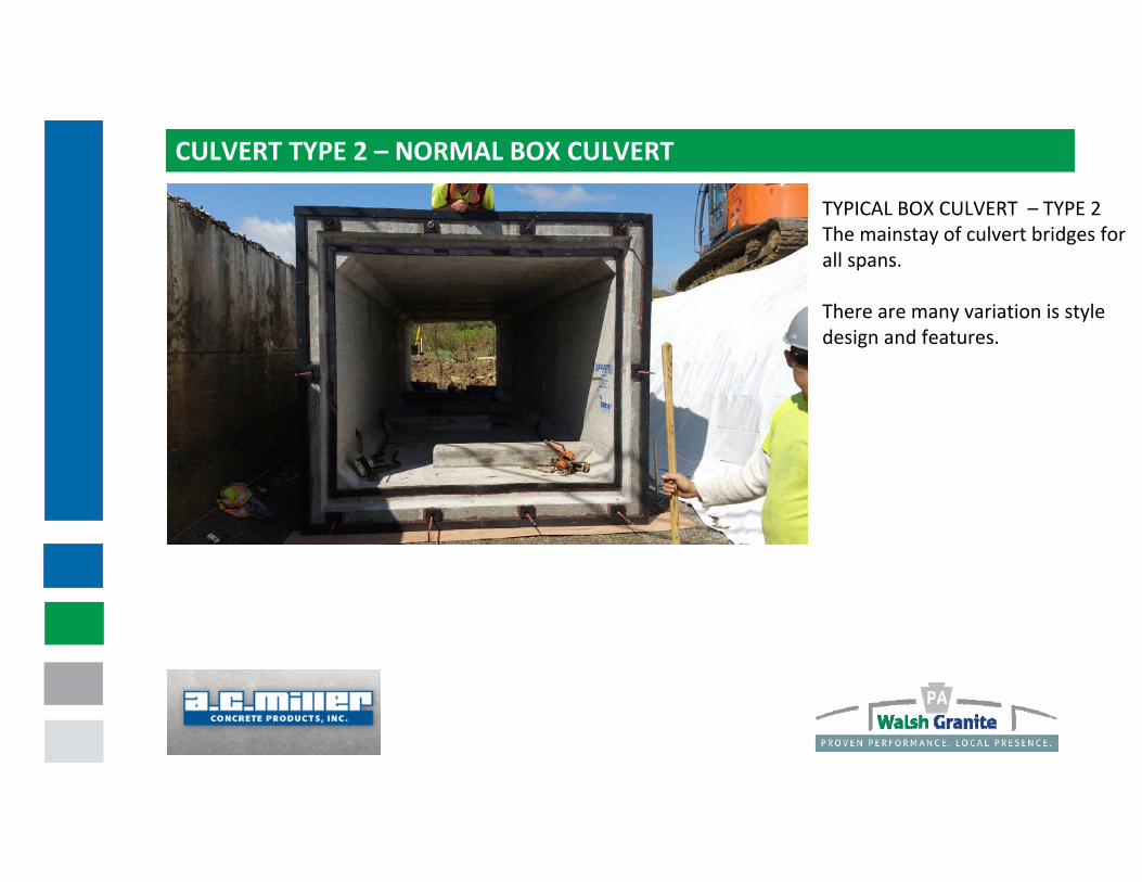
CULVERT TYPE 2 – NORMAL BOX CULVERT
TYPICAL BOX CULVERT – TYPE 2The mainstay of culvert bridges for all spans.
There are many variation is style design and features.
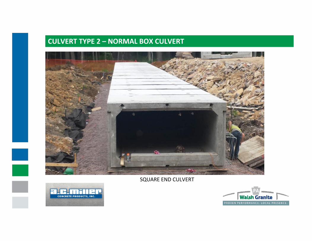
CULVERT TYPE 2 – NORMAL BOX CULVERT
SQUARE END CULVERT

CULVERT TYPE 2 – NORMAL BOX CULVERT
SKEWED END CULVERT SECTION

CULVERT TYPE 2 – NORMAL BOX CULVERT
SLICED ON THE SKEW CULVERT

CULVERT TYPE 2 – NORMAL BOX CULVERT
THEY CAN BE CURVED

CULVERT TYPE 2 – NORMAL BOX CULVERT
OR MITERED AT A CORNER

CULVERT TYPE 3 – RIGID FRAME
FRAME CULVERT – TYPE 3An alternate style that can solve some site specific issues.
Foundations can be cast‐in‐place or precast.
Foundations may be a slab or have pedestal walls.
Can be designed to prevent disturbing the stream or requiring a diversion or pumping.

CULVERT TYPE 3 – RIGID FRAME
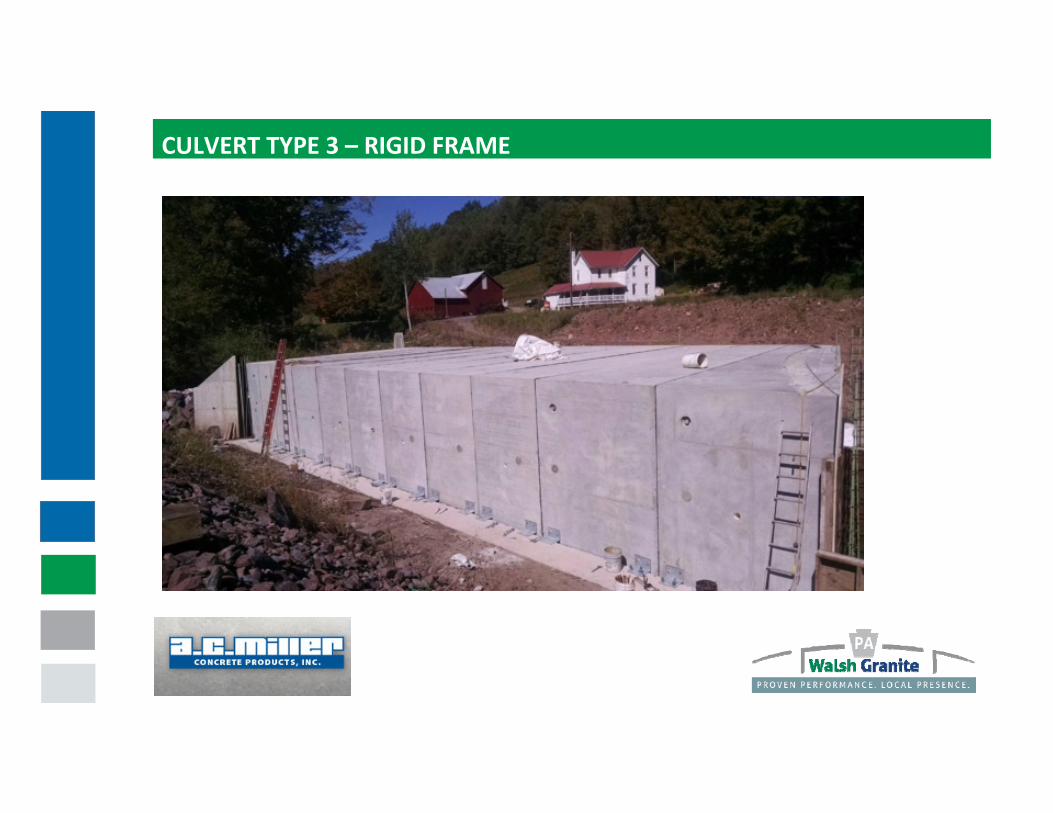
CULVERT TYPE 3 – RIGID FRAME

WING WALLS
WING WALLSWing walls are a part of nearly all culvert installations.
They come in many different styles and may be precast or cast in place.
Wing walls are the greatest distance from where the crane is placed and often drives the size of the crane needed.
They are irregular in shape and a great care is necessary when lifting and handling these sections.
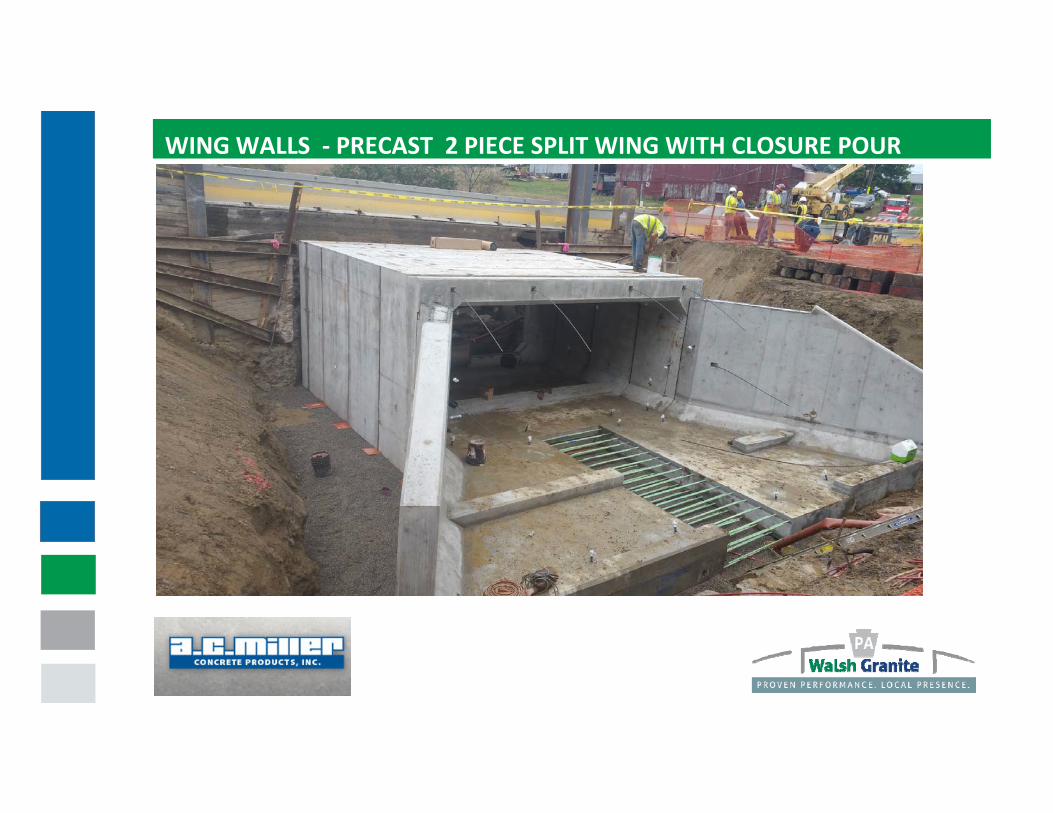
WING WALLS ‐ PRECAST 2 PIECE SPLIT WING WITH CLOSURE POUR

WING WALLS ‐ PRECAST FREE STANDING “L” WING

WING WALLS ‐ PRECAST MODULAR FREE STANDING WINGS
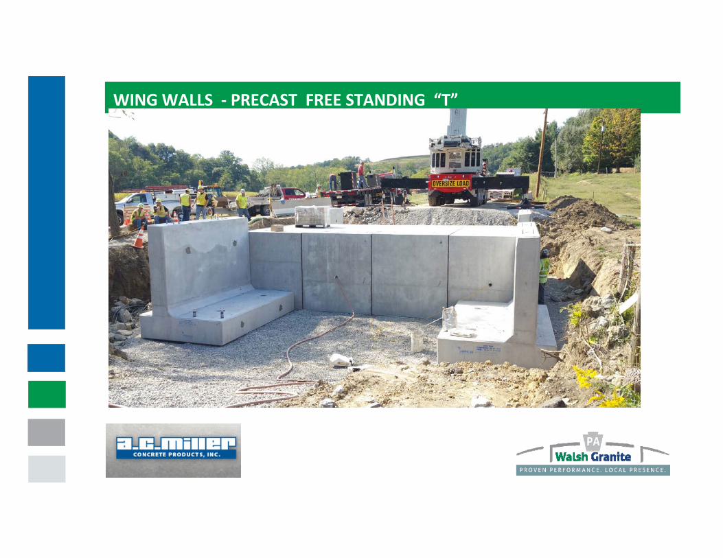
WING WALLS ‐ PRECAST FREE STANDING “T”WING WITH GUIDE RAIL BOLTS

PRECAST MOMENT SLAB ‐ SHORT WALLS WITH GUIDE RAIL BOLTS

DESIGN AND MANUFACTURE OF BOX CULVERT SECTIONS
1. Designed for in‐place and normal lifting loads
2. Manufactured on end
3. Dimensional tolerance is very tight with most tolerance +‐1/4”
4. The dimensions of the forms are checked prior to casting and
the pre‐pour tolerance is 2/3 the finished product tolerance
5. Concrete is tested at all stages from raw materials through the plastic state and after it has hardened and cured
6. The finished product dimension checks begin as soon as the molds are first opened.
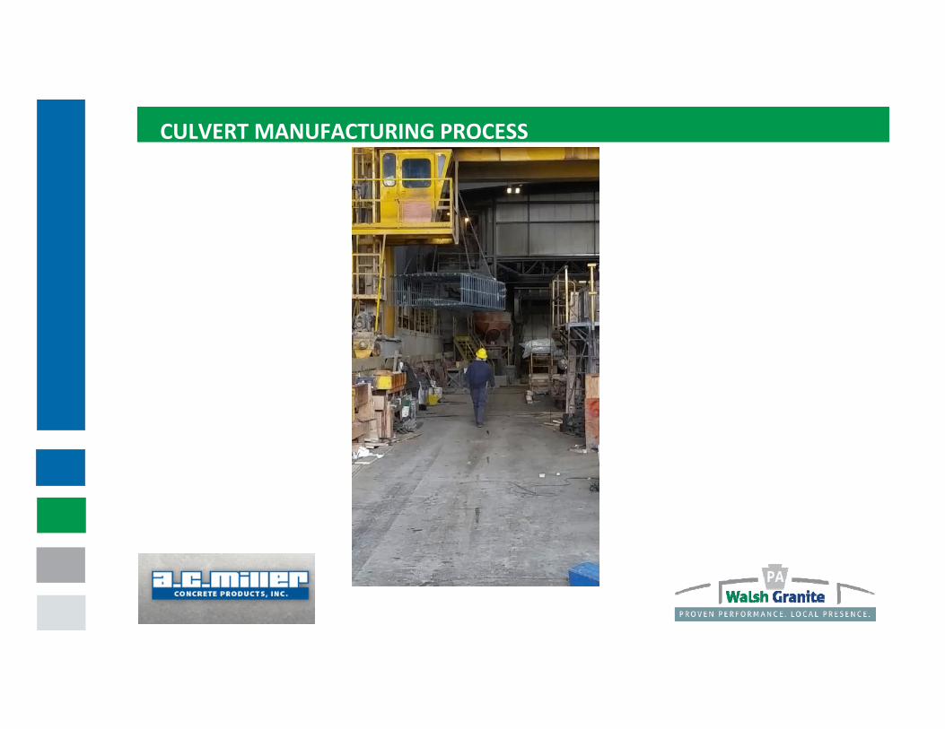
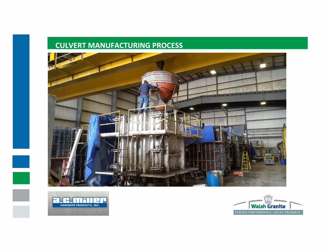
CULVERT MANUFACTURING PROCESS

CULVERT MANUFACTURING PROCESS

CULVERT MANUFACTURING PROCESS

CULVERT MANUFACTURING PROCESS

CULVERT MANUFACTURING PROCESS
CULVERT MANUFACTURING PROCESS

CULVERT MANUFACTURING PROCESS
CULVERT MANUFACTURING PROCESS

CULVERT MANUFACTURING PROCESS

CULVERT MANUFACTURING PROCESS

CULVERT MANUFACTURING PROCESS

CULVERT MANUFACTURING PROCESS

CULVERT MANUFACTURING PROCESS

CULVERT MANUFACTURING PROCESS

PROJECT PRE‐PLANNING

PRE‐PLANNING GENERAL INFORMATION
1. A.C. Miller will provide lifting devices that attach to the culvert for lifting and handling as well as pulling the sections together.
2. A technician from A.C. Miller is present for all installations. The technician is an advisor to observe and provide technical assistance for:
1) Bedding issues
2) Unloading, rotating and placing sections
3) Aligning and mating the joint
4) Post tensioning operation
5) Grouting procedures
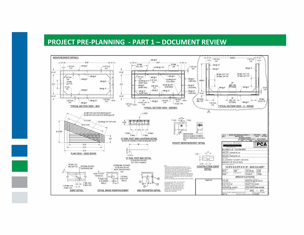
PROJECT PRE‐PLANNING ‐ PART 1 – DOCUMENT REVIEW / GENERAL INFO
DOCUMENT REVIEW
1. The P3 projects are a rapid design/build concept and the final project evolves and requires more pre‐planning.
2. Review the shop drawings for changes in thickness of the concrete member.

PROJECT PRE‐PLANNING ‐ PART 1 – DOCUMENT REVIEWSECTION WEIGHTS
THICKNESS & DIMENSION
EQUALIZERS

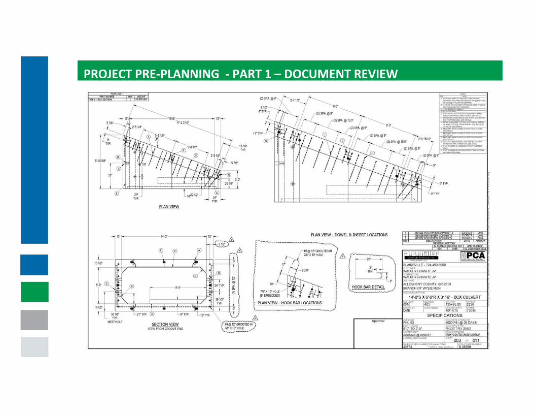
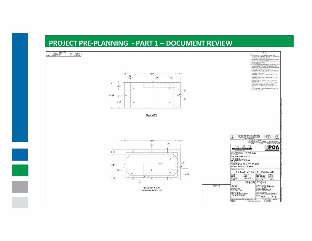
PROJECT PRE‐PLANNING ‐ PART 1 – DOCUMENT REVIEW
SHIPPED LOOSE ITEMS
PROJECT PRE‐PLANNING ‐ PART 1 – DOCUMENT REVIEW

PROJECT PRE‐PLANNING ‐ PART 1 – DOCUMENT REVIEW
PROJECT PRE‐PLANNING ‐ PART 1 – DOCUMENT REVIEW

PROJECT PRE‐PLANNING ‐ PART 1 – DOCUMENT REVIEW

PROJECT PRE‐PLANNING ‐ PART 1 – DOCUMENT REVIEW

PROJECT PRE‐PLANNING ‐ PART 1 – DOCUMENT REVIEW

PROJECT PRE‐PLANNING ‐ PART 1 – DOCUMENT REVIEW
SHIPPED LOOSE ITEMSFOR CURBS AND GUIDERAIL
PROJECT PRE‐PLANNING ‐ PART 1 – DOCUMENT REVIEW

PROJECT PRE‐PLANNING ‐ PART 1 – DOCUMENT REVIEW
SEQUENTIAL ORDERTO PULL STRANDS.
TENSION TO PULLSTRANDS ON EACHROTATION.

PROJECT PRE‐PLANNING – PART 2 – EQUIPMENT NEEDS
EQUIPMENT REQUIREMENTS – BRIDGE BUILDER SUPPLIED1. A minimum of three ladders: tall enough to access the top of the
box culvert, access the lifters and be used for post tensioning operations
2. Shovels and rakes for adjusting the bedding if it is necessary3. Generator and extension cords for power tools and running the
post tensioning jack4. Air compressor for post tensioning operations5. Angle grinder with metal cut off wheels and a gas powered saw
with metal and concrete blades6. Hand tools including level, screw drivers, hammers, string lines,
chalk line, tape measures, long tape measures and utility knives(some with hooked blades)
7. Crane rigging (more details will be provided later)
PROJECT PRE‐PLANNING – PART 3 – MINIMUM CREW SIZE
MAN‐POWER REQUIREMENTS
1. A minimum of two workers should be assigned to unloading operations and a third person is helpful if the sections must berotated. At least one worker should have training on rigging and crane signals.
2. A minimum of four workers should be assigned to the placing or setting operations. At least one worker should also have training on rigging and crane signals.
3. An equipment operator should be present in the event that heavy equipment is needed. Air compressor needed for post tensioning operations.
4. A minimum of five workers should be assigned to post tensioning and grout operations. During intermediate post tensioning pulls the unloading crew can stage the next precast units.

PROJECT PRE‐PLANNING – PART 4 – SITE SPACE REQUIREMENTSSPACE REQUIREMENTS1. You need a nearly‐level area large enough to fit both the fully setup crane
and the delivery truck. Remember to factor in the width of load if the culvert sections are being delivered “laid down.”
2. In addition to the crane and delivery truck, an area near the culvert is needed for the technician’s pickup with a 24 ft. long trailer. The grouting equipment is permanently mounted to the trailer and moving the unit in and out for post‐tensioning and grouting will add delay time.
3. If the culvert is delivered “laid down” a level area is needed to rotate the precast units.
4. The base of the excavation must be wide enough for string lines and a walkway (about 4 ft.) on each side of the precast units.
5. A minimum clearance of 3 ft. at jacking points and 18” at dead anchor points is needed between the culvert and obstruction such as shoring.
PROJECT PRE‐PLANNING – PART 5 ‐ BEDDING MATERIALS
BEDDING MATERIALS AND ISSSUES.1. Standard bedding material is #2A or #8 stone with a minimum 12” depth2. Material volume or excavation volume may change from contract
documents if floor thickness changes3. Bedding must be as flat and even as possible and on the proper grade4. Installing cutoff walls first if they called for helps to contain bedding
material and establish grade5. Humps in the bedding will cause gaps in the joints at the top6. Bellies in the bedding will cause gaps in the joints at the bottom7. Combinations of small humps and bellies can cause the culvert sections to
lean to one side and steps in the top and bottom slabs8. Soft and saturated bedding will cause steps, leans and gaps in the joints

SITE PREPARATION – BEDDING
BY FAR THE QUALITY OF THE BEDDING PREPARED BY THE CONTRACTOR HAS THE BIGGEST IMPACT ON THE DIFFICULTY OF INSTALLATION AND QUALITY OF THE FINAL PRODUCT.

PROJECT PRE‐PLANNING – PART 6 – MAINTAIN STREAM PUMPING OR DIVERSIONDON’T FORGET TO KEEP THE PUMPS RUNNING

PROJECT PRE‐PLANNING – PART 7 – CRANE PLACEMENT AND SIZING

PROJECT PRE‐PLANNING – PART 7 – CRANE PLACEMENT AND SIZING

PROJECT PRE‐PLANNING – PART 7 – CRANE PLACEMENT AND SIZING

SITE PREPARATION
SITE PREPARATION – BEDDING
Did We Mention This…
BY FAR THE QUALITY OF THE BEDDING PREPARED BY THE CONTRACTOR HAS THE BIGGEST IMPACT ON THE DIFFICULTY OF INSTALLATION AND QUALITY OF THE FINAL PRODUCT.

SITE PREPARATION – BEDDING
BEDDING MATERIALS AND ISSSUES1. Bedding must be flat & as even as possible and on the proper
grade2. Installing cutoff walls first if they called for helps to contain
bedding material and establish grade3. Humps in the bedding will cause gaps in the joints at the top4. Bellies in the bedding will cause gaps in the joints at the bottom 5. Combinations of small humps and bellies can cause the culvert
sections to lean to one side and steps in the top and bottom slabs6. Soft and saturated bedding will cause steps, leans and gaps in the
joints

SITE PREPARATION – BEDDING
The ultimate bedding:A mud slab or leveling pad provides a flat, even dry, firm bedding. There is no loose material that can get into the joints.

SITE PREPARATION – BEDDING
Typical stone bedding:Note that the cutoff wall is in place and helps to contain the bedding. Non‐phased construction will allow both cut off walls to be in place.
Related Documents