Bounded-distortion Piecewise Mesh Parameterization O. Sorkine, D. Cohen-Or, R. Goldenthal, D. Lischinski IEEE Visualization 2002 July 2002

Bounded-distortion Piecewise Mesh Parameterization
Dec 30, 2015
Bounded-distortion Piecewise Mesh Parameterization O. Sorkine, D. Cohen-Or, R. Goldenthal, D. Lischinski IEEE Visualization 2002. July 2002. Existing methods – main ideas. Partition/cut the mesh in preprocess Interactive user input Normals bucketing Region growing from feature curves - PowerPoint PPT Presentation
Welcome message from author
This document is posted to help you gain knowledge. Please leave a comment to let me know what you think about it! Share it to your friends and learn new things together.
Transcript

Bounded-distortion Piecewise Mesh Parameterization
O. Sorkine, D. Cohen-Or, R. Goldenthal, D. Lischinski
IEEE Visualization 2002
July 2002

Existing methods – main ideas Partition/cut the mesh in preprocess
Interactive user input Normals bucketing Region growing from feature curves
Flatten each patch by energy minimization Convex mapping Harmonic mapping Conformal mapping
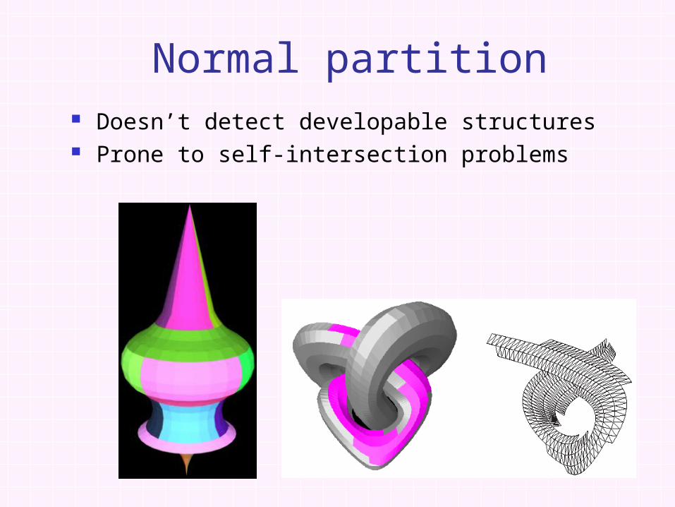
Normal partition Doesn’t detect developable structures Prone to self-intersection problems

Various flattening methods
Floater 97, Lévy and Mallet 98 Maillot et al. 93, Eck et al. 95, Lee et al. 98 Sander et al. 01, Gu et al. 02 Haker et al. 00, Sheffer 02, Lévy et al. 02 Zigelman et al. 02
Bennis et al. 91
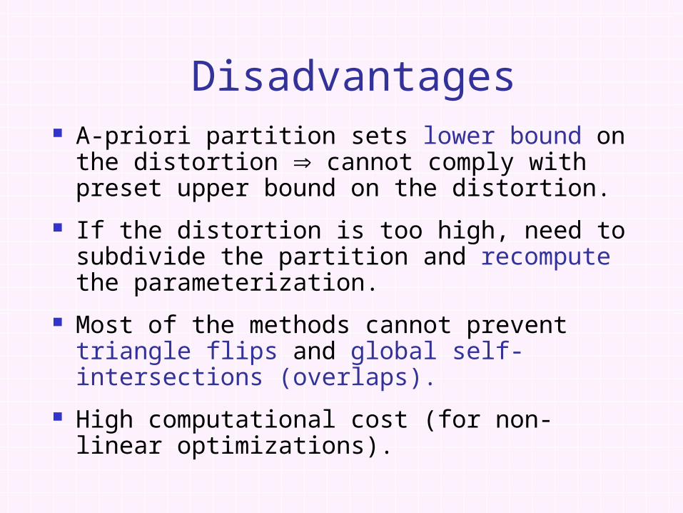
Disadvantages A-priori partition sets lower bound on the
distortion cannot comply with preset upper bound on the distortion.
If the distortion is too high, need to subdivide the partition and recompute the parameterization.
Most of the methods cannot prevent triangle flips and global self-intersections (overlaps).
High computational cost (for non-linear optimizations).

Our contribution Parameterization with bounded
distortion Simultaneous partition and
parameterization Valid parameterization –
no self-intersections

Algorithm overview
Greedy algorithm: grow one patch at a time, until no more vertices can be added.
At each step, attempts to flatten the “best” vertex adjacent to the current patch.
The distortion of each mesh triangle is guaranteed to be below specified threshold.

Algorithm overview Select random seed triangle, flatten it.
Maintain a priority queue of the vertices adjacent to the current patch.
Flatten triangles adjacent to current patch: At each step, take the best vertex off the queue Check for self-intersections
Stop when no triangles can be added to the patch, and start a new one.

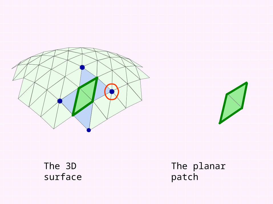
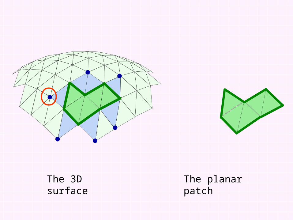
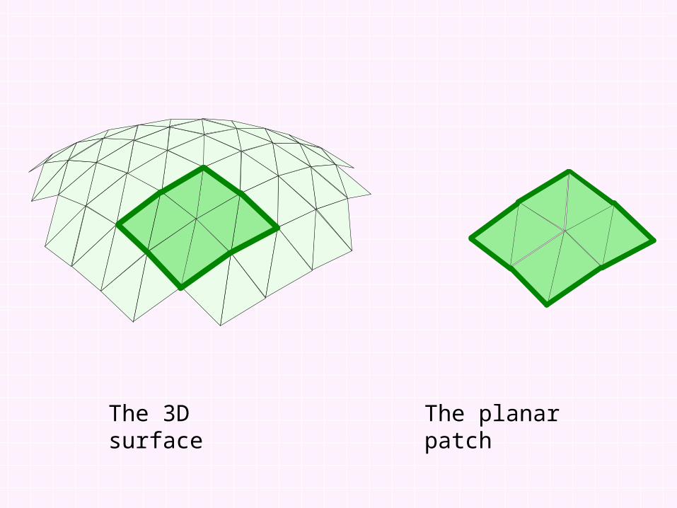
The 3D surface

The 3D surface
The planar patch

The 3D surface
The planar patch

The 3D surface
The planar patch
The 3D surface
The planar patch

The 3D surface
The planar patch

The 3D surface
The planar patch

The 3D surface
The planar patch

The 3D surface
The planar patch

The 3D surface
The planar patch
The 3D surface
The planar patch

The 3D surface
The planar patch

The 3D surface
The planar patch
The 3D surface
The planar patch

The distortion metric
321
321213132
232
,,
,,,,,,),(
),(,:
ppp
qppqppqpptsS
RtsdenoteRRS
ppp
p
In 2D In 3D
S
p1p2
p3
q1 q2
q3
T T’
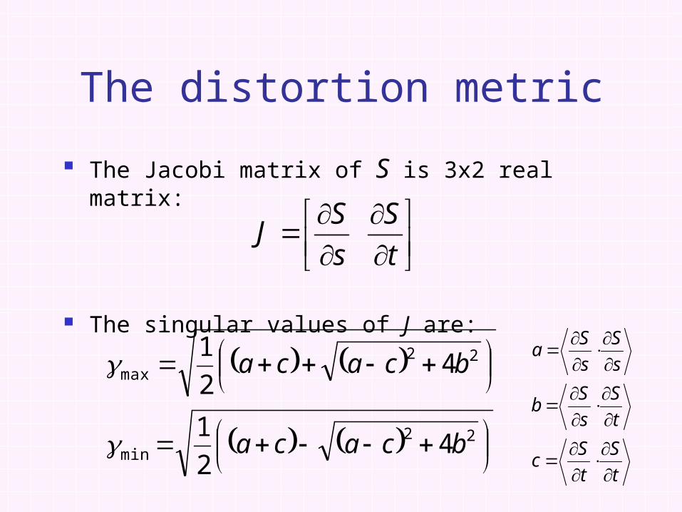
The Jacobi matrix of S is 3x2 real matrix:
The singular values of J are:
The distortion metric
t
S
s
SJ
22min
22max
42
1
42
1
bcaca
bcaca
t
S
t
Sc
t
S
s
Sb
s
S
s
Sa

The distortion metric
min 1
max1
min
max
v
v
Sv
Sv

The values max and min are the maximal stretching and shrinking caused to a unit-length vector by the mapping S.
We want to equally “punish” stretch and shrink, therefore we define:
D(T, T’) = max{max , 1/ min }
Any other reasonable metric can be used!
The distortion metric

Flattening a single vertex
T1
V
T2
t2
v1
t1
v2
t2t1
v

The obtained position v can be used as initial guess for a relaxation procedure that finds better position v’ (for example, minimizes the average distortion of triangles incident to the vertex).
However, it is slower, and the initial guess performs well in practice.
Flattening a single vertex

Maximal distortion caused to the triangles flattened with the vertex. If it’s greater than the threshold, the grade is set to zero and the vertex can’t be flattened in the current patch!
The ratio between patch area and squared perimeter (to create round patches with small boundary length).
Crease angles or other segmentation information.
More criteria…
Vertex grade components

Local self-intersection – triangle flipping
Checking self-intersections
V
t1 t2

Global self-intersections: maintain space partition data structure, check the new triangles with the existing boundary triangles.
Checking self-intersections
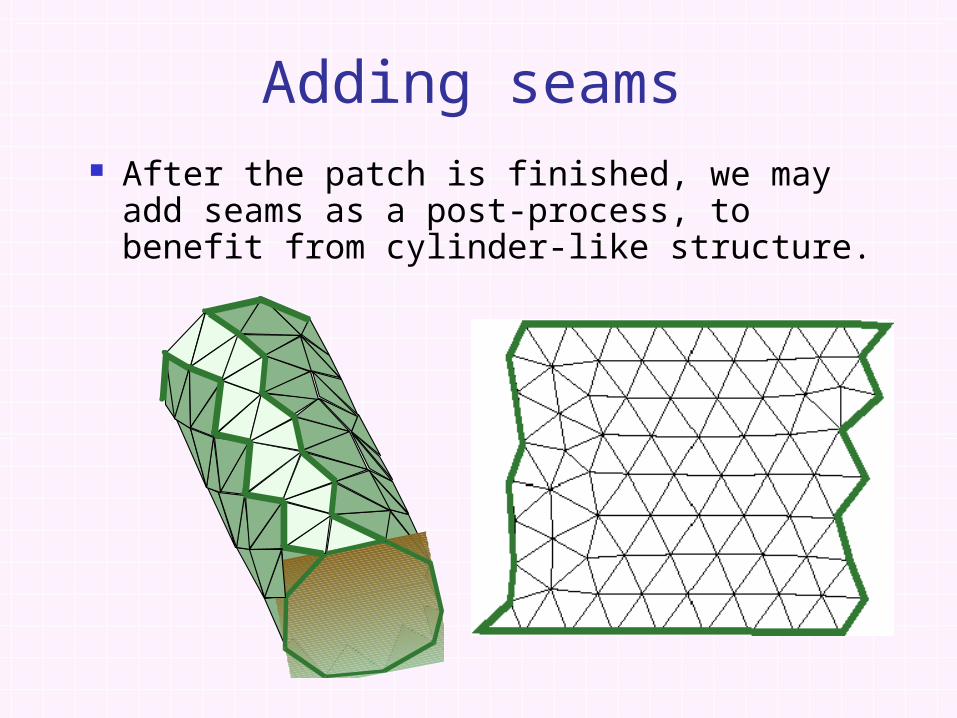
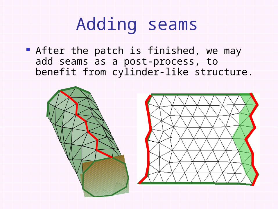
After the patch is finished, we may add seams as a post-process, to benefit from cylinder-like structure.
Adding seams
After the patch is finished, we may add seams as a post-process, to benefit from cylinder-like structure.
Adding seams

Results

Results
1.01.0
1.51.5
2.02.0
3.03.03.03.0
1.01.0
1.51.5
2.02.0
3.03.0
1.01.0
1.51.5
2.02.0
3.03.0

Results
Bounding the area/perimeter2 ratio...

Results

Results

Comparison with relaxation technique, normal bucketing partition
Conclusions about our method: Much faster. Lower average distortion. Boundary length – sometimes the same,
sometimes longer…
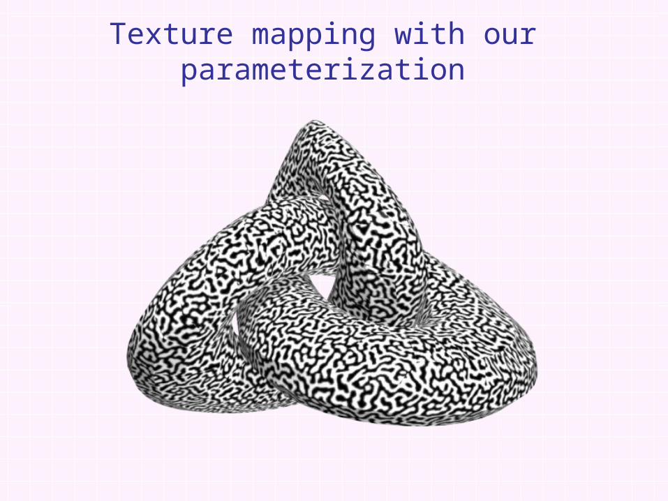
Texture mapping with our parameterization

Texture mapping with our parameterization
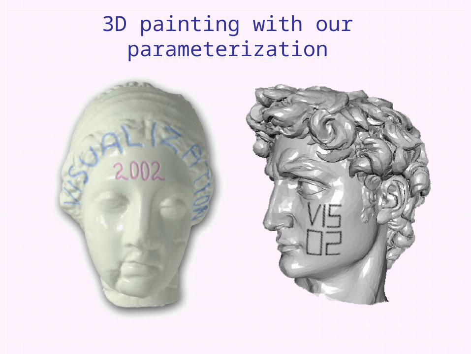
3D painting with our parameterization

Thank you!
Related Documents