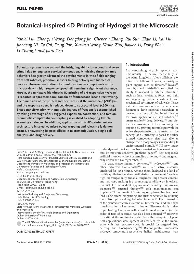
www.afm-journal.de © 2019 WILEY-VCH Verlag GmbH & Co. KGaA, Weinheim 1907377 (1 of 10) Full PaPer Botanical-Inspired 4D Printing of Hydrogel at the Microscale Yanlei Hu, Zhongyu Wang, Dongdong Jin, Chenchu Zhang, Rui Sun, Ziqin Li, Kai Hu, Jincheng Ni, Ze Cai, Deng Pan, Xuewen Wang, Wulin Zhu, Jiawen Li, Dong Wu,* Li Zhang,* and Jiaru Chu Botanical systems have evolved the intriguing ability to respond to diverse stimuli due to long-term survival competition. Mimicking these dynamic behaviors has greatly advanced the developments in wide fields ranging from soft robotics, precision sensors to drug delivery and biomedical devices. However, realization of stimuli-responsive components at the microscale with high response speed still remains a significant challenge. Herein, the miniature biomimetic 4D printing of pH-responsive hydrogel is reported in spatiotemporal domain by femtosecond laser direct writing. The dimension of the printed architectures is at the microscale (<10 2 m) µ and the response speed is reduced down to subsecond level ( 500 ms). < Shape transformation with multiple degrees of freedom is accomplished by taking advantage of pH-triggered expansion, contraction, and torsion. Biomimetic complex shape-morphing is enabled by adopting flexible scanning strategies. In addition, application of this 4D-printed micro- architecture in selective micro-object trapping and releasing is demon- strated, showcasing its possibilities in micromanipulation, single-cell analysis, and drug delivery. DOI: 10.1002/adfm.201907377 Prof. Y. L. Hu, Z. Y. Wang, R. Sun, Z. Q. Li, K. Hu, J. C. Ni, Z. Cai, D. Pan, W. L. Zhu, Prof. J. W. Li, Prof. D. Wu, Prof. J. R. Chu Hefei National Laboratory for Physical Sciences at the Microscale and CAS Key Laboratory of Mechanical Behavior and Design of Materials Department of Precision Machinery and Precision Instrumentation University of Science and Technology of China Hefei 230026, China E-mail: [email protected] D. D. Jin, Prof. L. Zhang Department of Mechanical and Automation Engineering The Chinese University of Hong Kong Hong Kong 999077, China E-mail: [email protected] Prof. C. C. Zhang Institute of Industry and Equipment Technology Hefei University of Technology Hefei 230009, China Prof. X. W. Wang State Key Laboratory of Advanced Technology for Materials Synthesis and Processing International School of Materials Science and Engineering Wuhan University of Technology Wuhan 430070, China The ORCID identification number(s) for the author(s) of this article can be found under https://doi.org/10.1002/adfm.201907377. 1. Introduction Shape-morphing organic systems exist ubiquitously in nature, particularly in the plant kingdom. After sufficient evo- lution for billions of years, a variety of plant organs such as flowers, [1] leaves, [2] tendrils, [3] and nutshells [4] are gifted the ability to respond to external stimuli [5,6] such as heat, moisture, force, and light via regulating tissue constituent and mechanical asymmetry of cell walls. These natural stimuli-responsive dynamic con- formations have inspired researchers to develop a variety of biomimetic devices for broad applications in soft robotics, [7,8] smart textiles, [9] drug delivery, [10] and bio- medical machines. [11] By combining the ongoing 3D printing technologies with the active shape-transformative materials, the concept of 4D printing is posed to realize printed components that are able to change their morphologies responding to environmental stimuli. [12] Till now, many useful dynamic devices have been created such as smart actua- tors by moisture-sensitive graphene paper, [7] light-responsive artificial muscles without assembling or joints, [13] and magneti- cally driven soft hydrogel robot. [14] To date, shape memory polymers, [15] hydrogels, [16,17] and other extracted biomaterials [18] are main active materials employed for 4D printing. Among them, hydrogel is a kind of readily synthetized material with distinct advantages [19] such as high biocompatibility, tunable toughness, high water content, and low cost, making it a promising candidate as interfacial material for biomedical applications including noninvasive diagnosis, [20] targeted therapy, [21] cells manipulation, and implants. [22] Biomimetic 4D printing of hydrogel has been real- ized using direct ink printing and further actuated by utilizing the anisotropic swelling behavior in water. [5] The dimension of the printed structures is at the millimeter level and the shape transformation takes several minutes. Electrostatically aniso- tropic hydrogel actuator with a fast thermal response (on the order of tens of seconds) has also been obtained. [23] However, it is still at the millimeter scale. From the viewpoint of prac- tical applications, development of architectures at the micro- scale with fast response speed is crucial for targeted drug delivery and bioengineering. [24] Reconfigurable microscale hydrogel temperature-responsive helical architectures have Adv. Funct. Mater. , 2020 30, 1907377 Printed by [University Of Science - 218.104.071.166 - /doi/epdf/10.1002/adfm.201907377] at [20/07/2021].

Welcome message from author
This document is posted to help you gain knowledge. Please leave a comment to let me know what you think about it! Share it to your friends and learn new things together.
Transcript
www.afm-journal.de
© 2019 WILEY-VCH Verlag GmbH & Co. KGaA, Weinheim1907377 (1 of 10)
Full PaPer
Botanical-Inspired 4D Printing of Hydrogel at the Microscale
Yanlei Hu, Zhongyu Wang, Dongdong Jin, Chenchu Zhang, Rui Sun, Ziqin Li, Kai Hu,
Jincheng Ni, Ze Cai, Deng Pan, Xuewen Wang, Wulin Zhu, Jiawen Li, Dong Wu,*
Li Zhang,* and Jiaru Chu
Botanical systems have evolved the intriguing ability to respond to diverse
stimuli due to long-term survival competition. Mimicking these dynamic
behaviors has greatly advanced the developments in wide fields ranging
from soft robotics, precision sensors to drug delivery and biomedical
devices. However, realization of stimuli-responsive components at the
microscale with high response speed still remains a significant challenge.
Herein, the miniature biomimetic 4D printing of pH-responsive hydrogel
is reported in spatiotemporal domain by femtosecond laser direct writing.
The dimension of the printed architectures is at the microscale (<102 m) µ
and the response speed is reduced down to subsecond level ( 500 ms). <
Shape transformation with multiple degrees of freedom is accomplished
by taking advantage of pH-triggered expansion, contraction, and torsion.
Biomimetic complex shape-morphing is enabled by adopting flexible
scanning strategies. In addition, application of this 4D-printed micro-
architecture in selective micro-object trapping and releasing is demon-
strated, showcasing its possibilities in micromanipulation, single-cell
analysis, and drug delivery.
DOI: 10.1002/adfm.201907377
Prof. Y. L. Hu, Z. Y. Wang, R. Sun, Z. Q. Li, K. Hu, J. C. Ni, Z. Cai, D. Pan, W. L. Zhu, Prof. J. W. Li, Prof. D. Wu, Prof. J. R. ChuHefei National Laboratory for Physical Sciences at the Microscale and CAS Key Laboratory of Mechanical Behavior and Design of MaterialsDepartment of Precision Machinery and Precision InstrumentationUniversity of Science and Technology of ChinaHefei 230026, ChinaE-mail: [email protected]. D. Jin, Prof. L. ZhangDepartment of Mechanical and Automation EngineeringThe Chinese University of Hong KongHong Kong 999077, ChinaE-mail: [email protected]
Prof. C. C. ZhangInstitute of Industry and Equipment TechnologyHefei University of TechnologyHefei 230009, China
Prof. X. W. WangState Key Laboratory of Advanced Technology for Materials Synthesis and ProcessingInternational School of Materials Science and EngineeringWuhan University of TechnologyWuhan 430070, China
The ORCID identification number(s) for the author(s) of this article can be found under https://doi.org/10.1002/adfm.201907377.
1. Introduction
Shape-morphing organic systems exist
ubiquitously in nature, particularly in the plant kingdom. After sufficient evo-
lution for billions of years, a variety of
plant organs such as flowers,[1] leaves,[2] tendrils,[3] and nutshells[4] are gifted the
ability to respond to external stimuli[5,6] such as heat, moisture, force, and light
via regulating tissue constituent and mechanical asymmetry of cell walls. These
natural stimuli-responsive dynamic con-formations have inspired researchers to
develop a variety of biomimetic devices
for broad applications in soft robotics,[7,8] smart textiles,[9] drug delivery, [10] and bio-
medical machines.[11] By combining the ongoing 3D printing technologies with the
active shape-transformative materials, the concept of 4D printing is posed to realize
printed components that are able to change their morphologies responding to
environmental stimuli.[12] Till now, many
useful dynamic devices have been created such as smart actua-tors by moisture-sensitive graphene paper,[7] light-responsive
artificial muscles without assembling or joints,[13] and magneti-cally driven soft hydrogel robot.[14]
To date, shape memory polymers,[15] hydrogels,[16,17] and other extracted biomaterials[18] are main active materials
employed for 4D printing. Among them, hydrogel is a kind of readily synthetized material with distinct advantages[19] such as
high biocompatibility, tunable toughness, high water content,
and low cost, making it a promising candidate as interfacial material for biomedical applications including noninvasive
diagnosis,[20] targeted therapy, [21] cells manipulation, and implants.[22] Biomimetic 4D printing of hydrogel has been real-
ized using direct ink printing and further actuated by utilizing the anisotropic swelling behavior in water.[5] The dimension
of the printed structures is at the millimeter level and the shape transformation takes several minutes. Electrostatically aniso-
tropic hydrogel actuator with a fast thermal response (on the
order of tens of seconds) has also been obtained.[23] However, it is still at the millimeter scale. From the viewpoint of prac-
tical applications, development of architectures at the micro-scale with fast response speed is crucial for targeted drug
delivery and bioengineering.[24] Reconfigurable microscale hydrogel temperature-responsive helical architectures have
Adv. Funct. Mater. , 2020 30, 1907377
Printed by [University O
f Science - 218.104.071.166 - /doi/epdf/10.1002/adfm.201907377] at [20/07/2021].

www.afm-journal.dewww.advancedsciencenews.com
1907377 (2 of 10) © 2019 WILEY-VCH Verlag GmbH & Co. KGaA, Weinheim
been reported and the response time is hopeful to be enhanced
by increasing the rate of heating.[25] Although fabrication and actuation of hydrogels has been intensively studied,[17,26] facile
4D printing of environmentally responsive hydrogel structures with complex 3D geometry, microscale dimension, on-demand
actuation ability, and fast transforming speed is still in high demand.
Femtosecond laser direct writing enabled by two-photon
absorption has arresting features of nanometer spatial resolution, ultralow thermal effect, and excellent geometry designability.[27]
Tremendous endeavors have been made to create 3D hydrogel microstructures with femtosecond laser towards promising
photonic and biomedical applications.[28] Microscale hydrogel structures with rapid swelling capability has been demonstrated
by Shear and co-workers. [29] 4D printing of hydrogel with high structural complexity and multiple freedoms of shape-morphing
remains to be further explored. Here, we utilize femtosecond
laser direct writing to print stimuli-responsive hydrogel in spati-otemporal domain. Plant-like microscale 3D hydrogel structures
are created with high actuation speed ( 500 ms) by changing the <pH value of the liquid environment. By tailoring the laser scan-
ning strategy, multiple degrees of freedom including not only expansion, contraction, and torsional deformation, but also com-
plicated wrinkling and curling distortion, have been realized. Complex microcages are constructed to demonstrate their ability
to selectively trap and release micro-objects, which holds great
potential for biomedical applications.
2. Results and Discussion
2.1. Fabrication and Swelling Properties of the Hydrogel
A pH-responsive hydrogel containing a large amount of car-
boxyl groups in the side chain is used. In order to realize large
swelling ratio, the crosslinking density should be controlled to a relatively low level. However, low crosslinking density results
in poor mechanical strength of the printed hydrogel, making the hydrogel structures too soft to constitute 3D freestanding
structures. Therefore, inevitable trade-offs between the swelling ratio and the mechanical stability have to be considered in the
compositional design of the materials. Here, polyvinylpyrro-lidone (PVP) is added to increase the solution viscosity, which
facilitates the construction of complex 3D hydrogel microstruc-
tures (see Experimental Section and Figure S1, Supporting Information).
The hydrogel samples are fabricated by femtosecond laser direct writing (Figure 1 a). When they are immersed in a solu-
tion with a pH value greater than the ionization threshold (pH = 9),the pendant acidic (carboxylic) groups in acrylic acid
(AAc) can release protons and thus be ionized. The electrostatic repulsion forces between carboxylate ions repel other molecular
chains, resulting in significant expansion of the polymer grid size (Figure 1b). On the contrary, the carboxyl groups accept
protons and thus be deionized when the PH value is lower than
9. The ionization of the carboxyl groups is much stronger than the deionization. Consequently, the hydrogel exhibits strong
and weak swelling in alkaline and acid solutions, respectively (Figure S2, Supporting Information).
In order to study the expansion and contraction character-
istics of this hydrogel, a cubic plate (side length 40 L = µm) and a circular plate (diameter 40 m) are prepared and D = µ
measured. In order to avoid the restriction of substrate on the motility of the structure, the plates are fabricated on an
elongated cylindrical base with a height of 10 m (Figure 1c). µWhen the as-prepared structures are placed in NaOH solution
having a pH 9, significantly rapid expansion is observed >within 0.5 s. After that, by dropping a sufficient amount of
dilute HCl solution, the structures can deswell quickly and
the whole restoring process can be completed in 0.33 s. In brief, as soon as the pH exceeds the ionization threshold, the
printed hydrogel structures respond at the subsecond level. According to the experimental observation, the fast shape-
morphing ratio mainly results from the small size of the printed microstructure. It takes much less time for the dif-
fusion of acids or alkalis over the microstructures than the macroscale structures, thus facilitating fast actuation speed.
Therefore, the transformation speed of printed hydrogel
microstructures can be tuned by the amount and frequency of liquid dropping. Note that due to the swelling property of
the hydrogel, the size of the contracted state is still slightly larger than the size of primary design (Figures S3 and S4,
Supporting Information).Referring to the definition of strain in material mechanics,
we define the expansion ratio of the hydrogel structures in expanded state (or contracted state) as the ratio of the length
change (expansion or contraction) to the designed length, that is, the expansion ratio for the expanded state is:
=−
expansionexpansion design
design
L L
L (1)
and the expansion ratio for the contracted state is:
=−
contractcontract design
design
L L
L (2)
As shown in Figure 1d, the typical εexpansion measured in our
experiments are 0.53 and 0.52, and the εcontract are 0.072 and 0.066 for the cubic and circular plates, respectively. In order
to quantify the realistic deformation range of the pH-respon-sive structure during the swelling–deswelling process, relative
expansion ratio (RER) is defined to be the ratio of the length
difference between the expansion state and the contracted state to the contracted length:
=ER expansion contract
contract
L L
L (3)
Therefore, the RER value can reflect the relative deformation capacity of the structures. As shown in Figure 1c, the typical
RER of the hydrogel is measured to be 0.43. The values for
both cubic and circular plates are almost the same, revealing good homogeneity and isotropic swelling characteristics of
the hydrogel. To evaluate the fatigue resistance of the printed hydrogel, the expansion ratio of the cubic plate is measured
with multiple expansion and contraction cycles (Figure 1e), vali-dating good repetition performance of the hydrogel.
Adv. Funct. Mater. , 2020 30, 1907377
Printed by [University O
f Science - 218.104.071.166 - /doi/epdf/10.1002/adfm.201907377] at [20/07/2021].
www.afm-journal.dewww.advancedsciencenews.com
1907377 (3 of 10) © 2019 WILEY-VCH Verlag GmbH & Co. KGaA, Weinheim
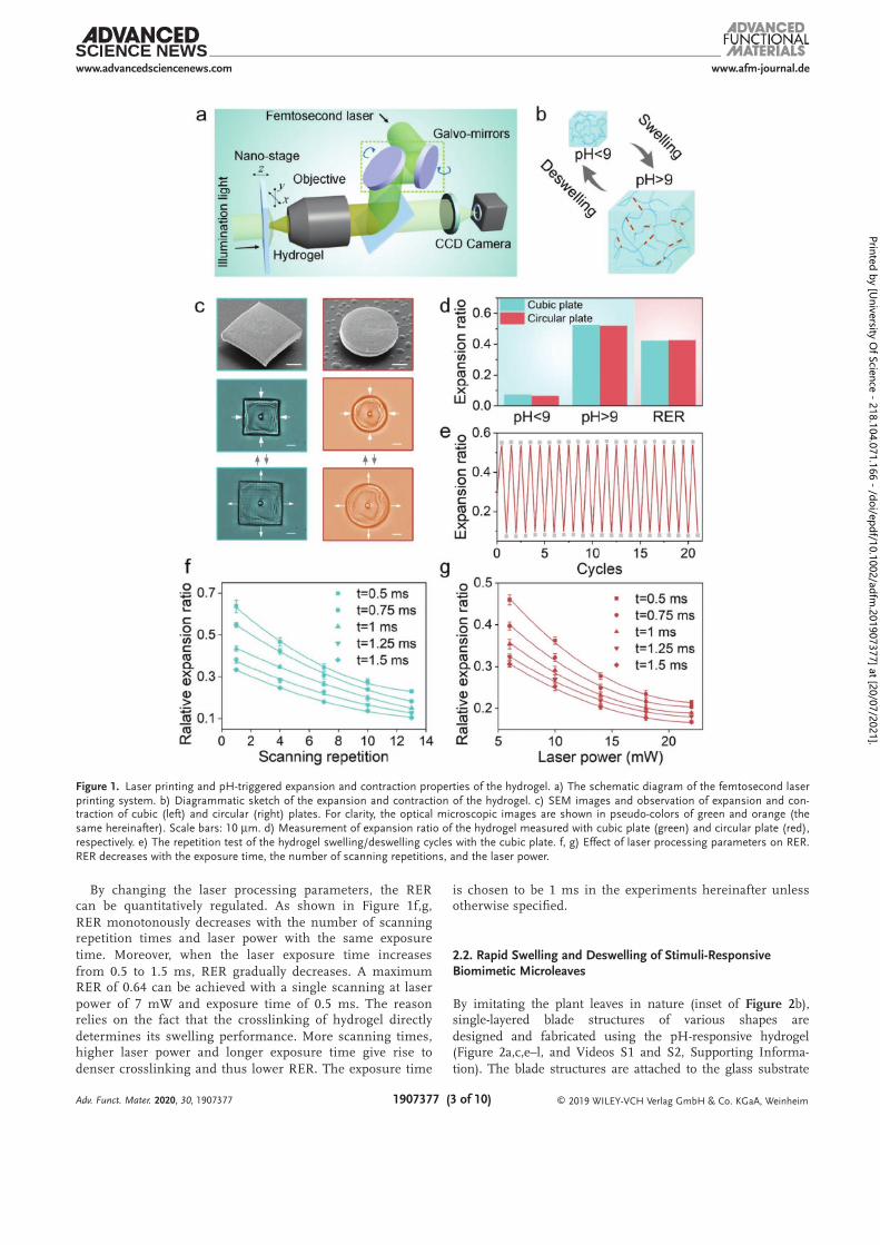
By changing the laser processing parameters, the RER can be quantitatively regulated. As shown in Figure 1f,g,
RER monotonously decreases with the number of scanning repetition times and laser power with the same exposure
time. Moreover, when the laser exposure time increases
from 0.5 to 1.5 ms, RER gradually decreases. A maximum RER of 0.64 can be achieved with a single scanning at laser
power of 7 mW and exposure time of 0.5 ms. The reason relies on the fact that the crosslinking of hydrogel directly
determines its swelling performance. More scanning times, higher laser power and longer exposure time give rise to
denser crosslinking and thus lower RER. The exposure time
is chosen to be 1 ms in the experiments hereinafter unless otherwise specified.
2.2. Rapid Swelling and Deswelling of Stimuli-Responsive Biomimetic Microleaves
By imitating the plant leaves in nature (inset of Figure 2 b), single-layered blade structures of various shapes are
designed and fabricated using the pH-responsive hydrogel (Figure 2a,c,e–l, and Videos S1 and S2, Supporting Informa-
tion). The blade structures are attached to the glass substrate
Adv. Funct. Mater. , 2020 30, 1907377
Figure 1. Laser printing and pH-triggered expansion and contraction properties of the hydrogel. a) The schematic diagram of the femtosecond laser printing system. b) Diagrammatic sketch of the expansion and contraction of the hydrogel. c) SEM images and observation of expansion and con-traction of cubic (left) and circular (right) plates. For clarity, the optical microscopic images are shown in pseudo-colors of green and orange (the same hereinafter). Scale bars: 10 m. d) Measurement of expansion ratio of the hydrogel measured with cubic plate (green) and circular plate (red), µrespectively. e) The repetition test of the hydrogel swelling/deswelling cycles with the cubic plate. f, g) Effect of laser processing parameters on RER. RER decreases with the exposure time, the number of scanning repetitions, and the laser power.
Printed by [University O
f Science - 218.104.071.166 - /doi/epdf/10.1002/adfm.201907377] at [20/07/2021].
www.afm-journal.dewww.advancedsciencenews.com
1907377 (4 of 10) © 2019 WILEY-VCH Verlag GmbH & Co. KGaA, Weinheim
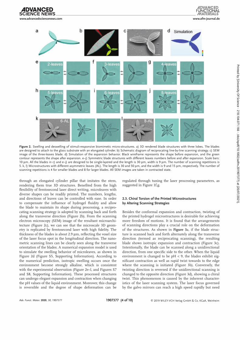
through an elongated cylinder pillar that imitates the stem,
rendering them true 3D structures. Benefited from the high flexibility of femtosecond laser direct writing, microleaves with
diverse shapes can be readily printed. The numbers, lengths, and directions of leaves can be controlled with ease. In order
to compensate the influence of hydrogel fluidity and allow the blade to maintain its shape during processing, a recipro-
cating scanning strategy is adopted by scanning back and forth along the transverse direction (Figure 2b). From the scanning
electron microscopy (SEM) image of the resultant microarchi-
tecture (Figure 2c), we can see that the microscale 3D geom-etry is replicated by femtosecond laser with high fidelity. The
thickness of the blades is about 2.9 m, reflecting the voxel size µof the laser focus spot in the longitudinal direction. The nano-
metric scanning lines can be clearly seen along the transverse orientation of the blades. A numerical expansion model is used
to simulate the swelling behavior of microleaves, as shown in Figure 2d (Figure S5, Supporting Information). According to
the numerical prediction, isotropic swelling occurs once the environment become strongly alkaline, which is consistent
with the experimental observation (Figure 2e–l, and Figures S7
and S8, Supporting Information). These processed structures can undergo elegant expansion and contraction when changing
the pH values of the liquid environment. Moreover, this change is reversible and the degree of shape deformation can be
regulated through tuning the laser processing parameters, as suggested in Figure 1f,g.
2.3. Chiral Torsion of the Printed Microstructures
by Altering Scanning Strategies
Besides the conformal expansion and contraction, twisting of the printed hydrogel microstructures is desirable for achieving
more freedom of motions. It is found that the arrangements of scanning directions play a crucial role on the deformation
of the structures. As shown in Figure -3a, if the blade struc
ture is scanned back and forth alternately along the transverse direction (termed as reciprocating scanning), the resulting
blade shows isotropic expansion and contraction (Figure 3c). Intentionally, the blade can be scanned along a unidirectional
direction, from one specific side to the other. When the liquid environment is changed to be pH 9, the blades exhibit sig< -
nificant contraction as well as rapid twist towards to the edge where the scanning is initiated (Figure 3b). Conversely, the
twisting direction is reversed if the unidirectional scanning is
changed to the opposite direction (Figure 3d), showing a chiral twist. This phenomenon is caused by the inherent character-
istics of the laser scanning system. The laser focus governed by the galvo mirrors can reach a high speed rapidly but need
Adv. Funct. Mater. , 2020 30, 1907377
Figure 2. Swelling and deswelling of stimuli-responsive biomimetic micro-structures. a) 3D rendered blade structures with three lobes. The blades are designed to attach to the glass substrate with an elongated cylinder. b) Schematic diagram of reciprocating line-by-line scanning strategy. c) SEM image of the three-leaves blade. d) Simulation of the expansion behavior. Black wireframe represents the shape before expansion, and the green contour represents the shape after expansion. e–j) Symmetric blade structures with different leaves numbers before and after expansion. Scale bars: 10 µm. All the blades in c) and e–j) are designed to be single-layered and the length is 30 µm, width is 9 µm. The number of scanning repetitions is 5. k, l) Microstructures with different asymmetric leaves (AL). The length is 30 and 50 m, and the width is 9 and 15 m, respectively. The number of µ µscanning repetitions is 4 for smaller blades and 8 for larger blades. All SEM images are taken in contracted state.
Printed by [University O
f Science - 218.104.071.166 - /doi/epdf/10.1002/adfm.201907377] at [20/07/2021].

www.afm-journal.dewww.advancedsciencenews.com
1907377 (5 of 10) © 2019 WILEY-VCH Verlag GmbH & Co. KGaA, Weinheim
a buffer distance from the fast motion to the complete stop.
Therefore, the side where the laser spot scanning ends corre-sponds to a longer exposure time and higher crosslinking den-
sities. From the optical microscope and SEM images, we can clearly see that the edge contour of the side where the scan-
ning ends is obviously sharper, which means that the edge region is more densely crosslinked, corresponding to a lower
RER. When the blade changes from the expanded state to the
contracted state, the length of the side with smaller RER after contraction is longer than the other region, so the blade twists
towards the direction where the scanning starts. Note that the blades structures appear to be rotated before adding alkaline
solution because the printed hydrogel swells even in the neu-tral environment. The hydrogel swells immediately once it is
polymerized under the irradiation of laser. The addition of alkaline solution results in significant expansion of the struc-
ture due to strong electrostatic repulsion and thus weaken the chiral rotation effect. In order to quantitatively charac-
terize the twisting performance, the torsion angle is defined
by connecting the blade tip and the center point of the base to form equiangular segments and then measuring the angle
difference between the segments before and after contraction. According to our measurements, the typical torsion angle is
about 25 . This torsion achieved by controlling the scanning °
directions is limited, and it is hard to tune the torsion angles flexibly.
To further enhance the twisting behaviors, varied-regional multiple scanning (VRMS) strategy is proposed to tailor the
strain gradients. The designed structure is divided into dif-ferent regions and each region can be scanned for different
repetition times. In this way, we can accurately control the RER of each region and precisely control the torsion angle. As illus-
trated in Figure 3e, the number of scanning repetitions for red
and yellow regions is and rt rt1, respectively. The width ratio of the red region to the whole blade width is . By changing the a/w
values of rt rt, 1, and , the twisting behaviors can be finely a/w
tuned. In order to provide deep insight into the VRMS-induced
torsion, theoretical simulation is performed to exam the twisted shape of the blade (Figure 3f and Figure S6, Supporting Infor-
mation). We set the corresponding expansion coefficient of red
and yellow regions as 0.40 and 0.28, respectively, and the − −width ratio is set to be 0.5. The simulated torsion angle and a/w
direction are in good agreement with the experimental results, illustrating the feasibility of this scanning strategy. As shown
in Figure 3g,h, some blade structures with different leaves and different chirality are prepared (Video S3, Supporting
Adv. Funct. Mater. , 2020 30, 1907377
Figure 3. Chiral torsion of the printed microblade structures with different scanning strategies. a) Illustrations of different scanning strategies by controlling the scanning directions, and b–d) represent the corresponding torsion directions after contraction and SEM images in contracted states. c) shows simply uniform contraction, while b) and d) show counterclockwise and clockwise twist after contraction, respectively. All the blades are designed to have lengths of 30 m and widths of 9 m. Scale bars: 10 m. e) Schematic diagram of the VRMS strategy. Different scanning repetiµ µ µ -tion times are set as and rt rt1 for different regions. The width ratio of the red region to the blade width is . The inset is an oblique view SEM a/wimage of a five-leaves structure with 2, rt = rt1 = 5, and a/w = 0.5. f) Simulation of the chiral twist. g,h) Diverse blade structures with chiral twist. Scale bars: 20 µm.
Printed by [University O
f Science - 218.104.071.166 - /doi/epdf/10.1002/adfm.201907377] at [20/07/2021].

www.afm-journal.dewww.advancedsciencenews.com
1907377 (6 of 10) © 2019 WILEY-VCH Verlag GmbH & Co. KGaA, Weinheim
Information), showcasing the good controllability of the laser printing enabled twisting.
2.4. Influence of the Scanning Parameters on the Chiral Torsion
The effect of different parameters on the torsion angle of the VRMS-blade structure is studied. When the scanning repeti-
tions rt1 and are fixed to be 5 and 2, respectively, and scanrt -
ning starts from the side with smaller scanning repetition (Figure 3e), the torsion angle gradually increases with the
width ratio , and then starts to decrease after reaching a/w
a maxima. The maximum twist angle can be as high as
100° and the twisting deformation can be realized in 0.33 s ( Figure 4a,b and Video S4, Supporting Information). The
curves in Figure 4b measured for the blade structures with dif-ferent leaf numbers and different twist directions (left- and n
right-handed) show good symmetry. The region with less scan-ning repetition (red area in Figure 3e) has larger RER than rt
the other region. With the increase of , the region with a/w
smaller scanning repetition can generate more tensile stress
and bending moment, causing larger twist. Due to the differ-ence in the elastic modulus caused by the different times of
scanning repetition, the torsion angle reaches a maximum at
a/w a/w rt of 0.8. Then, as continues to increase, the zone of 1 is too small to produce a large stress and bending moment, so
the torsion angle begins to decrease slightly. The twist angle at a/w of 0 and 1 is caused by the unidirectional scanning as
illustrated in Figure 3a–d. At the same time, because the max-imum torsion angle ( ) is larger than the corresponding ≈100°
Adv. Funct. Mater. , 2020 30, 1907377
Figure 4. Influence of scanning parameters on the chiral torsion of the printed microstructures. a) The twist of two-leaves blade structures with the width ratio increases. b) The dependence of the twist angle on the width ratio . The scanning repetition is 2, while a/w a/w rt rt 1 is 5. c) The twist of three-leaves blade structures with the scanning repetition times increases. rt rt1 is fixed at 5. d) The effect of scanning repetitions and rt rt1 on twist angle. The width ratio is 0.5, and the curves are measured with the left-handed three-leaves blade structures. e–g) Diverse blade structures with a/wdifferent twist directions, which can self-assemble when contracted and disperse when expanded. h–j) Diverse blade structures combining chiral twist and simple expansion. Scale bars: 10 µm.
Printed by [University O
f Science - 218.104.071.166 - /doi/epdf/10.1002/adfm.201907377] at [20/07/2021].

www.afm-journal.dewww.advancedsciencenews.com
1907377 (7 of 10) © 2019 WILEY-VCH Verlag GmbH & Co. KGaA, Weinheim
circumference angle of the adjacent two blades (360 ) when °/n
the number of leaves exceeds 3, all the blades deswell into n
plum blossom shapes (Figure S9 and Video S5, Supporting
Information), resulting in a decreased twist angle on the meas-ured curve.
The twist angle can also be quantitatively adjusted by changing the values of and rt rt1. In Figure 4c,d, the width
ratio a/w is fixed at 0.5, and the scanning direction is from the
side with scanning repetition of . When rt rt1 is fixed and is rt
increased, the torsion angle is obviously decreased (Video S6,
Supporting Information). When is smaller than rt rt1, the RER gradually decreases as the value of increases, leading to rt
a smaller bending stress and bending moment. When is rt
greater than rt1, the RER of the side with scanning repetition
of rt is smaller than the other side, which suppresses the tor-sion toward the rt1 side caused by the system, hence the torsion
angle continues to decrease. At the same time, as rt1 increases,
the overall torsion angle continues to decrease. In this way, we are able to achieve quantitative control of the blade torsion
angle.By adopting the VRMS strategy and adjusting the pro-
cessing parameters, some elegant plant-like blade struc-tures with different twist directions can be obtained as
shown in Figure 4e–j (Figure S10 and Video S7, Supporting Information). In the contracted state, these structures can
self-assemble, and then disperse in the expanded state.
Combining the simple expansion and torsion of the blade, a plethora of natural dynamic structural configurations can
be mimicked. Moreover, in order to improve the strength of the processed microstructure, a crossed dual-directional
scanning strategy is proposed, which can also be used to achieve reliable twisting of the microleaves (Figures S11–S14,
Supporting Information).
2.5. Botanical-Inspired Complex Shape Transformation
In nature, fading of flowers experience non-uniform shape deformations resulting from the irregular modulus distribu-
tion and the uneven dehydration of the petals (Figure 5a). Furthermore, by introducing localized non-uniform defects
in the 3D microstructures, more complex shape-morphing behaviors can be expected because the RER can be versatilely
distributed. To this end, femtosecond laser with ultralow power (6 mW) is employed for hydrogel structuring. Due
to the fluctuance of the laser output, fluidity of hydrogel,
the blade structures with local non-uniformity are produced using low laser power and low scanning repetition. More-
over, the microstructures appear to be very soft owning to the weak crosslinking of hydrogel polymer chains, making
it much easier for complex 3D shape morphing. As shown in Figure 5b–f (Videos S8 and S9, Supporting Information),
complex 3D shape morphing with expansion, contraction, twisting, wrinkling, and curling can be mimicked by our pro-
posed 4D printing of hydrogel in rapid speed (blooming in
0.39 s and withering away in 0.33 s). To our best knowledge, there is no previous reports on the realization of such com-
plex biomimetic shape transformations with a single-layer homogeneous material.
2.6. Application of the 4D-Printed Microstructure in On-Demand Microparticle Capture and Release
Micro-object capture is of great importance in the fields of cell research, [30] biomedicine,[31] and drug transportation,[32] and
has drawn considerable attention from worldwide researchers. Here, we show that capture of microparticles can be achieved
by our 4D-printed hydrogel structures. A complex microcage is
designed and fabricated by femtosecond laser. It can be used for the capture of microparticles by utilizing the difference
of the size of the pores in the expanded and contracted states (Figure 5g,h). The diameter of the inscribed circle of the regW -
ular hexagonal of the microcage is 8 m in the contracted state, µand SiO2 particles whose diameter is 10 m cannot enter the D µ
microcage. When swelling, the diameter of the pore reaches W
12 µm (Video S10, Supporting Information), therefore the SiO2
particles smaller than 12 m are able to enter the microcage µ
(Video S11, Supporting Information), while the particles larger than 12 m are blocked outside. Then, the microcage can be µ
controlled to shrink on-demand by adding dilute hydrochloric acid (Video S12, Supporting Information), trapping the particles
therein, therefore completing the capturing of the microparti-cles. The other particles outside the microcage can move freely
in the solution and can be cleaned out. Meanwhile, the trapped microparticle can be readily released by changing the solution
to make the microcage expands (Figure S15 and Video S13,
Supporting Information). Moreover, after coating a magnetic layer on the microcage, the trapped microparticle can be
driven to transport in a controllable manner by magnetic field (Figure S16 and Video S14, Supporting Information). Thanks
to the good design flexibility of the laser printing technique, the pore size can be easily changed to trap specific particles.
This concept of proof demonstration of selective micro-particle trapping and releasing unfolds new possibilities in cell micro-
manipulation, drug delivery, and screening. Note that the alkaline environment (pH 9) can negatively impact cellular >
health, which brings about great challenges for realistic appli-
cations for cell manipulation. In order to avoid harm to the cells, only cells or fungi who live in alkalescent environments
can be manipulated using the current technique. One feasible solution is tuning the ionization pH threshold (down to 7.4 or
even lower) by modifying the polymeric molecular system. In this way, the application of the 4D architectures in biomedical
engineering can be largely broadened.
3. Conclusion
Miniature biomimetic 4D printing of pH-responsive hydrogel is accomplished by femtosecond laser direct writing. Shape
transformation with multiple degrees of freedom is realized with ultrahigh speed at the subsecond scale. Compared with
the state-of-the-art 4D-printing technologies, the printed dimen-
sion is drastically reduced and the response frequency is signif-icantly improved. By taking advantage of pH-driven expansion,
contraction and torsion, complex shape-morphing behaviors in analogy of natural leaves and flowers are eventually mimicked.
Furthermore, functional microcages are prepared for selective capture and release of micro-objects by controlling the pore size
Adv. Funct. Mater. , 2020 30, 1907377
Printed by [University O
f Science - 218.104.071.166 - /doi/epdf/10.1002/adfm.201907377] at [20/07/2021].

www.afm-journal.dewww.advancedsciencenews.com
1907377 (8 of 10) © 2019 WILEY-VCH Verlag GmbH & Co. KGaA, WeinheimAdv. Funct. Mater. , 2020 30, 1907377
on demand. Our proposed microscale 4D printing of hydrogel would have great potential in applications ranging from bio-
medical devices, drug delivery to micromanipulation, and single-cell analysis.
4. Experimental Section
Preparation of the Hydrogel precursor: First 0.8 mL AAc (99%), 1.6 g N-isopropylacrylamide (98%), and 0.15 g PVP are added into 1 mL ethyl lactate (98%), then stirred to completely dissolve. Then 2.5 mL of the solution is mixed with 0.5 mL dipentaerythritol hexaacrylate (98%), 0.5 mL triethanolamine (99%), and 100 L 4,4µ ′bis(diethylamino)benzophenone/ N,N-dimethylformamide solution (20 wt%) by stirring
overnight to make sure the even mixing of each component. In order to avoid unnecessary light exposure, the prepared hydrogel precursor needs to be kept in yellow light condition.
Femtosecond Laser Fabrication System: The femtosecond laser source is a mode-locked Ti:sapphire ultrafast oscillator (Chameleon Vision-S, Coherent Inc., USA) with a central wavelength of 800 nm. The pulse width is 75 fs, and the repetition rate is 80 MHz. The laser is tightly focused using a 60 oil objective with high numerical aperture × (NA: 1.35) in order to realize high resolution. The laser focus is steered by a pair of galvo-mirrors for 2D scanning, while the step between two layers is realized by a linear nano-positioning stage.
Fabrication of pH-Responsive Hydrogel: Hydrogel precursor is a relatively viscous liquid glue. In the experiment, the precursor is first dropped on a cover glass and then heated at 100 C for 15 min to reduce °its fluidity. After that, processing is performed using femtosecond laser
Figure 5. Botanical-inspired complex shape transformation and on-demand microparticle capturing. a) The process of withering of the flowers in nature. b–f) Various bending blade structures mimicking the flowers under ultralow laser power. All the blades in b–d) are designed to be single-layered and the length is 30 m, width is 9 m. In e,f), the length is 30 and 50 m, the width is 9 and 15 m, respectively. The numbers of scanning repetiµ µ µ µ -tion in b–d) is 2, while it is 4 for smaller blades and 2 for larger blades in e,f). g) Schematic diagram of the particle capture process. h) Experimental diagram of the particle capture process. The inset at the bottom left is the SEM of the microcage in contracted state. Optical image on the top right corner is the photograph taken when the focus plane is moved onto the microsphere. SEM image on the lower right corner is the microcage with a microsphere trapped. Scale bars: 10 µm.
Printed by [University O
f Science - 218.104.071.166 - /doi/epdf/10.1002/adfm.201907377] at [20/07/2021].

www.afm-journal.dewww.advancedsciencenews.com
1907377 (9 of 10) © 2019 WILEY-VCH Verlag GmbH & Co. KGaA, WeinheimAdv. Funct. Mater. , 2020 30, 1907377
direct writing technology. The polymer molecular chains at the laser focus are polymerized. The scanning spacing is set to be 400 nm, and the laser exposure time of a single spot is 1 ms unless otherwise specified. The processed sample is immersed in a developing solution (ethanol or isopropyl alcohol) for 20 min to remove the uncured precursor. The developed sample is then taken out and placed under an inverted microscope for in situ observation. In order to avoid the fast evaporation of ethanol, pure water is dripped around the sample. When the NaOH solution is dropped, the sample swells, and then dilute hydrochloric acid is added dropwise to make the sample deswells.
Characterization: Optical micrographs are taken with an inverted fluorescence microscope (Leica DMI3000b). In order to take SEM images, the sample is first subjected to supercritical drying, and a gold layer with thickness of about 20 nm is sputtered.
Simulation: Simulation is carried out using a thermal expansion module in Comsol Multiphysics 5.3, a commercial simulation software.
Supporting Information
Supporting Information is available from the Wiley Online Library or from the author.
Acknowledgements
This work was supported by the National Natural Science Foundation of China (Nos 51875544, 51675503, 61805230, and 51805509), the Fundamental Research Funds for the Central Universities (WK2090000013 and WK2090090021), Youth Innovation Promotion Association CAS (2017495), and Foundation of Equipment Development Department (6220914010901). Thanks for the USTC Center for Micro and Nanoscale Research and Fabrication.
Conflict of Interest
The authors declare no conflict of interest.
Keywords
4D printing, femtosecond laser, micro-particles capture, pH-responsive hydrogels
Received: September 5, 2019Revised: October 9, 2019
Published online: November 6, 2019
[1] W. G. van Doorn, U. van Meeteren, , 1801.J. Exp. Bot. , 2003 54
[2] P. B. Applewhite, F. T. Gardner, , 279.Nature 233 , 1971
[3] , L. Reinhold, Science 1967 158, 791.[4] , , S. Armon, E. Efrati, R. Kupferman, E. Sharon, Science 2011 333
1726.[5] A. S. Gladman, E. A. Matsumoto, R. G. Nuzzo, L. Mahadevan,
J. A. Lewis, Nat. Mater. , 2016 15, 413.[6] E. Siéfert, E. Reyssat, J. Bico, B. Roman, Nat. Mater. , 2019 18, 24.[7] D. D. Han, Y. L. Zhang, H. B. Jiang, H. Xia, J. Feng, Q. D. Chen,
H. L. Xu, H. B. Sun, Adv. Mater. , 2015 27, 332.[8] Y. Kim, H. Yuk, R. Zhao, S. A. Chester, X. Zhao, Nature 558 , 2018 ,
274.[9] Y. Cui, H. Gong, Y. Wang, D. Li, H. Bai, Adv. Mater. , , 2018 30
1706807.
[10] J.-W. Yoo, D. J. Irvine, D. E. Discher, S. Mitragotri, Nat. Rev. Drug Discovery 10 , 2011 , 521.
[11] a) C. Mavroidis, A. Dubey, Nat. Mater. , 2003 2, 573; b) Y. Kim, G. A. Parada, S. Liu, X. Zhao, , eaax7329.Sci. Rob. , 2019 4
[12] , a) Q. Ge, H. J. Qi, M. L. Dunn, Appl. Phys. Lett. 2013 103, 131901; b) S. Tibbits, , 116.Arch. Design , 2014 84
[13] B. Han, Y. L. Zhang, L. Zhu, Y. Li, Z. C. Ma, Y. Q. Liu, X. L. Zhang, X. W. Cao, Q. D. Chen, C. W. Qiu, Adv. Mater. , , 2019 31
1806386.[14] H. Li, G. Go, S. Y. Ko, J.-O. Park, S. Park, Smart Mater. Struct. , 2016
25, 027001.[15] a) L. Huang, R. Jiang, J. Wu, J. Song, H. Bai, B. Li, Q. Zhao, T. Xie,
Adv. Mater. , 2017 29, 1605390; b) Z. Ding, C. Yuan, X. Peng, T. Wang, H. J. Qi, M. L. Dunn, Sci. Adv. , 2017 3, e1602890; c) T. Xie, Nature 464 , 2010 , 267; d) K. Yu, Q. Ge, H. J. Qi, Nat. Commun. 2014, 5, 3066.
[16] a) R. M. Erb, J. S. Sander, R. Grisch, A. R. Studart, Nat. Commun. 2013, 4, 1712; b) M. Wehner, R. L. Truby, D. J. Fitzgerald, B. Mosadegh, G. M. Whitesides, J. A. Lewis, R. J. Wood, Nature 2016, 536, 451; c) Y. Zhang, J. Liao, T. Wang, W. Sun, Z. Tong, Adv.
Funct. Mater. , 2018 28, 1707245.[17] H. l. Thérien-Aubin, Z. L. Wu, Z. Nie, E. Kumacheva, J. Am. Chem.
Soc. 135 , 2013 , 4834.[18] a) J. E. Brown, J. E. Moreau, A. M. Berman, H. J. McSherry,
J. M. Coburn, D. F. Schmidt, D. L. Kaplan, Adv. Healthcare Mater. 2017, 6, 1600762; b) Y.-L. Sun, W.-F. Dong, L.-G. Niu, T. Jiang, D.-X. Liu, L. Zhang, Y.-S. Wang, Q.-D. Chen, D.-P. Kim, H.-B. Sun, Light: Sci. Appl. , 2014 3, e129.
[19] a) J.-Y. Sun, X. Zhao, W. R. Illeperuma, O. Chaudhuri, K. H. Oh, D. J. Mooney, J. J. Vlassak, Z. Suo, , 133; Nature 489 , 2012
b) Y. S. Zhang, A. Khademhosseini, Adv. Drug Delivery Rev. , 2012
64, 18; c) A. S. Hoffman, Adv. Drug Delivery Rev. , 201264, 18.
[20] M. Sepantafar, R. Maheronnaghsh, H. Mohammadi, F. Radmanesh, M. M. Hasani-Sadrabadi, M. Ebrahimi, H. Baharvand, Trends Bio-
technol. 35 , 2017 , 1074.[21] B. P. Purcell, D. Lobb, M. B. Charati, S. M. Dorsey, R. J. Wade,
K. N. Zellars, H. Doviak, S. Pettaway, C. B. Logdon, J. A. Shuman, Nat. Mater. , 2014 13, 653.
[22] K. A. Mosiewicz, L. Kolb, A. J. Van Der Vlies, M. M. Martino, P. S. Lienemann, J. A. Hubbell, M. Ehrbar, M. P. Lutolf, Nat. Mater. 2013, 12, 1072.
[23] Y. S. Kim, M. Liu, Y. Ishida, Y. Ebina, M. Osada, T. Sasaki, T. Hikima, M. Takata, T. Aida, , 1002.Nat. Mater. , 2015 14
[24] a) J. Li, B. E.-F. de Ávila, W. Gao, L. Zhang, J. Wang, Sci. Rob. 2017, 2, eaam6431. b) D. J. Beebe, J. S. Moore, J. M. Bauer, Q. Yu, R. H. Liu, C. Devadoss, B.-H. Jo, , 588; Nature 404 , 2000
c) P. L. Johansen, F. Fenaroli, L. Evensen, G. Griffiths, G. Koster, Nat. Commun. , 2016 7, 10974.
[25] S.-J. Jeon, R. C. Hayward, Adv. Mater. , 2017 29, 1606111.[26] a) S.-J. Jeon, A. W. Hauser, R. C. Hayward, Acc. Chem. Res. , 2017
50, 161; b) E. Palleau, D. Morales, M. D. Dickey, O. D. Velev, Nat.
Commun. 4 , 2013 , 2257; c) H. Yuk, S. Lin, C. Ma, M. Takaffoli, N. X. Fang, X. Zhao, , 14230; d) D. Raviv, Nat. Commun. , 2017 8
W. Zhao, C. McKnelly, A. Papadopoulou, A. Kadambi, B. Shi, S. Hirsch, D. Dikovsky, M. Zyracki, C. Olguin, Sci. Rep. , 2015
4, 7422; e) J. Kim, J. A. Hanna, M. Byun, C. D. Santangelo, R. C. Hayward, , 1201; f) Z. J. Wang, C. N. Zhu, Science 335 , 2012
W. Hong, Z. L. Wu, Q. Zheng, J. Mater. Chem. B , 2016 4, 7075; g) S. E. Bakarich, R. Gorkin III, M. I. H. Panhuis, G. M. Spinks, Macromol. Rapid Commun. , 2015 36, 1211; h) J. H. Na, A. A. Evans, J. Bae, M. C. Chiappelli, C. D. Santangelo, R. J. Lang, T. C. Hull, R. C. Hayward, Adv. Mater. , 2015 27, 79.
[27] a) S. Kawata, H.-B. Sun, T. Tanaka, K. Takada, Nature 412 , 2001 , 697; b) T. Gissibl, S. Thiele, A. Herkommer, H. Giessen, Nat.
Printed by [University O
f Science - 218.104.071.166 - /doi/epdf/10.1002/adfm.201907377] at [20/07/2021].

www.afm-journal.dewww.advancedsciencenews.com
1907377 (10 of 10) © 2019 WILEY-VCH Verlag GmbH & Co. KGaA, WeinheimAdv. Funct. Mater. , 2020 30, 1907377
Photonics 10 , 2016 , 554; c) D. Wei, C. Wang, H. Wang, X. Hu, D. Wei, X. Fang, Y. Zhang, D. Wu, Y. Hu, J. Li, Nat. Photonics , 2018
12, 596; d) K. Sugioka, Y. Cheng, , e149; Light: Sci. Appl. , 2014 3
e) Y. Hu, Z. Lao, B. P. Cumming, D. Wu, J. Li, H. Liang, J. Chu, W. Huang, M. Gu, , 6876.Proc. Natl. Acad. Sci. USA , 2015 112
[28] a) J. Xing, L. Liu, X. Song, Y. Zhao, L. Zhang, X. Dong, F. Jin, M. Zheng, X. Duan, J. Mater. Chem. B , 2015 3, 8486; b) A. Tudor, C. Delaney, H. Zhang, A. J. Thompson, V. F. Curto, G.-Z. Yang, M. J. Higgins, D. Diamond, L. Florea, Mater. Today , 2018 21, 807; c) G. A. Gandara-Montano, L. Zheleznyak, W. H. Knox, Opt. Mater. Express 8 , 2018 , 295; d) C. Lv, X.-C. Sun, H. Xia, Y.-H. Yu, G. Wang, X.-W. Cao, S.-X. Li, Y.-S. Wang, Q.-D. Chen, Y.-D. Yu, Sens. Actua-
tors, B , 2018 259, 736; e) L. Brigo, A. Urciuolo, S. Giulitti, G. Della Giustina, M. Tromayer, R. Liska, N. Elvassore, G. Brusatin,
Acta Biomater. , 2017 55, 373; f) D. Jin, Q. Chen, T.-Y. Huang, J. Huang, L. Zhang, H. Duan, Mater. Today 2019, DOI:10.1016/j.mattod.2019.06.002.
[29] B. Kaehr, J. B. Shear, Proc. Natl. Acad. Sci. USA , , 2008 105
8850.[30] a) J. McDonnell, W. Carey, D. Dixon, , 237; Nature 309 , 1984
b) F. Tang, C. Barbacioru, E. Nordman, B. Li, N. Xu, V. I. Bashkirov, K. Lao, M. A. Surani, , 516.Nat. Protoc. , 2010 5
[31] a) M. A. West, R. P. Wallin, S. P. Matthews, H. G. Svensson, R. Zaru, H.-G. Ljunggren, A. R. Prescott, C. Watts, Science , 2004305, 1153; b) C. C. Berry, A. S. Curtis, J. Phys. D: Appl. Phys. , 2003
36, R198.[32] a) J. Li, B. E.-F. de Ávila, W. Gao, L. Zhang, J. Wang, Sci. Rob. , 2017
2, eaam643; b) J. Dobson, Drug Dev. Res. , 2006 67, 55.
Printed by [University O
f Science - 218.104.071.166 - /doi/epdf/10.1002/adfm.201907377] at [20/07/2021].
Related Documents