CLAUCHRIE WINDFARM BORROW PIT ASSESSMENT ScottishPower Renewables December 2019

Welcome message from author
This document is posted to help you gain knowledge. Please leave a comment to let me know what you think about it! Share it to your friends and learn new things together.
Transcript

CLAUCHRIE WINDFARM
BORROW PIT ASSESSMENT
ScottishPower Renewables
December 2019

2
PROJECT TITLE:
Clauchrie Windfarm
REPORT TITLE:
Borrow Pit Assessment
PROJECT NOS:
EDI_1263_EIAR
REPORT REF:
STATUS:
Final
CLIENT: ITPEngergised / ScottishPower Renewables
Production/Approval Record
Name Date Position
Prepared By Richard Buckland 25/11/2019 Project Manager
Checked By Andrew Pringle 25/11/2019 Director
Approved By David Finnon 25/11/2019 Director
Document Revision Record
Issue No Date Details of Issue
1 25/11/2019 First Issue
2 10/12/2019 Final issue incorporating review comments
COPYRIGHT ©This Report is the copyright of Sustainable Solutions Group Ltd. Any unauthorised reproduction or usage by any person other that the addressee is strictly prohibited

3
Contents
1 EXECUTIVE SUMMARY ................................................................................................................................ 4
2 INTRODUCTION ........................................................................................................................................... 4
2.1 Brief ...................................................................................................................................................... 4
2.2 Scope of Report .................................................................................................................................... 4
3 SITE DESCRIPTION ....................................................................................................................................... 5
3.1 Geography, Topography and Landuse ................................................................................................. 5
3.2 Geology ................................................................................................................................................ 5
3.2.1 Superficial Geology ....................................................................................................................... 5
3.2.2 Solid Geology ................................................................................................................................ 5
4 BORROW PIT SEARCH AREAS ...................................................................................................................... 5
4.1 Introduction.......................................................................................................................................... 5
4.2 Criteria for Selection of Borrow Pit Search Areas ................................................................................ 5
4.3 Borrow Pit Search Area Locations ........................................................................................................ 6
4.3.1 BP A ............................................................................................................................................... 6
4.3.2 BP B ............................................................................................................................................... 6
4.3.3 BP C ............................................................................................................................................... 6
4.3.4 BP D ............................................................................................................................................... 6
4.3.5 BP E ............................................................................................................................................... 6
4.3.6 BP F................................................................................................................................................ 6
4.3.7 BP G ............................................................................................................................................... 7
4.3.8 BP H ............................................................................................................................................... 7
5 CONSTRUCTION REQUIREMENTS ............................................................................................................... 8
5.1 Rock Volume Requirements ................................................................................................................. 8
5.2 Additional Sources of Rock ................................................................................................................... 8
6 CONSTRUCTION METHODS ......................................................................................................................... 9
6.1 Extraction Operations .......................................................................................................................... 9
6.1.1 Preparation Works ........................................................................................................................ 9
6.1.2 Drainage ........................................................................................................................................ 9
6.1.3 Soils and Overburden Storage ...................................................................................................... 9
6.1.4 Rock Extraction and Processing .................................................................................................... 9
7 CONCLUSION ............................................................................................................................................. 10

4
1 EXECUTIVE SUMMARY
Clauchrie windfarm is a development proposed by ScottishPower Renewables for the installation of 18 wind
turbines (the proposed Development). The area considered for development is of mixed use, predominantly
coniferous commercial forestry with the more elevated ground on site being unforested.
This is a report on an initial review of the development area to identify possible locations for the temporary
extraction of rock to supply the development with construction materials, specifically crushed rock. It is
anticipated that the bulk of crushed rock will be utilised for construction of access roads and crane
hardstandings. If the material encountered is of the required quality, it may be also considered as source of
aggregate to produce concrete for wind turbine foundations.
At this stage of development an outline design has been completed for the proposed Development’s
infrastructure. This design estimates that the project will require approximately 143,666 cubic meters of
crushed rock for the construction of access roads, crane hardstandings, temporary construction compounds,
substation compounds and structural rock for turbine foundations. Eight borrow pit search areas have been
identified which are estimated to yield approximately 147,825 cubic meters of rock for use in construction.
The geology of the site in general was assessed from site surveys and desktop studies. No intrusive
geotechnical investigations have been undertaken to assess geology at the locations of the proposed
extraction areas.
2 INTRODUCTION
2.1 Brief
SSG Projects have been commissioned to assess preliminary locations for the temporary extraction of rock at
the proposed Development. The proposed Development comprises the erection of wind turbines, the
construction and modification of new and existing access roads and the installation of a new substation and
energy storage facility. The site boundary encloses an area of approximately 28 km2. A site location for the
development is provided in Figure 4.1 of the EIAR. A detailed description of the proposed development can
be found within Chapter 4: Development Description (EIAR Volume 1).
2.2 Scope of Report
This Preliminary Borrow Pit Assessment for the proposed Development has been prepared to identify
potential sources of rock within the development site required for the construction of the windfarm.
The purpose of the assessment is to:
• Assess potential areas for the extraction of stone;
• Provide an estimate of the available aggregate from the source location;
• Identify overlying superficial soils;
• Identify underlying rock types;
• Detail management techniques for the extraction of rock and associated measures to protect the local
environment.
The criteria used to identify potential locations for Borrow Pit Search Areas (BPSAs) took into consideration
topography, anticipated rock quality, environmental and physical constraints and proximity to required areas
of fill. The criteria adopted is discussed further in Section 4.0 of this report.
At this stage of development, the final quantities required to construct the development remain
approximated. The design process will refine assumptions made on quantities of material required to
construct the proposed Development.
The quality of rock anticipated at the locations proposed for the BPSAs discussed in this report have been
assessed against available literature and site walkovers. The final extent and estimate of material to be won
at each of these locations will be confirmed following completion of an intrusive ground investigation exercise
which will be undertaken if consent is granted for the proposed Development.
Scottish Planning Policy (paragraph 243) states that “Borrow Pits should only be permitted if there are
significant environmental or economic benefits compared to obtaining material from local quarries, they are
time-limited; tied to a particular project and appropriate reclamation measures are in place”. In the case of
the proposed Development, onsite borrowing of rock provides significant environmental gains as the traffic
volume on local roads would be significantly reduced due to the reduction in the requirement to import
materials.
5
3 SITE DESCRIPTION
3.1 Geography, Topography and Landuse
The Site topography generally comprises smooth rounded hills and a gently undulating landform. The
proposed Development infrastructure lies between 155 m and 410 m above sea level with the highest point
within the application boundary being Craigenreoch (565m) in the north east of the Site.
The Site is rural in setting and is dominated by commercial forestry of varying age and felling status. A network
of existing forestry tracks is present on Site. There are various minor watercourses together with Loch
Scalloch which lies close the western boundary of the application boundary.
3.2 Geology
3.2.1 Superficial Geology
The BGS Geology map indicates that most of the site is underlain by Hummocky (moundy) Glacial Deposits -
Diamicton, Sand and Gravel. Parts of the site are covered by peat deposits. There are some areas of Alluvium
- Silt, Sand and Gravel on Site which are predominantly associated with the River Cree and its upstream
tributaries, the Polmaddie and Fardin Burns. The Scalloch Burn also has alluvium deposits associated with it.
There are portions of the Site, primarily the more elevated areas, for which the BGS has no superficial geology
records. Parts of the site along the access route are overlain by Till, Devensian – Diamicton.
A comprehensive program of peat depth probing has been completed and has included a Phase I and Phase
II peat survey, details of which are incorporated within Chapter 7: Hydrology, Hydrogeology, Geology and
Soils (EIAR Volume 1). Peat depths were recorded varying from nil to 3 m, with a small proportion of survey
points (five of 1,950 probe locations) recording peat depth over 3m. An extract of the BGS superficial geology
map for the Site is contained within Appendix A.
3.2.2 Solid Geology
The BGS 1:50,000 geology map indicates that the Site is underlain by sedimentary bedrock from the Kirkcolm
Formation - Wacke.
The BGS geology map also highlights the presence of igneous intrusions located throughout the site. This
igneous bedrock was formed approximately 359 to 444 million years ago in the Devonian and Silurian Periods.
An extract of the BGS bedrock geology map for the Site is contained within Appendix A.
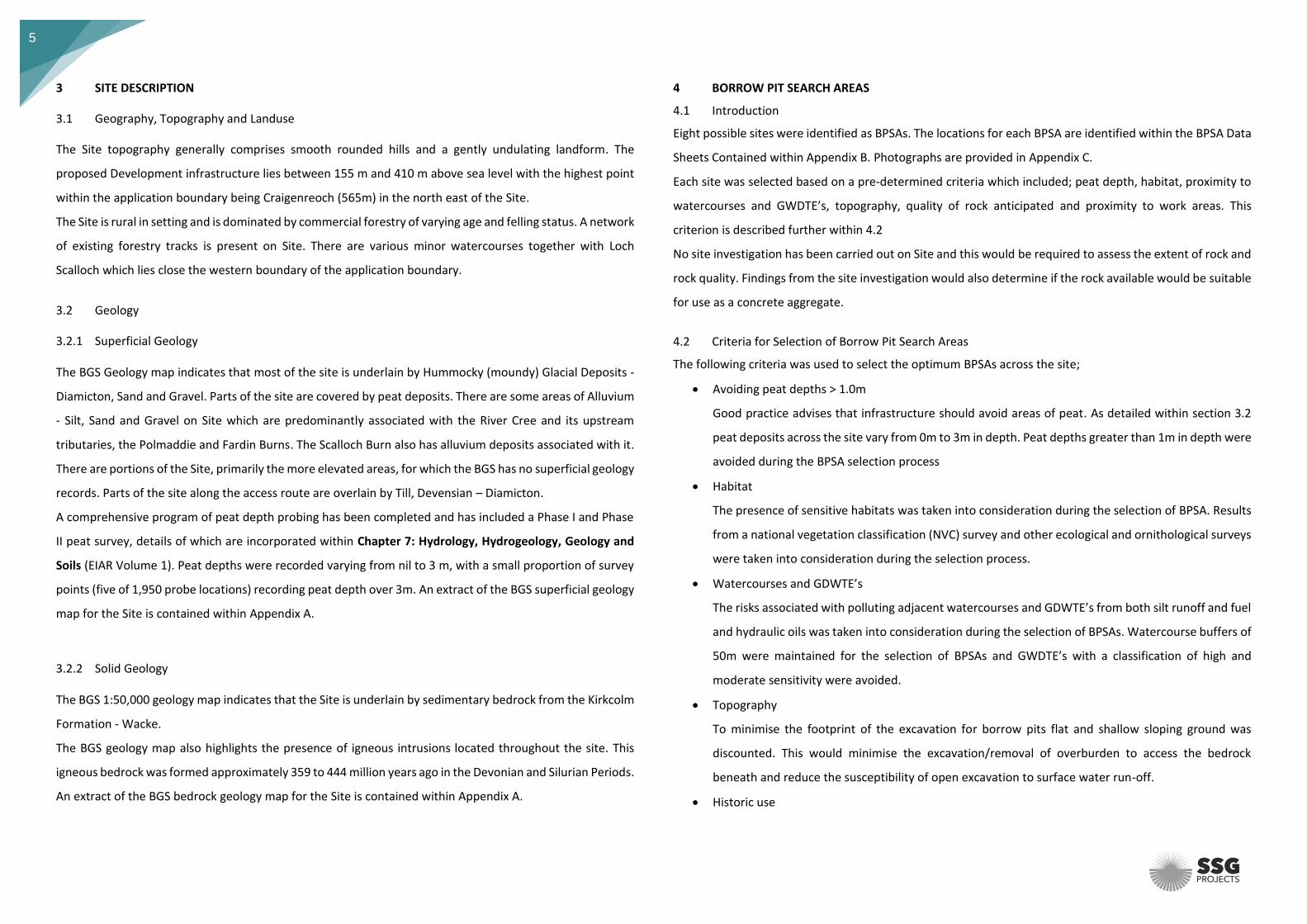
4 BORROW PIT SEARCH AREAS
4.1 Introduction
Eight possible sites were identified as BPSAs. The locations for each BPSA are identified within the BPSA Data
Sheets Contained within Appendix B. Photographs are provided in Appendix C.
Each site was selected based on a pre-determined criteria which included; peat depth, habitat, proximity to
watercourses and GWDTE’s, topography, quality of rock anticipated and proximity to work areas. This
criterion is described further within 4.2
No site investigation has been carried out on Site and this would be required to assess the extent of rock and
rock quality. Findings from the site investigation would also determine if the rock available would be suitable
for use as a concrete aggregate.
4.2 Criteria for Selection of Borrow Pit Search Areas
The following criteria was used to select the optimum BPSAs across the site;
• Avoiding peat depths > 1.0m
Good practice advises that infrastructure should avoid areas of peat. As detailed within section 3.2
peat deposits across the site vary from 0m to 3m in depth. Peat depths greater than 1m in depth were
avoided during the BPSA selection process
• Habitat
The presence of sensitive habitats was taken into consideration during the selection of BPSA. Results
from a national vegetation classification (NVC) survey and other ecological and ornithological surveys
were taken into consideration during the selection process.
• Watercourses and GDWTE’s
The risks associated with polluting adjacent watercourses and GDWTE’s from both silt runoff and fuel
and hydraulic oils was taken into consideration during the selection of BPSAs. Watercourse buffers of
50m were maintained for the selection of BPSAs and GWDTE’s with a classification of high and
moderate sensitivity were avoided.
• Topography
To minimise the footprint of the excavation for borrow pits flat and shallow sloping ground was
discounted. This would minimise the excavation/removal of overburden to access the bedrock
beneath and reduce the susceptibility of open excavation to surface water run-off.
• Historic use

6
Where other selection criteria were met sites used for rock extraction in the past have been favoured.
Many of these were identified on Ordnance Survey maps and their suitability and likely remaining
rock resource was assessed through visual inspection.
• Quality of rock
Visual inspection of exposed rock on site indicate that it is of good quality for construction with no
evidence of weathering and the rock is generally blocky in nature. In addition, the numerous historic
and active borrow pits on site provide further, anecdotal, evidence that the rock is good quality.
Testing will be undertaken as part of the Site Investigation (SI) works to determine the mechanical
properties of the rock.
• Haul Distances
Anticipated haul distances were taken into consideration during the selection process for BPSAs.
Reducing hauls distances between BPSAs and final placement has the following benefits:
o Reduces volume of site traffic/number of haul vehicles and hence air pollution;
o Reduces H&S risk; and
o Reduces tracking of vehicles in periods of wet weather when plant movements should be kept
to a minimum.
4.3 Borrow Pit Search Area Locations
Using the selection criteria summarised in section 4.1 in conjunction with a site visit to undertake visual
inspections resulted in the identification of eight BPSAs. In addition to the BPSAs, an existing borrow pit
utilised by the landowner FLS predominantly used for forest tracks, has been identified to provide a further
source of rock for the proposed Development. The data sheet for each BPSA is contained within Appendix B.
The data sheet provides commentary on the selection criteria as detailed within 4.1.
The selected locations are summarised as follows:
4.3.1 BP A
BP A is in the southern area of the site approximately 1km from the site entrance on the A714. There is
evidence at this location of previous rock extraction as shown in the photograph contained within Appendix
C. There is evidence of good quality rock from historical workings. The topography is gently sloping and
suitable for a borrow pit. The location of this BPSA has also been selected to provide a source of stone for
access track upgrades and the construction of construction compound CC1.
4.3.2 BP B BP B is located on the access track to site, intended to provide a source of stone for its upgrade. There is
evidence at this location of limited historic rock extraction as shown in the photograph contained within
Appendix C. The topography is a small hillock, which lends itself to an efficient borrow pit site.
4.3.3 BP C BPC is located on the lower slopes of Kentie Hill and as such provides favourable topography for being able
to extract large volumes of stone with a relatively compact footprint. Material won from BP C will be used
for access track upgrades and the new section of track along the access route.
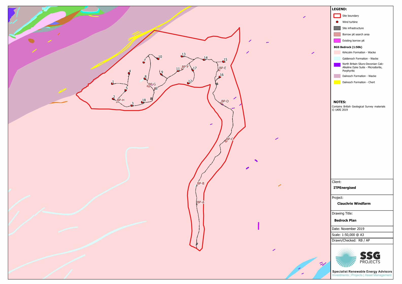
4.3.4 BP D
BP D is located to the north of the new section of access track on the access route. It is directly adjacent to a
borrow pit which was opened by Forest and Land Scotland, the site’s landowners. A visual inspection of the
existing borrow pit clearly identifies that high-quality rock is available at this location. This borrow pit will
provide a source of rock for the new section of access track, together with access track upgrades and material
to construct the temporary construction compound CC2.
4.3.5 BP E
BP E is located on steeply sloping ground which will enable a working face of up to 15m to be achieved by
excavating into the slope, providing an efficient location for rock extraction. The borrow pit’s location has
been selected to minimise haul distances to turbine locations as this borrow pit will chiefly be a source of
material for crane hardstandings and access track construction in the eastern part of the Site.
4.3.6 BP F
BP F is located on gently sloping ground in the central part of site. It provides a source of rock for the
construction of central and eastern site infrastructure. This borrow pit has been refined to avoid nearby areas
of deep peat.

7
4.3.7 BP G
BP G is located on sloping ground in the central part of site. It provides a source of rock for the construction
of central and western site infrastructure. BP G was selected primarily due to its central location and
favourable topography.
4.3.8 BP H BP H is the most westerly borrow pit proposed and has been selected to reduce haul distances to the western
part of the site. It will provide a source of material to construct the control building compound and western
tracks and crane hardstandings.

8
5 CONSTRUCTION REQUIREMENTS
5.1 Rock Volume Requirements
A summary of the indicative volumes of rock required is summarised in Table 5.1.
Table 5.1: Indicative construction stone requirement
Infrastructure Volume (m 3)
Access track (new, cut) 41,187
Access track (new, floating) 20,808
Access track (upgrade) 24,384
Turbine formation 14,476
Crane hardstandings 25,749
Laybys 1,750
Met mast hardstanding 313
Compounds 10,000
Laydown area 5,000
TOTAL 143,666
A total maximum volume of aggregate required from the stone extraction areas would be in the order of
143,666 m3. From the BPSAs, borrow pits have been sized to be able to meet this demand for material, as
detailed in Table 5.2.
Table 5.2: Borrow pit yields
Borrow Pit No. NGR Reference Approximate Dimensions (m)
Yield Volume (m3)*
BP-A 231610, 582191 40 x 90 x 5 8,100
BP-B 231632, 583173 50 x 50 x 8 9,000
BP-C 233146, 585491 70 x 80 x 12 30,240
BP-D 232893, 587465 100 x 60 x 5 13,500
BP-E 232783, 589209 70 x 70 x 15 33,075
BP-F 230958, 589386 60 x 90 x 7 17,010
BP-G 229086, 588354 80 x 80 x 10 28,800
BP-H 227437, 587524 60 x 60 x 5 8,100
TOTAL 147,825
* Yield volume assumes a 90% recovery rate to allow for overburden and the presence of any unsuitable
material.
5.2 Additional Sources of Rock
As shown in section 5.1, the eight proposed borrow pits on site have the capacity to supply all required rock
for the Site’s construction. There are other potential sources of rock which are expected to be available on
site.
Rock is likely to be recovered from turbine excavation works. Each turbine foundation will require an
excavation of approximately 3.5m in depth and a minimum diameter of 37m. This could yield approximately
44,000m3 of additional rock which could be used for infrastructure construction.
An existing FLS borrow pit at NGR 229259,588440 contains a supply of ready-blasted and crushed rock, and
there is potential for this site to be extended.
Should additional sources of rock be utilised, the volume of rock extracted from the borrow pits would be
reduced accordingly.

9
6 CONSTRUCTION METHODS
6.1 Extraction Operations
The requirement to produce various grades of aggregate for different use i.e. bulk fill, track sub-base, track
capping etc would necessitate the use of specialist crushing and grading mobile plant. The operation to
extract stone from the proposed locations is summarised as follows.
6.1.1 Preparation Works
Initial site investigation (SI) works would be undertaken prior to commencement of construction activities.
The SI would determine the quantity and suitability of rock at each of the proposed BPSA locations. Detailed
designs for each of the borrow pit (BP) would be developed following review of the SI results.
Preparatory works associated with each of the BPs would commence at the start of construction for the
proposed development. BPSAs would be worked in accordance with Quarries Regulations 1999.
Information obtained from site visits and peat probing indicate there are limited soils and overburden at each
of the BPSAs as detailed within the BP Data Sheets incorporated within Appendix B. On commencement of
BP development, soils and overburden materials would be stripped from the area and stored in a bund as set
out in Section 6.1.3.
6.1.2 Drainage
Prior to commencement of activities associated with the development of the BPs a detailed drainage system
incorporating adequate mitigation measures would be installed to prevent silt pollution around the
perimeter of each BP. This detail would be incorporated within the Project Construction Method Statement,
Environmental Management Plan and Water Quality Management Plan which are expected to be required
by conditions attached to any consent.
Under the SEPA CAR Licence system the Contractor would be required to obtain a CAR Licence prior to works
commencing. This process would ensure that the mitigation measures proposed meet the required level of
detail expected by SEPA.
Mitigation measures may include (but not be limited to):
• Overburden/loose soil would be stabilised and sheeted (should it be required). Mound heights would
not exceed 3m
• The floor of any BP excavation would be sloped into the hill, to provide attenuation of any
accumulated run off. Sump points would be formed to allow settlement of suspended solids prior to
dispersion by pump to vegetated areas away from local watercourses.
In addition, the following pollution prevention measures would be implemented to minimise any pollution
risk that may arise through the increased surface run-off and sediment mobilisation likely to be generated by
each extraction area:
• Installation of vegetated cut-off drains, peripheral bunds and ditches around the working areas would
intercept uncontaminated surface run-off and divert it around the works ensuring that un-
contaminated surface water does not become laden with silt, and
• Installation of swales to collect runoff placed on the downslope of borrow pits and overburden areas
to collect potentially silty run-off.
• Silt traps, silt fences and/or straw bales would be used in conjunction with swales, if required, to
capture suspended solids generated during the operation of the extraction areas and to minimise the
spread of runoff to the wider environment including the potential GWDTE’s adjacent to BPs.
• Water discharge from sediment ponds would be directed to rough surface vegetation and kept away
from direct discharge to watercourses.
6.1.3 Soils and Overburden Storage
Following the installation of the drainage system, topsoils/peat and overburden would be stripped from the
work area. Materials would be excavated separately and stockpiled adjacent to the BPSA working areas.
Stripped materials would be placed to provide a natural bunded barrier, which would help to prevent public
access to the borrow pit and prevent surface run-off from entering the BPSA from surrounding land.
Temporary fencing would be used to provide an additional physical barrier to prevent unauthorised public
access whilst the BP is active. Additional overburden material not placed in the peripheral bund would be
temporarily stored in an overburden area, located immediately adjacent to the BP working area. All soils
would be stored in accordance with British Standard BS8601:2013 and BS 3882:2015.
As illustrated within the BP Data Sheets contained within Appendix B, it is not anticipated that large quantities
of peat will be encountered. Any peat encountered within the proposed BP working area would be extracted
and stockpiled in a dedicated area agreed with the Environmental Clerk of Works (ECoW). Peat management
would be undertaken in accordance with a Peat Management Plan.
6.1.4 Rock Extraction and Processing On completion of stripping soils and overburden from the footprint of the BP, rock extraction activities would
commence. This is likely to involve a combination of blasting and mechanical crushing.
Where blasting is required it is proposed that a lightweight crawler mounted blast hole drill rig is deployed
with associated compressor. On completion of blasting, stone will be taken to mobile mechanical stone

10
crushers for subsequent processing. The final plant arrangement will be dependent on the phasing of the
BPSA development and the anticipated volumes of rock to be extracted at each location.
Plant located at each of the BPs will be equipped with appropriate spill kits to address fuel/oil spillage should
an incident occur. Fuelling of plant will be undertaken at predetermined locations agreed with the project
ECoW.
7 CONCLUSION
ScottishPower Renewables is proposing an 18 turbine wind farm development near Barhill in South Ayrshire,
Scotland. The development is proposed on an upland area predominantly comprising commercial forestry.
The area is predominantly underlain by sedimentary bedrock from the Kirkcolm Formation – Wacke.
The project will have a requirement for approximately 143,666 m3 of construction stone material mainly for
the construction of access roads, crane hardstandings and construction compounds.
A desktop study and site walkover were carried out to identify potential sources of construction stone and
suitable areas for stone extraction within the development site to provide enough rock material for the
project.
The assessment took into consideration information from recently completed environmental surveys, these
included:
• Peat depth;
• Presence of watercourses;
• Presence of GWDTEs; and
• Habitat sensitivities.
Taking into consideration the existing environment, the geology of the area and the layout of the proposed
development eight BPSAs were identified. Key considerations in the selection process were rock quality and
quantity, sustainability, haul distance, cost effectiveness and potential environmental impacts.
Further investigation is required on all identified BPSAs to determine extent of rock, rock type and suitability
for use as rock fill for the construction of access road, crane platforms and aggregate for use in concrete.
Based on initial calculations it is expected that there will be sufficient material acquired on site to match the
construction requirements.

APPENDIX A: FIGURES Figures:
Superficial Geology
Bedrock
Site boundary
Wind turbine
Site infrastructure
Borrow pit search area
Existing borrow pit
BGS Bedrock (1:50k)
Kirkcolm Formation - Wacke
Galdenoch Formation - Wacke
North Britain Siluro-Devonian Calc-Alkaline Dyke Suite - Microdiorite, Porphyritic
Dalreoch Formation - Wacke
Dalreoch Formation - Chert
Drawn/Checked: RB / AP
Scale: 1:50,000 @ A3
Date: November 2019
Contains British Geological Survey materials© UKRI 2019
Drawing Title:
LEGEND:
Bedrock Plan
Project:
Clauchrie Windfarm
Client:
ITPEnergised
NOTES:

Site boundary
Wind turbine
Site infrastructure
Borrow pit search area
Existing borrow pit
BGS Superficial Deposits (1:50k)
Glacial Deposits - Sand and Gravel
Alluvium - Silt, Sand and Gravel
Till, Devensian – Diamicton
Peat
No available information
Drawn/Checked: RB / AP
Scale: 1:50,000 @ A3
Date: November 2019
Contains British Geological Survey materials© UKRI 2019
Drawing Title:
LEGEND:
Superficial Deposits Plan
Project:
Clauchrie Windfarm
Client:
ITPEnergised
NOTES:

APPENDIX B: DATA SHEETS

Site boundary
Wind turbine
Tracks / hardstandings
Clauchrie laybys
Control building compound
Construction compound
Laydown area
Met mast
Borrow pit search area
FLS borrow pit
Drawn/Checked: RB / AP
Scale: as shown @ A3
Date: November 2019
Drawing Title:
LEGEND:
BPA Data Sheet
Project:
Clauchrie Windfarm
Client:
ITPEnergised
Location | 1:20,000
NOTES:
© Crown copyright and database rights2019 Ordnance Survey 0100031673
Peat probe depth (cm)
0-50
51-100
101-200
201-300
Peat probing indicates peat depth generally less than 1m.
231610, 58219140 x 90 x 58,100
Peat Depths | 1:5,000
Watercourse
Watercourse buffer (50m)
GWDTE sensitivity
High
Moderate
Badger
Otter
Water vole
Water vole buffer (10m)
Ornithology constraint
Cultural heritage constraint
Hard
Soft
EIA surveys indicate proximity to watercourses at this location. Drainage arrangements will require carefulconsideration by contractor. No GWDTEs or other constraints identified.
Location (NGR):Dimensions (m):Yield (m^3):
Constraints | 1:5,000
Rock extracted from this location isproposed to be used for access trackupgrades and construction compoundCC1 to limit haul distances.
Topography | 1:5,000

Site boundary
Wind turbine
Tracks / hardstandings
Clauchrie laybys
Control building compound
Construction compound
Laydown area
Met mast
Borrow pit search area
FLS borrow pit
Drawn/Checked: RB / AP
Scale: as shown @ A3
Date: November 2019
Drawing Title:
LEGEND:
BPB Data Sheet
Project:
Clauchrie Windfarm
Client:
ITPEnergised
Location | 1:20,000
NOTES:
© Crown copyright and database rights2019 Ordnance Survey 0100031673
Peat probe depth (cm)
0-50
51-100
101-200
201-300
Peat probing indicates shallow peat in this location - to a maximum of 0.2m deep.
231632, 58317350 x 50 x 89,000
Peat Depths | 1:5,000
Watercourse
Watercourse buffer (50m)
GWDTE sensitivity
High
Moderate
Badger
Otter
Water vole
Water vole buffer (10m)
Ornithology constraint
Cultural heritage constraint
Hard
Soft
EIA surveys indicate no sensitivities in this location
Location (NGR):Dimensions (m):Yield (m^3):
Constraints | 1:5,000
Rock extracted from this location isproposed to be used for access trackupgrades to limit haul distances.
Topography | 1:5,000

Site boundary
Wind turbine
Tracks / hardstandings
Clauchrie laybys
Control building compound
Construction compound
Laydown area
Met mast
Borrow pit search area
FLS borrow pit
Drawn/Checked: RB / AP
Scale: as shown @ A3
Date: November 2019
Drawing Title:
LEGEND:
BPC Data Sheet
Project:
Clauchrie Windfarm
Client:
ITPEnergised
Location | 1:20,000
NOTES:
© Crown copyright and database rights2019 Ordnance Survey 0100031673
Peat probe depth (cm)
0-50
51-100
101-200
201-300
Peat probing indicates peat depth generally less than 1m.
233146, 58549170 x 80 x 1230,240
Peat Depths | 1:5,000
Watercourse
Watercourse buffer (50m)
GWDTE sensitivity
High
Moderate
Badger
Otter
Water vole
Water vole buffer (10m)
Ornithology constraint
Cultural heritage constraint
Hard
Soft
EIA surveys indicate no sensitivities in this location
Location (NGR):Dimensions (m):Yield (m^3):
Constraints | 1:5,000
Rock extracted from this location isproposed to be used for access trackupgrades and the new section of trackbeyond the River Cree to limit hauldistances.
Topography | 1:5,000
Site boundary
Wind turbine
Tracks / hardstandings
Clauchrie laybys
Control building compound
Construction compound
Laydown area
Met mast
Borrow pit search area
FLS borrow pit
Drawn/Checked: RB / AP
Scale: as shown @ A3
Date: November 2019
Drawing Title:
LEGEND:
BPD Data Sheet
Project:
Clauchrie Windfarm
Client:
ITPEnergised
Location | 1:20,000
NOTES:
© Crown copyright and database rights2019 Ordnance Survey 0100031673
Peat probe depth (cm)
0-50
51-100
101-200
201-300
Peat probing indicates peat depth generally less than 1m.
232893, 587465100 x 60 x 513,500
Peat Depths | 1:5,000
Watercourse
Watercourse buffer (50m)
GWDTE sensitivity
High
Moderate
Badger
Otter
Water vole
Water vole buffer (10m)
Ornithology constraint
Cultural heritage constraint
Hard
Soft
EIA surveys indicate no sensitivities in this location
Location (NGR):Dimensions (m):Yield (m^3):
Constraints | 1:5,000
Rock extracted from this location isproposed to be used for access trackupgrades and for constructioncompound CC2 to limit haul distances.
Topography | 1:5,000
Site boundary
Wind turbine
Tracks / hardstandings
Clauchrie laybys
Control building compound
Construction compound
Laydown area
Met mast
Borrow pit search area
FLS borrow pit
Drawn/Checked: RB / AP
Scale: as shown @ A3
Date: November 2019
Drawing Title:
LEGEND:
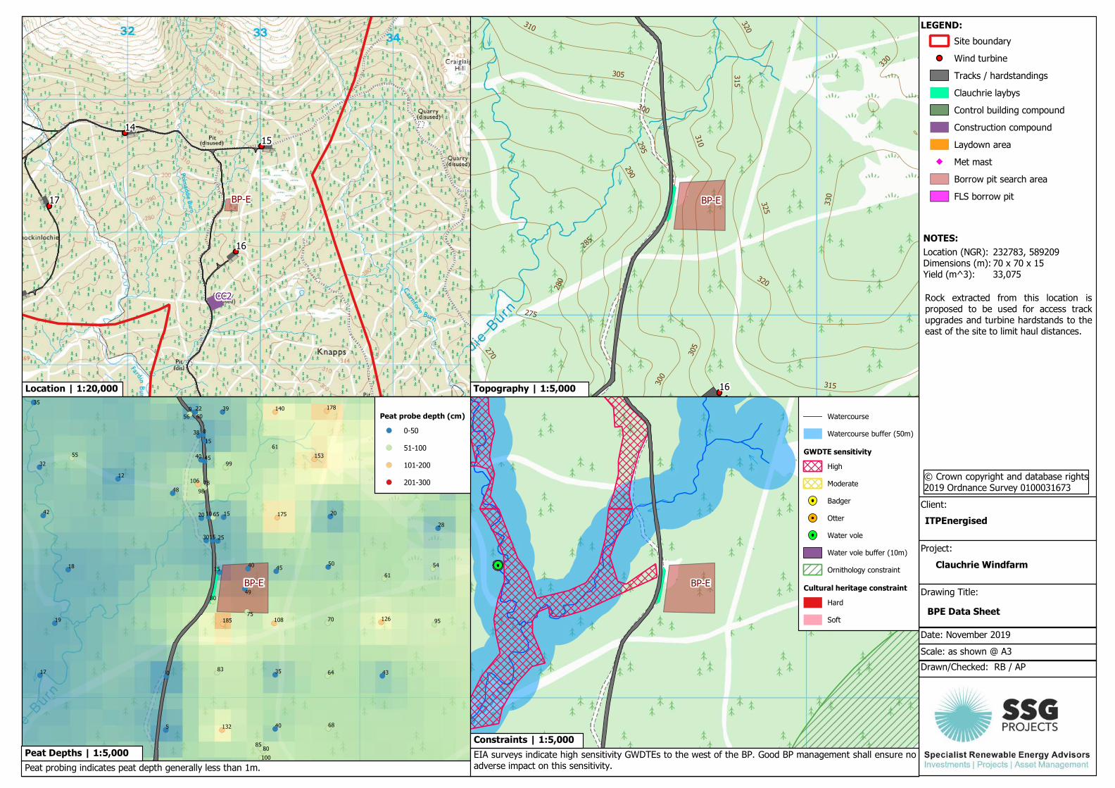
BPE Data Sheet
Project:
Clauchrie Windfarm
Client:
ITPEnergised
Location | 1:20,000
NOTES:
© Crown copyright and database rights2019 Ordnance Survey 0100031673
Peat probe depth (cm)
0-50
51-100
101-200
201-300
Peat probing indicates peat depth generally less than 1m.
232783, 58920970 x 70 x 1533,075
Peat Depths | 1:5,000
Watercourse
Watercourse buffer (50m)
GWDTE sensitivity
High
Moderate
Badger
Otter
Water vole
Water vole buffer (10m)
Ornithology constraint
Cultural heritage constraint
Hard
Soft
EIA surveys indicate high sensitivity GWDTEs to the west of the BP. Good BP management shall ensure noadverse impact on this sensitivity.
Location (NGR):Dimensions (m):Yield (m^3):
Constraints | 1:5,000
Rock extracted from this location isproposed to be used for access trackupgrades and turbine hardstands to theeast of the site to limit haul distances.
Topography | 1:5,000
Site boundary
Wind turbine
Tracks / hardstandings
Clauchrie laybys
Control building compound
Construction compound
Laydown area
Met mast
Borrow pit search area
FLS borrow pit
Drawn/Checked: RB / AP
Scale: as shown @ A3
Date: November 2019
Drawing Title:
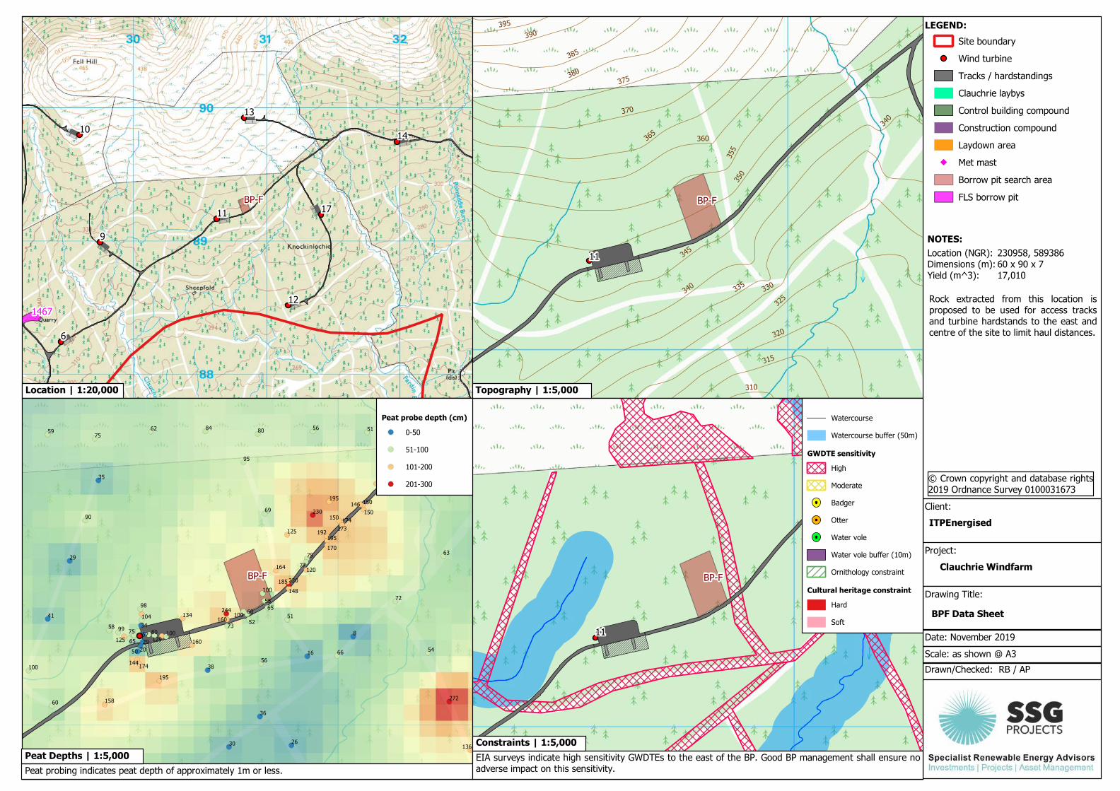
LEGEND:
BPF Data Sheet
Project:
Clauchrie Windfarm
Client:
ITPEnergised
Location | 1:20,000
NOTES:
© Crown copyright and database rights2019 Ordnance Survey 0100031673
Peat probe depth (cm)
0-50
51-100
101-200
201-300
Peat probing indicates peat depth of approximately 1m or less.
230958, 58938660 x 90 x 717,010
Peat Depths | 1:5,000
Watercourse
Watercourse buffer (50m)
GWDTE sensitivity
High
Moderate
Badger
Otter
Water vole
Water vole buffer (10m)
Ornithology constraint
Cultural heritage constraint
Hard
Soft
EIA surveys indicate high sensitivity GWDTEs to the east of the BP. Good BP management shall ensure noadverse impact on this sensitivity.
Location (NGR):Dimensions (m):Yield (m^3):
Constraints | 1:5,000
Rock extracted from this location isproposed to be used for access tracksand turbine hardstands to the east andcentre of the site to limit haul distances.
Topography | 1:5,000
Site boundary
Wind turbine
Tracks / hardstandings
Clauchrie laybys
Control building compound
Construction compound
Laydown area
Met mast
Borrow pit search area
FLS borrow pit
Drawn/Checked: RB / AP
Scale: as shown @ A3
Date: November 2019
Drawing Title:
LEGEND:
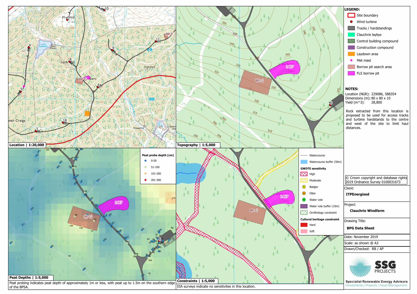
BPG Data Sheet
Project:
Clauchrie Windfarm
Client:
ITPEnergised
Location | 1:20,000
NOTES:
© Crown copyright and database rights2019 Ordnance Survey 0100031673
Peat probe depth (cm)
0-50
51-100
101-200
201-300
Peat probing indicates peat depth of approximately 1m or less, with peat up to 1.5m on the southern edgeof the BPSA.
229086, 58835480 x 80 x 1028,800
Peat Depths | 1:5,000
Watercourse
Watercourse buffer (50m)
GWDTE sensitivity
High
Moderate
Badger
Otter
Water vole
Water vole buffer (10m)
Ornithology constraint
Cultural heritage constraint
Hard
Soft
EIA surveys indicate no sensitivites in this location.
Location (NGR):Dimensions (m):Yield (m^3):
Constraints | 1:5,000
Rock extracted from this location isproposed to be used for access tracksand turbine hardstands to the centreand west of the site to limit hauldistances.
Topography | 1:5,000

Site boundary
Wind turbine
Tracks / hardstandings
Clauchrie laybys
Control building compound
Construction compound
Laydown area
Met mast
Borrow pit search area
FLS borrow pit
Drawn/Checked: RB / AP
Scale: as shown @ A3
Date: November 2019
Drawing Title:
LEGEND:
BPH Data Sheet
Project:
Clauchrie Windfarm
Client:
ITPEnergised
Location | 1:20,000
NOTES:
© Crown copyright and database rights2019 Ordnance Survey 0100031673
Peat probe depth (cm)
0-50
51-100
101-200
201-300
Peat probing indicates peat depths to a maximum of approximately 0.7m
227437, 58752460 x 60 x 58,100
Peat Depths | 1:5,000
Watercourse
Watercourse buffer (50m)
GWDTE sensitivity
High
Moderate
Badger
Otter
Water vole
Water vole buffer (10m)
Ornithology constraint
Cultural heritage constraint
Hard
Soft
EIA surveys indicate no sensitivites in this location.
Location (NGR):Dimensions (m):Yield (m^3):
Constraints | 1:5,000
Rock extracted from this location isproposed to be used for access tracksand turbine hardstands to west of thesite and the control room compound tolimit haul distances.
Topography | 1:5,000

APPENDIX C: PHOTOGRAPHS Introduction This Appendix contains photographs of the Borrow Pit Search Areas. Not all sites were able to be photographed.

Borrow Pit A
BPA is located on the access road. The site has suitable topography for a borrow pit and rock was visible close to the surface.
Borrow Pit B
BPB is located on the access road. The site has previously been used for rock extraction but was observed to have an ample supply of rock remaining. The site has suitable topography for a borrow pit and rock was visible close to the surface.
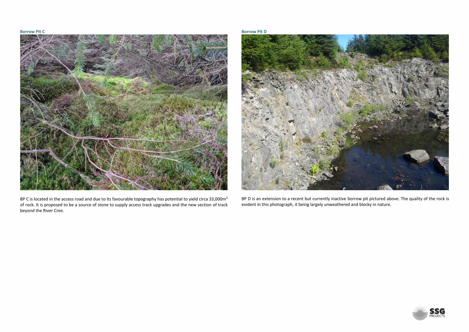
Borrow Pit C
BP C is located in the access road and due to its favourable topography has potential to yield circa 33,000m3 of rock. It is proposed to be a source of stone to supply access track upgrades and the new section of track beyond the River Cree.
Borrow Pit D
BP D is an extension to a recent but currently inactive borrow pit pictured above. The quality of the rock is evident in this photograph, it being largely unweathered and blocky in nature.
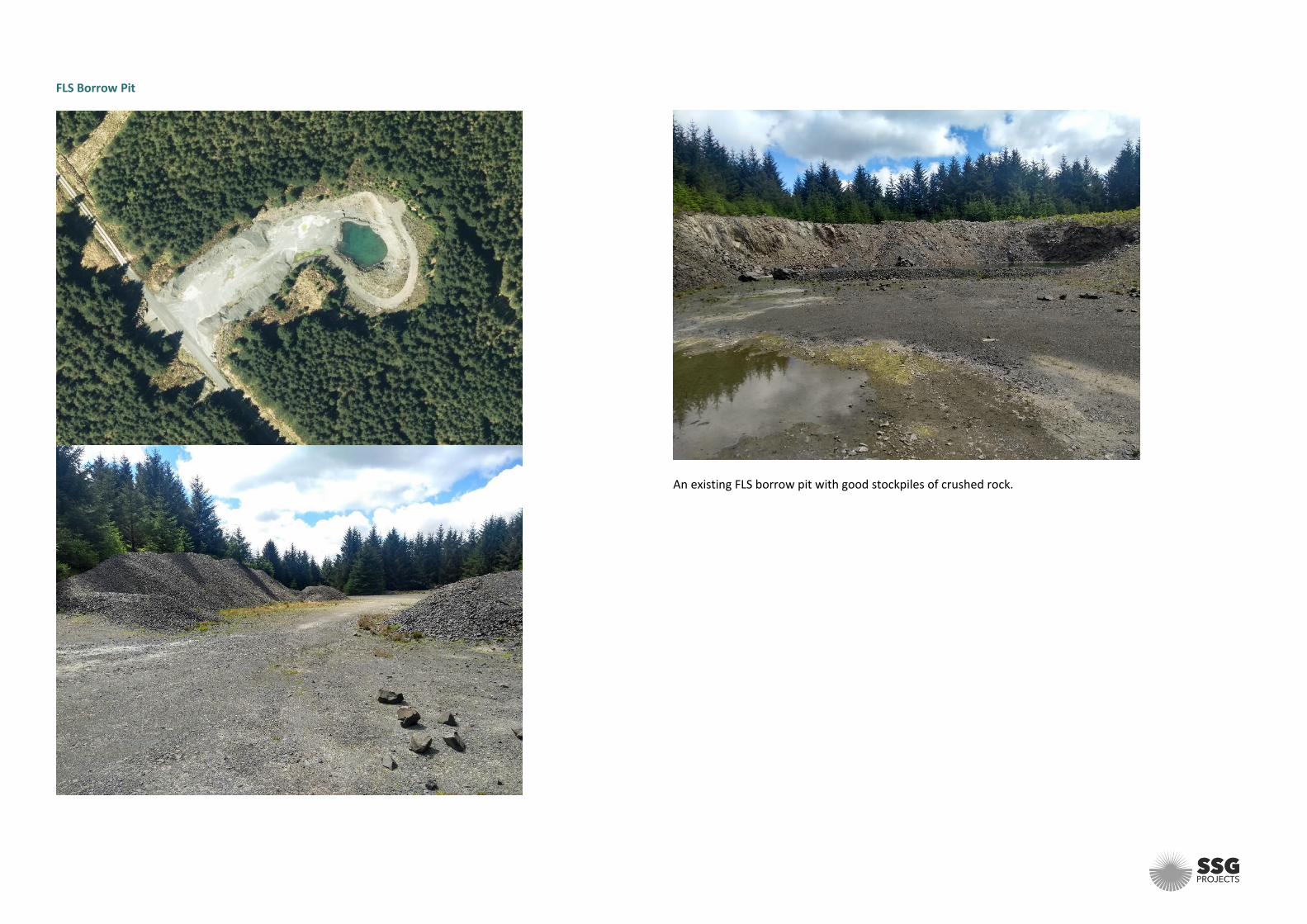
FLS Borrow Pit
An existing FLS borrow pit with good stockpiles of crushed rock.

Sustainable Solutions Group Ltd Systems House (GF2), Rosebank, Livingston EH54 7EG Office: 01506 788500 Web: www.ssgprojects.co.uk ©This Report is the copyright of Sustainable Solutions Group Ltd. Any unauthorised reproduction or usage by any person other that the addressee is strictly prohibited
Related Documents