F1~F97 Boring EZ Bars EZB-HP / EZB-ST / EZB-NB F14 EZ Bar PLUS S-SCLC / C-SCLC F19 EZ Bars (Copying) EZVB F22 System Tip-Bars VNB-S / VNB / VNBT / VNBX-S F30 Twin-Bars TWB / TWBT F36 Tip-Bars PSB-S / PSBT-S F38 2-Edge Tip-Bars HPB / HPBT F39 → will be switched to EZB / PSBT-S CC □□ Insert F40 CP □□ Insert F42 DC □□ Insert F44 JC □□ Insert F48 TC □□ Insert F49 TB / TP □□ Insert F50 VB / VC / VP □□ Insert F54 WB / WP □□ Insert F60 SP □□ Insert F62 TP □□ Insert (without Hole) F63 CN □□ Insert F65 DN □□ Insert F66 TN □□ Insert F66 CC □□ Insert F67 DC □□ Insert F67 Boring Adapter (with coolant hole / anti-vibration damper system) F68 CN □□ Insert F69 DN □□ Insert F71 SN □□ Insert F75 TN □□ Insert F76 WN □□ Insert F78 EZH-CT / EZH-HP / EZH-ST F84 PH F86 SHA / SH / SHC / SJS F86 Product Introduction F2~F5 Identification System / Product Lineup F6~F11 Solid Tip-Bars for Micro Boring F12~F39 Boring Bars for Negative Inserts F69~F80 Boring Bars for Positive Inserts F40~F63 Boring Toolholders for Bearing Machining (Square Shank) F64 AD Bars F65~F68 Boring Bars for Ceramic Tools F81 ~F82 Boring Bars for Solid CBN Tools F83 Sleeves F84~F88 Recommended Cutting Conditions F94~F97 Assembly (AS) List / Former Parts List F89 Parts Compatibility of Lever Lock Toolholders R46 Alternative Toolholder Reference Table for Boring Bar F90~F93 F1

Welcome message from author
This document is posted to help you gain knowledge. Please leave a comment to let me know what you think about it! Share it to your friends and learn new things together.
Transcript
Bor
ing
F
F1~F97
Boring
EZ Bars EZB-HP / EZB-ST / EZB-NB F14EZ Bar PLUS S-SCLC / C-SCLC F19EZ Bars (Copying) EZVB F22System Tip-Bars VNB-S / VNB / VNBT / VNBX-S F30Twin-Bars TWB / TWBT F36Tip-Bars PSB-S / PSBT-S F38
2-Edge Tip-Bars HPB / HPBT F39 → will be switched to EZB / PSBT-S
CC □□ Insert F40CP □□ Insert F42DC □□ Insert F44JC □□ Insert F48TC □□ Insert F49TB / TP □□ Insert F50VB / VC / VP□□ Insert F54WB / WP□□ Insert F60SP □□ Insert F62TP □□ Insert (without Hole) F63
CN □□ Insert F65DN □□ Insert F66TN □□ Insert F66CC □□ Insert F67DC □□ Insert F67Boring Adapter (with coolant hole / anti-vibration damper system) F68
CN □□ Insert F69DN □□ Insert F71SN □□ Insert F75TN □□ Insert F76WN □□ Insert F78
EZH-CT / EZH-HP / EZH-ST F84PH F86SHA / SH / SHC / SJS F86
Product Introduction F2~F5
Identification System / Product Lineup F6~F11
Solid Tip-Bars for Micro Boring F12~F39
Boring Bars for Negative Inserts F69~F80
Boring Bars for Positive Inserts F40~F63
Boring Toolholders for Bearing Machining (Square Shank) F64AD Bars F65~F68
Boring Bars for Ceramic Tools F81~F82
Boring Bars for Solid CBN Tools F83
Sleeves F84~F88
Recommended Cutting Conditions F94~F97
Assembly (AS) List / Former Parts List F89
Parts Compatibility of Lever Lock Toolholders R46
Alternative Toolholder Reference Table for Boring Bar F90~F93
F1
F2 F3
Bor
ing
F
D ynamic Bar
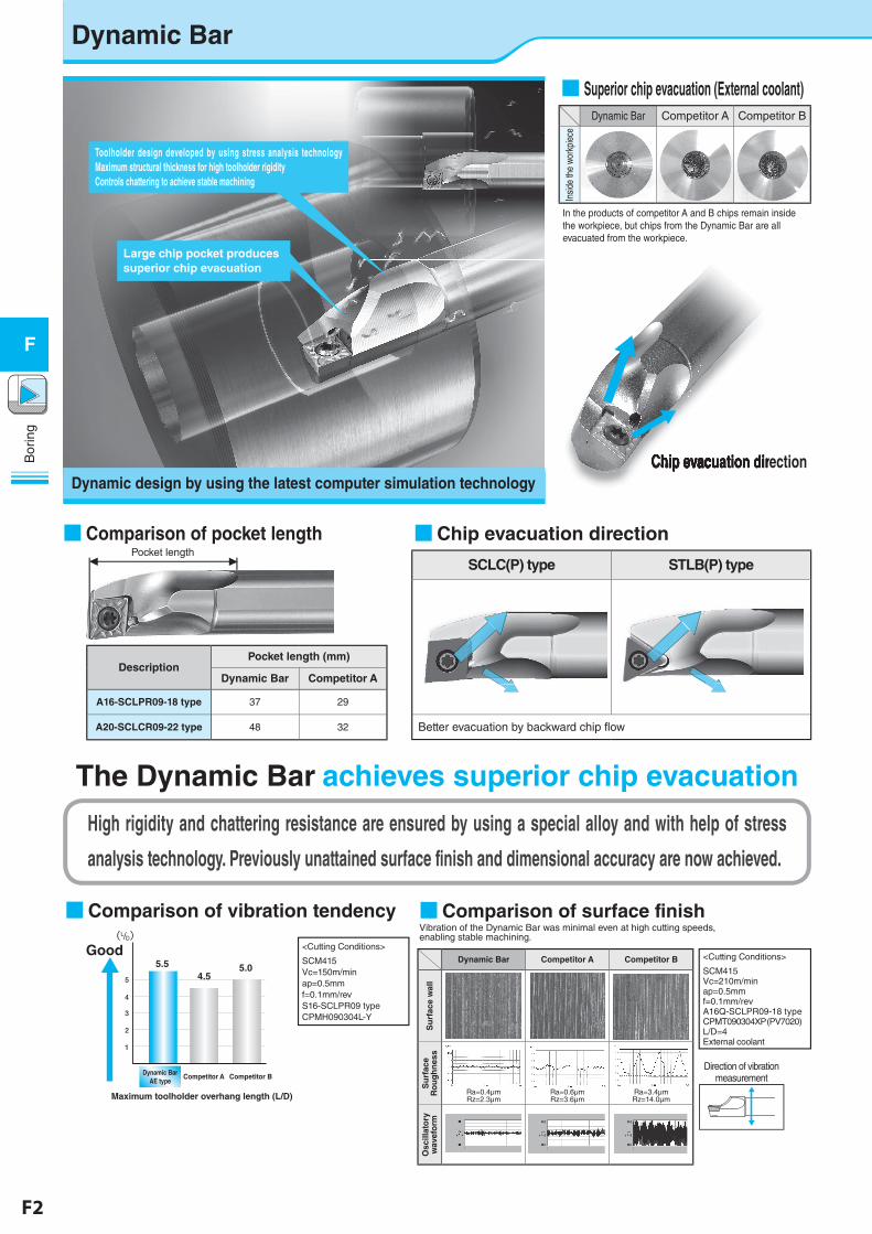
■ Superior chip evacuation (External coolant)Dynamic Bar Competitor A Competitor B
Insid
e th
e wo
rkpi
ece
In the products of competitor A and B chips remain inside the workpiece, but chips from the Dynamic Bar are all evacuated from the workpiece.
Chip evacuation directionChip evacuation directionChip evacuation directionChip evacuation directionChip evacuation direction
■ Comparison of pocket length
DescriptionPocket length (mm)
Dynamic Bar Competitor A
A16-SCLPR09-18 type 37 29
A20-SCLCR09-22 type 48 32
Pocket length
■Chip evacuation direction
SCLC(P) type STLB(P) type
Better evacuation by backward chip flow
■Comparison of vibration tendency
5.54.5
5.0
Good
Competitor A
1
2
3
4
5
Dynamic BarAE type
Competitor B
Maximum toolholder overhang length (L/D)
(L/D)<Cutting Conditions>
SCM415Vc=150m/minap=0.5mm f=0.1mm/revS16-SCLPR09 typeCPMH090304L-Y
The Dynamic Bar achieves superior chip evacuation
High rigidity and chattering resistance are ensured by using a special alloy and with help of stress
analysis technology. Previously unattained surface finish and dimensional accuracy are now achieved.
Toolholder design developed by using stress analysis technology Maximum structural thickness for high toolholder rigidity Controls chattering to achieve stable machining
Large chip pocket produces superior chip evacuation
Dynamic design by using the latest computer simulation technology
■Comparison of surface finishVibration of the Dynamic Bar was minimal even at high cutting speeds, enabling stable machining.
Dynamic Bar Competitor A Competitor B
Su
rfac
e w
all
Su
rfac
e R
ou
gh
nes
s
Ra=0.4µmRz=2.3µm
Ra=0.6µmRz=3.6µm
Ra=3.4µmRz=14.0µm
Osc
illat
ory
w
avef
orm
Direction of vibration measurement
<Cutting Conditions>
SCM415Vc=210m/minap=0.5mmf=0.1mm/revA16Q-SCLPR09-18 typeCPMT090304XP(PV7020)L/D=4External coolant
F2 F3
Bor
ing
F
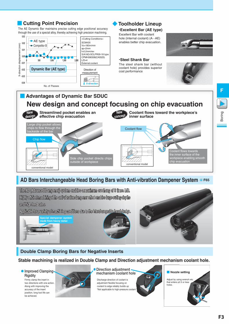
■Cutting Point PrecisionThe AE Dynamic Bar maintains precise cutting edge positional accuracy through the use of a special alloy, thereby achieving high precision machining.
-0.04
-0.03
-0.02
-0.01
0.00
0.01
0.02
0.03
0 500 1,000 1,500 2,000
X-d
irect
ion
disp
lace
men
t (m
m)
AE typeCompetitor B
No. of Passes
Dynamic Bar (AE type)
<Cutting Conditions>
SCM435Vc=180m/minap=2mmf=0.2mm/revS/A16Q-SCLPR09-18 typeCPMH090308(CA5525)L/D=4External coolant
Direction of measurement
X-direction
conventional model
■Advantages of Dynamic Bar SDUC
New design and concept focusing on chip evacuationNew
designStreamlined pocket enables an effective chip evacuation
New concept
Coolant flows toward the workpiece’s inner surface
Large chip pocket allows chips to flow through the backside of the bar
Side chip pocket directs chips outside of workpiece
Coolant flows towards the inner surface of the workpiece enabling smooth chip evacuation
Coolant flow
conventional model
◆ Toolholder Lineup・Excellent Bar (AE type)Excellent Bar with coolant hole (internal coolant) (A···AE) enables better chip evacuation.
・Steel Shank BarThe steel shank bar (without coolant hole) provides superior cost performance
AD Bars Interchangeable Head Boring Bars with Anti-vibration Dampener System
Double Clamp Boring Bars for Negative Inserts
Stable machining is realized in Double Clamp and Direction adjustment mechanism coolant hole.
Chip flow
The AD (Advanced Dampener) system enables a maximum overhang of 6 times L/D.
Highly efficient machining : The anti-vibration dampener effect enables large cutting-depths
and high feed rates.
Applicable for a variety of machining conditions due to the interchangeable head design.Special dampener system made from heavy metal
● Improved Clamping Rigidity
● Direction adjustment mechanism coolant hole
Discharge direction of coolant is adjustment �exible focusing on coolant to edge reliably builds up*Not applicable to high-pressure coolant
Firmly clamp the insert in two directions with one action.Along with improving the accuracy of the insert position, long tool life can be achieved.
■ Nozzle setting
Adjust by using wrench etc. that enters φ2.5 or less holes.
F65
F4 F5
Bor
ing
F
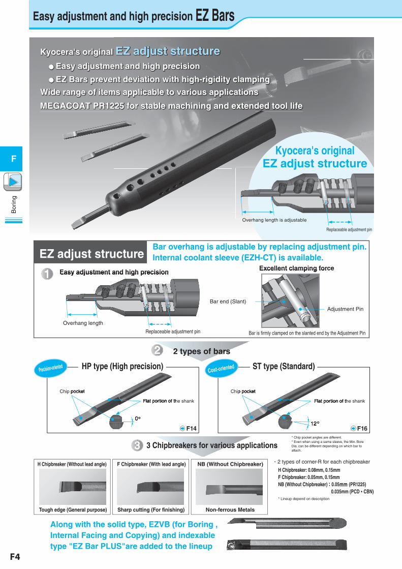
Easy adjustment and high precision EZ Bars
Kyocera's originalEZ adjust structure
Overhang length is adjustable
Replaceable adjustment pin
1
2
3
Easy adjustment and high precisionEasy adjustment and high precision
Overhang length
Replaceable adjustment pin
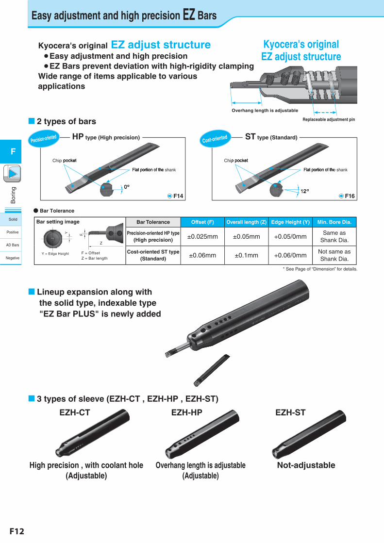
EZ adjust structureBar overhang is adjustable by replacing adjustment pin.Internal coolant sleeve (EZH-CT) is available.
Excellent clamping force
2 types of bars
3 Chipbreakers for various applications
Bar end (Slant)
Chip pocket Chip pocket
Flat portion of the shank Flat portion of the shank
0°12°
Adjustment Pin
Excellent clamping force
Bar is firmly clamped on the slanted end by the Adjustment Pin
Chip pocket
Flat portion of the shank
0°
Chip pocket
Flat portion of the shank
12°
ST type (Standard)
* Chip pocket angles are different.* Even when using a same sleeve, the Min. Bore Dia. can be different depending on which bar to attach.
・2 types of corner-R for each chipbreaker
* Lineup depend on description
H Chipbreaker: 0.08mm, 0.15mmF Chipbreaker: 0.05mm, 0.15mmNB (Without Chipbreaker):0.05mm (PR1225) 0.035mm (PCD・CBN)
Kyocera's original EZ adjust structure ● Easy adjustment and high precision
● EZ Bars prevent deviation with high-rigidity clamping
Wide range of items applicable to various applications
MEGACOAT PR1225 for stable machining and extended tool life
H Chipbreaker (Without lead angle)
Tough edge (General purpose) Sharp cutting (For finishing)
F Chipbreaker (With lead angle)
Non-ferrous Metals
NB (Without Chipbreaker)
Precision-orientedCost-oriented
F14 F16
Along with the solid type, EZVB (for Boring , Internal Facing and Copying) and indexable type "EZ Bar PLUS"are added to the lineup
HP type (High precision)
F4 F5
Bor
ing
F
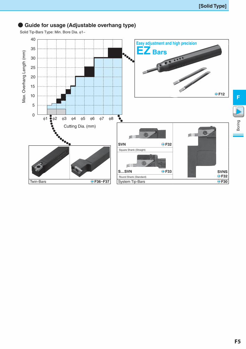
[Solid Type]
Easy adjustment and high precision
EZ Bars
SVN� F32
� SVNS� F32
�Square Shank (Straight)
S…SVN� F33�Round Shank (Standard)
System Tip-Bars� F30Twin-Bars� F36~F37
�● Guide for usage (Adjustable overhang type) Solid Tip-Bars Type: Min. Bore Dia. φ1~
10
5
0
15
20
Cutting Dia. (mm)
25
φ1 φ2 φ3 φ4 φ5 φ6 φ7 φ8
30
35
40
Max
. Ove
rhan
g Le
ngth
(m
m)
F12
F6 F7
Bor
ing
F
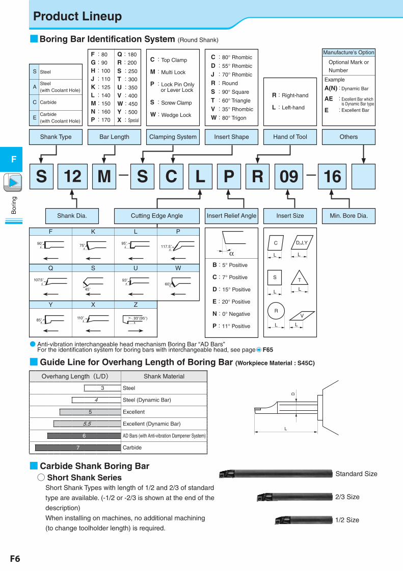
Product Lineup
L
L
φD
D
■Guide Line for Overhang Length of Boring Bar (Workpiece Material : S45C)
○ Short Shank Series■Carbide Shank Boring Bar
Short Shank Types with length of 1/2 and 2/3 of standard
type are available. (-1/2 or -2/3 is shown at the end of the
description)
When installing on machines, no additional machining
(to change toolholder length) is required.
Standard Size
1/2 Size
2/3 Size
● �Anti-vibration interchangeable head mechanism Boring Bar “AD Bars” For the identification system for boring bars with interchangeable head, see page F65
P R 09 16S C LM12S
Y X Z
Q S U W
F K L P
Manufacture's Option
Shank Type
E
C
A
S
Bar Length
F:80
G:90
H:100
J:110
K:125
L:140
M:150
N:160
P:170
Q:180
R:200
S:250
T :300
U:350
V:400
W:450
Y:500
X:Special
C:Top Clamp
M:Multi Lock
P:Lock Pin Only or Lever Lock
S:Screw Clamp
W:Wedge Lock
R:Right-hand
L:Left-hand
Clamping System Insert Shape Hand of Tool Others
Shank Dia. Insert Relief Angle Insert Size Min. Bore Dia.
90° 75° 95°117.5°
107.5°
45°
93°60°
85° 110° 93°(95°)
B:5° Positive
C:7° Positive
D:15° Positive
E:20° Positive
N:0° Negative
P:11° Positive
αD,J,Y
L
L
V
T
L
C
L
L
R
L
S
Steel
Steel�(with Coolant Hole)
Carbide
Carbide(with Coolant Hole)
−−
Optional Mark or
Number
Example
A(N):Dynamic Bar
AE :�Excellent Bar which is Dynamic Bar type
E :Excellent Bar
■Boring Bar Identification System (Round Shank)
Overhang Length(L/D) Shank Material
Steel3
Steel (Dynamic Bar)4
Excellent5
Excellent (Dynamic Bar)5.5
AD Bars (with Anti-vibration Dampener System)6
Carbide7
Cutting Edge Angle
C:80° Rhombic
D:55° Rhombic
J :70° Rhombic
R:Round
S:90° Square
T :60° Triangle
V :35° Rhombic
W:80° Trigon
F6 F7
Bor
ing
F
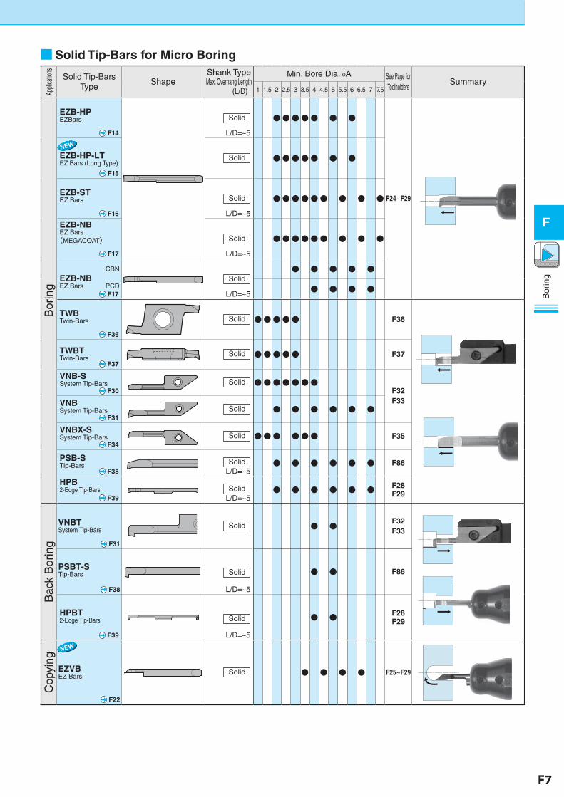
■Solid Tip-Bars for Micro BoringAp
plica
tions
Solid Tip-Bars Type
ShapeShank Type Max. Overhang Length
(L/D)
Min. Bore Dia. φA See Page for Toolholders
Summary1 1.5 2 2.5 3 3.5 4 4.5 5 5.5 6 6.5 7 7.5
Bor
ing
EZB-HPEZBars
F14
Solid
L/D= ~5
●●●●● ● ●
F24~F29
EZB-HP-LTEZ Bars (Long Type)
� F15
Solid ●●●●● ● ●
EZB-STEZ Bars
� F16
Solid
L/D= ~5
●●●●●● ● ● ●
EZB-NBEZ Bars(MEGACOAT)
� F17
Solid
L/D= ~5
●●●●●● ● ● ●
CBN
EZB-NBEZ Bars PCD F17
Solid
L/D= ~5
● ● ● ● ●
● ● ● ●
TWBTwin-Bars
� F36
Solid ●●●●● F36
TWBTTwin-Bars� F37
Solid ●●●●● F37
VNB-SSystem Tip-Bars� F30
Solid ●●●●●●●F32F33VNB
System Tip-Bars� F31
Solid ● ● ● ● ● ●
VNBX-SSystem Tip-Bars� F34
Solid ●●● ●●● F35
PSB-STip-Bars� F38
SolidL/D= ~5
● ● ● ● ● ● F86
HPB2-Edge Tip-Bars� F39
SolidL/D= ~5
● ● ● ● ● ● F28F29
Bac
k B
orin
g
VNBTSystem Tip-Bars
� F31
Solid ● ●F32F33
PSBT-STip-Bars
� F38
Solid
L/D= ~5
● ● F86
HPBT2-Edge Tip-Bars
� F39
Solid
L/D= ~5
● ● F28F29
Cop
ying
EZVBEZ Bars
� F22
Solid ● ● ● ● F25~F29
ファイル名:EZVB(F7)_2.eps
F8 F9
Bor
ing
F
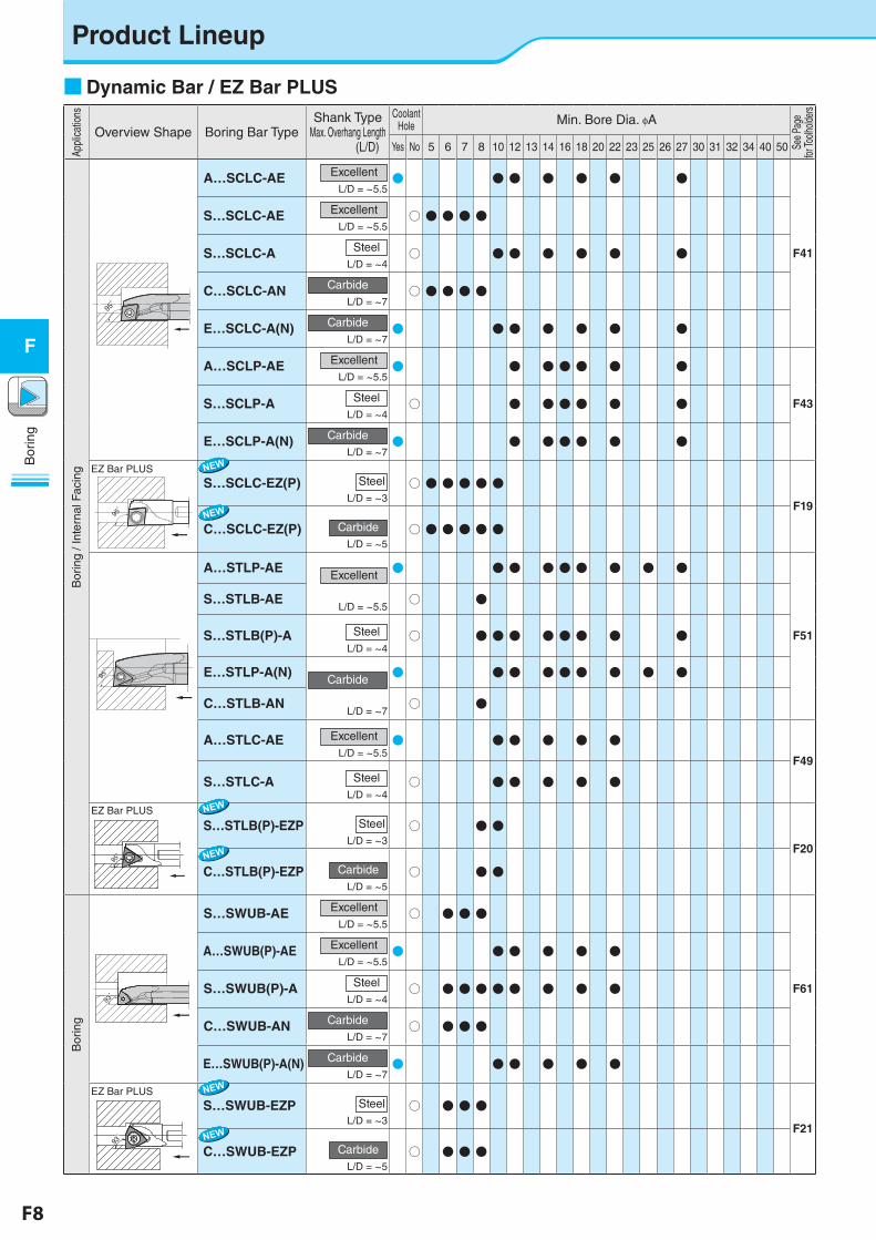
Product LineupAp
plica
tions
Overview Shape Boring Bar TypeShank Type
Max. Overhang Length(L/D)
Coolant Hole Min. Bore Dia. φA
See P
age
for To
olhold
ers
Yes No 5 6 7 8 10 12 13 14 16 18 20 22 23 25 26 27 30 31 32 34 40 50
Bor
ing
/ Int
erna
l Fac
ing
95゚
A…SCLC-AE ExcellentL/D = ~5.5
● ● ● ● ● ● ●
F41
S…SCLC-AE ExcellentL/D = ~5.5
○ ● ● ● ●
S…SCLC-A SteelL/D = ~4
○ ● ● ● ● ● ●
C…SCLC-AN CarbideL/D = ~7
○ ● ● ● ●
E…SCLC-A(N) CarbideL/D = ~7
● ● ● ● ● ● ●
A…SCLP-AE ExcellentL/D = ~5.5
● ● ● ● ● ● ●
F43 S…SCLP-A SteelL/D = ~4
○ ● ● ● ● ● ●
E…SCLP-A(N) CarbideL/D = ~7
● ● ● ● ● ● ●
EZ Bar PLUS
95゚
S…SCLC-EZ(P) SteelL/D = ~3
○ ● ● ● ● ●
F19
C…SCLC-EZ(P) CarbideL/D = ~5
○ ● ● ● ● ●
95゚
A…STLP-AEExcellent
L/D = ~5.5
● ● ● ● ● ● ● ● ●
F51
S…STLB-AE ○ ●
S…STLB(P)-A SteelL/D = ~4
○ ● ● ● ● ● ● ● ●
E…STLP-A(N)Carbide
L/D = ~7
● ● ● ● ● ● ● ● ●
C…STLB-AN ○ ●
A…STLC-AE ExcellentL/D = ~5.5
● ● ● ● ● ●F49
S…STLC-A SteelL/D = ~4
○ ● ● ● ● ●
EZ Bar PLUS
95゚
95゚
最大突出し量L/D = ~3〈S-STL型〉
・本図は右勝手(R)を示す ・右勝手(R)ホルダには左勝手(L)チップが適合します
最大突出し量L/D = ~5〈C-STL型〉
・本図は右勝手(R)を示す ・右勝手(R)ホルダには左勝手(L)チップが適合します
図1 図2
図3 図4
θ
0゚
L4
FφA φ
D
H
L1L2
S θ30
゚
FφA
S
L3
L4
L2
L1
H
φD
θ
0゚
L4
FφA
S
H
L1
L2
φD
θ
5゚FφA
S
L3
L4
L2 H
L1
φD
5゚
95゚95゚
95゚95゚ 95゚95゚
95゚95゚
30゚
30゚ 30゚
S…STLB(P)-EZP SteelL/D = ~3
○ ● ●
F20
C…STLB(P)-EZP CarbideL/D = ~5
○ ● ●
Bor
ing
A-SWUP-AE型 F40
93゚
S…SWUB-AE ExcellentL/D = ~5.5
○ ● ● ●
F61
A…SWUB(P)-AE ExcellentL/D = ~5.5
● ● ● ● ● ●
S…SWUB(P)-A SteelL/D = ~4
○ ● ● ● ● ● ● ● ●
C…SWUB-AN CarbideL/D = ~7
○ ● ● ●
E…SWUB(P)-A(N) CarbideL/D = ~7
● ● ● ● ● ●
EZ Bar PLUS
93゚
93゚
最大突出し量L/D = ~3〈S-SWUB型〉
・本図は右勝手(R)を示す ・右勝手(R)ホルダには左勝手(L)チップが適合します
最大突出し量L/D = ~5〈C-SWUB型〉
・本図は右勝手(R)を示す ・右勝手(R)ホルダには左勝手(L)チップが適合します
図1 図2
θ
0゚
L4
F
L2L1
H
φA φD
F
θ
L4
φA
L1HL2
φD
30゚
0゚
30゚
S…SWUB-EZP SteelL/D = ~3
○ ● ● ●
F21
C…SWUB-EZP CarbideL/D = ~5
○ ● ● ●
■Dynamic Bar / EZ Bar PLUS
F8 F9
Bor
ing
F
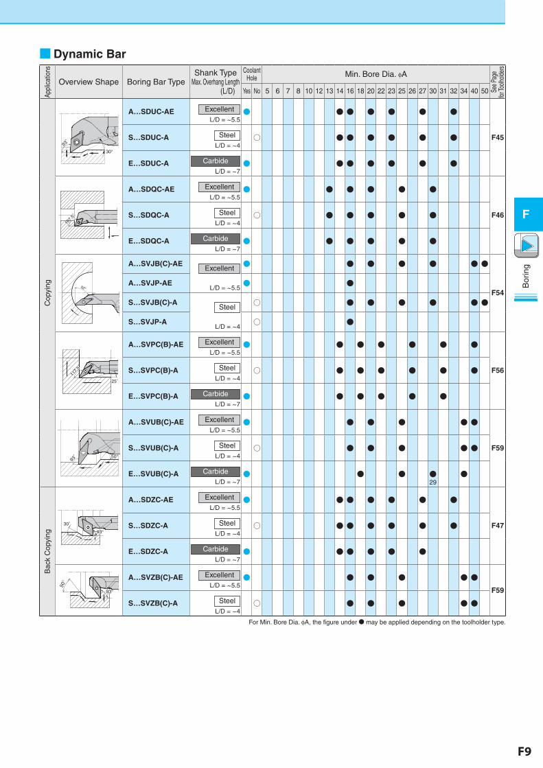
■Dynamic BarAp
plica
tions
Overview Shape Boring Bar TypeShank Type
Max. Overhang Length(L/D)
Coolant Hole Min. Bore Dia. φA
See P
age
for To
olhold
ers
Yes No 5 6 7 8 10 12 13 14 16 18 20 22 23 25 26 27 30 31 32 34 40 50
Cop
ying
30°93゚
A…SDUC-AE ExcellentL/D = ~5.5
● ● ● ● ● ● ●
F45 S…SDUC-A SteelL/D = ~4
○ ● ● ● ● ● ●
E…SDUC-A CarbideL/D = ~7
● ● ● ● ● ● ●
107.
5゚
A…SDQC-AE ExcellentL/D = ~5.5
● ● ● ● ● ●
F46 S…SDQC-A SteelL/D = ~4
○ ● ● ● ● ●
E…SDQC-A CarbideL/D = ~7
● ● ● ● ● ●A-SVJB-AE型 F36
52°
A…SVJB(C)-AEExcellent
L/D = ~5.5
● ● ● ● ● ● ●
F54 A…SVJP-AE ● ●
S…SVJB(C)-ASteel
L/D = ~4
○ ● ● ● ● ● ●
S…SVJP-A ○ ●
A-SVPC-AE型 F36
25゚11
7.5゚
117.
5゚
A…SVPC(B)-AE ExcellentL/D = ~5.5
● ● ● ● ● ● ●
F56 S…SVPC(B)-A SteelL/D = ~4
○ ● ● ● ● ● ●
E…SVPC(B)-A CarbideL/D = ~7
● ● ● ● ● ●A-SVUB-AE型 F38
50°93゚
A…SVUB(C)-AE ExcellentL/D = ~5.5
● ● ● ● ● ●
F59 S…SVUB(C)-A SteelL/D = ~4
○ ● ● ● ● ●
E…SVUB(C)-A CarbideL/D = ~7
● ● ● ●29
●
Bac
k C
opyi
ng
A-SDZC-AE型 F31 左
30°
93°93°
A…SDZC-AE ExcellentL/D = ~5.5
● ● ● ● ● ● ●
F47 S…SDZC-A SteelL/D = ~4
○ ● ● ● ● ● ●
E…SDZC-A CarbideL/D = ~7
● ● ● ● ● ●
50°
93°93°
3°
A…SVZB(C)-AE ExcellentL/D = ~5.5
● ● ● ● ● ●F59
S…SVZB(C)-A SteelL/D = ~4
○ ● ● ● ● ●
For Min. Bore Dia. φA, the figure under N may be applied depending on the toolholder type.
F10 F11
Bor
ing
F
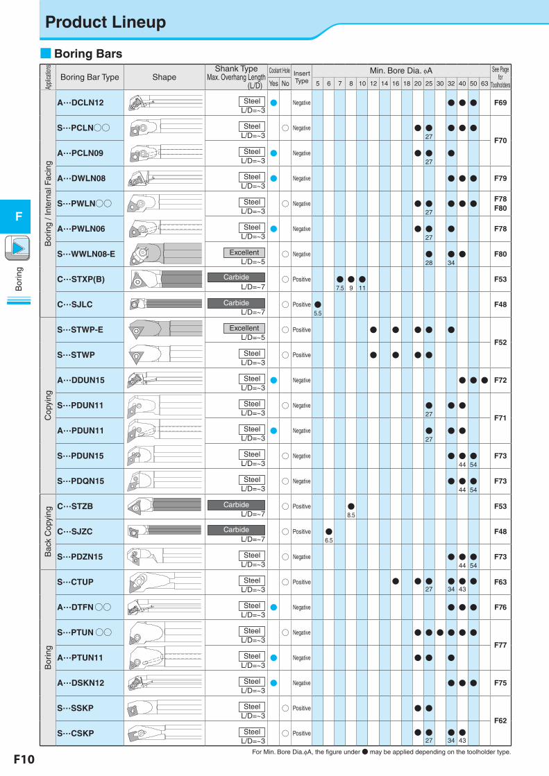
Product Lineup
■Boring BarsAp
plica
tions
Boring Bar Type ShapeShank Type
Max. Overhang Length(L/D)
Coolant Hole Insert Type
Min. Bore Dia. φA See Page for
ToolholdersYes No 5 6 7 8 10 12 14 16 18 20 25 30 32 40 50 63
Bor
ing
/ Int
erna
l Fac
ing
A…DCLN12 SteelL/D= ~3
● Negative ● ● ● F69
S…PCLN○○ SteelL/D= ~3
○ Negative ● ●27
● ● ●F70
A…PCLN09 SteelL/D= ~3
● Negative ● ●27
●
A…DWLN08 SteelL/D= ~3
● Negative ● ● ● F79
S…PWLN○○ SteelL/D= ~3
○ Negative ● ●27
● ● ● F78F80
A…PWLN06 SteelL/D= ~3
● Negative ● ●27
● F78
S…WWLN08-E ExcellentL/D= ~5
○ Negative ●28
●34● F80
C…STXP(B) CarbideL/D= ~7
○ Positive ●7.5●9●11
F53
C…SJLC CarbideL/D= ~7
○ Positive ●5.5
F48
Cop
ying
S…STWP-E ExcellentL/D= ~5
○ Positive ● ● ● ● ●F52
S…STWP SteelL/D= ~3
○ Positive ● ● ● ●
A…DDUN15 SteelL/D= ~3
● Negative ● ● ● F72
S…PDUN11 SteelL/D= ~3
○ Negative ●27
● ●F71
A…PDUN11 SteelL/D= ~3
● Negative ●27
● ●
S…PDUN15 SteelL/D= ~3
○ Negative ● ●44●54
F73
S…PDQN15 SteelL/D= ~3
○ Negative ● ●44●54
F73
Bac
k C
opyi
ng
C…STZB CarbideL/D= ~7
○ Positive ●8.5
F53
C…SJZC CarbideL/D= ~7
○ Positive ●6.5
F48
S…PDZN15 SteelL/D= ~3
○ Negative ● ●44●54
F73
Bor
ing
S…CTUP SteelL/D= ~3
○ Positive ● ● ●27
●34●43● F63
A…DTFN○○ SteelL/D= ~3
● Negative ● ● ● F76
S…PTUN○○ SteelL/D= ~3
○ Negative ● ● ● ● ● ●F77
A…PTUN11 SteelL/D= ~3
● Negative ● ● ●
A…DSKN12 SteelL/D= ~3
● Negative ● ● ● F75
S…SSKP SteelL/D= ~3
○ Positive ● ●F62
S…CSKP SteelL/D= ~3
○ Positive ● ●27
●34●43
For Min. Bore Dia.φA, the figure under● may be applied depending on the toolholder type.
F10 F11
Bor
ing
F
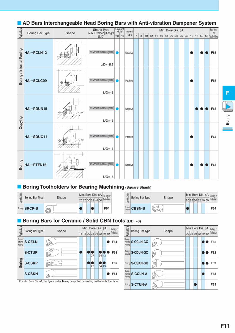
Boring Toolholders for Bearing Machining (Square Shank)
Applic
ations
Boring Bar Type ShapeMin. Bore Dia. φA See Page for
Toolholders20 25 30 32 40 50
Boring SRCP-B ● ● F64
Applic
ations
Boring Bar Type ShapeMin. Bore Dia. φA See Page for
Toolholders16 18 20 25 30 32 40 50
Boring / Internal Facing
S-CELN ● F81
Bor
ing
S-CTUP ● ●●27
●34●43● F63
S-CSKP ●●27
●34●43
F62
S-CSKN ● F81
For Min. Bore Dia. φA, the figure under may be applied depending on the toolholder type.
Boring Bars for Ceramic / Solid CBN Tools (L/D=~3)
Applic
ations
Boring Bar Type ShapeMin. Bore Dia. φA See Page for
Toolholders20 25 30 32 40 50
Boring / Internal Facing
S-CCLN-GX ●● F82
Boring / Copying S-CDUN-GX ●● F82
Boring S-CSKN-GX ●● F82
Boring / Internal Facing
S-CCLN-A ● F83
Boring S-CTUN-A ● F83
Applic
ations
Boring Bar Type ShapeMin. Bore Dia. φA See Page for
Toolholders20 25 30 32 40 50
Round-Chamfering CBSN-B ● F64
AD Bars Interchangeable Head Boring Bars with Anti-vibration Dampener SystemAp
plicatio
ns
Boring Bar Type ShapeShank Type
Max. Overhang Length(L/D)
Coolant Hole Insert
Type
Min. Bore Dia. φA See Page for
ToolholdersYes No 7 8 10 12 14 16 18 20 25 30 32 40 43 50 63
Bor
ing
/ Int
erna
l Fac
ing
HA…PCLN1295゚ Anti-vibration Dampener System
L/D= ~5.5
● Negative ● ● ● F65
HA…SCLC0995゚ Anti-vibration Dampener System
L/D= ~6
● Positive ● F67
Cop
ying
HA…PDUN1527゚93
゚93゚
Anti-vibration Dampener System
L/D= ~6
● Negative ● ● ● F66
HA…SDUC1130゚93
゚93゚
Anti-vibration Dampener System
L/D= ~6
● Positive ● F67
Bor
ing
HA…PTFN1690゚ Anti-vibration Dampener System
L/D= ~6
● Negative ● ● ● F66
F12 F13
Bor
ing
F
Easy adjustment and high precision EZ Bars
Kyocera's original EZ adjust structure
Overhang length is adjustable
Replaceable adjustment pin 2 types of bars
3 types of sleeve (EZH-CT , EZH-HP , EZH-ST)
Lineup expansion along with the solid type, indexable type "EZ Bar PLUS" is newly added
● Bar Tolerance
Kyocera's original EZ adjust structure Easy adjustment and high precision EZ Bars prevent deviation with high-rigidity clampingWide range of items applicable to various applications
Chip pocket
Flat portion of the shank
0°
Chip pocket
Flat portion of the shank
0°
HP type (High precision)Precision-oriented
F14
Chip pocket
Flat portion of the shank
12°
Chip pocket
Flat portion of the shank
12°
ST type (Standard)Cost-oriented
F16
Y
Y = Edge Height
Z
F
F = OffsetZ = Bar length
Bar Tolerance Offset (F) Overall length (Z) Edge Height (Y) Min. Bore Dia.
Precision-oriented HP type (High precision) ±0.025mm ±0.05mm +0.05/0mm
Same as Shank Dia.
Cost-oriented ST type (Standard) ±0.06mm ±0.1mm +0.06/0mm
Not same as Shank Dia.
* See Page of “Dimension” for details.
EZH-HPEZH-CT
Overhang length is adjustable(Adjustable)
High precision , with coolant hole(Adjustable)
EZH-ST
Not-adjustable
Bar setting imageSolid
Positive
AD Bars
Negative
F12 F13
Bor
ing
F
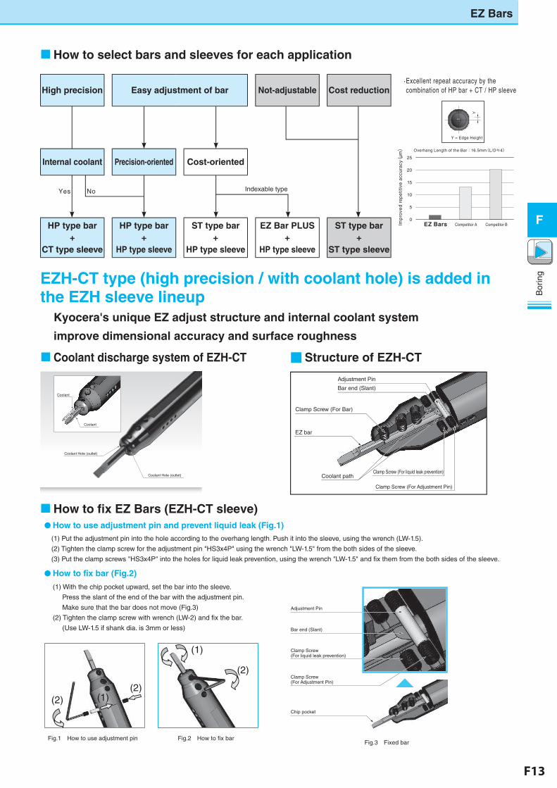
Coolant discharge system of EZH-CT ■Structure of EZH-CT
How to select bars and sleeves for each application
EZH-CT type (high precision / with coolant hole) is added in the EZH sleeve lineup
Kyocera's unique EZ adjust structure and internal coolant system
improve dimensional accuracy and surface roughness
0
5
10
15
20
25
Overhang Length of the Bar:16.5mm(L/D≒4)
Imp
rove
d re
pe
titiv
e a
ccu
racy(
μm)
Competitor BCompetitor AEZ Bars
Y
Y = Edge Height
· Excellent repeat accuracy by the combination of HP bar + CT / HP sleeve
必要 不要
Indexable type
Coolant
Coolant
Coolant Hole (outlet)
Coolant Hole (outlet)
Bar end (Slant)
Adjustment Pin
Clamp Screw (For Bar)
EZ bar
Coolant path
Clamp Screw (For Adjustment Pin)
Clamp Screw (For liquid leak prevention)
Yes No
High precision Easy adjustment of bar Not-adjustable Cost reduction
Internal coolant Precision-oriented Cost-oriented
HP type bar+
CT type sleeve
HP type bar+
HP type sleeve
ST type bar+
HP type sleeve
EZ Bar PLUS+
HP type sleeve
ST type bar+
ST type sleeve
How to fix EZ Bars (EZH-CT sleeve)
(1)
(2)
(2)(2)
(1)
(1) With the chip pocket upward, set the bar into the sleeve.
Press the slant of the end of the bar with the adjustment pin.
Make sure that the bar does not move (Fig.3)
(2) Tighten the clamp screw with wrench (LW-2) and fix the bar.
(Use LW-1.5 if shank dia. is 3mm or less)
●How to use adjustment pin and prevent liquid leak (Fig.1)(1) Put the adjustment pin into the hole according to the overhang length. Push it into the sleeve, using the wrench (LW-1.5).
(2) Tighten the clamp screw for the adjustment pin "HS3x4P" using the wrench "LW-1.5" from the both sides of the sleeve.
(3) Put the clamp screws "HS3x4P" into the holes for liquid leak prevention, using the wrench "LW-1.5" and fix them from the both sides of the sleeve.
●How to fix bar (Fig.2)
Fig.3 Fixed barFig.2 How to fix barFig.1 How to use adjustment pin
Chip pocket
Bar end (Slant)
Clamp Screw (For Adjustment Pin)
Clamp Screw (For liquid leak prevention)
Adjustment Pin
EZ Bars
F14 F15
Bor
ing
F
EZ Bars
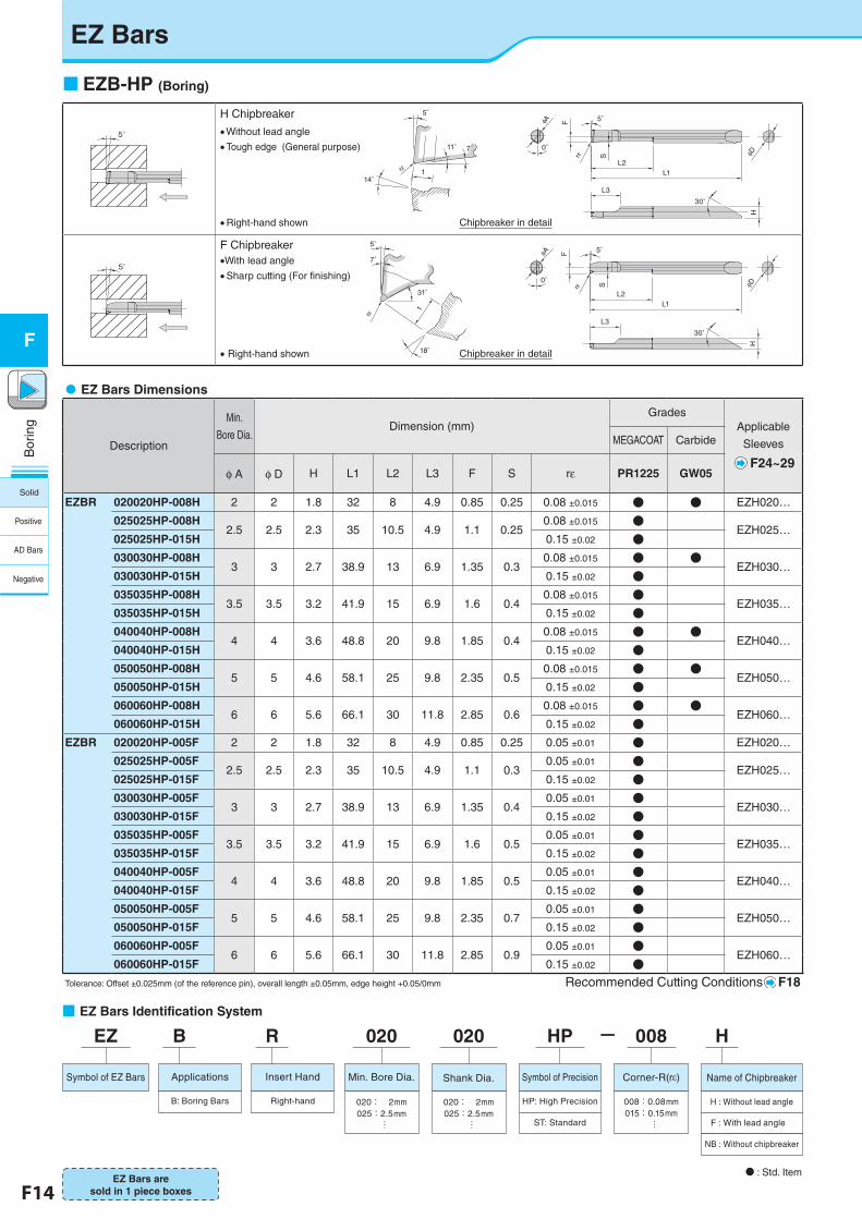
EZB-HP (Boring)
■�EZ Bars Identification System
�EZ Bars Dimensions
Description
Min.
Bore Dia.Dimension (mm)
GradesApplicable
Sleeves
F24~29
MEGACOAT Carbide
φ A φ D H L1 L2 L3 F S rε PR1225 GW05
EZBR 020020HP-008H 2 2 1.8 32 8 4.9 0.85 0.25 0.08 ±0.015 ● ● EZH020…
025025HP-008H2.5 2.5 2.3 35 10.5 4.9 1.1 0.25
0.08 ±0.015 ●EZH025…
025025HP-015H 0.15 ±0.02 ●030030HP-008H
3 3 2.7 38.9 13 6.9 1.35 0.30.08 ±0.015 ● ●
EZH030…030030HP-015H 0.15 ±0.02 ●035035HP-008H
3.5 3.5 3.2 41.9 15 6.9 1.6 0.40.08 ±0.015 ●
EZH035…035035HP-015H 0.15 ±0.02 ●040040HP-008H
4 4 3.6 48.8 20 9.8 1.85 0.40.08 ±0.015 ● ●
EZH040…040040HP-015H 0.15 ±0.02 ●050050HP-008H
5 5 4.6 58.1 25 9.8 2.35 0.50.08 ±0.015 ● ●
EZH050…050050HP-015H 0.15 ±0.02 ●060060HP-008H
6 6 5.6 66.1 30 11.8 2.85 0.60.08 ±0.015 ● ●
EZH060…060060HP-015H 0.15 ±0.02 ●
EZBR 020020HP-005F 2 2 1.8 32 8 4.9 0.85 0.25 0.05 ±0.01 ● EZH020…
025025HP-005F2.5 2.5 2.3 35 10.5 4.9 1.1 0.3
0.05 ±0.01 ●EZH025…
025025HP-015F 0.15 ±0.02 ●030030HP-005F
3 3 2.7 38.9 13 6.9 1.35 0.40.05 ±0.01 ●
EZH030…030030HP-015F 0.15 ±0.02 ●035035HP-005F
3.5 3.5 3.2 41.9 15 6.9 1.6 0.50.05 ±0.01 ●
EZH035…035035HP-015F 0.15 ±0.02 ●040040HP-005F
4 4 3.6 48.8 20 9.8 1.85 0.50.05 ±0.01 ●
EZH040…040040HP-015F 0.15 ±0.02 ●050050HP-005F
5 5 4.6 58.1 25 9.8 2.35 0.70.05 ±0.01 ●
EZH050…050050HP-015F 0.15 ±0.02 ●060060HP-005F
6 6 5.6 66.1 30 11.8 2.85 0.90.05 ±0.01 ●
EZH060…060060HP-015F 0.15 ±0.02 ●
Tolerance: Offset ±0.025mm (of the reference pin), overall length ±0.05mm, edge height +0.05/0mm Recommended Cutting Conditions F18
5°
5°
11° 7°
14°rε 1
5°
L1L2
30°
rε
L3
φDH
S
FφA
0°
5°
31°
18°
7°
5°
rε
1
5°
L1L2
30°
Srε
L3
φDH
φA F
0°
�Right-hand shown Chipbreaker in detail
Chipbreaker in detail
F Chipbreaker
H Chipbreaker Without lead angle�Tough edge (General purpose)
With lead angle�Sharp cutting (For finishing)
� Right-hand shown
N : Std. Item
-EZ
Symbol of EZ Bars
020
Min. Bore Dia.
020: 2mm025:2.5mm
…
B
Applications
B: Boring Bars
R
Insert Hand
Right-hand
020
020: 2mm025:2.5mm
…
Shank Dia.
HP
Symbol of Precision
008
008:0.08mm015:0.15mm
…
Corner-R(rε)
H
Name of Chipbreaker
H : Without lead angle
F : With lead angle
NB : Without chipbreaker
HP: High Precision
ST: Standard
EZ Bars are sold in 1 piece boxes
Solid
Positive
AD Bars
Negative
F14 F15
Bor
ing
F
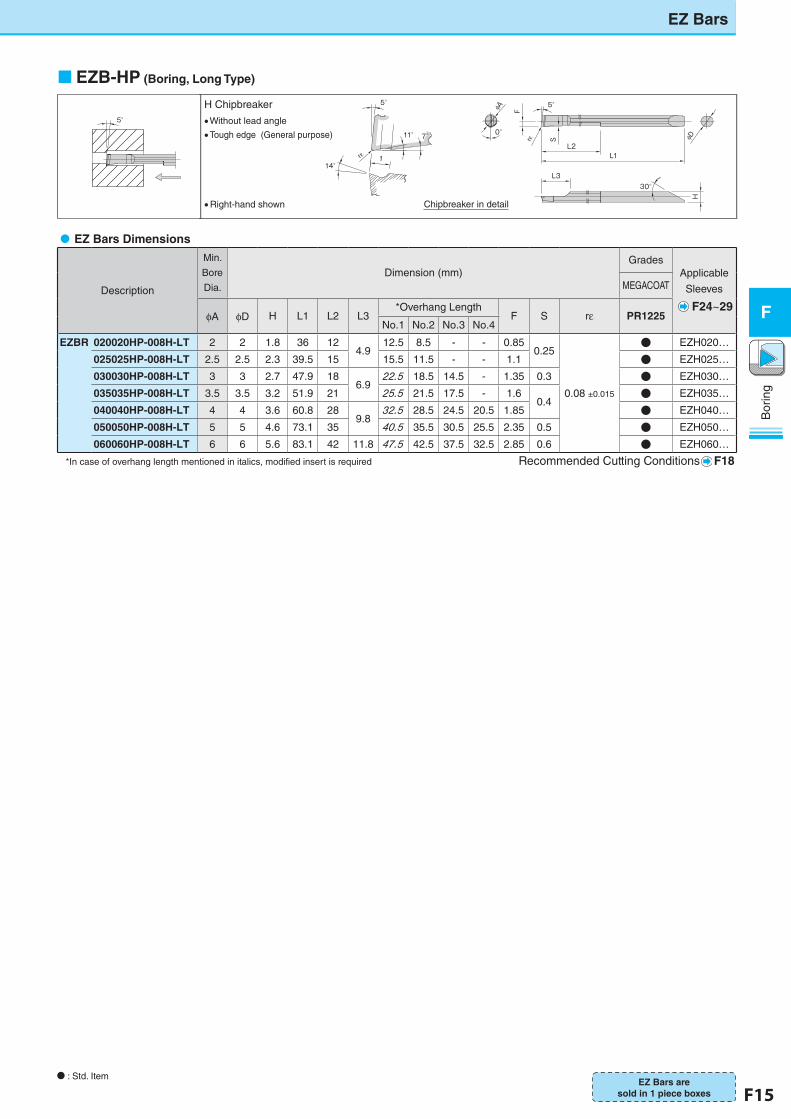
EZB-HP (Boring, Long Type)
�EZ Bars Dimensions
Description
Min.
Bore
Dia.
Dimension (mm)Grades
Applicable
Sleeves
F24~29
MEGACOAT
φA φD H L1 L2 L3*Overhang Length
F S rε PR1225No.1 No.2 No.3 No.4
EZBR 020020HP-008H-LT 2 2 1.8 36 124.9
12.5 8.5 - - 0.850.25
0.08 ±0.015
● EZH020…
025025HP-008H-LT 2.5 2.5 2.3 39.5 15 15.5 11.5 - - 1.1 ● EZH025…
030030HP-008H-LT 3 3 2.7 47.9 186.9
22.5 18.5 14.5 - 1.35 0.3 ● EZH030…
035035HP-008H-LT 3.5 3.5 3.2 51.9 21 25.5 21.5 17.5 - 1.60.4
● EZH035…
040040HP-008H-LT 4 4 3.6 60.8 289.8
32.5 28.5 24.5 20.5 1.85 ● EZH040…
050050HP-008H-LT 5 5 4.6 73.1 35 40.5 35.5 30.5 25.5 2.35 0.5 ● EZH050…
060060HP-008H-LT 6 6 5.6 83.1 42 11.8 47.5 42.5 37.5 32.5 2.85 0.6 ● EZH060…
*In case of overhang length mentioned in italics, modified insert is required Recommended Cutting Conditions F18
EZ Bars
N : Std. ItemEZ Bars are
sold in 1 piece boxes
5°
11° 7°
14°rε 1
5°
ブレーカ詳細
φD
5°
L1L2
Frε S
φA
0°
30°L3
H
内径加工:Hブレーカ
・本図は右勝手(R)を示す
・平行ブレーカ
・刃先強度重視(汎用)
5°
�Right-hand shown Chipbreaker in detail
H Chipbreaker Without lead angle Tough edge (General purpose)
F16 F17
Bor
ing
F
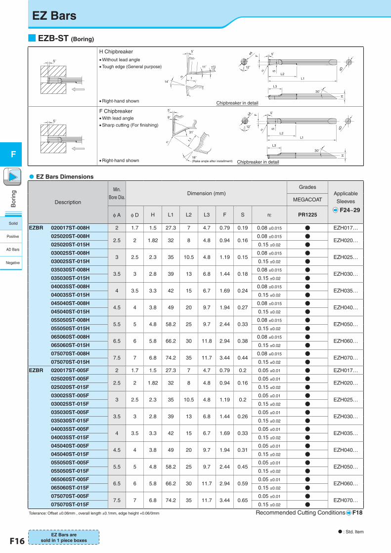
■EZB-ST (Boring)
�EZ Bars Dimensions
Description
Min.
Bore Dia.Dimension (mm)
GradesApplicable
Sleeves
F24~29
MEGACOAT
φ A φ D H L1 L2 L3 F S rε PR1225
EZBR 020017ST-008H 2 1.7 1.5 27.3 7 4.7 0.79 0.19 0.08 ±0.015 ● EZH017…
025020ST-008H2.5 2 1.82 32 8 4.8 0.94 0.16
0.08 ±0.015 ●EZH020…
025020ST-015H 0.15 ±0.02 ●030025ST-008H
3 2.5 2.3 35 10.5 4.8 1.19 0.150.08 ±0.015 ●
EZH025…030025ST-015H 0.15 ±0.02 ●035030ST-008H
3.5 3 2.8 39 13 6.8 1.44 0.180.08 ±0.015 ●
EZH030…035030ST-015H 0.15 ±0.02 ●040035ST-008H
4 3.5 3.3 42 15 6.7 1.69 0.240.08 ±0.015 ●
EZH035…040035ST-015H 0.15 ±0.02 ●045040ST-008H
4.5 4 3.8 49 20 9.7 1.94 0.270.08 ±0.015 ●
EZH040…045040ST-015H 0.15 ±0.02 ●055050ST-008H
5.5 5 4.8 58.2 25 9.7 2.44 0.330.08 ±0.015 ●
EZH050…055050ST-015H 0.15 ±0.02 ●065060ST-008H
6.5 6 5.8 66.2 30 11.8 2.94 0.380.08 ±0.015 ●
EZH060…065060ST-015H 0.15 ±0.02 ●075070ST-008H
7.5 7 6.8 74.2 35 11.7 3.44 0.440.08 ±0.015 ●
EZH070…075070ST-015H 0.15 ±0.02 ●
EZBR 020017ST-005F 2 1.7 1.5 27.3 7 4.7 0.79 0.2 0.05 ±0.01 ● EZH017…
025020ST-005F2.5 2 1.82 32 8 4.8 0.94 0.16
0.05 ±0.01 ●EZH020…
025020ST-015F 0.15 ±0.02 ●030025ST-005F
3 2.5 2.3 35 10.5 4.8 1.19 0.20.05 ±0.01 ●
EZH025…030025ST-015F 0.15 ±0.02 ●035030ST-005F
3.5 3 2.8 39 13 6.8 1.44 0.260.05 ±0.01 ●
EZH030…035030ST-015F 0.15 ±0.02 ●040035ST-005F
4 3.5 3.3 42 15 6.7 1.69 0.330.05 ±0.01 ●
EZH035…040035ST-015F 0.15 ±0.02 ●045040ST-005F
4.5 4 3.8 49 20 9.7 1.94 0.310.05 ±0.01 ●
EZH040…045040ST-015F 0.15 ±0.02 ●055050ST-005F
5.5 5 4.8 58.2 25 9.7 2.44 0.450.05 ±0.01 ●
EZH050…055050ST-015F 0.15 ±0.02 ●065060ST-005F
6.5 6 5.8 66.2 30 11.7 2.94 0.590.05 ±0.01 ●
EZH060…065060ST-015F 0.15 ±0.02 ●075070ST-005F
7.5 7 6.8 74.2 35 11.7 3.44 0.650.05 ±0.01 ●
EZH070…075070ST-015F 0.15 ±0.02 ●
Tolerance: Offset ±0.06mm , overall length ±0.1mm, edge height +0.06/0mm Recommended Cutting Conditions F18
5°
5°
11° 7°
14°rε 1
L2
30°
5°
rε φDH
S
F
L1
L3
φA
12°
5°
30°
S
5°
rε
L3
φDH
F
L2L1
φA
12°
31°
9°
5°
rε 1.1
18°(Rake angle after installment)
�Right-hand shown Chipbreaker in detail
Chipbreaker in detail
F Chipbreaker
�Without lead angle�Tough edge (General purpose)
�With lead angle�Sharp cutting (For finishing)
H Chipbreaker
�Right-hand shown
N : Std. ItemEZ Bars are
sold in 1 piece boxes
EZ Bars
Solid
Positive
AD Bars
Negative
F16 F17
Bor
ing
F
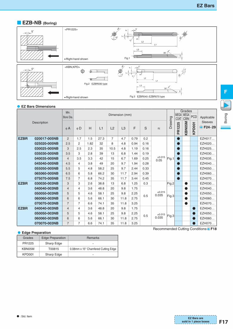
EZB-NB (Boring)
5°
L2
30°
5°
r
D
5°
H
S
F
L1
L3
A
12° 7°
Fig.1
�EZ Bars Dimensions
Description
Min.
Bore Dia.Dimension (mm)
Dra
win
g
Grades
Applicable
Sleeves
F24~29
MEGA COAT
MEGA CBN PCD
φ A φ D H L1 L2 L3 F S rε
PR
1225
KB
N05
M
KP
D0
01
EZBR 020017-005NB 2 1.7 1.5 27.3 7 4.7 0.79 0.2
±0.0150.05 Fig.1
● EZH017…
025020-005NB 2.5 2 1.82 32 8 4.8 0.94 0.16 ● EZH020…
030025-005NB 3 2.5 2.3 35 10.5 4.8 1.19 0.16 ● EZH025…
035030-005NB 3.5 3 2.8 39 13 6.8 1.44 0.19 ● EZH030…
040035-005NB 4 3.5 3.3 42 15 6.7 1.69 0.25 ● EZH035…
045040-005NB 4.5 4 3.8 49 20 9.7 1.94 0.28 ● EZH040…
055050-005NB 5.5 5 4.8 58.2 25 9.7 2.44 0.33 ● EZH050…
065060-005NB 6.5 6 5.8 66.2 30 11.7 2.94 0.39 ● EZH060…
075070-005NB 7.5 7 6.8 74.2 35 11.7 3.44 0.45 ● EZH070…
EZBR 030030-003NB 3 3 2.6 38.8 13 6.8 1.25 0.3
±0.0150.035
Fig.2 ● EZH030…
040040-003NB 4 4 3.6 48.8 20 9.8 1.75
0.5 Fig.3
● EZH040…
050050-003NB 5 5 4.6 58.1 25 9.8 2.25 ● EZH050…
060060-003NB 6 6 5.6 66.1 30 11.8 2.75 ● EZH060…
070070-003NB 7 7 6.6 74.1 35 11.8 3.25 ● EZH070…
EZBR 040040-003NB 4 4 3.6 48.8 20 9.8 1.75
0.5 ±0.0150.035 Fig.3
● EZH040…
050050-003NB 5 5 4.6 58.1 25 9.8 2.25 ● EZH050…
060060-003NB 6 6 5.6 66.1 30 11.8 2.75 ● EZH060…
070070-003NB 7 7 6.6 74.1 35 11.8 3.25 ● EZH070…
� Recommended Cutting Conditions F18
5°
�Right-hand shown
<KBN,KPD>
�Right-hand shown
<PR1225>
30°
H
L3
L1L2
S
rεF 5°
φD
0°
φA
7°
Fig.2 EZBR030 type
Fig.3 EZBR040~EZBR070 type
�Edge PreparationGrades Edge Preparation Remarks
PR1225 Sharp Edge -KBN05M T00815 0.08mm x 15° Chamfered Cutting Edge
KPD001 Sharp Edge -
EZ Bars
N : Std. ItemEZ Bars are
sold in 1 piece boxes
F18 F19
Bor
ing
F
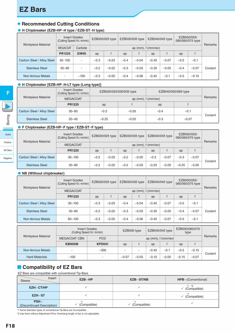
EZ Bars
Recommended Cutting Conditions�H Chipbreaker (EZB-HP··H type / EZB-ST··H type)
Workpiece Material
Insert Grades(Cutting Speed Vc: m/min) EZB020/025 type EZB030/035 type EZB040/045 type EZB050/055/
060/065/075 typeRemarks
MEGACOAT Carbide ap (mm), f (mm/rev)
PR1225 GW05 ap f ap f ap f ap f
Carbon Steel / Alloy Steel 30~100 - ~0.3 ~0.03 ~0.4 ~0.04 ~0.45 ~0.07 ~0.5 ~0.1
CoolantStainless Steel 30~80 - ~0.2 ~0.02 ~0.3 ~0.03 ~0.35 ~0.05 ~0.4 ~0.07
Non-ferrous Metals - ~100 ~0.3 ~0.05 ~0.4 ~0.06 ~0.45 ~0.1 ~0.5 ~0.15
�H Chipbreaker [EZB-HP··H-LT type (Long type)]
Workpiece Material
Insert Grades(Cutting Speed Vc: m/min) EZB020/025/030/035 type EZB040/050/060 type
RemarksMEGACOAT ap (mm), f (mm/rev)
PR1225 ap f ap f
Carbon Steel / Alloy Steel 30~60 ~0.3 ~0.05 ~0.4 ~0.1Coolant
Stainless Steel 20~40 ~0.25 ~0.05 ~0.3 ~0.07
�F Chipbreaker (EZB-HP··F type / EZB-ST··F type)
Workpiece Material
Insert Grades(Cutting Speed Vc: m/min) EZB020/025 type EZB030/035 type EZB040/045 type EZB050/055/
060/065/075 typeRemarks
MEGACOAT ap (mm), f (mm/rev)
PR1225 ap f ap f ap f ap f
Carbon Steel / Alloy Steel 30~100 ~0.2 ~0.03 ~0.2 ~0.05 ~0.3 ~0.07 ~0.3 ~0.07Coolant
Stainless Steel 30~80 ~0.2 ~0.02 ~0.2 ~0.03 ~0.25 ~0.05 ~0.25 ~0.05
NB (Without chipbreaker)
Workpiece Material
Insert Grades(Cutting Speed Vc: m/min) EZB020/025 type EZB030/035 type EZB040/045 type EZB050/055/
060/065/075 typeRemarks
MEGACOAT ap (mm), f (mm/rev)
PR1225 ap f ap f ap f ap f
Carbon Steel / Alloy Steel 30~100 ~0.3 ~0.03 ~0.4 ~0.04 ~0.45 ~0.07 ~0.5 ~0.1
CoolantStainless Steel 30~80 ~0.2 ~0.02 ~0.3 ~0.03 ~0.35 ~0.05 ~0.4 ~0.07
Non-ferrous Metals 60~100 ~0.3 ~0.05 ~0.4 ~0.06 ~0.45 ~0.07 ~0.5 ~0.1
Workpiece Material
Insert Grades(Cutting Speed Vc: m/min) EZB030 type EZB040/045 type EZB050/060/070
typeRemarks
MEGACOAT CBN PCD ap (mm), f (mm/rev)
KBN05M KPD001 ap f ap f ap f
Non-ferrous Metals - ~300 - - ~0.45 ~0.1 ~0.5 ~0.15Coolant
Hard Materials ~100 - ~0.07 ~0.03 ~0.10 ~0.05 ~0.15 ~0.07
Compatibility of EZ BarsEZ Bars are compatible with conventional Tip-Bars.
InsertSleeve EZB···HP EZB···ST/NB HPB···(Conventional)
EZH···CT/HP *1 *2
(Compatible)
EZH···ST *1
(Compatible)
PSH···(Discontinued Description)
*1 (Compatible)
*1 (Compatible)
*1 Some diameter types of conventional Tip-Bars are incompatible.
*2 Use them without Adjustment Pins. Overhang length of bar is not adjustable.
Solid
Positive
AD Bars
Negative
F18 F19
Bor
ing
F
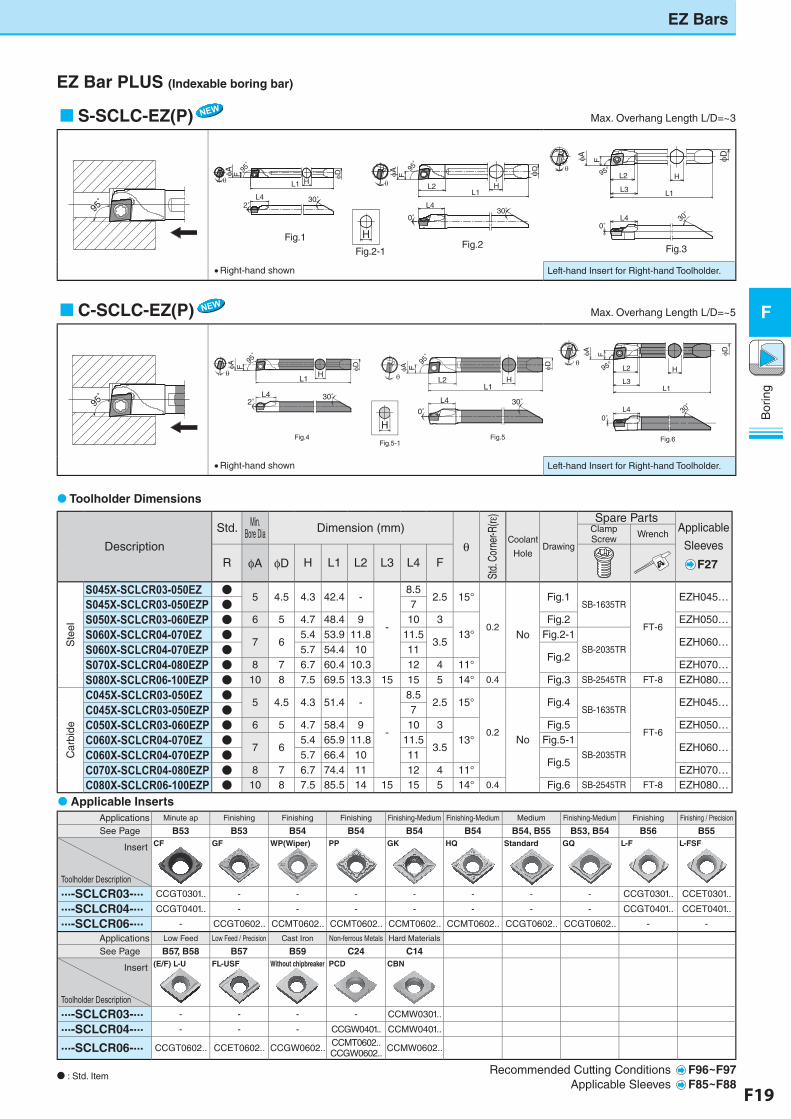
EZ Bars
Toolholder Dimensions
EZ Bar PLUS (Indexable boring bar)
S-SCLC-EZ(P)� Max. Overhang Length L/D=~3
93゚
95゚
�Right-hand shown Left-hand Insert for Right-hand Toolholder.
C-SCLC-EZ(P)� Max. Overhang Length L/D=~5
93゚
95゚
H
0°
L1L2
L4F
θ
θ
φA φD
30°
H
2°
L1
L4
F
θ
φA φD
30°
95゚
95゚95゚
0°
φA
H
L1
30°
95°
F
L3
L4
L2 H
φD
Fig.4 Fig.5 Fig.6Fig.5-1
�Right-hand shown Left-hand Insert for Right-hand Toolholder.
Description
Std. Min. Bore Dia Dimension (mm)
θ
Std.
Corn
er-R
(rε)
Coolant
HoleDrawing
Spare PartsApplicable
Sleeves
F27
Clamp Screw Wrench
R φA φD H L1 L2 L3 L4 F
Ste
el
S045X-SCLCR03-050EZ ●5 4.5 4.3 42.4 -
-
8.52.5 15°
0.2No
Fig.1SB-1635TR
FT-6
EZH045…S045X-SCLCR03-050EZP ● 7
S050X-SCLCR03-060EZP ● 6 5 4.7 48.4 9 10 313°
Fig.2 EZH050…
S060X-SCLCR04-070EZ ●7 6
5.4 53.9 11.8 11.53.5
Fig.2-1SB-2035TR
EZH060…S060X-SCLCR04-070EZP ● 5.7 54.4 10 11Fig.2S070X-SCLCR04-080EZP ● 8 7 6.7 60.4 10.3 12 4 11° EZH070…
S080X-SCLCR06-100EZP ● 10 8 7.5 69.5 13.3 15 15 5 14° 0.4 Fig.3 SB-2545TR FT-8 EZH080…
Car
bide
C045X-SCLCR03-050EZ ●5 4.5 4.3 51.4 -
-
8.52.5 15°
0.2No
Fig.4SB-1635TR
FT-6
EZH045…C045X-SCLCR03-050EZP ● 7
C050X-SCLCR03-060EZP ● 6 5 4.7 58.4 9 10 313°
Fig.5 EZH050…
C060X-SCLCR04-070EZ ●7 6
5.4 65.9 11.8 11.53.5
Fig.5-1SB-2035TR
EZH060…C060X-SCLCR04-070EZP ● 5.7 66.4 10 11Fig.5C070X-SCLCR04-080EZP ● 8 7 6.7 74.4 11 12 4 11° EZH070…
C080X-SCLCR06-100EZP ● 10 8 7.5 85.5 14 15 15 5 14° 0.4 Fig.6 SB-2545TR FT-8 EZH080…
N : Std. Item
H
0°
L1L2
F
θ
θ
φA φD
30°
HL1
L4
F
θ
φA φD
93゚
0°30°
F
L4
L1
HL2
L3
φA
95°
H
φD
L42°30°
95゚
95゚
95゚
Fig.1Fig.2
Fig.2-1 Fig.3
Applications Minute ap Finishing Finishing Finishing Finishing-Medium Finishing-Medium Medium Finishing-Medium Finishing Finishing / Precision
See Page B53 B53 B54 B54 B54 B54 B54, B55 B53, B54 B56 B55
Insert
Toolholder Description
CF GF WP(Wiper) PP GK HQ Standard GQ L-F L-FSF
...-SCLCR03-... CCGT0301.. - - - - - - - CCGT0301.. CCET0301..
...-SCLCR04-... CCGT0401.. - - - - - - - CCGT0401.. CCET0401..
...-SCLCR06-... - CCGT0602.. CCMT0602.. CCMT0602.. CCMT0602.. CCMT0602.. CCGT0602.. CCGT0602.. - -
Applications Low Feed Low Feed / Precision Cast Iron Non-ferrous Metals Hard Materials
See Page B57, B58 B57 B59 C24 C14
Insert
Toolholder Description
(E/F) L-U FL-USF Without chipbreaker PCD CBN
...-SCLCR03-... - - - - CCMW0301..
...-SCLCR04-... - - - CCGW0401.. CCMW0401..
...-SCLCR06-... CCGT0602.. CCET0602.. CCGW0602.. CCMT0602..CCGW0602.. CCMW0602..
Recommended Cutting Conditions F96~F97Applicable Sleeves F85~F88
Applicable Inserts
F20 F21
Bor
ing
F
EZ Bars
Toolholder Dimensions
EZ Bar PLUS (Indexable boring bar)
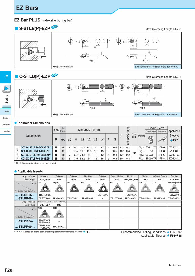
S-STLB(P)-EZP� Max. Overhang Length L/D=~3
95゚
95゚
最大突出し量L/D = ~3〈S-STL型〉
・本図は右勝手(R)を示す ・右勝手(R)ホルダには左勝手(L)チップが適合します
最大突出し量L/D = ~5〈C-STL型〉
・本図は右勝手(R)を示す ・右勝手(R)ホルダには左勝手(L)チップが適合します
Fig.1 Fig.2
Fig.3 Fig.4
θ
0゚
L4
FφA φD
H
L1L2
S θ
30゚
FφA
S
L3
L4
L2
L1
H
φD
θ
0゚
L4
FφA
S
H
L1
L2
φD
θ
5゚FφA
S
L3
L4
L2 H
L1
φD
5゚
95゚95゚
95゚95゚ 95゚95゚
95゚95゚
30゚
30゚ 30゚
Right-hand shown Left-hand Insert for Right-hand Toolholder.
Applicable Inserts
Description
Std. Min. Bore Dia. Dimension (mm)
θ
Std.
Cor
ner-R
(rε)
Coolant Hole Drawing
Spare PartsApplicable
Sleeves
F27
Clamp Screw Wrench
R φA φD H L1 L2 L3 L4 F S
Stee
l S070X-STLBR06-080EZP* ● 8 7 6.7 60.4 10.3 - 12 4 0.4 12° 0.2
No
Fig.1 SB-2035TR FT-6 EZH070…
S080X-STLPR09-100EZP ● 10 8 7.5 69.5 13.3 15 15 5 0.5 10° 0.4 Fig.2 SB-2545TR FT-8 EZH080…
Carb
ide C070X-STLBR06-080EZP* ● 8 7 6.7 74.4 11 - 12 4 0.4 12° 0.2 Fig.3 SB-2035TR FT-6 EZH070…
C080X-STLPR09-100EZP ● 10 8 7.5 85.5 14 15 15 5 0.5 10° 0.4 Fig.4 SB-2545TR FT-8 EZH080…
* TB□□ 060108.. type inserts can not be used.
95゚
95゚
最大突出し量L/D = ~3〈S-STL型〉
・本図は右勝手(R)を示す ・右勝手(R)ホルダには左勝手(L)チップが適合します
最大突出し量L/D = ~5〈C-STL型〉
・本図は右勝手(R)を示す ・右勝手(R)ホルダには左勝手(L)チップが適合します
Fig.1 Fig.2
Fig.3 Fig.4
θ
0゚
L4
FφA φD
H
L1L2
S θ
30゚
FφA
S
L3
L4
L2
L1
H
φD
θ
0゚L4
FφA
S
H
L1
L2
φD
θ
5゚FφA
S
L3
L4
L2 H
L1
φD
5゚
95゚95゚
95゚95゚ 95゚95゚
95゚95゚
30゚
30゚ 30゚
C-STLB(P)-EZP� Max. Overhang Length L/D=~5
95゚
95゚
最大突出し量L/D = ~3〈S-STL型〉
・本図は右勝手(R)を示す ・右勝手(R)ホルダには左勝手(L)チップが適合します
最大突出し量L/D = ~5〈C-STL型〉
・本図は右勝手(R)を示す ・右勝手(R)ホルダには左勝手(L)チップが適合します
Fig.1 Fig.2
Fig.3 Fig.4
θ
0゚
L4
FφA φD
H
L1L2
S θ
30゚
FφA
S
L3
L4
L2
L1
H
φD
θ
0゚
L4
FφA
S
H
L1
L2
φD
θ
5゚FφA
S
L3
L4
L2 H
L1
φD
5゚
95゚95゚
95゚95゚ 95゚95゚
95゚95゚
30゚
30゚ 30゚
95゚
95゚
最大突出し量L/D = ~3〈S-STL型〉
・本図は右勝手(R)を示す ・右勝手(R)ホルダには左勝手(L)チップが適合します
最大突出し量L/D = ~5〈C-STL型〉
・本図は右勝手(R)を示す ・右勝手(R)ホルダには左勝手(L)チップが適合します
Fig.1 Fig.2
Fig.3 Fig.4
θ
0゚
L4
FφA φD
H
L1L2
S θ
30゚
FφA
S
L3
L4
L2
L1
H
φD
θ
0゚
L4
FφA
S
H
L1
L2
φD
θ
5゚FφA
S
L3
L4
L2 H
L1
φD
5゚
95゚95゚
95゚95゚ 95゚95゚
95゚95゚
30゚
30゚ 30゚
Right-hand shown Left-hand Insert for Right-hand Toolholder.
N : Std. Item
Applications Minute ap *Finishing Finishing Finishing Finishing Finishing-Medium Finishing Medium Soft Steel / Finishing Cast Iron
See Page B75, B79 B79 B79 B79 B75 B80 B75, B80, B81 B82 B80 B75, B84
Insert
Toolholder Description
CF (Wiper) PP GP DP HQ L L-H XP Without chipbreaker
...-STLBR06-... TBGT0601.. – – – TBMT0601.. – TBGT0601.. – – TBGW0601..
...-STLPR09-... TPGT0902.. TPMX0902.. TPMT0902.. TPMT0902.. – TPMT0902.. TPGH0902.. TPGH0902.. TPMT0902.. TPGB0902..
Applications Non-ferrous Metals Hard Materials
See Page C26~C27 C16
Insert
Toolholder Description
PCD CBN
...-STLBR06-... TBMT0601.. TBGW0601.. –
...-STLPR09-... TPMH0902.. TPGB0902.. TPGB0902..
Recommended Cutting Conditions F96~F97Applicable Sleeves F85~F88
* For WP chipbreaker, cutting edge offsets or program corrections are required. F94
Solid
Positive
AD Bars
Negative
F20 F21
Bor
ing
F
EZ Bars
●�Toolholder Dimensions
EZ Bar PLUS (Indexable boring bar)
● Applicable Inserts
Description
Std. Min. Bore Dia. Dimension (mm)
θ
Std
. Cor
ner-R
(rε)
Coolant
HoleDrawing
Spare PartsApplicable
Sleeves
F27
Clamp Screw Wrench
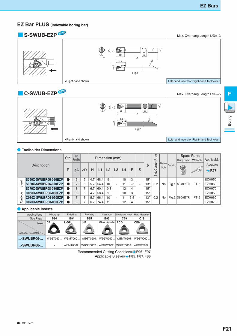
R φA φD H L1 L2 L3 L4 F S
Ste
el
S050X-SWUBR06-060EZP ● 6 5 4.7 48.4 9-
10 3-
15°0.2 No Fig.1 SB-2035TR FT-6
EZH050…
S060X-SWUBR06-070EZP ● 7 6 5.7 54.4 10 11 3.5 13° EZH060…
S070X-SWUBR08-080EZP ● 8 7 6.7 60.4 10.3 12 4 15° EZH070…
Car
bide C050X-SWUBR06-060EZP ● 6 5 4.7 58.4 9
-10 3
-15°
0.2 No Fig.2 SB-2035TR FT-6EZH050…
C060X-SWUBR06-070EZP ● 7 6 5.7 66.4 10 11 3.5 13° EZH060…
C070X-SWUBR08-080EZP ● 8 7 6.7 74.4 11 12 4 15° EZH070…
■S-SWUB-EZP� Max. Overhang Length L/D=~3
93゚
93゚
Max. Overhang Length L/D = ~3〈S-SWUB-EZP〉
・ Right-hand shown
・ Left-hand Insert for Right-hand Toolholder.
Max. Overhang Length L/D = ~5〈C-SWUB-EZP〉
・ Right-hand shown ・ Left-hand Insert for Right-hand Toolholder.
Fig.1 Fig.2θ
0゚
L4
F
L2L1
H
φA φD F
θ
L4
φA
L1HL2
φD
30゚
0゚
30゚
Right-hand shown Left-hand Insert for Right-hand Toolholder.
93゚
93゚
Max. Overhang Length L/D = ~3〈S-SWUB-EZP〉
・ Right-hand shown
・ Left-hand Insert for Right-hand Toolholder.
Max. Overhang Length L/D = ~5〈C-SWUB-EZP〉
・ Right-hand shown ・ Left-hand Insert for Right-hand Toolholder.
Fig.1 Fig.2
θ
0゚
L4
F
L2L1
H
φA φD F
θ
L4
φA
L1HL2
φD
30゚
0゚
30゚
■C-SWUB-EZP� Max. Overhang Length L/D=~5
93゚
93゚
Max. Overhang Length L/D = ~3〈S-SWUB-EZP〉
・ Right-hand shown
・ Left-hand Insert for Right-hand Toolholder.
Max. Overhang Length L/D = ~5〈C-SWUB-EZP〉
・ Right-hand shown ・ Left-hand Insert for Right-hand Toolholder.
Fig.1 Fig.2
θ
0゚
L4
F
L2L1
H
φA φD F
θ
L4
φA
L1HL2
φD
30゚
0゚
30゚
Right-hand shown Left-hand Insert for Right-hand Toolholder.
93゚
93゚
Max. Overhang Length L/D = ~3〈S-SWUB-EZP〉
・ Right-hand shown
・ Left-hand Insert for Right-hand Toolholder.
Max. Overhang Length L/D = ~5〈C-SWUB-EZP〉
・ Right-hand shown ・ Left-hand Insert for Right-hand Toolholder.
Fig.1 Fig.2
θ
0゚
L4
F
L2L1
H
φA φD F
θ
L4
φA
L1HL2
φD
30゚0゚
30゚
● : Std. Item
Recommended Cutting Conditions F96~F97Applicable Sleeves F85, F87, F88
Applications Minute ap Finishing Finishing Cast Iron Non-ferrous Metals Hard Materials
See Page B94 B94 B95 B95 C29 C18
Insert
Toolholder Description
CF L-DP L-F Without chipbreaker PCD CBN
...-SWUBR06-... WBGT0601.. WBMT0601.. WBGT0601.. WBGW0601.. WBMT0601.. WBGW0601..
...-SWUBR08-... - WBMT0802.. WBGT0802.. WBGW0802.. WBMT0802.. WBGW0802..
F22 F23
Bor
ing
F
EZ Bars
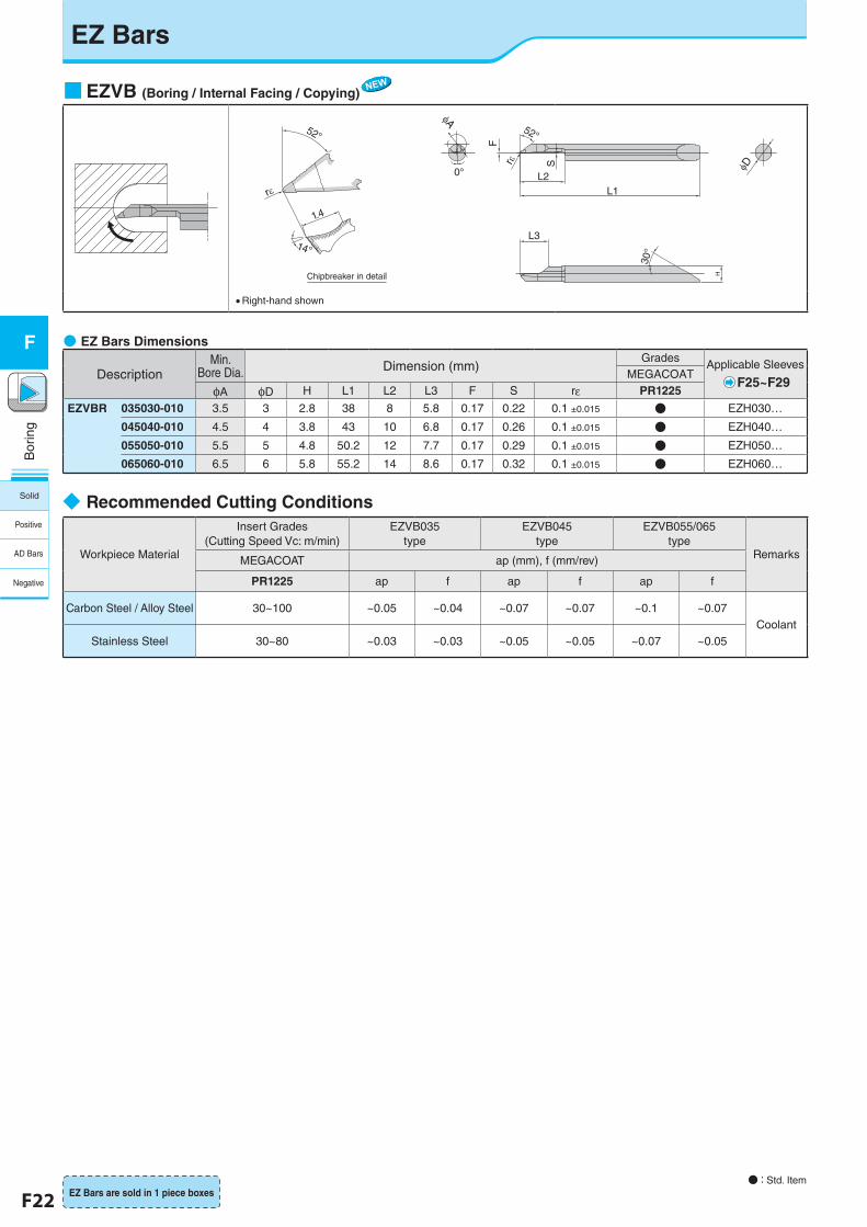
■EZVB (Boring / Internal Facing / Copying)
rε
52°
φA
φD
1.4
L3
0°
30°
H
L1
rε
L2
S
F
52°
14°
Chipbreaker in detail
�Right-hand shown
●�EZ Bars Dimensions
DescriptionMin.
Bore Dia. Dimension (mm)Grades Applicable Sleeves
F25~F29MEGACOAT
φA φD H L1 L2 L3 F S rε PR1225
EZVBR 035030-010 3.5 3 2.8 38 8 5.8 0.17 0.22 0.1 ±0.015 ● EZH030…
045040-010 4.5 4 3.8 43 10 6.8 0.17 0.26 0.1 ±0.015 ● EZH040…
055050-010 5.5 5 4.8 50.2 12 7.7 0.17 0.29 0.1 ±0.015 ● EZH050…
065060-010 6.5 6 5.8 55.2 14 8.6 0.17 0.32 0.1 ±0.015 ● EZH060…
◆�Recommended Cutting Conditions
Workpiece Material
Insert Grades(Cutting Speed Vc: m/min)
EZVB035 type
EZVB045 type
EZVB055/065 type
RemarksMEGACOAT ap (mm), f (mm/rev)
PR1225 ap f ap f ap f
Carbon Steel / Alloy Steel 30~100 ~0.05 ~0.04 ~0.07 ~0.07 ~0.1 ~0.07Coolant
Stainless Steel 30~80 ~0.03 ~0.03 ~0.05 ~0.05 ~0.07 ~0.05
● : Std. ItemEZ Bars are sold in 1 piece boxes
Solid
Positive
AD Bars
Negative
F22 F23
Bor
ing
F
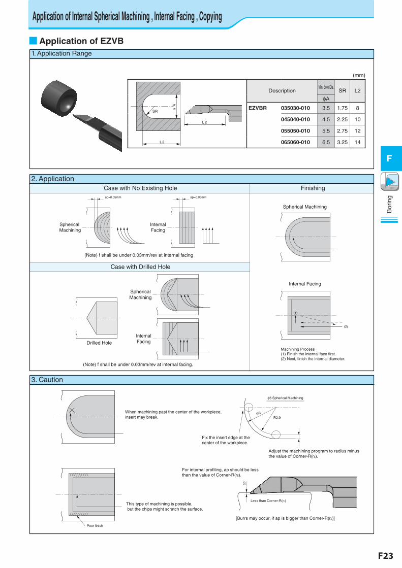
1. Application Range
EZ Bar
■Application of EZVB
2. ApplicationCase with No Existing Hole Finishing
Case with Drilled Hole
ap=0.05mm ap=0.05mm
Spherical Machining
InternalFacing
Spherical Machining
Internal Facing
(1)
(2)
Machining Process(1) Finish the internal face first.(2) Next, finish the internal diameter.
SphericalMachining
Drilled HoleInternalFacing
3. Caution
When machining past the center of the workpiece, insert may break.
Poor finish
This type of machining is possible, but the chips might scratch the surface.
6 Spherical Machining
R3R2.9
Fix the insert edge at the center of the workpiece.
Adjust the machining program to radius minus the value of Corner-R(r ).
ap
Less than Corner-R(r )
[Burrs may occur, if ap is bigger than Corner-R(r )]
For internal profiling, ap should be less than the value of Corner-R(r ).
(Note) f shall be under 0.03mm/rev at internal facing
(Note) f shall be under 0.03mm/rev at internal facing.
Application of Internal Spherical Machining , Internal Facing , Copying
(mm)
L 2
L 2
φ A
SR
DescriptionMin. Bore Dia.
SR L2
φA
EZVBR 035030-010 3.5 1.75 8
045040-010 4.5 2.25 10
055050-010 5.5 2.75 12
065060-010 6.5 3.25 14
F24 F25
Bor
ing
F
EZ Bars
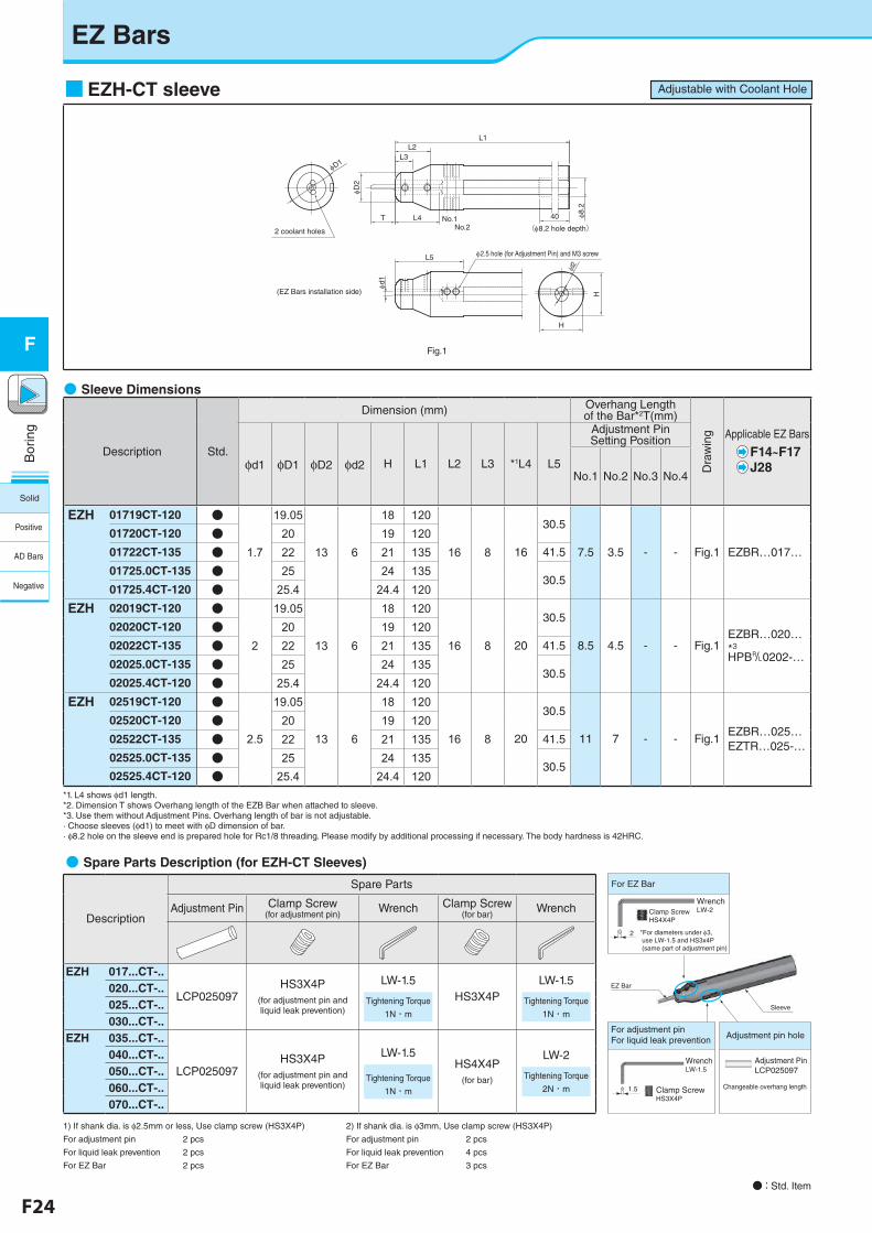
■EZH-CT sleeve
φ8.2
40
φd2
H
H
(φ8.2 hole depth)
L2L3
φD2
T
φD1
L5
L1
L4 No.1No.2
φd1
2 coolant holes
(EZ Bars installation side)
φ2.5 hole (for Adjustment Pin) and M3 screw
● : Std. Item
●�Sleeve Dimensions
Description Std.
Dimension (mm) Overhang Length of the Bar*2T(mm)
Dra
win
g Applicable EZ Bars
F14~F17J28φd1 φD1 φD2 φd2 H L1 L2 L3 *1L4 L5
Adjustment Pin Setting Position
No.1 No.2 No.3 No.4
EZH 01719CT-120 ●
1.7
19.05
13 6
18 120
16 8 16
30.5
7.5 3.5 - - Fig.1 EZBR…017…
01720CT-120 ● 20 19 12001722CT-135 ● 22 21 135 41.5
01725.0CT-135 ● 25 24 13530.5
01725.4CT-120 ● 25.4 24.4 120EZH 02019CT-120 ●
2
19.05
13 6
18 120
16 8 20
30.5
8.5 4.5 - - Fig.1EZBR…020…*3�HPB&0202-…
02020CT-120 ● 20 19 12002022CT-135 ● 22 21 135 41.5
02025.0CT-135 ● 25 24 13530.5
02025.4CT-120 ● 25.4 24.4 120EZH 02519CT-120 ●
2.5
19.05
13 6
18 120
16 8 20
30.5
11 7 - - Fig.1EZBR…025…EZTR…025-…
02520CT-120 ● 20 19 12002522CT-135 ● 22 21 135 41.5
02525.0CT-135 ● 25 24 13530.5
02525.4CT-120 ● 25.4 24.4 120*1. L4 shows φd1 length.*2. Dimension T shows Overhang length of the EZB Bar when attached to sleeve.*3. Use them without Adjustment Pins. Overhang length of bar is not adjustable.· Choose sleeves (φd1) to meet with φD dimension of bar.· φ8.2 hole on the sleeve end is prepared hole for Rc1/8 threading. Please modify by additional processing if necessary. The body hardness is 42HRC.
●�Spare Parts Description (for EZH-CT Sleeves)
Description
Spare Parts
Adjustment Pin Clamp Screw(for adjustment pin)
Wrench Clamp Screw(for bar)
Wrench
EZH 017...CT-..
LCP025097HS3X4P
(for adjustment pin and liquid leak prevention)
LW-1.5
Tightening Torque
1N・m
HS3X4PLW-1.5
Tightening Torque
1N・m
020...CT-..025...CT-..030...CT-..
EZH 035...CT-..
LCP025097HS3X4P
(for adjustment pin and liquid leak prevention)
LW-1.5
Tightening Torque
1N・m
HS4X4P(for bar)
LW-2
Tightening Torque
2N・m
040...CT-..050...CT-..060...CT-..070...CT-..
1) If shank dia. is φ2.5mm or less, Use clamp screw (HS3X4P)
For adjustment pin 2 pcs
For liquid leak prevention 2 pcs
For EZ Bar 2 pcs
2) If shank dia. is φ3mm, Use clamp screw (HS3X4P)
For adjustment pin 2 pcs
For liquid leak prevention 4 pcs
For EZ Bar 3 pcs
Sleeve
EZ Bar
For EZ Bar
Clamp ScrewHS4X4P
WrenchLW-2
*For diameters under φ3, use LW-1.5 and HS3x4P (same part of adjustment pin)
2
Clamp ScrewHS3X4P
1.5
WrenchLW-1.5
Adjustment PinLCP025097
Changeable overhang length
Adjustment pin holeFor adjustment pinFor liquid leak prevention
Fig.1
Adjustable with Coolant Hole
Solid
Positive
AD Bars
Negative
F24 F25
Bor
ing
F
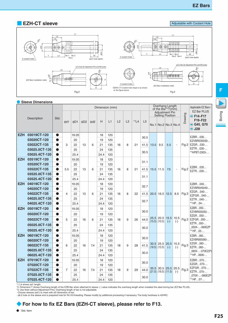
■EZH-CT sleeve
φd2
φ8.2
40
H
H
φD2
L2L3
L1
T
L5
L4
φd1
No.1 No.3No.2 No.440
φ8.2
H
H
φd2
φD2
T
L2L3
L1
L5
L4 No.1 No.3No.2
φd1
2 coolant holes2 coolant holes
2 coolant holes
EZH07..CT coolant hole shape is as shown on the �gure above.
(EZ Bars installation side)
(EZ Bars installation side)
φ2.5 hole (for Adjustment Pin) and M3 screwφ2.5 hole (for Adjustment Pin) and M3 screw
φD1
φD1
(φ8.2 hole depth)(φ8.2 hole depth)
●�Sleeve Dimensions
Description Std.
Dimension (mm) Overhang Length of the Bar*2T(mm)
Dra
win
g
Applicable EZ Bars /EZ Bar PLUS
F14~F17F19~F22G45,�G70J28
φd1 φD1 φD2 φd2 H L1 L2 L3 *1L4 L5
Adjustment Pin Setting Position
No.1 No.2 No.3 No.4
EZH 03019CT-120 ●
3
19.05
13 6
18 120
16 8 21
30.5
13.5 9.5 5.5 - Fig.2
EZBR…030…EZVBR035030-…EZGR…030-…EZTR…030-…*3HPB&0303-…
03020CT-120 ● 20 19 120
03022CT-135 ● 22 21 135 41.5
03025.0CT-135 ● 25 24 13530.5
03025.4CT-120 ● 25.4 24.4 120
EZH 03519CT-120 ●
3.5
19.05
13 6
18 120
16 8 21
31.1
15.5 11.5 7.5 - Fig.2EZBR…035…EZTR…035-…
03520CT-120 ● 20 19 120
03522CT-135 ● 22 21 135 41.5
03525.0CT-135 ● 25 24 13531.1
03525.4CT-120 ● 25.4 24.4 120
EZH 04019CT-120 ●
4
19.05
13 6
18 120
16 8 22
32.7
20.5 16.5 12.5 8.5 Fig.3
EZBR…040…EZVBR045040-…EZGR…040-…EZFGR…040-…EZTR…040-…*3 HP…04-…
04020CT-120 ● 20 19 120
04022CT-135 ● 22 21 135 41.5
04025.0CT-135 ● 25 24 13532.7
04025.4CT-120 ● 25.4 24.4 120
EZH 05019CT-120 ●
5
19.05
16 6
18 120
18 9 26
30.0
25.5(15.5)
20.5(10.5)
15.5(-)
10.5(-)
Fig.3
EZBR…050…EZVBR055050-…EZGR…050-…EZFGR…050-…EZTR…050-…_050X-…-060EZP*3�HP…05-…
05020CT-120 ● 20 19 120
05022CT-135 ● 22 21 135 44.0
05025.0CT-135 ● 25 24 13530.0
05025.4CT-120 ● 25.4 24.4 120
EZH 06019CT-120 ●
6
19.05
16 7.4
18 120
18 9 28
30.0
30.5(18.5)
25.5(13.5)
20.5(-)
15.5(-)
Fig.3
EZBR…060…EZVBR065060-…EZGR…060-…EZTR…060-…_060X-…-070EZ(P)*3 HP…0606-…
06020CT-120 ● 20 19 120
06022CT-135 ● 22 21 135 41.5
06025.0CT-135 ● 25 24 13530.0
06025.4CT-120 ● 25.4 24.4 120
EZH 07019CT-120 ●
7
19.05
16 7.4
18 120
18 9 29
30.0
35.5(21.5)
30.5(16.5)
25.5(11.5)
20.5(-)
Fig.3
EZBR…070…EZGR…070-…EZFGR…070-…EZTR…070-…_070X-…-080EZP*3 HP…07-…
07020CT-120 ● 20 19 120
07022CT-135 ● 22 21 135 44.0
07025.0CT-135 ● 25 24 13530.0
07025.4CT-120 ● 25.4 24.4 120
*1. L4 shows φd1 length.*2. Dimension T shows Overhang length of the EZB Bar when attached to sleeve. ( ) value indicates the overhang length when installed the steel boring bar (EZ Bar PLUS).*3. Use them without Adjustment Pins. Overhang length of bar is not adjustable.· Choose sleeves (φd1) to meet with φD dimension of bar.· φ8.2 hole on the sleeve end is prepared hole for Rc1/8 threading. Please modify by additional processing if necessary. The body hardness is 42HRC.
● : Std. Item
EZ Bar
◆ For how to fix EZ Bars (EZH-CT sleeve), please refer to F13.
Fig.2 Fig.3
EZ Bars
Adjustable with Coolant Hole
F26 F27
Bor
ing
F
EZ Bars
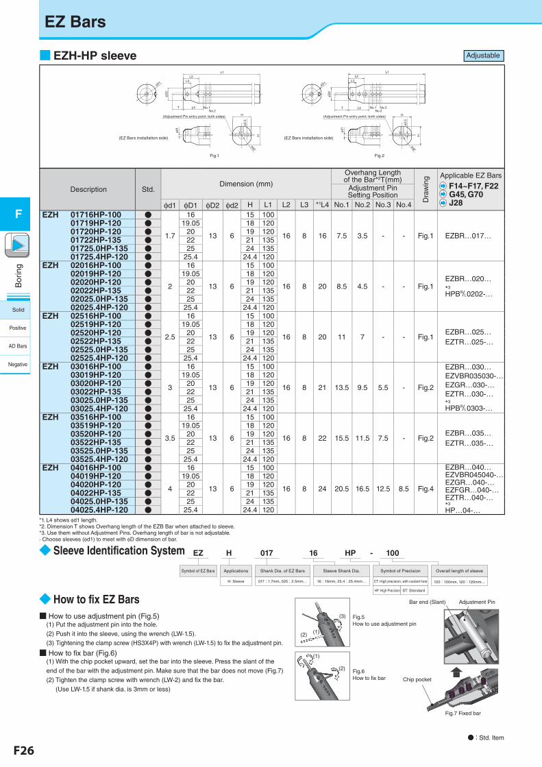
■ EZH-HP sleeve
H
φd2
H
φ2.5
φd1
φD1
L2L3
L1
φD2
L4T No.1No.2
φ2.5
H
φd2
H
φd1
No.1 No.3No.2
φD1
φD2
L2L3
L1
L4T
(Adjustment Pin entry point: both sides) (Adjustment Pin entry point: both sides)
Fig.1
(EZ Bars installation side)
Fig.2
(EZ Bars installation side)
● : Std. Item
Description Std.Dimension (mm)
Overhang Length of the Bar*2T(mm)
Dra
win
g Applicable EZ Bars
F14~F17, F22G45, G70J28
Adjustment Pin Setting Position
φd1 φD1 φD2 φd2 H L1 L2 L3 *1L4 No.1 No.2 No.3 No.4 EZH 01716HP-100 ●
1.7
16
13 6
15 100
16 8 16 7.5 3.5 - - Fig.1 EZBR…017…
01719HP-120 ● 19.05 18 12001720HP-120 ● 20 19 12001722HP-135 ● 22 21 13501725.0HP-135 ● 25 24 13501725.4HP-120 ● 25.4 24.4 120
EZH 02016HP-100 ●
2
16
13 6
15 100
16 8 20 8.5 4.5 - - Fig.1EZBR…020…*3�
HPB&0202-…
02019HP-120 ● 19.05 18 12002020HP-120 ● 20 19 12002022HP-135 ● 22 21 13502025.0HP-135 ● 25 24 13502025.4HP-120 ● 25.4 24.4 120
EZH 02516HP-100 ●
2.5
16
13 6
15 100
16 8 20 11 7 - - Fig.1EZBR…025…EZTR…025-…
02519HP-120 ● 19.05 18 12002520HP-120 ● 20 19 12002522HP-135 ● 22 21 13502525.0HP-135 ● 25 24 13502525.4HP-120 ● 25.4 24.4 120
EZH 03016HP-100 ●
3
16
13 6
15 100
16 8 21 13.5 9.5 5.5 - Fig.2
EZBR…030…EZVBR035030-…EZGR…030-…EZTR…030-…*3�
HPB&0303-…
03019HP-120 ● 19.05 18 12003020HP-120 ● 20 19 12003022HP-135 ● 22 21 13503025.0HP-135 ● 25 24 13503025.4HP-120 ● 25.4 24.4 120
EZH 03516HP-100 ●
3.5
16
13 6
15 100
16 8 22 15.5 11.5 7.5 - Fig.2EZBR…035…EZTR…035-…
03519HP-120 ● 19.05 18 12003520HP-120 ● 20 19 12003522HP-135 ● 22 21 13503525.0HP-135 ● 25 24 13503525.4HP-120 ● 25.4 24.4 120
EZH 04016HP-100 ●
4
16
13 6
15 100
16 8 24 20.5 16.5 12.5 8.5 Fig.4
EZBR…040…EZVBR045040-…EZGR…040-…EZFGR…040-…EZTR…040-…*3
HP…04-…
04019HP-120 ● 19.05 18 12004020HP-120 ● 20 19 12004022HP-135 ● 22 21 13504025.0HP-135 ● 25 24 13504025.4HP-120 ● 25.4 24.4 120
*1. L4 shows φd1 length.*2. Dimension T shows Overhang length of the EZB Bar when attached to sleeve.*3. Use them without Adjustment Pins. Overhang length of bar is not adjustable.· Choose sleeves (φd1) to meet with φD dimension of bar.
◆ Sleeve Identification System
◆ How to fix EZ Bars■ How to use adjustment pin (Fig.5)
(1) Put the adjustment pin into the hole.(2) Push it into the sleeve, using the wrench (LW-1.5).(3) Tightening the clamp screw (HS3X4P) with wrench (LW-1.5) to fix the adjustment pin.
■ How to fix bar (Fig.6)(1) With the chip pocket upward, set the bar into the sleeve. Press the slant of the end of the bar with the adjustment pin. Make sure that the bar does not move (Fig.7)(2) Tighten the clamp screw with wrench (LW-2) and fix the bar.
(Use LW-1.5 if shank dia. is 3mm or less)
017
Shank Dia. of EZ Bars
017:1.7mm, 025:2.5mm…
Sleeve Shank Dia.
16:16mm, 25.4:25.4mm…
16
CT: High precision, with coolant hole
HP: High Precision ST: Standard
Symbol of Precision
HP -
Overall length of sleeve
100:100mm, 120:120mm…
100EZ
Symbol of EZ Bars
H
Applications
H: Sleeve
Adjustable
位置決めピンチップ後端傾斜面
図5位置決めピン装着方法
図 6チップ装着方法
図7 チップ固定状態
チップポケット
(3)
(1)
(1)
(2)
(2)
Adjustment PinBar end (Slant)
Fig.5How to use adjustment pin
Fig.6How to fix bar
Fig.7 Fixed bar
Chip pocket
Solid
Positive
AD Bars
Negative
F26 F27
Bor
ing
F
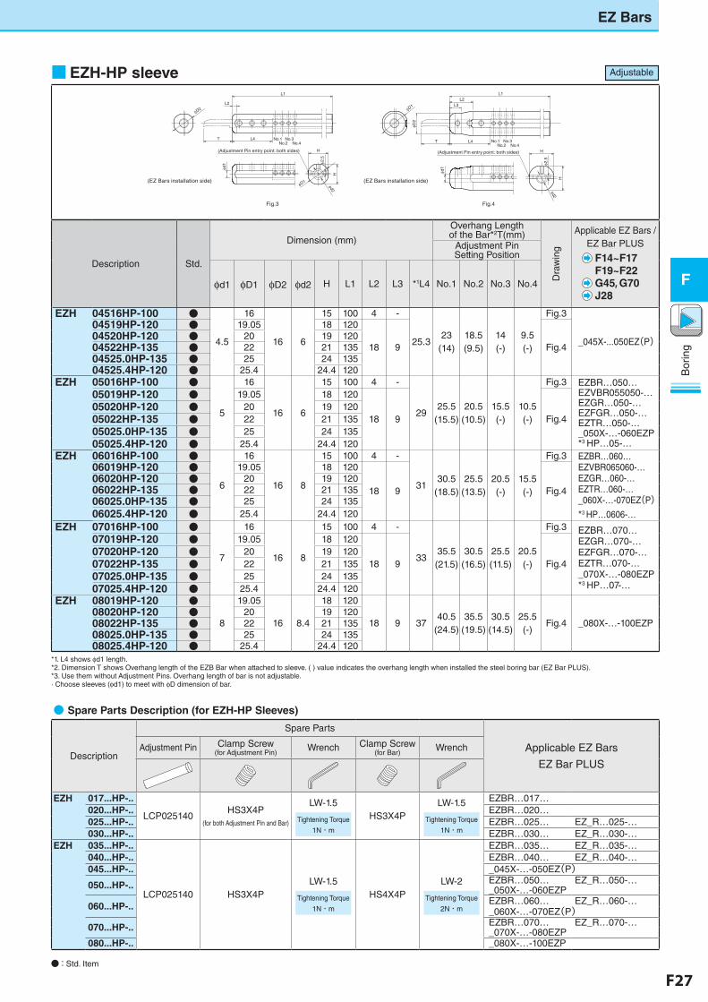
●�Spare Parts Description (for EZH-HP Sleeves)
Description
Spare Parts
Applicable EZ Bars
EZ Bar PLUS
Adjustment Pin Clamp Screw(for Adjustment Pin)
Wrench Clamp Screw(for Bar)
Wrench
EZH 017...HP-..
LCP025140HS3X4P
(for both Adjustment Pin and Bar)
LW-1.5
Tightening Torque
1N・m
HS3X4PLW-1.5
Tightening Torque
1N・m
EZBR…017…020...HP-.. EZBR…020…025...HP-.. EZBR…025… EZ_R…025-…030...HP-.. EZBR…030… EZ_R…030-…
EZH 035...HP-..
LCP025140 HS3X4PLW-1.5
Tightening Torque
1N・m
HS4X4PLW-2
Tightening Torque
2N・m
EZBR…035… EZ_R…035-…040...HP-.. EZBR…040… EZ_R…040-…045...HP-.. _045X-…-050EZ(P)050...HP-.. EZBR…050… EZ_R…050-…
_050X-…-060EZP
060...HP-.. EZBR…060… EZ_R…060-…_060X-…-070EZ(P)
070...HP-.. EZBR…070… EZ_R…070-…_070X-…-080EZP
080...HP-.. _080X-…-100EZP
■EZH-HP sleeve
φd1
L1
L2
φD2
No.1 No.3No.2 No.4
L4T
φ2.5
φd2
H
H
No.1 No.3No.2 No.4
φD1
φD2
L2L3
L1
L4T
φ2.5
Hφd2
H
φd1
(Adjustment Pin entry point: both sides) (Adjustment Pin entry point: both sides)
φD1
Fig.3
(EZ Bars installation side)
Fig.4
(EZ Bars installation side)
● : Std. Item
EZ Bars
Description Std.
Dimension (mm)
Overhang Length of the Bar*2T(mm)
Dra
win
g
Applicable EZ Bars / EZ Bar PLUS
F14~F17F19~F22G45, G70J28
Adjustment Pin Setting Position
φd1 φD1 φD2 φd2 H L1 L2 L3 *1L4 No.1 No.2 No.3 No.4
EZH 04516HP-100 ●
4.5
16
16 6
15 100 4 -
25.323
(14)18.5 (9.5)
14 (-)
9.5 (-)
Fig.3
_045X-...050EZ(P)
04519HP-120 ● 19.05 18 120
18 9 Fig.404520HP-120 ● 20 19 12004522HP-135 ● 22 21 13504525.0HP-135 ● 25 24 13504525.4HP-120 ● 25.4 24.4 120
EZH 05016HP-100 ●
5
16
16 6
15 100 4 -
2925.5
(15.5)20.5
(10.5)15.5 (-)
10.5 (-)
Fig.3 EZBR…050…EZVBR055050-…EZGR…050-…EZFGR…050-…EZTR…050-…_050X-…-060EZP*3�HP…05-…
05019HP-120 ● 19.05 18 120
18 9 Fig.405020HP-120 ● 20 19 12005022HP-135 ● 22 21 13505025.0HP-135 ● 25 24 13505025.4HP-120 ● 25.4 24.4 120
EZH 06016HP-100 ●
6
16
16 8
15 100 4 -
3130.5
(18.5)25.5
(13.5)20.5(-)
15.5(-)
Fig.3 EZBR…060…EZVBR065060-…EZGR…060-…EZTR…060-…_060X-…-070EZ(P)*3�HP…0606-…
06019HP-120 ● 19.05 18 120
18 9 Fig.406020HP-120 ● 20 19 12006022HP-135 ● 22 21 13506025.0HP-135 ● 25 24 13506025.4HP-120 ● 25.4 24.4 120
EZH 07016HP-100 ●
7
16
16 8
15 100 4 -
3335.5 (21.5)
30.5 (16.5)
25.5 (11.5)
20.5(-)
Fig.3 EZBR…070…EZGR…070-…EZFGR…070-…EZTR…070-…_070X-…-080EZP*3�HP…07-…
07019HP-120 ● 19.05 18 120
18 9 Fig.407020HP-120 ● 20 19 12007022HP-135 ● 22 21 13507025.0HP-135 ● 25 24 13507025.4HP-120 ● 25.4 24.4 120
EZH 08019HP-120 ●
8
19.05
16 8.4
18 120
18 9 3740.5
(24.5)35.5
(19.5)30.5
(14.5)25.5(-)
Fig.4 _080X-…-100EZP08020HP-120 ● 20 19 12008022HP-135 ● 22 21 13508025.0HP-135 ● 25 24 13508025.4HP-120 ● 25.4 24.4 120
*1. L4 shows φd1 length.*2. Dimension T shows Overhang length of the EZB Bar when attached to sleeve. ( ) value indicates the overhang length when installed the steel boring bar (EZ Bar PLUS).*3. Use them without Adjustment Pins. Overhang length of bar is not adjustable.· Choose sleeves (φd1) to meet with φD dimension of bar.
Adjustable
F28 F29
Bor
ing
F
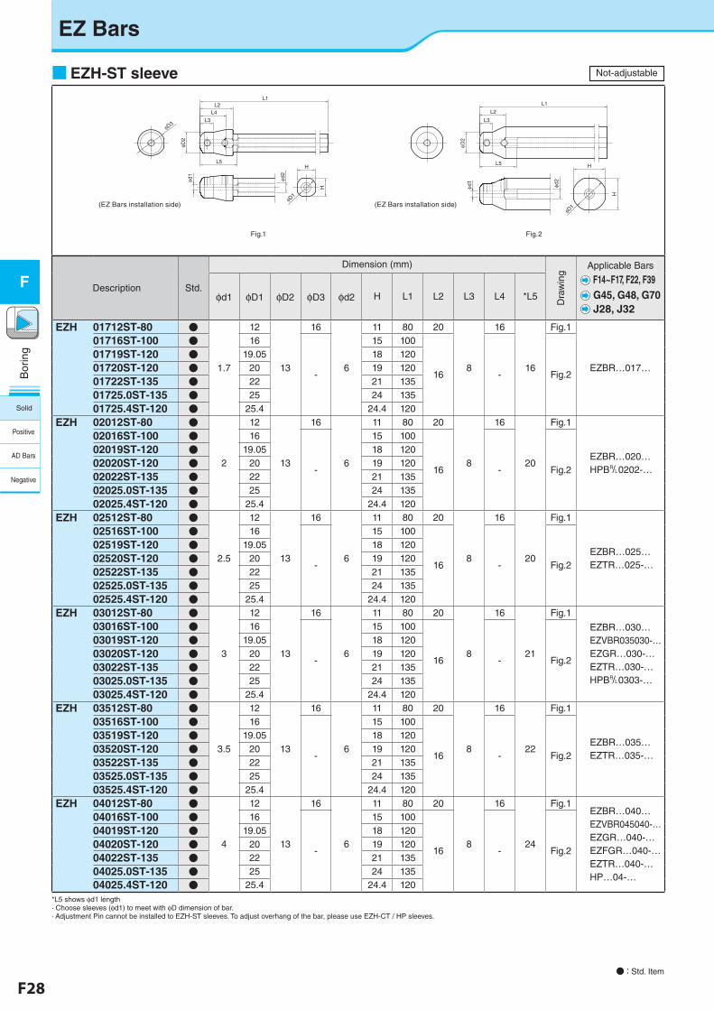
EZ Bars
■EZH-ST sleeveL1
L3
L2
φD3
φD2
L4
φd2
φD1
L5H
H
φd1
H
φD2
L5
φd2
φD1
H
L3
L2
L1
φd1
Fig.1
(EZ Bars installation side)
Fig.2
(EZ Bars installation side)
● : Std. Item
Description Std.
Dimension (mm)
Dra
win
g
Applicable Bars
G45, G48, G70J28, J32
φd1 φD1 φD2 φD3 φd2 H L1 L2 L3 L4 *L5
EZH 01712ST-80 ●
1.7
12
13
16
6
11 80 20
8
16
16
Fig.1
EZBR…017…
01716ST-100 ● 16
-
15 100
16 - Fig.2
01719ST-120 ● 19.05 18 120
01720ST-120 ● 20 19 120
01722ST-135 ● 22 21 135
01725.0ST-135 ● 25 24 135
01725.4ST-120 ● 25.4 24.4 120
EZH 02012ST-80 ●
2
12
13
16
6
11 80 20
8
16
20
Fig.1
EZBR…020…HPB&0202-…
02016ST-100 ● 16
-
15 100
16 - Fig.2
02019ST-120 ● 19.05 18 120
02020ST-120 ● 20 19 120
02022ST-135 ● 22 21 135
02025.0ST-135 ● 25 24 135
02025.4ST-120 ● 25.4 24.4 120
EZH 02512ST-80 ●
2.5
12
13
16
6
11 80 20
8
16
20
Fig.1
EZBR…025…EZTR…025-…
02516ST-100 ● 16
-
15 100
16 - Fig.2
02519ST-120 ● 19.05 18 120
02520ST-120 ● 20 19 120
02522ST-135 ● 22 21 135
02525.0ST-135 ● 25 24 135
02525.4ST-120 ● 25.4 24.4 120
EZH 03012ST-80 ●
3
12
13
16
6
11 80 20
8
16
21
Fig.1
EZBR…030…EZVBR035030-…EZGR…030-…EZTR…030-…HPB&0303-…
03016ST-100 ● 16
-
15 100
16 - Fig.2
03019ST-120 ● 19.05 18 120
03020ST-120 ● 20 19 120
03022ST-135 ● 22 21 135
03025.0ST-135 ● 25 24 135
03025.4ST-120 ● 25.4 24.4 120
EZH 03512ST-80 ●
3.5
12
13
16
6
11 80 20
8
16
22
Fig.1
EZBR…035…EZTR…035-…
03516ST-100 ● 16
-
15 100
16 - Fig.2
03519ST-120 ● 19.05 18 120
03520ST-120 ● 20 19 120
03522ST-135 ● 22 21 135
03525.0ST-135 ● 25 24 135
03525.4ST-120 ● 25.4 24.4 120
EZH 04012ST-80 ●
4
12
13
16
6
11 80 20
8
16
24
Fig.1EZBR…040…EZVBR045040-…EZGR…040-…EZFGR…040-…EZTR…040-…HP…04-…
04016ST-100 ● 16
-
15 100
16 - Fig.2
04019ST-120 ● 19.05 18 120
04020ST-120 ● 20 19 120
04022ST-135 ● 22 21 135
04025.0ST-135 ● 25 24 13504025.4ST-120 ● 25.4 24.4 120
*L5 shows φd1 length· Choose sleeves (φd1) to meet with φD dimension of bar.· Adjustment Pin cannot be installed to EZH-ST sleeves. To adjust overhang of the bar, please use EZH-CT / HP sleeves.
F14~F17, F22, F39
Not-adjustable
Solid
Positive
AD Bars
Negative
F28 F29
Bor
ing
F
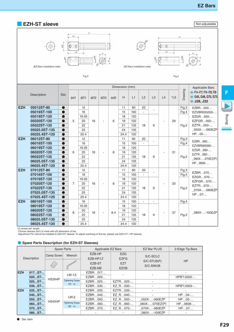
■EZH-ST sleeve
L1
L2
H
H
φD2
L5
φd2
φD1
φd1
L1
φD2
H
H
L5
φd2
φD1
φd1
Fig.3
(EZ Bars installation side)
Fig.4
(EZ Bars installation side)
● : Std. Item
EZ Bars
Description Std.
Dimension (mm)
Dra
win
g
Applicable Bars
G45, G48, G70, G73J28, J32
φd1 φD1 φD2 φD3 φd2 H L1 L2 L3 L4 *L5
EZH 05012ST-80 ●
5
12
16 - 6
11 80 20-
- 29
Fig.3 EZBR…050…EZVBR055050-…EZGR…050-…EZFGR…050-…EZTR…050-…_050X-…-060EZPHP…05-…
05016ST-100 ● 16 15 100 - Fig.4
05019ST-120 ● 19.05 18 120
18 9 Fig.205020ST-120 ● 20 19 120
05022ST-135 ● 22 21 135
05025.0ST-135 ● 25 24 135
05025.4ST-120 ● 25.4 24.4 120
EZH 06012ST-80 ●
6
12
16 - 8
11 80 20-
- 31
Fig.3EZBR…060…EZVBR065060-…EZGR…060-…EZTR…060-…_060X-…-070EZ(P)HP…0606-…
06016ST-100 ● 16 15 100 - Fig.4
06019ST-120 ● 19.05 18 120
18 9 Fig.206020ST-120 ● 20 19 120
06022ST-135 ● 22 21 135
06025.0ST-135 ● 25 24 135
06025.4ST-120 ● 25.4 24.4 120
EZH 07012ST-80 ●
7
12
16 - 8
11 80 20-
- 33
Fig.3EZBR…070…EZGR…070-…EZFGR…070-…EZTR…070-…_070X-…-080EZPHP…07-…
07016ST-100 ● 16 15 100 - Fig.4
07019ST-120 ● 19.05 18 120
18 9 Fig.207020ST-120 ● 20 19 120
07022ST-135 ● 22 21 135
07025.0ST-135 ● 25 24 135
07025.4ST-120 ● 25.4 24.4 120
EZH 08016ST-100 ●
8
16
16 - 8.4
15 100 - -
- 37
Fig.4
_080X-…-100EZP
08019ST-120 ● 19.05 18 120
18 9 Fig.208020ST-120 ● 20 19 120
08022ST-135 ● 22 21 135
08025.0ST-135 ● 25 24 13508025.4ST-120 ● 25.4 24.4 120
*L5 shows φd1 length· Choose sleeves (φd1) to meet with φD dimension of bar.· Adjustment Pin cannot be installed to EZH-ST sleeves. To adjust overhang of the bar, please use EZH-CT / HP sleeves.
F14~F17, F19~F22, F39
●�Spare Parts Description (for EZH-ST Sleeves)�
Description
Spare Parts Applicable EZ Bars EZ Bar PLUS 2-Edge Tip-Bars
Clamp Screw Wrench EZB-HP
EZB-HP-LT
EZB-ST
EZB-NB
EZG
EZFG
EZT
EZVB
S/C-SCLC
S/C-STLB(P)
S/C-SWUB
HP
EZH 017...ST-..
HS3X4PLW-1.5
Tightening Torque
1N・m
EZBR…017…- -
-020...ST-.. EZBR…020… HPB&0202-…025...ST-.. EZBR…025… EZTR…025-… - -030...ST-.. EZBR…030… EZ_R…030-… - HPB&0303-…
EZH 035...ST-..
HS4X4PLW-2
Tightening Torque
2N・m
EZBR…035… EZTR…035-… - -040...ST-.. EZBR…040… EZ_R…040-… - HP…04-…050...ST-.. EZBR…050… EZ_R…050-… _050X-…-060EZP HP…05-…060...ST-.. EZBR…060… EZ_R…060-… _060X-…-070EZ(P) HP…0606-…070...ST-.. EZBR…070… EZ_R…070-… _070X-…-080EZP HP…07-…080...ST-.. - - _080X-…-100EZP -
Not-adjustable
F30 F31
Bor
ing
F
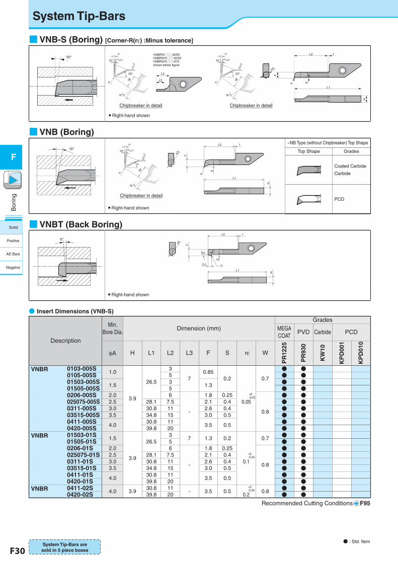
System Tip-Bars
● : Std. Item
●�Insert Dimensions (VNB-S)
Description
Min. Bore Dia.
Dimension (mm)Grades
MEGACOAT
PVD Carbide PCD
φA H L1 L2 L3 F S rε W
PR
1225
PR
930
KW
10
KP
D00
1
KP
D01
0
VNBR 0103-005S1.0
3.9
26.5
3
70.85
0.2
+0-0.02
0.05
0.7
● ●0105-005S 5 ● ●01503-005S
1.53
1.3 ● ●01505-005S 5 ● ●0206-005S 2.0 6
-
1.8 0.25
0.8
● ●025075-005S 2.5 28.1 7.5 2.1 0.4 ● ●0311-005S 3.0 30.8 11 2.6 0.4 ● ●03515-005S 3.5 34.8 15 3.0 0.5 ● ●0411-005S
4.030.8 11
3.5 0.5 ● ●0420-005S 39.8 20 ● ●
VNBR 01503-01S1.5
3.9
26.53
7 1.3 0.2
+0-0.03
0.1
0.7 ● ●01505-01S 5 ● ●0206-01S 2.0 6
-
1.8 0.25
0.8
● ●025075-01S 2.5 28.1 7.5 2.1 0.4 ● ●0311-01S 3.0 30.8 11 2.6 0.4 ● ●03515-01S 3.5 34.8 15 3.0 0.5 ● ●0411-01S
4.030.8 11
3.5 0.5 ● ●0420-01S 39.8 20 ● ●
VNBR 0411-02S 4.0 3.930.8 11
- 3.5 0.5+0-0.04
0.20.8 ● ●
0420-02S 39.8 20 ● ●Recommended Cutting Conditions F95
System Tip-Bars are sold in 5 piece boxes
Chipbreaker in detail
Chipbreaker in detail
Chipbreaker in detail
■VNB-S (Boring) [Corner-R(rε) :Minus tolerance]
10°L2
S
F
r
1
L1
H
A
L2
L3
shows below figure
VNBR01○○-005SVNBR015○○-005SVNBR015○○-01S
30°
15°
10°
7°
r
W
30°
18°
10°
7°
r
W
● Right-hand shown
■VNBT (Back Boring)
5°
H
15°
2.0
S
r
5°
F
1L2
L1
A
● Right-hand shown
■VNB (Boring)
10°
r
F
H
S
1
18°
10°
7°
r
W
L2
L1A
● Right-hand shown
−NB Type (without Chipbreaker) Top Shape
Top Shape Grades
Coated Carbide�Carbide
PCD
Solid
Positive
AD Bars
Negative
F30 F31
Bor
ing
F
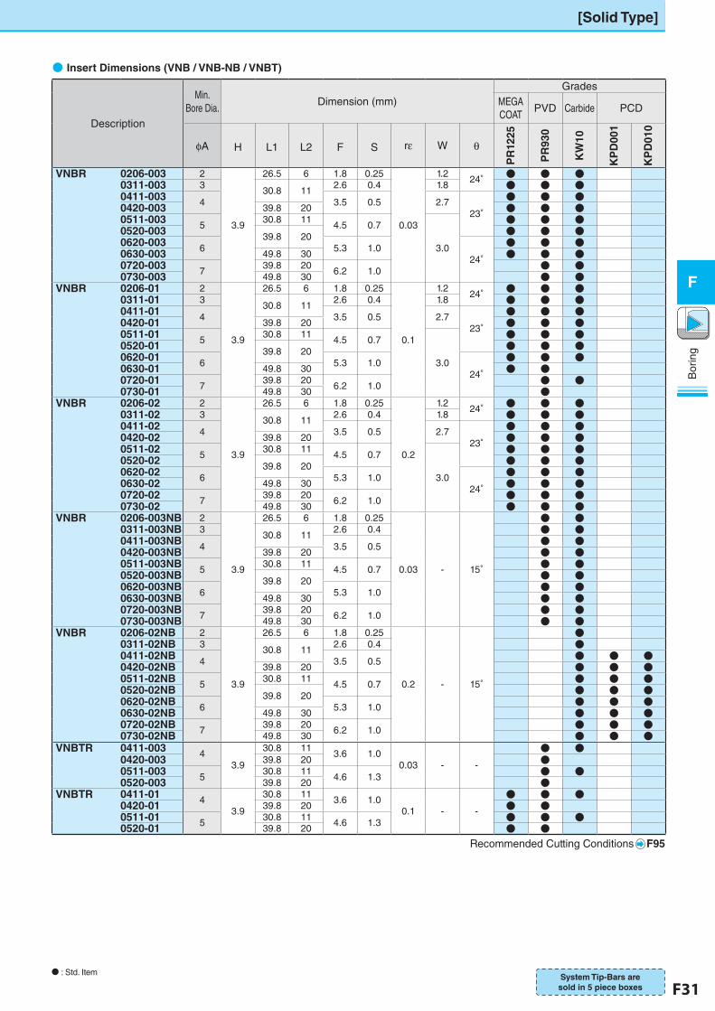
[Solid Type]
N : Std. Item
●�Insert Dimensions (VNB / VNB-NB / VNBT)
Description
Min. Bore Dia.
Dimension (mm)Grades
MEGACOAT
PVD Carbide PCD
φA H L1 L2 F S rε W θ
PR
1225
PR
930
KW
10
KP
D00
1
KP
D01
0
VNBR 0206-003 2
3.9
26.5 6 1.8 0.25
0.03
1.224° ● ● ●
0311-003 330.8 11
2.6 0.4 1.8 ● ● ●0411-003 4 3.5 0.5 2.7
23°● ● ●
0420-003 39.8 20 ● ● ●0511-003 5
30.8 114.5 0.7
3.0
● ● ●0520-003 39.8 20 ● ● ●0620-003 6 5.3 1.0
24°● ● ●
0630-003 49.8 30 ● ● ●0720-003 7
39.8 206.2 1.0 ● ●
0730-003 49.8 30 ● ●VNBR 0206-01 2
3.9
26.5 6 1.8 0.25
0.1
1.224° ● ● ●
0311-01 330.8 11
2.6 0.4 1.8 ● ● ●0411-01 4 3.5 0.5 2.7
23°● ● ●
0420-01 39.8 20 ● ● ●0511-01 5
30.8 114.5 0.7
3.0
● ● ●0520-01 39.8 20 ● ● ●0620-01 6 5.3 1.0
24°● ● ●
0630-01 49.8 30 ● ●0720-01 7
39.8 206.2 1.0 ● ●
0730-01 49.8 30 ●VNBR 0206-02 2
3.9
26.5 6 1.8 0.25
0.2
1.224° ● ● ●
0311-02 330.8 11
2.6 0.4 1.8 ● ● ●0411-02 4 3.5 0.5 2.7
23°● ● ●
0420-02 39.8 20 ● ● ●0511-02 5
30.8 114.5 0.7
3.0
● ● ●0520-02 39.8 20 ● ● ●0620-02 6 5.3 1.0
24°● ● ●
0630-02 49.8 30 ● ● ●0720-02 7
39.8 206.2 1.0 ● ● ●
0730-02 49.8 30 ● ● ●VNBR 0206-003NB 2
3.9
26.5 6 1.8 0.25
0.03 - 15°
● ●0311-003NB 3
30.8 112.6 0.4 ● ●
0411-003NB 4 3.5 0.5 ● ●0420-003NB 39.8 20 ● ●0511-003NB 5
30.8 114.5 0.7 ● ●
0520-003NB 39.8 20 ● ●0620-003NB 6 5.3 1.0 ● ●0630-003NB 49.8 30 ● ●0720-003NB 7
39.8 206.2 1.0 ● ●
0730-003NB 49.8 30 ● ●VNBR 0206-02NB 2
3.9
26.5 6 1.8 0.25
0.2 - 15°
●0311-02NB 3
30.8 112.6 0.4 ●
0411-02NB 4 3.5 0.5 ● ● ●0420-02NB 39.8 20 ● ● ●0511-02NB 5
30.8 114.5 0.7 ● ● ●
0520-02NB 39.8 20 ● ● ●0620-02NB 6 5.3 1.0 ● ● ●0630-02NB 49.8 30 ● ● ●0720-02NB 7
39.8 206.2 1.0 ● ● ●
0730-02NB 49.8 30 ● ● ●VNBTR 0411-003 4
3.9
30.8 113.6 1.0
0.03 - -
● ●0420-003 39.8 20 ●0511-003 5
30.8 114.6 1.3 ● ●
0520-003 39.8 20 ●VNBTR 0411-01 4
3.9
30.8 113.6 1.0
0.1 - -
● ● ●0420-01 39.8 20 ● ●0511-01 5 30.8 11 4.6 1.3 ● ● ●0520-01 39.8 20 ● ●
Recommended Cutting Conditions F95
System Tip-Bars are sold in 5 piece boxes
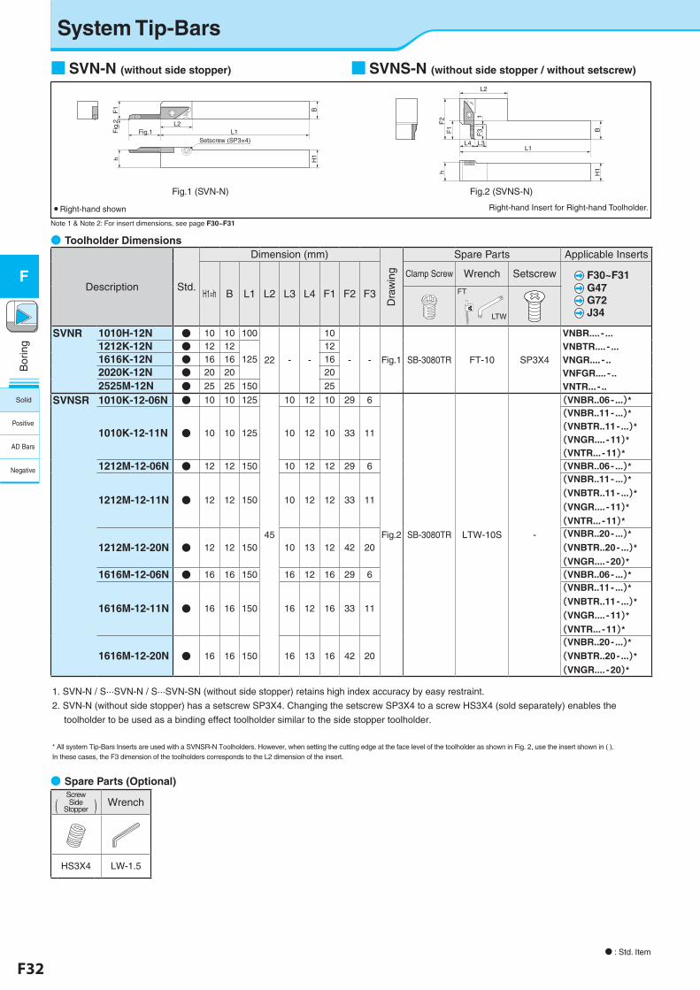
F32 F33
Bor
ing
F
●�Spare Parts (Optional)
(ScrewSide
Stopper ) Wrench
HS3X4 LW-1.5
System Tip-Bars
N : Std. Item
■SVN-N (without side stopper) ■SVNS-N (without side stopper / without setscrew)
L2
1F
3
L1
F1
L4 L3
F2
h
BH
1
Note 1 & Note 2: For insert dimensions, see page F30~F31
H1h
L2L1
B
Fig.1Setscrew (SP3×4)
Fig
.2F
1
Fig.1 (SVN-N) Fig.2 (SVNS-N)
● Right-hand shown Right-hand Insert for Right-hand Toolholder.
●�Toolholder Dimensions
Description Std.
Dimension (mm)
Dra
win
g
Spare Parts Applicable Inserts
H1=h B L1 L2 L3 L4 F1 F2 F3
Clamp Screw Wrench Setscrew F30~F31 G47 G72 J34
FT��� �
LTW
SVNR 1010H-12N ● 10 10 100
22 - -
10
- - Fig.1 SB-3080TR FT-10 SP3X4
VNBR.... - ...VNBTR.... - ...VNGR.... - ..VNFGR.... - ..VNTR... - ..
1212K-12N ● 12 12125
121616K-12N ● 16 16 162020K-12N ● 20 20 20
2525M-12N ● 25 25 150 25
SVNSR 1010K-12-06N ● 10 10 125
45
10 12 10 29 6
Fig.2 SB-3080TR LTW-10S -
(VNBR..06- ...)*
1010K-12-11N ● 10 10 125 10 12 10 33 11
(VNBR..11- ...)*(VNBTR..11- ...)*(VNGR.... -11)*(VNTR... -11)*
1212M-12-06N ● 12 12 150 10 12 12 29 6 (VNBR..06- ...)*
1212M-12-11N ● 12 12 150 10 12 12 33 11
(VNBR..11- ...)*(VNBTR..11- ...)*(VNGR.... -11)*(VNTR... -11)*
1212M-12-20N ● 12 12 150 10 13 12 42 20(VNBR..20- ...)*(VNBTR..20- ...)*(VNGR.... -20)*
1616M-12-06N ● 16 16 150 16 12 16 29 6 (VNBR..06- ...)*
1616M-12-11N ● 16 16 150 16 12 16 33 11
(VNBR..11- ...)*(VNBTR..11- ...)*(VNGR.... -11)*(VNTR... -11)*
1616M-12-20N ● 16 16 150 16 13 16 42 20(VNBR..20- ...)*(VNBTR..20- ...)*(VNGR.... -20)*
1. SVN-N / S···SVN-N / S···SVN-SN (without side stopper) retains high index accuracy by easy restraint.
2. SVN-N (without side stopper) has a setscrew SP3X4. Changing the setscrew SP3X4 to a screw HS3X4 (sold separately) enables the
toolholder to be used as a binding effect toolholder similar to the side stopper toolholder.
* All system Tip-Bars Inserts are used with a SVNSR-N Toolholders. However, when setting the cutting edge at the face level of the toolholder as shown in Fig. 2, use the insert shown in ( ).In these cases, the F3 dimension of the toolholders corresponds to the L2 dimension of the insert.
Solid
Positive
AD Bars
Negative
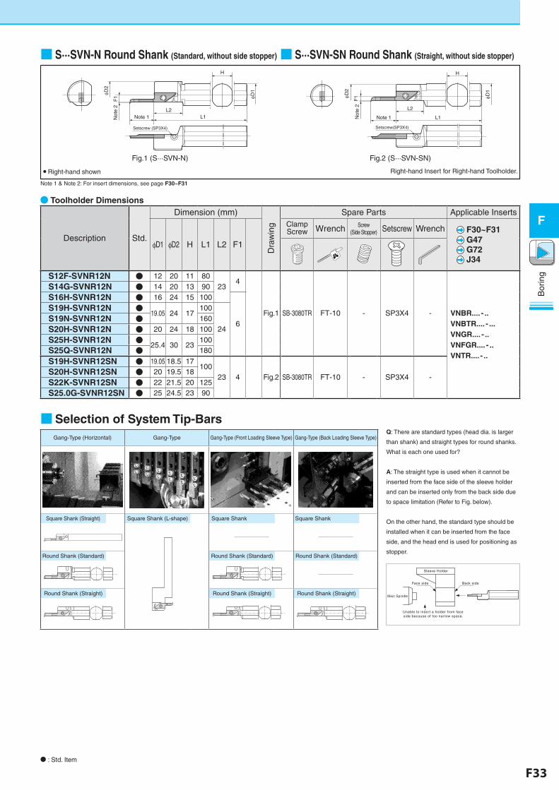
F32 F33
Bor
ing
F
■SVNS-N (without side stopper / without setscrew)
N : Std. Item
■ S···SVN-N Round Shank (Standard, without side stopper)■ S···SVN-SN Round Shank (Straight, without side stopper)
H
L2
F1
Note 1Not
e 2
L1
D1D2
Setscrew(SP3X4)
H
Note 1 L1
D1D
2L2
F1
Not
e 2
Setscrew (SP3X4)
Fig.1 (S···SVN-N) Fig.2 (S···SVN-SN)
● Right-hand shown Right-hand Insert for Right-hand Toolholder.
Note 1 & Note 2: For insert dimensions, see page F30~F31
●�Toolholder Dimensions
Description Std.
Dimension (mm)
Dra
win
g
Spare Parts Applicable Inserts
φD1 φD2 H L1 L2 F1
Clamp Screw Wrench Screw
(Side Stopper) Setscrew Wrench F30~F31 G47 G72 J34
S12F-SVNR12N ● 12 20 11 8023
4
Fig.1 SB-3080TR FT-10 - SP3X4 - VNBR.... - ..VNBTR.... - ...VNGR.... - ..VNFGR.... - ..VNTR.... - ..
S14G-SVNR12N ● 14 20 13 90
S16H-SVNR12N ● 16 24 15 100
6
S19H-SVNR12N ●19.05 24 17
100
24S19N-SVNR12N ● 160
S20H-SVNR12N ● 20 24 18 100
S25H-SVNR12N ●25.4 30 23
100S25Q-SVNR12N ● 180
S19H-SVNR12SN ● 19.05 18.5 17100
23 4 Fig.2 SB-3080TR FT-10 - SP3X4 -S20H-SVNR12SN ● 20 19.5 18
S22K-SVNR12SN ● 22 21.5 20 125S25.0G-SVNR12SN ● 25 24.5 23 90
■Selection of System Tip-Bars
Sleeve Holder
Main Spindle
Face side Back side
Unable to insert a holder from face side because of too narrow space.
Q: There are standard types (head dia. is larger
than shank) and straight types for round shanks.
What is each one used for?
A: The straight type is used when it cannot be
inserted from the face side of the sleeve holder
and can be inserted only from the back side due
to space limitation (Refer to Fig. below).
On the other hand, the standard type should be
installed when it can be inserted from the face
side, and the head end is used for positioning as
stopper.
Gang-Type (Horizontal) Gang-Type Gang-Type (Front Loading Sleeve Type) Gang-Type (Back Loading Sleeve Type)
Square Shank (Straight) Square Shank (L-shape) Square Shank□□□) Square Shank□□□□□)
Round Shank (Standard) Round Shank (Standard) Round Shank (Standard)
Round Shank (Straight) Round Shank (Straight) Round Shank (Straight)
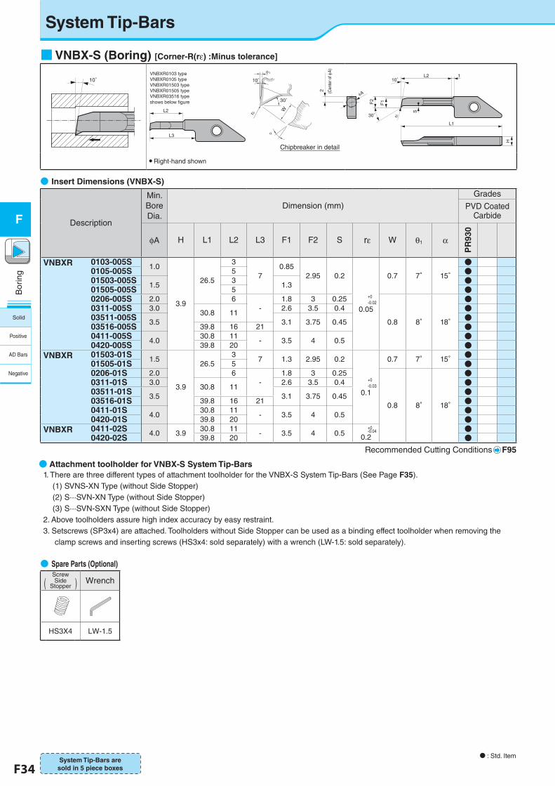
F34 F35
Bor
ing
F
System Tip-Bars
N : Std. Item
●�Insert Dimensions (VNBX-S)
● Attachment toolholder for VNBX-S System Tip-Bars 1. There are three different types of attachment toolholder for the VNBX-S System Tip-Bars (See Page F35). (1) SVNS-XN Type (without Side Stopper) (2) S···SVN-XN Type (without Side Stopper) (3) S···SVN-SXN Type (without Side Stopper) 2. Above toolholders assure high index accuracy by easy restraint. 3. Setscrews (SP3x4) are attached. Toolholders without Side Stopper can be used as a binding effect toolholder when removing the
clamp screws and inserting screws (HS3x4: sold separately) with a wrench (LW-1.5: sold separately).
Description
Min. Bore Dia.
Dimension (mm)Grades
PVD Coated Carbide
φA H L1 L2 L3 F1 F2 S rε W θ1 α
PR
930
VNBXR 0103-005S1.0
3.9
26.5
3
70.85
2.95 0.2
+0-0.02
0.05
0.7 7° 15°
●0105-005S 5 ●01503-005S
1.53
1.3 ●01505-005S 5 ●0206-005S 2.0 6
-1.8 3 0.25
0.8 8° 18°
●0311-005S 3.0
30.8 112.6 3.5 0.4 ●
03511-005S3.5 3.1 3.75 0.45 ●
03516-005S 39.8 16 21 ●0411-005S
4.030.8 11
- 3.5 4 0.5 ●0420-005S 39.8 20 ●
VNBXR 01503-01S1.5
3.9
26.53
7 1.3 2.95 0.2
+0-0.03
0.1
0.7 7° 15° ●01505-01S 5 ●0206-01S 2.0 6
-1.8 3 0.25
0.8 8° 18°
●0311-01S 3.0
30.8 112.6 3.5 0.4 ●
03511-01S3.5 3.1 3.75 0.45 ●
03516-01S 39.8 16 21 ●0411-01S
4.030.8 11
- 3.5 4 0.5 ●0420-01S 39.8 20 ●
VNBXR 0411-02S 4.0 3.930.8 11
- 3.5 4 0.5+0-0.04
0.2●
0420-02S 39.8 20 ●Recommended Cutting Conditions F95
System Tip-Bars are sold in 5 piece boxes
●�Spare Parts (Optional)
(ScrewSide
Stopper ) Wrench
HS3X4 LW-1.5
■VNBX-S (Boring) [Corner-R(rε) :Minus tolerance]
10° 10°
30° r
L2 1
F2
2 (Cen
ter o
f A)
S
F1
L1
H
L2
L3
A
shows below figure
VNBXR0103 typeVNBXR0105 typeVNBXR01503 typeVNBXR01505 typeVNBXR03516 type
30°
10°1
r
W
● Right-hand shown
Chipbreaker in detail
Solid
Positive
AD Bars
Negative
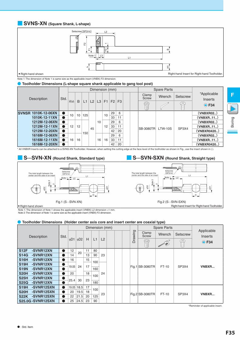
F34 F35
Bor
ing
F
■SVNS-XN (Square Shank, L-shape)
●�Toolholder Dimensions (L-shape square shank applicable to gang tool post)
■S···SVN-XN (Round Shank, Standard type) ■S···SVN-SXN (Round Shank, Straight type)
●�Toolholder Dimensions (Holder center axis core and insert center are coaxial type)
Note 1: The dimension of Note 1 is same size as the applicable insert (VNBX) F2 dimension.
L2
F1
F3
1
L3L1
Note 1
Setscrew(SP3×4)
F2
BH
1h
● Right-hand shown Right-hand Insert for Right-hand Toolholder.
N : Std. Item
Description Std.
Dimension (mm) Spare Parts*Applicable
Inserts
F34H1=h B L1 L2 L3 F1 F2 F3
Clamp Screw Wrench Setscrew
SVNSR 1010K-12-06XN ●10 10 125
45
10
1029 6
SB-3080TR LTW-10S SP3X4
(VNBXR02..)1010K-12-11XN ● 33 11 (VNBXR..11..)1212M-12-06XN ●
12 12
150
1229 6 (VNBXR02..)
1212M-12-11XN ● 33 11 (VNBXR..11..)1212M-12-20XN ● 42 20 (VNBXR0420..)1616M-12-06XN ●
16 16 16 1629 6 (VNBXR02..)
1616M-12-11XN ● 33 11 (VNBXR..11..)1616M-12-20XN ● 42 20 (VNBXR0420..)
* All VNBXR Inserts can be attached to a SVNS-XN Toolholder. However, when setting the cutting edge at the face level of the toolholder as shown in Fig., use the insert shown in ( ).
D2
Not
e 2
Note 1 L2
2
H
L1
D1
The total length between the center and the side of an insert
Setscrew(SP3×4)
D2 N
ote
2
2
D1
H
Note 1 L2L1
The total length between the center and the side of an insert
Setscrew(SP3×4)
Fig.1 (S···SVN-XN) Fig.2 (S···SVN-SXN)● Right-hand shown Right-hand Insert for Right-hand Toolholder.Note 1: The dimension of Note 1 shows the applicable insert (VNBX) L2 dimension +1 mm.Note 2: The dimension of Note 1 is same size as the applicable insert (VNBX) F2 dimension.
Description Std.
Dimension (mm)
Dra
win
g
Spare PartsApplicable
Inserts
F34φD1 φD2 H L1 L2
Clamp Screw Wrench Setscrew
S12F -SVNR12XN ● 1220
11 8023
Fig.1 SB-3080TR FT-10 SP3X4 VNBXR...
S14G -SVNR12XN ● 14 13 90
S16H -SVNR12XN ● 16
24
15100
S19H -SVNR12XN ●19.05 17
24S19N -SVNR12XN ● 160
S20H -SVNR12XN ● 20 18100
S25H -SVNR12XN ●25.4 30 23
S25Q -SVNR12XN ● 180
S19H -SVNR12SXN ● 19.05 18.5 17100
23 Fig.2 SB-3080TR FT-10 SP3X4 VNBXR...S20H -SVNR12SXN ● 20 19.5 18
S22K -SVNR12SXN ● 22 21.5 20 125
S25.0G -SVNR12SXN ● 25 24.5 23 90*Reminder of applicable insert.
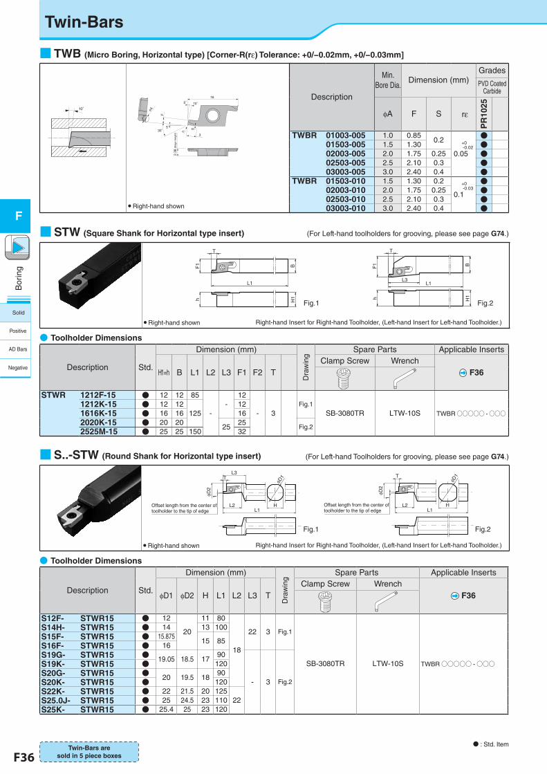
F36 F37
Bor
ing
F
Twin-Bars
N : Std. Item
■ TWB (Micro Boring, Horizontal type) [Corner-R(rε) Tolerance: +0/−0.02mm, +0/−0.03mm]
10°
2.38
3
F
S
r30°5°
5°16
10°
A
(E
dge
Hei
ght)
● Right-hand shown
Twin-Bars are sold in 5 piece boxes
●�Toolholder Dimensions
Description Std.
Dimension (mm)
Dra
win
g
Spare Parts Applicable Inserts
H1=h B L1 L2 L3 F1 F2 TClamp Screw Wrench
F36
STWR 1212F-15 ● 12 12 85
--
12
- 3Fig.1
SB-3080TR LTW-10S TWBR○○○○○ -○○○1212K-15 ● 12 12
12512
1616K-15 ● 16 16 162020K-15 ● 20 20
2525
Fig.22525M-15 ● 25 25 150 32
Description
Min. Bore Dia.
Dimension (mm)Grades
PVD Coated Carbide
φA F S �rε
PR
1025
TWBR 01003-005 1.0 0.850.2 +0
-0.02
0.05
●01503-005 1.5 1.30 ●02003-005 2.0 1.75 0.25 ●02503-005 2.5 2.10 0.3 ●03003-005 3.0 2.40 0.4 ●
TWBR 01503-010 1.5 1.30 0.2 +0 -0.03
0.1
●02003-010 2.0 1.75 0.25 ●02503-010 2.5 2.10 0.3 ●03003-010 3.0 2.40 0.4 ●
●�Toolholder Dimensions
Description Std.
Dimension (mm)
Dra
win
g
Spare Parts Applicable Inserts
φD1 φD2 H L1 L2 L3 TClamp Screw Wrench
F36
S12F- STWR15 ● 12
20
11 80
18
22 3 Fig.1
SB-3080TR LTW-10S TWBR○○○○○ -○○○
S14H- STWR15 ● 14 13 100S15F- STWR15 ● 15.875
15 85S16F- STWR15 ● 16S19G- STWR15 ● 19.05 18.5 17
90
- 3 Fig.2
S19K- STWR15 ● 120S20G- STWR15 ● 20 19.5 18
90S20K- STWR15 ● 120S22K- STWR15 ● 22 21.5 20 125
22S25.0J- STWR15 ● 25 24.5 23 110S25K- STWR15 ● 25.4 25 23 120
■S..-STW (Round Shank for Horizontal type insert)
● Right-hand shown
φD1
L3T T
φD2
φD2
1 1
L2L1
L2L1
H
φD1
HOffset length from the center of toolholder to the tip of edge
Offset length from the center of toolholder to the tip of edge
Fig.1 Fig.2
Right-hand Insert for Right-hand Toolholder, (Left-hand Insert for Left-hand Toolholder.)
(For Left-hand Toolholders for grooving, please see page G74.)
■STW (Square Shank for Horizontal type insert)
Fig.1 Fig.2
L1
BH
1hF
1
T
L1L3
BH
1hF
1
T
(For Left-hand toolholders for grooving, please see page G74.)
● Right-hand shown Right-hand Insert for Right-hand Toolholder, (Left-hand Insert for Left-hand Toolholder.)
Solid
Positive
AD Bars
Negative
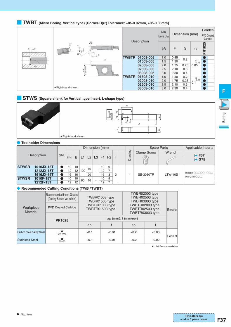
F36 F37
Bor
ing
F
10°
6.4
3
F
Srε30°
16
5°
10°
φA
(Edg
e H
eigh
t)
◆�Recommended Cutting Conditions (TWB / TWBT)
Workpiece Material
Recommended Insert Grades (Cutting Speed Vc: m/min) TWBR01003 type
TWBR01503 type TWBTR01003 type TWBTR01503 type
TWBR02003 type TWBR02503 type TWBR03003 type
TWBTR02003 type TWBTR02503 type TWBTR03003 type
RemarksPVD Coated Carbide
PR1025 ap (mm), f (mm/rev)
ap f ap f
Carbon Steel / Alloy Steel ★30~100 ~0.1 ~0.01 ~0.2 ~0.03
CoolantStainless Steel ★
30~80 ~0.1 ~0.01 ~0.2 ~0.02
★ : 1st Recommendation
■ TWBT (Micro Boring, Vertical type) [Corner-R(rε) Tolerance: +0/−0.02mm, +0/−0.03mm]
● Right-hand shown
■STWS (Square shank for Vertical type insert, L-shape type)
● Right-hand shown
20
F1
F2
L2L1
BHh
T
Description
Min. Bore Dia.
Dimension (mm)Grades
PVD Coated Carbide
φA F S rε
PR
1025
TWBTR 01003-005 1.0 0.850.2 +0
-0.02
0.05
●01503-005 1.5 1.30 ●02003-005 2.0 1.75 0.25 ●02503-005 2.5 2.10 0.3 ●03003-005 3.0 2.30 0.4 ●
TWBTR 01503-010 1.5 1.30 0.2 +0 -0.03
0.1
●02003-010 2.0 1.75 0.25 ●02503-010 2.5 2.10 0.3 ●03003-010 3.0 2.30 0.4 ●
●�Toolholder Dimensions
Description Std.
Dimension (mm)
Dra
win
g
Spare Parts Applicable Inserts
H1=h B L1 L2 L3 F1 F2 TClamp Screw Wrench
F37G75
STWSR 1010JX-15T ● 10 10120
16-
10 9
3 - SB-3080TR LTW-10STWBTR○○○○○ -○○○
TWFGTR○○○
1212JX-15T ● 12 12 12 71616JX-15T ● 16 16 20 16 3
STWSR 1010F-15T ● 10 1085 16 -
10 91212F-15T ● 12 12 12 7
Twin-Bars are sold in 5 piece boxes
N : Std. Item
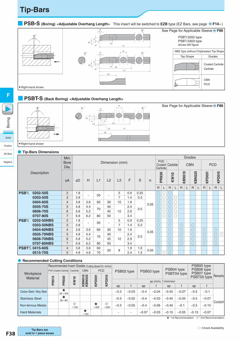
F38 F39
Bor
ing
F
○ :Check Availability
■ PSB-S (Boring) <Adjustable Overhang Length>� This insert will be switched to EZB type (EZ Bars, see page F14~ )
■PSBT-S (Back Boring) <Adjustable Overhang Length>
5° 5°
1.5
φA
15°
L1
L3
H
L2
S
φD
F
rε
● Right-hand shown
●�Tip-Bars Dimensions
5゜
5゜
F
15゜
rεF
15°
φA
rε
L2
L3
S
L1
S
H
L1
φDφD
5°
● Right-hand shown
−NBS Type (without Chipbreaker) Top Shape
Top Shape Grades
Coated Carbide
Carbide
CBN�PCD
Description
Min. Bore Dia.
Dimension (mm)Grades
PVD Coated Carbide
Carbide CBN PCD
φA φD H L1 L2 L3 F S rε PR
930
KW
10
KB
N51
0
KB
N52
5
KP
D00
1
KP
D01
0
R L R L R L R L R L R L
PSB& 0202-50S 2 1.8- 50 -
5 0.9 0.25
0.05
○ ○ ○0303-50S 3 2.8 7 1.4 0.3 ○ ○ ○ ○0404-60S 4 3.8 3.6 60 30 10 1.9
0.5
○ ○ ○ ○0505-70S 5 4.8 4.4
7040
122.4 ○ ○ ○ ○
0606-70S 6 5.8 5.2 45 2.9 ○ ○ ○ ○0707-80S 7 6.8 6.2 80 50 3.4 ○ ○ ○ ○
PSB& 0202-50NBS 2 1.8- 50 -
5 0.9 0.25
0.05
○ ○0303-50NBS 3 2.8 7 1.4 0.3 ○ ○ ○ ○0404-60NBS 4 3.8 3.6 60 30 10 1.9
0.5
○ ○ ○ ○ ○ ○0505-70NBS 5 4.8 4.4
7040
122.4 ○ ○ ○ ○ ○ ○ ○
0606-70NBS 6 5.8 5.2 45 2.9 ○ ○ ○ ○ ○ ○0707-80NBS 7 6.8 6.2 80 50 3.4 ○ ○ ○ ○ ○ ○
PSBT& 0415-60S 4 3.8 3.6 6020 8
1.9 1.00.05
○ ○0515-70S 5 4.8 4.6 70 2.4 1.3 ○ ○ ○
Tip-Bars are sold in 1 piece boxes
See Page for Applicable Sleeve F86
See Page for Applicable Sleeve F86
◆�Recommended Cutting Conditions
Workpiece Material
Recommended Insert Grades (Cutting Speed Vc: m/min)
PSB02 type PSB03 type PSB04 typePSBT04 type
PSB05 typePSB06 typePSB07 type
PSBT05 type Remarks
PVD Coated Carbide Carbide CBN PCD
PR
915
PR
930
KW
10
KB
N51
0K
BN
525
KP
D0
01
KP
D01
0
ap (mm), f (mm/rev)
ap f ap f ap f ap f
Carbon Steel / Alloy Steel ★ 30~100
~0.3 ~0.03 ~0.4 ~0.04 ~0.45 ~0.07 ~0.5 ~0.1
CoolantStainless Steel ★�
30~80~0.3 ~0.02 ~0.4 ~0.03 ~0.45 ~0.05 ~0.5 ~0.07
Non-ferrous Metals ☆ ~100
★ ~300
☆ ~300
~0.3 ~0.05 ~0.4 ~0.06 ~0.45 ~0.1 ~0.5 ~0.15
Hard Materials ★ ~100
- - ~0.07 ~0.03 ~0.10 ~0.05 ~0.15 ~0.07
★:1st Recommendation ☆:2nd Recommendation
Tip-Bars
PSB&0202 typePSB&0303 type shows left figure
Solid
Positive
AD Bars
Negative
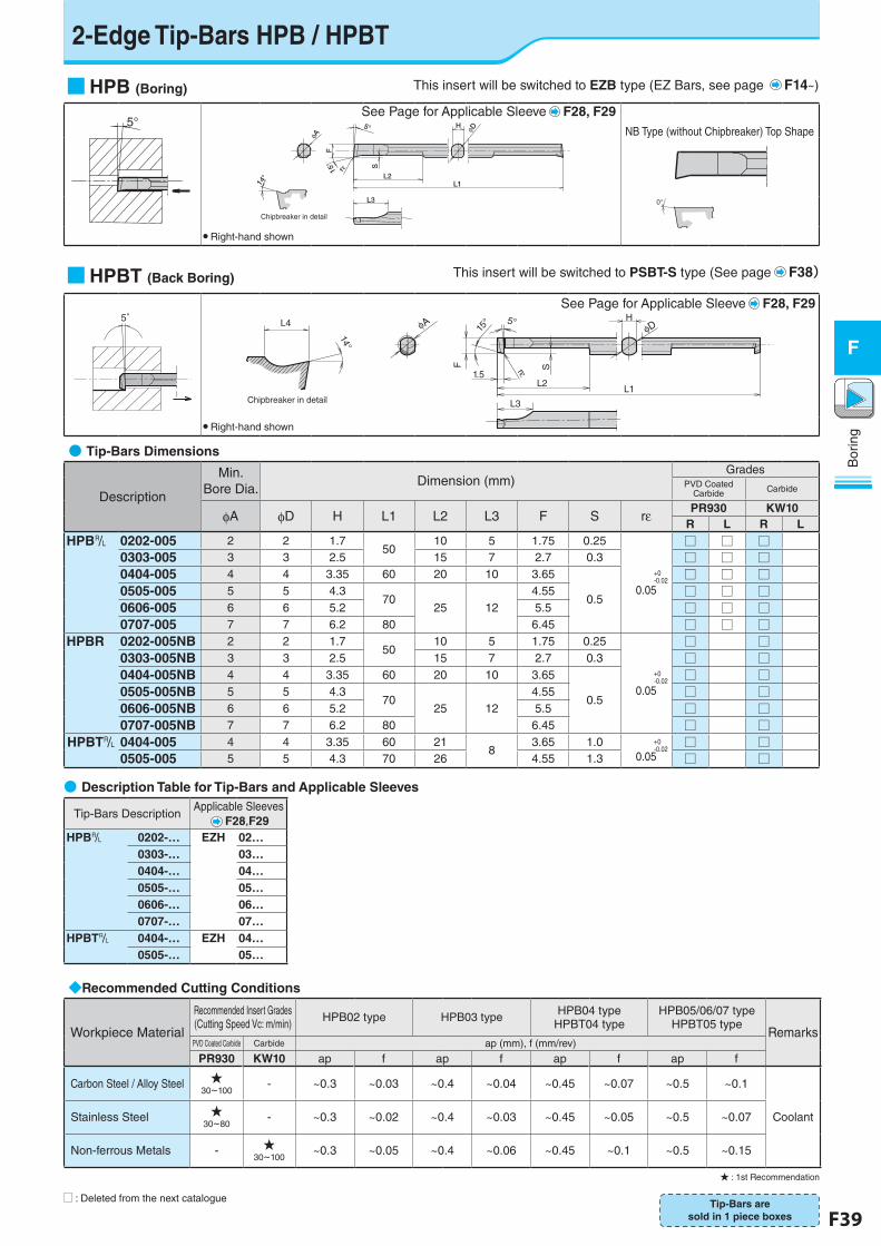
F38 F39
Bor
ing
F
2-Edge Tip-Bars HPB / HPBT
■HPB (Boring)
�
H
15°
5°
L2L1
L3
F
S
φA
φD
rε
14°
Chipbreaker in detail
NB Type (without Chipbreaker) Top Shape
0°
● Right-hand shown
■HPBT (Back Boring)
5°φA
L3
S
1.5
F
L2
15° 5° H
φD
L1
rε
L4
14°
Chipbreaker in detail
● Right-hand shown
●�Tip-Bars Dimensions
Description
Min. Bore Dia.
Dimension (mm)Grades
PVD Coated Carbide Carbide
φA φD H L1 L2 L3 F S rε PR930 KW10R L R L
HPB& 0202-005 2 2 1.750
10 5 1.75 0.25
+0-0.02
0.05
□ □ □0303-005 3 3 2.5 15 7 2.7 0.3 □ □ □0404-005 4 4 3.35 60 20 10 3.65
0.5
□ □ □0505-005 5 5 4.3
7025 12
4.55 □ □ □0606-005 6 6 5.2 5.5 □ □ □0707-005 7 7 6.2 80 6.45 □ □ □
HPBR 0202-005NB 2 2 1.750
10 5 1.75 0.25
+0-0.02
0.05
□ □0303-005NB 3 3 2.5 15 7 2.7 0.3 □ □0404-005NB 4 4 3.35 60 20 10 3.65
0.5
□ □0505-005NB 5 5 4.3
7025 12
4.55 □ □0606-005NB 6 6 5.2 5.5 □ □0707-005NB 7 7 6.2 80 6.45 □ □
HPBT& 0404-005 4 4 3.35 60 218
3.65 1.0 +0-0.02
0.05□ □
0505-005 5 5 4.3 70 26 4.55 1.3 □ □
◆Recommended Cutting Conditions
Workpiece Material
Recommended Insert Grades(Cutting Speed Vc: m/min) HPB02 type HPB03 type HPB04 type
HPBT04 typeHPB05/06/07 type
HPBT05 typeRemarks
PVD Coated Carbide Carbide ap (mm), f (mm/rev)
PR930 KW10 ap f ap f ap f ap f
Carbon Steel / Alloy Steel ★30~100
- ~0.3 ~0.03 ~0.4 ~0.04 ~0.45 ~0.07 ~0.5 ~0.1
CoolantStainless Steel ★30~80
- ~0.3 ~0.02 ~0.4 ~0.03 ~0.45 ~0.05 ~0.5 ~0.07
Non-ferrous Metals - ★30~100
~0.3 ~0.05 ~0.4 ~0.06 ~0.45 ~0.1 ~0.5 ~0.15
★ : 1st Recommendation
Tip-Bars are sold in 1 piece boxes
U : Deleted from the next catalogue
Tip-Bars DescriptionApplicable Sleeves
F28,F29HPB& 0202-… EZH 02…
0303-… 03…0404-… 04…0505-… 05…0606-… 06…0707-… 07…
HPBT& 0404-… EZH 04…0505-… 05…
This insert will be switched to EZB type (EZ Bars, see page F14~)
This insert will be switched to PSBT-S type (See page F38)
Tip-Bars
See Page for Applicable Sleeve F28, F29
See Page for Applicable Sleeve F28, F29
5°
●�Description Table for Tip-Bars and Applicable Sleeves
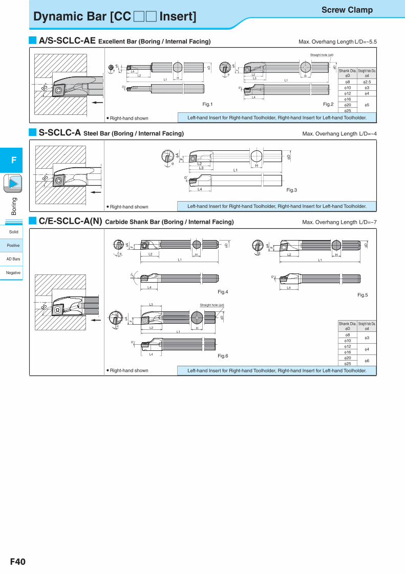
F40 F41
Bor
ing
F
Dynamic Bar [CC□□ Insert]
■A/S-SCLC-AE Excellent Bar (Boring / Internal Facing) Max. Overhang Length L/D=~5.5
Screw Clamp
Shank Dia. φD
Straight hole Dia.φd
φ8 φ2.5φ10 φ3φ12 φ4φ16
φ5φ20φ25
● Right-hand shown
Fig.1 Fig.2
L2
L1
H
F
L1L2
L4
H
F
HL1
L2L3
L4
FφD φD
θ
5°
φD
φA φA
φA
L6
L5
0°
θ
0°
θ
Straight hole (φd)
95゚
■S-SCLC-A Steel Bar (Boring / Internal Facing) Max. Overhang Length�L/D=~4
● Right-hand shown Left-hand Insert for Right-hand Toolholder, Right-hand Insert for Left-hand Toolholder.
Fig.3
L2
L1H
F
HL1
L2L3
L4
F
θ
φD
θ
5°
φDφA φA
L6
L5
0° 5°
■C/E-SCLC-A(N) Carbide Shank Bar (Boring / Internal Facing) Max. Overhang Length�L/D=~7
● Right-hand shown
Shank Dia.φD
Straight hole Dia.φd
φ8φ3
φ10φ12
φ4φ16 φ20
φ6φ25
Left-hand Insert for Right-hand Toolholder, Right-hand Insert for Left-hand Toolholder.
H
φD
L2
φA F
θ
L4
0°
C04G-SCLC&03-05Aのみ2°
L1
F
HL2
L3
L1
L4
0°
Straight hole ( d)
DA
Fig.5
L1
L2
φDF
θ H
L4
φA2°
Fig.4
Fig.6
C/E-SCLC-A型 F24
95゚
Left-hand Insert for Right-hand Toolholder, Right-hand Insert for Left-hand Toolholder.
95゚
Screw Clamp
Solid
Positive
AD Bars
Negative
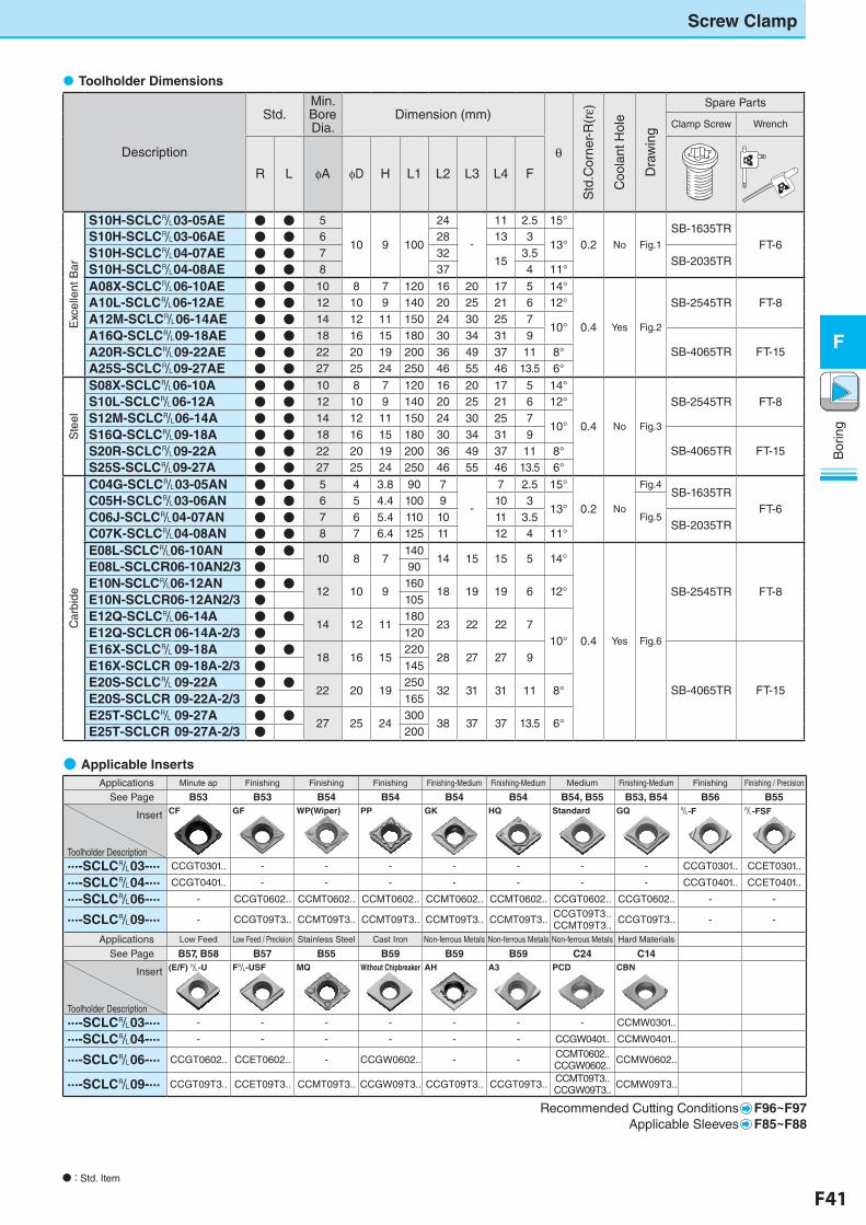
F40 F41
Bor
ing
F
Description
Std.Min. Bore Dia.
Dimension (mm)
θ
Std
.Cor
ner-
R(rε)
Coo
lant
Hol
e
Dra
win
g
Spare Parts
Clamp Screw Wrench
R L φA φD H L1 L2 L3 L4 F
Exc
elle
nt B
ar
S10H-SCLC&03-05AE ● ● 5
10 9 100
24
‐
11 2.5 15°
0.2 No Fig.1
SB-1635TRFT-6
S10H-SCLC&03-06AE ● ● 6 28 13 313°
S10H-SCLC&04-07AE ● ● 7 3215
3.5SB-2035TR
S10H-SCLC&04-08AE ● ● 8 37 4 11°
A08X-SCLC&06-10AE ● ● 10 8 7 120 16 20 17 5 14°
0.4 Yes Fig.2
SB-2545TR FT-8A10L-SCLC&06-12AE ● ● 12 10 9 140 20 25 21 6 12°
A12M-SCLC&06-14AE ● ● 14 12 11 150 24 30 25 710°
A16Q-SCLC&09-18AE ● ● 18 16 15 180 30 34 31 9SB-4065TR FT-15A20R-SCLC&09-22AE ● ● 22 20 19 200 36 49 37 11 8°
A25S-SCLC&09-27AE ● ● 27 25 24 250 46 55 46 13.5 6°
Ste
el
S08X-SCLC&06-10A ● ● 10 8 7 120 16 20 17 5 14°
0.4 No Fig.3
SB-2545TR FT-8S10L-SCLC&06-12A ● ● 12 10 9 140 20 25 21 6 12°
S12M-SCLC&06-14A ● ● 14 12 11 150 24 30 25 710°
S16Q-SCLC&09-18A ● ● 18 16 15 180 30 34 31 9SB-4065TR FT-15S20R-SCLC&09-22A ● ● 22 20 19 200 36 49 37 11 8°
S25S-SCLC&09-27A ● ● 27 25 24 250 46 55 46 13.5 6°
Car
bide
C04G-SCLC&03-05AN ● ● 5 4 3.8 90 7
‐
7 2.5 15°
0.2 No
Fig.4SB-1635TR
FT-6C05H-SCLC&03-06AN ● ● 6 5 4.4 100 9 10 3
13°Fig.5C06J-SCLC&04-07AN ● ● 7 6 5.4 110 10 11 3.5
SB-2035TRC07K-SCLC&04-08AN ● ● 8 7 6.4 125 11 12 4 11°
E08L-SCLC&06-10AN ● ●10 8 7
14014 15 15 5 14°
0.4 Yes Fig.6
SB-2545TR FT-8
E08L-SCLCR06-10AN2/3 ● 90
E10N-SCLC&06-12AN ● ●12 10 9
16018 19 19 6 12°
E10N-SCLCR06-12AN2/3 ● 105
E12Q-SCLC&�06-14A ● ●14 12 11
18023 22 22 7
10°E12Q-SCLCR�06-14A-2/3 ● 120
E16X-SCLC&�09-18A ● ●18 16 15
22028 27 27 9
SB-4065TR FT-15
E16X-SCLCR�09-18A-2/3 ● 145
E20S-SCLC&�09-22A ● ●22 20 19
25032 31 31 11 8°
E20S-SCLCR�09-22A-2/3 ● 165
E25T-SCLC&�09-27A ● ●27 25 24
30038 37 37 13.5 6°
E25T-SCLCR�09-27A-2/3 ● 200
�Toolholder Dimensions
Screw Clamp
● Applicable Inserts
Applications Minute ap Finishing Finishing Finishing Finishing-Medium Finishing-Medium Medium Finishing-Medium Finishing Finishing / Precision
See Page B53 B53 B54 B54 B54 B54 B54, B55 B53, B54 B56 B55
Insert
Toolholder Description
CF GF WP(Wiper) PP GK HQ Standard GQ &-F &-FSF
...-SCLC&03-... CCGT0301.. - - - - - - - CCGT0301.. CCET0301..
...-SCLC&04-... CCGT0401.. - - - - - - - CCGT0401.. CCET0401..
...-SCLC&06-... - CCGT0602.. CCMT0602.. CCMT0602.. CCMT0602.. CCMT0602.. CCGT0602.. CCGT0602.. - -
...-SCLC&09-... - CCGT09T3.. CCMT09T3.. CCMT09T3.. CCMT09T3.. CCMT09T3.. CCGT09T3..CCMT09T3.. CCGT09T3.. - -
Applications Low Feed Low Feed / Precision Stainless Steel Cast Iron Non-ferrous Metals Non-ferrous Metals Non-ferrous Metals Hard Materials
See Page B57, B58 B57 B55 B59 B59 B59 C24 C14
Insert
Toolholder Description
(E/F) &-U F&-USF MQ Without Chipbreaker AH A3 PCD CBN
...-SCLC&03-... - - - - - - - CCMW0301..
...-SCLC&04-... - - - - - - CCGW0401.. CCMW0401..
...-SCLC&06-... CCGT0602.. CCET0602.. - CCGW0602.. - - CCMT0602..CCGW0602.. CCMW0602..
...-SCLC&09-... CCGT09T3.. CCET09T3.. CCMT09T3.. CCGW09T3.. CCGT09T3.. CCGT09T3.. CCMT09T3..CCGW09T3.. CCMW09T3..
Recommended Cutting Conditions F96~F97Applicable Sleeves F85~F88
N�: Std. Item
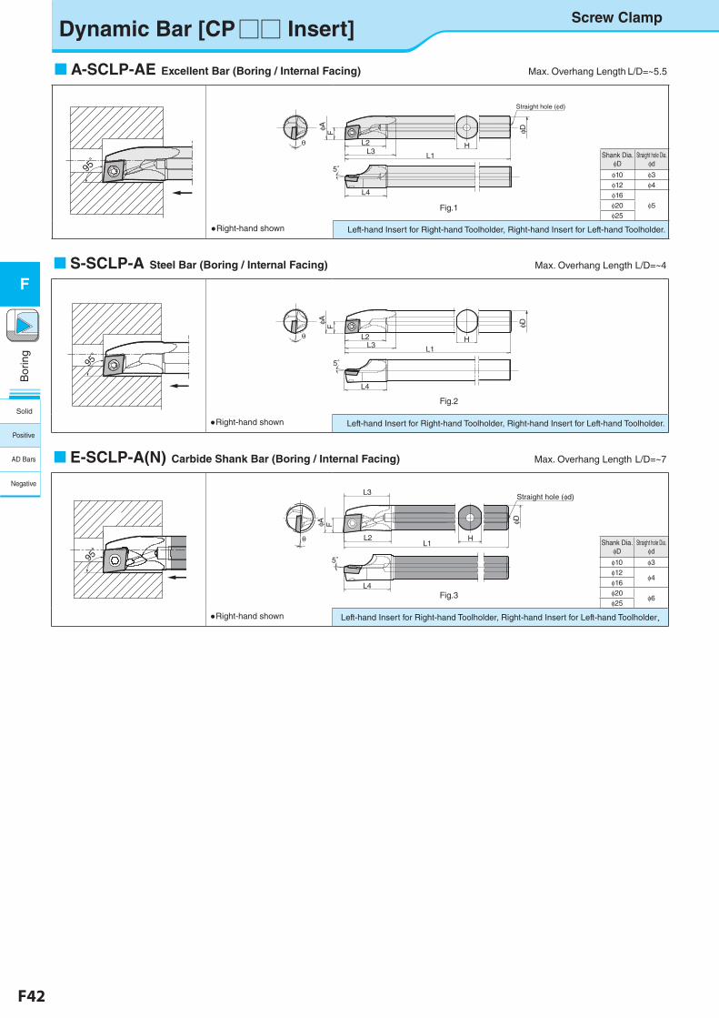
F42 F43
Bor
ing
F
Shank Dia. φD
Straight hole Dia.φd
φ10 φ3φ12 φ4φ16
φ5φ20φ25
Shank Dia.φD
Straight hole Dia.φd
φ10 φ3φ12
φ4φ16 φ20
φ6φ25
Dynamic Bar [CP□□ Insert]
Fig.1
S-SCLP-A Steel Bar (Boring / Internal Facing) Max. Overhang Length L/D=~4
95゚
●Right-hand shown Left-hand Insert for Right-hand Toolholder, Right-hand Insert for Left-hand Toolholder.
Fig.2
E-SCLP-AE型(E12Q-SCLPR08-14A) F26 fig3
HL2
F
L3
L1
L4
Straight hole (φd)
φDφA
θ
5°
Screw Clamp
L2
L1H
Fθ
φDφA
L4
L3
5°
L2
L1H
F φDφA
L4
L3
5°
Straight hole (φd)
θ
Fig.3
A-SCLP-AE Excellent Bar (Boring / Internal Facing) Max. Overhang Length L/D=~5.5
95゚
●Right-hand shown Left-hand Insert for Right-hand Toolholder, Right-hand Insert for Left-hand Toolholder.
E-SCLP-A(N) Carbide Shank Bar (Boring / Internal Facing) Max. Overhang Length�L/D=~7
95゚
●Right-hand shown Left-hand Insert for Right-hand Toolholder, Right-hand Insert for Left-hand Toolholder.
Solid
Positive
AD Bars
Negative
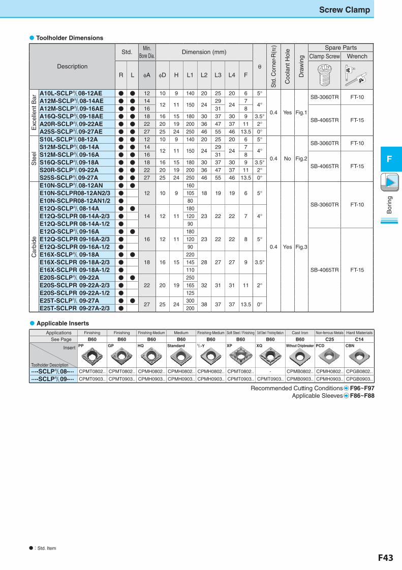
F42 F43
Bor
ing
F
N�:�Std. Item
Description
Std.Min.
Bore Dia.Dimension (mm)
θ
Std
. Cor
ner-R
(rε)
Coo
lant
Hol
e
Dra
win
g
Spare PartsClamp Screw Wrench
R L φA φD H L1 L2 L3 L4 F
Exc
elle
nt B
ar
A10L-SCLP&08-12AE ● ● 12 10 9 140 20 25 20 6 5°
0.4 Yes Fig.1
SB-3060TR FT-10A12M-SCLP&08-14AE ● ● 14
12 11 150 2429
247
4°A12M-SCLP&09-16AE ● ● 16 31 8
SB-4065TR FT-15A16Q-SCLP&09-18AE ● ● 18 16 15 180 30 37 30 9 3.5°
A20R-SCLP&09-22AE ● ● 22 20 19 200 36 47 37 11 2°
A25S-SCLP&09-27AE ● ● 27 25 24 250 46 55 46 13.5 0°
Ste
el
S10L-SCLP&08-12A ● ● 12 10 9 140 20 25 20 6 5°
0.4 No Fig.2
SB-3060TR FT-10S12M-SCLP&08-14A ● ● 14
12 11 150 2429
247
4°S12M-SCLP&09-16A ● ● 16 31 8
SB-4065TR FT-15S16Q-SCLP&09-18A ● ● 18 16 15 180 30 37 30 9 3.5°
S20R-SCLP&09-22A ● ● 22 20 19 200 36 47 37 11 2°
S25S-SCLP&09-27A ● ● 27 25 24 250 46 55 46 13.5 0°
Car
bide
E10N-SCLP&08-12AN ● ●12 10 9
16018 19 19 6 5°
0.4 Yes Fig.3
SB-3060TR FT-10
E10N-SCLPR08-12AN2/3 ● 105
E10N-SCLPR08-12AN1/2 ● 80
E12Q-SCLP&�08-14A ● ●14 12 11
18023 22 22 7 4°E12Q-SCLPR�08-14A-2/3 ● 120
E12Q-SCLPR�08-14A-1/2 ● 90
E12Q-SCLP&�09-16A ● ●16 12 11
18023 22 22 8 5°
SB-4065TR FT-15
E12Q-SCLPR�09-16A-2/3 ● 120
E12Q-SCLPR�09-16A-1/2 ● 90
E16X-SCLP&�09-18A ● ●18 16 15
22028 27 27 9 3.5°E16X-SCLPR�09-18A-2/3 ● 145
E16X-SCLPR�09-18A-1/2 ● 110
E20S-SCLP&�09-22A ● ●22 20 19
25032 31 31 11 2°E20S-SCLPR�09-22A-2/3 ● 165
E20S-SCLPR�09-22A-1/2 ● 125
E25T-SCLP&�09-27A ● ●27 25 24
30038 37 37 13.5 0°
E25T-SCLPR�09-27A-2/3 ● 200
Toolholder Dimensions
Applicable InsertsApplications Finishing Finishing Finishing-Medium Medium Finishing-Medium Soft Steel / Finishing Soft Steel / Finishing-Medium Cast Iron Non-ferrous Metals Hard Materials
See Page B60 B60 B60 B60 B60 B60 B60 B60 C25 C14
Insert
Toolholder Description
PP GP HQ Standard &-Y XP XQ Without Chipbreaker PCD CBN
...-SCLP&08-... CPMT0802.. CPMT0802.. CPMH0802.. CPMH0802.. CPMH0802.. CPMT0802.. - CPMB0802.. CPMH0802.. CPGB0802..
...-SCLP&09-... CPMT0903.. CPMT0903.. CPMH0903.. CPMH0903.. CPMH0903.. CPMT0903.. CPMT0903.. CPMB0903.. CPMH0903.. CPGB0903..
Recommended Cutting Conditions F96~F97Applicable Sleeves F86~F88
Screw Clamp
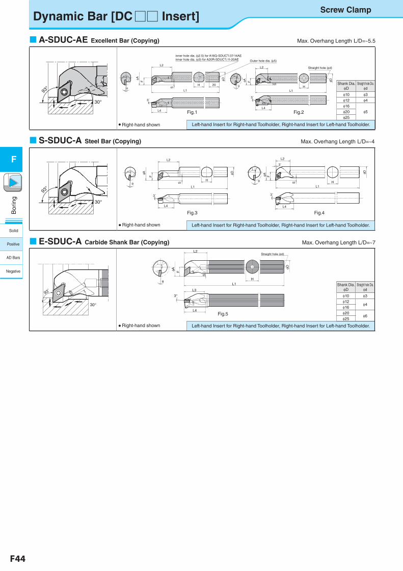
F44 F45
Bor
ing
F
Shank Dia.�φD
Straight hole Dia.φd
φ10 φ3φ12 φ4φ16
φ5φ20φ25
Shank Dia.�φD
Straight hole Dia.φd
φ10 φ3φ12
φ4φ16 φ20
φ6φ25
Dynamic Bar [DC□□ Insert]
A-SDUC-AE Excellent Bar (Copying) Max. Overhang Length�L/D=~5.5
● Right-hand shown
F
φA
H 20
φD
L1
L2
Sθ
S
L1H
L2
θ
FφA φD
Straight hole (φd)
L4L4
3˚3˚
Outer hole dia. (φ5)
inner hole dia. (φ2.5) for A16Q-SDUC&07-14AEinner hole dia. (φ3) for A20R-SDUC&11-20AE
Left-hand Insert for Right-hand Toolholder, Right-hand Insert for Left-hand Toolholder.
Fig.1 Fig.2�
30°
93°
S-SDUC-A Steel Bar (Copying) Max. Overhang Length�L/D=~4
● Right-hand shown Left-hand Insert for Right-hand Toolholder, Right-hand Insert for Left-hand Toolholder.
Fig.3 Fig.4
θ
F
φA
H
φD
L1
L2
L4 L4
S
L1H
L2
3˚
θ
FφA
φD
3˚ 3˚
S
E-SDUC-A Carbide Shank Bar (Copying) Max. Overhang Length L/D=~7
● Right-hand shown Left-hand Insert for Right-hand Toolholder, Right-hand Insert for Left-hand Toolholder.
Fig.5
E-SDUC-A型(E16X-SDUCR07-20A) F28 fig5
φD
H
L2
S
L1
FφA
θ
3°
L4
L3
Straight hole (φd)
φA
Screw Clamp
30°
93°
30°
93゚
Solid
Positive
AD Bars
Negative
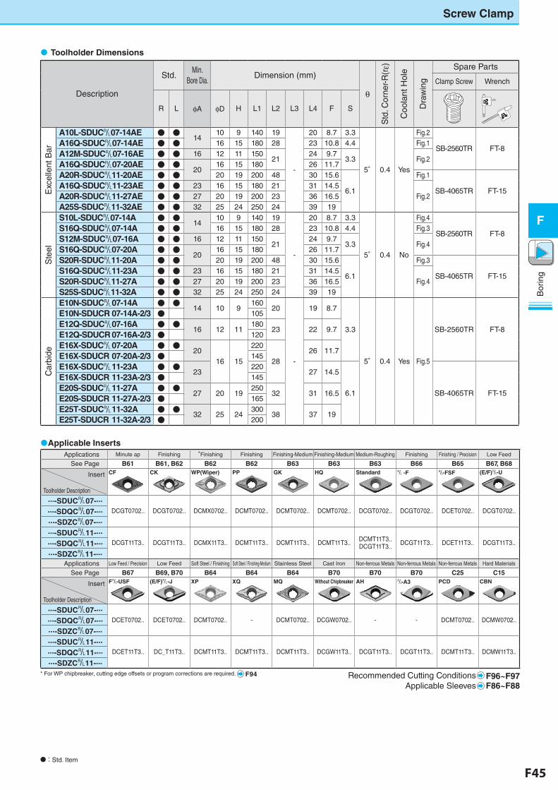
F44 F45
Bor
ing
F
Applications Minute ap Finishing *Finishing Finishing Finishing-Medium Finishing-Medium Medium-Roughing Finishing Finishing / Precision Low Feed
See Page B61 B61, B62 B62 B62 B63 B63 B63 B66 B65 B67, B68
Insert
Toolholder Description
CF CK WP(Wiper) PP GK HQ Standard &�-F &-FSF (E/F)&-U
...-SDUC&07-...
DCGT0702.. DCGT0702.. DCMX0702.. DCMT0702.. DCMT0702.. DCMT0702.. DCGT0702.. DCGT0702.. DCET0702.. DCGT0702.....-SDQC&07-......-SDZC&07-......-SDUC&11-...
DCGT11T3.. DCGT11T3.. DCMX11T3.. DCMT11T3.. DCMT11T3.. DCMT11T3.. DCMT11T3..DCGT11T3.. DCGT11T3.. DCET11T3.. DCGT11T3.....-SDQC&11-...
...-SDZC&11-...Applications Low Feed / Precision Low Feed Soft Steel / Finishing Soft Steel / Finishing-Medium Stainless Steel Cast Iron Non-ferrous Metals Non-ferrous Metals Non-ferrous Metals Hard Materials
See Page B67 B69, B70 B64 B64 B64 B70 B70 B70 C25 C15
Insert
Toolholder Description
F&-USF (E/F)&-J XP XQ MQ Without Chipbreaker AH &-A3 PCD CBN
...-SDUC&07-...
DCET0702.. DCET0702.. DCMT0702.. - DCMT0702.. DCGW0702.. - - DCMT0702.. DCMW0702.....-SDQC&07-......-SDZC&07-......-SDUC&11-...
DCET11T3.. DC_T11T3.. DCMT11T3.. DCMT11T3.. DCMT11T3.. DCGW11T3.. DCGT11T3.. DCGT11T3.. DCMT11T3.. DCMW11T3.....-SDQC&11-......-SDZC&11-...
Recommended Cutting Conditions F96~F97Applicable Sleeves F86~F88
Applicable Inserts
�Toolholder Dimensions
Description
Std. Min.
Bore Dia.Dimension (mm)
θ
Std
. Cor
ner-R
(rε)
Coo
lant
Hol
e
Dra
win
g
Spare Parts
Clamp Screw Wrench
R L φA φD H L1 L2 L3 L4 F S
Exc
elle
nt B
ar
A10L-SDUC&07-14AE ● ●14
10 9 140 19
-
20 8.7 3.3
5° 0.4 Yes
Fig.2
SB-2560TR FT-8A16Q-SDUC&07-14AE ● ● 16 15 180 28 23 10.8 4.4 Fig.1
A12M-SDUC&07-16AE ● ● 16 12 11 15021
24 9.73.3 Fig.2
A16Q-SDUC&07-20AE ● ●20
16 15 180 26 11.7
A20R-SDUC&11-20AE ● ● 20 19 200 48 30 15.6
6.1
Fig.1
SB-4065TR FT-15A16Q-SDUC&11-23AE ● ● 23 16 15 180 21 31 14.5
Fig.2A20R-SDUC&11-27AE ● ● 27 20 19 200 23 36 16.5
A25S-SDUC&11-32AE ● ● 32 25 24 250 24 39 19
Ste
el
S10L-SDUC&07-14A ● ●14
10 9 140 19
-
20 8.7 3.3
5° 0.4 No
Fig.4
SB-2560TR FT-8S16Q-SDUC&07-14A ● ● 16 15 180 28 23 10.8 4.4 Fig.3
S12M-SDUC&07-16A ● ● 16 12 11 15021
24 9.73.3 Fig.4
S16Q-SDUC&07-20A ● ●20
16 15 180 26 11.7
S20R-SDUC&11-20A ● ● 20 19 200 48 30 15.6
6.1
Fig.3
SB-4065TR FT-15S16Q-SDUC&11-23A ● ● 23 16 15 180 21 31 14.5
Fig.4S20R-SDUC&11-27A ● ● 27 20 19 200 23 36 16.5
S25S-SDUC&11-32A ● ● 32 25 24 250 24 39 19
Car
bide
E10N-SDUC&�07-14A ● ●14 10 9
16020
-
19 8.7
3.3
5° 0.4 Yes Fig.5
SB-2560TR FT-8
E10N-SDUCR�07-14A-2/3 ● 105
E12Q-SDUC&�07-16A ● ●16 12 11
18023 22 9.7
E12Q-SDUCR�07-16A-2/3 ● 120
E16X-SDUC&�07-20A ● ●20
16 15
220
2826 11.7
E16X-SDUCR�07-20A-2/3 ● 145
E16X-SDUC&�11-23A ● ●23
22027 14.5
6.1 SB-4065TR FT-15
E16X-SDUCR�11-23A-2/3 ● 145
E20S-SDUC&�11-27A ● ●27 20 19
25032 31 16.5
E20S-SDUCR�11-27A-2/3 ● 165
E25T-SDUC&�11-32A ● ●32 25 24
30038 37 19
E25T-SDUCR�11-32A-2/3 ● 200
Screw Clamp
* For WP chipbreaker, cutting edge offsets or program corrections are required. F94
N�:�Std. Item
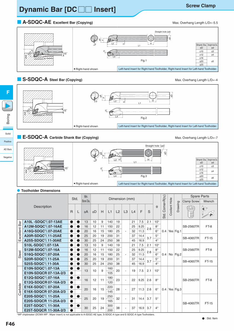
F46 F47
Bor
ing
F
Shank Dia.�φD
Straight hole Dia.φd
φ10 φ3φ12
φ4φ16 φ20
φ6φ25
Shank Dia. φD
Straight hole Dia.φd
φ10 φ3φ12 φ4φ16
φ5φ20φ25
Dynamic Bar [DC□□ Insert]
N�: Std. Item
�Toolholder Dimensions
A-SDQC-AE Excellent Bar (Copying) Max. Overhang Length L/D=~5.5
● Right-hand shown
Left-hand Insert for Right-hand Toolholder, Right-hand Insert for Left-hand Toolholder.
S-SDQC-A Steel Bar (Copying) Max. Overhang Length L/D=~4
● Right-hand shown
E-SDQC-A Carbide Shank Bar (Copying) Max. Overhang Length L/D=~7
Fig.1
Fig.2
Fig.3
Description
Std. Min. Bore Dia.
Dimension (mm)
θ
Std
. Cor
ner-R
(rε)
Coola
nt H
ole
Dra
win
g
Spare PartsClamp Screw Wrench
R L φA φD H L1 L2 L3 L4 F S
Exc
elle
nt B
ar A10L -SDQC&07-13AE ● ● 13 10 9 140 19
-
21 7.5 2.1 10°
0.4 Yes Fig.1
SB-2560TR FT-8A12M-SDQC&07-16AE ● ● 16 12 11 150 22 25 9.252.6
8°
A16Q-SDQC&07-20AE ● ● 20 16 15 180 25 32 11.3 6°
A20R-SDQC&11-25AE ● ● 25 20 19 200 31 37 14.43.7
5°SB-4065TR FT-15
A25S-SDQC&11-30AE ● ● 30 25 24 250 38 45 16.9 4°
Ste
el
S10L-SDQC&07-13A ● ● 13 10 9 140 19
-
21 7.5 2.1 10°
0.4 No Fig.2
SB-2560TR FT-8S12M-SDQC&07-16A ● ● 16 12 11 150 22 25 9.252.6
8°
S16Q-SDQC&07-20A ● ● 20 16 15 180 25 32 11.3 6°
S20R-SDQC&11-25A ● ● 25 20 19 200 31 37 14.43.7
5°SB-4065TR FT-15
S25S-SDQC&11-30A ● ● 30 25 24 250 38 45 16.9 4°
Car
bide
E10N-SDQC&�07-13A ● ●13 10 9
16020 - 19 7.5 2.1 10°
0.4 Yes Fig.3
SB-2560TR FT-8
E10N-SDQCR�07-13A-2/3 ● 105
E12Q-SDQC&�07-16A ● ●16 12 11
18023 - 22 9.25 2.6 8°
E12Q-SDQCR�07-16A-2/3 ● 120
E16X-SDQC&�07-20A ● ●20 16 15
22028 - 27 11.3 2.6 6°
E16X-SDQCR�07-20A-2/3 ● 145
E20S-SDQC&�11-25A ● ●25 20 19
25032 - 31 14.4 3.7 5°
SB-4065TR FT-15E20S-SDQCR�11-25A-2/3 ● 165
E25T-SDQC&�11-30A ● ●30 25 24
30038 - 37 16.9 3.7 4°
E25T-SDQCR�11-30A-2/3 ● 200
● Right-hand shown
A-SDQC-AE型 F30
15゚107.
5゚
107.
5゚
S-SDQC-A型 F30
15゚107.
5゚
107.
5゚
E-SDQC-A型 F30
117.
5゚
107.
5゚15゚
θ L2FφA φD
L1
L4
0°
HS
Screw Clamp
Left-hand Insert for Right-hand Toolholder, Right-hand Insert for Left-hand Toolholder.
Left-hand Insert for Right-hand Toolholder, Right-hand Insert for Left-hand Toolholder.
A-SDQC-AE型(A16Q-SDQCR07-20AE)
F
F30 fig1
θ
φA
L2 H
φD
L1
S
L4
Straight hole (φd)
0°
φD
HL1
L2
FφA
θ
0°
L4
Straight hole (φd)
S
*WP chipbreaker (DCMX-WP : Wiper insert) is not applicable to A-SDQC-AE type, S-SDQC-A type and E-SDQC-A type Toolholders.
Solid
Positive
AD Bars
Negative
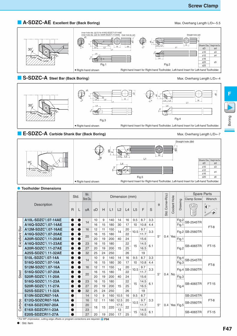
F46 F47
Bor
ing
F
Right-hand Insert for Right-hand Toolholder, Left-hand Insert for Left-hand Toolholder.
Shank Dia. φD
Straight hole Dia.φd
φ10 φ3φ12 φ4φ16
φ5φ20φ25
Shank Dia. φD
Straight hole Dia.φd
φ10 φ3φ12
φ4φ16 φ20 φ6
Screw Clamp
A-SDZC-AE Excellent Bar (Back Boring) Max. Overhang Length L/D=~5.5
● Right-hand shown
Right-hand Insert for Right-hand Toolholder, Left-hand Insert for Left-hand Toolholder.
S-SDZC-A Steel Bar (Back Boring) Max. Overhang Length L/D=~4
● Right-hand shown
E-SDZC-A Carbide Shank Bar (Back Boring) Max. Overhang Length L/D=~7
�Toolholder Dimensions�
Description
Std.Min.
Bore Dia.Dimension (mm)
θ
Std
. Cor
ner-R
(rε)
Coo
lant
Hol
e
Dra
win
g
Spare PartsClamp Screw Wrench
R L φA φD H L1 L2 L4 L5 F S
Exc
elle
nt B
ar
A10L-SDZC&07-14AE ● ●14
10 9 140 14 16 9.5 8.7 3.3
5° 0.4 Yes
Fig.2SB-2545TR
FT-8A16Q-SDZC&07-14AE ● ● 16 15 180 30 17 10 10.8 4.4 Fig.1
A12M-SDZC&07-16AE ● ● 16 12 11 15014
2010.5
9.73.3 Fig.2 SB-2560TR
A16Q-SDZC&07-20AE ● ●20
16 15 180 22 11.7
A20R-SDZC&11-20AE ● ● 20 19 200 40 24
15
15.6
6.1
Fig.1
SB-4065TR FT-15A16Q-SDZC&11-23AE ● ● 23 16 15 180
15
22 14.5
Fig.2A20R-SDZC&11-27AE ● ● 27 20 19 200 25 16.5
A25S-SDZC&11-32AE ● ● 32 25 24 250 26 19
Ste
el
S10L-SDZC&07-14A ● ●14
10 9 140 14 16 9.5 8.7 3.3
5° 0.4 No
Fig.4SB-2545TR
FT-8S16Q-SDZC&07-14A ● ● 16 15 180 30 17 10 10.8 4.4 Fig.3
S12M-SDZC&07-16A ● ● 16 12 11 15014
2010.5
9.73.3 Fig.4 SB-2560TR
S16Q-SDZC&07-20A ● ●20
16 15 180 22 11.7
S20R-SDZC&11-20A ● ● 20 19 200 40 24
15
15.6
6.1
Fig.3
SB-4065TR FT-15S16Q-SDZC&11-23A ● ● 23 16 15 180
15
22 14.5
Fig.4S20R-SDZC&11-27A ● ● 27 20 19 200 25 16.5
S25S-SDZC&11-32A ● ● 32 25 24 250 26 19
Car
bide
E10N-SDZCR07-14A ● 14 10 9 160 10.5 16 9.5 8.7
3.3
5° 0.4 Yes Fig.5
SB-2545TR
FT-8E12Q-SDZCR07-16A ● 16 12 11 180 12.5 2010.5
9.7SB-2560TR
E16X-SDZCR07-20A ● 2016 15 220
17.522
11.7
E16X-SDZCR11-23A ● 23 1315
14.56.1 SB-4065TR FT-15
E20S-SDZCR11-27A ● 27 20 19 250 17 25 16.5
Fig.1 Fig.2
Fig.3 Fig.4
Fig.5 ● Right-hand shown
A-SDZC-AE型 F31 左
30°93゚
A-SDZC-AE型(A16Q-SDZCRL07-20AE) F31 fig2
φD
HL5 L2
F
L1
L4
φA
3°
Straight hole (φd)
θ
E-SDZC-A型 F31
30°
93゚
S-SDZC-A型 F31 左
30°93゚
φD
H
S
L2L5
F
θ
L4
3°
20
inner hole dia. (φ3) for A20R-SDZC&11-20AE
A-SDZC-AE型(A20R-SDZCRL11-20AE) F31 fig1
inner hole dia. (φ2.5) for A16Q-SDZC&07-14AE
L1
φAOuter hole dia. (φ5)
S-SDZC-A型(S16Q-SDZCRL07-20A) F31 fig4
φD
H
S
L2L5
FφA
θ
L4
3°
L1
S-SDZC-A型(S20R-SDZCRL11-20A) F31 fig3
φD
H
SL2L5
FφA
L1
L4
3°
θ
E-SDZC-A型(E16X-SDZCRL07-20A) F31 fig5
φD
HL2
S
L5L1
FφA
L4
3°
θ
Straight hole (φd)
Right-hand Insert for Right-hand Toolholder, Left-hand Insert for Left-hand Toolholder.
* For WP chipbreaker, cutting edge offsets or program corrections are required. F94N�:�Std. Item
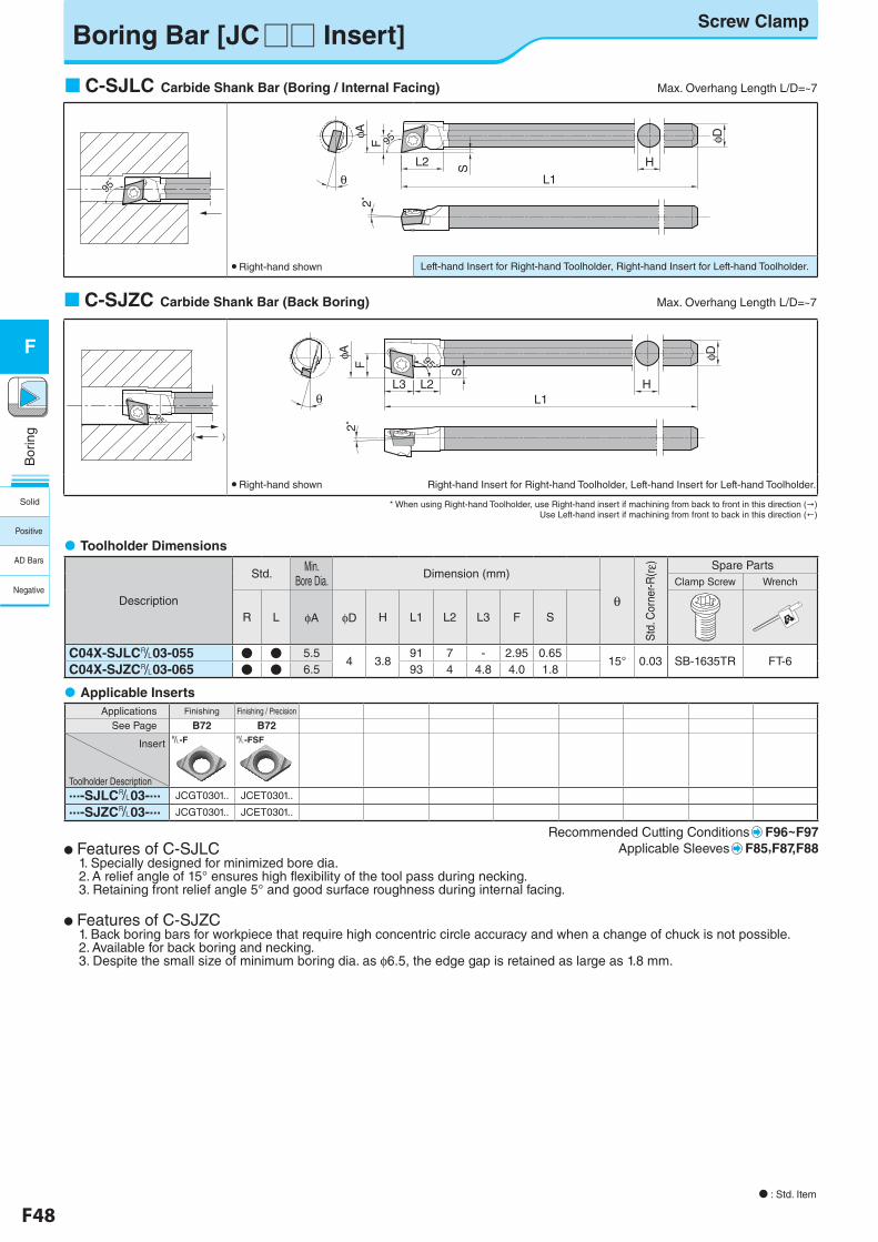
F48 F49
Bor
ing
F
Boring Bar [JC□□ Insert]Screw Clamp
N : Std. Item
C-SJZC Carbide Shank Bar (Back Boring) Max. Overhang Length L/D=~7
C-SJLC Carbide Shank Bar (Boring / Internal Facing) Max. Overhang Length L/D=~7
* When using Right-hand Toolholder, use Right-hand insert if machining from back to front in this direction () Use Left-hand insert if machining from front to back in this direction (!)
�Applicable Inserts
N Features of C-SJLC 1. Specially designed for minimized bore dia. 2. A relief angle of 15° ensures high flexibility of the tool pass during necking. 3. Retaining front relief angle 5° and good surface roughness during internal facing.
N Features of C-SJZC 1. Back boring bars for workpiece that require high concentric circle accuracy and when a change of chuck is not possible. 2. Available for back boring and necking. 3. Despite the small size of minimum boring dia. as φ6.5, the edge gap is retained as large as 1.8 mm.
Applications Finishing Finishing / Precision
See Page B72 B72
Insert
Toolholder Description
&-F &-FSF
...-SJLC&03-... JCGT0301.. JCET0301..
...-SJZC&03-... JCGT0301.. JCET0301..
Recommended Cutting Conditions F96~F97Applicable Sleeves F85,F87,F88
Description
Std.Min.
Bore Dia.Dimension (mm)
θ
Std
. Cor
ner-R
(rε) Spare PartsClamp Screw Wrench
R L φA φD H L1 L2 L3 F S
C04X-SJLC&03-055 ● ● 5.54 3.8
91 7 - 2.95 0.6515° 0.03 SB-1635TR FT-6
C04X-SJZC&03-065 ● ● 6.5 93 4 4.8 4.0 1.8
�Toolholder Dimensions
95゚
95゚
φD
HL2
L1
S
FφA
θ
2°
95゚
95゚
● Right-hand shown Left-hand Insert for Right-hand Toolholder, Right-hand Insert for Left-hand Toolholder.
( )
95゚95゚
H
φD
L3 L2L1
2°F
φA
θ
S
95゚95゚
● Right-hand shown� Right-hand Insert for Right-hand Toolholder, Left-hand Insert for Left-hand Toolholder.
Solid
Positive
AD Bars
Negative
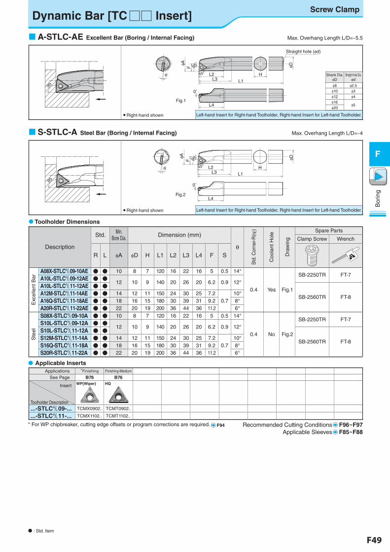
F48 F49
Bor
ing
F
N�: Std. Item
Applications *Finishing Finishing-Medium
See Page B76 B76
Insert
Toolholder Description
WP(Wiper) HQ
...-STLC&09-... TCMX0902.. TCMT0902..
...-STLC&11-... TCMX1102.. TCMT1102..
Recommended Cutting Conditions F96~F97Applicable Sleeves F85~F88
Dynamic Bar [TC□□ Insert]
Description
Std. Min. Bore Dia. Dimension (mm)
θS
td. C
orne
r-R(r
ε)
Coo
lant
Hol
e
Dra
win
g
Spare Parts
Clamp Screw Wrench
R L φA φD H L1 L2 L3 L4 F S
Exc
elle
nt B
ar
A08X-STLC&09-10AE ● ● 10 8 7 120 16 22 16 5 0.5 14°
0.4 Yes Fig.1
SB-2250TR FT-7A10L-STLC&09-12AE ● ●
12 10 9 140 20 26 20 6.2 0.9 12°A10L-STLC&11-12AE ● ●
SB-2560TR FT-8A12M-STLC&11-14AE ● ● 14 12 11 150 24 30 25 7.2
0.710°
A16Q-STLC&11-18AE ● ● 18 16 15 180 30 39 31 9.2 8°
A20R-STLC&11-22AE ● ● 22 20 19 200 36 44 36 11.2 6°
Ste
el
S08X-STLC&09-10A ● ● 10 8 7 120 16 22 16 5 0.5 14°
0.4 No Fig.2
SB-2250TR FT-7S10L-STLC&09-12A ● ●
12 10 9 140 20 26 20 6.2 0.9 12°S10L-STLC&11-12A ● ●
SB-2560TR FT-8S12M-STLC&11-14A ● ● 14 12 11 150 24 30 25 7.2
0.710°
S16Q-STLC&11-18A ● ● 18 16 15 180 30 39 31 9.2 8°S20R-STLC&11-22A ● ● 22 20 19 200 36 44 36 11.2 6°
Left-hand Insert for Right-hand Toolholder, Right-hand Insert for Left-hand Toolholder.
A-STLC-AE Excellent Bar (Boring / Internal Facing) Max. Overhang Length L/D=~5.5
● Right-hand shown
Shank Dia. φD
Straight hole Dia.φd
φ8 φ2.5φ10 φ3φ12 φ4φ16
φ5φ20
HL1
F
L2
L4
L3
S
φA φD
0˚
Straight hole (φd)
θ
95゚
Fig.1
95゚
95゚
Left-hand Insert for Right-hand Toolholder, Right-hand Insert for Left-hand Toolholder.
S-STLC-A Steel Bar (Boring / Internal Facing) Max. Overhang Length L/D=~4
● Right-hand shown
95゚
95゚
H
F
S
φA φD
L4
θL1
L2L3
0˚
95゚
Fig.2
Toolholder Dimensions
�Applicable Inserts�
Screw Clamp
* For WP chipbreaker, cutting edge offsets or program corrections are required. F94
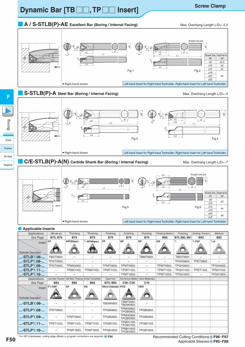
F50 F51
Bor
ing
F
Shank Dia. φD
Straight hole Dia.φd
φ8 φ2.5φ10 φ3φ12 φ4φ16
φ5φ20φ25
Shank Dia. φD
Straight hole Dia.φd
φ8φ3
φ10φ12
φ4φ16φ20
φ6φ25
Dynamic Bar [TB□□, TP□□ Insert]
95゚
95゚
Left-hand Insert for Right-hand Toolholder, Right-hand Insert for Left-hand Toolholder.
■S-STLB(P)-A Steel Bar (Boring / Internal Facing) Max. Overhang Length L/D=~4
● Right-hand shown
L1
F
L2
L4L4
L3L1
H
F
L2Hθ
θS S
φAφA φD φD
0˚5˚
Straight hole (φd)
95゚
95゚
95゚
95゚
Fig.1 Fig.2
L1
F
L2L1
H
F
Hθ
θS S
φAφA φD φD
L4 L4
L3L2
0˚ 5˚
95゚
95゚ 95
゚95゚
Fig.3 Fig.4
●�Applicable Inserts�Applications Minute ap *Finishing *Finishing Finishing Finishing Finishing Finishing-Medium Finishing Finishing / Precision Medium
See Page B75, B79 B79 B79 B79 B79 B75 B80 B75, B80, B81 B83 B82
Insert
Toolholder Description
CF WP(Wiper) &-WP(Wiper) PP GP DP HQ & &-FSF &-H
...-STLB&06-... TBGT0601.. – – – – TBMT0601.. – TBGT0601.. – –
...-STLP&08-... TPGT0802.. – – – – – – TPGH0802.. TPET0802.. –
...-STLP&09-... TPGT0902.. TPMX0902.. – TPMT0902.. TPMT0902.. – TPMT0902.. TPGH0902.. – TPGH0902..
...-STLP&11-... – TPMX1103.. TPMX1103.. TPMT1103.. TPMT1103.. – TPMT1103.. TPGH1103.. TPET1103.. TPGH1103..
...-STLP&16-... – – – – TPMT1603.. – TPMT1603.. TPGH1603.. – TPGH1603..
Applications Low Feed / Precision Soft Steel / Finishing Soft Steel / Finishing-Medium Cast Iron Non-ferrous Metals Hard Materials
See Page B83 B80 B80 B75, B84 C26~C28 C16
Insert
Toolholder Description
F&-USF XP XQ Without Chipbreaker PCD CBN
...-STLB&06-... – – – TBGW0601.. TBMT0601.. TBGW0601.. –
...-STLP&08-... TPET0802.. – – TPGB0802.. TPMH0802.. TPGB0802.. TPGB0802..
...-STLP&09-... – TPMT0902.. – TPGB0902.. TPMH0902.. TPGB0902.. TPGB0902..
...-STLP&11-... TPET1103.. TPMT1103.. TPMT1103.. TPGB1103.. TPMH1103.. TPGB1103.. TPGB1103..
...-STLP&16-... – TPMT1603.. TPMT1603.. TPGB1603.. TPMH1603.. TPGB1603.. TPGB1603..
Recommended Cutting Conditions F96~F97Applicable Sleeves F85~F88
Fig.5 Fig.6
C-STLB-A型(C06J-STLBR06-08A) F32 fig5
HL2
φDφA F
L1
L4
S
0°
θ
95゚
95゚
E-STLB-A型(E16X-STLPR11-18A) F32 fig6
HL2
φDφA F
L3
L1
L4
Straight hole (φd)
5°
S
θ95゚
95゚
Screw Clamp
95゚
95゚
Left-hand Insert for Right-hand Toolholder, Right-hand Insert for Left-hand Toolholder.
■A / S-STLB(P)-AE Excellent Bar (Boring / Internal Facing) Max. Overhang Length L/D=~5.5
● Right-hand shown
■C/E-STLB(P)-A(N) Carbide Shank Bar (Boring / Internal Facing) Max. Overhang Length L/D=~7
● Right-hand shown
* For WP chipbreaker, cutting edge offsets or program corrections are required. F94
95゚
95゚
Left-hand Insert for Right-hand Toolholder, Right-hand Insert for Left-hand Toolholder.
Solid
Positive
AD Bars
Negative
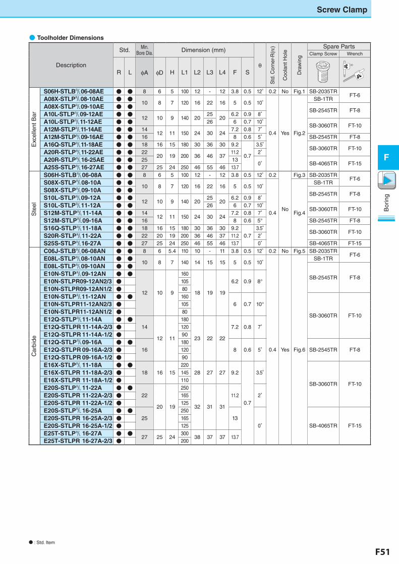
F50 F51
Bor
ing
F
Screw Clamp
N : Std. Item
●�Toolholder Dimensions
Description
Std. Min. Bore Dia. Dimension (mm)
θ
Std
. Cor
ner-R
(rε)
Coo
lant
Hol
e
Dra
win
g
Spare PartsClamp Screw Wrench
R L φA φD H L1 L2 L3 L4 F S
Exc
elle
nt B
ar
S06H-STLB&06-08AE ● ● 8 6 5 100 12 - 12 3.8 0.5 12° 0.2 No Fig.1 SB-2035TRFT-6
A08X-STLP&08-10AE ● ●10 8 7 120 16 22 16 5 0.5 10°
0.4 Yes Fig.2
SB-1TR
A08X-STLP&09-10AE ● ●SB-2545TR FT-8
A10L-STLP&09-12AE ● ●12 10 9 140 20
2520
6.2 0.9 8°A10L-STLP&11-12AE ● ● 26 6 0.7 10°
SB-3060TR FT-10A12M-STLP&11-14AE ● ● 14
12 11 150 24 30 247.2 0.8 7°
A12M-STLP&09-16AE ● ● 16 8 0.6 5° SB-2545TR FT-8
A16Q-STLP&11-18AE ● ● 18 16 15 180 30 36 30 9.2
0.7
3.5°SB-3060TR FT-10
A20R-STLP&11-22AE ● ● 2220 19 200 36 46 37
11.2 2°A20R-STLP&16-25AE ● ● 25 13
0° SB-4065TR FT-15A25S-STLP&16-27AE ● ● 27 25 24 250 46 55 46 13.7
Ste
el
S06H-STLB&06-08A ● ● 8 6 5 100 12 - 12 3.8 0.5 12° 0.2
No
Fig.3 SB-2035TRFT-6
S08X-STLP&08-10A ● ●10 8 7 120 16 22 16 5 0.5 10°
0.4 Fig.4
SB-1TR
S08X-STLP&09-10A ● ●SB-2545TR FT-8
S10L-STLP&09-12A ● ●12 10 9 140 20
2520
6.2 0.9 8°S10L-STLP&11-12A ● ● 26 6 0.7 10°
SB-3060TR FT-10S12M-STLP&11-14A ● ● 14
12 11 150 24 30 247.2 0.8 7°
S12M-STLP&09-16A ● ● 16 8 0.6 5° SB-2545TR FT-8
S16Q-STLP&11-18A ● ● 18 16 15 180 30 36 30 9.20.7
3.5°SB-3060TR FT-10
S20R-STLP&11-22A ● ● 22 20 19 200 36 46 37 11.2 2°S25S-STLP&16-27A ● ● 27 25 24 250 46 55 46 13.7 0° SB-4065TR FT-15
Car
bide
C06J-STLB&06-08AN ● ● 8 6 5.4 110 10 - 11 3.8 0.5 12° 0.2 No Fig.5 SB-2035TRFT-6
E08L-STLP&08-10AN ● ●10 8 7 140 14 15 15 5 0.5 10°
0.4 Yes Fig.6
SB-1TR
E08L-STLP&09-10AN ● ●
SB-2545TR FT-8E10N-STLP&09-12AN ● ●
12 10 9
160
18 19 19
6.2 0.9 8°E10N-STLPR09-12AN2/3 ● 105
E10N-STLPR09-12AN1/2 ● 80
E10N-STLP&11-12AN ● ● 1606 0.7 10°
SB-3060TR FT-10
E10N-STLPR11-12AN2/3 ● 105
E10N-STLPR11-12AN1/2 ● 80
E12Q-STLP&�11-14A ● ●14
12 11
180
23 22 22
7.2 0.8 7°E12Q-STLPR�11-14A-2/3 ● 120
E12Q-STLPR�11-14A-1/2 ● 90
E12Q-STLP&�09-16A ● ●16
1808 0.6 5° SB-2545TR FT-8E12Q-STLPR�09-16A-2/3 ● 120
E12Q-STLPR�09-16A-1/2 ● 90
E16X-STLP&�11-18A ● ●18 16 15
22028 27 27 9.2
0.7
3.5°
SB-3060TR FT-10
E16X-STLPR�11-18A-2/3 ● 145
E16X-STLPR�11-18A-1/2 ● 110
E20S-STLP&�11-22A ● ●22
20 19
250
32 31 31
11.2 2°E20S-STLPR�11-22A-2/3 ● 165
E20S-STLPR�11-22A-1/2 ● 125
E20S-STLP&�16-25A ● ●25
25013
0° SB-4065TR FT-15E20S-STLPR�16-25A-2/3 ● 165
E20S-STLPR�16-25A-1/2 ● 125
E25T-STLP&�16-27A ● ●27 25 24
30038 37 37 13.7
E25T-STLPR�16-27A-2/3 ● 200
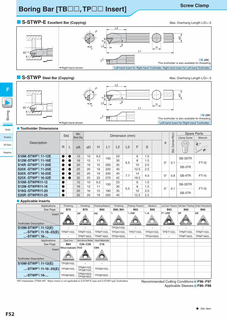
F52 F53
Bor
ing
F
L3 S0°
0°
φA
This toolholder is also available for threading.
L2
F
L1H
φ D
Left-hand Insert for Right-hand Toolholder.
N : Std. Item
60°
S-STWP Steel Bar (Copying) Max. Overhang Length L/D=~3
● Right-hand shown
L3 S
0°
0°
φAL2
F
L1H
This toolholder is also available for threading.
φ D
Left-hand Insert for Right-hand Toolholder, Right-hand Insert for Left-hand Toolholder.
60°
S-STWP-E Excellent Bar (Copying) Max. Overhang Length L/D=~5
● Right-hand shown
Toolholder Dimensions
Applicable Inserts Applications Finishing Finishing Finishing-Medium Finishing Finishing / Precision Medium Low Feed / Precision Soft Steel / Finishing Soft Steel / Finishing-Medium
See Page B79 B79 B80 B80, B81 B83 B82 B83 B80 B80
Insert
Toolholder Description
PP GP HQ & &-FSF &-H F&-USF XP XQ
S10M-STWP&11-12(E) - - - TPGH1102.. - - - - - ...-STWP&11-16~25(E) TPMT1103.. TPMT1103.. TPMT1103.. TPGH1103.. TPET1103.. TPGH1103.. TPET1103.. TPMT1103.. TPMT1103.. ...-STWP&16-... - TPMT1603.. TPMT1603.. TPGH1603.. - TPGH1603.. - TPMT1603.. TPMT1603..
Applications Cast Iron Non-ferrous Metals Hard Materials
See Page B84 C26~C28 C16
Insert
Toolholder Description
Without chipbreaker PCD CBN
S10M-STWP&11-12(E) TPGB1102.. - - ...-STWP&11-16~25(E) TPGB1103.. TPMH1103..
TPGB1103.. TPGB1103..
...-STWP&16-... TPGB1603.. TPMH1603.. TPGB1603.. TPGB1603..
*WP chipbreaker (TPMX-WP : Wiper insert) is not applicable to S-STWP-E type and S-STWP type Toolholders. Recommended Cutting Conditions F96~F97Applicable Sleeves F86~F88
Description
Std. Min. Bore Dia. Dimension (mm)
θ
Std
. Cor
ner-R
(rε) Spare Parts
Clamp Screw Wrench
R L φA φD H L1 L2 L3 F S
S10M-STWP&11-12E ● ● 12 10 9.2150
23
5.5
6 1.0
0° 0.1SB-3STR
FT-10S12M-STWP&11-16E ● ● 16 12 11 30 8 1.5
S16R -STWP&11-20E ● ● 20 16 15 200 35 10 2.0SB-3TR
S20X -STWP&11-25E ● ● 25 20 19 220 40 12.5 2.5
S20X -STWP&16-25E ● ● 25 20 19 220 407.7
144.0 0° 0.8 SB-4TR FT-15
S25X -STWP&16-32E ● ● 32 25 23 270 42 16.5
S10M-STWPR11-12 ● 12 10 9.2150
23
5.5
6 1.0
0° 0.1SB-3STR
FT-10S12M-STWPR11-16 ● 16 12 11 30 8 1.5
S16Q -STWPR11-20 ● 20 16 15 180 35 10 2.0SB-3TR
S20R -STWPR11-25 ● 25 20 19 200 40 12.5 2.5
( J35)
( J35)
Boring Bar [TB, TP Insert]Screw Clamp
Solid
Positive
AD Bars
Negative
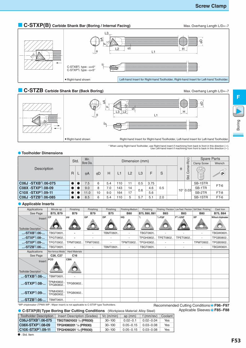
F52 F53
Bor
ing
F
Applications Minute ap Finishing Finishing Finishing Finishing-Medium Finishing Finishing / Precision Low Feed / Precision Soft Steel / Finishing Cast Iron
See Page B75, B79 B79 B79 B75 B80 B75, B80, B81 B83 B83 B80 B75, B84
Insert
Toolholder Description
CF PP GP DP HQ & &-FSF F&-USF XP Without chipbreaker
...-STXB&06-... TBGT0601.. - - TBMT0601.. - TBGT0601.. - - - TBGW0601..
...-STXP&08-... TPGT0802.. - - - - TPGH0802.. TPET0802.. TPET0802.. - TPGB0802..
...-STXP&09-... TPGT0902.. TPMT0902.. TPMT0902.. - TPMT0902.. TPGH0902.. - - TPMT0902.. TPGB0902..
...-STZB&06-... TBGT0601.. - - TBMT0601.. - TBGT0601.. - - - TBGW0601..
Applications Non-ferrous Metals Hard Materials
See Page C26, C27 C16
Insert
Toolholder Description
PCD CBN
...-STXB&06-... TBMT0601.. -
...-STXP&08-... TPMH0802..TPGB0802.. TPGB0802..
...-STXP&09-... TPMH0902..TPGB0902.. TPGB0902..
...-STZB&06-... TBMT0601.. -
Recommended Cutting Conditions F96~F97Applicable Sleeves F85~F88
Description
Std. Min. Bore Dia. Dimension (mm)
θ
Std
. Cor
ner-R
(rε) Spare Parts
Clamp Screw Wrench
R L φA φD H L1 L2 L3 F S
C06J -STXB&06-075 ● ● 7.5 6 5.4 110 11 0.5 3.750.5
10° 0.03
SB-1STRFT-6
C08X -STXP&08-09 ● ● 9.0 8 7.0 143 140.6
4.6 SB-1TR
C10X -STXP&09-11 ● ● 11.0 10 9.0 164 17 5.6 SB-2TR FT-8C06J -STZB&06-085 ● ● 8.5 6 5.4 110 5 5.7 5.1 2.0 SB-1STR FT-6
N : Std. Item
C-STXP(B) Carbide Shank Bar (Boring / Internal Facing) Max. Overhang Length L/D=~7
C-STZB Carbide Shank Bar (Back Boring) Max. Overhang Length L/D=~7
Applicable Inserts
* When using Right-hand Toolholder, use Right-hand insert if machining from back to front in this direction ().Use Left-hand insert if machining from front to back in this direction (!).
Toolholder Dimensions
C-STXP(B) Type Boring Bar Cutting Conditions (Workpiece Material: Alloy Steel)
Toolholder Description Insert Description (Grades) Vc (m/min) ap (mm) f (mm/rev) CoolantC06J-STXB&06-075 TBGT0601003 L/R (PR930) 30~100 0.02~0.1 0.02~0.04 Yes
C08X-STXP&08-09 TPGH080201 L/R (PR930) 30~100 0.05~0.15 0.03~0.08 YesC10X -STXP&09-11 TPGH090201 L/R (PR930) 30~100 0.05~0.15 0.03~0.08 Yes
Screw Clamp
110゚
110゚
φD
HL2L1
L3
FφA
θ
α
S
110゚110゚
● Right-hand shown Left-hand Insert for Right-hand Toolholder, Right-hand Insert for Left-hand Toolholder.
( )
95゚95゚
φD
L3 L2L1
FφA
S
θ
0°
H
95゚95゚
● Right-hand shown Right-hand Insert for Right-hand Toolholder, Left-hand Insert for Left-hand Toolholder.
C-STXB& type···α=0°C-STXP& type···α=5°
*WP chipbreaker (TPMX-WP : Wiper insert) is not applicable to C-STXP type Toolholders.
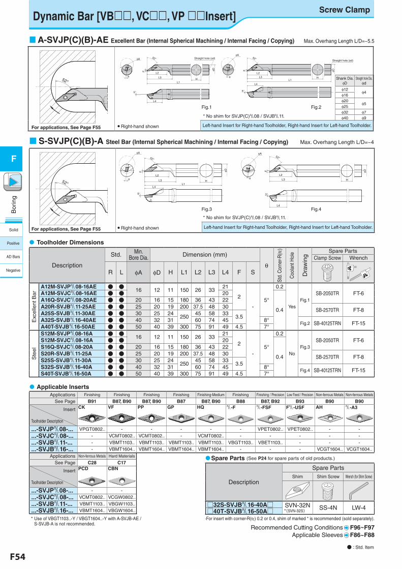
F54 F55
Bor
ing
F
Bor
ing
F
Shank Dia.φD
Straight hole Dia.φd
φ12φ4
φ16 φ20
φ5φ25 φ32 φ7φ40 φ9
Dynamic Bar [VB, VC, VP Insert]
Left-hand Insert for Right-hand Toolholder, Right-hand Insert for Left-hand Toolholder.
S-SVJP(C)(B)-A Steel Bar (Internal Spherical Machining / Internal Facing / Copying) Max. Overhang Length L/D=~4
● Right-hand shown
A-SVJP(C)(B)-AE Excellent Bar (Internal Spherical Machining / Internal Facing / Copying) Max. Overhang Length L/D=~5.5
● Right-hand shown
Fig.1 Fig.2
Fig.3 Fig.4
S-SVJB-A型(S32S-SVJBL16-40A) F36 fig4
φD
HL3
F
52°φA
3°
L4
θL2
* No shim for SVJP(C)&08 / SVJB&11.
* No shim for SVJP(C)&08 / SVJB&11.
S-SVJB-A型 F36
52°
52°
A-SVJB-AE型(A20R-SVJBRL11-25AE) F36 fig1
φD
HL3
L2
F
L1
φA 52° Straight hole (φd)
L4
5°
θ
S20R-SVJB-A型(S20R-SVJBL11-25A) F36 fig3
φD
H
L2
L3L1
52°
φA
L4
5°
F
θ
A-SVJB-AE型(A32S-SVJBRL16-40AE) F36 fig2
φD
HL3
F
52°
L1
L4
5°
φA
L2θ
Straight hole (φd)
Screw Clamp
For applications, See Page F55
For applications, See Page F55
Description
Std. Min. Bore Dia. Dimension (mm)
θ
Std.
Cor
ner-R
(rε)
Coo
lant
Hol
e
Dra
win
g
Spare PartsClamp Screw Wrench
R L φA φD H L1 L2 L3 L4 F S
Exc
elle
nt B
ar
A12M-SVJP&08-16AE ● ● 16 12 11 150 26 3321
2
-5°
0.2
YesFig.1
SB-2050TR FT-6A12M-SVJC&08-16AE ● ● 20
0.4
A16Q-SVJC&08-20AE ● ● 20 16 15 180 36 43 22A20R-SVJB&11-25AE ● ● 25 20 19 200 37.5 48 30
SB-2570TR FT-8A25S-SVJB&11-30AE ● ● 30 25 24
25045 58 33
3.5A32S-SVJB&16-40AE ● ● 40 32 31 60 74 45 8°
Fig.2 SB-40125TRN FT-15A40T-SVJB&16-50AE ● ● 50 40 39 300 75 91 49 4.5 7°
Ste
el
S12M-SVJP&08-16A ● ● 16 12 11 150 26 3321
2
-5°
0.2
NoFig.3
SB-2050TR FT-6S12M-SVJC&08-16A ● ● 20
0.4
S16Q-SVJC&08-20A ● ● 20 16 15 180 36 43 22S20R-SVJB&11-25A ● ● 25 20 19 200 37.5 48 30
SB-2570TR FT-8S25S-SVJB&11-30A ● ● 30 25 24
25045 58 33
3.5S32S-SVJB&16-40A ● ● 40 32 31 60 74 45 8°
Fig.4 SB-40125TRN FT-15S40T-SVJB&16-50A ● ● 50 40 39 300 75 91 49 4.5 7°
Toolholder Dimensions
Applications Finishing Finishing Finishing Finishing Finishing-Medium Finishing Finishing / Precision Low Feed / Precision Non-ferrous Metals Non-ferrous Metals
See Page B91 B87, B90 B87, B90 B87 B87, B90 B88 B87, B92 B93 B90 B90
Insert
Toolholder Description
CK VF PP GP HQ &-F &-FSF F&-USF AH &-A3
...-SVJP&08-... VPGT0802.. - - - - - VPET0802.. VPET0802.. - -
...-SVJC&08-... - VCMT0802.. VCMT0802.. - VCMT0802.. - - - - -
...-SVJB&11-... - VBMT1103.. VBMT1103.. VBMT1103.. VBMT1103.. VBGT1103.. VBET1103.. - - -
...-SVJB&16-... - VBMT1604.. VBMT1604.. VBMT1604.. VBMT1604.. - - - VCGT1604.. VCGT1604..
Applications Non-ferrous Metals Hard Materials
See Page C28 C17
Insert
Toolholder Description
PCD CBN
...-SVJP&08-... - -
...-SVJC&08-... VCMT0802.. VCGW0802..
...-SVJB&11-... VBMT1103.. VBGW1103..
...-SVJB&16-... VBMT1604.. VBGW1604..
·For insert with corner-R(re) 0.2 or 0.4, shim of marked * is recommended (sold separately).
Recommended Cutting Conditions F96~F97 Applicable Sleeves F86~F88
Applicable Inserts
● : Std. Item
Description
Spare PartsShim Shim Screw Wrench (for Shim Screw)
□32S-SVJB&16-40A□ SVN-32N*(SVN-32S) SS-4N LW-4□40T-SVJB&16-50A□
Spare Parts (See P24 for spare parts of old products.)
Left-hand Insert for Right-hand Toolholder, Right-hand Insert for Left-hand Toolholder.
Solid
Positive
AD Bars
Negative
* Use of VBGT1103..-Y / VBGT1604..-Y with A-SVJB-AE / S-SVJB-A is not recommended.
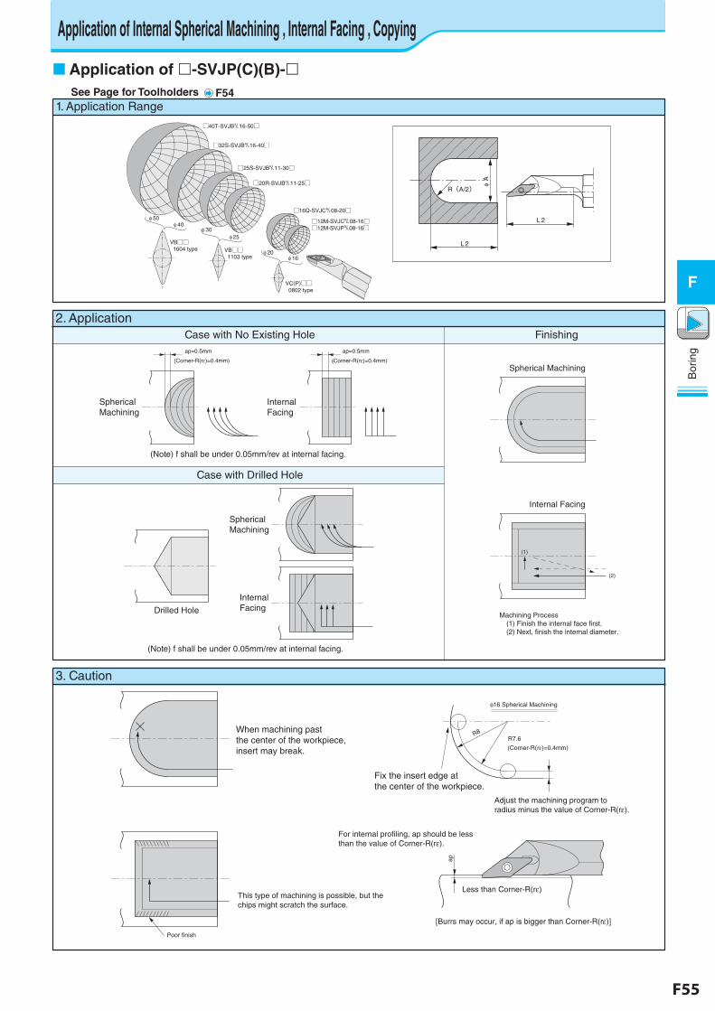
F54 F55
Bor
ing
F
Bor
ing
F
Application of -SVJP(C)(B)-See Page for Toolholders F54
2. ApplicationCase with No Existing Hole Finishing
Case with Drilled Hole
1. Application Range
□40T-SVJB&16-50□
VB□□ 1604 type VB□□
1103 type
VC(P)□□ 0802 type
□32S-SVJB&16-40□
□25S-SVJB&11-30□
□20R-SVJB&11-25□
□16Q-SVJC&08-20□
□12M-SVJC&08-16□□12M-SVJP&08-16□
φ 50φ 40
φ 30φ 25
φ 20φ 16
L 2
L 2
φ A
R(A/2)
ap=0.5mm
(Corner-R(rε)=0.4mm)
ap=0.5mm
(Corner-R(rε)=0.4mm)
Internal Facing
(rε)
Spherical Machining
Spherical Machining
Internal Facing
Machining Process (1) Finish the internal face first. (2) Next, finish the internal diameter.
(1)
(2)
Spherical Machining
Drilled Hole
Internal Facing
3. Caution
When machining pastthe center of the workpiece,insert may break.
Poor finish
This type of machining is possible, but thechips might scratch the surface.
φ16 Spherical Machining
R8
Fix the insert edge at the center of the workpiece.
Adjust the machining program toradius minus the value of Corner-R(rε).
ap
Less than Corner-R(rε)
[Burrs may occur, if ap is bigger than Corner-R(rε)]
For internal profiling, ap should be lessthan the value of Corner-R(rε).
R7.6
(Corner-R(rε)=0.4mm)
(Note) f shall be under 0.05mm/rev at internal facing.
(Note) f shall be under 0.05mm/rev at internal facing.
Application of Internal Spherical Machining , Internal Facing , Copying
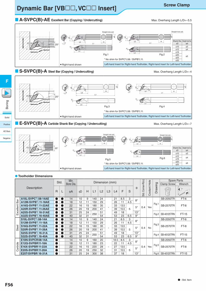
F56 F57
Bor
ing
F
Bor
ing
F
Screw Clamp
Description
Std. Min. Bore Dia. Dimension (mm)
θ
Std.
Cor
ner-R
(rε)
Coo
lant
Hol
e
Dra
win
g
Spare PartsClamp Screw Wrench
R L φA φD H L1 L2 L3 L4 F S
Exc
elle
nt B
ar
A10L-SVPC&08-14AE ● ● 14 10 9 140 24
-
21 8.5 38°
0.4 YesFig.1
SB-2050TR FT-6A12M-SVPB&11-18AE ● ● 18 12 11 150 29 26 11 4.5
SB-2570TR FT-8A16Q-SVPB&11-22AE ● ● 22 16 15 180 35 33 13.55
5°A20R-SVPB&11-26AE ● ● 26 20 19 200 41 39 15.5A25S-SVPB&16-31AE ● ● 31 25 24
25051 49 18 13°
Fig.2 SB-40125TRN FT-15A32S-SVPB&16-40AE ● ● 40 32 31 54 53 23 6.5 9°
Ste
el
S10L-SVPC&08-14A ● ● 14 10 9 140 24
-
21 8.5 38°
0.4 NoFig.3
SB-2050TR FT-6S12M-SVPB&11-18A ● ● 18 12 11 150 29 26 11 4.5
SB-2570TR FT-8S16Q-SVPB&11-22A ● ● 22 16 15 180 35 33 13.55
5°S20R-SVPB&11-26A ● ● 26 20 19 200 41 39 15.5S25S-SVPB&16-31A ● ● 31 25 24
25051 49 18 13°
Fig.4 SB-40125TRN FT-15S32S-SVPB&16-40A ● ● 40 32 31 54 53 23 6.5 9°
Car
bide
E10N-SVPCR 08-14A ● 14 10 9 160 20
-
18.5 8.5 38°
0.4 YesFig.5
SB-2050TR FT-6E12Q-SVPBR 11-18A ● 18 12 11 180 23 22 11 4.5
SB-2570TR FT-8E16X-SVPBR 11-22A ● 22 16 15 220 28 27 13.55
5°E20S-SVPBR 11-26A ● 26 20 19 250 32 31 15.5E25T-SVPBR 16-31A ● 31 25 24 300 38 37 18 13° Fig.6 SB-40125TRN FT-15
Toolholder Dimensions
Shank Dia.φD
Straight hole Dia.φd
φ10 φ3φ12
φ4φ16 φ20
φ6φ25
Shank Dia.φD
Straight hole Dia.φd
φ10 φ3φ12 φ4φ16
φ5φ20φ25φ32
Dynamic Bar [VB, VC Insert]
Left-hand Insert for Right-hand Toolholder, Right-hand Insert for Left-hand Toolholder.
Left-hand Insert for Right-hand Toolholder, Right-hand Insert for Left-hand Toolholder.
S-SVPC(B)-A Steel Bar (Copying / Undercutting) Max. Overhang Length L/D=~4
● Right-hand shown
A-SVPC(B)-AE Excellent Bar (Copying / Undercutting) Max. Overhang Length L/D=~5.5
● Right-hand shown
Left-hand Insert for Right-hand Toolholder, Right-hand Insert for Left-hand Toolholder.
E-SVPC(B)-A Carbide Shank Bar (Copying / Undercutting) Max. Overhang Length L/D=~7
Fig.1 Fig.2
Fig.3 Fig.4
Fig.6
S-SVPC-A型(S10L-SVPCR08-14A) F36 fig7
φD
H
S
L2L1
FφA
θ
L4
5°
117.5°
S-SVPB-A型(S25S-SVPBR16-31A) F36 fig8
φD
H
S
L2
FφA
θ
L4
5°
L1
117.5°
E-SVPB-A型(E16X-SVPBR11-22A) F36 fig9
φD
H
S
L2L1
FφA
L4
5°
Straight hole (φd)
θ
● Right-hand shown
* No shim for SVPC&08 / SVPB&11.
* No shim for SVPC&08 / SVPB&11.
* No shim for SVPC&08 / SVPB&11.
E-SVPB-A型 F36
25°117.5°117.5°
A-SVPC-AE型 F36
117.5° 25°117.5°117.5°
E-SVPB-A型(E25T-SVPBR16-31A) F36 fig10
φD
H
S
L1
F
L2
L4
φA
5°
Straight hole (φd)
θ
S-SVPC-A型 F36
117.5°117.5° 25°
A-SVPC-AE型(A10L-SVPCR08-14AE)F36 fig5
H
φD
Straight hole (φd)
L2
S
φA F
L1
L4
5°
θ
117.5°
A-SVPB-AE型(A25S-SVPBR16-31AE) F36 fig6
H
φD
Straight hole (φd)
L2
F
S
L1
L4
5°
φA
θ
● : Std. Item
Fig.5
Solid
Positive
AD Bars
Negative
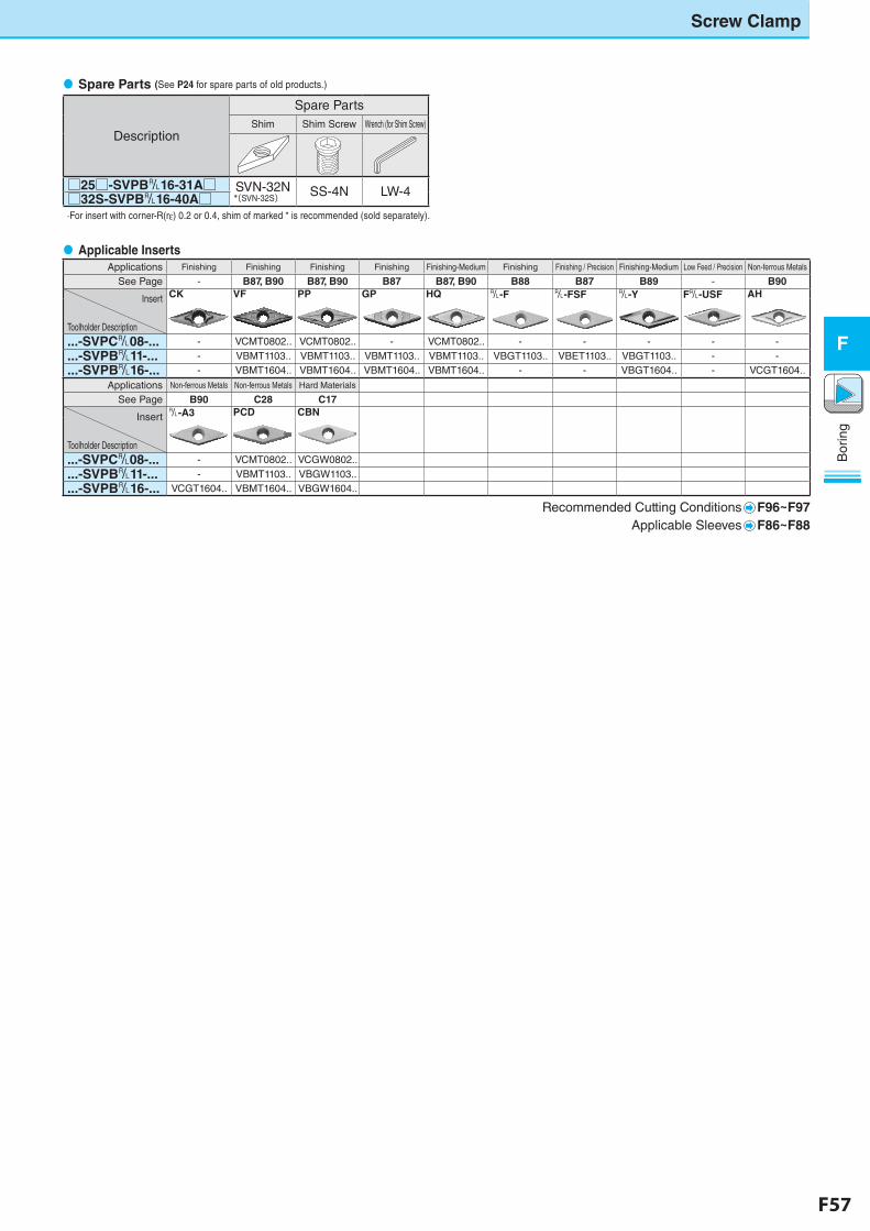
F56 F57
Bor
ing
F
Bor
ing
F
Screw Clamp
Description
Spare PartsShim Shim Screw Wrench (for Shim Screw)
□25□-SVPB&16-31A□ SVN-32N*(SVN-32S) SS-4N LW-4□32S-SVPB&16-40A□
Spare Parts (See P24 for spare parts of old products.)
Applications Finishing Finishing Finishing Finishing Finishing-Medium Finishing Finishing / Precision Finishing-Medium Low Feed / Precision Non-ferrous Metals
See Page - B87, B90 B87, B90 B87 B87, B90 B88 B87 B89 - B90
Insert
Toolholder Description
CK VF PP GP HQ &-F &-FSF &-Y F&-USF AH
...-SVPC&08-... - VCMT0802.. VCMT0802.. - VCMT0802.. - - - - -
...-SVPB&11-... - VBMT1103.. VBMT1103.. VBMT1103.. VBMT1103.. VBGT1103.. VBET1103.. VBGT1103.. - -
...-SVPB&16-... - VBMT1604.. VBMT1604.. VBMT1604.. VBMT1604.. - - VBGT1604.. - VCGT1604..
Applications Non-ferrous Metals Non-ferrous Metals Hard Materials
See Page B90 C28 C17
Insert
Toolholder Description
&-A3 PCD CBN
...-SVPC&08-... - VCMT0802.. VCGW0802..
...-SVPB&11-... - VBMT1103.. VBGW1103..
...-SVPB&16-... VCGT1604.. VBMT1604.. VBGW1604..
Recommended Cutting Conditions F96~F97Applicable Sleeves F86~F88
Applicable Inserts
·For insert with corner-R(re) 0.2 or 0.4, shim of marked * is recommended (sold separately).
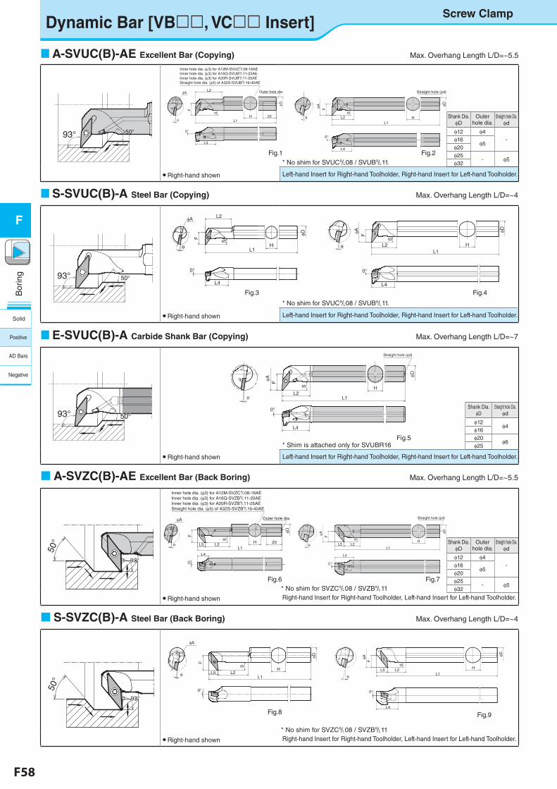
F58 F59
Bor
ing
F
Bor
ing
F
Left-hand Insert for Right-hand Toolholder, Right-hand Insert for Left-hand Toolholder.
Shank Dia.φD
Straight hole Dia.φd
φ12 φ4
φ16φ20
φ6φ25
Shank Dia.φD
Outer hole dia.
Straight hole Dia.φd
φ12 φ4-φ16
φ5φ20φ25
- φ5φ32
Shank Dia.φD
Outer hole dia.
Straight hole Dia.φd
φ12 φ4-φ16
φ5φ20φ25
- φ5φ32
Dynamic Bar [VB, VC Insert]
Left-hand Insert for Right-hand Toolholder, Right-hand Insert for Left-hand Toolholder.
S-SVUC(B)-A Steel Bar (Copying) Max. Overhang Length L/D=~4
● Right-hand shown
Right-hand Insert for Right-hand Toolholder, Left-hand Insert for Left-hand Toolholder.
A-SVZC(B)-AE Excellent Bar (Back Boring) Max. Overhang Length L/D=~5.5
● Right-hand shown
A-SVUC(B)-AE Excellent Bar (Copying) Max. Overhang Length L/D=~5.5
● Right-hand shown
Left-hand Insert for Right-hand Toolholder, Right-hand Insert for Left-hand Toolholder.
E-SVUC(B)-A Carbide Shank Bar (Copying) Max. Overhang Length L/D=~7
Right-hand Insert for Right-hand Toolholder, Left-hand Insert for Left-hand Toolholder.
S-SVZC(B)-A Steel Bar (Back Boring) Max. Overhang Length L/D=~4
● Right-hand shown
A-SVUB-AE型(A20R-SVUBR11-25AE) F38 fig1
H
φD
Outer hole dia.
L1
F
L4
θ
S
L2
20
φA
0°
Inner hole dia. (φ3) for A12M-SVUC&08-16AEInner hole dia. (φ3) for A16Q-SVUB&11-20AEInner hole dia. (φ3) for A20R-SVUB&11-25AEStraight hole dia. (φ5) of A32S-SVUB&16-40AE
A-SVUB-AE型(A25S-SVUBR16-34AE) F38 fig2
H
φD
L2
S
FφA
L1
Straight hole (φd)
θ
L4
0°
S-SVUC-A型(S12M-SVUCR08-16A) F38 fig3
φD
L2
HL1θ
L4
SφA
F
0°
S-SVUB-A型(S25S-SVUBR16-34A) F38 fig4
H
φD
L2
S
FφA
θ
L4
L1
0°
E-SVUB-A型(E16X-SVUBR11-25A) F38 fig5
φD
HS
L1
F
L2θ
φA
Straight hole (φd)
L4
0°
0°
A-SVZB-AE(A16Q-SVZBRL11-20AE) F38 fig6
φD
F
H
S
L2L5 20L1
L4
θ
φA Outer hole dia.
Inner hole dia. (φ3) for A12M-SVZC&08-16AEInner hole dia. (φ3) for A16Q-SVZB&11-20AEInner hole dia. (φ3) for A20R-SVZB&11-25AEStraight hole dia. (φ5) of A32S-SVZB&16-40AE
A-SVZB-AE型(A25S-SVZBRL16-34AE) F38 fig7
φD
HS
L2L5L1
FφA
Straight hole (φd)
L4
θ
0°
S-SVZB-A型(S16Q-SVZBRL11-20A) F38 fig8
H
S
L2L1
F
θ
φA
φD
L5
0°
S-SVZC-A型(S25S-SVZBRL16-34A) F38 fig9
φD
H
S
L2L5L1
FφA
L4
0°
θ
* No shim for SVZC&08 / SVZB&11
● Right-hand shown
* No shim for SVZC&08 / SVZB&11
A-SVUB-AE型 F38
50°93°
S-SVUC-A型 F38
50°50°93°
E-SVUB-A型 F38
50°50°93°
A-SVZB-AE F38
50°
93°93°
S-SVZB-A F38
50°
93°93°
Screw Clamp
* No shim for SVUC&08 / SVUB&11.
* No shim for SVUC&08 / SVUB&11.
* Shim is attached only for SVUBR16
Fig.1
Fig.5
Fig.4 Fig.3
Fig.6
Fig.8 Fig.9
Fig.7
Fig.2
Solid
Positive
AD Bars
Negative
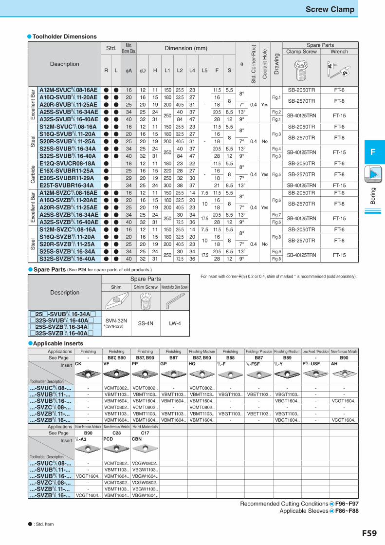
F58 F59
Bor
ing
F
Bor
ing
F
Screw Clamp
● : Std. Item
Description
Spare PartsShim Shim Screw Wrench (for Shim Screw)
□25□-SVUB&16-34A□SVN-32N
*(SVN-32S)SS-4N LW-4□32S-SVUB&16-40A□
□25S-SVZB&16-34A□□32S-SVZB&16-40A□
Toolholder Dimensions
Spare Parts (See P24 for spare parts of old products.)
Applicable Inserts
Description
Std. Min. Bore Dia. Dimension (mm)
θ
Std
. Cor
ner-
R(rε)
Coo
lant
Hol
e
Dra
win
g
Spare PartsClamp Screw Wrench
R L φA φD H L1 L2 L4 L5 F S
Exc
elle
nt B
ar A12M-SVUC&08-16AE ● ● 16 12 11 150 25.5 23
-
11.5 5.58°
0.4 Yes
Fig.1
SB-2050TR FT-6
A16Q-SVUB&11-20AE ● ● 20 16 15 180 32.5 27 168 SB-2570TR FT-8
A20R-SVUB&11-25AE ● ● 25 20 19 200 40.5 31 18 7°
A25S-SVUB&16-34AE ● ● 34 25 24250
40 37 20.5 8.5 13° Fig.2SB-40125TRN FT-15
A32S-SVUB&16-40AE ● ● 40 32 31 84 47 28 12 9° Fig.1
Ste
el
S12M-SVUC&08-16A ● ● 16 12 11 150 25.5 23
-
11.5 5.58°
0.4 No
Fig.3
SB-2050TR FT-6
S16Q-SVUB&11-20A ● ● 20 16 15 180 32.5 27 168 SB-2570TR FT-8
S20R-SVUB&11-25A ● ● 25 20 19 200 40.5 31 18 7°
S25S-SVUB&16-34A ● ● 34 25 24250
40 37 20.5 8.5 13° Fig.4SB-40125TRN FT-15
S32S-SVUB&16-40A ● ● 40 32 31 84 47 28 12 9° Fig.3
Car
bide
E12Q-SVUCR08-18A ● 18 12 11 180 23 22
-
11.5 5.58°
0.4 Yes Fig.5
SB-2050TR FT-6
E16X-SVUBR11-25A ● 25 16 15 220 28 27 168 SB-2570TR FT-8
E20S-SVUBR11-29A ● 29 20 19 250 32 30 18 7°
E25T-SVUBR16-34A ● 34 25 24 300 38 37 21 8.5 13° SB-40125TRN FT-15
Exc
elle
nt B
ar A12M-SVZC&08-16AE ● ● 16 12 11 150 25.5 14 7.5 11.5 5.58°
0.4 Yes
Fig.6
SB-2050TR FT-6
A16Q-SVZB&11-20AE ● ● 20 16 15 180 32.5 2010
168 SB-2570TR FT-8
A20R-SVZB&11-25AE ● ● 25 20 19 200 40.5 23 18 7°
A25S-SVZB&16-34AE ● ● 34 25 24250
30 3417.5
20.5 8.5 13° Fig.7SB-40125TRN FT-15
A32S-SVZB&16-40AE ● ● 40 32 31 72.5 36 28 12 9° Fig.6
Ste
el
S12M-SVZC&08-16A ● ● 16 12 11 150 25.5 14 7.5 11.5 5.58°
0.4 No
Fig.8
SB-2050TR FT-6
S16Q-SVZB&11-20A ● ● 20 16 15 180 32.5 2010
168 SB-2570TR FT-8
S20R-SVZB&11-25A ● ● 25 20 19 200 40.5 23 18 7°
S25S-SVZB&16-34A ● ● 34 25 24250
30 3417.5
20.5 8.5 13° Fig.9SB-40125TRN FT-15
S32S-SVZB&16-40A ● ● 40 32 31 72.5 36 28 12 9° Fig.8
Applications Finishing Finishing Finishing Finishing Finishing-Medium Finishing Finishing / Precision Finishing-Medium Low Feed / Precision Non-ferrous Metals
See Page - B87, B90 B87, B90 B87 B87, B90 B88 B87 B89 - B90
Insert
Toolholder Description
CK VF PP GP HQ &-F &-FSF &-Y F&-USF AH
...-SVUC&08-... - VCMT0802.. VCMT0802.. - VCMT0802.. - - - - -
...-SVUB&11-... - VBMT1103.. VBMT1103.. VBMT1103.. VBMT1103.. VBGT1103.. VBET1103.. VBGT1103.. - -
...-SVUB&16-... - VBMT1604.. VBMT1604.. VBMT1604.. VBMT1604.. - - VBGT1604.. - VCGT1604..
...-SVZC&08-... - VCMT0802.. VCMT0802.. - VCMT0802.. - - - - -
...-SVZB&11-... - VBMT1103.. VBMT1103.. VBMT1103.. VBMT1103.. VBGT1103.. VBET1103.. VBGT1103.. - -
...-SVZB&16-... - VBMT1604.. VBMT1604.. VBMT1604.. VBMT1604.. - - VBGT1604.. - VCGT1604..
Applications Non-ferrous Metals Non-ferrous Metals Hard Materials
See Page B90 C28 C17
Insert
Toolholder Description
&-A3 PCD CBN
...-SVUC&08-... - VCMT0802.. VCGW0802..
...-SVUB&11-... - VBMT1103.. VBGW1103..
...-SVUB&16-... VCGT1604.. VBMT1604.. VBGW1604..
...-SVZC&08-... - VCMT0802.. VCGW0802..
...-SVZB&11-... - VBMT1103.. VBGW1103..
...-SVZB&16-... VCGT1604.. VBMT1604.. VBGW1604..
Recommended Cutting Conditions F96~F97Applicable Sleeves F86~F88
·For insert with corner-R(re) 0.2 or 0.4, shim of marked * is recommended (sold separately).
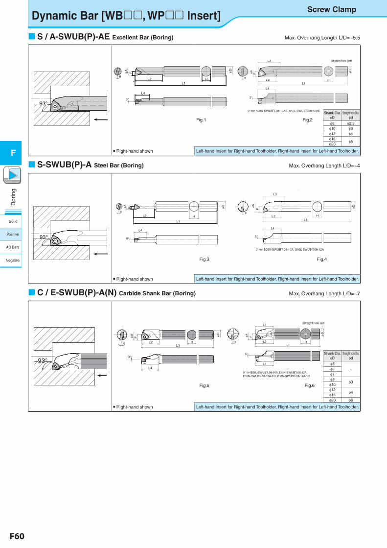
F60 F61
Bor
ing
F
Bor
ing
FLeft-hand Insert for Right-hand Toolholder, Right-hand Insert for Left-hand Toolholder.
S-SWUB-AE型(S10H-SWUBR08-08AE)
F
F40 fig1
θ
φA
HL2
φD
L4
L1
0°
Shank Dia.φD
Straight hole Dia.φd
φ8 φ2.5φ10 φ3φ12 φ4φ16
φ5φ20
Shank Dia.φD
Straight hole Dia.φd
φ5-φ6
φ7φ8
φ3φ10φ12
φ4φ16 φ20 φ6
Dynamic Bar [WB, WP Insert]
S / A-SWUB(P)-AE Excellent Bar (Boring) Max. Overhang Length L/D=~5.5
● Right-hand shown
Left-hand Insert for Right-hand Toolholder, Right-hand Insert for Left-hand Toolholder.
S-SWUB(P)-A Steel Bar (Boring) Max. Overhang Length L/D=~4
● Right-hand shown
Left-hand Insert for Right-hand Toolholder, Right-hand Insert for Left-hand Toolholder.
C / E-SWUB(P)-A(N) Carbide Shank Bar (Boring) Max. Overhang Length L/D=~7
● Right-hand shown
Fig.1 Fig.2
Fig.3
A-SWUP-AE型(A16Q-SWUPR16-18AE)
L 2
F40 fig2
θ
φA F
H
L3
L4
L1
φD
Straight hole (φd)
5°
0° for A08X-SWUB&08-10AE, A10L-SWUB&08-12AE
C-SWUB-A型(C06J-SWUBR06-07A)F40 fig5
φD
HL2
FφA
L1θ
L4
0°
93°93°
93°93°
93°93°
E-SWUP-A型(E16X-SWUPR11-18A) F40 fig6
φD
HL2
FφA
L1
L3
L4
θ
Straight hole (φd)
5°
0° for E08L-SWUB&08-10A,E10N-SWUB&08-12A,E10N-SWUB&08-12A-2/3, E10N-SWUB&08-12A-1/2
S-SWUB-A型(S10H-SWUBR06-06A)
L2
F
F40 fig3
θH
φA φDL1
L4
0°
S-SWUP-A型(S16Q-SWUPR11-18A)
L2
F
F40 fig4
θ
φA
L3
H
φD
L4
5°
0° for S08X-SWUB&08-10A, S10L-SWUB&08-12A
L1
Fig.4
Screw Clamp
Fig.5 Fig.6
Solid
Positive
AD Bars
Negative
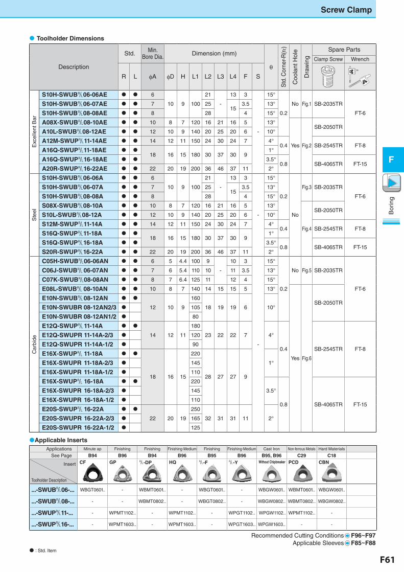
F60 F61
Bor
ing
F
Bor
ing
F
Screw Clamp
: Std. Item
Applicable Inserts
Description
Std. Min. Bore Dia. Dimension (mm)
θ
Std
. Cor
ner-R
(rε)
Coo
lant
Hol
e
Dra
win
g
Spare Parts
Clamp Screw Wrench
R L φA φD H L1 L2 L3 L4 F S
Exc
elle
nt B
ar
S10H-SWUB&06-06AE 6
10 9 100
21
-
13 3
-
15°
0.2
No Fig.1 SB-2035TR
FT-6
S10H-SWUB&06-07AE 7 2515
3.5 13°
S10H-SWUB&08-08AE 8 28 4 15°
A08X-SWUB&08-10AE 10 8 7 120 16 21 16 5 13°
Yes Fig.2
SB-2050TRA10L-SWUB&08-12AE 12 10 9 140 20 25 20 6 10°
A12M-SWUP&11-14AE 14 12 11 150 24 30 24 7 4°0.4 SB-2545TR FT-8
A16Q-SWUP&11-18AE 18 16 15 180 30 37 30 9
1°
A16Q-SWUP&16-18AE 3.5°0.8 SB-4065TR FT-15
A20R-SWUP&16-22AE 22 20 19 200 36 46 37 11 2°
Ste
el
S10H-SWUB&06-06A 6
10 9 100
21
-
13 3
-
15°
0.2
No
Fig.3 SB-2035TR
FT-6
S10H-SWUB&06-07A 7 2515
3.5 13°
S10H-SWUB&08-08A 8 28 4 15°
S08X-SWUB&08-10A 10 8 7 120 16 21 16 5 13°
Fig.4
SB-2050TRS10L-SWUB&08-12A 12 10 9 140 20 25 20 6 10°
S12M-SWUP&11-14A 14 12 11 150 24 30 24 7 4°0.4 SB-2545TR FT-8
S16Q-SWUP&11-18A 18 16 15 180 30 37 30 9
1°
S16Q-SWUP&16-18A 3.5°0.8 SB-4065TR FT-15
S20R-SWUP&16-22A 22 20 19 200 36 46 37 11 2°
Car
bide
C05H-SWUB&06-06AN 6 5 4.4 100 9
-
10 3
-
15°
0.2
No Fig.5 SB-2035TR
FT-6
C06J-SWUB&06-07AN 7 6 5.4 110 10 11 3.5 13°
C07K-SWUB&08-08AN 8 7 6.4 125 11 12 4 15°
E08L-SWUB& 08-10AN 10 8 7 140 14 15 15 5 13°
Yes Fig.6
SB-2050TRE10N-SWUB&08-12AN
12 10 9
160
18 19 19 6 10°E10N-SWUBR 08-12AN2/3 105
E10N-SWUBR 08-12AN1/2 80
E12Q-SWUP&11-14A
14 12 11
180
23 22 22 7 4°
0.4 SB-2545TR FT-8
E12Q-SWUPR11-14A-2/3 120
E12Q-SWUPR11-14A-1/2 90
E16X-SWUP&11-18A
18 16 15
220
28 27 27 9
1°E16X-SWUPR11-18A-2/3 145
E16X-SWUPR11-18A-1/2 110
E16X-SWUP&16-18A 220
3.5°
0.8 SB-4065TR FT-15
E16X-SWUPR16-18A-2/3 145
E16X-SWUPR16-18A-1/2 110
E20S-SWUP&16-22A
22 20 19
250
32 31 31 11 2°E20S-SWUPR16-22A-2/3 165
E20S-SWUPR16-22A-1/2 125
Toolholder Dimensions
Applications Minute ap Finishing Finishing Finishing-Medium Finishing Finishing-Medium Cast Iron Non-ferrous Metals Hard Materials
See Page B94 B96 B94 B96 B95 B96 B95, B96 C29 C18
Insert
Toolholder Description
CF GP &-DP HQ &-F &-Y Without Chipbreaker PCD CBN
...-SWUB&06-... WBGT0601.. - WBMT0601.. - WBGT0601.. - WBGW0601.. WBMT0601.. WBGW0601..
...-SWUB&08-... - - WBMT0802.. - WBGT0802.. - WBGW0802.. WBMT0802.. WBGW0802..
...-SWUP&11-... - WPMT1102.. - WPMT1102.. - WPGT1102.. WPGW1102.. WPMT1102.. -
...-SWUP&16-... - WPMT1603.. - WPMT1603.. - WPGT1603.. WPGW1603.. - -
Recommended Cutting Conditions F96~F97Applicable Sleeves F85~F88
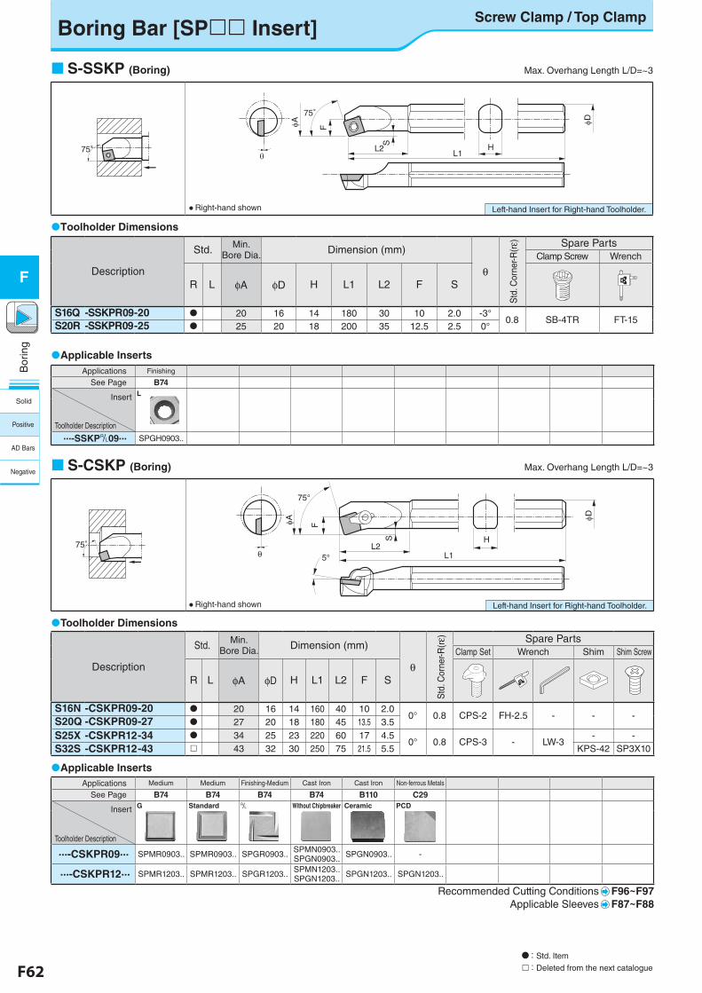
F62 F63
Bor
ing
F
Bor
ing
F
Left-hand Insert for Right-hand Toolholder.
A
S
L2
F
75°
L1H
D
75°
Boring Bar [SP Insert]Screw Clamp / Top Clamp
: Std. Item
: Deleted from the next catalogue
S
A
5°L2
F
75°
L1
H
D
θ75°
Applicable Inserts
S-SSKP (Boring) Max. Overhang Length L/D=~3
Applicable Inserts
Toolholder Dimensions
Toolholder Dimensions
S-CSKP (Boring) Max. Overhang Length L/D=~3
Left-hand Insert for Right-hand Toolholder.
Description
Std. Min. Bore Dia. Dimension (mm)
θ
Std
. Cor
ner-R
(rε) Spare Parts
Clamp Screw Wrench
R L φA φD H L1 L2 F S
S16Q -SSKPR09-20 20 16 14 180 30 10 2.0 -3°0.8 SB-4TR FT-15S20R -SSKPR09-25 25 20 18 200 35 12.5 2.5 0°
Applications Finishing
See Page B74
Insert
Toolholder Description
L
...-SSKP&09... SPGH0903..
Description
Std. Min.Bore Dia. Dimension (mm)
θ
Std
. Cor
ner-R
(rε) Spare Parts
Clamp Set Wrench Shim Shim Screw
R L φA φD H L1 L2 F S
S16N -CSKPR09-20 20 16 14 160 40 10 2.00° 0.8 CPS-2 FH-2.5 - - -S20Q -CSKPR09-27 27 20 18 180 45 13.5 3.5
S25X -CSKPR12-34 34 25 23 220 60 17 4.50° 0.8 CPS-3 - LW-3
- -S32S -CSKPR12-43 43 32 30 250 75 21.5 5.5 KPS-42 SP3X10
Applications Medium Medium Finishing-Medium Cast Iron Cast Iron Non-ferrous Metals
See Page B74 B74 B74 B74 B110 C29
Insert
Toolholder Description
G Standard & Without Chipbreaker Ceramic PCD
...-CSKPR09... SPMR0903.. SPMR0903.. SPGR0903.. SPMN0903.. SPGN0903.. SPGN0903.. -
...-CSKPR12... SPMR1203.. SPMR1203.. SPGR1203.. SPMN1203.. SPGN1203.. SPGN1203.. SPGN1203..
Recommended Cutting Conditions F96~F97Applicable Sleeves F87~F88
● Right-hand shown
● Right-hand shown
Solid
Positive
AD Bars
Negative
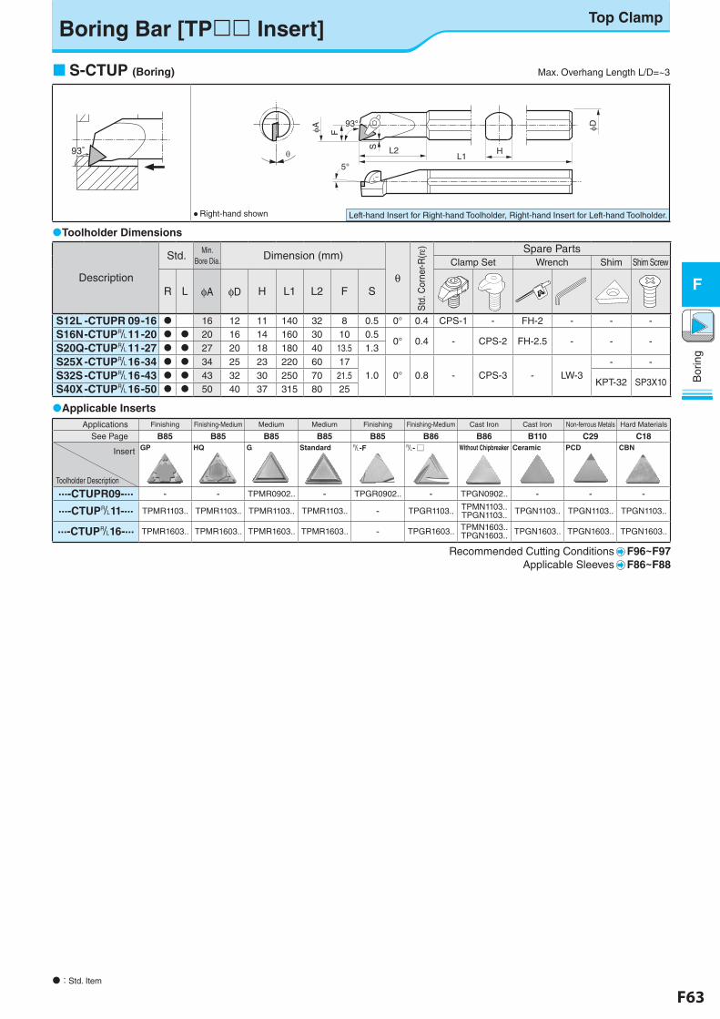
F62 F63
Bor
ing
F
Bor
ing
F
Applications Finishing Finishing-Medium Medium Medium Finishing Finishing-Medium Cast Iron Cast Iron Non-ferrous Metals Hard Materials
See Page B85 B85 B85 B85 B85 B86 B86 B110 C29 C18
Insert
Toolholder Description
GP HQ G Standard &-F &- □ Without Chipbreaker Ceramic PCD CBN
...-CTUPR09-... - - TPMR0902.. - TPGR0902.. - TPGN0902.. - - -
...-CTUP&11-... TPMR1103.. TPMR1103.. TPMR1103.. TPMR1103.. - TPGR1103.. TPMN1103.. TPGN1103.. TPGN1103.. TPGN1103.. TPGN1103..
...-CTUP&16-... TPMR1603.. TPMR1603.. TPMR1603.. TPMR1603.. - TPGR1603.. TPMN1603.. TPGN1603.. TPGN1603.. TPGN1603.. TPGN1603..
Recommended Cutting Conditions F96~F97Applicable Sleeves F86~F88
Description
Std. Min.Bore Dia. Dimension (mm)
θ
Std
. Cor
ner-R
(rε) Spare Parts
Clamp Set Wrench Shim Shim Screw
R L φA φD H L1 L2 F S
S12L -CTUPR 09-16 16 12 11 140 32 8 0.5 0° 0.4 CPS-1 - FH-2 - - -S16N-CTUP& 11-20 20 16 14 160 30 10 0.5
0° 0.4 - CPS-2 FH-2.5 - - -S20Q-CTUP& 11-27 27 20 18 180 40 13.5 1.3
S25X-CTUP& 16-34 34 25 23 220 60 171.0 0° 0.8 - CPS-3 - LW-3
- -
S32S-CTUP& 16-43 43 32 30 250 70 21.5KPT-32 SP3X10
S40X-CTUP& 16-50 50 40 37 315 80 25
Boring Bar [TP Insert]Top Clamp
: Std. Item
F
S
5°
L2
A D
L1H
93°
S-CTUP (Boring) Max. Overhang Length L/D=~3
Applicable Inserts
Toolholder Dimensions
Left-hand Insert for Right-hand Toolholder, Right-hand Insert for Left-hand Toolholder.
● Right-hand shown
93°93°
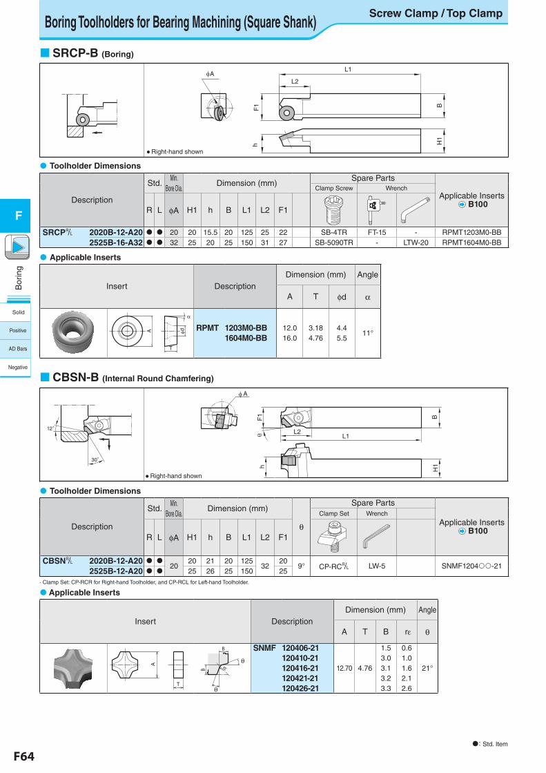
F64 F65
Bor
ing
F
Bor
ing
F
Boring Toolholders for Bearing Machining (Square Shank)Screw Clamp / Top Clamp
SRCP-B (Boring)
CBSN-B (Internal Round Chamfering)
Insert DescriptionDimension (mm) Angle
A T φd α
RPMT 1203M0-BB1604M0-BB
12.016.0
3.184.76
4.45.5
11°
T
A φd
α
Toolholder Dimensions
Description
Std.Min.
Bore Dia.Dimension (mm)
Spare Parts
Applicable Inserts B100
Clamp Screw Wrench
R L φA H1 h B L1 L2 F1
SRCP& 2020B-12-A20 20 20 15.5 20 125 25 22 SB-4TR FT-15 - RPMT1203M0-BB2525B-16-A32 32 25 20 25 150 31 27 SB-5090TR - LTW-20 RPMT1604M0-BB
Toolholder Dimensions
Description
Std.Min.
Bore Dia.Dimension (mm)
θ
Spare Parts
Applicable Inserts B100
Clamp Set Wrench
R L φA H1 h B L1 L2 F1
CBSN& 2020B-12-A20 20
20 21 20 12532
209° CP-RC& LW-5 SNMF1204-21
2525B-12-A20 25 26 25 150 25· Clamp Set: CP-RCR for Right-hand Toolholder, and CP-RCL for Left-hand Toolholder.
Applicable Inserts
A
hF
1
L2
L1
H1
B
● Right-hand shown
Insert DescriptionDimension (mm) Angle
A T B rε θ
SNMF 120406-21120410-21120416-21120421-21120426-21
12.70 4.76
1.53.03.13.23.3
0.61.01.62.12.6
21°
A
T
B
θ
rεθ
B
Applicable Inserts
12゜
30゜
L2
F1 B
L1
A
h H1
● Right-hand shown
: Std. Item
Solid
Positive
AD Bars
Negative
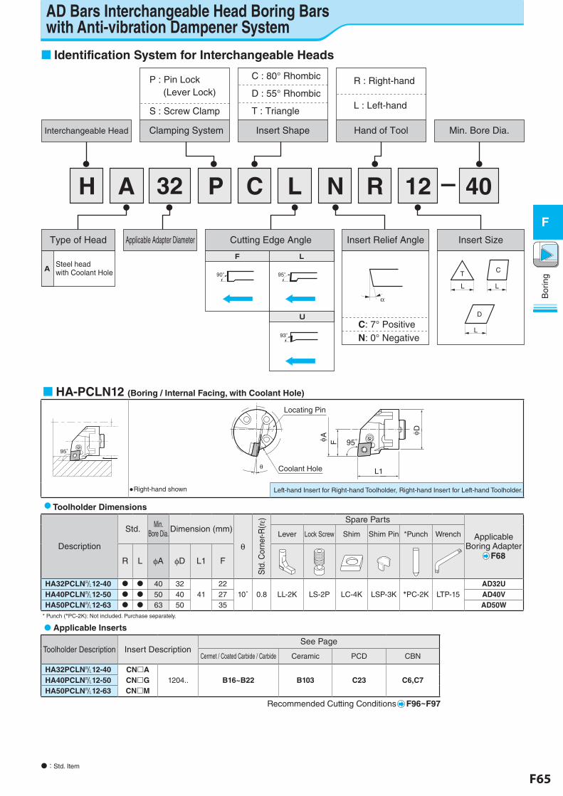
F64 F65
Bor
ing
F
Bor
ing
F
AD Bars Interchangeable Head Boring Bars with Anti-vibration Dampener System
Identification System for Interchangeable Heads
N R 12 40C LP32H A -
Type of Head Applicable Adapter Diameter Cutting Edge Angle Insert Relief Angle Insert Size
Insert Shape Hand of ToolClamping System Min. Bore Dia.Interchangeable Head
C : 80° Rhombic
D : 55° Rhombic
T : Triangle
R : Right-hand
L : Left-hand (Lever Lock)
Steel headwith Coolant HoleA
F L
U
LF
90° 95°
93°
α
C: 7° PositiveN: 0° Negative
D
L
T
L
C
L
S : Screw Clamp
P : Pin Lock
HA-PCLN12 (Boring / Internal Facing, with Coolant Hole)
95゚
Locating Pin
θ
AF
D
L1
95°
Coolant Hole
●Right-hand shown Left-hand Insert for Right-hand Toolholder, Right-hand Insert for Left-hand Toolholder.
Toolholder Dimensions
Description
Std. Min.Bore Dia. Dimension (mm)
θ
Std
. Cor
ner-R
(rε) Spare Parts
Applicable Boring Adapter
F68
Lever Lock Screw Shim Shim Pin *Punch Wrench
R L φA φD L1 F
HA32PCLN&12-40 40 3241
2210˚ 0.8 LL-2K LS-2P LC-4K LSP-3K *PC-2K LTP-15
AD32UHA40PCLN&12-50 50 40 27 AD40VHA50PCLN&12-63 63 50 35 AD50W
* Punch (*PC-2K): Not included. Purchase separately.
Applicable Inserts
Toolholder Description Insert DescriptionSee Page
Cermet / Coated Carbide / Carbide Ceramic PCD CBN
HA32PCLN&12-40 CNA1204.. B16~B22 B103 C23 C6,C7HA40PCLN&12-50 CNG
HA50PCLN&12-63 CNM
Recommended Cutting Conditions F96~F97
: Std. Item
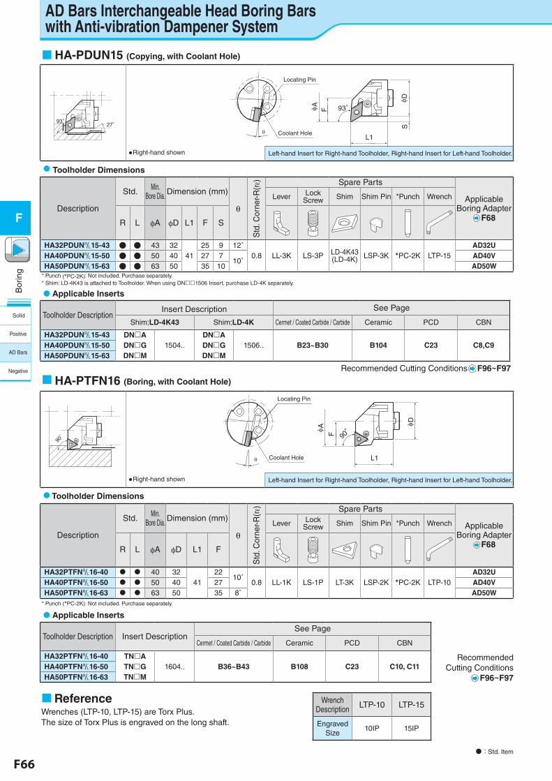
F66 F67
Bor
ing
F
Bor
ing
F
AD Bars Interchangeable Head Boring Bars with Anti-vibration Dampener System
HA-PDUN15 (Copying, with Coolant Hole)
93゚27゚
Locating Pin
93゚AF
SD
L1Coolant Hole
●Right-hand shown Left-hand Insert for Right-hand Toolholder, Right-hand Insert for Left-hand Toolholder.
Toolholder Dimensions
Description
Std. Min.Bore Dia. Dimension (mm)
θ
Std
. Cor
ner-R
(rε) Spare Parts
Applicable Boring Adapter
F68
Lever Lock Screw Shim Shim Pin *Punch Wrench
R L φA φD L1 F S
HA32PDUN&15-43 ● ● 43 3241
25 9 12˚0.8 LL-3K LS-3P LD-4K43
(LD-4K) LSP-3K *PC-2K LTP-15AD32U
HA40PDUN&15-50 ● ● 50 40 27 710˚
AD40VHA50PDUN&15-63 ● ● 63 50 35 10 AD50W
* Punch (*PC-2K): Not included. Purchase separately.* Shim: LD-4K43 is attached to Toolholder. When using DN1506 Insert, purchase LD-4K separately.
Applicable Inserts
Toolholder DescriptionInsert Description See Page
Shim:LD-4K43 Shim:LD-4K Cermet / Coated Carbide / Carbide Ceramic PCD CBN
HA32PDUN&15-43 DNA1504..
DNA1506.. B23~B30 B104 C23 C8,C9HA40PDUN&15-50 DNG DNG
HA50PDUN&15-63 DNM DNM
Recommended Cutting Conditions F96~F97
HA-PTFN16 (Boring, with Coolant Hole)
90゚
Locating Pin
90゚
A
F
D
L1Coolant Hole
●Right-hand shown Left-hand Insert for Right-hand Toolholder, Right-hand Insert for Left-hand Toolholder.
Toolholder Dimensions
Description
Std. Min.Bore Dia. Dimension (mm)
θ
Std
. Cor
ner-R
(rε) Spare Parts
Applicable Boring Adapter
F68
Lever Lock Screw Shim Shim Pin *Punch Wrench
R L φA φD L1 F
HA32PTFN&16-40 40 3241
2210˚
0.8 LL-1K LS-1P LT-3K LSP-2K *PC-2K LTP-10AD32U
HA40PTFN&16-50 50 40 27 AD40VHA50PTFN&16-63 63 50 35 8˚ AD50W
* Punch (*PC-2K): Not included. Purchase separately.
Applicable Inserts
Toolholder Description Insert DescriptionSee Page
Cermet / Coated Carbide / Carbide Ceramic PCD CBN
HA32PTFN&16-40 TNA1604.. B36~B43 B108 C23 C10, C11HA40PTFN&16-50 TNG
HA50PTFN&16-63 TNM
: Std. Item
ReferenceWrenches (LTP-10, LTP-15) are Torx Plus.The size of Torx Plus is engraved on the long shaft.
Wrench Description LTP-10 LTP-15
Engraved Size
10IP 15IP
Recommended Cutting Conditions
F96~F97
Solid
Positive
AD Bars
Negative
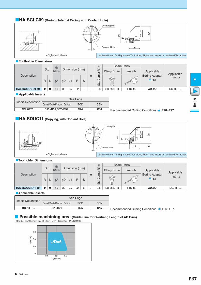
F66 F67
Bor
ing
F
Bor
ing
F
HA-SCLC09 (Boring / Internal Facing, with Coolant Hole)
95゚
Locating Pin
95゚
θ
φA
φD
L1Coolant Hole
F
●Right-hand shown Left-hand Insert for Right-hand Toolholder, Right-hand Insert for Left-hand Toolholder.
Toolholder Dimensions
Description
Std. Min.Bore Dia. Dimension (mm)
θ
Std
. Cor
ner-R
(rε) Spare Parts
ApplicableBoring Adapter
F68
Applicable Inserts
Clamp Screw Wrench
R L φA φD L1 F S
HA32SCLC&09-40 40 32 25 22 - 3˚ 0.8 SB-3580TR FTS-15 AD32U CC..09T3..
HA-SDUC11 (Copying, with Coolant Hole)
93゚93゚ 30゚
Locating Pin
93゚
θ
φ A F
φ DL1 SCoolant Hole
●Right-hand shown Left-hand Insert for Right-hand Toolholder, Right-hand Insert for Left-hand Toolholder.
Toolholder Dimensions
Description
Std. Min.Bore Dia. Dimension (mm)
θ
Std
. Cor
ner-R
(rε) Spare Parts
ApplicableBoring Adapter
F68
Applicable Inserts
Clamp Screw Wrench
R L φA φD L1 F S
HA32SDUC&11-40 40 32 25 22 6 3˚ 0.8 SB-3580TR FTS-15 AD32U DC..11T3..
Possible machining area (Guide-Line for Overhang Length of AD Bars)(SCM435 Vc=150m/min ap=0.5~3mm f=0.1~0.3mm/rev TNMG160408)
3.0
2.0
1.0
00.1 0.2 0.3
f (mm/rev)
L/D=6 ap
(mm
)
Applicable Inserts
Insert DescriptionSee Page
Cermet / Coated Carbide / Carbide PCD CBN
DC..11T3.. B61~B70 C25 C15
Applicable Inserts
Insert DescriptionSee Page
Cermet / Coated Carbide / Carbide PCD CBN
CC..09T3.. B53~B55,B57~B59 C24 C14
: Std. Item
Recommended Cutting Conditions F96~F97
Recommended Cutting Conditions F96~F97
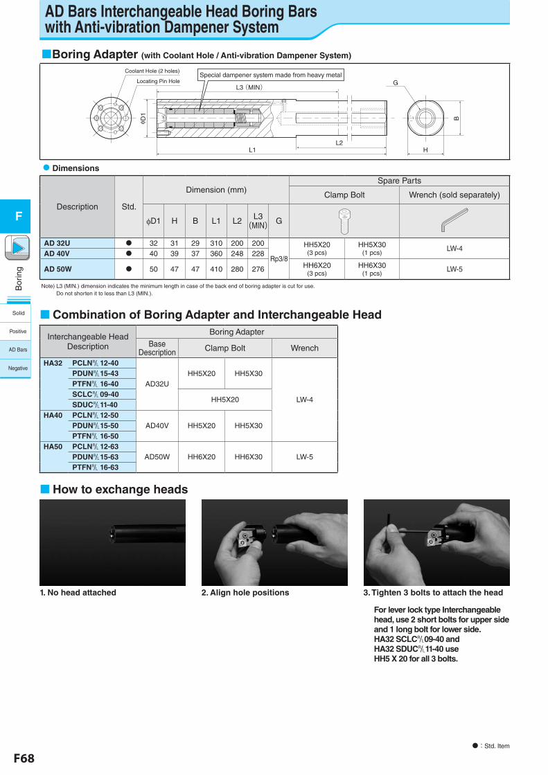
F68 F69
Bor
ing
F
Bor
ing
F
Boring Adapter (with Coolant Hole / Anti-vibration Dampener System)
L1
φ D1
L2
L3 (MIN)
B
H
G
Coolant Hole (2 holes)
Locating Pin HoleSpecial dampener system made from heavy metal
Dimensions
Description Std.
Dimension (mm)Spare Parts
Clamp Bolt Wrench (sold separately)
φD1 H B L1 L2 L3(MIN) G
AD 32U 32 31 29 310 200 200
Rp3/8
HH5X20(3 pcs)
HH5X30(1 pcs)
LW-4AD 40V 40 39 37 360 248 228
AD 50W 50 47 47 410 280 276 HH6X20(3 pcs)
HH6X30(1 pcs)
LW-5
Note) L3 (MIN.) dimension indicates the minimum length in case of the back end of boring adapter is cut for use. Do not shorten it to less than L3 (MIN.).
How to exchange heads
1. No head attached 2. Align hole positions 3. Tighten 3 bolts to attach the head
For lever lock type Interchangeable head, use 2 short bolts for upper side and 1 long bolt for lower side.HA32 SCLC&09-40 and HA32 SDUC&11-40 use HH5 X 20 for all 3 bolts.
: Std. Item
Combination of Boring Adapter and Interchangeable Head
Interchangeable Head Description
Boring Adapter
BaseDescription Clamp Bolt Wrench
HA32 PCLN&12-40
AD32UHH5X20 HH5X30
LW-4
PDUN&15-43PTFN& 16-40SCLC&09-40
HH5X20SDUC&11-40
HA40 PCLN&12-50AD40V HH5X20 HH5X30PDUN&15-50
PTFN& 16-50HA50 PCLN&12-63
AD50W HH6X20 HH6X30 LW-5PDUN&15-63PTFN& 16-63
AD Bars Interchangeable Head Boring Bars with Anti-vibration Dampener System
Solid
Positive
AD Bars
Negative
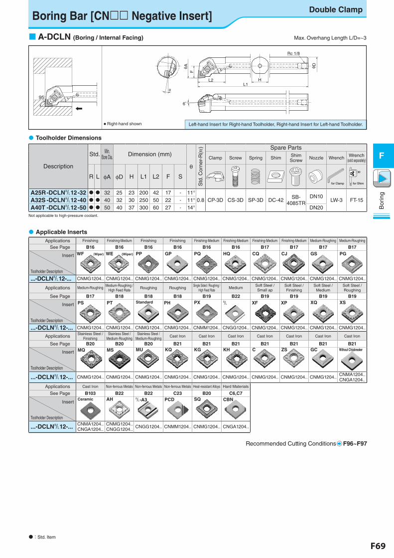
F68 F69
Bor
ing
F
Bor
ing
F
Applications Finishing Finishing-Medium Finishing Finishing Finishing-Medium Finishing-Medium Finishing-Medium Finishing-Medium Medium-Roughing Medium-Roughing
See Page B16 B16 B16 B16 B16 B16 B17 B17 B17 B17
Insert
Toolholder Description
WF (Wiper) WE (Wiper) PP GP PQ HQ CQ CJ GS PG
...-DCLN&12-... CNMG1204.. CNMG1204.. CNMG1204.. CNMG1204.. CNMG1204.. CNMG1204.. CNMG1204.. CNMG1204.. CNMG1204.. CNMG1204..
Applications Medium-Roughing Medium-Roughing /High Feed Rate
Roughing RoughingSingle Sided / Roughing /
High Feed RateMedium
Soft Steel /Small ap
Soft Steel /Finishing
Soft Steel / Medium
Soft Steel / Roughing
See Page B17 B18 B18 B18 B19 B22 B19 B19 B19 B19
Insert
Toolholder Description
PS PT Standard PH PX & XF XP XQ XS
...-DCLN&12-... CNMG1204.. CNMG1204.. CNMG1204.. CNMG1204.. CNMM1204.. CNGG1204.. CNMG1204.. CNMG1204.. CNMG1204.. CNMG1204..
Applications Stainless Steel /Finishing
Stainless Steel /Medium-Roughing
Stainless Steel /Medium-Roughing
Cast Iron Cast Iron Cast Iron Cast Iron Cast Iron Cast Iron Cast Iron
See Page B20 B20 B20 B21 B21 B21 B21 B21 B21 B21
Insert
Toolholder Description
MQ MS MU KQ KG KH C ZS GC Without Chipbreaker
...-DCLN&12-... CNMG1204.. CNMG1204.. CNMG1204.. CNMG1204.. CNMG1204.. CNMG1204.. CNMG1204.. CNMG1204.. CNMG1204.. CNMA1204.. CNGA1204..
Applications Cast Iron Non-ferrous Metals Non-ferrous Metals Non-ferrous Metals Heat-resistant Alloys Hard Materials
See Page B103 B22 B22 C23 B20 C6,C7
Insert
Toolholder Description
Ceramic AH &-A3 PCD SQ CBN
...-DCLN&12-... CNMA1204.. CNGA1204..
CNMG1204..CNGG1204.. CNGG1204.. CNMM1204.. CNMG1204.. CNGA1204..
Recommended Cutting Conditions F96~F97
Left-hand Insert for Right-hand Toolholder, Right-hand Insert for Left-hand Toolholder.● Right-hand shown
Boring Bar [CN Negative Insert]Double Clamp
A-DCLN (Boring / Internal Facing) Max. Overhang Length L/D=~3
Description
Std. Min.Bore Dia. Dimension (mm)
θ
Std
. Cor
ner-
R(rε) Spare Parts
Clamp Screw Spring Shim Shim Screw Nozzle Wrench Wrench
(sold separately)
R L φA φD H L1 L2 F S
A25R-DCLN&12-32 32 25 23 200 42 17 - 11°0.8 CP-3D CS-3D SP-3D DC-42 SB-
4085TRDN10
LW-3 FT-15A32S -DCLN&12-40 40 32 30 250 50 22 - 11°A40T -DCLN&12-50 50 40 37 300 60 27 - 14° DN20
Not applicable to high-pressure coolant.
Toolholder Dimensions
Applicable Inserts
: Std. Item
95°95°
F
L1
φ A
6゜
θ
L2 H
Rc 1/8
φ D
for Clamp for Shim
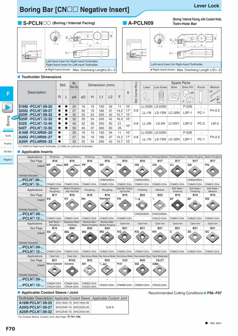
F70 F71
Bor
ing
F
Bor
ing
F
Boring Bar [CN Negative Insert]Lever Lock
● : Std. Item
Left-hand Insert for Right-hand Toolholder, Right-hand Insert for Left-hand Toolholder.
F
6゜
θ
A
L2L1
95゜
H
D
95゜
S-PCLN (Boring / Internal Facing)
Max. Overhang LengthL/D=~3● Right-hand shown
Description
Std. Min.Bore Dia. Dimension (mm)
θ
Std
. Cor
ner-R
(rε) Spare Parts
Lever Lock Screw Shim Shim Pin Punch Wrench
R L φA φD H L1 L2 FLSP
P
LW
FH
S16M -PCLN&09-20 20 16 15 150 34 11 16°0.8
LL-03SN LS-03SN - P-03S -
FH-2.5S20Q -PCLN&09-27 27 20 19 180 37 14.2 17°LL-1N LS-1SN LC-32N LSP-1 PC-1S25R -PCLN&09-32 32 25 24 200 42 15.7 15°
S25R -PCLN&12-32 32 25 24 200 42 16.3 16°0.8 LL-2N LS-2N LC-42N& LSP-2 PC-2 LW-3S32S -PCLN&12-40 40 32 30 250 50 21
10°S40T -PCLN&12-50 50 40 37 300 60 25
A16M -PCLNR09 -20 20 16 15 150 34 11 16°0.8
LL-03SN LS-03SN - P-03S -
FH-2.5A20Q -PCLNR09 -27 27 20 19 180 37 14.2 17°LL-1N LS-1SN LC-32N LSP-1 PC-1
A25R -PCLNR09 -32 32 25 24 200 42 15.7 15°· LC-42NR for Right-hand Toolholder, LC-42NL for Left-hand Toolholder.
Toolholder Dimensions
Toolholder Description Applicable Coolant Sleeve Applicable Coolant JointA16M-PCLN&09-20 SHC1640-70, SHC1650-95
SJS-8A20Q-PCLN&09-27 SHC2040-70, SHC2050-95
A25R-PCLN&09-32 SHC2540-70, SHC2550-95
· For Coolant Sleeve, Coolant Joint, See Page F87~F88.
Applicable Coolant Sleeve / Joint
Left-hand Insert for Right-hand Toolholder.
6゜
F
θ
A
L2L1
95゜
H
D
95゜
A-PCLN09
Max. Overhang Length L/D=~3● Right-hand shown
(Boring / Internal Facing, with Coolant Hole) Twin-Hole Bar
Applicable InsertsApplications Finishing Finishing-Medium Finishing Finishing Finishing-Medium Finishing-Medium Finishing-Medium Finishing-Medium Medium-Roughing Medium-Roughing
See Page B16 B16 B16 B16 B16 B16 B17 B17 B17 B17
Insert
Toolholder Description
WF (Wiper) WE (Wiper) PP GP PQ HQ CQ CJ GS PG
...-PCLN&09-... - - - CNMG0904.. - CNMG0904.. - - CNMG0904.. -
...-PCLN&12-... CNMG1204.. CNMG1204.. CNMG1204.. CNMG1204.. CNMG1204.. CNMG1204.. CNMG1204.. CNMG1204.. CNMG1204.. CNMG1204..
Applications Medium-Roughing
Medium-Roughing /High Feed Rate Roughing Roughing
Single Sided / Roughing /High Feed Rate
Finishing MediumSoft Steel / Small ap
Soft Steel / Finishing
Soft Steel / Medium
See Page B17 B18 B18 B18 B19 B22 B22 B19 B19 B19
Insert
Toolholder Description
PS PT PH Standard PX &-S & XF XP XQ
...-PCLN&09-... - - - - - CNGG0904.. CNGG0904.. - - -
...-PCLN&12-... CNMG1204.. CNMG1204.. CNMG1204.. CNMG1204.. CNMM1204.. - CNGG1204.. CNMG1204.. CNMG1204.. CNMG1204..
Applications Soft Steel / Roughing
Stainless Steel /Finishing
Stainless Steel / Medium-Roughing
Stainless Steel / Medium-Roughing
Cast Iron Cast Iron Cast Iron Cast Iron Cast Iron Cast Iron
See Page B19 B20 B20 B20 B21 B21 B21 B21 B21 B21
Insert
Toolholder Description
XS MQ MS MU KQ KG KH C ZS GC
...-PCLN&09-... - - - - - - - - - -
...-PCLN&12-... CNMG1204.. CNMG1204.. CNMG1204.. CNMG1204.. CNMG1204.. CNMG1204.. CNMG1204.. CNMG1204.. CNMG1204.. CNMG1204..
Applications Cast Iron Cast Iron Non-ferrous Metals Non-ferrous Metals Non-ferrous Metals Heat-resistant Alloys Hard Materials
See Page B21 B103 B22 B22 C23 B20 C6,C7
Insert
Toolholder Description
Without Chipbreaker Ceramic AH &-A3 PCD SQ CBN
...-PCLN&09-... - - - - - - -
...-PCLN&12-... CNMA1204.. CNGA1204..
CNMA1204.. CNGA1204..
CNMG1204..CNGG1204.. CNGG1204.. CNMM1204.. CNMG1204.. CNGA1204..
Recommended Cutting Conditions F96~F97
Solid
Positive
AD Bars
Negative
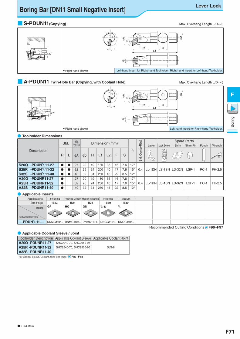
F70 F71
Bor
ing
F
Bor
ing
F
θ
6°
FφA
L2 HL1
φD
S
93°
Boring Bar [DN11 Small Negative Insert]Lever Lock
● : Std. Item
Left-hand Insert for Right-hand Toolholder, Right-hand Insert for Left-hand Toolholder.
27°93°93°
■ S-PDUN11(Copying) Max. Overhang Length L/D=~3
● Right-hand shown
6°φA
θ
F
L1H
φD
S
L2
93°
27°93°93°
Left-hand Insert for Right-hand Toolholder.
■ A-PDUN11 Twin-Hole Bar (Copying, with Coolant Hole) Max. Overhang Length L/D=~3
● Right-hand shown
Toolholder Description Applicable Coolant Sleeve Applicable Coolant JointA20Q -PDUNR11-27 SHC2040-70, SHC2050-95
SJS-8A25R -PDUNR11-32 SHC2540-70, SHC2550-95
A32S -PDUNR11-40 -
· For Coolant Sleeve, Coolant Joint, See Page F87~F88
● Applicable Coolant Sleeve / Joint
Applications Finishing Finishing-Medium Medium-Roughing Finishing Medium
See Page B23 B24 B24 B30 B30
Insert
Toolholder Description
GP HQ GS &-S &
...-PDUN&11-... DNMG1104.. DNMG1104.. DNMG1104.. DNGG1104.. DNGG1104..
Recommended Cutting Conditions F96~F97
● Applicable Inserts
● Toolholder Dimensions
Description
Std. Min. Bore Dia. Dimension (mm)
θ
Std
. Cor
ner-R
(rε) Spare Parts
Lever Lock Screw Shim Shim Pin Punch Wrench
R L φA φD H L1 L2 F S
S20Q -PDUN&11-27 ● ● 27 20 19 180 35 16 7.6 17°0.4 LL-1DN LS-1SN LD-32N LSP-1 PC-1 FH-2.5S25R -PDUN&11-32 ● ● 32 25 24 200 40 17 7.6 15°
S32S -PDUN&11-40 ● ● 40 32 31 250 45 22 8.5 12°
A20Q -PDUNR11-27 ● 27 20 19 180 35 16 7.6 17°0.4 LL-1DN LS-1SN LD-32N LSP-1 PC-1 FH-2.5A25R -PDUNR11-32 ● 32 25 24 200 40 17 7.6 15°
A32S -PDUNR11-40 ● 40 32 31 250 45 22 8.5 12°
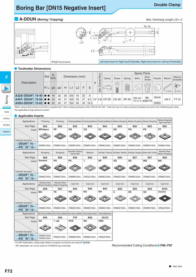
F72 F73
Bor
ing
F
Bor
ing
F
Applications *Finishing Finishing Finishing-Medium Finishing-Medium Finishing-Medium Medium-Roughing Medium-Roughing Medium-RoughingMedium-Roughing/
High Feed Rate
See Page B23 B23 B23 B24 B24 B24 B25 B25 B25
Insert
Toolholder Description
WF(Wiper) PP PQ CQ CJ GS PG PS PT
...-DDUN&15-...DNMX1504.. DNMG1504.. DNMG1504.. DNMG1504.. DNMG1504.. DNMG1504.. DNMG1504.. DNMG1504.. DNMG1504.....-PD□N&15-...
Applications Roughing RoughingSingle Sided / Roughing/
High Feed RateMedium Soft Steel / Finishing Soft Steel / Medium Soft Steel / Roughing Stainless Steel / Finishing
Stainless Steel/Medium-Roughing
See Page B26 B26 B26 B30 B26 B26 B27 B27 B28
Insert
Toolholder Description
Standard PH PX & XP XQ XS MQ MS
...-DDUN&15-...DNMG1504.. DNMG1504.. DNMM1504.. DNGG1504.. DNMG1504.. DNMG1504.. DNMG1504.. DNMG1504.. DNMG1504.....-PD□N&15-...
Applications Stainless Steel/Medium-Roughing
Stainless Steel/ Medium-Roughing
Cast Iron Cast Iron Cast Iron Cast Iron Cast Iron Cast Iron Cast Iron
See Page B28 B27 B29 B29 B29 B29 B29 B30 B104
Insert
Toolholder Description
MU TK KQ KG KH C ZS GC Ceramic
...-DDUN&15-...DNMG1504.. DNMG1504.. DNMG1504.. DNMG1504.. DNMG1504.. DNMG1504.. DNMG1504.. DNMG1504.. DNGA1504.....-PD□N&15-...
Applications Non-ferrous Metals Non-ferrous Metals Non-ferrous Metals Heat-resistant Alloys Hard Materials
See Page B30 B30 C23 B28 C8,C9
Insert
Toolholder Description
AH &-A3 PCD SQ CBN
...-DDUN&15-... DNMG1504..DNGG1504.. DNGG1504.. DNMM1504.. DNMG1504.. DNGA1504.....-PD□N&15-...
Recommended Cutting Conditions F96~F97
Left-hand Insert for Right-hand Toolholder, Right-hand Insert for Left-hand Toolholder.● Right-hand shown
Boring Bar [DN15 Negative Insert]Double Clamp
● : Std. Item
■ A-DDUN (Boring / Copying) Max. Overhang Length L/D=~3
Description
Std. Min. Bore Dia. Dimension (mm)
θ
Std
. Cor
ner-
R(rε) Spare Parts
Clamp Screw Spring Shim Shim Screw Nozzle Wrench Wrench
(sold separately)
R L φA φD H L1 L2 F S
A32S- DDUN&15-40 ● ● 40 32 30 250 45 22 812° 0.8 CP-3D CS-3D SP-3D DD-42
*DD-42-16
SB-4085TR
DN10LW-3 FT-15A40T- DDUN&15-50 ● ● 50 40 37 300 55 27 8.5
A50U-DDUN&15-63 ● ● 63 50 47 350 65 35 10.5 DN20*When using inserts whose corner-R(rε) is greater than 1.6mm, please purchase a shim (DD-42-16) with * mark and use it in order to prevent workpiece and shim from interfering each other.
*Not applicable to high-pressure coolant.
● Toolholder Dimensions
27°
93°
93°
φA
6゜
Rc 1/8
φD
HL1
L2
S
θ
Ffor Clamp for Shim
● Applicable Inserts
* For WF chipbreaker, cutting edge offsets or program corrections are required F74 WF chipbreaker can not be used for S-PDQN15 type toolholder
Solid
Positive
AD Bars
Negative
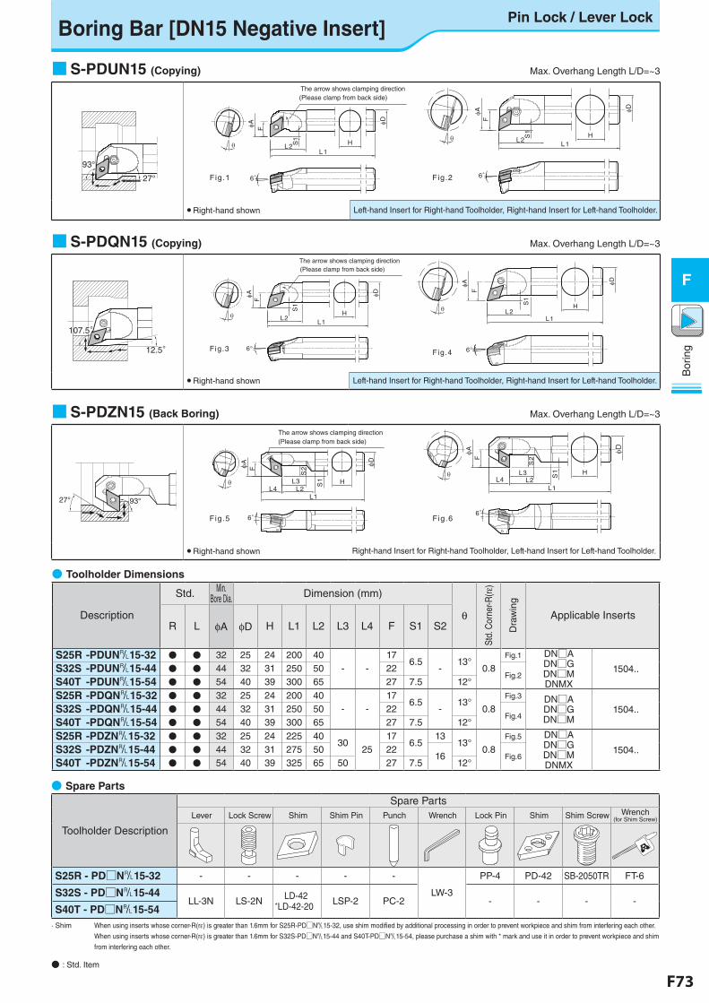
F72 F73
Bor
ing
F
Bor
ing
F
■ S-PDUN15 (Copying) Max. Overhang Length L/D=~3
■ S-PDQN15 (Copying) Max. Overhang Length L/D=~3
● Toolholder Dimensions
Description
Std. Min. Bore Dia. Dimension (mm)
θ
Std.
Cor
ner-R
(rε)
Dra
win
g
Applicable InsertsR L φA φD H L1 L2 L3 L4 F S1 S2
S25R -PDUN&15-32 ● ● 32 25 24 200 40- -
176.5
-13°
0.8Fig.1 DN□A
DN□GDN□MDNMX
1504..S32S -PDUN&15-44 ● ● 44 32 31 250 50 22Fig.2
S40T -PDUN&15-54 ● ● 54 40 39 300 65 27 7.5 12°
S25R -PDQN&15-32 ● ● 32 25 24 200 40- -
176.5
-13°
0.8Fig.3 DN□A
DN□GDN□M
1504..S32S -PDQN&15-44 ● ● 44 32 31 250 50 22Fig.4
S40T -PDQN&15-54 ● ● 54 40 39 300 65 27 7.5 12°
S25R -PDZN&15-32 ● ● 32 25 24 225 4030
2517
6.513
13°0.8
Fig.5 DN□ADN□GDN□MDNMX
1504..S32S -PDZN&15-44 ● ● 44 32 31 275 50 2216 Fig.6
S40T -PDZN&15-54 ● ● 54 40 39 325 65 50 27 7.5 12°
27°
93°
F
A
HL2L1
D
6°
The arrow shows clamping direction(Please clamp from back side)
S1 HS
1
L1
D
6°
FA
L2
Fig.1 Fig.2
● Right-hand shown Left-hand Insert for Right-hand Toolholder, Right-hand Insert for Left-hand Toolholder.
107.5°107.5°
12.5°
H
D
S1
L1
6°
AF
L2
Fig.3
The arrow shows clamping direction(Please clamp from back side)
6°
D
HS1
L2L1
F
A
F ig.4
● Right-hand shown Left-hand Insert for Right-hand Toolholder, Right-hand Insert for Left-hand Toolholder.
■ S-PDZN15 (Back Boring) Max. Overhang Length L/D=~3
27° 93°
D
S1 HL3
S2
L2L4
FA
L1
6°
The arrow shows clamping direction(Please clamp from back side)
Fig.56°
D
HS1
S2
L3L4 L2
FA
L1
Fig.6
● Right-hand shown Right-hand Insert for Right-hand Toolholder, Left-hand Insert for Left-hand Toolholder.
Boring Bar [DN15 Negative Insert]Pin Lock / Lever Lock
● : Std. Item
● Spare Parts
Toolholder Description
Spare PartsLever Lock Screw Shim Shim Pin Punch Wrench Lock Pin Shim Shim Screw Wrench
(for Shim Screw)
S25R - PD□N&15-32 - - - - -
LW-3
PP-4 PD-42 SB-2050TR FT-6
S32S - PD□N&15-44LL-3N LS-2N LD-42
*LD-42-20 LSP-2 PC-2 - - - -S40T - PD□N&15-54
· Shim When using inserts whose corner-R(rε) is greater than 1.6mm for S25R-PD□N&15-32, use shim modified by additional processing in order to prevent workpiece and shim from interfering each other.
When using inserts whose corner-R(rε) is greater than 1.6mm for S32S-PD□N&15-44 and S40T-PD□N&15-54, please purchase a shim with * mark and use it in order to prevent workpiece and shim
from interfering each other.
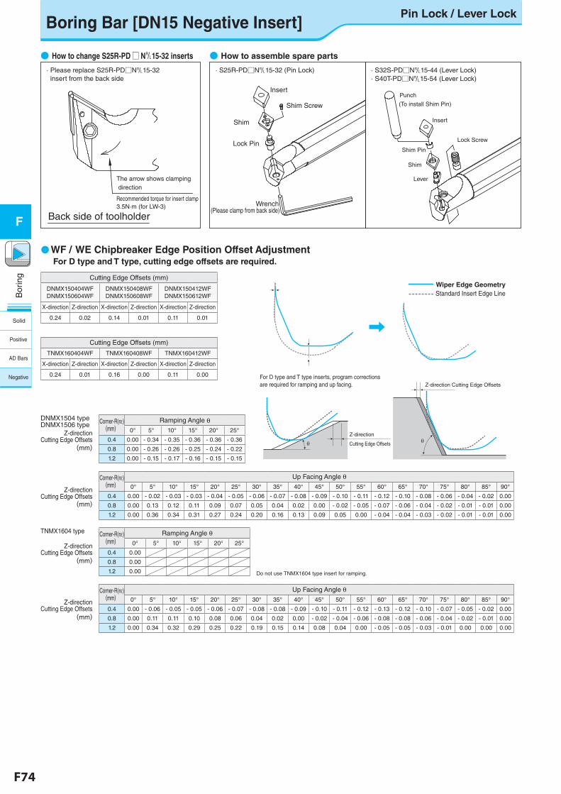
F74 F75
Bor
ing
F
Bor
ing
F
Boring Bar [DN15 Negative Insert]Pin Lock / Lever Lock
● How to change S25R-PD □ N&15-32 inserts ● How to assemble spare parts
Back side of toolholder
The arrow shows clamping direction
Recommended torque for insert clamp3.5N·m (for LW-3)
· Please replace S25R-PD□N&15-32 insert from the back side
· S25R-PD□N&15-32 (Pin Lock)
Insert
Shim Screw
Shim
Lock Pin
Wrench(Please clamp from back side)
Lock Screw
Insert
Shim Pin
Shim
Lever
Punch
(To install Shim Pin)
· S32S-PD□N&15-44 (Lever Lock)· S40T-PD□N&15-54 (Lever Lock)
●WF / WE Chipbreaker Edge Position Offset Adjustment
Corner-R(rε)(mm)
Up Facing Angle θ0° 5° 10° 15° 20° 25° 30° 35° 40° 45° 50° 55° 60° 65° 70° 75° 80° 85° 90°
0.4 0.00 - 0.06 - 0.05 - 0.05 - 0.06 - 0.07 - 0.08 - 0.08 - 0.09 - 0.10 - 0.11 - 0.12 - 0.13 - 0.12 - 0.10 - 0.07 - 0.05 - 0.02 0.00
0.8 0.00 0.11 0.11 0.10 0.08 0.06 0.04 0.02 0.00 - 0.02 - 0.04 - 0.06 - 0.08 - 0.08 - 0.06 - 0.04 - 0.02 - 0.01 0.00
1.2 0.00 0.34 0.32 0.29 0.25 0.22 0.19 0.15 0.14 0.08 0.04 0.00 - 0.05 - 0.05 - 0.03 - 0.01 0.00 0.00 0.00
Z-direction Cutting Edge Offsets
Z-direction Cutting Edge Offsets
Corner-R(rε)(mm)
Up Facing Angle θ0° 5° 10° 15° 20° 25° 30° 35° 40° 45° 50° 55° 60° 65° 70° 75° 80° 85° 90°
0.4 0.00 - 0.02 - 0.03 - 0.03 - 0.04 - 0.05 - 0.06 - 0.07 - 0.08 - 0.09 - 0.10 - 0.11 - 0.12 - 0.10 - 0.08 - 0.06 - 0.04 - 0.02 0.00
0.8 0.00 0.13 0.12 0.11 0.09 0.07 0.05 0.04 0.02 0.00 - 0.02 - 0.05 - 0.07 - 0.06 - 0.04 - 0.02 - 0.01 - 0.01 0.00
1.2 0.00 0.36 0.34 0.31 0.27 0.24 0.20 0.16 0.13 0.09 0.05 0.00 - 0.04 - 0.04 - 0.03 - 0.02 - 0.01 - 0.01 0.00
Z-direction Cutting Edge Offsets
Z-direction Cutting Edge Offsets
Corner-R(rε)(mm)
Ramping Angle θ0° 5° 10° 15° 20° 25°
0.4 0.00 - 0.34 - 0.35 - 0.36 - 0.36 - 0.36
0.8 0.00 - 0.26 - 0.26 - 0.25 - 0.24 - 0.22
1.2 0.00 - 0.15 - 0.17 - 0.16 - 0.15 - 0.15
Cutting Edge Offsets (mm)
TNMX160404WF TNMX160408WF TNMX160412WF
X-direction Z-direction X-direction Z-direction X-direction Z-direction
0.24 0.01 0.16 0.00 0.11 0.00
Cutting Edge Offsets (mm)
DNMX150404WFDNMX150604WF
DNMX150408WFDNMX150608WF
DNMX150412WFDNMX150612WF
X-direction Z-direction X-direction Z-direction X-direction Z-direction
0.24 0.02 0.14 0.01 0.11 0.01
DNMX1504 typeDNMX1506 type
Corner-R(rε)(mm)
Ramping Angle θ0° 5° 10° 15° 20° 25°
0.4 0.00
0.8 0.00
1.2 0.00
TNMX1604 type
Do not use TNMX1604 type insert for ramping.
(mm)
(mm)
(mm)
(mm)
Wiper Edge GeometryStandard Insert Edge Line
D・Tタイプは、刃先位置の補正が必要です
For D type and T type inserts, program corrections are required for ramping and up facing.
Z-direction
Cutting Edge Offsets
Z-direction Cutting Edge Offsets
θθ
For D type and T type, cutting edge offsets are required.
Solid
Positive
AD Bars
Negative
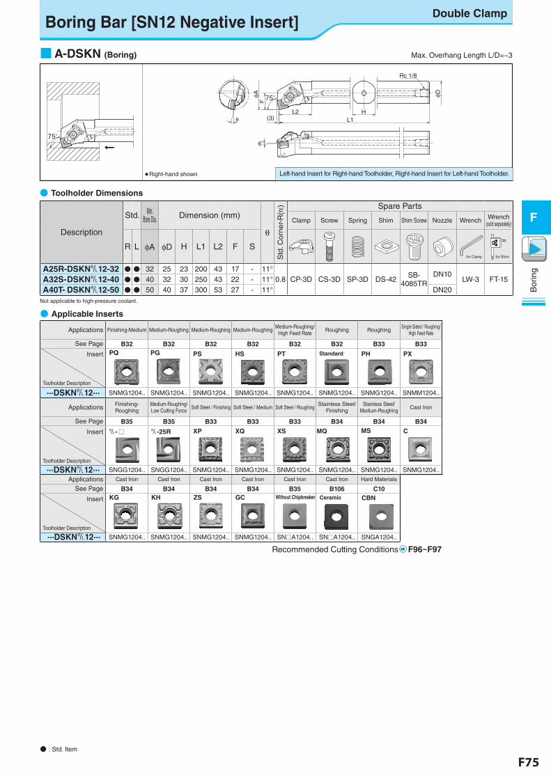
F74 F75
Bor
ing
F
Bor
ing
F
Boring Bar [SN12 Negative Insert]Double Clamp
● Applicable Inserts
Applications Finishing-Medium Medium-Roughing Medium-Roughing Medium-RoughingMedium-Roughing/
High Feed RateRoughing Roughing
Single Sided / Roughing/High Feed Rate
See Page B32 B32 B32 B32 B32 B32 B33 B33
Insert
Toolholder Description
PG
...DSKN&12... SNMG1204.. SNMG1204.. SNMG1204.. SNMG1204.. SNMG1204.. SNMG1204.. SNMG1204.. SNMM1204..
Applications Finishing-Roughing
Medium-Roughing/Low Cutting Force
Soft Steel / Finishing Soft Steel / Medium Soft Steel / RoughingStainless Steel/
FinishingStainless Steel/
Medium-RoughingCast Iron
See Page B35 B35 B33 B33 B33 B34 B34 B34
Insert
Toolholder Description
...DSKN&12... SNGG1204.. SNGG1204.. SNMG1204.. SNMG1204.. SNMG1204.. SNMG1204.. SNMG1204.. SNMG1204.. Applications Cast Iron Cast Iron Cast Iron Cast Iron Cast Iron Cast Iron Hard Materials
See Page B34 B34 B34 B34 B35 B106 C10
Insert
Toolholder Description
...DSKN&12... SNMG1204.. SNMG1204.. SNMG1204.. SNMG1204.. SN□A1204.. SN□A1204.. SNGA1204..
Recommended Cutting Conditions F96~F97
PQ PS HS PT Standard
&- □ &-25R XSXQXP
GC Without Chipbreaker
C
Ceramic CBN
MS
PH PX
MQ
ZSKG KH
Left-hand Insert for Right-hand Toolholder, Right-hand Insert for Left-hand Toolholder.● Right-hand shown
■ A-DSKN (Boring) Max. Overhang Length L/D=~3
Description
Std. Min. Bore Dia. Dimension (mm)
θ
Std
. Cor
ner-
R(rε) Spare Parts
Clamp Screw Spring Shim Shim Screw Nozzle Wrench Wrench(sold separately)
R L φA φD H L1 L2 F S
A25R-DSKN&12-32 ● ● 32 25 23 200 43 17 - 11°0.8 CP-3D CS-3D SP-3D DS-42 SB-
4085TRDN10
LW-3 FT-15A32S- DSKN&12-40 ● ● 40 32 30 250 43 22 - 11°A40T- DSKN&12-50 ● ● 50 40 37 300 53 27 - 11° DN20
Not applicable to high-pressure coolant.
● Toolholder Dimensions
75°
75°
6゜
FφA
θL2 H
L1
φD
Rc 1/8
(3)
for Clamp for Shim
● : Std. Item
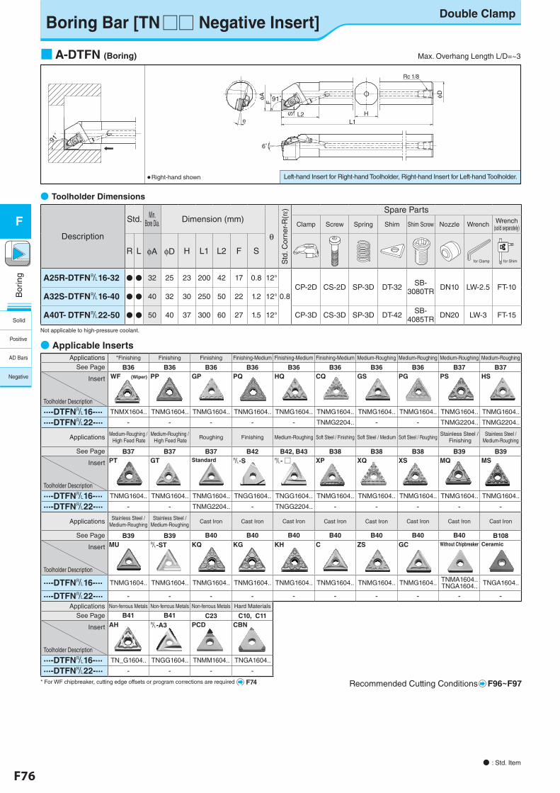
F76 F77
Bor
ing
F
Bor
ing
F
Applications *Finishing Finishing Finishing Finishing-Medium Finishing-Medium Finishing-Medium Medium-Roughing Medium-Roughing Medium-Roughing Medium-Roughing
See Page B36 B36 B36 B36 B36 B36 B36 B36 B37 B37
Insert
Toolholder Description
WF (Wiper) PP GP PQ HQ CQ GS PG PS HS
...-DTFN&16-... TNMX1604.. TNMG1604.. TNMG1604.. TNMG1604.. TNMG1604.. TNMG1604.. TNMG1604.. TNMG1604.. TNMG1604.. TNMG1604..
...-DTFN&22-... - - - - - TNMG2204.. - - TNMG2204.. TNMG2204..
Applications Medium-Roughing / High Feed Rate
Medium-Roughing / High Feed Rate
Roughing Finishing Medium-Roughing Soft Steel / Finishing Soft Steel / Medium Soft Steel / RoughingStainless Steel /
FinishingStainless Steel /
Medium-Roughing
See Page B37 B37 B37 B42 B42, B43 B38 B38 B38 B39 B39
Insert
Toolholder Description
PT GT Standard &-S &- □ XP XQ XS MQ MS
...-DTFN&16-... TNMG1604.. TNMG1604.. TNMG1604.. TNGG1604.. TNGG1604.. TNMG1604.. TNMG1604.. TNMG1604.. TNMG1604.. TNMG1604..
...-DTFN&22-... - - TNMG2204.. - TNGG2204.. - - - - -
Applications Stainless Steel /Medium-Roughing
Stainless Steel /Medium-Roughing
Cast Iron Cast Iron Cast Iron Cast Iron Cast Iron Cast Iron Cast Iron Cast Iron
See Page B39 B39 B40 B40 B40 B40 B40 B40 B40 B108
Insert
Toolholder Description
MU &-ST KQ KG KH C ZS GC Without Chipbreaker Ceramic
...-DTFN&16-... TNMG1604.. TNMG1604.. TNMG1604.. TNMG1604.. TNMG1604.. TNMG1604.. TNMG1604.. TNMG1604.. TNMA1604.. TNGA1604.. TNGA1604..
...-DTFN&22-... - - - - - - - - - -Applications Non-ferrous Metals Non-ferrous Metals Non-ferrous Metals Hard Materials
See Page B41 B41 C23 C10, C11
Insert
Toolholder Description
AH &-A3 PCD CBN
...-DTFN&16-... TN_G1604.. TNGG1604.. TNMM1604.. TNGA1604..
...-DTFN&22-... - - - -
Recommended Cutting Conditions F96~F97
● Applicable Inserts
Left-hand Insert for Right-hand Toolholder, Right-hand Insert for Left-hand Toolholder.● Right-hand shown
Boring Bar [TN□□ Negative Insert]Double Clamp
■ A-DTFN (Boring) Max. Overhang Length L/D=~3
Description
Std. Min. Bore Dia. Dimension (mm)
θ
Std
. Cor
ner-
R(rε) Spare Parts
Clamp Screw Spring Shim Shim Screw Nozzle Wrench Wrench(sold separately)
R L φA φD H L1 L2 F S
A25R-DTFN&16-32 ● ● 32 25 23 200 42 17 0.8 12°
0.8CP-2D CS-2D SP-3D DT-32 SB-
3080TR DN10 LW-2.5 FT-10A32S- DTFN&16-40 ● ● 40 32 30 250 50 22 1.2 12°
A40T- DTFN&22-50 ● ● 50 40 37 300 60 27 1.5 12° CP-3D CS-3D SP-3D DT-42 SB-4085TR DN20 LW-3 FT-15
Not applicable to high-pressure coolant.
● Toolholder Dimensions
91゚
91゚
Rc 1/8
φD
L2S
φA
θ
F
HL1
6゜
91゚
for Clamp for Shim
● : Std. Item
* For WF chipbreaker, cutting edge offsets or program corrections are required F74
Solid
Positive
AD Bars
Negative
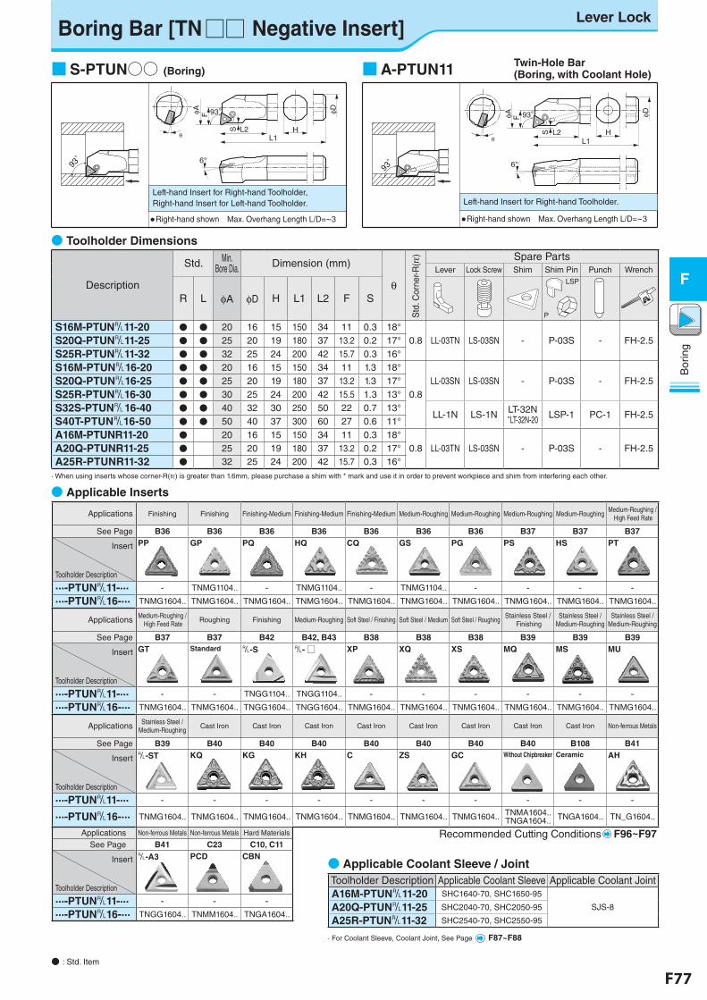
F76 F77
Bor
ing
F
Bor
ing
F
Applications Finishing Finishing Finishing-Medium Finishing-Medium Finishing-Medium Medium-Roughing Medium-Roughing Medium-Roughing Medium-RoughingMedium-Roughing /
High Feed Rate
See Page B36 B36 B36 B36 B36 B36 B36 B37 B37 B37
Insert
Toolholder Description
PP GP PQ HQ CQ GS PG PS HS PT
...-PTUN&11-... - TNMG1104.. - TNMG1104.. - TNMG1104.. - - - -
...-PTUN&16-... TNMG1604.. TNMG1604.. TNMG1604.. TNMG1604.. TNMG1604.. TNMG1604.. TNMG1604.. TNMG1604.. TNMG1604.. TNMG1604..
Applications Medium-Roughing / High Feed Rate
Roughing Finishing Medium-Roughing Soft Steel / Finishing Soft Steel / Medium Soft Steel / RoughingStainless Steel /
FinishingStainless Steel /
Medium-RoughingStainless Steel /
Medium-Roughing
See Page B37 B37 B42 B42, B43 B38 B38 B38 B39 B39 B39
Insert
Toolholder Description
GT Standard &-S &- □ XP XQ XS MQ MS MU
...-PTUN&11-... - - TNGG1104.. TNGG1104.. - - - - - -
...-PTUN&16-... TNMG1604.. TNMG1604.. TNGG1604.. TNGG1604.. TNMG1604.. TNMG1604.. TNMG1604.. TNMG1604.. TNMG1604.. TNMG1604..
Applications Stainless Steel /Medium-Roughing
Cast Iron Cast Iron Cast Iron Cast Iron Cast Iron Cast Iron Cast Iron Cast Iron Non-ferrous Metals
See Page B39 B40 B40 B40 B40 B40 B40 B40 B108 B41
Insert
Toolholder Description
&-ST KQ KG KH C ZS GC Without Chipbreaker Ceramic AH
...-PTUN&11-... - - - - - - - - - -
...-PTUN&16-... TNMG1604.. TNMG1604.. TNMG1604.. TNMG1604.. TNMG1604.. TNMG1604.. TNMG1604.. TNMA1604.. TNGA1604.. TNGA1604.. TN_G1604..
Applications Non-ferrous Metals Non-ferrous Metals Hard Materials Recommended Cutting Conditions F96~F97See Page B41 C23 C10, C11
Insert
Toolholder Description
&-A3 PCD CBN
...-PTUN&11-... - - -
...-PTUN&16-... TNGG1604.. TNMM1604.. TNGA1604..
Boring Bar [TN□□ Negative Insert]Lever Lock
6°
θ
φA
L2L1
F
S H
φD93°
■ S-PTUN○○ (Boring)
● Right-hand shown Max. Overhang Length L/D=~3
Left-hand Insert for Right-hand Toolholder,Right-hand Insert for Left-hand Toolholder.
93゚
93゚
6°
φA
θL2
F
S
L1
φD
H
93°
■ A-PTUN11
● Right-hand shown Max. Overhang Length L/D=~3
Left-hand Insert for Right-hand Toolholder.
93゚
Twin-Hole Bar(Boring, with Coolant Hole)
● Toolholder Dimensions
Description
Std. Min. Bore Dia. Dimension (mm)
θ
Std
. Cor
ner-R
(rε) Spare Parts
Lever Lock Screw Shim Shim Pin Punch Wrench
R L φA φD H L1 L2 F S
LSP
P
S16M-PTUN&11-20 ● ● 20 16 15 150 34 11 0.3 18°
S20Q-PTUN&11-25 ● ● 25 20 19 180 37 13.2 0.2 17° 0.8 LL-03TN LS-03SN - P-03S - FH-2.5
S25R-PTUN&11-32 ● ● 32 25 24 200 42 15.7 0.3 16°
S16M-PTUN&16-20 ● ● 20 16 15 150 34 11 1.3 18°
0.8LL-03SN LS-03SN - P-03S - FH-2.5S20Q-PTUN&16-25 ● ● 25 20 19 180 37 13.2 1.3 17°
S25R-PTUN&16-30 ● ● 30 25 24 200 42 15.5 1.3 13°
S32S-PTUN&16-40 ● ● 40 32 30 250 50 22 0.7 13°LL-1N LS-1N LT-32N
*LT-32N-20 LSP-1 PC-1 FH-2.5S40T-PTUN&16-50 ● ● 50 40 37 300 60 27 0.6 11°
A16M-PTUNR11-20 ● 20 16 15 150 34 11 0.3 18°
A20Q-PTUNR11-25 ● 25 20 19 180 37 13.2 0.2 17° 0.8 LL-03TN LS-03SN - P-03S - FH-2.5A25R-PTUNR11-32 ● 32 25 24 200 42 15.7 0.3 16°
· When using inserts whose corner-R(rε) is greater than 1.6mm, please purchase a shim with * mark and use it in order to prevent workpiece and shim from interfering each other.
● Applicable Inserts
Toolholder Description Applicable Coolant Sleeve Applicable Coolant JointA16M-PTUN&11-20 SHC1640-70, SHC1650-95
SJS-8A20Q-PTUN&11-25 SHC2040-70, SHC2050-95
A25R-PTUN&11-32 SHC2540-70, SHC2550-95
● Applicable Coolant Sleeve / Joint
· For Coolant Sleeve, Coolant Joint, See Page F87~F88
● : Std. Item
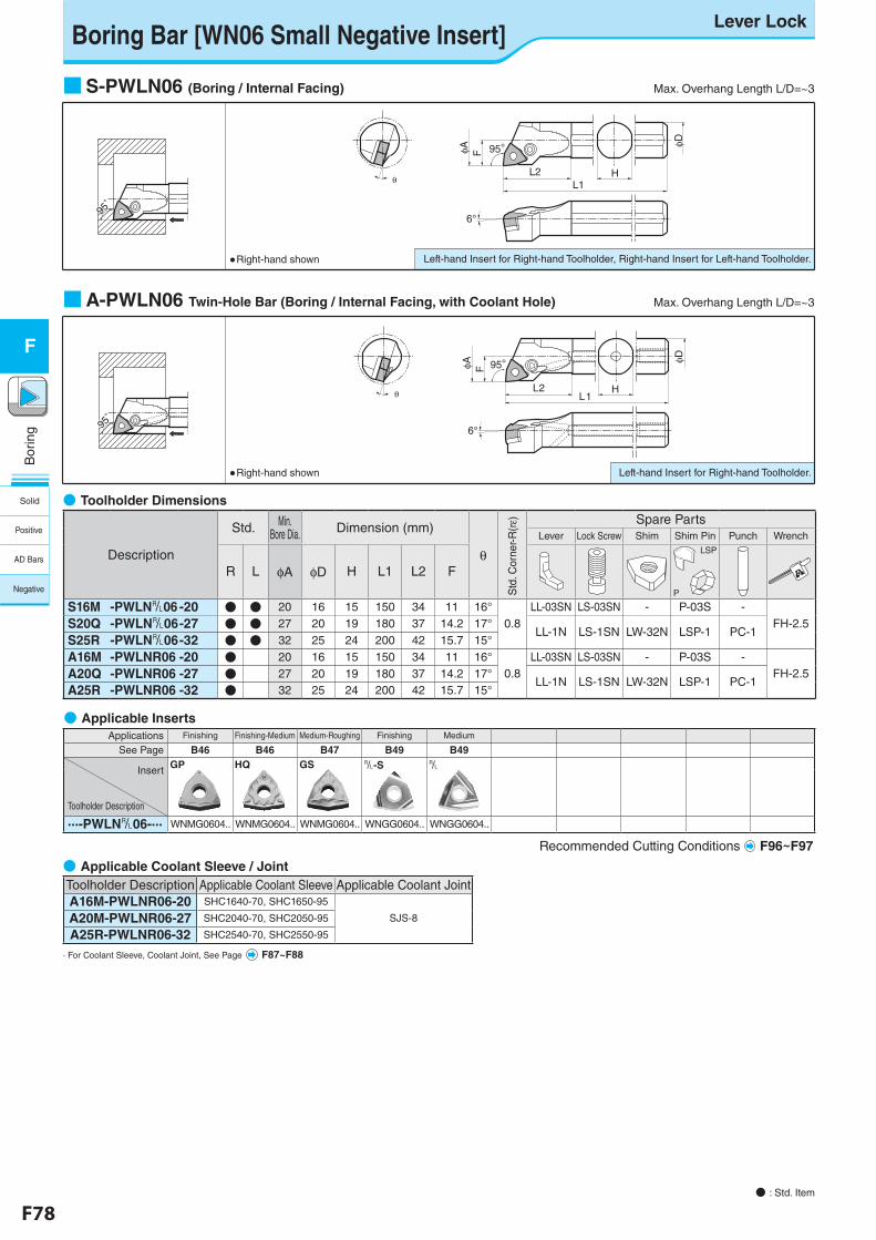
F78 F79
Bor
ing
F
Bor
ing
F
Left-hand Insert for Right-hand Toolholder.
Left-hand Insert for Right-hand Toolholder, Right-hand Insert for Left-hand Toolholder.
Boring Bar [WN06 Small Negative Insert]Lever Lock
● : Std. Item
6°
θ
φA F
2L1L
H
φD95°
θL2
6°
L1
φA F
H
φD95°
95゚
95゚
■ S-PWLN06 (Boring / Internal Facing) Max. Overhang Length L/D=~3
95゚
95゚
■ A-PWLN06 Twin-Hole Bar (Boring / Internal Facing, with Coolant Hole) Max. Overhang Length L/D=~3
● Right-hand shown
● Right-hand shown
● Applicable Coolant Sleeve / JointToolholder Description Applicable Coolant Sleeve Applicable Coolant JointA16M-PWLNR06-20 SHC1640-70, SHC1650-95
SJS-8A20M-PWLNR06-27 SHC2040-70, SHC2050-95
A25R-PWLNR06-32 SHC2540-70, SHC2550-95
· For Coolant Sleeve, Coolant Joint, See Page F87~F88
● Toolholder Dimensions
Description
Std. Min. Bore Dia. Dimension (mm)
θ
Std
. Cor
ner-R
(rε) Spare Parts
Lever Lock Screw Shim Shim Pin Punch Wrench
R L φA φD H L1 L2 F
LSP
P
S16M -PWLN&06 -20 ● ● 20 16 15 150 34 11 16°0.8
LL-03SN LS-03SN - P-03S -FH-2.5S20Q -PWLN&06-27 ● ● 27 20 19 180 37 14.2 17°
LL-1N LS-1SN LW-32N LSP-1 PC-1S25R -PWLN&06-32 ● ● 32 25 24 200 42 15.7 15°
A16M -PWLNR06 -20 ● 20 16 15 150 34 11 16°0.8
LL-03SN LS-03SN - P-03S -FH-2.5A20Q -PWLNR06 -27 ● 27 20 19 180 37 14.2 17°
LL-1N LS-1SN LW-32N LSP-1 PC-1A25R -PWLNR06 -32 ● 32 25 24 200 42 15.7 15°
● Applicable InsertsApplications Finishing Finishing-Medium Medium-Roughing Finishing Medium
See Page B46 B46 B47 B49 B49
Insert
Toolholder Description
GP HQ GS &-S &
...-PWLN&06-... WNMG0604.. WNMG0604.. WNMG0604.. WNGG0604.. WNGG0604..
Recommended Cutting Conditions F96~F97
Solid
Positive
AD Bars
Negative
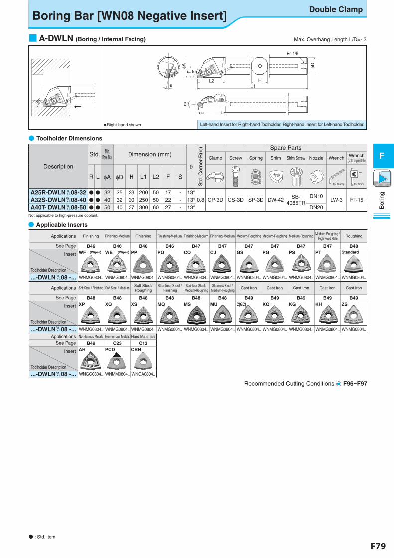
F78 F79
Bor
ing
F
Bor
ing
F
Applications Finishing Finishing-Medium Finishing Finishing-Medium Finishing-Medium Finishing-Medium Medium-Roughing Medium-Roughing Medium-RoughingMedium-Roughing /
High Feed RateRoughing
See Page B46 B46 B46 B46 B47 B47 B47 B47 B47 B47 B48
Insert
Toolholder Description
WF (Wiper) WE (Wiper) PP PQ CQ CJ GS PG PS PT Standard
...-DWLN&08 -... WNMG0804.. WNMG0804.. WNMG0804.. WNMG0804.. WNMG0804.. WNMG0804.. WNMG0804.. WNMG0804.. WNMG0804.. WNMG0804.. WNMG0804..
Applications Soft Steel / Finishing Soft Steel / MediumSoft Steel/Roughing
Stainless Steel / Finishing
Stainless Steel / Medium-Roughing
Stainless Steel / Medium-Roughing
Cast Iron Cast Iron Cast Iron Cast Iron Cast Iron
See Page B48 B48 B48 B48 B48 B48 B49 B49 B49 B49 B49
Insert
Toolholder Description
XP XQ XS MQ MS MU C(GC) KQ KG KH ZS
...-DWLN&08 -... WNMG0804.. WNMG0804.. WNMG0804.. WNMG0804.. WNMG0804.. WNMG0804.. WNMG0804.. WNMG0804.. WNMG0804.. WNMG0804.. WNMG0804..
Applications Non-ferrous Metals Non-ferrous Metals Hard Materials
See Page B49 C23 C13
Insert
Toolholder Description
AH PCD CBN
...-DWLN&08 -... WNGG0804.. WNMM0804.. WNGA0804..
Recommended Cutting Conditions F96~F97
ボーリングバー[WN08ネガチップ用] レバーロック方式Boring Bar [WN08 Negative Insert]
Double Clamp
Left-hand Insert for Right-hand Toolholder, Right-hand Insert for Left-hand Toolholder.● Right-hand shown
■ A-DWLN (Boring / Internal Facing) Max. Overhang Length L/D=~3
Description
Std. Min. Bore Dia. Dimension (mm)
θ
Std
. Cor
ner-
R(rε) Spare Parts
Clamp Screw Spring Shim Shim Screw Nozzle Wrench Wrench(sold separately)
R L φA φD H L1 L2 F S
A25R-DWLN&08-32 ● ● 32 25 23 200 50 17 - 13°0.8 CP-3D CS-3D SP-3D DW-42 SB-
4085TRDN10
LW-3 FT-15A32S- DWLN&08-40 ● ● 40 32 30 250 50 22 - 13°A40T- DWLN&08-50 ● ● 50 40 37 300 60 27 - 13° DN20
Not applicable to high-pressure coolant.
● Toolholder Dimensions
95゚
95゚
Rc 1/8
φ D
HL1
L2
Fφ A
θ
6゜
95゚
for Clamp for Shim
● Applicable Inserts
● : Std. Item
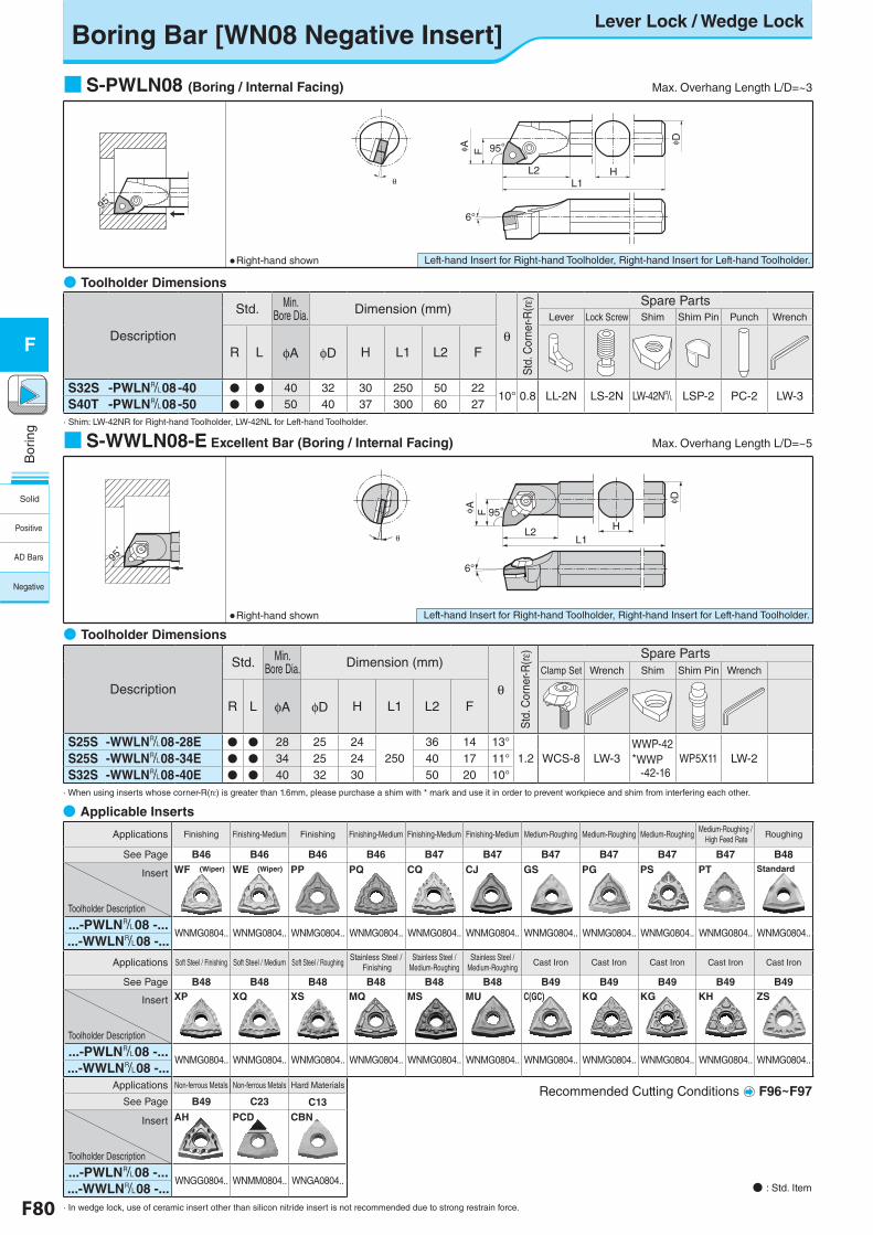
F80 F81
Bor
ing
F
Bor
ing
F
Applications Finishing Finishing-Medium Finishing Finishing-Medium Finishing-Medium Finishing-Medium Medium-Roughing Medium-Roughing Medium-RoughingMedium-Roughing /
High Feed RateRoughing
See Page B46 B46 B46 B46 B47 B47 B47 B47 B47 B47 B48
Insert
Toolholder Description
WF (Wiper) WE (Wiper) PP PQ CQ CJ GS PG PS PT Standard
...-PWLN&08 -...WNMG0804.. WNMG0804.. WNMG0804.. WNMG0804.. WNMG0804.. WNMG0804.. WNMG0804.. WNMG0804.. WNMG0804.. WNMG0804.. WNMG0804..
...-WWLN&08 -...
Applications Soft Steel / Finishing Soft Steel / Medium Soft Steel / RoughingStainless Steel /
FinishingStainless Steel /
Medium-RoughingStainless Steel /
Medium-RoughingCast Iron Cast Iron Cast Iron Cast Iron Cast Iron
See Page B48 B48 B48 B48 B48 B48 B49 B49 B49 B49 B49
Insert
Toolholder Description
XP XQ XS MQ MS MU C(GC) KQ KG KH ZS
...-PWLN&08 -...WNMG0804.. WNMG0804.. WNMG0804.. WNMG0804.. WNMG0804.. WNMG0804.. WNMG0804.. WNMG0804.. WNMG0804.. WNMG0804.. WNMG0804..
...-WWLN&08 -...Applications Non-ferrous Metals Non-ferrous Metals Hard Materials
See Page B49 C23 C13
Insert
Toolholder Description
AH PCD CBN
...-PWLN&08 -...WNGG0804.. WNMM0804.. WNGA0804..
...-WWLN&08 -...· In wedge lock, use of ceramic insert other than silicon nitride insert is not recommended due to strong restrain force.
Boring Bar [WN08 Negative Insert]Lever Lock / Wedge Lock
95゚
95゚
■ S-PWLN08 (Boring / Internal Facing) Max. Overhang Length L/D=~3
Left-hand Insert for Right-hand Toolholder, Right-hand Insert for Left-hand Toolholder.
θL2
6°
L1
φ A F
H
φ D
95°
● Right-hand shown
● : Std. Item
● Applicable Inserts
● Toolholder Dimensions
Description
Std. Min.Bore Dia. Dimension (mm)
θ
Std
. Cor
ner-R
(rε) Spare Parts
Lever Lock Screw Shim Shim Pin Punch Wrench
R L φA φD H L1 L2 F
S32S -PWLN&08-40 ● ● 40 32 30 250 50 2210° 0.8 LL-2N LS-2N LW-42N& LSP-2 PC-2 LW-3
S40T -PWLN&08-50 ● ● 50 40 37 300 60 27· Shim: LW-42NR for Right-hand Toolholder, LW-42NL for Left-hand Toolholder.
● Toolholder Dimensions
Description
Std. Min.Bore Dia. Dimension (mm)
θ
Std
. Cor
ner-R
(rε) Spare Parts
Clamp Set Wrench Shim Shim Pin Wrench
R L φA φD H L1 L2 F
S25S -WWLN&08-28E ● ● 28 25 24250
36 14 13°1.2 WCS-8 LW-3
WWP-42*WWP -42-16
WP5X11 LW-2S25S -WWLN&08-34E ● ● 34 25 24 40 17 11°S32S -WWLN&08-40E ● ● 40 32 30 50 20 10°
· When using inserts whose corner-R(rε) is greater than 1.6mm, please purchase a shim with * mark and use it in order to prevent workpiece and shim from interfering each other.
Left-hand Insert for Right-hand Toolholder, Right-hand Insert for Left-hand Toolholder.
95゚
95゚
6°
L2
Fφ A
φ D
L1H
95°
θ
● Right-hand shown
Recommended Cutting Conditions F96~F97
Solid
Positive
AD Bars
Negative
■ S-WWLN08-E Excellent Bar (Boring / Internal Facing) Max. Overhang Length L/D=~5
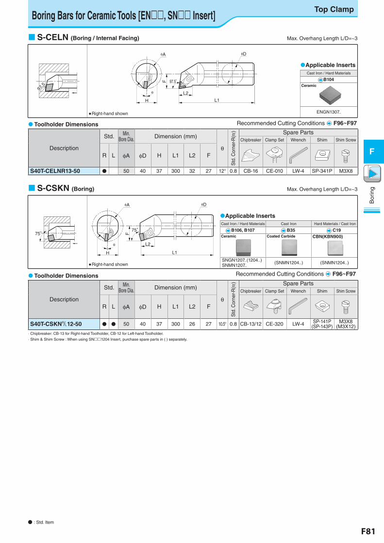
F80 F81
Bor
ing
F
Bor
ing
F
● : Std. Item
Applicable InsertsCast Iron / Hard Materials
B104Ceramic
ENGN1307..
97.5゚
97.5゚
H L1
L2θ
F 97.5°
φA φD
Boring Bars for Ceramic Tools [EN, SN Insert]Top Clamp
S-CELN (Boring / Internal Facing) Max. Overhang Length L/D=~3
● Right-hand shown
Toolholder Dimensions
Description
Std. Min. Bore Dia. Dimension (mm)
θ
Std
. Cor
ner-R
(rε) Spare Parts
Chipbreaker Clamp Set Wrench Shim Shim Screw
R L φA φD H L1 L2 F
S40T-CELNR13-50 ● 50 40 37 300 32 27 12° 0.8 CB-16 CE-010 LW-4 SP-341P M3X8
Recommended Cutting Conditions F96~F97
S-CSKN (Boring) Max. Overhang Length L/D=~3
Applicable InsertsCast Iron / Hard Materials Cast Iron Hard Materials / Cast Iron
B106, B107 B35 C19Ceramic Coated Carbide CBN(KBN900)
SNGN1207..(1204..)SNMN1207.. (SNMN1204..) (SNMN1204..)
75°
H
F
θ
75°
φA
L2
L1
φD
● Right-hand shown
Recommended Cutting Conditions F96~F97 Toolholder Dimensions
Description
Std. Min. Bore Dia. Dimension (mm)
θ
Std
. Cor
ner-R
(rε) Spare Parts
Chipbreaker Clamp Set Wrench Shim Shim Screw
R L φA φD H L1 L2 F
S40T-CSKN&12-50 ● ● 50 40 37 300 26 27 10.5° 0.8 CB-13/12 CE-320 LW-4 SP-141P(SP-143P)
M3X8(M3X12)
· Chipbreaker: CB-13 for Right-hand Toolholder, CB-12 for Left-hand Toolholder.
· Shim & Shim Screw : When using SN1204 Insert, purchase spare parts in ( ) separately.
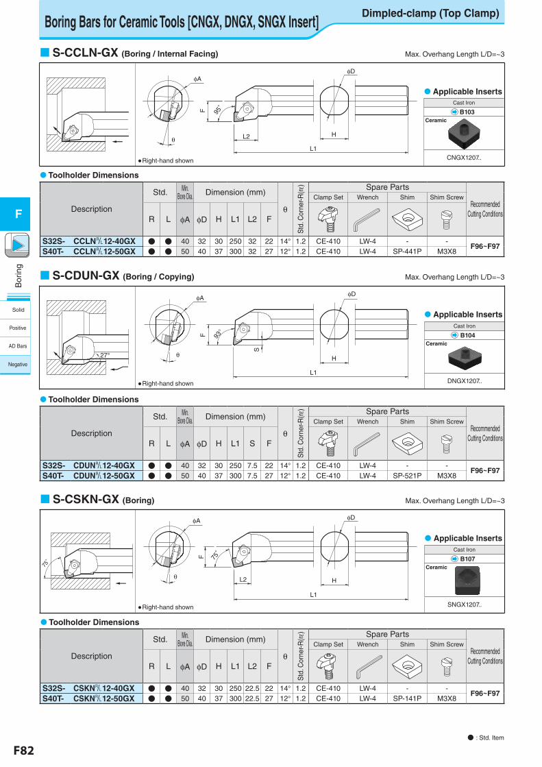
F82 F83
Bor
ing
F
Bor
ing
F
Cast Iron
B104Ceramic
DNGX1207..
Boring Bars for Ceramic Tools [CNGX, DNGX, SNGX Insert]Dimpled-clamp (Top Clamp)
● : Std. Item
Applicable InsertsCast Iron
B103Ceramic
CNGX1207..
φAφD
θ
F 95°
L2
L1
H
S-CCLN-GX (Boring / Internal Facing) Max. Overhang Length L/D=~3
● Right-hand shown
S-CDUN-GX (Boring / Copying) Max. Overhang Length L/D=~3
27°
φAφD
θ
F
S
93°
L1
H
● Right-hand shown
Applicable Inserts
Toolholder Dimensions
Description
Std. Min. Bore Dia. Dimension (mm)
θ
Std
. Cor
ner-R
(rε) Spare Parts
Recommended Cutting Conditions
Clamp Set Wrench Shim Shim Screw
R L φA φD H L1 L2 F
S32S- CCLN&12-40GX ● ● 40 32 30 250 32 22 14° 1.2 CE-410 LW-4 - -F96~F97
S40T- CCLN&12-50GX ● ● 50 40 37 300 32 27 12° 1.2 CE-410 LW-4 SP-441P M3X8
Toolholder Dimensions
Description
Std. Min. Bore Dia. Dimension (mm)
θ
Std
. Cor
ner-R
(rε) Spare Parts
Recommended Cutting Conditions
Clamp Set Wrench Shim Shim Screw
R L φA φD H L1 S F
S32S- CDUN&12-40GX ● ● 40 32 30 250 7.5 22 14° 1.2 CE-410 LW-4 - -F96~F97
S40T- CDUN&12-50GX ● ● 50 40 37 300 7.5 27 12° 1.2 CE-410 LW-4 SP-521P M3X8
S-CSKN-GX (Boring) Max. Overhang Length L/D=~3
Applicable InsertsCast Iron
B107Ceramic
SNGX1207..
φA φD
θ
F 75°
L2
L1
H
75°
● Right-hand shown
Toolholder Dimensions
Description
Std. Min. Bore Dia. Dimension (mm)
θ
Std
. Cor
ner-R
(re) Spare Parts
Recommended Cutting Conditions
Clamp Set Wrench Shim Shim Screw
R L φA φD H L1 L2 F
S32S- CSKN&12-40GX ● ● 40 32 30 250 22.5 22 14° 1.2 CE-410 LW-4 - -F96~F97
S40T- CSKN&12-50GX ● ● 50 40 37 300 22.5 27 12° 1.2 CE-410 LW-4 SP-141P M3X8
Solid
Positive
AD Bars
Negative
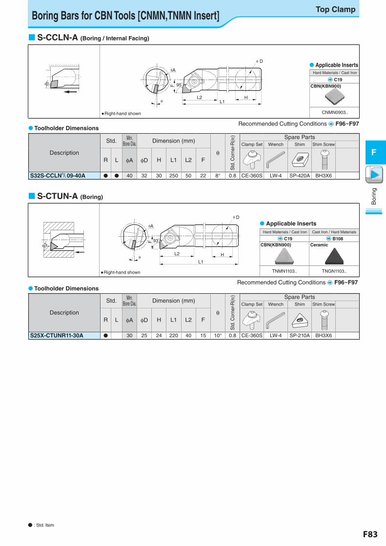
F82 F83
Bor
ing
F
Bor
ing
F
● : Std. Item
Boring Bars for CBN Tools [CNMN,TNMN Insert]
S-CCLN-A (Boring / Internal Facing)
Toolholder Dimensions
95゚
95゚
θL2
L1H
φA
F
Dφ
95゚
● Right-hand shown
Applicable Inserts Hard Materials / Cast Iron
C19CBN(KBN900)
CNMN0903..
S-CTUN-A (Boring)
Toolholder Dimensions
Recommended Cutting Conditions F96~F97
Recommended Cutting Conditions F96~F97
Description
Std. Min. Bore Dia. Dimension (mm)
θ
Std
. Cor
ner-R
(rε) Spare Parts
Clamp Set Wrench Shim Shim Screw
R L φA φD H L1 L2 F
S32S-CCLN&09-40A ● ● 40 32 30 250 50 22 8° 0.8 CE-360S LW-4 SP-420A BH3X6
93゚
93゚
φA
F
θL2
L1
H
Dφ
93゚
● Right-hand shown
Applicable Inserts Hard Materials / Cast Iron Cast Iron / Hard Materials
C19 B108CBN(KBN900) Ceramic
TNMN1103.. TNGN1103..
Description
Std. Min. Bore Dia. Dimension (mm)
θ
Std
. Cor
ner-R
(rε) Spare Parts
Clamp Set Wrench Shim Shim Screw
R L φA φD H L1 L2 F
S25X-CTUNR11-30A ● 30 25 24 220 40 15 10° 0.8 CE-360S LW-4 SP-210A BH3X6
Top Clamp
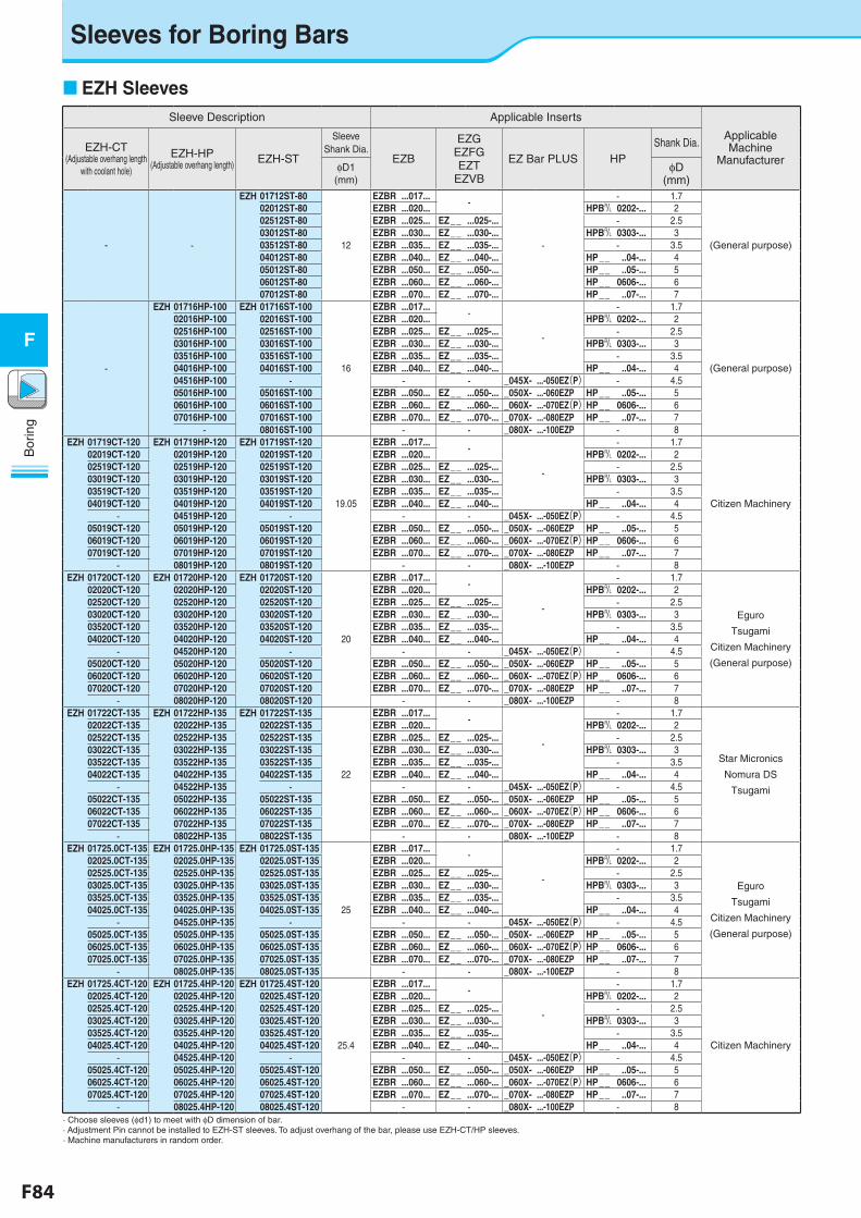
F84 F85
Bor
ing
F
Bor
ing
F
Sleeves for Boring Bars
EZH SleevesSleeve Description Applicable Inserts
Applicable Machine
ManufacturerEZH-CT
(Adjustable overhang length with coolant hole)
EZH-HP(Adjustable overhang length) EZH-ST
Sleeve Shank Dia.
EZB
EZG EZFG EZT
EZVB
EZ Bar PLUS HP Shank Dia.
φD1(mm)
φD(mm)
- -
EZH 01712ST-80
12
EZBR ...017... -
-
- 1.7
(General purpose)
02012ST-80 EZBR ...020... HPB& 0202-... 202512ST-80 EZBR ...025... EZ__ ...025-... - 2.503012ST-80 EZBR ...030... EZ__ ...030-... HPB& 0303-... 303512ST-80 EZBR ...035... EZ__ ...035-... - 3.504012ST-80 EZBR ...040... EZ__ ...040-... HP__ ..04-... 405012ST-80 EZBR ...050... EZ__ ...050-... HP__ ..05-... 506012ST-80 EZBR ...060... EZ__ ...060-... HP__ 0606-... 607012ST-80 EZBR ...070... EZ__ ...070-... HP__ ..07-... 7
-
EZH 01716HP-100 EZH 01716ST-100
16
EZBR ...017... -
-
- 1.7
(General purpose)
02016HP-100 02016ST-100 EZBR ...020... HPB& 0202-... 202516HP-100 02516ST-100 EZBR ...025... EZ__ ...025-... - 2.503016HP-100 03016ST-100 EZBR ...030... EZ__ ...030-... HPB& 0303-... 303516HP-100 03516ST-100 EZBR ...035... EZ__ ...035-... - 3.504016HP-100 04016ST-100 EZBR ...040... EZ__ ...040-... HP__ ..04-... 404516HP-100 - - - _045X- ...-050EZ(P) - 4.505016HP-100 05016ST-100 EZBR ...050... EZ__ ...050-... _050X- ...-060EZP HP__ ..05-... 506016HP-100 06016ST-100 EZBR ...060... EZ__ ...060-... _060X- ...-070EZ(P)HP__ 0606-... 607016HP-100 07016ST-100 EZBR ...070... EZ__ ...070-... _070X- ...-080EZP HP__ ..07-... 7
- 08016ST-100 - - _080X- ...-100EZP - 8EZH 01719CT-120 EZH 01719HP-120 EZH 01719ST-120
19.05
EZBR ...017... -
-
- 1.7
Citizen Machinery
02019CT-120 02019HP-120 02019ST-120 EZBR ...020... HPB& 0202-... 202519CT-120 02519HP-120 02519ST-120 EZBR ...025... EZ__ ...025-... - 2.503019CT-120 03019HP-120 03019ST-120 EZBR ...030... EZ__ ...030-... HPB& 0303-... 303519CT-120 03519HP-120 03519ST-120 EZBR ...035... EZ__ ...035-... - 3.504019CT-120 04019HP-120 04019ST-120 EZBR ...040... EZ__ ...040-... HP__ ..04-... 4
- 04519HP-120 - - - _045X- ...-050EZ(P) - 4.505019CT-120 05019HP-120 05019ST-120 EZBR ...050... EZ__ ...050-... _050X- ...-060EZP HP__ ..05-... 506019CT-120 06019HP-120 06019ST-120 EZBR ...060... EZ__ ...060-... _060X- ...-070EZ(P)HP__ 0606-... 607019CT-120 07019HP-120 07019ST-120 EZBR ...070... EZ__ ...070-... _070X- ...-080EZP HP__ ..07-... 7
- 08019HP-120 08019ST-120 - - _080X- ...-100EZP - 8EZH 01720CT-120 EZH 01720HP-120 EZH 01720ST-120
20
EZBR ...017... -
-
- 1.7
Eguro
Tsugami
Citizen Machinery
(General purpose)
02020CT-120 02020HP-120 02020ST-120 EZBR ...020... HPB& 0202-... 202520CT-120 02520HP-120 02520ST-120 EZBR ...025... EZ__ ...025-... - 2.503020CT-120 03020HP-120 03020ST-120 EZBR ...030... EZ__ ...030-... HPB& 0303-... 303520CT-120 03520HP-120 03520ST-120 EZBR ...035... EZ__ ...035-... - 3.504020CT-120 04020HP-120 04020ST-120 EZBR ...040... EZ__ ...040-... HP__ ..04-... 4
- 04520HP-120 - - - _045X- ...-050EZ(P) - 4.505020CT-120 05020HP-120 05020ST-120 EZBR ...050... EZ__ ...050-... _050X- ...-060EZP HP__ ..05-... 506020CT-120 06020HP-120 06020ST-120 EZBR ...060... EZ__ ...060-... _060X- ...-070EZ(P)HP__ 0606-... 607020CT-120 07020HP-120 07020ST-120 EZBR ...070... EZ__ ...070-... _070X- ...-080EZP HP__ ..07-... 7
- 08020HP-120 08020ST-120 - - _080X- ...-100EZP - 8EZH 01722CT-135 EZH 01722HP-135 EZH 01722ST-135
22
EZBR ...017... -
-
- 1.7
Star Micronics
Nomura DS
Tsugami
02022CT-135 02022HP-135 02022ST-135 EZBR ...020... HPB& 0202-... 202522CT-135 02522HP-135 02522ST-135 EZBR ...025... EZ__ ...025-... - 2.503022CT-135 03022HP-135 03022ST-135 EZBR ...030... EZ__ ...030-... HPB& 0303-... 303522CT-135 03522HP-135 03522ST-135 EZBR ...035... EZ__ ...035-... - 3.504022CT-135 04022HP-135 04022ST-135 EZBR ...040... EZ__ ...040-... HP__ ..04-... 4
- 04522HP-135 - - - _045X- ...-050EZ(P) - 4.505022CT-135 05022HP-135 05022ST-135 EZBR ...050... EZ__ ...050-... _050X- ...-060EZP HP__ ..05-... 506022CT-135 06022HP-135 06022ST-135 EZBR ...060... EZ__ ...060-... _060X- ...-070EZ(P)HP__ 0606-... 607022CT-135 07022HP-135 07022ST-135 EZBR ...070... EZ__ ...070-... _070X- ...-080EZP HP__ ..07-... 7
- 08022HP-135 08022ST-135 - - _080X- ...-100EZP - 8EZH 01725.0CT-135 EZH 01725.0HP-135 EZH 01725.0ST-135
25
EZBR ...017... -
-
- 1.7
Eguro
Tsugami
Citizen Machinery
(General purpose)
02025.0CT-135 02025.0HP-135 02025.0ST-135 EZBR ...020... HPB& 0202-... 202525.0CT-135 02525.0HP-135 02525.0ST-135 EZBR ...025... EZ__ ...025-... - 2.503025.0CT-135 03025.0HP-135 03025.0ST-135 EZBR ...030... EZ__ ...030-... HPB& 0303-... 303525.0CT-135 03525.0HP-135 03525.0ST-135 EZBR ...035... EZ__ ...035-... - 3.504025.0CT-135 04025.0HP-135 04025.0ST-135 EZBR ...040... EZ__ ...040-... HP__ ..04-... 4
- 04525.0HP-135 - - - _045X- ...-050EZ(P) - 4.505025.0CT-135 05025.0HP-135 05025.0ST-135 EZBR ...050... EZ__ ...050-... _050X- ...-060EZP HP__ ..05-... 506025.0CT-135 06025.0HP-135 06025.0ST-135 EZBR ...060... EZ__ ...060-... _060X- ...-070EZ(P)HP__ 0606-... 607025.0CT-135 07025.0HP-135 07025.0ST-135 EZBR ...070... EZ__ ...070-... _070X- ...-080EZP HP__ ..07-... 7
- 08025.0HP-135 08025.0ST-135 - - _080X- ...-100EZP - 8EZH 01725.4CT-120 EZH 01725.4HP-120 EZH 01725.4ST-120
25.4
EZBR ...017... -
-
- 1.7
Citizen Machinery
02025.4CT-120 02025.4HP-120 02025.4ST-120 EZBR ...020... HPB& 0202-... 202525.4CT-120 02525.4HP-120 02525.4ST-120 EZBR ...025... EZ__ ...025-... - 2.503025.4CT-120 03025.4HP-120 03025.4ST-120 EZBR ...030... EZ__ ...030-... HPB& 0303-... 303525.4CT-120 03525.4HP-120 03525.4ST-120 EZBR ...035... EZ__ ...035-... - 3.504025.4CT-120 04025.4HP-120 04025.4ST-120 EZBR ...040... EZ__ ...040-... HP__ ..04-... 4
- 04525.4HP-120 - - - _045X- ...-050EZ(P) - 4.505025.4CT-120 05025.4HP-120 05025.4ST-120 EZBR ...050... EZ__ ...050-... _050X- ...-060EZP HP__ ..05-... 506025.4CT-120 06025.4HP-120 06025.4ST-120 EZBR ...060... EZ__ ...060-... _060X- ...-070EZ(P)HP__ 0606-... 607025.4CT-120 07025.4HP-120 07025.4ST-120 EZBR ...070... EZ__ ...070-... _070X- ...-080EZP HP__ ..07-... 7
- 08025.4HP-120 08025.4ST-120 - - _080X- ...-100EZP - 8· Choose sleeves (φd1) to meet with φD dimension of bar.· Adjustment Pin cannot be installed to EZH-ST sleeves. To adjust overhang of the bar, please use EZH-CT/HP sleeves.· Machine manufacturers in random order.
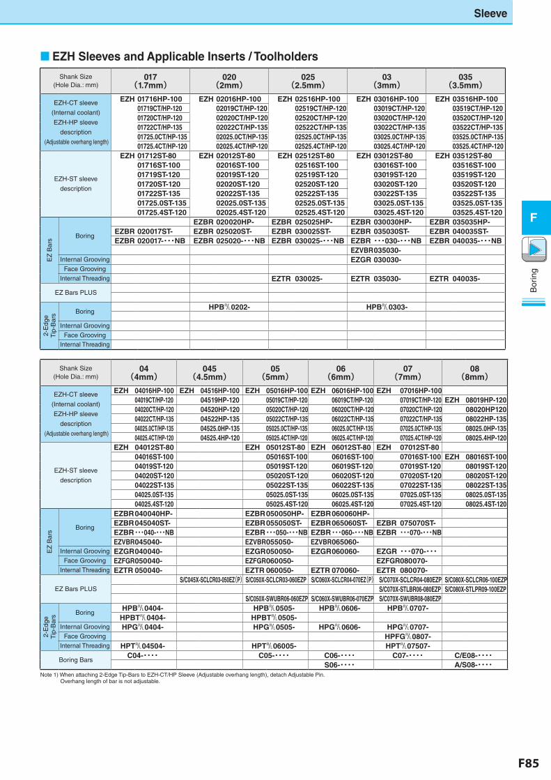
F84 F85
Bor
ing
F
Bor
ing
F
EZH Sleeves and Applicable Inserts / Toolholders
Sleeve
Shank Size(Hole Dia.: mm)
017 (1.7mm)
020 (2mm)
025 (2.5mm)
03 (3mm)
035 (3.5mm)
EZH-CT sleeve
(Internal coolant)
EZH-HP sleeve
description
(Adjustable overhang length)
EZH 01716HP-100 EZH 02016HP-100 EZH 02516HP-100 EZH 03016HP-100 EZH 03516HP-10001719CT/HP-120 02019CT/HP-120 02519CT/HP-120 03019CT/HP-120 03519CT/HP-12001720CT/HP-120 02020CT/HP-120 02520CT/HP-120 03020CT/HP-120 03520CT/HP-12001722CT/HP-135 02022CT/HP-135 02522CT/HP-135 03022CT/HP-135 03522CT/HP-13501725.0CT/HP-135 02025.0CT/HP-135 02525.0CT/HP-135 03025.0CT/HP-135 03525.0CT/HP-13501725.4CT/HP-120 02025.4CT/HP-120 02525.4CT/HP-120 03025.4CT/HP-120 03525.4CT/HP-120
EZH-ST sleeve
description
EZH 01712ST-80 EZH 02012ST-80 EZH 02512ST-80 EZH 03012ST-80 EZH 03512ST-8001716ST-100 02016ST-100 02516ST-100 03016ST-100 03516ST-10001719ST-120 02019ST-120 02519ST-120 03019ST-120 03519ST-12001720ST-120 02020ST-120 02520ST-120 03020ST-120 03520ST-12001722ST-135 02022ST-135 02522ST-135 03022ST-135 03522ST-13501725.0ST-135 02025.0ST-135 02525.0ST-135 03025.0ST-135 03525.0ST-13501725.4ST-120 02025.4ST-120 02525.4ST-120 03025.4ST-120 03525.4ST-120
EZ
Bar
s Boring
EZBR 020020HP- EZBR 025025HP- EZBR 030030HP- EZBR 035035HP-EZBR 020017ST- EZBR 025020ST- EZBR 030025ST- EZBR 035030ST- EZBR 040035ST-EZBR 020017-・・・NB EZBR 025020-・・・NB EZBR 030025-・・・NB EZBR・・・030-・・・NB EZBR 040035-・・・NB
EZVBR035030-Internal Grooving EZGR 030030-
Face Grooving
Internal Threading EZTR 030025- EZTR 035030- EZTR 040035-
EZ Bars PLUS
2-E
dge
Tip
-Bar
s BoringHPB&0202- HPB&0303-
Internal Grooving
Face GroovingInternal Threading
Shank Size(Hole Dia.: mm)
04 (4mm)
045 (4.5mm)
05 (5mm)
06 (6mm)
07(7mm)
08 (8mm)
EZH-CT sleeve
(Internal coolant)
EZH-HP sleeve
description
(Adjustable overhang length)
EZH 04016HP-100 EZH 04516HP-100 EZH 05016HP-100 EZH 06016HP-100 EZH 07016HP-10004019CT/HP-120 04519HP-120 05019CT/HP-120 06019CT/HP-120 07019CT/HP-120 EZH 08019HP-12004020CT/HP-120 04520HP-120 05020CT/HP-120 06020CT/HP-120 07020CT/HP-120 08020HP12004022CT/HP-135 04522HP-135 05022CT/HP-135 06022CT/HP-135 07022CT/HP-135 08022HP-13504025.0CT/HP-135 04525.0HP-135 05025.0CT/HP-135 06025.0CT/HP-135 07025.0CT/HP-135 08025.0HP-13504025.4CT/HP-120 04525.4HP-120 05025.4CT/HP-120 06025.4CT/HP-120 07025.4CT/HP-120 08025.4HP-120
EZH-ST sleeve
description
EZH 04012ST-80 EZH 05012ST-80 EZH 06012ST-80 EZH 07012ST-8004016ST-100 05016ST-100 06016ST-100 07016ST-100 EZH 08016ST-10004019ST-120 05019ST-120 06019ST-120 07019ST-120 08019ST-12004020ST-120 05020ST-120 06020ST-120 07020ST-120 08020ST-12004022ST-135 05022ST-135 06022ST-135 07022ST-135 08022ST-13504025.0ST-135 05025.0ST-135 06025.0ST-135 07025.0ST-135 08025.0ST-13504025.4ST-120 05025.4ST-120 06025.4ST-120 07025.4ST-120 08025.4ST-120
EZ
Bar
s Boring
EZBR040040HP- EZBR050050HP- EZBR060060HP-EZBR045040ST- EZBR055050ST- EZBR065060ST- EZBR 075070ST-EZBR・・・040-・・・NB EZBR・・・050-・・・NB EZBR・・・060-・・・NB EZBR ・・・070-・・・NBEZVBR045040- EZVBR055050- EZVBR065060-
Internal Grooving EZGR040040- EZGR050050- EZGR060060- EZGR ・・・070-・・・Face Grooving EZFGR050040- EZFGR060050- EZFGR080070-
Internal Threading EZTR 050040- EZTR 060050- EZTR 070060- EZTR 080070-
EZ Bars PLUSS/C045X-SCLCR03-050EZ(P) S/C050X-SCLCR03-060EZP S/C060X-SCLCR04-070EZ(P) S/C070X-SCLCR04-080EZP S/C080X-SCLCR06-100EZP
S/C070X-STLBR06-080EZP S/C080X-STLPR09-100EZPS/C050X-SWUBR06-060EZP S/C060X-SWUBR06-070EZP S/C070X-SWUBR08-080EZP
2-E
dge
Tip
-Bar
s BoringHPB&0404- HPB&0505- HPB&0606- HPB&0707-
HPBT&0404- HPBT&0505-Internal Grooving HPG&0404- HPG&0505- HPG&0606- HPG&0707-
Face Grooving HPFG&0807-Internal Threading HPT&04504- HPT&06005- HPT&07507-
Boring BarsC04-・・・・ C05-・・・・ C06-・・・・ C07-・・・・ C/E08-・・・・
S06-・・・・ A/S08-・・・・Note 1) When attaching 2-Edge Tip-Bars to EZH-CT/HP Sleeve (Adjustable overhang length), detach Adjustable Pin. Overhang length of bar is not adjustable.
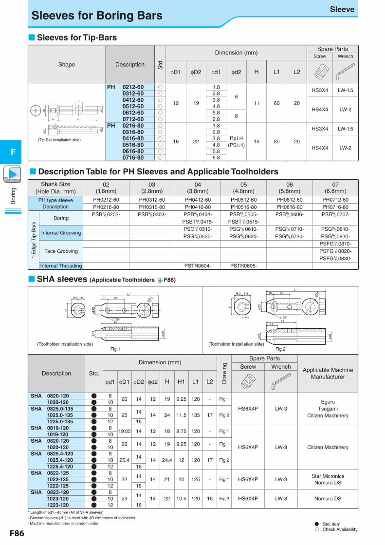
F86 F87
Bor
ing
F
Bor
ing
F
Sleeves for Boring BarsSleeve
H/2
H
L110 25
φD2
φD1
25°
H1
φd1
φd2
45
L1
φD1
φD2
φd2
φd1
25°
H
L2
2510H/2 H1
10
45
Fig.1 Fig.2
Description Std.
Dimension (mm)
Dra
win
g
Spare Parts
Applicable Machine Manufacturer
Screw Wrench
φd1 φD1 φD2 φd2 H H1 L1 L2
SHA 0820-120 ● 820 14 12 19 9.25 120 - Fig.1
HS6X4P LW-3Eguro
TsugamiCitizen Machinery
1020-120 ● 10SHA 0825.0-135 ● 8
2514
14 24 11.5 135 17 Fig.21025.0-135 ● 101225.0-135 ● 12 16
SHA 0819-120 ● 819.05 14 12 18 8.75 120 - Fig.1
HS6X4P LW-3 Citizen Machinery
1019-120 ● 10SHA 0820-120 ● 8
20 14 12 19 9.25 120 - Fig.11020-120 ● 10
SHA 0825.4-120 ● 825.4
1414 24.4 12 120 17 Fig.21025.4-120 ● 10
1225.4-120 ● 12 16SHA 0822-125 ● 8
2214
14 21 10 125 - Fig.1 HS6X4P LW-3Star MicronicsNomura DS
1022-125 ● 101222-125 ● 12 16
SHA 0823-120 ● 823
1414 22 10.5 120 16 Fig.2 HS6X4P LW-3 Nomura DS1023-120 ● 10
1223-120 ● 12 16* Length of φd1···45mm (All of SHA sleeves)· Choose sleeves(φd1) to meet with φD dimension of toolholder.· Machine manufacturers in random order.
(Toolholder installation side)(Toolholder installation side)
SHA sleeves (Applicable Toolholders F88)
Sleeves for Tip-Bars
Shape Description Std
.
Dimension (mm)Spare Parts
Screw Wrench
φD1 φD2 φd1 φd2 H L1 L2
PH 0212-60 ○
12 19
1.8
611 60 20
HS3X4 LW-1.50312-60 ○ 2.80412-60 ○ 3.8
HS4X4 LW-20512-60 ○ 4.80612-60 ○ 5.8
80712-60 ○ 6.8PH 0216-80 ○
16 22
1.8
Rp1/4(PS1/4)
15 80 20
HS3X4 LW-1.50316-80 ○ 2.80416-80 ○ 3.8
HS4X4 LW-20516-80 ○ 4.80616-80 ○ 5.80716-80 ○ 6.8
φD2
L2 L1
H
φd1
φD1
φd2
(Tip-Bar installation side)
Description Table for PH Sleeves and Applicable ToolholdersShank Size
(Hole Dia.: mm)02
(1.8mm)03
(2.8mm)04
(3.8mm)05
(4.8mm)06
(5.8mm)07
(6.8mm)
PH type sleeve Description
PH0212-60 PH0312-60 PH0412-60 PH0512-60 PH0612-60 PH0712-60PH0216-80 PH0316-80 PH0416-80 PH0516-80 PH0616-80 PH0716-80
1-E
dge
Tip
-Bar
s
BoringPSB&0202- PSB&0303- PSB&0404- PSB&0505- PSB&0606- PSB&0707-
PSBT&0415- PSBT&0515-
Internal GroovingPSG&0510- PSG&0610- PSG&0710- PSG&0810-PSG&0520- PSG&0620- PSG&0720- PSG&0820-
Face GroovingPSFG&0810-PSFG&0820-PSFG&0830-
Internal Threading PSTR0604- PSTR0805-
● : Std. Item : Check Availability

F86 F87
Bor
ing
F
Bor
ing
F
Sleeves for Boring BarsSleeve / Joint
Pipe
Clamp Screw (for Boring Bars)
Back Cover ScrewBack Cover
Boring Bar with Coolant Hole
Joint (R1/8)
□ For Turret Type Tool Post1
Rc1/8
Coolant Sleeve(SHC - )
How to Install
Sleeves for Boring Bars
Shape Description Std
.
Dimension (mm)Spare Parts
Screw Wrench
φD φd1 φd2 H L1
SH 0416-100 ●
16
4 5
14 100 HS4X4 LW-20516-100 ● 5 6
0616-100 ● 6 7
0716-100 ● 7 8
SH 0820-120 ●20
8 918 120 HS4X4 LW-2
1020-120 ● 10 11
1225-150 ● 25 12 13 23 150HS5X5 LW-2.51632-180 ●
3216 18
30 1802032-180 ● 20 22
φ d1
Hφ d
2φ D
L1
(Toolholder installation side)
Coolant Sleeve Dimensions
L2 L1H
dφ
φD2Fig.2
D1
φ
45°
45°
φD2
φd
H
Fig.1
φ D
1
L2 L1
A A
Accessories・Back Cover / SHL-4···SHC○○40-70 SHL-5···SHC○○50-95・Back Cover Screw・Shank Clamp Screw
(Note) To stabilize the Toolholder and to prevent coolant leaks,
tighten all 4 screws of coolant sleeve securely.
Description Std
.
Dimension (mm)
Dra
win
g
Spare PartsFront Screw Wrench Back Screw Wrench Back Cover Back Cover Screw Wrench
φD1 φD2 φd L1 L2 H A
SHC 0840-70 ●
40 56
8
70 16 38 27
Fig.1 HS6X22 LW-3 HS6X14 LW-3
SHL-4 HH3X6 LW-2.5
1040-70 ● 10
1240-70 ● 12Fig.2 HS10X10 LW-5 HS10X10 LW-5
1640-70 ● 16
2040-70 ● 20Fig.1 HS10X10 LW-5 HS6X6 LW-3
2540-70 ● 25
SHC 0850-95 ●
50 65
8
95 16 47 30.5
Fig.1 HS6X22 LW-3 HS6X14 LW-3
SHL-5 HH3X12 LW-2.5
1050-95 ● 10
1250-95 ● 12
Fig.2 HS10X10 LW-5 HS10X10 LW-51650-95 ● 16
2050-95 ● 202550-95 ● 25
● : Std. Item
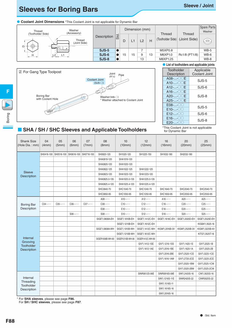
F88 F89
Bor
ing
F
Bor
ing
FBoring Bar with Coolant Hole
Joint(R1/8) Pipe
Washer(WB-○)* Washer attached to Coolant Joint
□ For Gang Type Toolpost
Coolant Joint (SJS-○)
2
Description Std
.
Dimension (mm)Thread
(Toolholder Side)
Thread
(Joint Side)
Spare PartsWasher
D L1 L2 H
SJS-5 ●15 15
713
M5XP0.8Rc1/8 (PT1/8)
WB-5
SJS-6 ● 9 M6XP1.0 WB-6SJS-8 ● 13 M8XP1.25 WB-8
Coolant Joint Dimensions *This Coolant Joint is not applicable for Dynamic Bar
Thread (Toolholder Side)
D
H
Thread(Joint Side)
Washer(Accessory)
L2 L1
List of toolholders and applicable joints
SHA / SH / SHC Sleeves and Applicable Toolholders
Shank Size(Hole Dia. : mm)
04 (4mm)
05 (5mm)
06 (6mm)
07 (7mm)
08 (8mm)
10 (10mm)
12 (12mm)
16 (16mm)
20 (20mm)
25 (25mm)
Sleeve Description
SH0416-100 SH0516-100 SH0616-100 SH0716-100 SH0820-120 SH1020-120 SH1225-150 SH1632-180 SH2032-180
SHA0819-120 SHA1019-120
SHA0820-120 SHA1020-120
SHA0822-125 SHA1022-125 SHA1222-125
SHA0823-120 SHA1023-120 SHA1223-120
SHA0825.0-135 SHA1025.0-135 SHA1225.0-135
SHA0825.4-120 SHA1025.4-120 SHA1225.4-120
SHC0840-70 SHC1040-70 SHC1240-70 SHC1640-70 SHC2040-70 SHC2540-70
SHC0850-95 SHC1050-95 SHC1250-95 SHC1650-95 SHC2050-95 SHC2550-95
Boring Bar Description
A08・-・・・ A10・-・・・ A12・-・・・ A16・-・・・ A20・-・・・ A25・-・・・
C04・-・・・ C05・-・・・ C06・-・・・ C07・-・・・ C08・-・・・ C10・-・・・ C12・-・・・ C16・-・・・ C20・-・・・ C25・-・・・
E08・-・・・ E10・-・・・ E12・-・・・ E16・-・・・ E20・-・・・ E25・-・・・
S06・-・・・ S08・-・・・ S10・-・・・ S12・-・・・ S16・-・・・ S20・-・・・ S25・-・・・
Internal Grooving
Toolholder Description
SIGE&0808A-EH SIGE&1010B-EH SIGE&1412C-EH SIGE&1616C-EH SIGE&2020D-EH SIGE&2525E-EH
SIGE&1210B-EH SIGE&1612C-EH KIGBA&3525-16
SIGE&0808A-WH SIGE&1010B-WH SIGE&1412C-WH KIGM&2016B-3V KIGM&2520B-3V KIGM&3225B-4V
SIGE&1210B-WH SIGE&1612C-WH KITG&3525T-16
SIGER1008B-WH-90 SIGER1210B-WH-90 SIGER1412C-WH-90
GIV&1412-1SE GIV&1216-1SS GIV&1420-1S GIV&2025-1B
GIV&1612-1AE GIV&2016-1BE GIV&1620-1A GIV&2025-2B
GIV&2016-2BE GIV&2520-1CE GIV&3225-1CE
GIV&1616-1AW GIV&2720-2CE GIV&3225-2CE
GIV&2020-1BW GIV&2525-1CW
GIV&2020-2BW GIV&2525-2CW
Internal Threading Toolholder Description
SINR0612S-06E SINR0816S-08E SIN&2420S-16 CIN&3025S-16
SIN&1216S-11E SINR2420S-22 CINR3025S-22
SIN&1516S-11
SIN&1616S-16
SIN&2016S-16
* For SHA sleeves, please see page F86. For SH / SHC sleeves, please see page F87.
● : Std. Item
Sleeves for Boring BarsSleeve / Joint
Toolholder Description
Applicable Coolant Joint
A08-···-OOESJS-5
A10-···-OOEA12-···-OOE SJS-6A16-···-OOE
SJS-8A20-···-OOEA25-···-OOEE08-···-OO SJS-5E10-···-OOE12-···-OO SJS-6E16-···-OO SJS-8E20-···-OO
*This Coolant Joint is not applicable for Dynamic Bar
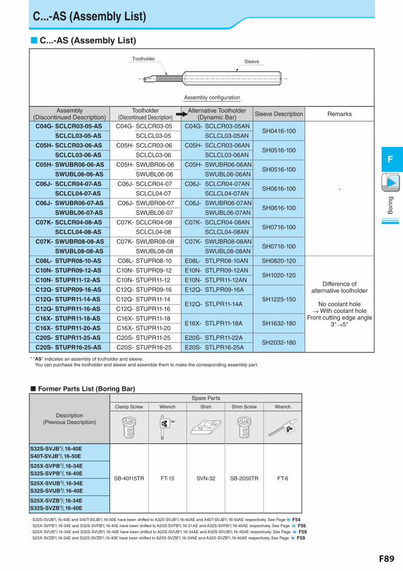
F88 F89
Bor
ing
F
Bor
ing
F
C...-AS (Assembly List)
C...-AS (Assembly List)
Assembly(Discontinued Description)
Toolholder(Discontinued Description)
Alternative Toolholder(Dynamic Bar) Sleeve Description Remarks
C04G- SCLCR03-05-AS C04G- SCLCR03-05 C04G- SCLCR03-05ANSH0416-100
-
SCLCL03-05-AS SCLCL03-05 SCLCL03-05AN
C05H- SCLCR03-06-AS C05H- SCLCR03-06 C05H- SCLCR03-06ANSH0516-100
SCLCL03-06-AS SCLCL03-06 SCLCL03-06AN
C05H- SWUBR06-06-AS C05H- SWUBR06-06 C05H- SWUBR06-06ANSH0516-100
SWUBL06-06-AS SWUBL06-06 SWUBL06-06AN
C06J- SCLCR04-07-AS C06J- SCLCR04-07 C06J- SCLCR04-07ANSH0616-100
SCLCL04-07-AS SCLCL04-07 SCLCL04-07AN
C06J- SWUBR06-07-AS C06J- SWUBR06-07 C06J- SWUBR06-07ANSH0616-100
SWUBL06-07-AS SWUBL06-07 SWUBL06-07AN
C07K- SCLCR04-08-AS C07K- SCLCR04-08 C07K- SCLCR04-08ANSH0716-100
SCLCL04-08-AS SCLCL04-08 SCLCL04-08AN
C07K- SWUBR08-08-AS C07K- SWUBR08-08 C07K- SWUBR08-08ANSH0716-100
SWUBL08-08-AS SWUBL08-08 SWUBL08-08AN
C08L- STUPR08-10-AS C08L- STUPR08-10 E08L- STLPR08-10AN SH0820-120
Difference of alternative toolholder
No coolant hole
→ With coolant hole Front cutting edge angle
3°→5°
C10N- STUPR09-12-AS C10N- STUPR09-12 E10N- STLPR09-12ANSH1020-120
C10N- STUPR11-12-AS C10N- STUPR11-12 E10N- STLPR11-12AN
C12Q- STUPR09-16-AS C12Q- STUPR09-16 E12Q- STLPR09-16A
SH1225-150C12Q- STUPR11-14-AS C12Q- STUPR11-14E12Q- STLPR11-14A
C12Q- STUPR11-16-AS C12Q- STUPR11-16
C16X- STUPR11-18-AS C16X- STUPR11-18E16X- STLPR11-18A SH1632-180
C16X- STUPR11-20-AS C16X- STUPR11-20
C20S- STUPR11-25-AS C20S- STUPR11-25 E20S- STLPR11-22ASH2032-180
C20S- STUPR16-25-AS C20S- STUPR16-25 E20S- STLPR16-25A
* "AS" indicates an assembly of toolholder and sleeve. You can purchase the toolholder and sleeve and assemble them to make the corresponding assembly part.
SleeveToolholder
Assembly con�guration
Former Parts List (Boring Bar)
Description (Previous Description)
Spare Parts
Clamp Screw Wrench Shim Shim Screw Wrench
S32S-SVJB&16-40ES40T-SVJB&16-50E
SB-40115TR FT-15 SVN-32 SB-2050TR FT-6
S25X-SVPB&16-34ES32S-SVPB&16-40E
S25X-SVUB&16-34ES32S-SVUB&16-40E
S25X-SVZB&16-34ES32S-SVZB&16-40E
· S32S-SVJB&16-40E and S40T-SVJB&16-50E have been shifted to A32S-SVJB&16-40AE and A40T-SVJB&16-50AE respectively. See Page F54· S25X-SVPB&16-34E and S32S-SVPB&16-40E have been shifted to A25S-SVPB&16-31AE and A32S-SVPB&16-40AE respectively. See Page F56· S25X-SVUB&16-34E and S32S-SVUB&16-40E have been shifted to A25S-SVUB&16-34AE and A32S-SVUB&16-40AE respectively. See Page F59· S25X-SVZB&16-34E and S32S-SVZB&16-40E have been shifted to A25S-SVZB&16-34AE and A32S-SVZB&16-40AE respectively. See Page F59
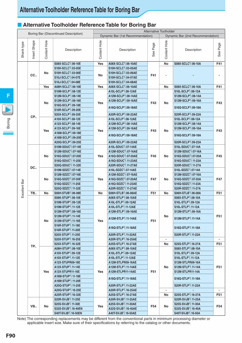
F90 F91
Bor
ing
F
Bor
ing
F
Alternative Toolholder Reference Table for Boring Bar
Boring Bar (Discontinued Description)Alternative Toolholder
Dynamic Bar (1st Recommendation) Dynamic Bar (2nd Recommendation)
Sha
nk ty
pe
Inse
rt S
hape
Coo
lant
Hol
eDescription
Coo
lant
Hol
e
Description
See
Pag
e
Coo
lant
Hol
e
Description
See
Pag
e
Exc
elle
nt B
ar
CC..No
S08X-SCLC&06-10E Yes A08X-SCLC&06-10AE
F41
No S08X-SCLC&06-10A F41S10H-SCLC&03-05E
No
S10H-SCLC&03-05AE
- - -S10H-SCLC&03-06E S10H-SCLC&03-06AES10J-SCLC&04-07E S10H-SCLC&04-07AES10J-SCLC&04-08E S10H-SCLC&04-08AE
Yes A08H-SCLC&06-10E Yes A08X-SCLC&06-10AE No S08X-SCLC&06-10A F41
CP..
No
S10M-SCLP&08-12E
Yes
A10L-SCLP&08-12AE
F43 No
S10L-SCLP&08-12A
F43
S12M-SCLP&08-14E A12M-SCLP&08-14AE S12M-SCLP&08-14AS12M-SCLP&09-16E A12M-SCLP&09-16AE S12M-SCLP&09-16AS16Q-SCLP&09-18E
A16Q-SCLP&09-18AE S16Q-SCLP&09-18AS16R-SCLP&09-20ES20X-SCLP&09-25E A20R-SCLP&09-22AE S20R-SCLP&09-22A
Yes
A10X-SCLP&08-12E
Yes
A10L-SCLP&08-12AE
F43 No
S10L-SCLP&08-12A
F43
A12X-SCLP&08-14E A12M-SCLP&08-14AE S12M-SCLP&08-14AA12X-SCLP&09-16E A12M-SCLP&09-16AE S12M-SCLP&09-16AA16M-SCLP&09-18E
A16Q-SCLP&09-18AE S16Q-SCLP&09-18AA16M-SCLP&09-20EA20Q-SCLP&09-25E A20R-SCLP&09-22AE S20R-SCLP&09-22A
DC..
No
S10M-SDUC&07-14E
Yes
A10L-SDUC&07-14AE
F45 No
S10L-SDUC&07-14A
F45S12M-SDUC&07-16E A12M-SDUC&07-16AE S12M-SDUC&07-16AS16Q-SDUC&07-20E A16Q-SDUC&07-20AE S16Q-SDUC&07-20AS16Q-SDUC&11-25E A16Q-SDUC&11-23AE S16Q-SDUC&11-23AS20Q-SDUC&11-32E A20R-SDUC&11-27AE S20R-SDUC&11-27A
No
S10M-SDZC&07-14E
Yes
A10L-SDZC&07-14AE
F47 No
S10L-SDZC&07-14A
F47S12M-SDZC&07-16E A12M-SDZC&07-16AE S12M-SDZC&07-16AS16Q-SDZC&07-20E A16Q-SDZC&07-20AE S16Q-SDZC&07-20AS16Q-SDZC&11-25E A16Q-SDZC&11-23AE S16Q-SDZC&11-23AS20Q-SDZC&11-32E A20R-SDZC&11-27AE S20R-SDZC&11-27A
TB.. No S06H-STUB&06-08E No S06H-STLB&06-08AE F51 No S06H-STLB&06-08A F51
TP..
No
S08K-STUP&08-10E
Yes
A08X-STLP&08-10AE
F51No
S08X-STLP&08-10A
F51
S10M-STUP&09-12E A10L-STLP&09-12AE S10L-STLP&09-12AS10M-STUP&11-12E A10L-STLP&11-12AE S10L-STLP&11-12AS12M-STUP&09-16E A12M-STLP&09-16AE S12M-STLP&09-16AS12M-STUP&11-14E
A12M-STLP&11-14AE S12M-STLP&11-14AS12M-STUP&11-16ES16R-STUP&11-18E
A16Q-STLP&11-18AE S16Q-STLP&11-18AS16R-STUP&11-20ES20X-STUP&11-25E A20R-STLP&11-22AE S20R-STLP&11-22AS20X-STUP&16-25E A20R-STLP&16-25AE - - -S25X-STUP&16-32E A25S-STLP&16-27AE No S25S-STLP&16-27A F51
Yes
A08H-STUP&08-10E
Yes
A08X-STLP&08-10AE
F51No
S08X-STLP&08-10A
F51
A10X-STUP&09-12E A10L-STLP&09-12AE S10L-STLP&09-12AA10X-STUP&11-12E A10L-STLP&11-12AE S10L-STLP&11-12AA12X-STUPR09-16E A12M-STLPR09-16AE S12M-STLPR09-16AA12X-STUP&11-14E A12M-STLP&11-14AE S12M-STLP&11-14AA12X-STUPR11-16E A12M-STLPR11-14AE S12M-STLPR11-14AA16M-STUP&11-18E
A16Q-STLP&11-18AE S16Q-STLP&11-18AA16M-STUP&11-20EA20Q-STUP&11-25E A20R-STLP&11-22AE S20R-STLP&11-22AA20Q-STUP&16-25E A20R-STLP&16-25AE - - -A25R-STUP&16-32E A25S-STLP&16-27AE No S25S-STLP&16-27A F51
VB.. No
S20R-SVJB&11-25E
Yes
A20R-SVJB&11-25AE
F54 No
S20R-SVJB&11-25A
F54S25S-SVJB&11-30E A25S-SVJB&11-30AE S25S-SVJB&11-30AS32S-SVJB&16-40EN A32S-SVJB&16-40AE S32S-SVJB&16-40AS40T-SVJB&16-50EN A40T-SVJB&16-50AE S40T-SVJB&16-50A
Note) The corresponding replacements may be different from the conventional parts in minimum processing diameter or applicable insert size. Make sure of their specifications by referring to the catalog or other documents.
Alternative Toolholder Reference Table for Boring Bar
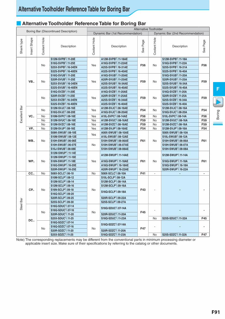
F90 F91
Bor
ing
F
Bor
ing
F
■ Alternative Toolholder Reference Table for Boring BarBoring Bar (Discontinued Description)
Alternative ToolholderDynamic Bar (1st Recommendation) Dynamic Bar (2nd Recommendation)
Sha
nk ty
pe
Inse
rt S
hape
Coo
lant
Hol
eDescription
Coo
lant
Hol
e
Description
See
Pag
e
Coo
lant
Hol
e
Description
See
Pag
e
Exc
elle
nt B
ar
VB..
No
S12M-SVPB&11-20E
Yes
A12M-SVPB&11-18AE
F56 No
S12M-SVPB&11-18A
F56S16Q-SVPB&11-25E A16Q-SVPB&11-22AE S16Q-SVPB&11-22AS25X-SVPB&16-34EN A25S-SVPB&16-31AE S25S-SVPB&16-31AS32S-SVPB&16-40EN A32S-SVPB&16-40AE S32S-SVPB&16-40A
No
S16Q-SVUB&11-20E
Yes
A16Q-SVUB&11-20AE
F59 No
S16Q-SVUB&11-20A
F59S20R-SVUB&11-25E A20R-SVUB&11-25AE S20R-SVUB&11-25AS25X-SVUB&16-34EN A25S-SVUB&16-34AE S25S-SVUB&16-34AS32S-SVUB&16-40EN A32S-SVUB&16-40AE S32S-SVUB&16-40A
No
S16Q-SVZB&11-20E
Yes
A16Q-SVZB&11-20AE
F59 No
S16Q-SVZB&11-20A
F59S20R-SVZB&11-25E A20R-SVZB&11-25AE S20R-SVZB&11-25AS25X-SVZB&16-34EN A25S-SVZB&16-34AE S25S-SVZB&16-34AS32S-SVZB&16-40EN A32S-SVZB&16-40AE S32S-SVZB&16-40A
VC..
NoS12M-SVJC&08-16E
YesA12M-SVJC&08-16AE
F54 NoS12M-SVJC&08-16A
F54S16Q-SVJC&08-20E A16Q-SVJC&08-20AE S16Q-SVJC&08-20A
No S10M-SVPC&08-16E Yes A10L-SVPC&08-14AE F56 No S10L-SVPC&08-14A F56No S12M-SVUC&08-16E Yes A12M-SVUC&08-16AE F59 No S12M-SVUC&08-16A F59No S12M-SVZC&08-16E Yes A12M-SVZC&08-16AE F59 No S12M-SVZC&08-16A F59
VP.. No S12M-SVJP&08-16E Yes A12M-SVJP&08-16AE F54 No S12M-SVJP&08-16A F54
WB.. No
S08K-SWUB&08-10EYes
A08X-SWUB&08-10AE
F61 No
S08X-SWUB&08-10A
F61S10M-SWUB&08-12E A10L-SWUB&08-12AE S10L-SWUB&08-12AS10H-SWUB&06-06E
NoS10H-SWUB&06-06AE S10H-SWUB&06-06A
S10H-SWUB&06-07E S10H-SWUB&06-07AE S10H-SWUB&06-07AS10J-SWUB&08-08E S10H-SWUB&08-08AE S10H-SWUB&08-08A
WP.. No
S12M-SWUP&11-14E
Yes
A12M-SWUP&11-14AE
F61 No
S12M-SWUP&11-14A
F61S12M-SWUP&11-16ES16N-SWUP&11-18E A16Q-SWUP&11-18AE S16Q-SWUP&11-18AS16Q-SWUP&16-20E A16Q-SWUP&16-18AE S16Q-SWUP&16-18AS20R-SWUP&16-25E A20R-SWUP&16-22AE S20R-SWUP&16-22A
Ste
el B
ar
CC.. No S08X-SCLC&06-10 No S08X-SCLC&06-10A F41 - - -
CP.. No
S10M-SCLP&08-12
No
S10L-SCLP&08-12A
F43 - - -
S12M-SCLP&08-14 S12M-SCLP&08-14AS12M-SCLP&09-16 S12M-SCLP&09-16AS16N-SCLP&09-18
S16Q-SCLP&09-18AS16Q-SCLP&09-20S20R-SCLP&09-25 S20R-SCLP&09-22AS25S-SCLP&09-30 S25S-SCLP&09-27A
DC..
No
S16Q-SDUC&07-14
NoS16Q-SDUC&07-14A
F45- - -S16Q-SDUC&07-16
S20R-SDUC&11-20 S20R-SDUC&11-20AS25X-SDUC&11-25 S16Q-SDUC&11-23A No S25S-SDUC&11-32A F45
No
S16Q-SDZC&07-14
NoS16Q-SDZC&07-14A
F47- - -S16Q-SDZC&07-16
S20R-SDZC&11-20 S20R-SDZC&11-20AS25X-SDZC&11-25 S16Q-SDZC&11-23A No S25S-SDZC&11-32A F47
Note) The corresponding replacements may be different from the conventional parts in minimum processing diameter or applicable insert size. Make sure of their specifications by referring to the catalog or other documents.
Alternative Toolholder Reference Table for Boring Bar
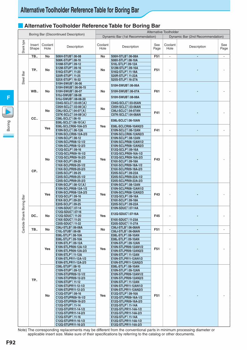
F92 F93
Bor
ing
F
Bor
ing
F
■ Alternative Toolholder Reference Table for Boring BarBoring Bar (Discontinued Description)
Alternative ToolholderDynamic Bar (1st Recommendation) Dynamic Bar (2nd Recommendation)
Shan
k ty
pe
Insert Shape
Coolant Hole Description Coolant
Hole Description See Page
Coolant Hole Description See
Page
Ste
el B
ar
TB.. No S06H-STUB&06-08 No S06H-STLB&06-08A F51 - - -
TP.. No
S08K-STUP&08-10
No
S08X-STLP&08-10A
F51 - - -
S10M-STUP&09-12 S10L-STLP&09-12AS12M-STUP&09-16 S12M-STLP&09-16AS16Q-STUP&11-20 S16Q-STLP&11-18AS20R-STUP&11-25 S20R-STLP&11-22AS25X-STUP&16-32 S25S-STLP&16-27A
WB.. No
S10H-SWUB&06-06
No
S10H-SWUB&06-06A
F61 - - -S10H-SWUB&06-06-15S10H-SWUB&06-07 S10H-SWUB&06-07AS10J-SWUB&08-08 S10H-SWUB&08-08AS10J-SWUB&08-08-20
Car
bide
Sha
nk B
orin
g B
ar
CC..
No
C04G-SCLC&03-05(A)
No
C04G-SCLC&03-05AN
F41 - - -
C05H-SCLC&03-06(A) C05H-SCLC&03-06ANC06J-SCLC&04-07(A) C06J-SCLC&04-07ANC07K-SCLC&04-08(A) C07K-SCLC&04-08ANC08L-SCLC&06-10
Yes
E08L-SCLC&06-10AN
Yes
E08L-SCLC&06-10(A)E08L-SCLCR06-10A-2/3 E08L-SCLCR06-10AN2/3
F41 - - -E10N-SCLC&06-12A E10N-SCLC&06-12ANE10N-SCLCR06-12A-2/3 E10N-SCLCR06-12AN2/3
CP..
No
C10N-SCLP&08-12
Yes
E10N-SCLP&08-12AN
F43 - - -
C10N-SCLPR08-12-1/2 E10N-SCLPR08-12AN1/2C10N-SCLPR08-12-2/3 E10N-SCLPR08-12AN2/3C12Q-SCLP&09-16 E12Q-SCLP&09-16AC12Q-SCLPR09-16-1/2 E12Q-SCLPR09-16A-1/2C12Q-SCLPR09-16-2/3 E12Q-SCLPR09-16A-2/3C16X-SCLP&09-20 E16X-SCLP&09-18AC16X-SCLPR09-20-1/2 E16X-SCLPR09-18A-1/2C16X-SCLPR09-20-2/3 E16X-SCLPR09-18A-2/3C20S-SCLP&09-25 E20S-SCLP&09-22AC20S-SCLPR09-25-1/2 E20S-SCLPR09-22A-1/2C20S-SCLPR09-25-2/3 E20S-SCLPR09-22A-2/3
Yes
E10N-SCLP&08-12(A)
Yes
E10N-SCLP&08-12AN
F43 - - -
E10N-SCLPR08-12A-1/2 E10N-SCLPR08-12AN1/2E10N-SCLPR08-12A-2/3 E10N-SCLPR08-12AN2/3E12Q-SCLP&09-16 E12Q-SCLP&09-16AE16X-SCLP&09-20 E16X-SCLP&09-18AE20S-SCLP&09-25 E20S-SCLP&09-22A
DC.. No
C10N-SDUC&07-14
Yes
E10N-SDUC&07-14A
F45 - - -C12Q-SDUC&07-16 E12Q-SDUC&07-16AC12Q-SDUC&11-20C16X-SDUC&11-25 E16X-SDUC&11-23AC20S-SDUC&11-32 E20S-SDUC&11-27A
TB.. No C06J-STLB&06-08A No C06J-STLB&06-08AN F51 - - -C10L-STUB&06-08 C06J-STLB&06-08AN
TP..
Yes
E08L-STLP&08-10A
Yes
E08L-STLP&08-10AN
F51 - - -
E08L-STLP&09-10A E08L-STLP&09-10ANE10N-STLP&09-12A E10N-STLP&09-12ANE10N-STLPR09-12A-1/2 E10N-STLPR09-12AN1/2E10N-STLPR09-12A-2/3 E10N-STLPR09-12AN2/3E10N-STLP&11-12A E10N-STLP&11-12ANE10N-STLPR11-12A-1/2 E10N-STLPR11-12AN1/2E10N-STLPR11-12A-2/3 E10N-STLPR11-12AN2/3
No
C08L-STUP&08-10
Yes
E08L-STLP&08-10AN
F51 - - -
C10N-STUP&09-12 E10N-STLP&09-12ANC10N-STUPR09-12-1/2 E10N-STLPR09-12AN1/2C10N-STUPR09-12-2/3 E10N-STLPR09-12AN2/3C10N-STUP&11-12 E10N-STLP&11-12ANC10N-STUPR11-12-1/2 E10N-STLPR11-12AN1/2C10N-STUPR11-12-2/3 E10N-STLPR11-12AN2/3C12Q-STUP&09-16 E12Q-STLP&09-16AC12Q-STUPR09-16-1/2 E12Q-STLPR09-16A-1/2C12Q-STUPR09-16-2/3 E12Q-STLPR09-16A-2/3C12Q-STUP&11-14 E12Q-STLP&11-14AC12Q-STUPR11-14-1/2 E12Q-STLPR11-14A-1/2C12Q-STUPR11-14-2/3 E12Q-STLPR11-14A-2/3C12Q-STUP&11-16 E12Q-STLP&11-14AC12Q-STUPR11-16-1/2 E12Q-STLPR11-14A-1/2C12Q-STUPR11-16-2/3 E12Q-STLPR11-14A-2/3
Note) The corresponding replacements may be different from the conventional parts in minimum processing diameter or applicable insert size. Make sure of their specifications by referring to the catalog or other documents.
Alternative Toolholder Reference Table for Boring Bar
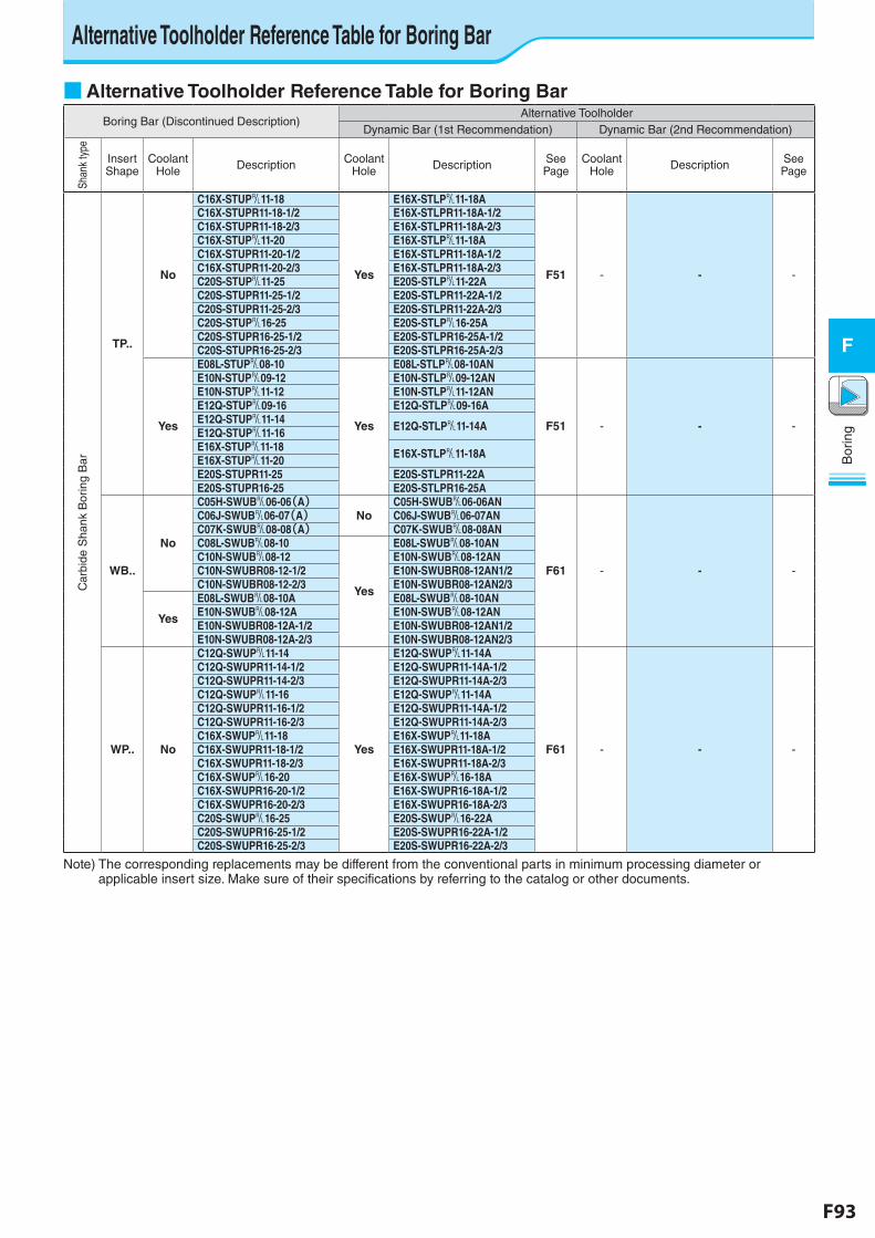
F92 F93
Bor
ing
F
Bor
ing
F
■ Alternative Toolholder Reference Table for Boring BarBoring Bar (Discontinued Description)
Alternative ToolholderDynamic Bar (1st Recommendation) Dynamic Bar (2nd Recommendation)
Shan
k ty
pe
Insert Shape
Coolant Hole Description Coolant
Hole Description See Page
Coolant Hole Description See
Page
Car
bide
Sha
nk B
orin
g B
ar
TP..
No
C16X-STUP&11-18
Yes
E16X-STLP&11-18A
F51 - - -
C16X-STUPR11-18-1/2 E16X-STLPR11-18A-1/2C16X-STUPR11-18-2/3 E16X-STLPR11-18A-2/3C16X-STUP&11-20 E16X-STLP&11-18AC16X-STUPR11-20-1/2 E16X-STLPR11-18A-1/2C16X-STUPR11-20-2/3 E16X-STLPR11-18A-2/3C20S-STUP&11-25 E20S-STLP&11-22AC20S-STUPR11-25-1/2 E20S-STLPR11-22A-1/2C20S-STUPR11-25-2/3 E20S-STLPR11-22A-2/3C20S-STUP&16-25 E20S-STLP&16-25AC20S-STUPR16-25-1/2 E20S-STLPR16-25A-1/2C20S-STUPR16-25-2/3 E20S-STLPR16-25A-2/3
Yes
E08L-STUP&08-10
Yes
E08L-STLP&08-10AN
F51 - - -
E10N-STUP&09-12 E10N-STLP&09-12ANE10N-STUP&11-12 E10N-STLP&11-12ANE12Q-STUP&09-16 E12Q-STLP&09-16AE12Q-STUP&11-14 E12Q-STLP&11-14AE12Q-STUP&11-16E16X-STUP&11-18 E16X-STLP&11-18AE16X-STUP&11-20E20S-STUPR11-25 E20S-STLPR11-22AE20S-STUPR16-25 E20S-STLPR16-25A
WB..
No
C05H-SWUB&06-06(A)No
C05H-SWUB&06-06AN
F61 - - -
C06J-SWUB&06-07(A) C06J-SWUB&06-07ANC07K-SWUB&08-08(A) C07K-SWUB&08-08ANC08L-SWUB&08-10
Yes
E08L-SWUB&08-10ANC10N-SWUB&08-12 E10N-SWUB&08-12ANC10N-SWUBR08-12-1/2 E10N-SWUBR08-12AN1/2C10N-SWUBR08-12-2/3 E10N-SWUBR08-12AN2/3
Yes
E08L-SWUB&08-10A E08L-SWUB&08-10ANE10N-SWUB&08-12A E10N-SWUB&08-12ANE10N-SWUBR08-12A-1/2 E10N-SWUBR08-12AN1/2E10N-SWUBR08-12A-2/3 E10N-SWUBR08-12AN2/3
WP.. No
C12Q-SWUP&11-14
Yes
E12Q-SWUP&11-14A
F61 - - -
C12Q-SWUPR11-14-1/2 E12Q-SWUPR11-14A-1/2C12Q-SWUPR11-14-2/3 E12Q-SWUPR11-14A-2/3C12Q-SWUP&11-16 E12Q-SWUP&11-14AC12Q-SWUPR11-16-1/2 E12Q-SWUPR11-14A-1/2C12Q-SWUPR11-16-2/3 E12Q-SWUPR11-14A-2/3C16X-SWUP&11-18 E16X-SWUP&11-18AC16X-SWUPR11-18-1/2 E16X-SWUPR11-18A-1/2C16X-SWUPR11-18-2/3 E16X-SWUPR11-18A-2/3C16X-SWUP&16-20 E16X-SWUP&16-18AC16X-SWUPR16-20-1/2 E16X-SWUPR16-18A-1/2C16X-SWUPR16-20-2/3 E16X-SWUPR16-18A-2/3C20S-SWUP&16-25 E20S-SWUP&16-22AC20S-SWUPR16-25-1/2 E20S-SWUPR16-22A-1/2C20S-SWUPR16-25-2/3 E20S-SWUPR16-22A-2/3
Note) The corresponding replacements may be different from the conventional parts in minimum processing diameter or applicable insert size. Make sure of their specifications by referring to the catalog or other documents.
Alternative Toolholder Reference Table for Boring Bar
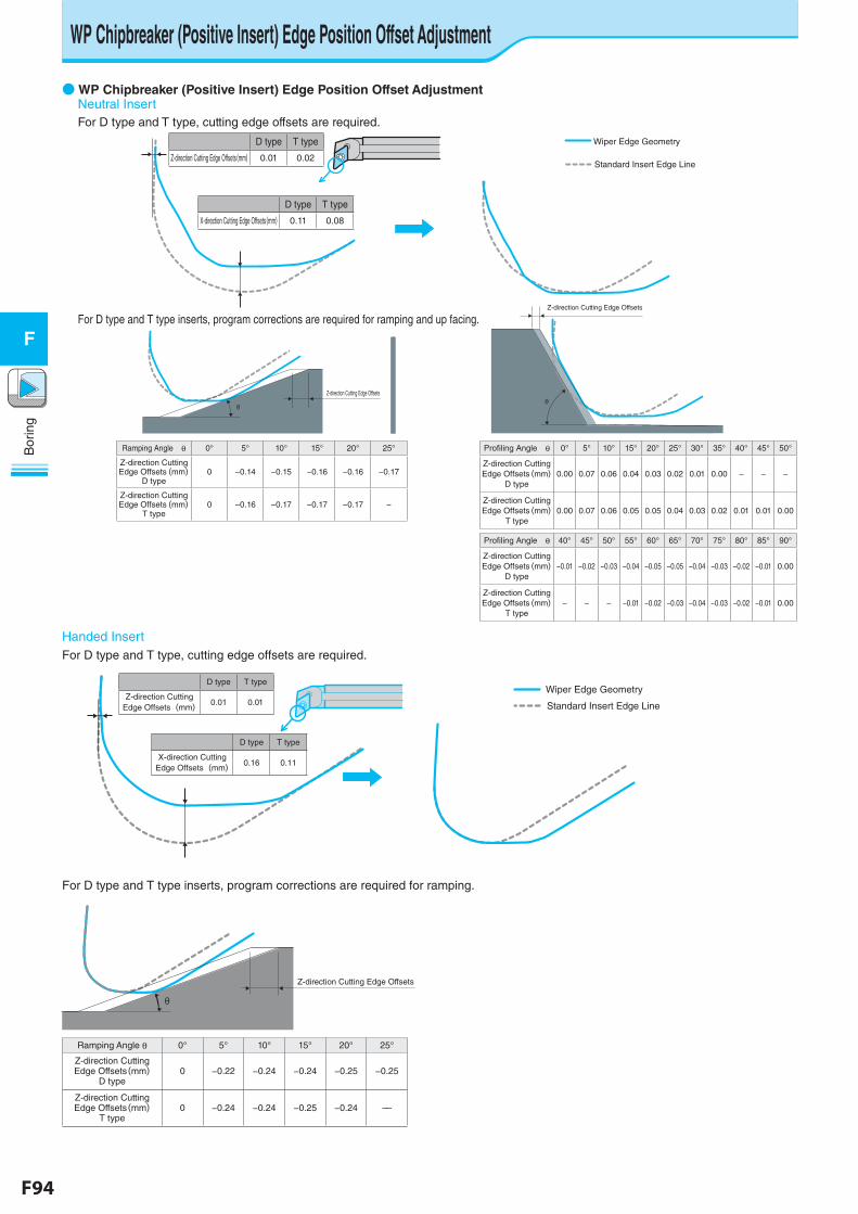
F94 F95
Bor
ing
F
Bor
ing
F
WP Chipbreaker (Positive Insert) Edge Position Offset Adjustment
Standard Insert Edge Line
Z-direction Cutting Edge Offsets
Z-direction Cutting Edge Offsets
Wiper Edge Geometry
θ θ
For D type and T type, cutting edge offsets are required.
D type T type
Z-direction Cutting Edge Offsets(mm) 0.01 0.02
D type T type
X-direction Cutting Edge Offsets(mm) 0.11 0.08
Ramping Angle θ 0° 5° 10° 15° 20° 25°
Z-direction Cutting Edge Offsets(mm)
D type0 −0.14 −0.15 −0.16 −0.16 −0.17
Z-direction Cutting Edge Offsets(mm)
T type0 −0.16 −0.17 −0.17 −0.17 −
Profiling Angle θ 0° 5° 10° 15° 20° 25° 30° 35° 40° 45° 50°
Z-direction Cutting Edge Offsets(mm)
D type0.00 0.07 0.06 0.04 0.03 0.02 0.01 0.00 − − −
Z-direction Cutting Edge Offsets(mm)
T type0.00 0.07 0.06 0.05 0.05 0.04 0.03 0.02 0.01 0.01 0.00
Profiling Angle θ 40° 45° 50° 55° 60° 65° 70° 75° 80° 85° 90°
Z-direction Cutting Edge Offsets(mm)
D type−0.01 −0.02 −0.03 −0.04 −0.05 −0.05 −0.04 −0.03 −0.02 −0.01 0.00
Z-direction Cutting Edge Offsets(mm)
T type− − − −0.01 −0.02 −0.03 −0.04 −0.03 −0.02 −0.01 0.00
Standard Insert Edge Line
Z-direction Cutting Edge Offsets
Z-direction Cutting Edge Offsets
Wiper Edge Geometry
θ θ
Standard Insert Edge Line
Z-direction Cutting Edge Offsets
Z-direction Cutting Edge Offsets
Wiper Edge Geometry
θ θ
For D type and T type inserts, program corrections are required for ramping and up facing.
● WP Chipbreaker (Positive Insert) Edge Position Offset AdjustmentNeutral Insert
For D type and T type, cutting edge offsets are required.
For D type and T type inserts, program corrections are required for ramping.
Standard Insert Edge Line
Wiper Edge Geometry
Z-direction Cutting Edge Offsets
θ
D type T type
Z-direction Cutting Edge Offsets(mm) 0.01 0.01
D type T type
X-direction Cutting Edge Offsets(mm) 0.16 0.11
Ramping Angle θ 0° 5° 10° 15° 20° 25°
Z-direction Cutting Edge Offsets(mm)
D type 0 −0.22 −0.24 −0.24 −0.25 −0.25
Z-direction Cutting Edge Offsets(mm)
T type0 −0.24 −0.24 −0.25 −0.24 ––
Standard Insert Edge Line
Wiper Edge Geometry
Z-direction Cutting Edge Offsets
θ
Handed Insert
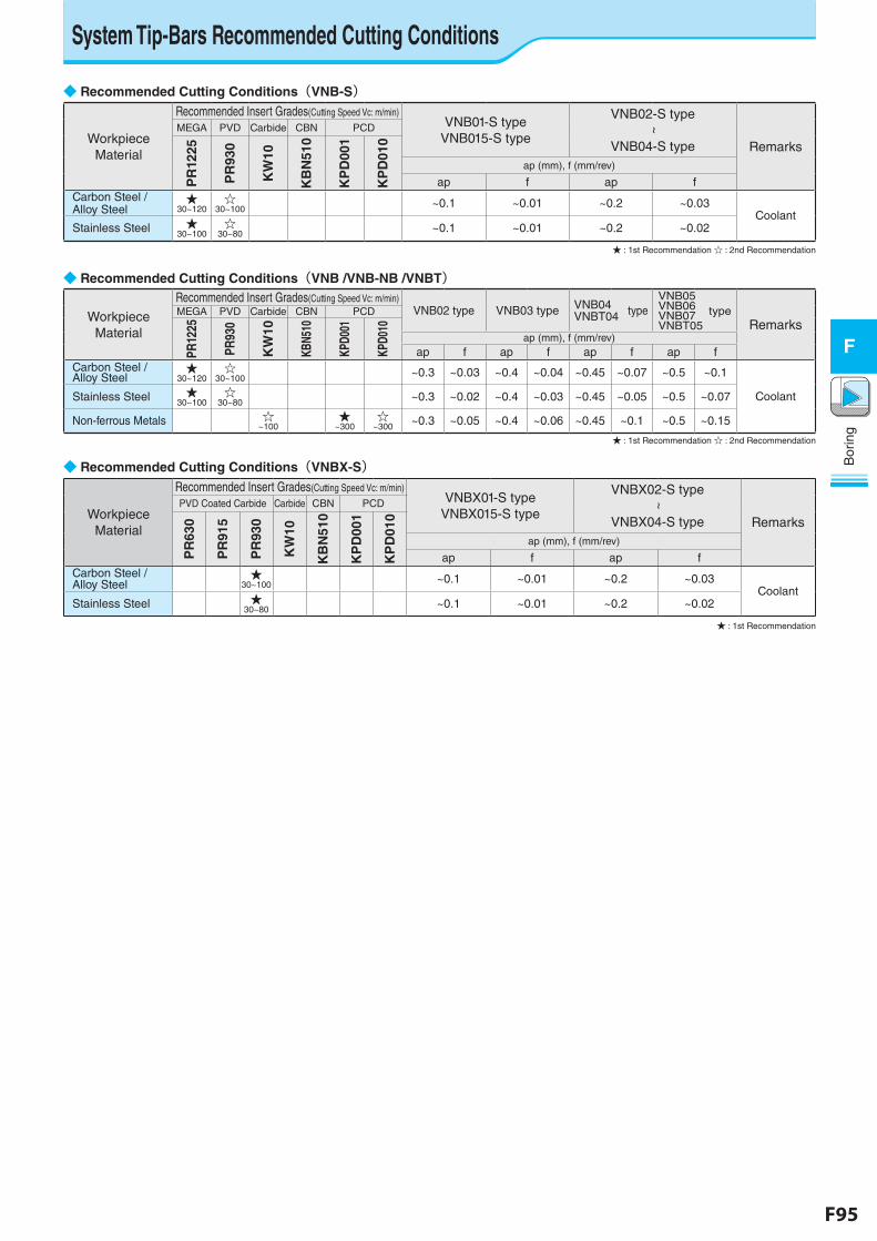
F94 F95
Bor
ing
F
Bor
ing
F
◆ Recommended Cutting Conditions(VNB-S)
Workpiece Material
Recommended Insert Grades(Cutting Speed Vc: m/min)VNB01-S type
VNB015-S type
VNB02-S type
~
VNB04-S type Remarks
MEGA PVD Carbide CBN PCD
PR
1225
PR
930
KW
10
KB
N51
0
KP
D00
1
KP
D01
0
ap (mm), f (mm/rev)
ap f ap fCarbon Steel /Alloy Steel
★30~120
☆30~100 ~0.1 ~0.01 ~0.2 ~0.03
CoolantStainless Steel ★
30~100☆
30~80 ~0.1 ~0.01 ~0.2 ~0.02
★ : 1st Recommendation ☆ : 2nd Recommendation
◆ Recommended Cutting Conditions(VNB /VNB-NB /VNBT)
Workpiece Material
Recommended Insert Grades(Cutting Speed Vc: m/min)VNB02 type VNB03 type VNB04
VNBT04 typeVNB05 VNB06 VNB07 typeVNBT05 Remarks
MEGA PVD Carbide CBN PCD
PR12
25
PR93
0
KW
10
KBN5
10
KPD0
01
KPD0
10
ap (mm), f (mm/rev)ap f ap f ap f ap f
Carbon Steel / Alloy Steel
★30~120
☆30~100 ~0.3 ~0.03 ~0.4 ~0.04 ~0.45 ~0.07 ~0.5 ~0.1
CoolantStainless Steel ★30~100
☆30~80 ~0.3 ~0.02 ~0.4 ~0.03 ~0.45 ~0.05 ~0.5 ~0.07
Non-ferrous Metals ☆~100
★~300
☆~300 ~0.3 ~0.05 ~0.4 ~0.06 ~0.45 ~0.1 ~0.5 ~0.15
★ : 1st Recommendation ☆ : 2nd Recommendation
◆ Recommended Cutting Conditions(VNBX-S)
Workpiece Material
Recommended Insert Grades(Cutting Speed Vc: m/min)VNBX01-S type
VNBX015-S type
VNBX02-S type
~
VNBX04-S type Remarks
PVD Coated Carbide Carbide CBN PCD
PR
630
PR
915
PR
930
KW
10
KB
N51
0
KP
D00
1
KP
D01
0
ap (mm), f (mm/rev)
ap f ap fCarbon Steel / Alloy Steel
★30~100 ~0.1 ~0.01 ~0.2 ~0.03
CoolantStainless Steel ★
30~80 ~0.1 ~0.01 ~0.2 ~0.02
★ : 1st Recommendation
System Tip-Bars Recommended Cutting Conditions
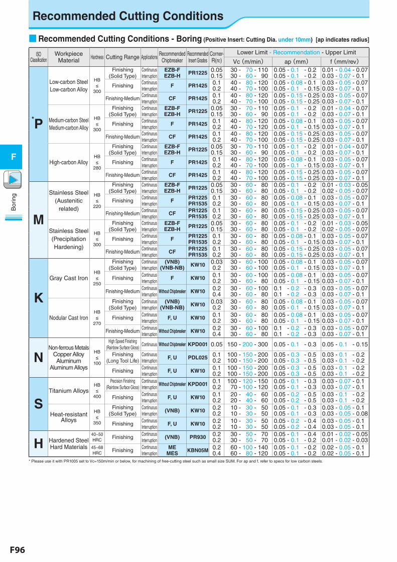
F96 F97
Bor
ing
F
Bor
ing
F
Recommended Cutting Conditions
■ Recommended Cutting Conditions - Boring (Positive Insert: Cutting Dia. under 10mm) [ap indicates radius]
ISO Classification
Workpiece Material Hardness Cutting Range Applications Recommended
ChipbreakerRecommended Insert Grades
Corner-R(re)
Lower Limit - Recommendation - Upper Limit
Vc(m/min) ap(mm) f(mm/rev)
*P
Low-carbon Steel Low-carbon Alloy
HB≤
300
Finishing (Solid Type)
Continuous Interruption
EZB-FEZB-H PR1225 0.05
0.15 30 - 70 - 110 30 - 60 - 90
0.05 - 0.1 - 0.20.05 - 0.1 - 0.2
0.01 - 0.04 - 0.070.03 - 0.07 - 0.1
FinishingContinuous Interruption
F PR1425 0.10.2
40 - 80 - 120 40 - 70 - 100
0.05 - 0.08 - 0.10.05 - 0.1 - 0.15
0.03 - 0.05 - 0.070.03 - 0.07 - 0.1
Finishing-MediumContinuous Interruption
CF PR1425 0.10.2
40 - 80 - 120 40 - 70 - 100
0.05 - 0.15 - 0.250.05 - 0.15 - 0.25
0.03 - 0.05 - 0.070.03 - 0.07 - 0.1
Medium-carbon Steel Medium-carbon Alloy
HB≤
300
Finishing (Solid Type)
Continuous Interruption
EZB-FEZB-H PR1225 0.05
0.15 30 - 70 - 110 30 - 60 - 90
0.05 - 0.1 - 0.20.05 - 0.1 - 0.2
0.01 - 0.04 - 0.070.03 - 0.07 - 0.1
FinishingContinuous Interruption
F PR1425 0.10.2
40 - 80 - 120 40 - 70 - 120
0.05 - 0.08 - 0.10.05 - 0.1 - 0.15
0.03 - 0.05 - 0.070.03 - 0.07 - 0.1
Finishing-MediumContinuous Interruption
CF PR1425 0.10.2
40 - 80 - 120 40 - 70 - 100
0.05 - 0.15 - 0.250.05 - 0.15 - 0.25
0.03 - 0.05 - 0.070.03 - 0.07 - 0.1
High-carbon AlloyHB≤
280
Finishing (Solid Type)
Continuous Interruption
EZB-FEZB-H PR1225 0.05
0.15 30 - 70 - 110 30 - 60 - 90
0.05 - 0.1 - 0.20.05 - 0.1 - 0.2
0.01 - 0.04 - 0.070.03 - 0.07 - 0.1
FinishingContinuous Interruption
F PR1425 0.10.2
40 - 80 - 120 40 - 70 - 100
0.05 - 0.08 - 0.10.05 - 0.1 - 0.15
0.03 - 0.05 - 0.070.03 - 0.07 - 0.1
Finishing-MediumContinuous Interruption
CF PR1425 0.10.2
40 - 80 - 120 40 - 70 - 100
0.05 - 0.15 - 0.250.05 - 0.15 - 0.25
0.03 - 0.05 - 0.070.03 - 0.07 - 0.1
M
Stainless Steel(Austenitic
related)
HB≤
220
Finishing (Solid Type)
Continuous Interruption
EZB-FEZB-H PR1225 0.05
0.15 30 - 60 - 80 30 - 60 - 80
0.05 - 0.1 - 0.20.05 - 0.1 - 0.2
0.01 - 0.03 - 0.050.02 - 0.05 - 0.07
FinishingContinuous Interruption
F PR1225PR1535
0.10.2
30 - 60 - 80 30 - 60 - 80
0.05 - 0.08 - 0.10.05 - 0.1 - 0.15
0.03 - 0.05 - 0.070.03 - 0.07 - 0.1
Finishing-MediumContinuous Interruption
CF PR1225PR1535
0.10.2
30 - 60 - 80 30 - 60 - 80
0.05 - 0.15 - 0.250.05 - 0.15 - 0.25
0.03 - 0.05 - 0.070.03 - 0.07 - 0.1
Stainless Steel(Precipitation Hardening)
HB≤
300
Finishing (Solid Type)
Continuous Interruption
EZB-FEZB-H PR1225 0.05
0.15 30 - 60 - 80 30 - 60 - 80
0.05 - 0.1 - 0.20.05 - 0.1 - 0.2
0.01 - 0.03 - 0.050.02 - 0.05 - 0.07
FinishingContinuous Interruption
F PR1225PR1535
0.10.2
30 - 60 - 80 30 - 60 - 80
0.05 - 0.08 - 0.10.05 - 0.1 - 0.15
0.03 - 0.05 - 0.070.03 - 0.07 - 0.1
Finishing-MediumContinuous Interruption
CF PR1225PR1535
0.10.2
30 - 60 - 80 30 - 60 - 80
0.05 - 0.15 - 0.250.05 - 0.15 - 0.25
0.03 - 0.05 - 0.070.03 - 0.07 - 0.1
K
Gray Cast IronHB≤
250
Finishing (Solid Type)
Continuous Interruption
(VNB)(VNB-NB) KW10 0.03
0.2 30 - 60 - 100 30 - 60 - 100
0.05 - 0.08 - 0.10.05 - 0.1 - 0.15
0.03 - 0.05 - 0.070.03 - 0.07 - 0.1
FinishingContinuous Interruption
F KW10 0.10.2
30 - 60 - 100 30 - 60 - 80
0.05 - 0.08 - 0.10.05 - 0.1 - 0.15
0.03 - 0.05 - 0.070.03 - 0.07 - 0.1
Finishing-MediumContinuous Interruption
Without Chipbreaker KW10 0.20.4
30 - 60 - 100 30 - 60 - 80
0.1 - 0.2 - 0.30.1 - 0.2 - 0.3
0.03 - 0.05 - 0.070.03 - 0.07 - 0.1
Nodular Cast IronHB≤
270
Finishing (Solid Type)
Continuous Interruption
(VNB)(VNB-NB) KW10 0.03
0.2 30 - 60 - 80 30 - 60 - 80
0.05 - 0.08 - 0.10.05 - 0.1 - 0.15
0.03 - 0.05 - 0.070.03 - 0.07 - 0.1
FinishingContinuous Interruption
F, U KW10 0.10.2
30 - 60 - 80 30 - 60 - 80
0.05 - 0.08 - 0.10.05 - 0.1 - 0.15
0.03 - 0.05 - 0.070.03 - 0.07 - 0.1
Finishing-MediumContinuous Interruption
Without Chipbreaker KW10 0.20.4
30 - 60 - 100 30 - 60 - 80
0.1 - 0.2 - 0.30.1 - 0.2 - 0.3
0.03 - 0.05 - 0.070.03 - 0.07 - 0.1
NNon-ferrous Metals
Copper Alloy Aluminum
Aluminum Alloys
HB≤
100
High Speed Finishing (Rainbow Surface Gloss)
Continuous Without Chipbreaker KPD001 0.05 150 - 200 - 300 0.05 - 0.1 - 0.3 0.05 - 0.1 - 0.15
Finishing (Long Tool Life)
Continuous Interruption
F, U PDL025 0.10.2
100 - 150 - 200100 - 150 - 200
0.05 - 0.3 - 0.50.05 - 0.3 - 0.5
0.03 - 0.1 - 0.20.03 - 0.1 - 0.2
FinishingContinuous Interruption
F, U KW10 0.10.2
100 - 150 - 200100 - 150 - 200
0.05 - 0.3 - 0.50.05 - 0.3 - 0.5
0.03 - 0.1 - 0.20.03 - 0.1 - 0.2
STitanium Alloys
HB≤
400
Precision Finishing (Rainbow Surface Gloss)
Continuous Interruption
Without Chipbreaker KPD001 0.10.2
100 - 120 - 150 70 - 100 - 120
0.05 - 0.1 - 0.30.05 - 0.1 - 0.3
0.03 - 0.07 - 0.10.03 - 0.07 - 0.1
FinishingContinuous Interruption
F, U KW10 0.10.2
20 - 40 - 60 20 - 40 - 60
0.05 - 0.2 - 0.50.05 - 0.2 - 0.5
0.03 - 0.1 - 0.20.03 - 0.1 - 0.2
Heat-resistant Alloys
HB≤
350
Finishing (Solid Type)
Continuous Interruption
(VNB) KW10 0.20.2
10 - 30 - 50 10 - 30 - 50
0.05 - 0.1 - 0.30.05 - 0.1 - 0.3
0.03 - 0.05 - 0.10.03 - 0.05 - 0.08
FinishingContinuous Interruption
F, U KW10 0.20.2
10 - 30 - 50 10 - 30 - 50
0.05 - 0.2 - 0.40.05 - 0.2 - 0.4
0.03 - 0.05 - 0.10.03 - 0.05 - 0.1
H Hardened SteelHard Materials
40~50HRC Finishing
Continuous Interruption
(VNB) PR930 0.20.2
30 - 50 - 70 30 - 50 - 70
0.05 - 0.1 - 0.40.05 - 0.1 - 0.2
0.01 - 0.02 - 0.050.01 - 0.02 - 0.03
45~68HRC Finishing
Continuous Interruption
MEMES KBN05M 0.2
0.4 60 - 100 - 140 60 - 80 - 120
0.05 - 0.1 - 0.20.05 - 0.1 - 0.2
0.02 - 0.05 - 0.10.02 - 0.05 - 0.1
* Please use it with PR1005 set to Vc=150m/min or below, for machining of free-cutting steel such as small size SUM. For ap and f, refer to specs for low carbon steels.
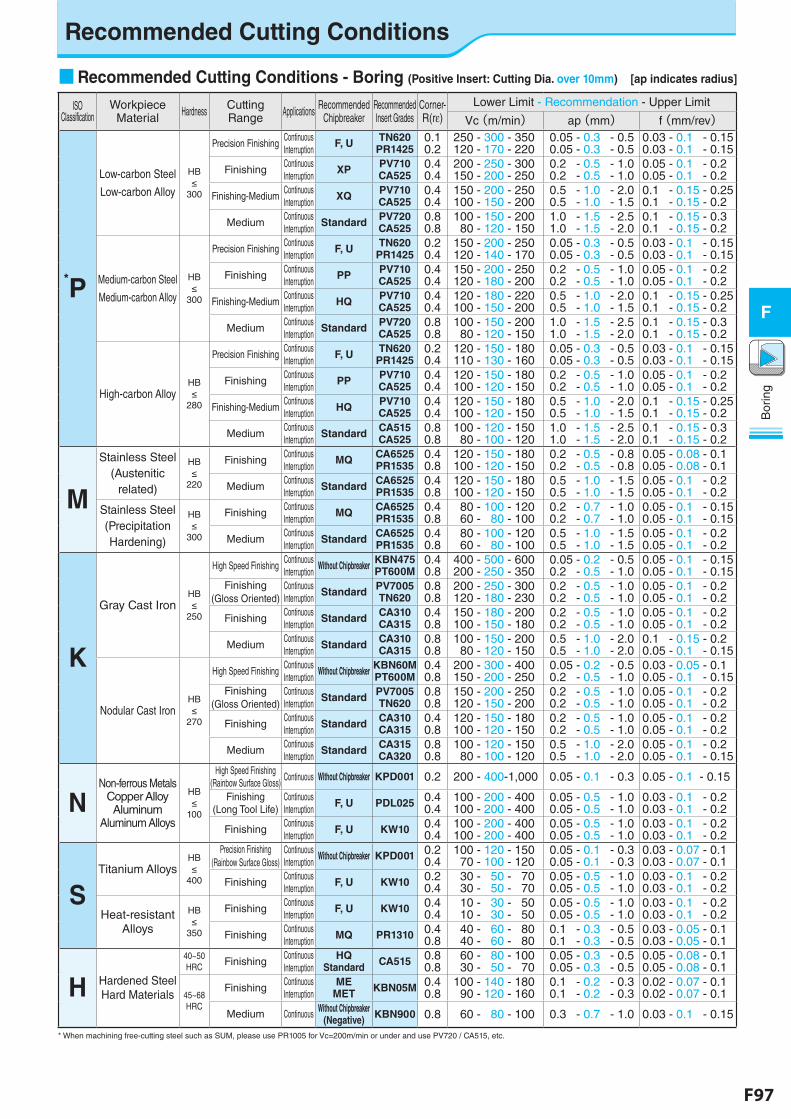
F96 F97
Bor
ing
F
Bor
ing
F
Recommended Cutting Conditions
■ Recommended Cutting Conditions - Boring (Positive Insert: Cutting Dia. over 10mm) [ap indicates radius]
ISO Classification
Workpiece Material Hardness Cutting
Range Applications Recommended Chipbreaker
Recommended Insert Grades
Corner-R(re)
Lower Limit - Recommendation - Upper Limit
Vc(m/min) ap(mm) f(mm/rev)
*P
Low-carbon Steel
Low-carbon Alloy
HB≤
300
Precision FinishingContinuous Interruption
F, U TN620PR1425
0.10.2
250 - 300 - 350120 - 170 - 220
0.05 - 0.3 - 0.50.05 - 0.3 - 0.5
0.03 - 0.1 - 0.150.03 - 0.1 - 0.15
FinishingContinuous Interruption
XP PV710CA525
0.40.4
200 - 250 - 300150 - 200 - 250
0.2 - 0.5 - 1.00.2 - 0.5 - 1.0
0.05 - 0.1 - 0.20.05 - 0.1 - 0.2
Finishing-MediumContinuous Interruption
XQ PV710CA525
0.40.4
150 - 200 - 250100 - 150 - 200
0.5 - 1.0 - 2.00.5 - 1.0 - 1.5
0.1 - 0.15 - 0.250.1 - 0.15 - 0.2
MediumContinuous Interruption
Standard PV720CA525
0.80.8
100 - 150 - 200 80 - 120 - 150
1.0 - 1.5 - 2.51.0 - 1.5 - 2.0
0.1 - 0.15 - 0.30.1 - 0.15 - 0.2
Medium-carbon Steel
Medium-carbon Alloy
HB≤
300
Precision FinishingContinuous Interruption
F, U TN620PR1425
0.20.4
150 - 200 - 250120 - 140 - 170
0.05 - 0.3 - 0.50.05 - 0.3 - 0.5
0.03 - 0.1 - 0.150.03 - 0.1 - 0.15
FinishingContinuous Interruption
PP PV710CA525
0.40.4
150 - 200 - 250120 - 180 - 200
0.2 - 0.5 - 1.00.2 - 0.5 - 1.0
0.05 - 0.1 - 0.20.05 - 0.1 - 0.2
Finishing-MediumContinuous Interruption
HQ PV710CA525
0.40.4
120 - 180 - 220100 - 150 - 200
0.5 - 1.0 - 2.00.5 - 1.0 - 1.5
0.1 - 0.15 - 0.250.1 - 0.15 - 0.2
MediumContinuous Interruption
Standard PV720CA525
0.80.8
100 - 150 - 200 80 - 120 - 150
1.0 - 1.5 - 2.51.0 - 1.5 - 2.0
0.1 - 0.15 - 0.30.1 - 0.15 - 0.2
High-carbon AlloyHB≤
280
Precision FinishingContinuous Interruption
F, U TN620PR1425
0.20.4
120 - 150 - 180110 - 130 - 160
0.05 - 0.3 - 0.50.05 - 0.3 - 0.5
0.03 - 0.1 - 0.150.03 - 0.1 - 0.15
FinishingContinuous Interruption
PP PV710CA525
0.40.4
120 - 150 - 180100 - 120 - 150
0.2 - 0.5 - 1.00.2 - 0.5 - 1.0
0.05 - 0.1 - 0.2 0.05 - 0.1 - 0.2
Finishing-MediumContinuous Interruption
HQ PV710CA525
0.40.4
120 - 150 - 180100 - 120 - 150
0.5 - 1.0 - 2.00.5 - 1.0 - 1.5
0.1 - 0.15 - 0.250.1 - 0.15 - 0.2
MediumContinuous Interruption
Standard CA515CA525
0.80.8
100 - 120 - 150 80 - 100 - 120
1.0 - 1.5 - 2.51.0 - 1.5 - 2.0
0.1 - 0.15 - 0.30.1 - 0.15 - 0.2
M
Stainless Steel(Austenitic
related)
HB≤
220
FinishingContinuous Interruption
MQ CA6525PR1535
0.40.8
120 - 150 - 180100 - 120 - 150
0.2 - 0.5 - 0.80.2 - 0.5 - 0.8
0.05 - 0.08 - 0.10.05 - 0.08 - 0.1
MediumContinuous Interruption
Standard CA6525PR1535
0.40.8
120 - 150 - 180100 - 120 - 150
0.5 - 1.0 - 1.50.5 - 1.0 - 1.5
0.05 - 0.1 - 0.20.05 - 0.1 - 0.2
Stainless Steel(Precipitation Hardening)
HB≤
300
FinishingContinuous Interruption
MQ CA6525PR1535
0.40.8
80 - 100 - 120 60 - 80 - 100
0.2 - 0.7 - 1.00.2 - 0.7 - 1.0
0.05 - 0.1 - 0.150.05 - 0.1 - 0.15
MediumContinuous Interruption
Standard CA6525PR1535
0.40.8
80 - 100 - 120 60 - 80 - 100
0.5 - 1.0 - 1.50.5 - 1.0 - 1.5
0.05 - 0.1 - 0.20.05 - 0.1 - 0.2
K
Gray Cast IronHB≤
250
High Speed FinishingContinuous Interruption
Without Chipbreaker KBN475PT600M
0.40.8
400 - 500 - 600200 - 250 - 350
0.05 - 0.2 - 0.50.2 - 0.5 - 1.0
0.05 - 0.1 - 0.150.05 - 0.1 - 0.15
Finishing (Gloss Oriented)
Continuous Interruption
Standard PV7005TN620
0.80.8
200 - 250 - 300120 - 180 - 230
0.2 - 0.5 - 1.00.2 - 0.5 - 1.0
0.05 - 0.1 - 0.20.05 - 0.1 - 0.2
FinishingContinuous Interruption
Standard CA310CA315
0.40.8
150 - 180 - 200100 - 150 - 180
0.2 - 0.5 - 1.00.2 - 0.5 - 1.0
0.05 - 0.1 - 0.20.05 - 0.1 - 0.2
MediumContinuous Interruption
Standard CA310CA315
0.80.8
100 - 150 - 200 80 - 120 - 150
0.5 - 1.0 - 2.00.5 - 1.0 - 2.0
0.1 - 0.15 - 0.20.05 - 0.1 - 0.15
Nodular Cast IronHB≤
270
High Speed FinishingContinuous Interruption
Without Chipbreaker KBN60MPT600M
0.40.8
200 - 300 - 400150 - 200 - 250
0.05 - 0.2 - 0.50.2 - 0.5 - 1.0
0.03 - 0.05 - 0.10.05 - 0.1 - 0.15
Finishing (Gloss Oriented)
Continuous Interruption
Standard PV7005TN620
0.80.8
150 - 200 - 250120 - 150 - 200
0.2 - 0.5 - 1.00.2 - 0.5 - 1.0
0.05 - 0.1 - 0.20.05 - 0.1 - 0.2
FinishingContinuous Interruption
Standard CA310CA315
0.40.8
120 - 150 - 180100 - 120 - 150
0.2 - 0.5 - 1.00.2 - 0.5 - 1.0
0.05 - 0.1 - 0.20.05 - 0.1 - 0.2
MediumContinuous Interruption
Standard CA315CA320
0.80.8
100 - 120 - 150 80 - 100 - 120
0.5 - 1.0 - 2.00.5 - 1.0 - 2.0
0.05 - 0.1 - 0.20.05 - 0.1 - 0.15
NNon-ferrous Metals
Copper Alloy Aluminum
Aluminum Alloys
HB≤
100
High Speed Finishing (Rainbow Surface Gloss)
Continuous Without Chipbreaker KPD001 0.2 200 - 400-1,000 0.05 - 0.1 - 0.3 0.05 - 0.1 - 0.15
Finishing (Long Tool Life)
Continuous Interruption
F, U PDL025 0.40.4
100 - 200 - 400100 - 200 - 400
0.05 - 0.5 - 1.00.05 - 0.5 - 1.0
0.03 - 0.1 - 0.20.03 - 0.1 - 0.2
FinishingContinuous Interruption
F, U KW10 0.40.4
100 - 200 - 400100 - 200 - 400
0.05 - 0.5 - 1.00.05 - 0.5 - 1.0
0.03 - 0.1 - 0.20.03 - 0.1 - 0.2
STitanium Alloys
HB≤
400
Precision Finishing (Rainbow Surface Gloss)
Continuous Interruption
Without Chipbreaker KPD001 0.20.4
100 - 120 - 150 70 - 100 - 120
0.05 - 0.1 - 0.30.05 - 0.1 - 0.3
0.03 - 0.07 - 0.10.03 - 0.07 - 0.1
FinishingContinuous Interruption
F, U KW10 0.20.4
30 - 50 - 70 30 - 50 - 70
0.05 - 0.5 - 1.00.05 - 0.5 - 1.0
0.03 - 0.1 - 0.20.03 - 0.1 - 0.2
Heat-resistant Alloys
HB≤
350
FinishingContinuous Interruption
F, U KW10 0.40.4
10 - 30 - 50 10 - 30 - 50
0.05 - 0.5 - 1.00.05 - 0.5 - 1.0
0.03 - 0.1 - 0.20.03 - 0.1 - 0.2
FinishingContinuous Interruption
MQ PR1310 0.40.8
40 - 60 - 80 40 - 60 - 80
0.1 - 0.3 - 0.50.1 - 0.3 - 0.5
0.03 - 0.05 - 0.10.03 - 0.05 - 0.1
H Hardened SteelHard Materials
40~50HRC Finishing
Continuous Interruption
HQ Standard CA515 0.8
0.8 60 - 80 - 100 30 - 50 - 70
0.05 - 0.3 - 0.50.05 - 0.3 - 0.5
0.05 - 0.08 - 0.10.05 - 0.08 - 0.1
45~68HRC
FinishingContinuous Interruption
ME MET KBN05M 0.4
0.8100 - 140 - 180 90 - 120 - 160
0.1 - 0.2 - 0.30.1 - 0.2 - 0.3
0.02 - 0.07 - 0.10.02 - 0.07 - 0.1
Medium Continuous Without Chipbreaker (Negative) KBN900 0.8 60 - 80 - 100 0.3 - 0.7 - 1.0 0.03 - 0.1 - 0.15
* When machining free-cutting steel such as SUM, please use PR1005 for Vc=200m/min or under and use PV720 / CA515, etc.
Related Documents