BOREHOLE SEISMIC

Welcome message from author
This document is posted to help you gain knowledge. Please leave a comment to let me know what you think about it! Share it to your friends and learn new things together.
Transcript
BOREHOLESEISMIC
2 3
Сontents
Jack energy sources ..................................................................................................................................................... 4
Borehole sparker Pulse ................................................................................................................................................. 6
Borehole source of SH-waves SHock ........................................................................................................................ 8
Borehole source of SV-waves GEOSv ....................................................................................................................... 9
Geophone array GStreamer ......................................................................................................................................10
Hydrophone array WellStreamer ..............................................................................................................................12
Inclinometer probe INCLIS DH .................................................................................................................................14
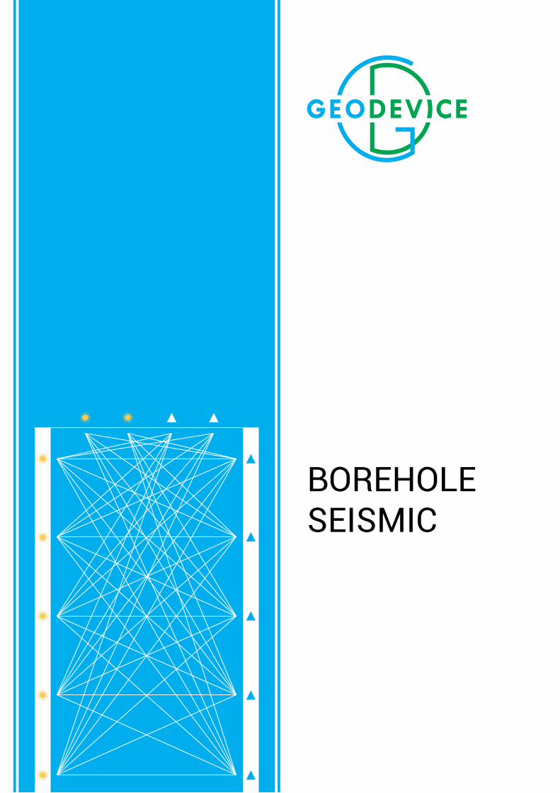
Geodevice LLC has vast experience in the development and production of equipment for performing all types of borehole seismic surveys. To date, we have a complete complex designed for solution of the most challenging tasks using the following borehole methods:
▪ Crosshole seismic testing (CST) is a method of detailed study of rocks properties in the interwell space with localization of various anomalies associated with changes in the physical and mechanical properties of rock mass.
▪ Different variations of vertical seismic profiling method, such as zero-offset, offset and reversed VSP. ▪ Borehole acoustic studies - methods of lithological stratification and calculation of elastic properties of
rocks near the wellbore in-situ.
4 5
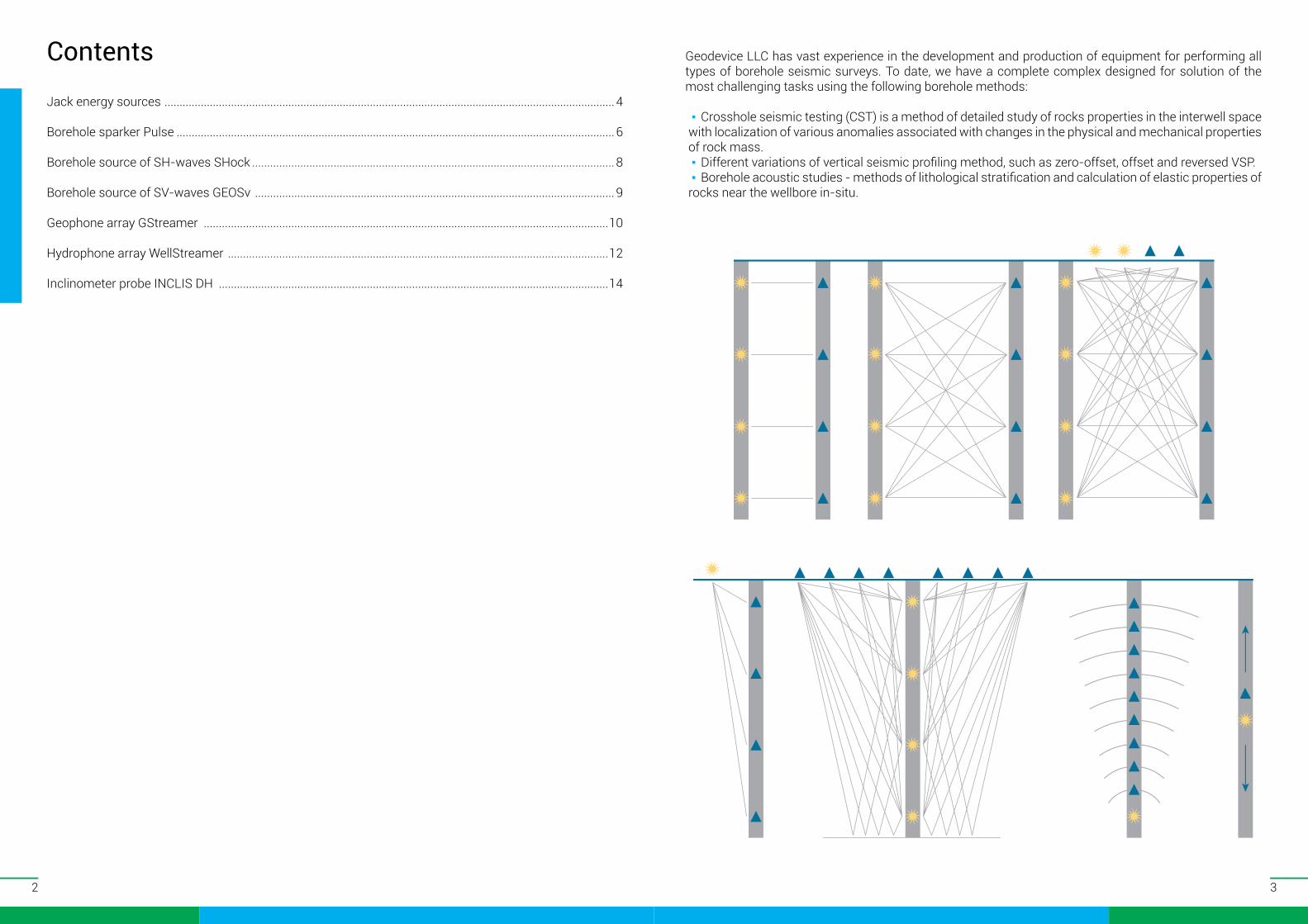
Jack energy sources
Jack energy sources ensure the operation of sparker and electrodynamic sources used in geophysical surveys in boreholes by methods of crosshole seismic testing (CST), vertical seismic profiling (VSP), vertical seismoacoustic profiling (VSaP) and others.
Jack design deploys a reliable thyristor key, that enables obtaining a really short high-voltage electric pulse. The energy source is operated from ас system with 110 / 220 V voltage.
MAIN features: ▪ High charging rate ▪ Capability to control power
consumption ▪ Remote control unit ▪ Portability
Jack Version 500 1200 2500HPOperating voltage 2-4 kVDischarger type thyristorTrigger mode external/repetitive/manualOperating energy 50-500 J 300-1200 J 300-2500 JCharge rate 500 J/s 500 J/s 1500 J/sMinimum period of operation at the minimum pulse energy 0.4 s 1.4 s 0.6 sMinimum period of operation at the maximum pulse energy 1.2 s 2.7 s 1.9 sParameters of supplying electric line 110 or 220 V, 50 HzPower consumption 1 kW 1 kW 1/2/3 kW
Overall dimensions 490×370×230 mm
540×410×270 mm
630×500×300 mm
Weight 18 kg 22 kg 34 kg
JackPadFunction remote control of JackMaximum length of communication line 100 mOverall dimensions 210×165×90 mm
Weight 1 kg
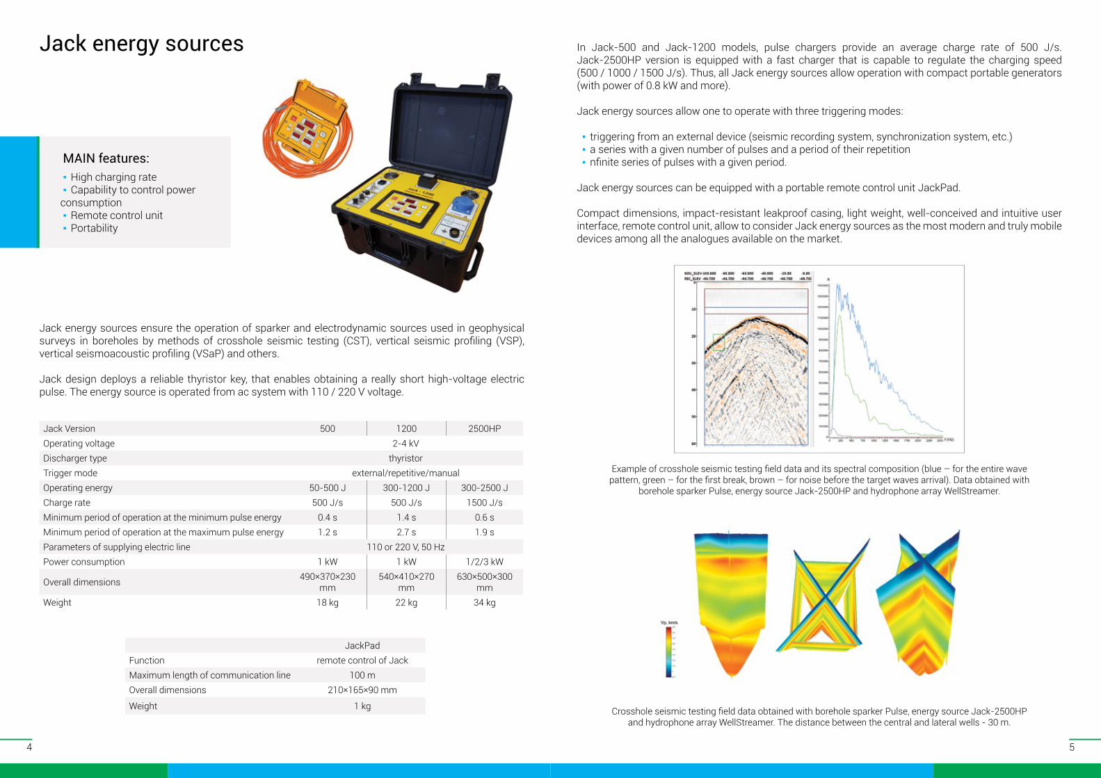
Example of сrosshole seismic testing field data and its spectral composition (blue – for the entire wave pattern, green – for the first break, brown – for noise before the target waves arrival). Data obtained with
borehole sparker Pulse, energy source Jack-2500HP and hydrophone array WellStreamer.
Crosshole seismic testing field data obtained with borehole sparker Pulse, energy source Jack-2500HP and hydrophone array WellStreamer. The distance between the central and lateral wells - 30 m.
In Jack-500 and Jack-1200 models, pulse chargers provide an average charge rate of 500 J/s. Jack-2500HP version is equipped with a fast charger that is capable to regulate the charging speed (500 / 1000 / 1500 J/s). Thus, all Jack energy sources allow operation with compact portable generators (with power of 0.8 kW and more).
Jack energy sources allow one to operate with three triggering modes:
▪ triggering from an external device (seismic recording system, synchronization system, etc.) ▪ a series with a given number of pulses and a period of their repetition ▪ nfinite series of pulses with a given period.
Jack energy sources can be equipped with a portable remote control unit JackPad.
Compact dimensions, impact-resistant leakproof casing, light weight, well-conceived and intuitive user interface, remote control unit, allow to consider Jack energy sources as the most modern and truly mobile devices among all the analogues available on the market.
6 7
Borehole sparker Pulse
Borehole sparker Pulse is utilized to generate pressure waves in water-filled boreholes while performing the operations via crosshole seismic testing (CST) and vertical seismic profiling (VSP) methods. The operation of the Pulse source is provided by the Jack energy sources. The design of the source provides easy replacement of wear electrode groups, what also allows to control the signature of the source by installing a group with a different number of electrodes.
The standard diameters of the containers are 36 / 60 / 80 mm, thus allowing operations in wells with diameters starting from 40 mm. It is important to understand that in order to provide a stable pulse of high energy and a significant operational life of the source, a sufficient volume of the container and the number of electrodes greater than 25 are necessary.
Pulse sources are shipped on geophysical reels equipped with high-voltage slip ring. Thus, one does not need to disconnect the source from an energy source during operations of winding / unwinding the cable.
MAIN features: ▪ Easily replaceable electrode group ▪ Can be used in wells with diameters
starting from 40 mm ▪ Reel with high-voltage slip ring
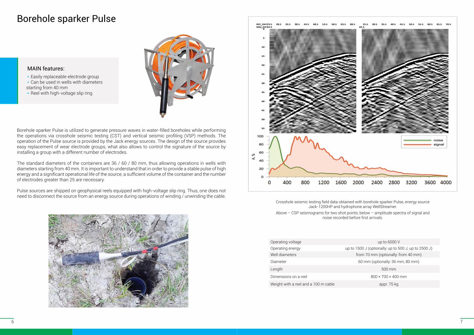
Crosshole seismic testing field data obtained with borehole sparker Pulse, energy source Jack-1200HP and hydrophone array WellStreamer.
Above – CSP seismograms for two shot points; below – amplitude spectra of signal and noise recorded before first arrivals.
Operating voltage up to 6000 VOperating energy up to 1500 J (optionally: up to 500 J, up to 2500 J)Well diameters from 70 mm (optionally: from 40 mm)
Diameter 60 mm (optionally: 36 mm, 80 mm)
Length 500 mm
Dimensions on a reel 800 × 700 × 400 mm
Weight with a reel and a 100 m cable appr. 75 kg
8 9
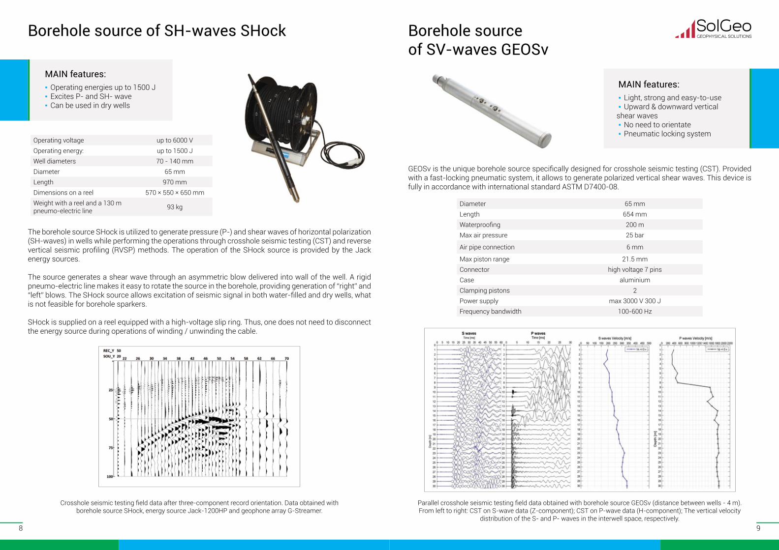
Crosshole seismic testing field data after three-component record orientation. Data obtained with borehole source SHock, energy source Jack-1200HP and geophone array G-Streamer.
Borehole source of SH-waves SHock
The borehole source SHock is utilized to generate pressure (P-) and shear waves of horizontal polarization (SH-waves) in wells while performing the operations through crosshole seismic testing (CST) and reverse vertical seismic profiling (RVSP) methods. The operation of the SHock source is provided by the Jack energy sources.
The source generates a shear wave through an asymmetric blow delivered into wall of the well. A rigid pneumo-electric line makes it easy to rotate the source in the borehole, providing generation of “right” and “left” blows. The SHock source allows excitation of seismic signal in both water-filled and dry wells, what is not feasible for borehole sparkers.
SHock is supplied on a reel equipped with a high-voltage slip ring. Thus, one does not need to disconnect the energy source during operations of winding / unwinding the cable.
MAIN features: ▪ Operating energies up to 1500 J ▪ Excites P- and SH- wave ▪ Can be used in dry wells
Operating voltage up to 6000 VOperating energy: up to 1500 JWell diameters 70 - 140 mmDiameter 65 mmLength 970 mmDimensions on a reel 570 × 550 × 650 mmWeight with a reel and a 130 m pneumo-electric line 93 kg
Borehole source of SV-waves GEOSv
MAIN features: ▪ Light, strong and easy-to-use ▪ Upward & downward vertical
shear waves ▪ No need to orientate ▪ Pneumatic locking system
GEOSv is the unique borehole source specifically designed for crosshole seismic testing (CST). Provided with a fast-locking pneumatic system, it allows to generate polarized vertical shear waves. This device is fully in accordance with international standard ASTM D7400-08.
Parallel crosshole seismic testing field data obtained with borehole source GEOSv (distance between wells - 4 m). From left to right: CST on S-wave data (Z-component); CST on P-wave data (H-component); The vertical velocity
distribution of the S- and P- waves in the interwell space, respectively.
Diameter 65 mmLength 654 mmWaterproofing 200 mMax air pressure 25 bar
Air pipe connection 6 mm
Max piston range 21.5 mmConnector high voltage 7 pinsCase aluminiumClamping pistons 2Power supply max 3000 V 300 JFrequency bandwidth 100-600 Hz
10 11
Geophone array GStreamer
Main features: ▪ ▪ Remote spring snapping ▪ ▪ Lowering the cable without load ▪ ▪ Compatibility with linear seismic
recording systems
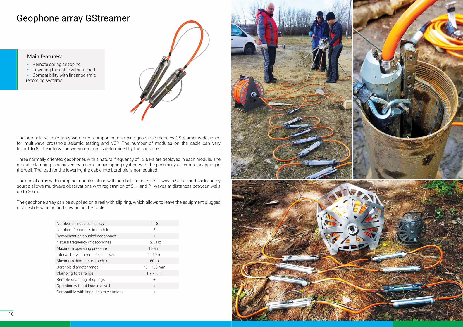
The borehole seismic array with three-component clamping geophone modules GStreamer is designed for multiwave crosshole seismic testing and VSP. The number of modules on the cable can vary from 1 to 8. The interval between modules is determined by the customer.
Three normally oriented geophones with a natural frequency of 12.5 Hz are deployed in each module. The module clamping is achieved by a semi-active spring system with the possibility of remote snapping in the well. The load for the lowering the cable into borehole is not required.
The use of array with clamping modules along with borehole source of SH-waves SHock and Jack energy source allows multiwave observations with registration of SH- and P- waves at distances between wells up to 30 m.
The geophone array can be supplied on a reel with slip ring, which allows to leave the equipment plugged into it while winding and unwinding the cable.
Number of modules in array 1 - 8Number of channels in module 3Compensation coupled geophones +Natural frequency of geophones 12.5 HzMaximum operating pressure 15 atmInterval between modules in array 1 : 10 mMaximum diameter of module 60 mBorehole diameter range 70 - 150 mmClamping force range 1:7 - 1:11Remote snapping of springs +Operation without load in a well +Compatible with linear seismic stations +
12 13
Hydrophone array WellStreamer
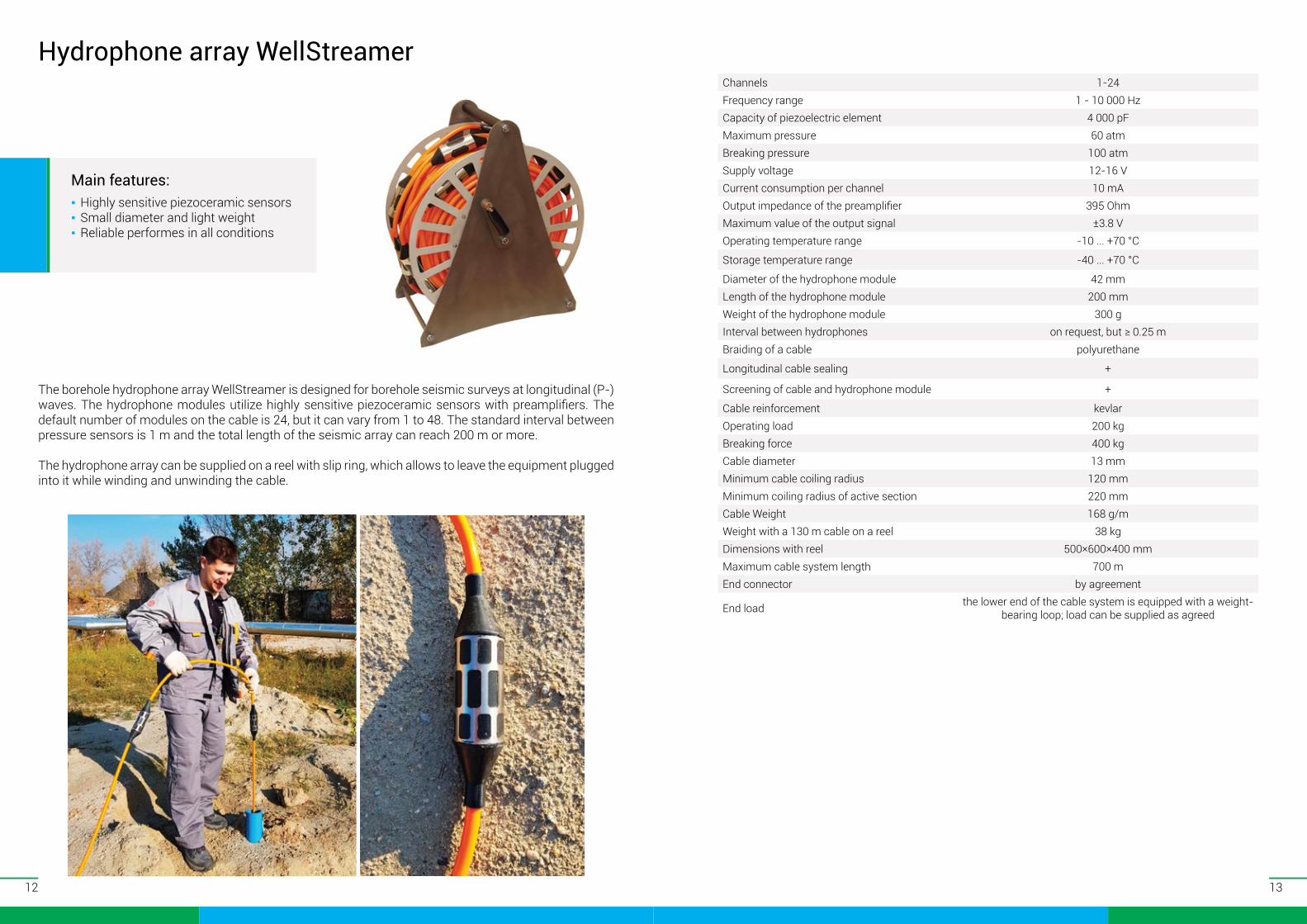
The borehole hydrophone array WellStreamer is designed for borehole seismic surveys at longitudinal (P-) waves. The hydrophone modules utilize highly sensitive piezoceramic sensors with preamplifiers. The default number of modules on the cable is 24, but it can vary from 1 to 48. The standard interval between pressure sensors is 1 m and the total length of the seismic array can reach 200 m or more.
The hydrophone array can be supplied on a reel with slip ring, which allows to leave the equipment plugged into it while winding and unwinding the cable.
Main features: ▪ Highly sensitive piezoceramic sensors ▪ Small diameter and light weight ▪ Reliable performes in all conditions
Сhannels 1-24Frequency range 1 - 10 000 HzCapacity of piezoelectric element 4 000 pFMaximum pressure 60 atmBreaking pressure 100 atmSupply voltage 12-16 VCurrent consumption per channel 10 mAOutput impedance of the preamplifier 395 OhmMaximum value of the output signal ±3.8 VOperating temperature range -10 ... +70 °С
Storage temperature range -40 ... +70 °С
Diameter of the hydrophone module 42 mmLength of the hydrophone module 200 mmWeight of the hydrophone module 300 gInterval between hydrophones on request, but ≥ 0.25 mBraiding of a cable polyurethane
Longitudinal cable sealing +
Screening of cable and hydrophone module +
Cable reinforcement kevlarOperating load 200 kgBreaking force 400 kgCable diameter 13 mmMinimum cable coiling radius 120 mmMinimum coiling radius of active section 220 mmCable Weight 168 g/mWeight with a 130 m cable on a reel 38 kgDimensions with reel 500×600×400 mmMaximum cable system length 700 mEnd connector by agreement
End load the lower end of the cable system is equipped with a weight-bearing loop; load can be supplied as agreed
14
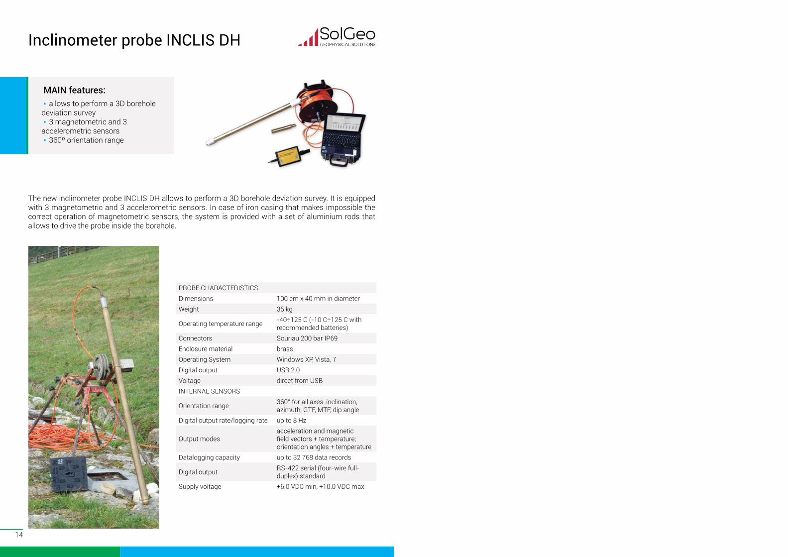
Inclinometer probe INCLIS DH
The new inclinometer probe INCLIS DH allows to perform a 3D borehole deviation survey. It is equipped with 3 magnetometric and 3 accelerometric sensors. In case of iron casing that makes impossible the correct operation of magnetometric sensors, the system is provided with a set of aluminium rods that allows to drive the probe inside the borehole.
MAIN features: ▪ allows to perform a 3D borehole
deviation survey ▪ 3 magnetometric and 3
accelerometric sensors ▪ 360º orientation range
PROBE CHARACTERISTICSDimensions 100 cm x 40 mm in diameterWeight 35 kg
Operating temperature range -40÷125 C (-10 C÷125 C with recommended batteries)
Connectors Souriau 200 bar IP69Enclosure material brassOperating System Windows XP, Vista, 7Digital output USB 2.0Voltage direct from USBINTERNAL SENSORS
Orientation range 360° for all axes: inclination, azimuth, GTF, MTF, dip angle
Digital output rate/logging rate up to 8 Hz
Output modesacceleration and magnetic field vectors + temperature; orientation angles + temperature
Datalogging capacity up to 32 768 data records
Digital output RS-422 serial (four-wire full-duplex) standard
Supply voltage +6.0 VDC min, +10.0 VDC max
geo-device.com
Designs, manufactures, supports and supplies Equipment & Software for geophysical surveys:
▪ Seismic ▪ Geoelectric & Electromagnetic ▪ Magnetic ▪ Gamma radiation detection
Advanced options: ▪ Rentals ▪ Field demonstrations ▪ Test surveys ▪ Projects startup ▪ Training courses
Related Documents