Modified Booth Multiplier with FIR Filter Seminar by Melisha Monteiro 1 st year M.Tech EC Usn : 4CB14LEL07 Department of ECE, CEC Benjanapadavu 1

Welcome message from author
This document is posted to help you gain knowledge. Please leave a comment to let me know what you think about it! Share it to your friends and learn new things together.
Transcript

1
Modified Booth Multiplier with FIR Filter
Seminar by Melisha Monteiro
1st year M.Tech EC
Usn : 4CB14LEL07
Department of ECE, CEC Benjanapadavu
2Department of ECE, CEC Benjanapadavu
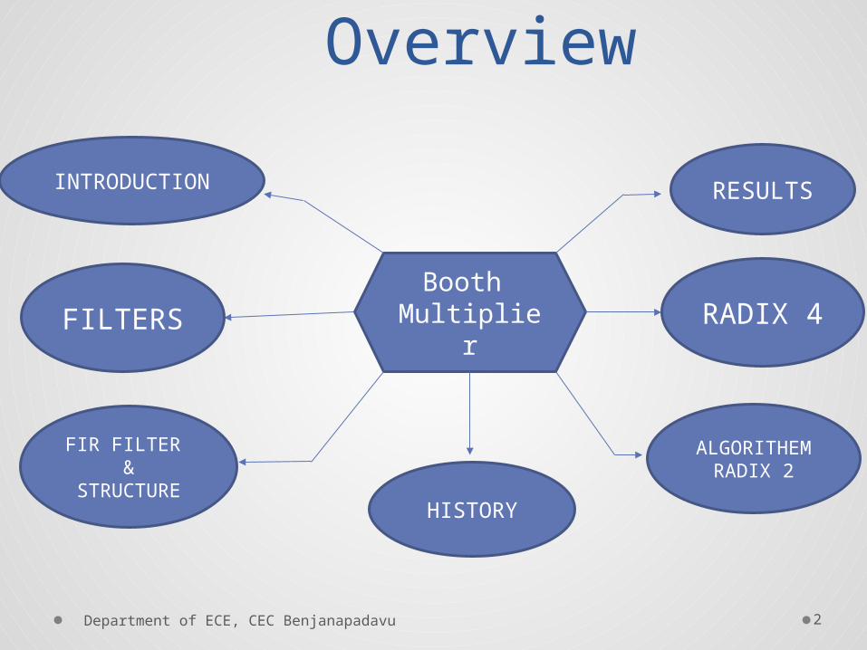
Overview
Booth Multiplier
INTRODUCTION
FILTERS
FIR FILTER &
STRUCTUREHISTORY
ALGORITHEM RADIX 2
RADIX 4
RESULTS

3Department of ECE, CEC Benjanapadavu
INTRODUCTION

4
INTRODUCTION Multipliers are key components of many high performance systems such as
FIR filters, Microprocessor, digital signal processors, etc.
A system’s performance is generally determined by the performance of the
Multiplier.
With advances in technology, many researchers have tried and are trying to
design multipliers which offer either of the following design targets
i. High speed
ii. Low power consumption
iii. Regularity of layout
iv. Less area.
• .Department of ECE, CEC Benjanapadavu
5
INTRODUCTION Why we use Filters ??
The filter is used to remove some unwanted component or feature from a signal there by improving the quality of signal.
Functin Of Filter
To modify the frequency spectrum of a signal and to model the input output relationship of a system .
Application Of Filter
Signal processing and communication system in applications like noise reduction, echo cancellation, image enhancement, speech and waveform synthesis etc.
Department of ECE, CEC Benjanapadavu
6Department of ECE, CEC Benjanapadavu
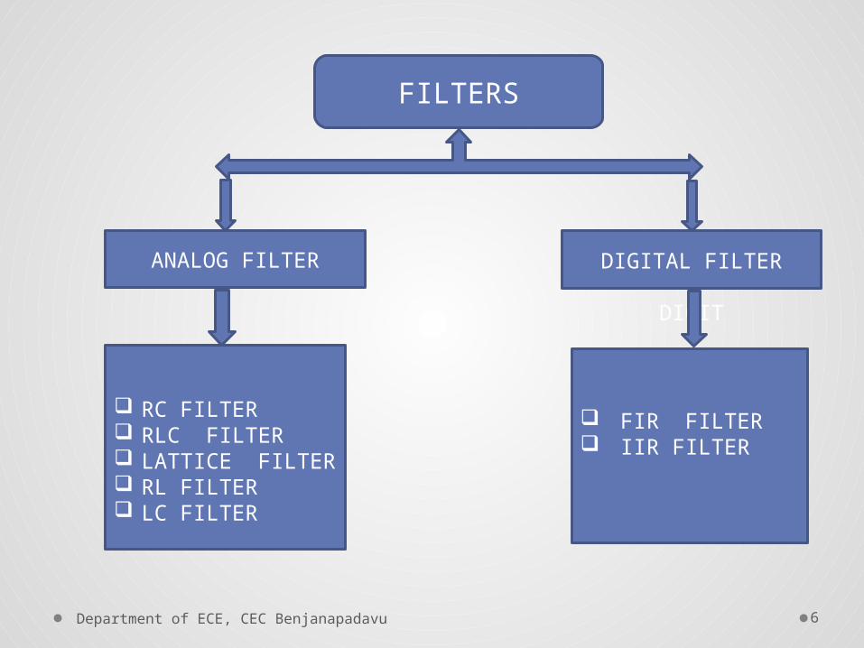
FILTERS
ANALOG FILTER DIGITAL FILTER
DIGIT
RC FILTER RLC FILTER LATTICE FILTER RL FILTER LC FILTER
FIR FILTER IIR FILTER
7
FIR FILTER FIR filter and IIR filter are two types of Digital filter.
FIR filter mostly prefer over IIR filter due to its linear phase
characteristics, low coefficient sensitivity, guarantee stability.
Multiplication and addition occurs frequently in ‘Finite
Impulse Response’ (FIR)
FIR filters design implementation consist a large number of
multiplications, which leads to excessive area and power
consumption
Department of ECE, CEC Benjanapadavu

8
FIR FILTER• The input- output relationship of FIR filter is given by
y(n) =
• x[n] and y [n] are the filter input and filter output
respectively
• a(k) ( k = 0,1,2,3……N-1) are the impulse response
coefficients of the filter.
• N is the filter length that is number of coefficients.
Department of ECE, CEC Benjanapadavu

9
STRUCTURE OF FIR FILTER
Department of ECE, CEC Benjanapadavu

10Department of ECE, CEC Benjanapadavu
There are many types of multipliers. For example
Array multiplier
Booth multiplier
Serial multiplier
Shift and Add multiplier
Wallace tree multiplier
Baugh Woolley multiplier
Braun multiplier

11
HISTORY
Department of ECE, CEC Benjanapadavu
The algorithm was invented by
Andrew Donald Booth in 1951
while doing research on
crystallography in London.
Department of ECE, CEC Benjanapadavu
12
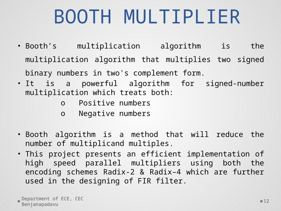
BOOTH MULTIPLIER• Booth’s multiplication algorithm is the multiplication algorithm that
multiplies two signed binary numbers in two's complement form.• It is a powerful algorithm for signed-number multiplication which
treats both:o Positive numberso Negative numbers
• Booth algorithm is a method that will reduce the number of multiplicand multiples.
• This project presents an efficient implementation of high speed parallel multipliers using both the encoding schemes Radix-2 & Radix–4 which are further used in the designing of FIR filter.
14
THE ALGORITHEM
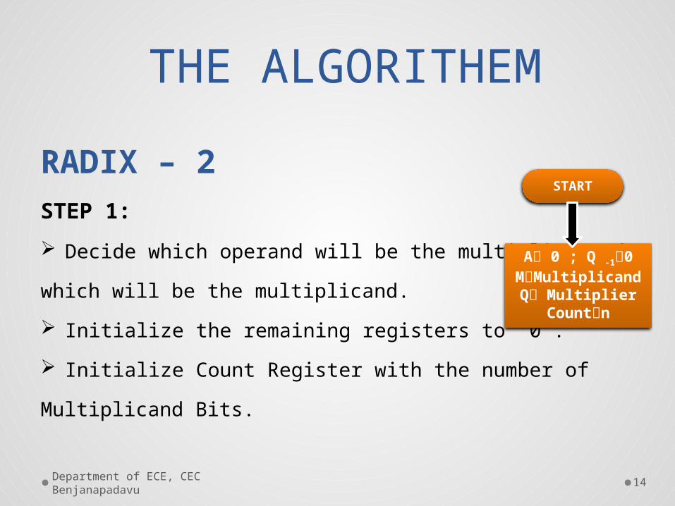
RADIX – 2
STEP 1:
Decide which operand will be the multiplier and
which will be the multiplicand.
Initialize the remaining registers to ‘0’.
Initialize Count Register with the number of
Multiplicand Bits.
Department of ECE, CEC Benjanapadavu
START
A 0 ; Q -10MMultiplicand
Q MultiplierCountn

15
Possible Arithmetic Actions
STEP 2 :
00 no arithmetic operation
01 add multiplicand to left half of
product
10 subtract multiplicand from left
half of product
11 no arithmetic operation
Department of ECE, CEC Benjanapadavu
START
A 0 ; Q -10MMultiplicand
Q MultiplierCountn
Q 0 ,Q
-1
AA-M A A+M=11=00
Arithmetic Shift right
A, Q, Q-1
Count Count -1
16
THE ALGORITHEMSTEP 3:
Perform an arithmetic right shift (ASR) on the entire product.
STEP 4 : When Count register is not ‘0’ then continue the
multiplication. If Count register is ‘0’ then END the Algorithm.
Department of ECE, CEC Benjanapadavu

17Department of ECE, CEC Benjanapadavu
START
A 0 ; Q -10MMultiplicand
Q MultiplierCountn
Q 0 ,Q
-1
AA-M A A+M
=01
=11=00
=10
Arithmetic Shift right
A, Q, Q-1
Count Count -1
Count=0?
END

18Department of ECE, CEC Benjanapadavu
EXAMPLE(7) 0111 M (Multiplicand)
(3) 0011 Q (Multiplier)
Take 2’s compliment of Multiplicand (-7) 1001 -M
0 A 0 Q-1
Count=no. of bits4

19Department of ECE, CEC Benjanapadavu
STEP A Q Q-1 Action Count
1 0 0 0 0 0 0 1 1 0 Initial 4
22
1 0 0 11 1 0 0
0 0 1 11 0 0 1
01
AA-MShift 3
3 1 1 1 0 0 1 0 0 1 Shift 2
44
0 1 0 10 0 1 0
0 1 0 01 0 1 0
10
AA+MShift 1
5 0 0 0 1 0 1 0 1 0 Shift 0

Department of ECE, CEC Benjanapadavu
20
RADIX 4 The shortcomings of Radix-2 can get rid by Radix-4 in
which it handle more than one bit of multiplier in each
cycle.
The modified Booth's algorithm starts by appending a
zero to right of LSB of multiplier.
Department of ECE, CEC Benjanapadavu
21
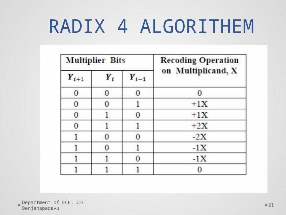
RADIX 4 ALGORITHEM

22
Multiply by zero means the multiplicand is multiplied by ‘0’.
Multiply by ‘1’ means the product still remains the same as the
multiplicand value.
Multiply by ‘-1’means that the product is the two’s
complement form of the number.
Multiply by ‘-2’ is to shift left one bit the two’s complement
of the multiplicand value.
multiply by ‘2’ means just shift left the multiplicand by one
place.
Department of ECE, CEC Benjanapadavu
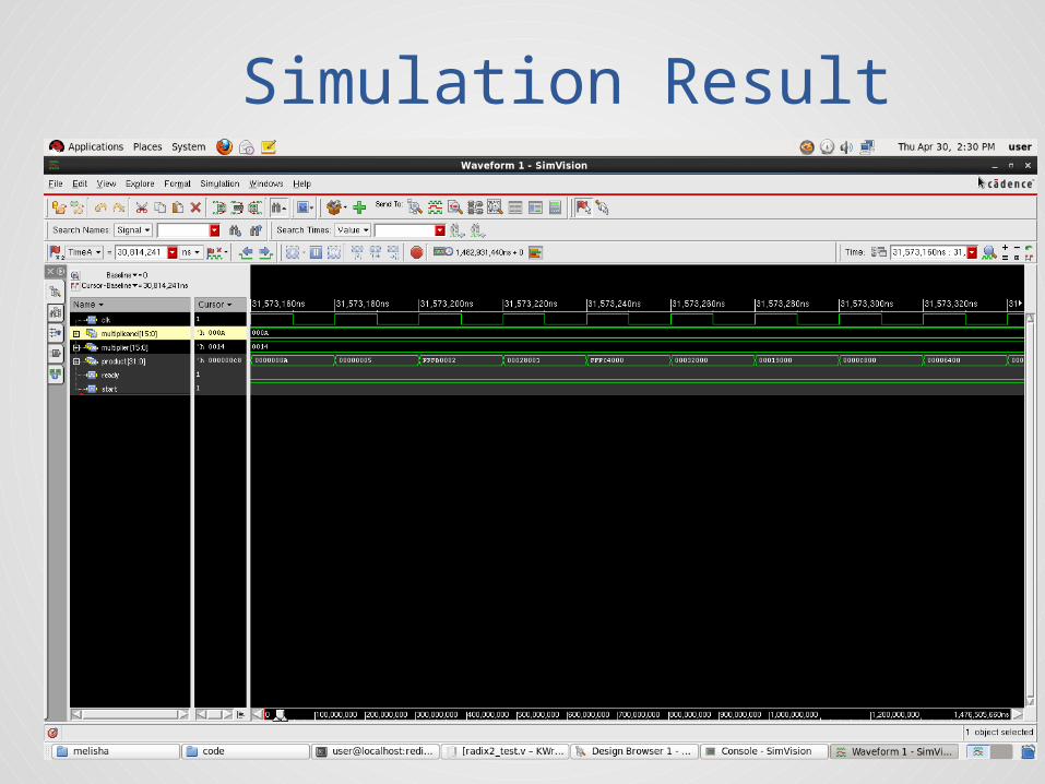
Simulation Result

24
Simulation Result
Department of ECE, CEC Benjanapadavu

25Department of ECE, CEC Benjanapadavu
[1] Ankit Jairath, Sunil Kumar Shah, Amit Jain – “Design & implementation
of
FPGA based digital filters”, Journal of IJARCET, ISSN: 2278-1323, Vol. 1,
Issue 7, Sept.2012
[2] E. Ifeachor and B. Jervis, “Finite impulse response (FIR) filter design” in
Digital Signal Processing: A Practical Approach, 2nd ed., D. Kindersley,
Ed. South Asia: Pearson Education, 2002, pp. 342-440
[3] B. Rashidi, B. Rashidi and M. Pourormazd, “Design and Implementation
of
Low Power Digital FIR Filter based on low power multipliers and adders
on Xilinx FPGA”, International Conference on Electronics Computer
Technology, 2011, pp.18- 22.
REFRENCES

Department of ECE, CEC Benjanapadavu
26
THANK YOU