ﺍﻟﻌﻤﻠﻴﺔ ﺍﻟﺘﺠﺎﺭﺏ Programming Embedded Systems Microcontroller You Can Practice Microcontroller Programming Easily Now! Tuesday, December 15, 2009

Welcome message from author
This document is posted to help you gain knowledge. Please leave a comment to let me know what you think about it! Share it to your friends and learn new things together.
Transcript

التجارب العملية
Programming
Embedded Systems Microcontroller
You Can Practice Microcontroller Programming Easily Now!
Tuesday, December 15, 2009

2
General Introduction about this course
Assembly
AVRBasicBascom-AVR
Proteus
Development Board
50

Practical Class 1 Programming Microcontrollers
Faculty of Electrical and Electronic Eng. 3 Automatic Control & Automation Dept.
Bascom-AVR Bascom-AVR Compiler
Bascom-AVR
•
• _
4
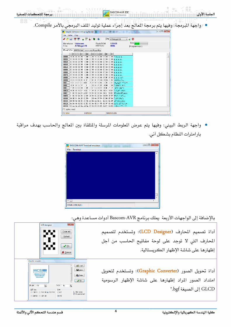
• Compile
•
Bascom-AVR
LCD Designer
Graphic Converter
GLCD*.bgf
Practical Class 1 Programming Microcontrollers
Faculty of Electrical and Electronic Eng. 5 Automatic Control & Automation Dept.
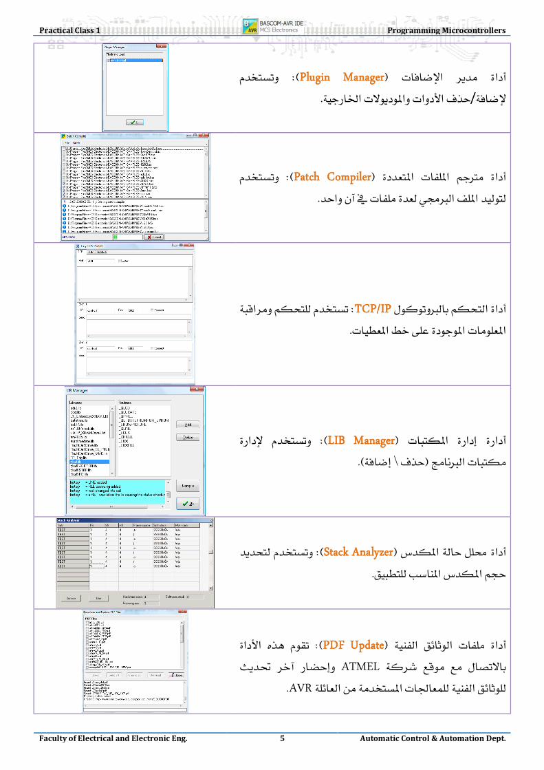
Plugin Manager /
Patch Compiler
TCP/IP
LIB Manager \
Stack Analyzer
PDF Update ATMEL
AVR

6
Export to RTF fileWORD
Export to HTML.
Bascom-AVR 1. . 2
3 Syntax CheckProgram
4
5- Sub Routines
They are sub programs or sub procedures, call from the main program
4- Main Program
Contains all executive instructions such as: Mathematical Instruction.
3- Variables
Dimension all required variables.
2- Configuration
Configuration commands initialize the hardware to the desired state.
1- Directives
Directives are special instructions for the compiler. They can override a setting from the IDE.
، LOOPيتوقع وجود تعليمة .DOهذا صحيح ألنه يوجد

Practical Class 1 Programming Microcontrollers
Faculty of Electrical and Electronic Eng. 7 Automatic Control & Automation Dept.
5 Compile Program
6 Send to programmerProgram
Bascom-AVR
ت لعتلا فينصت جم ربلا ة ب يف ةيجمربلا
Bascom-AVR نع دیز ت لعتلا دد
ةميلعت350
خيراتلاو ت قوتلا ةيطرشلاةئيهت اتالیوحتلاينمزلا ري أتلاتور لو و
1-WIRE
عم لماعتلاا افلمل ت
تاهيجوتلا
اش ا ةش إل اهظ رلا ة موسر
اش ا ةش إل اهظ رةيلات س ركلا
تور اI2C لو و دإل ا او ل إل ارخ ج
ا لحل اق لاو ت فق ز ا مل ؤ ارش تتور لو و
PS2ا اقمل اعط ت
عم لماعتلاا ةر ا جلاعمل مكحتلا
ة فرحملا لسالسلاتور لو و
SPI
تور لو وRS232
دعب نع مكحتلا
ةيباسحلاتاثلثملاو
تور لو وTCP/IP
ISIS Proteus ISIS Proteus Simulation
8
Proteus
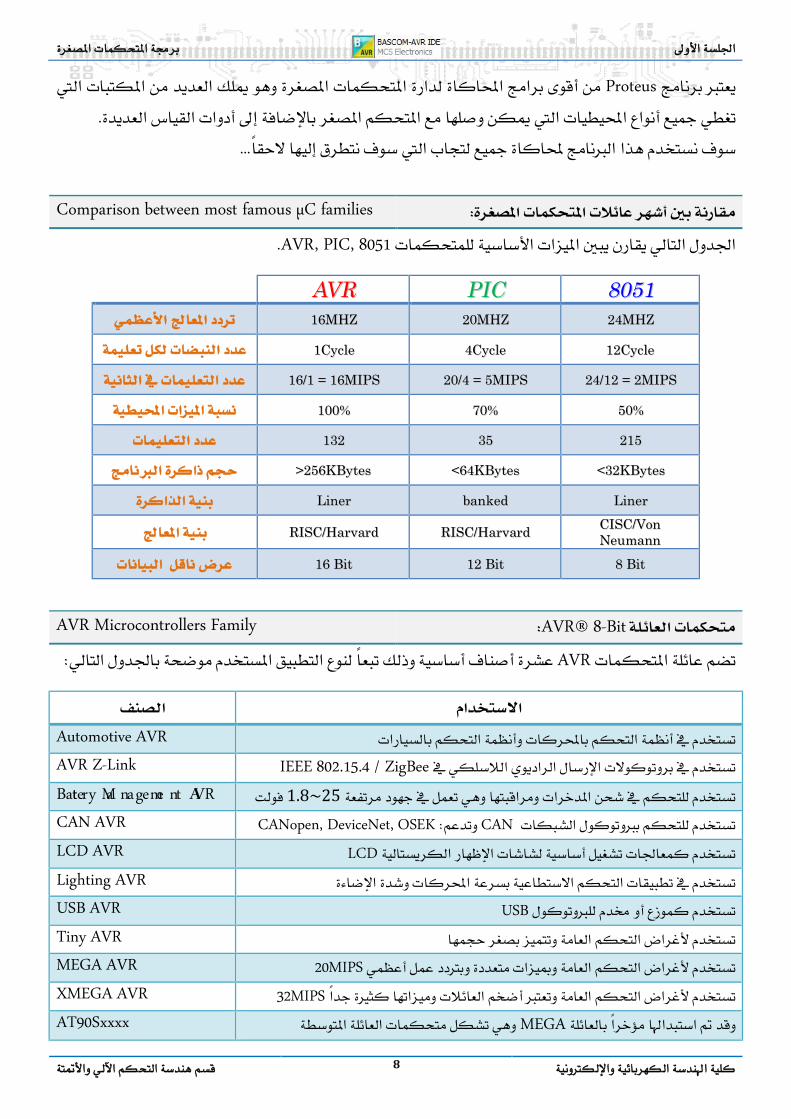
Comparison between most famous µC families AVR, PIC, 8051
AAVVRR PPIICC 88005511 1166MMHHZZ 2200MMHHZZ 2244MMHHZZ
11CCyyccllee 44CCyyccllee 1122CCyyccllee
1166//11 == 1166MMIIPPSS 2200//44 == 55MMIIPPSS 2244//1122 == 22MMIIPPSS
110000%% 7700%% 5500%%
113322 3355 221155
>>225566KKBByytteess <<6644KKBByytteess <<3322KKBByytteess
LLiinneerr bbaannkkeedd LLiinneerr
RRIISSCC//HHaarrvvaarrdd RRIISSCC//HHaarrvvaarrdd CCIISSCC//VVoonn NNeeuummaannnn
1166 BBiitt 1122 BBiitt 88 BBiitt
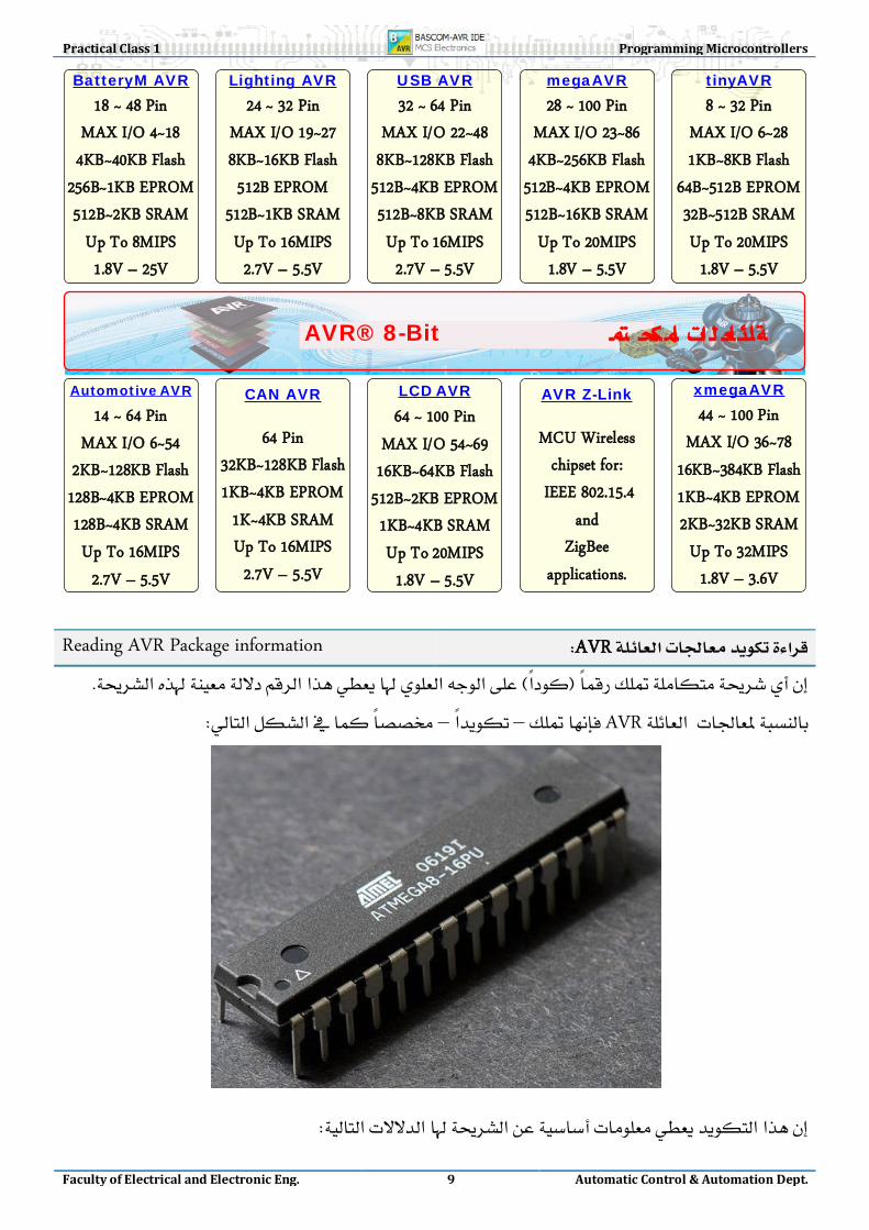
AVR® 8-Bit AVR Microcontrollers Family
AVR
Automotive AVR
IEEE 802.15.4 / ZigBee AVR Z-Link 1.8~25 Battery Ma nageme nt AVR
CANCANopen, DeviceNet, OSEK CAN AVR LCD LCD AVR
Lighting AVR USB USB AVR
Tiny AVR 20MIPS MEGA AVR
32MIPS XMEGA AVR MEGA AT90Sxxxx
Practical Class 1 Programming Microcontrollers
Faculty of Electrical and Electronic Eng. 9 Automatic Control & Automation Dept.
AutomotiveAVR
14 ~ 64 PinMAX I/O 6~54
2KB~128KB Flash128B~4KB EPROM128B~4KB SRAMUp To 16MIPS
2.7V – 5.5V
AVR Z-Link
MCU Wireless chipset for:
IEEE 802.15.4and
ZigBee applications.
BatteryM AVR18 ~ 48 Pin
MAX I/O 4~184KB~40KB Flash
256B~1KB EPROM512B~2KB SRAM
Up To 8MIPS1.8V – 25V
CAN AVR
64 Pin32KB~128KB Flash1KB~4KB EPROM
1K~4KB SRAMUp To 16MIPS
2.7V – 5.5V
LCD AVR64 ~ 100 Pin
MAX I/O 54~6916KB~64KB Flash
512B~2KB EPROM1KB~4KB SRAMUp To 20MIPS
1.8V – 5.5V
Lighting AVR24 ~ 32 Pin
MAX I/O 19~278KB~16KB Flash512B EPROM
512B~1KB SRAMUp To 16MIPS
2.7V – 5.5V
USB AVR32 ~ 64 Pin
MAX I/O 22~488KB~128KB Flash
512B~4KB EPROM512B~8KB SRAMUp To 16MIPS
2.7V – 5.5V
megaAVR28 ~ 100 Pin
MAX I/O 23~864KB~256KB Flash
512B~4KB EPROM512B~16KB SRAM
Up To 20MIPS1.8V – 5.5V
tinyAVR8 ~ 32 Pin
MAX I/O 6~281KB~8KB Flash
64B~512B EPROM32B~512B SRAMUp To 20MIPS
1.8V – 5.5V
xmegaAVR44 ~ 100 Pin
MAX I/O 36~7816KB~384KB Flash1KB~4KB EPROM2KB~32KB SRAM
Up To 32MIPS1.8V – 3.6V
AVR® 8-Bit
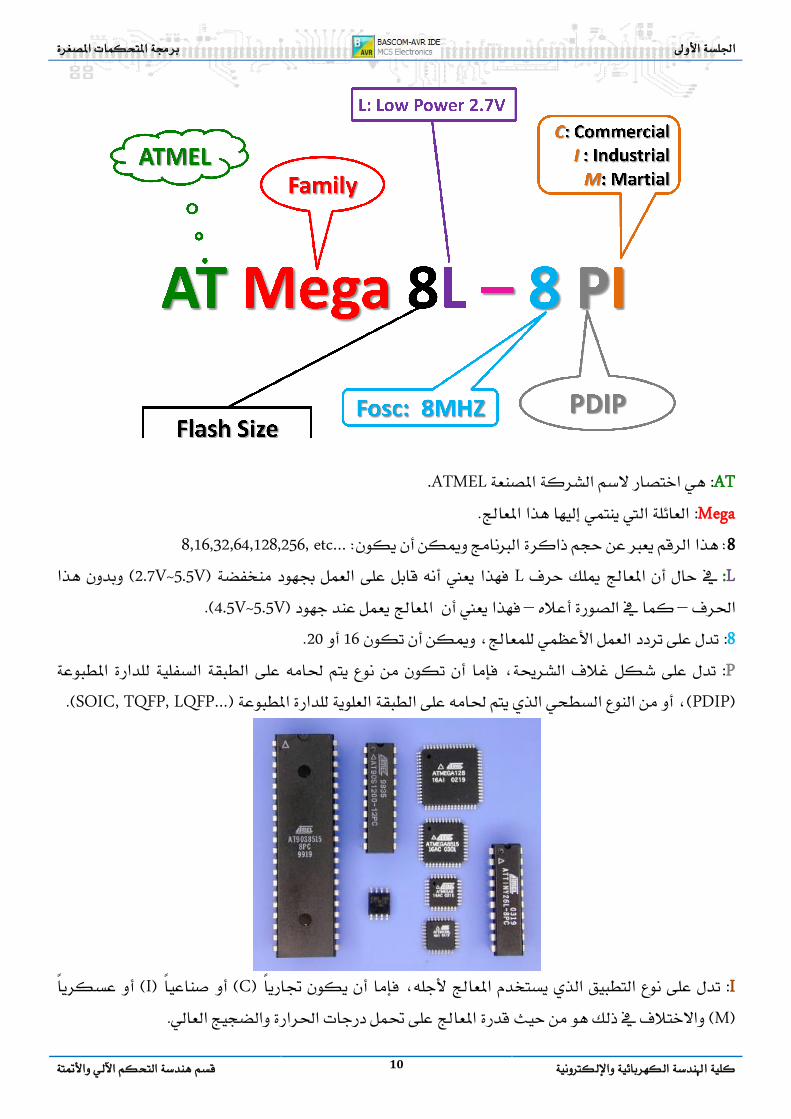
AVR Reading AVR Package information
AVR––
10
AT :ATMEL. Mega :
88,16,32,64,128,256, etc… L :L 2.7V~5.5V
––4.5V~5.5V 8 :1620 P : PDIPSOIC, TQFP, LQFP…
I : C IM

Practical Class 1 Programming Microcontrollers
Faculty of Electrical and Electronic Eng. 11 Automatic Control & Automation Dept.
Reading Datasheet of ICs
–Datasheet –
Bascom-AVR Assembly
––
ATmega128 Reading Datasheet of ATmega128
• Features 8-bit High-performance, Low-power AVR® 8-bit Microcontroller
• RISC 133 –
32 x 8 – + – – 16 16 MHz –
• Advanced RISC Architecture. – 133 Powerful Instructions Most Single Clock Cycle. – 32 x 8 General Purpose Working Registers + Peripheral
Control Registers – Fully Static Operation – Up to 16 MIPS Throughput at 16 MHz – On-chip 2-cycle Multiplier
• –128KB
10,000 – –4KB EEPROM
100,000 –4KB SRAM –64KB – –SPI
• Nonvolatile Program and Data Memories – 128K Bytes of In-System Reprogrammable Flash
Endurance: 10,000 Write/Erase Cycles – Optional Boot Code Section with Independent Lock Bits
In-System Programming by On-chip Boot Program - True Read-While-Write Operation
– 4K Bytes EEPROM Endurance: 100,000 Write/Erase Cycles
– 4K Bytes Internal SRAM – Up to 64K Bytes Optional External Memory Space – Programming Lock for Software Security – SPI Interface for In-System Programming
• JTAG – –Debug –
• JTAG (IEEE std. 1149.1 Compliant) Interface – Boundary-scan Capabilities According to the JTAG Standard – Extensive On-chip Debug Support –Programming of Flash, EEPROM, Fuses and Lock Bits
through the JTAG Interface
12
• –/8-bit –/16-bit
– –PWM8-bit –PWM16-bit
216 –/10-bit –I2C –USARTs –SPI/ – –
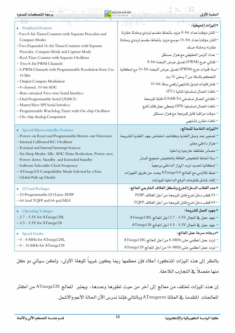
• Peripheral Features –Two 8-bit Timer/Counters with Separate Prescalers and
Compare Modes –Two Expanded 16-bit Timer/Counters with Separate
Prescaler, Compare Mode and Capture Mode – Real Time Counter with Separate Oscillator – Two 8-bit PWM Channels – 6 PWM Channels with Programmable Resolution from 2 to
16 Bits – Output Compare Modulator – 8-channel, 10-bit ADC – Byte-oriented Two-wire Serial Interface – Dual Programmable Serial USARTs – Master/Slave SPI Serial Interface – Programmable Watchdog Timer with On-chip Oscillator – On-chip Analog Comparator
• – – – – – –ATmega103 –
• Special Microcontroller Features – Power-on Reset and Programmable Brown-out Detection – Internal Calibrated RC Oscillator – External and Internal Interrupt Sources – Six Sleep Modes: Idle, ADC Noise Reduction, Power-save,
Power-down, Standby, and Extended Standby – Software Selectable Clock Frequency – ATmega103 Compatibility Mode Selected by a Fuse – Global Pull-up Disable
• / –53/PDIP –64/TQFP
• I/O and Packages – 53 Programmable I/O Lines-PDIP – 64-lead TQFP and 64-pad MLF
• –2.7 - 5.5V ATmega128L –4.5 - 5.5V ATmega128
• Operating Voltages – 2.7 - 5.5V for ATmega128L – 4.5 - 5.5V for ATmega128
• –8-MHz ATmega128L –16-MHz ATmega128
• Speed Grades – 0 - 8 MHz for ATmega128L – 0 - 16 MHz for ATmega128
ATmega128 ATmegaxxx .
Practical Class 1 Programming Microcontrollers
Faculty of Electrical and Electronic Eng. 13 Automatic Control & Automation Dept.
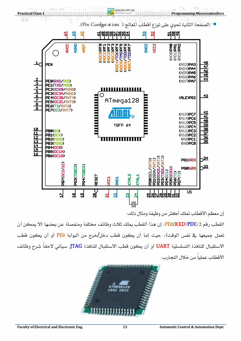
• Pin Configur at ions
2 PE0(RXD/PDI) / PE0 UART JTAG
14
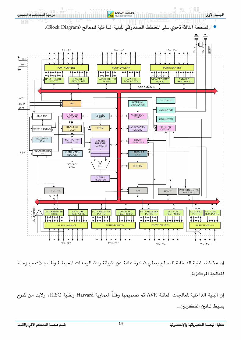
• Block Diagram
AVR Harvard RISC

Practical Class 1 Programming Microcontrollers
Faculty of Electrical and Electronic Eng. 15 Automatic Control & Automation Dept.
Standard Systems Design
HarvardVon Neumann
Von-Neumann
• • • •
Harvard
Methods Architecture Systems Design
CISC :Complex Instruction Set Computer )150 ~ 1500 Instruction(. RISC :Reduced Instruction Set Computer )30 ~ 130 Instruction(. MISC :Minimum Instruction Set Computer )15 ~ 30 Instruction(.
CISC

16
INTEL &AMD
RISC
RISC
MicrocontrollersDSPs
µA
MISC
Practical Class 1 Programming Microcontrollers
Faculty of Electrical and Electronic Eng. 17 Automatic Control & Automation Dept.
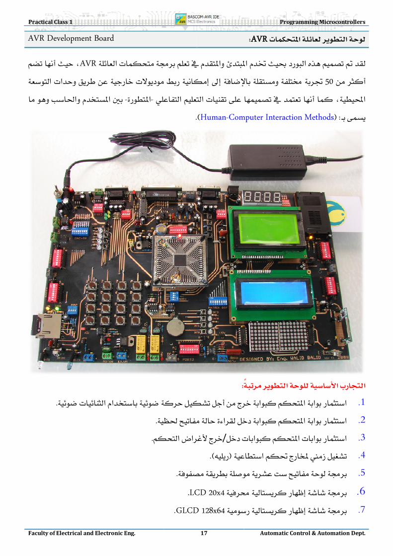
AVR AVR Development Board
AVR50
-- Human-Computer Interaction Methods
1.
2.
3. /
4.
5.
6. LCD 20x4.
7. GLCD 128x64

18
8.
9. DTMF
10.
11.
12. RC5, RC5-Extended.
13. RC5, RC5-Extended .
14. 0 – 9
15. 0 – 9999.
16. UART1RS232
17. UART2
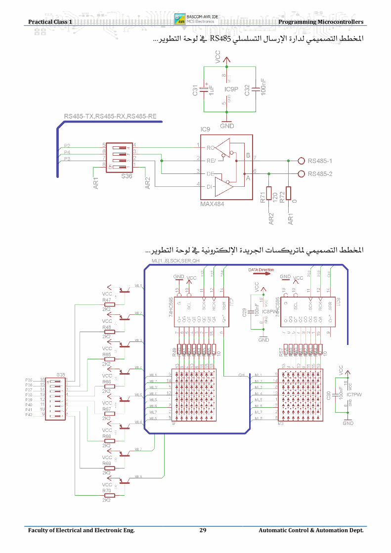
18. RS485
19.
20.
21.
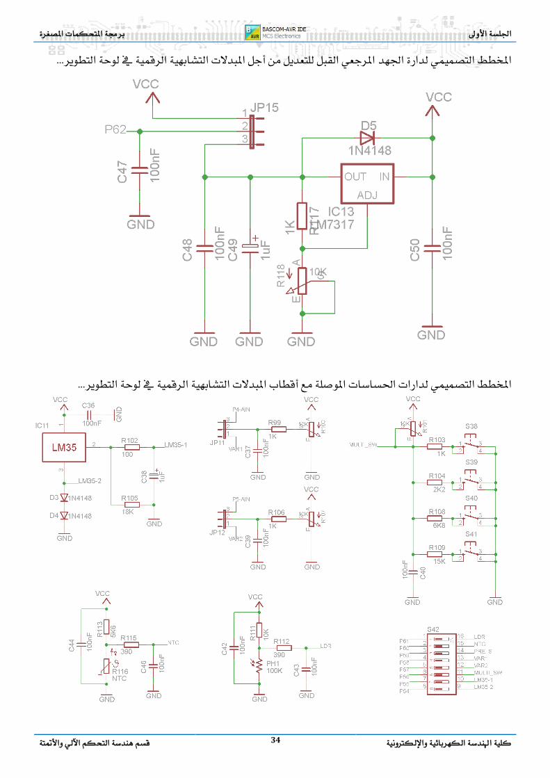
22. -45⁰C ~ +100⁰CLM35DZ.
23. NTCADC
24.
25. ADC.
26.
27.
28.
29. PWM
30.
31.
32.
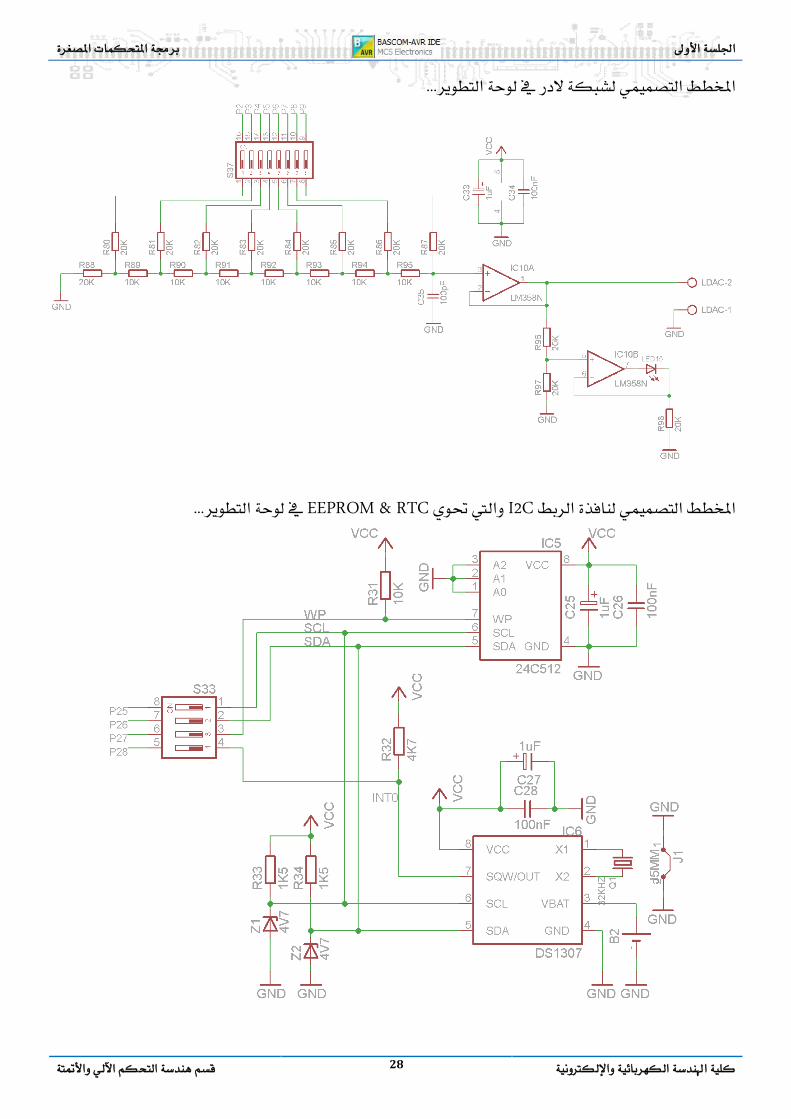
33. LadderDAC
34. DAC
Practical Class 1 Programming Microcontrollers
Faculty of Electrical and Electronic Eng. 19 Automatic Control & Automation Dept.
35.
36. RTC
37. EEPROM.
38.
39. Overflow, Compare & Capture modes
40. MMC
41. Smart Card
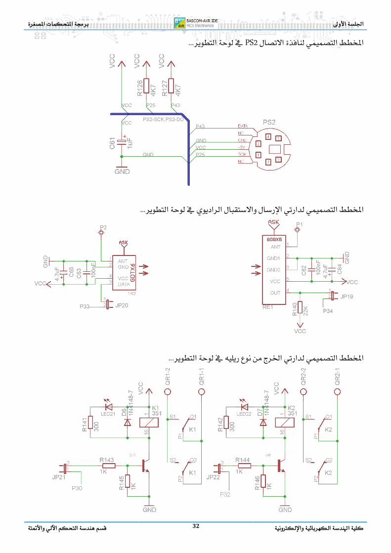
42. PS2
43. PS2
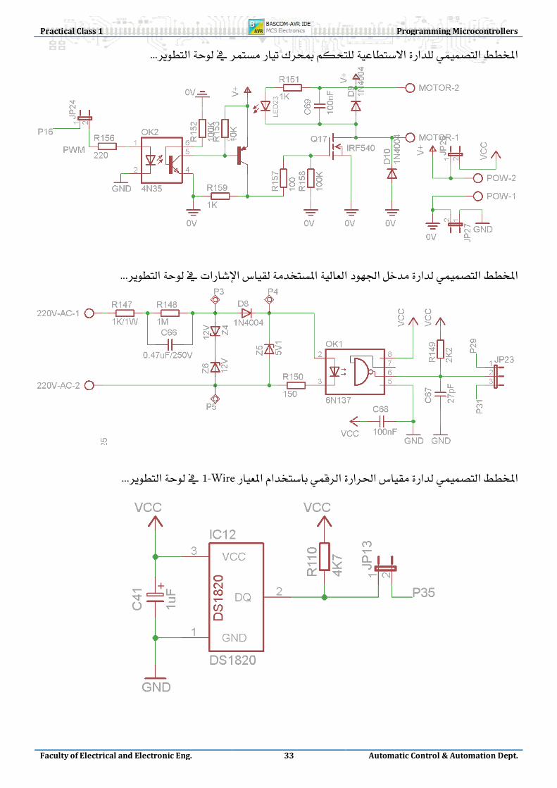
44. 1-WireDS1821
45. LED-Matrix Displays
46. RS232USART
47. EEPROM
48.
49.
50.
51.
52. JTAG.
53.
54. PCBsESD, EMC & EMI
55. MultitaskingRTS
56.
57. SPI
20
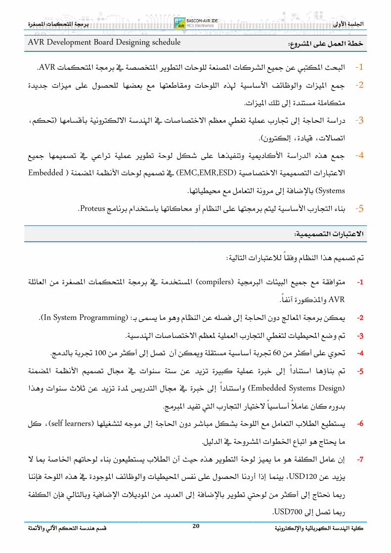
AVR Development Board Designing schedule
1- AVR
2-
3-
4- EMC,EMR,ESDEmbedded
Systems
5- Proteus
1 - compilers AVR
2 - In System Programming
3 -
4 - 60100
5 - Embedded Systems Design
6 - self learners
7 - USD120 ،
USD700.

Practical Class 1 Programming Microcontrollers
Faculty of Electrical and Electronic Eng. 21 Automatic Control & Automation Dept.
8 - Lab-Center Proteus-7.2
Bascom-AVR
9 - Debugger RS232 Interface
10 - 48 I/O
11 - AVRSPI
12 -
13 -
a :5%
b 85%
c 90%
d 96%
e 98%.
f 45%70150
14 -
15 -
Open Source
16 - LabVIEW, VB6, Matlab, etc…

22
Development Board Layout Diagram

Practical Class 1 Programming Microcontrollers
Faculty of Electrical and Electronic Eng. 23 Automatic Control & Automation Dept.
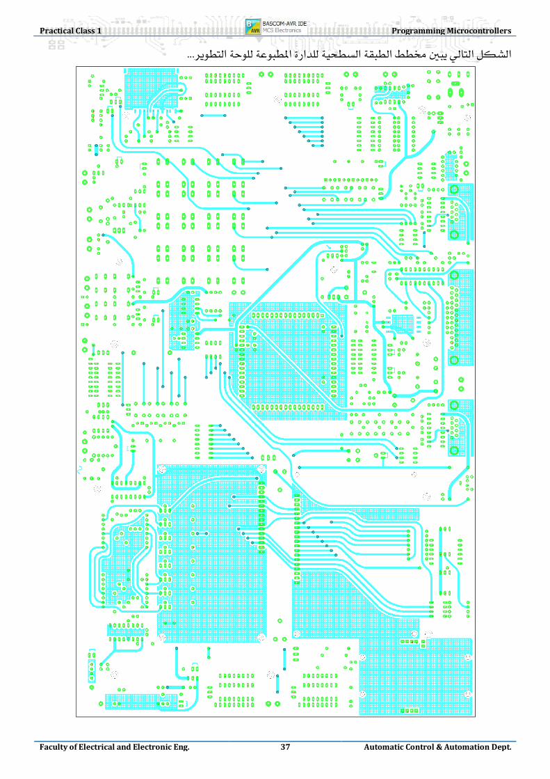
Development Board Schematic & Board Design

24

Practical Class 1 Programming Microcontrollers
Faculty of Electrical and Electronic Eng. 25 Automatic Control & Automation Dept.
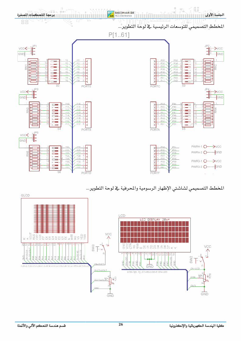
26

Practical Class 1 Programming Microcontrollers
Faculty of Electrical and Electronic Eng. 27 Automatic Control & Automation Dept.
USART
28
I2C EEPROM & RTC
Practical Class 1 Programming Microcontrollers
Faculty of Electrical and Electronic Eng. 29 Automatic Control & Automation Dept.
RS485
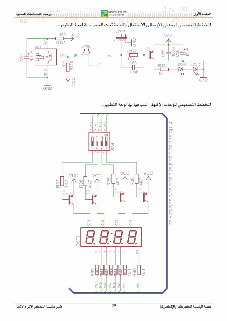
30

Practical Class 1 Programming Microcontrollers
Faculty of Electrical and Electronic Eng. 31 Automatic Control & Automation Dept.
MMC/SD
PWM
32
PS2
Practical Class 1 Programming Microcontrollers
Faculty of Electrical and Electronic Eng. 33 Automatic Control & Automation Dept.
1-Wire
34

Practical Class 1 Programming Microcontrollers
Faculty of Electrical and Electronic Eng. 35 Automatic Control & Automation Dept.

36
Practical Class 1 Programming Microcontrollers
Faculty of Electrical and Electronic Eng. 37 Automatic Control & Automation Dept.

38

Practical Class 1 Programming Microcontrollers
Faculty of Electrical and Electronic Eng. 39 Automatic Control & Automation Dept.

40
Px.0 Px.1 Px.2 Px.3 Px.4 Px.5 Px.6 Px.7
Port
E
INT4~7 UART1
AIN OC3A,B,C
T3 ICP3
RS485 Interface PWM>DAC Four Buttons/Leds1
UART1 with Hand-checking and LEDs Indicators
8-bit DAC Interface
External Port Connector for further connecting and can be set to Pull Up/Down Resistor
Port
B SPI
OC1A,B OC0,2 OC1C
Programmer
MMC/SD Card SPI Interface Speaker IR Sender PWM IR Receiver
Hexadecimal Keypad
External Port Connector for further connecting and can be set to Pull Up/Down Resistor
Port
D INT0~3
UART2 TWI
T1~2 ICP1
Four Buttons/Leds2 ICP1 Relay1 T1 Relay2
PS2 SCK UART2
RTC & EEPROM
External Port Connector for further connecting and can be set to Pull Up/Down Resistor
Port
C
Ex.MI-H
DS1820 GLCD Control Bus
LCD
Quad Seven Segment Control Lines
Dual Led-Matrix Display Data Bus
External Port Connector for further connecting and can be set to Pull Up/Down Resistor
Port
A
Ex.MI-L
GLCD Data Bus
UART2 Hand-checking Basic Card
Quad Seven Segment Data Bus
External Port Connector for further connecting and can be set to Pull Up/Down Resistor
Port
F ADC0~7 JTAG
LDR Resistor
NTC Resistor
Pressure sensor
Variable Resistor
Variable Resistor
4 Switches On a line
Temperature Sensor
JTAG Interface
Port
G
TOSC WR/RD
Dual Led-Matrix Display Control Lines
RC Circuit 23KHZ Crystal x x x
ASK TR ASK RE PS2 Data x x x x x
1 Buttons for Interrupt 4~7 can be set to VCC or GND by Jumper, connected with led indicators. 2 Buttons for Interrupt 0~3 can be set to VCC or GND by Jumper, connected with led indicators.
Related Documents