MANUFACTURING AND DESIGN OF INSULATION SYSTEM FOR AIR COOLED TURBO GENERATOR BY V.P.I PROCESS A PROJECT REPORT SUBMITTED IN PARTIAL FULFILLMENT OF THE REQUIREMENTS FOR THE AWARD OF BACHELOR DEGREE IN ELECTRICAL ENGINEERING SUBMITTED BY G.VENKATESH BABU (04A21A0258) M.K.CHAITANYA SARMA (04A21A0216) M.V.SATYA TEJA (04A21A0254) L.PRANEETH CHAITANYA (03A21A0226) UNDER THE ESTEEMED GUIDANCE OF REGD.OFFICE: BHEL, SIRIFORT, NEWDELHI-110 049 R.K.MANOHAR Sr DGM Quality Control(E.M) BHEL, Ramachandra puram T.Ravi. M.E.., Asst prof. Swarnandhra College Narsapuram

Welcome message from author
This document is posted to help you gain knowledge. Please leave a comment to let me know what you think about it! Share it to your friends and learn new things together.
Transcript
MANUFACTURING AND DESIGN OF INSULATION SYSTEM FOR
AIR COOLED TURBO GENERATOR BY V.P.I PROCESS
A PROJECT REPORT SUBMITTED IN PARTIAL FULFILLMENT OF THE REQUIREMENTS
FOR THE AWARD OF
BACHELOR DEGREE IN
ELECTRICAL ENGINEERING
SUBMITTED BY
G.VENKATESH BABU(04A21A0258)
M.K.CHAITANYA SARMA(04A21A0216)
M.V.SATYA TEJA(04A21A0254)
L.PRANEETH CHAITANYA(03A21A0226)
UNDER THE ESTEEMED GUIDANCE OF
REGD.OFFICE: BHEL, SIRIFORT, NEWDELHI-110 049
R.K.MANOHARSr DGM
Quality Control(E.M)BHEL, Ramachandra puram
T.Ravi. M.E..,Asst prof.
Swarnandhra CollegeNarsapuram

2
CERTIFICATE
This is to certify that the project entitled “MANUFACTURING AND DESIGN OF INSULATION SYSTEM FOR AIR COOLED TURBO GENERATOR BY V.P.I PROCESS”
Submitted byG.VENKATESH BABU (04A21A0258)M.KRISHNA CHAITANYA SARMA (04A21A0216) M.V.SATYA TEJA (04A21A0254) L.PRANEETH CHAITANYA (03A21A0226)
In partial fulfilment of “BACHELORS DEGREE IN ELECTRICAL AND ELECTRONICS ENGINEERING” for the academic Year 2007-2008 of IV-Year from SWARNANDHRA COLLEGE OF ENGINEERING AND TECHNOLOGY, affiliated to JNT UNIVERSITY, WEST GODAVARI DIST., A.P, INDIA.A record of bonafide work carried by them under my guidance in “BHEL, RAMACHANDRAPURAM, HYDERABAD-32”.
SIGNATURE OF PROJECT GUIDE SHRI R.K.MANOHAR
DGM,B.Tech(Elect),(SQC&OR) Electrical Machines,(Quality Control), BHEL,Ramachandrapuram.
3
ABSTRACT
In developing countries like India, power generation is a major break through to meet
the present demands of the nation. Power generation of several types are on forefront, the
dominant component of power generation is TURBO-GENERATOR which produces large capacity,
the word “TURBO” stands for turbine drive. Generally the turbines used to drive these turbo-
generators are of reaction type.
In large-scale industries manufacturing generators, insulation design plays a vital role.
Insulation is known to be the heart of the generator. If insulation fails, generator fails which leads to
the loss of crores of rupees. The latest technology for insulation in the world and adopted by BHEL,
(Hyderabad) unit is “VACUUM PRESSURE IMPREGNATION “which is of resin poor thermosetting
type. This type is preferred as it is highly reliable and possesses good mechanical, thermal properties
and di-electric strength. As the quantity of resin used is less, hence the over all cost of insulation is
reduced.
In our project we have made a detailed study of the VPI system of insulation. This
system is employed by BHEL first in the country and second in the world next to Germany.
Project Associates:
G.Venkatesh Babu (04A21A0258)
M.K.Chaitanya Sarma (04A21A0216)
M.V.Satya Teja (04A21A0254)
L.Praneeth Chaitanya (03A21A0226)
Project Guide External: Project Guide Internal:
R.K.Manohar., Sr.D.G.M, T.Ravi. M.E..,
Quality Control (E.M), Asst prof.
B.H.E.L. R.C.Puram. Swarnandhra College
4
APPROVED BY HOD OF EEE
TABLE OF CONTENTS
1. ABSTRACT 3
1.1 ACKNOWLEDGEMENTS 9
1.2. PROFILE OF BHEL 10
1.3. PREFACE 12
2. INTRODUCTION 13
2.1DRAWBACKS OF EARLY VPI PROCESS 13
2.2 ADVANTAGE OF PRESENT RESIN POOR VPI PROCESS 14
3. INTRODUCTION TO VARIOUS PARTS OF A GENERATOR 16
3.1 STATOR 16
3.2 ROTOR 17
3.3 FIELD CONNECTIONS AND MULTI CONTACTS 19
3.4 EXCITATON SYSTEM 20
3.5 PERMANENT MAGNET GENERATOR AND AVR 21
3.6 VARIOUS LOSSES IN A GENERATOR 23
4. MANUFACTURE OF GENERATOR
4.1VARIOUS STAGES IN MANUFACTURE OF GENERATOR 25
4.1.1 STATOR MANUFACTURING PROCESS 26
4.1.2 STATOR CORE CONSTRUCTION 26
4.1.3 PREPARATION OF STATOR LAMINATIONS 26
4.1.4 RECEPTION OF SILICON STEEL ROLLS 26
4.1.5 SHEARING 26
4.1.6 BLANKING AND NOTCHING 26
4.1.7 COMPOUND NOTCHING 26
4.1.8 INDIVIDUAL NOTCHING 27
5
4.1.9 DEBURRING 27
4.1.10 VARNISHING 27
5 STATOR CORE ASSEMBLY 28
5.1 TRAIL PACKET ASSEMBLY 28
5.2 NORMAL CORE ASSEMBLY 28
5.2.1 STEPPED PACKET ASSEMBLY 28
5.2.2 NORMAL PACKET ASSEMBLY 28
5.2.3 IN PROCESS PRESSING 29
5.2.4 FITTING OF CLAMPING BOLTS 29
6. STATOR WINDING 29
6.1 CONDUCTOR MATERIAL USED IN COIL MANUFACTURING 29
6.2 TYPES OF CONDUCTOR COILS 29
7. ELECTRICAL INSULATION 31
7.1 STATOR WINDING INSULATION SYSTEM FEATURES 34
7.1.1 STRAND INSULATION 34
7.1.2 TURN INSULATION 38
7.1.3 GROUND WALL INSULATION 39
7.1.4 SLOT DISCHARGES 40
7.2 INSULATING MATERIALS 40
7.2.1 CLASSIFICATION OF INSULATING MATERIALS 41
7.2.2 INSULATING MATERIALS FOR ELECTRICAL MACHINES 42
7.3 ELECTRICAL PROPERTIES OF INSULATION AND FEW DEFINITIONS 43
7.3.1 INSULATION RESISTANCE
7.3.2 DIELECTRIC STRENGTH
7.3.3 POWER FACTOR
7.3.4 DIELECTRIC CONSTANT
7.3.5 DIELECTRIC LOSS
8 RESIN IMPREGNATION 44
8.1 INSULATION MATERIALS FOR LAMINATIONS 45
8.2 VARNISH 46
8.3 MATERIAL FOR RESIN POOR BARS 46
8.4 RESIN RICH SYSTEM
MATERIALS FOR RESIN POOR HALF BARS
6
9. MANUFACTURE OF STATOR COILS 48
9.1 FOR RESIN POOR PROCESS 48
9.1.1 RECEPTION OF COPPER CONDUCTORS
9.1.2 TRANSPOSITION
9.1.3 PUTTY OPERATION 49
9.1.4 STACK CONSOLIDATION
9.1.5 BENDING
9.1.6 FINAL TAPING
9.2 FOR RESIN RICH PROCESS 50
9.2.1 PUTTY WORK
9.2.2 FINAL TAPING
9.2.3 FINAL BAKING 51
10. AN OVERVIEW
10.1 ADVANTAGES OF RESIN POOR SYSTEM 52
10.2 DISADVANTAGES OF RESIN POOR SYSTEM 52
10.3 ADVANTAGES OF RESIN RICH SYSTEM
10.4 DISADVANTAGES OF RESIN RICH SYSTEM
11. ASSEMBLY OF STATOR 52
11.1 RECEPTION OF STATOR CORE 53
11.2 WINDING HOLDERS ASSEMBLY
11.3 STIFFENER ASSEMBLY
11.4 EYE FORMATION
11.5 CONNECTING RINGS ASSEMBLY
11.6 PHASE CONNECTORS
12. THE VPI PROCESS
12.1 INTRODUCTION TO VPI PROCESS 54
12.2 HISTORY 54
12.3 VPI PROCESS FOR RESIN POOR INSULATED JOBS 57
12.3.1 GENERAL 57
12.3.2 PREHEATING
12.3.3 VACUUM CYCLE
12.3.4 IMPREGNATION
12.3.5 POST CURING
7
12.3 .6 ELECTRICAL TESTING 61
12.4 GLOBAL PROCESSING 61
12.5 RESIN MANAGEMENT 61
12.6 SPECIFIC INSTRUCTIONS 62
12.7 PRECAUTIONS
12.8 FEATURES AND BENEFITS
13. FACILITIES AVAILABLE IN VPI PLANT BHEL 63
13.1 DATA COLLECTION OF SAMPLES 65
13.1.1INDO-BHARAT –II ROTOR 65
13.1.2 INDO BHARAT –II STATOR 68
13.1.3 High voltage levels of stator/rotor windings for multi turn machines 71
13.1.4 Testing results of indo bharat-ii rotor 72
13.1.5 Testing results of indo bharat-ii stator 73
14. Comparision between resin poor and resin rich systems 74
14.1 Drawbacks 74
14.2 Suggestions
14.3 justification 75
15. Present insulation systems used in the world 75
15.1 Westinghouse electric co: Thermalastic™ 76
15.2 General electric co:
Micapals i and ii™, epoxy mica mat™, micapal ht™ and hydromat™ 77
15.3 Alsthom, gec alsthom, alstom power:
Isotenax™, resitherm™, resiflex™, resivac™ and duritenax™ 77
15.4 Siemens ag, kwu: micalastic 78
15.5 Abb industrie ag:
micadur™, micadur compact™, micapact™ and micarex™ 79
15.6 Toshiba corporation: tosrich™ and tostight-i™ 79
15.7 Mistubishi electric corporation 80
15.8 Hitachi ltd: hi-resin™ and super high-resin 80
15.9 Summary of present day insulation 80
16. a new trend in insulation system
16.1 Micalastic 81
16.2 Micalastic insulation in itaipu’ 82
8
17. Conclusion 83
18. BIBLIOGRAPHY
LIST OF TABLES
Classification of insulations according to temperature
Insulating materials for electrical machines
Properties of an electrical insulation
Materials used in resin rich and resin poor process
Table showing temperature and time to be maintained for different type of jobs in VPI
LIST OF FIGURES
Photograph of a small round rotor
Figure showing the flow of eddy currents in rotor body with and without laminations
Flow diagram showing various stages in generator manufacture
Fig showing the shape of laminations after completion of notching and deburring operation
Roebel and diamond pulled coils
Schematic diagram for a 3-Ф Y connected stator winding with 2 parallel conductors per phase
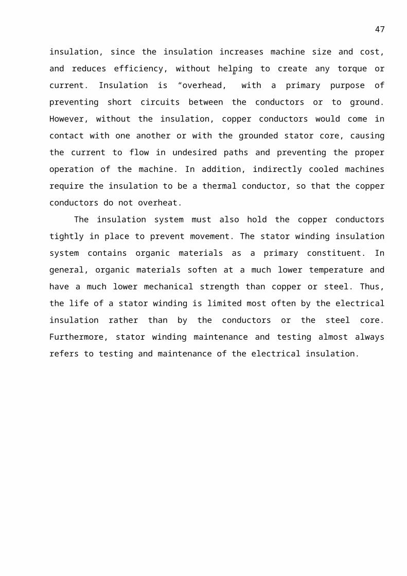
Photographs of end windings and slots of random wound stator
Photograph of a form wound stator winding
A single form wound coil being inserted into two slots
C.S of a random stator winding slot
C.S of a form wound multi-turn slots containing
a.) form wound multi-turn coils.
b.) directly cooled roebel bars
C.S of multi-turn coil, where the turn insulation and strand insulation are same
Side view showing one way of transposing insulated strands in stator bar
C.S of multi-turn coil with 3 turns and 3 strands per turn
Layout of mould used in baking of stator by resin rich process
Vertical VPI tank for smaller jobs
Resin tank in which resin is stored
9
LIST OF SYMBOLS ABBREVATIONS AND NOMENCLATURE
C.S. Cross Section
AVR Automatic Voltage Regulator
PMG Permanent Magnetic Generator
VPI Vacuum Pressurised Impregnation

10
1.1. ACKNOWLEDGEMENTS
11
1.2.PROFILE OF B.H.E.L.
Bharat Heavy Electrical Limited (BHEL) is today the largest engineering enterprise of India with
an excellent track record of performance. Its first plant was set up at Bhopal in 1956 under technical
collaboration with M/s. AEI, UK followed by three more major plants at Haridwar, Hyderabad and
Tiruchirapalli with Russian and Czechoslovak assistance.
These plants have been at the core of BHEL’s efforts to grow and diversify and become
India’s leading engineering company. The company now has 14 manufacturing divisions, 8 service
centres and 4 power sector regional centres, besides project sites spread all over India and abroad
and also regional operations divisions in various state capitals in India for providing quick service to
customers.
BHEL manufactures over 180 products and meets the needs of core-sectors like power,
industry, transmission, transportation (including railways), defence, telecommunications, oil
business, etc. Products of BHEL make have established an enviable reputation for high quality and
reliability.
BHEL has installed equipment for over 62,000 MW of power generation-for Utilities, Captive
and Industrial users. Supplied 2,00,000 MVA transformer capacity and sustained equipment
operating in Transmission & Distribution network up to 400kV – AC & DC, Supplied over 25,000
Motors with Drive Control System Power projects. Petrochemicals, Refineries, Steel, Aluminium,
Fertiliser, Cement plants etc., supplied Traction electric and AC/DC Locos to power over 12,000 Km
Railway network.
Supplied over one million Valves to Power Plants and other Industries. This is due to the
emphasis placed all along on designing, engineering and manufacturing to international standards
by acquiring and assimilating some of the best technologies in the world from leading companies in
USA, Europe and Japan, together with technologies from its-own R & D centres BHEL has acquired
12
ISO 9000 certification for its operations and has also adopted the concepts of Total Quality
Management (TQM).
BHEL presently has manufactured Turbo-Generators of ratings up to 560 MW and is in the
process of going up to 660 MW. It has also the capability to take up the manufacture of ratings unto
1000 MW suitable for thermal power generation, gas based and combined cycle power generation
as-well-as for diverse industrial applications like Paper, Sugar, Cement, Petrochemical, Fertilisers,
Rayon Industries, etc. Based on proven designs and know-how backed by over three decades of
experience and accreditation of ISO 9001. The Turbo-generator is a product of high-class
workmanship and quality. Adherence to stringent quality-checks at each stage has helped BHEL to
secure prestigious global orders in the recent past from Malaysia, Malta, Cyprus, Oman, Iraq,
Bangladesh, Sri Lanka and Saudi Arabia. The successful completion of the various export projects in
a record time is a testimony of BHEL’s performance.
Established in the late 50’s, Bharat Heavy Electrical Limited (BHEL) is, today, a name to
reckon with in the industrial world. It is the largest engineering and manufacturing enterprises of its
kind in India and is one of the leading international companies in the power field. BHEL offers over
180 products and provides systems and services to meet the needs of core sections like: power,
transmission, industry, transportation, oil & gas, non-conventional energy sources and
telecommunication. A wide-spread network of 14 manufacturing divisions, 8 service centres and 4
regional offices besides a large number of project sites spread all over India and abroad, enables
BHEL to be close to its customers and cater to their specialised needs with total solutions-efficiently
and economically. An ISO 9000 certification has given the company international recognition for its
commitment towards quality. With an export presence in more than 50 countries BHEL is truely
India’s industrial ambassador to the world.

13
1. 3. Preface
Power is the basic necessity for economic development of a country. The production
of electrical energy and its per capital consumption is deemed as an index of standard of living in a
nation in the present day civilization. Development of heavy or large-scale industries, as well as
medium scale industries, agriculture, transportation etc, totally depend on electrical power
resources of engineers and scientists to find out ways and means to supply required power at
cheapest rate. The per capital consumption on average in the world is around 1200KWH, the figure
is very low for our country and we have to still go ahead in power generation to provide a decent
standard of living for people.
An AC generator is a device, which converts mechanical energy to electrical energy.
The alternator as it is commonly called works on the principle of ‘Electro Magnetic Induction’. Turbo
generators are machines which can generate high voltages and capable of delivering KA of
currents .so the designer should be cautious in designing the winding insulation. So insulation design
plays a major role on the life of the Turbo Generator. In our project we deal with the “Manufacture
process of turbo generator and its insulation design by VPI process.”
The first half of project is concerned with the aspects of generator manufacturing
comprising of stator manufacturing, in a step by step procedure involving different stages, and the
latter stage includes the insulation design of the generator by VPI process in a detailed manner,
which completes the generator design.
We more over stress mainly on VPI insulation process. Before going deep into the
topic, we will start with a brief introduction.

14
2. Introduction
Electrical insulating materials are defined as materials that offer a large resistance to
the flow of current and for that reason they are used to keep the current in its proper path i.e. along
the conductor. Insulation is the heart of the generator. Since generator principle is based on the
induction of e.m.f in a conductor when placed in a varying magnetic field. There should be proper
insulation between the magnetic field and the conductors. For smaller capacities of few KW, the
insulation may not affect more on the performance of the generator but for larger capacities of few
MW (>100MW) the optimisation of insulation is an inevitable task, moreover the thickness of
insulation should be on par with the level of the voltage, also non homogenic insulation provisions
may lead to deterioration where it is thin and prone to hazardous short circuits, also the insulating
materials applied to the conductors are required to be flexible and have high specific (dielectric)
strength and ability to withstand unlimited cycles of heating and cooling.
Keeping this in view among other insulating materials like solids gases etc liquid
dielectrics are playing a major role in heavy electrical equipment where they can embedded deep
into the micro pores and provide better insulating properties. Where as solid di-electrics provide
better insulation with lower thickness and with greater mechanical strength. So the process of
insulation design which has the added advantage of both solid and liquid dielectrics would be a
superior process of insulation design. One such process which has all the above qualities is the VPI
(vacuum pressurised impregnation) process and has proven to be the best process till date.
2.1 Drawbacks of Early VPI Process:
DR. MEYER brought the VPI system with the collaboration of WESTING HOUSE in the year
1956. It has been used for many years as a basic process for thorough filling of all interstices in
insulated components, especially high voltage stator coils and bars. Prior to development of
thermosetting resins, the widely used insulation system for 6.6kv and higher voltages was a VPI
system in which, Bitumen Bonded Mica Flake Tape is used as main ground insulation. The bitumen
is heated up to about 180C to obtain low viscosity which aids thorough impregnation.
To assist penetration, the pressure in the autoclave was raised to 5 or 6 atmospheres. After
appropriate curing and calibration, the coils or bars were wound and connected up in the normal
manner. These systems performed satisfactorily in service provided they were used in their thermal
limitations.
15
In the late 1930’s and early 1940’s, however, many large units, principally turbine
generators, failed due to inherently weak thermoplastic nature of bitumen compound.
Failures were due to two types of problems:
a. Tape separation
b. Excessive relaxation of the main ground insulation.
Much development work was carried out to try to produce new insulation systems, which
didn’t exhibit these weaknesses.
The first major new system to overcome these difficulties was basically a fundamental
improvement to the classic Vacuum Pressure Impregnation process: Coils and bars were insulated
with dry mica flake tapes, lightly bonded with synthetic resin and backed by a thin layer of fibrous
material. After taping, the bars or coils were vacuum dried and pressure impregnated in polyester
resin. Subsequently, the resin was converted by chemical action from a liquid to a solid compound
by curing at an appropriate temperature, e.g. 150C. this so called thermosetting process enable
coils and bars to be made which didn’t relax subsequently when operating at full service
temperature. By building in some permanently flexible tapings at the evolutes of diamond shaped
coils, it was practicable to wind them without difficulty. Thereafter, normal slot packing, wedging,
connecting up and bracing procedures were carried out. Many manufacturers for producing their
large coils and bars have used various versions of this Vacuum Pressure Impregnation procedure for
almost 30 years.
The main differences between systems have been used is in the type of micaceous tapes
used for main ground insulation and the composition of the impregnated resins. Although the first
system available was styrenated polyester, many developments have taken place during the last
two decades. Today, there are several different types of epoxy, epoxy-polyester and polyester resin
in common use. Choice of resin system and associated micaceous tape is a complex problem for the
machine manufacturer.
Although the classic Vacuum Pressure Impregnation technique has improved to a significant
extent, it is a modification to the basic process, which has brought about the greatest change in the
design and manufacture of medium-sized a.c. industrial machines. This is the global impregnation
process. Using this system, significant increases in reliability, reduction in manufacturing costs and
improved output can be achieved.
16
2.2 Advantage of present resin poor VPI process:
VPI is a process, which is a step above the conventional vacuum system. VPI includes
pressure in addition to vacuum, thus assuring good penetration of the varnish in the coil. The result
is improved mechanical strength and electrical properties. With the improved penetration, a void
free coil is achieved as well as giving greater mechanical strength. With the superior varnish
distribution, the temperature gradient is also reduced and therefore, there is a lower hot spot rise
compared to the average rise.
In order to minimise the overall cost of the machine & to reduce the time cycle of the
insulation system vacuum pressure Impregnated System is used. The stator coils are taped with
porous resin poor mica tapes before inserting in the slots of cage stator, subsequently wounded
stator is subjected to VPI process, in which first the stator is vacuum dried and then impregnated in
resin bath under pressure of Nitrogen gas.
17
3 Introduction to various parts of a Generator:
The manufacturing of a generator involves in manufacturing of all the parts of the
generator separately as per the design requirements and assembling them for the operation. It is
worth knowing the parts of the Turbo Generator. Usually for larger generators the assembling is
done at the generator installation area in order to avoid the damage due to mechanical stresses
during transportation, also this facilitates easy transportation. Let us have a view about various
parts of a turbo generator. Parts of a turbo generator:
1. Stator
2. Rotor
3. Excitation system
4. Cooling system
5. Insulation system
6. Bearings
3.1 STATOR: 3.1.1 STATOR FRAME
The stator frame is of welded steel single piece construction. It supports the laminated core
and winding. It has radial and axial ribs having adequate strength and rigidity to minimise core
vibrations and suitably designed to ensure efficient cooling. Guide bards are welded or bolted inside
the stator frame over which the core is assembled. Footings are provided to support the stator
foundation.
3.1.2 STATOR CORE
The stator core is made of silicon steel sheets with high permeability and low hysteresis and
eddy current losses. The sheets are suspended in the stator frame from insulated guide bars.
Stator laminations are coated with synthetic varnish; are stacked and held between sturdy
steel clamping plates with non-magnetic pressing fingers, which are fastened or welded to the
stator frame.
In order to minimise eddy current losses of rotating magnetic flux which interacts with the
core, the entire core is built of thin laminations. Each lamination layer is made of individual
segments.
The segments are punched in one operation from electrical sheet steel lamination having high
silicon content and are carefully deburred. The stator laminations are assembled as separate cage
core without the stator frame. The segments are staggered from layer to layer so that a core of high

18
mechanical strength and uniform permeability to magnetic flux is obtained. On the outer
circumference the segments are stacked on insulated rectangular bars, which hold them in position.
To obtain optimum compression and eliminate looseness during operation the laminations are
hydraulically compressed and heated during the stacking procedure. To remove the heat, spaced
segments are placed at intervals along the core length, which divide the core into sections to
provide wide radial passages for cooling air to flow.
The purpose of stator core is
1. To support the stator winding.
2. To carry the electromagnetic flux generated by rotor winding.
So selection of material for building up of core plays a vital role.
3.1.3 STATOR WINDING: The stator winding is a fractional pitch two layer type, it consisting of individual bars.
The bars are located in slots of rectangular cross section which are uniformly distributed on the
circumference of the stator core.
In order to minimize losses, the bars are compared of separately insulated strands which
are exposed to 360.degrees transposing
To minimize the stator losses in the winding, the strands of the top and bottom bars are
separately brazed and insulated from each other.
3.2 ROTOR:
3.2.1 ROTOR SHAFT:
Rotor shaft is a single piece solid forging manufactured from a vacuum casting. Slots
for insertion of field winding are milled into the rotor body. The longitudinal slots are distributed
over the circumference. So that solids poles are obtained. To ensure that only high quality forgings
are used, strengthen test, material analysis and ultrasonic tests are performed during manufacture
of the rotor. After completion, the rotor is based in various planes at different speeds and then
subjected to an over speed test at 120% of rated speed for two minutes.
3.2.2. ROTOR WINDING AND RETAINING RINGS:
The rotor winding consisting of several coils, which are inserted into the slots and
series connected such that two coils groups from one pole. Each coil consists of several connected
turns, each of which consists of two half turns which are connected by brazing in the end section.

19
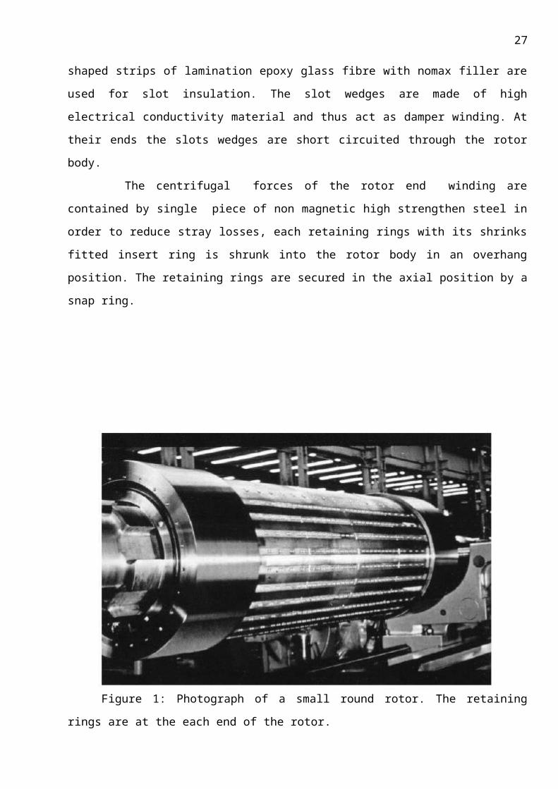
The individual turns of the coils are insulated against each other, the layer insulation L-shaped strips
of lamination epoxy glass fibre with nomax filler are used for slot insulation. The slot wedges are
made of high electrical conductivity material and thus act as damper winding. At their ends the slots
wedges are short circuited through the rotor body.
The centrifugal forces of the rotor end winding are contained by single piece of non
magnetic high strengthen steel in order to reduce stray losses, each retaining rings with its shrinks
fitted insert ring is shrunk into the rotor body in an overhang position. The retaining rings are
secured in the axial position by a snap ring.
Figure 1: Photograph of a small round rotor. The retaining rings are at the each end of the
rotor.
3.3 FIELD CONNECTION AND MULTICONTACTS:
The field current is supplied to the rotor through multi contact system arranged at the
exciter side shaft end.
3.3.1 BEARINGS:
20
The generator rotor is supported in two sleeve bearings. To eliminate shaft current the
exciter and bearing is insulated from foundation plate and oil piping.
The temperature of each bearing is maintained with two RTD’s (Resistance Temperature
Detector) embedded in the lower bearing sleeve so that the ensuring point is located directly below
the Babbitt. All bearings have provisions for fitting vibration pick up to monitor shaft vibrations.
The oil supply of bearings is obtained from the turbine oil system.
3.4 EXCITATION SYSTEM:In all industrial applications, the electrical power demand is ever increasing. This
automatically demands for the design, development and construction of increasingly large capacity
Synchronous generators. These generators should be highly reliable in operation to meet the
demand. This calls for a reliable and sophisticated mode of excitation system.
When the first a.c generators were introducing a natural choice for the supply of field
systems was the DC exciter. DC exciter has the capability for equal voltage output of either polarity,
which helps in improving the generator transient performance. DC exciters, how ever, could not be
adopted for large ratings because of the problems in the design commutator and brush gear, which
is economically unattractive. Of –course, the problems are not uncommon in power stations but Of
the environment with sulphur vapours, acidic fumes as in the cases of petrochemical and fertilizer
industries, exposure of DC exciter. This adds to the problem of design.
Types of a.c exciters are:
(1) High frequency excitation
(2) Brush less excitation
(3) Static excitation
The high frequency D.C exciter is a specially designed “inductor type alternator” with no
winding on its rotor. It is designed to operate at high frequency to reduce the size of the rotor; the
a.c exciter was very reliable in operation. Though this system eliminates all problems associated
with commutator, it is not free from problems attributable to slip rings and its brush gear. Thus
brushless excitation system was introduced.
The BL exciter consists of field winding on the stator. This system proved to be highly reliable
and required less maintenance. Absence of power cables and external ac power supplies males the
21
system extremely reliable. The problem associated with brushes like fast wear out of brush,
sparkling etc, are eliminated.
This suffers from the disadvantage of lack of facility for field suppression in the case of an
internal fault in generator.
The system comprises shaft driven AC exciter with rotating diodes.
3.5 PERMANENT MAGNET GENERATOR AND AVR:
This system is highly reliable with least maintenance and is ideally suitable for gas driven
generators.
The static excitation system was developed contemporarily as an alternative to brush less
excitation system. This system was successfully adapted to medium and large capacity Turbo
generators. Though the system offers very good transient performance, the problems associated
with slip rings and brush gear system are still present.
This system consists of rectifier transformer, thyristor converts, field breaker and AVR. This
system is ideally suitable where fast response is called for. The system is flexible in operation and
needs very little maintenance.
Thus, each excitation system has its own advantages and disadvantages. The selection of
system is influenced by the transient response required, nature of pollution and pollution level in
the power plant and cost of equipment.
Exciters are those components, which are used for giving high voltage to the generator
during the start up conditions. The main parts that are included in the exciter assembly are:
(1) Rectifier wheels
(2) Three phase main exciter
(3) Three phase pilot exciter
(4) Metering and supervisory equipment
3.5.1 RECTIFIER WHEELS:
The main components of the rectifier wheels are Silicon Diodes, which are arranged in the
rectifier wheels in a three-phase bridge circuit. The internal arrangement of diode is such that the
contact pressure is increased by centrifugal force during rotation.
There are some additional components contained in the rectified wheels. One diode each is
mounted in each light metal heat sink and then connected in parallel. For the suppression of
22
momentary voltage peaks arising from commutation, RC blocks are provided in each bridge in
parallel with one set of diodes. The rings from the positive shrunk on to the shaft. This makes the
circuit connections minimum and ensures accessibility of all the elements.
3.5.2 THREE PHASE PILOT EXCITER:
The three phase pilot exciter is a six-pole revolving field unit; the frame accommodates the
laminated core with the three-phase winding. The rotor consists of a hub with poles mounted on it.
Each pole consists of separate permanent magnets, which are housed, in non-metallic enclosures.
The magnets are placed between the hub and the external pole shoe with bolts. The rotor hub is
shrunk on to the free shaft end.
3.5.3.THREE PHASE MAIN EXCITER:
Three phases main exciter is a six-pole armature unit; the poles are arranged in the frame
with the field and damper winding. The field winding is arranged on laminated magnetic poles. At
the pole shoe, bars are provided which are connected to form a damper winding.
The rotor consists of stacked laminations, which are compressed through bolts over
compression rings. The three- phase winding is inserted in the slots of the laminated rotor. The
winding conductors are transposed with in the core length and end turns of the rotor windings are
secure with the steel bands. The connections are made on the side facing of the rectifier wheels.
After full impregnation with the synthetic resin and curing, the complete rotor is shrunk on to the
shaft.
3.5.4 .AUTOMATIC VOLTAGE REGULATOR:
The general automatic voltage regulator is fast working solid thyristor controlled equipment.
It has two channels, one is auto channel and the other is manual. The auto channel is used for the
voltage regulation and manual channel is used for the current regulation. Each channel will have its
own firing for reliable operation.
The main features of AVR are:
(1) It has an automatic circuit to control outputs of auto channel and manual channel
and reduces disturbances at the generator terminals during transfer from auto
regulation to manual regulation.
(2) It is also having limiters for the stator current for the optimum utilization of lagging
and leading reactive capabilities of turbo generator.
(3) There will be automatic transfer from auto regulation to manual regulation in
case do measuring PT fuse failure or some internal faults in the auto channel.

23
(4) The generator voltage in both channels that is in the auto channel and the manual
channel can be controlled automatically.
3.5.5 COOLING SYSTEM:
Cooling is one of the basic requirements of any generator. The effective working of generator
considerably depends on the cooling system. The insulation used and cooling employed is inter-
related.
The losses in the generator dissipates as the heat, it raises the temperature of the generator.
Due to high temperature, the insulation will be affected greatly. So the heat developed should be
cooled to avoid excessive temperature raise. So the class of insulation used depends mainly on
cooling system installed.
There are various methods of cooling, they are:
a. Air cooling- 60MW
b. Hydrogen cooling-100MW
c. Water cooling –500MW
d. H 2 & Water cooling – 1000MW
Hydrogen cooling has the following advantages over Air-cooling:
1. Hydrogen has 7 times more heat dissipating capacity.
2. Higher specific heat
3. Since Hydrogen is 1/14th of air weight. It has higher compressibility
4. It does not support combustion.
DISADVANTAGES:
1. It is an explosive when mixes with oxygen.
2. Cost of running is higher.
Higher capacity generators need better cooling system.
3.6 VARIOUS LOSSES IN A GENERATOR
In generators, as in most electrical devices, certain forces act to decrease the efficiency. These forces, as they affect the generator, are considered as losses and may be defined as follows:
3.6.1 Copper loss in the winding.
3.6.2 Magnetic Losses.
24
3.6.3 Mechanical Losses
3.6.1 Copper loss:
The power lost in the form of heat in the armature winding of a generator is known as Copper loss. Heat is generated any time current flows in a conductor.
I2R loss is the Copper loss, which increases as current increases. The amount of heat generated is also proportional to the resistance of the conductor. The resistance of the conductor varies directly with its length and inversely with its cross- sectional area. Copper loss is minimized in armature windings by using large diameter wire. These includes rotor copper losses and Stator copper losses
3.6.2 Magnetic Losses (also known as iron or core losses)(i) Hysteresis loss (Wh) Hysteresis loss is a heat loss caused by the magnetic properties of the armature. When an armature core is in a magnetic field the magnetic particles of the core tend to line up with the magnetic field. When the armature core is rotating, its magnetic field keeps changing direction. The continuous movement of the magnetic particles, as they try to align themselves with the magnetic field, produces molecular friction. This, in turn, produces heat. This heat is transmitted to the armature windings. The heat causes armature resistances to increase. To compensate for hysteresis losses, heat-treated Silicon steel laminations are used in most dc generator armatures. After the steel has been formed to the proper shape, the laminations are heated and allowed to cool. This annealing process reduces the hysteresis loss to a low value.
(ii) Eddy Current Loss (We):The core of a generator armature is made from soft iron, which is a conducting material with desirable magnetic characteristics. Any conductor will have currents induced in it when it is rotated in a magnetic field. These currents that are induced in the generator armature core are called EDDY CURRENTS. The power dissipated in the form of heat, as a result of the eddy currents, is considered a loss.
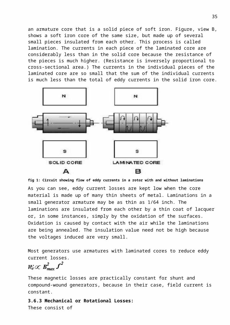
Eddy currents, just like any other electrical currents, are affected by the resistance of the material in which the currents flow. The resistance of any material is inversely proportional to its cross-sectional area. Figure, view A, shows the eddy currents induced in an armature core that is a solid piece of soft iron. Figure, view B, shows a soft iron core of the same size, but made up of several small pieces insulated from each other. This process is called lamination. The currents in each piece of the laminated core are considerably less than in the solid core because the resistance of the pieces is much higher. (Resistance is inversely proportional to cross-sectional area.) The currents in the individual pieces of the laminated core are so small that the sum of the individual currents is much less than the total of eddy currents in the solid iron core.

25
fig 1: Circuit showing flow of eddy currents in a rotor with and without laminations
As you can see, eddy current losses are kept low when the core material is made up of many thin sheets of metal. Laminations in a small generator armature may be as thin as 1/64 inch. The laminations are insulated from each other by a thin coat of lacquer or, in some instances, simply by the oxidation of the surfaces. Oxidation is caused by contact with the air while the laminations are being annealed. The insulation value need not be high because the voltages induced are very small.
Most generators use armatures with laminated cores to reduce eddy current losses.
These magnetic losses are practically constant for shunt and compound-wound generators, because in their case, field current is constant.
3.6.3 Mechanical or Rotational Losses: These consist of (i) friction loss at bearings.(ii) Air-friction or windage loss of rotating rotor armature.These are about 10 to 20% of F.L losses. Careful maintenance can be instrumental in keeping bearing friction to a minimum. Clean bearings and proper lubrication are essential to the reduction of bearing friction. Brush friction is reduced by assuring proper brush seating, using proper brushes, and maintaining proper brush tension.
Usually, magnetic and mechanical losses are collectively known as Stray Losses. These are also known as rotational losses for obvious reasons.
As mentioned above, these losses are responsible for the rise in temperature of the generator body hence an appropriate insulation should be used. Also the insulation should withstand the generator voltage and currents. So an insulation whose breakdown voltage is of 5 to 6 times the normal voltage is taken as Safety factor.
26
4. MANUFACTURE OF GENERATOR
4 . 1 Various stages in generator manufacturing:
In our project we have a detail study of only stator, rotor and the insulation system
used for it. The parts excitation system, cooling system and bearings are external to the generator
and are treated as a completed one and are out of scope of our record. Now, generator
manufacturing can be broadly divided into three main parts:
4.1.1 Stator manufacture.
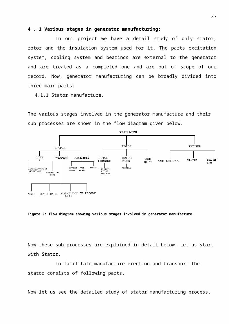
The various stages involved in the generator manufacture and their sub processes are shown in the
flow diagram given below.
27
Figure 2: flow diagram showing various stages involved in generator manufacture.
Now these sub processes are explained in detail below. Let us start with Stator.
To facilitate manufacture erection and transport the stator consists of following parts.
Now let us see the detailed study of stator manufacturing process.
4.1.1 STATOR MANUFACTURE PROCESS:
This stator manufacturing is a combination of two individual sub processes, namely
Stator core construction and
Coil construction and their assembly.
4.1 .2 STATOR CORE CONSTRUCTION:
4.1.3 PREPARATION OF STATOR LAMINATIONS
4.1.4 Reception of silicon steel rolls:
The silicon steel rolls received are checked for their physical, chemical, mechanical and
magnetic properties as per the specifications mentioned above.
SES LAB, 03/26/08,
28
In order to reduce the Hysterisis loss, silicon alloyed steel, which has low Hysterisis
constant is used for the manufacture of core. The composition of silicon steel is
Steel - 95.8 %
Silicon - 4.0 %
Impurities- 0.2 %
From the formula for eddy current loss it is seen that eddy current loss depends on
the thickness of the laminations. Hence to reduce the eddy current loss core is made up of
thin laminations which are insulated from each other. The thickness of the laminations is
about 0.5 mm. The silicon steel sheets used are of COLD ROLLED NON-GRAIN ORIENTED
(CRANGO) type as it provides the distribution of flux throughout the laminated sheet.
4.1.4 Shearing:
The cold rolled non grained oriented (CRNGO) steel sheets are cut to their outer
periphery to the required shapes by feeding the sheet into shearing press. For high rating
machines each lamination is build of 6 sectors (stampings), each of 60 cut according to the
specifications.
4.1.5 Blanking and notching:
Press tools are used in making the core bolt holes and other notches for the laminations.
Press tools are mainly of two types.
i. Compound notching tools.
ii. Individual notching tools.
4.1.6 COMPOUND OPERATION:
In this method the stamping with all the core bolt holes, guiding slots and winding
slots is manufactured in single operation known as Compound operation and the press tool
used is known as Compounding tool. Compounding tools are used for the machines rated
above 40 MW. Nearly 500 tons crank press is used for this purpose.
4.1.7 INDIVIDUAL OPERATIONS:
In case of smaller machines the stampings are manufactured in two operations. In
the first operation the core bolt holes and guiding slots are only made. This operation is
known as Blanking and the tools used are known as Blanking tools. In the second operation
the winding slots are punched using another tool known as Notching tool and the operation
is called Notching.
4.1.8 Deburring operation :
29
In this operation the burrs in the sheet due to punching are deburred. There are
chances of short circuit within the laminations if the burrs are not removed. The permissible
is about 5 micrometer. For deburring punched sheets are passed under rollers to remove
the sharp burs of edges.
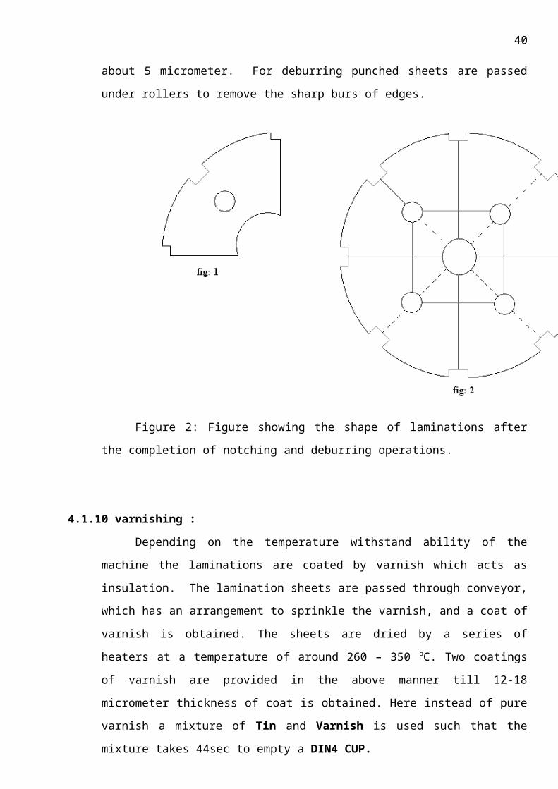
Figure 2: Figure showing the shape of laminations after the completion of notching
and deburring operations.
4.1.10 varnishing :
Depending on the temperature withstand ability of the machine the laminations are
coated by varnish which acts as insulation. The lamination sheets are passed through
conveyor, which has an arrangement to sprinkle the varnish, and a coat of varnish is
obtained. The sheets are dried by a series of heaters at a temperature of around 260 – 350 oC. Two coatings of varnish are provided in the above manner till 12-18 micrometer thickness
of coat is obtained. Here instead of pure varnish a mixture of Tin and Varnish is used such
that the mixture takes 44sec to empty a DIN4 CUP.
The prepared laminations are subjected to following tests.

30
i) Xylol test - To measure the chemical resistance.
ii) Mandrel test - When wound around mandrel there should not be any cracks.
iii) Hardness test - Minimum 7H pencil hardness.
iv) IR value test - For 20 layers of laminations insulation resistance should not be less than
1M.
5 STATOR CORE ASSEMBLY:
5.1 TRAIL PACKET ASSEMBLY:
Clamping plate is placed over the assembly pit; stumbling blocks are placed between the
clamping plates and the assembly pit. Clamping plate is made parallel to the ground by checking
with the spirit level. One packet comprising of 0.5 mm thickness silicon steel laminations is
assembled over the clamping plates by using mandrels and assembly pit .after assembling one
packet thickness of silicon laminations, inner diameter of the core is checked as per the drawing also
the slot freeness is checked with inspection drift .There should not be any projections inside or
outside the slot. If all the conditions are satisfied the normal core assembly is carried out by
dismantling the trial packets.
5.2 NORMAL CORE ASSEMBLY
5.2.1 Stepped packed assembly:
Steeped packets are assembled from the clamping plate isolating each packet with ventilation
laminations up to 4 to 5 packets of thickness 10cms for an air cooled turbo generator of 120MW.
5.2. 2 Normal packet assembly: Normal packet assembly is carried out using 0.5 mm silicon steel laminations up to
required thickness of 30mm by using mandrills and inspection drift after normal packet assembly
completion 1 layer of HGL laminations are placed and one layer of ventilation lamination are placed
and again normal packet assembly is carried as above. The thickness of each lamination is 0.5 mm
and the thickness of lamination separating the packets is about 1 mm. The lamination separating
each packet has strips of nonmagnetic material that are welded to provide radial ducts. The
segments are staggered from layer to layer so that a core of high mechanical strength and uniform
permeability to magnetic flux is obtained. Stacking mandrels and bolts are inserted into the
windings slot bores during stacking provide smooth slot walls.

31
5.2.3 In process pressings
To obtain the maximum compression and eliminate under setting during operation, the
laminations are hydraulically compressed and heated during the stacking procedure when certain
heights of stacks are reached.
The packets are assembled as above up to 800mm as above and 1st pressing is carried
using hydraulic jacks up to 150kg/cm2 and the pressing is carried out for every 800mm and a pre
final pressing is done before the core length almost reach the actual core. Now the core is tested for
the design specifications and the compensation is done by adding or removing the packets.
5.2.4 Fitting of clamping bolts:
The complete stack is kept under pressure and locked in the frame by means of clamping
bolts and pressure plates. The clamping bolts running through the core are made of nonmagnetic
steel and are insulated from the core and the pressure plates to prevent them from short circuiting
the laminations and allowing the flow of eddy currents.
The pressure is transmitted from the clamping plates to the core by clamping fingers. The
clamping fingers extend up to the ends of the teeth thus, ensuring a firm compression in the area of
the teeth. The stepped arrangement of the laminations at the core ends provides an efficient
support to tooth portion and in addition contributes to the reduction of stray load losses and local
heating in that area due to end leakage flux.
The clamping fingers are also made of non-magnetic steel to avoid eddy-current losses. After
compression and clamping of core the rectangular core key bars are inserted into the slots provided
in the back of the core and welded to the pressure plates. All key bars, except one, are insulated
from the core to provide the grounding of the core.
6 WINDING:The next important consideration is winding. The stator winding and rotor winding consist of several
components, each with their own function. Furthermore, different types of machines have different
components. Stator windings are discussed separately below.
6.1 Stator WindingThere are three main components in a stator, they are
6.2 copper conductors (although aluminum is sometimes used)
6.3 The stator core
32
6.4 Insulation.
6.1 Conducting material used in coil manufacturing:
Copper material is used to make the coils. This is because
i) Copper has high electrical conductivity with excellent mechanical properties
ii) Immunity from oxidation and corrosion
iii) It is highly malleable and ductile metal.
6.2 TYPES OF CONDUCTOR COILS:
Basically there are three types of stator winding structures employed over the range from 1 KW to
1000 MW.
1. Random wound stators.
2. Form-wound stators using multi turn coils.
3. Form-wound stators using Roebel bars.
Out of these, two types of coils are manufactured and used in BHEL, Hyderabad.
1) Diamond pulled multi-turn coil (full coiled).
2) Roebel bar (half-coil).
Add here diag of roebel and diamond pulled coilsIn general, random-wound stators are typically used for machines less than several hundred
KW. Form-wound coil windings are used in most large motors and many generators rated up to 50
to 100 MVA. Roebel bar windings are used for large generators. Although each type of construction
is described below, some machine manufacturers have made hybrids that do not fit easily into any
of the above categories; these are not discussed in the project.
Generally in large capacity machines ROEBEL bars are used. These coils were constructed
after considering the skin effect losses. In the straight slot portion, the conductors or strips are
transposed by 360 degrees.
The transposition is done to ensure that all the strips occupy equal length under similar
conditions of the flux. The transposition provides for a mutual neutralisation of the voltages induced
in the individual strips due to the slot cross field and ensures that no or only small circulating
currents exists in the bar interior. Transposition also reduced eddy current losses and helps in
obtaining uniform e.m.f. More about transposition is discussed later in the section with
diagrammatic quote.
The copper is a conduit for the stator winding current. In a generator, the stator output
current is induced to flow in the copper conductors as a reaction to the rotating magnetic field from
the rotor. In a motor, a current is introduced into the stator, creating a rotating magnetic field that

33
forces the rotor to move. The copper conductors must have a cross section large enough to carry all
the current required without overheating.
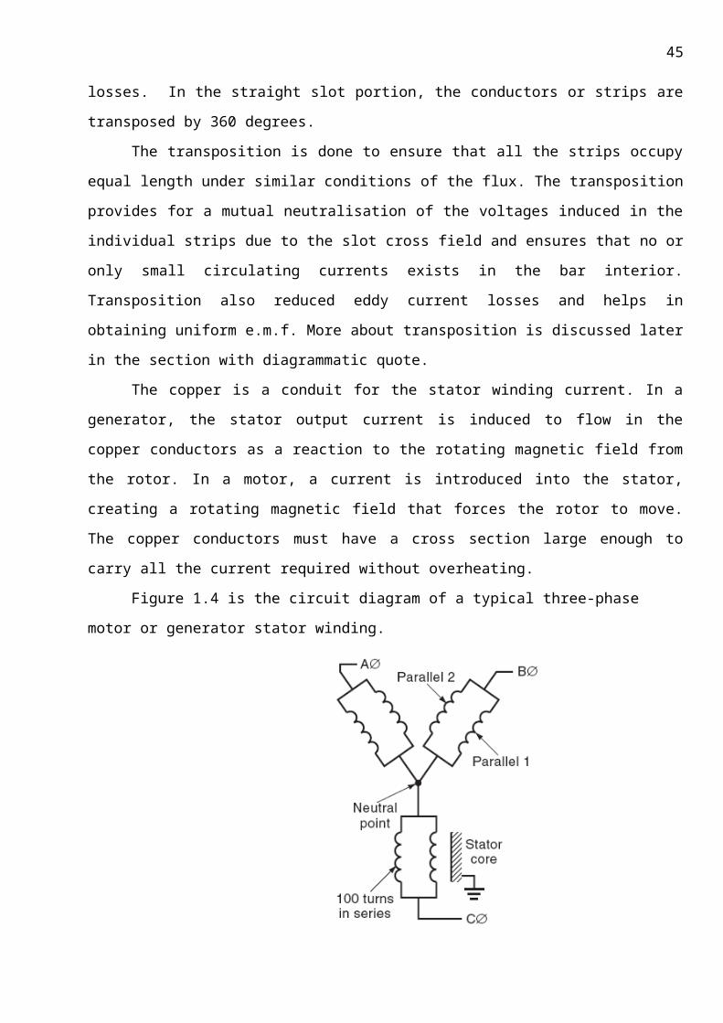
Figure 1.4 is the circuit diagram of a typical three-phase motor or generator stator winding.
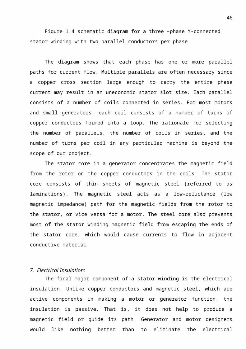
Figure 1.4 schematic diagram for a three –phase Y-connected stator winding with two
parallel conductors per phase
The diagram shows that each phase has one or more parallel paths for current flow. Multiple
parallels are often necessary since a copper cross section large enough to carry the entire phase
current may result in an uneconomic stator slot size. Each parallel consists of a number of coils
connected in series. For most motors and small generators, each coil consists of a number of turns
of copper conductors formed into a loop. The rationale for selecting the number of parallels, the
number of coils in series, and the number of turns per coil in any particular machine is beyond the
scope of our project.
The stator core in a generator concentrates the magnetic field from the rotor on the copper
conductors in the coils. The stator core consists of thin sheets of magnetic steel (referred to as
laminations). The magnetic steel acts as a low-reluctance (low magnetic impedance) path for the
magnetic fields from the rotor to the stator, or vice versa for a motor. The steel core also prevents
most of the stator winding magnetic field from escaping the ends of the stator core, which would
cause currents to flow in adjacent conductive material.
7. Electrical Insulation:The final major component of a stator winding is the electrical insulation. Unlike copper
conductors and magnetic steel, which are active components in making a motor or generator
34
function, the insulation is passive. That is, it does not help to produce a magnetic field or guide its
path. Generator and motor designers would like nothing better than to eliminate the electrical
insulation, since the insulation increases machine size and cost, and reduces efficiency, without
helping to create any torque or current. Insulation is “overhead,” with a primary purpose of
preventing short circuits between the conductors or to ground. However, without the insulation,
copper conductors would come in contact with one another or with the grounded stator core,
causing the current to flow in undesired paths and preventing the proper operation of the machine.
In addition, indirectly cooled machines require the insulation to be a thermal conductor, so that the
copper conductors do not overheat.
The insulation system must also hold the copper conductors tightly in place to prevent
movement. The stator winding insulation system contains organic materials as a primary
constituent. In general, organic materials soften at a much lower temperature and have a much
lower mechanical strength than copper or steel. Thus, the life of a stator winding is limited most
often by the electrical insulation rather than by the conductors or the steel core. Furthermore,
stator winding maintenance and testing almost always refers to testing and maintenance of the
electrical insulation.
35
High purity (99%) copper conductors/strips are used to make the coils. This results in high
strength properties at higher temperatures so that deformations due to the thermal stresses are
eliminated.
36
7.1 STATOR WINDING INSULATION SYSTEM FEATURES
The stator winding insulation system contains several different components and features
which together ensure that electrical shorts do not occur, that the heat from the conductor I 2R
losses are transmitted to a heat sink, and that the conductors do not vibrate in spite of the
magnetic forces.
The basic stator insulation system components are the:
1. Strand (or sub conductor) insulation
2. Turn insulation
3. Ground wall (or ground or earth) insulation
Figures 1.8 and 1.9 show cross sections of random-wound and form-wound coils in a stator slot, and
identify the above components. Note that the form-wound stator has two coils per slot; this is
typical.
Figure 1.10 is a photograph of the cross section of a multi-turn coil. In addition to the main
insulation components, the insulation system sometimes has high-voltage stress-relief coatings and
end-winding support components.
The following sections describe the purpose of each of these components. The mechanical, thermal,
electrical, and environmental stresses that the components are subjected to are also described.
7.1.1 Strand InsulationIn random-wound stators, the strand insulation can function as the turn insulation, although extra
sleeving is sometimes applied to boost the turn insulation strength in key areas. Many form-wound
machines employ separate strand and turn insulation. The following mainly addresses the strand
insulation in form-wound coils and bars. Strand insulation in random wound machines will be
discussed as turn insulation. Section 1.4.8 discusses strand insulation in its role as transposition
insulation.
There are both electrical and mechanical reasons for stranding a conductor in a form wound coil or
bar.
From a mechanical point of view, a conductor that is big enough to carry the current needed in the
coil or bar for a large machine will have a relatively large cross-sectional area. That is, a large
conductor cross section is needed to achieve the desired ampacity. Such a large conductor is
difficult to bend and form into the required coil/bar shape. A conductor formed from smaller
strands (also called sub-conductors) is easier to bend into the required shape than one large
conductor.
37
From an electrical point of view, there are reasons to make strands and insulate them from one
another. It is well known from electromagnetic theory that if a copper conductor has a large enough
cross-sectional area, the current will tend to flow on the periphery of the conductor. This is known
as the skin effect. The skin effect gives rise to a skin depth through which most of the current flows.
The skin depth of copper is 8.5 mm at 60 Hz. If the conductor has a cross section such that the
thickness is greater than 8.5 mm, there is a tendency for the current not to flow through the center
of the conductor, which implies that the current is not making use of all the available cross section.
This is reflected as an effective AC resistance that is higher than the DC resistance. The higher AC
resistance gives rise to a larger I2R loss than if the same cross section had been made from strands
that are insulated from one another to prevent the skin effect from occurring. That is, by making the
required cross section from strands that are insulated from one another, all the copper cross section
is used for current flow, the skin effect is negated, and the losses are reduced.
In addition, Eddy current losses occur in solid conductors of too large a cross section. In the slots,
the main magnetic field is primarily radial, that is, perpendicular to the axial direction. There is also a
small circumferential (slot leakage) flux that can induce eddy currents to flow. In the end-winding,
an axial magnetic field is caused by the abrupt end of the rotor and stator core. This axial magnetic
field can be substantial in synchronous machines that are under-excited.
By Ampere’s Law, or the ‘right hand rule’, this axial magnetic field will tend to cause a current to
circulate within the cross section of the conductor (Figure 1.11). The larger the cross sectional area,
the greater the magnetic flux that can be encircled by a path on the periphery of the conductor, and
38
the larger the induced current. The result is a greater I2R loss from this circulating current. By
reducing the size of the conductors, there is a reduction in stray magnetic field losses, improving
efficiency.
The electrical reasons for stranding require the strands to be insulated from one another. The
voltage across the strands is less than a few tens of volts; therefore, the strand insulation can be
very thin. The strand insulation is subject to damage during the coil manufacturing process, so it
must have good mechanical properties. Since the strand insulation is immediately adjacent to the
copper conductors that are carrying the main stator current, which produces the I2R loss, the strand
insulation is exposed to the highest temperatures in the stator. Therefore, the strand insulation
must have good thermal properties. Section 3.8 describes in detail the strand insulation materials
that are in use. Although manufacturers ensure that strand shorts are not present in a new coil, they
may occur during service due to thermal or mechanical aging (see Chapter 8). A few strand shorts in
form-wound coils/bars will not cause winding failure, but will increase the stator winding losses and
cause local temperature increases due to circulating currents.
39
7.1.1.1.1.1
40
7.1.2 Turn Insulation The purpose of the turn insulation in both random- and form-wound stators is to prevent shorts
between the turns in a coil. If a turn short occurs, the shorted turn will appear as the secondary
winding of an autotransformer. If, for example, the winding has 100 turns between the phase
terminal and neutral (the “primary winding”), and if a dead short appears across one turn (the
“secondary”), then 100 times normal current will flow in the shorted turn. This follows from the
transformer law:
npIp = nsIs (1.1)
Where n refers to the number of turns in the primary or secondary, and I is the current in the
primary or secondary. Consequently, a huge circulating current will flow in the faulted turn, rapidly
overheating it. Usually, this high current will be followed quickly by a ground fault due to melted
copper burning through any ground-wall insulation. Clearly, effective turn insulation is needed for
long stator winding life.
The power frequency voltage across the turn insulation in a random-wound machine can range
up to the rated phase-to-phase voltage of the stator because, by definition, the turns are randomly
placed in the slot and thus may be adjacent to a phase-end turn in another phase, although many
motor manufacturers may insert extra insulating barriers between coils in the same slot but in
different phases and between coils in different phases in the end-windings. Since random winding is
rarely used on machines rated more than 600 V (phase-to-phase), the turn insulation can be fairly
thin. However, if a motor is subject to high-voltage pulses, especially from modern inverter-fed
drives (IFDs), inter-turn voltage stresses that far exceed the normal maximum of 600 Vac can result.
These high-voltage pulses give rise to failure mechanisms, as discussed in Section 8.7.
The power frequency voltage across adjacent turns in a form-wound multi-turn coil is well defined.
Essentially, one can take the number of turns between the phase terminal and the neutral and
divide it into the phase–ground voltage to get the voltage across each turn. For example, if a motor
is rated 4160 Vrms (phase–phase), the phase–ground voltage is 2400V.
This will result in about 24 Vrms across each turn, if there are 100 turns between the phase end and
neutral. This occurs because coil manufacturers take considerable trouble to ensure that the
inductance of each coil is the same, and that the inductance of each turn within a coil is the same.
Since the inductive impedance (XL) in ohms is:
XL = 2_fL (1.2)
Where f is the frequency of the AC voltage and L is the coil or turn inductance, the turns appear as
impedances in a voltage divider, where the coil series impedances are equal. In general, the voltage

41
across each turn will be between about 10 Vac (small form-wound motors) to 250 Vac (for large
generator multi turn coils).
The turn insulation in form-wound coils can be exposed to very high transient voltages associated
with motor starts, IFD operation, or lightning strikes. Such transient voltages may age or puncture
the turn insulation. This will be discussed in Section 8.7. As described below, the turn insulation
around the periphery of the copper conductors is also exposed to the rated AC phase–ground stress,
as well as the turn–turn AC voltage and the phase coil-to-coil voltage.
Before about 1970, the strand and the turn insulation were separate components in multi turn coils.
Since that time, many stator manufacturers have combined the strand and turn insulation. Figure
1.12 shows the strand insulation is upgraded (usually with more thickness) to serve as both the
strand and the turn insulation. This eliminates a manufacturing step (i.e., the turn taping process)
and increases the fraction of the slot cross section that can be filled with copper. However, some
machine owners have found that in-service failures occur sooner in stators without a separate turn
insulation component [1.11].
Both form-wound coils and random-wound stators are also exposed to mechanical and thermal
stresses. The highest mechanical stresses tend to occur in the coil forming process, which requires
the insulation-covered turns to be bent through large angles, which can stretch and crack the
insulation. Steady-state, magnetically induced mechanical vibration forces (at twice the power
frequency) act on the turns during normal machine operation. In addition, very large transient
magnetic forces act on the turns during motor starting or out-of-phase synchronization in
generators. These are discussed in detail in Chapter 8. The result is the turn insulation requires good
mechanical strength.
The thermal stresses on the turn insulation are essentially the same as those described above for
the strand insulation. The turn insulation is adjacent to the copper conductors, which are hot from
the I2R losses in the winding. The higher the melting or decomposition temperature of the turn
insulation, the greater the design current that can flow through the stator.
In a Roebel bar winding, no turn insulation is used and there is only strand insulation. Thus, as will
be discussed in Chapter 8, some failure mechanisms that can occur with multi turn coils will not
occur with Roebel bar stators.
7.1.3 Ground wall InsulationGround wall insulation is the component that separates the copper conductors from the grounded
stator core. Ground wall insulation failure usually triggers a ground fault relay, taking the motor or
generator off-line.* Thus the stator ground wall insulation is critical to the proper operation of a
42
motor or generator. For a long service life, the ground wall must meet the rigors of the electrical,
thermal, and mechanical stresses that it is subject to.
7.1.4 Slot Discharges:
Slot discharges occur if there are gaps within the slot between the surface of the insulation
and that of the core. This may cause ionisation of the air in the gap, due to breakdown of the air at
the instances of voltage distribution between the copper conductor and the iron.
Within the slots, the outer surface of the conductor insulation is at earth potential, in the
overhanging it will approach more nearly to the potential of the enclosed copper. Surface discharge
will take place if the potential gradient at the transition from slot to overhang is excessive, and it is
usually necessary to introduce voltage grading by means of a semi-conducting (graphite) surface
layer, extending a short distance outward from the slot ends.
So insulation of these stator bars is an inevitable task. It is worth now to know about
insulation.
Till now we have discussed the manufacturing process, but the
manufacture is incomplete without insulation design.
7.2 INSULATING MATERIALS:Insulating materials or insulators are extremely diverse in origin and properties. They are
essentially non-metallic, are organic or inorganic, uniform or heterogeneous in composition, natural
or synthetic. Many of them are of natural origin as, for example, paper, cloth, paraffin wax and
43
natural resins. Wide use is made of many inorganic insulating materials such as glass, ceramics and
mica. Many of the insulating materials are man-made products and manufactured in the form of
resins, insulating films etc., in recent years wide use is made of new materials whose composition
and organic substances. These are the synthetic Organo-silicon compounds, generally termed as
silicones.
Properties of a good Insulating Material:
The basic function of insulation is to provide insulation live wire to live wire or to the earth. A
good insulating material needs the following physical and electrical properties.
1. It should be good conductor to heat and bad conductor to electricity.
2. It should withstand the designed mechanical stress.
3. It should have good chemical and thermal resistively and environmental resistively.
4. High dielectric strength sustained at elevated temperatures.
5. High resistivity or specific resistance
6. Low dielectric Hysterisis.
7. Good thermal conductivity.
8. High degree of thermal stability i.e. it should not deteriorate at high temperatures.
9. Low dissipation factor.
10. Should be resistant to oils and liquid, gas flames, acids and alkalis.
11. Should be resistant to thermal and chemical deterioration.
7.2.1 CLASSIFICATION OF INSULATING MATERIAL:
The insulating material can be classified in the following two ways.
I. Classification according to substance and materials.II. Classification according to temperature.
i. Classification according to substance and materials:
1. Solids (Inorganic and organic)
EX: Mica, wood slate, glass, porcelain, rubber, cotton, silks, rayon, ethylene, paper and cellulose
materials etc.
1. Liquids (oils and varnishes)
EX: linseed oil, refined hydrocarbon minerals oils sprits and synthetic varnishes etc.
2. Gases
EX: Dry air, carbon dioxide, nitrogen etc.
44
CLASSIFICATION ACCORDING TO TEMPERATURE:
Class Permissible temperature
Materials
Y 90 Cotton, silk, paper, cellulose, wood etc neither impregnated nor immersed in oil. These are unsuitable for electrical machine and apparatus as they deteriorate rapidly and are extremely hygroscopic.
A 105 Cotton, silk & paper, natural resins, cellulose esters, laminated wool, varnished paper.
E 120 Synthetic material of cellulose base B 130 Mica, asbestos, glass fibre with suitable bonding
substance F 155 Material of class B with binding material of higher thermal
stability. H 180 Glass fibre and asbestos material and built up mica with
silicon resins. C Above
180Mica, porcelain, quartz, glass (without any bonding agent) with silicon resins of higher thermal stability.
7.2.2 INSULATING MATERIALS FOR ELECTRICAL MACHINES:
Name of Material
InsulationClass
Shelf life(In months)
7.2.2.1.1.1.1.1 Application
At20 oC
At 5oc
1. Samicatherm calmica glass-n, mimica, domica, folium, filamic novobond-s, epoxy therm laxman isola calmicaflex
F 6 12 Main insulation of stator bars
2. Samica flex H 4 8 Overhang insulation of motor coils, at 3rd bends of multi turn coil
3. Vectro asbestos (365.02/365.32)
4. (used in resin rich)
B/F 2 8 Main pole coils of synchronous machines
5. Epoxide impregnated glass cloth 7.2.2.1.1.1.2
F
6 12 Winding holders and inter-half insulation
6. Polyester resin mat & rope
6 Bar to winding holder & stiffener groove of support segment of
45
clamping plate7. Glassoflex
Turbo laminateF 6 12 Inter-turn insulation of
rotor winding8. Hyper seal tape F 6 12 As finishing layer in
overhangs of motor coils
9. SIB775 or 4302 varnish F 6 12 Stack Consolidation of stator bars
10. SIB475 or 4301 varnish F 6 12 Base coat varnish before taping of stator bars
11. SIB 643 or8003 Varnish or K8886 varnish
4 8 Conductive coat in straight portion of stator bars
12. SIB 642 or 8001 varnish 4 8 At slot emerge portion on stator bars
7.3 FEW DEFINITIONS OF ELECTRIAL PROPERTIES OF INSULATION:
7.3.1 INSULATON RESISTANCE:It may be defined as the resistance between two conductors usually separated by insulating
materials. It is the total resistance in respect of two parallel paths, one through the body and
other over the surface of the body.
Insulation Resistance is influenced by the following factors.
1) It falls with every increase in temperature.
2) The sensitivity of the insulation is considerable in the presence of moisture.
3) Insulation resistance decrease with increase in applied voltage.
7.3.2 DIELECTRIC STRENGTH: The voltage across the insulating material is increased slowly the way in which the leakage
current increases depend upon the nature and condition material.
7.3.3 POWER FACTOR:Power factor is a measure of the power losses in the insulation and should be low. It varies
with the temperature of the insulation. A rapid increase indicates danger.
7.3.4 DIELECTRIC CONSTANT:This property is defined as the ratio of the electric flux density in the material .To that
produced in free space by the same electric force.
46
7.3.5 DIELECTRIC LOSS:The dielectric losses occur in all solid and liquid dielectric due to
(b) Conduction current
(c) Hysterisis.
Additional to the Electrical properties there are many factors such as thermal, chemical etc.., they
are tabulated as below.
S.No Thermal Properties Chemical Properties Mechanical Properties
1.
2.
3.
4.
5.
6.
7.
Specific heat
Thermal conductivity.
Thermal plasticity
Ignitability
Softening point
Heat Aging
Thermal expansion.
Resistance to external chemical
effects.
Resistance to chemical in soils.
Effect of moisture and water.
Density
Viscosity
Moisture absorption
Hardness of surface
Surface tension
Uniformity.
8. Resin Impregnation:
Resin impregnation fills the porosity of a part with a resin to create a pressure-tight part for
hydraulic applications which can withstand several thousand psi, to improve machine ability, or to
allow electroplating. The parts are placed in a mesh basket and loaded into a vacuum tank. This is
then submerged in a bath of Anaerobic resin. A vacuum is pulled to remove all air from the porosity
of the parts. This vacuum is released to and the tank is pressurised, causing the resin to be drawn
into the porosity of the parts. Parts that typically undergo resin impregnation include hydraulic
fittings for pressure tightness and plating, covers and plated for pressure tightness, as well as
machined components.
The previous method of sealing parts was a furnace treatment, which formed a hard oxide layer
on the internal and external surfaces of a part, filling the porosity. Most machining operations were
performed prior to sealing the part because the hard oxide layer adversely affected mach inability.
Residue left by traditional cutting fluids tended to inhibit the formation of an oxide layer. With resin
impregnation, conventional cutting fluids can be used because the furnace treatment is eliminated
47
resulting in improved mach inability. These fluids efficiently remove heat from the cutting tool,
extending the tool life. Machining a porous part effectively creates a continuous interrupted cut.
Each time the tool impacts metal after passing through a pore, it may chip and become dull. Resin
impregnation reduces that effect and may also provide added lubrication to the cutting tool. Before
resin impregnation, many parts were mechanically plated. Resin impregnation allows the use of
electroplating.
EPOXY RESINS:Epoxy resins are poly ethers derived from epi-chloro hydrin and Bis-phenol
monomers through condensation polymerization process. These resins are product of alkaline
condensed of epi-chloro hydrin and product of alkaline condensed of epi-chloro hydrin and poly-
hydric compounds.
In epoxy resins cross-linking is produced by cure reactions. The liquid polymer has reactive
functional group like oil etc, otherwise vacuum as pre polymer. The pre polymer of epoxy resins
allowed to react curing agents of low inductor weights such as poly-amines, poly-amides, poly-
sulphides, phenol, urea, formaldehyde, acids anhydrides etc, to produce the three dimensional cross
linked structures.
Hence epoxy resins exhibit outstanding toughness, chemical inertness and excellent
mechanical and thermal shock resistance. They also possess good adhesion property. Epoxy resins
can be used continuously up to 300F, but with special additions, the capability can be increased up
to a temperature of 500F.
Epoxy resins are made use as an efficient coating material. This includes coating of tanks
containing chemicals, coating for corrosion and abrasion resistant containers. Epoxy resins are made
up of as attractive corrosion and wear resistant floor ware finishes.
These are also used as industrial flooring material. They are also used as highways Surfacing
and patching material. Moulding compounds of epoxy resins such as pipe fitting electrical
components bobbins for coil winding and components of tooling industrial finds greater application
in industries.
The epoxy resins similar to polyester resins can be laminated and Fibre Reinforced (FPR) and
used in glass fibre boats, lightweight helicopters and aeroplanes parts.
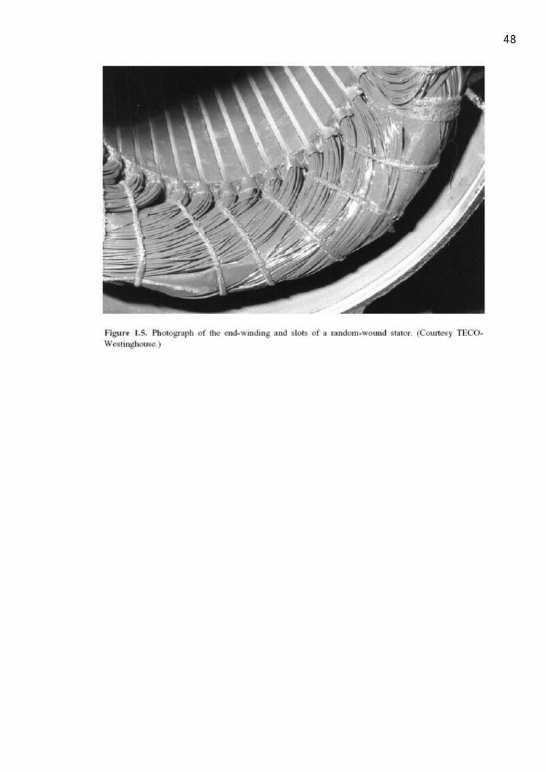
48
In the modern electronic industry, the application of epoxy resins is great. Potting and
encapsulation (coating with plastic resin) is used for electronic parts. Most of the printed circuits
bodies are made of laminated epoxy resin which is light but strong and tough.
PROPERTIES:
1) Epoxy resins have good mechanical strength less shrinkage and excellent dimensional stable after casting.
2) Chemical resistance is high.
3) Good adhesion to metals.
4) To impact hardness certain organic acid anhydrides and alphabetic amines are mixed.
APPLICATIONS:
1) They are used in the manufacture of laminated insulating boards.
2) Dimensional stability prevents crack formation in castings.
3) They are also used as insulating varnishes.
8.1INSULATING MATERIAL FOR LAMINATIONS: -
The core stacks in modem machines are subjected to high pressers during assembly and
there fore to avoid metal-to-metal contact, laminations must be well insulated. The main
requirements of good lamination insulation are homogeneously in thin layers toughness and high
receptivity.
We use varnish as insulating material for laminations.
8.2 VARNISH
This is most effective type of insulation now available. It makes the laminations nest proofs
and is not affected by the temperature produced in electrical machines varnish is usually applied to
both sides of lamination to a thickness of about 0.006mm. On plates of 0.35mm thickness varnish
gives a stacking factor about 0.95.In order to achieve good insulation properties the following
processes are in BHEL.
THERMOPLASTIC PROCESS OF INSULATION THERMOSETTING PROCESS OF INSULATION
BHEL is practicing only thermosetting process of insulation so
Thermosetting types of insulation are of two types:
49
RESIN RICH SYSTEM OF INSULATION
RESIN POOR SYSTEM OF INSULATION
The various types of materials used in the resin rich and resin poor process are given below.
Let us have an overview.
8.3 Materials used in resin poor system:
MATERIAL FOR RESIN POOR
DIAMOND COILS HALF BARS
Treated trivoltherm Impregnated polyester fleece Glass mat with accelerator Hostofon folium Synthetic fibre tape Resin poor mica tape Polyester fleece tape with graphite Semiconductor asbestos tape Polyester glass tape Polyester fleece tape Nomex polyamide adhesive tape
EPOXY glass cloth Nomex glass fleece Fine mica polyester glass cloth Nomex Form micanite Form mica tape Copper foil Polyester fleece tape with graphite for ICP Polyester fleece for OCP Polyester fleece tape with silicon
carbide Mica splitting tape
VARNISH
Polyester glass tape Rutapox Hardener (H-90)
Materials used in resin rich process:
MATERIAL FOR RESIN RICH BARS:
Preprag Nomex Epoxy resin rich mica tape Glass tape PTFE tape
50
VARNISH
Mica powder Graphite powder Conductive varnish Semiconductor varnish
8.4 RESIN RICH SYSTEM:
In olden days, Resin Rich system of insulation is used for all Electrical Machines. In insulator
contains nearly 40% of EPOXY RESIN, so it gives good thermal stability Resin Rich Insulation consists
of the following materials in percentage
1. MICA PAPER TAPE -40-50%
2. GLASS PAPER TAPE-20%
3. EPOXY RESIN-40%
The bars are insulated (or) taped with RESIN RICH TAPE and place in the Pre-assembled
stator core including stator frame.
In resin rich system of insulation Mica paper will give a good dielectric strength and Glass fiber tape
will give a good mechanical strength and Epoxy resin can withstand up to 155 degree Centigrade so
it gives a good thermal properties. Resin rich and Resin poor insulating materials are characterized
by the contact of the Epoxy Resin. In Resin rich system the content of Epoxy Resin tape is 40% so it is
named as RESIN RICH SYSTEM, and in Resin poor system the content of Resin tape is 8%. By VIP
impregnation process, the required amount is added to then conductor bars after assembling the
core and placing the winding in the core. In resin rich system before placing of coils in the stator
slots the rich tape will be wrapped over the bars. Nevertheless, this system has the following
disadvantages:
1. This system is very time consuming and very long procedure.
2. Total cost of the system is more.
In order to minimize the over all cost of the machine and to reduce the time cycle of the system, the
VACUUM PRESSURE IMPREGNATION SYSTEM is being widely used. This process is very simple, less
time consuming and lower cost.
BHEL, HYDERABAD is equipped with the state of the art technology of VACUUM PRESSURE
IMPREGNATION.
The core or coil building and assembling method depends on the insulation system used. The
difference in core building is
1. For Resin rich insulation system the laminations are stacked in the frame itself.
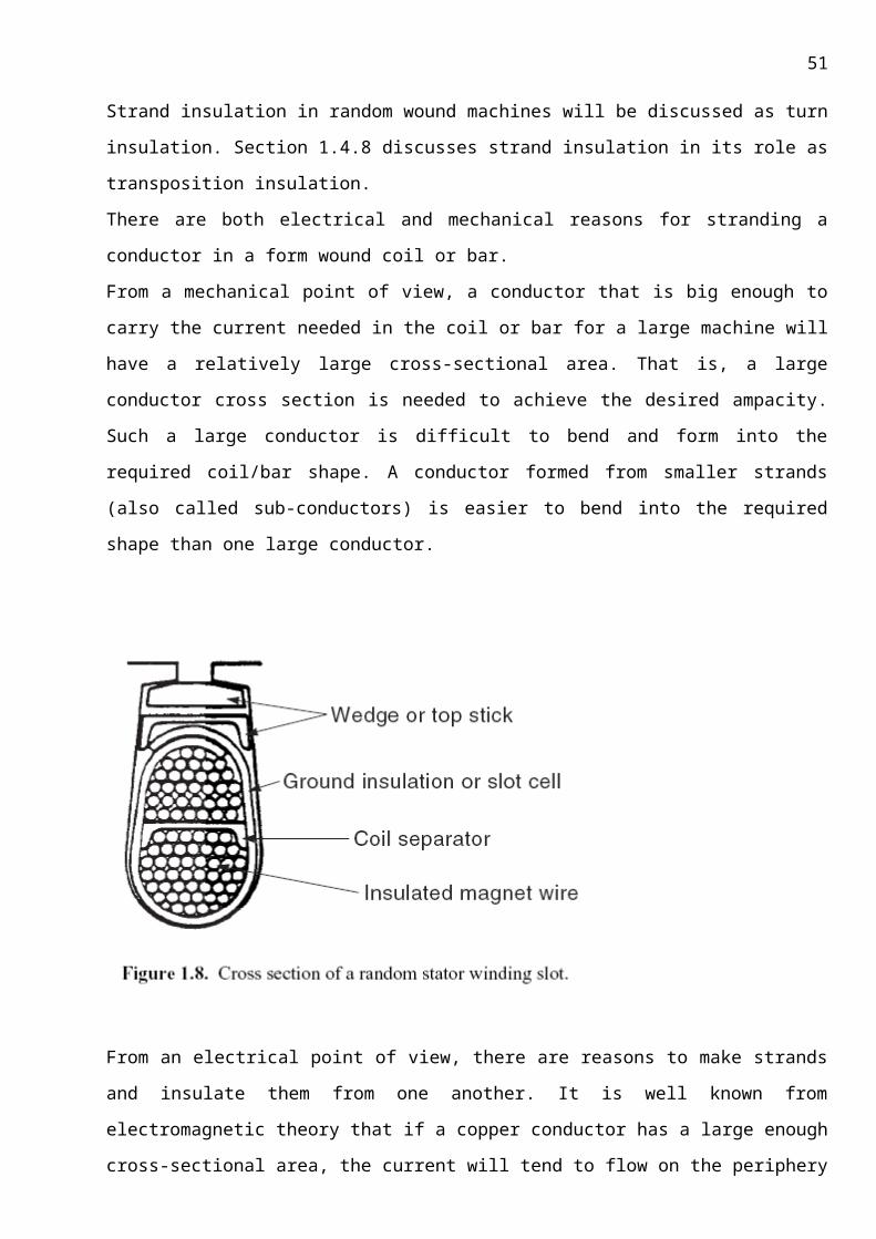
51
2. For Resin poor insulation system (VPI) cage core of open core design is employed.
The manufacturing of coils also differs for both as explained above for core.
1. For resin poor process
2. For resin rich process
13.2.1.1.1.1MANUFACTURE OF STATOR COILS:
Manufacturing of stator coils depends on the type of the insulation process used for the
stator. I.e. the process is different for resin rich and resin poor process although few of the sub
processes are same for both.
9.1 For resin poor process:
In this process the high voltage insulation is provided according to the resin poor mica base of
thermosetting epoxy system. Several half overlapped continuous layers of resin poor mica tape
are applied over the bars. The thickness of the tape depends on the machine voltage.
9.1.1 Reception of copper conductors:
The copper conductors rolls are received is checked for physical and mechanical properties. First
piece is checked for specifications such as length and if found satisfactory, mass cutting to desired
length is carried out by feeding into the cutting mills.
9.1.2 Transposition:
Conductors are adjusted one over another for a given template and the bundles are
transposed by 360 degrees by setting the press for “Roebel Transposition”. Now they are bundled
and consolidated by tying with cutter
tape at various places.
Similarly all the bundles are
processed. Thus each stator bundle
has a transposed coils in each phase
such that the flux distribution is equal
and hence the induced e.m.f.
Figure 4: Side View showing one way of transposing insulated strands in stator bar.
9.1.3 Putty operation:
All the transposed bars are shifted to putty operation. Here a single bar is taken for putty
operation by filling up the uneven surfaces on the width face by filling with NOMAX. I.e., NOMAX
52
sheets are inserted in the crossovers on the width face to the both ends. Form mica net is placed
over the width face of the bar on both sides & wrapped with PTFE (poly tetra flamo ethane) tape.
9.1.4 Stack consolidation:
Now 2 to 3 bars are inserted into hydraulic presser and they are pressed horizontally and
vertically to a pressure up to 150kg/cm2. At the same time the bars are subjected o heating from
140 to 160 degrees for duration of 2-3 hrs. Then the bars are unloaded and clamped perfectly. Now
inter half and inter strip testing is carried out and the dimensions are checked using a gauge.
9.1.5 Bending:
Each of the samples is placed over the universal former & the universal former is aligned to
the specifications. The bar is bent on both the sides i.e. on turbine side (TS) and exciter side
(ES).the 1st bend and the 2nd bend is carried out and continued by over hang formation. Now the
3rd bend is carried by inserting nomax sheet from the end of straight part to the end of 3 rd bend
and the bars are clamped tightly. Now the clamps are heated to 60 degrees for 30mins. Inter
half and inter strip tests follows.
9.1.6 Final taping:
The taping may be machine or manual taping and the taping is done according to the
type of insulation used. In case of resin poor system, resin poor tape is wrapped by 9*1/2 over
lap in the straight portion up to overhang and 6*1/2 over lap layers in the intermittent layers.
The intermittent layers are follows….
1st intermittent layer is ICP (internal corona protection) tape. This is wrapped by
butting only in straight portion.
2nd is split mica tape. One layer of split mica is wrapped by butting & using conductive
tape at the bottom so that split mica is not overlapped.
Next layer is O.C.P (outer corona protection). OCP tape is wrapped final in straight
portion by but joint up to end of straight portion on both the sides.
Next intermittent layer is ECP (end corona protection). ECP tape is wrapped from the
end of straight portion up to over hang over a length of 90-110mm. Now the bars are wrapped
finally with hyper seal tape from straight portion to the end of 3 rd bend in overlapping layers for
protecting the layers from anti fingering. The IH & IS tests follows and the bars are discharged to
the stator winding.
53
Fig 2. Cross-section of a multi turn coil, where three turns and three strands per turn.
9.2 For Resin rich system:
The coil manufacture is same as in case of resin poor but differ in a few stages. The
Conductor cutting and material used is same as resin poor system. Transposition is done same as
that of resin poor system. Stacking of coils is done. In this case high resin glass cloth is used for
preventing inter half shorts. There is a difference in putty work.
9.2.1 Putty work:
Nomex is used in between transposition pieces. 775 varnish is applied over the straight portion of
bar and mica putty is applied on the width faces of the bars.
Mica Putty mixture is a composition of SIB 775 Varnish, mica powder and china clay in the ratio of
100:50:25.
Straight part baking is done for 1hour at a temperature of 160C and a pressure of
150kg/sq.cm.Then bending and forming is done. Half taping with resin rich tape is done for over
hangs and reshaping is done. To ensure no short circuits half testing of coils is done.
9.2.2 Final taping:
Initial taping and final tapings is done with resin rich tape (semica therm tape) to about 13-
14 layers. The main insulation layers are 12*1/2 overlap in the straight portion and 9 layers in the
overhang.
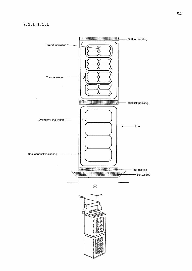
54
Figure 3: Layout of a mould used in baking of stator by Resin rich process
9.2.3 Final baking:
Final baking is done for 3hrs at a temperature of 160C in cone furnace. The bar is fed into
the baking mould.
The bar is heated for 1 hr at 90 degree to get gelling state.
The temperature of the mould is increased to 110 degrees in 30 mins and simultaneously the
moulds are tightened. Now in this process 155 of the resin is oozed out only 25% will be
remain. Now the bar is unloaded and checked for final dimensions, sharp corners,
depressions, charring, hollow sounds etc.,
Gauge suiting is done. I.e. the dimensions are made to compromising with the design.
Conductive/graphite coating (643) is applied on the straight portion and semi-conductive
coating 642 from end of straight portion to 3rd bend to pre transition coating on both
sides.1st coating for 90mm, 2nd coating for 100mm and 3rd coating for 120mm on both sides.
The bar is allowed for drying and epoxy red gel is applied from the end of straight portion to
the 3rd bend on both sides and allow for drying.
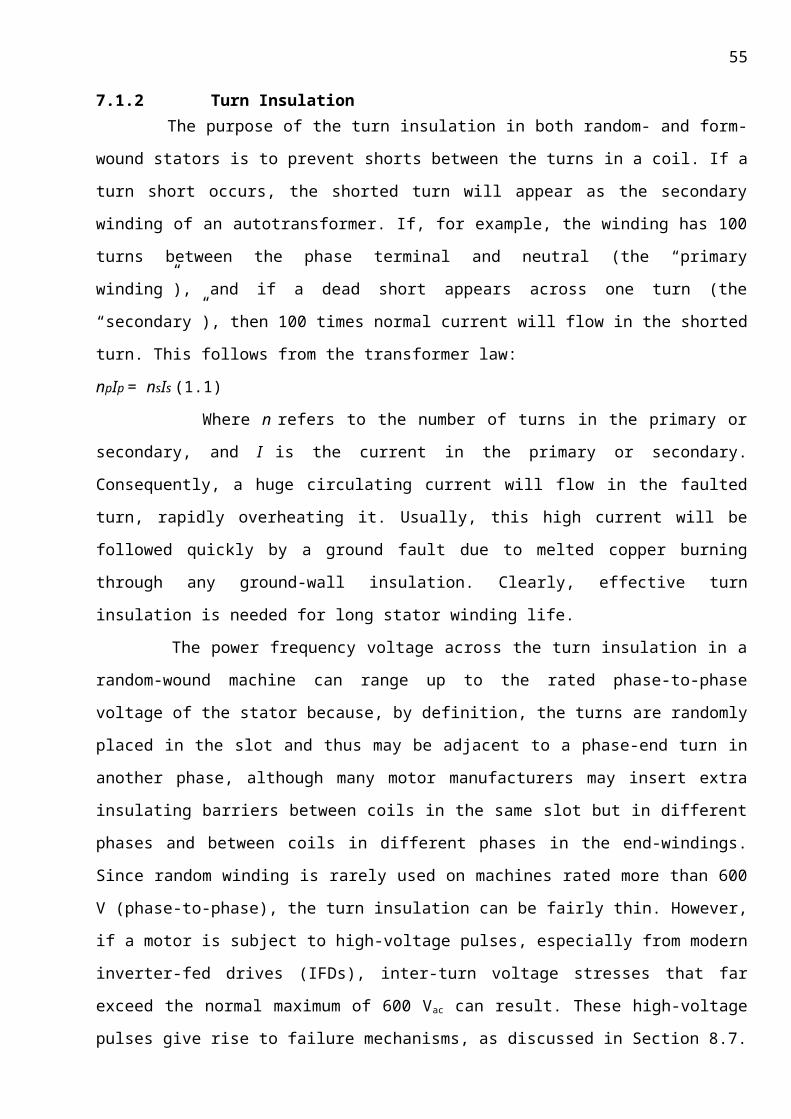
55
High voltage testing is done at 4 times that of rated voltage and tan testing, inter strip, inter
half testing are done. Tan values must be less than 2%.
10. An overview
10.1 ADVANTAGES OF RESIN POOR SYSTEM OF INSULATION:
It has better dielectric strength
Heat transfer coefficient is much better
Maintenance free and core and frame are independent
It gives better capacitance resulting in less dielectric losses due to which the insulation life will
be more
The cost will be less and it is latest technology
Reduction in time cycle and consumption for MW also less and it gives high quality
10.2 DISADVANTAGES OF RESIN POOR SYSTEM OF INSULATION:
If any short circuit is noticed, the repairing process is difficult and need of excess resin from
outside.
Dependability for basic insulating material on foreign supply
10.3 ADVANTAGES OF RESIN RICH SYSTEM OF INSULATION:
Better quality and reliability is obtained
In case of any fault (phase - ground/ phase – phase short) carrying the repair process is very
easy.
Addition of excess resin will be avoided because of using resin rich mica tape
10.4 DISADVANTAGES OF RESIN RICH SYSTEM OF INSULATION:
It is a very long procedure
Due to fully manual oriented process, the cost is more
It is possible to process stator bars only.
Even though the advantages and disadvantages of both the process are explained above, resin
poor process is the best of all, as the resin content used is almost only 35% compared to resin poor
process and also show good insulation properties justified later.
11. Assembly of stator:
The completed core and the copper bars are brought to the assembly shop for
assembly.
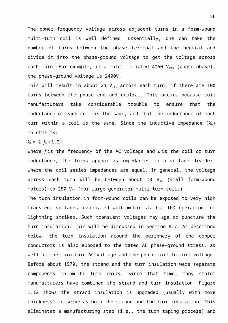
56
11.1 Reception of stator core:
Stator core after the core assembly is checked for the availability of foreign matter, so coil
projections are checked in each slot. HGL gauge is passed in each and every slot to detect bottom
core projections.
11.2 Winding holder’s assembly:
Assemble all the winding holders on both sides by adapting to the required design size.
Check all the wedge holders by a template and they are assembled as per the design requirement.
Tighten all the bolts relevant to winding holders and lock them by tag welding. Assemble HGL rings
on both the sides by centring with respect to core. Subject each individual for pressing in pressing
fixture at a pressure of 60 kg/cm2 for 30 minutes. Inter half test is conducted for each individual bar
before assembling into the stator.
Now stator bar assembling is carried out by centring to the core and check for proper
seating of bottom bars with T-gauge and checked for third bend matching, over hang seating etc..,
rein force the overhang portion of stator bars by inserting glass mat in between the bars and tying
them with neoprene glass sleeve. This process is carried out for all respective bottom bars .now the
pitch matching is checked on both sides both the generator and the exciter side.
Now high voltage testing is carried out on the stator.
11.3 Stiffeners assembly: Stiffeners are assembled on both sides and then checked for physical feasibility of top bar
by laying into the respective slot. Check for uniform gap in the over hang and top bar matching to
the bottom bar pitch on both sides. Assemble all the top bars by inserting inner layer inserts and
also assemble relevant RTD’s (Resistance Temperature detectors) where ever they are required as
per the design.
After completion of top bars, reinforce overhangs by inserting Glass-mat and tying with
Neoprene glass sleeve and also check for the third bend matching on both the sides. Then the core
is subjected to high voltage DC test and inter half short circuit tests.
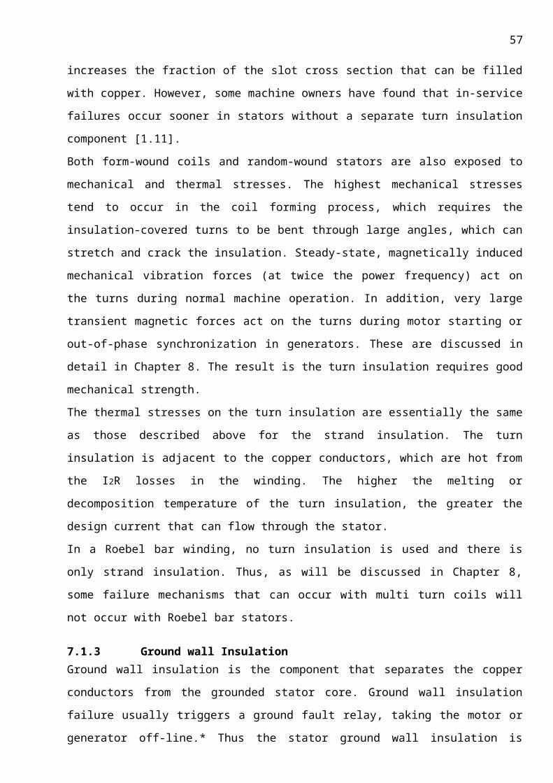
57
11.4 Eye formation: Join bottom conductors and top conductors forming an eye, by brazing the conductors with
silver foil. Segregate eyes into two halves on both sides and test for inter half shorts. Insert Nomax
into two halves and close them.
Brazing makes the electrical connection between the top and bottom bars. One top bars
strand each is brazed to one strand of associated bottom bar so that beginning of the strand is
connected with out any electrical contact with the remaining strand. This connection offers the
advantage of minimising three circulating currents.
11.5 Connecting rings assembly: The connecting rings are assembled on exciter side as per the drawing and connect all the
connectors to the phase groovers by joining and brazing with silver foil. Clean each individual phase
groove, insert nomax sheet and tape with semica folium. Subject the whole stator for HVDC test.
Terminate the three RTD’s in the straight portion and the 3-RTD’s in the over hang portion on both
turbine and exciter side except one for earthing requirement.
11.6 Phase connectors: The phase connectors consist of flat copper sections, the cross section of which results in a
low specific current loading. The connections to the stator winding are of riveted and soldered tape
and like wise wrapped with dry mica/glass fabric tapes. The phase connectors are firmly mounted
on the winding support using clamping pieces and glass fabric tapes.
Thus we have a completed stator here. Now this stator is sent for VPI process because in there is a
chance of damage to the insulation due to the following reasons
During the stator assembly, the bars are beaten with rubber hammers to fit into the slots
Also there is a chance of void spaces in between the stator conductors and the core due to
the use of solid insulating materials, which lead to slot discharges.
So in order to fill these voids and to gain good insulating properties the stator is VPI processed. Let
us start with an introduction to the process and the early materials used for this process and the
advancement of this process to our present resin poor VPI process.
12. The vpi process
12.1 INTRODUCTION TO VACUUM PRESSURE IMPREGNATION SYSTEM (VPI)

58
12.2 HISTORY
DR. MEYER brought the VPI system with the collaboration of WESTING HOUSE in the year
1956. Vacuum Pressure Impregnation has been used for many years as a basic process for thorough
filling of all interstices in insulated components, especially high voltage stator coils and bars. Prior to
development of Thermosetting resins, a widely used insulation system for 6.6kv and higher voltages
was a Vacuum Pressure Impregnation system based on Bitumen Bonded Mica Flake Tape is used as
main ground insulation. After applying the insulation coils or bars were placed in an autoclave,
vacuum dried and then impregnated with a high melting point bitumen compound. To allow
thorough impregnation, a low viscosity was essential. This was achieved by heating the bitumen to
about 180C at which temperature it was sufficiently liquid to pass through the layers of tape and fill
the interstices around the conductor stack. To assist penetration, the pressure in the autoclave was
raised to 5 or 6 atmospheres. After appropriate curing and calibration, the coils or bars were wound
and connected up in the normal manner. These systems performed satisfactorily in service provided
they were used in their thermal limitations. In the late 1930’s and early 1940’s, however, many large
units, principally turbine generators, failed due to inherently weak thermoplastic nature of bitumen
compound.
Failures were due to two types of problems:
a. Tape separation
b. Excessive relaxation of the main ground insulation.
Much development work was carried out to try to produce new insulation systems, which
didn’t exhibit these weaknesses. The first major new system to overcome these difficulties was
basically a fundamental improvement to the classic Vacuum Pressure Impregnation process. Coils
and bars were insulated with dry mica flake tapes, lightly bonded with synthetic resin and backed by
a thin layer of fibrous material. After taping, the bars or coils were vacuum dried and pressure
impregnated in polyester resin. Subsequently, the resin was converted by chemical action from a
liquid to a solid compound by curing at an appropriate temperature, e.g. 150 C. this so called
thermosetting process enable coils and bars to be made which didn’t relax subsequently when
operating at full service temperature. By building in some permanently flexible tapings at the
evolutes of diamond shaped coils, it was practicable to wind them without difficulty. Thereafter,
normal slot packing, wedging, connecting up and bracing procedures were carried out. Many
manufacturers for producing their large coils and bars have used various versions of this Vacuum
Pressure Impregnation procedure for almost 30 years. The main differences between systems have
been in the types of micaceous tapes used for main ground insulation and the composition of the
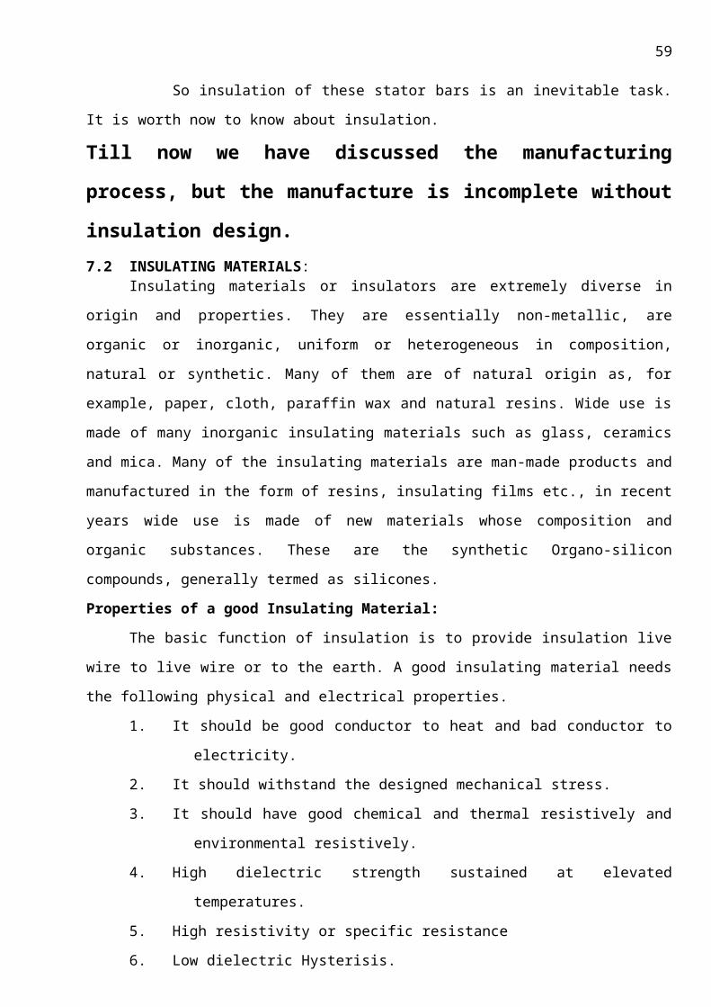
59
impregnated resins. Although the first system available was styrenated polyester, many
developments have taken place during the last two decades.
Today, there are several different types of epoxy, epoxy-polyester and polyester resin in
common use. Choice of resin system and associated micaceous tape is a complex problem for the
machine manufacturer.
Although the classic Vacuum Pressure Impregnation technique has improved to a significant
extent, it is a modification to the basic process, which has brought about the greatest change in the
design and manufacture of medium-sized a.c. industrial machines. This is the global impregnation
process. Using this system, significant increases in reliability, reduction in manufacturing costs and
improved output can be achieved. Manufacture of coils follows the normal process except that the
ground insulation consists of low-bond micaceous tape. High-voltage coils have corona shields and
stress grading applied in the same way as for resin-rich coils, except that the materials must be
compatible with the Vacuum Pressure Impregnation process. Individual coils are inter turn and high-
potential-tested at voltages below those normally used for resin-rich coils because, at the un-
impregnated stage, the intrinsic electric strength is less than that which will be attained after
processing. Coils are wound into slots lined with firm but flexible sheet material. Care has to be
taken to ensure that the main ground insulation, which is relatively fragile, is not damaged. After
inter-turn testing of individual coils, the series joints are made and coils connected up into phase
groups. All insulation used in low-bond material, which will soak up resin during the impregnation
process. End-winding bracing is carried out with dry, or lightly treated, glass-and/or polyester-based
tapes, cords and ropes. On completion, the wound stator is placed in the Vacuum Pressure
Impregnation tank, vacuum-dried and pressure-impregnated with solvent less synthetic resin.
Finally, the completed unit is stoved to thermo set all the resin in the coils and the associated
bracing system.
After curing, stator windings are high-potential-tested to the same standard. Loss-tangent
measurements at voltage intervals up to line voltage are normally made on all stators for over 1kv.
A major difference between resin-rich and vacuum pressure impregnation lies in the importance of
this final loss-tangent test; it is an essential quality-control check to conform how well the
impregnation has been carried out. To interpret the results, the manufacturer needs to have a
precise understanding of the effect of the stress-grading system applied to the coils. Stress grading
causes an increase in the loss-tangent values. To calculate the real values of the ground insulation
loss-tangent, it is necessary to supply from the readings the effect of the stress grading. For grading
materials based on the materials such as silicon carbide loaded tape or varnish, this additional loss
depends, to a large extent upon the stator core length and machine voltage.
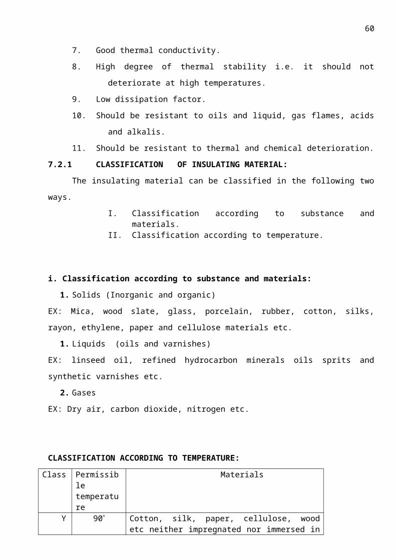
60
VPI is a process, which is a step above the conventional vacuum system. VPI includes pressure
in addition to vacuum, thus assuring good penetration of the varnish in the coil. The result is
improved mechanical strength and electrical properties. With the improved penetration, a void free
coil is achieved as well as giving greater mechanical strength. With the superior varnish distribution,
the temperature gradient is also reduced and therefore, there is a lower hot spot rise compared to
the average rise.
In order to minimise the overall cost of the machine & to reduce the time cycle of the
insulation system vacuum pressure Impregnated System is used. The stator coils are taped with
porous resin poor mica tapes before inserting in the slots of cage stator, subsequently wounded
stator is subjected to VPI process, in which first the stator is vacuum dried and then impregnated in
resin bath under pressure of Nitrogen gas.
The chemical composition of our resin type and its advantages are explained in the later
sections. Now let us discuss the various stages involved in VPI process for resin poor insulated jobs.
VPI process is done in the VPI camber. For higher capacity stators of steam turbine or gas
turbine generator stators, horizontal chamber is used where as vertical chamber is used for smaller
capacity systems such as Permanent Magnet Generator (PMG), coil insulation of small pumps and
armature of motors etc..,
12.3 Vacuum Pressure Impregnation of resin poor insulated
jobs:
VPI process for a stator involves the following stages.
2. Preheating
3. Lifting and shifting
4. Vacuum cycle
5. Vacuum drop test
6. Heating the resin
7. Resin admission.
8. Resin settling
9. Pressure cycle
10. Aeration.
11. Post curing cycle
12. Cleaning
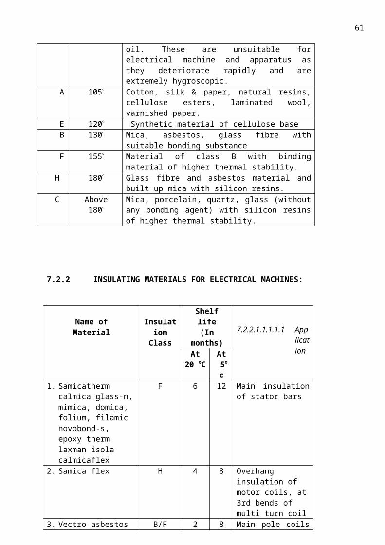
61
12.3.1 General instructions before VPI process:
The jobs that are entering tank for Vacuum Pressurised Impregnation shall not have any oil
based coatings. Any such, rust preventive/ corrosion preventive viz., red oxide etc., shall be
eliminated into the tank. Jobs shall be protected with polyethylene sheet for preventing dust or dirt
on jobs, till it is taken up for impregnation. Resin in the storage tank shall be stored at 10 to 12 C
and measured for its viscosity, viscosity rise. Proper functioning of the impregnation plant and
curing oven are to be checked by production and cleared for taking up of job for impregnation.
12.3.2 Pre heating:
The foremost stage of VPI, the completed stator is placed in the impregnation vessel and
kept in an oven for a period of 12 hours at a temperature of 60 deg. Six thermocouples are inserted
at the back of the core to measure the temperature. The temperature should not exceed to 85
deg .Smaller stator can be inserted directly into the impregnation chamber. The job is to be loaded
in the curing oven and heated. The temperature is to be monitored by the RTD elements placed on
the job and the readings are logged by production. The time of entry into the oven, time of taking
out and the temperature maintained are to be noted. Depending on convenience of production the
jobs can be preheated in impregnation tank by placing them in tubs.
The impregnation tubs used for impregnation of jobs are to be heated in the impregnated tank
itself, when the jobs are preheated in the curing oven
Insertion of tub with job into the impregnation tank:
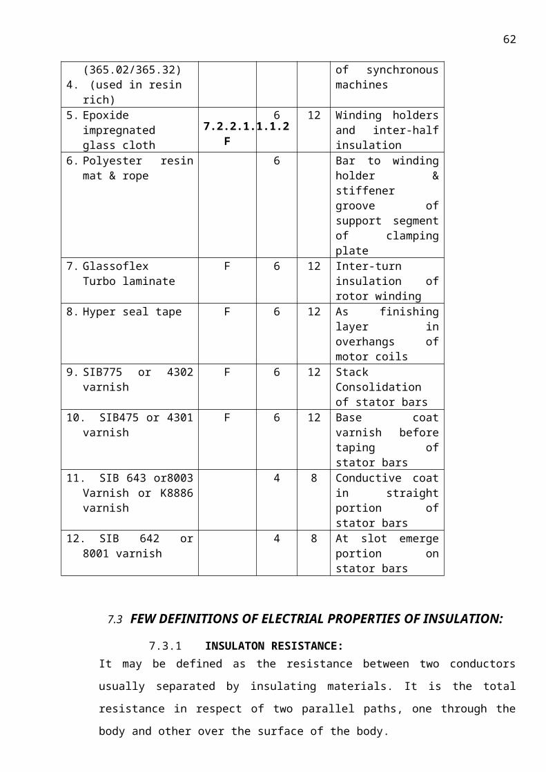
62
The wound stator is lifted and shifted into the tub. By the time, the preheating of job is completed, it is to be planned in such a way that the heating of tub and tank heating matches with the job. This is applicable when the job is heated in the curing oven separately. The preheated job is to be transferred into the tub by crane handling the job safely and carefully with out damage to the green hot insulation the tub is then pushed in the 140 tank furnace or also called as vacuum tank, after which the lid is closed and the tank furnace was heated to 60 +/- 3 deg The warm tub with job is inserted into impregnation tank by sliding on railing, in case of horizontal tank. The thermometer elements are to be placed at different places on the job. The connection for inlet resin is to be made for collection of resin into tub. After ensuring all these lid of the impregnation tank is closed. In case of vertical tank the job along with tub is slinged and inserted carefully into impregnation tank without damage to insulation
12.3.3 Vacuum cycle:
The pre heated job will be placed in the impregnation chamber by a hydraulic mechanism.
The vessels are kept clean and the resin available in the vessel is wiped out. Methylene and traces of
resin should not be allowed on the inner side of the tank. Now the vacuum pumps are all switched
on and a vacuum pressure of about 0.2 mb is maintained for about 17 HRS, after which the wound
stator is subject to vacuum drop test.
Vacuum drop test:
This drop test is important phase, all the vacuum pumps are switched off for about 10 mins,
and the vacuum drop is measured and it is checked whether it exceeds 0.06mb, if it exceeds 0.06mb
then it is subject to repetition of vacuum cycle for another 6 to 8 hrs, else it is sent to the next cycle
Drying the job in vacuum
The job is to be dried under vacuum. Drain out the condensed moisture/ water at the
exhausts of vacuum pumps for efficient and fast vacuum creation. Also check for oil replacement at
pumps in case of delay in achieving desired vacuum.
12.4 resin management
Heating the resin in the storage tank
The completion of operations of drying and the heating of the resin in the storage tank are to
be synchronised. The heating of resin in the tank and pipeline is to be maintained as at preheating
temperature .i.e. the temperature is maintained at 60+/- 3 deg ,including pipeline
Admission of resin into impregnation tank
The resin is allowed into the impregnation tank tub if required from various storage tanks
one after the other, such that the difference in pressure fills the tank, up to a level of 100mm above
the job generally, after which the resin admission is stopped. After 10mins of resin settling the tank
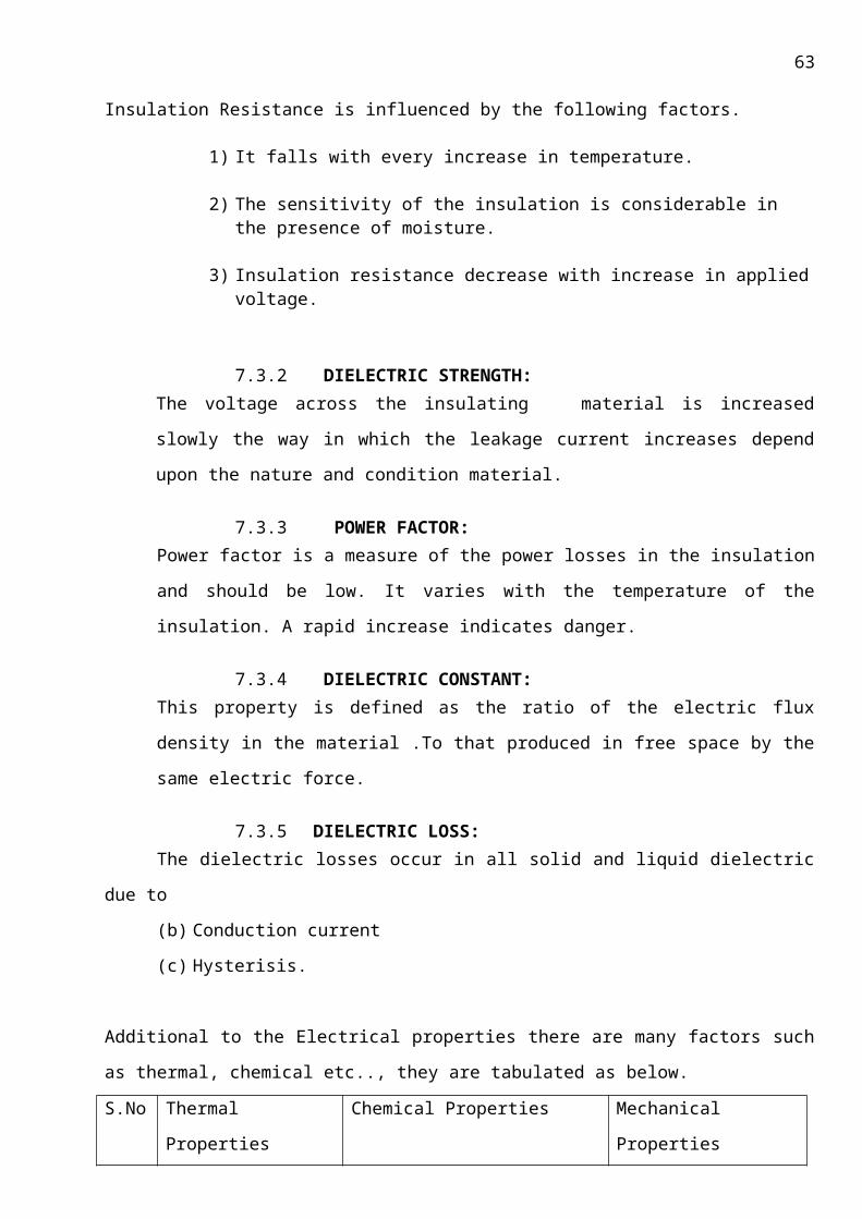
63
is to be pressurised by nitrogen. While admitting resin from storage tanks pressurise to minimum so
that nitrogen will not affect resin to spill over in tank.
Resin settling:
The resin is allowed to settle for about 4mins in such a way that bubble formation ceases
Impregnation Pressurising/gelling
After the resin has settled the job
is subject to pressure cycle of 4 kg/ cm2
of dry nitrogen into the vacuum tank
after obtaining 4 kg/cm2, this is subject
for 2 hrs. in this stage the resin is
impregnated into the micro pores of
the stator and is very firmly embedded
into the crevices of the stator ,so thus
acting as a tough layer of insulation for
the stator ,being indestructible in the long run. Fig: vertical
VPI tanks for smaller jobs
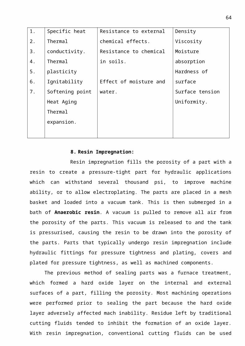
64
Withdrawal of resin from impregnation tank to storage tank
The resin that is pressurised as per pressure cycle is drawn into the tank by the opening of
relevant valves will allow the resin to come back to the storage tank. The job also shall be allowed
for dripping of residue of resin for about 10min. After dripping, withdrawal of resin in various
storage tanks is to be carried out. This is necessary because resin is a very costly material.
Taking out the tub with job from impregnation tank
The lid is then opened after taking precautions of wearing mask and gloves for the operating
personnel as a protection from fumes. The job is withdrawn from impregnation tank by sliding on
railing for horizontal and slinging on to crane for vertical impregnation tanks.
12.3.5 Post curing:
The job is post heated. The time and temperature to which the job has to be scheduled is
varies according to the type of job and is given in the table. The time at which the
heating is started, achieved and maintained is to be logged. The wound stator is subject to 140 +/- 5
deg. After obtaining 140 deg the stator is subject for 32 hrs. The stator is then made to rotate at 1
rpm up to 120 deg. It is then allowed for cooling without opening the doors till the temperature
reaches 80 deg, after attaining the temperature of 80 deg, the doors are opened and wound stator
is sprayed with epoxy red gel on the overhangs and is allowed for drying.
65
Cleaning : entire wound stator is cleaned for resin drips, after which its subjected to HV and tan
delta tests
12.3.6 Electrical testing:
All jobs that are impregnated till above process are to be tested for electrical tests. After
ensuring that all the temperature/vacuum conditions stipulated for drying, impregnation and curing
operations have been properly followed, the job is to be released for this operation.
12.4 Global processing:
Processing details depends very much on the machine type, on customer’s defined parameters and
type of mica tapes.
Generally the VPI system is used in impregnation vessels up to 30T where the rotor/stator is
impregnated at elevated temperatures. Machine parts usually are preheated (also under vacuum) in
order to remove moisture and to reduce viscosity during impregnation.
12.5 Resin management:
After impregnation the VPI bath is pumped into storage tanks and cooled down to 5-10 C
and should be stored in dry conditions in order to obtain a long bath life. Actual bath life depends on
additional parameters, e.g., impregnation temperature and duration of impregnation, impurities in
the bath, wash-out of catalyst from mica
tapes into the un- accelerated resin system
(B), replenishment rate, moisture exposure
etc,. The viscosity of the bath should be
checked periodically in order to maintain a
suitable viscosity for impregnation.
Impregnated, yet uncured machine parts in
unconditioned atmosphere may pickup
moisture. Therefore curing directly after
impregnation or storage in moisture
controlled area is recommended. Generally
machine parts are rotated when removed fig: showing the
resin tank in which resin is stored. from the bath and during the first part of curing in order to avoid
drip off.
Evaporation of hardener during the vacuum cycle leads to a change in the resin/hardener ratio in
the bath and has to be compensated. Therefore replenishment is mixing ratios of 100-120pbw of
66
hardener HY 1102 per 100pbw MY 790-1 are generally used. Replenishment mixing ratios depend
on actual processing parameters and conditions and have to be evaluated at the customer site.
Due to excellent latency of the system (A) MY 790-1/HY 1102/DY 9577/DY073 the replenishment
volume to maintain a constant viscosity is comparatively small, even if impregnation is performed at
40-50C.
On single coils and roebel-bars the mica insulation is normally covered with a tight glass tape to
prevent drainage of the impregnation resin.
12.6 Specific Instructions:
Depending on the insulation materials and the accelerating agent in use, a ramped curing
schedule is recommended.
In systems with high reactivity, where the accelerator can be include in the mica-tape, a fast
gelation can be obtain with a temperature-shock, and draining can so be reduced or avoided.
Standard curing with the standard accelerated mixture (system A) is:
11 at 90C plus 18 h at 140C
12.7 Precaution:
To determine whether cross linking has been carried to completion and the final properties
are optimal, it is necessary to carry out relevant measurements on the actual object or to
measure the glass transition temperature. Different gelling and cure cycles in the
manufacturing process could lead to a different cross linking and glass transition
temperature respectively.
12.8 Features and Benefits:
• State-of-the-art process for completely penetrating air pockets in winding insulation.
• Increases voltage breakdown level. (Even under water!)
• Proven submergence duty system
• Improved heat transfer- windings are cooler, efficiency is improved.
• Improves resistance to moisture and chemicals.
• Increases mechanical resistance to winding surges.
An overview of entire VPI process with the time taken for each process according to the type of the
job used is given below in a tabular form
Vacuum Pressure Impregnation of resin poor insulated jobs:
Variant Description
67
01 Brushless exciter armature, PMG stators and Laminated rotors 02 Stator wound with diamond pulled coils.
03 Stator with half coils
Variant-01 Variant-02 Variant-03Any other
information
Preheating 605C for 3hrs
605C for 12hrs
603C for 12hrs
Vacuum to be maintained 0.4mbar 0.2mbar/0.4mbar
<0.2mbar(both
together shall not exceed
50hrs including
rising time)
Vacuum heating time 3hrs
0.2mbar for 9hrs 0.4mbar for
17hrs
Stopping vacuum
pumps for 10min shall check 17hrs
vacuum drop. The vacuum
drop shall not exceed by
0.06mbar for 10min
Increase in pressure
40min 80min 80min
Maximum pressure
3bar 4bar 4bar
Pressure holding
3hrs 3hrs 3hrs
Post curing At1405C for 14hrs
At1405C for 32hrs
At1405C for 32hrs
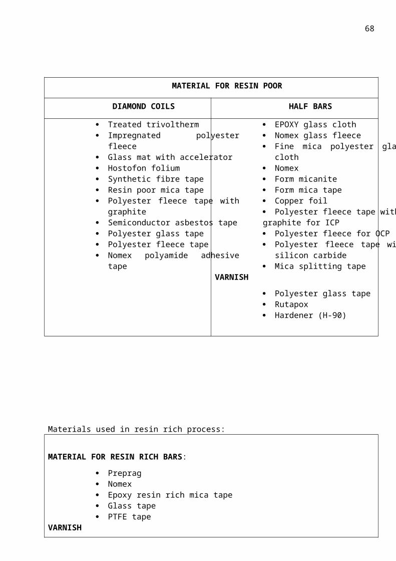
68
13. FACILITIES AVAILABLE IN VPI PLANT IN BHEL:
The major facilities available in VPI plant are:
Steam furnace for preheating
Size of chamber: 2 * 2 * 6.5 M
Maximum temperature: 160C
Electrical power consumption: 75KW
Work place: 1425
Work centre: 3215
Stream inlet: 200-250C
Impregnated tubs for keeping jobs
For vertical impregnation: As per respective tech. Document.
For horizontal impregnation: As per respective tech. Document.
Specifications of plant:
Impregnation medium
(a) Epoxy resin (class F solvent free) and hardener mix in 1:1 ratio as per TG34967
(b) Epoxy resin (class F solvent free) and hardener mix in 1:1 ratio as per TG34931
Horizontal impregnation chamber
Diameter: 4000mm
Cylindrical length: 9000 mm
Operating over pressure: 6 bar
Operating vacuum: 0.15 mbar
Operating temperature: 90C
Loading weight of impregnation object: maximum of 120 tonnes
Maximum leakage rate: less than 1mbar/lit/sec.
Moving load: 140 tonnes.
Static load: 170 tonnes
Pressure medium for impregnation
Pressure medium: dry nitrogen
Operating pressure: 6 bar.
Nitrogen storage capacity: 52cubic meter at 25 bar.
Resin storage capacity
69
Total storage: 5*9000L+1*3000L
Operating parameters of each tank
Operating vacuum: 0.5mbar
Operating over pressure: 0.5bar
Operating temperature: 80C
Resin filters(stainless steel washable)
Filter fineness: 150microns
Output (maximum): 1000lits/min
Vacuum system
Root pumps: 2No.s, 5.5KW each
Suction capacity: 2000cubic meter/hr
Vacuum pumps(4No.s, 7.5KW each)
Suction capacity: 250 cubic meter/hr
This system is provided with separator filter with activated carbon filters, to protect the
vacuum pumps from resin and hardener vapours.
Refrigeration system
The resin inside the tanks has to be stored at 102C. this can be stored for indefinite period
with a brine chilling/refrigeration system.
The brine storage capacity: 1*25000L+1*26000L
Composition of brine: 40%Mono Ethylene glycol and 60%water
Heating and cooling system
The heating of resin in the storage tanks and the impregnation chamber is by circulating the
heated brine through the heat exchangers, to heat by saturated steam. The hot brine is cooled
to about 40C by circulating water through coolers and then the brine is chilled to -10C and
stored in the tanks.
Post heating of job
(a) Explosion proof steam drier and electrical heating superposed.
Size: 7*4.5*4.5M
Maximum weight of job: 80 tonnes
Maximum temperature: 150C
(b) Indirectly heated hot air circulating oven (gas fired)
Size: 9*4.5*4.5M
Maximum weight of job: 170 T/120T with facility for rotation.
Maximum temperature: 150C
70
b.2 DATA COLLECTION OF SAMPLES
During the project two jobs have been impregnated in VPI Plant, the data has been collected and
recorded in the project report.
b.2.8 INDO-BHARAT-II ROTOR
Preheating:
Indo Bharat II rotor is loaded for preheating in steam furnace on 30-5-2003 at 18:00hrs.
Date and timeRTD-I(C) RTD-II(C) Furnace air
temperatureRemarks
30.5.2003 19:00 32.0 30.0 45.6
Rotor temperature is reached to 603C at 2:00hrs on 31.5.2003 and it is maintained for 4 hrs i.e., up to 6:00 on 31.5.2003
30.5.2003 20:00 45.4 48.6 57.930.5.2003 21:00 49.9 50.9 63.430.5.2003 22:00 52.5 54.3 70.530.5.2003 23:00 53.3 55.1 73.4
30.5.2003 24:00 56.6 57.3 75.6
Rotor is switched to vac 140 tank at 7:00 hrs on 31.5.2003
31.5.2003 1:00 59.9 60.2 75.131.5.2003 2:00 62.4 63.9 77.031.5.2003 3:00 62.3 64.7 77.031.5.2003 4:00 63.3 64.1 75.031.5.2003 5:00 63.3 64.0 75.631.5.2003 6:00 63.1 63.7 75.6
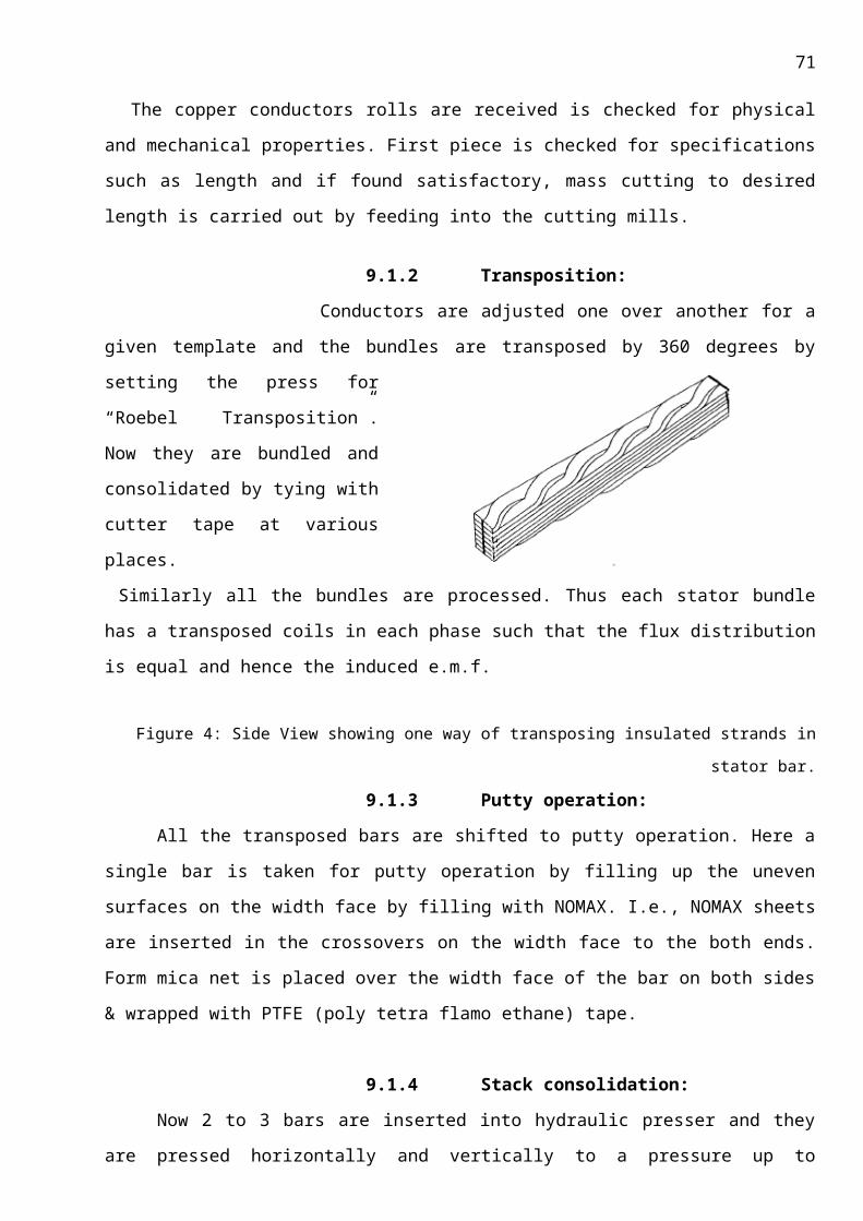
71
12.9
12.10 Date and
time
12.11
12.12R
12.13
12.14R
12.15Room
temperature
12.16(C)
12.17
12.18 Remarks
12.19 31.5.2003 19:30
12.206
12.216
12.2236.0
12.23 Resin tank 025 is heated for impregnation
12.24 31.5.2003 21:30
12.257
12.266
12.2736.7
12.28
12.29 31.5.2003 23:30
12.308
12.318
12.3236.7
12.33 1.6.2003 1:30
12.341
12.359
12.3635.6
12.37 Resin admission started at 14:10 hrs on
72
31.5.2003

73
12.38 1.6.2003 3:30
12.391
12.401
12.4134.8
12.42 Resin admission completed at 14:25 hrs on 31.5.2003
12.43 1.6.2003 5:30
12.441
12.451
12.4633.8
12.47 Pressurisation started at 14:45 hrs on 31.5.2003
12.48 1.6.2003 7:30
12.491
12.501
12.5133.2
12.52 Pressurisation completed at 15:30hrs on 31.5.2003
12.53 1.6.2003 9:30
12.541
12.551
12.5636.5
12.57 Pressurisation hod up completed at 18:30hrs on 31.5.2003
12.58 1.6.2003 11:30
12.591
12.601
12.6138
12.62 Resin withdr
74
awal to storage tanks is from 18:30 to 18:45hrs on 31.5.2003
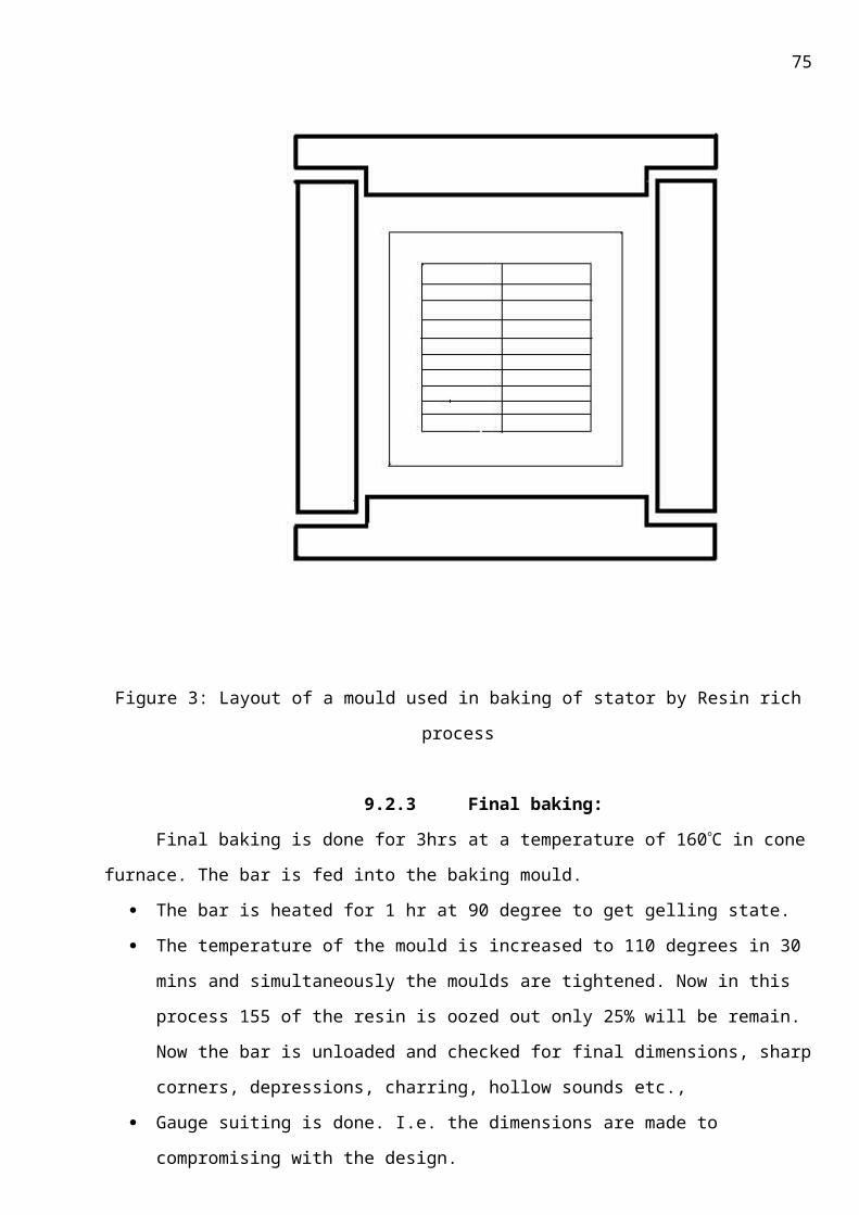
75
12.63 1.6.2003 13:30
12.641
12.651
12.6642.8
12.67 Rotor loaded in gas furnace at 19:15hrs on 31.5.2003
12.68 1.6.2003 15:30
12.691
12.701
12.7143.8
12.72 Rotor temperature is reached to 131.6 to 145.7C at 8:30hrs on 1.6.2003 and it is maintained for 14hrs i.e., up to 22:30hrs on 1.6.2003
12.73 1.6.2003 17:30
12.741
12.751
12.7642.8
12.77
12.78 1.6.2003
12.791
12.801
12.8141.0
12.82 Furnace
76
19:30 is switched at 22:30hrs on 1.6.2003 and circulation fans are kept running till the job temperature is reached to 70C to 75C.
12.83 1.6.2003 21:30
12.841
12.851
12.8640.8
12.87
12.87.5.1.1 Vacuum cycle:
Date and time Vacuum in
graph (mbar)Vacuum in
meter (mbar)
Job temperature
(C)Remarks
31.5.2003 7:00 -- -- 62.2
Vacuum pump started at 7:30 hrs on 31.5.2003.
31.5.2003 8:00 -- 3.0 61.531.5.2003 9:00 0.85 0.86 61.331.5.2003 10:00 0.54 0.55 61.131.5.2003 11:00 0.39 0.4 61.131.5.2003 12:00 0.38 0.4 61.131.5.2003 13:00 0.37 0.4 61.031.5.2003 14:00 0.36 0.39 61.0
RESIN CYCLE AND POST CURING CYCLE:
77
b.2.9 INDO-BHARAT-II STATOR:
Preheating:
Indo-Bharat-II stator is loaded for preheating in steam furnace on 7-5-2003 at 23:30hrs.
Date and Time RTD-I(C) RTD-II(C) Furnace air
temperature(C)12.87.5.1.1.1.1.1.1
7.5.2003 23:30 36.3 36.1 Stator temperature
is reached to 60.5C
to 62.9C(603C) at
7:30hrs on 8.5.2003
and it is maintained
for 12hrs i.e., up to
19:30hrs on
8.5.2003
8.5.2003 1:30 43.6 42.9
8.5.2003 3:30 52.0 51.74
8.5.2003 5:30 55.9 56.0
8.5.2003 7:30 60.5 62.9 Stator is loaded in
vac(140) tank at
21:00hrs on
8.5.2003
8.5.2003 9:30 61.3 62.9
8.5.2003 11:30 60.3 62.4
8.5.2003 13:30 60.3 62.6 Vac. Pump is started
at 2:30hrs on
9.5.2003
8.5.2003 15:30 62.5 62.9
8.5.2003 17:30 62.9 62.66
8.5.2003 19:30 62.4 62.1
78
Vacuum cycle:
12.87.5.1.1.1.1.2Vacuum in
graph (mbar)
Vacuum in
meter (mbar)
Job
temperature
(C)
8.5.2003 22:00 -- -- 54.37 Resin tanks 025,102 are
heated for impregnation
8.5.2003 0:00 -- -- 54.89 Viscosity of resin at 60C
is 33CP
9.5.2003 2:00 -- -- 59.02 Viscosity after aging is
36.10CP
9.5.2003 3:30 0.65 0.65 61.6 9.5.2003 and 10.5.2003
9.5.2003 5:30 0.41 0.40 63.59 Resin admission started at
19:45hrs
9.5.2003 7:30 0.28 0.29 64.2 Resin admission
completed at 19:55hrs
9.5.2003 9:30 0.22 0.22 63.2 Pressurisation started at
20:00hrs
9.5.2003 11:30 0.19 0.19 62.3 Pressurisation of
4kg/sq.cm reached at
21:20hrs
9.5.2003 13:30 0.18 0.18 62.1 Pressurisation hold up for
3hrs is at 0:20hrs
9.5.2003 15:30 0.17 0.17 62.0 Resin withdrawn to
storage tanks is from
0:30hrs –1:00hrs
9.5.2003 17:30 0.14 0.14 61.8 Stator loaded in hot air
furnace from 1:00hrs –
1:30hrs on 10.5.2003
9.5.2003 19:30 0.14 0.14 61.3
79
Post curing:
Date and
Time
ESOH
15T
TSOH
06B
ESW
02
TSW
13Core
Room
temperatureRemarks
10.5.2003
1:30hrs70.0 76.4 62.4 62.5 63.4 33.1
10.5.2003
4:30hrs126.7 131.4 94.7 102.3 98.8 31.7
10.5.2003
7:30hrs144.3 154.1 125.4 134.5 126.1 31.6
10.5.2003
10:30hrs147.7 154.9 139.9 145.1 140.6 34.8
10.5.2003
13:30hrs137.6 144.4 139.3 141.6 140.7 38.0
10.5.2003
16:30hrs136.9 144.2 140.0 140.9 140.6 38.4
10.5.2003
19:30hrs140.2 143.6 140.1 140.7 140.2 37.2
10.5.2003
22:30hrs144.4 151.3 143.7 145.1 144.1 35.9
Job temp. is reached to
1405C i.e., from
136.2C to 145.6C at
9:30hrs on 10.5.2003 and
it is maintained for 32hrs
i.e. up to 17:30hrs on
11.5.2003.
11.5.2003
1:30hrs143.1 146.7 145.2 145.1 145.2 33.8
11.5.2003
4:30hrs144.3 151.0 143.6 144.0 144.7 31.1
11.5.2003
7:30hrs135.7 142.1 144.3 145.1 145.0 31.3
11.5.2003
10:30hrs135.0 135.7 135.1 135.0 135.8 34.8
11.5.2003
13:30hrs135.6 141.4 135.4 135.6 135.9 38.3
80
11.5.2003
17:30hrs148.0 149.2 142.8 142.2 142.1 39.8
Furnace is switched
off at 17:30hrs on
11.5.2003 and
circulation fans kept
running till the job
temperature is
reached from 70C-
75C
12.87.5.1.2
b.2.10 High voltage levels of stator/rotor windings for multi turn machines:
S.No. Description HV level HV in kv remarks
Stator winding
1. After laying and wedging of
coils
18.9/1’ RTD,IT test
2. After OH spacers and
forming eyes
18.03/3’ RTD,IT test
3. Before impregnation
17.5/1’ R, RTD test
4. After impregnation
26.0/1’ R, RTD, Tan, leakage
reactance test5. Customer
acceptance25.0/1’ Rotor winding
Rotor winding
1. After laying first coil
UT+1400 2.9 Pole drops
2. After laying second coil
UT+1250 2.75 Pole drops
3. After laying third coil
UT+1100 2.6 Pole drops
4. After laying fourth coil
UT+950 2.45 Pole drops
5. After laying fifth coil
UT+800 2.3 Pole drops
6. After laying sixth coil
UT+650 -- Pole drops
7. After all -- -- R, Pole drops

81
connections8. After tech.
rings assembly-- 2.15
9. After bandage -- 2.0 R, Pole drops10. After
impregnation-- 1.9 R, Pole drops
11. After excitation cable assembly
-- 1.8 R, Pole drops
12. After balancing UT+200 1.7 R,Z with 50Hz
b.2.11 TESTING RESULTS OF INDO-BHARAT-II ROTOR
Customer name: INDO-BHARAT-II ROTOR
M/c rating: 10.8MW, 12kv, 1500rpm.Test: Z, R and H.V test.
Stage: after impregnation.
Ambient temperature: 35C
Ohmic resistance: 0.264 (rotor temperature was more)
Voltage( volts) Current(amps)215.0 0.5
367.5 1.0523.0 1.5
High voltage test: IR value before H.V. test at 15”/60” -- 200/300 M H.V. applied at 1.9kv /1’ – withstood IR value after H.V. test at 15”/60” -- 200/300 M
b.2.12 TESTING RESULTS OF INDO-BHARAT-II STATOR:
Customer name: INDO-BHARAT-II STATOR
82
M/c rating: 10.0MW, 12kv, 0.8pf, 650A, 1500rpm.
Test: H.V test.
Stage: after impregnation.
Ambient temperature: 36C
A PHASE: IR value at 2.5kv IR value before H.V. test -- 1000/2000 M H.V. applied at 26-25kv /1’ – withstood IR value after H.V. test -- 1000/2000M
B PHASE: IR value at 2.5kv IR value before H.V. test -- 1000/2000 M H.V. applied at 26-25kv /1’ – withstood IR value after H.V. test -- 1000/2000M
C PHASE: IR value at 2.5kv IR value before H.V. test -- 1000/2000 M H.V. applied at 26-25kv /1’ – withstood IR value after H.V. test -- 1000/2000M
34.5 INDO-BHARAT-II STATOR:
Customer name: INDO-BHARAT-II STATOR
M/c rating: 10.0MW, 12kv, 0.8pf, 650A, 1500rpm.
Test: H.V test-RTD measurement, resistance measurement.
Stage: After impregnation.
Ambient temperature: 36C
Excitation Side:
26 113.8 10 114.062 113.8
83
50 113.820 113.838 113.914 113.8
Turbine Side:
49 125.013 113.825 113.921 113.861 113.837 113.91 113.8
A-A --29.4mB-B -- 29.3mC-C -- 29.4m
c. COMPARISION BETWEEN RESIN POOR AND RESIN RICH SYSTEMS:
RESIN POOR SYSTEM RESIN RICH SYSTEM
84
1. The insulation tape used in this system
has 40% resin.
2. This method follows thermosetting
process.
3. There is a need for addition of resin from
outside.
4. Reduction in time cycle for this process
5. No tests are carried out while at
processing
6. Processing of bars along with stator and
with conductors and processing of exciter
Coils along with exciter is possible.
7. The cost of repair is more
8. The overall cost is less
compared to resin rich system.
1. The insulation tape used in this is 7% of
40% resin.
2. Same as in resin poor.
3. Further addition of resin is not required
from outside.
4. It is very long process and time
consuming while at processing stage.
5. Tests are being carried out Stage.
6. Processing of stator bars is
only possible in resin rich
systems.
7. Repairing work is easy.
8. The total cost in this process is more.
Applications:• All critical machines
• Equipment exposed to frequent surges/starting
• Harsh or moist environments
• Motors that run at service factor
c.2 DRAWBACKS OF VPI SYSTEM:
Number of RTD’s required are more
The whole operation is time consuming
It depends largely on moisture and season of operation
Maintenance of resin below room temperature about 8-12C is complicated.
c.3 SUGGESTIONS:
85
Processed in a Clean Room Environment To ensure optimum rewind integrity, all rewinds should be conducted in a clean,
temperature- and humidity-controlled environment. It ensures optimum material performance and
prevents dirt or moisture contamination during the process.
VPI Process Control Throughout the VPI process, each stator is continuously monitored by computer to ensure
homogenous fill.
How can we say that the present VPI BY RESIN POOR process currently used in BHEL is a superior
process as compared to VPI by resin rich process ? inorder to find an answer to this question the
justification follows:
c.4 JUSTIFICATION
We can say that VPI by resin poor system is more superior to other types of insulation by conducting
h v and tan delta tests, and the results of which are clearly indicated in the graphs below:
3. High Voltage test:
Equipment
*50 Hz A.C High voltage transformers and its induction regulator/input
autotransformer.
* Potential transformer (35 or100KV/100V)
* Voltmeter
*Binding wire
* Earthing Rod and Earthing wire/cable
When H.V test is done on one-phase winding, all other phase windings, rotor
winding, instrumentation cables and stator body are earthed.
The high voltage is applied to winding by increasing gradually to required value and
maintance for 1 minute & reduced gradually to minutes. The transformer is switched
off & winding discharged to earth by shorting the terminal to earth using earthing rod
connected to earth wire/cable.
The test is conducted on all the phases & rotor winding separately.
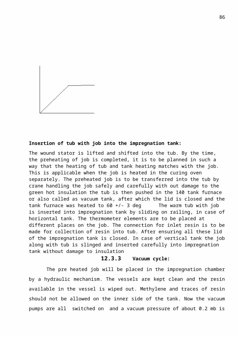
86
HV Test Levels:
Stator winding: (2Ut+1) KV =23 for 11 KV machine
Rotor winding: (10 Up) volts (with min of 1500v & max of 3500v),
Where, Ut= Rated of machine under test Up= Excitation voltage.

87
TAN TEST:
Equipment: Schering Bridge
This test is conducted to check the presence of impurities in the insulation
& tan value for each phase & also for combined phases is noted down.
Tan value should be generally less than or equal to 2%.
TESTING RESULTS:
Vph (0.2Un ) Rated KV= 10.5KV , 3000RPM.
Uph Tan
2.1 0.815
4.2 0.832
6.3 0.869
8.4 0.903
10.5 0.938
Wph Tan
2.1 0.806
4.2 0.820
6.3 0.857
8.4 0.899
10.5 0.941
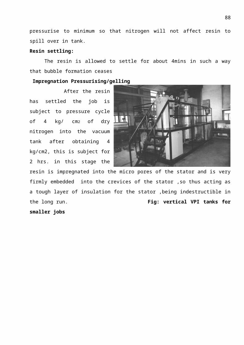
88
Vph Tan
2.1 0.811
4.2 0.830
6.3 0.868
8.4 0.905
Uph Vph Wph Tan
2.1 1.18
4.2 1.209
6.3 1.230
8.4 1.254
10.5 1.268
Rating: 31.25, 250 MW, 11KV, 1640A, 0.8pf, 3000rpm.
SCC:
Ia Ib %In If Vd Id Dm
O/P
0 0 0 0.01 559.0 404.58 226.16
337.2 337.6 20.57 94.7 515.95 443.1 228.60
664.8 666.2 40.5 187.1 516.04 481.4 248.44
1005.
8
1006.1 61.34 281.51 516.52 533.6 275.6
1324.
9
1326.5 80.84 369.16 516.54 651.25 336.35
1495.
2
1496.9 91.2 415.2 516.18 690.3 356.32
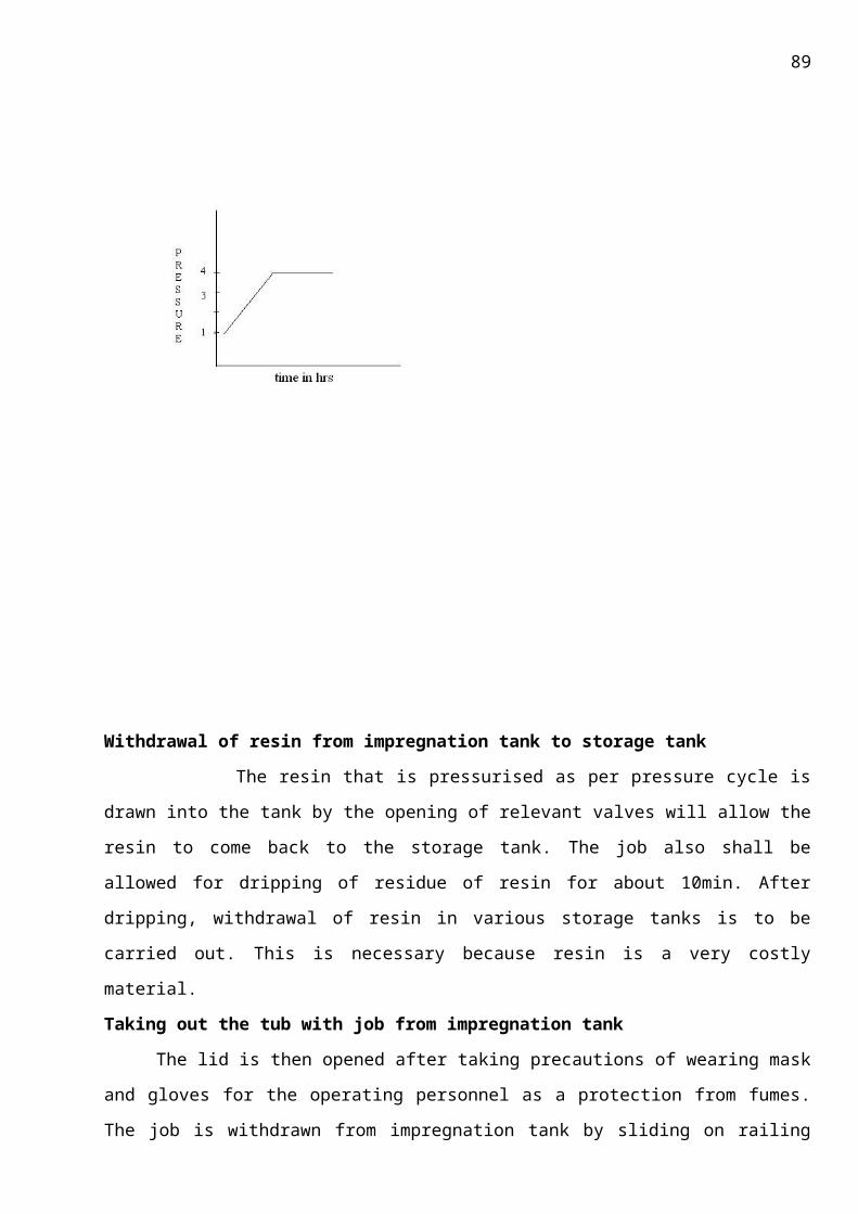
89
OCC:
Vab Vbc Vca %En If Vd Id Dm
O/P
35.3 35.3 35.3 35.32 0.01 512.4 419.85 215.16
2281.2 2282.5 2281.8 20.74 40.44 512.93 423.15 216.62
4447.4
2
4441.4 4448.2 40.44 77.05 512.4 442.45 226.71
6662.0 6665.0 6663.0 66.58 116.65 512.3 466.43 288.95
8845.0 8849.0 8846.0 80.4 160.3 512.19 501.08 256.64
10015.
0
10019.
0
10017.
0
91.06 186.56 512.25 517.25 264.93
Graphs

90
Resistance Measurement:
Instrument: Micro ohm meter
Resistance at 25c (m) Resistance at 20c (m)
Rotor 264 258.92
R75 = (( 235+75)/(235+20)) x R20= (310/255) x (0.2587)=0.3147
Rotor current = 562 A
Efficiency = (output)/(output+losses)
Losses = 99.532 + 9.9532 + 39.39 + 385.15 + 286. 38 = 820.40
Efficiency= (25000/25000 + 820 .40 ) = 96.82%
d. PRESENT INSULATION SYSTEMS IN THE WORLD
Four major manufacturing processes have been and are still widely used to form and
consolidate insulation systems for form-wound stators. They are:
1. Vacuum pressure impregnation (VPI) of individual coils and bars
2. Global VPI of complete stators
3. Hydraulic molding of individual coils and bars using resin-rich tapes
4. Press curing of individual coils and bars, also using resin-rich tapes
There are some combinations of these methods also in use. The binder resins can be
categorized as high- or low-solvent-containing and solvent less, as well as by their chemical nature.
Although no longer manufactured for coils in new stators, there are many machines still in service,
and expected to remain in use for several more decades, that are insulated with asphaltic mica
splitting.
There are four principal drivers that govern the selection of the insulation systems currently being
manufactured. They are:
1. Good service experience with earlier versions of the same basic system
2. Commercial availability of the materials to be used
3. Relative costs of the raw materials and processes in the competitive machine-sales environment
4. Design advantages or limitations each insulation system and process brings to the final generator
or motor for its expected service life and economy of operation

91
New insulating materials may require the development of new or significantly modified
manufacturing processes to obtain the insulation system improvements inherent in the materials.
By the 1990s, the major insulation suppliers were offering full insulation systems, including the basic
processing know-how, to their customers. For smaller OEMs and most repair shops, the insulation
supplier’s materials, other acceptable materials, and processing specifications are all that is needed
to support work. The final insulation system may use the materials supplier’s trade name, e.g.,
VonRoll ISOLA’s Samicatherm™ and Samicabond™.
Larger OEMs still work with insulation suppliers to optimize both the materials and processes for
new or changed insulation systems.
The first consideration in using modern insulation systems is the method of applying the
ground-wall materials to form-wound stator coils and bars. As discussed in Section 3.10,
the Haefley process was widely
used decades ago to apply wide
sheets of insulation material to
coils.
Presently, however,
virtually all ground-walls are
fabricated by the application of
relatively narrow (2–3 cm wide)
tapes. When tapes were first
introduced, and for many
decades thereafter, they were
applied with hand by skilled
tradesmen. There are many
companies into insulation manufacture, mainly all the companies have these insulation systems as a
trade secrets. So one cannot point out which is the best insulation system as there are many factors
such as availability in a particular country, so insulation systems are given different names ,though
the composition just differs a wee bit, so let us have a brief overview
d.2 Westinghouse Electric Co.: Thermalastic™
Westinghouse Thermalastic™, the first modern synthetic insulation system. The first
Thermalastic insulated generator went into service in 1950, in the 1960’s minor changes that were
Fig: A modern stator bar taping machine that applies tape both
in the slot and end winding portions of the bar.
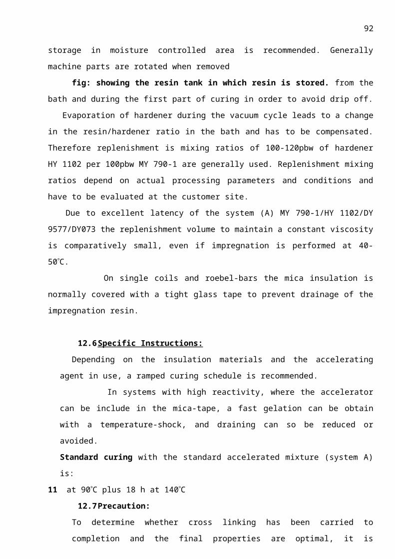
92
made included introduction of glass cloth as a backing material for the mica, resin modifications to
help VPI resin tank stability, and improvements in the partial discharge suppression treatments on
generator coil surfaces. Although large turbine generators continue to use the individual bar
impregnation and cure method, motors and smaller generators shifted to the global VPI method in
the early 1970s [4.4]. The hybrid epoxy VPI resin used for turbine generators was optimized for
the previously developed processing equipment and insulation requirements. It is comprised of a
modified epoxy resin, prepared in a resin cooker to create polyester linkages, and is compatible with
styrene for viscosity control. The final resin cure was achieved by cross-linking through the epoxy or
oxirane group.
After Siemens acquired Westinghouse in the late 1990s, the Thermalastic system underwent
many refinements in materials and processing while maintaining the same resin system. Now a days
there are not much changes though.
d.3 General Electric Co. :Micapals I and II™, Epoxy Mica Mat™, Micapal HT™, and hydromat™
It was introduced to the industry in an IEEE Technical paper [4.5] in 1958, after several years
of limited production. Micapal 1 contained approximately 50% GE Micamat™ (paper), made with
calcined muscovite, and 50% muscovite splitting.
winding operation.
After a 12-year development program, General Electric announced the MICAPAL II™ insulation for
large turbine generator stator windings in 1978 [4.8]. This solvent less, resin-rich, second-generation
epoxy mica paper insulation system has been used on most large steam turbine generators since
that time.
In 1999, GE began to offer a reduced-build strand-and-turn insulation, using similar metal
oxide fillers in the large-motor business. These machines use the global epoxy VPI process to make
the glass-fabric-supported Mica-mat insulation systems for machines at least up to 13.8 kV ratings.
Several generations of VPI resins have been used by GE for motor manufacture. Two of these epoxy
resin systems have been based on controlled reactivity chemistry. The most recent improvement
creates polyether linkages in cured di-glycidyl ether bis-phenol, an epoxy resin provides high
reactivity at curing temperatures with excellent shelf life at room temperature.
d.4 Alsthom, GEC Alsthom, Alstom Power: Isotenax™, Resitherm™, Resiflex™, Resivac™, and
Duritenax™
93
During the 1950s, Alsthom licensed the resin technology used in the GE Micapal I system to create
the first Isotenax™ system. There were several differences in materials and processes between the
two systems. Isotenex used only mica paper, not mica splittings. The resin-rich impregnating epoxy
contained significant amounts of a solvent mixture that had to be removed after the glass-backed
mica paper tape was wrapped around the stator bars. Since the 1980s the UK operations of Alsthom
have also worked with global VPI processing and an insulation system called Resivac™. Recent
advances in the VPI system have used bisphenol epoxy resins with a latent Lewis acid catalyst
system
d.5 Siemens AG, KWU: Micalastic™
Siemens began using the individual-bar VPI process with polyester resins and mica splittings as early
as 1957 for hydro and steam turbine generators, with initial help from Westinghouse. This system
was trade named Micalastic. Production continued with this combination of resins and processes for
at least 10 years. Except for indirect cooled generators and direct-cooled generators rated at more
than about 300 MVA or so, which still use the individual bar epoxy VPI methods, the global VPI
process has been standard for all motor and turbo generator stators since 1986 [4.18]. For its
large global VPI stators, this manufacturer avoids difficulties due to shear stress at the interface of
the bar to the stator core (Section 8.2) by employing a slip plane. The slip plane consists of mica
splitting sandwiched between two semi conductive tapes.
d.6 ABB Industrie AG: Micadur™, Micadur Compact™, Micapact™ and Micarex™
Brown Boveri AG started changing from resin-rich asphalt mica flake ground-wall insulation about
1953, first using modified polyester resins and then switching to epoxy resins to make resin-rich
tapes. The ABB Group name for bars and coils manufactured from the epoxy resin-rich system is
Micarex™. Initially, these tapes were applied by hand and later by machine taping, followed by hot-
press consolidation and curing. New machine production with this system will stop with the end of
turbo generator production in Sweden, although some repair licensees will continue using Micarex
for some time.
The Micadur™ insulation system was introduced in 1955 by Brown Boveri as an individual bar
VPI method before the merger of ASEA with Brown Boveri to form ABB in the mid 1980s, ASEA also
developed the technology for individual bar VPI production, using similar materials. The result was
Micapact™, introduced in 1962 for the stator insulation of large rotating machines. It was made with
glass-backed mica paper, impregnated with a special mixture of an epoxy resin, curing agent, and
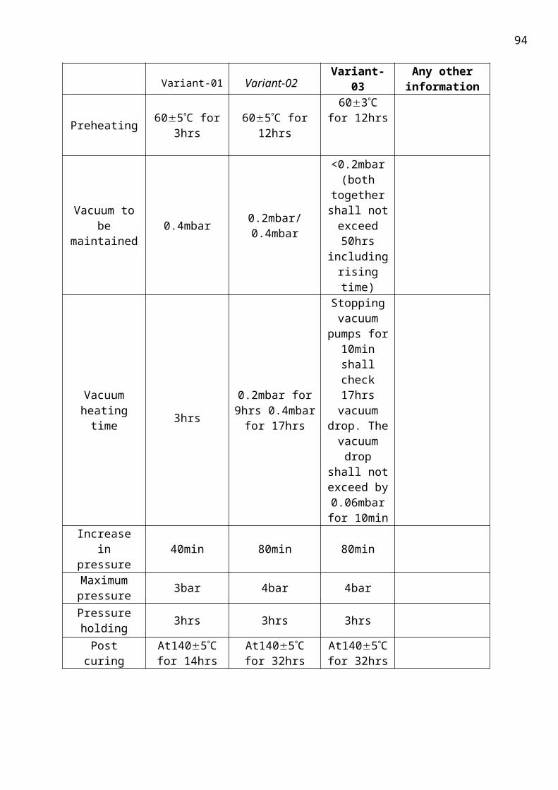
94
additives. Unlike most other VPI tapes, the glass backing and mica paper lack any impregnant or
bonding resin. The adhesion between mica paper and glass was accomplished by an extremely thin
layer of material, which was melted at a high temperature during formation of the tape. The tape
did not contain any volatile matter, which means that the completed machine taped bar insulation
was more easily evacuated and impregnated.
d.7 Toshiba Corporation: Tosrich™ and Tostight- I™
The Toshiba Tosrich™ insulation system for low-voltage, small-capacity generators with a relatively
small number of insulation layers was based on a resin-rich mica paper tape. The solvent containing
synthetic resin was impregnated into the mica tape, wound onto a coil and cured in a mold.
Although used successfully for many years for smaller machines, its replacement with a solvent less
epoxy, resin-rich mica paper tape during the 1990s allowed the improved Tosrich to be applied to
medium-capacity generators; it is still gaining manufacturing and service experience.
For larger machines, the Tostight-I™ insulation system was developed.A new generation of the
Tostight-I VPI insulation system was introduced in 1998. It has been optimized to improve heat
resistance and to be environmentally friendly in materials, equipment, production methods, and
disposal of waste. The mica paper has been changed to replace the aramid fibrids with short glass
fibers. The new impregnating resin is principally a high-purity, heat-resistant epoxy resin, employing
a complex molecular capsule, latent hardening catalyst that is activated by heat to quickly cure and
produce a high-heat-resistant, mechanically and electrically strong filling material for the mica. The
revised system is manufactured using new production equipment, including a fully automatic taping
machine and a new vacuum pressure impregnation facility and curing oven. The VPI tank is
equipped to control vacuum and impregnation as a parameter of the coil capacitance. The new
Tostight-I is intended to be usable for all types of medium and large generators.
d.8 Mitsubishi Electric Corporation
The ground-wall insulation systems employed by Mitsubishi until the 1990s were largely
based on licenses obtained from Westinghouse. During the late 1990s, Mitsubishi introduced a new
global VPI insulation system for air-cooled generators up to 250 MVA. The new system
supplemented an older global VPI system, used for air-cooled generators of up to 50 MVA rating.
The new system uses a glass-fabric-backed mica paper tape, bonded with a very small amount of
hardener-free epoxy resin as an adhesive. The global VPI resin is an epoxy anhydride.
d.9 Hitachi, Ltd.: Hi-Resin™, Hi-Mold™, and Super Hi-Resin™
95
Hitachi also introduced a pre impregnated or resin-rich mica paper insulation, called the Hi-
Mold™ coil in 1971 This press-cured system uses an epoxy resin to impregnate glass-cloth-backed
mica paper, which is partially cured to the B stage. The high-performance resin was selected to
obtain superior electric and thermal characteristics for use in machines rated for up to Class F
insulation performance. The Hi-Mold system is used for hydro and gas turbine peaking generators
and for heavy duty or other unfavorable environments in synchronous and induction motors.
d.10 Summary of Present-Day Insulation Systems:
A review of subsections 4.2.1 through 4.2.8 shows that all of the world’s larger OEMs are
currently using various mixtures and types of epoxy resins and mica paper to make their stator coil
ground-wall insulation systems. The compositions are adjusted or tailored to accommodate the
exact process used in their manufacture. The end results are comparable in terms of inherent
insulation quality as related to the machine and insulation design parameters, provided that
consistent quality control practices are routinely carried out. This fact is recognized by some large
suppliers of rotating machines, who will, in times of extraordinary demand, out-source or purchase
generators to their own design from competitors, while allowing the supplier to use their own
insulation systems. We presented here the most efficient and reliable system of insulation, the
micalastic insulation
e. A NEW FLUSH IN INSULATION SYSTEM
e.2 MICALASTIC
Of all these insulation processes the insulation which was preferred by ITAIPU power plant was the
MICALASTIC the features of which will be briefed below:
96
As central components of hydroelectric power plants, generators are subjected to operating
stresses which influence the long-term performance of the winding insulation. Failure of the
insulation can lead
to lengthy
downtimes. The un
surpassed
reliability of
products such as
MICALASTIC®
insulation is
therefore of great
economic
significance
The capacity of a
hydroelectric power
plant is determined
by the available
water flow and
head. Both of these
parameters vary widely, and generators can be dimensioned for any rating between 10 kW and 800
MW. The head determines the turbine type as well as the speed, which can lie between 50 and 1500
rpm. Additional parameters include the generator voltage, the rotor’ s moment of inertia, the
runaway speed of the turbine, the physical design of the generator (horizontal or vertical) and
various requirements imposed by the grid. Hydroelectric generators are therefore always custom
designed. Dimensions and weights can assume enormous proportions External diameters of up to
nearly 23 meters are possible, and total weight can amount to as much as 3500 metric tons.
Generators of this size cannot be assembled and tested at the factory. Nevertheless, the generators
can be expected to operate well right after their initial installation at the power plant. It was once
correctly stated that” the construction of a hydroelectric generator can be compared to making a
tailor made suit without trying it on”.
To date, Siemens has manufactured more than 1200 large hydroelectric generators with a combined
capacity in excess of 80,000 MVA. Of these, 360 generators (over 50,000 MVA) have MICALASTIC

97
windings. These machines are characterized by their outstanding reliability, which can be attributed
in large measure to their high quality MICALASTIC insulation system.
e.3 The MICALASTIC Insulation in itaipu
MICALASTIC is the registered trademark for Siemens insulation systems for high-voltage windings of
rotating electrical machines. These systems use mica, a material capable of withstanding high
electrical and thermal loads, together with curable, elastic epoxy resins as bonding material. Since
the early days of electrical machine construction, the naturally occurring, inorganic mineral mica has
been an indispensable constituent of high voltage insulation systems. The most important criterion
for the use of mica is its ability to durably withstand the partial electrical discharges which can occur
inside the insulation due to high electrical stresses.
Manufacturing and Design
As early as 1957, Siemens-Dynamo werk in Berlin manufactured the first stator windings that made
use of mica tape and a vacuum-pressure impregnation process. With this method, single coils and
Roebel bars for hydroelectric generators are continuously wrapped with mica tape in the slot and
end sections. The taped winding elements are then dried out and degassed in a vacuum
impregnation tank, and flooded with low-viscosity, curable synthetic resin. High nitrogen pressure
applied to the impregnating bath completely impregnates the mica tape. After being placed in
accurately sized, portable pressing molds, the insulation is cured at high temperatures in large
chamber ovens. Continued development of this insulation technology ultimately led to the use of a
film of ground mica on mechanically strong glass fabric as the carrier material with epoxy resin as
the impregnant, which produced a very durable electrically, thermally and mechanically),modern
insulation system. Long duration tests in a slot model were unnecessary, since the desired voltage
endurance had already been achieved in the previous development stages (Fig. 2) using lower-
quality carrier materials. Short-duration tests were performed, however, for verification.
Fitting of Roebel Bars into Slots:
Winding elements with cured MICALASTIC insulation are secured in the slots by filling up the
tolerances between the slot wall and the conductive surface (coil side corona shielding) of the bar
insulation. Initially, Siemens used graphite-treated paper as filler material. Since about 1969,
however a special bar fitting procedure has been used for hydroelectric generators. The main
features of this procedure are U-shaped slot liners made of polyester fleece impregnated with a
conductive material, and a conductive, curable synthetic resin paste between the surface of the bar

98
insulation and the slot liner (Fig. 3). Therefore, the insulation does not stick to the stator core, and
the option of removing the bars, even though seldom required, is retained. In the radial direction,
the slot portion of the winding elements is secured by means of various packing strips or ripple
springs, and slot wedges. Bracing the end windings and jumpers by using glass fiber reinforced
spacers and epoxy-resin impregnated cording makes the winding resistant to electro dynamic forces
during operation and to possible short-circuit faults. This resistance is also aided considerably by the
mechanical stiffness of the MICALASTIC insulation, which is also cured within the end winding.
Thermal Stability
The MICALASTIC insulation system was developed strictly for a continuous load in accordance
with temperature class F (155°C). Nevertheless, generator design engineers generally guarantee
compliance with class B (130°C) temperature limits for nominal operating conditions, as is also
required in most invitations to tender. In practice, the stator windings of hydroelectric generators
are frequently dimensioned for even lower operating temperatures, because the stators will usually
be optimized for good efficiency by adding electrically active material (winding copper and core
lamination). Particularly low operating temperatures can be expected in the case of stator windings
with direct water cooling. With an appropriately dimensioned de mineralized-water cooling
system, the maximum winding temperature can be reduced to 70°C and lower. Thermal aging of
the insulation is therefore essentially eliminated, and thermo mechanical stresses are also
substantially reduced. The resulting increase in operational reliability makes a real difference in the
case of hydroelectric generators which are essential to safe grid operation
f. CONCLUSION:
Hence Vacuum-Pressure Impregnation technology can be used in a wide range of applications from
insulating electrical coil windings to sealing porous metal castings. It normally produces better work
in less time and at a lower cost than other available procedures.
Our VPI systems can be configured in a variety of ways, depending on the size and form of the
product to be impregnated, the type of impregnant used and other production factors. System
packages include all necessary valves, gauges, instruments and piping. These systems can be large or
small, simple or highly sophisticated and equipped with manual, semi-automatic or automatic
controls.
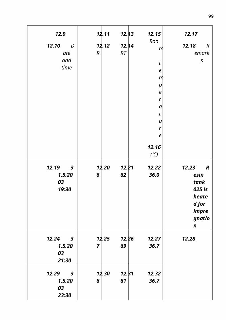
99
Vacuum Pressure Impregnation (VPI) yields superior results with better insulating
properties, combined with “flexible” rigidity, resulting in greater overall reliability and longer life.
VPI reduces coil vibration by serving as an adhesive between coil wires, coil insulation, and by
bonding coils to their slots.
g. Bibliography
Related Documents
![Book - Titanic - Book[1]](https://static.cupdf.com/doc/110x72/5695d3b31a28ab9b029edc2d/book-titanic-book1-56af88a59d4ce.jpg)