1 INTRODUCTION It is well known that adding fibres to a matrix will lead to smaller crack widths and increase the tension stiffening (Noghabai 1998) and also reducing the distance between cracks (Bischoff 2003). However, there is still a need for better knowledge of the cracking behaviour regarding the small crack widths related to the serviceability state of a structure. Crack control, one of the main benefits from using fibre reinforcement, depends to a large extent on the bond mechanism of the reinforcement bar-matrix system. The pull-out behaviour depends on the char- acteristics of the reinforcement bar (geometry and steel type), the surrounding matrix (packing grade, and fibre type and amount), and the level of lateral confinement (cover thickness, amount of transverse reinforcement, possible support pressure etc.). Fibre reinforcement will suppress the opening of splitting cracks and thus provide extra confinement. Researchers agree that fibre reinforcement improves bond strength in case of splitting failure. Regarding the effect at pull-out failure and the bond stiffness (pre-peak behaviour) contradictory results have been reported, as concluded in the state-of-the-art report by Bigaj van Vliet (2001). Different fibre materials and geometry yield dif- ferent pull-out behaviour. E.g. in Chao et al. (2009), it is seen that the addition of 1% by volume of the synthetic fibre UHM-PE 38 mm (polyethylene) yielded markedly higher peak stress and residual stress, compared with a matrix reinforced by 1% regular hooked-end steel fibres, 30 mm long. With a diameter of only 0.038 mm, for random 3D distribution, the average number of the synthetic fibres was 400/cm 2 compared to 2/cm 2 for the steel fibre with diameter 0.55 mm. The larger number of the PE-fibres can effectively maintain the early con- finement. For larger deformations the steel fibre, with its higher Young’s modulus, became more ef- fective. Self-compacting concrete (SCC) has been found to improve bond properties of single fibres. Grüne- wald (2004) reported an increased fibre pull-out force of 15 to 50% for SCC in strength class C45/55. Also the bond between concrete and rebar may gain from the use of SCC. Banthia et al. (1993) found that SCC improved the magnitude of the bond stress in their pull-out tests. They compared plain non- fibrous vibrated concrete with plain non-fibrous SCC, and with fibre-reinforced SCC (SCFRC). In their tests, the peak bond strength was increased by the use of SCC compared with plain vibrated con- crete, but there was no additional improvement by adding fibres (RC 65/35BN 30kg/m 3 ) to the SCC. The aim with the present study was to obtain relevant bond properties for self-compacting steel fibre-reinforced concrete (SCSFRC) to steel bars. Due to the contradictory findings in the literature, it was decided to carry out pull-out tests on specimens with short embedment length. The results from the pull-out tests were used to calibrate a bond model developed by Lundgren (2007). This model de- scribes both the tangential and the radial deforma- tion between the rebar and the concrete. Hence, also Bond between Reinforcement and Self-Compacting Steel-Fibre-Reinforced Concrete A. Jansson AB Färdig Betong, Göteborg, Sweden I. Löfgren Thomas Concrete Group AB, Göteborg, Sweden K. Lundgren & K. Gylltoft Chalmers University of Technology, Göteborg, Sweden ABSTRACT: In this study, pull-out tests of specimens with short embedment length and varying fibre content were carried out. The results showed no effect from the fibres on the bond-slip behaviour before peak load when normalized with respect to the compressive strength. After peak, the fibre reinforcement provided extra confinement, changing the failure mode from splitting to pull-out failure. The test results were used to cali- brate a frictional bond model in non-linear finite-element analyses. The model proved to yield results in good agreement with the experimental results regarding failure modes, load-slip relation and splitting strains on the surfaces of the pull-out specimens. The tests and analyses in combination confirmed that the fibre reinforce- ment neither disturbed nor improved the bond properties at the interface layer between reinforcement steel and concrete; i.e. the fibres only provided confinement to the surrounding structure.

Welcome message from author
This document is posted to help you gain knowledge. Please leave a comment to let me know what you think about it! Share it to your friends and learn new things together.
Transcript

1 INTRODUCTION It is well known that adding fibres to a matrix will lead to smaller crack widths and increase the tension stiffening (Noghabai 1998) and also reducing the distance between cracks (Bischoff 2003). However, there is still a need for better knowledge of the cracking behaviour regarding the small crack widths related to the serviceability state of a structure. Crack control, one of the main benefits from using fibre reinforcement, depends to a large extent on the bond mechanism of the reinforcement bar-matrix system. The pull-out behaviour depends on the char-acteristics of the reinforcement bar (geometry and steel type), the surrounding matrix (packing grade, and fibre type and amount), and the level of lateral confinement (cover thickness, amount of transverse reinforcement, possible support pressure etc.).
Fibre reinforcement will suppress the opening of splitting cracks and thus provide extra confinement. Researchers agree that fibre reinforcement improves bond strength in case of splitting failure. Regarding the effect at pull-out failure and the bond stiffness (pre-peak behaviour) contradictory results have been reported, as concluded in the state-of-the-art report by Bigaj van Vliet (2001).
Different fibre materials and geometry yield dif-ferent pull-out behaviour. E.g. in Chao et al. (2009), it is seen that the addition of 1% by volume of the synthetic fibre UHM-PE 38 mm (polyethylene) yielded markedly higher peak stress and residual stress, compared with a matrix reinforced by 1% regular hooked-end steel fibres, 30 mm long.
With a diameter of only 0.038 mm, for random 3D distribution, the average number of the synthetic fibres was 400/cm2 compared to 2/cm2 for the steel fibre with diameter 0.55 mm. The larger number of the PE-fibres can effectively maintain the early con-finement. For larger deformations the steel fibre, with its higher Young’s modulus, became more ef-fective.
Self-compacting concrete (SCC) has been found to improve bond properties of single fibres. Grüne-wald (2004) reported an increased fibre pull-out force of 15 to 50% for SCC in strength class C45/55. Also the bond between concrete and rebar may gain from the use of SCC. Banthia et al. (1993) found that SCC improved the magnitude of the bond stress in their pull-out tests. They compared plain non-fibrous vibrated concrete with plain non-fibrous SCC, and with fibre-reinforced SCC (SCFRC). In their tests, the peak bond strength was increased by the use of SCC compared with plain vibrated con-crete, but there was no additional improvement by adding fibres (RC 65/35BN 30kg/m3) to the SCC.
The aim with the present study was to obtain relevant bond properties for self-compacting steel fibre-reinforced concrete (SCSFRC) to steel bars. Due to the contradictory findings in the literature, it was decided to carry out pull-out tests on specimens with short embedment length. The results from the pull-out tests were used to calibrate a bond model developed by Lundgren (2007). This model de-scribes both the tangential and the radial deforma-tion between the rebar and the concrete. Hence, also
Bond between Reinforcement and Self-Compacting Steel-Fibre-Reinforced Concrete
A. Jansson AB Färdig Betong, Göteborg, Sweden
I. Löfgren Thomas Concrete Group AB, Göteborg, Sweden
K. Lundgren & K. Gylltoft Chalmers University of Technology, Göteborg, Sweden
ABSTRACT: In this study, pull-out tests of specimens with short embedment length and varying fibre content were carried out. The results showed no effect from the fibres on the bond-slip behaviour before peak load when normalized with respect to the compressive strength. After peak, the fibre reinforcement provided extra confinement, changing the failure mode from splitting to pull-out failure. The test results were used to cali-brate a frictional bond model in non-linear finite-element analyses. The model proved to yield results in good agreement with the experimental results regarding failure modes, load-slip relation and splitting strains on the surfaces of the pull-out specimens. The tests and analyses in combination confirmed that the fibre reinforce-ment neither disturbed nor improved the bond properties at the interface layer between reinforcement steel and concrete; i.e. the fibres only provided confinement to the surrounding structure.
the splitting stresses developing from the inclined compressive struts can be studied. By combining tests and analyses of this kind, it is possible to study the effect of fibres – both the confining action they provide, and their local effect on the bar-concrete in-terface.
2 EXPERIMENTAL PROGRAMME The experimental programme comprised uniaxial testing, pull-out tests, reinforcement tension tests and four-point bending test of beams. Although the main focus of this paper is the pull-out tests, the re-sults from the unaxial tests are also used in the finite element analyses. Full descriptions of all tests are provided in Jansson (2011).
The test specimens had varying fibre content; in total five series were done, see Table 1. For each se-ries five pull-out specimens, in total 25, were tested in the laboratory of Structural Engineering at Chalmers University of Technology, Göteborg, Sweden.
2.1 Materials
The concrete used was self-compacting (a slump flow spread of 650 to 780 mm) and had a w/c ratio between 0.53 and 0.55. The concrete mixes were manufactured at a ready-mix plant in batches of 2 m3 using a central drum-mixer with a capacity of 6 m3. The fibres used were end-hooked steel fibres, Dramix R C 65/35-BN from Bekaert, with a tensile strength of 1100 MPa, and the actual fibre content was estimated performing washout control in accor-dance with SS-EN 14721:2005 SIS (2005b).
For each mix, the compressive strength, fccm, and the elastic modulus, Ecm, were tested on cylinders of diameter 150 mm and height 300 mm. These tests were carried out both at age 28 days and at the time of testing, 95 days. The compressive strength and the elastic modulus were tested according to SS-EN 12390-3:2009 SIS (2009) and SS-EN 137232:2005 SIS (2005a), respectively.
It was found that for the fourth mix, where 80 kg/m3 steel fibres were added, there was a large scatter between the three washout samples. Conse-quently, a second batch was cast with this amount of fibres. Both batches with 80 kg/m3 were used for further testing, referred to as series 1.0a and 1.0b, re-spectively.
Ribbed bars with a diameter of Ø16 mm of Swed-ish quality B500BT were used as longitudinal rein-forcement; the yield strength was 535 MPa and the elastic modulus was 200 GPa, both measured in ten-sile tests by the manufacturer.
Table 1. Concrete properties. ______________________________________________ Series Average from fccm.28d / Ecm.28d /
fibre washout fccm.95d Ecm.95d [kg/m3] [MPa] [GPa] ______________________________________________
0.0 59/65 31/33 0.25 14.1 (0.18%) 59/64 29/31 0.5 34.5 (0.44%) 58/63 31/33 1.0a 77.5 (1.0%) 59/65 31/32 1.0b 65.8 (0.85%) 50/55 30/32 ______________________________________________
2.2 Test specimens
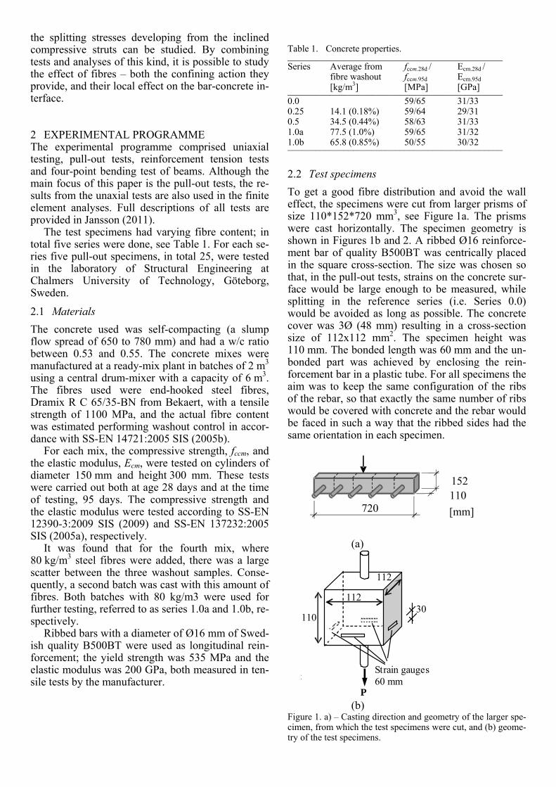
To get a good fibre distribution and avoid the wall effect, the specimens were cut from larger prisms of size 110*152*720 mm3, see Figure 1a. The prisms were cast horizontally. The specimen geometry is shown in Figures 1b and 2. A ribbed Ø16 reinforce-ment bar of quality B500BT was centrically placed in the square cross-section. The size was chosen so that, in the pull-out tests, strains on the concrete sur-face would be large enough to be measured, while splitting in the reference series (i.e. Series 0.0) would be avoided as long as possible. The concrete cover was 3Ø (48 mm) resulting in a cross-section size of 112x112 mm2. The specimen height was 110 mm. The bonded length was 60 mm and the un-bonded part was achieved by enclosing the rein-forcement bar in a plastic tube. For all specimens the aim was to keep the same configuration of the ribs of the rebar, so that exactly the same number of ribs would be covered with concrete and the rebar would be faced in such a way that the ribbed sides had the same orientation in each specimen.
(a)
t
30
Strain gauges 60 mm
112
112
P
110
(b)
Figure 1. a) – Casting direction and geometry of the larger spe-cimen, from which the test specimens were cut, and (b) geome-try of the test specimens.
152110
720 [mm]

2.3 Test setup
The test specimens were supported by a steel frame along the edges of the supported side. To eliminate friction, a layer of Teflon was placed be-tween the support and the specimen; see Figure 2, where a schematic of the test setup is shown.
To monitor the displacements of the reinforce-ment bar, four Linear Variable Displacement Trans-ducers (LVDT) were placed at three different loca-tions – one each at the top and bottom of the rebar, and another two attached to the rebar just below the test specimen; see Figure 2. LVDT1 measured the displacement between points a and b (upper end of rebar and top concrete surface), and the results were used for the residual part of the bond stress-slip curves. LVDT2-3 were mounted on the rebar 25 mm below the bottom concrete surface, and measured the displacement between these points (c and d).
LVDT4 measured the displacement between the bottom of the grip and the machine, including slid-ing of the wedge lock. This gauge was used only to monitor the loading rate. The deformation was ap-plied at a rate of approximately 0.15 mm/min. The data logging frequency was once every five seconds.
In order to investigate the ring/splitting forces, strain gauges were applied on each of the outer sides of the specimens – in total four gauges in series con-nection for each test specimen. As the largest aggre-gate size was 16 mm, strain gauges of length 60 mm were used.
110
50
48
16
Load cell Steel support
Teflon
LVDT2-3
LVDT1
Load direction
LVDT4
Wedge lock
32
a
12
16
b
c
d
25
16
16
Figure 2. Schematic view of the test setup (top) and bottom view of the steel support (bottom).
3 FINITE ELEMENT ANALYSIS The general software Diana was used for the FE analyses, and the cracking behaviour was modelled using the smeared crack model based on total strain and rotating cracks; see (TNO 2011). To be able to investigate the splitting stresses at the interface be-tween matrix and rebar, a bond model developed by Lundgren (2007) was calibrated with the experimen-tal results.
3.1 FE Model
The FE analyses were based on a full 3D model, using tetrahedral mesh elements with base 6.2 mm and height 10 mm. In Figure 3a, an overview of the meshed model with boundary conditions is shown. To prevent the matrix from rotating around the re-bar, four of the concrete nodes connected to the in-terface at the passive side were restricted in move-ment (Figure 3b).
x
y
Figure 3. The 3D model; (a) mesh and boundary conditions, (b) supports at four concrete nodes to prevent rotation around the rebar,

3.2 Constitutive relations
The compressive behaviour of the concrete was assumed as suggested by Thorenfeldt, following the work of Popovic (1973). For each series, the tensile softening behaviour (σ-w relation) of the concrete was obtained experimentally by conducting uni-axial tensile testing (UTT) on notched cylinders. The cyl-inders had a height h = 100 mm and a diameter d = 100 mm, and the depth of the notch at the mid-section was 10 mm. The average σ-w relations for all series are shown in Figure 4.
The σ-ε relations that are needed for the smeared crack model were obtained from the σ-w relations, by smearing out the crack, w, over a distance, h, the crack-band width. A multi-linear approach in TNO (2011) was used. The crack-band width is generally chosen as the width of one element row, with the as-sumption that the cracks will localize within these elements. This was observed for Series 0.0 and 0.25, while for the SCSFRC with higher fibre content it was noted that the cracks did not seem to localize within this area. This is due to the nature of fibre re-inforcement; i.e. after cracking, large stresses are still transferred across the crack into the elements adjacent to the actual crack, and thus those elements may still be subjected to large strains. Choosing a larger value for the crack-band width means that the dissipated energy in the analyses will decrease. Looking at the σ-w relationship shown in Figure 4, though, it is seen that the stress in the fibre concrete stays almost constant up to w = 0.8 mm. For Se-ries 1.0a and 1.0b, the high residual stress-transferring capacity will not be meaningfully af-fected by using a larger value of h, and since the dif-ference between peak stress and residual stress up to w = 0.8 mm is quite small, the cracked elements do not lose enough capacity for surrounding elements to be unloaded. This is mainly due to the assumption of homogeneous distribution of material properties. To model cracking in concrete with high fibre volumes in a more realistic way, the micro scale probably needs to be modelled. Then a fibre could be looked upon as a rebar anchored in plain concrete; the con-crete surrounding it may crack. However, due to time limitations, this was not done in the present study. Thus, for all the analyses in this study, the adopted crack-band width was h = 6.2 mm. This choice proved to yield analysis results in good agreement with the bond stress-slip curves from the experiments.
0.0
0.25
0.5
1.0a
Series 1.0b
0.0
1.0
2.0
3.0
4.0
0 0.2 0.4 0.6 0.8
Str
ess
[MP
a]
Crack width [mm]
Figure 4. Average σ-w curves for each series, initial part.
3.3 Bond model
The bond model used was developed by Lundgren (2007), where more details may be found. The model is capable of describing both the bond stress and slip along the rebar, and the normal stresses and corresponding normal displacement at the interface layer. The model is a frictional model, using elasto-plastic theory to describe the relations between the stresses and the deformations. The stresses are lim-ited by two yield functions: one describing the fric-tion (including adhesion), and one describing the upper limit at a pull-out failure.
4 COMPARISON OF EXPERIMENTAL AND NUMERICAL RESULTS
4.1 Experimental results
The average ascending part of the curves is shown in Figure 5, and the individual bond stress-slip curves for each specimen are shown in Figure 6. Up to peak, the results were plotted against the slip meas-ured on the active side; for the residual part the slip measured on the passive side was used. It is seen that the series with the lowest compressive strength, 1.0b, exhibits the lowest stiffness as well as the low-est maximum value. Note, however, that this series showed the lowest compressive strength, fcm.95d = 55 MPa compared with 63-65 MPa for the other series. When normalizing the bond stress with the compressive strength as suggested by Magnus-son (2000), it is seen that all the series show nearly identical initial stiffness and capacity; see Figure 5b.

4.2 Experiments and numerical analyses
The bond model was originally calibrated for nor-mal-strength concrete without fibres (vibrated) and rebar K500ST with diameter Ø = 16mm. Analyses using this original calibration showed results where the pre-peak stiffness was too weak and the peak and residual stresses were unacceptably high. It should be noted that the main focus of the original calibra-tion was anchorage failure, see Lundgren (2007), and thus larger slip values than considered here were of interest. This is probably the main reason for the need of change in calibration, even though some part of it can be attributed to the change from normal vi-brated concrete to self-compacting concrete.
To fit the experimental results from the SCSFRC, the original input had to be changed. First, the ini-tially recommended values of the elastic stiffnesses in the model were increased to fit the initial stiff be-haviour of the experimental bond-slip curves. To de-termine the most appropriate input for , () and the adhesion, fa(), different values were combined until the FE results showed acceptable agreement with the experiments. Detailed information about the calibration can be found in Jansson (2011).
1.0b1.0a
0.0
0.5
0.25
0
5
10
15
20
25
0 0.2 0.4 0.6 0.8 1
Bon
d st
ress
[M
Pa]
Active slip [mm]
Average for each series
(a)
0
0.1
0.2
0.3
0.4
0 0.2 0.4 0.6 0.8 1
Nor
mal
ized
bon
d st
ress
/f
c
Active slip [mm]
1.0b
0.25
0.5
1.0a
0.0
(b)
Figure 5. Bond stress-slip; (a) comparison of the average as-cending branch for each series, and (b) same, but normalized with the compressive strength.
0
5
10
15
20
25
0 0.5 1
Bon
d st
ress
[M
Pa]
Active slip [mm]
Series 0.0
ExpFEA
0
5
10
15
20
25
0 0.5 1 1.5 2Bon
d st
ress
[M
Pa]
Slip [mm]
Series 0.25Exp
FEA
05
10
1520
25
0 0.5 1 1.5 2Bon
d st
ress
[M
Pa]
Slip [mm]
Series 0.5ExpFEA
0
5
10
15
20
25
0 0.5 1 1.5 2
Bon
d st
ress
[M
Pa]
Slip [mm]
Series 1.0aExpFEA
0
5
10
15
20
25
0 0.5 1 1.5 2Bon
d st
ress
[M
Pa]
Slip [mm]
Series 1.0b ExpFEA
Figure 6. Comparing experiments with FE results using the same calibrated input in all analyses. Note the differing scale for Series 0.0.

It seems reasonable to start by assuming that the actual interface zone stays unaffected by the fibre re-inforcement used herein; hence it should be possible to use the same input for all the series. Figure 6 shows comparisons between the FE results and the experiments. In the FE model, the displacement was measured at the same location as the LVDT2-3 were placed on the test specimen; therefore, the displace-ment measured at this location in the experiments, was not adjusted regarding the elastic elongation of the rebar.
It is seen in Figure 6 that the calibrated input worked well for Series 0.0, 0.25 and 0.5 regarding initial stiffness, peak and residual stress. Series 0.0 failed in splitting, both in tests and in analyses. Se-ries 0.25 and 0.5 on the other hand, showed splitting behaviour, but kept some confinement due to the fi-bre reinforcement, again both in tests and in analy-ses. Series 1.0a showed good agreement regarding the initial stiffness and peak stress, while for Se-ries 1.0b the peak stress in the analysis was about 10% higher than the highest stress in any of the tested specimens. Both the series with the highest fi-bre content (Series 1.0a and 1.0b) exhibited pullout failure both in tests and in analyses.
4.2.1 Surface strains and crack pattern One of the benefits with the finite element analy-
ses is the possibility to evaluate the strains on the concrete surface. Due to the homogeneous distribu-tion of material properties in the FE analyses, the strains on all four sides are identical up to the point where the concrete cracks. This is not the case in the experiments where different material properties al-low for variations in the strain magnitudes between the four monitored surfaces. At comparison it was seen that the surface strains in the FEA agreed well with the experiments; see Figure 7 for an example.
Figure 8a shows the main principal strain ε1 in Series 1.0b. It is seen that the cracking starts as two separate actions – one originating from the stresses induced by the inclined compressive struts (a), and the other one resulting from the edge supports on the active side (b). Furthermore, it is seen in the analy-ses that the initial crack pattern on the active side re-sembles the envelope-looking crack pattern found in a simply supported plate/slab described with yield-line theory. It is seen that the concentration of strains in the model (Figure 8a, area b) corresponds with the yield lines shown in Figure 8b. For further loading (right before and beyond peak), the cracks arising from action (a) will dominate in the analyses. This is due to the assumption of homogeneous material properties, which then allows the shortest distance to the surface to dictate the final behaviour. In reality, there is a random distribution of material properties which most likely explains why some cracks in the experiment keep developing diagonally even though
this is the longest distance between the rebar and the concrete surface; see Figure 8c.
0
100
200
300
0 0.2 0.4 0.6 0.8 1
Surf
ace
stra
in [
E-6
]
Slip [mm]
TTG1TTG2TTG3TTG4FEA
Figure 7. Example of the surface strains in Series 1.0b com-pared with the measured strain on each of the four sides in one of the test specimens.
b.
a. c.
(a)
(b)
(c)
Figure 8. (a) Contour plot of the maximum principal strain ε1, here for Series 1.0b, (b) crack pattern in simply supported qua-dratic plate according to yield-line theory, and (c) examples of the crack patterns from Series 1.0a and 0.5.

5 CONCLUSIONS
In the literature there have been contradictory re-ports regarding the effect on bond of fibre rein-forcement. This paper reports on pull-out tests with short embedment length using self-compacting steel-fibre reinforced concrete, and FE analyses of these. Based on this work the following conclusions may be drawn: The fibre reinforcement did not disturb or improve
the bond properties at the interface layer; thus, the pre-peak behaviour seems to be unaffected by the inclusion of the steel fibres.
The confinement was markedly improved by the fibre addition, resulting in an increasing residual capacity for increasing amount of fibre reinforce-ment.
An initially stiffer bond stress-slip behaviour was found, compared with the original calibration for vibrated concrete; thus, SCC appears to improve the local bond of concrete–fibre and concrete–rebar.
The cracking was found to arise from two separate actions, one giving rise to diagonal cracks on the supported active side, and a second originating from the tensile stresses induced by the inclined compressive struts from the bond mechanism.
The crack patterns from the analyses were in good agreement with the experimental ones, and the surface strains were well captured.
The failure modes were well captured by the FE analyses.
REFERENCES
Banthia, N., M. Azzabi, et al. 1993. Restrained Shrinkage Cracking in Fibre-Reinforced Cementitious Composites, Materials and Structures 26: 405-413.
Bigaj-van Vliet, A. J. 2001. Bond of Deformed Reinforcing Steel Bars Embedded in Steel Fiber Reinforced Concrete State-of-the-art Report. Delft Cluster.
Bischoff, P. 2003. Tension Stiffening and Cracking of Steel-Fiber-Reinforced Concrete. Journal of Materials in Civil Engineering 15(2): 174-182.
Chao, S.-H., A.E. Naaman, and G. Parra- Montesinos, J. 2009. Bond Behaviour of Reinforcing Bars in Tensile Strain- Hardening Fiber-reinforced Cement Composites. ACI Structural Journal, 106(6): 897-906.
Grünewald, S. 2004. Performance-based design of self-compacting fibre reinforced concrete. PhD Thesis in De-partment of Structural and Building Engineering, Delft University of Technology.
Jansson, A. 2011. Effects of Steel Fibres on Cracking in Rein-forced Concrete. PhD Thesis in Department of Civil and Environmental Engineering, Chalmers University of Tech-nology, Göteborg.
Lundgren, K. 2007. Effect of corrosion on the bond between steel and concrete: an overview, Magazine of Concrete Re-search, 59 (6): 447-461.
Magnusson, J. 2000. Bond and Anchorage of Ribbed Bars in High-Strength Concrete. PhD Thesis in Division of Con-
crete Structures, Department of Structural Engineering, Chalmers University of Technology. Göteborg.
Noghabai, K. 1998. Effect of tension softening on the perform-ance of concrete structures: experimental, analytical and computational studies. PhD Thesis in Dept. of Civil and Mining Engineering, Div. of Structural Engineering, Luleå University of Technology: Luleå.
Popovics, S. 1973. A numerical approach to the complete stress-strain curve of concrete, Cement and Concrete Re-search 3(5): 583-589.
SIS 2005a. SS-EN 137232:2005 Concrete testing - Hardened concrete - Modulus of elasticity in compression. Swedish Standards Institute (SIS).
SIS 2005b. SS-EN 14721:2005 Test method for metallic fibre concrete - Measuring the fibre content in fresh and hard-ened concrete. Swedish Standards Institute (SIS).
SIS 2009. SS-EN 12390-3:2009 Testing hardened concrete - Part 3: Compressive strength of test specimens. Swedish Standards Institute (SIS).
TNO 2011. DIANA - Finite Element Analysis, User's Manual, release 9.4.3.
Related Documents