GHGT-10 Boiling liquid expanding vapour explosion in CO 2 Small scale experiments Bjerketvedt, D. 1,2∗ , Egeberg, K. 1,3 , Ke, W. 1 , Gaathaug, A. 1 Vaagsaether, K. 1 and Nilsen S.H. 3 1 Telemark University College, Porsgrunn, Norway 2 Tel-Tek, Porsgrunn, Norway 3 Statoil Research Centre, Porsgrunn, Norway Abstract Carbon capture and storage systems require handling large volumes of high pressure CO 2 . Having thorough knowledge of the related hazards is essential, as is knowing how to prevent, detect, control and mitigate accidents. This paper gives a short description of CO 2 Boiling Liquid Expanding Vapour Explosions (BLEVEs) and presents results from preliminary, small scale experiments with CO 2 BLEVEs. The mechanism of superheated liquid CO 2 boiling is not fully understood. Analogies can be made between gas explosions and rapid phase transitions occurring in BLEVEs. The experiments indicate that violent boiling may occur before the spinodal point is reached. Shock waves in the experiments were generated by the decompression of the vapour in the vessel before rupture. However, our recent theoretical models show that boiling also will contribute to shock strength. We observed fragment velocities up to approximately 100 m/s. Such fragments are a serious hazard. Large scale tests and laboratory tests are needed for validation of equation of state models and for the development of computational fluid dynamic codes for use in risk analysis. Keywords: Safety; Carbon Capture and Storage; BLEVE, explosion; ∗ Corresponding author. Tel.: +47 3557 5232 ; fax: +47 3557 5001. E-mail address: [email protected]. c ⃝ 2011 Published by Elsevier Ltd. Energy Procedia 4 (2011) 2285–2292 www.elsevier.com/locate/procedia doi:10.1016/j.egypro.2011.02.118 Open access under CC BY-NC-ND license.

Welcome message from author
This document is posted to help you gain knowledge. Please leave a comment to let me know what you think about it! Share it to your friends and learn new things together.
Transcript
Energy Procedia 00 (2010) 000–000
Energy Procedia
www.elsevier.com/locate/XXX
GHGT-10
Boiling liquid expanding vapour explosion in CO2
Small scale experiments
Bjerketvedt, D. 1,2∗, Egeberg, K.1,3, Ke, W.1, Gaathaug, A.1 Vaagsaether, K.1 and Nilsen S.H.3
1 Telemark University College, Porsgrunn, Norway 2 Tel-Tek, Porsgrunn, Norway
3 Statoil Research Centre, Porsgrunn, Norway
Elsevier use only: Received date here; revised date here; accepted date here
Abstract
Carbon capture and storage systems require handling large volumes of high pressure CO2. Having thorough knowledge of the related hazards is essential, as is knowing how to prevent, detect, control and mitigate accidents. This paper gives a short description of CO2 Boiling Liquid Expanding Vapour Explosions (BLEVEs) and presents results from preliminary, small scale experiments with CO2 BLEVEs. The mechanism of superheated liquid CO2 boiling is not fully understood. Analogies can be made between gas explosions and rapid phase transitions occurring in BLEVEs. The experiments indicate that violent boiling may occur before the spinodal point is reached. Shock waves in the experiments were generated by the decompression of the vapour in the vessel before rupture. However, our recent theoretical models show that boiling also will contribute to shock strength. We observed fragment velocities up to approximately 100 m/s. Such fragments are a serious hazard. Large scale tests and laboratory tests are needed for validation of equation of state models and for the development of computational fluid dynamic codes for use in risk analysis.
© august 31, 2010 Elsevier Ltd. All rights reserved
Keywords: Safety; Carbon Capture and Storage; BLEVE, explosion;
∗ Corresponding author. Tel.: +47 3557 5232 ; fax: +47 3557 5001.
E-mail address: [email protected].
c⃝ 2011 Published by Elsevier Ltd.
Energy Procedia 4 (2011) 2285–2292
www.elsevier.com/locate/procedia
doi:10.1016/j.egypro.2011.02.118
Open access under CC BY-NC-ND license.

2 Bjerketvedt et al./ Energy Procedia 00 (August 31, 2010) 000–000
1. Introduction
The processing, storage and transport of CO2 have been safely carried out for many decades in the medical and food industries as well as in enhanced oil recovery (EOR) activities. Carbon capture and storage (CCS) systems will require increased volumes of carbon dioxide under high pressure and may be close to residential areas. It is essential to thoroughly understand the hazards related to systems containing large quantities of pressurized CO2 and how to prevent, detect, control and mitigate accidents.
Figure 1 A 1.9 kg fragment from CO2 BLEVE flew through a 2-layer steel roof and landed 35 m from the explosion site [1].
Carbon dioxide is classified as neither flammable nor toxic, although it may cause intoxication at elevated concentrations. Asphyxiation is generally considered the major hazard of CO2. However, a severe hazard associated with pressurized CO2 is the Boiling Liquid Expanding Vapour Explosion (BLEVE). The Centre for Chemical Process Safety defines a BLEVE as “a sudden release of a large mass of pressurized superheated liquid to the atmosphere.” A CO2 BLEVE event may cause blast waves, dangerous flying fragments, asphyxiation or intoxication at high concentrations in air, and frostbite burns. In case of a BLEVE, facilities might suffer heavy material damage and working personnel might suffer severe injuries and even fatalities. Risk studies and severe accidents show that the hazard from a CO2 BLEVE must be taken seriously, even though it is a very unusual event.
A small CO2 BLEVE occurred in Norway in 2008 [1] when a fire extinguisher containing 5 kg of liquid CO2 was thrown into a waste skip bin (dumpster). Unfortunately, the skip was sent to a waste-to-energy plant where the waste was shredded before it was burned. The shredder punctured the fire extinguisher and the aluminum cylinder burst into several fragments. One of the fragments, weighing 1.9 kg, flew through a two-layer steel roof and landed 35 m from the shredder. Another catastrophic rupture of a CO2 liquid tank occurred in Worms, Germany, in 1988 [2]. This accident caused three fatalities, three months production loss and significant material damage.
Risk analyses and risk based safety management are in Statoil considered to be the key elements of safe design and operation. Understanding the mechanisms and phenomena in a CO2 BLEVE is important, both to prevent such accidents from occurring and as basis for consequence calculations in risk assessment studies. The above mentioned events clearly demonstrate the hazard potential of CO2 BLEVE events. After the incident in Norway, and also as a part of Statoil’s research activity on CO2 safety, it was decided to perform a literature review on BLEVE mechanisms in CO2 and to carry out small-scale laboratory tests with CO2 BLEVEs
This paper gives a brief description of BLEVE theories and mechanisms. In addition, results from preliminary small scale experiments with CO2 BLEVEs are presented.
2286 D. Bjerketvedt et al. / Energy Procedia 4 (2011) 2285–2292
Bjerketvedt et al. / Energy Procedia 00 (August 31, 2010) 000–000 3
2. Mechanisms
The most recent review article on BLEVEs was written by Abbasi and Abbasi [3]. They discuss the Super Heat Temperature (SLT) BLEVE mechanisms. When a saturated liquid undergoes a rapid pressure reduction (i.e., volume expansion), the fluid will become superheated and the temperature in the liquid will be higher than the saturation temperature. From thermodynamics it is known that a state becomes inherently unstable as the superheated liquid reach the spinodal curve [(δp/δρ)T = 0] and rapid boiling will then take place within 1 ms [3]. The lowest saturation temperature that can reach the spinodal curve, when the liquid is expanded to 1 atm, is known as the “superheat limit temperature” (SLT). If the expansion starts from a temperature below SLT, the boiling process will be relatively slow. However, BLEVEs can still occur for initial temperatures below SLT, according to Prugh [4].
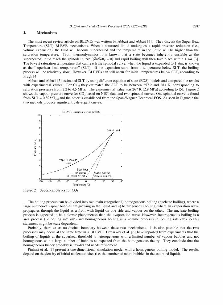
Abbasi and Abbasi [5] estimated SLT by using different equation of state (EOS) models and compared the results with experimental values. For CO2 they estimated the SLT to be between 257.2 and 283 K, corresponding to saturation pressures from 2.2 to 4.5 MPa. The experimental value was 267 K (2.9 MPa) according to [5]. Figure 2 shows the vapour pressure curve for CO2 based on NIST data and two spinodal curves. One spinodal curve is found from SLT = 0.895*Tcrit and the other is established from the Span-Wagner Technical EOS. As seen in Figure 2 the two methods produce significantly divergent curves.
Figure 2 Superheat curves for CO2
The boiling process can be divided into two main categories: i) homogeneous boiling (nucleate boiling), where a large number of vapour bubbles are growing in the liquid and ii) heterogeneous boiling, where an evaporation wave propagates through the liquid as a front with liquid on one side and vapour on the other. The nucleate boiling process is expected to be a slower phenomenon than the evaporation wave. However, heterogeneous boiling is a area process (i.e boiling rate /m2) and homogeneous boiling is a volume process (i.e. boiling rate /m3) so this statement might be scale dependent.
Probably, there exists no distinct boundary between these two mechanisms. It is also possible that the two processes may occur at the same time in a BLEVE. Ermarkov et al. [6] have reported from experiments that the boiling of liquids at the superheat threshold is heterogeneous with a limited number of vapour bubbles and not homogenous with a large number of bubbles as expected from the homogeneous theory. They conclude that the homogeneous theory probably is invalid and needs refinement.
Pinhasi et al. [7] present a one-dimensional simulation model with a homogenous boiling model. The results depend on the density of initial nucleation sites (i.e. the number of micro bubbles in the saturated liquid).
D. Bjerketvedt et al. / Energy Procedia 4 (2011) 2285–2292 2287
4 Bjerketvedt et al./ Energy Procedia 00 (August 31, 2010) 000–000
Reinke and Yadigaroglu [8] report results from laboratory experiments with explosive vaporization of superheated liquids by boiling fronts. The vapour generation could not be linked to a single instability or nucleation mechanism. They also claim that the phase change at the boiling front cannot be described as an isentropic process.
Boiling of superheated droplets has been studied extensively by Sheperd and Sturtevant [9] and Frost and Sturtevant [10]. They found that the Landau-Darrieus (L-D) instability was important for the surface area of the boiling front. It is expected that the L-D instabilities increase the surface area of the boiling front and thereby increase the boiling rate. The L-D instability is also a mechanism that increases the burning rate of laminar premixed flames. Frost and Sturtevant [10] showed that this instability mechanism can be suppressed by increased pressure and that a spherical system is more stable than a planar system.
Frost et al. [11], Simões-Moreira and Shepherd [12], Le Métayer et al. [13] and Perrier [14] discuss Rankin-Huginoit relations (mass, momentum and energy conservation) across a boiling front. Simões-Moreira and Shepherd observed boiling fronts in their experiments when the superheat limit was exceeded. Both subsonic (i.e. weak solution) and choked flow (i.e. CJ solution) were seen after the boiling front. A heterogeneous boiling front seems to behave like a flame (i.e. deflagration) in a premixed gas. Le Métayer et al. [13] used a reactive Riemann solver to model an evaporation front. There appear to be several analogies (i.e. instability mechanisms and Rankin-Huginoit relations ) between gas explosion theories (deflagrations) and the rapid phase transitions occurring in BLEVEs.
3. Experimental set-up
The experiments were conducted in a small vessel made out of a plastic tube enclosed between two flanges by a pneumatic cylinder. The tube was 60 mm or 100 mm long and the outer diameter was 40 mm. A piece of solid CO2
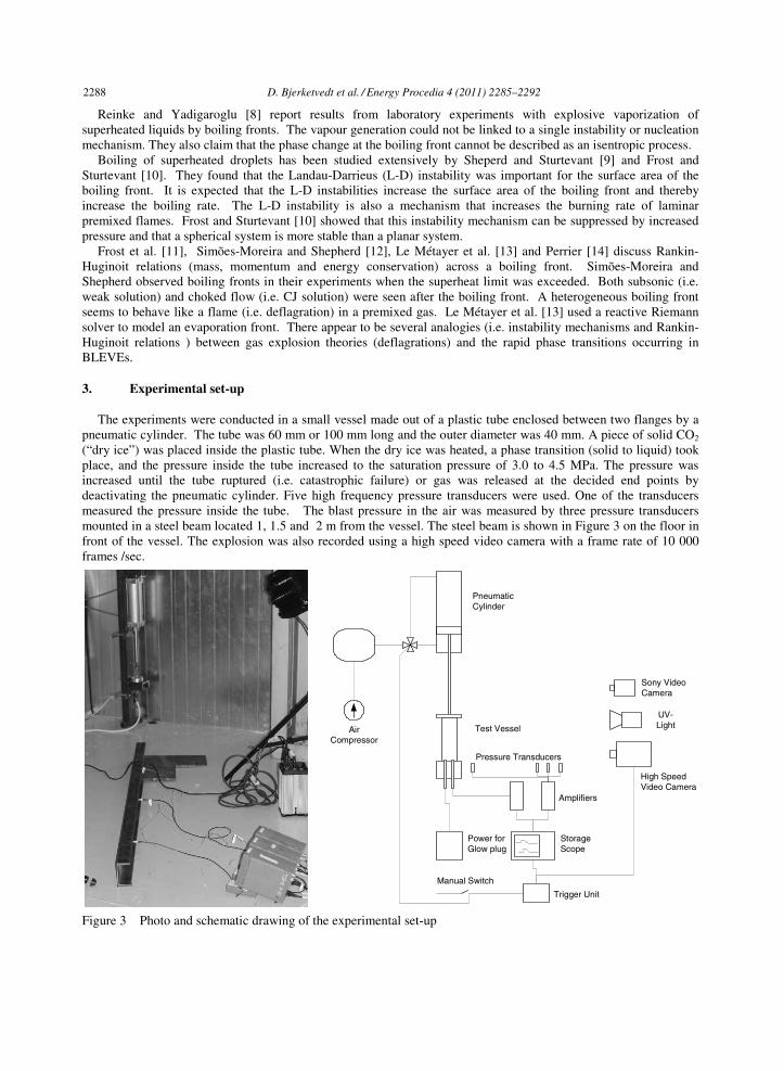
(“dry ice”) was placed inside the plastic tube. When the dry ice was heated, a phase transition (solid to liquid) took place, and the pressure inside the tube increased to the saturation pressure of 3.0 to 4.5 MPa. The pressure was increased until the tube ruptured (i.e. catastrophic failure) or gas was released at the decided end points by deactivating the pneumatic cylinder. Five high frequency pressure transducers were used. One of the transducers measured the pressure inside the tube. The blast pressure in the air was measured by three pressure transducers mounted in a steel beam located 1, 1.5 and 2 m from the vessel. The steel beam is shown in Figure 3 on the floor in front of the vessel. The explosion was also recorded using a high speed video camera with a frame rate of 10 000 frames /sec.
Figure 3 Photo and schematic drawing of the experimental set-up
Pneumatic Cylinder
High SpeedVideo Camera
UV-Light
Storage Scope
Trigger Unit
Power forGlow plug
Air Compressor
Amplifiers
Pressure Transducers
Manual Switch
Sony Video Camera
Test Vessel
2288 D. Bjerketvedt et al. / Energy Procedia 4 (2011) 2285–2292

Bjerketvedt et al. / Energy Procedia 00 (August 31, 2010) 000–000 5
4. Results and Discussion
A typical result from a catastrophic failure test is shown in Figure 4. This figure shows pictures from the high speed video alongside the pressure measured inside the tube. The letter indicates the time of the picture. In Figure 4a, we see that the tube starts to crack on the left side in the longitudinal direction. Figure 4b, 0.1 ms later, shows
Figure 4 Pressure recorded inside the tube versus time and high speed video snapshots at the times indicated by letter a to f.
a)
10000 fps
b) c)
d) e) f)
a)
10000 fps
b) c)
d) e) f)
-0.5 0 0.5 1 1.5 2 2.5 3 3.50
0.5
1
1.5
2
2.5
3
3.5
4
Time (ms)
Pre
ssur
e (M
Pa)
a
bc d
e
f
g
h
D. Bjerketvedt et al. / Energy Procedia 4 (2011) 2285–2292 2289
6 Bjerketvedt et al./ Energy Procedia 00 (August 31, 2010) 000–000
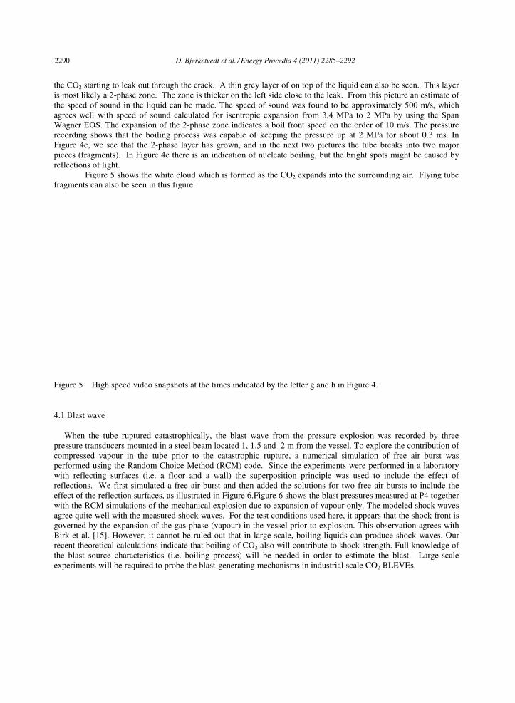
the CO2 starting to leak out through the crack. A thin grey layer of on top of the liquid can also be seen. This layer is most likely a 2-phase zone. The zone is thicker on the left side close to the leak. From this picture an estimate of the speed of sound in the liquid can be made. The speed of sound was found to be approximately 500 m/s, which agrees well with speed of sound calculated for isentropic expansion from 3.4 MPa to 2 MPa by using the Span Wagner EOS. The expansion of the 2-phase zone indicates a boil front speed on the order of 10 m/s. The pressure recording shows that the boiling process was capable of keeping the pressure up at 2 MPa for about 0.3 ms. In Figure 4c, we see that the 2-phase layer has grown, and in the next two pictures the tube breaks into two major pieces (fragments). In Figure 4c there is an indication of nucleate boiling, but the bright spots might be caused by reflections of light. Figure 5 shows the white cloud which is formed as the CO2 expands into the surrounding air. Flying tube fragments can also be seen in this figure.
Figure 5 High speed video snapshots at the times indicated by the letter g and h in Figure 4.
4.1.Blast wave
When the tube ruptured catastrophically, the blast wave from the pressure explosion was recorded by three pressure transducers mounted in a steel beam located 1, 1.5 and 2 m from the vessel. To explore the contribution of compressed vapour in the tube prior to the catastrophic rupture, a numerical simulation of free air burst was performed using the Random Choice Method (RCM) code. Since the experiments were performed in a laboratory with reflecting surfaces (i.e. a floor and a wall) the superposition principle was used to include the effect of reflections. We first simulated a free air burst and then added the solutions for two free air bursts to include the effect of the reflection surfaces, as illustrated in Figure 6.Figure 6 shows the blast pressures measured at P4 together with the RCM simulations of the mechanical explosion due to expansion of vapour only. The modeled shock waves agree quite well with the measured shock waves. For the test conditions used here, it appears that the shock front is governed by the expansion of the gas phase (vapour) in the vessel prior to explosion. This observation agrees with Birk et al. [15]. However, it cannot be ruled out that in large scale, boiling liquids can produce shock waves. Our recent theoretical calculations indicate that boiling of CO2 also will contribute to shock strength. Full knowledge of the blast source characteristics (i.e. boiling process) will be needed in order to estimate the blast. Large-scale experiments will be required to probe the blast-generating mechanisms in industrial scale CO2 BLEVEs.
Fragment
g) h)
2290 D. Bjerketvedt et al. / Energy Procedia 4 (2011) 2285–2292

Bjerketvedt et al. / Energy Procedia 00 (August 31, 2010) 000–000 7
Figure 6 a) Illustration of blast modeling by superposition of three charges. Charge 1 is a free air bust charge, charge 2 is a floor reflection and charge 3 is a wall reflection. b) Pressure versus time recorded during vapour explosion with the RCM simulation superimposed
4.2.Fragments
In a BLEVE, fragments such as part of a pressure vessel can travel long distances and are capable of generating severe domino events, causing severe injuries and even fatalities. According to Baker et al. [16] the kinetic energy in the fragments will typically be 10% of the energy released in the explosion. Baum [17] has done experiments with end caps from failing pressure vessels containing high temperature liquids. Baum presented an upper limit value for fragment velocities. He measured fragment velocities up to 87 m/s. In our experiments, we observed fragment velocities up to approximately 100 m/s. The fragments can be seen in Figure 5.
5. Conclusions
A literature review of BLEVE theories and mechanisms has been carried out and small scale CO2 BLEVE experiments have been performed. From this work, we make the following conclusions:
• The detailed mechanism of boiling of superheated metastable liquid CO2 is not understood. The boiling process might be heterogeneous or homogeneous, or a combination of the two.
• In the literature, the thermodynamic data for CO2, such as superheat limit temperature are scattered and dependent on the equation of state (EOS) applied.
• There seem to be several analogies between gas explosion theories (deflagrations) and rapid phase transitions occurring in BLEVEs.
• In the present experiments, the expansion seems to stabilize at a pressure around 2 MPa for a short period of time. This indicates that violent boiling may occur before the spinodal point is reached. In the video recordings, the boiling appears to mainly be of a heterogeneous type with an evaporation front.
• The shock waves in the experiments were caused by the decompression of the vapour in the vessel prior to the rupture. However, the duration of blast waves was increased due to the boiling. Our recent theoretical models indicate that boiling also will contribute to shock strength.
• We observed fragment velocities up to approximately 100 m/s. Such fragments represent a serious hazard.
1.5 2 2.5 3 3.5 4 4.5 5 5.5 6-5
0
5
10
Time (msec)
Pre
ssur
e (k
Pa)
RCM
P4 at 1.05 m
D. Bjerketvedt et al. / Energy Procedia 4 (2011) 2285–2292 2291
8 Bjerketvedt et al./ Energy Procedia 00 (August 31, 2010) 000–000
• Since a BLEVE can not be considered as a point source and the phase transition will depend on how fast CO2 boils, we need to understand the boiling mechanisms in order to estimate the blast, fragments and dispersion of CO2.
• Large scale tests and laboratory tests are needed for validation of EOS models and for the development of CFD codes for use in risk analysis.
References
- [1] Aas T, Østfold Energi. Sarpsborg, Norway, Private communication, 2008 - [2] Clayton WE, Griffin ML. Catastrophic failure of a liquid carbon dioxide storage vessel, Process Safety
Progress 1994; 13:202 - [3]Abbasi T, Abbasi SA. The boiling liquid expanding vapour explosion (BLEVE): Mechanism, consequence
assessment, management, Journal of Hazardous Materials 2007; 141:3: 489-519 - [4] Prugh RW. Quantify BLEVE hazards, Chemical Engineering Progress 1991; 87: 2: 66-72 - [5] Abbasi T, Abbasi SA. Accidental risk of superheated liquids and a framework for predicting the superheat
limit, Journal of Loss Prevention in the Process Industries 2007, 20 : 2: 165-181 - [6] Ermakov GV, Lipnyagov EV, Perminov SA, Gurashkin AL. Heterogeneous boiling-up of superheated liquid at achievable superheat threshold, J. Chem. Phys. 2009; 131:031102:1-3 - [7]Pinhasi GA, Ullmann A, Dayan A. 1D plane numerical model for boiling liquid expanding vapor explosion
(BLEVE), International Journal of Heat and Mass Transfer 2007; 50:23-24:4780-4795 - [8]Reinke P, Yadigaroglu G. Explosive vaporization of superheated liquids by boiling fronts, International Journal
of Multiphase Flow 2001; 27: 9:1487-1516 - [9] Shepherd JE, Sturtevant, B. Rapid evaporation at the superheat limit, J Fluid Mech. 1982; 122: 379-402 - [10] Frost D, Sturtevant B. Effect of ambient pressure on the instability of a liquid boiling explosively at the
superheat limit, Journal of Heat Transfer Transactions of ASME 1986; 108: 2:418-424 - [11] Frost DL, Lee JHS, Ciccarelli G. The use of hugoniot analysis for the propagation of vapor explosion waves.
Shock waves 1991; 1: 99-110. - [12] Simões-Moreira, JR, Shepherd JE. Evaporation waves in superheated dodecane, J. Fluid Mech. 1999;
382:63–86 - [13] Le Métayera O, Massonia J, Saurela R. Modelling evaporation fronts with reactive Riemann solvers,
Journal of Computational Physics 2005; 205:2:567-610 - [14] Perrier V. The Chapman-Jouguet closure for the Riemann problem with vaporization, SIAM Journal on
Applied Mathematics 2008; 68:5 -[15] Birk AM , Davisona C, Cunninghama M. Blast overpressures from medium scale BLEVE tests, Journal of
Loss Prevention in the Process Industries 2007; 20: 3: 194-206 - [16]Baker, W. E. et al. Explosion hazards and evaluation, New York: Elsevier Science Publishers; 1983 - [17]Baum, MR. Failure of a horizontal pressure vessel containing a high temperature liquid: the velocity of end-
cap and rocket missiles, Journal of Loss Prevention in the Process Industries 1999; 12: 2: 137-145
2292 D. Bjerketvedt et al. / Energy Procedia 4 (2011) 2285–2292
Related Documents