Boeing Model 464L Strategic Weapons System (Dyna-Soar) As requested by the United States Air Force, the Boeing Airplane Company has developed a concept for Dyna Soar I to provide significant advances in military technology and aimed toward the subsequent application of that technology to military hardware. The Boeing approach achieves high flexibility by early development of one basic hypersonic boost-glide vehicle usable in a wide range of technical exploration of military interest. The technology to be demonstrated by this vehicle and supporting systems is directed to achieve three fundamental capabilities: 1. The ability to efficiently and economically launch into hypersonic flight or orbit both men and tonnages of useful equipment. 2. The ability of hypersonic glide techniques and equipment to recover the men and equipment at designated locations. 3. The ability to control space traffic involving large numbers of vehicles including those being launched, those being recovered, and those on sustained missions, plus the ability to recognize and track hostile traffic in space. In the DS-I Program, the basic vehicle is used in a wide range of test missions and is later adopted without basic redesign to utilizations in strategic missions. These missions could conceivably cover a wide range of possibilities, the relative merits of which will be studied in conjunction with the Air Force during the DS-I programs. Some examples are: 1. Establishment of a global reconnaissance and early warning system as a progressive outgrowth of SAGE and existing early warning systems. 2. Establishment of a chain of television relay stations for meteorological surveys and research. 3. Construction of large space stations by carrying each part separately into orbital position with Dyna Soar vehicles.

Boeing Model 464L Strategic Weapons System
Nov 30, 2015
Details of the Boeing entry into the USAF Dyna-Soar competition.
Welcome message from author
This document is posted to help you gain knowledge. Please leave a comment to let me know what you think about it! Share it to your friends and learn new things together.
Transcript

Boeing Model 464L Strategic Weapons System (Dyna-Soar)
As requested by the United States Air Force, the Boeing Airplane Company has developed a concept for Dyna Soar I to provide significant advances in military technology and aimed toward the subsequent application of that technology to military hardware. The Boeing approach achieves high flexibility by early development of one basic hypersonic boost-glide vehicle usable in a wide range of technical exploration of military interest. The technology to be demonstrated by this vehicle and supporting systems is directed to achieve three fundamental capabilities: 1. The ability to efficiently and economically launch into hypersonic flight or orbit both men and tonnages of useful equipment. 2. The ability of hypersonic glide techniques and equipment to recover the men and equipment at designated locations. 3. The ability to control space traffic involving large numbers of vehicles including those being launched, those being recovered, and those on sustained missions, plus the ability to recognize and track hostile traffic in space. In the DS-I Program, the basic vehicle is used in a wide range of test missions and is later adopted without basic redesign to utilizations in strategic missions. These missions could conceivably cover a wide range of possibilities, the relative merits of which will be studied in conjunction with the Air Force during the DS-I programs. Some examples are: 1. Establishment of a global reconnaissance and early warning system as a progressive outgrowth of SAGE and existing early warning systems. 2. Establishment of a chain of television relay stations for meteorological surveys and research. 3. Construction of large space stations by carrying each part separately into orbital position with Dyna Soar vehicles.

4. Placement of nuclear warheads into orbit for potential use in (a) retaliatory attacks on enemy territory, (b) attacks against enemy satellite systems, (c) defensive interceptions against weapons attacking the vehicles, and (d) defensive interceptions against ballistic missiles or other vehicles attacking United States territory. Boeing is proposing at this time a specific preliminary design for the DS-I system. In the vehicle, extensive application has been made of the Company's background in hypersonic vehicle research, wind tunnel testing, structural hot tests. The ability to carry a man into orbit and return has been a central consideration in the Boeing design. Boeing maintains a comprehensive view of the over-all Dyna Soar I technical objectives of which the vehicle is but a part. These are seen as extending over a broad range of exploration and experiment required by the Air Force designated parameters of interest. Included is the hardware development of all components needed for later use in follow-on military applications. It is planned that maximum use be made initially of available hardware with parallel developments which can be extrapolated far into the future without major changes in scale or function. The Dyna Soar I Program is a technical exploration of massive proportions resulting in hardware and data for later application in strategic space weapon systems. The initial (Dyna Soar I) program has already been designated as a comprehensive technical mission resulting in hardware and data for application in strategic global weapon systems. Boeing has examined in some detail two candidate weapon systems which could evolve from the Dyna Soar 1: one involving early boost-glide hardware of limited range (Dyna Soar II); the other involving orbital vehicles of global capability (Dyna Soar III). The Dyna Soar II concept employs a combination of a manned reconnaissance boost-glide vehicle and an unmanned weapon boost-glide
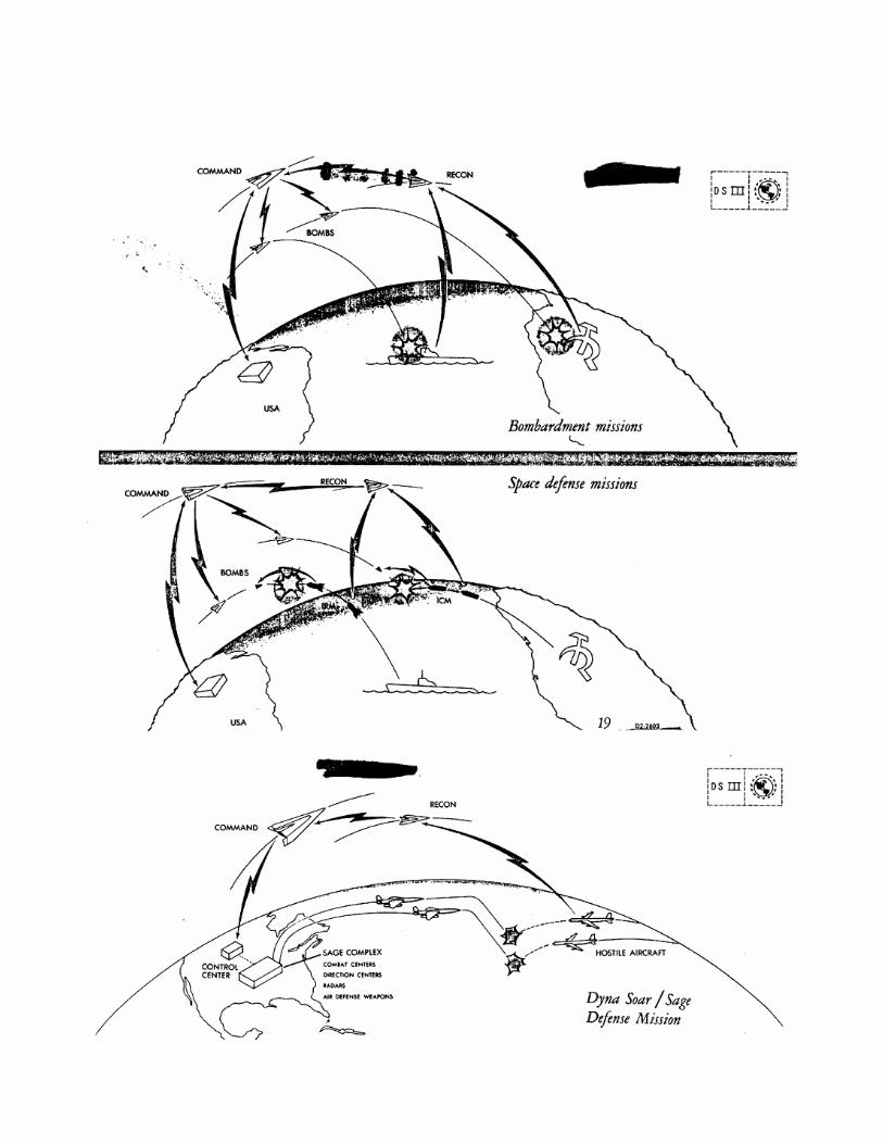
vehicle in a fleet operation out to ranges of the order of 6,000 miles. Such fly-over missions will compel the use of some landing and/or launching sites outside the United States. It is therefore recognized that the DS-II system may not provide optimum utilization of the DS-I technology. However, it does offer the significant advantage of immediate and direct application of early DS-I hardware development into military capability. The Dyna Soar III weapon system concept employs satellite boost-glide vehicles in the form of a manned (command) vehicle, an unmanned reconnaissance vehicle, and an unmanned weapon vehicle. These vehicles are deployed in large numbers in various orbits to achieve world-wide reconnaissance and bombardment capability. Re-entry techniques involved in recovering both manned and unmanned vehicles from orbit will have been developed as part of the DS-I Program. However, the DS-III concept introduces two new requirements which fall outside the capabilities of the standard building block hardware developed in the DS-I Program. The first is for a larger boost-glide vehicle. In orbital missions extending over many days and involving a multiplicity of human operations it becomes profitable to rely on more extensive application of space-borne equipment and more than one occupant in the command vehicle. It is expected that the new vehicle will constitute little more than a scale-up of the basic DS-I vehicle and that the re-entry and landing techniques developed in DS-I will continue to apply. The second new requirement is for a recoverable booster for DS-III vehicles. Analysis of a large scale dynamic global system predicts landings and launchings frequent enough to make recoverable boost hardware appear economically attractive.


TRANSITION FROM DS-I TO DS-II WEAPON SYSTEM DS-II is a weapon system evolving from the DS-I Program with a minimum of new development. DS-II as conceived in this proposal utilizes techniques demonstrated in the DS-I Program and much of the airborne hardware developed during the DS-I Program. The glider vehicle is essentially the same as the DS-1 glider, operating either unmanned or with a single crew member. The boost system utilizes the 3-stage boost used in DS-I. Reconnaissance equipment is a production version of breadboard or prototype equipment used in DS-I. The bombardment vehicle consists of an unmanned DS-I glider carrying an integral warhead. The operational ground support equipment used for DS-II has been derived from pre-prototype equipment used during DS-I. Later version of the DS-II weapon system will incorporate more

sophisticated equipment but the basic elements of DS-II are the earliest possible of the DS-I Program. DS-II MISSION A. FLY-OVER RECONNAISSANCE MISSIONS The DS-II reconnaissance vehicle is a 6,000 to 8,000-mile boost glider. It can be either manned or unmanned. The 6,000-mile glider uses DS-I boosters; 8,000 mile range is achieved with improved boosters. The manned version has the capability of examining selected target areas and making on-the-spot evaluations of the enemy situation. The unmanned version is used for peacetime reconnaissance carrying large-loads of reconnaissance equipment to collect data for later evaluation on the ground. DS-II reconnaissance supplements other reconnaissance and intelligence information; for example, general information obtained from satellite vehicles is supplemented by the more detailed evaluation of selected areas taking advantage of the lower altitude of DS-II. Reconnaissance systems used in DS-II include: 1. High-Resolution Coherent Radar An antenna 15 feet in length is mounted externally on the vehicle. Negligible range loss is obtained from this configuration. Pitch stabilization is obtained by flying the vehicle at zero angle of attack over the selected target area. This attitude can be maintained for 20 seconds at a time with essentially no range penalty. Seventy-five foot resolution of ground targets will be obtained over a 25-mile-wide strip. 2. Optical Reconnaissance Conventional cameras or high sensitivity TV cameras for night use are used interchangeably. 3. Electronic Reconnaissance Elint equipment can be installed internally with cut-outs in the lower vehicle surface for antennas. B. BOMBING MISSIONS Strategic bombing during the DS-II time period will be accomplished by

various complementary weapon systems. These include ICBM's, manned bombers and glide weapons evolving from the DS-I program. The basic bombardment vehicle proposed for DS-II is the unmanned DS-I glider carrying a warhead. This weapon vehicle carries its own guidance system to navigate it to the pre-selected target using intelligence information available from reconnaissance or other sources prior to its launching. The guidance system would consist of an inertial auto navigator plus an ATRAN map-marching radar to correct inertial guidance errors by fixes taken about 100 miles from target. A CEP of 1500 feet is obtained if adequate radar mapping data in the target area is available. However, the basic bombardment operation used here to illustrate DS-II potentialities involves use of the DS-II reconnaissance vehicle in combination with both glide weapons and other bombing weapons. This concept is described in the next section. OPERATIONAL CONCEPT A. USE OF DS-II WEAPONS SEPARATELY In this mode of operations DS-II reconnaissance vehicles fly over Russia, landing either at foreign bases or, alternatively, launched from these bases and landing in the United States or contiguous bases. This latter course is preferable during wartime so that data obtained on the flights can be used immediately to provide target designation for strategic bombing weapons stationed in the United States. The DS-II glide weapon will be one of the vehicles so used. B. FLEET OPERATION OF DS-II WEAPONS In this operation both manned reconnaissance and bombing weapons are launched toward the target area. The reconnaissance vehicles arrive at selected target areas first. The crew identifies target aim points on their radar or optical presentations and transmits correction signals to the bombing weapons. Each reconnaissance operator controls one or more approaching missiles. Four types of bombardment for which this fleet mode of operation of DS-II can be used are:
1. Bombing of targets whose locations are not accurately known. 2. Selection of targets for bombing based on their present appearance; i.e., presence or absence of aircraft on a runway. 3. Pinpoint bombing of underground installations. (An improved form of terminal guidance can be provided for this type of operation.) 4. Bomb damage assessment with follow-up bombing of targets not destroyed in the first phase of war. C. LAUNCH AND LANDING BASES The map on page 15 shows preliminary choice of base locations used for DS-II. Bases indicated with solid symbols are those which permit coverage of all of Russia using 6000-mile vehicles. The open symbols represent bases for an 8000-mile DS-II flight range; the additional range permits use of more satisfactory base locations. D. RECALL CAPABILITY In the bombardment operation warhead missiles would be subject to recall until they start their target dive. Until that time they have the capability of continuing flight to the same landing fields used by reconnaissance vehicles, or of being otherwise diverted or destroyed. SYSTEM CHOICE A. CHOICE OF BOMBARDMENT VEHICLE The bombardment warhead could either be ejected from a reconnaissance vehicle, using the technique demonstrated during DS-I, or launched directly from home base in a DS-I unmanned type vehicle. This latter technique has been used in the above illustration of DS-II concept for the following reasons: Preliminary estimate indicate that the CEP of typical downward-ejected stores will be about 4 miles. This means that control surfaces and guidance equipment will have to be added to the weapon to improve its accuracy. To be effective, the guidance system must be comparable in complexity and weight to that in the carrier vehicle. Total vehicle size, including the warhead, then becomes large enough to justify separate launching.

B. FEATURES OF THE DS-II SYSTEM The DS-II boost glide weapon system chosen as an illustrative example above has certain advantages and disadvantages which should be evaluated carefully early in the Dyna Soar Program. DS-II has the advantage that the basic configuration can evolve rapidly from DS-I. It also has the advantage of lower flight altitude, thus putting it closer to target areas under observation. On the other hand, DS-II will be exposed to problems associated with the hypersonic air environment. Ionization in the boundary layer may prevent utilization of radar and interfere with communication between vehicles. Heating of infrared windows will affect or seriously complicate utilization of infrared reconnaissance. Window heating and boundary layer luminosity may complicate optical and TV reconnaissance. During Phase I studies, final determination of the DS-II Weapon System configuration will occur. The overall program has been arranged to permit elimination of the DS-II system if acceleration of the orbital DS-III concept appears preferable to the Air Force. DYNA SOAR III DESIGN CONCEPT Components and techniques developed in DS-I can be utilized in weapon systems considerably more advanced than the DS-II described above. Still retaining the basic vehicle configuration, extending the fleet concept, and increasing endurance of the vehicles enables establishment of a system of orbital gliders with global surveillance and bombardment capability. THE WEAPON VEHICLE One portion of the system consists of a large fleet of weapon vehicles in orbits with a variety of altitudes, declination and ascension angles. These vehicles are the same configuration and gross weight as DS-I, enabling use of many of the developed parts. They contain a high-yield thermonuclear warhead, inertial and terminal guidance, and a retarding rocket. Two to three hundred of these could be dropped on carefully chosen targets within enemy territory during the first hour of hostilities. By proper assignment of orbits, arrangement of vehicles within orbits, and control of retarding rocket impulse the bombs can be delivered nearly simultaneously, thus obtaining the advantages of saturation attack. A further series of benefits from this approach is that due to use of glider vehicles. Preset evasive
maneuver patterns during penetration, such as dog-legs and dives to low altitude, reduce probability of interception. Final course corrections based on target-derived data allow a C. E. P. of 1500 feet with resulting high kill effectiveness against hard targets. One of the current concerns of the Strategic Air Command is to avoid having a major portion of the retaliatory force destroyed on the ground during the first few moments of war. The DS-III concept described above reduces this possibility because the weapons which are in position to retaliate are not those over enemy territory but are well distributed around the earth. Before the enemy could interrupt the weapons in their orbits, they would have fired retarding rockets and started inexorably toward any of several targets. Their path through space is difficult to predict and the final few thousand miles will be in the atmosphere, allowing evasive maneuvers. The difficulty of destroying these is one of the primary reasons for the orbital concept, since it avoids the large expense of hardened, quick-response, ground launching complexes. The system of orbits conceived for these weapons permits attack of any spot on the earth. Further, this attack can penetrate from any direction, thus forcing the enemy to build far more complex ground defense installations. Placing weapons in orbit automatically provides the "fail-safe" feature desired in modern bombing missions. Unless a particular command is transmitted to the vehicle, it will continue to orbit. This simple command can be made very secure and interlocks in the vehicle can prevent bomb arming if it begins a descent toward friendly territory. The present concept of the DS-III weapon vehicle assigns it another mode of operation besides retaliation. The same warhead, rocket, radio link and inertial guidance needed for bombardment, plus infrared homing and a proximity fuse, allows use of this vehicle as an interceptor to attack enemy ICBM's, anti-Dyna Soar weapons, or even enemy satellites. By automatically jettisoning unnecessary weight the retarding rocket has sufficient impulse to maneuver the warhead up to 500 miles in 10 minutes. This mode of use provides extremely early intercept of enemy ICBM's, in many cases before rocket burn-out and before decoys have had a chance to spread or even be emitted, and at a point where very small changes in velocity will cause very large errors in impact point (1 ft/sec just after burn-out causes about 6000 feet error). This mode offers several additional advantages not found in most other

defense systems. It is not limited to attack of intercontinental missiles but can attack ship or submarine-launched rockets or enemy airplanes as well. Further, it provides global defense, protecting our allies and our overseas installations with no extra investment. The system is also capable of defending its own vital elements, as anti-satellite missiles launched from enemy territory have flight characteristics similar to the ICBM and are nearly as vulnerable. Further, if it is desired, these warhead vehicles could intercept enemy satellite-launching vehicles to prevent establishment of a like system. Many of the functions of the weapon vehicle described above require data acquisition, interpretation, and command communication abilities not available today. Additional parts of the over-all system conceived for DS-III therefore include a fleet of unmanned reconnaissance vehicles, a fleet of manned command and communication vehicles, ground computation and interpretation facilities, plus necessary ground logistic facilities. THE RECONNAISSANCE AND MANNED COMMAND VEHICLES Reconnaissance vehicles are placed in polar orbits at about 300 miles altitude, spaced to insure that every point on the earth is continuously under surveillance. This will require 200 to 400 vehicles of the DS-I weight and configuration; the precise number depends on accuracy attainable with advanced trajectory control techniques. In addition to reconnaissance satellites, manned command and communication satellites are required. Five manned command vehicles are placed in each of two orbits at an altitude of about 2000 miles, enabling line-of-sight communication from any reconnaissance satellite to the ground with no more than two relays. The manned command vehicles use the same shape as DS-I but are larger to provide space and endurance for four men and special equipment. This fleet of orbital gliders has two main functions. First, it scans the entire globe with reconnaissance mapping equipment and transmits its pictures to the manned command vehicle for relay to the ground interpretation facility. Second, it searches, acquires, and tracks any enemy missile launched, transmitting early warning and approximate track data to the manned vehicle for action and relay to the ground. The mapping function has several modes. Complete high-resolution reconnaissance of the earth's surface can be performed as frequently as desired. The data channel transmission capacity, cloud cover, and data evaluation capacity tend to permit comprehensive mapping about once every week. From interpretation of this map plus other strategic intelligence inputs, enemy activities can be identified and located accurately. During intervals between complete mappings, the

reconnaissance equipment can be keyed to scan smaller, selected critical portions of the earth to attain new data as frequently as needed. For example, if a potential enemy is known to have a "scientific" expedition in Antarctica, but the high resolution map shows major construction taking place, each satellite passing this activity may be keyed to examine the locale approximately every ten minutes, and a full-time examination of the resulting ground presentation may be undertaken. Certain areas of the earth may warrant such detailed reconnaissance continuously; others, never. The DS-III system conceived offers a flexible choice. Other uses of this ability include careful search for downed aircraft or ships in trouble, and extended early warning for raids of manned aircraft. In the latter case, sufficiently frequent track data is obtained to alert proper SAGE subsectors and furnish SAGE with enough information to launch long-range interceptor aircraft. Accurate assessment of raid size and nearly certain identification of nationality can be made. A low-resolution weather map can be derived every few hours using the same equipment, degrading data to conserve bandwidth. Such information not only has military value but also can furnish far better civilian prediction than present techniques permit. The early warning and track function relies on the fact that rockets emit large infrared power and that, once clear of clouds, they can be acquired and tracked by automatic infrared equipment at ranges of several hundred miles. The general direction of flight and the number launched furnish very reliable early warning information. Against intercontinental missiles, warning time is about twice as long as that attainable from radars based in Canada. In addition, early warning is obtained for rockets launched from ships and submarines or even from other satellites. Without much extra investment, this warning function can be extended to attacks on all our allies as well. Tracking information is utilized also in the guidance of the DS-III interceptor weapons mentioned above. Additional studies of this mode of operation are required to determine whether homing-all-the-way by the interceptor weapon is feasible and, if not, whether track computation for intercept guidance should be done in the manned command vehicle or on the ground. Further functions of the reconnaissance vehicles include carrying electronic intelligence-gathering equipment to obtain data on the enemy's radar and radio activities and also include carrying electronic countermeasure

equipment. During penetration of enemy defenses by the retaliatory bombs, the reconnaissance vehicle obtains and processes data on enemy defense activities and radios this to the manned command vehicle. There the crew decides on proper countermeasure strategies and activates these in the weapon and the reconnaissance satellites currently in the best location to aid the bomb. The crew continuously evaluates these strategies and modifies them if necessary during the battle. The obvious function of the manned vehicles is to relay information from the reconnaissance gliders to ground computers. In this function, the men act only as a maintenance crew. However, as mentioned above, the men have strategic evaluation and command functions once battle begins. They are required to verify early warning information by using precise optical or infrared telescopes. This prevents either inadvertently starting a war if interpretation of the phenomena is wrong or failing to start it if the automatic data are of indeterminate nature. Although the space commander has no authority to launch the retaliation fleet without ground authorization, he is able to initiate a number of other actions. For example, he can activate weapon vehicles for interception of enemy missiles aimed at either friendly territory or at him. The high altitude of the manned vehicle simplifies its defense as the enemy must penetrate a reasonably deep screen of weapon vehicles. Even if the attacking missile succeeds in penetrating this screen, the time of flight remaining is still so long (about ten minutes) that the commander can initiate his re-entry rocket and change his orbit by 100 miles or more. GROUND COMPUTATION AND INTERPRETATION Precise choices cannot be made at this time as to how many functions should be performed in the manned command vehicle and how many should be done by men or computers on the ground. There are a large number of operations which seem very logical to perform on the ground. For example, there must be precise tracking and identification of each of the many hundreds of vehicles in orbit. This requires a chain of ground tracking stations with facilities for identifying the vehicle being tracked. The satellites contain responders which aid this track and which include in response a small amount of information describing their internal condition and readiness for operation, as well as their identity. Also, there is a group of radio receivers and steerable antennas, one pointing at each of the manned relay stations in orbit. As presently conceived, there are several installations of these antennas, each of which are formed by a matrix of switched dipoles mounted in a concrete pad, thus attaining considerable hardening.

Radio information is partially analyzed at each receiver site and then is transmitted to centralized, hardened computers. These have capacity to store knowledge of each vehicle's position, identity, and readiness, to reduce the rapidly changing pictures for each reconnaissance satellite to a series of fixed presentations, to derive tracks from infrared data, to present this information intelligibly to manned ground observers, and to originate information for transmission to manned command vehicles, orbital weapons, ground ICBM sites, or military and civilian command centers. With the information presented to them, every echelon of command can make the required decisions and initiate actions such as launching retaliatory strikes, evacuating cities, or transferring control from ground to space. There are a number of existing or planned ground communication and computation facilities within the U. S. A. which are used in this system where possible, including both SAGE and SAC facilities. These have been carefully designed for military use and represent a large investment, both in first cost and annual maintenance. Major additions must be made to these facilities, however, to connect them to additional sites, to accommodate higher data rates, and to provide additional protection against enemy action. GROUND OPERATIONS The only major functions of the DS-III system not described so far are the ground operations necessary to launch, recover, maintain, and support the fleet of gliders described. To emphasize the importance of ground operations in the illustrative DS-III system being described, a quantity and endurance has been assumed for each type of vehicle: Weapon Vehicles...... 1200 in orbit--One-year endurance Reconnaissance Vehicles . 400 in orbit--Three-month endurance Manned Commander Vehicles......... 10 in orbit--One-month endurance These assumptions result in a launching and recovery rate of about ten gliders per working day. The development of a large, recoverable, first-stage booster reduces the cost of such a program to a reasonable value. There are a great many advantages to the continuous firing program. One of the big weaknesses of the intercontinental missile program today is the impossibility of adequate testing under closely simulated war conditions. In the DS-III program described, every weapon vehicle recovery operation will be arranged as an exact simulation (except for warhead arming and
detonation) of the wartime bombing mission. This constant demonstration of performance drills the men, demonstrates continued readiness of the machines, and integrates all components into a harmonious weapon system. Reliability of the operational systems can be evaluated far better by continuous missions than by occasional test firings, and any weakness will be overcome before battle. Further, many operations where failures might occur take place before battle; the entire pre-launch sequence, rocket firing, and guidance into proper trajectory have been accomplished during peacetime. Many aborts or failures during these portions of the mission can be returned, repaired and re-launched. Once war has started, the entire launching base is unnecessary; hence, it does not require expensive hardening or complex active defense installations. The savings can be devoted to additional weapons. The military commanders' problems are reduced in several ways by the DS-III weapon system. First, the exact military performance of the system is demonstrated so thoroughly and so frequently there is little doubt it can be depended upon during war. Second, to the extent desired by the Air Force, the Boeing Airplane Company plans to provide complete system maintenance both on and off bases. This eliminates Air Force problems of obtaining, training, and retaining scarce technical personnel. Third, Air Force operating personnel are continuously occupied with vital missions rather than standing by, waiting to be called into action. A launching and recovery rate of ten vehicles per day, plus continuous evaluation of reconnaissance data, will provide a great deal of useful activity. ADDITIONAL MISSIONS The DS-III weapon system has been described above in its completed implementation. Several useful military missions can be accomplished during build-up of the final system. For example, the three types of vehicles can be used in a single-thread bombing/reconnaissance mission similar to that of DS-II. A major advantage of DS-III vehicles used in this mode results from their ability to circumnavigate the earth. Thus both launching and recovery sites can be within the U. S. A. and can be located in snow-free locations, Further, they avoid hypersonic reconnaissance flight conditions over the target. The long range of the weapon vehicle allows fail-safe operation, since it will return to home base unless it receives a command to fire retarding rockets earlier. Another operational mode considered is use of a few reconnaissance satellites and four manned relay satellites. This small fleet would provide reconnaissance mapping on a frequent, but not continuous basis, with relay to the ground for immediate interpretation. Still another use of a partial system is to place as many weapon vehicles

into orbit as possible with some manned relay vehicles enabling the ground commander to initiate retaliatory attack based on early warning data from existing sources. The foregoing descriptions of DS-II and DS-III operational systems represent only two of the many possible developments permitted by basic DS-I design concepts and vehicle configuration. These same concepts can be extended to systems performing other, even more advanced functions. Extensions which have been considered include: location of the manned vehicles in 22,000-mile equatorial orbits, use of similar vehicles with reusable boosters for taxi and ferry service to that or other space stations, use of small winged vehicles to land or explore other planets with atmospheres. In general, any function requiring controlled descent from space to a particular point on earth, or any other planet, can utilize the benefits of glider vehicles. VEHICLE DESIGN DS-II The vehicle design for the DS-II weapon system will be very similar to the DS-I. The same general glide vehicle configuration, guidance equipment, propulsion system, airframe, and flight controls system will be used. The DS-I escape capsule will be used for the manned versions of DS-II. This rapid conversion from the DS-I research vehicle to the tactical DS-II weapons system is possible because of the comprehensive flight evaluation of the DS-I and its supporting ground and test equipment system. The benefits of the DS-I test program will be integrated during DS-II research and development phase. The DS-II vehicles will be designed and equipped to perform their specific functions. Unmanned glide bombers will have no cockpit or canopy. The airborne system will include, in addition to the basic guidance and flight equipment, the warhead, recall communications equipment and ATRAN position fix radar. Manned reconnaissance vehicles will include provisions for either camera or high resolution map making radar reconnaissance equipment. These vehicles will also have necessary additional equipment for manned operations such as: communications, landing system and environmental conditioning. The DS-II system is based on a high degree of mobility permitting operations from "soft" sites within this country and from advance SAC bases. VEHICLE DESIGN DS-III Requirements for the DS-III vehicles have not been firmly fixed. However,
preliminary design has indicated that the vehicle configurations used in the DS-III weapons system will be (1) a growth of DS-II vehicles used for unmanned orbital missions of reconnaissance and weapon delivery and (2) a larger manned command orbital vehicle. The command vehicle will be similar in configuration to the DS-I glider but enlarged to permit command operations of a four-man crew for missions of 28 days duration. The unmanned vehicle will be capable of sustained orbits up to a year's duration. In order to accomplish this, major developments in subsystem reliability and duration capability will be achieved. Preliminary estimates indicate the vehicle will weigh approximately 8000#. The command vehicle will weigh approximately 25,000# in order to provide space for crew operations, rest and exercise, escape provisions, and mission equipment. A four-man crew was selected to provide a 3-man combat capability, i.e., command, offensive, defensive, and operational capability, with one trainee or stand-by member. Since the DS-III weapon system concept will have many launchings per day, a recoverable first stage boost system with operational capability is required. BOOST SYSTEMS Preliminary analyses by both Boeing and North American Missile Division has shown the recoverable "fly back"-liquid booster systems to be most attractive. These studies considered parachute recovery, air breathing winged lifting devices, and liquid and solid rockets. The evaluation included operating cost of the booster system, its development cost and time, and the resultant size of the last stages of boost required for the mission. One of the attractive features of the recoverable liquid boost system is that it can be a natural outgrowth of the Navaho program. The Missile Division of North American Aviation Inc. was selected as the potential supplier for development of this system since they have the background and "off the shelf" equipment to modify for this task. It is planned that the development of the recoverable boost will be based on the 8000# vehicle to minimize the program cost, and will use the 400,000# liquid engine being developed under an Air Force program. Time phasing requirements for the recoverable boost system indicate this development must begin early in Phase II time period of DS-I. This development is planned to make use of the DS-I as a test vehicle, but not to make the DS-I program dependent upon timing of the recoverable boost.

The requirement for boosting larger vehicles into space will further the need for advanced type future propulsion systems such as high energy fuels, nuclear rockets, etc.
INTEGRATED RECONNAISSANCE SYSTEM The Ramo-Wooldridge Corporation has proposed an integrated development program which will result in the supply of prototype reconnaissance equipments together with support facilities for initial testing in the DS-I vehicle. This development will include Elint, photo intelligence, infrared, and active radar sensor elements, and, in addition, will provide appropriate airborne and terminal storage and processing devices, as well as a high capacity reconnaissance information link.

In view of the cost of DS-I test vehicles, reconnaissance equipment fabricated for the test program must be planned and engineered for maximum reliability so that necessary information can be obtained in a minimum of test flights. Consequently, presuming that satisfactory interim operational capability is demonstrated in the test program, production versions of reconnaissance equipment can be utilized as early operational equipment in DS-II and DS-III systems. The preliminary equipment characteristics discussed below have taken into account the desirability of early operational employment, as well as the requirement to provide basic engineering data necessary for development and production of ultimate systems. Particularly in DS-II, it is recognized that payload limitations will restrict the reconnaissance equipment carried on any single mission and that capability for rapid, flexible interchange of reconnaissance gear will materially improve operational capabilities of the system. Maximum provision for such flexibility will be a design objective during Phase I studies and the subsequent development program. ELECTRONIC INTELLIGENCE SYSTEM (Elint) The Elint system proposed by Ramo-Wooldridge for initial testing in the DS-I will gather detailed signal data, including ground locations, over a strip 200 miles wide beneath the vehicle. In the basic development program, provision will be made for video recording of Elint data and capability to transmit this information to the ground (or an airborne vehicle) over the high-capacity reconnaissance data link. In the proposed system, source location is obtained to 5 mile accuracy from a single brief intercept by phase comparison techniques, in contrast to multiple d-f cut procedures. Use of such "single shot" techniques substantially improves in-flight analysis efficiency, and also makes rapid ground read-out and data reduction possible. The receiving system will consist basically of scanning superhets of high resolution and high sensitivity. In order to achieve optimum performance, both analysis time and scan cycle will be controlled by a programmer adjusted to signal density. The prototype systems proposed for test in DS-I cover the L, S, and X frequency bands. This frequency coverage is considered adequate for the test program and early operational implementation; however, if needed later, full coverage can be provided from 40 megacycles to 100,000 megacycles.

Although antenna breakdown is not a problem in the Elint system since operation is passive, a serious reception problem may be posed by shock wave ionization and ion sheath formations around the DS vehicle. This problem as well as those which may result from signal refraction within the ionospheric layer will be thoroughly investigated during the Phase I study. INFRARED RECONNAISSANCE SYSTEM The Ramo-Wooldridge Corporation has proposed two infrared systems for testing in the DS-I vehicle; a dual channel ground mapping infrared system and an ICBM detection and tracking system. Tests of these systems will determine military capabilities and limitations of IR equipment in DS vehicles and will provide information necessary for engineering the ultimate equipments to be utilized in the DS-III system. For both the proposed infrared equipments, ir dome heating, under gliding type operation, is probably the most difficult problem to be faced in the developmental program. Two problem areas arise in infrared systems under hot irdome conditions: (1) losses in transmission of infrared energy through the irdome and, (2) detector saturation as a result of radiation from the irdome. Preliminary studies indicate that the irdome heating problem can be solved by judicious choice of irdome material and irdome location on the DS vehicle, possibly supplemented by direct cooling if a location disadvantageous from the heating viewpoint is required. Although considerable development is needed, a number of possible cooling techniques, including transpiration and gas circulation, are available for employment if necessary. Total enthalpy considerations indicate that no irdome heating ptoblem will exist above 400,000 feet, and there is substantial doubt as to its seriousness at altitudes as low as 250,000 feet. Both the ICBM detection-and-tracking system and the ground mapping system will be supplied with 20-inch apertures. This aperture is required by the ground mapper. However, if only ICBM detection were considered, a smaller aperture would be given serious consideration for this system. In recommending the large aperture ICBM system, cognizance has been taken of the fact that, in the ultimate DS-III system, IR search and detection equipments will be required to detect, at very long ranges, vehicles with substantially less radiation than that from ICBM propulsion units. Vehicles for which severe detection requirements are likely to exist include enemy craft, possibly of DS type, and potential enemy DS interception systems. In
addition, against ICBM's, a 20-inch aperture assures non-marginal detection of first and second boost stages at ranges of almost 2,000 miles, limited only by line-of-sight. Also there is a possibility that the 20-inch system can continue to track an ICBM after burnout. Such capability would be of first rate importance in anti-ICBM applications of DS systems since it would also, because of continuous tracking, furnish decoy discrimination. The dual channel ground mapping system will provide simultaneous mapping in the 3-5.5 micron region and in the 3-3.3 mm passive microwave region. Recent experimental work in passive reconnaissance at 8 mm has shown this to be a fruitful spectral region to explore. An equally good all-weather atmospheric window (approximately 1 db total attenuation or 3 db through a medium rainfall) exists at the recommended 3-3.3 mm region, which also provides substantially increased system resolution. Detection components, including wave guide and a local oscillator of necessary power, are now available commercially. Computations indicate that terrain features should be detectable at 3 mm through polarization differences, or by their temperature contrasts, down to a difference of 8 Kelvin, observed against an ambient background. The 3-3.3 mm channel of the proposed mapping system will operate all weather and provide a resolution of 6 mils. The line scan infrared channel operating in the 3-5.5 micron region will not be all-weather, but will achieve 0.5 mil resolution and, from an altitude of 280,000 feet, can distinguish a temperature difference of less than 1° Kelvin against an ambient background. Both channels will provide mapping information over a 90° angle perpendicular to missile course. Prototype ICBM search and track systems furnished for the DS-I test program will cover a search field whose dimensions are 10° in elevation and 110° in azimuth. However, much greater coverage would be a design objective for systems supplied for DS-III. The planets, and a few of the brighter stars, will appear as spurious targets in the search field of the proposed detecting system. However, these objects are few in number and their positions are known, so they can be readily eliminated in operational systems by straightforward techniques. PHOTO-INTELLIGENCE SYSTEM It is planned that development of the camera portions of the integrated reconnaissance system will be subcontracted by the Ramo-Wooldridge Corporation. Several companies have been contacted for information on camera development and a contract will be let for Phase I investigation, to be followed, if necessary, by development of a reconnaissance camera of approximately 36" focal length for test in the DS-I. Other focal lengths will
be developed as indicated by these tests. Using advanced techniques, the proposed photo-intelligence system can achieve a ground resolution of approximately five feet from an altitude of 300,000 feet with strip coverage of 30 miles. Thus, by itself, this camera can perform extremely important military reconnaissance from DS-II vehicles. For DS-III reconnaissance vehicles at 300 miles altitude, similar resolution can be obtained by subsequent development of a camera with substantially longer focal length but utilizing the same basic techniques. The development program will include fast in-flight processing equipment and read-out equipment to the reconnaissance data link, so that initial investigation can be made of the TV capability planned for the DS-III system. However, it is planned that in-flight processing and read-out equipment required for TV capability will be flight tested at a later date than the basic camera package. In the initial tests, film will be ground processed and analyzed at the end of test. Ground processing is likely to be a required alternative even for advanced operational systems because film resolution loss may occur with high speed, in-flight developing. In unmanned DS vehicles, camera operation will be controlled by a programmer using inertial system outputs. Requirements for camera environmental control and stabilization will be analyzed in detail during Phase I. It is expected that long-term stabilization will be obtained from the inertial system, and that rate gyros will furnish necessary short-term stability. ACTIVE RADAR The Ramo-Wooldridge Corporation has proposed development of a high resolution, side-looking, ground mapping radar for test in the DS-I vehicle and possible operational employment in the DS-II system. On the basis of preliminary studies, the radar proposed will use doppler techniques to provide at least a 75-foot ground resolution element over a ground swath 25 miles in width from an altitude of 400,000 feet. Scanning will be accomplished by vehicle motion, and the radar will operate at frequencies providing all-weather capability. Antenna dimensions are directly related to suppression of velocity ambiguities, and represent a much more critical design constraint at DS system speeds than at conventional aircraft velocities; however, initial studies indicate that the antenna array will be less than 20 feet in length and compatible with the proposed DS-I configuration. Although a very high degree of design sophistication is necessary to achieve
the above capabilities, weight and power requirements of the radar are reasonable, and development of the system is feasible if satisfactory solutions can be found to problems which may be posed by ionized shock wave attenuation and corona breakdown. Pulse compression techniques can be used to reduce peak radiated power, and they offer a promising approach to the breakdown problem if use of very short pulse lengths is found unsatisfactory. Similarly, MASER techniques can be used to provide very low noise figure receivers, if shock wave attenuation is found to be unacceptable. The attenuation and breakdown problems will be eliminated for orbiting DS-III vehicles, however, because of the increased radar range required, very low noise figure receivers will be needed to hold power requirements of ultimate DS-III radars within reasonable bounds. It is recognized that, under DS-III operating conditions, much more severe design requirements will exist than in the present system, and it is anticipated that the present program will provide basic information for design of an adequate DS-III radar system. Suitable coupling equipment will be provided so that DS-I radar reconnaissance test data can be transmitted to the ground over the high capacity data link. With a resolution of 75 ft., a 25-mile mapping width, and a vehicle speed of 18,000 ft/sec, the radar data rate is 400,000 elements/sec, which can be handled by the 1.25 mcs reconnaissance data link information bandwidth which will be made available for the test program. HIGH CAPACITY RECONNAISSANCE LINK As part of the integrated reconnaissance system, the Ramo-Wooldridge Corporation has proposed a high data rate air-to-ground communication link, together with ground facilities to permit rapid transfer of reconnaissance sensor outputs from DS vehicles to ground reception stations. The proposed link will provide a 1.25 mcs information rate, including reconnaissance data plus a multiplexed speech channel. It is expected that data transferred will include infrared and active radar mapping system outputs, ICBM detection system data, Elint information, and, in a TV mode, in-flight processed photo intelligence. To minimize transmission losses in the ion sheath, which may surround the DS vehicle under many flight conditions, it is planned that the link will operate at S band frequencies or above, the proper frequency to be determined during Phase I design studies. Vehicle antennas will be omnidirectional and the initial link will transmit at 200 watts power, providing 800-mile range to ground stations using tracking antennas of 25 db

gain. Receiving antenna beam widths will therefore exceed 10° with resultant minimal requirements for tracking accuracy. The receiving antenna size, assuming a parabolic dish, will be less than 3 feet and reception gear consequently can be readily utilized in aircraft and, potentially, in other DS vehicles. Programmed AFC will be provided in the reception equipment to control frequency shift due to Doppler effect. Development of the proposed link, together with DS-I test results, will furnish the engineering basis for design of even more advanced, higher capacity and longer range links for employment in operational DS-II and DS-III. However, production versions of the proposed link itself will furnish important military capabilities to early DS-III operational vehicles. COUNTERMEASURES The use of active countermeasures from either gliding or orbital vehicles is subject to serious limitation by antenna breakdown or prime power availability. While these problems will be solved eventually, it is not likely that active countermeasures will be an attractive form of defense. Decoys, however, are particularly effective. Low-drag shapes, released from glide vehicles, will have substantial range, and will require the defense to take retaliatory action. When decoys are released from orbital vehicles, they can be given any desired lifetime and will be extremely expensive for the enemy to destroy. In view of the importance of such countermeasures, they will be actively studied during Phase I of the DS contract. DS-II WEAPON DELIVERY DS-II weapon delivery (Mode A) is accomplished through a combination of a manned reconnaissance vehicle and a weapon vehicle (ICGM). Basic guidance system for these vehicles is the inertial autonavigator discussed earlier in the proposal. In the manned reconnaissance vehicle, the inertial guidance system will be supplemented with a high resolution ground mapping radar with an automatic map-matching attachment. The radar will allow the operator to recognize and identify targets whose general location is known and to determine exact target location with respect to pre-selected checkpoints. Target location can then be communicated to the strategic weapon vehicle or to the launching sites for weapon assignment. In addition to the inertial system, the ICGM vehicle will contain a low resolution radar with an automatic map-matching attachment. Since only area matching is performed, a high resolution radar is not required. This radar will be used to correct accumulated error of the inertial system by

locking-on the same pre-selected checkpoint as used by the reconnaissance vehicle. The checkpoint would be located about 100-200 n. m. from target and the inertial system would provide accurate guidance extrapolation from checkpoint to target. Since the reconnaissance vehicle and ICGM reference target coordinates to the same checkpoint, weapon delivery would be accomplished with high accuracy, giving the weapon system a hard target destruction capability. An alternate method of weapon delivery (Mode B), involving simultaneous operation of two or more vehicles, is also possible. Here the manned reconnaissance vehicle selects the target and establishes its coordinates by in-flight computation. This data is relayed to a following ICGM via a secure data link. A sketch of the target location and bomb delivery concept is shown in the accompanying figure. Accuracy analyses of the reconnaissance-ICGM combination have been made. In a typical mission the following conditions were calculated: Reconnaissance fix by radar on known checkpoint 770 ft. CEP Reconnaissance identification and fix of target 770 ft. CEP Reconnaissance inertial measurement of distance and bearing to target from checkpoint (assumed 100 n. mi.) 120ft.CEP ICGM map-matching fix on known checkpoint 770 ft. CEP ICGM inertial navigation to target identified and fixed by commander 860 ft. CEP --------------------- Root sum square 1600 ft. CEP For checkpoint 500 n. mi. from the target, the CEP is increased to 3700 ft. To establish adequacy of the map-matching operation at high altitudes, the DS-I will fly a prototype map-matching radar at altitudes from 100,000 to 200,000 feet. Radar pictures obtained from such flights will be compared with simulated radar pictures to determine map-matching accuracy and the matching ratio, which is an indication of the contrast in the pictures. Such a flight test will also indicate the effect of the ionized shock wave layer on transmission or contrast at various flight speeds. DS-III WEAPON DELIVERY

The DS-III bombatdment weapons are orbital and are used either for ground bombardment or for attack against enemy missiles or satellites that have been launched. On receiving the proper command to attack a given target, the weapon changes to a new trajectory and proceeds to the target. This change of trajectory is accomplished by firing rockets that can be oriented so that the correct vector velocity is obtained. Because of the inaccuracy associated with ballistic trajectories in the atmosphere, weapon delivery against ground targets will utilize the basic vehicle and its guidance system. Several modes of operation are possible. The coordinates of the desired impact in an inertial reference system can be sent to the weapon vehicle. Airborne computation by the navigation system will then determine the correct point to initiate re-entry. After entering the earth's atmosphere, the vehicle will be guided to the target by the inertial guidance system. For some targets the final phase of the trajectory may be controlled by ATRAN radar guidance, supplementing the inertial guidance for increased accuracy. Other target derived systems can be used if the situation warrants. Against targets requiring unusually accurate weapon delivery, a command guidance mode may be possible. This method of operation would utilize the manned reconnaissance vehicle to view both the target and the weapon vehicle simultaneously. The weapon vehicle would be inertially guided, with fine correction data suplied over the data link by the reconnaissance vehicle. Failure of the data link due to jamming would result in a conventional inertially guided attack. DS-III ANTI-MISSILE CAPABILITY The objective of the anti-missile capability is to intercept and destroy any enemy space vehicles, ICBM's and or ground-to-space missiles. This can be accomplished with a system similar to that proposed for the last stage Ramboge anti-ICBM missile. That system's last stage propulsion and guidance consisted of a fixed rocket, swiveling vernier rockets, reaction controls, inertial system, semi-passive radar, infrared seeker, computer and control systems. Development effort that has gone into the anti-ICBM system can be directly applied to the DS-III weapon delivery vehicle to give it anti-missile capability. The DS-III weapon delivery vehicle has a reverse rocket propulsion system and an inertial guidance system. These systems can be used for either

ground or air targets. Consequently, it appears desirable to incorporate dual capability in the weapon delivery vehicle. The anti-missile capability is accomplished as follows: 1. The command vehicle establishes enemy missile space-time relationship. 2. Orbiting weapon carrier in that area is chosen for attack on enemy missile. 3. Space-time relationship of enemy missile is transmitted to weapon carrier. 4. Anti-missile components are separated from the glide components as shown on page 81. The separated vehicle can attain a differential velocity of 5000 fps. 5. Reaction controls orient tnese components properly for fixed rocket firing. This fixed rocket is the same rocket used for de-orbiting if the satellite bomber were used for ground attack. 6. Fixed rocket is fired putting anti-missile components on a collision course with enemy missiles. 7. Terminal phase guidance is accomplished through infrared, reaction controls, inertial system, computer, and vernier rockets. Incorporation of anti-missile capability in the DS-III weapon delivery vehicle will best be accomplished with a separate development program. This development program will be a separate sub-contract and will be phased into the weapon system at such a time as the dual function reliability is established. EFFECTS OF ENEMY NUCLEAR WEAPONS USED AGAINST DS VEHICLES Enemy defensive action using high yield nuclear warheads poses serious problems in operational use of DS-II and DS-III. In the thin or non-existing air at high altitudes (100,000 feet and up) lethal radii for the several types of radiation from a nuclear weapon are much greater than at sea level. The accompanying graph indicates the horizontal range, as a function of altitude, of the various effects from a high-neutron-flux, one-megaton weapon. The enemy defensive nuclear missile may be effective at relatively large distances when used against manned vehicles. Neutron flux can cause damage to many different kinds of systems. Thus,

photographic film will become seriously fogged at about 100 rem (~50 rep) neutron dose. Nausea is induced in man at about 200 rem and almost instant incapacitation is produced at 5000 rem, transistors are damaged at a flux between 10^12 and 10^13 neutrons/cm^2(nvt) and a nuclear warhead can be destroyed by a flux of about 3 x 10^13 (nvt). The radii for these effects increase greatly as the altitude is increased, reaching a limiting value in a vacuum. On the other hand, the overpressure lethal radius (6 psi was chosen here as being lethal to average aircraft structure) decreases as weapon burst altitude increases, because of the reduced air density. The thermal radiation damage radius (50 calories/cm^2 was chosen here as being lethal to average aircraft structures) increases slightly as burst altitude is increased to above 100,000 ft., but somewhere above that altitude it is estimated that this effect will disappear and will be replaced by an X-ray effect which, at sufficiently short range, will damage structure by vaporizing the outer surface and setting up tremendous pressures in the material. This transition from thermal radiation to X-radiation comes about because of the increasing temperature of the fireball as the air becomes more rarified. Certain other effects of high altitude nuclear bursts can be speculated upon. Thus calculation shows that a megaton burst around 250,000 feet will give rise to an ionized "cloud" under the burst (100,000 to 200,000 feet altitude) of such lateral extent as to impair communications between ground and a satellite for a significant period of time (minutes or longer) depending on the frequency employed. While calculations and speculations can be made regarding the nature and magnitude of certain effects from high altitude bursts, experimental data is needed against which the theories can be checked. An important step in this direction will be taken this year, when high altitude bursts will be made in the forthcoming weapon testing program in the Pacific. Although the magnitude, or even the nature of several of the high-altitude, nuclear effects will not be known until experimental data are available, studies are being made by Boeing to determine what can be done to improve the chance for survival of the aircraft, its subsystems, and the crew. Shielding for the crew and sensitive components has been considered, but in general it appears that it will not be possible to shield the crew to a practical extent. For example, it requires a thickness of 8" of lithium hydride, a good neutron shield, to reduce the neutron dose by a factor of 10, or to reduce the range for a given dose at high altitudes by \/10. Partial body shielding should be considered as an alternative to total shielding. In addition to shielding, the possibility of protecting the crew from nausea by

drugs or certain injections is being studied at many laboratories in the country. Boeing has done considerable experimental work in determining the effect of nuclear radiation on transistors and other semiconductors, and is now working with a transistor manufacturer in a program to develop transistors that are less susceptible to nuclear radiation. There is hope that, by development and selection of components and by careful design of transistor circuits, such circuits can be made to withstand neutron fluxes of greater than 10^13 nvt. With respect to thermal or X-radiation, the structure can be made more resistant by increasing the thickness of the surface metal. The effect of such radiation on non-metal surface material such as windows will have to be investigated. A program to obtain better understanding of the nuclear problem will be undertaken during the Phase I study. The program will include the following: a. The importance of gamma rays in contributing to the nuclear dose will be studied. Gamma rays were not included in the previous discussion because of the uncertainties associated with their source, time history, and aircraft motion. b. The susceptibility of various subsystems to nuclear radiation will be studied, experimentally where necessary, as in the case of Boeing experiments on transistors. These studies will include not only direct radiation effects but also secondary effects, such as ionization effects on communication. c. Trade-off studies will be made to determine the cost or practicability of shielding the crew, wholly or in part, and of altering the structure or subsystems to insure less vulnerability to nuclear effects. Such studies will include feasibility of defending the vehicle against attacking missiles by the use of defensive missiles.


Related Documents