From: John Barry Smith <[email protected]> Date: November 21, 1999 7:40:25 PM PST To: [email protected] Subject: EgyptAir previous control problems for Boeing 767 Boeing 767 (EgyptAir 990) There have been control problems previously in Boeing airliners such as the 737, 747, and 767. The events as described for the aircraft in EgyptAir 990, a 767, would fit an explanation of uncommanded autopilot disconnect and uncommanded down right elevator, two malfunctions that have happened before. Should those two mechanical problems have reappeared, the crew would have then acted valiantly to try to save the aircraft from the consequences and did not contribute to the crash. (18 November 1999) Crash Sequence hypothesis using previous mechanical problems as causes and current evidence to support explanation: Approx 1:49:40 Plane has started to behave oddly because of unusual uncommanded control inputs to right elevator. Pilot utters religious phrase. Religious phrases uttered by devout Muslims is normal under all conditions and normal under a stressful one. 1:49:44: Autopilot disconnects. The disconnection is uncommanded but normal when autopilot senses conflicting control inputs. The right down elevator is a conflicting input. The plane continues on but starts flying erratically. Uncommanded autopilot disconnects have happened before in a Boeing 767 on May 28, 1996 on a MartinAir according to NTSB ID NYC96IA116. 1:49:52: Nose down elevator. The malfunction is now right elevator is full down. A Boeing 747, 747-436, G-BNLY, has had uncommanded right elevator full down before on October 7, 1993.

Welcome message from author
This document is posted to help you gain knowledge. Please leave a comment to let me know what you think about it! Share it to your friends and learn new things together.
Transcript
From: John Barry Smith <[email protected]>Date: November 21, 1999 7:40:25 PM PSTTo: [email protected]: EgyptAir previous control problems for Boeing 767
Boeing 767(EgyptAir 990)There have been control problems previously in Boeing airliners such as the 737, 747, and 767. The events as described for the aircraft in EgyptAir 990, a 767, would fit an explanation of uncommanded autopilot disconnect and uncommanded down right elevator, two malfunctions that have happened before. Should those two mechanical problems have reappeared, the crew would have then acted valiantly to try to save the aircraft from the consequences and did not contribute to the crash. (18 November 1999)Crash Sequence hypothesis using previous mechanical problems as causes and current evidence to support explanation:Approx 1:49:40 Plane has started to behave oddly because of unusual uncommanded control inputs to right elevator. Pilot utters religious phrase. Religious phrases uttered by devout Muslims is normal under all conditions and normal under a stressful one.1:49:44: Autopilot disconnects. The disconnection is uncommanded but normal when autopilot senses conflicting control inputs. The right down elevator is a conflicting input. The plane continues on but starts flying erratically. Uncommanded autopilot disconnects have happened before in a Boeing 767 on May 28, 1996 on a MartinAir according to NTSB ID NYC96IA116.1:49:52: Nose down elevator. The malfunction is now right elevator is full down. A Boeing 747, 747-436, G-BNLY, has had uncommanded right elevator full down before on October 7, 1993.
1:49:58 The plane starts to dive at 40%. The pilot retards throttles. Engine thrust is reduced but dive continues according to NTSB flight profile: http://www.ntsb.gov/events/ea990/Ea990f~1.jpg1:50:02 Pilot reenters cockpit and asks, "What's going on?" He immediately resumes his left seat and starts pulling back on the yoke to pull plane out of dive, asking his co-pilot, "Help me pull on this," according to cockpit voice recorder statements released by NTSB. Pilot does not say, "Stop that, what are you doing, are you crazy." Pilot does not grab co-pilot to stop him from diving airplane. Pilot does not say, "Put on mask, where is the fire, pull circuit breakers." Pilot treats copilot as assistant to help stop dive.1:50:08: Speed approaches. 86 Mach, alert sounds. Crew continues to pull back on yoke. Plane is in steep dive as left elevator is up and right elevator is full down.1:50:22: Pilot turns engines off and extends speedbrakes to try to stop descent. Crew continues to pull back on yoke.1:50:36: Engines are off, generators are off, plane is dark, uncommanded force is now off right down elevator and it returns to normal and plane bottoms out of its dive and starts to climb bleeding off airspeed from 600 knots at 16300 feet to stall speed at 24000 feet. Crew is unable to restart engines because of G forces and darkness of cockpit. Plane stalls at top of power off climb and descends again to come apart from stress forces at 10000 feet and pieces fall to ocean.The above scenario reflects the facts as released by 19 November 1999. It rules out bomb, or explosive decompression, or fire and smoke in cockpit, or crew incapacitation, or copilot suicide/murder, or terrorist act, or crew inadvertent error. It does rule in mechanical problems which have happened before to Boeing airliners, uncommanded control inputs resulting in erratic flight characteristics.
Documents from safety Archives:Contents
John Barry Smith(831) 659-3552 phone551 Country Club Drive,Carmel Valley, CA [email protected] pilot, instrument rated, former FAA Part 135 certificate holder.US Navy reconnaissance navigator, RA-5C 650 hours.US Navy patrol crewman, P2V-5FS 2000 hours.Air Intelligence Officer, US NavyRetired US Army Major MSCOwner Mooney M-20C, 1000 hours.Survivor of sudden night fiery fatal jet plane crash in RA-5C
Boeing 767(EgyptAir 990)There have been control problems previously in Boeing airliners such as the 737, 747, and 767. The events as described for the aircraft in EgyptAir 990, a 767, would fit an explanation of uncommanded autopilot disconnect and uncommanded down right elevator, two malfunctions that have happened before. Should those two mechanical problems have reappeared, the crew would have then acted valiantly to try to save the aircraft
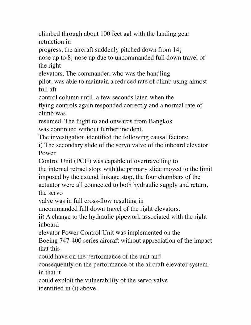
from the consequences and did not contribute to the crash. (18 November 1999)Crash Sequence as mechanical causeDocuments below are from US NTSB and FAA, and Australian, and United Kingdom aviation safety archives.For the 747:Report on the incident to Boeing 747-436, G-BNLY at London HeathrowAirport on 7 October1993SYNOPSISThe flight from London Heathrow to Bangkok took off two minutes behindanother 'Heavy' Boeing 747-400. As the aircraftclimbed through about 100 feet agl with the landing gear retraction inprogress, the aircraft suddenly pitched down from 14¡nose up to 8¡ nose up due to uncommanded full down travel of the rightelevators. The commander, who was the handlingpilot, was able to maintain a reduced rate of climb using almost full aftcontrol column until, a few seconds later, when theflying controls again responded correctly and a normal rate of climb wasresumed. The flight to and onwards from Bangkokwas continued without further incident.The investigation identified the following causal factors:i) The secondary slide of the servo valve of the inboard elevator PowerControl Unit (PCU) was capable of overtravelling tothe internal retract stop; with the primary slide moved to the limitimposed by the extend linkage stop, the four chambers of the
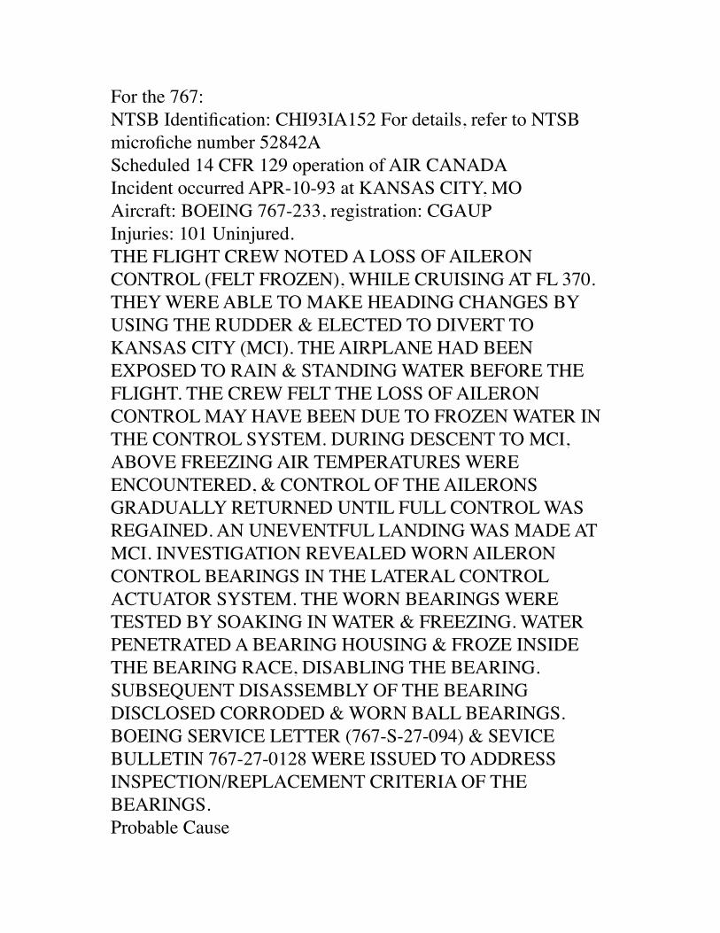
actuator were all connected to both hydraulic supply and return, the servovalve was in full cross-flow resulting inuncommanded full down travel of the right elevators.ii) A change to the hydraulic pipework associated with the right inboardelevator Power Control Unit was implemented on theBoeing 747-400 series aircraft without appreciation of the impact that thiscould have on the performance of the unit andconsequently on the performance of the aircraft elevator system, in that itcould exploit the vulnerability of the servo valveidentified in (i) above.For the 767:NTSB Identification: CHI93IA152 For details, refer to NTSB microfiche number 52842A Scheduled 14 CFR 129 operation of AIR CANADA Incident occurred APR-10-93 at KANSAS CITY, MOAircraft: BOEING 767-233, registration: CGAUP Injuries: 101 Uninjured. THE FLIGHT CREW NOTED A LOSS OF AILERON CONTROL (FELT FROZEN), WHILE CRUISING AT FL 370. THEY WERE ABLE TO MAKE HEADING CHANGES BY USING THE RUDDER & ELECTED TO DIVERT TO KANSAS CITY (MCI). THE AIRPLANE HAD BEEN EXPOSED TO RAIN & STANDING WATER BEFORE THE FLIGHT. THE CREW FELT THE LOSS OF AILERON CONTROL MAY HAVE BEEN DUE TO FROZEN WATER IN THE CONTROL SYSTEM. DURING DESCENT TO MCI, ABOVE FREEZING AIR TEMPERATURES WERE ENCOUNTERED, & CONTROL OF THE AILERONS GRADUALLY RETURNED UNTIL FULL CONTROL WAS
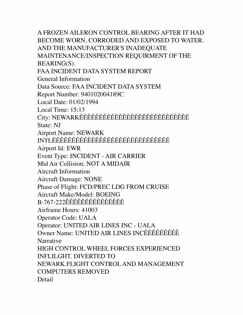
REGAINED. AN UNEVENTFUL LANDING WAS MADE AT MCI. INVESTIGATION REVEALED WORN AILERON CONTROL BEARINGS IN THE LATERAL CONTROL ACTUATOR SYSTEM. THE WORN BEARINGS WERE TESTED BY SOAKING IN WATER & FREEZING. WATER PENETRATED A BEARING HOUSING & FROZE INSIDE THE BEARING RACE, DISABLING THE BEARING. SUBSEQUENT DISASSEMBLY OF THE BEARING DISCLOSED CORRODED & WORN BALL BEARINGS. BOEING SERVICE LETTER (767-S-27-094) & SEVICE BULLETIN 767-27-0128 WERE ISSUED TO ADDRESS INSPECTION/REPLACEMENT CRITERIA OF THE BEARINGS. Probable Cause A FROZEN AILERON CONTROL BEARING AFTER IT HAD BECOME WORN, CORRODED AND EXPOSED TO WATER, AND THE MANUFACTURER'S INADEQUATE MAINTENANCE/INSPECTION REQUIRMENT OF THE BEARING(S).FAA INCIDENT DATA SYSTEM REPORTGeneral InformationData Source: FAA INCIDENT DATA SYSTEMReport Number: 940102004189CLocal Date: 01/02/1994Local Time: 15:13City: NEWARKÊÊÊÊÊÊÊÊÊÊÊÊÊÊÊÊÊÊÊÊÊÊÊÊÊÊÊÊState: NJAirport Name: NEWARK INTLÊÊÊÊÊÊÊÊÊÊÊÊÊÊÊÊÊÊÊÊÊÊÊÊÊÊÊÊÊÊAirport Id: EWREvent Type: INCIDENT - AIR CARRIERMid Air Collision: NOT A MIDAIRAircraft Information
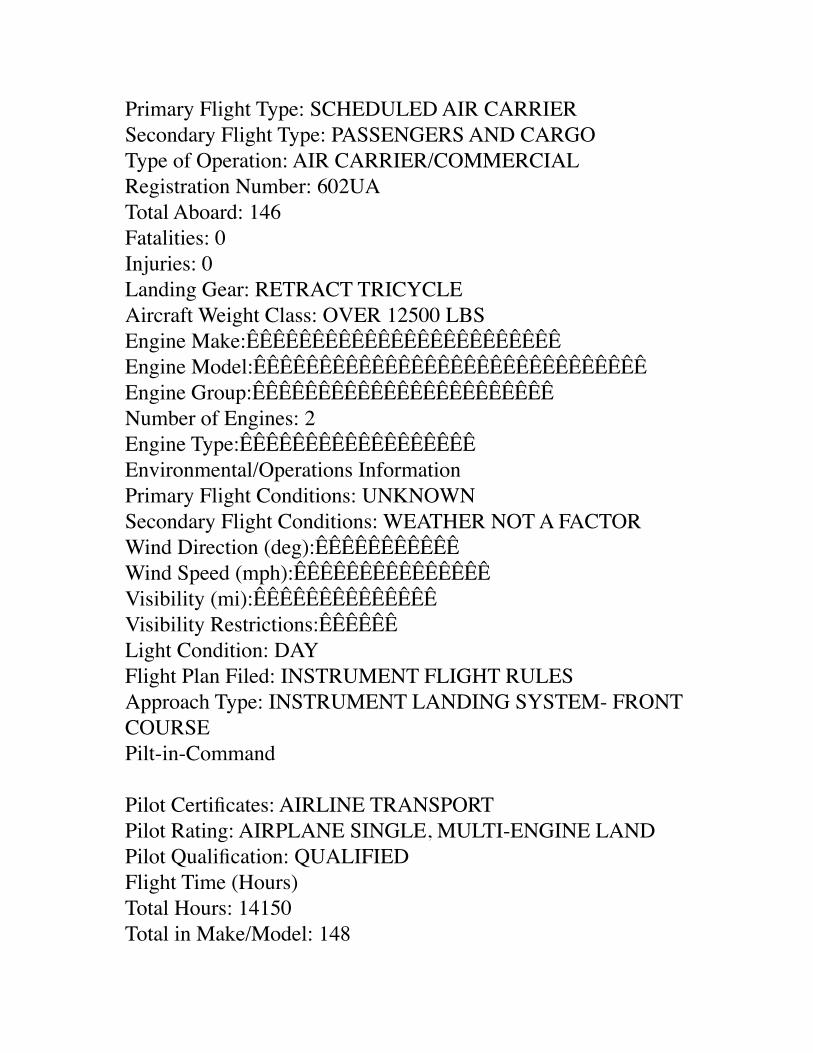
Aircraft Damage: NONEPhase of Flight: FCD/PREC LDG FROM CRUISEAircraft Make/Model: BOEING B-767-222ÊÊÊÊÊÊÊÊÊÊÊÊÊÊÊAirframe Hours: 41003Operator Code: UALAOperator: UNITED AIR LINES INC - UALAOwner Name: UNITED AIR LINES INCÊÊÊÊÊÊÊÊÊNarrativeHIGH CONTROL WHEEL FORCES EXPERIENCED INFLILGHT. DIVERTED TONEWARK.FLIGHT CONTROL AND MANAGEMENT COMPUTERS REMOVEDDetailPrimary Flight Type: SCHEDULED AIR CARRIERSecondary Flight Type: PASSENGERS AND CARGOType of Operation: AIR CARRIER/COMMERCIALRegistration Number: 602UATotal Aboard: 146Fatalities: 0Injuries: 0Landing Gear: RETRACT TRICYCLEAircraft Weight Class: OVER 12500 LBSEngine Make:ÊÊÊÊÊÊÊÊÊÊÊÊÊÊÊÊÊÊÊÊÊÊÊÊEngine Model:ÊÊÊÊÊÊÊÊÊÊÊÊÊÊÊÊÊÊÊÊÊÊÊÊÊÊÊÊÊÊEngine Group:ÊÊÊÊÊÊÊÊÊÊÊÊÊÊÊÊÊÊÊÊÊÊÊNumber of Engines: 2Engine Type:ÊÊÊÊÊÊÊÊÊÊÊÊÊÊÊÊÊÊEnvironmental/Operations InformationPrimary Flight Conditions: UNKNOWNSecondary Flight Conditions: WEATHER NOT A FACTORWind Direction (deg):ÊÊÊÊÊÊÊÊÊÊÊWind Speed (mph):ÊÊÊÊÊÊÊÊÊÊÊÊÊÊÊ
Visibility (mi):ÊÊÊÊÊÊÊÊÊÊÊÊÊÊVisibility Restrictions:ÊÊÊÊÊÊLight Condition: DAYFlight Plan Filed: INSTRUMENT FLIGHT RULESApproach Type: INSTRUMENT LANDING SYSTEM- FRONT COURSEPilt-in-Command
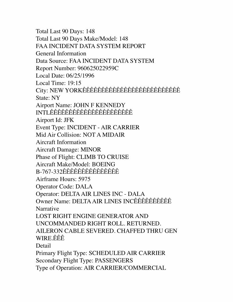
Pilot Certificates: AIRLINE TRANSPORTPilot Rating: AIRPLANE SINGLE, MULTI-ENGINE LANDPilot Qualification: QUALIFIEDFlight Time (Hours)Total Hours: 14150Total in Make/Model: 148Total Last 90 Days: 148Total Last 90 Days Make/Model: 148FAA INCIDENT DATA SYSTEM REPORTGeneral InformationData Source: FAA INCIDENT DATA SYSTEMReport Number: 960625022959CLocal Date: 06/25/1996Local Time: 19:15City: NEW YORKÊÊÊÊÊÊÊÊÊÊÊÊÊÊÊÊÊÊÊÊÊÊÊÊÊÊState: NYAirport Name: JOHN F KENNEDY INTLÊÊÊÊÊÊÊÊÊÊÊÊÊÊÊÊÊÊÊÊÊÊAirport Id: JFKEvent Type: INCIDENT - AIR CARRIERMid Air Collision: NOT A MIDAIRAircraft InformationAircraft Damage: MINORPhase of Flight: CLIMB TO CRUISEAircraft Make/Model: BOEING
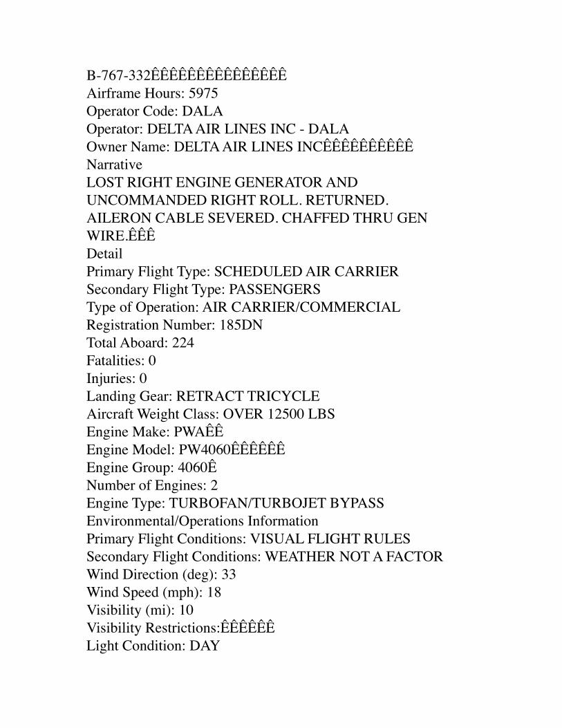
B-767-332ÊÊÊÊÊÊÊÊÊÊÊÊÊÊÊAirframe Hours: 5975Operator Code: DALAOperator: DELTA AIR LINES INC - DALAOwner Name: DELTA AIR LINES INCÊÊÊÊÊÊÊÊÊÊNarrativeLOST RIGHT ENGINE GENERATOR AND UNCOMMANDED RIGHT ROLL. RETURNED.AILERON CABLE SEVERED. CHAFFED THRU GEN WIRE.ÊÊÊDetailPrimary Flight Type: SCHEDULED AIR CARRIERSecondary Flight Type: PASSENGERSType of Operation: AIR CARRIER/COMMERCIALRegistration Number: 185DNTotal Aboard: 224Fatalities: 0Injuries: 0Landing Gear: RETRACT TRICYCLEAircraft Weight Class: OVER 12500 LBSEngine Make: PWAÊÊEngine Model: PW4060ÊÊÊÊÊÊEngine Group: 4060ÊNumber of Engines: 2Engine Type: TURBOFAN/TURBOJET BYPASSEnvironmental/Operations InformationPrimary Flight Conditions: VISUAL FLIGHT RULESSecondary Flight Conditions: WEATHER NOT A FACTORWind Direction (deg): 33Wind Speed (mph): 18Visibility (mi): 10Visibility Restrictions:ÊÊÊÊÊÊLight Condition: DAY
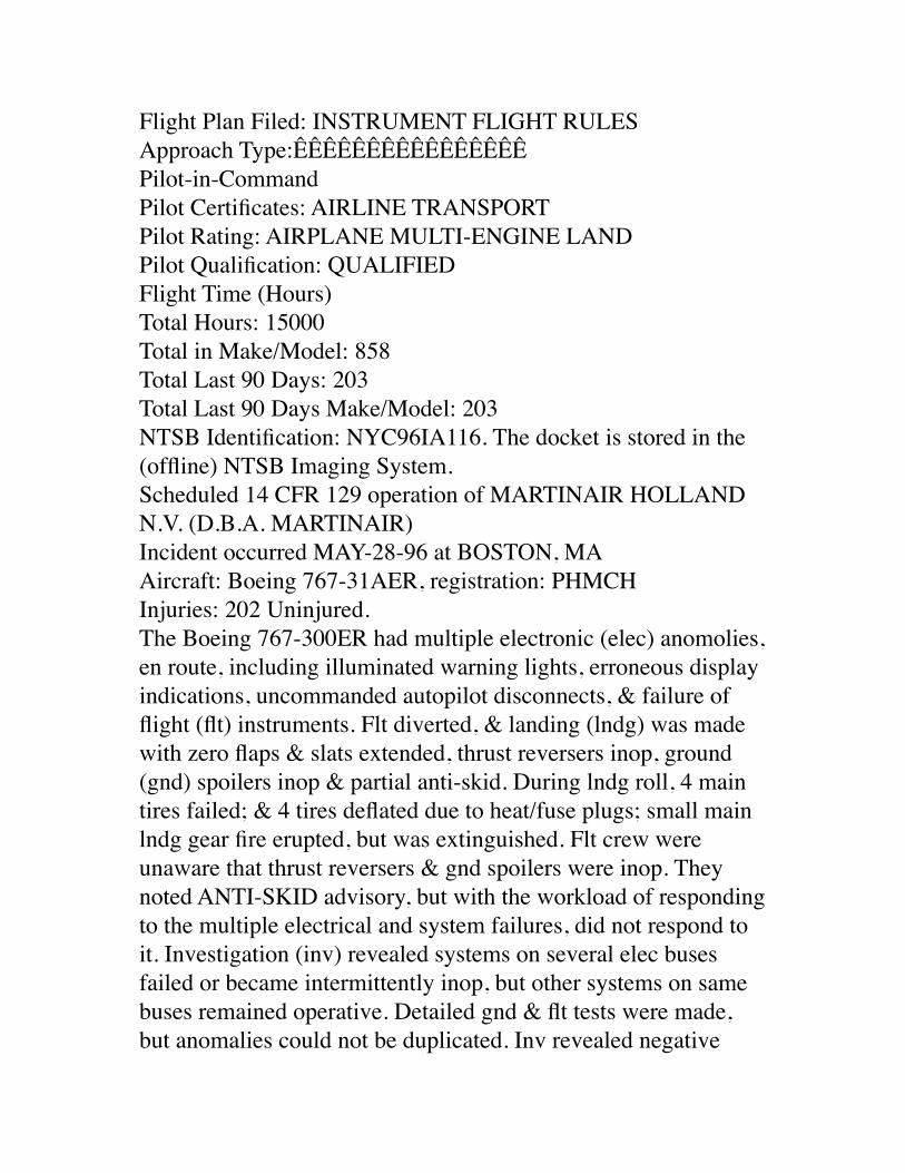
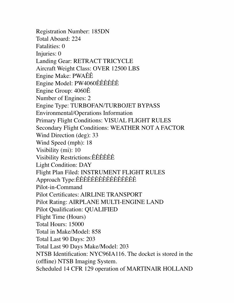
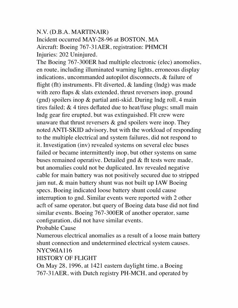
Flight Plan Filed: INSTRUMENT FLIGHT RULESApproach Type:ÊÊÊÊÊÊÊÊÊÊÊÊÊÊÊÊPilot-in-CommandPilot Certificates: AIRLINE TRANSPORTPilot Rating: AIRPLANE MULTI-ENGINE LANDPilot Qualification: QUALIFIEDFlight Time (Hours)Total Hours: 15000Total in Make/Model: 858Total Last 90 Days: 203Total Last 90 Days Make/Model: 203NTSB Identification: NYC96IA116. The docket is stored in the (offline) NTSB Imaging System. Scheduled 14 CFR 129 operation of MARTINAIR HOLLAND N.V. (D.B.A. MARTINAIR) Incident occurred MAY-28-96 at BOSTON, MAAircraft: Boeing 767-31AER, registration: PHMCH Injuries: 202 Uninjured. The Boeing 767-300ER had multiple electronic (elec) anomolies, en route, including illuminated warning lights, erroneous display indications, uncommanded autopilot disconnects, & failure of flight (flt) instruments. Flt diverted, & landing (lndg) was made with zero flaps & slats extended, thrust reversers inop, ground (gnd) spoilers inop & partial anti-skid. During lndg roll, 4 main tires failed; & 4 tires deflated due to heat/fuse plugs; small main lndg gear fire erupted, but was extinguished. Flt crew were unaware that thrust reversers & gnd spoilers were inop. They noted ANTI-SKID advisory, but with the workload of responding to the multiple electrical and system failures, did not respond to it. Investigation (inv) revealed systems on several elec buses failed or became intermittently inop, but other systems on same buses remained operative. Detailed gnd & flt tests were made, but anomalies could not be duplicated. Inv revealed negative
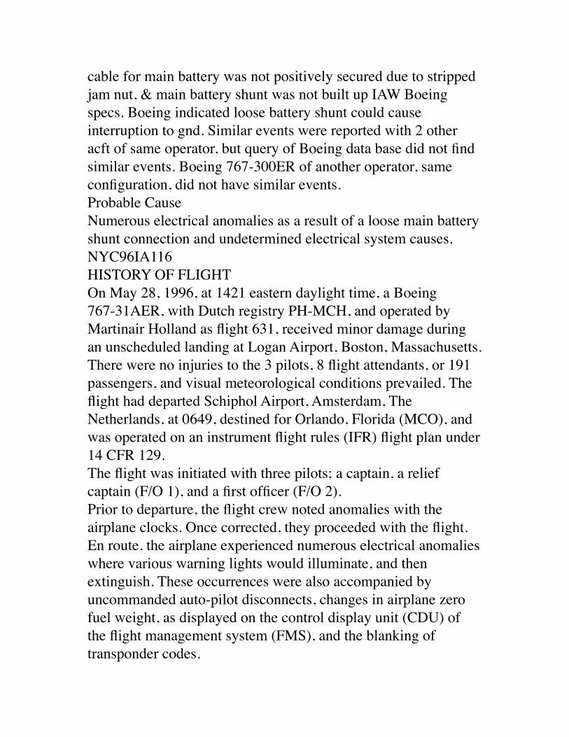
cable for main battery was not positively secured due to stripped jam nut, & main battery shunt was not built up IAW Boeing specs. Boeing indicated loose battery shunt could cause interruption to gnd. Similar events were reported with 2 other acft of same operator, but query of Boeing data base did not find similar events. Boeing 767-300ER of another operator, same configuration, did not have similar events. Probable Cause Numerous electrical anomalies as a result of a loose main battery shunt connection and undetermined electrical system causes. NYC96IA116 HISTORY OF FLIGHT On May 28, 1996, at 1421 eastern daylight time, a Boeing 767-31AER, with Dutch registry PH-MCH, and operated by Martinair Holland as flight 631, received minor damage during an unscheduled landing at Logan Airport, Boston, Massachusetts. There were no injuries to the 3 pilots, 8 flight attendants, or 191 passengers, and visual meteorological conditions prevailed. The flight had departed Schiphol Airport, Amsterdam, The Netherlands, at 0649, destined for Orlando, Florida (MCO), and was operated on an instrument flight rules (IFR) flight plan under 14 CFR 129.The flight was initiated with three pilots; a captain, a relief captain (F/O 1), and a first officer (F/O 2).Prior to departure, the flight crew noted anomalies with the airplane clocks. Once corrected, they proceeded with the flight. En route, the airplane experienced numerous electrical anomalies where various warning lights would illuminate, and then extinguish. These occurrences were also accompanied by uncommanded auto-pilot disconnects, changes in airplane zero fuel weight, as displayed on the control display unit (CDU) of the flight management system (FMS), and the blanking of transponder codes.
The flight crew, in radio contact with their dispatch center, discussed the situation and agreed that they could continue with the flight. The Boeing Aircraft Company through the Martinair dispatch center supplied technical assistance. A check of the passenger cabin revealed that numerous personal electronic devices (PEDs) were in use. They were requested to be turned off. At one time while over the North Atlantic, there was a period of time when no anomalies occurred. Nearing the North American continent, and with additional anomalies occurring, the flight crew initially planned to divert to Newark, New Jersey. As the electrical anomalies continued, additional systems were affected, and a decision was made to divert to Boston, Massachusetts. Following the decision to divert, there were failures of the co-pilots electronic attitude director indictors (EADI), and electronic horizontal situation indicators (EHSI). Navigation was lost to the captain's EHSI.During the initial descent into Boston, the aircraft was flown manually due to autothrottle disengagement and multiple A/P disengagements. When the airplane was configured with flaps 1 (slat extension, no trailing edge flaps), the two needles on a cockpit gauge which represented the respective wing slat positions disagreed. The flight crew checked the runway required for landing with zero flaps, and the runway available at Boston. With sufficient runway available, the captain in concert with the other crew member decided to make no more configuration changes, resulting in a leading edge slat only approach speed of 162 kts, Flap problems had been expected by the crew based on the previous events. The slats were visually inspected to be extended. In the cabin the seatbelts signs switched on and off uncommanded.During the last portion of flight, the Engine Indicating and Crew Alerting System (EICAS) was filled with caution and advisory messages which were read by F/O 2 from the observers seat on
request of the captain. Although no identification could be received from the Instrument Landing System (ILS), the indication on the left Attitude Director Indicator (ADI) and on the standby ADI seemed valid.On final approach to Boston, numerous warning lights illuminated, extinguished, and other warning lights illuminated.After touch down reverse thrust and autospeedbrakes were not available. Manual braking was anticipated since the autobrake selector did not latch. Braking was done manually by the captain while the wing spoilers were extended by the F/O 1. Just after touch-down the captain initially used full manual braking. The cabin crew's observations were as if they were riding on gravel (pebbles), and the cockpit crew suspected tire failures just after turning off the runway. The last high speed turn off to the left was taken to vacate runway 4R, on which the airplane was brought to a stop. The pilots reported to feel no effect from the manually selected ground spoilers. In the meantime all main landing gear tires were blown or deflated and the airplane was brought to a stop without fully vacating the runway.A small wheel brake fire developed after landing and was immediately extinguished by the airport fire fighting personnel.Approximately 25 minutes after landing, the passengers disembarked using mobile stairs.The incident terminated during the hours of daylight at 42 degrees, 21 minutes North latitude and 71 degrees, 00 minutes West longitude. PERSONNEL INFORMATION The flight was conducted using an augmented flight crew, which consisted of two captain rated pilots, and a first officer. All personnel held the appropriate pilot and medical certificates as issued by the government of The Netherlands. Following is a summary of crew flight experience: Captain
The captain had a total time of 6,600 hours, with 3,738 hours in the Boeing 767, including 607 hours as pilot-in-command in the Boeing 767. He had flown 199 hours in the preceding 90 days, including 188 hours in the Boeing 767.Relief Captain (F/O 1) The relief captain had a total time of 4,000 hours, with 1,590 hours in the Boeing 767. He had flown 195 hours in the preceding 90 days, including 190 hours in the Boeing 767.First Officer (F/O 2) The first officer had a total time of 5,180 hours, with 388 hours in the Boeing 767. He had flown 150 hours in the preceding 90 days, all in the Boeing 767.AIRCRAFT INFORMATION The airplane was a Boeing 767- 31AER. The airplane was delivered new to Martinair in February 1990, in Martinair's specified configuration. The Boeing production line number was 194. It was maintained utilizing a maintenance program furnished by Boeing, and approved by the Directorate of Civil Aviation, The Netherlands. The last inspection was conducted on May 21, 1996, and the airplane had operated 98 hours since the inspection. The total time for the airframe at the time of landing at Boston was 30,802 hours.AERODROME INFORMATION The landing was accomplished on runway 4R which was 10,005 feet long, 150 feet wide, and had a grooved asphalt surface. The airplane turned off the runway at taxiway ROMEO, with about 1,800 feet of runway remaining.FLIGHT RECORDERS After the airplane stopped, the cockpit voice recorder operated for over 30 minutes. The cockpit voice recorder was not retained. The digital flight data recorder (DFDR) was retained and forward to the NTSB Laboratory in Washington DC, for readout. According to the Flight Data Recorder (FDR) Specialist's report:
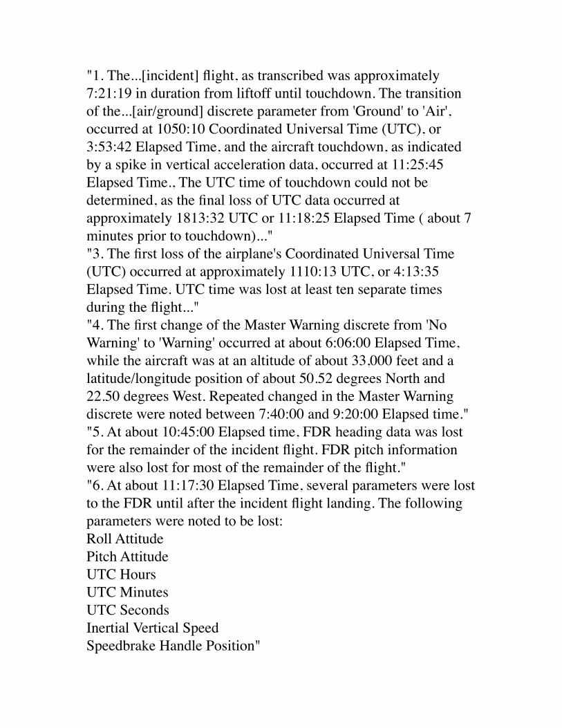
"1. The...[incident] flight, as transcribed was approximately 7:21:19 in duration from liftoff until touchdown. The transition of the...[air/ground] discrete parameter from 'Ground' to 'Air', occurred at 1050:10 Coordinated Universal Time (UTC), or 3:53:42 Elapsed Time, and the aircraft touchdown, as indicated by a spike in vertical acceleration data, occurred at 11:25:45 Elapsed Time., The UTC time of touchdown could not be determined, as the final loss of UTC data occurred at approximately 1813:32 UTC or 11:18:25 Elapsed Time ( about 7 minutes prior to touchdown)...""3. The first loss of the airplane's Coordinated Universal Time (UTC) occurred at approximately 1110:13 UTC, or 4:13:35 Elapsed Time. UTC time was lost at least ten separate times during the flight...""4. The first change of the Master Warning discrete from 'No Warning' to 'Warning' occurred at about 6:06:00 Elapsed Time, while the aircraft was at an altitude of about 33,000 feet and a latitude/longitude position of about 50.52 degrees North and 22.50 degrees West. Repeated changed in the Master Warning discrete were noted between 7:40:00 and 9:20:00 Elapsed time.""5. At about 10:45:00 Elapsed time, FDR heading data was lost for the remainder of the incident flight. FDR pitch information were also lost for most of the remainder of the flight.""6. At about 11:17:30 Elapsed Time, several parameters were lost to the FDR until after the incident flight landing. The following parameters were noted to be lost:Roll Attitude Pitch Attitude UTC Hours UTC Minutes UTC Seconds Inertial Vertical Speed Speedbrake Handle Position"
"7. Also at about 11:17:30 Elapsed Time, the...[air/ground] discrete changed stated from 'Air" to 'Ground', and the Air Driven Pump discrete changed stated from 'Off' to 'On', and the HF/L/R Keying discrete changed state from 'Not Keyed' to 'Keyed'. These discretes remained recorded in these states until after aircraft touchdown. Several additional discretes changed state at about 11:17:30 Elapsed Time, and subsequently changed state after touchdown and during the landing roll-out...."The Addendum to the Flight Data Recorder Factual Report stated:"...The anti-skid fault discrete changed from the 'No Fault' to 'Fault' state at about 1101:00 Elapsed Time. The parameter data remained then the 'Fault' state until after airplane touchdown and rollout, when the recorded data returned to the 'No Fault' state....""According to the airplane manufacturer, if the 28V reference voltage is removed from the FDR during normal flight recording operation, subsequent readout of the FDR will result in...The Air/Ground discrete will always indicate 'Ground'...."TESTS AND RESEARCH The airplane was examined at Boston, from May 29, through June 2, 1996. The four inboard tires had deflated due to melted fuse plugs, and the four outboard tires were deflated due to the casings being worn through. A detailed examination of the airplane was conducted in an attempt to induce the failures that were reported by the flight crew. The testing included the electrical system, shock testing, and engine runs both in the air and ground mode. The testing was unable to duplicate the failures reported by the flight crew.The investigation revealed that the negative cable for the main battery was not positively secured to the main battery shunt as a result of stripped threads found in the jam nut area on the stud. Additionally, the main battery shunt was not built up in accordance with Boeing specifications. An examination of other
Boeing 767s in the Martinair fleet, and on the production line at Boeing revealed similar buildup problems with the battery shunt. Boeing personnel commented that a loose battery shunt may cause interruptions to the ground on the main battery bus of the airplane.While the airplane was in Boston, several of the static wicks were found to have higher resistance than specified. On June 3, 1996, the airplane was ferried to the Boeing plant at Everett, Washington, for additional testing. The flight was conducted on a special flight permit issued by the Federal Aviation Administration (FAA).At Everett, the airplane was subjected to testing equal to or greater than new airplane delivery standards. The wiring system was examined in detail for any anomaly that could have contributed to the problem. An electro magnetic interference (EMI) test was conducted throughout the cockpit and cabin with negative results. Additionally, several components were identified as possible contributors to the event and were removed for separate testing. None of the testing was able to duplicate the events reported by the flight crew.Further testing of the static wicks at Everett found that the airplane could still dissipate static charges within design specification. On June 10th, the airplane was given a flight test. The test flight profile included new airplane delivery standards, and additional testing to determine the source of events on May 28, 1996. The test flight was completed without incident.Following the test flight, as the airplane was prepared for departure to The Netherlands, the right engine integrated drive generator (IDG) failed to come on line. The flight was dispatched with the inoperative IDG, per the airplane minimum equipment list (MEL). The IDG was changed after the airplane arrived in Amsterdam.
The IDG was forwarded to Sunstrand for further examination. According to their report:"...The gold plating on the IDG connector 'A' pins was lower than the engineering print requirements. Evidence of corrosion on the base material of these pins was observed. This conditions could result in an intermittent signal condition from the IDG input speed sensor which could lead to tripping of the IDG from the AC bus."ADDITIONAL DATA/INFORMATION Landing Information Available to Flight CrewThe Martinair quick reference handbook (QRH) contained data for landing with engine inoperative, single and dual hydraulic failures, anti-skid inoperative, wheel brakes inoperative, speed brakes inoperative, and leading edge and trailing edge slat and flap configuration variations. Examination of the QRH revealed the basic computed landing distance would be increased by using the following multiplication factors for inoperative components: Speed Brakes - Auto Inoperative 1.43; No Flap, No Slat Landing 1.45; Anti-Skid Inoperative 2.14. The addition factor for landing with Thrust Reversers Inoperative - Good Braking Action was 30 meters (98.43 feet).During interviews the flight crew acknowledged that they were aware of the ANTI SKID advisory message on the EICAS, but due to high cockpit work load, they did not compute their landing distance with the anti-skid inoperative.Failure of Spoilers to Auto Deploy, and Thrust Reversers to Be OperativeThe flight crew reported that upon touchdown, the spoilers did not automatically deploy, and the thrust reversers were inoperative.The investigation revealed one common system for the spoilers to automatically deploy, and the thrust reversers to be operative,
both air/ground systems must be in the ground mode. According to Boeing, in the flight mode, there are 5 spoilers per wing, with a maximum extension angle of 45 degrees. In the ground mode, there are 6 spoilers per wing, with a maximum extension angle of 60 degrees. Once deployed manually in the air mode, a transition to the ground mode would automatically increase the maximum spoiler angle, and number of spoilers deployed.In the air mode, the thrust reversers were inoperative.According to Boeing, the engines were at flight idle at touchdown, and changed to ground idle about 7 seconds after touchdown. Use of thrust reversers, ground spoilers, and the shift from flight idle to ground idle all required the ground mode signal. According to the flight data recorder, the ground mode signal was recorded as being in the ground mode prior to touchdown, and remained in the ground mode throughout the landing roll. The investigation was unable to determine if the ground mode signal was received by the engines, ground spoilers, and thrust reverser systems after touchdown. National Solar ObservatoryA check with the National Solar Observatory on Kitt Peak, Arizona found no bursts of solar radiation to explain the events of May 28, 1996.Boeing ReportBoeing submitted an event summary based upon the detail summary received from Martinair. The summary of the Boeing report stated:"Most of the reported events from the flight which diverted to Boston on May 28th, 1996, can be attributed to degraded power on the hot battery bus, left dc and right dc buses. Extensive testing and analysis has been unable to explain the degraded dc bus power as was seen on the Martinair airplane.
The existing design will allow for single bus losses with no loss of primary systems and multiple bus loss will still allow safe operation...."Additionally, the investigative team noted that while particular items on a bus had failed, the whole bus never failed, and other items on the same bus remained powered. The investigation was unable to explain the selectivity of inoperative components on a bus.Related EventsThe investigation disclosed that similar events had occurred with two other airplanes in the Martinair 767 fleet. The affected airplanes were PH-MCG, line number 279, delivered new to Martinair on September, 1989, and PH-MCL, line number 415, delivered new to Martinair on February, 1992. According to data received from Boeing, events with elements of a similar nature occurred on the following dates in the aircraft listed, with the May 28, 1996, events in PH-MCH being the most extensive.February 16, 1996PH-MCG March 24, 1996PH-MCHMay 13, 1996PH-MCL May 14, 1996PH-MCG May 28, 1996PH-MCHIncident Under Investigation September 17, 1996PH-MCHA check of modifications completed, engineering changes, and Boeing Service Bulletins and Service Letters was conducted. The only commonality between the three airplanes was a
modification to the forward flight attendant jump seat in compliance with a Boeing service bulletin. Examination of the airplane, which included the electrical wiring behind the modification, failed to find anything that would have contributed to the events reported by the flight crew.At the request of the Safety Board, Boeing conducted a search for similar events within the Boeing 757/767 fleet. The search found nothing similar, other than those events which were observed with PH-MCG and PH-MCL. Boeing also reported that a 767-300 was delivered to another customer in the Martinair configuration. A check with that customer found no history of events similar to the May 28, 1996 event.As part of an agreement to return the airplane to line service, a portable airborne digital data system (PADDS) unit was installed in the airplane to monitor the electrical system. No findings have been generated which would explain the events of May 28, 1996.Summary of Events That OccurredFollowing is a summary of the events as reported by the flight crew that occurred during the flight. - During preflight inspection both the captains and first officer clocks had reset to 00:00. - L IRS DC FAIL, C IRS DC FAIL, & R IRS DC FAIL lights illuminated and then extinguished - occurred multiple times. - APU FUEL VALVE light illuminated and extinguished. - Clocks again display 00:00 several times, EICAS message FLAP/SLAT ELEC appears. - The ZFW changes to the maximum ZFW 130.8 t (288,000 lbs.), the original ZFW was entered again. - The VHF ARINC Communications Addressing and Reporting System (ACARS) system produced and printed the same message six times on the on-board printer, although the airplane was out of range. - When transmitting on the high frequency radio (HF), the EICAS advisory messages FUEL SPAR VAL, R FUEL SPAR VAL, L
IRS DC FAIL, C IRS DC FAIL, R IRS DC FAIL and APU FUEL VAL appeared. The same happened during movement of the electrically powered RH pilot's seat using electrical adjustment control. - HF control during ocean crossing was difficult, for a long time period only Gander, New Foundland, could be contacted. In general when EICAS messages appeared, the related system lights illuminated as well. - The autopilot (A/P) had problems tracking Lateral Navigation (LNAV). The A/P caused the aircraft to start slipping (LH aileron, 8 degree bank, control wheel LH wing down) to track LNAV; the aircraft was trimmed to wings level (with autopilot on, using the rudder trim); later, side slipping to the right occurred, again the aircraft was trimmed. - Electrical current was felt by touching the captain's utility light, while static was experienced from the F/O's electronics flight instruments (EFI) switch. - The auto throttles A/T disconnected once and were reengaged. - In cruise flight many occurrences happened with different aircraft systems. The occurrences seemed to be related with crew actions. An example was the C-A/P disconnected after pushing the ELEC/HYD switch on the maintenance panel ON in order to observe the main battery voltage (28V at that time). - During this time, the A/Ps (C, L and R) disconnected about 50 to 70 times. The frequent A/P disconnects were conformed by the number 2 cabin attendant in the rear cabin who clearly noticed aircraft lateral motion during each A/P disconnect. After each A/P disconnect another A/P was engaged. - The ZFW indication changed to 142.4 t (in excess of the maximum ZFW), the actual ZFW was entered again. - Several times the EICAS messages L IRS DC FAIL, C IRS DC FAIL, R IRS DC FAIL, L FUEL SPAR VAL, R FUEL SPAR VAL and APU FUEL VAL appeared and disappeared. - The A/P caused the aircraft to bank 8 degrees R and L to maintain track (LNAV). After 2 minutes L/R banking, with a maximum track error of 0.1 NM L and R from track, the autoflight mode HDG
SEL was selected on chief pilot's request, being a mode without FMS input. The wind was 330 degrees/variable between 20-29 kts, no DME updates were received. - The ACARS DATA/VOICE transfer switch switched from data to voice and back, every now and then. The related ACARS messages were printed at the Martinair Operations Control Center (OCC). - The selected transponder setting 2430 from Gander changed to 0000 several times (not confirmed by ATC) and was reselected. - The DC voltage on the standby/battery bus (DC-V STBY/BAT) on the EICAS ELEC page dropped to 2 V. The DC current (DC-A) showed 0 and the ECIAS messages APU FUEL VAL, L FUEL SPAR VAL, R FUEL SPAR VAL, L IRS DC FAIL, R IRS DC FAIL, CARGO BTL 1 and CARGO BLT 2 appeared while the A/P again disconnected. - The flap/slats indicator moved to a position halfway between 0 and 1 causing the red overspeed band on the speed-tape to come down and no overspeed warning occurred. the EICAS showed the caution message LE SLAT DISAGREE. Shortly thereafter the flaps/slats indicators returned to 0, the red band moved back to normal and the EICAS message disappeared. - The EICAS caution message "R IRS ON DC" appeared (Right Inertial Reference System on DC power). Only 2 minutes later the EICAS caution message R IRS FAULT appeared (Right Inertial Reference System fault). The IRS INSTRUMENT SOURCE switch was selected to ALTN, each FMC was connected now to its selected IRS only, IRS position averaging was not available. - In the cabin, all emergency lights started to illuminate and remained on. - While the captain was still in contact with Martinair on the left HF radio, this radio failed. New York aeronautical radio inc. (ARINC) was contacted on the C VHF radio to continue the phone-patch with Martinair. Control of the aircraft was transferred to the captain due to an electronic flight information system (EFIS) failure on the F/O's side. The captain completed the VHF contact with Martinair on
the C VHF radio while flying the aircraft manually. Shortly thereafter the navigation data was lost on the captain's HSI. Due to the rapidly deteriorating technical status of the aircraft a PAN call was given to ATC by the PNF. - In order to maintain attitude information, the left IRS was selected to ATT. One crew member reported that this action was accomplished after having observed the EICAS caution messages C IRS ON DC followed by C IRS FAULT and L IRS ON DC followed by L IRS FAULT, indicating a failure of the center and left IRSs. - The aircraft was flown manually on radar vectors, using the standby magnetic compass for headings due to the navigation equipment failure, with no IRS/NAV function, no FMCs, no VORs, no RDMI/VOR and compass functions and no EHSIs were available. Due to the failed FMCs no amber band was available on the speed tape. Around this time one of the right fuel pumps indicated a low output pressure. - Although the right wing fuel tank contained about 1000 kg (2200 lbs) more fuel than the left tank, the aircraft had to be flown with right control wheel inputs to keep the wings level. The crew reported to have no aileron trim available at this stage. ATC was frequently informed about the technical status of the aircraft and a 20 NM line-up was requested while descending to 4000 ft. - During flap extension the flap indicator disagree (one needle between 0 and 1, one needle on 1). The EICAS caution message LE SLAT DISAGREE appeared. - There are two light bulbs in each landing gear indicator. After the landing gear was extended, only one bulb illuminated in each landing gear indicator. Additional PersonsAdditional Persons not listed on page 5 of Factual Report John DeLisiNTSB Aviation Engineering - Systems Tom JackyNTSB Vehicle Performance - Flight Data Recorder
Tamis KwikkersDirectorate General of Civil Aviation - The Netherlands Arthur RiccaFAA - Airworthiness - Boston, MAThe airplane was released to Martinair on June 12, 1996.
FAA INCIDENT DATA SYSTEM REPORTGeneral InformationData Source: FAA INCIDENT DATA SYSTEMReport Number: 930410011849CLocal Date: 04/10/1993Local Time: 12:15City: KANSAS CITY State: MOAirport Name: KANSAS CITY INTL Airport Id: MCIEvent Type: INCIDENT - AIR CARRIERMid Air Collision: NOT A MIDAIRAircraft InformationAircraft Damage: NONEPhase of Flight: FCD/PREC LDG FROM CRUISEAircraft Make/Model: BOEING B-767-200 Airframe Hours: 0Operator Code: ARNFOperator:Owner Name: AIR CANADANarrativeLOST AILERON CONTROL IN FLIGHT.DIVERTED TO KANSAS CITY.LANDED SAFELY.TWAA MAINTENANCE LUBED CENTERING MECHANISM.Detail
Primary Flight Type: SCHEDULED AIR CARRIERSecondary Flight Type: PASSENGERS AND CARGOType of Operation: FOREIGN AIR CARRIERRegistration Number: CGAUPTotal Aboard: 99Fatalities: 0Injuries: 0Landing Gear: RETRACT TRICYCLEAircraft Weight Class: OVER 12500 LBSEngine Make: Engine Model: Engine Group: Number of Engines: 2Engine Type:Environmental/Operations InformationPrimary Flight Conditions: UNKNOWNSecondary Flight Conditions: WEATHER NOT A FACTORWind Direction (deg): Wind Speed (mph): Visibility (mi): Visibility Restrictions: Light Condition: DAYFlight Plan Filed: INSTRUMENT FLIGHT RULESApproach Type:Pilot-in-CommandPilot Certificates: AIRLINE TRANSPORTPilot Rating: Pilot Qualification: UNKNOWN, FOREIGN PILOTFlight Time (Hours)Total Hours: 0Total in Make/Model: 0Total Last 90 Days: 0Total Last 90 Days Make/Model: 0
AAIB Bulletin No: 8/98 Ref: EW/C96/8/5 Category: 1.1INCIDENTAircraft Type and Registration: Boeing 747-236B, G-BDXHNo & Type of Engines: 4 Rolls Royce RB211-524D4 turbofan enginesYear of Manufacture: 1979Date & Time (UTC): 9 August 1996Location: London Airport - GatwickType of Flight: Scheduled PassengerPersons on Board: Crew - N/K - Passengers - N/KInjuries: Crew - Nil - Passengers - NilNature of Damage: Lower rudder hydraulic actuator body fractured, control linkage brokenCommander's Licence: Airline Transport Pilot's LicenceCommander's Age: N/ACommander's Flying Experience: N/AInformation Source: AAIB Field InvestigationÊÊWhilst the aircraft was being taxied out to the runway for take off, the crew carried out the pre-flight checks for full-and-free movement of the controls. During their rudder movement check, the lower section of the rudder jammed at a deflection of 14¡ to the right and, shortly afterwards, a loss of No 2 hydraulic system fluid contents was observed. The aircraft was returned to the terminal gate where initial inspection revealed damage to the lower rudder Power Control Unit (PCU) and its input linkage. The aircraft was taken out of service.The PCU was removed and inspection showed that the casing had cracked circumferentially, near to the ram end, and the crack had extended in an axial direction to the free edge of the casing. This had permitted the externally threaded locking ring, and the power cylinder end seal block which it secured, to move
outwards along the ram towards the eye end. As found, the ram was retracted as far as it was possible with the displaced locking ring and end seal block. The end of the input feedback lever, which attached to the power ram eye end fitting, had broken open. The PCU had been fitted to this aircraft at manufacture and had accumulated approximately 70,500 hours and 12,000 flights.Metallurgical examination revealed that high cycle fatigue had originated in the runout radius of the cylinder thread undercut (see Figures 2a & b) and propagated to a critical length over 3,000 cycles, with evidence of four overload events having occurred within the propagation period. There were no deficiencies in the material specification and no defects were found in the casing which would have contributed to the initiation of the failure. The damage to the end of the input feedback lever had been caused by the actuator ram end retracting into the displaced locking ring and end block. The loss of the hydraulic system fluid was also a result of the displacement of the seal block.There had been two previously recorded cracks in this area of this type of PCU and a fourth occurred shortly after this event. The first event, in 1976, involved an aircraft which had flown 22,000Êhours/6,200Êflight cycles, the second in 1992 on an aircraft which had flown 60,000 hours/15,000 cycles and the most recent in an aircraft which had flown 30,000 cycles, mainly in shorthaul operations.The first of the cylinder casing thread failures occurred on an upper rudder PCU, during a take off; the aircraft suffered the loss of one hydraulic system and the upper rudder jammed at full right deflection. That failure had resulted from fatigue cracking originating in the root of the innermost thread in the casing, which was found to have very sharp radius corners. As a result of this failure, the manufacturer introduced an inspection of the threads at overhaul. In addition, a controlled root radius on the
thread was incorporated into subsequent manufacture, as a product improvement. Later, an increase of the radius in the thread undercut was also introduced as a further product improvement. The need to ensure that the locking ring was properly tightened was also emphasised.The second and fourth failures of this area of the PCU casing both initiated in the thread undercut zone and were similar to the failure on 'XH', but without any overload events.The original design of the PCU was for an aircraft life of 60,000 flight hours/18,000 flight cycles. Endurance testing with an accepted load spectrum was successfully performed on a single PCU and accepted for Type Certification. The overall design philosophy of the rudder system to meet the requirements of FAR/JAR 25.671 resulted in the rudder being made up of two, independently actuated, control surfaces either of which could malfunction within the limits of its actuator's power and authority, in any phase of flight, without loss of adequate rudder control.The design of the PCU incorporated a 'snubbing' action over the last 12% of its stroke (see Figure 2b) which worked by restricting the hydraulic fluid return flow. The purpose of this was to reduce the actuator ram speed as it approached the end of its stroke; the pressure developed in the snubbed volume was greater, the higher the ram speed as the piston entered the snubbing zone. It was considered most likely that the cyclic loads responsible for initiating the fatigue cracking in the thread root and undercut zones had been generated by high snubbing pressures. It was recognised that the situation in which high ram speeds were most likely to be achieved near the limit of travel was during the pre-take-off rudder control check when, in the absence of flight loads, there was no appreciable damping of rudder movement.As a result of the first failure in 1976, the manufacturer had issued an Operations Manual Bulletin and a revision to the
Maintenance Manual, both to the effect that all rudder flight controls checks should be performed slowly and smoothly (not less than 8 seconds for a full cycle) to avoid generating high snubbing loads. Examination of the Flight Recorder data from 'XH' showed that there had been two full travel checks of the rudder during taxy, the first of which was performed in 3.5 seconds and the second in 7.5 seconds. Whilst these last applications of rudder had induced the final failure of the PCU, the crack had then existed for some 3,000 cycles.As a result of this failure on 'XH', the operator instigated a special check of high cycle PCUs; no defects were revealed by these checks. The operator also issued a notice to flight crews, later incorporated into the Flying Manual, reminding crews of the requirement to perform the rudder travel check slowly and smoothly. A programme to monitor rudder application rates at high angles of travel was also introduced and the results of this showed that about 70% of such events occurred during the pre-flight control checks.NTSB Identification: NYC87IA202 For details, refer to NTSB microfiche number 35525AScheduled 14 CFR 121 operation of DELTA AIRLINESÊIncident occurred JUL-12-87 at BOSTON, MAAircraft: BOEING 767-232, registration: N106DAInjuries: 159 Uninjured.DELTA FLT 752, A BOEING 767, WAS NR THE OUTER MARKER (OM) ON AN ILS RWY 22L APCH WHEN THE FLT CONTROL SYS SENSED AN UNCOMMANDED GO-ARND. THE ACFT DRIFTED RGT OF THE LOCALIZER FOR OVR 1 MIN. AT ABT 1000' AGL, RWY 22R WAS SIGHTED TO THE LEFT & A NORMAL LANDING WAS MADE ON THAT RWY. RWY 22R WAS OFFSET 1500' TO THE RGT OF RWY 22L. A BOEING 727, WHICH PRECEDED THE INCIDENT ACFT, WAS CLEARED TO CROSS THE
RGT RWY. THE CONTROLLER FAILED TO OBSERVE THE PROGRESS OF THE BOEING 767 AFTER IT PASSED THE OM. THE BOEING 727 CREW SAW THE BOEING 767 LANDING LIGHTS AS THE ACFT APCHD RWY 22R & NOTIFIED THE TOWER IT WOULD HOLD SHORT OF THE RWY. THE DELTA CAPTAIN HAD A REPUTATION FOR DOMINANT BEHAVIOR WHICH TENDED TO SUPPRESS OTHERS IN THE COCKPIT. THE AIRLINE OPS MANUAL GAVE MINIMAL DIRECTION CONCERNING MISSED APPROACHES. THE UNCOMMANDED GO-AROUND MALFUNCTION WAS TRACED TO A FAULTY WIRING HARNESS IN THE THROTTLE QUADRANT.For the 747:ÊÊ Air Safety Occurrence Report 199701423Ê Occurrence Type: IncidentÊ Location: 5 km N Sydney, AerodromeÊ State: New South WalesÊ Date: Friday, 02 May 1997Ê Time/Zone: 1045 hours EST Ê Investigation Category 3Ê Highest Injury Level: NoneÊ Ê Ê Ê Aircraft Manufacturer: Boeing Co Ê Aircraft Model: 747-300Ê Aircraft Registration: N124KKÊ Serial Number: 23244Ê Type of Operation: Air Transport , High Capacity, InternationalÊ Damage to Aircraft: NilÊ Departure Point: Sydney, NSWÊ Departure Time: 1045 ESTÊ Destination: Seoul, ROKÊ Crew Details: Ê
ÊÊRoleÊPilot-In-CommandClass of Licence Hours on Type Hours TotalATPL 1500.0 20000Ê Ê ÊÊ ContentsFACTUAL INFORMATIONANALYSISSIGNIFICANT FACTORSSAFETY ACTIONLocal safety action ÊÊ FACTUAL INFORMATIONThe aircraft was being operated as a scheduled passenger service from Sydney to Seoul, with the co-pilot as the handling pilot. The crew reported that the pre-departure flight control checks were normal. Shortly after becoming airborne from runway 34L, the co-pilot advised the pilot in command (PIC) that his control wheel had become jammed when attempting to make right wing down aileron inputs. The PIC took control of the aircraft and confirmed that his control wheel also had become jammed. He retained control of the aircraft and the co-pilot advised Air Traffic Services (ATS) that the aircraft was unable to turn to the right. He requested left turns and radar vectors to the south for fuel dumping prior to returning to land. ATS initiated a distress phase. The crew actioned the emergency/abnormal checklist for jammed or restricted flight controls, which includes the statement "use maximum force, including a combined effort by both pilots, if required", but they reported that their attempts made no change to the system. After fuel dumping was completed, the aircraft was vectored, using left turns only, to the runway 34L localiser and configured for the landing. At about 400 ft on final approach, the aileron controls became free and an uneventful landing was carried out.Inspection by ground engineers determined that a plastic cable guard in the left aileron control cable system had broken. Pieces
of shattered plastic were found in the vicinity of the left lower cable pulley system in the vertical cable run behind the cabin sidewall, forward of door 1L. The debris and all the remaining guards were removed from both left and right side vertical cable runs. The lateral control system, including the load limiter system, could not be faulted during full system testing. As there were no replacement cable guards available, the aircraft was approved to return to service with the guards removed.The lateral controls on the aircraft consist of hydraulically powered inboard and outboard ailerons and flight spoilers on each wing. The controls are connected to the cockpit control wheels by cables, for pilot input. The cable runs are duplicated on each side of the aircraft. The left and right cable runs terminate at quadrants at the bases of the left and right control columns respectively. The control columns are interconnected by a cable loop connected to separate quadrants at the bases of the columns. The right quadrant includes a load limiter which consists of a detent and spring loaded cam assembly. The load limiter is designed to "break away" under applied force by the crew to enable one control wheel to provide lateral control input should the other side jam for any reason. Roll control is then available, but considerable force is required to overcome the detent cam in the load limiter. Other Boeing aircraft types utilise similar systems.The aircraft manufacturer issued a Service Letter, 747-SL-27-134, in December 1993, advising that broken cable guards could result in high control wheel forces and suggesting that operators should replace the guards with improved parts when replacement is required. The guards on the right control system on the incident aircraft showed evidence of deterioration, as one guard had been previously repaired with adhesive tape.The aircraft was leased from an overseas operator. Under the terms of the lease agreement, all major maintenance was
conducted by the lessor. The last major maintenance inspection was completed on 25 August 1995. At the time of the incident the aircraft total time in service time was 50,400 hours.The crew remained at the aircraft whilst the defect was rectified. Both crewmembers remarked that they were surprised at the force required to overcome the load limiter when the system was tested. Though they were aware of the load limiting system from ground training instruction, they had never been physically exposed to the forces required to operate the system.ANALYSISThe deteriorated condition of the plastic cable guards, and the use of tape to effect a "repair", suggests that the manufacturer's advice regarding replacement of the guards had not been heeded during major maintenance inspections.It is likely that, when the plastic cable guard failed, a piece or pieces of plastic lodged in the left side cable run aileron control pulley, restricting the cable movement in one direction. The debris probably dislodged when the aircraft was at about 400 ft on final approach.SIGNIFICANT FACTORS1. The aircraft maintenance organisation had not replaced deteriorated parts with improved parts as suggested by the aircraft manufacturer. 2. A cable guard had deteriorated to the extent that it failed and resulted in high control forces in the lateral control system.3. The operating crew were not aware of the high control inputs required to overcome the load limiter in the lateral control system.SAFETY ACTIONAs a result of the investigation, the Bureau of Air Safety Investigation issued recommendation R970128, to Qantas and Ansett on 29 September 1997. The recommendation stated:"The Bureau of Air Safety Investigation recommends that
Australian operators of aircraft manufactured by the Boeing Commercial Airplane Company:1. develop a simulator training procedure to ensure that aircrew are familiar with the procedures to be used in the event of lateral control jamming; and2. ensure that aircrew are aware of the control wheel forces required when the override mechanism is being operated in the event of jammed lateral controls".A similar recommendation (R970145) was issued to the Boeing Commercial Airplane Company on 29 September 1997.The following response was received from Qantas on 26 November 1997:"I refer to your letter reference B97/099 which detailed a recommendation that a simulator training procedure be developed to ensure that all aircrew are aware of the procedure to be used, and control forces required, in the event of aileron control jamming.Qantas simulators (with the exception of the B767-200 simulator) are equipped to simulate aileron control jamming and the control wheel forces required to override and regain control.This scenario will be made a subject, both for discussion and demonstration, in the first available recurrent training simulator session. This will apply to the Boeing 747-400, 747-200/300, 767, 737 and Airbus A300 fleets".Response classification: CLOSED - ACCEPTED.The following response was received from Ansett on 24 June 1998:"I refer to the above recommendation, which resulted from an incident involving a Boeing 747 aircraft at Sydney on 2 May 1997, and provide the following response to that recommendation.The company conducts ground training for technical crews that includes instruction on aileron control jamming procedures.
Additionally, simulator training is presently conducted for Boeing 737 aircraft and will be conducted in the Boeing 767 simulator when that simulator is upgraded to allow such training. For the Boeing 747, training is conducted in the aircraft, whilst on the ground, during type endorsement".Response classification: CLOSED - ACCEPTED.The following response was received from the Boeing Commercial Aeroplane Company on 13 February 1998:"We have not yet committed any changes in our simulator training procedures or manuals. We are reviewing the reported event and looking at possible training and manual changes which would be implemented for all applicable Boeing models, not just 747.However, additional time is necessary for this review before we can come to any conclusion. I anticipate that this review may take three more months. We plan to keep your office advised of the progress of our review".A further response was received on 27 May 1998, and stated:"Earlier this month I reviewed proposed changes to our operational documentation concerning flight control jams accross all our various model airplanes. This has been a slow process trying to get agreement on. I anticipate that we will have some changes to be released in a couple of months. These changes would affect the Flight Manual, the Flight Crew Training Manual, the Operations Manual and the QRH".Response classification: OPEN.Local safety actionBoeing have also advised that Service Letter 747-SL-27-134, which addresses the need to replace deteriorated cable guards, is to be upgraded to service bulletin status in the near future to add more emphasis to this discrepancy.
Ê BASI HomeÊÊ|ÊÊSite IndexÊÊ|ÊÊSearch
Department of Transport and Regional ServicesÊÊÊContact the BASI site editor: [email protected] ÊÊCopyright© Commonwealth of Australia 1999.ÊÊUpdated February 1999.
Contents
From: John Barry Smith <[email protected]>Date: November 22, 1999 9:30:55 AM PSTTo: [email protected]: For Mr. Husseini, EgyptAir 990
Dear Mr. Husseini,Thank you for the discussion in the telephone call, below is my research and tentative analysis.
Cheers,Barry Smith
22 Nov 99
John Barry Smith(831) 659-3552 phone551 Country Club Drive,Carmel Valley, CA [email protected] pilot, instrument rated, former FAA Part 135
certificate holder.US Navy reconnaissance navigator, RA-5C 650 hours.US Navy patrol crewman, P2V-5FS 2000 hours.Air Intelligence Officer, US NavyRetired US Army Major MSCOwner Mooney M-20C, 1000 hours.
Boeing 767(EgyptAir 990)There have been control problems previously in Boeing airliners such as the 737, 747, and 767. The events as described for the aircraft in EgyptAir 990, a 767, would fit an explanation of uncommanded autopilot disconnect and uncommanded down right elevator, two malfunctions that have happened before. Should those two mechanical problems have reappeared, the crew would have then acted valiantly to try to save the aircraft from the consequences and did not contribute to the crash. (18 November 1999)Crash Sequence hypothesis using previous mechanical problems as causes and current evidence to support explanation:Approx 1:49:40 Plane has started to behave oddly because of unusual uncommanded control inputs to right elevator. Pilot utters religious phrase. Religious phrases uttered by devout Muslims is normal under all conditions and normal under a stressful one.1:49:44: Autopilot disconnects. The disconnection is uncommanded but normal when autopilot senses conflicting control inputs. The right down elevator is a conflicting input. The plane continues on but starts flying erratically. Uncommanded autopilot disconnects have happened before in a Boeing 767 on May 28, 1996 on a MartinAir according to NTSB ID NYC96IA116.
1:49:52: Nose down elevator. The malfunction is now right elevator is full down. A Boeing 747, 747-436, G-BNLY, has had uncommanded right elevator full down before on October 7, 1993.1:49:58 The plane starts to dive at 40%. The pilot retards throttles. Engine thrust is reduced but dive continues according to NTSB flight profile: http://www.ntsb.gov/events/ea990/Ea990f~1.jpg1:50:02 Pilot reenters cockpit and asks, "What's going on?" He immediately resumes his left seat and starts pulling back on the yoke to pull plane out of dive, asking his co-pilot, "Help me pull on this," according to cockpit voice recorder statements released by NTSB. Pilot does not say, "Stop that, what are you doing, are you crazy." Pilot does not grab co-pilot to stop him from diving airplane. Pilot does not say, "Put on mask, where is the fire, pull circuit breakers." Pilot treats copilot as assistant to help stop dive.1:50:08: Speed approaches. 86 Mach, alert sounds. Crew continues to pull back on yoke. Plane is in steep dive as left elevator is up and right elevator is full down.1:50:22: Pilot turns engines off and extends speedbrakes to try to stop descent. Crew continues to pull back on yoke.1:50:36: Engines are off, generators are off, plane is dark, uncommanded force is now off right down elevator and it returns to normal and plane bottoms out of its dive and starts to climb bleeding off airspeed from 600 knots at 16300 feet to stall speed at 24000 feet. Crew is unable to restart engines because of G forces and darkness of cockpit. Plane stalls at top of power off climb and descends again to come apart from stress forces at 10000 feet and pieces fall to ocean.The above scenario reflects the facts as released by 19 November 1999. It rules out bomb, or explosive decompression, or fire and smoke in cockpit, or crew incapacitation, or copilot suicide/
murder, or terrorist act, or crew inadvertent error. It does rule in mechanical problems which have happened before to Boeing airliners, uncommanded control inputs resulting in erratic flight characteristics.
Documents from safety Archives:Contents
Boeing 767(EgyptAir 990)There have been control problems previously in Boeing airliners such as the 737, 747, and 767. The events as described for the aircraft in EgyptAir 990, a 767, would fit an explanation of uncommanded autopilot disconnect and uncommanded down right elevator, two malfunctions that have happened before. Should those two mechanical problems have reappeared, the crew would have then acted valiantly to try to save the aircraft from the consequences and did not contribute to the crash. (18 November 1999)Crash Sequence as mechanical causeDocuments below are from US NTSB and FAA, and Australian, and United Kingdom aviation safety archives.For the 747:Report on the incident to Boeing 747-436, G-BNLY at London HeathrowAirport on 7 October1993SYNOPSISThe flight from London Heathrow to Bangkok took off two minutes behindanother 'Heavy' Boeing 747-400. As the aircraft
climbed through about 100 feet agl with the landing gear retraction inprogress, the aircraft suddenly pitched down from 14¡nose up to 8¡ nose up due to uncommanded full down travel of the rightelevators. The commander, who was the handlingpilot, was able to maintain a reduced rate of climb using almost full aftcontrol column until, a few seconds later, when theflying controls again responded correctly and a normal rate of climb wasresumed. The flight to and onwards from Bangkokwas continued without further incident.The investigation identified the following causal factors:i) The secondary slide of the servo valve of the inboard elevator PowerControl Unit (PCU) was capable of overtravelling tothe internal retract stop; with the primary slide moved to the limitimposed by the extend linkage stop, the four chambers of theactuator were all connected to both hydraulic supply and return, the servovalve was in full cross-flow resulting inuncommanded full down travel of the right elevators.ii) A change to the hydraulic pipework associated with the right inboardelevator Power Control Unit was implemented on theBoeing 747-400 series aircraft without appreciation of the impact that thiscould have on the performance of the unit andconsequently on the performance of the aircraft elevator system, in that itcould exploit the vulnerability of the servo valveidentified in (i) above.
For the 767:NTSB Identification: CHI93IA152 For details, refer to NTSB microfiche number 52842A Scheduled 14 CFR 129 operation of AIR CANADA Incident occurred APR-10-93 at KANSAS CITY, MOAircraft: BOEING 767-233, registration: CGAUP Injuries: 101 Uninjured. THE FLIGHT CREW NOTED A LOSS OF AILERON CONTROL (FELT FROZEN), WHILE CRUISING AT FL 370. THEY WERE ABLE TO MAKE HEADING CHANGES BY USING THE RUDDER & ELECTED TO DIVERT TO KANSAS CITY (MCI). THE AIRPLANE HAD BEEN EXPOSED TO RAIN & STANDING WATER BEFORE THE FLIGHT. THE CREW FELT THE LOSS OF AILERON CONTROL MAY HAVE BEEN DUE TO FROZEN WATER IN THE CONTROL SYSTEM. DURING DESCENT TO MCI, ABOVE FREEZING AIR TEMPERATURES WERE ENCOUNTERED, & CONTROL OF THE AILERONS GRADUALLY RETURNED UNTIL FULL CONTROL WAS REGAINED. AN UNEVENTFUL LANDING WAS MADE AT MCI. INVESTIGATION REVEALED WORN AILERON CONTROL BEARINGS IN THE LATERAL CONTROL ACTUATOR SYSTEM. THE WORN BEARINGS WERE TESTED BY SOAKING IN WATER & FREEZING. WATER PENETRATED A BEARING HOUSING & FROZE INSIDE THE BEARING RACE, DISABLING THE BEARING. SUBSEQUENT DISASSEMBLY OF THE BEARING DISCLOSED CORRODED & WORN BALL BEARINGS. BOEING SERVICE LETTER (767-S-27-094) & SEVICE BULLETIN 767-27-0128 WERE ISSUED TO ADDRESS INSPECTION/REPLACEMENT CRITERIA OF THE BEARINGS. Probable Cause
A FROZEN AILERON CONTROL BEARING AFTER IT HAD BECOME WORN, CORRODED AND EXPOSED TO WATER, AND THE MANUFACTURER'S INADEQUATE MAINTENANCE/INSPECTION REQUIRMENT OF THE BEARING(S).FAA INCIDENT DATA SYSTEM REPORTGeneral InformationData Source: FAA INCIDENT DATA SYSTEMReport Number: 940102004189CLocal Date: 01/02/1994Local Time: 15:13City: NEWARKÊÊÊÊÊÊÊÊÊÊÊÊÊÊÊÊÊÊÊÊÊÊÊÊÊÊÊÊState: NJAirport Name: NEWARK INTLÊÊÊÊÊÊÊÊÊÊÊÊÊÊÊÊÊÊÊÊÊÊÊÊÊÊÊÊÊÊAirport Id: EWREvent Type: INCIDENT - AIR CARRIERMid Air Collision: NOT A MIDAIRAircraft InformationAircraft Damage: NONEPhase of Flight: FCD/PREC LDG FROM CRUISEAircraft Make/Model: BOEING B-767-222ÊÊÊÊÊÊÊÊÊÊÊÊÊÊÊAirframe Hours: 41003Operator Code: UALAOperator: UNITED AIR LINES INC - UALAOwner Name: UNITED AIR LINES INCÊÊÊÊÊÊÊÊÊNarrativeHIGH CONTROL WHEEL FORCES EXPERIENCED INFLILGHT. DIVERTED TONEWARK.FLIGHT CONTROL AND MANAGEMENT COMPUTERS REMOVEDDetail
Primary Flight Type: SCHEDULED AIR CARRIERSecondary Flight Type: PASSENGERS AND CARGOType of Operation: AIR CARRIER/COMMERCIALRegistration Number: 602UATotal Aboard: 146Fatalities: 0Injuries: 0Landing Gear: RETRACT TRICYCLEAircraft Weight Class: OVER 12500 LBSEngine Make:ÊÊÊÊÊÊÊÊÊÊÊÊÊÊÊÊÊÊÊÊÊÊÊÊEngine Model:ÊÊÊÊÊÊÊÊÊÊÊÊÊÊÊÊÊÊÊÊÊÊÊÊÊÊÊÊÊÊEngine Group:ÊÊÊÊÊÊÊÊÊÊÊÊÊÊÊÊÊÊÊÊÊÊÊNumber of Engines: 2Engine Type:ÊÊÊÊÊÊÊÊÊÊÊÊÊÊÊÊÊÊEnvironmental/Operations InformationPrimary Flight Conditions: UNKNOWNSecondary Flight Conditions: WEATHER NOT A FACTORWind Direction (deg):ÊÊÊÊÊÊÊÊÊÊÊWind Speed (mph):ÊÊÊÊÊÊÊÊÊÊÊÊÊÊÊVisibility (mi):ÊÊÊÊÊÊÊÊÊÊÊÊÊÊVisibility Restrictions:ÊÊÊÊÊÊLight Condition: DAYFlight Plan Filed: INSTRUMENT FLIGHT RULESApproach Type: INSTRUMENT LANDING SYSTEM- FRONT COURSEPilt-in-Command
Pilot Certificates: AIRLINE TRANSPORTPilot Rating: AIRPLANE SINGLE, MULTI-ENGINE LANDPilot Qualification: QUALIFIEDFlight Time (Hours)Total Hours: 14150Total in Make/Model: 148
Total Last 90 Days: 148Total Last 90 Days Make/Model: 148FAA INCIDENT DATA SYSTEM REPORTGeneral InformationData Source: FAA INCIDENT DATA SYSTEMReport Number: 960625022959CLocal Date: 06/25/1996Local Time: 19:15City: NEW YORKÊÊÊÊÊÊÊÊÊÊÊÊÊÊÊÊÊÊÊÊÊÊÊÊÊÊState: NYAirport Name: JOHN F KENNEDY INTLÊÊÊÊÊÊÊÊÊÊÊÊÊÊÊÊÊÊÊÊÊÊAirport Id: JFKEvent Type: INCIDENT - AIR CARRIERMid Air Collision: NOT A MIDAIRAircraft InformationAircraft Damage: MINORPhase of Flight: CLIMB TO CRUISEAircraft Make/Model: BOEING B-767-332ÊÊÊÊÊÊÊÊÊÊÊÊÊÊÊAirframe Hours: 5975Operator Code: DALAOperator: DELTA AIR LINES INC - DALAOwner Name: DELTA AIR LINES INCÊÊÊÊÊÊÊÊÊÊNarrativeLOST RIGHT ENGINE GENERATOR AND UNCOMMANDED RIGHT ROLL. RETURNED.AILERON CABLE SEVERED. CHAFFED THRU GEN WIRE.ÊÊÊDetailPrimary Flight Type: SCHEDULED AIR CARRIERSecondary Flight Type: PASSENGERSType of Operation: AIR CARRIER/COMMERCIAL
Registration Number: 185DNTotal Aboard: 224Fatalities: 0Injuries: 0Landing Gear: RETRACT TRICYCLEAircraft Weight Class: OVER 12500 LBSEngine Make: PWAÊÊEngine Model: PW4060ÊÊÊÊÊÊEngine Group: 4060ÊNumber of Engines: 2Engine Type: TURBOFAN/TURBOJET BYPASSEnvironmental/Operations InformationPrimary Flight Conditions: VISUAL FLIGHT RULESSecondary Flight Conditions: WEATHER NOT A FACTORWind Direction (deg): 33Wind Speed (mph): 18Visibility (mi): 10Visibility Restrictions:ÊÊÊÊÊÊLight Condition: DAYFlight Plan Filed: INSTRUMENT FLIGHT RULESApproach Type:ÊÊÊÊÊÊÊÊÊÊÊÊÊÊÊÊPilot-in-CommandPilot Certificates: AIRLINE TRANSPORTPilot Rating: AIRPLANE MULTI-ENGINE LANDPilot Qualification: QUALIFIEDFlight Time (Hours)Total Hours: 15000Total in Make/Model: 858Total Last 90 Days: 203Total Last 90 Days Make/Model: 203NTSB Identification: NYC96IA116. The docket is stored in the (offline) NTSB Imaging System. Scheduled 14 CFR 129 operation of MARTINAIR HOLLAND
N.V. (D.B.A. MARTINAIR) Incident occurred MAY-28-96 at BOSTON, MAAircraft: Boeing 767-31AER, registration: PHMCH Injuries: 202 Uninjured. The Boeing 767-300ER had multiple electronic (elec) anomolies, en route, including illuminated warning lights, erroneous display indications, uncommanded autopilot disconnects, & failure of flight (flt) instruments. Flt diverted, & landing (lndg) was made with zero flaps & slats extended, thrust reversers inop, ground (gnd) spoilers inop & partial anti-skid. During lndg roll, 4 main tires failed; & 4 tires deflated due to heat/fuse plugs; small main lndg gear fire erupted, but was extinguished. Flt crew were unaware that thrust reversers & gnd spoilers were inop. They noted ANTI-SKID advisory, but with the workload of responding to the multiple electrical and system failures, did not respond to it. Investigation (inv) revealed systems on several elec buses failed or became intermittently inop, but other systems on same buses remained operative. Detailed gnd & flt tests were made, but anomalies could not be duplicated. Inv revealed negative cable for main battery was not positively secured due to stripped jam nut, & main battery shunt was not built up IAW Boeing specs. Boeing indicated loose battery shunt could cause interruption to gnd. Similar events were reported with 2 other acft of same operator, but query of Boeing data base did not find similar events. Boeing 767-300ER of another operator, same configuration, did not have similar events. Probable Cause Numerous electrical anomalies as a result of a loose main battery shunt connection and undetermined electrical system causes. NYC96IA116 HISTORY OF FLIGHT On May 28, 1996, at 1421 eastern daylight time, a Boeing 767-31AER, with Dutch registry PH-MCH, and operated by
Martinair Holland as flight 631, received minor damage during an unscheduled landing at Logan Airport, Boston, Massachusetts. There were no injuries to the 3 pilots, 8 flight attendants, or 191 passengers, and visual meteorological conditions prevailed. The flight had departed Schiphol Airport, Amsterdam, The Netherlands, at 0649, destined for Orlando, Florida (MCO), and was operated on an instrument flight rules (IFR) flight plan under 14 CFR 129.The flight was initiated with three pilots; a captain, a relief captain (F/O 1), and a first officer (F/O 2).Prior to departure, the flight crew noted anomalies with the airplane clocks. Once corrected, they proceeded with the flight. En route, the airplane experienced numerous electrical anomalies where various warning lights would illuminate, and then extinguish. These occurrences were also accompanied by uncommanded auto-pilot disconnects, changes in airplane zero fuel weight, as displayed on the control display unit (CDU) of the flight management system (FMS), and the blanking of transponder codes.The flight crew, in radio contact with their dispatch center, discussed the situation and agreed that they could continue with the flight. The Boeing Aircraft Company through the Martinair dispatch center supplied technical assistance. A check of the passenger cabin revealed that numerous personal electronic devices (PEDs) were in use. They were requested to be turned off. At one time while over the North Atlantic, there was a period of time when no anomalies occurred. Nearing the North American continent, and with additional anomalies occurring, the flight crew initially planned to divert to Newark, New Jersey. As the electrical anomalies continued, additional systems were affected, and a decision was made to divert to Boston, Massachusetts. Following the decision to divert, there were failures of the co-pilots electronic attitude director indictors
(EADI), and electronic horizontal situation indicators (EHSI). Navigation was lost to the captain's EHSI.During the initial descent into Boston, the aircraft was flown manually due to autothrottle disengagement and multiple A/P disengagements. When the airplane was configured with flaps 1 (slat extension, no trailing edge flaps), the two needles on a cockpit gauge which represented the respective wing slat positions disagreed. The flight crew checked the runway required for landing with zero flaps, and the runway available at Boston. With sufficient runway available, the captain in concert with the other crew member decided to make no more configuration changes, resulting in a leading edge slat only approach speed of 162 kts, Flap problems had been expected by the crew based on the previous events. The slats were visually inspected to be extended. In the cabin the seatbelts signs switched on and off uncommanded.During the last portion of flight, the Engine Indicating and Crew Alerting System (EICAS) was filled with caution and advisory messages which were read by F/O 2 from the observers seat on request of the captain. Although no identification could be received from the Instrument Landing System (ILS), the indication on the left Attitude Director Indicator (ADI) and on the standby ADI seemed valid.On final approach to Boston, numerous warning lights illuminated, extinguished, and other warning lights illuminated.After touch down reverse thrust and autospeedbrakes were not available. Manual braking was anticipated since the autobrake selector did not latch. Braking was done manually by the captain while the wing spoilers were extended by the F/O 1. Just after touch-down the captain initially used full manual braking. The cabin crew's observations were as if they were riding on gravel (pebbles), and the cockpit crew suspected tire failures just after turning off the runway. The last high speed turn off to the left
was taken to vacate runway 4R, on which the airplane was brought to a stop. The pilots reported to feel no effect from the manually selected ground spoilers. In the meantime all main landing gear tires were blown or deflated and the airplane was brought to a stop without fully vacating the runway.A small wheel brake fire developed after landing and was immediately extinguished by the airport fire fighting personnel.Approximately 25 minutes after landing, the passengers disembarked using mobile stairs.The incident terminated during the hours of daylight at 42 degrees, 21 minutes North latitude and 71 degrees, 00 minutes West longitude. PERSONNEL INFORMATION The flight was conducted using an augmented flight crew, which consisted of two captain rated pilots, and a first officer. All personnel held the appropriate pilot and medical certificates as issued by the government of The Netherlands. Following is a summary of crew flight experience: Captain The captain had a total time of 6,600 hours, with 3,738 hours in the Boeing 767, including 607 hours as pilot-in-command in the Boeing 767. He had flown 199 hours in the preceding 90 days, including 188 hours in the Boeing 767.Relief Captain (F/O 1) The relief captain had a total time of 4,000 hours, with 1,590 hours in the Boeing 767. He had flown 195 hours in the preceding 90 days, including 190 hours in the Boeing 767.First Officer (F/O 2) The first officer had a total time of 5,180 hours, with 388 hours in the Boeing 767. He had flown 150 hours in the preceding 90 days, all in the Boeing 767.AIRCRAFT INFORMATION The airplane was a Boeing 767- 31AER. The airplane was
delivered new to Martinair in February 1990, in Martinair's specified configuration. The Boeing production line number was 194. It was maintained utilizing a maintenance program furnished by Boeing, and approved by the Directorate of Civil Aviation, The Netherlands. The last inspection was conducted on May 21, 1996, and the airplane had operated 98 hours since the inspection. The total time for the airframe at the time of landing at Boston was 30,802 hours.AERODROME INFORMATION The landing was accomplished on runway 4R which was 10,005 feet long, 150 feet wide, and had a grooved asphalt surface. The airplane turned off the runway at taxiway ROMEO, with about 1,800 feet of runway remaining.FLIGHT RECORDERS After the airplane stopped, the cockpit voice recorder operated for over 30 minutes. The cockpit voice recorder was not retained. The digital flight data recorder (DFDR) was retained and forward to the NTSB Laboratory in Washington DC, for readout. According to the Flight Data Recorder (FDR) Specialist's report:"1. The...[incident] flight, as transcribed was approximately 7:21:19 in duration from liftoff until touchdown. The transition of the...[air/ground] discrete parameter from 'Ground' to 'Air', occurred at 1050:10 Coordinated Universal Time (UTC), or 3:53:42 Elapsed Time, and the aircraft touchdown, as indicated by a spike in vertical acceleration data, occurred at 11:25:45 Elapsed Time., The UTC time of touchdown could not be determined, as the final loss of UTC data occurred at approximately 1813:32 UTC or 11:18:25 Elapsed Time ( about 7 minutes prior to touchdown)...""3. The first loss of the airplane's Coordinated Universal Time (UTC) occurred at approximately 1110:13 UTC, or 4:13:35 Elapsed Time. UTC time was lost at least ten separate times during the flight..."
"4. The first change of the Master Warning discrete from 'No Warning' to 'Warning' occurred at about 6:06:00 Elapsed Time, while the aircraft was at an altitude of about 33,000 feet and a latitude/longitude position of about 50.52 degrees North and 22.50 degrees West. Repeated changed in the Master Warning discrete were noted between 7:40:00 and 9:20:00 Elapsed time.""5. At about 10:45:00 Elapsed time, FDR heading data was lost for the remainder of the incident flight. FDR pitch information were also lost for most of the remainder of the flight.""6. At about 11:17:30 Elapsed Time, several parameters were lost to the FDR until after the incident flight landing. The following parameters were noted to be lost:Roll Attitude Pitch Attitude UTC Hours UTC Minutes UTC Seconds Inertial Vertical Speed Speedbrake Handle Position""7. Also at about 11:17:30 Elapsed Time, the...[air/ground] discrete changed stated from 'Air" to 'Ground', and the Air Driven Pump discrete changed stated from 'Off' to 'On', and the HF/L/R Keying discrete changed state from 'Not Keyed' to 'Keyed'. These discretes remained recorded in these states until after aircraft touchdown. Several additional discretes changed state at about 11:17:30 Elapsed Time, and subsequently changed state after touchdown and during the landing roll-out...."The Addendum to the Flight Data Recorder Factual Report stated:"...The anti-skid fault discrete changed from the 'No Fault' to 'Fault' state at about 1101:00 Elapsed Time. The parameter data remained then the 'Fault' state until after airplane touchdown and rollout, when the recorded data returned to the 'No Fault' state...."
"According to the airplane manufacturer, if the 28V reference voltage is removed from the FDR during normal flight recording operation, subsequent readout of the FDR will result in...The Air/Ground discrete will always indicate 'Ground'...."TESTS AND RESEARCH The airplane was examined at Boston, from May 29, through June 2, 1996. The four inboard tires had deflated due to melted fuse plugs, and the four outboard tires were deflated due to the casings being worn through. A detailed examination of the airplane was conducted in an attempt to induce the failures that were reported by the flight crew. The testing included the electrical system, shock testing, and engine runs both in the air and ground mode. The testing was unable to duplicate the failures reported by the flight crew.The investigation revealed that the negative cable for the main battery was not positively secured to the main battery shunt as a result of stripped threads found in the jam nut area on the stud. Additionally, the main battery shunt was not built up in accordance with Boeing specifications. An examination of other Boeing 767s in the Martinair fleet, and on the production line at Boeing revealed similar buildup problems with the battery shunt. Boeing personnel commented that a loose battery shunt may cause interruptions to the ground on the main battery bus of the airplane.While the airplane was in Boston, several of the static wicks were found to have higher resistance than specified. On June 3, 1996, the airplane was ferried to the Boeing plant at Everett, Washington, for additional testing. The flight was conducted on a special flight permit issued by the Federal Aviation Administration (FAA).At Everett, the airplane was subjected to testing equal to or greater than new airplane delivery standards. The wiring system was examined in detail for any anomaly that could have
contributed to the problem. An electro magnetic interference (EMI) test was conducted throughout the cockpit and cabin with negative results. Additionally, several components were identified as possible contributors to the event and were removed for separate testing. None of the testing was able to duplicate the events reported by the flight crew.Further testing of the static wicks at Everett found that the airplane could still dissipate static charges within design specification. On June 10th, the airplane was given a flight test. The test flight profile included new airplane delivery standards, and additional testing to determine the source of events on May 28, 1996. The test flight was completed without incident.Following the test flight, as the airplane was prepared for departure to The Netherlands, the right engine integrated drive generator (IDG) failed to come on line. The flight was dispatched with the inoperative IDG, per the airplane minimum equipment list (MEL). The IDG was changed after the airplane arrived in Amsterdam.The IDG was forwarded to Sunstrand for further examination. According to their report:"...The gold plating on the IDG connector 'A' pins was lower than the engineering print requirements. Evidence of corrosion on the base material of these pins was observed. This conditions could result in an intermittent signal condition from the IDG input speed sensor which could lead to tripping of the IDG from the AC bus."ADDITIONAL DATA/INFORMATION Landing Information Available to Flight CrewThe Martinair quick reference handbook (QRH) contained data for landing with engine inoperative, single and dual hydraulic failures, anti-skid inoperative, wheel brakes inoperative, speed brakes inoperative, and leading edge and trailing edge slat and
flap configuration variations. Examination of the QRH revealed the basic computed landing distance would be increased by using the following multiplication factors for inoperative components: Speed Brakes - Auto Inoperative 1.43; No Flap, No Slat Landing 1.45; Anti-Skid Inoperative 2.14. The addition factor for landing with Thrust Reversers Inoperative - Good Braking Action was 30 meters (98.43 feet).During interviews the flight crew acknowledged that they were aware of the ANTI SKID advisory message on the EICAS, but due to high cockpit work load, they did not compute their landing distance with the anti-skid inoperative.Failure of Spoilers to Auto Deploy, and Thrust Reversers to Be OperativeThe flight crew reported that upon touchdown, the spoilers did not automatically deploy, and the thrust reversers were inoperative.The investigation revealed one common system for the spoilers to automatically deploy, and the thrust reversers to be operative, both air/ground systems must be in the ground mode. According to Boeing, in the flight mode, there are 5 spoilers per wing, with a maximum extension angle of 45 degrees. In the ground mode, there are 6 spoilers per wing, with a maximum extension angle of 60 degrees. Once deployed manually in the air mode, a transition to the ground mode would automatically increase the maximum spoiler angle, and number of spoilers deployed.In the air mode, the thrust reversers were inoperative.According to Boeing, the engines were at flight idle at touchdown, and changed to ground idle about 7 seconds after touchdown. Use of thrust reversers, ground spoilers, and the shift from flight idle to ground idle all required the ground mode signal.
According to the flight data recorder, the ground mode signal was recorded as being in the ground mode prior to touchdown, and remained in the ground mode throughout the landing roll. The investigation was unable to determine if the ground mode signal was received by the engines, ground spoilers, and thrust reverser systems after touchdown. National Solar ObservatoryA check with the National Solar Observatory on Kitt Peak, Arizona found no bursts of solar radiation to explain the events of May 28, 1996.Boeing ReportBoeing submitted an event summary based upon the detail summary received from Martinair. The summary of the Boeing report stated:"Most of the reported events from the flight which diverted to Boston on May 28th, 1996, can be attributed to degraded power on the hot battery bus, left dc and right dc buses. Extensive testing and analysis has been unable to explain the degraded dc bus power as was seen on the Martinair airplane.The existing design will allow for single bus losses with no loss of primary systems and multiple bus loss will still allow safe operation...."Additionally, the investigative team noted that while particular items on a bus had failed, the whole bus never failed, and other items on the same bus remained powered. The investigation was unable to explain the selectivity of inoperative components on a bus.Related EventsThe investigation disclosed that similar events had occurred with two other airplanes in the Martinair 767 fleet. The affected airplanes were PH-MCG, line number 279, delivered new to Martinair on September, 1989, and PH-MCL, line number 415, delivered new to Martinair on February, 1992. According to data
received from Boeing, events with elements of a similar nature occurred on the following dates in the aircraft listed, with the May 28, 1996, events in PH-MCH being the most extensive.February 16, 1996PH-MCG March 24, 1996PH-MCHMay 13, 1996PH-MCL May 14, 1996PH-MCG May 28, 1996PH-MCHIncident Under Investigation September 17, 1996PH-MCHA check of modifications completed, engineering changes, and Boeing Service Bulletins and Service Letters was conducted. The only commonality between the three airplanes was a modification to the forward flight attendant jump seat in compliance with a Boeing service bulletin. Examination of the airplane, which included the electrical wiring behind the modification, failed to find anything that would have contributed to the events reported by the flight crew.At the request of the Safety Board, Boeing conducted a search for similar events within the Boeing 757/767 fleet. The search found nothing similar, other than those events which were observed with PH-MCG and PH-MCL. Boeing also reported that a 767-300 was delivered to another customer in the Martinair configuration. A check with that customer found no history of events similar to the May 28, 1996 event.As part of an agreement to return the airplane to line service, a
portable airborne digital data system (PADDS) unit was installed in the airplane to monitor the electrical system. No findings have been generated which would explain the events of May 28, 1996.Summary of Events That OccurredFollowing is a summary of the events as reported by the flight crew that occurred during the flight. - During preflight inspection both the captains and first officer clocks had reset to 00:00. - L IRS DC FAIL, C IRS DC FAIL, & R IRS DC FAIL lights illuminated and then extinguished - occurred multiple times. - APU FUEL VALVE light illuminated and extinguished. - Clocks again display 00:00 several times, EICAS message FLAP/SLAT ELEC appears. - The ZFW changes to the maximum ZFW 130.8 t (288,000 lbs.), the original ZFW was entered again. - The VHF ARINC Communications Addressing and Reporting System (ACARS) system produced and printed the same message six times on the on-board printer, although the airplane was out of range. - When transmitting on the high frequency radio (HF), the EICAS advisory messages FUEL SPAR VAL, R FUEL SPAR VAL, L IRS DC FAIL, C IRS DC FAIL, R IRS DC FAIL and APU FUEL VAL appeared. The same happened during movement of the electrically powered RH pilot's seat using electrical adjustment control. - HF control during ocean crossing was difficult, for a long time period only Gander, New Foundland, could be contacted. In general when EICAS messages appeared, the related system lights illuminated as well. - The autopilot (A/P) had problems tracking Lateral Navigation (LNAV). The A/P caused the aircraft to start slipping (LH aileron, 8 degree bank, control wheel LH wing down) to track LNAV; the aircraft was trimmed to wings level (with autopilot on, using the rudder trim); later, side slipping to the right occurred, again the aircraft was trimmed. - Electrical current was felt by touching the captain's utility light, while static was experienced from the F/O's
electronics flight instruments (EFI) switch. - The auto throttles A/T disconnected once and were reengaged. - In cruise flight many occurrences happened with different aircraft systems. The occurrences seemed to be related with crew actions. An example was the C-A/P disconnected after pushing the ELEC/HYD switch on the maintenance panel ON in order to observe the main battery voltage (28V at that time). - During this time, the A/Ps (C, L and R) disconnected about 50 to 70 times. The frequent A/P disconnects were conformed by the number 2 cabin attendant in the rear cabin who clearly noticed aircraft lateral motion during each A/P disconnect. After each A/P disconnect another A/P was engaged. - The ZFW indication changed to 142.4 t (in excess of the maximum ZFW), the actual ZFW was entered again. - Several times the EICAS messages L IRS DC FAIL, C IRS DC FAIL, R IRS DC FAIL, L FUEL SPAR VAL, R FUEL SPAR VAL and APU FUEL VAL appeared and disappeared. - The A/P caused the aircraft to bank 8 degrees R and L to maintain track (LNAV). After 2 minutes L/R banking, with a maximum track error of 0.1 NM L and R from track, the autoflight mode HDG SEL was selected on chief pilot's request, being a mode without FMS input. The wind was 330 degrees/variable between 20-29 kts, no DME updates were received. - The ACARS DATA/VOICE transfer switch switched from data to voice and back, every now and then. The related ACARS messages were printed at the Martinair Operations Control Center (OCC). - The selected transponder setting 2430 from Gander changed to 0000 several times (not confirmed by ATC) and was reselected. - The DC voltage on the standby/battery bus (DC-V STBY/BAT) on the EICAS ELEC page dropped to 2 V. The DC current (DC-A) showed 0 and the ECIAS messages APU FUEL VAL, L FUEL SPAR VAL, R FUEL SPAR VAL, L IRS DC FAIL, R IRS DC FAIL, CARGO BTL 1 and CARGO BLT 2 appeared while the A/P again disconnected. - The flap/slats indicator moved to a
position halfway between 0 and 1 causing the red overspeed band on the speed-tape to come down and no overspeed warning occurred. the EICAS showed the caution message LE SLAT DISAGREE. Shortly thereafter the flaps/slats indicators returned to 0, the red band moved back to normal and the EICAS message disappeared. - The EICAS caution message "R IRS ON DC" appeared (Right Inertial Reference System on DC power). Only 2 minutes later the EICAS caution message R IRS FAULT appeared (Right Inertial Reference System fault). The IRS INSTRUMENT SOURCE switch was selected to ALTN, each FMC was connected now to its selected IRS only, IRS position averaging was not available. - In the cabin, all emergency lights started to illuminate and remained on. - While the captain was still in contact with Martinair on the left HF radio, this radio failed. New York aeronautical radio inc. (ARINC) was contacted on the C VHF radio to continue the phone-patch with Martinair. Control of the aircraft was transferred to the captain due to an electronic flight information system (EFIS) failure on the F/O's side. The captain completed the VHF contact with Martinair on the C VHF radio while flying the aircraft manually. Shortly thereafter the navigation data was lost on the captain's HSI. Due to the rapidly deteriorating technical status of the aircraft a PAN call was given to ATC by the PNF. - In order to maintain attitude information, the left IRS was selected to ATT. One crew member reported that this action was accomplished after having observed the EICAS caution messages C IRS ON DC followed by C IRS FAULT and L IRS ON DC followed by L IRS FAULT, indicating a failure of the center and left IRSs. - The aircraft was flown manually on radar vectors, using the standby magnetic compass for headings due to the navigation equipment failure, with no IRS/NAV function, no FMCs, no VORs, no RDMI/VOR and compass functions and no EHSIs were available. Due to the failed FMCs no amber band was available on the speed tape.
Around this time one of the right fuel pumps indicated a low output pressure. - Although the right wing fuel tank contained about 1000 kg (2200 lbs) more fuel than the left tank, the aircraft had to be flown with right control wheel inputs to keep the wings level. The crew reported to have no aileron trim available at this stage. ATC was frequently informed about the technical status of the aircraft and a 20 NM line-up was requested while descending to 4000 ft. - During flap extension the flap indicator disagree (one needle between 0 and 1, one needle on 1). The EICAS caution message LE SLAT DISAGREE appeared. - There are two light bulbs in each landing gear indicator. After the landing gear was extended, only one bulb illuminated in each landing gear indicator. Additional PersonsAdditional Persons not listed on page 5 of Factual Report John DeLisiNTSB Aviation Engineering - Systems Tom JackyNTSB Vehicle Performance - Flight Data Recorder Tamis KwikkersDirectorate General of Civil Aviation - The Netherlands Arthur RiccaFAA - Airworthiness - Boston, MAThe airplane was released to Martinair on June 12, 1996.
FAA INCIDENT DATA SYSTEM REPORTGeneral InformationData Source: FAA INCIDENT DATA SYSTEMReport Number: 930410011849CLocal Date: 04/10/1993Local Time: 12:15City: KANSAS CITY
State: MOAirport Name: KANSAS CITY INTL Airport Id: MCIEvent Type: INCIDENT - AIR CARRIERMid Air Collision: NOT A MIDAIRAircraft InformationAircraft Damage: NONEPhase of Flight: FCD/PREC LDG FROM CRUISEAircraft Make/Model: BOEING B-767-200 Airframe Hours: 0Operator Code: ARNFOperator:Owner Name: AIR CANADANarrativeLOST AILERON CONTROL IN FLIGHT.DIVERTED TO KANSAS CITY.LANDED SAFELY.TWAA MAINTENANCE LUBED CENTERING MECHANISM.DetailPrimary Flight Type: SCHEDULED AIR CARRIERSecondary Flight Type: PASSENGERS AND CARGOType of Operation: FOREIGN AIR CARRIERRegistration Number: CGAUPTotal Aboard: 99Fatalities: 0Injuries: 0Landing Gear: RETRACT TRICYCLEAircraft Weight Class: OVER 12500 LBSEngine Make: Engine Model: Engine Group: Number of Engines: 2Engine Type:
Environmental/Operations InformationPrimary Flight Conditions: UNKNOWNSecondary Flight Conditions: WEATHER NOT A FACTORWind Direction (deg): Wind Speed (mph): Visibility (mi): Visibility Restrictions: Light Condition: DAYFlight Plan Filed: INSTRUMENT FLIGHT RULESApproach Type:Pilot-in-CommandPilot Certificates: AIRLINE TRANSPORTPilot Rating: Pilot Qualification: UNKNOWN, FOREIGN PILOTFlight Time (Hours)Total Hours: 0Total in Make/Model: 0Total Last 90 Days: 0Total Last 90 Days Make/Model: 0AAIB Bulletin No: 8/98 Ref: EW/C96/8/5 Category: 1.1INCIDENTAircraft Type and Registration: Boeing 747-236B, G-BDXHNo & Type of Engines: 4 Rolls Royce RB211-524D4 turbofan enginesYear of Manufacture: 1979Date & Time (UTC): 9 August 1996Location: London Airport - GatwickType of Flight: Scheduled PassengerPersons on Board: Crew - N/K - Passengers - N/KInjuries: Crew - Nil - Passengers - NilNature of Damage: Lower rudder hydraulic actuator body fractured, control linkage brokenCommander's Licence: Airline Transport Pilot's Licence
Commander's Age: N/ACommander's Flying Experience: N/AInformation Source: AAIB Field InvestigationÊÊWhilst the aircraft was being taxied out to the runway for take off, the crew carried out the pre-flight checks for full-and-free movement of the controls. During their rudder movement check, the lower section of the rudder jammed at a deflection of 14¡ to the right and, shortly afterwards, a loss of No 2 hydraulic system fluid contents was observed. The aircraft was returned to the terminal gate where initial inspection revealed damage to the lower rudder Power Control Unit (PCU) and its input linkage. The aircraft was taken out of service.The PCU was removed and inspection showed that the casing had cracked circumferentially, near to the ram end, and the crack had extended in an axial direction to the free edge of the casing. This had permitted the externally threaded locking ring, and the power cylinder end seal block which it secured, to move outwards along the ram towards the eye end. As found, the ram was retracted as far as it was possible with the displaced locking ring and end seal block. The end of the input feedback lever, which attached to the power ram eye end fitting, had broken open. The PCU had been fitted to this aircraft at manufacture and had accumulated approximately 70,500 hours and 12,000 flights.Metallurgical examination revealed that high cycle fatigue had originated in the runout radius of the cylinder thread undercut (see Figures 2a & b) and propagated to a critical length over 3,000 cycles, with evidence of four overload events having occurred within the propagation period. There were no deficiencies in the material specification and no defects were found in the casing which would have contributed to the initiation of the failure. The damage to the end of the input
feedback lever had been caused by the actuator ram end retracting into the displaced locking ring and end block. The loss of the hydraulic system fluid was also a result of the displacement of the seal block.There had been two previously recorded cracks in this area of this type of PCU and a fourth occurred shortly after this event. The first event, in 1976, involved an aircraft which had flown 22,000Êhours/6,200Êflight cycles, the second in 1992 on an aircraft which had flown 60,000 hours/15,000 cycles and the most recent in an aircraft which had flown 30,000 cycles, mainly in shorthaul operations.The first of the cylinder casing thread failures occurred on an upper rudder PCU, during a take off; the aircraft suffered the loss of one hydraulic system and the upper rudder jammed at full right deflection. That failure had resulted from fatigue cracking originating in the root of the innermost thread in the casing, which was found to have very sharp radius corners. As a result of this failure, the manufacturer introduced an inspection of the threads at overhaul. In addition, a controlled root radius on the thread was incorporated into subsequent manufacture, as a product improvement. Later, an increase of the radius in the thread undercut was also introduced as a further product improvement. The need to ensure that the locking ring was properly tightened was also emphasised.The second and fourth failures of this area of the PCU casing both initiated in the thread undercut zone and were similar to the failure on 'XH', but without any overload events.The original design of the PCU was for an aircraft life of 60,000 flight hours/18,000 flight cycles. Endurance testing with an accepted load spectrum was successfully performed on a single PCU and accepted for Type Certification. The overall design philosophy of the rudder system to meet the requirements of FAR/JAR 25.671 resulted in the rudder being made up of two,
independently actuated, control surfaces either of which could malfunction within the limits of its actuator's power and authority, in any phase of flight, without loss of adequate rudder control.The design of the PCU incorporated a 'snubbing' action over the last 12% of its stroke (see Figure 2b) which worked by restricting the hydraulic fluid return flow. The purpose of this was to reduce the actuator ram speed as it approached the end of its stroke; the pressure developed in the snubbed volume was greater, the higher the ram speed as the piston entered the snubbing zone. It was considered most likely that the cyclic loads responsible for initiating the fatigue cracking in the thread root and undercut zones had been generated by high snubbing pressures. It was recognised that the situation in which high ram speeds were most likely to be achieved near the limit of travel was during the pre-take-off rudder control check when, in the absence of flight loads, there was no appreciable damping of rudder movement.As a result of the first failure in 1976, the manufacturer had issued an Operations Manual Bulletin and a revision to the Maintenance Manual, both to the effect that all rudder flight controls checks should be performed slowly and smoothly (not less than 8 seconds for a full cycle) to avoid generating high snubbing loads. Examination of the Flight Recorder data from 'XH' showed that there had been two full travel checks of the rudder during taxy, the first of which was performed in 3.5 seconds and the second in 7.5 seconds. Whilst these last applications of rudder had induced the final failure of the PCU, the crack had then existed for some 3,000 cycles.As a result of this failure on 'XH', the operator instigated a special check of high cycle PCUs; no defects were revealed by these checks. The operator also issued a notice to flight crews, later incorporated into the Flying Manual, reminding crews of the requirement to perform the rudder travel check slowly and
smoothly. A programme to monitor rudder application rates at high angles of travel was also introduced and the results of this showed that about 70% of such events occurred during the pre-flight control checks.NTSB Identification: NYC87IA202 For details, refer to NTSB microfiche number 35525AScheduled 14 CFR 121 operation of DELTA AIRLINESÊIncident occurred JUL-12-87 at BOSTON, MAAircraft: BOEING 767-232, registration: N106DAInjuries: 159 Uninjured.DELTA FLT 752, A BOEING 767, WAS NR THE OUTER MARKER (OM) ON AN ILS RWY 22L APCH WHEN THE FLT CONTROL SYS SENSED AN UNCOMMANDED GO-ARND. THE ACFT DRIFTED RGT OF THE LOCALIZER FOR OVR 1 MIN. AT ABT 1000' AGL, RWY 22R WAS SIGHTED TO THE LEFT & A NORMAL LANDING WAS MADE ON THAT RWY. RWY 22R WAS OFFSET 1500' TO THE RGT OF RWY 22L. A BOEING 727, WHICH PRECEDED THE INCIDENT ACFT, WAS CLEARED TO CROSS THE RGT RWY. THE CONTROLLER FAILED TO OBSERVE THE PROGRESS OF THE BOEING 767 AFTER IT PASSED THE OM. THE BOEING 727 CREW SAW THE BOEING 767 LANDING LIGHTS AS THE ACFT APCHD RWY 22R & NOTIFIED THE TOWER IT WOULD HOLD SHORT OF THE RWY. THE DELTA CAPTAIN HAD A REPUTATION FOR DOMINANT BEHAVIOR WHICH TENDED TO SUPPRESS OTHERS IN THE COCKPIT. THE AIRLINE OPS MANUAL GAVE MINIMAL DIRECTION CONCERNING MISSED APPROACHES. THE UNCOMMANDED GO-AROUND MALFUNCTION WAS TRACED TO A FAULTY WIRING HARNESS IN THE THROTTLE QUADRANT.For the 747:Ê
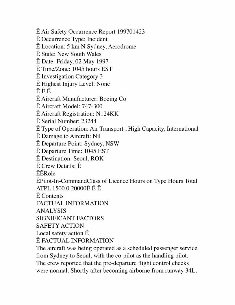
Ê Air Safety Occurrence Report 199701423Ê Occurrence Type: IncidentÊ Location: 5 km N Sydney, AerodromeÊ State: New South WalesÊ Date: Friday, 02 May 1997Ê Time/Zone: 1045 hours EST Ê Investigation Category 3Ê Highest Injury Level: NoneÊ Ê Ê Ê Aircraft Manufacturer: Boeing Co Ê Aircraft Model: 747-300Ê Aircraft Registration: N124KKÊ Serial Number: 23244Ê Type of Operation: Air Transport , High Capacity, InternationalÊ Damage to Aircraft: NilÊ Departure Point: Sydney, NSWÊ Departure Time: 1045 ESTÊ Destination: Seoul, ROKÊ Crew Details: ÊÊÊRoleÊPilot-In-CommandClass of Licence Hours on Type Hours TotalATPL 1500.0 20000Ê Ê ÊÊ ContentsFACTUAL INFORMATIONANALYSISSIGNIFICANT FACTORSSAFETY ACTIONLocal safety action ÊÊ FACTUAL INFORMATIONThe aircraft was being operated as a scheduled passenger service from Sydney to Seoul, with the co-pilot as the handling pilot. The crew reported that the pre-departure flight control checks were normal. Shortly after becoming airborne from runway 34L,
the co-pilot advised the pilot in command (PIC) that his control wheel had become jammed when attempting to make right wing down aileron inputs. The PIC took control of the aircraft and confirmed that his control wheel also had become jammed. He retained control of the aircraft and the co-pilot advised Air Traffic Services (ATS) that the aircraft was unable to turn to the right. He requested left turns and radar vectors to the south for fuel dumping prior to returning to land. ATS initiated a distress phase. The crew actioned the emergency/abnormal checklist for jammed or restricted flight controls, which includes the statement "use maximum force, including a combined effort by both pilots, if required", but they reported that their attempts made no change to the system. After fuel dumping was completed, the aircraft was vectored, using left turns only, to the runway 34L localiser and configured for the landing. At about 400 ft on final approach, the aileron controls became free and an uneventful landing was carried out.Inspection by ground engineers determined that a plastic cable guard in the left aileron control cable system had broken. Pieces of shattered plastic were found in the vicinity of the left lower cable pulley system in the vertical cable run behind the cabin sidewall, forward of door 1L. The debris and all the remaining guards were removed from both left and right side vertical cable runs. The lateral control system, including the load limiter system, could not be faulted during full system testing. As there were no replacement cable guards available, the aircraft was approved to return to service with the guards removed.The lateral controls on the aircraft consist of hydraulically powered inboard and outboard ailerons and flight spoilers on each wing. The controls are connected to the cockpit control wheels by cables, for pilot input. The cable runs are duplicated on each side of the aircraft. The left and right cable runs terminate at quadrants at the bases of the left and right control
columns respectively. The control columns are interconnected by a cable loop connected to separate quadrants at the bases of the columns. The right quadrant includes a load limiter which consists of a detent and spring loaded cam assembly. The load limiter is designed to "break away" under applied force by the crew to enable one control wheel to provide lateral control input should the other side jam for any reason. Roll control is then available, but considerable force is required to overcome the detent cam in the load limiter. Other Boeing aircraft types utilise similar systems.The aircraft manufacturer issued a Service Letter, 747-SL-27-134, in December 1993, advising that broken cable guards could result in high control wheel forces and suggesting that operators should replace the guards with improved parts when replacement is required. The guards on the right control system on the incident aircraft showed evidence of deterioration, as one guard had been previously repaired with adhesive tape.The aircraft was leased from an overseas operator. Under the terms of the lease agreement, all major maintenance was conducted by the lessor. The last major maintenance inspection was completed on 25 August 1995. At the time of the incident the aircraft total time in service time was 50,400 hours.The crew remained at the aircraft whilst the defect was rectified. Both crewmembers remarked that they were surprised at the force required to overcome the load limiter when the system was tested. Though they were aware of the load limiting system from ground training instruction, they had never been physically exposed to the forces required to operate the system.ANALYSISThe deteriorated condition of the plastic cable guards, and the use of tape to effect a "repair", suggests that the manufacturer's advice regarding replacement of the guards had not been heeded during major maintenance inspections.
It is likely that, when the plastic cable guard failed, a piece or pieces of plastic lodged in the left side cable run aileron control pulley, restricting the cable movement in one direction. The debris probably dislodged when the aircraft was at about 400 ft on final approach.SIGNIFICANT FACTORS1. The aircraft maintenance organisation had not replaced deteriorated parts with improved parts as suggested by the aircraft manufacturer. 2. A cable guard had deteriorated to the extent that it failed and resulted in high control forces in the lateral control system.3. The operating crew were not aware of the high control inputs required to overcome the load limiter in the lateral control system.SAFETY ACTIONAs a result of the investigation, the Bureau of Air Safety Investigation issued recommendation R970128, to Qantas and Ansett on 29 September 1997. The recommendation stated:"The Bureau of Air Safety Investigation recommends that Australian operators of aircraft manufactured by the Boeing Commercial Airplane Company:1. develop a simulator training procedure to ensure that aircrew are familiar with the procedures to be used in the event of lateral control jamming; and2. ensure that aircrew are aware of the control wheel forces required when the override mechanism is being operated in the event of jammed lateral controls".A similar recommendation (R970145) was issued to the Boeing Commercial Airplane Company on 29 September 1997.The following response was received from Qantas on 26 November 1997:"I refer to your letter reference B97/099 which detailed a recommendation that a simulator training procedure be
developed to ensure that all aircrew are aware of the procedure to be used, and control forces required, in the event of aileron control jamming.Qantas simulators (with the exception of the B767-200 simulator) are equipped to simulate aileron control jamming and the control wheel forces required to override and regain control.This scenario will be made a subject, both for discussion and demonstration, in the first available recurrent training simulator session. This will apply to the Boeing 747-400, 747-200/300, 767, 737 and Airbus A300 fleets".Response classification: CLOSED - ACCEPTED.The following response was received from Ansett on 24 June 1998:"I refer to the above recommendation, which resulted from an incident involving a Boeing 747 aircraft at Sydney on 2 May 1997, and provide the following response to that recommendation.The company conducts ground training for technical crews that includes instruction on aileron control jamming procedures. Additionally, simulator training is presently conducted for Boeing 737 aircraft and will be conducted in the Boeing 767 simulator when that simulator is upgraded to allow such training. For the Boeing 747, training is conducted in the aircraft, whilst on the ground, during type endorsement".Response classification: CLOSED - ACCEPTED.The following response was received from the Boeing Commercial Aeroplane Company on 13 February 1998:"We have not yet committed any changes in our simulator training procedures or manuals. We are reviewing the reported event and looking at possible training and manual changes which would be implemented for all applicable Boeing models, not just 747.However, additional time is necessary for this review before we
can come to any conclusion. I anticipate that this review may take three more months. We plan to keep your office advised of the progress of our review".A further response was received on 27 May 1998, and stated:"Earlier this month I reviewed proposed changes to our operational documentation concerning flight control jams accross all our various model airplanes. This has been a slow process trying to get agreement on. I anticipate that we will have some changes to be released in a couple of months. These changes would affect the Flight Manual, the Flight Crew Training Manual, the Operations Manual and the QRH".Response classification: OPEN.Local safety actionBoeing have also advised that Service Letter 747-SL-27-134, which addresses the need to replace deteriorated cable guards, is to be upgraded to service bulletin status in the near future to add more emphasis to this discrepancy.
Ê BASI HomeÊÊ|ÊÊSite IndexÊÊ|ÊÊSearchDepartment of Transport and Regional ServicesÊÊÊContact the BASI site editor: [email protected] ÊÊCopyright© Commonwealth of Australia 1999.ÊÊUpdated February 1999.
Contents
From: John Barry Smith <[email protected]>
Date: November 23, 1999 3:43:03 PM PSTTo: [email protected]: For Mr. Husseini, Followup
Dear Mr. Husseini,
I trust the information about uncommanded elevator movement and autopilot disconnects was valuable. Can you assist me in another aviation safety related matter?
Based on government documents and aviation accident reports, I have determined that there is a strong likelihood that Pan Am 103 was not a bomb but an inadvertently opened forward cargo door in flight, probably actuated by faulty wiring. The evidence is so strong that the cause of the tragedy was a mechanical defect and not sabotage by Libyan secret agents that I believe the defense team defending those innocent men should be informed of my research and analysis. Can you help me do that?
I would be willing to discuss my facts, data, and evidence supporting the mechanical cause with any Libyan official that you might be able to refer to me. He could call me or email me.
In summary, evidence from official aviation safety documents leads me to conclude there was no conspiracy to cause the crash of Pan Am 103, but a mechanical defect which has happened before and may happen again; explosive decompression when the forward cargo door inadvertently opens in flight. I would like to present this valuable evidence to the defense team defending those accused and to help cause the faulty wiring in Boeing 747s to be repaired. Much of my evidence is on my web site at www.corazon.com
Mr. Husseini, can you please put them or their representatives in
contact with me?
Cheers,Barry Smith
John Barry Smith(831) 659-3552 phone551 Country Club Drive,Carmel Valley, CA [email protected] Nov 99
From: Pub Inq Web Mailbox <[email protected]>Date: March 30, 2000 1:26:46 PM PSTTo: "'[email protected]'" <[email protected]>Subject: TWA witness information
The information will be mailed to you today on CD ROM.
From: John Barry Smith <[email protected]>Date: November 2, 2000 9:32:08 AM PSTTo: [email protected]: I claim three rewards.
Dear Interagency Rewards Committee:
30 Oct 00
I claim three rewards for identifying the causes of three aircraft accidents, AI 182, TWA 800, and PA 103. The cause is open cargo door in flight and not terrorist bombs or missiles.I have previously claimed the rewards going back to 1996.
I request to be interviewed concerning my claims of reward.
Cheers,John Barry Smith(831) 659-3552 phone551 Country Club Drive,Carmel Valley, CA [email protected] pilot, instrument rated, former FAA Part 135 certificate holder.US Navy reconnaissance navigator, RA-5C 650 hours.US Navy patrol crewman, P2V-5FS 2000 hours.Air Intelligence Officer, US NavyRetired US Army Major MSCOwner Mooney M-20C, 1000 hours.Survivor of sudden night fiery fatal jet plane crash in RA-5CTo: [email protected]: John Barry Smith <[email protected]>Subject: I claim two full rewards.Cc:Bcc:X-Attachments:
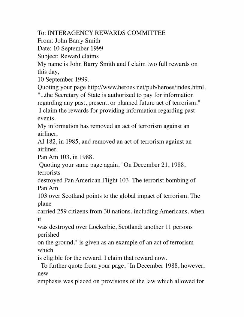
To: INTERAGENCY REWARDS COMMITTEEFrom: John Barry SmithDate: 10 September 1999Subject: Reward claimsMy name is John Barry Smith and I claim two full rewards on this day, 10 September 1999.Quoting your page http://www.heroes.net/pub/heroes/index.html, "...the Secretary of State is authorized to pay for information regarding any past, present, or planned future act of terrorism." I claim the rewards for providing information regarding past events. My information has removed an act of terrorism against an airliner, AI 182, in 1985, and removed an act of terrorism against an airliner, Pan Am 103, in 1988. Quoting your same page again, "On December 21, 1988, terrorists destroyed Pan American Flight 103. The terrorist bombing of Pan Am 103 over Scotland points to the global impact of terrorism. The plane carried 259 citizens from 30 nations, including Americans, when it was destroyed over Lockerbie, Scotland; another 11 persons perished on the ground," is given as an example of an act of terrorism which is eligible for the reward. I claim that reward now. To further quote from your page, "In December 1988, however, new emphasis was placed on provisions of the law which allowed for
payment of rewards in cases where information led to the "prevention, frustration, or favorable resolution of terrorist attacks against United States persons." I claim the two rewards for favorable resolution of terrorists acts regarding the past events, AI 182 and PA 103. My justification for claiming favorable resolution of the two events is that they were not terrorist acts. I have removed the terrorist acts from the causes of AI 182 and PA 103 because the destruction causes of PA 103 and AI 182 were mechanical failures and not terrorist acts. The same mechanical failure of AI 182 and PA 103 was the inadvertent opening of the forward cargo door in flight leading to the destruction of both aircraft. The support and documentation for the claim of mechanical failure and not terrorist acts for AI 182 and PA 103 is on web site, www.corazon.com. Investigation into cargo door cause for other crashes is pending as per requests of Representative Sam Farr, D-CA, 17th district, to the Federal Aviation Agency; and Senator John McCain, R-Ariz. and emails to the FBI at [email protected]. My phone is 408 659 3552, email, [email protected], home address, 551 Country Club Drive, Carmel Valley, CA 93924.
Reference material below:INTERAGENCY REWARDS COMMITTEEThe Director of the Diplomatic Security Service, or his/her
designee, chairs an interagency committee which identifies reward candidates and then recommendsrewards to the Secretary of State. This committee serves as the forum for discussion of many aspects of the Program. The Interagency Rewards Committeeis comprised of representatives from the White House National Security Council staff, the Central Intelligence Agency, the Department of Justice, the FederalBureau of Investigation, the Drug Enforcement Administration, the U.S. Marshals Service Witness Security Program, the Immigration and NaturalizationService, the Federal Aviation Administration, the Department of Energy, and the Department of State. In December 1988, however, new emphasis was placed on provisions of the law which allowed for payment of rewardsin cases where information led to the "prevention, frustration, or favorable resolution of terrorist attacks against United States persons." Specific rewardamounts for particular terrorist incidents were no longer announced. It was instead announced the Secretary of State is authorized to pay for informationregarding any past, present, or planned future act of terrorism.
Subject: I still claim two full rewards againCc:Bcc:X-Attachments:
Dear Committee, 22 Nov 98I reiterate my claim for two full rewards based upon below claim made two years again and repeated regularly.
Cheers,John Barry Smith
To: INTERAGENCY REWARDS COMMITTEEFrom: John Barry SmithDate: 24 November 1996Subject: Reward claimsMy name is John Barry Smith and I claim two full rewards on this day, 24 November 1996.Quoting your page http://www.heroes.net/pub/heroes/index.html, "...the Secretary of State is authorized to pay for information regarding any past, present, or planned future act of terrorism." I claim the rewards for providing information regarding past events. My information has removed an act of terrorism against an airliner, AI 182, in 1985, and removed an act of terrorism against an
airliner, Pan Am 103, in 1988. Quoting your same page again, "On December 21, 1988, terrorists destroyed Pan American Flight 103. The terrorist bombing of Pan Am 103 over Scotland points to the global impact of terrorism. The plane carried 259 citizens from 30 nations, including Americans, when it was destroyed over Lockerbie, Scotland; another 11 persons perished on the ground," is given as an example of an act of terrorism which is eligible for the reward. I claim that reward now. To further quote from your page, "In December 1988, however, new emphasis was placed on provisions of the law which allowed for payment of rewards in cases where information led to the "prevention, frustration, or favorable resolution of terrorist attacks against United States persons." I claim the two rewards for favorable resolution of terrorists acts regarding the past events, AI 182 and PA 103. My justification for claiming favorable resolution of the two events is that they were not terrorist acts. I have removed the terrorist acts from the causes of AI 182 and PA 103 because the destruction causes of PA 103 and AI 182 were mechanical failures and not terrorist acts. The same mechanical failure of AI 182 and PA 103 was the inadvertent opening of the forward cargo door in flight leading to the destruction of both aircraft.
The support and documentation for the claim of mechanical failure and not terrorist acts for AI 182 and PA 103 is on web site, www.corazon.com. Investigation into cargo door cause for other crashes is pending as per requests of Representative Sam Farr, D-CA, 17th district, to the Federal Aviation Agency; and Senator John McCain, R-Ariz. and emails to the FBI at [email protected]. My phone is 408 659 3552, email, [email protected], home address, 551 Country Club Drive, Carmel Valley, CA 93924.
Reference material below:INTERAGENCY REWARDS COMMITTEEThe Director of the Diplomatic Security Service, or his/her designee, chairs an interagency committee which identifies reward candidates and then recommendsrewards to the Secretary of State. This committee serves as the forum for discussion of many aspects of the Program. The Interagency Rewards Committeeis comprised of representatives from the White House National Security Council staff, the Central Intelligence Agency, the Department of Justice, the FederalBureau of Investigation, the Drug Enforcement Administration, the U.S. Marshals Service Witness Security Program, the Immigration and
NaturalizationService, the Federal Aviation Administration, the Department of Energy, and the Department of State. In December 1988, however, new emphasis was placed on provisions of the law which allowed for payment of rewardsin cases where information led to the "prevention, frustration, or favorable resolution of terrorist attacks against United States persons." Specific rewardamounts for particular terrorist incidents were no longer announced. It was instead announced the Secretary of State is authorized to pay for informationregarding any past, present, or planned future act of terrorism.
To: [email protected]: [email protected]: I claim two full rewardsCc:Bcc:X-Attachments:
To: INTERAGENCY REWARDS COMMITTEEFrom: John Barry SmithDate: 16 December 1996Subject: Reward claimsMy name is John Barry Smith and I repeat my claim for two full rewards on this day, 16 Dec 96, First time was 24 November 1996. And again on 23 Jan 1997, Please acknowledge receipt of this email claiming rewards and receipt of previous certified letter and earlier
emails.Quoting your page http://www.heroes.net/pub/heroes/index.html, "...the Secretary of State is authorized to pay for information regarding any past, present, or planned future act of terrorism." I claim the rewards for providing information regarding past events. My information has removed an act of terrorism against an airliner, AI 182, in 1985, and removed an act of terrorism against an airliner, Pan Am 103, in 1988. Quoting your same page again, "On December 21, 1988, terrorists destroyed Pan American Flight 103. The terrorist bombing of Pan Am 103 over Scotland points to the global impact of terrorism. The plane carried 259 citizens from 30 nations, including Americans, when it was destroyed over Lockerbie, Scotland; another 11 persons perished on the ground," is given as an example of an act of terrorism which is eligible for the reward. I claim that reward now. To further quote from your page, "In December 1988, however, new emphasis was placed on provisions of the law which allowed for payment of rewards in cases where information led to the "prevention, frustration, or favorable resolution of terrorist attacks against United States persons." I claim the two rewards for favorable resolution of terrorists acts regarding the past events, AI 182 and PA 103.
My justification for claiming favorable resolution of the two events is that they were not terrorist acts. I have removed the terrorist acts from the causes of AI 182 and PA 103 because the destruction causes of PA 103 and AI 182 were mechanical failures and not terrorist acts. The same mechanical failure of AI 182 and PA 103 was the inadvertent opening of the forward cargo door in flight leading to the destruction of both aircraft. The support and documentation for the claim of mechanical failure and not terrorist acts for AI 182 and PA 103 is on web site, www.corazon.com. Investigation into cargo door cause for other crashes is pending as per requests of Representative Sam Farr, D-CA, 17th district, to the Federal Aviation Agency; and Senator John McCain, R-Ariz. and emails to the FBI at [email protected]. My phone is 408 659 3552, email, [email protected], home address, 551 Country Club Drive, Carmel Valley, CA 93924.
Reference material below:INTERAGENCY REWARDS COMMITTEEThe Director of the Diplomatic Security Service, or his/her designee, chairs an interagency committee which identifies reward candidates and then recommendsrewards to the Secretary of State. This committee serves as the forum
for discussion of many aspects of the Program. The Interagency Rewards Committeeis comprised of representatives from the White House National Security Council staff, the Central Intelligence Agency, the Department of Justice, the FederalBureau of Investigation, the Drug Enforcement Administration, the U.S. Marshals Service Witness Security Program, the Immigration and NaturalizationService, the Federal Aviation Administration, the Department of Energy, and the Department of State. In December 1988, however, new emphasis was placed on provisions of the law which allowed for payment of rewardsin cases where information led to the "prevention, frustration, or favorable resolution of terrorist attacks against United States persons." Specific rewardamounts for particular terrorist incidents were no longer announced. It was instead announced the Secretary of State is authorized to pay for informationregarding any past, present, or planned future act of terrorism.
To: [email protected]: [email protected]: I claim two full rewardsCc:Bcc:X-Attachments:
To: INTERAGENCY REWARDS COMMITTEE
From: John Barry SmithDate: 24 November 1996Subject: Reward claimsMy name is John Barry Smith and I claim two full rewards on this day, 24 November 1996.Quoting your page http://www.heroes.net/pub/heroes/index.html, "...the Secretary of State is authorized to pay for information regarding any past, present, or planned future act of terrorism." I claim the rewards for providing information regarding past events. My information has removed an act of terrorism against an airliner, AI 182, in 1985, and removed an act of terrorism against an airliner, Pan Am 103, in 1988. Quoting your same page again, "On December 21, 1988, terrorists destroyed Pan American Flight 103. The terrorist bombing of Pan Am 103 over Scotland points to the global impact of terrorism. The plane carried 259 citizens from 30 nations, including Americans, when it was destroyed over Lockerbie, Scotland; another 11 persons perished on the ground," is given as an example of an act of terrorism which is eligible for the reward. I claim that reward now. To further quote from your page, "In December 1988, however, new emphasis was placed on provisions of the law which allowed for payment of rewards in cases where information led to the
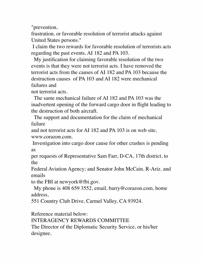
"prevention, frustration, or favorable resolution of terrorist attacks against United States persons." I claim the two rewards for favorable resolution of terrorists acts regarding the past events, AI 182 and PA 103. My justification for claiming favorable resolution of the two events is that they were not terrorist acts. I have removed the terrorist acts from the causes of AI 182 and PA 103 because the destruction causes of PA 103 and AI 182 were mechanical failures and not terrorist acts. The same mechanical failure of AI 182 and PA 103 was the inadvertent opening of the forward cargo door in flight leading to the destruction of both aircraft. The support and documentation for the claim of mechanical failure and not terrorist acts for AI 182 and PA 103 is on web site, www.corazon.com. Investigation into cargo door cause for other crashes is pending as per requests of Representative Sam Farr, D-CA, 17th district, to the Federal Aviation Agency; and Senator John McCain, R-Ariz. and emails to the FBI at [email protected]. My phone is 408 659 3552, email, [email protected], home address, 551 Country Club Drive, Carmel Valley, CA 93924.
Reference material below:INTERAGENCY REWARDS COMMITTEEThe Director of the Diplomatic Security Service, or his/her designee,
chairs an interagency committee which identifies reward candidates and then recommendsrewards to the Secretary of State. This committee serves as the forum for discussion of many aspects of the Program. The Interagency Rewards Committeeis comprised of representatives from the White House National Security Council staff, the Central Intelligence Agency, the Department of Justice, the FederalBureau of Investigation, the Drug Enforcement Administration, the U.S. Marshals Service Witness Security Program, the Immigration and NaturalizationService, the Federal Aviation Administration, the Department of Energy, and the Department of State. In December 1988, however, new emphasis was placed on provisions of the law which allowed for payment of rewardsin cases where information led to the "prevention, frustration, or favorable resolution of terrorist attacks against United States persons." Specific rewardamounts for particular terrorist incidents were no longer announced. It was instead announced the Secretary of State is authorized to pay for informationregarding any past, present, or planned future act of terrorism.
From: Mail Delivery Subsystem <[email protected]>
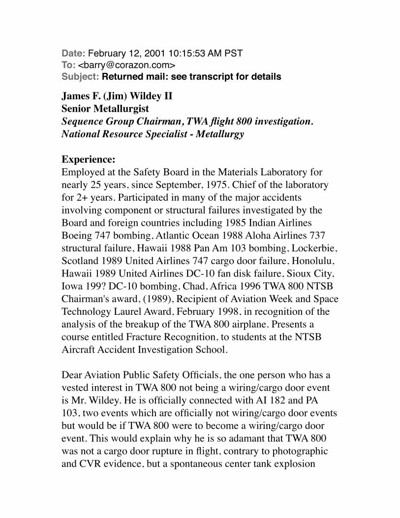
Date: February 12, 2001 10:15:53 AM PSTTo: <[email protected]>Subject: Returned mail: see transcript for details
James F. (Jim) Wildey IISenior MetallurgistSequence Group Chairman, TWA flight 800 investigation.National Resource Specialist - Metallurgy
Experience:Employed at the Safety Board in the Materials Laboratory for nearly 25 years, since September, 1975. Chief of the laboratory for 2+ years. Participated in many of the major accidents involving component or structural failures investigated by the Board and foreign countries including 1985 Indian Airlines Boeing 747 bombing, Atlantic Ocean 1988 Aloha Airlines 737 structural failure, Hawaii 1988 Pan Am 103 bombing, Lockerbie, Scotland 1989 United Airlines 747 cargo door failure, Honolulu, Hawaii 1989 United Airlines DC-10 fan disk failure, Sioux City, Iowa 199? DC-10 bombing, Chad, Africa 1996 TWA 800 NTSB Chairman's award, (1989), Recipient of Aviation Week and Space Technology Laurel Award, February 1998, in recognition of the analysis of the breakup of the TWA 800 airplane. Presents a course entitled Fracture Recognition, to students at the NTSB Aircraft Accident Investigation School.
Dear Aviation Public Safety Officials, the one person who has a vested interest in TWA 800 not being a wiring/cargo door event is Mr. Wildey. He is officially connected with AI 182 and PA 103, two events which are officially not wiring/cargo door events but would be if TWA 800 were to become a wiring/cargo door event. This would explain why he is so adamant that TWA 800 was not a cargo door rupture in flight, contrary to photographic and CVR evidence, but a spontaneous center tank explosion
which lacks the crucial factor of an identified ignition source: He is protecting his opinions of years past, opinions in hindsight which are now suspect, based on matching evidence in the electrical/cargo door UAL 811 accident.
Mr. Wildey's opinions about the destruction sequence and whether the cargo door ruptured in flight are invalid as they are given by an official with a conflict of interest as well as the fact he is not an aircraft accident investigator.
Therefore the entire question of the initial event of TWA 800 and whether the cargo door opened in flight should be renewed by a NTSB aircraft accident investigator who is not connected to AI 182 or PA 103.
Below is a photograph of UAL 811 giving as evidence a similar shape of destruction on the starboard side of TWA 800. The port side of TWA 800 is as smooth as the port side of UAL 811. Both doors had ruptures at the midspan latches. They match in destruction evidence and probable cause, electrical/wiring/cargo door event.
Sincerely,
John Barry Smith(831) 659-3552 phone551 Country Club Drive,Carmel Valley, CA [email protected] pilot, instrument rated, former FAA Part 135
certificate holder.US Navy reconnaissance navigator, RA-5C 650 hours.US Navy patrol crewman, P2V-5FS 2000 hours.Air Intelligence Officer, US NavyRetired US Army Major MSCOwner Mooney M-20C, 1000 hours.Survivor of sudden night fiery fatal jet plane crash in RA-5C
Aging, brittle wiring within aircraft poses a hidden hazard that emerging technologies aim to address
Down to the WireBy Cynthia Furse & Randy Haupt, Utah State University
As today's military and commercial aircraft age past their teen years, the many kilometers of wiring buried deep within their structures begin to crack and fray. Once thought to be rare and
benign, such faults are found by the hundreds in a typical aircraft. Unlike obvious cracks in a wing or an engine, though, damaged wire is extremely difficult to detect. But the resulting
arcing and electromagnetic emissions can be just as deadly: faulty wiring has been blamed for the downing of Swissair 111
near Nova Scotia in 1998 and of TWA 800 off New York's Long Island in 1996 [see http://www.spectrum.ieee.org/WEBONLY/publicfeature/feb01/wiref1.html ]. Indeed, any densely wired system is vulnerable--the space shuttle, nuclear power plants,
subways and railroads, even the family car.
Public scrutiny has prompted strongly worded recommendations from the likes of NASA, the U.S. Federal Aviation
Administration, and the National Transportation Safety Board (NTSB) [see "Government and Industry Take Action" at http://
www.spectrum.ieee.org/WEBONLY/publicfeature/feb01/wiresb1.html ]. "The safety of the nation's wire systems is an
issue of major importance to us all," noted a White House report issued last fall. Several months earlier, the NTSB concluded its
lengthy investigation of TWA 800 with the verdict that a short circuit sparked an explosion in the center wing fuel tank. The
condition of the wiring, it noted, was "not atypical for an airplane of its age." Among the NTSB's recommendations was to
incorporate into aircraft "new technology, such as arc-fault circuit breakers and automated wire test equipment."
Solutions are not straightforward. Among the most promising technologies are advanced reflectometry methods, for routine
maintenance; so-called smart wire systems, for continual, on-the-spot wire testing; and arc-fault circuit breakers and advanced fire
suppression techniques, for minimizing damage and injury should a fault occur. Remaining challenges include detecting the minuscule insulation breaks that encourage arcing; optimizing the benefits and mitigating the risks of the various wire testing
techniques; and getting a better handle on the labyrinthine complexity of aircraft wiring systems.
Failing the test of timeA healthy wire is perhaps the simplest, yet most important,
element in an electrical system. Typically, a copper conductor (from 1 to 10 mm in diameter) is covered by a thin outer
insulation (from 0.5 to 2 mm thick). Damaged insulation can expose the copper, giving rise to arcs, shorts, and
electromagnetic emission and interference. Arcing occurs when current flows from the wire through ionized air to another
conducting object, such as a second wire or the aircraft structure. A short circuit channels the current to an undesired conductor. If
an external shield or braid protecting a wire is broken, the resulting antenna radiates the signal on the wire.
As the wire ages, the insulation may become brittle and crack. Vibration can also chafe the insulation as wires vibrate against each other, a tie-down, or any other hard surface. Maintenance can also be hard on wires, as they may be nicked by workers' pliers, or bent beyond their tolerable radius, or sprinkled with
metal drill shavings, chemicals or water, or even used as stepladders in hard-to-reach places. [see Photos at http://www.spectrum.ieee.org/WEBONLY/publicfeature/feb01/
wiref1.html ] that show cracked and singed wiring taken from U.S. Navy planes.]
But perhaps the greatest concern is the breakdown of the wire's insulation when exposed to moisture. Insulation made from
polyimide film, often referred to by the brand-name Kapton, was once thought to be the ideal wiring insulation and was widely used in both military and commercial aircraft during the 1970s
and early '80s. A long-chain polymer that is both tough and durable, with a very high resistivity, Kapton provides excellent
electrical insulation even at a thickness of less than a millimeter.What was not known initially was how Kapton held up to the
moisture that tends to condense in or near aircraft wiring harnesses. This moisture is so prevalent that most wires are
outfitted with a drip loop, which prevents water droplets from running down the cables and into critical electronics. Exposed to this moisture, Kapton's long polymer chains break down, and the insulation becomes brittle, developing small cracks that in turn
let in even more moisture. So-called wet arcs begin to flow along these cracks, creating intermittent arcs too small to trip normal circuit breakers and often too small even to interfere with the
signal transfer along the wire. Nonetheless, the tiny arcs do begin to carbonize the insulation, and carbon is an excellent conductor. Once enough carbon has built up ("enough" depends on the type and thickness of the insulation, the power handling of the wire, and other factors), there can be a large explosive flashover, with
exposed wires spewing molten metal.
One would hope that Kapton cracks are relatively rare. Not so, according to a recent report by Lectromechanical Design Co., an electrical research firm based in Sterling, Va. Using a proprietary
tool called the DelTest, Letromec engineers tested the wiring in a Boeing 747, an Airbus A300, a Lockheed L-1011, and two
DC-9s that were each over 20 years old and had been retired by commercial airlines within the previous six months. The results:
13 cracks per 1000 meters of wire in the L-1011, down to 1.6 cracks per 1000 meters in one of the DC-9s. With approximately
240 km of wire in the L-1011, this amounted to over 3000 cracks, each a potential cause of catastrophic arcing.
Some time after Kapton's problems came to light, in the late '70s, its use was cut back, and aircraft manufacturers began replacing
it in some of the most critical wiring systems in planes in service. Alternatives to Kapton include polyvinylchloride, glass, nylon,
polyester, and teflon. But polyimide can still be found on thousands of aircraft in service, including the McDonnell
Douglas MD-11 and older Boeing 737s and 767s.How old is too old?
Updating rather than replacing old planes has become a standard way to save money. Some aircraft being designed today, such as the Joint Strike Fighter, may fly 100 years. Similarly, the B-52s
flown by the U.S. Air Force were built in 1961-62 and are expected to remain operational until 2045. Its designers would have never dreamed that this plane would fly for over 80 years. Indeed, not much thought was given to replacing or inspecting the wiring, because the planes were to have been retired long
before any problems developed.So when is it time to scrap an airplane because its wires are too old? The answer depends on a complex array of factors--among them calendar age, manufacturing variations, exposure to water, ultraviolet light, temperature, vibration and g-forces, and stress
during normal use and maintenance.Planes over 20 years old are virtually guaranteed to have wiring problems, many of which turn up during routine maintenance.
The average age of civilian aircraft in use today is 18 years, and
the average age of military planes is 16 years. [See table at http://www.spectrum.ieee.org/WEBONLY/publicfeature/feb01/
wiret1.html ] Of course, most fleets are composed of a mix of aircraft types and ages. Trying to relate this information to wiring
failure probability rates, such as those in the table at http://www.spectrum.ieee.org/WEBONLY/publicfeature/feb01/
wiret2.html , gives some idea why wiring problems are endemic today.
Short of replacing an entire aircraft, how about replacing just the wiring system? That also turns out to be hugely expensive--
anywhere from US $1 million to $5 million for a typical aircraft. Determining what, when, or whether to replace then means
weighing cost against risk--a decision complicated by the fact that neither the cost nor the risk has yet been fully characterized.
What is more, military planes get exposed to more hostile environments than the average commercial plane, so
extrapolation to other types of planes is not necessarily accurate.The maintenance nightmare
Snaking through an aircraft are many kilometers of wire--some 17.5 km in a Navy F-18C/D fighter, 240 km in a typical wide-
body jet. The wire is literally built into the aircraft, running through fuel tanks, and twisted around hydraulic lines. Just
reaching the wiring harness often entails dismantling an aircraft's external structure. And merely touching a wire, let alone
disconnecting, handling, and reconnecting it, heightens the risk that the wire will be damaged.
But maintenance workers do not always show due respect. They have been known to stand on wires instead of step stools, to cut and splice them poorly to get them out of the way of difficult-to-reach places, and to smack connectors with hammers to loosen
them. Tiny razor-sharp metal shavings from maintenance or upgrades, coupled with ordinary aircraft vibration, create the
perfect conditions for insulation damage.
Other parts of the aircraft never get touched, but are no less problematic. The dust bunnies and chaff that collect in these out-of-sight areas are excellent tinder to turn sparks into smoke and
flames. Then there's the sticky "syrup" that collects in and around wire bundles. This well-aged potion of condensation, toilet and
galley leaks, dust, hydraulic fluid, and various unnamable ingredients is intensely caustic to most kinds of insulation. One of the Navy and FAA directives for making aging wiring safer
has been simply to improve cleanliness within aircraft!Compounding the maintenance nightmare is its high cost. By one estimate, the Navy spends 1.8 million person-hours each year to
troubleshoot and repair its aircraft wiring systems.Why state of the art isn't enough
Wire troubleshooting is still very much a hands-on art that has changed little over the last 40 years. Among the techniques in
current use are visual inspection, several versions of reflectometry, and impedance testing. Each technique has its
advantages and, more importantly, disadvantages.Visual inspection is still the most common way to check for
wiring failures. It entails accessing the cables and then carefully checking the insulation for holes and cracks, often no larger than the head of a pin. Whole sections of wiring never get inspected: chafed insulation can be hidden under clamps or around corners, or within multiwire bundles, each consisting of 75 or more wires.
And many wire bundles are built right into the walls of the aircraft.
Another approach involves measuring the cable's resistance from end to end. A low resistance means the cable is "good," and a
high resistance means that it is broken. When a very high voltage (500 V or more) is placed between adjacent, supposedly
unconnected wires, current leakage from one wire to another can indicate degraded insulation.
There is some concern, though, that high voltage may in itself damage the insulation. So nondestructive resistance tests, such as those developed by Eclypse International Corp., Corona, Calif., use voltages of 28 V or less. A floating comparator analyzes the
currents on the cable as the input current is stepped through several levels. In a healthy cable, Ohm's Law predicts that the
resistance will stay the same for all current levels. If it does not, then something is wrong with the cable. The method has been
used to locate cold solder joints, bad crimps, carbonization of the cable or connectors, and foreign matter on or near the cables. And unlike the high-voltage tests, it can be used on a fueled
airplane. It does, though, still require disconnecting and reconnecting the cables.
Several techniques now used or under development involve reflectometry. Common to all these methods is the sending of a
signal (a pulse, sine wave, or the like) down the wire and sensing the reflection that returns from the wire's end. They are most
useful for detecting so-called hard errors, such as short circuits, but have not proven useful for less obvious wire problems.
Time domain reflectometry (TDR) is customarily used when a wiring problem is already suspected. A short, typically rectangular pulse is sent down the cable, and the cable
impedance, termination, and length give a unique temporal signature to the reflected signal. A trained technician then
interprets the signature to determine the health of the cable. Such signal interpretation is particularly necessary for aircraft systems,
where wires branch into complicated network structures and connect to active avionics. The running joke about TDR is that it
requires a Ph.D. to use.Standing-wave reflectometry (SWR) involves sending a
sinusoidal waveform down the wire. A reflected sinusoid is returned from the wire's end, and the two signals add to a
standing wave on the line. The peaks and nulls of this standing
wave give information on the length and terminating load of the cable; a healthy line's wave pattern will be distinct from that of a line with an open or short circuit. The edge this method has over
TDR is that the electronics are simpler and therefore less expensive.
Like SWR, frequency domain reflectometry (FDR) uses sine waves. FDR, though, directly measures the phase difference
between the incident and reflected waves; any faults in the line will generate resonances between the two signals. This method is
being developed for in situ wire testing by researchers at Utah State University with support from Management Sciences Inc., Albuquerque, N.M., and the Naval Air Systems Command. The
goal is to allow preflight testing of cables with the touch of a button, and without the risk of damaging the cables by
disconnecting them.On the horizon
Because of the shortcomings in the above techniques, researchers are now looking at several new technologies. These include
automated reflectometry testing; smart wire systems for real-time, on-the-spot testing; and, in the event of an in-flight failure, advanced fire suppression methods and arc-fault circuit breakers.Automating the reflectometry methods now in use may one day mean that maintenance workers will be able to gauge a cable's
health with minimal physical intervention. A hand-held unit would clamp around the wire, rather than directly connecting to
it. Recently, a fully automated TDR unit was developed by Phoenix Aviation and Technology. It provides a wider range of
fault diagnostics and prognostics, with precise location and interpretation of the fault. The same software can be easily
embedded into application-specific IC format or similar small computing platforms, thus paving the way for real-time
embedded conductor monitoring.
All the same, reflectometry is pushing the state of the art when it comes to finding small insulation cracks, detecting chafed
insulation before arcs occur, and locating an arc's source. Better detection of these tiny anomalies may be achievable by wetting the cable with water or saline solution, or filling the plane with
inert gas.Perhaps the maintenance worker's greatest nightmare is finding
faults that come and go. These so-called ticking faults arise from vibration, temperature change, moisture, g-forces,
electromagnetic interference, and so on. Diagnosing the problem requires systems that can function in flight, where ticking faults
usually occur.Smart wire systems are thus being designed for testing cables continuously, both before takeoff and during a flight. Systems
now under development include a frequency domain reflectometer, on-board processor, environmental sensors, and
wireless communication system integrated into a single miniaturized unit, hundreds of which can be embedded in the wiring system. They will monitor the health of the cable and
guide cable maintenance, and even detect any faults that occur and correct them in real time.
For the aircraft being designed today, a novel kind of wiring with a complete array of embedded sensors is being proposed. This is particularly critical for long-lived planes such as the Joint Strike
Fighter. Weight and space constraints are likely to drive this technology to nanoscale sensors, emerging material science technologies, and microelectromechanical system devices.
Of course, wire failures will still occur. New technologies that can help limit the damage in such an event include arc-fault
circuit breakers and fire suppression methods.------------------------------------------------------------------------------
--Smart wire systems will continuously monitor the cable's
health and correct faults as they occur------------------------------------------------------------------------------
--Ordinary circuit breakers are heat-sensitive bimetal elements that
trip only when a large current passes through the circuit long enough to heat the element. This power may be on the order of
1000 percent of the rated current for 0.35 to 0.8 seconds. By comparison, a single arc fault may last only 1.25 ms, and a series
of events may last 20-30 ms. Too fleeting to trip the circuit breaker, these arc faults can nonetheless cause catastrophic local damage to the wire. Fires have been known to break out with the
breaker still intact.Arc-fault circuit breakers contain sophisticated electronics to
sample the current on the wire at submillisecond intervals. Both time and frequency domain filtering are used to extract the arc-
fault signature from the current waveform. This signature may be integrated over time to discriminate, by means of pattern-
matching algorithms, between a normal current and a sputtering arc-fault current. And so ordinary transients, due to, say, a motor being turned on and off, can be distinguished from the random
current surges that occur with arcing.
Arc-fault breakers are already required in new home wiring in the United States and are now being miniaturized for use on
aircraft. Normally these breakers either are used in tandem with a traditional heat-sensitive breaker or else include a heat-sensitive element in addition to the pattern-matching electronics. Ideally, circuitry will also be added to locate the fault after the breaker
has tripped.Once a fire starts on an aircraft, it spreads rapidly, aided by
Mylar-backed insulation in the cabin walls, limited access to fire extinguishers, and so on. New extinguisher designs that rely on super-fine, high-pressure mists of water, inert gases, and other
techniques are now being developed to put out all types of aircraft fires, including those due to faulty wiring.
Amazingly little is known about how and why wires age, but polymer scientists are making up for lost time. Among other
things, they are studying the chemical and physical changes and resultant effects on electrical insulation properties that occur as wires age. One goal is to find new materials to replace copper
wiring in signal-transfer and electromagnetic interference shielding on aircraft, as well as new types of wire insulation that
resist chafing and have extended life and built-in diagnostics.Not to panic
If you happen to read this article while flying, do not panic. Few wiring problems end in disaster. There is cause for concern,
though, as the air fleet continues to age, and our reliance on air transport grows. While an aircraft's other major systems undergo
preflight testing and regular inspection and maintenance, its central nervous system--wiring--has been long neglected. Sorely needed are new maintenance methods that account for the aging of wires, as is done for aging structural and computer systems.Diagnosis is good. Prognosis is better. And prevention is better still. This last may require a new way of thinking for electrical
engineers, who tend to be more at home with obsolescence than geriatrics. For aging aircraft wiring, diagnostics and prevention
are improving, and prognostics are on the horizon. What remains to be seen is how all of these methods will be implemented in practical systems, so that disasters like TWA 800 and Swissair
111 can be prevented.Read the Full article (with links and images) here:
http://www.spectrum.ieee.org/WEBONLY/publicfeature/feb01/wire.html
http://www.iasa.com.au/professor_cynthia_furse.html
From: Mail Delivery Subsystem <[email protected]>Date: February 12, 2001 10:16:24 AM PSTTo: <[email protected]>Subject: Returned mail: see transcript for details
James F. (Jim) Wildey IISenior MetallurgistSequence Group Chairman, TWA flight 800 investigation.National Resource Specialist - Metallurgy
Experience:Employed at the Safety Board in the Materials Laboratory for nearly 25 years, since September, 1975. Chief of the laboratory for 2+ years. Participated in many of the major accidents involving component or structural failures investigated by the Board and foreign countries including 1985 Indian Airlines Boeing 747 bombing, Atlantic Ocean 1988 Aloha Airlines 737 structural failure, Hawaii 1988 Pan Am 103 bombing, Lockerbie, Scotland 1989 United Airlines 747 cargo door failure, Honolulu, Hawaii 1989 United Airlines DC-10 fan disk failure, Sioux City, Iowa 199? DC-10 bombing, Chad, Africa 1996 TWA 800 NTSB Chairman's award, (1989), Recipient of Aviation Week and Space Technology Laurel Award, February 1998, in recognition of the analysis of the breakup of the TWA 800 airplane. Presents a course entitled Fracture Recognition, to students at the NTSB Aircraft Accident Investigation School.
Dear Aviation Public Safety Officials, the one person who has a vested interest in TWA 800 not being a wiring/cargo door event is Mr. Wildey. He is officially connected with AI 182 and PA 103, two events which are officially not wiring/cargo door events but would be if TWA 800 were to become a wiring/cargo door event. This would explain why he is so adamant that TWA 800
was not a cargo door rupture in flight, contrary to photographic and CVR evidence, but a spontaneous center tank explosion which lacks the crucial factor of an identified ignition source: He is protecting his opinions of years past, opinions in hindsight which are now suspect, based on matching evidence in the electrical/cargo door UAL 811 accident.
Mr. Wildey's opinions about the destruction sequence and whether the cargo door ruptured in flight are invalid as they are given by an official with a conflict of interest as well as the fact he is not an aircraft accident investigator.
Therefore the entire question of the initial event of TWA 800 and whether the cargo door opened in flight should be renewed by a NTSB aircraft accident investigator who is not connected to AI 182 or PA 103.
Below is a photograph of UAL 811 giving as evidence a similar shape of destruction on the starboard side of TWA 800. The port side of TWA 800 is as smooth as the port side of UAL 811. Both doors had ruptures at the midspan latches. They match in destruction evidence and probable cause, electrical/wiring/cargo door event.
Sincerely,
John Barry Smith(831) 659-3552 phone551 Country Club Drive,Carmel Valley, CA 93924www.corazon.com
[email protected] pilot, instrument rated, former FAA Part 135 certificate holder.US Navy reconnaissance navigator, RA-5C 650 hours.US Navy patrol crewman, P2V-5FS 2000 hours.Air Intelligence Officer, US NavyRetired US Army Major MSCOwner Mooney M-20C, 1000 hours.Survivor of sudden night fiery fatal jet plane crash in RA-5C
Aging, brittle wiring within aircraft poses a hidden hazard that emerging technologies aim to address
Down to the WireBy Cynthia Furse & Randy Haupt, Utah State University
As today's military and commercial aircraft age past their teen years, the many kilometers of wiring buried deep within their structures begin to crack and fray. Once thought to be rare and
benign, such faults are found by the hundreds in a typical aircraft. Unlike obvious cracks in a wing or an engine, though, damaged wire is extremely difficult to detect. But the resulting
arcing and electromagnetic emissions can be just as deadly: faulty wiring has been blamed for the downing of Swissair 111
near Nova Scotia in 1998 and of TWA 800 off New York's Long Island in 1996 [see http://www.spectrum.ieee.org/WEBONLY/publicfeature/feb01/wiref1.html ]. Indeed, any densely wired system is vulnerable--the space shuttle, nuclear power plants,
subways and railroads, even the family car.
Public scrutiny has prompted strongly worded recommendations from the likes of NASA, the U.S. Federal Aviation
Administration, and the National Transportation Safety Board (NTSB) [see "Government and Industry Take Action" at http://
www.spectrum.ieee.org/WEBONLY/publicfeature/feb01/wiresb1.html ]. "The safety of the nation's wire systems is an
issue of major importance to us all," noted a White House report issued last fall. Several months earlier, the NTSB concluded its lengthy investigation of TWA 800 with the verdict that a short circuit sparked an explosion in the center wing fuel tank. The
condition of the wiring, it noted, was "not atypical for an airplane of its age." Among the NTSB's recommendations was to
incorporate into aircraft "new technology, such as arc-fault circuit breakers and automated wire test equipment."
Solutions are not straightforward. Among the most promising technologies are advanced reflectometry methods, for routine
maintenance; so-called smart wire systems, for continual, on-the-spot wire testing; and arc-fault circuit breakers and advanced fire
suppression techniques, for minimizing damage and injury should a fault occur. Remaining challenges include detecting the minuscule insulation breaks that encourage arcing; optimizing the benefits and mitigating the risks of the various wire testing
techniques; and getting a better handle on the labyrinthine complexity of aircraft wiring systems.
Failing the test of timeA healthy wire is perhaps the simplest, yet most important,
element in an electrical system. Typically, a copper conductor (from 1 to 10 mm in diameter) is covered by a thin outer
insulation (from 0.5 to 2 mm thick). Damaged insulation can expose the copper, giving rise to arcs, shorts, and
electromagnetic emission and interference. Arcing occurs when current flows from the wire through ionized air to another
conducting object, such as a second wire or the aircraft structure. A short circuit channels the current to an undesired conductor. If
an external shield or braid protecting a wire is broken, the resulting antenna radiates the signal on the wire.
As the wire ages, the insulation may become brittle and crack. Vibration can also chafe the insulation as wires vibrate against each other, a tie-down, or any other hard surface. Maintenance
can also be hard on wires, as they may be nicked by workers' pliers, or bent beyond their tolerable radius, or sprinkled with
metal drill shavings, chemicals or water, or even used as stepladders in hard-to-reach places. [see Photos at http://www.spectrum.ieee.org/WEBONLY/publicfeature/feb01/
wiref1.html ] that show cracked and singed wiring taken from U.S. Navy planes.]
But perhaps the greatest concern is the breakdown of the wire's insulation when exposed to moisture. Insulation made from
polyimide film, often referred to by the brand-name Kapton, was once thought to be the ideal wiring insulation and was widely used in both military and commercial aircraft during the 1970s
and early '80s. A long-chain polymer that is both tough and durable, with a very high resistivity, Kapton provides excellent
electrical insulation even at a thickness of less than a millimeter.What was not known initially was how Kapton held up to the
moisture that tends to condense in or near aircraft wiring harnesses. This moisture is so prevalent that most wires are
outfitted with a drip loop, which prevents water droplets from running down the cables and into critical electronics. Exposed to this moisture, Kapton's long polymer chains break down, and the insulation becomes brittle, developing small cracks that in turn
let in even more moisture. So-called wet arcs begin to flow along these cracks, creating intermittent arcs too small to trip normal circuit breakers and often too small even to interfere with the
signal transfer along the wire. Nonetheless, the tiny arcs do begin to carbonize the insulation, and carbon is an excellent conductor. Once enough carbon has built up ("enough" depends on the type and thickness of the insulation, the power handling of the wire, and other factors), there can be a large explosive flashover, with
exposed wires spewing molten metal.
One would hope that Kapton cracks are relatively rare. Not so,
according to a recent report by Lectromechanical Design Co., an electrical research firm based in Sterling, Va. Using a proprietary tool called the DelTest, Letromec engineers tested the wiring in a
Boeing 747, an Airbus A300, a Lockheed L-1011, and two DC-9s that were each over 20 years old and had been retired by commercial airlines within the previous six months. The results:
13 cracks per 1000 meters of wire in the L-1011, down to 1.6 cracks per 1000 meters in one of the DC-9s. With approximately
240 km of wire in the L-1011, this amounted to over 3000 cracks, each a potential cause of catastrophic arcing.
Some time after Kapton's problems came to light, in the late '70s, its use was cut back, and aircraft manufacturers began replacing
it in some of the most critical wiring systems in planes in service. Alternatives to Kapton include polyvinylchloride, glass, nylon,
polyester, and teflon. But polyimide can still be found on thousands of aircraft in service, including the McDonnell
Douglas MD-11 and older Boeing 737s and 767s.How old is too old?
Updating rather than replacing old planes has become a standard way to save money. Some aircraft being designed today, such as the Joint Strike Fighter, may fly 100 years. Similarly, the B-52s
flown by the U.S. Air Force were built in 1961-62 and are expected to remain operational until 2045. Its designers would have never dreamed that this plane would fly for over 80 years. Indeed, not much thought was given to replacing or inspecting the wiring, because the planes were to have been retired long
before any problems developed.So when is it time to scrap an airplane because its wires are too old? The answer depends on a complex array of factors--among them calendar age, manufacturing variations, exposure to water, ultraviolet light, temperature, vibration and g-forces, and stress
during normal use and maintenance.Planes over 20 years old are virtually guaranteed to have wiring
problems, many of which turn up during routine maintenance. The average age of civilian aircraft in use today is 18 years, and
the average age of military planes is 16 years. [See table at http://www.spectrum.ieee.org/WEBONLY/publicfeature/feb01/
wiret1.html ] Of course, most fleets are composed of a mix of aircraft types and ages. Trying to relate this information to wiring
failure probability rates, such as those in the table at http://www.spectrum.ieee.org/WEBONLY/publicfeature/feb01/
wiret2.html , gives some idea why wiring problems are endemic today.
Short of replacing an entire aircraft, how about replacing just the wiring system? That also turns out to be hugely expensive--
anywhere from US $1 million to $5 million for a typical aircraft. Determining what, when, or whether to replace then means
weighing cost against risk--a decision complicated by the fact that neither the cost nor the risk has yet been fully characterized.
What is more, military planes get exposed to more hostile environments than the average commercial plane, so
extrapolation to other types of planes is not necessarily accurate.The maintenance nightmare
Snaking through an aircraft are many kilometers of wire--some 17.5 km in a Navy F-18C/D fighter, 240 km in a typical wide-
body jet. The wire is literally built into the aircraft, running through fuel tanks, and twisted around hydraulic lines. Just
reaching the wiring harness often entails dismantling an aircraft's external structure. And merely touching a wire, let alone
disconnecting, handling, and reconnecting it, heightens the risk that the wire will be damaged.
But maintenance workers do not always show due respect. They have been known to stand on wires instead of step stools, to cut and splice them poorly to get them out of the way of difficult-to-reach places, and to smack connectors with hammers to loosen
them. Tiny razor-sharp metal shavings from maintenance or
upgrades, coupled with ordinary aircraft vibration, create the perfect conditions for insulation damage.
Other parts of the aircraft never get touched, but are no less problematic. The dust bunnies and chaff that collect in these out-of-sight areas are excellent tinder to turn sparks into smoke and
flames. Then there's the sticky "syrup" that collects in and around wire bundles. This well-aged potion of condensation, toilet and
galley leaks, dust, hydraulic fluid, and various unnamable ingredients is intensely caustic to most kinds of insulation. One of the Navy and FAA directives for making aging wiring safer
has been simply to improve cleanliness within aircraft!Compounding the maintenance nightmare is its high cost. By one estimate, the Navy spends 1.8 million person-hours each year to
troubleshoot and repair its aircraft wiring systems.Why state of the art isn't enough
Wire troubleshooting is still very much a hands-on art that has changed little over the last 40 years. Among the techniques in
current use are visual inspection, several versions of reflectometry, and impedance testing. Each technique has its
advantages and, more importantly, disadvantages.Visual inspection is still the most common way to check for
wiring failures. It entails accessing the cables and then carefully checking the insulation for holes and cracks, often no larger than the head of a pin. Whole sections of wiring never get inspected: chafed insulation can be hidden under clamps or around corners, or within multiwire bundles, each consisting of 75 or more wires.
And many wire bundles are built right into the walls of the aircraft.
Another approach involves measuring the cable's resistance from end to end. A low resistance means the cable is "good," and a
high resistance means that it is broken. When a very high voltage (500 V or more) is placed between adjacent, supposedly
unconnected wires, current leakage from one wire to another can indicate degraded insulation.
There is some concern, though, that high voltage may in itself damage the insulation. So nondestructive resistance tests, such as those developed by Eclypse International Corp., Corona, Calif., use voltages of 28 V or less. A floating comparator analyzes the
currents on the cable as the input current is stepped through several levels. In a healthy cable, Ohm's Law predicts that the
resistance will stay the same for all current levels. If it does not, then something is wrong with the cable. The method has been
used to locate cold solder joints, bad crimps, carbonization of the cable or connectors, and foreign matter on or near the cables. And unlike the high-voltage tests, it can be used on a fueled
airplane. It does, though, still require disconnecting and reconnecting the cables.
Several techniques now used or under development involve reflectometry. Common to all these methods is the sending of a
signal (a pulse, sine wave, or the like) down the wire and sensing the reflection that returns from the wire's end. They are most
useful for detecting so-called hard errors, such as short circuits, but have not proven useful for less obvious wire problems.
Time domain reflectometry (TDR) is customarily used when a wiring problem is already suspected. A short, typically rectangular pulse is sent down the cable, and the cable
impedance, termination, and length give a unique temporal signature to the reflected signal. A trained technician then
interprets the signature to determine the health of the cable. Such signal interpretation is particularly necessary for aircraft systems,
where wires branch into complicated network structures and connect to active avionics. The running joke about TDR is that it
requires a Ph.D. to use.Standing-wave reflectometry (SWR) involves sending a
sinusoidal waveform down the wire. A reflected sinusoid is
returned from the wire's end, and the two signals add to a standing wave on the line. The peaks and nulls of this standing
wave give information on the length and terminating load of the cable; a healthy line's wave pattern will be distinct from that of a line with an open or short circuit. The edge this method has over
TDR is that the electronics are simpler and therefore less expensive.
Like SWR, frequency domain reflectometry (FDR) uses sine waves. FDR, though, directly measures the phase difference
between the incident and reflected waves; any faults in the line will generate resonances between the two signals. This method is
being developed for in situ wire testing by researchers at Utah State University with support from Management Sciences Inc., Albuquerque, N.M., and the Naval Air Systems Command. The
goal is to allow preflight testing of cables with the touch of a button, and without the risk of damaging the cables by
disconnecting them.On the horizon
Because of the shortcomings in the above techniques, researchers are now looking at several new technologies. These include
automated reflectometry testing; smart wire systems for real-time, on-the-spot testing; and, in the event of an in-flight failure, advanced fire suppression methods and arc-fault circuit breakers.Automating the reflectometry methods now in use may one day mean that maintenance workers will be able to gauge a cable's
health with minimal physical intervention. A hand-held unit would clamp around the wire, rather than directly connecting to
it. Recently, a fully automated TDR unit was developed by Phoenix Aviation and Technology. It provides a wider range of
fault diagnostics and prognostics, with precise location and interpretation of the fault. The same software can be easily
embedded into application-specific IC format or similar small
computing platforms, thus paving the way for real-time embedded conductor monitoring.
All the same, reflectometry is pushing the state of the art when it comes to finding small insulation cracks, detecting chafed
insulation before arcs occur, and locating an arc's source. Better detection of these tiny anomalies may be achievable by wetting the cable with water or saline solution, or filling the plane with
inert gas.Perhaps the maintenance worker's greatest nightmare is finding
faults that come and go. These so-called ticking faults arise from vibration, temperature change, moisture, g-forces,
electromagnetic interference, and so on. Diagnosing the problem requires systems that can function in flight, where ticking faults
usually occur.Smart wire systems are thus being designed for testing cables continuously, both before takeoff and during a flight. Systems
now under development include a frequency domain reflectometer, on-board processor, environmental sensors, and
wireless communication system integrated into a single miniaturized unit, hundreds of which can be embedded in the wiring system. They will monitor the health of the cable and
guide cable maintenance, and even detect any faults that occur and correct them in real time.
For the aircraft being designed today, a novel kind of wiring with a complete array of embedded sensors is being proposed. This is particularly critical for long-lived planes such as the Joint Strike
Fighter. Weight and space constraints are likely to drive this technology to nanoscale sensors, emerging material science technologies, and microelectromechanical system devices.
Of course, wire failures will still occur. New technologies that can help limit the damage in such an event include arc-fault
circuit breakers and fire suppression methods.------------------------------------------------------------------------------
--Smart wire systems will continuously monitor the cable's
health and correct faults as they occur------------------------------------------------------------------------------
--Ordinary circuit breakers are heat-sensitive bimetal elements that
trip only when a large current passes through the circuit long enough to heat the element. This power may be on the order of
1000 percent of the rated current for 0.35 to 0.8 seconds. By comparison, a single arc fault may last only 1.25 ms, and a series
of events may last 20-30 ms. Too fleeting to trip the circuit breaker, these arc faults can nonetheless cause catastrophic local damage to the wire. Fires have been known to break out with the
breaker still intact.Arc-fault circuit breakers contain sophisticated electronics to
sample the current on the wire at submillisecond intervals. Both time and frequency domain filtering are used to extract the arc-
fault signature from the current waveform. This signature may be integrated over time to discriminate, by means of pattern-
matching algorithms, between a normal current and a sputtering arc-fault current. And so ordinary transients, due to, say, a motor being turned on and off, can be distinguished from the random
current surges that occur with arcing.
Arc-fault breakers are already required in new home wiring in the United States and are now being miniaturized for use on
aircraft. Normally these breakers either are used in tandem with a traditional heat-sensitive breaker or else include a heat-sensitive element in addition to the pattern-matching electronics. Ideally, circuitry will also be added to locate the fault after the breaker
has tripped.Once a fire starts on an aircraft, it spreads rapidly, aided by
Mylar-backed insulation in the cabin walls, limited access to fire
extinguishers, and so on. New extinguisher designs that rely on super-fine, high-pressure mists of water, inert gases, and other
techniques are now being developed to put out all types of aircraft fires, including those due to faulty wiring.
Amazingly little is known about how and why wires age, but polymer scientists are making up for lost time. Among other
things, they are studying the chemical and physical changes and resultant effects on electrical insulation properties that occur as wires age. One goal is to find new materials to replace copper
wiring in signal-transfer and electromagnetic interference shielding on aircraft, as well as new types of wire insulation that
resist chafing and have extended life and built-in diagnostics.Not to panic
If you happen to read this article while flying, do not panic. Few wiring problems end in disaster. There is cause for concern,
though, as the air fleet continues to age, and our reliance on air transport grows. While an aircraft's other major systems undergo
preflight testing and regular inspection and maintenance, its central nervous system--wiring--has been long neglected. Sorely needed are new maintenance methods that account for the aging of wires, as is done for aging structural and computer systems.Diagnosis is good. Prognosis is better. And prevention is better still. This last may require a new way of thinking for electrical
engineers, who tend to be more at home with obsolescence than geriatrics. For aging aircraft wiring, diagnostics and prevention
are improving, and prognostics are on the horizon. What remains to be seen is how all of these methods will be implemented in practical systems, so that disasters like TWA 800 and Swissair
111 can be prevented.Read the Full article (with links and images) here:
http://www.spectrum.ieee.org/WEBONLY/publicfeature/feb01/wire.html
http://www.iasa.com.au/professor_cynthia_furse.html
From: Mail Delivery Subsystem <[email protected]>Date: February 12, 2001 10:16:58 AM PSTTo: <[email protected]>Subject: Returned mail: see transcript for details
James F. (Jim) Wildey IISenior MetallurgistSequence Group Chairman, TWA flight 800 investigation.National Resource Specialist - Metallurgy
Experience:Employed at the Safety Board in the Materials Laboratory for nearly 25 years, since September, 1975. Chief of the laboratory for 2+ years. Participated in many of the major accidents involving component or structural failures investigated by the Board and foreign countries including 1985 Indian Airlines Boeing 747 bombing, Atlantic Ocean 1988 Aloha Airlines 737 structural failure, Hawaii 1988 Pan Am 103 bombing, Lockerbie, Scotland 1989 United Airlines 747 cargo door failure, Honolulu, Hawaii 1989 United Airlines DC-10 fan disk failure, Sioux City, Iowa 199? DC-10 bombing, Chad, Africa 1996 TWA 800 NTSB Chairman's award, (1989), Recipient of Aviation Week and Space Technology Laurel Award, February 1998, in recognition of the analysis of the breakup of the TWA 800 airplane. Presents a course entitled Fracture Recognition, to students at the NTSB Aircraft Accident Investigation School.
Dear Aviation Public Safety Officials, the one person who has a vested interest in TWA 800 not being a wiring/cargo door event is Mr. Wildey. He is officially connected with AI 182 and PA 103, two events which are officially not wiring/cargo door events
but would be if TWA 800 were to become a wiring/cargo door event. This would explain why he is so adamant that TWA 800 was not a cargo door rupture in flight, contrary to photographic and CVR evidence, but a spontaneous center tank explosion which lacks the crucial factor of an identified ignition source: He is protecting his opinions of years past, opinions in hindsight which are now suspect, based on matching evidence in the electrical/cargo door UAL 811 accident.
Mr. Wildey's opinions about the destruction sequence and whether the cargo door ruptured in flight are invalid as they are given by an official with a conflict of interest as well as the fact he is not an aircraft accident investigator.
Therefore the entire question of the initial event of TWA 800 and whether the cargo door opened in flight should be renewed by a NTSB aircraft accident investigator who is not connected to AI 182 or PA 103.
Below is a photograph of UAL 811 giving as evidence a similar shape of destruction on the starboard side of TWA 800. The port side of TWA 800 is as smooth as the port side of UAL 811. Both doors had ruptures at the midspan latches. They match in destruction evidence and probable cause, electrical/wiring/cargo door event.
Sincerely,
John Barry Smith(831) 659-3552 phone551 Country Club Drive,
Carmel Valley, CA [email protected] pilot, instrument rated, former FAA Part 135 certificate holder.US Navy reconnaissance navigator, RA-5C 650 hours.US Navy patrol crewman, P2V-5FS 2000 hours.Air Intelligence Officer, US NavyRetired US Army Major MSCOwner Mooney M-20C, 1000 hours.Survivor of sudden night fiery fatal jet plane crash in RA-5C
Aging, brittle wiring within aircraft poses a hidden hazard that emerging technologies aim to address
Down to the WireBy Cynthia Furse & Randy Haupt, Utah State University
As today's military and commercial aircraft age past their teen years, the many kilometers of wiring buried deep within their structures begin to crack and fray. Once thought to be rare and
benign, such faults are found by the hundreds in a typical aircraft. Unlike obvious cracks in a wing or an engine, though, damaged wire is extremely difficult to detect. But the resulting
arcing and electromagnetic emissions can be just as deadly: faulty wiring has been blamed for the downing of Swissair 111
near Nova Scotia in 1998 and of TWA 800 off New York's Long Island in 1996 [see http://www.spectrum.ieee.org/WEBONLY/publicfeature/feb01/wiref1.html ]. Indeed, any densely wired system is vulnerable--the space shuttle, nuclear power plants,
subways and railroads, even the family car.
Public scrutiny has prompted strongly worded recommendations from the likes of NASA, the U.S. Federal Aviation
Administration, and the National Transportation Safety Board (NTSB) [see "Government and Industry Take Action" at http://
www.spectrum.ieee.org/WEBONLY/publicfeature/feb01/wiresb1.html ]. "The safety of the nation's wire systems is an
issue of major importance to us all," noted a White House report issued last fall. Several months earlier, the NTSB concluded its lengthy investigation of TWA 800 with the verdict that a short circuit sparked an explosion in the center wing fuel tank. The
condition of the wiring, it noted, was "not atypical for an airplane of its age." Among the NTSB's recommendations was to
incorporate into aircraft "new technology, such as arc-fault circuit breakers and automated wire test equipment."
Solutions are not straightforward. Among the most promising technologies are advanced reflectometry methods, for routine
maintenance; so-called smart wire systems, for continual, on-the-spot wire testing; and arc-fault circuit breakers and advanced fire
suppression techniques, for minimizing damage and injury should a fault occur. Remaining challenges include detecting the minuscule insulation breaks that encourage arcing; optimizing the benefits and mitigating the risks of the various wire testing
techniques; and getting a better handle on the labyrinthine complexity of aircraft wiring systems.
Failing the test of timeA healthy wire is perhaps the simplest, yet most important,
element in an electrical system. Typically, a copper conductor (from 1 to 10 mm in diameter) is covered by a thin outer
insulation (from 0.5 to 2 mm thick). Damaged insulation can expose the copper, giving rise to arcs, shorts, and
electromagnetic emission and interference. Arcing occurs when current flows from the wire through ionized air to another
conducting object, such as a second wire or the aircraft structure. A short circuit channels the current to an undesired conductor. If
an external shield or braid protecting a wire is broken, the resulting antenna radiates the signal on the wire.
As the wire ages, the insulation may become brittle and crack.
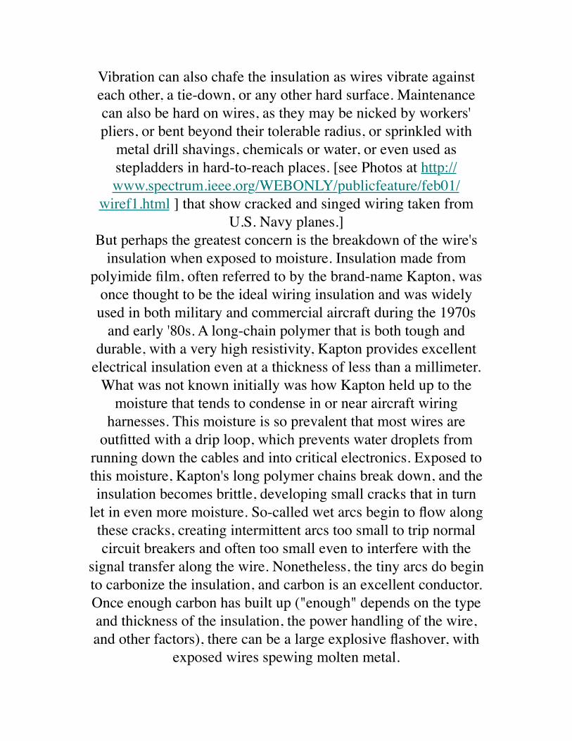
Vibration can also chafe the insulation as wires vibrate against each other, a tie-down, or any other hard surface. Maintenance can also be hard on wires, as they may be nicked by workers' pliers, or bent beyond their tolerable radius, or sprinkled with
metal drill shavings, chemicals or water, or even used as stepladders in hard-to-reach places. [see Photos at http://www.spectrum.ieee.org/WEBONLY/publicfeature/feb01/
wiref1.html ] that show cracked and singed wiring taken from U.S. Navy planes.]
But perhaps the greatest concern is the breakdown of the wire's insulation when exposed to moisture. Insulation made from
polyimide film, often referred to by the brand-name Kapton, was once thought to be the ideal wiring insulation and was widely used in both military and commercial aircraft during the 1970s
and early '80s. A long-chain polymer that is both tough and durable, with a very high resistivity, Kapton provides excellent
electrical insulation even at a thickness of less than a millimeter.What was not known initially was how Kapton held up to the
moisture that tends to condense in or near aircraft wiring harnesses. This moisture is so prevalent that most wires are
outfitted with a drip loop, which prevents water droplets from running down the cables and into critical electronics. Exposed to this moisture, Kapton's long polymer chains break down, and the insulation becomes brittle, developing small cracks that in turn
let in even more moisture. So-called wet arcs begin to flow along these cracks, creating intermittent arcs too small to trip normal circuit breakers and often too small even to interfere with the
signal transfer along the wire. Nonetheless, the tiny arcs do begin to carbonize the insulation, and carbon is an excellent conductor. Once enough carbon has built up ("enough" depends on the type and thickness of the insulation, the power handling of the wire, and other factors), there can be a large explosive flashover, with
exposed wires spewing molten metal.
One would hope that Kapton cracks are relatively rare. Not so, according to a recent report by Lectromechanical Design Co., an electrical research firm based in Sterling, Va. Using a proprietary tool called the DelTest, Letromec engineers tested the wiring in a
Boeing 747, an Airbus A300, a Lockheed L-1011, and two DC-9s that were each over 20 years old and had been retired by commercial airlines within the previous six months. The results:
13 cracks per 1000 meters of wire in the L-1011, down to 1.6 cracks per 1000 meters in one of the DC-9s. With approximately
240 km of wire in the L-1011, this amounted to over 3000 cracks, each a potential cause of catastrophic arcing.
Some time after Kapton's problems came to light, in the late '70s, its use was cut back, and aircraft manufacturers began replacing
it in some of the most critical wiring systems in planes in service. Alternatives to Kapton include polyvinylchloride, glass, nylon,
polyester, and teflon. But polyimide can still be found on thousands of aircraft in service, including the McDonnell
Douglas MD-11 and older Boeing 737s and 767s.How old is too old?
Updating rather than replacing old planes has become a standard way to save money. Some aircraft being designed today, such as the Joint Strike Fighter, may fly 100 years. Similarly, the B-52s
flown by the U.S. Air Force were built in 1961-62 and are expected to remain operational until 2045. Its designers would have never dreamed that this plane would fly for over 80 years. Indeed, not much thought was given to replacing or inspecting the wiring, because the planes were to have been retired long
before any problems developed.So when is it time to scrap an airplane because its wires are too old? The answer depends on a complex array of factors--among them calendar age, manufacturing variations, exposure to water, ultraviolet light, temperature, vibration and g-forces, and stress
during normal use and maintenance.Planes over 20 years old are virtually guaranteed to have wiring problems, many of which turn up during routine maintenance.
The average age of civilian aircraft in use today is 18 years, and the average age of military planes is 16 years. [See table at http://
www.spectrum.ieee.org/WEBONLY/publicfeature/feb01/wiret1.html ] Of course, most fleets are composed of a mix of
aircraft types and ages. Trying to relate this information to wiring failure probability rates, such as those in the table at http://www.spectrum.ieee.org/WEBONLY/publicfeature/feb01/
wiret2.html , gives some idea why wiring problems are endemic today.
Short of replacing an entire aircraft, how about replacing just the wiring system? That also turns out to be hugely expensive--
anywhere from US $1 million to $5 million for a typical aircraft. Determining what, when, or whether to replace then means
weighing cost against risk--a decision complicated by the fact that neither the cost nor the risk has yet been fully characterized.
What is more, military planes get exposed to more hostile environments than the average commercial plane, so
extrapolation to other types of planes is not necessarily accurate.The maintenance nightmare
Snaking through an aircraft are many kilometers of wire--some 17.5 km in a Navy F-18C/D fighter, 240 km in a typical wide-
body jet. The wire is literally built into the aircraft, running through fuel tanks, and twisted around hydraulic lines. Just
reaching the wiring harness often entails dismantling an aircraft's external structure. And merely touching a wire, let alone
disconnecting, handling, and reconnecting it, heightens the risk that the wire will be damaged.
But maintenance workers do not always show due respect. They have been known to stand on wires instead of step stools, to cut and splice them poorly to get them out of the way of difficult-to-
reach places, and to smack connectors with hammers to loosen them. Tiny razor-sharp metal shavings from maintenance or upgrades, coupled with ordinary aircraft vibration, create the
perfect conditions for insulation damage.
Other parts of the aircraft never get touched, but are no less problematic. The dust bunnies and chaff that collect in these out-of-sight areas are excellent tinder to turn sparks into smoke and
flames. Then there's the sticky "syrup" that collects in and around wire bundles. This well-aged potion of condensation, toilet and
galley leaks, dust, hydraulic fluid, and various unnamable ingredients is intensely caustic to most kinds of insulation. One of the Navy and FAA directives for making aging wiring safer
has been simply to improve cleanliness within aircraft!Compounding the maintenance nightmare is its high cost. By one estimate, the Navy spends 1.8 million person-hours each year to
troubleshoot and repair its aircraft wiring systems.Why state of the art isn't enough
Wire troubleshooting is still very much a hands-on art that has changed little over the last 40 years. Among the techniques in
current use are visual inspection, several versions of reflectometry, and impedance testing. Each technique has its
advantages and, more importantly, disadvantages.Visual inspection is still the most common way to check for
wiring failures. It entails accessing the cables and then carefully checking the insulation for holes and cracks, often no larger than the head of a pin. Whole sections of wiring never get inspected: chafed insulation can be hidden under clamps or around corners, or within multiwire bundles, each consisting of 75 or more wires.
And many wire bundles are built right into the walls of the aircraft.
Another approach involves measuring the cable's resistance from end to end. A low resistance means the cable is "good," and a
high resistance means that it is broken. When a very high voltage (500 V or more) is placed between adjacent, supposedly
unconnected wires, current leakage from one wire to another can indicate degraded insulation.
There is some concern, though, that high voltage may in itself damage the insulation. So nondestructive resistance tests, such as those developed by Eclypse International Corp., Corona, Calif., use voltages of 28 V or less. A floating comparator analyzes the
currents on the cable as the input current is stepped through several levels. In a healthy cable, Ohm's Law predicts that the
resistance will stay the same for all current levels. If it does not, then something is wrong with the cable. The method has been
used to locate cold solder joints, bad crimps, carbonization of the cable or connectors, and foreign matter on or near the cables. And unlike the high-voltage tests, it can be used on a fueled
airplane. It does, though, still require disconnecting and reconnecting the cables.
Several techniques now used or under development involve reflectometry. Common to all these methods is the sending of a
signal (a pulse, sine wave, or the like) down the wire and sensing the reflection that returns from the wire's end. They are most
useful for detecting so-called hard errors, such as short circuits, but have not proven useful for less obvious wire problems.
Time domain reflectometry (TDR) is customarily used when a wiring problem is already suspected. A short, typically rectangular pulse is sent down the cable, and the cable
impedance, termination, and length give a unique temporal signature to the reflected signal. A trained technician then
interprets the signature to determine the health of the cable. Such signal interpretation is particularly necessary for aircraft systems,
where wires branch into complicated network structures and connect to active avionics. The running joke about TDR is that it
requires a Ph.D. to use.
Standing-wave reflectometry (SWR) involves sending a sinusoidal waveform down the wire. A reflected sinusoid is returned from the wire's end, and the two signals add to a
standing wave on the line. The peaks and nulls of this standing wave give information on the length and terminating load of the cable; a healthy line's wave pattern will be distinct from that of a line with an open or short circuit. The edge this method has over
TDR is that the electronics are simpler and therefore less expensive.
Like SWR, frequency domain reflectometry (FDR) uses sine waves. FDR, though, directly measures the phase difference
between the incident and reflected waves; any faults in the line will generate resonances between the two signals. This method is
being developed for in situ wire testing by researchers at Utah State University with support from Management Sciences Inc., Albuquerque, N.M., and the Naval Air Systems Command. The
goal is to allow preflight testing of cables with the touch of a button, and without the risk of damaging the cables by
disconnecting them.On the horizon
Because of the shortcomings in the above techniques, researchers are now looking at several new technologies. These include
automated reflectometry testing; smart wire systems for real-time, on-the-spot testing; and, in the event of an in-flight failure, advanced fire suppression methods and arc-fault circuit breakers.Automating the reflectometry methods now in use may one day mean that maintenance workers will be able to gauge a cable's
health with minimal physical intervention. A hand-held unit would clamp around the wire, rather than directly connecting to
it. Recently, a fully automated TDR unit was developed by Phoenix Aviation and Technology. It provides a wider range of
fault diagnostics and prognostics, with precise location and
interpretation of the fault. The same software can be easily embedded into application-specific IC format or similar small
computing platforms, thus paving the way for real-time embedded conductor monitoring.
All the same, reflectometry is pushing the state of the art when it comes to finding small insulation cracks, detecting chafed
insulation before arcs occur, and locating an arc's source. Better detection of these tiny anomalies may be achievable by wetting the cable with water or saline solution, or filling the plane with
inert gas.Perhaps the maintenance worker's greatest nightmare is finding
faults that come and go. These so-called ticking faults arise from vibration, temperature change, moisture, g-forces,
electromagnetic interference, and so on. Diagnosing the problem requires systems that can function in flight, where ticking faults
usually occur.Smart wire systems are thus being designed for testing cables continuously, both before takeoff and during a flight. Systems
now under development include a frequency domain reflectometer, on-board processor, environmental sensors, and
wireless communication system integrated into a single miniaturized unit, hundreds of which can be embedded in the wiring system. They will monitor the health of the cable and
guide cable maintenance, and even detect any faults that occur and correct them in real time.
For the aircraft being designed today, a novel kind of wiring with a complete array of embedded sensors is being proposed. This is particularly critical for long-lived planes such as the Joint Strike
Fighter. Weight and space constraints are likely to drive this technology to nanoscale sensors, emerging material science technologies, and microelectromechanical system devices.
Of course, wire failures will still occur. New technologies that can help limit the damage in such an event include arc-fault
circuit breakers and fire suppression methods.------------------------------------------------------------------------------
--Smart wire systems will continuously monitor the cable's
health and correct faults as they occur------------------------------------------------------------------------------
--Ordinary circuit breakers are heat-sensitive bimetal elements that
trip only when a large current passes through the circuit long enough to heat the element. This power may be on the order of
1000 percent of the rated current for 0.35 to 0.8 seconds. By comparison, a single arc fault may last only 1.25 ms, and a series
of events may last 20-30 ms. Too fleeting to trip the circuit breaker, these arc faults can nonetheless cause catastrophic local damage to the wire. Fires have been known to break out with the
breaker still intact.Arc-fault circuit breakers contain sophisticated electronics to
sample the current on the wire at submillisecond intervals. Both time and frequency domain filtering are used to extract the arc-
fault signature from the current waveform. This signature may be integrated over time to discriminate, by means of pattern-
matching algorithms, between a normal current and a sputtering arc-fault current. And so ordinary transients, due to, say, a motor being turned on and off, can be distinguished from the random
current surges that occur with arcing.
Arc-fault breakers are already required in new home wiring in the United States and are now being miniaturized for use on
aircraft. Normally these breakers either are used in tandem with a traditional heat-sensitive breaker or else include a heat-sensitive element in addition to the pattern-matching electronics. Ideally, circuitry will also be added to locate the fault after the breaker
has tripped.
Once a fire starts on an aircraft, it spreads rapidly, aided by Mylar-backed insulation in the cabin walls, limited access to fire extinguishers, and so on. New extinguisher designs that rely on super-fine, high-pressure mists of water, inert gases, and other
techniques are now being developed to put out all types of aircraft fires, including those due to faulty wiring.
Amazingly little is known about how and why wires age, but polymer scientists are making up for lost time. Among other
things, they are studying the chemical and physical changes and resultant effects on electrical insulation properties that occur as wires age. One goal is to find new materials to replace copper
wiring in signal-transfer and electromagnetic interference shielding on aircraft, as well as new types of wire insulation that
resist chafing and have extended life and built-in diagnostics.Not to panic
If you happen to read this article while flying, do not panic. Few wiring problems end in disaster. There is cause for concern,
though, as the air fleet continues to age, and our reliance on air transport grows. While an aircraft's other major systems undergo
preflight testing and regular inspection and maintenance, its central nervous system--wiring--has been long neglected. Sorely needed are new maintenance methods that account for the aging of wires, as is done for aging structural and computer systems.Diagnosis is good. Prognosis is better. And prevention is better still. This last may require a new way of thinking for electrical
engineers, who tend to be more at home with obsolescence than geriatrics. For aging aircraft wiring, diagnostics and prevention
are improving, and prognostics are on the horizon. What remains to be seen is how all of these methods will be implemented in practical systems, so that disasters like TWA 800 and Swissair
111 can be prevented.Read the Full article (with links and images) here:
http://www.spectrum.ieee.org/WEBONLY/publicfeature/feb01/
wire.htmlhttp://www.iasa.com.au/professor_cynthia_furse.html
From: Mail Delivery Subsystem <[email protected]>Date: February 12, 2001 10:17:29 AM PSTTo: <[email protected]>Subject: Returned mail: see transcript for details
James F. (Jim) Wildey IISenior MetallurgistSequence Group Chairman, TWA flight 800 investigation.National Resource Specialist - Metallurgy
Experience:Employed at the Safety Board in the Materials Laboratory for nearly 25 years, since September, 1975. Chief of the laboratory for 2+ years. Participated in many of the major accidents involving component or structural failures investigated by the Board and foreign countries including 1985 Indian Airlines Boeing 747 bombing, Atlantic Ocean 1988 Aloha Airlines 737 structural failure, Hawaii 1988 Pan Am 103 bombing, Lockerbie, Scotland 1989 United Airlines 747 cargo door failure, Honolulu, Hawaii 1989 United Airlines DC-10 fan disk failure, Sioux City, Iowa 199? DC-10 bombing, Chad, Africa 1996 TWA 800 NTSB Chairman's award, (1989), Recipient of Aviation Week and Space Technology Laurel Award, February 1998, in recognition of the analysis of the breakup of the TWA 800 airplane. Presents a course entitled Fracture Recognition, to students at the NTSB Aircraft Accident Investigation School.
Dear Aviation Public Safety Officials, the one person who has a vested interest in TWA 800 not being a wiring/cargo door event
is Mr. Wildey. He is officially connected with AI 182 and PA 103, two events which are officially not wiring/cargo door events but would be if TWA 800 were to become a wiring/cargo door event. This would explain why he is so adamant that TWA 800 was not a cargo door rupture in flight, contrary to photographic and CVR evidence, but a spontaneous center tank explosion which lacks the crucial factor of an identified ignition source: He is protecting his opinions of years past, opinions in hindsight which are now suspect, based on matching evidence in the electrical/cargo door UAL 811 accident.
Mr. Wildey's opinions about the destruction sequence and whether the cargo door ruptured in flight are invalid as they are given by an official with a conflict of interest as well as the fact he is not an aircraft accident investigator.
Therefore the entire question of the initial event of TWA 800 and whether the cargo door opened in flight should be renewed by a NTSB aircraft accident investigator who is not connected to AI 182 or PA 103.
Below is a photograph of UAL 811 giving as evidence a similar shape of destruction on the starboard side of TWA 800. The port side of TWA 800 is as smooth as the port side of UAL 811. Both doors had ruptures at the midspan latches. They match in destruction evidence and probable cause, electrical/wiring/cargo door event.
Sincerely,
John Barry Smith
(831) 659-3552 phone551 Country Club Drive,Carmel Valley, CA [email protected] pilot, instrument rated, former FAA Part 135 certificate holder.US Navy reconnaissance navigator, RA-5C 650 hours.US Navy patrol crewman, P2V-5FS 2000 hours.Air Intelligence Officer, US NavyRetired US Army Major MSCOwner Mooney M-20C, 1000 hours.Survivor of sudden night fiery fatal jet plane crash in RA-5C
Aging, brittle wiring within aircraft poses a hidden hazard that emerging technologies aim to address
Down to the WireBy Cynthia Furse & Randy Haupt, Utah State University
As today's military and commercial aircraft age past their teen years, the many kilometers of wiring buried deep within their structures begin to crack and fray. Once thought to be rare and
benign, such faults are found by the hundreds in a typical aircraft. Unlike obvious cracks in a wing or an engine, though, damaged wire is extremely difficult to detect. But the resulting
arcing and electromagnetic emissions can be just as deadly: faulty wiring has been blamed for the downing of Swissair 111
near Nova Scotia in 1998 and of TWA 800 off New York's Long Island in 1996 [see http://www.spectrum.ieee.org/WEBONLY/publicfeature/feb01/wiref1.html ]. Indeed, any densely wired system is vulnerable--the space shuttle, nuclear power plants,
subways and railroads, even the family car.
Public scrutiny has prompted strongly worded recommendations from the likes of NASA, the U.S. Federal Aviation
Administration, and the National Transportation Safety Board (NTSB) [see "Government and Industry Take Action" at http://
www.spectrum.ieee.org/WEBONLY/publicfeature/feb01/wiresb1.html ]. "The safety of the nation's wire systems is an
issue of major importance to us all," noted a White House report issued last fall. Several months earlier, the NTSB concluded its lengthy investigation of TWA 800 with the verdict that a short circuit sparked an explosion in the center wing fuel tank. The
condition of the wiring, it noted, was "not atypical for an airplane of its age." Among the NTSB's recommendations was to
incorporate into aircraft "new technology, such as arc-fault circuit breakers and automated wire test equipment."
Solutions are not straightforward. Among the most promising technologies are advanced reflectometry methods, for routine
maintenance; so-called smart wire systems, for continual, on-the-spot wire testing; and arc-fault circuit breakers and advanced fire
suppression techniques, for minimizing damage and injury should a fault occur. Remaining challenges include detecting the minuscule insulation breaks that encourage arcing; optimizing the benefits and mitigating the risks of the various wire testing
techniques; and getting a better handle on the labyrinthine complexity of aircraft wiring systems.
Failing the test of timeA healthy wire is perhaps the simplest, yet most important,
element in an electrical system. Typically, a copper conductor (from 1 to 10 mm in diameter) is covered by a thin outer
insulation (from 0.5 to 2 mm thick). Damaged insulation can expose the copper, giving rise to arcs, shorts, and
electromagnetic emission and interference. Arcing occurs when current flows from the wire through ionized air to another
conducting object, such as a second wire or the aircraft structure. A short circuit channels the current to an undesired conductor. If
an external shield or braid protecting a wire is broken, the
resulting antenna radiates the signal on the wire.As the wire ages, the insulation may become brittle and crack. Vibration can also chafe the insulation as wires vibrate against each other, a tie-down, or any other hard surface. Maintenance can also be hard on wires, as they may be nicked by workers' pliers, or bent beyond their tolerable radius, or sprinkled with
metal drill shavings, chemicals or water, or even used as stepladders in hard-to-reach places. [see Photos at http://www.spectrum.ieee.org/WEBONLY/publicfeature/feb01/
wiref1.html ] that show cracked and singed wiring taken from U.S. Navy planes.]
But perhaps the greatest concern is the breakdown of the wire's insulation when exposed to moisture. Insulation made from
polyimide film, often referred to by the brand-name Kapton, was once thought to be the ideal wiring insulation and was widely used in both military and commercial aircraft during the 1970s
and early '80s. A long-chain polymer that is both tough and durable, with a very high resistivity, Kapton provides excellent
electrical insulation even at a thickness of less than a millimeter.What was not known initially was how Kapton held up to the
moisture that tends to condense in or near aircraft wiring harnesses. This moisture is so prevalent that most wires are
outfitted with a drip loop, which prevents water droplets from running down the cables and into critical electronics. Exposed to this moisture, Kapton's long polymer chains break down, and the insulation becomes brittle, developing small cracks that in turn
let in even more moisture. So-called wet arcs begin to flow along these cracks, creating intermittent arcs too small to trip normal circuit breakers and often too small even to interfere with the
signal transfer along the wire. Nonetheless, the tiny arcs do begin to carbonize the insulation, and carbon is an excellent conductor. Once enough carbon has built up ("enough" depends on the type and thickness of the insulation, the power handling of the wire,
and other factors), there can be a large explosive flashover, with exposed wires spewing molten metal.
One would hope that Kapton cracks are relatively rare. Not so, according to a recent report by Lectromechanical Design Co., an electrical research firm based in Sterling, Va. Using a proprietary tool called the DelTest, Letromec engineers tested the wiring in a
Boeing 747, an Airbus A300, a Lockheed L-1011, and two DC-9s that were each over 20 years old and had been retired by commercial airlines within the previous six months. The results:
13 cracks per 1000 meters of wire in the L-1011, down to 1.6 cracks per 1000 meters in one of the DC-9s. With approximately
240 km of wire in the L-1011, this amounted to over 3000 cracks, each a potential cause of catastrophic arcing.
Some time after Kapton's problems came to light, in the late '70s, its use was cut back, and aircraft manufacturers began replacing
it in some of the most critical wiring systems in planes in service. Alternatives to Kapton include polyvinylchloride, glass, nylon,
polyester, and teflon. But polyimide can still be found on thousands of aircraft in service, including the McDonnell
Douglas MD-11 and older Boeing 737s and 767s.How old is too old?
Updating rather than replacing old planes has become a standard way to save money. Some aircraft being designed today, such as the Joint Strike Fighter, may fly 100 years. Similarly, the B-52s
flown by the U.S. Air Force were built in 1961-62 and are expected to remain operational until 2045. Its designers would have never dreamed that this plane would fly for over 80 years. Indeed, not much thought was given to replacing or inspecting the wiring, because the planes were to have been retired long
before any problems developed.So when is it time to scrap an airplane because its wires are too old? The answer depends on a complex array of factors--among
them calendar age, manufacturing variations, exposure to water, ultraviolet light, temperature, vibration and g-forces, and stress
during normal use and maintenance.Planes over 20 years old are virtually guaranteed to have wiring problems, many of which turn up during routine maintenance.
The average age of civilian aircraft in use today is 18 years, and the average age of military planes is 16 years. [See table at http://
www.spectrum.ieee.org/WEBONLY/publicfeature/feb01/wiret1.html ] Of course, most fleets are composed of a mix of
aircraft types and ages. Trying to relate this information to wiring failure probability rates, such as those in the table at http://www.spectrum.ieee.org/WEBONLY/publicfeature/feb01/
wiret2.html , gives some idea why wiring problems are endemic today.
Short of replacing an entire aircraft, how about replacing just the wiring system? That also turns out to be hugely expensive--
anywhere from US $1 million to $5 million for a typical aircraft. Determining what, when, or whether to replace then means
weighing cost against risk--a decision complicated by the fact that neither the cost nor the risk has yet been fully characterized.
What is more, military planes get exposed to more hostile environments than the average commercial plane, so
extrapolation to other types of planes is not necessarily accurate.The maintenance nightmare
Snaking through an aircraft are many kilometers of wire--some 17.5 km in a Navy F-18C/D fighter, 240 km in a typical wide-
body jet. The wire is literally built into the aircraft, running through fuel tanks, and twisted around hydraulic lines. Just
reaching the wiring harness often entails dismantling an aircraft's external structure. And merely touching a wire, let alone
disconnecting, handling, and reconnecting it, heightens the risk that the wire will be damaged.
But maintenance workers do not always show due respect. They
have been known to stand on wires instead of step stools, to cut and splice them poorly to get them out of the way of difficult-to-reach places, and to smack connectors with hammers to loosen
them. Tiny razor-sharp metal shavings from maintenance or upgrades, coupled with ordinary aircraft vibration, create the
perfect conditions for insulation damage.
Other parts of the aircraft never get touched, but are no less problematic. The dust bunnies and chaff that collect in these out-of-sight areas are excellent tinder to turn sparks into smoke and
flames. Then there's the sticky "syrup" that collects in and around wire bundles. This well-aged potion of condensation, toilet and
galley leaks, dust, hydraulic fluid, and various unnamable ingredients is intensely caustic to most kinds of insulation. One of the Navy and FAA directives for making aging wiring safer
has been simply to improve cleanliness within aircraft!Compounding the maintenance nightmare is its high cost. By one estimate, the Navy spends 1.8 million person-hours each year to
troubleshoot and repair its aircraft wiring systems.Why state of the art isn't enough
Wire troubleshooting is still very much a hands-on art that has changed little over the last 40 years. Among the techniques in
current use are visual inspection, several versions of reflectometry, and impedance testing. Each technique has its
advantages and, more importantly, disadvantages.Visual inspection is still the most common way to check for
wiring failures. It entails accessing the cables and then carefully checking the insulation for holes and cracks, often no larger than the head of a pin. Whole sections of wiring never get inspected: chafed insulation can be hidden under clamps or around corners, or within multiwire bundles, each consisting of 75 or more wires.
And many wire bundles are built right into the walls of the aircraft.
Another approach involves measuring the cable's resistance from end to end. A low resistance means the cable is "good," and a
high resistance means that it is broken. When a very high voltage (500 V or more) is placed between adjacent, supposedly
unconnected wires, current leakage from one wire to another can indicate degraded insulation.
There is some concern, though, that high voltage may in itself damage the insulation. So nondestructive resistance tests, such as those developed by Eclypse International Corp., Corona, Calif., use voltages of 28 V or less. A floating comparator analyzes the
currents on the cable as the input current is stepped through several levels. In a healthy cable, Ohm's Law predicts that the
resistance will stay the same for all current levels. If it does not, then something is wrong with the cable. The method has been
used to locate cold solder joints, bad crimps, carbonization of the cable or connectors, and foreign matter on or near the cables. And unlike the high-voltage tests, it can be used on a fueled
airplane. It does, though, still require disconnecting and reconnecting the cables.
Several techniques now used or under development involve reflectometry. Common to all these methods is the sending of a
signal (a pulse, sine wave, or the like) down the wire and sensing the reflection that returns from the wire's end. They are most
useful for detecting so-called hard errors, such as short circuits, but have not proven useful for less obvious wire problems.
Time domain reflectometry (TDR) is customarily used when a wiring problem is already suspected. A short, typically rectangular pulse is sent down the cable, and the cable
impedance, termination, and length give a unique temporal signature to the reflected signal. A trained technician then
interprets the signature to determine the health of the cable. Such signal interpretation is particularly necessary for aircraft systems,
where wires branch into complicated network structures and
connect to active avionics. The running joke about TDR is that it requires a Ph.D. to use.
Standing-wave reflectometry (SWR) involves sending a sinusoidal waveform down the wire. A reflected sinusoid is returned from the wire's end, and the two signals add to a
standing wave on the line. The peaks and nulls of this standing wave give information on the length and terminating load of the cable; a healthy line's wave pattern will be distinct from that of a line with an open or short circuit. The edge this method has over
TDR is that the electronics are simpler and therefore less expensive.
Like SWR, frequency domain reflectometry (FDR) uses sine waves. FDR, though, directly measures the phase difference
between the incident and reflected waves; any faults in the line will generate resonances between the two signals. This method is
being developed for in situ wire testing by researchers at Utah State University with support from Management Sciences Inc., Albuquerque, N.M., and the Naval Air Systems Command. The
goal is to allow preflight testing of cables with the touch of a button, and without the risk of damaging the cables by
disconnecting them.On the horizon
Because of the shortcomings in the above techniques, researchers are now looking at several new technologies. These include
automated reflectometry testing; smart wire systems for real-time, on-the-spot testing; and, in the event of an in-flight failure, advanced fire suppression methods and arc-fault circuit breakers.Automating the reflectometry methods now in use may one day mean that maintenance workers will be able to gauge a cable's
health with minimal physical intervention. A hand-held unit would clamp around the wire, rather than directly connecting to
it. Recently, a fully automated TDR unit was developed by
Phoenix Aviation and Technology. It provides a wider range of fault diagnostics and prognostics, with precise location and interpretation of the fault. The same software can be easily
embedded into application-specific IC format or similar small computing platforms, thus paving the way for real-time
embedded conductor monitoring.All the same, reflectometry is pushing the state of the art when it
comes to finding small insulation cracks, detecting chafed insulation before arcs occur, and locating an arc's source. Better detection of these tiny anomalies may be achievable by wetting the cable with water or saline solution, or filling the plane with
inert gas.Perhaps the maintenance worker's greatest nightmare is finding
faults that come and go. These so-called ticking faults arise from vibration, temperature change, moisture, g-forces,
electromagnetic interference, and so on. Diagnosing the problem requires systems that can function in flight, where ticking faults
usually occur.Smart wire systems are thus being designed for testing cables continuously, both before takeoff and during a flight. Systems
now under development include a frequency domain reflectometer, on-board processor, environmental sensors, and
wireless communication system integrated into a single miniaturized unit, hundreds of which can be embedded in the wiring system. They will monitor the health of the cable and
guide cable maintenance, and even detect any faults that occur and correct them in real time.
For the aircraft being designed today, a novel kind of wiring with a complete array of embedded sensors is being proposed. This is particularly critical for long-lived planes such as the Joint Strike
Fighter. Weight and space constraints are likely to drive this technology to nanoscale sensors, emerging material science technologies, and microelectromechanical system devices.
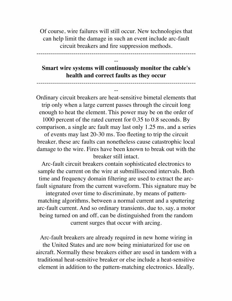
Of course, wire failures will still occur. New technologies that can help limit the damage in such an event include arc-fault
circuit breakers and fire suppression methods.------------------------------------------------------------------------------
--Smart wire systems will continuously monitor the cable's
health and correct faults as they occur------------------------------------------------------------------------------
--Ordinary circuit breakers are heat-sensitive bimetal elements that
trip only when a large current passes through the circuit long enough to heat the element. This power may be on the order of
1000 percent of the rated current for 0.35 to 0.8 seconds. By comparison, a single arc fault may last only 1.25 ms, and a series
of events may last 20-30 ms. Too fleeting to trip the circuit breaker, these arc faults can nonetheless cause catastrophic local damage to the wire. Fires have been known to break out with the
breaker still intact.Arc-fault circuit breakers contain sophisticated electronics to
sample the current on the wire at submillisecond intervals. Both time and frequency domain filtering are used to extract the arc-
fault signature from the current waveform. This signature may be integrated over time to discriminate, by means of pattern-
matching algorithms, between a normal current and a sputtering arc-fault current. And so ordinary transients, due to, say, a motor being turned on and off, can be distinguished from the random
current surges that occur with arcing.
Arc-fault breakers are already required in new home wiring in the United States and are now being miniaturized for use on
aircraft. Normally these breakers either are used in tandem with a traditional heat-sensitive breaker or else include a heat-sensitive element in addition to the pattern-matching electronics. Ideally,
circuitry will also be added to locate the fault after the breaker has tripped.
Once a fire starts on an aircraft, it spreads rapidly, aided by Mylar-backed insulation in the cabin walls, limited access to fire extinguishers, and so on. New extinguisher designs that rely on super-fine, high-pressure mists of water, inert gases, and other
techniques are now being developed to put out all types of aircraft fires, including those due to faulty wiring.
Amazingly little is known about how and why wires age, but polymer scientists are making up for lost time. Among other
things, they are studying the chemical and physical changes and resultant effects on electrical insulation properties that occur as wires age. One goal is to find new materials to replace copper
wiring in signal-transfer and electromagnetic interference shielding on aircraft, as well as new types of wire insulation that
resist chafing and have extended life and built-in diagnostics.Not to panic
If you happen to read this article while flying, do not panic. Few wiring problems end in disaster. There is cause for concern,
though, as the air fleet continues to age, and our reliance on air transport grows. While an aircraft's other major systems undergo
preflight testing and regular inspection and maintenance, its central nervous system--wiring--has been long neglected. Sorely needed are new maintenance methods that account for the aging of wires, as is done for aging structural and computer systems.Diagnosis is good. Prognosis is better. And prevention is better still. This last may require a new way of thinking for electrical
engineers, who tend to be more at home with obsolescence than geriatrics. For aging aircraft wiring, diagnostics and prevention
are improving, and prognostics are on the horizon. What remains to be seen is how all of these methods will be implemented in practical systems, so that disasters like TWA 800 and Swissair
111 can be prevented.
Read the Full article (with links and images) here:http://www.spectrum.ieee.org/WEBONLY/publicfeature/feb01/
wire.htmlhttp://www.iasa.com.au/professor_cynthia_furse.html
From: Mail Delivery Subsystem <[email protected]>Date: February 12, 2001 10:17:59 AM PSTTo: <[email protected]>Subject: Returned mail: see transcript for details
James F. (Jim) Wildey IISenior MetallurgistSequence Group Chairman, TWA flight 800 investigation.National Resource Specialist - Metallurgy
Experience:Employed at the Safety Board in the Materials Laboratory for nearly 25 years, since September, 1975. Chief of the laboratory for 2+ years. Participated in many of the major accidents involving component or structural failures investigated by the Board and foreign countries including 1985 Indian Airlines Boeing 747 bombing, Atlantic Ocean 1988 Aloha Airlines 737 structural failure, Hawaii 1988 Pan Am 103 bombing, Lockerbie, Scotland 1989 United Airlines 747 cargo door failure, Honolulu, Hawaii 1989 United Airlines DC-10 fan disk failure, Sioux City, Iowa 199? DC-10 bombing, Chad, Africa 1996 TWA 800 NTSB Chairman's award, (1989), Recipient of Aviation Week and Space Technology Laurel Award, February 1998, in recognition of the analysis of the breakup of the TWA 800 airplane. Presents a course entitled Fracture Recognition, to students at the NTSB Aircraft Accident Investigation School.
Dear Aviation Public Safety Officials, the one person who has a vested interest in TWA 800 not being a wiring/cargo door event is Mr. Wildey. He is officially connected with AI 182 and PA 103, two events which are officially not wiring/cargo door events but would be if TWA 800 were to become a wiring/cargo door event. This would explain why he is so adamant that TWA 800 was not a cargo door rupture in flight, contrary to photographic and CVR evidence, but a spontaneous center tank explosion which lacks the crucial factor of an identified ignition source: He is protecting his opinions of years past, opinions in hindsight which are now suspect, based on matching evidence in the electrical/cargo door UAL 811 accident.
Mr. Wildey's opinions about the destruction sequence and whether the cargo door ruptured in flight are invalid as they are given by an official with a conflict of interest as well as the fact he is not an aircraft accident investigator.
Therefore the entire question of the initial event of TWA 800 and whether the cargo door opened in flight should be renewed by a NTSB aircraft accident investigator who is not connected to AI 182 or PA 103.
Below is a photograph of UAL 811 giving as evidence a similar shape of destruction on the starboard side of TWA 800. The port side of TWA 800 is as smooth as the port side of UAL 811. Both doors had ruptures at the midspan latches. They match in destruction evidence and probable cause, electrical/wiring/cargo door event.
Sincerely,
John Barry Smith(831) 659-3552 phone551 Country Club Drive,Carmel Valley, CA [email protected] pilot, instrument rated, former FAA Part 135 certificate holder.US Navy reconnaissance navigator, RA-5C 650 hours.US Navy patrol crewman, P2V-5FS 2000 hours.Air Intelligence Officer, US NavyRetired US Army Major MSCOwner Mooney M-20C, 1000 hours.Survivor of sudden night fiery fatal jet plane crash in RA-5C
Aging, brittle wiring within aircraft poses a hidden hazard that emerging technologies aim to address
Down to the WireBy Cynthia Furse & Randy Haupt, Utah State University
As today's military and commercial aircraft age past their teen years, the many kilometers of wiring buried deep within their structures begin to crack and fray. Once thought to be rare and
benign, such faults are found by the hundreds in a typical aircraft. Unlike obvious cracks in a wing or an engine, though, damaged wire is extremely difficult to detect. But the resulting
arcing and electromagnetic emissions can be just as deadly: faulty wiring has been blamed for the downing of Swissair 111
near Nova Scotia in 1998 and of TWA 800 off New York's Long Island in 1996 [see http://www.spectrum.ieee.org/WEBONLY/publicfeature/feb01/wiref1.html ]. Indeed, any densely wired system is vulnerable--the space shuttle, nuclear power plants,
subways and railroads, even the family car.
Public scrutiny has prompted strongly worded recommendations from the likes of NASA, the U.S. Federal Aviation
Administration, and the National Transportation Safety Board (NTSB) [see "Government and Industry Take Action" at http://
www.spectrum.ieee.org/WEBONLY/publicfeature/feb01/wiresb1.html ]. "The safety of the nation's wire systems is an
issue of major importance to us all," noted a White House report issued last fall. Several months earlier, the NTSB concluded its lengthy investigation of TWA 800 with the verdict that a short circuit sparked an explosion in the center wing fuel tank. The
condition of the wiring, it noted, was "not atypical for an airplane of its age." Among the NTSB's recommendations was to
incorporate into aircraft "new technology, such as arc-fault circuit breakers and automated wire test equipment."
Solutions are not straightforward. Among the most promising technologies are advanced reflectometry methods, for routine
maintenance; so-called smart wire systems, for continual, on-the-spot wire testing; and arc-fault circuit breakers and advanced fire
suppression techniques, for minimizing damage and injury should a fault occur. Remaining challenges include detecting the minuscule insulation breaks that encourage arcing; optimizing the benefits and mitigating the risks of the various wire testing
techniques; and getting a better handle on the labyrinthine complexity of aircraft wiring systems.
Failing the test of timeA healthy wire is perhaps the simplest, yet most important,
element in an electrical system. Typically, a copper conductor (from 1 to 10 mm in diameter) is covered by a thin outer
insulation (from 0.5 to 2 mm thick). Damaged insulation can expose the copper, giving rise to arcs, shorts, and
electromagnetic emission and interference. Arcing occurs when current flows from the wire through ionized air to another
conducting object, such as a second wire or the aircraft structure.
A short circuit channels the current to an undesired conductor. If an external shield or braid protecting a wire is broken, the
resulting antenna radiates the signal on the wire.As the wire ages, the insulation may become brittle and crack. Vibration can also chafe the insulation as wires vibrate against each other, a tie-down, or any other hard surface. Maintenance can also be hard on wires, as they may be nicked by workers' pliers, or bent beyond their tolerable radius, or sprinkled with
metal drill shavings, chemicals or water, or even used as stepladders in hard-to-reach places. [see Photos at http://www.spectrum.ieee.org/WEBONLY/publicfeature/feb01/
wiref1.html ] that show cracked and singed wiring taken from U.S. Navy planes.]
But perhaps the greatest concern is the breakdown of the wire's insulation when exposed to moisture. Insulation made from
polyimide film, often referred to by the brand-name Kapton, was once thought to be the ideal wiring insulation and was widely used in both military and commercial aircraft during the 1970s
and early '80s. A long-chain polymer that is both tough and durable, with a very high resistivity, Kapton provides excellent
electrical insulation even at a thickness of less than a millimeter.What was not known initially was how Kapton held up to the
moisture that tends to condense in or near aircraft wiring harnesses. This moisture is so prevalent that most wires are
outfitted with a drip loop, which prevents water droplets from running down the cables and into critical electronics. Exposed to this moisture, Kapton's long polymer chains break down, and the insulation becomes brittle, developing small cracks that in turn
let in even more moisture. So-called wet arcs begin to flow along these cracks, creating intermittent arcs too small to trip normal circuit breakers and often too small even to interfere with the
signal transfer along the wire. Nonetheless, the tiny arcs do begin to carbonize the insulation, and carbon is an excellent conductor.
Once enough carbon has built up ("enough" depends on the type and thickness of the insulation, the power handling of the wire, and other factors), there can be a large explosive flashover, with
exposed wires spewing molten metal.
One would hope that Kapton cracks are relatively rare. Not so, according to a recent report by Lectromechanical Design Co., an electrical research firm based in Sterling, Va. Using a proprietary tool called the DelTest, Letromec engineers tested the wiring in a
Boeing 747, an Airbus A300, a Lockheed L-1011, and two DC-9s that were each over 20 years old and had been retired by commercial airlines within the previous six months. The results:
13 cracks per 1000 meters of wire in the L-1011, down to 1.6 cracks per 1000 meters in one of the DC-9s. With approximately
240 km of wire in the L-1011, this amounted to over 3000 cracks, each a potential cause of catastrophic arcing.
Some time after Kapton's problems came to light, in the late '70s, its use was cut back, and aircraft manufacturers began replacing
it in some of the most critical wiring systems in planes in service. Alternatives to Kapton include polyvinylchloride, glass, nylon,
polyester, and teflon. But polyimide can still be found on thousands of aircraft in service, including the McDonnell
Douglas MD-11 and older Boeing 737s and 767s.How old is too old?
Updating rather than replacing old planes has become a standard way to save money. Some aircraft being designed today, such as the Joint Strike Fighter, may fly 100 years. Similarly, the B-52s
flown by the U.S. Air Force were built in 1961-62 and are expected to remain operational until 2045. Its designers would have never dreamed that this plane would fly for over 80 years. Indeed, not much thought was given to replacing or inspecting the wiring, because the planes were to have been retired long
before any problems developed.
So when is it time to scrap an airplane because its wires are too old? The answer depends on a complex array of factors--among them calendar age, manufacturing variations, exposure to water, ultraviolet light, temperature, vibration and g-forces, and stress
during normal use and maintenance.Planes over 20 years old are virtually guaranteed to have wiring problems, many of which turn up during routine maintenance.
The average age of civilian aircraft in use today is 18 years, and the average age of military planes is 16 years. [See table at http://
www.spectrum.ieee.org/WEBONLY/publicfeature/feb01/wiret1.html ] Of course, most fleets are composed of a mix of
aircraft types and ages. Trying to relate this information to wiring failure probability rates, such as those in the table at http://www.spectrum.ieee.org/WEBONLY/publicfeature/feb01/
wiret2.html , gives some idea why wiring problems are endemic today.
Short of replacing an entire aircraft, how about replacing just the wiring system? That also turns out to be hugely expensive--
anywhere from US $1 million to $5 million for a typical aircraft. Determining what, when, or whether to replace then means
weighing cost against risk--a decision complicated by the fact that neither the cost nor the risk has yet been fully characterized.
What is more, military planes get exposed to more hostile environments than the average commercial plane, so
extrapolation to other types of planes is not necessarily accurate.The maintenance nightmare
Snaking through an aircraft are many kilometers of wire--some 17.5 km in a Navy F-18C/D fighter, 240 km in a typical wide-
body jet. The wire is literally built into the aircraft, running through fuel tanks, and twisted around hydraulic lines. Just
reaching the wiring harness often entails dismantling an aircraft's external structure. And merely touching a wire, let alone
disconnecting, handling, and reconnecting it, heightens the risk
that the wire will be damaged.But maintenance workers do not always show due respect. They have been known to stand on wires instead of step stools, to cut and splice them poorly to get them out of the way of difficult-to-reach places, and to smack connectors with hammers to loosen
them. Tiny razor-sharp metal shavings from maintenance or upgrades, coupled with ordinary aircraft vibration, create the
perfect conditions for insulation damage.
Other parts of the aircraft never get touched, but are no less problematic. The dust bunnies and chaff that collect in these out-of-sight areas are excellent tinder to turn sparks into smoke and
flames. Then there's the sticky "syrup" that collects in and around wire bundles. This well-aged potion of condensation, toilet and
galley leaks, dust, hydraulic fluid, and various unnamable ingredients is intensely caustic to most kinds of insulation. One of the Navy and FAA directives for making aging wiring safer
has been simply to improve cleanliness within aircraft!Compounding the maintenance nightmare is its high cost. By one estimate, the Navy spends 1.8 million person-hours each year to
troubleshoot and repair its aircraft wiring systems.Why state of the art isn't enough
Wire troubleshooting is still very much a hands-on art that has changed little over the last 40 years. Among the techniques in
current use are visual inspection, several versions of reflectometry, and impedance testing. Each technique has its
advantages and, more importantly, disadvantages.Visual inspection is still the most common way to check for
wiring failures. It entails accessing the cables and then carefully checking the insulation for holes and cracks, often no larger than the head of a pin. Whole sections of wiring never get inspected: chafed insulation can be hidden under clamps or around corners, or within multiwire bundles, each consisting of 75 or more wires.
And many wire bundles are built right into the walls of the aircraft.
Another approach involves measuring the cable's resistance from end to end. A low resistance means the cable is "good," and a
high resistance means that it is broken. When a very high voltage (500 V or more) is placed between adjacent, supposedly
unconnected wires, current leakage from one wire to another can indicate degraded insulation.
There is some concern, though, that high voltage may in itself damage the insulation. So nondestructive resistance tests, such as those developed by Eclypse International Corp., Corona, Calif., use voltages of 28 V or less. A floating comparator analyzes the
currents on the cable as the input current is stepped through several levels. In a healthy cable, Ohm's Law predicts that the
resistance will stay the same for all current levels. If it does not, then something is wrong with the cable. The method has been
used to locate cold solder joints, bad crimps, carbonization of the cable or connectors, and foreign matter on or near the cables. And unlike the high-voltage tests, it can be used on a fueled
airplane. It does, though, still require disconnecting and reconnecting the cables.
Several techniques now used or under development involve reflectometry. Common to all these methods is the sending of a
signal (a pulse, sine wave, or the like) down the wire and sensing the reflection that returns from the wire's end. They are most
useful for detecting so-called hard errors, such as short circuits, but have not proven useful for less obvious wire problems.
Time domain reflectometry (TDR) is customarily used when a wiring problem is already suspected. A short, typically rectangular pulse is sent down the cable, and the cable
impedance, termination, and length give a unique temporal signature to the reflected signal. A trained technician then
interprets the signature to determine the health of the cable. Such
signal interpretation is particularly necessary for aircraft systems, where wires branch into complicated network structures and
connect to active avionics. The running joke about TDR is that it requires a Ph.D. to use.
Standing-wave reflectometry (SWR) involves sending a sinusoidal waveform down the wire. A reflected sinusoid is returned from the wire's end, and the two signals add to a
standing wave on the line. The peaks and nulls of this standing wave give information on the length and terminating load of the cable; a healthy line's wave pattern will be distinct from that of a line with an open or short circuit. The edge this method has over
TDR is that the electronics are simpler and therefore less expensive.
Like SWR, frequency domain reflectometry (FDR) uses sine waves. FDR, though, directly measures the phase difference
between the incident and reflected waves; any faults in the line will generate resonances between the two signals. This method is
being developed for in situ wire testing by researchers at Utah State University with support from Management Sciences Inc., Albuquerque, N.M., and the Naval Air Systems Command. The
goal is to allow preflight testing of cables with the touch of a button, and without the risk of damaging the cables by
disconnecting them.On the horizon
Because of the shortcomings in the above techniques, researchers are now looking at several new technologies. These include
automated reflectometry testing; smart wire systems for real-time, on-the-spot testing; and, in the event of an in-flight failure, advanced fire suppression methods and arc-fault circuit breakers.Automating the reflectometry methods now in use may one day mean that maintenance workers will be able to gauge a cable's
health with minimal physical intervention. A hand-held unit
would clamp around the wire, rather than directly connecting to it. Recently, a fully automated TDR unit was developed by
Phoenix Aviation and Technology. It provides a wider range of fault diagnostics and prognostics, with precise location and interpretation of the fault. The same software can be easily
embedded into application-specific IC format or similar small computing platforms, thus paving the way for real-time
embedded conductor monitoring.All the same, reflectometry is pushing the state of the art when it
comes to finding small insulation cracks, detecting chafed insulation before arcs occur, and locating an arc's source. Better detection of these tiny anomalies may be achievable by wetting the cable with water or saline solution, or filling the plane with
inert gas.Perhaps the maintenance worker's greatest nightmare is finding
faults that come and go. These so-called ticking faults arise from vibration, temperature change, moisture, g-forces,
electromagnetic interference, and so on. Diagnosing the problem requires systems that can function in flight, where ticking faults
usually occur.Smart wire systems are thus being designed for testing cables continuously, both before takeoff and during a flight. Systems
now under development include a frequency domain reflectometer, on-board processor, environmental sensors, and
wireless communication system integrated into a single miniaturized unit, hundreds of which can be embedded in the wiring system. They will monitor the health of the cable and
guide cable maintenance, and even detect any faults that occur and correct them in real time.
For the aircraft being designed today, a novel kind of wiring with a complete array of embedded sensors is being proposed. This is particularly critical for long-lived planes such as the Joint Strike
Fighter. Weight and space constraints are likely to drive this
technology to nanoscale sensors, emerging material science technologies, and microelectromechanical system devices.
Of course, wire failures will still occur. New technologies that can help limit the damage in such an event include arc-fault
circuit breakers and fire suppression methods.------------------------------------------------------------------------------
--Smart wire systems will continuously monitor the cable's
health and correct faults as they occur------------------------------------------------------------------------------
--Ordinary circuit breakers are heat-sensitive bimetal elements that
trip only when a large current passes through the circuit long enough to heat the element. This power may be on the order of
1000 percent of the rated current for 0.35 to 0.8 seconds. By comparison, a single arc fault may last only 1.25 ms, and a series
of events may last 20-30 ms. Too fleeting to trip the circuit breaker, these arc faults can nonetheless cause catastrophic local damage to the wire. Fires have been known to break out with the
breaker still intact.Arc-fault circuit breakers contain sophisticated electronics to
sample the current on the wire at submillisecond intervals. Both time and frequency domain filtering are used to extract the arc-
fault signature from the current waveform. This signature may be integrated over time to discriminate, by means of pattern-
matching algorithms, between a normal current and a sputtering arc-fault current. And so ordinary transients, due to, say, a motor being turned on and off, can be distinguished from the random
current surges that occur with arcing.
Arc-fault breakers are already required in new home wiring in the United States and are now being miniaturized for use on
aircraft. Normally these breakers either are used in tandem with a
traditional heat-sensitive breaker or else include a heat-sensitive element in addition to the pattern-matching electronics. Ideally, circuitry will also be added to locate the fault after the breaker
has tripped.Once a fire starts on an aircraft, it spreads rapidly, aided by
Mylar-backed insulation in the cabin walls, limited access to fire extinguishers, and so on. New extinguisher designs that rely on super-fine, high-pressure mists of water, inert gases, and other
techniques are now being developed to put out all types of aircraft fires, including those due to faulty wiring.
Amazingly little is known about how and why wires age, but polymer scientists are making up for lost time. Among other
things, they are studying the chemical and physical changes and resultant effects on electrical insulation properties that occur as wires age. One goal is to find new materials to replace copper
wiring in signal-transfer and electromagnetic interference shielding on aircraft, as well as new types of wire insulation that
resist chafing and have extended life and built-in diagnostics.Not to panic
If you happen to read this article while flying, do not panic. Few wiring problems end in disaster. There is cause for concern,
though, as the air fleet continues to age, and our reliance on air transport grows. While an aircraft's other major systems undergo
preflight testing and regular inspection and maintenance, its central nervous system--wiring--has been long neglected. Sorely needed are new maintenance methods that account for the aging of wires, as is done for aging structural and computer systems.Diagnosis is good. Prognosis is better. And prevention is better still. This last may require a new way of thinking for electrical
engineers, who tend to be more at home with obsolescence than geriatrics. For aging aircraft wiring, diagnostics and prevention
are improving, and prognostics are on the horizon. What remains to be seen is how all of these methods will be implemented in
practical systems, so that disasters like TWA 800 and Swissair 111 can be prevented.
Read the Full article (with links and images) here:http://www.spectrum.ieee.org/WEBONLY/publicfeature/feb01/
wire.htmlhttp://www.iasa.com.au/professor_cynthia_furse.html
From: Mail Delivery Subsystem <[email protected]>Date: February 12, 2001 10:18:30 AM PSTTo: <[email protected]>Subject: Returned mail: see transcript for details
James F. (Jim) Wildey IISenior MetallurgistSequence Group Chairman, TWA flight 800 investigation.National Resource Specialist - Metallurgy
Experience:Employed at the Safety Board in the Materials Laboratory for nearly 25 years, since September, 1975. Chief of the laboratory for 2+ years. Participated in many of the major accidents involving component or structural failures investigated by the Board and foreign countries including 1985 Indian Airlines Boeing 747 bombing, Atlantic Ocean 1988 Aloha Airlines 737 structural failure, Hawaii 1988 Pan Am 103 bombing, Lockerbie, Scotland 1989 United Airlines 747 cargo door failure, Honolulu, Hawaii 1989 United Airlines DC-10 fan disk failure, Sioux City, Iowa 199? DC-10 bombing, Chad, Africa 1996 TWA 800 NTSB Chairman's award, (1989), Recipient of Aviation Week and Space Technology Laurel Award, February 1998, in recognition of the analysis of the breakup of the TWA 800 airplane. Presents a course entitled Fracture Recognition, to students at the NTSB
Aircraft Accident Investigation School.
Dear Aviation Public Safety Officials, the one person who has a vested interest in TWA 800 not being a wiring/cargo door event is Mr. Wildey. He is officially connected with AI 182 and PA 103, two events which are officially not wiring/cargo door events but would be if TWA 800 were to become a wiring/cargo door event. This would explain why he is so adamant that TWA 800 was not a cargo door rupture in flight, contrary to photographic and CVR evidence, but a spontaneous center tank explosion which lacks the crucial factor of an identified ignition source: He is protecting his opinions of years past, opinions in hindsight which are now suspect, based on matching evidence in the electrical/cargo door UAL 811 accident.
Mr. Wildey's opinions about the destruction sequence and whether the cargo door ruptured in flight are invalid as they are given by an official with a conflict of interest as well as the fact he is not an aircraft accident investigator.
Therefore the entire question of the initial event of TWA 800 and whether the cargo door opened in flight should be renewed by a NTSB aircraft accident investigator who is not connected to AI 182 or PA 103.
Below is a photograph of UAL 811 giving as evidence a similar shape of destruction on the starboard side of TWA 800. The port side of TWA 800 is as smooth as the port side of UAL 811. Both doors had ruptures at the midspan latches. They match in destruction evidence and probable cause, electrical/wiring/cargo door event.
Sincerely,
John Barry Smith(831) 659-3552 phone551 Country Club Drive,Carmel Valley, CA [email protected] pilot, instrument rated, former FAA Part 135 certificate holder.US Navy reconnaissance navigator, RA-5C 650 hours.US Navy patrol crewman, P2V-5FS 2000 hours.Air Intelligence Officer, US NavyRetired US Army Major MSCOwner Mooney M-20C, 1000 hours.Survivor of sudden night fiery fatal jet plane crash in RA-5C
Aging, brittle wiring within aircraft poses a hidden hazard that emerging technologies aim to address
Down to the WireBy Cynthia Furse & Randy Haupt, Utah State University
As today's military and commercial aircraft age past their teen years, the many kilometers of wiring buried deep within their structures begin to crack and fray. Once thought to be rare and
benign, such faults are found by the hundreds in a typical aircraft. Unlike obvious cracks in a wing or an engine, though, damaged wire is extremely difficult to detect. But the resulting
arcing and electromagnetic emissions can be just as deadly: faulty wiring has been blamed for the downing of Swissair 111
near Nova Scotia in 1998 and of TWA 800 off New York's Long Island in 1996 [see http://www.spectrum.ieee.org/WEBONLY/publicfeature/feb01/wiref1.html ]. Indeed, any densely wired system is vulnerable--the space shuttle, nuclear power plants,
subways and railroads, even the family car.
Public scrutiny has prompted strongly worded recommendations from the likes of NASA, the U.S. Federal Aviation
Administration, and the National Transportation Safety Board (NTSB) [see "Government and Industry Take Action" at http://
www.spectrum.ieee.org/WEBONLY/publicfeature/feb01/wiresb1.html ]. "The safety of the nation's wire systems is an
issue of major importance to us all," noted a White House report issued last fall. Several months earlier, the NTSB concluded its lengthy investigation of TWA 800 with the verdict that a short circuit sparked an explosion in the center wing fuel tank. The
condition of the wiring, it noted, was "not atypical for an airplane of its age." Among the NTSB's recommendations was to
incorporate into aircraft "new technology, such as arc-fault circuit breakers and automated wire test equipment."
Solutions are not straightforward. Among the most promising technologies are advanced reflectometry methods, for routine
maintenance; so-called smart wire systems, for continual, on-the-spot wire testing; and arc-fault circuit breakers and advanced fire
suppression techniques, for minimizing damage and injury should a fault occur. Remaining challenges include detecting the minuscule insulation breaks that encourage arcing; optimizing the benefits and mitigating the risks of the various wire testing
techniques; and getting a better handle on the labyrinthine complexity of aircraft wiring systems.
Failing the test of timeA healthy wire is perhaps the simplest, yet most important,
element in an electrical system. Typically, a copper conductor (from 1 to 10 mm in diameter) is covered by a thin outer
insulation (from 0.5 to 2 mm thick). Damaged insulation can expose the copper, giving rise to arcs, shorts, and
electromagnetic emission and interference. Arcing occurs when
current flows from the wire through ionized air to another conducting object, such as a second wire or the aircraft structure. A short circuit channels the current to an undesired conductor. If
an external shield or braid protecting a wire is broken, the resulting antenna radiates the signal on the wire.
As the wire ages, the insulation may become brittle and crack. Vibration can also chafe the insulation as wires vibrate against each other, a tie-down, or any other hard surface. Maintenance can also be hard on wires, as they may be nicked by workers' pliers, or bent beyond their tolerable radius, or sprinkled with
metal drill shavings, chemicals or water, or even used as stepladders in hard-to-reach places. [see Photos at http://www.spectrum.ieee.org/WEBONLY/publicfeature/feb01/
wiref1.html ] that show cracked and singed wiring taken from U.S. Navy planes.]
But perhaps the greatest concern is the breakdown of the wire's insulation when exposed to moisture. Insulation made from
polyimide film, often referred to by the brand-name Kapton, was once thought to be the ideal wiring insulation and was widely used in both military and commercial aircraft during the 1970s
and early '80s. A long-chain polymer that is both tough and durable, with a very high resistivity, Kapton provides excellent
electrical insulation even at a thickness of less than a millimeter.What was not known initially was how Kapton held up to the
moisture that tends to condense in or near aircraft wiring harnesses. This moisture is so prevalent that most wires are
outfitted with a drip loop, which prevents water droplets from running down the cables and into critical electronics. Exposed to this moisture, Kapton's long polymer chains break down, and the insulation becomes brittle, developing small cracks that in turn
let in even more moisture. So-called wet arcs begin to flow along these cracks, creating intermittent arcs too small to trip normal circuit breakers and often too small even to interfere with the
signal transfer along the wire. Nonetheless, the tiny arcs do begin to carbonize the insulation, and carbon is an excellent conductor. Once enough carbon has built up ("enough" depends on the type and thickness of the insulation, the power handling of the wire, and other factors), there can be a large explosive flashover, with
exposed wires spewing molten metal.
One would hope that Kapton cracks are relatively rare. Not so, according to a recent report by Lectromechanical Design Co., an electrical research firm based in Sterling, Va. Using a proprietary tool called the DelTest, Letromec engineers tested the wiring in a
Boeing 747, an Airbus A300, a Lockheed L-1011, and two DC-9s that were each over 20 years old and had been retired by commercial airlines within the previous six months. The results:
13 cracks per 1000 meters of wire in the L-1011, down to 1.6 cracks per 1000 meters in one of the DC-9s. With approximately
240 km of wire in the L-1011, this amounted to over 3000 cracks, each a potential cause of catastrophic arcing.
Some time after Kapton's problems came to light, in the late '70s, its use was cut back, and aircraft manufacturers began replacing
it in some of the most critical wiring systems in planes in service. Alternatives to Kapton include polyvinylchloride, glass, nylon,
polyester, and teflon. But polyimide can still be found on thousands of aircraft in service, including the McDonnell
Douglas MD-11 and older Boeing 737s and 767s.How old is too old?
Updating rather than replacing old planes has become a standard way to save money. Some aircraft being designed today, such as the Joint Strike Fighter, may fly 100 years. Similarly, the B-52s
flown by the U.S. Air Force were built in 1961-62 and are expected to remain operational until 2045. Its designers would have never dreamed that this plane would fly for over 80 years. Indeed, not much thought was given to replacing or inspecting
the wiring, because the planes were to have been retired long before any problems developed.
So when is it time to scrap an airplane because its wires are too old? The answer depends on a complex array of factors--among them calendar age, manufacturing variations, exposure to water, ultraviolet light, temperature, vibration and g-forces, and stress
during normal use and maintenance.Planes over 20 years old are virtually guaranteed to have wiring problems, many of which turn up during routine maintenance.
The average age of civilian aircraft in use today is 18 years, and the average age of military planes is 16 years. [See table at http://
www.spectrum.ieee.org/WEBONLY/publicfeature/feb01/wiret1.html ] Of course, most fleets are composed of a mix of
aircraft types and ages. Trying to relate this information to wiring failure probability rates, such as those in the table at http://www.spectrum.ieee.org/WEBONLY/publicfeature/feb01/
wiret2.html , gives some idea why wiring problems are endemic today.
Short of replacing an entire aircraft, how about replacing just the wiring system? That also turns out to be hugely expensive--
anywhere from US $1 million to $5 million for a typical aircraft. Determining what, when, or whether to replace then means
weighing cost against risk--a decision complicated by the fact that neither the cost nor the risk has yet been fully characterized.
What is more, military planes get exposed to more hostile environments than the average commercial plane, so
extrapolation to other types of planes is not necessarily accurate.The maintenance nightmare
Snaking through an aircraft are many kilometers of wire--some 17.5 km in a Navy F-18C/D fighter, 240 km in a typical wide-
body jet. The wire is literally built into the aircraft, running through fuel tanks, and twisted around hydraulic lines. Just
reaching the wiring harness often entails dismantling an aircraft's
external structure. And merely touching a wire, let alone disconnecting, handling, and reconnecting it, heightens the risk
that the wire will be damaged.But maintenance workers do not always show due respect. They have been known to stand on wires instead of step stools, to cut and splice them poorly to get them out of the way of difficult-to-reach places, and to smack connectors with hammers to loosen
them. Tiny razor-sharp metal shavings from maintenance or upgrades, coupled with ordinary aircraft vibration, create the
perfect conditions for insulation damage.
Other parts of the aircraft never get touched, but are no less problematic. The dust bunnies and chaff that collect in these out-of-sight areas are excellent tinder to turn sparks into smoke and
flames. Then there's the sticky "syrup" that collects in and around wire bundles. This well-aged potion of condensation, toilet and
galley leaks, dust, hydraulic fluid, and various unnamable ingredients is intensely caustic to most kinds of insulation. One of the Navy and FAA directives for making aging wiring safer
has been simply to improve cleanliness within aircraft!Compounding the maintenance nightmare is its high cost. By one estimate, the Navy spends 1.8 million person-hours each year to
troubleshoot and repair its aircraft wiring systems.Why state of the art isn't enough
Wire troubleshooting is still very much a hands-on art that has changed little over the last 40 years. Among the techniques in
current use are visual inspection, several versions of reflectometry, and impedance testing. Each technique has its
advantages and, more importantly, disadvantages.Visual inspection is still the most common way to check for
wiring failures. It entails accessing the cables and then carefully checking the insulation for holes and cracks, often no larger than the head of a pin. Whole sections of wiring never get inspected:
chafed insulation can be hidden under clamps or around corners, or within multiwire bundles, each consisting of 75 or more wires.
And many wire bundles are built right into the walls of the aircraft.
Another approach involves measuring the cable's resistance from end to end. A low resistance means the cable is "good," and a
high resistance means that it is broken. When a very high voltage (500 V or more) is placed between adjacent, supposedly
unconnected wires, current leakage from one wire to another can indicate degraded insulation.
There is some concern, though, that high voltage may in itself damage the insulation. So nondestructive resistance tests, such as those developed by Eclypse International Corp., Corona, Calif., use voltages of 28 V or less. A floating comparator analyzes the
currents on the cable as the input current is stepped through several levels. In a healthy cable, Ohm's Law predicts that the
resistance will stay the same for all current levels. If it does not, then something is wrong with the cable. The method has been
used to locate cold solder joints, bad crimps, carbonization of the cable or connectors, and foreign matter on or near the cables. And unlike the high-voltage tests, it can be used on a fueled
airplane. It does, though, still require disconnecting and reconnecting the cables.
Several techniques now used or under development involve reflectometry. Common to all these methods is the sending of a
signal (a pulse, sine wave, or the like) down the wire and sensing the reflection that returns from the wire's end. They are most
useful for detecting so-called hard errors, such as short circuits, but have not proven useful for less obvious wire problems.
Time domain reflectometry (TDR) is customarily used when a wiring problem is already suspected. A short, typically rectangular pulse is sent down the cable, and the cable
impedance, termination, and length give a unique temporal
signature to the reflected signal. A trained technician then interprets the signature to determine the health of the cable. Such signal interpretation is particularly necessary for aircraft systems,
where wires branch into complicated network structures and connect to active avionics. The running joke about TDR is that it
requires a Ph.D. to use.Standing-wave reflectometry (SWR) involves sending a
sinusoidal waveform down the wire. A reflected sinusoid is returned from the wire's end, and the two signals add to a
standing wave on the line. The peaks and nulls of this standing wave give information on the length and terminating load of the cable; a healthy line's wave pattern will be distinct from that of a line with an open or short circuit. The edge this method has over
TDR is that the electronics are simpler and therefore less expensive.
Like SWR, frequency domain reflectometry (FDR) uses sine waves. FDR, though, directly measures the phase difference
between the incident and reflected waves; any faults in the line will generate resonances between the two signals. This method is
being developed for in situ wire testing by researchers at Utah State University with support from Management Sciences Inc., Albuquerque, N.M., and the Naval Air Systems Command. The
goal is to allow preflight testing of cables with the touch of a button, and without the risk of damaging the cables by
disconnecting them.On the horizon
Because of the shortcomings in the above techniques, researchers are now looking at several new technologies. These include
automated reflectometry testing; smart wire systems for real-time, on-the-spot testing; and, in the event of an in-flight failure, advanced fire suppression methods and arc-fault circuit breakers.Automating the reflectometry methods now in use may one day
mean that maintenance workers will be able to gauge a cable's health with minimal physical intervention. A hand-held unit
would clamp around the wire, rather than directly connecting to it. Recently, a fully automated TDR unit was developed by
Phoenix Aviation and Technology. It provides a wider range of fault diagnostics and prognostics, with precise location and interpretation of the fault. The same software can be easily
embedded into application-specific IC format or similar small computing platforms, thus paving the way for real-time
embedded conductor monitoring.All the same, reflectometry is pushing the state of the art when it
comes to finding small insulation cracks, detecting chafed insulation before arcs occur, and locating an arc's source. Better detection of these tiny anomalies may be achievable by wetting the cable with water or saline solution, or filling the plane with
inert gas.Perhaps the maintenance worker's greatest nightmare is finding
faults that come and go. These so-called ticking faults arise from vibration, temperature change, moisture, g-forces,
electromagnetic interference, and so on. Diagnosing the problem requires systems that can function in flight, where ticking faults
usually occur.Smart wire systems are thus being designed for testing cables continuously, both before takeoff and during a flight. Systems
now under development include a frequency domain reflectometer, on-board processor, environmental sensors, and
wireless communication system integrated into a single miniaturized unit, hundreds of which can be embedded in the wiring system. They will monitor the health of the cable and
guide cable maintenance, and even detect any faults that occur and correct them in real time.
For the aircraft being designed today, a novel kind of wiring with a complete array of embedded sensors is being proposed. This is
particularly critical for long-lived planes such as the Joint Strike Fighter. Weight and space constraints are likely to drive this technology to nanoscale sensors, emerging material science technologies, and microelectromechanical system devices.
Of course, wire failures will still occur. New technologies that can help limit the damage in such an event include arc-fault
circuit breakers and fire suppression methods.------------------------------------------------------------------------------
--Smart wire systems will continuously monitor the cable's
health and correct faults as they occur------------------------------------------------------------------------------
--Ordinary circuit breakers are heat-sensitive bimetal elements that
trip only when a large current passes through the circuit long enough to heat the element. This power may be on the order of
1000 percent of the rated current for 0.35 to 0.8 seconds. By comparison, a single arc fault may last only 1.25 ms, and a series
of events may last 20-30 ms. Too fleeting to trip the circuit breaker, these arc faults can nonetheless cause catastrophic local damage to the wire. Fires have been known to break out with the
breaker still intact.Arc-fault circuit breakers contain sophisticated electronics to
sample the current on the wire at submillisecond intervals. Both time and frequency domain filtering are used to extract the arc-
fault signature from the current waveform. This signature may be integrated over time to discriminate, by means of pattern-
matching algorithms, between a normal current and a sputtering arc-fault current. And so ordinary transients, due to, say, a motor being turned on and off, can be distinguished from the random
current surges that occur with arcing.
Arc-fault breakers are already required in new home wiring in

the United States and are now being miniaturized for use on aircraft. Normally these breakers either are used in tandem with a traditional heat-sensitive breaker or else include a heat-sensitive element in addition to the pattern-matching electronics. Ideally, circuitry will also be added to locate the fault after the breaker
has tripped.Once a fire starts on an aircraft, it spreads rapidly, aided by
Mylar-backed insulation in the cabin walls, limited access to fire extinguishers, and so on. New extinguisher designs that rely on super-fine, high-pressure mists of water, inert gases, and other
techniques are now being developed to put out all types of aircraft fires, including those due to faulty wiring.
Amazingly little is known about how and why wires age, but polymer scientists are making up for lost time. Among other
things, they are studying the chemical and physical changes and resultant effects on electrical insulation properties that occur as wires age. One goal is to find new materials to replace copper
wiring in signal-transfer and electromagnetic interference shielding on aircraft, as well as new types of wire insulation that
resist chafing and have extended life and built-in diagnostics.Not to panic
If you happen to read this article while flying, do not panic. Few wiring problems end in disaster. There is cause for concern,
though, as the air fleet continues to age, and our reliance on air transport grows. While an aircraft's other major systems undergo
preflight testing and regular inspection and maintenance, its central nervous system--wiring--has been long neglected. Sorely needed are new maintenance methods that account for the aging of wires, as is done for aging structural and computer systems.Diagnosis is good. Prognosis is better. And prevention is better still. This last may require a new way of thinking for electrical
engineers, who tend to be more at home with obsolescence than geriatrics. For aging aircraft wiring, diagnostics and prevention
are improving, and prognostics are on the horizon. What remains to be seen is how all of these methods will be implemented in practical systems, so that disasters like TWA 800 and Swissair
111 can be prevented.Read the Full article (with links and images) here:
http://www.spectrum.ieee.org/WEBONLY/publicfeature/feb01/wire.html
http://www.iasa.com.au/professor_cynthia_furse.html
From: Mail Delivery Subsystem <[email protected]>Date: February 12, 2001 10:19:01 AM PSTTo: <[email protected]>Subject: Returned mail: see transcript for details
James F. (Jim) Wildey IISenior MetallurgistSequence Group Chairman, TWA flight 800 investigation.National Resource Specialist - Metallurgy
Experience:Employed at the Safety Board in the Materials Laboratory for nearly 25 years, since September, 1975. Chief of the laboratory for 2+ years. Participated in many of the major accidents involving component or structural failures investigated by the Board and foreign countries including 1985 Indian Airlines Boeing 747 bombing, Atlantic Ocean 1988 Aloha Airlines 737 structural failure, Hawaii 1988 Pan Am 103 bombing, Lockerbie, Scotland 1989 United Airlines 747 cargo door failure, Honolulu, Hawaii 1989 United Airlines DC-10 fan disk failure, Sioux City, Iowa 199? DC-10 bombing, Chad, Africa 1996 TWA 800 NTSB Chairman's award, (1989), Recipient of Aviation Week and Space Technology Laurel Award, February 1998, in recognition of the
analysis of the breakup of the TWA 800 airplane. Presents a course entitled Fracture Recognition, to students at the NTSB Aircraft Accident Investigation School.
Dear Aviation Public Safety Officials, the one person who has a vested interest in TWA 800 not being a wiring/cargo door event is Mr. Wildey. He is officially connected with AI 182 and PA 103, two events which are officially not wiring/cargo door events but would be if TWA 800 were to become a wiring/cargo door event. This would explain why he is so adamant that TWA 800 was not a cargo door rupture in flight, contrary to photographic and CVR evidence, but a spontaneous center tank explosion which lacks the crucial factor of an identified ignition source: He is protecting his opinions of years past, opinions in hindsight which are now suspect, based on matching evidence in the electrical/cargo door UAL 811 accident.
Mr. Wildey's opinions about the destruction sequence and whether the cargo door ruptured in flight are invalid as they are given by an official with a conflict of interest as well as the fact he is not an aircraft accident investigator.
Therefore the entire question of the initial event of TWA 800 and whether the cargo door opened in flight should be renewed by a NTSB aircraft accident investigator who is not connected to AI 182 or PA 103.
Below is a photograph of UAL 811 giving as evidence a similar shape of destruction on the starboard side of TWA 800. The port side of TWA 800 is as smooth as the port side of UAL 811. Both doors had ruptures at the midspan latches. They match in destruction evidence and probable cause, electrical/wiring/cargo door event.
Sincerely,
John Barry Smith(831) 659-3552 phone551 Country Club Drive,Carmel Valley, CA [email protected] pilot, instrument rated, former FAA Part 135 certificate holder.US Navy reconnaissance navigator, RA-5C 650 hours.US Navy patrol crewman, P2V-5FS 2000 hours.Air Intelligence Officer, US NavyRetired US Army Major MSCOwner Mooney M-20C, 1000 hours.Survivor of sudden night fiery fatal jet plane crash in RA-5C
Aging, brittle wiring within aircraft poses a hidden hazard that emerging technologies aim to address
Down to the WireBy Cynthia Furse & Randy Haupt, Utah State University
As today's military and commercial aircraft age past their teen years, the many kilometers of wiring buried deep within their structures begin to crack and fray. Once thought to be rare and
benign, such faults are found by the hundreds in a typical aircraft. Unlike obvious cracks in a wing or an engine, though, damaged wire is extremely difficult to detect. But the resulting
arcing and electromagnetic emissions can be just as deadly: faulty wiring has been blamed for the downing of Swissair 111
near Nova Scotia in 1998 and of TWA 800 off New York's Long Island in 1996 [see http://www.spectrum.ieee.org/WEBONLY/
publicfeature/feb01/wiref1.html ]. Indeed, any densely wired system is vulnerable--the space shuttle, nuclear power plants,
subways and railroads, even the family car.
Public scrutiny has prompted strongly worded recommendations from the likes of NASA, the U.S. Federal Aviation
Administration, and the National Transportation Safety Board (NTSB) [see "Government and Industry Take Action" at http://
www.spectrum.ieee.org/WEBONLY/publicfeature/feb01/wiresb1.html ]. "The safety of the nation's wire systems is an
issue of major importance to us all," noted a White House report issued last fall. Several months earlier, the NTSB concluded its lengthy investigation of TWA 800 with the verdict that a short circuit sparked an explosion in the center wing fuel tank. The
condition of the wiring, it noted, was "not atypical for an airplane of its age." Among the NTSB's recommendations was to
incorporate into aircraft "new technology, such as arc-fault circuit breakers and automated wire test equipment."
Solutions are not straightforward. Among the most promising technologies are advanced reflectometry methods, for routine
maintenance; so-called smart wire systems, for continual, on-the-spot wire testing; and arc-fault circuit breakers and advanced fire
suppression techniques, for minimizing damage and injury should a fault occur. Remaining challenges include detecting the minuscule insulation breaks that encourage arcing; optimizing the benefits and mitigating the risks of the various wire testing
techniques; and getting a better handle on the labyrinthine complexity of aircraft wiring systems.
Failing the test of timeA healthy wire is perhaps the simplest, yet most important,
element in an electrical system. Typically, a copper conductor (from 1 to 10 mm in diameter) is covered by a thin outer
insulation (from 0.5 to 2 mm thick). Damaged insulation can
expose the copper, giving rise to arcs, shorts, and electromagnetic emission and interference. Arcing occurs when
current flows from the wire through ionized air to another conducting object, such as a second wire or the aircraft structure. A short circuit channels the current to an undesired conductor. If
an external shield or braid protecting a wire is broken, the resulting antenna radiates the signal on the wire.
As the wire ages, the insulation may become brittle and crack. Vibration can also chafe the insulation as wires vibrate against each other, a tie-down, or any other hard surface. Maintenance can also be hard on wires, as they may be nicked by workers' pliers, or bent beyond their tolerable radius, or sprinkled with
metal drill shavings, chemicals or water, or even used as stepladders in hard-to-reach places. [see Photos at http://www.spectrum.ieee.org/WEBONLY/publicfeature/feb01/
wiref1.html ] that show cracked and singed wiring taken from U.S. Navy planes.]
But perhaps the greatest concern is the breakdown of the wire's insulation when exposed to moisture. Insulation made from
polyimide film, often referred to by the brand-name Kapton, was once thought to be the ideal wiring insulation and was widely used in both military and commercial aircraft during the 1970s
and early '80s. A long-chain polymer that is both tough and durable, with a very high resistivity, Kapton provides excellent
electrical insulation even at a thickness of less than a millimeter.What was not known initially was how Kapton held up to the
moisture that tends to condense in or near aircraft wiring harnesses. This moisture is so prevalent that most wires are
outfitted with a drip loop, which prevents water droplets from running down the cables and into critical electronics. Exposed to this moisture, Kapton's long polymer chains break down, and the insulation becomes brittle, developing small cracks that in turn
let in even more moisture. So-called wet arcs begin to flow along
these cracks, creating intermittent arcs too small to trip normal circuit breakers and often too small even to interfere with the
signal transfer along the wire. Nonetheless, the tiny arcs do begin to carbonize the insulation, and carbon is an excellent conductor. Once enough carbon has built up ("enough" depends on the type and thickness of the insulation, the power handling of the wire, and other factors), there can be a large explosive flashover, with
exposed wires spewing molten metal.
One would hope that Kapton cracks are relatively rare. Not so, according to a recent report by Lectromechanical Design Co., an electrical research firm based in Sterling, Va. Using a proprietary tool called the DelTest, Letromec engineers tested the wiring in a
Boeing 747, an Airbus A300, a Lockheed L-1011, and two DC-9s that were each over 20 years old and had been retired by commercial airlines within the previous six months. The results:
13 cracks per 1000 meters of wire in the L-1011, down to 1.6 cracks per 1000 meters in one of the DC-9s. With approximately
240 km of wire in the L-1011, this amounted to over 3000 cracks, each a potential cause of catastrophic arcing.
Some time after Kapton's problems came to light, in the late '70s, its use was cut back, and aircraft manufacturers began replacing
it in some of the most critical wiring systems in planes in service. Alternatives to Kapton include polyvinylchloride, glass, nylon,
polyester, and teflon. But polyimide can still be found on thousands of aircraft in service, including the McDonnell
Douglas MD-11 and older Boeing 737s and 767s.How old is too old?
Updating rather than replacing old planes has become a standard way to save money. Some aircraft being designed today, such as the Joint Strike Fighter, may fly 100 years. Similarly, the B-52s
flown by the U.S. Air Force were built in 1961-62 and are expected to remain operational until 2045. Its designers would
have never dreamed that this plane would fly for over 80 years. Indeed, not much thought was given to replacing or inspecting the wiring, because the planes were to have been retired long
before any problems developed.So when is it time to scrap an airplane because its wires are too old? The answer depends on a complex array of factors--among them calendar age, manufacturing variations, exposure to water, ultraviolet light, temperature, vibration and g-forces, and stress
during normal use and maintenance.Planes over 20 years old are virtually guaranteed to have wiring problems, many of which turn up during routine maintenance.
The average age of civilian aircraft in use today is 18 years, and the average age of military planes is 16 years. [See table at http://
www.spectrum.ieee.org/WEBONLY/publicfeature/feb01/wiret1.html ] Of course, most fleets are composed of a mix of
aircraft types and ages. Trying to relate this information to wiring failure probability rates, such as those in the table at http://www.spectrum.ieee.org/WEBONLY/publicfeature/feb01/
wiret2.html , gives some idea why wiring problems are endemic today.
Short of replacing an entire aircraft, how about replacing just the wiring system? That also turns out to be hugely expensive--
anywhere from US $1 million to $5 million for a typical aircraft. Determining what, when, or whether to replace then means
weighing cost against risk--a decision complicated by the fact that neither the cost nor the risk has yet been fully characterized.
What is more, military planes get exposed to more hostile environments than the average commercial plane, so
extrapolation to other types of planes is not necessarily accurate.The maintenance nightmare
Snaking through an aircraft are many kilometers of wire--some 17.5 km in a Navy F-18C/D fighter, 240 km in a typical wide-
body jet. The wire is literally built into the aircraft, running
through fuel tanks, and twisted around hydraulic lines. Just reaching the wiring harness often entails dismantling an aircraft's
external structure. And merely touching a wire, let alone disconnecting, handling, and reconnecting it, heightens the risk
that the wire will be damaged.But maintenance workers do not always show due respect. They have been known to stand on wires instead of step stools, to cut and splice them poorly to get them out of the way of difficult-to-reach places, and to smack connectors with hammers to loosen
them. Tiny razor-sharp metal shavings from maintenance or upgrades, coupled with ordinary aircraft vibration, create the
perfect conditions for insulation damage.
Other parts of the aircraft never get touched, but are no less problematic. The dust bunnies and chaff that collect in these out-of-sight areas are excellent tinder to turn sparks into smoke and
flames. Then there's the sticky "syrup" that collects in and around wire bundles. This well-aged potion of condensation, toilet and
galley leaks, dust, hydraulic fluid, and various unnamable ingredients is intensely caustic to most kinds of insulation. One of the Navy and FAA directives for making aging wiring safer
has been simply to improve cleanliness within aircraft!Compounding the maintenance nightmare is its high cost. By one estimate, the Navy spends 1.8 million person-hours each year to
troubleshoot and repair its aircraft wiring systems.Why state of the art isn't enough
Wire troubleshooting is still very much a hands-on art that has changed little over the last 40 years. Among the techniques in
current use are visual inspection, several versions of reflectometry, and impedance testing. Each technique has its
advantages and, more importantly, disadvantages.Visual inspection is still the most common way to check for
wiring failures. It entails accessing the cables and then carefully
checking the insulation for holes and cracks, often no larger than the head of a pin. Whole sections of wiring never get inspected: chafed insulation can be hidden under clamps or around corners, or within multiwire bundles, each consisting of 75 or more wires.
And many wire bundles are built right into the walls of the aircraft.
Another approach involves measuring the cable's resistance from end to end. A low resistance means the cable is "good," and a
high resistance means that it is broken. When a very high voltage (500 V or more) is placed between adjacent, supposedly
unconnected wires, current leakage from one wire to another can indicate degraded insulation.
There is some concern, though, that high voltage may in itself damage the insulation. So nondestructive resistance tests, such as those developed by Eclypse International Corp., Corona, Calif., use voltages of 28 V or less. A floating comparator analyzes the
currents on the cable as the input current is stepped through several levels. In a healthy cable, Ohm's Law predicts that the
resistance will stay the same for all current levels. If it does not, then something is wrong with the cable. The method has been
used to locate cold solder joints, bad crimps, carbonization of the cable or connectors, and foreign matter on or near the cables. And unlike the high-voltage tests, it can be used on a fueled
airplane. It does, though, still require disconnecting and reconnecting the cables.
Several techniques now used or under development involve reflectometry. Common to all these methods is the sending of a
signal (a pulse, sine wave, or the like) down the wire and sensing the reflection that returns from the wire's end. They are most
useful for detecting so-called hard errors, such as short circuits, but have not proven useful for less obvious wire problems.
Time domain reflectometry (TDR) is customarily used when a wiring problem is already suspected. A short, typically
rectangular pulse is sent down the cable, and the cable impedance, termination, and length give a unique temporal signature to the reflected signal. A trained technician then
interprets the signature to determine the health of the cable. Such signal interpretation is particularly necessary for aircraft systems,
where wires branch into complicated network structures and connect to active avionics. The running joke about TDR is that it
requires a Ph.D. to use.Standing-wave reflectometry (SWR) involves sending a
sinusoidal waveform down the wire. A reflected sinusoid is returned from the wire's end, and the two signals add to a
standing wave on the line. The peaks and nulls of this standing wave give information on the length and terminating load of the cable; a healthy line's wave pattern will be distinct from that of a line with an open or short circuit. The edge this method has over
TDR is that the electronics are simpler and therefore less expensive.
Like SWR, frequency domain reflectometry (FDR) uses sine waves. FDR, though, directly measures the phase difference
between the incident and reflected waves; any faults in the line will generate resonances between the two signals. This method is
being developed for in situ wire testing by researchers at Utah State University with support from Management Sciences Inc., Albuquerque, N.M., and the Naval Air Systems Command. The
goal is to allow preflight testing of cables with the touch of a button, and without the risk of damaging the cables by
disconnecting them.On the horizon
Because of the shortcomings in the above techniques, researchers are now looking at several new technologies. These include
automated reflectometry testing; smart wire systems for real-time, on-the-spot testing; and, in the event of an in-flight failure,
advanced fire suppression methods and arc-fault circuit breakers.Automating the reflectometry methods now in use may one day mean that maintenance workers will be able to gauge a cable's
health with minimal physical intervention. A hand-held unit would clamp around the wire, rather than directly connecting to
it. Recently, a fully automated TDR unit was developed by Phoenix Aviation and Technology. It provides a wider range of
fault diagnostics and prognostics, with precise location and interpretation of the fault. The same software can be easily
embedded into application-specific IC format or similar small computing platforms, thus paving the way for real-time
embedded conductor monitoring.All the same, reflectometry is pushing the state of the art when it
comes to finding small insulation cracks, detecting chafed insulation before arcs occur, and locating an arc's source. Better detection of these tiny anomalies may be achievable by wetting the cable with water or saline solution, or filling the plane with
inert gas.Perhaps the maintenance worker's greatest nightmare is finding
faults that come and go. These so-called ticking faults arise from vibration, temperature change, moisture, g-forces,
electromagnetic interference, and so on. Diagnosing the problem requires systems that can function in flight, where ticking faults
usually occur.Smart wire systems are thus being designed for testing cables continuously, both before takeoff and during a flight. Systems
now under development include a frequency domain reflectometer, on-board processor, environmental sensors, and
wireless communication system integrated into a single miniaturized unit, hundreds of which can be embedded in the wiring system. They will monitor the health of the cable and
guide cable maintenance, and even detect any faults that occur and correct them in real time.
For the aircraft being designed today, a novel kind of wiring with a complete array of embedded sensors is being proposed. This is particularly critical for long-lived planes such as the Joint Strike
Fighter. Weight and space constraints are likely to drive this technology to nanoscale sensors, emerging material science technologies, and microelectromechanical system devices.
Of course, wire failures will still occur. New technologies that can help limit the damage in such an event include arc-fault
circuit breakers and fire suppression methods.------------------------------------------------------------------------------
--Smart wire systems will continuously monitor the cable's
health and correct faults as they occur------------------------------------------------------------------------------
--Ordinary circuit breakers are heat-sensitive bimetal elements that
trip only when a large current passes through the circuit long enough to heat the element. This power may be on the order of
1000 percent of the rated current for 0.35 to 0.8 seconds. By comparison, a single arc fault may last only 1.25 ms, and a series
of events may last 20-30 ms. Too fleeting to trip the circuit breaker, these arc faults can nonetheless cause catastrophic local damage to the wire. Fires have been known to break out with the
breaker still intact.Arc-fault circuit breakers contain sophisticated electronics to
sample the current on the wire at submillisecond intervals. Both time and frequency domain filtering are used to extract the arc-
fault signature from the current waveform. This signature may be integrated over time to discriminate, by means of pattern-
matching algorithms, between a normal current and a sputtering arc-fault current. And so ordinary transients, due to, say, a motor being turned on and off, can be distinguished from the random
current surges that occur with arcing.
Arc-fault breakers are already required in new home wiring in the United States and are now being miniaturized for use on
aircraft. Normally these breakers either are used in tandem with a traditional heat-sensitive breaker or else include a heat-sensitive element in addition to the pattern-matching electronics. Ideally, circuitry will also be added to locate the fault after the breaker
has tripped.Once a fire starts on an aircraft, it spreads rapidly, aided by
Mylar-backed insulation in the cabin walls, limited access to fire extinguishers, and so on. New extinguisher designs that rely on super-fine, high-pressure mists of water, inert gases, and other
techniques are now being developed to put out all types of aircraft fires, including those due to faulty wiring.
Amazingly little is known about how and why wires age, but polymer scientists are making up for lost time. Among other
things, they are studying the chemical and physical changes and resultant effects on electrical insulation properties that occur as wires age. One goal is to find new materials to replace copper
wiring in signal-transfer and electromagnetic interference shielding on aircraft, as well as new types of wire insulation that
resist chafing and have extended life and built-in diagnostics.Not to panic
If you happen to read this article while flying, do not panic. Few wiring problems end in disaster. There is cause for concern,
though, as the air fleet continues to age, and our reliance on air transport grows. While an aircraft's other major systems undergo
preflight testing and regular inspection and maintenance, its central nervous system--wiring--has been long neglected. Sorely needed are new maintenance methods that account for the aging of wires, as is done for aging structural and computer systems.Diagnosis is good. Prognosis is better. And prevention is better still. This last may require a new way of thinking for electrical
engineers, who tend to be more at home with obsolescence than geriatrics. For aging aircraft wiring, diagnostics and prevention
are improving, and prognostics are on the horizon. What remains to be seen is how all of these methods will be implemented in practical systems, so that disasters like TWA 800 and Swissair
111 can be prevented.Read the Full article (with links and images) here:
http://www.spectrum.ieee.org/WEBONLY/publicfeature/feb01/wire.html
http://www.iasa.com.au/professor_cynthia_furse.html
From: Mail Delivery Subsystem <[email protected]>Date: February 12, 2001 10:19:37 AM PSTTo: <[email protected]>Subject: Returned mail: see transcript for details
James F. (Jim) Wildey IISenior MetallurgistSequence Group Chairman, TWA flight 800 investigation.National Resource Specialist - Metallurgy
Experience:Employed at the Safety Board in the Materials Laboratory for nearly 25 years, since September, 1975. Chief of the
laboratory for 2+ years. Participated in many of the major accidents involving component or structural failures investigated by the Board and foreign countries including 1985 Indian Airlines Boeing 747 bombing, Atlantic Ocean 1988 Aloha Airlines 737 structural failure, Hawaii 1988 Pan Am 103 bombing, Lockerbie, Scotland 1989 United Airlines 747 cargo door failure, Honolulu, Hawaii 1989 United Airlines DC-10 fan disk failure, Sioux City, Iowa 199? DC-10 bombing, Chad, Africa 1996 TWA 800 NTSB Chairman's award, (1989), Recipient of Aviation Week and Space Technology Laurel Award, February 1998, in recognition of the analysis of the breakup of the TWA 800 airplane. Presents a course entitled Fracture Recognition, to students at the NTSB Aircraft Accident Investigation School.
Dear Aviation Public Safety Officials, the one person who has a vested interest in TWA 800 not being a wiring/cargo door event is Mr. Wildey. He is officially connected with AI 182 and PA 103, two events which are officially not wiring/cargo door events but would be if TWA 800 were to become a wiring/cargo door event. This would explain why he is so adamant that TWA 800 was not a cargo door rupture in flight, contrary to photographic and CVR evidence, but a spontaneous center tank explosion which lacks the crucial factor of an identified ignition source: He is protecting his opinions of years past, opinions in hindsight which are now suspect, based on matching evidence in the electrical/cargo door UAL 811 accident.
Mr. Wildey's opinions about the
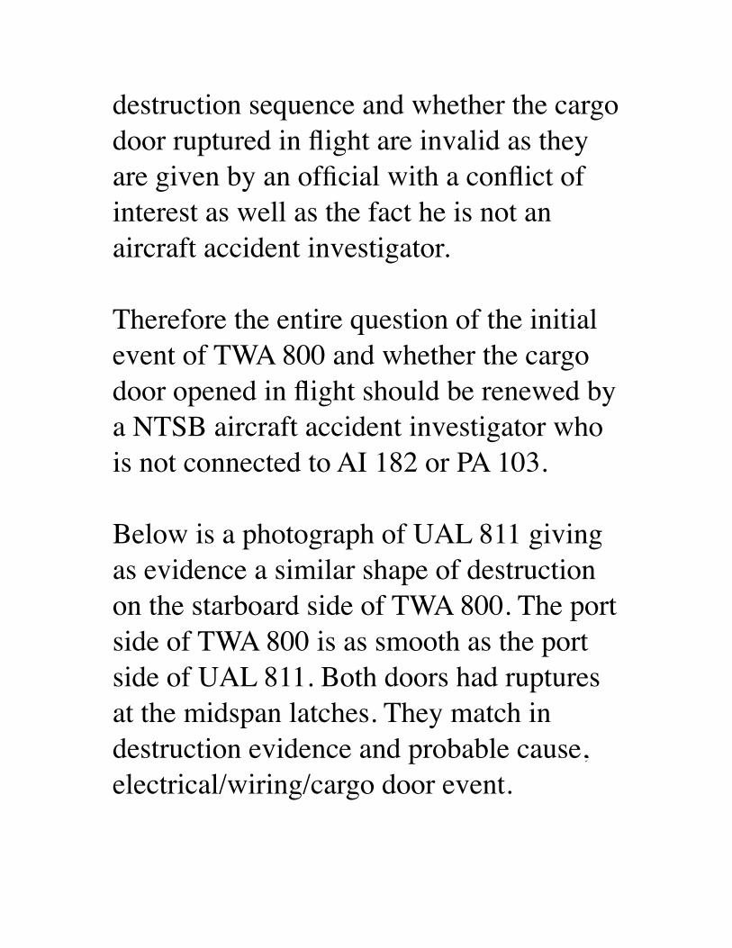
destruction sequence and whether the cargo door ruptured in flight are invalid as they are given by an official with a conflict of interest as well as the fact he is not an aircraft accident investigator.
Therefore the entire question of the initial event of TWA 800 and whether the cargo door opened in flight should be renewed by a NTSB aircraft accident investigator who is not connected to AI 182 or PA 103.
Below is a photograph of UAL 811 giving as evidence a similar shape of destruction on the starboard side of TWA 800. The port side of TWA 800 is as smooth as the port side of UAL 811. Both doors had ruptures at the midspan latches. They match in destruction evidence and probable cause, electrical/wiring/cargo door event.
Sincerely,
John Barry Smith(831) 659-3552 phone551 Country Club Drive,Carmel Valley, CA [email protected] pilot, instrument rated, former FAA Part 135 certificate holder.US Navy reconnaissance navigator, RA-5C 650 hours.US Navy patrol crewman, P2V-5FS 2000 hours.Air Intelligence Officer, US NavyRetired US Army Major MSCOwner Mooney M-20C, 1000 hours.Survivor of sudden night fiery fatal jet plane crash in RA-5CAging, brittle wiring within aircraft poses a
hidden hazard that emerging technologies aim to address
Down to the WireBy Cynthia Furse & Randy Haupt, Utah
State UniversityAs today's military and commercial aircraft
age past their teen years, the many kilometers of wiring buried deep within their structures begin to crack and fray.
Once thought to be rare and benign, such faults are found by the hundreds in a
typical aircraft. Unlike obvious cracks in a wing or an engine, though, damaged wire
is extremely difficult to detect. But the resulting arcing and electromagnetic
emissions can be just as deadly: faulty wiring has been blamed for the downing of Swissair 111 near Nova Scotia in 1998 and of TWA 800 off New York's Long Island in
1996 [see http://www.spectrum.ieee.org/WEBONLY/publicfeature/feb01/
wiref1.html ]. Indeed, any densely wired system is vulnerable--the space shuttle,
nuclear power plants, subways and railroads, even the family car.
Public scrutiny has prompted strongly worded recommendations from the likes of
NASA, the U.S. Federal Aviation Administration, and the National
Transportation Safety Board (NTSB) [see "Government and Industry Take Action" at
http://www.spectrum.ieee.org/WEBONLY/publicfeature/feb01/wiresb1.html ]. "The safety of the nation's wire systems is an
issue of major importance to us all," noted a White House report issued last fall.
Several months earlier, the NTSB concluded its lengthy investigation of TWA
800 with the verdict that a short circuit sparked an explosion in the center wing fuel tank. The condition of the wiring, it
noted, was "not atypical for an airplane of its age." Among the NTSB's
recommendations was to incorporate into aircraft "new technology, such as arc-fault circuit breakers and automated wire test
equipment."Solutions are not straightforward. Among
the most promising technologies are advanced reflectometry methods, for
routine maintenance; so-called smart wire systems, for continual, on-the-spot wire
testing; and arc-fault circuit breakers and advanced fire suppression techniques, for minimizing damage and injury should a
fault occur. Remaining challenges include detecting the minuscule insulation breaks
that encourage arcing; optimizing the benefits and mitigating the risks of the
various wire testing techniques; and getting a better handle on the labyrinthine
complexity of aircraft wiring systems.
Failing the test of timeA healthy wire is perhaps the simplest, yet
most important, element in an electrical system. Typically, a copper conductor
(from 1 to 10 mm in diameter) is covered by a thin outer insulation (from 0.5 to 2
mm thick). Damaged insulation can expose the copper, giving rise to arcs, shorts, and
electromagnetic emission and interference. Arcing occurs when current flows from the
wire through ionized air to another conducting object, such as a second wire or
the aircraft structure. A short circuit channels the current to an undesired
conductor. If an external shield or braid protecting a wire is broken, the resulting antenna radiates the signal on the wire.
As the wire ages, the insulation may become brittle and crack. Vibration can also chafe the insulation as wires vibrate
against each other, a tie-down, or any other
hard surface. Maintenance can also be hard on wires, as they may be nicked by workers' pliers, or bent beyond their
tolerable radius, or sprinkled with metal drill shavings, chemicals or water, or even used as stepladders in hard-to-reach places.
[see Photos at http://www.spectrum.ieee.org/WEBONLY/
publicfeature/feb01/wiref1.html ] that show cracked and singed wiring taken from U.S.
Navy planes.]But perhaps the greatest concern is the
breakdown of the wire's insulation when exposed to moisture. Insulation made from
polyimide film, often referred to by the brand-name Kapton, was once thought to
be the ideal wiring insulation and was widely used in both military and
commercial aircraft during the 1970s and early '80s. A long-chain polymer that is
both tough and durable, with a very high
resistivity, Kapton provides excellent electrical insulation even at a thickness of
less than a millimeter.What was not known initially was how
Kapton held up to the moisture that tends to condense in or near aircraft wiring
harnesses. This moisture is so prevalent that most wires are outfitted with a drip
loop, which prevents water droplets from running down the cables and into critical
electronics. Exposed to this moisture, Kapton's long polymer chains break down,
and the insulation becomes brittle, developing small cracks that in turn let in even more moisture. So-called wet arcs
begin to flow along these cracks, creating intermittent arcs too small to trip normal
circuit breakers and often too small even to interfere with the signal transfer along the
wire. Nonetheless, the tiny arcs do begin to carbonize the insulation, and carbon is an
excellent conductor. Once enough carbon has built up ("enough" depends on the type and thickness of the insulation, the power handling of the wire, and other factors), there can be a large explosive flashover,
with exposed wires spewing molten metal.
One would hope that Kapton cracks are relatively rare. Not so, according to a
recent report by Lectromechanical Design Co., an electrical research firm based in
Sterling, Va. Using a proprietary tool called the DelTest, Letromec engineers tested the wiring in a Boeing 747, an Airbus A300, a
Lockheed L-1011, and two DC-9s that were each over 20 years old and had been retired by commercial airlines within the
previous six months. The results: 13 cracks per 1000 meters of wire in the L-1011,
down to 1.6 cracks per 1000 meters in one of the DC-9s. With approximately 240 km
of wire in the L-1011, this amounted to over 3000 cracks, each a potential cause of
catastrophic arcing.Some time after Kapton's problems came
to light, in the late '70s, its use was cut back, and aircraft manufacturers began replacing it in some of the most critical
wiring systems in planes in service. Alternatives to Kapton include
polyvinylchloride, glass, nylon, polyester, and teflon. But polyimide can still be found
on thousands of aircraft in service, including the McDonnell Douglas MD-11
and older Boeing 737s and 767s.How old is too old?
Updating rather than replacing old planes has become a standard way to save money. Some aircraft being designed today, such as the Joint Strike Fighter, may fly 100 years. Similarly, the B-52s flown by the
U.S. Air Force were built in 1961-62 and
are expected to remain operational until 2045. Its designers would have never
dreamed that this plane would fly for over 80 years. Indeed, not much thought was
given to replacing or inspecting the wiring, because the planes were to have been
retired long before any problems developed.
So when is it time to scrap an airplane because its wires are too old? The answer depends on a complex array of factors--
among them calendar age, manufacturing variations, exposure to water, ultraviolet
light, temperature, vibration and g-forces, and stress during normal use and
maintenance.Planes over 20 years old are virtually
guaranteed to have wiring problems, many of which turn up during routine
maintenance. The average age of civilian aircraft in use today is 18 years, and the
average age of military planes is 16 years. [See table at http://www.spectrum.ieee.org/
WEBONLY/publicfeature/feb01/wiret1.html ] Of course, most fleets are composed of a mix of aircraft types and ages. Trying to relate this information to wiring failure probability rates, such as
those in the table at http://www.spectrum.ieee.org/WEBONLY/
publicfeature/feb01/wiret2.html , gives some idea why wiring problems are
endemic today.Short of replacing an entire aircraft, how about replacing just the wiring system?
That also turns out to be hugely expensive--anywhere from US $1 million
to $5 million for a typical aircraft. Determining what, when, or whether to
replace then means weighing cost against risk--a decision complicated by the fact that neither the cost nor the risk has yet
been fully characterized. What is more, military planes get exposed to more hostile environments than the average commercial
plane, so extrapolation to other types of planes is not necessarily accurate.
The maintenance nightmareSnaking through an aircraft are many kilometers of wire--some 17.5 km in a
Navy F-18C/D fighter, 240 km in a typical wide-body jet. The wire is literally built
into the aircraft, running through fuel tanks, and twisted around hydraulic lines.
Just reaching the wiring harness often entails dismantling an aircraft's external
structure. And merely touching a wire, let alone disconnecting, handling, and
reconnecting it, heightens the risk that the wire will be damaged.
But maintenance workers do not always show due respect. They have been known to stand on wires instead of step stools, to
cut and splice them poorly to get them out of the way of difficult-to-reach places, and
to smack connectors with hammers to loosen them. Tiny razor-sharp metal
shavings from maintenance or upgrades, coupled with ordinary aircraft vibration,
create the perfect conditions for insulation damage.
Other parts of the aircraft never get touched, but are no less problematic. The
dust bunnies and chaff that collect in these out-of-sight areas are excellent tinder to turn sparks into smoke and flames. Then there's the sticky "syrup" that collects in and around wire bundles. This well-aged potion of condensation, toilet and galley leaks, dust, hydraulic fluid, and various
unnamable ingredients is intensely caustic to most kinds of insulation. One of the
Navy and FAA directives for making aging
wiring safer has been simply to improve cleanliness within aircraft!
Compounding the maintenance nightmare is its high cost. By one estimate, the Navy spends 1.8 million person-hours each year
to troubleshoot and repair its aircraft wiring systems.
Why state of the art isn't enoughWire troubleshooting is still very much a
hands-on art that has changed little over the last 40 years. Among the techniques in
current use are visual inspection, several versions of reflectometry, and impedance testing. Each technique has its advantages
and, more importantly, disadvantages.Visual inspection is still the most common way to check for wiring failures. It entails
accessing the cables and then carefully checking the insulation for holes and
cracks, often no larger than the head of a pin. Whole sections of wiring never get
inspected: chafed insulation can be hidden under clamps or around corners, or within
multiwire bundles, each consisting of 75 or more wires. And many wire bundles are built right into the walls of the aircraft.
Another approach involves measuring the cable's resistance from end to end. A low
resistance means the cable is "good," and a high resistance means that it is broken.
When a very high voltage (500 V or more) is placed between adjacent, supposedly
unconnected wires, current leakage from one wire to another can indicate degraded
insulation.There is some concern, though, that high
voltage may in itself damage the insulation. So nondestructive resistance tests, such as those developed by Eclypse International
Corp., Corona, Calif., use voltages of 28 V or less. A floating comparator analyzes the currents on the cable as the input current is
stepped through several levels. In a healthy cable, Ohm's Law predicts that the
resistance will stay the same for all current levels. If it does not, then something is
wrong with the cable. The method has been used to locate cold solder joints, bad crimps, carbonization of the cable or
connectors, and foreign matter on or near the cables. And unlike the high-voltage
tests, it can be used on a fueled airplane. It does, though, still require disconnecting
and reconnecting the cables.Several techniques now used or under
development involve reflectometry. Common to all these methods is the
sending of a signal (a pulse, sine wave, or the like) down the wire and sensing the
reflection that returns from the wire's end. They are most useful for detecting so-
called hard errors, such as short circuits, but have not proven useful for less obvious
wire problems.Time domain reflectometry (TDR) is
customarily used when a wiring problem is already suspected. A short, typically
rectangular pulse is sent down the cable, and the cable impedance, termination, and length give a unique temporal signature to the reflected signal. A trained technician then interprets the signature to determine
the health of the cable. Such signal interpretation is particularly necessary for aircraft systems, where wires branch into
complicated network structures and connect to active avionics. The running
joke about TDR is that it requires a Ph.D. to use.
Standing-wave reflectometry (SWR) involves sending a sinusoidal waveform
down the wire. A reflected sinusoid is returned from the wire's end, and the two signals add to a standing wave on the line.
The peaks and nulls of this standing wave give information on the length and
terminating load of the cable; a healthy line's wave pattern will be distinct from
that of a line with an open or short circuit. The edge this method has over TDR is that
the electronics are simpler and therefore less expensive.
Like SWR, frequency domain reflectometry (FDR) uses sine waves. FDR,
though, directly measures the phase difference between the incident and
reflected waves; any faults in the line will generate resonances between the two
signals. This method is being developed for in situ wire testing by researchers at Utah
State University with support from Management Sciences Inc., Albuquerque,
N.M., and the Naval Air Systems Command. The goal is to allow preflight
testing of cables with the touch of a button, and without the risk of damaging the cables
by disconnecting them.On the horizon
Because of the shortcomings in the above techniques, researchers are now looking at several new technologies. These include
automated reflectometry testing; smart wire systems for real-time, on-the-spot testing;
and, in the event of an in-flight failure, advanced fire suppression methods and arc-
fault circuit breakers.Automating the reflectometry methods now in use may one day mean that maintenance
workers will be able to gauge a cable's health with minimal physical intervention. A hand-held unit would clamp around the wire, rather than directly connecting to it. Recently, a fully automated TDR unit was
developed by Phoenix Aviation and Technology. It provides a wider range of
fault diagnostics and prognostics, with precise location and interpretation of the fault. The same software can be easily embedded into application-specific IC
format or similar small computing platforms, thus paving the way for real-time embedded conductor monitoring.
All the same, reflectometry is pushing the state of the art when it comes to finding small insulation cracks, detecting chafed insulation before arcs occur, and locating an arc's source. Better detection of these
tiny anomalies may be achievable by wetting the cable with water or saline
solution, or filling the plane with inert gas.Perhaps the maintenance worker's greatest nightmare is finding faults that come and
go. These so-called ticking faults arise from vibration, temperature change, moisture, g-forces, electromagnetic
interference, and so on. Diagnosing the
problem requires systems that can function in flight, where ticking faults usually occur.Smart wire systems are thus being designed for testing cables continuously, both before
takeoff and during a flight. Systems now under development include a frequency
domain reflectometer, on-board processor, environmental sensors, and wireless
communication system integrated into a single miniaturized unit, hundreds of which
can be embedded in the wiring system. They will monitor the health of the cable and guide cable maintenance, and even detect any faults that occur and correct
them in real time.For the aircraft being designed today, a
novel kind of wiring with a complete array of embedded sensors is being proposed. This is particularly critical for long-lived planes such as the Joint Strike Fighter.
Weight and space constraints are likely to
drive this technology to nanoscale sensors, emerging material science technologies,
and microelectromechanical system devices.
Of course, wire failures will still occur. New technologies that can help limit the damage in such an event include arc-fault
circuit breakers and fire suppression methods.
--------------------------------------------------------------------------------
Smart wire systems will continuously monitor the cable's health and correct
faults as they occur----------------------------------------------------
----------------------------Ordinary circuit breakers are heat-sensitive
bimetal elements that trip only when a large current passes through the circuit long enough to heat the element. This
power may be on the order of 1000 percent
of the rated current for 0.35 to 0.8 seconds. By comparison, a single arc fault may last only 1.25 ms, and a series of events may
last 20-30 ms. Too fleeting to trip the circuit breaker, these arc faults can
nonetheless cause catastrophic local damage to the wire. Fires have been known
to break out with the breaker still intact.Arc-fault circuit breakers contain
sophisticated electronics to sample the current on the wire at submillisecond
intervals. Both time and frequency domain filtering are used to extract the arc-fault
signature from the current waveform. This signature may be integrated over time to
discriminate, by means of pattern-matching algorithms, between a normal current and a
sputtering arc-fault current. And so ordinary transients, due to, say, a motor
being turned on and off, can be distinguished from the random current
surges that occur with arcing.
Arc-fault breakers are already required in new home wiring in the United States and
are now being miniaturized for use on aircraft. Normally these breakers either are
used in tandem with a traditional heat-sensitive breaker or else include a heat-
sensitive element in addition to the pattern-matching electronics. Ideally, circuitry will also be added to locate the fault after the
breaker has tripped.Once a fire starts on an aircraft, it spreads rapidly, aided by Mylar-backed insulation in the cabin walls, limited access to fire
extinguishers, and so on. New extinguisher designs that rely on super-fine, high-
pressure mists of water, inert gases, and other techniques are now being developed
to put out all types of aircraft fires, including those due to faulty wiring.
Amazingly little is known about how and why wires age, but polymer scientists are
making up for lost time. Among other things, they are studying the chemical and physical changes and resultant effects on
electrical insulation properties that occur as wires age. One goal is to find new
materials to replace copper wiring in signal-transfer and electromagnetic
interference shielding on aircraft, as well as new types of wire insulation that resist
chafing and have extended life and built-in diagnostics.Not to panic
If you happen to read this article while flying, do not panic. Few wiring problems end in disaster. There is cause for concern,
though, as the air fleet continues to age, and our reliance on air transport grows. While an aircraft's other major systems
undergo preflight testing and regular
inspection and maintenance, its central nervous system--wiring--has been long
neglected. Sorely needed are new maintenance methods that account for the
aging of wires, as is done for aging structural and computer systems.
Diagnosis is good. Prognosis is better. And prevention is better still. This last may
require a new way of thinking for electrical engineers, who tend to be more at home with obsolescence than geriatrics. For aging aircraft wiring, diagnostics and
prevention are improving, and prognostics are on the horizon. What remains to be seen is how all of these methods will be
implemented in practical systems, so that disasters like TWA 800 and Swissair 111
can be prevented.Read the Full article (with links and
images) here:http://www.spectrum.ieee.org/WEBONLY/
publicfeature/feb01/wire.htmlhttp://www.iasa.com.au/professor_cynthia_furse.html
From: Mail Delivery Subsystem <[email protected]>Date: February 12, 2001 10:20:08 AM PSTTo: <[email protected]>Subject: Returned mail: see transcript for details
James F. (Jim) Wildey IISenior MetallurgistSequence Group Chairman, TWA flight 800 investigation.National Resource Specialist - Metallurgy
Experience:Employed at the Safety Board in the Materials Laboratory for nearly 25 years, since September, 1975. Chief of the laboratory for 2+ years. Participated in many of the major accidents involving component or structural failures investigated by the Board and foreign countries including 1985 Indian Airlines Boeing 747 bombing, Atlantic Ocean 1988 Aloha Airlines 737 structural failure, Hawaii 1988 Pan Am 103 bombing, Lockerbie, Scotland 1989 United Airlines 747 cargo door failure, Honolulu, Hawaii 1989 United Airlines DC-10 fan disk failure, Sioux City, Iowa 199? DC-10 bombing, Chad, Africa 1996 TWA 800 NTSB Chairman's award, (1989), Recipient of Aviation Week and Space Technology Laurel Award, February 1998, in recognition of the analysis of the breakup of the TWA 800 airplane. Presents a course entitled Fracture Recognition, to students at the NTSB Aircraft Accident Investigation School.
Dear Aviation Public Safety Officials, the one person who has a vested interest in TWA 800 not being a wiring/cargo door event is Mr. Wildey. He is officially connected with AI 182 and PA 103, two events which are officially not wiring/cargo door events but would be if TWA 800 were to become a wiring/cargo door event. This would explain why he is so adamant that TWA 800 was not a cargo door rupture in flight, contrary to photographic and CVR evidence, but a spontaneous center tank explosion which lacks the crucial factor of an identified ignition source: He is protecting his opinions of years past, opinions in hindsight which are now suspect, based on matching evidence in the electrical/cargo door UAL 811 accident.
Mr. Wildey's opinions about the destruction sequence and whether the cargo door ruptured in flight are invalid as they are given by an official with a conflict of interest as well as the fact he is not an aircraft accident investigator.
Therefore the entire question of the initial event of TWA 800 and whether the cargo door opened in flight should be renewed by a NTSB aircraft accident investigator who is not connected to AI 182 or PA 103.
Below is a photograph of UAL 811 giving as evidence a similar shape of destruction on the starboard side of TWA 800. The port side of TWA 800 is as smooth as the port side of UAL 811. Both doors had ruptures at the midspan latches. They match in destruction evidence and probable cause, electrical/wiring/cargo door event.
Sincerely,
John Barry Smith(831) 659-3552 phone551 Country Club Drive,Carmel Valley, CA [email protected] pilot, instrument rated, former FAA Part 135 certificate holder.US Navy reconnaissance navigator, RA-5C 650 hours.US Navy patrol crewman, P2V-5FS 2000 hours.Air Intelligence Officer, US NavyRetired US Army Major MSCOwner Mooney M-20C, 1000 hours.Survivor of sudden night fiery fatal jet plane crash in RA-5C
Aging, brittle wiring within aircraft poses a hidden hazard that emerging technologies aim to address
Down to the WireBy Cynthia Furse & Randy Haupt, Utah State University
As today's military and commercial aircraft age past their teen years, the many kilometers of wiring buried deep within their structures begin to crack and fray. Once thought to be rare and
benign, such faults are found by the hundreds in a typical aircraft. Unlike obvious cracks in a wing or an engine, though, damaged wire is extremely difficult to detect. But the resulting
arcing and electromagnetic emissions can be just as deadly: faulty wiring has been blamed for the downing of Swissair 111
near Nova Scotia in 1998 and of TWA 800 off New York's Long Island in 1996 [see http://www.spectrum.ieee.org/WEBONLY/publicfeature/feb01/wiref1.html ]. Indeed, any densely wired system is vulnerable--the space shuttle, nuclear power plants,
subways and railroads, even the family car.
Public scrutiny has prompted strongly worded recommendations from the likes of NASA, the U.S. Federal Aviation
Administration, and the National Transportation Safety Board (NTSB) [see "Government and Industry Take Action" at http://
www.spectrum.ieee.org/WEBONLY/publicfeature/feb01/wiresb1.html ]. "The safety of the nation's wire systems is an
issue of major importance to us all," noted a White House report issued last fall. Several months earlier, the NTSB concluded its lengthy investigation of TWA 800 with the verdict that a short circuit sparked an explosion in the center wing fuel tank. The
condition of the wiring, it noted, was "not atypical for an airplane of its age." Among the NTSB's recommendations was to
incorporate into aircraft "new technology, such as arc-fault circuit breakers and automated wire test equipment."
Solutions are not straightforward. Among the most promising technologies are advanced reflectometry methods, for routine
maintenance; so-called smart wire systems, for continual, on-the-spot wire testing; and arc-fault circuit breakers and advanced fire
suppression techniques, for minimizing damage and injury should a fault occur. Remaining challenges include detecting the minuscule insulation breaks that encourage arcing; optimizing the benefits and mitigating the risks of the various wire testing
techniques; and getting a better handle on the labyrinthine complexity of aircraft wiring systems.
Failing the test of timeA healthy wire is perhaps the simplest, yet most important,
element in an electrical system. Typically, a copper conductor (from 1 to 10 mm in diameter) is covered by a thin outer
insulation (from 0.5 to 2 mm thick). Damaged insulation can expose the copper, giving rise to arcs, shorts, and
electromagnetic emission and interference. Arcing occurs when current flows from the wire through ionized air to another
conducting object, such as a second wire or the aircraft structure. A short circuit channels the current to an undesired conductor. If
an external shield or braid protecting a wire is broken, the resulting antenna radiates the signal on the wire.
As the wire ages, the insulation may become brittle and crack. Vibration can also chafe the insulation as wires vibrate against each other, a tie-down, or any other hard surface. Maintenance can also be hard on wires, as they may be nicked by workers' pliers, or bent beyond their tolerable radius, or sprinkled with
metal drill shavings, chemicals or water, or even used as stepladders in hard-to-reach places. [see Photos at http://www.spectrum.ieee.org/WEBONLY/publicfeature/feb01/
wiref1.html ] that show cracked and singed wiring taken from U.S. Navy planes.]
But perhaps the greatest concern is the breakdown of the wire's insulation when exposed to moisture. Insulation made from
polyimide film, often referred to by the brand-name Kapton, was once thought to be the ideal wiring insulation and was widely used in both military and commercial aircraft during the 1970s
and early '80s. A long-chain polymer that is both tough and durable, with a very high resistivity, Kapton provides excellent
electrical insulation even at a thickness of less than a millimeter.What was not known initially was how Kapton held up to the
moisture that tends to condense in or near aircraft wiring harnesses. This moisture is so prevalent that most wires are
outfitted with a drip loop, which prevents water droplets from running down the cables and into critical electronics. Exposed to this moisture, Kapton's long polymer chains break down, and the insulation becomes brittle, developing small cracks that in turn
let in even more moisture. So-called wet arcs begin to flow along these cracks, creating intermittent arcs too small to trip normal circuit breakers and often too small even to interfere with the
signal transfer along the wire. Nonetheless, the tiny arcs do begin
to carbonize the insulation, and carbon is an excellent conductor. Once enough carbon has built up ("enough" depends on the type and thickness of the insulation, the power handling of the wire, and other factors), there can be a large explosive flashover, with
exposed wires spewing molten metal.
One would hope that Kapton cracks are relatively rare. Not so, according to a recent report by Lectromechanical Design Co., an electrical research firm based in Sterling, Va. Using a proprietary tool called the DelTest, Letromec engineers tested the wiring in a
Boeing 747, an Airbus A300, a Lockheed L-1011, and two DC-9s that were each over 20 years old and had been retired by commercial airlines within the previous six months. The results:
13 cracks per 1000 meters of wire in the L-1011, down to 1.6 cracks per 1000 meters in one of the DC-9s. With approximately
240 km of wire in the L-1011, this amounted to over 3000 cracks, each a potential cause of catastrophic arcing.
Some time after Kapton's problems came to light, in the late '70s, its use was cut back, and aircraft manufacturers began replacing
it in some of the most critical wiring systems in planes in service. Alternatives to Kapton include polyvinylchloride, glass, nylon,
polyester, and teflon. But polyimide can still be found on thousands of aircraft in service, including the McDonnell
Douglas MD-11 and older Boeing 737s and 767s.How old is too old?
Updating rather than replacing old planes has become a standard way to save money. Some aircraft being designed today, such as the Joint Strike Fighter, may fly 100 years. Similarly, the B-52s
flown by the U.S. Air Force were built in 1961-62 and are expected to remain operational until 2045. Its designers would have never dreamed that this plane would fly for over 80 years. Indeed, not much thought was given to replacing or inspecting the wiring, because the planes were to have been retired long
before any problems developed.So when is it time to scrap an airplane because its wires are too old? The answer depends on a complex array of factors--among them calendar age, manufacturing variations, exposure to water, ultraviolet light, temperature, vibration and g-forces, and stress
during normal use and maintenance.Planes over 20 years old are virtually guaranteed to have wiring problems, many of which turn up during routine maintenance.
The average age of civilian aircraft in use today is 18 years, and the average age of military planes is 16 years. [See table at http://
www.spectrum.ieee.org/WEBONLY/publicfeature/feb01/wiret1.html ] Of course, most fleets are composed of a mix of
aircraft types and ages. Trying to relate this information to wiring failure probability rates, such as those in the table at http://www.spectrum.ieee.org/WEBONLY/publicfeature/feb01/
wiret2.html , gives some idea why wiring problems are endemic today.
Short of replacing an entire aircraft, how about replacing just the wiring system? That also turns out to be hugely expensive--
anywhere from US $1 million to $5 million for a typical aircraft. Determining what, when, or whether to replace then means
weighing cost against risk--a decision complicated by the fact that neither the cost nor the risk has yet been fully characterized.
What is more, military planes get exposed to more hostile environments than the average commercial plane, so
extrapolation to other types of planes is not necessarily accurate.The maintenance nightmare
Snaking through an aircraft are many kilometers of wire--some 17.5 km in a Navy F-18C/D fighter, 240 km in a typical wide-
body jet. The wire is literally built into the aircraft, running through fuel tanks, and twisted around hydraulic lines. Just
reaching the wiring harness often entails dismantling an aircraft's external structure. And merely touching a wire, let alone
disconnecting, handling, and reconnecting it, heightens the risk that the wire will be damaged.
But maintenance workers do not always show due respect. They have been known to stand on wires instead of step stools, to cut and splice them poorly to get them out of the way of difficult-to-reach places, and to smack connectors with hammers to loosen
them. Tiny razor-sharp metal shavings from maintenance or upgrades, coupled with ordinary aircraft vibration, create the
perfect conditions for insulation damage.
Other parts of the aircraft never get touched, but are no less problematic. The dust bunnies and chaff that collect in these out-of-sight areas are excellent tinder to turn sparks into smoke and
flames. Then there's the sticky "syrup" that collects in and around wire bundles. This well-aged potion of condensation, toilet and
galley leaks, dust, hydraulic fluid, and various unnamable ingredients is intensely caustic to most kinds of insulation. One of the Navy and FAA directives for making aging wiring safer
has been simply to improve cleanliness within aircraft!Compounding the maintenance nightmare is its high cost. By one estimate, the Navy spends 1.8 million person-hours each year to
troubleshoot and repair its aircraft wiring systems.Why state of the art isn't enough
Wire troubleshooting is still very much a hands-on art that has changed little over the last 40 years. Among the techniques in
current use are visual inspection, several versions of reflectometry, and impedance testing. Each technique has its
advantages and, more importantly, disadvantages.Visual inspection is still the most common way to check for
wiring failures. It entails accessing the cables and then carefully checking the insulation for holes and cracks, often no larger than the head of a pin. Whole sections of wiring never get inspected: chafed insulation can be hidden under clamps or around corners,
or within multiwire bundles, each consisting of 75 or more wires. And many wire bundles are built right into the walls of the
aircraft.Another approach involves measuring the cable's resistance from
end to end. A low resistance means the cable is "good," and a high resistance means that it is broken. When a very high voltage
(500 V or more) is placed between adjacent, supposedly unconnected wires, current leakage from one wire to another can
indicate degraded insulation.There is some concern, though, that high voltage may in itself
damage the insulation. So nondestructive resistance tests, such as those developed by Eclypse International Corp., Corona, Calif., use voltages of 28 V or less. A floating comparator analyzes the
currents on the cable as the input current is stepped through several levels. In a healthy cable, Ohm's Law predicts that the
resistance will stay the same for all current levels. If it does not, then something is wrong with the cable. The method has been
used to locate cold solder joints, bad crimps, carbonization of the cable or connectors, and foreign matter on or near the cables. And unlike the high-voltage tests, it can be used on a fueled
airplane. It does, though, still require disconnecting and reconnecting the cables.
Several techniques now used or under development involve reflectometry. Common to all these methods is the sending of a
signal (a pulse, sine wave, or the like) down the wire and sensing the reflection that returns from the wire's end. They are most
useful for detecting so-called hard errors, such as short circuits, but have not proven useful for less obvious wire problems.
Time domain reflectometry (TDR) is customarily used when a wiring problem is already suspected. A short, typically rectangular pulse is sent down the cable, and the cable
impedance, termination, and length give a unique temporal signature to the reflected signal. A trained technician then
interprets the signature to determine the health of the cable. Such signal interpretation is particularly necessary for aircraft systems,
where wires branch into complicated network structures and connect to active avionics. The running joke about TDR is that it
requires a Ph.D. to use.Standing-wave reflectometry (SWR) involves sending a
sinusoidal waveform down the wire. A reflected sinusoid is returned from the wire's end, and the two signals add to a
standing wave on the line. The peaks and nulls of this standing wave give information on the length and terminating load of the cable; a healthy line's wave pattern will be distinct from that of a line with an open or short circuit. The edge this method has over
TDR is that the electronics are simpler and therefore less expensive.
Like SWR, frequency domain reflectometry (FDR) uses sine waves. FDR, though, directly measures the phase difference
between the incident and reflected waves; any faults in the line will generate resonances between the two signals. This method is
being developed for in situ wire testing by researchers at Utah State University with support from Management Sciences Inc., Albuquerque, N.M., and the Naval Air Systems Command. The
goal is to allow preflight testing of cables with the touch of a button, and without the risk of damaging the cables by
disconnecting them.On the horizon
Because of the shortcomings in the above techniques, researchers are now looking at several new technologies. These include
automated reflectometry testing; smart wire systems for real-time, on-the-spot testing; and, in the event of an in-flight failure, advanced fire suppression methods and arc-fault circuit breakers.Automating the reflectometry methods now in use may one day mean that maintenance workers will be able to gauge a cable's
health with minimal physical intervention. A hand-held unit would clamp around the wire, rather than directly connecting to
it. Recently, a fully automated TDR unit was developed by Phoenix Aviation and Technology. It provides a wider range of
fault diagnostics and prognostics, with precise location and interpretation of the fault. The same software can be easily
embedded into application-specific IC format or similar small computing platforms, thus paving the way for real-time
embedded conductor monitoring.All the same, reflectometry is pushing the state of the art when it
comes to finding small insulation cracks, detecting chafed insulation before arcs occur, and locating an arc's source. Better detection of these tiny anomalies may be achievable by wetting the cable with water or saline solution, or filling the plane with
inert gas.Perhaps the maintenance worker's greatest nightmare is finding
faults that come and go. These so-called ticking faults arise from vibration, temperature change, moisture, g-forces,
electromagnetic interference, and so on. Diagnosing the problem requires systems that can function in flight, where ticking faults
usually occur.Smart wire systems are thus being designed for testing cables continuously, both before takeoff and during a flight. Systems
now under development include a frequency domain reflectometer, on-board processor, environmental sensors, and
wireless communication system integrated into a single miniaturized unit, hundreds of which can be embedded in the wiring system. They will monitor the health of the cable and
guide cable maintenance, and even detect any faults that occur and correct them in real time.
For the aircraft being designed today, a novel kind of wiring with a complete array of embedded sensors is being proposed. This is particularly critical for long-lived planes such as the Joint Strike
Fighter. Weight and space constraints are likely to drive this technology to nanoscale sensors, emerging material science technologies, and microelectromechanical system devices.
Of course, wire failures will still occur. New technologies that can help limit the damage in such an event include arc-fault
circuit breakers and fire suppression methods.------------------------------------------------------------------------------
--Smart wire systems will continuously monitor the cable's
health and correct faults as they occur------------------------------------------------------------------------------
--Ordinary circuit breakers are heat-sensitive bimetal elements that
trip only when a large current passes through the circuit long enough to heat the element. This power may be on the order of
1000 percent of the rated current for 0.35 to 0.8 seconds. By comparison, a single arc fault may last only 1.25 ms, and a series
of events may last 20-30 ms. Too fleeting to trip the circuit breaker, these arc faults can nonetheless cause catastrophic local damage to the wire. Fires have been known to break out with the
breaker still intact.Arc-fault circuit breakers contain sophisticated electronics to
sample the current on the wire at submillisecond intervals. Both time and frequency domain filtering are used to extract the arc-
fault signature from the current waveform. This signature may be integrated over time to discriminate, by means of pattern-
matching algorithms, between a normal current and a sputtering arc-fault current. And so ordinary transients, due to, say, a motor being turned on and off, can be distinguished from the random
current surges that occur with arcing.
Arc-fault breakers are already required in new home wiring in the United States and are now being miniaturized for use on
aircraft. Normally these breakers either are used in tandem with a traditional heat-sensitive breaker or else include a heat-sensitive element in addition to the pattern-matching electronics. Ideally, circuitry will also be added to locate the fault after the breaker
has tripped.Once a fire starts on an aircraft, it spreads rapidly, aided by
Mylar-backed insulation in the cabin walls, limited access to fire extinguishers, and so on. New extinguisher designs that rely on super-fine, high-pressure mists of water, inert gases, and other
techniques are now being developed to put out all types of aircraft fires, including those due to faulty wiring.
Amazingly little is known about how and why wires age, but polymer scientists are making up for lost time. Among other
things, they are studying the chemical and physical changes and resultant effects on electrical insulation properties that occur as wires age. One goal is to find new materials to replace copper
wiring in signal-transfer and electromagnetic interference shielding on aircraft, as well as new types of wire insulation that
resist chafing and have extended life and built-in diagnostics.Not to panic
If you happen to read this article while flying, do not panic. Few wiring problems end in disaster. There is cause for concern,
though, as the air fleet continues to age, and our reliance on air transport grows. While an aircraft's other major systems undergo
preflight testing and regular inspection and maintenance, its central nervous system--wiring--has been long neglected. Sorely needed are new maintenance methods that account for the aging of wires, as is done for aging structural and computer systems.Diagnosis is good. Prognosis is better. And prevention is better still. This last may require a new way of thinking for electrical
engineers, who tend to be more at home with obsolescence than geriatrics. For aging aircraft wiring, diagnostics and prevention
are improving, and prognostics are on the horizon. What remains
to be seen is how all of these methods will be implemented in practical systems, so that disasters like TWA 800 and Swissair
111 can be prevented.Read the Full article (with links and images) here:
http://www.spectrum.ieee.org/WEBONLY/publicfeature/feb01/wire.html
http://www.iasa.com.au/professor_cynthia_furse.html
From: Mail Delivery Subsystem <[email protected]>Date: February 12, 2001 10:20:39 AM PSTTo: <[email protected]>Subject: Returned mail: see transcript for details
James F. (Jim) Wildey IISenior MetallurgistSequence Group Chairman, TWA flight 800 investigation.National Resource Specialist - Metallurgy
Experience:Employed at the Safety Board in the Materials Laboratory for nearly 25 years, since September, 1975. Chief of the laboratory for 2+ years. Participated in many of the major accidents involving component or structural failures investigated by the Board and foreign countries including 1985 Indian Airlines Boeing 747 bombing, Atlantic Ocean 1988 Aloha Airlines 737 structural failure, Hawaii 1988 Pan Am 103 bombing, Lockerbie, Scotland 1989 United Airlines 747 cargo door failure, Honolulu, Hawaii 1989 United Airlines DC-10 fan disk failure, Sioux City, Iowa 199? DC-10 bombing, Chad, Africa 1996 TWA 800 NTSB Chairman's award, (1989), Recipient of Aviation Week and Space Technology Laurel Award, February 1998, in recognition of the analysis of the breakup of the TWA 800 airplane. Presents a
course entitled Fracture Recognition, to students at the NTSB Aircraft Accident Investigation School.
Dear Aviation Public Safety Officials, the one person who has a vested interest in TWA 800 not being a wiring/cargo door event is Mr. Wildey. He is officially connected with AI 182 and PA 103, two events which are officially not wiring/cargo door events but would be if TWA 800 were to become a wiring/cargo door event. This would explain why he is so adamant that TWA 800 was not a cargo door rupture in flight, contrary to photographic and CVR evidence, but a spontaneous center tank explosion which lacks the crucial factor of an identified ignition source: He is protecting his opinions of years past, opinions in hindsight which are now suspect, based on matching evidence in the electrical/cargo door UAL 811 accident.
Mr. Wildey's opinions about the destruction sequence and whether the cargo door ruptured in flight are invalid as they are given by an official with a conflict of interest as well as the fact he is not an aircraft accident investigator.
Therefore the entire question of the initial event of TWA 800 and whether the cargo door opened in flight should be renewed by a NTSB aircraft accident investigator who is not connected to AI 182 or PA 103.
Below is a photograph of UAL 811 giving as evidence a similar shape of destruction on the starboard side of TWA 800. The port side of TWA 800 is as smooth as the port side of UAL 811. Both doors had ruptures at the midspan latches. They match in destruction evidence and probable cause, electrical/wiring/cargo door event.
Sincerely,
John Barry Smith(831) 659-3552 phone551 Country Club Drive,Carmel Valley, CA [email protected] pilot, instrument rated, former FAA Part 135 certificate holder.US Navy reconnaissance navigator, RA-5C 650 hours.US Navy patrol crewman, P2V-5FS 2000 hours.Air Intelligence Officer, US NavyRetired US Army Major MSCOwner Mooney M-20C, 1000 hours.Survivor of sudden night fiery fatal jet plane crash in RA-5C
Aging, brittle wiring within aircraft poses a hidden hazard that emerging technologies aim to address
Down to the WireBy Cynthia Furse & Randy Haupt, Utah State University
As today's military and commercial aircraft age past their teen years, the many kilometers of wiring buried deep within their structures begin to crack and fray. Once thought to be rare and
benign, such faults are found by the hundreds in a typical aircraft. Unlike obvious cracks in a wing or an engine, though, damaged wire is extremely difficult to detect. But the resulting
arcing and electromagnetic emissions can be just as deadly: faulty wiring has been blamed for the downing of Swissair 111
near Nova Scotia in 1998 and of TWA 800 off New York's Long Island in 1996 [see http://www.spectrum.ieee.org/WEBONLY/publicfeature/feb01/wiref1.html ]. Indeed, any densely wired
system is vulnerable--the space shuttle, nuclear power plants, subways and railroads, even the family car.
Public scrutiny has prompted strongly worded recommendations from the likes of NASA, the U.S. Federal Aviation
Administration, and the National Transportation Safety Board (NTSB) [see "Government and Industry Take Action" at http://
www.spectrum.ieee.org/WEBONLY/publicfeature/feb01/wiresb1.html ]. "The safety of the nation's wire systems is an
issue of major importance to us all," noted a White House report issued last fall. Several months earlier, the NTSB concluded its lengthy investigation of TWA 800 with the verdict that a short circuit sparked an explosion in the center wing fuel tank. The
condition of the wiring, it noted, was "not atypical for an airplane of its age." Among the NTSB's recommendations was to
incorporate into aircraft "new technology, such as arc-fault circuit breakers and automated wire test equipment."
Solutions are not straightforward. Among the most promising technologies are advanced reflectometry methods, for routine
maintenance; so-called smart wire systems, for continual, on-the-spot wire testing; and arc-fault circuit breakers and advanced fire
suppression techniques, for minimizing damage and injury should a fault occur. Remaining challenges include detecting the minuscule insulation breaks that encourage arcing; optimizing the benefits and mitigating the risks of the various wire testing
techniques; and getting a better handle on the labyrinthine complexity of aircraft wiring systems.
Failing the test of timeA healthy wire is perhaps the simplest, yet most important,
element in an electrical system. Typically, a copper conductor (from 1 to 10 mm in diameter) is covered by a thin outer
insulation (from 0.5 to 2 mm thick). Damaged insulation can expose the copper, giving rise to arcs, shorts, and
electromagnetic emission and interference. Arcing occurs when current flows from the wire through ionized air to another
conducting object, such as a second wire or the aircraft structure. A short circuit channels the current to an undesired conductor. If
an external shield or braid protecting a wire is broken, the resulting antenna radiates the signal on the wire.
As the wire ages, the insulation may become brittle and crack. Vibration can also chafe the insulation as wires vibrate against each other, a tie-down, or any other hard surface. Maintenance can also be hard on wires, as they may be nicked by workers' pliers, or bent beyond their tolerable radius, or sprinkled with
metal drill shavings, chemicals or water, or even used as stepladders in hard-to-reach places. [see Photos at http://www.spectrum.ieee.org/WEBONLY/publicfeature/feb01/
wiref1.html ] that show cracked and singed wiring taken from U.S. Navy planes.]
But perhaps the greatest concern is the breakdown of the wire's insulation when exposed to moisture. Insulation made from
polyimide film, often referred to by the brand-name Kapton, was once thought to be the ideal wiring insulation and was widely used in both military and commercial aircraft during the 1970s
and early '80s. A long-chain polymer that is both tough and durable, with a very high resistivity, Kapton provides excellent
electrical insulation even at a thickness of less than a millimeter.What was not known initially was how Kapton held up to the
moisture that tends to condense in or near aircraft wiring harnesses. This moisture is so prevalent that most wires are
outfitted with a drip loop, which prevents water droplets from running down the cables and into critical electronics. Exposed to this moisture, Kapton's long polymer chains break down, and the insulation becomes brittle, developing small cracks that in turn
let in even more moisture. So-called wet arcs begin to flow along these cracks, creating intermittent arcs too small to trip normal
circuit breakers and often too small even to interfere with the signal transfer along the wire. Nonetheless, the tiny arcs do begin to carbonize the insulation, and carbon is an excellent conductor. Once enough carbon has built up ("enough" depends on the type and thickness of the insulation, the power handling of the wire, and other factors), there can be a large explosive flashover, with
exposed wires spewing molten metal.
One would hope that Kapton cracks are relatively rare. Not so, according to a recent report by Lectromechanical Design Co., an electrical research firm based in Sterling, Va. Using a proprietary tool called the DelTest, Letromec engineers tested the wiring in a
Boeing 747, an Airbus A300, a Lockheed L-1011, and two DC-9s that were each over 20 years old and had been retired by commercial airlines within the previous six months. The results:
13 cracks per 1000 meters of wire in the L-1011, down to 1.6 cracks per 1000 meters in one of the DC-9s. With approximately
240 km of wire in the L-1011, this amounted to over 3000 cracks, each a potential cause of catastrophic arcing.
Some time after Kapton's problems came to light, in the late '70s, its use was cut back, and aircraft manufacturers began replacing
it in some of the most critical wiring systems in planes in service. Alternatives to Kapton include polyvinylchloride, glass, nylon,
polyester, and teflon. But polyimide can still be found on thousands of aircraft in service, including the McDonnell
Douglas MD-11 and older Boeing 737s and 767s.How old is too old?
Updating rather than replacing old planes has become a standard way to save money. Some aircraft being designed today, such as the Joint Strike Fighter, may fly 100 years. Similarly, the B-52s
flown by the U.S. Air Force were built in 1961-62 and are expected to remain operational until 2045. Its designers would have never dreamed that this plane would fly for over 80 years.
Indeed, not much thought was given to replacing or inspecting the wiring, because the planes were to have been retired long
before any problems developed.So when is it time to scrap an airplane because its wires are too old? The answer depends on a complex array of factors--among them calendar age, manufacturing variations, exposure to water, ultraviolet light, temperature, vibration and g-forces, and stress
during normal use and maintenance.Planes over 20 years old are virtually guaranteed to have wiring problems, many of which turn up during routine maintenance.
The average age of civilian aircraft in use today is 18 years, and the average age of military planes is 16 years. [See table at http://
www.spectrum.ieee.org/WEBONLY/publicfeature/feb01/wiret1.html ] Of course, most fleets are composed of a mix of
aircraft types and ages. Trying to relate this information to wiring failure probability rates, such as those in the table at http://www.spectrum.ieee.org/WEBONLY/publicfeature/feb01/
wiret2.html , gives some idea why wiring problems are endemic today.
Short of replacing an entire aircraft, how about replacing just the wiring system? That also turns out to be hugely expensive--
anywhere from US $1 million to $5 million for a typical aircraft. Determining what, when, or whether to replace then means
weighing cost against risk--a decision complicated by the fact that neither the cost nor the risk has yet been fully characterized.
What is more, military planes get exposed to more hostile environments than the average commercial plane, so
extrapolation to other types of planes is not necessarily accurate.The maintenance nightmare
Snaking through an aircraft are many kilometers of wire--some 17.5 km in a Navy F-18C/D fighter, 240 km in a typical wide-
body jet. The wire is literally built into the aircraft, running through fuel tanks, and twisted around hydraulic lines. Just
reaching the wiring harness often entails dismantling an aircraft's external structure. And merely touching a wire, let alone
disconnecting, handling, and reconnecting it, heightens the risk that the wire will be damaged.
But maintenance workers do not always show due respect. They have been known to stand on wires instead of step stools, to cut and splice them poorly to get them out of the way of difficult-to-reach places, and to smack connectors with hammers to loosen
them. Tiny razor-sharp metal shavings from maintenance or upgrades, coupled with ordinary aircraft vibration, create the
perfect conditions for insulation damage.
Other parts of the aircraft never get touched, but are no less problematic. The dust bunnies and chaff that collect in these out-of-sight areas are excellent tinder to turn sparks into smoke and
flames. Then there's the sticky "syrup" that collects in and around wire bundles. This well-aged potion of condensation, toilet and
galley leaks, dust, hydraulic fluid, and various unnamable ingredients is intensely caustic to most kinds of insulation. One of the Navy and FAA directives for making aging wiring safer
has been simply to improve cleanliness within aircraft!Compounding the maintenance nightmare is its high cost. By one estimate, the Navy spends 1.8 million person-hours each year to
troubleshoot and repair its aircraft wiring systems.Why state of the art isn't enough
Wire troubleshooting is still very much a hands-on art that has changed little over the last 40 years. Among the techniques in
current use are visual inspection, several versions of reflectometry, and impedance testing. Each technique has its
advantages and, more importantly, disadvantages.Visual inspection is still the most common way to check for
wiring failures. It entails accessing the cables and then carefully checking the insulation for holes and cracks, often no larger than
the head of a pin. Whole sections of wiring never get inspected: chafed insulation can be hidden under clamps or around corners, or within multiwire bundles, each consisting of 75 or more wires.
And many wire bundles are built right into the walls of the aircraft.
Another approach involves measuring the cable's resistance from end to end. A low resistance means the cable is "good," and a
high resistance means that it is broken. When a very high voltage (500 V or more) is placed between adjacent, supposedly
unconnected wires, current leakage from one wire to another can indicate degraded insulation.
There is some concern, though, that high voltage may in itself damage the insulation. So nondestructive resistance tests, such as those developed by Eclypse International Corp., Corona, Calif., use voltages of 28 V or less. A floating comparator analyzes the
currents on the cable as the input current is stepped through several levels. In a healthy cable, Ohm's Law predicts that the
resistance will stay the same for all current levels. If it does not, then something is wrong with the cable. The method has been
used to locate cold solder joints, bad crimps, carbonization of the cable or connectors, and foreign matter on or near the cables. And unlike the high-voltage tests, it can be used on a fueled
airplane. It does, though, still require disconnecting and reconnecting the cables.
Several techniques now used or under development involve reflectometry. Common to all these methods is the sending of a
signal (a pulse, sine wave, or the like) down the wire and sensing the reflection that returns from the wire's end. They are most
useful for detecting so-called hard errors, such as short circuits, but have not proven useful for less obvious wire problems.
Time domain reflectometry (TDR) is customarily used when a wiring problem is already suspected. A short, typically rectangular pulse is sent down the cable, and the cable
impedance, termination, and length give a unique temporal signature to the reflected signal. A trained technician then
interprets the signature to determine the health of the cable. Such signal interpretation is particularly necessary for aircraft systems,
where wires branch into complicated network structures and connect to active avionics. The running joke about TDR is that it
requires a Ph.D. to use.Standing-wave reflectometry (SWR) involves sending a
sinusoidal waveform down the wire. A reflected sinusoid is returned from the wire's end, and the two signals add to a
standing wave on the line. The peaks and nulls of this standing wave give information on the length and terminating load of the cable; a healthy line's wave pattern will be distinct from that of a line with an open or short circuit. The edge this method has over
TDR is that the electronics are simpler and therefore less expensive.
Like SWR, frequency domain reflectometry (FDR) uses sine waves. FDR, though, directly measures the phase difference
between the incident and reflected waves; any faults in the line will generate resonances between the two signals. This method is
being developed for in situ wire testing by researchers at Utah State University with support from Management Sciences Inc., Albuquerque, N.M., and the Naval Air Systems Command. The
goal is to allow preflight testing of cables with the touch of a button, and without the risk of damaging the cables by
disconnecting them.On the horizon
Because of the shortcomings in the above techniques, researchers are now looking at several new technologies. These include
automated reflectometry testing; smart wire systems for real-time, on-the-spot testing; and, in the event of an in-flight failure, advanced fire suppression methods and arc-fault circuit breakers.
Automating the reflectometry methods now in use may one day mean that maintenance workers will be able to gauge a cable's
health with minimal physical intervention. A hand-held unit would clamp around the wire, rather than directly connecting to
it. Recently, a fully automated TDR unit was developed by Phoenix Aviation and Technology. It provides a wider range of
fault diagnostics and prognostics, with precise location and interpretation of the fault. The same software can be easily
embedded into application-specific IC format or similar small computing platforms, thus paving the way for real-time
embedded conductor monitoring.All the same, reflectometry is pushing the state of the art when it
comes to finding small insulation cracks, detecting chafed insulation before arcs occur, and locating an arc's source. Better detection of these tiny anomalies may be achievable by wetting the cable with water or saline solution, or filling the plane with
inert gas.Perhaps the maintenance worker's greatest nightmare is finding
faults that come and go. These so-called ticking faults arise from vibration, temperature change, moisture, g-forces,
electromagnetic interference, and so on. Diagnosing the problem requires systems that can function in flight, where ticking faults
usually occur.Smart wire systems are thus being designed for testing cables continuously, both before takeoff and during a flight. Systems
now under development include a frequency domain reflectometer, on-board processor, environmental sensors, and
wireless communication system integrated into a single miniaturized unit, hundreds of which can be embedded in the wiring system. They will monitor the health of the cable and
guide cable maintenance, and even detect any faults that occur and correct them in real time.
For the aircraft being designed today, a novel kind of wiring with
a complete array of embedded sensors is being proposed. This is particularly critical for long-lived planes such as the Joint Strike
Fighter. Weight and space constraints are likely to drive this technology to nanoscale sensors, emerging material science technologies, and microelectromechanical system devices.
Of course, wire failures will still occur. New technologies that can help limit the damage in such an event include arc-fault
circuit breakers and fire suppression methods.------------------------------------------------------------------------------
--Smart wire systems will continuously monitor the cable's
health and correct faults as they occur------------------------------------------------------------------------------
--Ordinary circuit breakers are heat-sensitive bimetal elements that
trip only when a large current passes through the circuit long enough to heat the element. This power may be on the order of
1000 percent of the rated current for 0.35 to 0.8 seconds. By comparison, a single arc fault may last only 1.25 ms, and a series
of events may last 20-30 ms. Too fleeting to trip the circuit breaker, these arc faults can nonetheless cause catastrophic local damage to the wire. Fires have been known to break out with the
breaker still intact.Arc-fault circuit breakers contain sophisticated electronics to
sample the current on the wire at submillisecond intervals. Both time and frequency domain filtering are used to extract the arc-
fault signature from the current waveform. This signature may be integrated over time to discriminate, by means of pattern-
matching algorithms, between a normal current and a sputtering arc-fault current. And so ordinary transients, due to, say, a motor being turned on and off, can be distinguished from the random
current surges that occur with arcing.
Arc-fault breakers are already required in new home wiring in the United States and are now being miniaturized for use on
aircraft. Normally these breakers either are used in tandem with a traditional heat-sensitive breaker or else include a heat-sensitive element in addition to the pattern-matching electronics. Ideally, circuitry will also be added to locate the fault after the breaker
has tripped.Once a fire starts on an aircraft, it spreads rapidly, aided by
Mylar-backed insulation in the cabin walls, limited access to fire extinguishers, and so on. New extinguisher designs that rely on super-fine, high-pressure mists of water, inert gases, and other
techniques are now being developed to put out all types of aircraft fires, including those due to faulty wiring.
Amazingly little is known about how and why wires age, but polymer scientists are making up for lost time. Among other
things, they are studying the chemical and physical changes and resultant effects on electrical insulation properties that occur as wires age. One goal is to find new materials to replace copper
wiring in signal-transfer and electromagnetic interference shielding on aircraft, as well as new types of wire insulation that
resist chafing and have extended life and built-in diagnostics.Not to panic
If you happen to read this article while flying, do not panic. Few wiring problems end in disaster. There is cause for concern,
though, as the air fleet continues to age, and our reliance on air transport grows. While an aircraft's other major systems undergo
preflight testing and regular inspection and maintenance, its central nervous system--wiring--has been long neglected. Sorely needed are new maintenance methods that account for the aging of wires, as is done for aging structural and computer systems.Diagnosis is good. Prognosis is better. And prevention is better still. This last may require a new way of thinking for electrical
engineers, who tend to be more at home with obsolescence than
geriatrics. For aging aircraft wiring, diagnostics and prevention are improving, and prognostics are on the horizon. What remains
to be seen is how all of these methods will be implemented in practical systems, so that disasters like TWA 800 and Swissair
111 can be prevented.Read the Full article (with links and images) here:
http://www.spectrum.ieee.org/WEBONLY/publicfeature/feb01/wire.html
http://www.iasa.com.au/professor_cynthia_furse.html
From: Mail Delivery Subsystem <[email protected]>Date: February 12, 2001 10:21:11 AM PSTTo: <[email protected]>Subject: Returned mail: see transcript for details
James F. (Jim) Wildey IISenior MetallurgistSequence Group Chairman, TWA flight 800 investigation.National Resource Specialist - Metallurgy
Experience:Employed at the Safety Board in the Materials Laboratory for nearly 25 years, since September, 1975. Chief of the laboratory for 2+ years. Participated in many of the major accidents involving component or structural failures investigated by the Board and foreign countries including 1985 Indian Airlines Boeing 747 bombing, Atlantic Ocean 1988 Aloha Airlines 737 structural failure, Hawaii 1988 Pan Am 103 bombing, Lockerbie, Scotland 1989 United Airlines 747 cargo door failure, Honolulu, Hawaii 1989 United Airlines DC-10 fan disk failure, Sioux City, Iowa 199? DC-10 bombing, Chad, Africa 1996 TWA 800 NTSB Chairman's award, (1989), Recipient of Aviation Week and Space
Technology Laurel Award, February 1998, in recognition of the analysis of the breakup of the TWA 800 airplane. Presents a course entitled Fracture Recognition, to students at the NTSB Aircraft Accident Investigation School.
Dear Aviation Public Safety Officials, the one person who has a vested interest in TWA 800 not being a wiring/cargo door event is Mr. Wildey. He is officially connected with AI 182 and PA 103, two events which are officially not wiring/cargo door events but would be if TWA 800 were to become a wiring/cargo door event. This would explain why he is so adamant that TWA 800 was not a cargo door rupture in flight, contrary to photographic and CVR evidence, but a spontaneous center tank explosion which lacks the crucial factor of an identified ignition source: He is protecting his opinions of years past, opinions in hindsight which are now suspect, based on matching evidence in the electrical/cargo door UAL 811 accident.
Mr. Wildey's opinions about the destruction sequence and whether the cargo door ruptured in flight are invalid as they are given by an official with a conflict of interest as well as the fact he is not an aircraft accident investigator.
Therefore the entire question of the initial event of TWA 800 and whether the cargo door opened in flight should be renewed by a NTSB aircraft accident investigator who is not connected to AI 182 or PA 103.
Below is a photograph of UAL 811 giving as evidence a similar shape of destruction on the starboard side of TWA 800. The port side of TWA 800 is as smooth as the port side of UAL 811. Both doors had ruptures at the midspan latches. They match in destruction evidence and probable cause, electrical/wiring/cargo
door event.
Sincerely,
John Barry Smith(831) 659-3552 phone551 Country Club Drive,Carmel Valley, CA [email protected] pilot, instrument rated, former FAA Part 135 certificate holder.US Navy reconnaissance navigator, RA-5C 650 hours.US Navy patrol crewman, P2V-5FS 2000 hours.Air Intelligence Officer, US NavyRetired US Army Major MSCOwner Mooney M-20C, 1000 hours.Survivor of sudden night fiery fatal jet plane crash in RA-5C
Aging, brittle wiring within aircraft poses a hidden hazard that emerging technologies aim to address
Down to the WireBy Cynthia Furse & Randy Haupt, Utah State University
As today's military and commercial aircraft age past their teen years, the many kilometers of wiring buried deep within their structures begin to crack and fray. Once thought to be rare and
benign, such faults are found by the hundreds in a typical aircraft. Unlike obvious cracks in a wing or an engine, though, damaged wire is extremely difficult to detect. But the resulting
arcing and electromagnetic emissions can be just as deadly: faulty wiring has been blamed for the downing of Swissair 111
near Nova Scotia in 1998 and of TWA 800 off New York's Long
Island in 1996 [see http://www.spectrum.ieee.org/WEBONLY/publicfeature/feb01/wiref1.html ]. Indeed, any densely wired system is vulnerable--the space shuttle, nuclear power plants,
subways and railroads, even the family car.
Public scrutiny has prompted strongly worded recommendations from the likes of NASA, the U.S. Federal Aviation
Administration, and the National Transportation Safety Board (NTSB) [see "Government and Industry Take Action" at http://
www.spectrum.ieee.org/WEBONLY/publicfeature/feb01/wiresb1.html ]. "The safety of the nation's wire systems is an
issue of major importance to us all," noted a White House report issued last fall. Several months earlier, the NTSB concluded its lengthy investigation of TWA 800 with the verdict that a short circuit sparked an explosion in the center wing fuel tank. The
condition of the wiring, it noted, was "not atypical for an airplane of its age." Among the NTSB's recommendations was to
incorporate into aircraft "new technology, such as arc-fault circuit breakers and automated wire test equipment."
Solutions are not straightforward. Among the most promising technologies are advanced reflectometry methods, for routine
maintenance; so-called smart wire systems, for continual, on-the-spot wire testing; and arc-fault circuit breakers and advanced fire
suppression techniques, for minimizing damage and injury should a fault occur. Remaining challenges include detecting the minuscule insulation breaks that encourage arcing; optimizing the benefits and mitigating the risks of the various wire testing
techniques; and getting a better handle on the labyrinthine complexity of aircraft wiring systems.
Failing the test of timeA healthy wire is perhaps the simplest, yet most important,
element in an electrical system. Typically, a copper conductor (from 1 to 10 mm in diameter) is covered by a thin outer
insulation (from 0.5 to 2 mm thick). Damaged insulation can expose the copper, giving rise to arcs, shorts, and
electromagnetic emission and interference. Arcing occurs when current flows from the wire through ionized air to another
conducting object, such as a second wire or the aircraft structure. A short circuit channels the current to an undesired conductor. If
an external shield or braid protecting a wire is broken, the resulting antenna radiates the signal on the wire.
As the wire ages, the insulation may become brittle and crack. Vibration can also chafe the insulation as wires vibrate against each other, a tie-down, or any other hard surface. Maintenance can also be hard on wires, as they may be nicked by workers' pliers, or bent beyond their tolerable radius, or sprinkled with
metal drill shavings, chemicals or water, or even used as stepladders in hard-to-reach places. [see Photos at http://www.spectrum.ieee.org/WEBONLY/publicfeature/feb01/
wiref1.html ] that show cracked and singed wiring taken from U.S. Navy planes.]
But perhaps the greatest concern is the breakdown of the wire's insulation when exposed to moisture. Insulation made from
polyimide film, often referred to by the brand-name Kapton, was once thought to be the ideal wiring insulation and was widely used in both military and commercial aircraft during the 1970s
and early '80s. A long-chain polymer that is both tough and durable, with a very high resistivity, Kapton provides excellent
electrical insulation even at a thickness of less than a millimeter.What was not known initially was how Kapton held up to the
moisture that tends to condense in or near aircraft wiring harnesses. This moisture is so prevalent that most wires are
outfitted with a drip loop, which prevents water droplets from running down the cables and into critical electronics. Exposed to this moisture, Kapton's long polymer chains break down, and the insulation becomes brittle, developing small cracks that in turn
let in even more moisture. So-called wet arcs begin to flow along these cracks, creating intermittent arcs too small to trip normal circuit breakers and often too small even to interfere with the
signal transfer along the wire. Nonetheless, the tiny arcs do begin to carbonize the insulation, and carbon is an excellent conductor. Once enough carbon has built up ("enough" depends on the type and thickness of the insulation, the power handling of the wire, and other factors), there can be a large explosive flashover, with
exposed wires spewing molten metal.
One would hope that Kapton cracks are relatively rare. Not so, according to a recent report by Lectromechanical Design Co., an electrical research firm based in Sterling, Va. Using a proprietary tool called the DelTest, Letromec engineers tested the wiring in a
Boeing 747, an Airbus A300, a Lockheed L-1011, and two DC-9s that were each over 20 years old and had been retired by commercial airlines within the previous six months. The results:
13 cracks per 1000 meters of wire in the L-1011, down to 1.6 cracks per 1000 meters in one of the DC-9s. With approximately
240 km of wire in the L-1011, this amounted to over 3000 cracks, each a potential cause of catastrophic arcing.
Some time after Kapton's problems came to light, in the late '70s, its use was cut back, and aircraft manufacturers began replacing
it in some of the most critical wiring systems in planes in service. Alternatives to Kapton include polyvinylchloride, glass, nylon,
polyester, and teflon. But polyimide can still be found on thousands of aircraft in service, including the McDonnell
Douglas MD-11 and older Boeing 737s and 767s.How old is too old?
Updating rather than replacing old planes has become a standard way to save money. Some aircraft being designed today, such as the Joint Strike Fighter, may fly 100 years. Similarly, the B-52s
flown by the U.S. Air Force were built in 1961-62 and are
expected to remain operational until 2045. Its designers would have never dreamed that this plane would fly for over 80 years. Indeed, not much thought was given to replacing or inspecting the wiring, because the planes were to have been retired long
before any problems developed.So when is it time to scrap an airplane because its wires are too old? The answer depends on a complex array of factors--among them calendar age, manufacturing variations, exposure to water, ultraviolet light, temperature, vibration and g-forces, and stress
during normal use and maintenance.Planes over 20 years old are virtually guaranteed to have wiring problems, many of which turn up during routine maintenance.
The average age of civilian aircraft in use today is 18 years, and the average age of military planes is 16 years. [See table at http://
www.spectrum.ieee.org/WEBONLY/publicfeature/feb01/wiret1.html ] Of course, most fleets are composed of a mix of
aircraft types and ages. Trying to relate this information to wiring failure probability rates, such as those in the table at http://www.spectrum.ieee.org/WEBONLY/publicfeature/feb01/
wiret2.html , gives some idea why wiring problems are endemic today.
Short of replacing an entire aircraft, how about replacing just the wiring system? That also turns out to be hugely expensive--
anywhere from US $1 million to $5 million for a typical aircraft. Determining what, when, or whether to replace then means
weighing cost against risk--a decision complicated by the fact that neither the cost nor the risk has yet been fully characterized.
What is more, military planes get exposed to more hostile environments than the average commercial plane, so
extrapolation to other types of planes is not necessarily accurate.The maintenance nightmare
Snaking through an aircraft are many kilometers of wire--some 17.5 km in a Navy F-18C/D fighter, 240 km in a typical wide-
body jet. The wire is literally built into the aircraft, running through fuel tanks, and twisted around hydraulic lines. Just
reaching the wiring harness often entails dismantling an aircraft's external structure. And merely touching a wire, let alone
disconnecting, handling, and reconnecting it, heightens the risk that the wire will be damaged.
But maintenance workers do not always show due respect. They have been known to stand on wires instead of step stools, to cut and splice them poorly to get them out of the way of difficult-to-reach places, and to smack connectors with hammers to loosen
them. Tiny razor-sharp metal shavings from maintenance or upgrades, coupled with ordinary aircraft vibration, create the
perfect conditions for insulation damage.
Other parts of the aircraft never get touched, but are no less problematic. The dust bunnies and chaff that collect in these out-of-sight areas are excellent tinder to turn sparks into smoke and
flames. Then there's the sticky "syrup" that collects in and around wire bundles. This well-aged potion of condensation, toilet and
galley leaks, dust, hydraulic fluid, and various unnamable ingredients is intensely caustic to most kinds of insulation. One of the Navy and FAA directives for making aging wiring safer
has been simply to improve cleanliness within aircraft!Compounding the maintenance nightmare is its high cost. By one estimate, the Navy spends 1.8 million person-hours each year to
troubleshoot and repair its aircraft wiring systems.Why state of the art isn't enough
Wire troubleshooting is still very much a hands-on art that has changed little over the last 40 years. Among the techniques in
current use are visual inspection, several versions of reflectometry, and impedance testing. Each technique has its
advantages and, more importantly, disadvantages.Visual inspection is still the most common way to check for
wiring failures. It entails accessing the cables and then carefully checking the insulation for holes and cracks, often no larger than the head of a pin. Whole sections of wiring never get inspected: chafed insulation can be hidden under clamps or around corners, or within multiwire bundles, each consisting of 75 or more wires.
And many wire bundles are built right into the walls of the aircraft.
Another approach involves measuring the cable's resistance from end to end. A low resistance means the cable is "good," and a
high resistance means that it is broken. When a very high voltage (500 V or more) is placed between adjacent, supposedly
unconnected wires, current leakage from one wire to another can indicate degraded insulation.
There is some concern, though, that high voltage may in itself damage the insulation. So nondestructive resistance tests, such as those developed by Eclypse International Corp., Corona, Calif., use voltages of 28 V or less. A floating comparator analyzes the
currents on the cable as the input current is stepped through several levels. In a healthy cable, Ohm's Law predicts that the
resistance will stay the same for all current levels. If it does not, then something is wrong with the cable. The method has been
used to locate cold solder joints, bad crimps, carbonization of the cable or connectors, and foreign matter on or near the cables. And unlike the high-voltage tests, it can be used on a fueled
airplane. It does, though, still require disconnecting and reconnecting the cables.
Several techniques now used or under development involve reflectometry. Common to all these methods is the sending of a
signal (a pulse, sine wave, or the like) down the wire and sensing the reflection that returns from the wire's end. They are most
useful for detecting so-called hard errors, such as short circuits, but have not proven useful for less obvious wire problems.
Time domain reflectometry (TDR) is customarily used when a
wiring problem is already suspected. A short, typically rectangular pulse is sent down the cable, and the cable
impedance, termination, and length give a unique temporal signature to the reflected signal. A trained technician then
interprets the signature to determine the health of the cable. Such signal interpretation is particularly necessary for aircraft systems,
where wires branch into complicated network structures and connect to active avionics. The running joke about TDR is that it
requires a Ph.D. to use.Standing-wave reflectometry (SWR) involves sending a
sinusoidal waveform down the wire. A reflected sinusoid is returned from the wire's end, and the two signals add to a
standing wave on the line. The peaks and nulls of this standing wave give information on the length and terminating load of the cable; a healthy line's wave pattern will be distinct from that of a line with an open or short circuit. The edge this method has over
TDR is that the electronics are simpler and therefore less expensive.
Like SWR, frequency domain reflectometry (FDR) uses sine waves. FDR, though, directly measures the phase difference
between the incident and reflected waves; any faults in the line will generate resonances between the two signals. This method is
being developed for in situ wire testing by researchers at Utah State University with support from Management Sciences Inc., Albuquerque, N.M., and the Naval Air Systems Command. The
goal is to allow preflight testing of cables with the touch of a button, and without the risk of damaging the cables by
disconnecting them.On the horizon
Because of the shortcomings in the above techniques, researchers are now looking at several new technologies. These include
automated reflectometry testing; smart wire systems for real-
time, on-the-spot testing; and, in the event of an in-flight failure, advanced fire suppression methods and arc-fault circuit breakers.Automating the reflectometry methods now in use may one day mean that maintenance workers will be able to gauge a cable's
health with minimal physical intervention. A hand-held unit would clamp around the wire, rather than directly connecting to
it. Recently, a fully automated TDR unit was developed by Phoenix Aviation and Technology. It provides a wider range of
fault diagnostics and prognostics, with precise location and interpretation of the fault. The same software can be easily
embedded into application-specific IC format or similar small computing platforms, thus paving the way for real-time
embedded conductor monitoring.All the same, reflectometry is pushing the state of the art when it
comes to finding small insulation cracks, detecting chafed insulation before arcs occur, and locating an arc's source. Better detection of these tiny anomalies may be achievable by wetting the cable with water or saline solution, or filling the plane with
inert gas.Perhaps the maintenance worker's greatest nightmare is finding
faults that come and go. These so-called ticking faults arise from vibration, temperature change, moisture, g-forces,
electromagnetic interference, and so on. Diagnosing the problem requires systems that can function in flight, where ticking faults
usually occur.Smart wire systems are thus being designed for testing cables continuously, both before takeoff and during a flight. Systems
now under development include a frequency domain reflectometer, on-board processor, environmental sensors, and
wireless communication system integrated into a single miniaturized unit, hundreds of which can be embedded in the wiring system. They will monitor the health of the cable and
guide cable maintenance, and even detect any faults that occur
and correct them in real time.For the aircraft being designed today, a novel kind of wiring with a complete array of embedded sensors is being proposed. This is particularly critical for long-lived planes such as the Joint Strike
Fighter. Weight and space constraints are likely to drive this technology to nanoscale sensors, emerging material science technologies, and microelectromechanical system devices.
Of course, wire failures will still occur. New technologies that can help limit the damage in such an event include arc-fault
circuit breakers and fire suppression methods.------------------------------------------------------------------------------
--Smart wire systems will continuously monitor the cable's
health and correct faults as they occur------------------------------------------------------------------------------
--Ordinary circuit breakers are heat-sensitive bimetal elements that
trip only when a large current passes through the circuit long enough to heat the element. This power may be on the order of
1000 percent of the rated current for 0.35 to 0.8 seconds. By comparison, a single arc fault may last only 1.25 ms, and a series
of events may last 20-30 ms. Too fleeting to trip the circuit breaker, these arc faults can nonetheless cause catastrophic local damage to the wire. Fires have been known to break out with the
breaker still intact.Arc-fault circuit breakers contain sophisticated electronics to
sample the current on the wire at submillisecond intervals. Both time and frequency domain filtering are used to extract the arc-
fault signature from the current waveform. This signature may be integrated over time to discriminate, by means of pattern-
matching algorithms, between a normal current and a sputtering arc-fault current. And so ordinary transients, due to, say, a motor being turned on and off, can be distinguished from the random
current surges that occur with arcing.
Arc-fault breakers are already required in new home wiring in the United States and are now being miniaturized for use on
aircraft. Normally these breakers either are used in tandem with a traditional heat-sensitive breaker or else include a heat-sensitive element in addition to the pattern-matching electronics. Ideally, circuitry will also be added to locate the fault after the breaker
has tripped.Once a fire starts on an aircraft, it spreads rapidly, aided by
Mylar-backed insulation in the cabin walls, limited access to fire extinguishers, and so on. New extinguisher designs that rely on super-fine, high-pressure mists of water, inert gases, and other
techniques are now being developed to put out all types of aircraft fires, including those due to faulty wiring.
Amazingly little is known about how and why wires age, but polymer scientists are making up for lost time. Among other
things, they are studying the chemical and physical changes and resultant effects on electrical insulation properties that occur as wires age. One goal is to find new materials to replace copper
wiring in signal-transfer and electromagnetic interference shielding on aircraft, as well as new types of wire insulation that
resist chafing and have extended life and built-in diagnostics.Not to panic
If you happen to read this article while flying, do not panic. Few wiring problems end in disaster. There is cause for concern,
though, as the air fleet continues to age, and our reliance on air transport grows. While an aircraft's other major systems undergo
preflight testing and regular inspection and maintenance, its central nervous system--wiring--has been long neglected. Sorely needed are new maintenance methods that account for the aging of wires, as is done for aging structural and computer systems.Diagnosis is good. Prognosis is better. And prevention is better
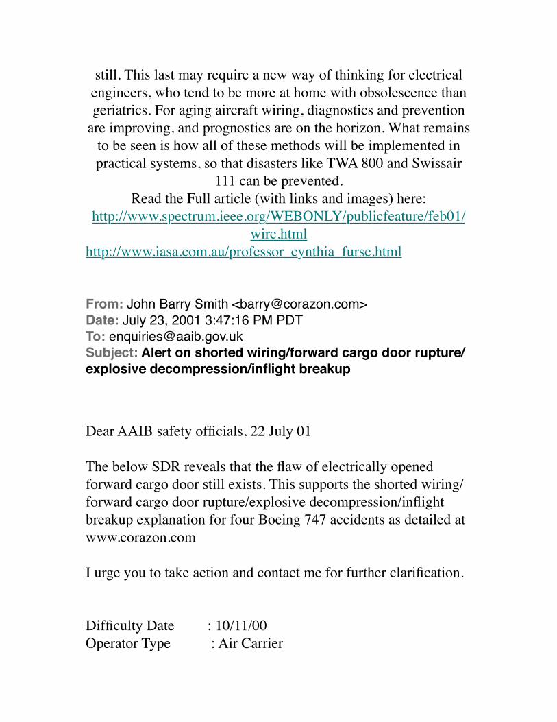
still. This last may require a new way of thinking for electrical engineers, who tend to be more at home with obsolescence than geriatrics. For aging aircraft wiring, diagnostics and prevention
are improving, and prognostics are on the horizon. What remains to be seen is how all of these methods will be implemented in practical systems, so that disasters like TWA 800 and Swissair
111 can be prevented.Read the Full article (with links and images) here:
http://www.spectrum.ieee.org/WEBONLY/publicfeature/feb01/wire.html
http://www.iasa.com.au/professor_cynthia_furse.html
From: John Barry Smith <[email protected]>Date: July 23, 2001 3:47:16 PM PDTTo: [email protected]: Alert on shorted wiring/forward cargo door rupture/explosive decompression/inflight breakup
Dear AAIB safety officials, 22 July 01
The below SDR reveals that the flaw of electrically opened forward cargo door still exists. This supports the shorted wiring/forward cargo door rupture/explosive decompression/inflight breakup explanation for four Boeing 747 accidents as detailed at www.corazon.com
I urge you to take action and contact me for further clarification.
Difficulty Date : 10/11/00Operator Type : Air Carrier
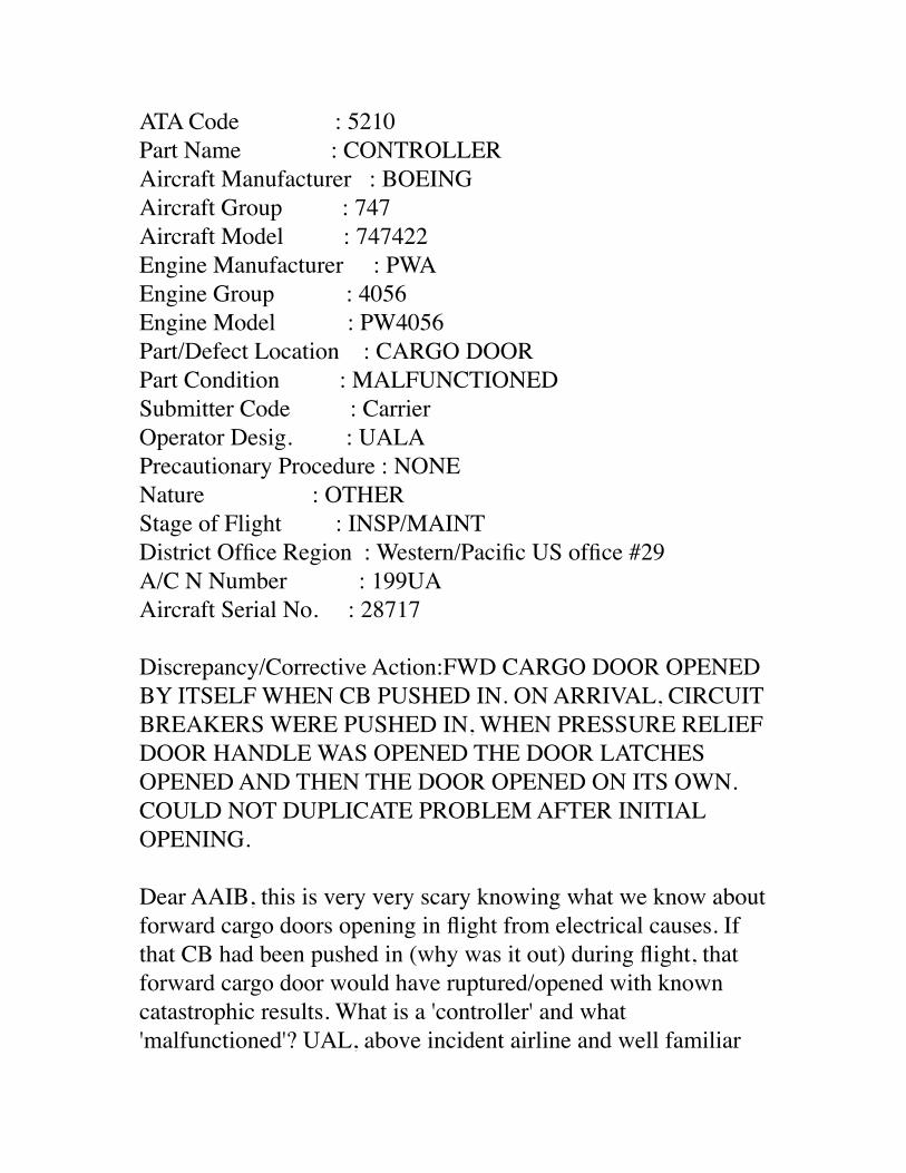
ATA Code : 5210Part Name : CONTROLLERAircraft Manufacturer : BOEINGAircraft Group : 747Aircraft Model : 747422Engine Manufacturer : PWAEngine Group : 4056Engine Model : PW4056Part/Defect Location : CARGO DOORPart Condition : MALFUNCTIONEDSubmitter Code : CarrierOperator Desig. : UALAPrecautionary Procedure : NONENature : OTHERStage of Flight : INSP/MAINTDistrict Office Region : Western/Pacific US office #29A/C N Number : 199UAAircraft Serial No. : 28717
Discrepancy/Corrective Action:FWD CARGO DOOR OPENED BY ITSELF WHEN CB PUSHED IN. ON ARRIVAL, CIRCUIT BREAKERS WERE PUSHED IN, WHEN PRESSURE RELIEF DOOR HANDLE WAS OPENED THE DOOR LATCHES OPENED AND THEN THE DOOR OPENED ON ITS OWN. COULD NOT DUPLICATE PROBLEM AFTER INITIAL OPENING.
Dear AAIB, this is very very scary knowing what we know about forward cargo doors opening in flight from electrical causes. If that CB had been pushed in (why was it out) during flight, that forward cargo door would have ruptured/opened with known catastrophic results. What is a 'controller' and what 'malfunctioned'? UAL, above incident airline and well familiar
with UAL 811, had habit of pulling door CB out and were told to stop, order 8300.10 below. They are apparently still pulling the door CB and it may have saved their ass/es.
"Door opened on its own" should have sent chills down your back, it did mine.
Sincerely,
John Barry Smith(831) 659-3552 phone551 Country Club Drive,Carmel Valley, CA [email protected] pilot, instrument rated, former FAA Part 135 certificate holder.US Navy reconnaissance bombardier navigator, RA-5C 650 hours.US Navy patrol crewman, P2V-5FS 2000 hours.Air Intelligence Officer, US NavyRetired US Army Major MSCOwner Mooney M-20C, 1000 hours.Survivor of sudden night fiery fatal jet plane crash in RA-5C
ORDER: 8300.10
APPENDIX: 4
BULLETIN TYPE: Flight Standards Information Bulletin (FSIB)ÊÊÊÊ for Airworthiness (FSAW)
BULLETIN NUMBER: FSAW 93-50
BULLETIN TITLE: Inappropriate Use of Circuit Breakers During B-747 Lower Lobe Cargo Door Operation
EFFECTIVE DATE: 06-02-94ÊÊÊÊ---------------------------------------------------------------1. SUBJECT. This FSIB informs inspectors of unsafe proceduresbeing used by some operators to close and lock the lower lobecargo doors of the Boeing 747 (B-747) series aircraft.
2. BACKGROUND.Ê
A. This bulletin was developed after an inquiry by a foreignairworthiness authority into the special procedures used by aspecific operator to close and lock the lower lobe cargo doors ofB-747 series aircraft. The special procedure included in theoperator's maintenance manual called for manual tripping of thecargo door control circuit breakers and the section 2 groundhandling bus circuit breaker in order to further remove thepossibility of power being applied accidentally to the cargo doorcontrol circuitry.
B. The manual tripping of the circuit breakers in special cargodoor lock procedures is unnecessary and decreases the reliabilityof the circuit breakers to perform their intended function.Frequent switching of the breakers could cause them to tripbefore the point of rated voltage or not to trip at all. Bothcases could have adverse effects (such as the following) inrelation to the safe operation of the cargo doors:Ê
(1) Circuit breakers that trip before the point of rated voltage
would cause increased manual operation of the cargo doors.Ê
(2) Manual operation could introduce additional failureconditions, such as out-of-sequence operation and overdriving ofthe cargo door mechanisms.Ê
(3) Service history has shown that manual operation of the cargodoors is more prone to cause damage; for example, the failure ofa breaker to trip at the point of rated voltage could lead tofailed components and fire.
2
C. The revision to the B-747 cargo door lock sectors warningsystem, in airplanes compliant with Airworthiness Directive (AD)90-09-06, provides an increased level of integrity so that manualtripping of the circuit breakers is not necessary to prevent thepossibility of an uncommanded opening of the cargo doors.Furthermore, power to the cargo door is automatically removed bythe Master Latch Lock System upon first motion of the MasterLatch Lock Switch away from the fully unlocked position.
3. ACTION. Principal maintenance inspectors (PMI) havingcertificate management responsibilities for operators of Boeing747 series aircraft should ensure that this information isbrought to the attention of their respective operators. Anyoperators using this procedure should be discouraged from itscontinued use.
4. INQUIRIES. This FSIB was developed by SEA.AEG. Anyquestions regarding this information should be directed to
AFS-510 at (703) 661-0333, extension 5018.
5. EXPIRATION. This FSIB will expire on 05-31-95.
/s/Edgar C. Fell
Below from NTSB AAR 92/02 for United Airlines Flight 811 1.17.6 Uncommanded Cargo Door Opening--UAL B-747, JFK AirportOn June 13, 1991, UAL maintenance personnel were unable to electrically open the aft cargo door on a Boeing 747-222B, N152UA, at JFK Airport, Jamaica, New York. The airplane was one of two used exclusively on nonstop flights between Narita, Japan, and JFK. This particular airplane had accumulated 19,053 hours and 1,547 cycles at the time of the occurrence.The airplane was being prepared for flight at the UAL maintenance hangar when an inspection of the circuit breaker panel revealed that the C-288 (aft cargo door) circuit breaker had popped. The circuit breaker, located in the electrical equipment bay just forward of the forward cargo compartment, was reset, and it popped again a few seconds later. A decision was made to defer furtherwork until the airplane was repositioned at the gate for the flight. The airplane was then taxied to the gate, and work on the door resumed.The aft cargo door was cranked open manually, the C-288 circuit breaker was reset, and it stayed in place. The door was then closed electrically and cycled a couple of times without incident. With the door closed, one of the two "cannon plug" (multiple pin) connectors was removed from the J-4 junction box located
on the upper portion of the interior of the door. The wiring bundle from the junction box to the fuselage was then manipulated while readings were taken on the cannon plug pins using a volt/ohmmeter. Fluctuations in electrical resistance were noted. When the plug was reattached to the J-4 junction box, the door began to open with no activation of the electrical door open switches. The C-288 circuit breaker was pulled, and the door operation ceased. When the circuit breaker was reset, the door continued to the full open position, and the lift actuator motor continued to run for several seconds until the circuit breaker was again pulled. At this time, a flexible conduit, which covered a portion of the wiring bundle, was slid along the bundle toward the J-4 junction box, revealing several wires with insulation breaches and damage.UAL personnel notified the Safety Board of the occurrence, and the airplane was examined at JFK by representatives of the Safety Board, United Airlines, and Boeing. After the wires in the damaged area were electrically isolated, electrical operation of the door was normal when the door was unlocked. When the door was locked (master latch lock handle closed), activation of the door control switches had no effect on the door. This indicated that the S2 master latch lock switch was operating as expected (removing power from the door when it was locked). After the on-site examinations, the wiring bundle was cut from the airplane and taken to the Safety Board's materials laboratory for further examination.
From: John Barry Smith <[email protected]>Date: May 28, 2002 8:28:55 PM PDTTo: [email protected]: Pan Am Flight 103
Dear Sir, 28 May 2002
I have completed my Smith aircraft accident report for Pan Am Flight 103. It reveals there was no bomb but the cause to be the shorted wiring/forward cargo door rupture/explosive decompression/inflight breakup explanation.
It is available upon request in pdf format.
Cheers,Barry SmithJohn Barry Smith(831) 659 [email protected]
From: John Barry Smith <[email protected]>Date: May 28, 2002 8:29:12 PM PDTTo: :[email protected]: Pan Am Flight 103 AAR
Dear Sir, 28 May 2002
I have completed my Smith aircraft accident report for Pan Am Flight 103. It reveals there was no bomb but the cause to be the shorted wiring/forward cargo door rupture/explosive decompression/inflight breakup explanation.
It is available upon request in pdf format.
Cheers,Barry SmithJohn Barry Smith(831) 659 3552
From: John Barry Smith <[email protected]>Date: May 28, 2002 8:29:25 PM PDTTo: [email protected]: Pan Am Flight 103 Explanation
Dear Sir, 28 May 2002
I have completed my Smith aircraft accident report for Pan Am Flight 103. It reveals there was no bomb but the cause to be the shorted wiring/forward cargo door rupture/explosive decompression/inflight breakup explanation.
It is available upon request in pdf format.
Cheers,Barry SmithJohn Barry Smith(831) 659 [email protected]
From: John Barry Smith <[email protected]>Date: August 27, 2002 9:54:54 AM PDTSubject: copy of smart email
X-From_: [email protected] Thu Apr 18 09:41:49 2002Date: Thu, 18 Apr 2002 17:41:27 +0100To: John Barry Smith <[email protected]>From: Ken Smart <[email protected]>
Subject: Mr. Bill Tucker/wiring/cargo door for PA 103 message!Cc: "Tucker, Bill" <[email protected]>
Dear Mr Smith
Thank you for your hypothesis on the immediate cause of the PanAm 103.
During the first five days of the investigation into PanAm 103 the AAIB were pursuing two general lines of inquiry. The first was that the aircraft had suffered a structural failure in-flight as a result of a defect or induced structural overload, the second was that an improvised explosive devise was responsible.
When the evidence of an improvised explosive device was found, the investigation nevertheless concentrated on discovering whether there was any evidence that a structural weakness had been exploited. In that respect the fwd. cargo door was the subject of very detailed examination. All the specialists involved were satisfied that the fwd. cargo door was correctly latched when the device detonated and that the subsequent structural failures where secondary events.
All structures by nature of their design have paths of least resistance when subjected to abnormal loading. The structure in the vacinity of large strengthened apertures such as the fwd. cargo door provide very good examples of this. The window belt on pressurised aircraft provides another and similar example. You should not be surprised to find similar patterns of breakup in structural failures that emanate from very different causes. The important differences lie in the detailed examination rather than the macro features.
I'm sorry to be the one to pour cold water on your hypothesis, but the scenario that you suggest was the subject of very considerable examination in the early stages of the Lockerbie investigation.
Ken SmartChief Inspector of Air Accidents
From: [email protected]: July 15, 2004 6:12:11 AM PDTTo: [email protected]: NTSB e-mail address
Hi Barry
Do you please have an e-mail address for the Nat Trans Safety Board?
Thanks
John WorzencraftPredisentDATARIGHT INTERNATIONAL
From: John Barry Smith <[email protected]>Date: July 15, 2004 9:11:25 AM PDTTo: [email protected]: Re: NTSB e-mail address
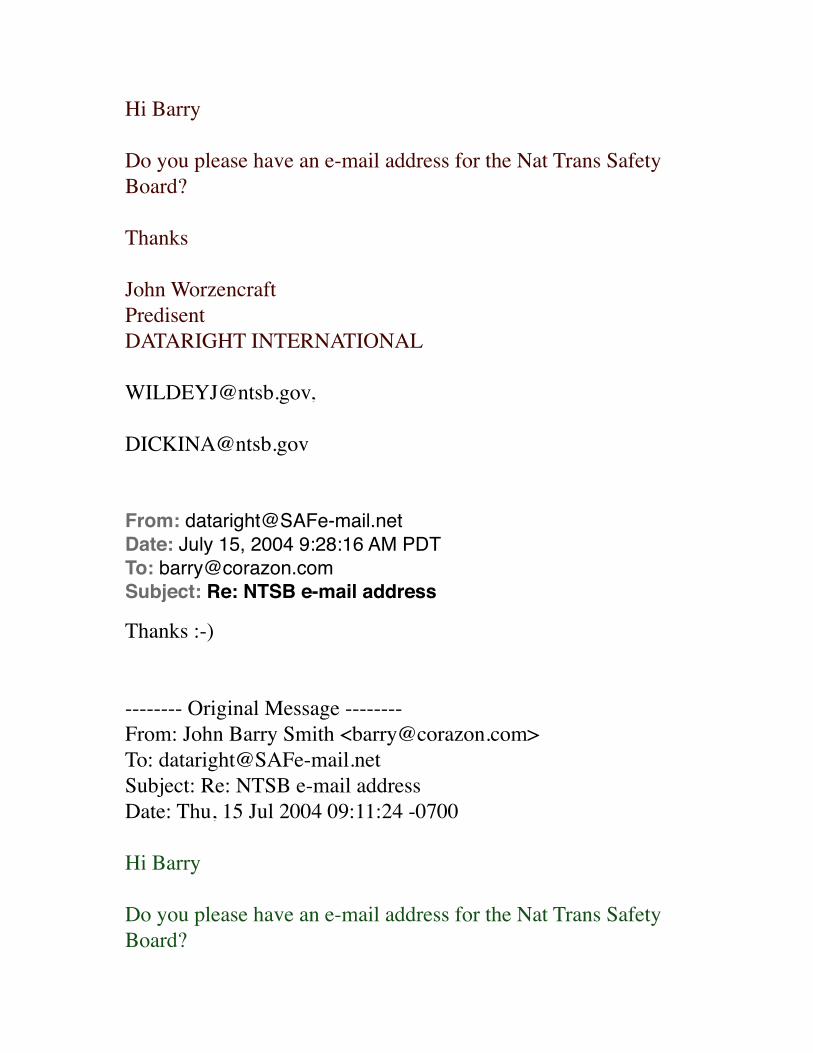
Hi Barry
Do you please have an e-mail address for the Nat Trans Safety Board?
Thanks
John WorzencraftPredisentDATARIGHT INTERNATIONAL
From: [email protected]: July 15, 2004 9:28:16 AM PDTTo: [email protected]: Re: NTSB e-mail address
Thanks :-)
-------- Original Message --------From: John Barry Smith <[email protected]>To: [email protected]: Re: NTSB e-mail addressDate: Thu, 15 Jul 2004 09:11:24 -0700
Hi Barry
Do you please have an e-mail address for the Nat Trans Safety Board?
Thanks
John WorzencraftPredisentDATARIGHT INTERNATIONAL
From: "L-Soft list server at LISTSERV.NTSB.GOV (1.8e)" <[email protected]>Date: December 16, 2005 7:27:52 AM PSTTo: [email protected]: Command confirmation request (8420AB16)
Your subscription request:
SUBSCRIBE AVIATION (no name available)
has been received. You must now reply to this message (as explainedbelow) to complete your subscription. The purpose of this confirmationprocedure is to make sure that you have indeed requested to be added tothe list.
To respond, use the Reply function in your email; type OK in
the body ofthe message.
Your request will be cancelled automatically if LISTSERV does not receiveyour confirmation within 48 hours.
From: "L-Soft list server at LISTSERV.NTSB.GOV (1.8e)" <[email protected]>Date: December 16, 2005 7:38:27 AM PSTTo: [email protected]: Re: Command confirmation request (8420AB16)
OKConfirming:SUBSCRIBE AVIATION (no name available)You have been added to the AVIATION list.
From: "L-Soft list server at LISTSERV.NTSB.GOV (1.8e)" <[email protected]>Date: December 16, 2005 7:38:27 AM PSTTo: [email protected]: You are now subscribed to the AVIATION listReply-To: [email protected]
Fri, 16 Dec 2005 10:38:27
Your subscription to the AVIATION list (NTSB AVIATION LIST) has beenaccepted.
Please save this message for future reference, especially if this is thefirst time you are subscribing to an electronic mailing list. If you everneed to leave the list, you will find the necessary instructions below.
To remove your name from the list at any time send the "SIGNOFF AVIATION"command via email to [email protected].
From: John Barry Smith <[email protected]>Date: September 6, 2009 12:03:22 AM PDTTo: [email protected]: This explains a lot
James F. (Jim) Wildey IISenior MetallurgistSequence Group Chairman, TWA flight 800 investigation.National Resource Specialist - Metallurgy
Experience:Employed at the Safety Board in the Materials Laboratory for nearly 25 years, since September, 1975. Chief of the laboratory for 2+ years. Participated in many of the major accidents involving component or structural failures investigated by the Board and foreign countries including 1985 Indian Airlines Boeing 747 bombing, Atlantic Ocean 1988 Aloha Airlines 737 structural failure, Hawaii 1988 Pan Am 103 bombing, Lockerbie, Scotland 1989 United Airlines 747 cargo door failure, Honolulu, Hawaii 1989 United Airlines DC-10 fan disk failure, Sioux City,
Iowa 199? DC-10 bombing, Chad, Africa 1996 TWA 800 NTSB Chairman's award, (1989), Recipient of Aviation Week and Space Technology Laurel Award, February 1998, in recognition of the analysis of the breakup of the TWA 800 airplane. Presents a course entitled Fracture Recognition, to students at the NTSB Aircraft Accident Investigation School.
Dear Aviation Public Safety Officials, the one person who has a vested interest in TWA 800 not being a wiring/cargo door event is Mr. Wildey. He is officially connected with AI 182 and PA 103, two events which are officially not wiring/cargo door events but would be if TWA 800 were to become a wiring/cargo door event. This would explain why he is so adamant that TWA 800 was not a cargo door rupture in flight, contrary to photographic and CVR evidence, but a spontaneous center tank explosion which lacks the crucial factor of an identified ignition source: He is protecting his opinions of years past, opinions in hindsight which are now suspect, based on matching evidence in the electrical/cargo door UAL 811 accident.
Mr. Wildey's opinions about the destruction sequence and whether the cargo door ruptured in flight are invalid as they are given by an official with a conflict of interest as well as the fact he is not an aircraft accident investigator.
Therefore the entire question of the initial event of TWA 800 and whether the cargo door opened in flight should be renewed by a NTSB aircraft accident investigator who is not connected to AI 182 or PA 103.
Below is a photograph of UAL 811 giving as evidence a similar shape of destruction on the starboard side of TWA 800. The port side of TWA 800 is as smooth as the port side of UAL 811. Both
doors had ruptures at the midspan latches. They match in destruction evidence and probable cause, electrical/wiring/cargo door event.
Sincerely,
John Barry Smith(831) 659-3552 phone551 Country Club Drive,Carmel Valley, CA [email protected] pilot, instrument rated, former FAA Part 135 certificate holder.US Navy reconnaissance navigator, RA-5C 650 hours.US Navy patrol crewman, P2V-5FS 2000 hours.Air Intelligence Officer, US NavyRetired US Army Major MSCOwner Mooney M-20C, 1000 hours.Survivor of sudden night fiery fatal jet plane crash in RA-5C
Aging, brittle wiring within aircraft poses a hidden hazard that emerging technologies aim to address
Down to the WireBy Cynthia Furse & Randy Haupt, Utah State University
As today's military and commercial aircraft age past their teen years, the many kilometers of wiring buried deep within their structures begin to crack and fray. Once thought to be rare and
benign, such faults are found by the hundreds in a typical aircraft. Unlike obvious cracks in a wing or an engine, though, damaged wire is extremely difficult to detect. But the resulting
arcing and electromagnetic emissions can be just as deadly:
faulty wiring has been blamed for the downing of Swissair 111 near Nova Scotia in 1998 and of TWA 800 off New York's Long Island in 1996 [see http://www.spectrum.ieee.org/WEBONLY/publicfeature/feb01/wiref1.html ]. Indeed, any densely wired system is vulnerable--the space shuttle, nuclear power plants,
subways and railroads, even the family car.Public scrutiny has prompted strongly worded recommendations
from the likes of NASA, the U.S. Federal Aviation Administration, and the National Transportation Safety Board (NTSB) [see "Government and Industry Take Action" at http://
www.spectrum.ieee.org/WEBONLY/publicfeature/feb01/wiresb1.html ]. "The safety of the nation's wire systems is an
issue of major importance to us all," noted a White House report issued last fall. Several months earlier, the NTSB concluded its lengthy investigation of TWA 800 with the verdict that a short circuit sparked an explosion in the center wing fuel tank. The
condition of the wiring, it noted, was "not atypical for an airplane of its age." Among the NTSB's recommendations was to
incorporate into aircraft "new technology, such as arc-fault circuit breakers and automated wire test equipment."
Solutions are not straightforward. Among the most promising technologies are advanced reflectometry methods, for routine
maintenance; so-called smart wire systems, for continual, on-the-spot wire testing; and arc-fault circuit breakers and advanced fire
suppression techniques, for minimizing damage and injury should a fault occur. Remaining challenges include detecting the minuscule insulation breaks that encourage arcing; optimizing the benefits and mitigating the risks of the various wire testing
techniques; and getting a better handle on the labyrinthine complexity of aircraft wiring systems.
Failing the test of timeA healthy wire is perhaps the simplest, yet most important,
element in an electrical system. Typically, a copper conductor
(from 1 to 10 mm in diameter) is covered by a thin outer insulation (from 0.5 to 2 mm thick). Damaged insulation can
expose the copper, giving rise to arcs, shorts, and electromagnetic emission and interference. Arcing occurs when
current flows from the wire through ionized air to another conducting object, such as a second wire or the aircraft structure. A short circuit channels the current to an undesired conductor. If
an external shield or braid protecting a wire is broken, the resulting antenna radiates the signal on the wire.
As the wire ages, the insulation may become brittle and crack. Vibration can also chafe the insulation as wires vibrate against each other, a tie-down, or any other hard surface. Maintenance can also be hard on wires, as they may be nicked by workers' pliers, or bent beyond their tolerable radius, or sprinkled with
metal drill shavings, chemicals or water, or even used as stepladders in hard-to-reach places. [see Photos at http://www.spectrum.ieee.org/WEBONLY/publicfeature/feb01/
wiref1.html ] that show cracked and singed wiring taken from U.S. Navy planes.]
But perhaps the greatest concern is the breakdown of the wire's insulation when exposed to moisture. Insulation made from
polyimide film, often referred to by the brand-name Kapton, was once thought to be the ideal wiring insulation and was widely used in both military and commercial aircraft during the 1970s
and early '80s. A long-chain polymer that is both tough and durable, with a very high resistivity, Kapton provides excellent
electrical insulation even at a thickness of less than a millimeter.What was not known initially was how Kapton held up to the
moisture that tends to condense in or near aircraft wiring harnesses. This moisture is so prevalent that most wires are
outfitted with a drip loop, which prevents water droplets from running down the cables and into critical electronics. Exposed to this moisture, Kapton's long polymer chains break down, and the
insulation becomes brittle, developing small cracks that in turn let in even more moisture. So-called wet arcs begin to flow along
these cracks, creating intermittent arcs too small to trip normal circuit breakers and often too small even to interfere with the
signal transfer along the wire. Nonetheless, the tiny arcs do begin to carbonize the insulation, and carbon is an excellent conductor. Once enough carbon has built up ("enough" depends on the type and thickness of the insulation, the power handling of the wire, and other factors), there can be a large explosive flashover, with
exposed wires spewing molten metal.One would hope that Kapton cracks are relatively rare. Not so,
according to a recent report by Lectromechanical Design Co., an electrical research firm based in Sterling, Va. Using a proprietary tool called the DelTest, Letromec engineers tested the wiring in a
Boeing 747, an Airbus A300, a Lockheed L-1011, and two DC-9s that were each over 20 years old and had been retired by commercial airlines within the previous six months. The results:
13 cracks per 1000 meters of wire in the L-1011, down to 1.6 cracks per 1000 meters in one of the DC-9s. With approximately
240 km of wire in the L-1011, this amounted to over 3000 cracks, each a potential cause of catastrophic arcing.
Some time after Kapton's problems came to light, in the late '70s, its use was cut back, and aircraft manufacturers began replacing
it in some of the most critical wiring systems in planes in service. Alternatives to Kapton include polyvinylchloride, glass, nylon,
polyester, and teflon. But polyimide can still be found on thousands of aircraft in service, including the McDonnell
Douglas MD-11 and older Boeing 737s and 767s.How old is too old?
Updating rather than replacing old planes has become a standard way to save money. Some aircraft being designed today, such as the Joint Strike Fighter, may fly 100 years. Similarly, the B-52s
flown by the U.S. Air Force were built in 1961‹62 and are

expected to remain operational until 2045. Its designers would have never dreamed that this plane would fly for over 80 years. Indeed, not much thought was given to replacing or inspecting the wiring, because the planes were to have been retired long
before any problems developed.So when is it time to scrap an airplane because its wires are too old? The answer depends on a complex array of factors--among them calendar age, manufacturing variations, exposure to water, ultraviolet light, temperature, vibration and g-forces, and stress
during normal use and maintenance.Planes over 20 years old are virtually guaranteed to have wiring problems, many of which turn up during routine maintenance.
The average age of civilian aircraft in use today is 18 years, and the average age of military planes is 16 years. [See table at http://
www.spectrum.ieee.org/WEBONLY/publicfeature/feb01/wiret1.html ] Of course, most fleets are composed of a mix of
aircraft types and ages. Trying to relate this information to wiring failure probability rates, such as those in the table at http://www.spectrum.ieee.org/WEBONLY/publicfeature/feb01/
wiret2.html , gives some idea why wiring problems are endemic today.
Short of replacing an entire aircraft, how about replacing just the wiring system? That also turns out to be hugely expensive--
anywhere from US $1 million to $5 million for a typical aircraft. Determining what, when, or whether to replace then means
weighing cost against risk--a decision complicated by the fact that neither the cost nor the risk has yet been fully characterized.
What is more, military planes get exposed to more hostile environments than the average commercial plane, so
extrapolation to other types of planes is not necessarily accurate.The maintenance nightmare
Snaking through an aircraft are many kilometers of wire--some 17.5 km in a Navy F-18C/D fighter, 240 km in a typical wide-
body jet. The wire is literally built into the aircraft, running through fuel tanks, and twisted around hydraulic lines. Just
reaching the wiring harness often entails dismantling an aircraft's external structure. And merely touching a wire, let alone
disconnecting, handling, and reconnecting it, heightens the risk that the wire will be damaged.
But maintenance workers do not always show due respect. They have been known to stand on wires instead of step stools, to cut and splice them poorly to get them out of the way of difficult-to-reach places, and to smack connectors with hammers to loosen
them. Tiny razor-sharp metal shavings from maintenance or upgrades, coupled with ordinary aircraft vibration, create the
perfect conditions for insulation damage.Other parts of the aircraft never get touched, but are no less
problematic. The dust bunnies and chaff that collect in these out-of-sight areas are excellent tinder to turn sparks into smoke and
flames. Then there's the sticky "syrup" that collects in and around wire bundles. This well-aged potion of condensation, toilet and
galley leaks, dust, hydraulic fluid, and various unnamable ingredients is intensely caustic to most kinds of insulation. One of the Navy and FAA directives for making aging wiring safer
has been simply to improve cleanliness within aircraft!Compounding the maintenance nightmare is its high cost. By one estimate, the Navy spends 1.8 million person-hours each year to
troubleshoot and repair its aircraft wiring systems.Why state of the art isn't enough
Wire troubleshooting is still very much a hands-on art that has changed little over the last 40 years. Among the techniques in
current use are visual inspection, several versions of reflectometry, and impedance testing. Each technique has its
advantages and, more importantly, disadvantages.Visual inspection is still the most common way to check for
wiring failures. It entails accessing the cables and then carefully
checking the insulation for holes and cracks, often no larger than the head of a pin. Whole sections of wiring never get inspected: chafed insulation can be hidden under clamps or around corners, or within multiwire bundles, each consisting of 75 or more wires.
And many wire bundles are built right into the walls of the aircraft.
Another approach involves measuring the cable's resistance from end to end. A low resistance means the cable is "good," and a
high resistance means that it is broken. When a very high voltage (500 V or more) is placed between adjacent, supposedly
unconnected wires, current leakage from one wire to another can indicate degraded insulation.
There is some concern, though, that high voltage may in itself damage the insulation. So nondestructive resistance tests, such as those developed by Eclypse International Corp., Corona, Calif., use voltages of 28 V or less. A floating comparator analyzes the
currents on the cable as the input current is stepped through several levels. In a healthy cable, Ohm's Law predicts that the
resistance will stay the same for all current levels. If it does not, then something is wrong with the cable. The method has been
used to locate cold solder joints, bad crimps, carbonization of the cable or connectors, and foreign matter on or near the cables. And unlike the high-voltage tests, it can be used on a fueled
airplane. It does, though, still require disconnecting and reconnecting the cables.
Several techniques now used or under development involve reflectometry. Common to all these methods is the sending of a
signal (a pulse, sine wave, or the like) down the wire and sensing the reflection that returns from the wire's end. They are most
useful for detecting so-called hard errors, such as short circuits, but have not proven useful for less obvious wire problems.
Time domain reflectometry (TDR) is customarily used when a wiring problem is already suspected. A short, typically
rectangular pulse is sent down the cable, and the cable impedance, termination, and length give a unique temporal signature to the reflected signal. A trained technician then
interprets the signature to determine the health of the cable. Such signal interpretation is particularly necessary for aircraft systems,
where wires branch into complicated network structures and connect to active avionics. The running joke about TDR is that it
requires a Ph.D. to use.Standing-wave reflectometry (SWR) involves sending a
sinusoidal waveform down the wire. A reflected sinusoid is returned from the wire's end, and the two signals add to a
standing wave on the line. The peaks and nulls of this standing wave give information on the length and terminating load of the cable; a healthy line's wave pattern will be distinct from that of a line with an open or short circuit. The edge this method has over
TDR is that the electronics are simpler and therefore less expensive.
Like SWR, frequency domain reflectometry (FDR) uses sine waves. FDR, though, directly measures the phase difference
between the incident and reflected waves; any faults in the line will generate resonances between the two signals. This method is
being developed for in situ wire testing by researchers at Utah State University with support from Management Sciences Inc., Albuquerque, N.M., and the Naval Air Systems Command. The
goal is to allow preflight testing of cables with the touch of a button, and without the risk of damaging the cables by
disconnecting them.On the horizon
Because of the shortcomings in the above techniques, researchers are now looking at several new technologies. These include
automated reflectometry testing; smart wire systems for real-time, on-the-spot testing; and, in the event of an in-flight failure, advanced fire suppression methods and arc-fault circuit breakers.
Automating the reflectometry methods now in use may one day mean that maintenance workers will be able to gauge a cable's
health with minimal physical intervention. A hand-held unit would clamp around the wire, rather than directly connecting to
it. Recently, a fully automated TDR unit was developed by Phoenix Aviation and Technology. It provides a wider range of
fault diagnostics and prognostics, with precise location and interpretation of the fault. The same software can be easily
embedded into application-specific IC format or similar small computing platforms, thus paving the way for real-time
embedded conductor monitoring.All the same, reflectometry is pushing the state of the art when it
comes to finding small insulation cracks, detecting chafed insulation before arcs occur, and locating an arc's source. Better detection of these tiny anomalies may be achievable by wetting the cable with water or saline solution, or filling the plane with
inert gas.Perhaps the maintenance worker's greatest nightmare is finding
faults that come and go. These so-called ticking faults arise from vibration, temperature change, moisture, g-forces,
electromagnetic interference, and so on. Diagnosing the problem requires systems that can function in flight, where ticking faults
usually occur.Smart wire systems are thus being designed for testing cables continuously, both before takeoff and during a flight. Systems
now under development include a frequency domain reflectometer, on-board processor, environmental sensors, and
wireless communication system integrated into a single miniaturized unit, hundreds of which can be embedded in the wiring system. They will monitor the health of the cable and
guide cable maintenance, and even detect any faults that occur and correct them in real time.
For the aircraft being designed today, a novel kind of wiring with
a complete array of embedded sensors is being proposed. This is particularly critical for long-lived planes such as the Joint Strike
Fighter. Weight and space constraints are likely to drive this technology to nanoscale sensors, emerging material science technologies, and microelectromechanical system devices.
Of course, wire failures will still occur. New technologies that can help limit the damage in such an event include arc-fault
circuit breakers and fire suppression methods.------------------------------------------------------------------------------
--Smart wire systems will continuously monitor the cable's
health and correct faults as they occur------------------------------------------------------------------------------
--Ordinary circuit breakers are heat-sensitive bimetal elements that
trip only when a large current passes through the circuit long enough to heat the element. This power may be on the order of
1000 percent of the rated current for 0.35 to 0.8 seconds. By comparison, a single arc fault may last only 1.25 ms, and a series
of events may last 20‹30 ms. Too fleeting to trip the circuit breaker, these arc faults can nonetheless cause catastrophic local damage to the wire. Fires have been known to break out with the
breaker still intact.Arc-fault circuit breakers contain sophisticated electronics to
sample the current on the wire at submillisecond intervals. Both time and frequency domain filtering are used to extract the arc-
fault signature from the current waveform. This signature may be integrated over time to discriminate, by means of pattern-
matching algorithms, between a normal current and a sputtering arc-fault current. And so ordinary transients, due to, say, a motor being turned on and off, can be distinguished from the random
current surges that occur with arcing.Arc-fault breakers are already required in new home wiring in
the United States and are now being miniaturized for use on aircraft. Normally these breakers either are used in tandem with a traditional heat-sensitive breaker or else include a heat-sensitive element in addition to the pattern-matching electronics. Ideally, circuitry will also be added to locate the fault after the breaker
has tripped.Once a fire starts on an aircraft, it spreads rapidly, aided by
Mylar-backed insulation in the cabin walls, limited access to fire extinguishers, and so on. New extinguisher designs that rely on super-fine, high-pressure mists of water, inert gases, and other
techniques are now being developed to put out all types of aircraft fires, including those due to faulty wiring.
Amazingly little is known about how and why wires age, but polymer scientists are making up for lost time. Among other
things, they are studying the chemical and physical changes and resultant effects on electrical insulation properties that occur as wires age. One goal is to find new materials to replace copper
wiring in signal-transfer and electromagnetic interference shielding on aircraft, as well as new types of wire insulation that
resist chafing and have extended life and built-in diagnostics.Not to panic
If you happen to read this article while flying, do not panic. Few wiring problems end in disaster. There is cause for concern,
though, as the air fleet continues to age, and our reliance on air transport grows. While an aircraft's other major systems undergo
preflight testing and regular inspection and maintenance, its central nervous system--wiring--has been long neglected. Sorely needed are new maintenance methods that account for the aging of wires, as is done for aging structural and computer systems.Diagnosis is good. Prognosis is better. And prevention is better still. This last may require a new way of thinking for electrical
engineers, who tend to be more at home with obsolescence than geriatrics. For aging aircraft wiring, diagnostics and prevention
are improving, and prognostics are on the horizon. What remains to be seen is how all of these methods will be implemented in practical systems, so that disasters like TWA 800 and Swissair
111 can be prevented.Read the Full article (with links and images) here:
http://www.spectrum.ieee.org/WEBONLY/publicfeature/feb01/wire.html
http://www.iasa.com.au/professor_cynthia_furse.html
From: John Barry Smith <[email protected]>Date: September 6, 2009 12:03:22 AM PDTTo: [email protected]: Mr. Husseini, EgyptAir mechanical, not human error
Dear Mr. Husseini,
News report:Data released to date by the safety board supports no scenario for the Boeing 767's flight path other than one in which ``the occupant of the right seat disconnected the autopilot and aggressively pushed forward on the yoke, holding that big jet in an incredible screaming dive,'' Nance said.
Not true above, Mr. Husseini, autopilots on a 767 have disconnected by themselves in the past without human intervention. (MartinAir 767) and down inputs to the elevators have happened before on a Boeing airliner without human input. (Boeing 747)
The evidence of history shows that the events that led to EgyptAir 990 could have been a repeat of mechanical faulty events in Boeing airliners, specifically, uncommanded autopilot
disconnect and uncommanded down right elevator.
To blame the crew is an injustice and allows the mechanical fault to persist where it may occur again. Something must be done, sir.
Cheers,Barry Smith
John Barry Smith(831) 659-3552 phone551 Country Club Drive,Carmel Valley, CA [email protected] 99
At 9:30 AM -0800 11/22/99, John Barry Smith wrote:The flight from London Heathrow to Bangkok took off two minutes behind another 'Heavy' Boeing 747-400. As the aircraft climbed through about 100 feet agl with the landing gear retraction in progress, the aircraft suddenly pitched down from 14¡ nose up to 8¡ nose up due to uncommanded full down travel of the right elevators.
At 9:30 AM -0800 11/22/99, John Barry Smith wrote:The Boeing 767-300ER had multiple electronic (elec) anomolies, en route, including illuminated warning lights, erroneous display indications, uncommanded autopilot disconnects, & failure of flight (flt) instruments.
------------------------------------------------------------------------
------------------------------------------------------------------------
12:06 PM ET 11/24/99
EgyptAir Data Points to Human Cause
EgyptAir Data Points to Human Cause By GLEN JOHNSON= Associated Press Writer= WASHINGTON (AP) _ Despite a diplomatic dispute over what was said on the EgyptAir Flight 990 cockpit voice tape, investigators can still point to hard evidence from the plane's other ``black box'' that a human hand caused the Oct. 31 crash. It is that evidence, documented by the plane's flight data recorder, that allowed National Transportation Safety Board Chairman James Hall to make the unusually early pronouncement that the plane did not appear to have been brought down by a mechanical problem or bad weather. The recorder, among the most advanced ever handled by the safety board, also does not support any theory of a bomb, U.S. officials say. Some Egyptian authorities suspect a bomb brought down the New York-to-Cairo flight, killing all 217 aboard. That theory has been the subject of wide speculation in Egypt. Gen. Issam Ahmed, a senior Egyptian transportation ministry official, said today that the plane crashed because of an explosion. He said the cases of both black boxes, located in the tail, were severely damaged, which ``confirms that the tail of the plane ... was subjected to an explosion at the height of 33,000 feet''
because of ``an internal or external explosion.'' Ahmed said he believed a missile or bomb caused it. U.S. investigators believe the crash may have been caused by Gameel El-Batouty, a backup pilot who apparently was alone in the cockpit shortly before the crash. The cockpit recorder picked up the sound of the right-seat occupant uttering a statement before the plane began its dive toward the Atlantic Ocean. What was said, its translation from Arabic to English and its meaning in the Egyptian culture have triggered diplomatic tension between the two countries. ``We don't even have to discuss what was said by the occupant of the right seat in order to have a prima facie case that a human being caused this accident,'' said John Nance, an airline captain, lawyer and aviation author. Data released to date by the safety board supports no scenario for the Boeing 767's flight path other than one in which ``the occupant of the right seat disconnected the autopilot and aggressively pushed forward on the yoke, holding that big jet in an incredible screaming dive,'' Nance said. Such analysis is based on information from the Allied Signal Universal Flight Data Recorder aboard the EgyptAir plane. When TWA Flight 800 exploded in the skies off Long Island in July 1996, investigators were left with a flight data recorder that documented only 19 flight parameters. The unit aboard the EgyptAir plane logged the performance of 55 aircraft systems and over 150 pieces of flight information on a computer chip. Hall said Monday: ``The board has not found any information to believe that this is a mechanical or weather-related event that occurred. But our investigation is far from complete.'' Among the evidence gleaned from the EgyptAir data recorder: _The plane was in a level cruise both before and for eight seconds after the autopilot was switched off, indicating it was a
normal flight until the nose was pushed downward. _The plane's master warning alarm was not sounded until 14 seconds after the dive began, the same time the plane exceeded its maximum design speed of Mach 0.86. The alarm is designed to sound for five reasons, including excessive speed and a cabin depressurization that would likely follow the explosion of a bomb. While pilots are taught to dive to a lower altitude in the event of a decompression, the data recorder shows no loss of cabin pressure. _The plane's elevator panels, which sit on both sides of the tail and pitch the nose up and down, made an extremely rare in-flight split in direction. Boeing designs the 767 so the panels go in opposite directions only with a sustained push of over 50 pounds of pressure on either the captain's or the co-pilot's control stick. In the case of Flight 990, the side linked to the co-pilot's control stick remained pushed down _ pointing the nose toward the ocean _ while the side linked to the captain's stick was pulled up. Investigators believe the captain may have returned to the cockpit as the dive began and fought with the co-pilot for control of the airplane. _Twenty-eight seconds after the dive began, the plane's engine control switches were moved from ``Run'' to ``Cutoff.'' Boeing designs the switches as ``lever locks,'' meaning they can be moved only if they are pulled outward at the same time they are lifted up or down. That prevents an accidental bump from shutting off fuel flow to the engines. While some Egyptian officials have said the pilots may have shut down the engines to restart them, Nance said that would have been premature since the recorder shows the plane was still in a dive. ``The overwhelmingly logical conclusion is that the occupant of the right seat, whom we already know was pressing forward on the yoke, took this affirmative act of killing the engines,'' he said.
------------------------------------------------------------------------
------------------------------------------------------------------------
From: John Barry Smith <[email protected]>Date: September 6, 2009 12:03:22 AM PDTTo: [email protected]: This explains a lot
James F. (Jim) Wildey IISenior MetallurgistSequence Group Chairman, TWA flight 800 investigation.National Resource Specialist - Metallurgy
Experience:Employed at the Safety Board in the Materials Laboratory for nearly 25 years, since September, 1975. Chief of the laboratory for 2+ years. Participated in many of the major accidents involving component or structural failures investigated by the Board and foreign countries including 1985 Indian Airlines Boeing 747 bombing, Atlantic Ocean 1988 Aloha Airlines 737 structural failure, Hawaii 1988 Pan Am 103 bombing, Lockerbie, Scotland 1989 United Airlines 747 cargo door failure, Honolulu, Hawaii 1989 United Airlines DC-10 fan disk failure, Sioux City, Iowa 199? DC-10 bombing, Chad, Africa 1996 TWA 800 NTSB Chairman's award, (1989), Recipient of Aviation Week and Space Technology Laurel Award, February 1998, in recognition of the analysis of the breakup of the TWA 800 airplane. Presents a course entitled Fracture Recognition, to students at the NTSB Aircraft Accident Investigation School.
Dear Aviation Public Safety Officials, the one person who has a vested interest in TWA 800 not being a wiring/cargo door event is Mr. Wildey. He is officially connected with AI 182 and PA 103, two events which are officially not wiring/cargo door events but would be if TWA 800 were to become a wiring/cargo door event. This would explain why he is so adamant that TWA 800 was not a cargo door rupture in flight, contrary to photographic and CVR evidence, but a spontaneous center tank explosion which lacks the crucial factor of an identified ignition source: He is protecting his opinions of years past, opinions in hindsight which are now suspect, based on matching evidence in the electrical/cargo door UAL 811 accident.
Mr. Wildey's opinions about the destruction sequence and whether the cargo door ruptured in flight are invalid as they are given by an official with a conflict of interest as well as the fact he is not an aircraft accident investigator.
Therefore the entire question of the initial event of TWA 800 and whether the cargo door opened in flight should be renewed by a NTSB aircraft accident investigator who is not connected to AI 182 or PA 103.
Below is a photograph of UAL 811 giving as evidence a similar shape of destruction on the starboard side of TWA 800. The port side of TWA 800 is as smooth as the port side of UAL 811. Both doors had ruptures at the midspan latches. They match in destruction evidence and probable cause, electrical/wiring/cargo door event.

Sincerely,
John Barry Smith(831) 659-3552 phone551 Country Club Drive,Carmel Valley, CA [email protected] pilot, instrument rated, former FAA Part 135 certificate holder.US Navy reconnaissance navigator, RA-5C 650 hours.US Navy patrol crewman, P2V-5FS 2000 hours.Air Intelligence Officer, US NavyRetired US Army Major MSCOwner Mooney M-20C, 1000 hours.Survivor of sudden night fiery fatal jet plane crash in RA-5C
Aging, brittle wiring within aircraft poses a hidden hazard that emerging technologies aim to address
Down to the WireBy Cynthia Furse & Randy Haupt, Utah State University
As today's military and commercial aircraft age past their teen years, the many kilometers of wiring buried deep within their structures begin to crack and fray. Once thought to be rare and
benign, such faults are found by the hundreds in a typical aircraft. Unlike obvious cracks in a wing or an engine, though, damaged wire is extremely difficult to detect. But the resulting
arcing and electromagnetic emissions can be just as deadly: faulty wiring has been blamed for the downing of Swissair 111
near Nova Scotia in 1998 and of TWA 800 off New York's Long Island in 1996 [see http://www.spectrum.ieee.org/WEBONLY/publicfeature/feb01/wiref1.html ]. Indeed, any densely wired system is vulnerable--the space shuttle, nuclear power plants,
subways and railroads, even the family car.
Public scrutiny has prompted strongly worded recommendations from the likes of NASA, the U.S. Federal Aviation
Administration, and the National Transportation Safety Board (NTSB) [see "Government and Industry Take Action" at http://
www.spectrum.ieee.org/WEBONLY/publicfeature/feb01/wiresb1.html ]. "The safety of the nation's wire systems is an
issue of major importance to us all," noted a White House report issued last fall. Several months earlier, the NTSB concluded its lengthy investigation of TWA 800 with the verdict that a short circuit sparked an explosion in the center wing fuel tank. The
condition of the wiring, it noted, was "not atypical for an airplane of its age." Among the NTSB's recommendations was to
incorporate into aircraft "new technology, such as arc-fault circuit breakers and automated wire test equipment."
Solutions are not straightforward. Among the most promising technologies are advanced reflectometry methods, for routine
maintenance; so-called smart wire systems, for continual, on-the-spot wire testing; and arc-fault circuit breakers and advanced fire
suppression techniques, for minimizing damage and injury should a fault occur. Remaining challenges include detecting the minuscule insulation breaks that encourage arcing; optimizing the benefits and mitigating the risks of the various wire testing
techniques; and getting a better handle on the labyrinthine complexity of aircraft wiring systems.
Failing the test of timeA healthy wire is perhaps the simplest, yet most important,
element in an electrical system. Typically, a copper conductor (from 1 to 10 mm in diameter) is covered by a thin outer
insulation (from 0.5 to 2 mm thick). Damaged insulation can expose the copper, giving rise to arcs, shorts, and
electromagnetic emission and interference. Arcing occurs when current flows from the wire through ionized air to another
conducting object, such as a second wire or the aircraft structure.
A short circuit channels the current to an undesired conductor. If an external shield or braid protecting a wire is broken, the
resulting antenna radiates the signal on the wire.As the wire ages, the insulation may become brittle and crack. Vibration can also chafe the insulation as wires vibrate against each other, a tie-down, or any other hard surface. Maintenance can also be hard on wires, as they may be nicked by workers' pliers, or bent beyond their tolerable radius, or sprinkled with
metal drill shavings, chemicals or water, or even used as stepladders in hard-to-reach places. [see Photos at http://www.spectrum.ieee.org/WEBONLY/publicfeature/feb01/
wiref1.html ] that show cracked and singed wiring taken from U.S. Navy planes.]
But perhaps the greatest concern is the breakdown of the wire's insulation when exposed to moisture. Insulation made from
polyimide film, often referred to by the brand-name Kapton, was once thought to be the ideal wiring insulation and was widely used in both military and commercial aircraft during the 1970s
and early '80s. A long-chain polymer that is both tough and durable, with a very high resistivity, Kapton provides excellent
electrical insulation even at a thickness of less than a millimeter.What was not known initially was how Kapton held up to the
moisture that tends to condense in or near aircraft wiring harnesses. This moisture is so prevalent that most wires are
outfitted with a drip loop, which prevents water droplets from running down the cables and into critical electronics. Exposed to this moisture, Kapton's long polymer chains break down, and the insulation becomes brittle, developing small cracks that in turn
let in even more moisture. So-called wet arcs begin to flow along these cracks, creating intermittent arcs too small to trip normal circuit breakers and often too small even to interfere with the
signal transfer along the wire. Nonetheless, the tiny arcs do begin to carbonize the insulation, and carbon is an excellent conductor.
Once enough carbon has built up ("enough" depends on the type and thickness of the insulation, the power handling of the wire, and other factors), there can be a large explosive flashover, with
exposed wires spewing molten metal.One would hope that Kapton cracks are relatively rare. Not so,
according to a recent report by Lectromechanical Design Co., an electrical research firm based in Sterling, Va. Using a proprietary tool called the DelTest, Letromec engineers tested the wiring in a
Boeing 747, an Airbus A300, a Lockheed L-1011, and two DC-9s that were each over 20 years old and had been retired by commercial airlines within the previous six months. The results:
13 cracks per 1000 meters of wire in the L-1011, down to 1.6 cracks per 1000 meters in one of the DC-9s. With approximately
240 km of wire in the L-1011, this amounted to over 3000 cracks, each a potential cause of catastrophic arcing.
Some time after Kapton's problems came to light, in the late '70s, its use was cut back, and aircraft manufacturers began replacing
it in some of the most critical wiring systems in planes in service. Alternatives to Kapton include polyvinylchloride, glass, nylon,
polyester, and teflon. But polyimide can still be found on thousands of aircraft in service, including the McDonnell
Douglas MD-11 and older Boeing 737s and 767s.How old is too old?
Updating rather than replacing old planes has become a standard way to save money. Some aircraft being designed today, such as the Joint Strike Fighter, may fly 100 years. Similarly, the B-52s
flown by the U.S. Air Force were built in 1961‹62 and are expected to remain operational until 2045. Its designers would have never dreamed that this plane would fly for over 80 years. Indeed, not much thought was given to replacing or inspecting the wiring, because the planes were to have been retired long
before any problems developed.So when is it time to scrap an airplane because its wires are too
old? The answer depends on a complex array of factors--among them calendar age, manufacturing variations, exposure to water, ultraviolet light, temperature, vibration and g-forces, and stress
during normal use and maintenance.Planes over 20 years old are virtually guaranteed to have wiring problems, many of which turn up during routine maintenance.
The average age of civilian aircraft in use today is 18 years, and the average age of military planes is 16 years. [See table at http://
www.spectrum.ieee.org/WEBONLY/publicfeature/feb01/wiret1.html ] Of course, most fleets are composed of a mix of
aircraft types and ages. Trying to relate this information to wiring failure probability rates, such as those in the table at http://www.spectrum.ieee.org/WEBONLY/publicfeature/feb01/
wiret2.html , gives some idea why wiring problems are endemic today.
Short of replacing an entire aircraft, how about replacing just the wiring system? That also turns out to be hugely expensive--
anywhere from US $1 million to $5 million for a typical aircraft. Determining what, when, or whether to replace then means
weighing cost against risk--a decision complicated by the fact that neither the cost nor the risk has yet been fully characterized.
What is more, military planes get exposed to more hostile environments than the average commercial plane, so
extrapolation to other types of planes is not necessarily accurate.The maintenance nightmare
Snaking through an aircraft are many kilometers of wire--some 17.5 km in a Navy F-18C/D fighter, 240 km in a typical wide-
body jet. The wire is literally built into the aircraft, running through fuel tanks, and twisted around hydraulic lines. Just
reaching the wiring harness often entails dismantling an aircraft's external structure. And merely touching a wire, let alone
disconnecting, handling, and reconnecting it, heightens the risk that the wire will be damaged.
But maintenance workers do not always show due respect. They have been known to stand on wires instead of step stools, to cut and splice them poorly to get them out of the way of difficult-to-reach places, and to smack connectors with hammers to loosen
them. Tiny razor-sharp metal shavings from maintenance or upgrades, coupled with ordinary aircraft vibration, create the
perfect conditions for insulation damage.Other parts of the aircraft never get touched, but are no less
problematic. The dust bunnies and chaff that collect in these out-of-sight areas are excellent tinder to turn sparks into smoke and
flames. Then there's the sticky "syrup" that collects in and around wire bundles. This well-aged potion of condensation, toilet and
galley leaks, dust, hydraulic fluid, and various unnamable ingredients is intensely caustic to most kinds of insulation. One of the Navy and FAA directives for making aging wiring safer
has been simply to improve cleanliness within aircraft!Compounding the maintenance nightmare is its high cost. By one estimate, the Navy spends 1.8 million person-hours each year to
troubleshoot and repair its aircraft wiring systems.Why state of the art isn't enough
Wire troubleshooting is still very much a hands-on art that has changed little over the last 40 years. Among the techniques in
current use are visual inspection, several versions of reflectometry, and impedance testing. Each technique has its
advantages and, more importantly, disadvantages.Visual inspection is still the most common way to check for
wiring failures. It entails accessing the cables and then carefully checking the insulation for holes and cracks, often no larger than the head of a pin. Whole sections of wiring never get inspected: chafed insulation can be hidden under clamps or around corners, or within multiwire bundles, each consisting of 75 or more wires.
And many wire bundles are built right into the walls of the aircraft.
Another approach involves measuring the cable's resistance from end to end. A low resistance means the cable is "good," and a
high resistance means that it is broken. When a very high voltage (500 V or more) is placed between adjacent, supposedly
unconnected wires, current leakage from one wire to another can indicate degraded insulation.
There is some concern, though, that high voltage may in itself damage the insulation. So nondestructive resistance tests, such as those developed by Eclypse International Corp., Corona, Calif., use voltages of 28 V or less. A floating comparator analyzes the
currents on the cable as the input current is stepped through several levels. In a healthy cable, Ohm's Law predicts that the
resistance will stay the same for all current levels. If it does not, then something is wrong with the cable. The method has been
used to locate cold solder joints, bad crimps, carbonization of the cable or connectors, and foreign matter on or near the cables. And unlike the high-voltage tests, it can be used on a fueled
airplane. It does, though, still require disconnecting and reconnecting the cables.
Several techniques now used or under development involve reflectometry. Common to all these methods is the sending of a
signal (a pulse, sine wave, or the like) down the wire and sensing the reflection that returns from the wire's end. They are most
useful for detecting so-called hard errors, such as short circuits, but have not proven useful for less obvious wire problems.
Time domain reflectometry (TDR) is customarily used when a wiring problem is already suspected. A short, typically rectangular pulse is sent down the cable, and the cable
impedance, termination, and length give a unique temporal signature to the reflected signal. A trained technician then
interprets the signature to determine the health of the cable. Such signal interpretation is particularly necessary for aircraft systems,
where wires branch into complicated network structures and
connect to active avionics. The running joke about TDR is that it requires a Ph.D. to use.
Standing-wave reflectometry (SWR) involves sending a sinusoidal waveform down the wire. A reflected sinusoid is returned from the wire's end, and the two signals add to a
standing wave on the line. The peaks and nulls of this standing wave give information on the length and terminating load of the cable; a healthy line's wave pattern will be distinct from that of a line with an open or short circuit. The edge this method has over
TDR is that the electronics are simpler and therefore less expensive.
Like SWR, frequency domain reflectometry (FDR) uses sine waves. FDR, though, directly measures the phase difference
between the incident and reflected waves; any faults in the line will generate resonances between the two signals. This method is
being developed for in situ wire testing by researchers at Utah State University with support from Management Sciences Inc., Albuquerque, N.M., and the Naval Air Systems Command. The
goal is to allow preflight testing of cables with the touch of a button, and without the risk of damaging the cables by
disconnecting them.On the horizon
Because of the shortcomings in the above techniques, researchers are now looking at several new technologies. These include
automated reflectometry testing; smart wire systems for real-time, on-the-spot testing; and, in the event of an in-flight failure, advanced fire suppression methods and arc-fault circuit breakers.Automating the reflectometry methods now in use may one day mean that maintenance workers will be able to gauge a cable's
health with minimal physical intervention. A hand-held unit would clamp around the wire, rather than directly connecting to
it. Recently, a fully automated TDR unit was developed by Phoenix Aviation and Technology. It provides a wider range of
fault diagnostics and prognostics, with precise location and interpretation of the fault. The same software can be easily
embedded into application-specific IC format or similar small computing platforms, thus paving the way for real-time
embedded conductor monitoring.All the same, reflectometry is pushing the state of the art when it
comes to finding small insulation cracks, detecting chafed insulation before arcs occur, and locating an arc's source. Better detection of these tiny anomalies may be achievable by wetting the cable with water or saline solution, or filling the plane with
inert gas.Perhaps the maintenance worker's greatest nightmare is finding
faults that come and go. These so-called ticking faults arise from vibration, temperature change, moisture, g-forces,
electromagnetic interference, and so on. Diagnosing the problem requires systems that can function in flight, where ticking faults
usually occur.Smart wire systems are thus being designed for testing cables continuously, both before takeoff and during a flight. Systems
now under development include a frequency domain reflectometer, on-board processor, environmental sensors, and
wireless communication system integrated into a single miniaturized unit, hundreds of which can be embedded in the wiring system. They will monitor the health of the cable and
guide cable maintenance, and even detect any faults that occur and correct them in real time.
For the aircraft being designed today, a novel kind of wiring with a complete array of embedded sensors is being proposed. This is particularly critical for long-lived planes such as the Joint Strike
Fighter. Weight and space constraints are likely to drive this technology to nanoscale sensors, emerging material science technologies, and microelectromechanical system devices.
Of course, wire failures will still occur. New technologies that
can help limit the damage in such an event include arc-fault circuit breakers and fire suppression methods.
--------------------------------------------------------------------------------
Smart wire systems will continuously monitor the cable's health and correct faults as they occur
--------------------------------------------------------------------------------
Ordinary circuit breakers are heat-sensitive bimetal elements that trip only when a large current passes through the circuit long
enough to heat the element. This power may be on the order of 1000 percent of the rated current for 0.35 to 0.8 seconds. By
comparison, a single arc fault may last only 1.25 ms, and a series of events may last 20‹30 ms. Too fleeting to trip the circuit
breaker, these arc faults can nonetheless cause catastrophic local damage to the wire. Fires have been known to break out with the
breaker still intact.Arc-fault circuit breakers contain sophisticated electronics to
sample the current on the wire at submillisecond intervals. Both time and frequency domain filtering are used to extract the arc-
fault signature from the current waveform. This signature may be integrated over time to discriminate, by means of pattern-
matching algorithms, between a normal current and a sputtering arc-fault current. And so ordinary transients, due to, say, a motor being turned on and off, can be distinguished from the random
current surges that occur with arcing.Arc-fault breakers are already required in new home wiring in the United States and are now being miniaturized for use on
aircraft. Normally these breakers either are used in tandem with a traditional heat-sensitive breaker or else include a heat-sensitive element in addition to the pattern-matching electronics. Ideally, circuitry will also be added to locate the fault after the breaker
has tripped.
Once a fire starts on an aircraft, it spreads rapidly, aided by Mylar-backed insulation in the cabin walls, limited access to fire extinguishers, and so on. New extinguisher designs that rely on super-fine, high-pressure mists of water, inert gases, and other
techniques are now being developed to put out all types of aircraft fires, including those due to faulty wiring.
Amazingly little is known about how and why wires age, but polymer scientists are making up for lost time. Among other
things, they are studying the chemical and physical changes and resultant effects on electrical insulation properties that occur as wires age. One goal is to find new materials to replace copper
wiring in signal-transfer and electromagnetic interference shielding on aircraft, as well as new types of wire insulation that
resist chafing and have extended life and built-in diagnostics.Not to panic
If you happen to read this article while flying, do not panic. Few wiring problems end in disaster. There is cause for concern,
though, as the air fleet continues to age, and our reliance on air transport grows. While an aircraft's other major systems undergo
preflight testing and regular inspection and maintenance, its central nervous system--wiring--has been long neglected. Sorely needed are new maintenance methods that account for the aging of wires, as is done for aging structural and computer systems.Diagnosis is good. Prognosis is better. And prevention is better still. This last may require a new way of thinking for electrical
engineers, who tend to be more at home with obsolescence than geriatrics. For aging aircraft wiring, diagnostics and prevention
are improving, and prognostics are on the horizon. What remains to be seen is how all of these methods will be implemented in practical systems, so that disasters like TWA 800 and Swissair
111 can be prevented.Read the Full article (with links and images) here:
http://www.spectrum.ieee.org/WEBONLY/publicfeature/feb01/
wire.htmlhttp://www.iasa.com.au/professor_cynthia_furse.html
From: John Barry Smith <[email protected]>Date: September 6, 2009 12:03:22 AM PDTTo: [email protected]: Wiring problems in Boeing 737s
This issue of the AAIB Bulletin contains four Incident Reports relating to electrical wiring damage issues on Public Transport Aircraft, and these are presented in this Bulletin, together with an Overview. It addresses some of the wider issues of maintenance related and ageing problems with aircraft wiring systems and makes four Safety Recommendations.
The publication of a group of Accident/Incident reports with a common theme, possibly together with an Overview, will be a future occasional feature of the AAIB Bulletin.
Ken SmartChief Inspector of Air Accidents
Ken SmartChief Inspector of Accidents,Air Accident Investigations BranchAAIBDRA FarnboroughHants GU14 6TDUnited Kingdom
Thursday, June 10, 2004 4:41PM
Dear Mr. Smart, I'm now reading your wiring reports just released. Thank you.
May I suggest going further and connecting the electrical problems of United Airlines Flight 811 to other early model Boeing 747s that suffered an inflight explosive decompression that left a sudden loud sound on the CVR followed by an abrupt power cut and many other matching clues?
When a person says several similar aircraft crashed because of faulty Kapton type wiring insulation and the events have precedent before and after based upon hard evidence such as twisted metal and data recorders....and another person says the plane crashed because of conspiracy between foreign terrorists who put a bomb on board a plane which flew and landed and flew and landed, and the bomb and passengers moved to another plane which flew and blew up...who makes more sense in the science world of aviation accident investigation?
Who makes more sense in the political world of wishful thinking and responsibility avoidance?
Which one rules?
Regards,Barry
John Barry Smith541 Country Club Drive
Carmel Valley, California 93924831 659 [email protected]://www.corazon.com
From: John Barry Smith <[email protected]>Date: September 6, 2009 12:03:22 AM PDTTo: "L-Soft list server at LISTSERV.NTSB.GOV (1.8e)" <[email protected]>Subject: Re: Command confirmation request (8420AB16)
OK
At 10:36 AM -0500 12/16/05, L-Soft list server at LISTSERV.NTSB.GOV (1.8e) wrote:Your subscription request:
SUBSCRIBE AVIATION (no name available)
has been received. You must now reply to this message (as explainedbelow) to complete your subscription. The purpose of this confirmationprocedure is to make sure that you have indeed requested to be added tothe list.
To respond, use the Reply function in your email; type OK in the body ofthe message.
Your request will be cancelled automatically if LISTSERV does not receiveyour confirmation within 48 hours.
Related Documents