NASA Technical Memorandum 101028 Body Weight of Hypersonic Aircraft: Part 1 Mark D. Ardema, Ames Research Center, Moffett Field, California October 1988 National Aeronautics and Space Administration Ames Research Center Moffett Reid, CaJifomia 94035

Welcome message from author
This document is posted to help you gain knowledge. Please leave a comment to let me know what you think about it! Share it to your friends and learn new things together.
Transcript
NASA Technical Memorandum 101028
Body Weight of HypersonicAircraft: Part 1
Mark D. Ardema, Ames Research Center, Moffett Field, California
October 1988
National Aeronautics and
Space Administration
Ames Research CenterMoffett Reid, CaJifomia94035
SUMMARY
The load-bearing body weight of wing-body and all-body hypersonic aircraft is estimated for a
wide variety of structural materials and geometries. Variations of weight with key design and configura-tion parameters are presented and discussed. Both hot and cool structure approaches are considered in
isotropic, organic composite, and metal matrix composite materials; structural shells are sandwich or skin-
stringer. Conformal and pillow-tank designs are investigated for the all-body shape. The results identify
the most promising hypersonic aircraft body-structure-design approaches and their weight trends. Geo-
metric def'mition of vehicle shapes and structural analysis methods are presented in appendices.
INTRODUCTION
A methodology for estimating body weight of hypersonic aircraft for use in the Ames hypersonic
aircraft synthesis code (refs. 1-4) has been developed and incorporated into the code. This weight routine
is also suitable for stand-alone use to evaluate body weight, and it is the use of this program in a study ofhypersonic vehicle body weight that we report here. The purpose of the study is to provide comparative
information regarding the key configurational, structural, and material issues of hypersonic aircraft.
One of the most important considerations is configuration selection. For hypersonic aircraft, an
all-body configuration, which has no structure that is designed solely to produce lift, appears to be a
possibility (fig. 1). From a weight standpoint, the all-body shape has both inherent advantages and
disadvantages when compared with the conventional wing-body shape (fig. 2). Among the advantages are
the elimination of the wing and smaller overall dimensions. Principal disadvantages are greater bodysurface area and noncircular structural sections. Characteristics of the two nominal configurations used in
the present study are listed in tables 1 and 2; any input quantity can be varied parametrically. Complete
geometric definitions of the two shapes may be found in appendix A.
Basic questions arise concerning the arrangement of the body structure of hypersonic aircraft. For
example, the structure may either be exposed to the atmosphere ("hot" structure) or protected from atmo-
spheric heating by an insulation system ("cool" structure). The fuel tank may either be separate from thebody (nonintegral tankage) or combined with the body structure as one unit (integral tankage). The issues
of wing-body versus all-body, hot structure versus cool structure, and nonintegral versus integral tankage,
as well as selection of structural concepts and materials, are all inter-related and have a major impact onhypersonic aircraft performance.
In this paper, Part I of the body-weight study, we address some of these issues by analyzing the
load-bearing body structure of four basic concepts. The cool cylindrical concept employs the wing-body
configuration (circular cross-sections), with the body-shell structure in the shape of the vehicle mouldline
and held to a temperature of 100°F. The hot cylindrical concept is the same except that the temperature ofthe structure is 1500°F. The cool pillow concept uses the all-body configuration (elliptical cross-sections);
intersecting conical tanks are fitted within the vehicle mouldline and walls are used to connect the tank

nodesvertically (fig. 3). TI_ structural temperature is held to 100°F. In the hot conformal concept, the
structure is placed on the mouldiine of the all-body vehicle and vertical tension ties connect top and bottom
surfaces (fig. 3); the structural temperature is 1500°F. All concepts employ integral tankage, that is, thesame structure is used to carry all bending, longitudinal, and pressure loads.
The weights of these four concepts are comlmted for a wide variety of structural geometries and
materials, and comparisons are made. Parametric studies are made of the lightest weight combinations;
among the parameters varied are design pressure, minimum gage, gross take-off weight, and structural
material texture. Analysis of these results identifies the most promising concepts as well as the mostimportant factors influencing body smactmal weight.
Because our purpose in Part I of the study is to investigate a large number of options and parame-
ters paran_trienily, simplifying assumptions have been made. For example, it has been assumed that
structural concept, temperature, and materials are constant over the entire vehicle. Another restriction, just
mentioned, is that only integral tankage is considered. Finally, thermal protection systems, including theheat shield required for cool structure concepts, and fuel boil-off penalties have not been included.
In Part II of the study, the most promising concepts identified in Part I will be subjected to a more
thorough and complete analysis. Structural concepts and materials will be varied over the length of thevehicles depending on local temperature and load conditions and on local section geometry. The issue of
integral vs. nonintegrat tanks will be addressed. Thermal protection system weights and fuel boil-off
penalties will be assessed and added to body weights. The result will be comprehensive, consistent, inte-
grated weight estimates of hypersonic aircraft body structure for use in preliminary design decisions.
METHODS OF ANALYSIS
The vehicle configurations considered in this study are shown in figures 1 and 2; their nominal
ch_eristics are listed in tables 1 and 2 and their geometrical definitions me given in appendix A. The
body of the wing-body configtwation consists of two power-law bodies of circular cross-section placed
back-to-back. This configuration has a delta wing with aft-mounted elevons. The all-body is a winglessdelta-planform body with elliptical cross-sections. The forebody has constant eccentricity and the after
body fairs to a straight-line trailing edge. It has both canards and horizontal tails. These two shapes are
representative of hypersonic configurations presently under consideration and are easily describedmathematically.
The weight items considered in this study are listed in table 3. The shell can be composed of either
a single skin with stiffeners (SSF) or a sandwich with double skins separated by a core (SAND) (fig. 4).
The SSF arrangement always uses longitudinal ring-frames but the SAND concept is considered both with
and without frames. Only the all-body shape uses walls and tension ties, the former with the cool pillow
concept and the latter with the hot conformal concept (fig. 3). Also needed only for the nil-body configu-
ration is a spanwise beam at the vehicle trailing edge to introduce tail loads into the body structure. Thenonoptimum weight accounts for "noncalculable" weight items such as fasteners, welds, cutout reinforce-
ment, surface attachments, uniform gage requirements, and manufacturing constraints, and is a percentageof the previous five weight items.
The tank item is an estimate of the weight of bulkheads and other items necessary to convert the
body structure into an integral fuel tank. Finally, because of the extreme sensitivity to volume of liquid
2

hydrogenfueledhypersonicvehicles,it is necessaryto penalizethebodyweightin proportionto volumetakenupbythestructureto accuratelymeasurestructuralefficiency. Volumelostto structureincludesthevolumeof thecoreof sandwichshellstructuresandthevolumebetweentheconicaltanksandtheellipticalshellof thecoolpillow concept,assumedto benonusable.
Preliminaryweightestimatesof aircrafttraditionallyhavebeenmade using empirical methods
based on the actual weights of existing aircraft. The fuselage designs of hypersonic aircraft, however, will
be significantly different from those of existing aircraft. Among these differences are the requirement for
containment of cryogenic fuel within the body, the high external temperatures and resulting thermal gradi-
ents, the presence of insulation systems, the possible use of noncircular structural shells, and the presenceof high-pressure and longitudinal acceleration loads. These factors mean that an empirically based method
of body weight estimation will not be valid.
On the other hand, finite-element methods of structural analysis, commonly used in aircraft detailed
design, are not appropriate for conceptual and preliminary design, because of the large number of specific
cases that need to be considered. One approach is to conduct detailed analyses at just a few locations on
the vehicle and then extrapolate the results to the total design, but this can be misleading because of the
great variety of structural, load, and geometric characteristics in a typical design.
The body structural weight estimation method in the Ames hypersonic synthesis code is based on a
third approach, beam theory structural analysis. This results in a weight estimate that is directly driven by
material properties, load conditions, and vehicle size and shape, and is not confined to an existing database. Since the analysis is done station-by-station along the vehicle longitudinal axis, the distribution of
loads and vehicle geometry is accounted for, giving an integrated weight that accounts for local conditions.
Early development of the body structural weight methodology is reported in reference 5. The details of the
methods currently used are found in appendices B and C. Recent use of the weights program is reportedin references 6 and 7.
The analysis starts with a calculation of vehicle loads; three types of loads are considered--longi-tudinal acceleration, tank pressure, and bending moment. In the present study, all of these loads were
assumed to occur simultaneously at maximum gross weight, although other options are available.
For longitudinal acceleration, longitudinal stress resultants caused by acceleration (nominally
2.0 g) are computed as a function of longitudinal vehicle station; these stress resultants are compressive
in the vehicle forebody (ahead of the propulsion system) and tensile in the afterbody. For pressure loads,
the longitudinal distribution of longitudinal and circumferential (hoop) stress resultants are computed for agiven shell gage pressure (nominally 15 psig). There is an option to either use the pressure loads to reduce
the compressive loads from other sources or not to do this; in either case, the pressure loads are added tothe other tensile loads.
Bending moments are determined by methods described in reference 8. Longitudinal bending-
moment distribution from a quasi-static pull-up maneuver (nominally 2.5 g with a safety factor of 1.5) are
computed. Also available, but not used in this study, is the calculation of bending moments caused by
landing and gust loads. For the wing-body, all pitch control comes from the elevons, while the all-body istrimmed for level fight with the canards and then uses the horizontal tails for maneuvering.
The bending moment distribution for the two nominal configurations are shown in figure 5. It isseen that the maximum value of M for the two configurations is about the same at 3x10 6 ft-lb. These dis-
tributions are very sensitive to configuration parameters. For example, use of a wing with lower sweep
(reducesroot chord) and a horizontal tail instead of elevons (increases control load lever arm) both result in
greatly increased bending loads on the wing-body vehicle.
After the net stress resultants are determined at each body station, a search is conducted at each
station to determine the minimum amount of structural material required to preclude failure in the most
critical condition at the most critical point on the shell circumference. Failure modes considered are tensile
yield, compressive yield, local buckling, and gross buckling, which are all subjected to minimum gagerestrictions. This material is then distributed uniformly around the circumference. The portion of the
material at the sides of the body not required for resisting bending, acceleration, and pressure loads isassumed sufficient for resisting shear and torsion loads.
The maximum stress failure theory is used for predicting yield failures. Buckling calculations
assume stiffened shells behave as wide columns and sandwich shells behave as cylinders. The frames
required for the stiffened shells are sized by the Shanley criterion. This criterion is based on the premisethat, to a first-order approximation, the frames act as elastic supports for the wide column.
The structural geometries considered in the study are listed in table 4. There are three concepts
with Z-stiffened shells and longitudinal frames; one with structural material proportioned to give minimum
weight in buckling (number 2), one with buckling efficiency compromised to give lighter weight in mini-
mum gage (3), and one a buckling--pressure compromise (4). Similarly, there are three truss-core sand-
wich designs, two for minimal weight in buckling with (5) and without (6) frames, and one a buckling-
minimum gage compromise (7).
The structural materials considered are shown in table 5. Included are materials ranging from those
in current operational use to those that have been produced only in research laboratories. There are four
isotropic metallic materials and three composites, two of the latter with metal matrices.
It is assumed that structural materials exhibit elastoplastic behavior. The value of material proper-
ties used are 70% of published minimum values at temperature to account for such unmodeled effects as
fatigue, stress-corrosion, creep, thermal cycling, and thermal stresses.
Composite materials are assumed to consist of orthotropic lamina formed into quasi-isotropic (two-
dimensionally isotropic) laminates. Each of the lamina is composed of filaments placed unidirectionally ina matrix material. Such a laminate gives very nearly minimum weight for typical aircraft structures. Pub-
lished properties of such lamina are used if available. If not, they are computed assuming that the quasi-
isotropic laminate is in a state of plane stress and that the laminate consists of an infinitely large number ofunidirectional bundles of fibers at equally spaced directions. Composite material density, modulus, andyield strength are then obtained from the rule of mixtures.
RESULTS
Preliminary Screening
We begin our study by computing the body weight of the four basic concepts (cool cylindrical, hotcylindrical, cool pillow, and hot conformal) using the structural geometries of table 4 and the materials of
table 5. The results are shown in tables 6-9. These results show that, generally, the wing-body vehicles
have lighter body structure than all-body vehicles (the wing weight, however, must be added to the wing-

bodyvehiclesto getafair comparison).Also,asexpected,advancedmaterialsgive lighterweightsthandoexistingmaterialsandcool structuresarelighter thanhot;of course,coolstructureconceptswill requiremorethermalprotectionsystemweightthanhotones.Thecircledvaluesshowthelightestweightstruc-turalgeometriesfor eachstructuralmaterial.
Consideringthecoolcylindricalconceptf'trst(table6), all materialsexceptonearelighter in skin-stringer-frameconstruction.Theexceptionis 6AL4V Titaniumwhich is lighterin sandwich,becauseofits relativelylow modulus. State-of-the-artmaterials(2014T6Aluminum)give weightfractionsdowntoabout0.051while advancedmaterials(AMMC) give weightfractionsdownto approximately0.027,abouthalf thatvalue. For thehotcylindricalconcept(table7), only four of thesevenmaterialsareavailablebecauseof thestructuraltemperature(1500°F).Theestablishedmaterial,Rene41,givesaprohibitivelyhighweight,while theadvancedmaterialshaveweightfractionsin the0.043-0.047range.All materialsarelightestin SSFconstruction.
Thecoolpillow concept(table8) tendsto belightestin sandwichstructure,becauseof thedecreasedrigidity of theflattenedbodycross-sectionscomparedwith thewing-body. Theexceptionsarethemetalmatrixcomposites,RSTCandAMMC, whicharelighter in sEn-stringer-frame.Existingmate-rialsgive weightfractionsdownto about0.086(6AL4V) andadvancedmaterialsto 0.062(AMMC).Finally, table9 showstheweightsfor thehotconformalcases.Only themetalmatrixcompositesin SSFconstructionarecompetitivefor thisconcept.
Fortheparametricresultsto bediscussednext,only configuration/structuralgeometry/structuralmaterialcombinationswith structuralweightfractionsbelow0.08will beconsidered.Forthepurposeofthisselectionawing weight fractionof 0.02,typicalfor thetypeof vehiclebeingconsidered,is addedtotheweight fractionsof all wing-bodyconcepts.This0.02wing-weightfractionis includedin all theparametricstudiesthatfollow. Theconceptsmeetingthecriterionarecomparedin figure6. Mostof thesearein thecoolcylindricalcategory.All SSFdesignsarenumber3 in table4, theZ-stiffenedshellwithframes,sizedfor buckling-minimumgagecompromise,andall SANDdesignsarenumber7, theframe-lesstruss-coresandwich,sizedfor thesamecompromise.
ParametricStudies
Consideringfirst theeffectsof variationin gagepressure(thatis, pressuredifferentialacrossthestructuralshell),figure 7 showsthat,generally,theratioof bodystructuralweight,W, to grosstake-offweight,WTO,of theSANDdesignsis moreinfluencedby pressurethanthatof theSSFdesigns(becausealower fractionof materialis availablefor resistinghoopstressesin sandwichconstruction).Also, thethreeconceptswith circularstructuralsectionsarelesssensitiveto pressurethanis thehotconformalcon-cept(reflectingtherelativeinefficiencyof non-circularpressurevessels).Thetick markson thefiguredenotethenominaldesignpressureof 15psi. Thedashedline at0.02denotesthewing weightportionoftheweight fraction.
It is seenthatthesensitivitytopressurevariesgreatlybetweenconcepts.Forexample,thecoolcylindricalGRAEPO/SSFcombinationis not influencedby pressureuntil about25psi (fig. 7a)while thehotconformalAMMC/SAND is almostcompletelypressurecritical atthenominalvalueof 15psi. Allresultson figure7 arefor nopressurestabilization.Selectedcalculationsshowthattheseresultsarelittlechangedif pressurestabilizationisemployed.
5
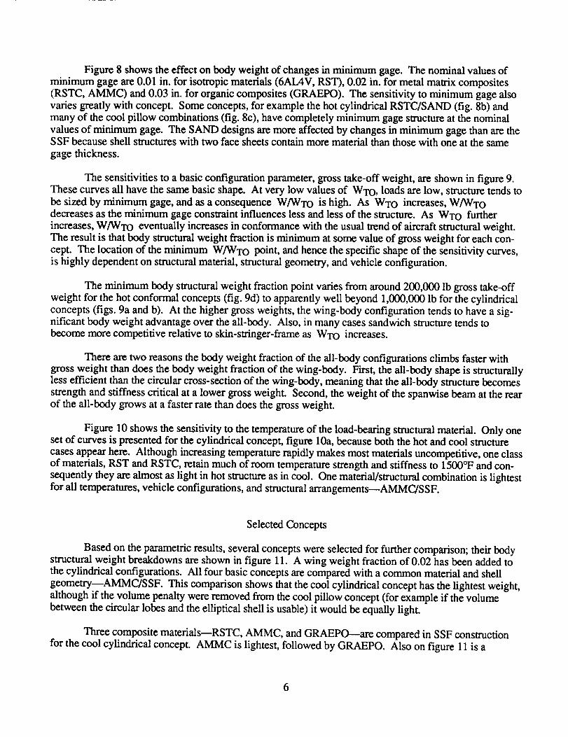
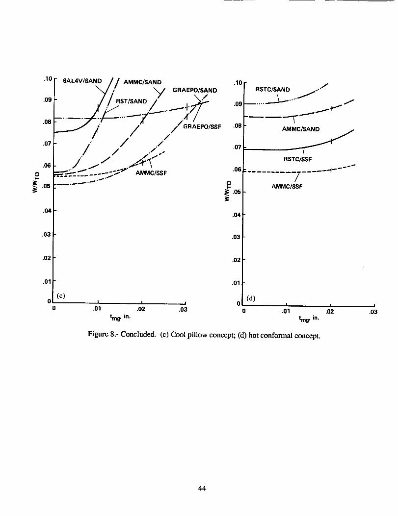
Figure8 shows the effect on body weight of changes in minimum gage. The nominal values of
minimum gage are 0.01 in. for isotropic materials (6AL4V, RST), 0.02 in. for metal matrix composites
(RSTC, AMMC) and 0.03 in. for organic composites (GRAEPO). The sensitivity to minimum gage also
varies greatly with concept. Some concepts, for example the hot cylindrical RSTC/SAND (fig. 8b) andmany of the cool pillow combinations (fig. 8c), have completely minimum gage structure at the nominal
values of minimum gage. The SAND designs are more affected by changes in minimum gage than are theSSF because shell structures with two face sheets contain more material than those with one at the same
gage thickness.
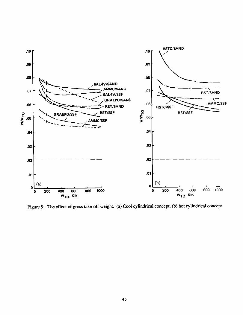
The sensitivities to a basic configuration parameter, gross take-off weight, are shown in figure 9.
These curves all have the same basic shape. At very low values of WTO, loads are low, structure tends to
be sized by minimum gage, and as a consequence W/WTo is high. As WTO increases, W/WTodecreases as the minimum gage constraint influences less and less of the structure. As WTO further
increases, W/WTo eventually increases in conformance with the usual trend of aircraft structural weight.The result is that body structural weight fraction is minimum at some value of gross weight for each con-
cept. The location of the minimum W/WTo point, and hence the specific shape of the sensitivity curves,is highly dependent on structural material, structural geometry, and vehicle configuration.
The minimum body structural weight fraction point varies from around 200,000 lb gross take-off
weight for the hot conformal concepts (fig. 9d) to apparently well beyond 1,000,000 lb for the cylindrical
concepts (figs. 9a and b). At the higher gross weights, the wing-body configuration tends to have a sig-nificant body weight advantage over the all-body. Also, in many cases sandwich structure tends to
become more competitive relative to skin-stringer-frame as WTO increases.
There are two reasons the body weight fraction of the all-body configurations climbs faster with
gross weight than does the body weight fraction of the wing-body. First, the all-body shape is structurallyless efficient than the circular cross-section of the wing-body, meaning that the all-body structure becomes
strength and stiffness critical at a lower gross weight. Second, the weight of the spanwise beam at the rearof the all-body grows at a faster rate than does the gross weight.
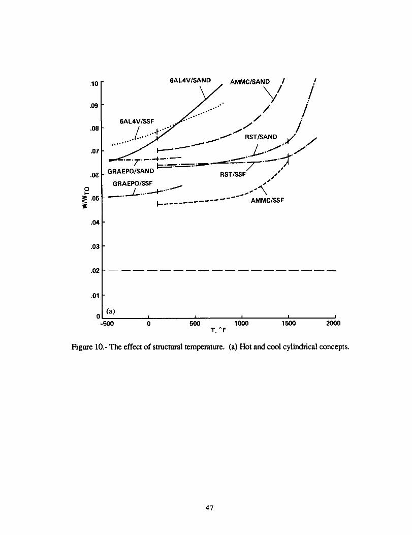
Figure 10 shows the sensitivity to the temperature of the load-bearing structural material. Only oneset of curves is presented for the cylindrical concept, figure 10a, because both the hot and cool structure
cases appear here. Although increasing temperature rapidly makes most materials uncompetitive, one classof materials, RST and RSTC, retain much of room temperature strength and stiffness to 1500°F and con-
sequently they are almost as light in hot structure as in cool. One material/structural combination is lightestfor all temperatures, vehicle configurations, and structural arrangementsmAMMC/SSF.
Selected Concepts
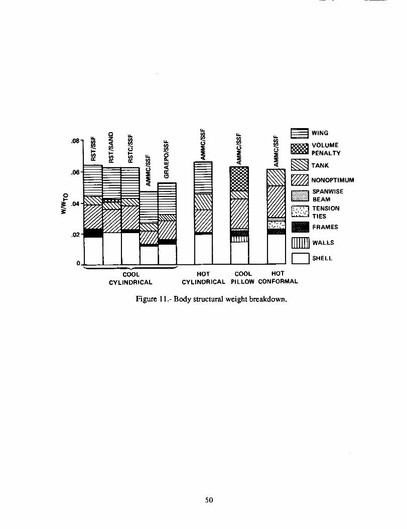
Based on the parametric results, several concepts were selected for further comparison; their bodystructural weight breakdowns are shown in figure 11. A wing weight fraction of 0.02 has been added tothe cylindrical configurations. All four basic concepts are compared with a common material and shell
geometry--AMMC/SSF. This comparison shows that the cool cylindrical concept has the lightest weight,
although if the volume penalty were removed from the cool pillow concept (for example if the volume
between the circular lobes and the elliptical shell is usable) it would be equally light.
Three composite materials--RSTC, AMMC, and GRAEPO---are compared in SSF construction
for the cool cylindrical concept. AMMC is lightest, followed by GRAEPO. Also on figure 11 is a
6

comparisonof thesamematerial,RST,in bothSSFandSANDfor thesamevehicleconfigurationandstructuraltemperature.TheSSFstructurehasframesbut theSANDdoesnot andtheSAND hasavolumepenaltybut theSSFdoesnot; thenetresultis aboutequalweightfor both.
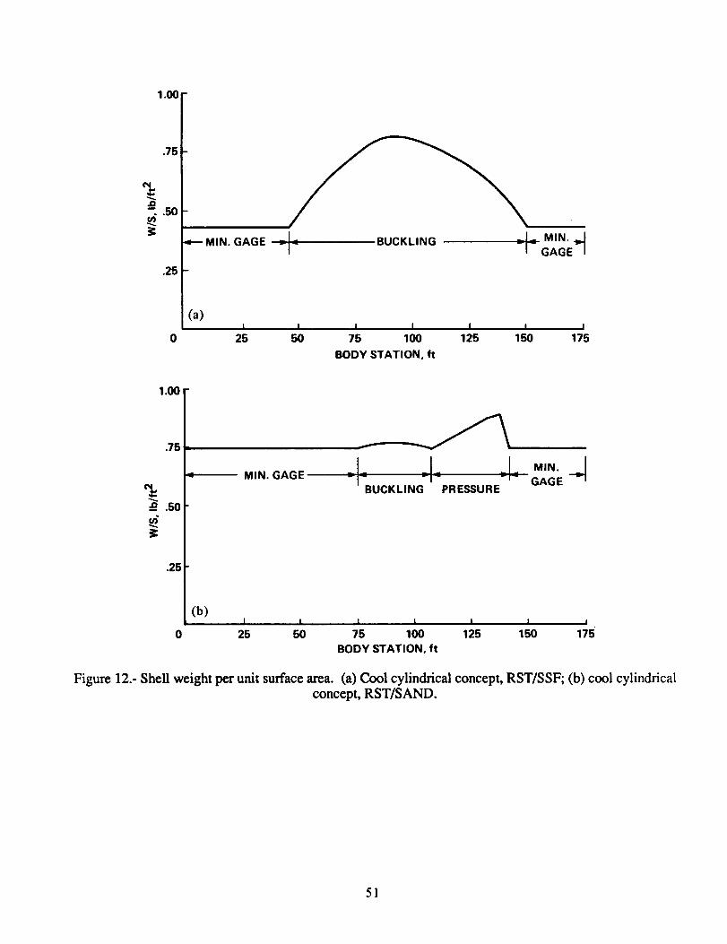
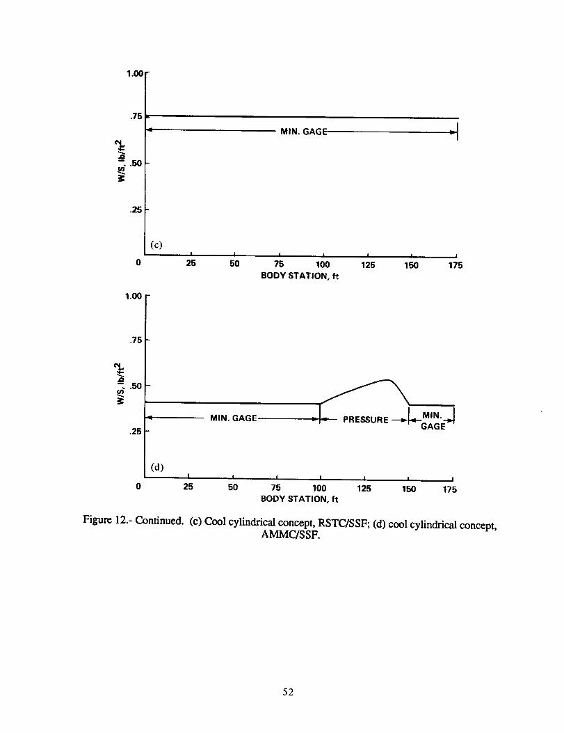
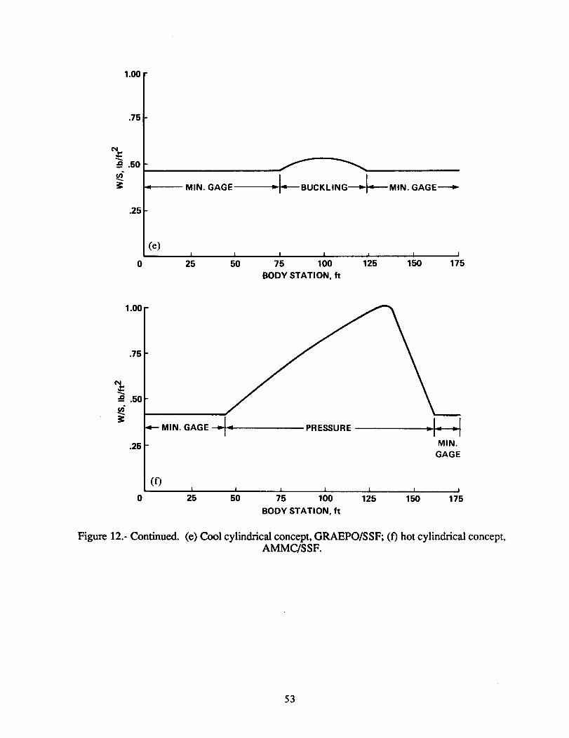
Thelongitudinaldistributions of shell weight per unit surface area for the concepts of figure 11 are
shown in figure 12. One of these concepts is buckling dominated (cool cylindrical RST/SSF), two are
pressure dominated (hot cylindrical AMMC/SSF), and the other five are heavily influenced by the mini-
mum gage constraint. One concept, cool cylindrical RSTC/SSF, is entirely minimum gage. These results
are consistent with the parametric trends discussed earlier. Figure 12 also shows that minimum gages are
highest for sandwich structure, relative to skin-stringer, and for composite materials, relative to isotropic.
The relatively low density of the AMMC material makes it light in minimum gage, even though it is acomposite.
CONCLUDING REMARKS
Part I of the hypersonic body weight study has identified several important characteristics and
trends. It was found that, generally, the wing-body designs had lower load-bearing body weights than did
the all-bodies; this is because the wing-body shape has efficient circular cross-sections, as opposed toelliptical, and lower surface area for the same volume. It was also found that skin-stringer-frame con-
struction gives lighter weight than sandwich construction, especially for composite materials. This lighterweight is due to the relatively low bending loads on the vehicles (which is due, in turn, to low gross
weight and density) and, in the case of composite materials, to high minimum gages. The exception is thepillow tank arrangement, which tends to be lighter in sandwich. The use of metal matrix compositesmakes hot structure competitive with cool.
The relative importance of design pressure and of minimum gage constraints is highly dependent
on vehicle/structural/material combination. For some combinations, the nominal design pressure of 15 psidominated the sizing of structural dements but for others it was insignificant. While minimum gage had at
least some degree of impact on all designs, some designs were completely minimum gage. These results
indicate that hypersonic aircraft structure should be designed with new considerations in mind. Proper
selection of structural concepts and materials and careful attention to detail design should largely eliminatethe effects of pressure, minimum gage, and thermal stress (the latter not considered in this study).
The body weight of hypersonic vehicles has a characteristic trend with respect to changes in gross
take-off weight. Body weight is high at low gross weights (due to minimum gage effects) and high at
high gross weights with a minimum body weight at some intermediate value of gross weight. The mini-
mum weight point, however, is very different for the various concepts. Minimum body weight for all-
body shapes occurs from 200,000 lb to 700,000 Ib gross weight, and for wing-body shapes, it can bewell over 1,000,000 lb. The implications are that the wing-body configuration becomes increasingly
superior, from a structural standpoint, as gross weight increases and that selection of the best structural
concept/material is highly dependent on gross take-off weight.
Varying the temperature of the structural material gave the result that the combination of advanced
metal matrix composite material in skin-stringer-frame construction (AMMC/SSF) gave the lightest weight
for all structural/vehicle concepts and all temperatures. Close competitors for the cool and hot cylindrical
concepts (wing-body shape) were graphite expoxy and advanced isotropic titanium alloy, respectively,
7

bothin skin-stringer-frameconstruction.Fortheall-bodyshape(coolpillow and hot conformal con-cepts), there were no close competitors to the AMMC/SSF combination.
The primary purposes of Part I of the hypersonic body weight study were to study weight trends
and to identify promising concepts for further study. In Part II, we will further investigate these concepts
by adding thermal protection system weight and by changing structural concept and material along thevehicle length to better match local geometric, load, and temperature conditions. We will also further
investigate hot vs. cool structure and take up the question of integral vs. nonintegral tanks.
8
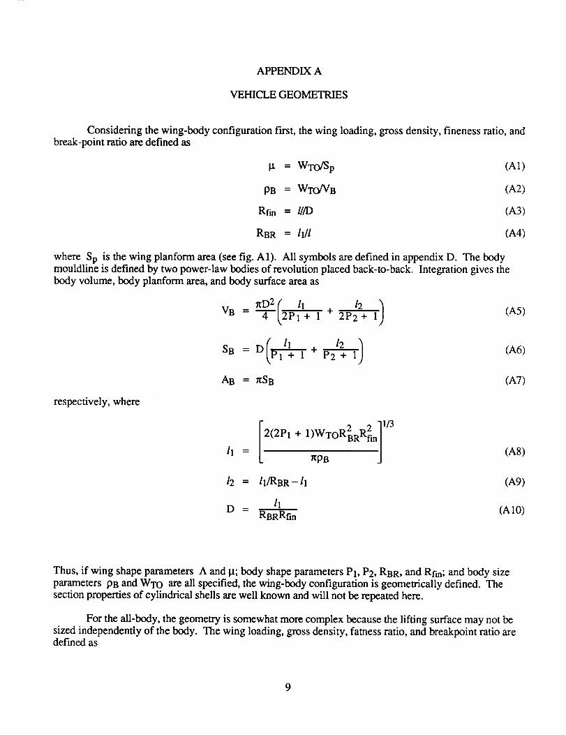
APPENDIX A
VEHICLE GEOMETRIES
Considering the wing-body configuration first, the wing loading, gross density, fineness ratio, andbreak-point ratio are defined as
I.t = WTO/Sp (A1)
PB = WTO/VB (A2)
Rfin = l[/D (A3)
RBR = 11]1 (A4)
where Sp is the wing planform area (see fig. A1). All symbols are defined in appendix D. The bodymouldline is defined by two power-law bodies of revolution placed back-to-back. Integration gives the
body volume, body planform area, and body surface area as
7rD2 (. /1. 12 )VB = 4 _2P1+ 1 + 2P2+ 1(A5)
ll 12 .)SB = D P1 + 1 + P2+-----T (A6)
AB = /rSB (A7)
respectively, where
ll
2 2 "]1/3
2(2P1 + 1)WTORBRRfin. I
-j (A8)
/2 = ll/RBR-I1 (A9)
llD =RBRRfin (A10)
Thus, if wing shape parameters A and It; body shape parameters P1, P2, RBR, and Rfin; and body size
parameters PB and WTO are all specified, the wing-body configuration is geometrically defined. The
section properties of cylindrical shells are well known and will not be repeated here.
For the all-body, the geometry is somewhat more complex because the lifting surface may not besized independently of the body. The wing loading, gross density, famess ratio, and breakpoint ratio aredefined as
9
tx = WTO/Sp (All)
PB = WTONB (A12)
Rfat = S_Sp (A13)
RBR = ln]l (A14)
where Sp is the body plan area and Sn is the cross-sectional area at the breakpoint (Sn is also the maxi-mum cross-sectional area if 0.5 < RBR < 1.0). With the aid of figure A2, the body plan area, breakpoint
cross-sectional area, volume, and body angle are computed to be
Sp = /2/tan A (A15)
Sn = nl_/tan A tan _ (A 16)
VB = rd_l(l + I_)/6 tan A tan 13 (A17)
= tan-I (_R2BR/Rfat) (AI8)
Inspection of equations (A11) through (A18) shows that the all-body geometry will be defined if the shape
parameters A, Rfat, and RBR ,and the size parameters PB and WTO are specified. Expressing the lengthin terms of these parameters gives
l = [6RBRWTO tan A/(1 + RBR)RfatPB] 1/3 (A19)
so that the length of the all-body scales with (WTO/PB) 1/3 for constant shape, just as it does for the wing-
body. The wing loading of this configuration in terms of the configuration parameters is
TO(1 + RBR)2R2atp2tan A
)
IX = 36R2 R (A20)
This relation is plotted for A = 75 °, RBR = 0.67, and Rfat = 0.09 in figure A3. The ellipse ratio a/b of
the forebody is given by
afo = _R2R cot A/Rfat (A21)
The section properties of elliptical shells will be needed for the weight analysis. If the semimajor
and semiminor axes of the shell at a certain longitudinal station are a and b, respectively, then the cross-
sectional area and perimeter are given by
A = nab (A22)
P = 4aEr_ (A23)
The moment of inertia about the y axis divided by the shell thickness is found from
10
= Iv = 4 l/az2 dsI'
Y is Jo
fa(_.22) q b2_,2= 4 1 - b2 1 + a2(a 2_y2) dy0
= 4able ii - (2EII3- EI) - _EI-3-zeEIIt](A24)
where EI and EII are the complete elliptic integrals of the fast and second kind, respectively, and where
e = _l-(b/a) 2 (A25)
tis the eccentricity. The following approximate expressions for P and were found to give good agree-ment with equations (A23) and (A24) for the values of e of interest: Y
P = 2xa_l - (e2/2) (A26)
I
I = (_4)ab213 + (b/a)] (A27)y
For concepts employing pillow tankage, the structure is not in the shape of the vehicle configura-tion but consists of intersecting cones fitted within the elliptical cross section of the all-body as shown in
figure A4. The number of circular sections or lobes is taken to be the nearest odd integer to
NT = 2(a/b) + 1 (A28)
This relation was determined empirically and gives minimum or near minimum weight for the configura-
tion variations considered in this study. Referring to figure A4, the equations defining the ith lobe in termsof the i-lth are
e2r_ = e2b2-d_(1-e 2) (A29)
ri sin 0i = ri-1 sin 0 (A30)
di = di-1 + ri-1 cos 0 + ri cos 0i (A31)
where equation (A29) is the condition of tangency of the circle and the ellipse. These equations are solvedsequentially at each body station x beginning with the center lobe. The free parameter 0 is available for
weight and volume optimization as discussed in appendix B. The perimeter, cross-sectional area, and I'yof the circular lobes at any section are given by
11

NT-1I ! t
Ps = gb - 2b0 + (2gri - 2ri0i - 2ri0) + 2_;rN T - 2rNT0
i=2
(A32)
[NT--1
A = 2 - _b2(20-sin20)+ i_2 _ri2- 12 ]1 r2(20i sin 20i) - _-r i(20 - sin 20)
2, 1 2 .... , 20N_)]+ _rNT - _-rNTtZUN T - sin
(A33)
!
Iy
=4b3--_(cos 0
m
!
NT-1
r i
+ T (cos 0 sin 0 + cos 0i sin 0i + _ - 0 - 0i)
m
3I
' , ,+ cos 0N T sin 0NT + _ - 0NT) (A34)
where Nr = (NT + 1)/2. The perimeter of the vertical walls connecting the lobes is given by
!
NT-1
PW = 4 sin 0 Y_ ri (A35)i=l
A typical pillow tankage installation is shown in figure A4. In view of equation (A28), the fore-
body will have a fLxed number of lobes while the number of lobes in the afterbody will increase toward the
rear of the vehicle. This increase results in an afterbody structure that is probably an impractical design foran actual vehicle but is convenient for use in a mathematical model,
12

APPENDIXB
WEIGHT ANALYSIS
In this appendix, weight estimating methods are developed for the load-carrying body structure. It
is convenient to discuss the all-body conformal and pillow-tank concepts separately. The wing-body
weight equations are obtained as a special case of the all-body conformal equations. Weight estimationrelationships for integral and nonintegral tanks, for the span-wise beam used with the all-body shape, and
for the nonoptimum weight are also presented. In addition, the volume taken up by the body structure isdetermined.
Body Structural Weight for Conformal Concepts
Considering f'trst the elliptical shell, the stress resultants in the axial direction caused by longitudi-
nal bending, axial acceleration, and pressure at a station x are
MbNXB = "-r- (B1)
IY
NxWs (B2)NXA = p
Nxp = _ (B3)
respectively. In equation (B2), Ws is the poraonof vehicle weight ahead of station x if x is ahead the
inlet entrance, or the portion of vehicle weight behind x if x is behind the nozzle exit. In equation (B3),
Pg is the tank design pressure for integral tank concepts, whereas it is a nominal value of 2 psi for nonin-tegral tank concepts. The total tension stress resultant is then
N + = NxB + Nxpx
(B4)
if x is ahead of the nozzle exit, and
'4-
N x = NxB + Nxp+ NXA (B5)
if x is behind it. Similarly, the total compressive stress resultant is
°' fnotpros urosta ilize }xP, if stabilized(B6)
if x is ahead of the inlet entrance, and
0, if not pressure stabilized tN x = NXB- Nxp, if stabilized(B7)
13

if x is behindit. Theserelationsarebasedon thepremise that longitudinal acceleration and pressure
always increase the magnitude of stress resultants; acceleration loads never decrease stress resultants, but
pressure loads may relieve stress, if pressure stabilization is chosen as an option. The pressure stabiliza-tion option is available only for integral tankage. The stress resultant in the hoop direction is
Ny = bPgKp (B8)
where Kp accounts for the fact that not all of the shell material (for example, the core material in sand-wich designs) is available for resisting hoop stress. Expressions for the geometrical quantities I'y, A, and
P may be found in appendix A.
The equivalent isotropic thicknesses of the shell are given by
tSc = Nx/FCy (B9)
tST = (1/Ftu)max( N+, Ny) (BIO)
tSG = Kmgtmg (Bll)
for designs limited by compression, tension, and minimum gage, respectively. In equation (B 11), tmg is
a specified minimum material thickness and KmgiS a parameter relating tSG to tmg which depends-onthe shell geometry. A fourth thickness that must'be considered is that for buckling lifiaited designs, tSB, asgiven by equation (C13).
At each fuselage station x, the shell must satisfy all failure criteria and meet all geometric con-straints. Thus, the shell thickness is selected according to
ts = max(tSc, tST. tsG. tSB) (BI2)
If iS = tSa, the structure is buckling critical and the equivalent isotropic thickness of the frames, tF, is
computed from equation (C13). If ts > ts_, the structure is not buckling critical at the optimum framesizing and the frames are re-sized to make tS = tSB. Specifically, a new frame spacing is computed from
equation (C2) as
d = -- (B13)N-
x
and this value is used in equation (C11) to determine tl:.
Reference 5 shows that for pressures as low as 2 psig the pressure-induced bending loads at the
ends of the semi-major axes of the elliptical shell result in prohibitively high weight, even for concepts that
take these loads in ring-frames. Consequently, it is assumed that these loads are taken by internal vertical
tension ties, for both integral and nonintegral tankage. At a fuselage station x, the equivalent isotropicthickness of the "smeared" tension ties is given by
14

APiT = _ (B14)
lt'tU
The total thickness of the body structure is then
tB = ts + tF + tT
The shell gage thickness, if desired, may be computed from tg : [s/Kmg.weight is obtained by summation over the vehicle length
(P[si + pFtFi + PF[Ti) ai "_ 1 - (ei2/2) Axi (B16)wi 2g Z
where quantifies subscripted i depend on x. The procedure just described simplifies to the special caseof circular cross-section vehicles in an obvious way; tension ties are not needed with circularcross-sections.
We next discuss the derivation of the structural geometry parameters shown in table B 1. The
Z-stiffened shell will be used as an example of skin-swinger-frame construction. Using reference 9 and
figure B 1, the equivalent isou'opic thickness of the smeared skin and swingers is
is = ts+"b-_s _- 1 + 1.6 ts (BI7)ts)J
Since only the skin is available for resisting pressure loads,
Kp = 1+ 1.6(_s) t(_-s) (B18)
For minimum gage designs, if ts > tw t hen tw = tmg and
is = [ t(_w)+ 1.6 (_'_)ltmg (B19)
so that
Kmg =
On the other hand, if ts < tw then ts = tmg and
is = [1
so that
(B15)
The "ideal" body structural
t(Fw) + 1.6 b(_s) (B20)
+ 1.6 (_s) (_)]tmg (B21)
('bw'_ (tw_Kmg = 1 + 1.6t-b_-s)t_--s) (B22)
15
Equations (B 18), (B20), and (B22) show that for both pressure loading critical and minimum gage limitedstructure, (bwfos) and (tw/ts) should be as small as possible (i.e. no stringers).
In practice, a typical design will be influenced by bending and pressure loads and by the minimum
gage constraint, and thus a compromise is necessary. If buckling is of paramount importance, then a goodchoice is (bw/bs) = 0.87 and (tw/ts) = 1.06 because this gives the maximum buckling efficiency for thisconcept, e =.911 (ref. 9). From equations (B18) and (B22),
Kp = King = 1 + (1.6)(0.87)(1.06) = 2.475
This is concept 2 in tables 4 and B 1. If pressure is a dominate loading condition, then (bw/bs) = 0.6 and
(tw/ts) = 0.6 is a reasonable choice, giving _ =.76, Kp = 1.576, and Kmg = 2.638; this is concept 3. For
minimum gage dominated structure, the geometry (bw/bss) = 0.58 and (tw/ts) = 0.90 gives concept 4.
The geometry of the truss-core sandwich shell concept is shown in figure B2. The equivalentisotropic shell thickness of this concept is
1)tf cos V f (B23)
Reference 9 shows that optimum buckling efficiency is obtained for (tc/tf) = 0.65 and V =55 °. This gives
e = 0.4423, Kmg = 4.820, and Kp = 3.132, concept 6 in tables 4 and B1. To get a design that is lighterfor pressure and minimum gage dominant structure, we choose a geometry that puts more material in the
face sheets and less in the core; the choice (tcJtf) = 1.0 and V = 45 ° gives structural concept 7. These
calculations assume that the face sheets and core are the same material and are subject to the sameminimum gage constraint.
The preceding analysis may be used to estimate the relative weights of elliptic and circular shells inbending. Consider an elliptical and a circular shell each of equal length and equal enclosed cross-sectional
area. Let the structure of both shells be a frame-stabilized, integrally stiffened shell of the same material
which is buckling critical, and suppose each shell to be loaded by the same bending moment (no pressureloading). Then, for the elliptical shell, equations (B16) and (C13) give
WIellipse = npa 1- _ A x
×
Setting r = a = b in this expression gives
÷06 81a ]
W_ircle(2/rpr Ax) (.LK-----_Ie3 J
_(2r 2) 1/4
Using equation (B1) and setting r = _ the weight ratio is then
16

0324)
Thisratio, which is afunctiononly of a/b, is plotted in figure B3. It is seen to be nearly linear--the ellip-
tical shell being about twice as heavy as the circular one at a/b = 4. If the shells are constructed of truss-core sandwich, equations (B16), (B1), and (C1) result in the ratio
Wlellips¢ e 2 4 _3/5Wlcircle = ('_ "_ 1 - "_'{[3 + (b/a)l(a/b)3/2J
0325)
This ratio is also plotted in figure B3 and also varies linearly with a/b but with a steeper slope. Since all-
body configurations typically have a/b = 4, conformal structure elliptical cross-section concepts will be
considerably heavier than circular cross-section concepts.
Body Structural Weight for Pillow Concepts
Because of the poor structural efficiency of elliptical shells, a special concept called pillow tankage
is potentially attractive for all-body configurations. This concept consists of a shell composed of inter-
secting cones fitted within the elliptical body, as discussed in appendix A. The stress resultants in the cir-
cular lobes are computed according to formulas (B 1) through (B8), except that equations 032) and (B3)
are replaced by
nxWs 0326)NXA = (Ps + Pw)
APgNxp = (Ps + Pw) 0327)
The various equivalent isotropic thicknesses of the shell are computed from equations (B9) through (B 11)
as before, and the shell thickness is selected from equation 0312). Any structural shell geometry listed in
tables 4 and B 1 can be used in pillow tankage; the buckling relations for these concepts may be determinedfrom appendix C. Frame weights are computed from either equation 0313) or equation (C13), depending
on whether or not the design is buckling critical.
The maximum stress resultants on the vertical walls connecting the pillow tank lobes are
APNwx = (Ps + _w) 0328)
Nwz = Pg(b cos 0 + r2 cos 02) 0329)
The equivalent isotropic thicknesses of the wall are given by
twT = F+u max(Nwx , Nwz) 0330)
twG = Kmgtmg 0331)
17

for designs limited by tension and minimum gage, and the wall thickness is therefore
tw = max(fwr, twG) (B32)
The ideal structural weight of pillow tankage vehicles is then obtained by summation over the body length
WI = Z[PPsitsi + pF(Ps i + Pwi){Fi + PFPwi{wi]Axi (B33)
where quantities subscripted i depend on x.
The parameter 0 (fig. A4) is available for vehicle performance optimization. The function WI(0)
monotonically decreases within the range 0.< 0 < x/2, and 0 therefore should be as large as possible to
minimize WI. (Although it is possible for equation (A28) to restrict the range of 0, this limitation is notgenerally encountered.) However, as 0 approaches x/2 the tank volume decreases (recall that the num-
ber of lobes, NT, is fixed by equation (A28)) and thus the volumetric efficiency ri, defined as the ratio of
tank volume to body configuration volume, must be considered as well as WI. For practical designs,ri(0) is a concave downward function having a local maximum for some value of 0 on 0 < 0 < x/2.
The payload performance of a hypersonic vehicle, _, will be a function of both W! and 11, that is,= (WI, ri); hence the rate of change of payload with respect to 0 is
d* ( 2" "_dWI (2"_ dTI
0-'a": '+ C -J00 (B34)
The necessary condition for maximum _ gives to a first-order approximation
(Wlopt - WIo) + (riopt - rio) = 0 (B35)
where _/_WI and _/'Orl are the sensitivities of payload to W I at constant ri and to 11 at constant
WI, respectively, and where WIo and rlo are nominal values. Values of the partial derivatives are deter-
mined from a sensitivity study performed with a mission analysis program. Equation (B35) is solved for
the optimum values WIotx and riopt using Newton's method with O as the independent parameter. Fortypical vehicle shapes an'd missions, this procedure gives values of 0 from 50 ° to 60 °.
Nonoptimum Body Structure Weight
Since the above analysis gives only the ideal weight, Wi, the "nonoptimum" weight (fasteners,
cutouts, surface attachments, uniform gage penalties, manufacturing constraints, etc.) has yet to be deter-
mined. The method used here is explained with the aid of figure B4 which is a log-log plot of body
weight as a function of a weight estimation parameter, X, which accounts for the effects of gross weight,
body dimensions and design load factor. The circles on the figure indicate actual body weights of existingaircraft. The lower line represents the equation developed in reference 10 to estimate body weight of
wing-body hypersonic aircraft, and reflects improvements over time in design techniques and analysismethods.
The analysis developed in the present study was applied to the same existing aircraft and the
resulting ideal weights are shown by the triangles. A two parameter regression analysis based on ideal
18

weight,WI, andbodysurfacearea,AB, was then employed to obtain the best fit with the advanced tech-
nology hypersonic aircraft line. The resulting body weights are shown by the squares, and the totalweight of the body structure is 1.637WI + 0.076AB so that the weight of the nonoptimum material is
WNO = 0.637Wi + 0.076AB 0336)
The correlation with existing aircraft is quite good (fig. B4) except for the aircraft at the extreme values of
the weight parameter. This conclusion follows from the fact that the scatter of the square symbols about
the lower curve is in the same pattern as the scatter of the circles (actual weights) about the upper curve.
Tank and Spanwise Beam Weights
To a fast approximation, the weight of a pressurized fuel tank will be proportional to tank material
density, tank pressure, and tank volume, and inversly proportional to tank material tensile strength. Thus,the weight of nonintegral tanks is given by:
WTK = 14460 pTKPgVTK 0337)FtUTK
The proportionality constant has been determined from the weight of the tank described in reference 11.
For this tank, 9TK = 0.298, FtUTK = 172,000, VTK = 71,500, Pg = 15.3, and WTK = 27,400.
For integral tank concepts, the tank weight consists only of bulkheads and other items specificallynecessary for containment of fuel within the body structure. Again using the tank of reference 11, as areference point, for integral tanks
WTK = 2406 PP_VTKFtu 0338)
Because these formulas are based on an actual tank design, nonoptimum factors are not applied to tankweight.
Comparison of equations 0337) and 0338) shows that for the same materials and operatingtemperature and pressure, the nonintegral tank weight will be approximately six times the integral tank
weight. This advantage for integral tankage is greatly reduced or eliminated, however, because in integraltankage concepts the tank pressure loads must be carried in the body structure, typically an inefficient
pressure vessel, and also because the tank components typically must operate at higher temperatures.
The transverse bending moments associated with the large span at the rear of the all-body configu-
ration require additional structure for this configuration. The weight of such structure is estimated by
computing the weight of a spanwise beam capable of transmitting the horizontal tail loads into the bodystructure. The result is
WSB = 9.822pLTa2/dTFcy 0339)
where LT is the vertical tail normal force at the design load factor, dT is the beam depth (taken to be the
body depth at the location of the tail), and aM is the beam span (taken to be the body span at the location
19
of thetail). Thesamenonoptimumfactorthat is applied to the body structure, 1.637, is included in equa-
tion (B39).
Structural Volume
The mission performance of hypersonic aircraft is sensitive to volume as well as to weight. Con-
sequently, the volume taken up by the structure must be estimated and factored into mission performance
calculations and design concept decisions. For the concepts considered here, there are two sources of lost
volume due to the structure. The first is the volume between the lobes of the integral tank structure and the
vehicle mouldline in the pillow tank concept (see fig. A4). At a station x, the difference between the area
enclosed by the mouldline and the area enclosed by the pillow tankage is
AA = ltab- A (B40)
where A is given by equation (A33). The volume decrement (lost volume) is then given by
VAp = ZAAi Axi.
The second source of lost volume is the space between the face sheets of sandwich shells. From
figure B2,
h = -_tan_g (B41)
and from reference 9,
bf = 0.95tf KxtE (B42)
provided N x > 0. Substituting tf = {/Kp and equation (B42) into equation (B41) gives
(B43)
where
Kth - 0.95 K'f-K_xtan _g2Kp (B44)
For concept 6 in table B1, Kx = 3.5, _ -- 55 °, and Kp = 3.132; this gives Kth = 0.405 as shown intable B1. At a station x, the cross-sectional area enclosed by the structure is AA = Ph where P is the
perimeter of the structural shell, given by equation (A23) or equation (A26). The volume decrement is
then VAs = gAtq Axi as before.
After the pillow tank volume decrement (if any) and the slructural shell volume decrement (if any)
have been added to get the total volume lost because of the structure, VA = VAp + VA s, the volumetricefficiency is determined from r I = 1-VA/VB. The weight penalty from lost volume is then
20

c3_/o_q (11 - 1) (B45)Wa = _/aWl
This "weight" should be included when comparing different structural concepts, in order to properly
reflect the impact on mission performance. The partial derivatives in equation (B45) are the same as those
in equation (B34) and are highly mission dependent.
21

APPENDIX C
BUCKLING EQUATIONS
In this appendix expressions are derived for the equivalent isotropic thickness of the shell requiredto preclude buckling, tSB, and for the "smeared" equivalent isotropic thickness of the ring frames required
to preclude general instability, tF. The expressions are derived for the elliptical shell of the all-body con-
figuration; these expressions are then used to obtain the equations for cylindrical shells as a special case.The major assumptions are that the structural shell behaves as an Euler beam and that all structural materi-als behave elastically.
For the frame-less sandwich shell concept, it is assumed that the elliptical shell buckles at the load
determined by the maximum compressive stress resultant N_, on the ellipse. Reference 12 indicates that agood approximation is obtained by assuming the structure to'be a circular cylinder with the same radius ofcurvature as that of the ellipse at the point of application of N-. Since the maximum load occurs at the
ends of the minor axis where the radius of curvature is a2/b, trhe buckling equation is
(a2/b) E = e L(a2/b)j
or, solving for tSB
V Yx ]I/m
= (a2/b)L(a2%S j (C1)
This equation is based on small deflection theory, which seems reasonable for sandwich cylindrical shells,
although it is known to be inaccurate for monocoque cylinders. Values of m and e may be found, for
example, in references 9 and 13-15 for many shell geometries. Table B1 gives values for structural con-
cepts number 6 and 7 used in the present study, both of which are truss-core sandwich (see table 4). The
quantities N', a, b, r, and consequently tSB, will vary with body station dimension x. For the wing-.Xbody, equation (C1) becomes
lNx] l/m
iSB = rt_ ) (CI')
For the stiffened shell with frames concept, the common procedure of assuming the shell to be awide column is adopted. The buckling equation is then (ref. 13)
x
_"=e
or, solving for tSB
22

N'd
tSB = (C2)
which is applicable for both the all-body and the wing-body. Values of e for structural concepts 1
through 5 are given in table B1; The structural shells are simply stiffened, Z-stiffened, and truss-coresandwich. We next size the frames to prevent general instability failure.
In order to generalize the Shanley criterion (ref. 16) for frame sizing to elliptical shells, the stiff-
ness of elliptical rings to inplane loads must be determined. If the methods and nomenclature of reference17 are used, the redundant bending moment at the ends of the semimajor axis of an elliptical ring due to
oppposing inplane point loads of magnitude L acting perpendicular to the ring at the ends of the semi-minor axis is
fs M' ds L
Ma = iSds _.-a
0
q a - a2y 2 + b2]¢ 2 La2(a 2 _ y2) dy -
(C3)
where the dimensional quantities are defined in figure 24 and
Em = 1 + lo_e[(a/b)(1 + e)] (C4)(a/b)2e
The bending-moment distribution in the ring, therefore, is given by
LaM = "_'_,E'ff'a- 2 (C5)
To determine the deflection of the ring at the point of application of the load, the method of virtual work isused:
f s M(OM/OL) ds8 = 2 EFIF
2L fa aE/_E'_H _q b2_'2= _ - I + a2(a 2_y2) dy0
I6- + 6e 2 - (C6)
23

Since L = KS/S,thespringconstantof thering is
K3EFIFI_- 1 )KS = (C7)
the factor (K3/8)[(x/8) - (l/x)] being added to conform to reference 16.
It is of interest to compare the stiffness of an elliptical ring to that of a circular ring. For equal val-ues of EFI F and equal enclosed areas (r = -_ ), the ratio of spring constants is
(K_)¢llivse =(KS)circle
2EII- El EI - EI! E2m
3 + 3e 2 -
(C8)
This ratio is plotted as a function of a/b in figure C1, and the relatively low spring constant of the ellipti-
cal ring at the values of a/b of interest indicates that the weight of the rings in elliptical shells will be
greater than those of circular shells for the same conditions.
The equation for frame (ring) weight is next established. Generalizing the results of reference 16
to elliptical frames gives the following expression for the spring constant required of the frames
K1K2aEIIN-X
KS = d (C9)
If the frames are "smeared" according to A F - iFd, then combination of equations (C7) and C9) gives
iF = 4CFNxa4EII/2EII3- EI+ EI 3e2EII _ 4-_)(CIO)
where KF1 (= IF/A 2) is the frame stiffness, and where the constants K1, K2, K3 have been absorbed by
"Shanley's constant,-" CF, taken to be 0.625x10 --4. Calculations show that the expression
iF = _/xCFNx/KFld3EF _/3 + (b/a) (0.3719ab + 0.6281a 2) (C11)
very closely approximates equation (CIO) for the range of a/b of interest and equation (C11) is used inthe weight analysis.
24
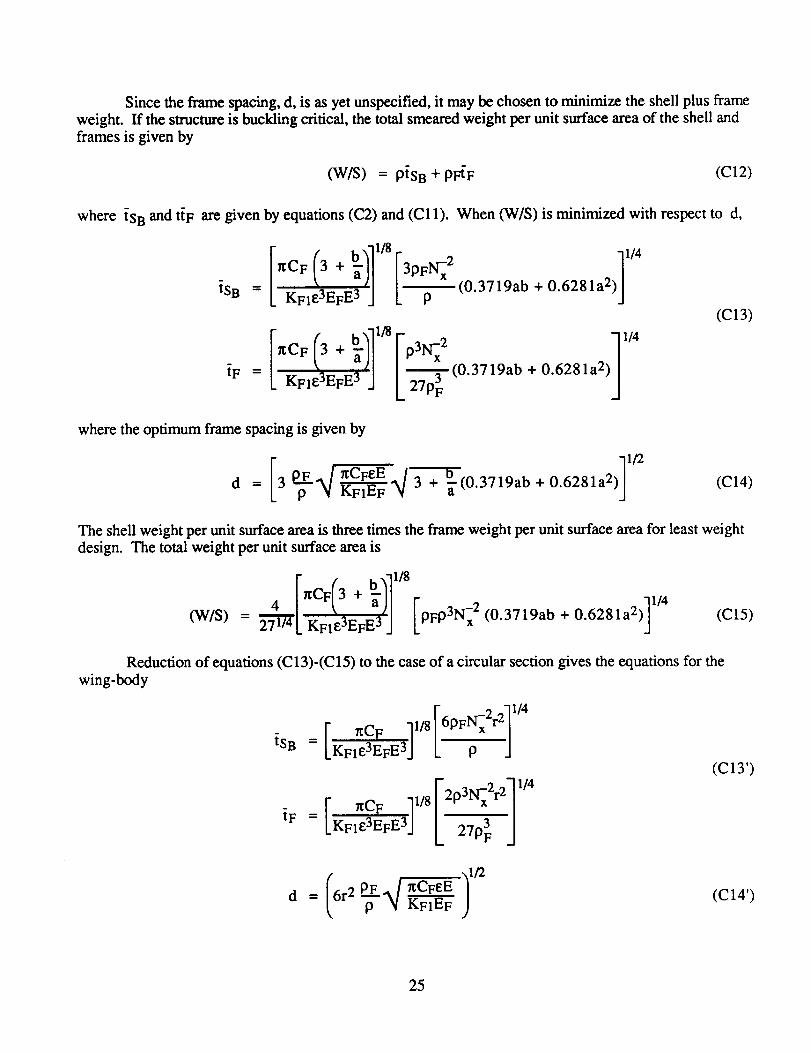
Sincetheframespacing,d, is asyetunspecified,it maybechosento minimizetheshellplusframeweight. If thestructureis bucklingcritical, thetotalsmearedweightperunit surfaceareaof theshellandframesis givenby
(W/S) = ptSB + pFtF (C12)
where tSB and ttF are given by equations (C2) and (C11). When (W/S) is minimized with respect to d,
tSB
tF =
= L KFl133EF E3 ] ' P(0.3719ab + 0.6281a2)] TM
J k27p3F (0.3719ab + 0.6281a 2)
(C13)
where the optimum frame spacing is given by
]n:CFeE 4 3+'_-(0.3719a b + 0.6281a2 >d= 3 (C14)
The shell weight per unit surface area is three times the frame weight per unit surface area for least weight
design. The total weight per unit surface area is
= _ hCF 3 + [(W/S) 271/_L KFle3EFE 3 j pFO3Nx 2 (0.3719ab + 0.6281a2)] TM (C15)
Reduction of equations (C13)-(C15) to the case of a circular section gives the equations for the
wing-body
r -2 .'11/4r _CF 11/8
iSB = LKFIE3EFE3j [6pF--_x rz-J
[" nCF ]l/8 r2p3N-xxZr2] 1/4
tF = LKFle3EFE3"] L J
(C13')
: (C14')
25

is b.
( 2 "_1/4r _CF ]1/8 r 2 _11/4
(w/s) -- 4(r/.) /KF,_aEFE3j ,-,-j <c,,.,
For the pillow tank geometry, figure A4, the maximum load occurs where the radius of curvatureTherefore, for sandwich shell,
IN x ]l/m
_s. = b[b-_)For the frame stiffened shell concepts, the bucking equations are
=[ CFbI_ ]l/sr 2"11/4
[ CFbIy ]1/8 [2p3N-xx21 TM
1/2
d = (6 pP-pE'4bI_-_4gCFeE__)
cFb,;1"8111,,(W/S) = 4 _2"_') LKFle3EfE3J
is given by equation (A34).where I'Y
(CI")
(C13")
(C14")
(C15")
26

APPENDIXD
SYMBOLS
A
Aa
AF
a
aM
b
bs
bM
bw
CF
D
d
di
dT
E
EF
EI
Eli
EIII
e
Fcy
Ftu
cross sectional area
body surface area
frame cross-sectional area
semimajor axis
maximum semimajor axis
semiminor axis
stiffener _spacing, figure B 1
maximum semiminor axis
stiffener depth, figure B 1
Shanley's constant
maximum diameter of wing-body
frame spacing
defined on figure A4
body depth at vertical tail
Young's modulus of shell material
Young's modulus of frame material
complete elliptic integral of first kind
complete elliptic integral of second kind
defined b y equation (C4)
eccentricity, defined by equation (A25)
compressive yield strength
tensile ultimate strength
27
h
IF
Iy
I'y
KF1
Kmg
Kp
KS
Kth
LT
1
ll
12
M
m
Nx A
NXB
Nxp
NT
Nw x
Nwz
N +x
N-X
Ny
thickness of sandwich shell, figure B2
frame cross-section moment of inertia
moment of inertia about y axis
Iy/ts
frame stiffness coefficient, IF/A 2
shell minimum gage factor;, see equation 0311)
shell geometry factor for hoop stress
flame spring constant
sandwich thickness parameter
maximum vertical tail lift
body length
forebody length
afterbody length
distance to breakpoint; see figure A2
longitudinal bending moment
buckling equation exponent
defined by equation (B2)
defined by equation (B 1)
defined by equation (B3)
defined by equation (A28)
axial stress resultant in wall
vertical stress resultant in wall
tensile axial stress resultant
compressive axial stress resultant
hoop direction stress resultant
28

nx
P
Pg
Ps
Pw
P1
P2
RBR
R fat
Rfin
r
ri
Sp
Src
T
tc
tf
ts
tg
tw
tmg
_B
_F
longitudinal acceleration
perimeter
internal gage pressure
perimeter of shell
perimeter of walls
exponent of power law of forebody of wing-body; see figure A1
exponent of power law of afterbody of wing-body; see figure A 1
breakpoint ratio, defined by equations (A4) and (A14)
fatness ratio, defined by equation (A13)
fineness ratio, defined by equation (A3)
radius of wing-body
defined in figure A4
plan area of lifting surface
breakpoint cross-sectional area of all-body
structural temperature
core thickness, figure B2
face sheet thickness, figure B2
skin thickness, figure B 1
material gage thickness, tS/Kmg
stiffener thickness, figure B 1
material minimum gage thickness
total equivalent isotropic thickness of shell and frames
total equivalent isotropic thickness of body structure
smeared equivalent isotropic thickness of frames
29

_s
_SB
_Sc
{SG
tST
_T
tw
tw G
_WT
VB
VTK
Va
(W/S)
W
wi
WNO
WS
WSB
WTK
WTO
Wa
X
Y
Z
equivalent isotropic thickness of shell
shell thickness required to preclude buckling failure
shell thickness required to preclude compressive failure
shell thickness required to meet minimum gage constraint
shell thickness required to preclude tensile failure
smeared tension tie thickness
smeared wall thickness
thickness of wall to meet minimum gage constraint
thickness of wall required to prevent tensile failure
body volume
tank volume
volume lost due to structure
shell structural weight per unit surface area
body structural weight; see table 3
ideal body weight; see equations (B16) and (B33)
weight of nonoptimum material
vehicle longitudinal weight distribution
weight of spanwise beam
weight of tank
gross takeoff weight
weight penalty associated with volume lost due to structure
longitudinal body coordinate
transverse body coordinate
vertical body coordinate
body angle of all-body
30

8
£
q
0
Oi
A
P
pB
PF
Z
frame deflection
shell buckling efficiency
volumetric efficiency of body structure
intersection angle for pillow tanks
defined in figure A4
sweep
shell structural material density
gross body density
frame structural material density
payload performance
wing loading
sum over body length
truss core angle, figure B2
defined in figure B4
31

REFERENCES
o
.
.
.
.
o
.
.
9.
10.
11.
12.
13.
14.
Gregory, T. J.;Petersen,R. H.; and Wyss, J.A.: Performance Tradeoffsand Research Problems
for Hypersonic Transports. J.Aircraft,vol.2, no. 4, July-Aug. 1965, pp. 266-271.
Petersen, R. H.; Gregory, T. J.; and Smith, C. L.: Some Comparisons of Turboramjet-Powered
Hypersonic Aircraft for Cruise and Boost Missions. J. Aircraft, vol, 3, no. 5, Sept.-Oct. 1966,
pp. 298-405.
Gregory, T. J., Ardema, M. D.; and Waters, M. H.: Hypersonic Transport Preliminary Perfor-mance Estimates for an All-Body Configuration. AIAA Paper 70-1224, 1970.
Bowles, J. V.: Ames Conceptual Studies Activities. Proceedings of the Second National Aerospace
Plane Symposium, Applied Physics Laboratory, Laurel, Maryland, Nov. 1986.
Ardema, M. D.: Structural Weight Analysis of Hypersonic Aircraft. NASA TN D-6692, Mar.1972.
Ardema, M. D.: Hypersonic Structural Concepts and Weight Trends. Proceedings of the SecondNational Aerospace Plane Symposium, Applied Physics Laboratory, Laurel, Maryland, Nov.1986.
Ardema, M.; Kidwell, G.; and Bowles, J.: Update of NASA Ames Conceptual Design Activity.
Proceedings of the Third National Aerospace Plane Symposium, Moffett Field, California, June1987.
Ardema, M. D.: Analysis of Bending Loads of Hypersonic Aircraft. NASA TM X-2092, 1970.
Crawford, R. F.; and Bums, A. B.: Strength, Efficiency, and Design Data for Beryllium Struc-tures. ASD-TR-61-692, Feb. 1962.
Anon.: Weight and Size Analyses of Advanced Cruise and Launch Vehicles. Final Report, NASAContract NAS2-3025, Mar. 1966.
Heathman, J. H. et al.: Hydrogen Tankage Application to Manned Aerospace Systems.AFFDL-TR-68-75, 1968.
Hutchinson, J. W.: Buckling and Initial Postbuckling Behavior of Oval Cylindrical Shells UnderAxial Compression. ASME Paper 67-APM-W, Dec. 1966.
Crawford, R. F.; and Bums, A. B.: Minimum Weight Potentials for Stiffened Plates and Shells.
AIAA J., vol. 1, no. 4, Apr. 1963, pp. 879-886.
Vinson, J. R.; and Shore, S.: Minimum Weight Web Core Sandwich Panels Subjected to Uniaxial
Compression. J. Aircraft, vol. 8, no. 11, Nov. 1971, pp. 843-847.
32
15. Vinson,J.R.: OptimumDesignof CompositeHex-CellandSquareCell Honeycomb SandwichPanels Subjected to Uniaxial Compression. AIAA J., vol 24, no. 10, Oct. 1987,pp. 1690-1696.
16. Shanley, F. R.: Weight-Strength Analysis of Aircraft Structures. Second Edition, Dover, NewYork, 1960.
17. Timoshenko, S. P.; and Young, D. H.: Theory of Structures, McGraw-Hill, 1945.
33

TABLE 1.- BASELINE ALL-BODY CHARACTERISTICS
INPUT
• GROSS TAKE-OFF WEIGHT 200,000 Ib
• GROSS DENSITY 12 Ib/ft 3
• FATNESS RATIO 0.108
• BREAKPOINT RATIO 0.70
• BODY SWEEP 78.5 °
• PROPULSION WEIGHT 30,000 Ib
COMPUTED
• LENGTH 123 ft
• MAXIMUM HEIGHT 12.1 ft
• MAXIMUM WIDTH 50.2 ft
• BODY VOLUME 16,667 ft 3
• BODY PLANFORM AREA 3,093 ft2
• BODY SURFACE AREA 6,987 ft 2
34

TABLE 2.- BASELINE WING-BODY CHARACTERISTICS
INPUT
• GROSS TAKE-OFF WEIGHT 200,000 Ib
• GROSS DENSITY 12 Ib/ft 3
• FINENESS RATIO 10
• BREAKPOINT RATIO 0.75
• WING LOADING 90 Ib/ft 2
• WING LEADING EDGE SWEEP 78.5 °
• PROPULSION WEIGHT 30,000 Ib
• WING WEIGHT 4,000 Ib
COMPUTED
• LENGTH
• MAXIMUM DIAMETER
• BODY VOLUME
• WING PLANFORM AREA
• BODY SURFACE AREA
179 ft
17.9 ft
16,667 ft 3
2,222 ft2
5, 5
TABLE 3.- BODY WEIGHT ITEMS
• SHELL
• WALLS
• FRAMES
• TENSION TIES
• SPANWISE BEAM
• NON_)PTIMUM
• TANK
• VOLUME PENALTY
35
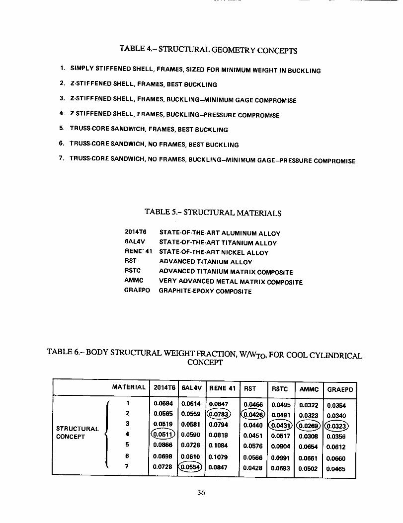
TABLE 4.- STRUCTURAL GEOMETRY CONCEPTS
1. SIMPLY STIFFENED SHELL, FRAMES, SIZED FOR MINIMUM WEIGHT IN BUCKLING
2. Z-STIFFENED SHELL, FRAMES, BEST BUCKLING
3. Z-STIFFENED SHELL, FRAMES, BUCKLING-MINIMUM GAGE COMPROMISE
4. Z-STIFFENED SHELL, FRAMES, BUCKLING-PRESSURE COMPROMISE
5. TRUSS-CORE SANDWICH, FRAMES, BEST BUCKLING
6. TRUSS-CORE SANDWICH, NO FRAMES, BEST BUCKLING
7. TRUSS-CORE SANDWICH, NO FRAMES, BUCKLING-MINIMUM GAGE-PRESSURE COMPROMISE
TABLE 5.- STRUCTURAL MATERIALS
2014T6
6AL4V
RENE' 41
RST
RSTC
AMMC
GRAEPO
STATE-OF-THE-ART ALUMINUM ALLOY
STATE-OF-THE-ART TITANIUM ALLOY
STATE-OF-THE-ART NICKEL ALLOY
ADVANCED TITANIUM ALLOY
ADVANCED TITANIUM MATRIX COMPOSITE
VERY ADVANCED METAL MATRIX COMPOSITE
GRAPHITE-EPOXY COMPOSITE
TABLE 6.- BODY STRUCTURAL WEIGHT FRACTION, W/WTo , FOR COOL CYLINDRICALCONCEPT
STRUCTURAL
CONCEPT
MATERIAL
1
2
3
, 4
5
6
7
2014T6 6AL4V RENE41 RST RSTC
0.05.0.06140.0.7 0.04660.0495
0.0565 0.0559 _ _ 0.0491
o.o_1,oo_, oo,,, oo_,o_oo_,__ioo_ o.o_,, oo,_, 006,,o.o_ oo,_ o,o_, oo_,_o.o,o,0.0699 0.0610 0.1079 0.0566 0.0991
0.0728 _..05_ _') 0.0.7 0.0428 0.0693
AMMC GRAEPO
0.0322 0.0354
0.0323 0.0340
0.0308 0.0356
O.OIk_4 0.0612
0.0661 0.0660
0.0562 0.0465
36
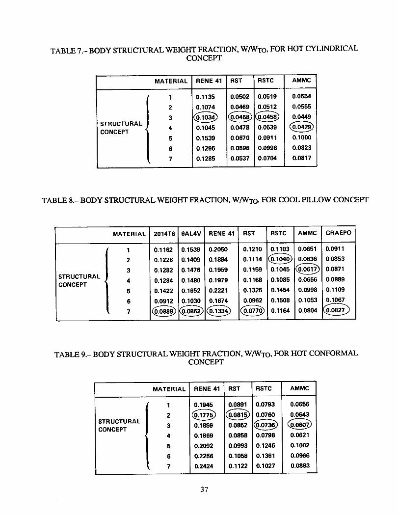
TABLE 7.- BODY STRUCTURAL WEIGHT FRACTION, W/WTo, FOR HOT CYLINDRICALCONCEPT
STRUCTURAL
CONCEPT '
MATERIAL RENE41
1
2
3
4
5
6
7
0.1135
0.1074
0.1045
0.1539
0.1295
0.1285
RST
0.0502
0.0469
0.0478
0.0670
0.0596
0.0537
RSTC AMMC
0.0519 0.0554
0.0512 0.0555
0.0449
0.0539
0.0911 0.1000
0.0996 0,0823
0.0704 0.0817
TABLE 8.- BODY STRUCTURAL WEIGHT FRACTION, W/WTo, FOR COOL PILLOW CONCEPT
STRUCTURAL I
CONCEPT
MATERIAL
1
2
3
4
5
6
7
2014T6 6AL4V RENE 41
0.1162 0.1539
0.1228 0.1409
0.1282 0.1476
0.1284 0.1480
0.1422 0.1652
0.0912 0.1030
0.2050
0.1884
0.1959
0.1979
0.2221
0,1674
RST
0.1210
0.1114
0.1159
0.1168
0.1325
0.0962
RSTC
0.1103
0.1045
0.1085
0.1454
0.1508
0.1154
AMMC
0.0651
0.0636
0.0656
0.0998
0.1053
0.0804
GRAEPO
0.0911
0.0853
0.0871
0.0889
0.1109
0.1067
TABLE 9.- BODY STRUCTURAL WEIGHT FRACTION, W/WT O, FOR HOT CONFORMALCONCEPT
STRUCTURAL
CONCEPT
MATERIAL
1
2
3
4
5
6
, 7
RENE 41
0.1945
0.1859
0.1869
0.2092
0.2256
0.2424
RST
0.0891
0.0852
0.0858
0.0993
0.1058
0.1122
RSTC
0.0793
0.0760
0.0798
0.1246
0.1361
0.1027
AMMC
0.0656
0.0643
0.0621
0.1002
0.0966
0.0883
37
TABLE B 1.- STRUCTURAL GEOMETRY PARAMETERS
STRUCTURALCONCEPT m
2
2
2
2
2
1.667
1.667
0.656
0.911
0.760
0.760
0.605
0.4423
0.3615
Kmg
2.463
2.475
2.039
2.628
4.310
4.820
3.413
Kp
2.463
2.475
1.835
1.576
3.965
3.132
3.413
Kth
0.0
0.0
0.0
0.0
0.459
0.405
0.320
Figure 1.- The all-body configuration.
38
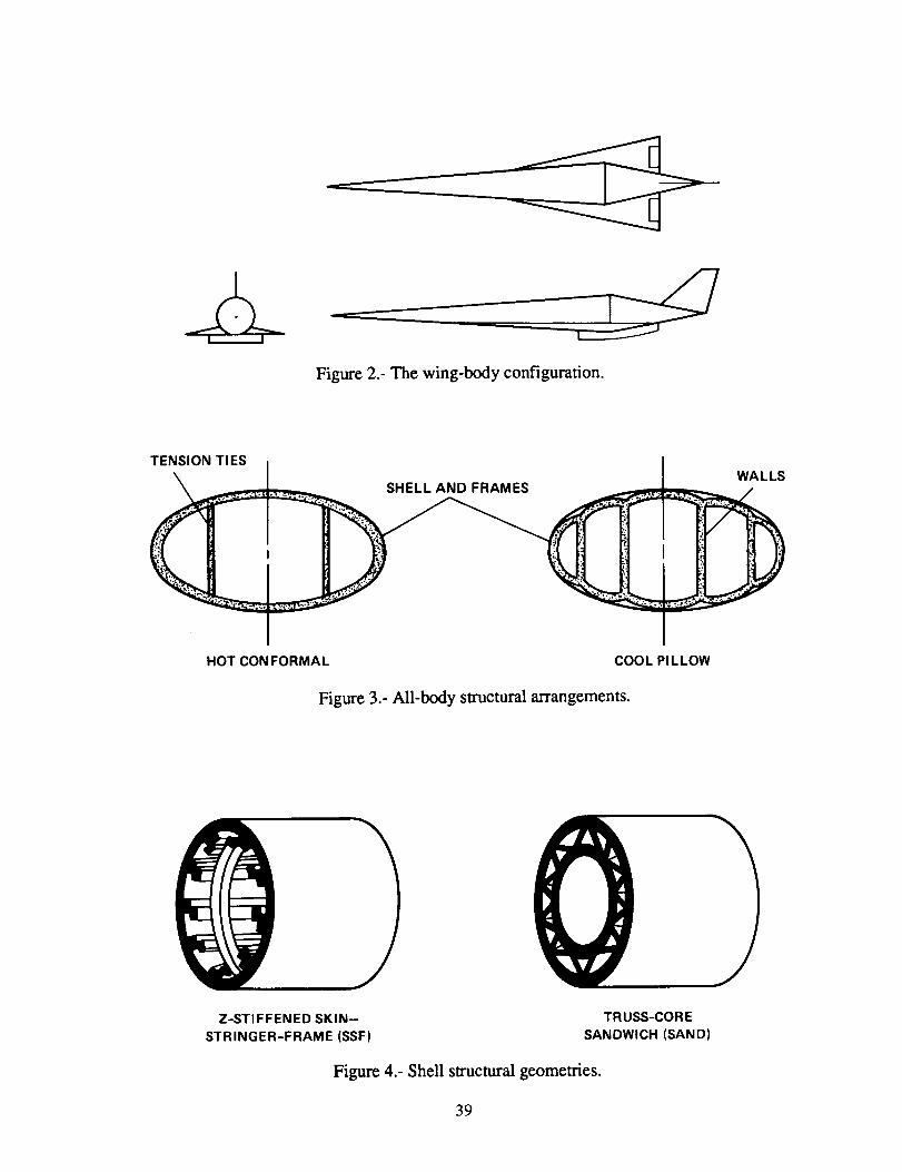
Figure 2.- The wing-body configuration.
TENSION TIES
SHELL AND FRAMES ....
HOTCONFORMAL
,+I
l¢
COOL PI LLOW
Figure 3.- All-body structural arrangements.
WALLS
/
Z-STIFFENED SKIN--
STRINGER-FRAME (SSF)
TRUSS-CORE
SANDWICH (SAND)
Figure 4.- Shell structural geometries.
39

4
3
_-04::
%z
11-
_ ALL BODY
/
0 25 50 75 100 125I
150
BODY STATION, ft
Figure 5.- Bending-moment distribution.
I
175
.O9
.08
.07
o_.o6
.05
.O4
fm
m
It.
COOL
CYLINDRICAL
m "It' 'It"
== =.
M,I
n-
HOT COOL HOT
CYLINDRICAL PILLOW CONFORMAL
m
,1(.m
m
u. u_
I- I-- I--ca ¢n cn =E
m
,I(-
m
C] u.z_¢¢ ¢J
n- <:
i
m
LL
!"ca =Em
i
I
Figure 6.- A comparision of concepts.
4O

.10
.O9
.O8
.07
.06
oI-
.05
.04
.03
.02
.01
6AL4V/SAND/ II RST/SAND
L; ./"
AMMC/SAN /7 _ 6AL4V/SSF
RST/SSF
/.................. I" /
-.=-.7-,-:_.0.._/ /_-.-=_..-=._,,,/
GRAEPO/SSF / .."/.... .J--4..--,_...._
. / _.,,,
...... I/ AMMC/SSF
(a)I I I I
0 10 20 30 40
Pg, psi
Figure 7.- The effect of gage pressure.
.10
.O9
.O8
.O7
.O6
o
.05
.04
.O3
.O2
.01
RSTC/SAND // / AMMC/SSF
,Y
.s,,s,_o/ i /t/ -_RST/SSF
/.__.,_ RSTC/SSF
I
(b)I I I I
10 20 30 40
Pg, psi
(a) Cool cylindrical concept; (b) hot cylindrical concept.
41

Ot--
.10
.O9
.08
.07
.O6
.O5
.04
.03i
.02
.01
00
• / / ,,// GRAEPO/SSF
eA,4v/sAND//.// /
..... •_ .. " ,/,,,_
AMMC/SAND ,/ AMMC/SSF/
/
o J
(c)
RSTC/SAND AMMC/SAND
H r '.lo ...l I /I
I
.o, t iX#.08 / ,_J,",,s',"C,=F
.07 _AMMC/SSF
#/
.06 ,,,_t/
I
.04
.03
.02
.01
OI--
.05
(d)i I I I 0 I I I I
10 20 30 40 0 10 20 30 40
Pg, psi Pg, psi
Figure 7.- Concluded. (c) Cool pillow concept; (d) hot conformal concept.
42

.04
(a)
o.oi
%g,i,. .o2
Figure 8,. The effect of minimum gage.
•O3 (b)o
.ol
(a)CoolcYl/nd,.-/ca]COncept; %g.a,. ,02
(b) hot Cylindrical COncept
.03
43
6AL4V/SAND
AMMC/SAND
/ // / //"
AMMC/SSF
Figure 8.- Concluded.
•vo[ SsTc/s_o _.t.09 ....--_.k--....._"
•o6__"_ _ - I "-'-'" _
.o iL.-"
_.0405/ AMMC/S,_F
"03f!
.0
0I
.01
tmg, in.
(c) Cool pillow COncept; (d) hot conformal COncept.
L._.02
.03
44
.10
.O9
.O8
.07
.O6
oI..-.
.05
.O4
.O3
.O2
.01
"_ / 6AL4V/SAND
\\x t,_ ""_ AMMC/SAND
,_,_.k? _ -'"'_,..---- _ 6AL'V/SSF._'_._ ....... "_.... ,, GRAEPO/SAND
_'--_:" "_"=_-:----'-...... _-_ RST/SAND
_'$_ GRAEPO/SSF "_.-_ RST/SSF
- ____ __ ...____.:
.10
.09
.O8
.O7
.06
O
.05
RSTC/SAND
V
\.°%
_...._
\_'._ ........ __,_.._
-:'. ...... - ..... -e,--
RSTC/SSFRST/SSF
.04
.03
.02
.01
(a) 0 (b)I I I I I , I I I I J
0 200 400 600 800 1000 0 200 400 600 800 1000
WTO , KIb WTO, KIb
Figure 9.- The effect of gross take-off weight. (a) Cool cylindrical concept; (b) hot cylindrical concept.
45

OI--
.10
.09
,08
.07
,06
.05_
.04
.03
.02
.01
0
| GRAEPO/SSF //6AL4V/SAND
•"_,_."
"* :,,_r."_ ._" GRAEPO/SAND
AMMC/SSF
(c)
0
.10
.09
.08
.07
.06
0I"
.o5
.O4
.03
.O2
.01
AMMC/SAND /
•_ / RSTC/7:..-""
,,J SJ AMMC/SSF
(d)i i i i ! 0 l i i I I
200 400 600 800 1000 0 200 400 600 800 1000
WTo, KIb. WTO ,KIb
Figure 9.- Concluded. (c) Cool pillow concept; (d) hot conformal concept.
46
.10
.09
.08
.07
.O6
.05
6AL4V/SAND AMMC/SAND / !
V /.4... ........"" / /
6AL4V/SSF J'"" """'" ,, / i
.. / /.h'"...l ..... S // RST/SAND /
....../ _____I- .L...j /-7"-'_ ..... - ..._ _'" _"_
o.,_o_s_.o=--__ .:,_7- ./GRAEPO/SSF •
.... _L....--_ "''I ...-"_I-- .............. AMMC/SSF
.04
.03
.02
.01
(a)0
-500| I I I I
0 500 1000 1500 2000T, °F
Figure 10.- The effect of structural temperature. (a) Hot and cool cylindrical concepts.
47

•10 r 6AL4V/SAND / .
/ ./ ,,,c,s,,o/ /.o91-G.AE.O/SSF..-f" / /"
/ \ ..._:_ / GRAEPO/SAND / / ./
')'I 7 ...... /
$RST/SAND /
.07 J
.06
O
.05
.04
.03
.02
.01
(b)0-500
jS
4, o
p_............. -7 oAMMC/SSF
| I I I |
0 500 1000 1500 2000T°F
Figure 10.- Continued. (b) Cool pillow concept.
48

OI,-.
F.
.10
.09
.06
.O5
.04
.O3
.O2
.01
TRSTC/SAND
.ram,,. • • _
RSTC_SSF
//
//
AMMC/SSF s S
SS
(c)I i l I
0 50O
Figure 10.- Concluded.
1000 1500T,°F
(c) Hot conformal concept.
2000
49
,08"
.O6
Ok-
F.04
.02
0
t_ M.
<: _J
n- n- _ uJ
; i cc
; _ in
I
r//i.,
#'/y//j
i
COOL
CYLINDRICAL
IL
IE IE
IL
C.IIEIE
"////,¢/11_
i//lJ_.///J
NN
PTA
m
F-1HOT COOL HOT
CYLINDRICAL PILLOW CONFORMAL
WING
VOLUME
PENALTY
TAN K
NONOPTIMUM
SPANWlSE
BEAM
TENSION
TIES
FRAMES
WALLS
SHELL
Figure 11.- Body structural weight breakdown.
5O
1.00
.75
¢n- .50t_
.25
0
MIN. GAGE
(a)I
25
BUCKL, O M'N.IGAGE/
I I I I I I
50 75 100 125 150 175
BODY STATION, ft
1.00
.75
%-_ .50
.25
(b)
MIN. GAGE
BUCKLING PRESSURE
MIN. __GAGE
I I I | I I !
0 25 50 75 100 125 150 175
BODY STATION, ft
Figure 12.- Shell weight per unit surface area. (a) Cool cylindrical concept, RST/SSF; (b) cool cylindrical
concept, RST/SAND.
51
1.00
.75
.25 I(c)
MIN. GAGE
0
-I
I I i I I I l
25 50 75 100 125 150 175
BODY STATION, ft
1.00
.75
%J_
g ,50¢,_
.25
(d)
MIN. GAGE |MIN.|v _ PRESSURE ---_I_-GAGE--_
I I I I I I I
0 25 50 75 100 125 150 175
BODY STATION, ft
Figure 12.- Continued. (c) Cool cylindrical concept, RSTC/SSF; (d) cool cylindrical concept,AMMC/SSF.
52
1.00
.75
044_-= .50
.25
0
(e)
MIN. GAGE
I I I I i I I
25 50 75 100 125 150 175
BODY STATION, ft
1.00
.75
%"=.50
.25
_-- MIN. GAGE _--I_- PRESSURE I_1_ _-1
. MIN.
GAGE
0 25 50I I I I I
75 100 125 150 175
BODY STATION, ft
Figure 12.- Continued. (e) Cool cylindrical concept, GRAEPO/SSF; (f) hot cylindrical concept,AMMC/SSF.
53

1.00
.75 "
%.,0-- .50
.25
(g)
1.00
.75
%.50
_C
.25
MIN. GAGE I I MIN. GAGE
BUCKLING
i I I i I i I
25 50 75 100 125 150 175
BODY STATION, ft
_l_ ,RE=oRE---_-_ _-- M,,.GAGEMIN. GAGE r
BUCKLING
(h)
Figure 12.- Concluded.
I I I l I I I
25 50 75 100 125 150 175
BODY STATION, ft
(g) Cool pillow concept, AMMC/SSF; (h) hot conformal concept, AMMC/SSF.
54

o_plY=_
,\f
_- x
o_P2Y='E
D
=1: _2 "---'-D
Figure A 1.- The wing-body geometry.
,2!Mt | P
A
b
ds lr
ALL-BODY
Figure A2.- The all-body geometry.
P y
55
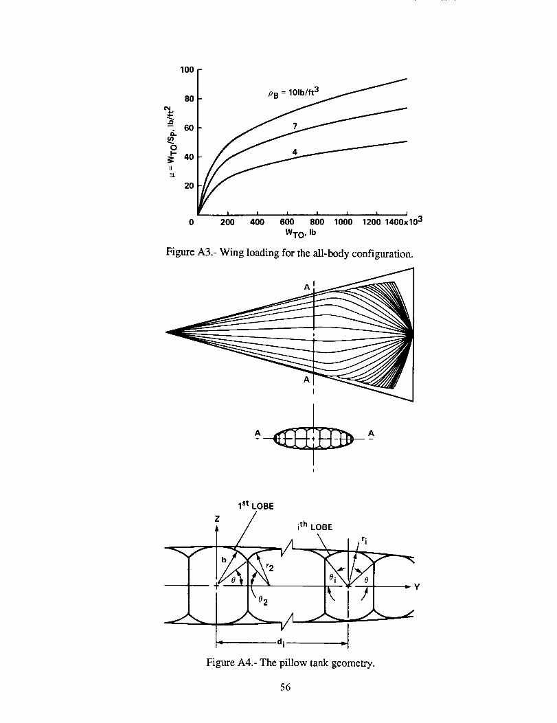
100
80
r_ 60
,.__:_ 40II
:::L
20
0
PB = 101_
7
I I I I I I I
200 400 600 800 1000 1200 1400x103
WTO, Ib
Figure A3.- Wing loading for the all-body configuration.
A
A
I
J_.L
I st LOBE
Z / ith LOBE
-- d i =!
Figure A4.- The pillow tank geometry.
-._y
56

-.t I.-03_.
yl' _ t ,-
ts I_b S _-
Figure B 1.- The Z-stiffened shell geometry.
__- bf "----_1
Figure B2.- The truss-core sandwich geometry.
Figure B3.-
5
3
2
TRUSS-CORE/
/ /_z_o/" _ INTEGRALLY STIFFEND
i I SHELL t J
2 3 4 5 6
a/b
A comparision of weights of unpressurized elliptic and circular shells.
57

1058
6
i 2
104>. 8
,_ 6
4
EXISTING
AIRCRAFT
ADVANCEDTECHNOLOGY
HYPERSONIC
AIRCRAFT
103
105 2 4 6 8 106 2 4 6 8 107
x~(WToLf).3 Q.1775 1.9 (4r) 1.05
Figure B4.- Correlations and comparisons of body weight.
1.2
t_ .8
8 8.,
0 J i t ;1 2 3 4 5
a/b
Figure C1.- A comparision of spring constants of elliptic and circular frames.
58
Report Documentation Page
1. Report No.
NASA TM 101028
2. Government Accession No.
4. Title and Subtitle
Bodyweight of Hypersonic Aircraft: Part i
7. Authorls)
Mark D. Ardema
9. Performing Organization Name and Address
Ames Research Center
Moffett Field, CA 94035
12. Spon_ring Agency Name and Addre_
National Aeronautics and Space Administration
Washington, DC 20546
3. Recipient's Catalog No.
5. Report Date
October 1988
6. Performing Organization Code
8. Performing Organization Report No.
A 88279
10. Work Unit No.
763-01-61
11. Contract or Grant No.
13. Type of Repo_ and Period Covered
Technical Memorandum
14. Sponsoring Agency Code
15. Supplementaw Not_
Point of Contact: Mark D. Ardema, Ames Research Center, M/S 237-11
Moffett Field, CA 94035 (415) 694-6578 or FTS 464-6578
16. Abstract
The load-bearing body weight of wing-body and all-body hypersonic air-
craft is estimated for a wide variety of structural materials and geometries.
Variations of weight with key design and configuration parameters are pre-
sented and discussed. Both hot and cool structure approaches are considered
in isotropic, organic composite, and metal matrix composite materials;
structural shells are sandwich or skin-stringer. Conformal and pillow-tank
designs are investigated for the all-body shape. The results identify the
most promising hypersonic aircraft body-structure-design approaches and their
weight trends. Geometric definition of vehicle shapes and structural analy-
sis methods are presented in appendices.
17, Key Words (Suggested by Author(s))
Hypersonic aircraft
Structural weight
Aircraft design
19. Security Classif, (of this repot)
Unclassified
NASA FORM 1626 OCT 86
18. Distribution Stateme_
Unclassified-_
Gc:4o bey tqqo
Subject Category - 05
20, Security Classif. (of this page)
Unclassified
21. No. of pages
62
22. Price
A05

Related Documents