SEC-1 BODY EXTERIOR, DOORS, ROOF & VEHICLE SECURITY C D E F G H I J L M SECTION SEC A B SEC N O P CONTENTS SECURITY CONTROL SYSTEM WITH INTELLIGENT KEY SYSTEM BASIC INSPECTION ................................... 5 DIAGNOSIS AND REPAIR WORKFLOW ......... 5 Work Flow ................................................................ 5 INSPECTION AND ADJUSTMENT .................... 8 ADDITIONAL SERVICE WHEN REPLACING CONTROL UNIT ......................................................... 8 ADDITIONAL SERVICE WHEN REPLACING CONTROL UNIT : Special Repair Requirement ...... 8 ECM RE-COMMUNICATING FUNCTION .................. 8 ECM RE-COMMUNICATING FUNCTION : De- scription .................................................................... 8 ECM RE-COMMUNICATING FUNCTION : Spe- cial Repair Requirement ........................................... 8 FUNCTION DIAGNOSIS .............................. 9 INTELLIGENT KEY SYSTEM/ENGINE START FUNCTION ............................................ 9 System Diagram ....................................................... 9 System Description .................................................. 9 Component Parts Location ..................................... 11 Component Description .......................................... 12 NVIS (NISSAN VEHICLE IMMOBILIZER SYS- TEM-NATS) .......................................................13 System Diagram ..................................................... 13 System Description ................................................ 13 Component Parts Location ..................................... 15 Component Description ......................................... 15 VEHICLE SECURITY SYSTEM ........................17 System Diagram ..................................................... 17 System Description ................................................ 17 Component Parts Location ..................................... 18 Component Description .......................................... 19 DIAGNOSIS SYSTEM (BCM) ...........................20 COMMON ITEM ........................................................20 COMMON ITEM : CONSULT-III Function (BCM - COMMON ITEM) ....................................................20 IMMU .........................................................................20 IMMU : CONSULT-III Function (BCM - IMMU) .......20 THEFT ALM ..............................................................21 THEFT ALM : CONSULT-III Function (BCM - THEFT ALM) ..........................................................21 DIAGNOSIS SYSTEM (INTELLIGENT KEY UNIT) ................................................................. 23 CONSULT-III Function (INTELLIGENT KEY) .........23 COMPONENT DIAGNOSIS ........................ 26 U1000 CAN COMM CIRCUIT ........................... 26 Description ..............................................................26 DTC Logic ...............................................................26 Diagnosis Procedure ..............................................26 U1010 CONTROL UNIT (CAN) ......................... 27 Description ..............................................................27 DTC Logic ...............................................................27 Diagnosis Procedure ..............................................27 Special Repair Requirement ...................................27 B2013 ID DISCORD I-KEY-STRG .................... 28 Description ..............................................................28 DTC Logic ...............................................................28 Diagnosis Procedure ..............................................28 B2190, P1614 NATS ANTENNA AMP. ............ 31 Description ..............................................................31 DTC Logic ...............................................................31 Diagnosis Procedure ..............................................31 B2191, P1615 DIFFERENCE OF KEY ............. 34 Description ..............................................................34 DTC Logic ...............................................................34 Diagnosis Procedure ..............................................34

Welcome message from author
This document is posted to help you gain knowledge. Please leave a comment to let me know what you think about it! Share it to your friends and learn new things together.
Transcript

BODY EXTERIOR, DOORS, ROOF & VEHICLE SECURITY
C
D
E
SECTION SEC A
B
SECURITY CONTROL SYSTEM
F
G
H
I
J
L
M
EC
N
O
P
CONTENTS
S
WITH INTELLIGENT KEY SYSTEM
BASIC INSPECTION .................................... 5
DIAGNOSIS AND REPAIR WORKFLOW .......... 5Work Flow .................................................................5
INSPECTION AND ADJUSTMENT ..................... 8
ADDITIONAL SERVICE WHEN REPLACING CONTROL UNIT ..........................................................8
ADDITIONAL SERVICE WHEN REPLACING CONTROL UNIT : Special Repair Requirement .......8
ECM RE-COMMUNICATING FUNCTION ...................8ECM RE-COMMUNICATING FUNCTION : De-scription .....................................................................8ECM RE-COMMUNICATING FUNCTION : Spe-cial Repair Requirement ............................................8
FUNCTION DIAGNOSIS ............................... 9
INTELLIGENT KEY SYSTEM/ENGINE START FUNCTION ............................................. 9
System Diagram ........................................................9System Description ...................................................9Component Parts Location ......................................11Component Description ...........................................12
NVIS (NISSAN VEHICLE IMMOBILIZER SYS-TEM-NATS) ........................................................13
System Diagram ......................................................13System Description .................................................13Component Parts Location ......................................15Component Description ..........................................15
VEHICLE SECURITY SYSTEM .........................17System Diagram ......................................................17System Description .................................................17Component Parts Location ......................................18Component Description ...........................................19
DIAGNOSIS SYSTEM (BCM) ............................20
COMMON ITEM .........................................................20COMMON ITEM : CONSULT-III Function (BCM - COMMON ITEM) .....................................................20
IMMU ..........................................................................20IMMU : CONSULT-III Function (BCM - IMMU) ........20
THEFT ALM ...............................................................21THEFT ALM : CONSULT-III Function (BCM - THEFT ALM) ...........................................................21
DIAGNOSIS SYSTEM (INTELLIGENT KEY UNIT) .................................................................23
CONSULT-III Function (INTELLIGENT KEY) ..........23
COMPONENT DIAGNOSIS .........................26
U1000 CAN COMM CIRCUIT ...........................26Description ...............................................................26DTC Logic ................................................................26Diagnosis Procedure ...............................................26
U1010 CONTROL UNIT (CAN) .........................27Description ...............................................................27DTC Logic ................................................................27Diagnosis Procedure ...............................................27Special Repair Requirement ....................................27
B2013 ID DISCORD I-KEY-STRG ....................28Description ...............................................................28DTC Logic ................................................................28Diagnosis Procedure ...............................................28
B2190, P1614 NATS ANTENNA AMP. ............31Description ...............................................................31DTC Logic ................................................................31Diagnosis Procedure ...............................................31
B2191, P1615 DIFFERENCE OF KEY .............34Description ...............................................................34DTC Logic ................................................................34Diagnosis Procedure ...............................................34
SEC-1

B2192, P1611 ID DISCORD, IMMU-ECM ......... 35Description .............................................................. 35DTC Logic ............................................................... 35Diagnosis Procedure .............................................. 35
B2193, P1612 CHAIN OF ECM-IMMU .............. 37Description .............................................................. 37DTC Logic ............................................................... 37Diagnosis Procedure .............................................. 37
B2194 ID DISCORD IMMU-I-KEY ..................... 38Description .............................................................. 38DTC Logic ............................................................... 38Diagnosis Procedure .............................................. 38
B2552 INTELLIGENT KEY ................................ 39Description .............................................................. 39DTC Logic ............................................................... 39Diagnosis Procedure .............................................. 39Special Repair Requirement ................................... 39
B2590 ID DISCORD BCM-I-KEY ....................... 40Description .............................................................. 40DTC Logic ............................................................... 40Diagnosis Procedure .............................................. 40
P1610 LOCK MODE .......................................... 41Description .............................................................. 41DTC Logic ............................................................... 41Diagnosis Procedure .............................................. 41
POWER SUPPLY AND GROUND CIRCUIT ..... 42
INTELLIGENT KEY UNIT ......................................... 42INTELLIGENT KEY UNIT : Diagnosis Procedure ... 42
BCM ........................................................................... 42BCM : Diagnosis Procedure ................................... 42
KEY CYLINDER SWITCH ................................. 43Description .............................................................. 43Component Function Check ................................... 43Diagnosis Procedure .............................................. 43
GLASS HATCH AJAR SWITCH ....................... 45Diagnosis Procedure .............................................. 45
IGNITION KNOB SWITCH ................................. 46Ignition Knob Switch Check .................................... 46
HORN FUNCTION ............................................. 48Symptom Table ...................................................... 48
VEHICLE SECURITY INDICATOR .................... 49Description .............................................................. 49Component Function Check ................................. 49Diagnosis Procedure .............................................. 49
ECU DIAGNOSIS ........................................ 51
BCM (BODY CONTROL MODULE) .................. 51Reference Value ..................................................... 51
Wiring Diagram - VEHICLE SECURITY SYSTEM ... 52Wiring Diagram - NVIS ............................................ 62Fail Safe ................................................................. 71DTC Inspection Priority Chart ............................... 71DTC Index .............................................................. 71
INTELLIGENT KEY UNIT .................................. 72Reference Value ..................................................... 72Wiring Diagram - INTELLIGENT KEY SYSTEM/ENGINE START FUNCTION - ................................ 73Fail Safe ................................................................. 87DTC Inspection Priority Chart ............................... 87DTC Index .............................................................. 87
IPDM E/R (INTELLIGENT POWER DISTRI-BUTION MODULE ENGINE ROOM) ................. 88
Reference Value ..................................................... 88Fail Safe ................................................................. 88DTC Index .............................................................. 88
SYMPTOM DIAGNOSIS ............................ 89
INTELLIGENT KEY SYSTEM/ENGINE START FUNCTION SYMPTOMS ...................... 89
Symptom Table ....................................................... 89
VEHICLE SECURITY SYSTEM SYMPTOMS ... 90Symptom Table ....................................................... 90
NISSAN VEHICLE IMMOBILIZER SYSTEM-NATS SYMPTOMS ............................................ 91
Symptom Table ....................................................... 91
ON-VEHICLE MAINTENANCE .................. 92
PRE-INSPECTION FOR DIAGNOSTIC ............ 92Basic Inspection ...................................................... 92Vehicle Security Operation Check .......................... 92
ON-VEHICLE REPAIR ............................... 94
INTELLIGENT KEY UNIT .................................. 94Removal and Installation ......................................... 94
REMOVAL AND INSTALLATION .............. 95
NATS ANTENNA AMP. ..................................... 95Removal and Installation ......................................... 95
INTELLIGENT KEY UNIT .................................. 96Removal and Installation ......................................... 96
REMOTE KEYLESS ENTRY RECEIVER ......... 97Removal .................................................................. 97Installation ............................................................... 97WITHOUT INTELLIGENT KEY SYSTEM
BASIC INSPECTION .................................. 98
DIAGNOSIS AND REPAIR WORKFLOW ......... 98Work Flow ............................................................... 98
SEC-2

C
D
E
F
G
H
I
J
L
M
A
B
EC
N
O
P
S
INSPECTION AND ADJUSTMENT .................. 101
ADDITIONAL SERVICE WHEN REPLACING CONTROL UNIT ...................................................... 101
ADDITIONAL SERVICE WHEN REPLACING CONTROL UNIT : Special Repair Requirement ... 101
ECM RE-COMMUNICATING FUNCTION ............... 101ECM RE-COMMUNICATING FUNCTION : De-scription ................................................................. 101ECM RE-COMMUNICATING FUNCTION : Spe-cial Repair Requirement ........................................ 101
FUNCTION DIAGNOSIS ............................ 102
NVIS (NISSAN VEHICLE IMMOBILIZER SYS-TEM-NATS) ...................................................... 102
System Diagram .................................................... 102System Description ............................................... 102Component Parts Location .................................... 103Component Description ........................................ 104
VEHICLE SECURITY SYSTEM ....................... 105System Diagram .................................................... 105System Description ............................................... 105Component Parts Location .................................... 106Component Description ......................................... 107
DIAGNOSIS SYSTEM (BCM) .......................... 108
COMMON ITEM ....................................................... 108COMMON ITEM : CONSULT-III Function (BCM - COMMON ITEM) ................................................... 108
IMMU ........................................................................ 108IMMU : CONSULT-III Function (BCM - IMMU) ..... 108
THEFT ALM ............................................................. 109THEFT ALM : CONSULT-III Function (BCM - THEFT ALM) ......................................................... 109
COMPONENT DIAGNOSIS ....................... 110
U1000 CAN COMM CIRCUIT ........................... 110Description ............................................................ 110DTC Logic ............................................................. 110Diagnosis Procedure ............................................. 110
U1010 CONTROL UNIT (CAN) ........................ 111Description ............................................................ 111DTC Logic ............................................................. 111Diagnosis Procedure ............................................. 111Special Repair Requirement ................................. 111
B2190, P1614 NATS ANTENNA AMP. ............ 112Description ............................................................ 112DTC Logic ............................................................. 112Diagnosis Procedure ............................................. 112
B2191, P1615 DIFFERENCE OF KEY ............. 115Description ............................................................ 115DTC Logic ............................................................. 115
Diagnosis Procedure .............................................115
B2192, P1611 ID DISCORD, IMMU-ECM ....... 116Description .............................................................116DTC Logic ..............................................................116Diagnosis Procedure .............................................116
B2193, P1612 CHAIN OF ECM-IMMU ............ 118Description .............................................................118DTC Logic ..............................................................118Diagnosis Procedure .............................................118
P1610 LOCK MODE ....................................... 119Description .............................................................119DTC Logic ..............................................................119Diagnosis Procedure .............................................119
POWER SUPPLY AND GROUND CIRCUIT .. 120
BCM .........................................................................120BCM : Diagnosis Procedure ..................................120
KEY CYLINDER SWITCH ............................... 121Description .............................................................121Component Function Check ..................................121Diagnosis Procedure .............................................121
GLASS HATCH AJAR SWITCH ..................... 123Diagnosis Procedure .............................................123
HORN FUNCTION ........................................... 124Symptom Table .....................................................124
VEHICLE SECURITY INDICATOR ................. 125Description .............................................................125Component Function Check ................................125Diagnosis Procedure .............................................125
ECU DIAGNOSIS ....................................... 127
BCM (BODY CONTROL MODULE) ............... 127Reference Value ....................................................127Wiring Diagram - VEHICLE SECURITY SYSTEM ..128Wiring Diagram - NVIS - ........................................138DTC Inspection Priority Chart .............................145DTC Index .............................................................145
IPDM E/R (INTELLIGENT POWER DISTRI-BUTION MODULE ENGINE ROOM) .............. 146
Reference Value ....................................................146Fail Safe ................................................................146DTC Index .............................................................146
SYMPTOM DIAGNOSIS ............................ 147
VEHICLE SECURITY SYSTEM SYMPTOMS . 147Symptom Table .....................................................147
NISSAN VEHICLE IMMOBILIZER SYSTEM-NATS SYMPTOMS ......................................... 148
Symptom Table .....................................................148
SEC-3

ON-VEHICLE MAINTENANCE ..................149
PRE-INSPECTION FOR DIAGNOSTIC ........... 149Basic Inspection ....................................................149
ON-VEHICLE REPAIR ...............................150
VEHICLE SECURITY SYSTEM ....................... 150Removal and Installation .......................................150
REMOVAL AND INSTALLATION .............151
NATS ANTENNA AMP. ....................................151Removal and Installation ....................................... 151
REMOTE KEYLESS ENTRY RECEIVER ........152Removal ................................................................ 152Installation ............................................................. 152
SEC-4

DIAGNOSIS AND REPAIR WORKFLOW[WITH INTELLIGENT KEY SYSTEM]
C
D
E
F
G
H
I
J
L
M
A
B
EC
N
O
P
< BASIC INSPECTION >
S
BASIC INSPECTIONDIAGNOSIS AND REPAIR WORKFLOWWork Flow INFOID:0000000001689505
OVERALL SEQUENCE
DETAILED FLOWALKIA0538GB
SEC-5

[WITH INTELLIGENT KEY SYSTEM]DIAGNOSIS AND REPAIR WORKFLOW
< BASIC INSPECTION >
1.GET INFORMATION FOR SYMPTOM
Get the detailed information from the customer about the symptom (the condition and the environment whenthe incident/malfunction occurred).
>> GO TO 2.2.CHECK DTC
1. Check DTC for Intelligent Key unit and BCM.2. Perform the following procedure if DTC is displayed.- Erase DTC.- Study the relationship between the cause detected by DTC and the symptom described by the customer.3. Check related service bulletins for information.Is any symptom described and any DTC detected?Symptom is described, DTC is displayed>>GO TO 3.Symptom is described, DTC is not displayed>>GO TO 4.Symptom is not described, DTC is displayed>>GO TO 5.
3.CONFIRM THE SYMPTOM
Confirm the symptom described by the customer.Connect CONSULT-III to the vehicle in “DATA MONITOR” mode and check real-time diagnosis results.Verify relation between the symptom and the condition when the symptom is detected.
>> GO TO 5.4.CONFIRM THE SYMPTOM
Confirm the symptom described by the customer.Connect CONSULT-III to the vehicle in “DATA MONITOR ” mode and check real-time diagnosis results.Verify relation between the symptom and the condition when the symptom is detected.
>> GO TO 6.5.PERFORM DTC CONFIRMATION PROCEDURE
Perform DTC Confirmation Procedure for the displayed DTC, and then check that DTC is detected again.If two or more DTCs are detected, refer to SEC-71, "DTC Inspection Priority Chart" (Intelligent Key unit),SEC-71, "DTC Inspection Priority Chart" (BCM) and determine trouble diagnosis order.Is DTC detected?YES >> GO TO 8.NO >> Refer to GI-51, "Intermittent Incident".
6.PERFORM BASIC INSPECTION
Perform Basic Inspection. Refer to SEC-5, "Work Flow".
>> GO TO 7.7.DETECT MALFUNCTIONING SYSTEM BY SYMPTOM TABLE
Detect malfunctioning system according to Symptom Table based on the confirmed symptom in step 4.
>> GO TO 8.8.DETECT MALFUNCTIONING PART BY DIAGNOSTIC PROCEDURE
Inspect according to Diagnostic Procedure of the system.NOTE:The Diagnostic Procedure is described based on open circuit inspection. A short circuit inspection is alsorequired for the circuit check in the Diagnostic Procedure.
>> GO TO 9.
SEC-6

DIAGNOSIS AND REPAIR WORKFLOW[WITH INTELLIGENT KEY SYSTEM]
C
D
E
F
G
H
I
J
L
M
A
B
EC
N
O
P
< BASIC INSPECTION >
S
9.REPAIR OR REPLACE THE MALFUNCTIONING PART
1. Repair or replace the malfunctioning part.2. Reconnect parts or connectors disconnected during Diagnostic Procedure again after repair and replace-
ment.3. Check DTC. If DTC is displayed, erase it.
>> GO TO 10.10.FINAL CHECK
When DTC was detected in step 9, perform DTC Confirmation Procedure or Component Function Checkagain, and then check that the malfunctions have been fully repaired.When symptom was described by the customer, refer to the confirmed symptom in step 3 or 4, and check thatthe symptom is not detected.Does the symptom reappear?YES (DTC is detected)>>GO TO 8.YES (Symptom remains)>>GO TO 6.NO >> INSPECTION END
SEC-7

[WITH INTELLIGENT KEY SYSTEM]INSPECTION AND ADJUSTMENT
< BASIC INSPECTION >INSPECTION AND ADJUSTMENTADDITIONAL SERVICE WHEN REPLACING CONTROL UNITADDITIONAL SERVICE WHEN REPLACING CONTROL UNIT : Special Repair Re-quirement INFOID:0000000001689506
Refer to the CONSULT-III Operation Manual-NATS.ECM RE-COMMUNICATING FUNCTIONECM RE-COMMUNICATING FUNCTION : Description INFOID:0000000001689507
Performing following procedure can automatically perform re-communication of ECM and BCM, but only whenthe ECM has been replaced with a new one (*1).*1: New one means an ECM which has never been energized on-board.(In this step, initialization procedure by CONSULT-III is not necessary)NOTE:• When registering new Key IDs or replacing the ECM that is not brand new, refer to CONSULT-III Oper-
ation Manual NATS.• If multiple keys are attached to the key holder, separate them before work.• Distinguish keys with unregistered key ID from those with registered ID.
ECM RE-COMMUNICATING FUNCTION : Special Repair Requirement INFOID:0000000001689508
1.PERFORM ECM RE-COMMUNICATING FUNCTION
1. Install ECM.2. Using a registered key (*2), turn ignition switch to “ON”.
*2: To perform this step, use the key that has been used before performing ECM replacement.3. Maintain ignition switch in “ON” position for at least 5 seconds.4. Turn ignition switch to “OFF”.5. Start engine.Can engine be started?YES >> Procedure is completed.NO >> Initialize control unit. Refer to CONSULT-III Operation Manual NATS.
SEC-8

INTELLIGENT KEY SYSTEM/ENGINE START FUNCTION[WITH INTELLIGENT KEY SYSTEM]
C
D
E
F
G
H
I
J
L
M
A
B
EC
N
O
P
< FUNCTION DIAGNOSIS >
S
FUNCTION DIAGNOSISINTELLIGENT KEY SYSTEM/ENGINE START FUNCTIONSystem Diagram INFOID:0000000001689509
System Description INFOID:0000000001689510
INPUT/OUTPUT SIGNAL CHARTIntelligent Key Unit
IPDM E/R
BCM
SYSTEM DESCRIPTION • The engine start function of Intelligent Key system is a system that makes it possible to start and stop the
engine without using the key. It verifies the electronic ID using two-way communications when pressing theignition knob switch while carrying the Intelligent Key, which operates based on the results of electronic IDverification for Intelligent Key using two-way communications between the Intelligent Key and the vehicle.NOTE:The driver should carry the Intelligent Key at all times.
Switch/Input signal Input signal toIntelligent Key unit
Intelligent Key unit function Actuator/Output signal
Key switch Mechanical key (insert/remove)
Engine start function
• KEY warning lamp/buzzer• Steering lock unit• Starter relay request (to IPDM E/R)• Inside key antenna
(Instrument panel, center console, luggage compartment)
• Key interlock solenoid
Ignition knob switch Ignition knob(push/release)
Steering lock unit Steering lock (lock/unlock)
Inside key antenna(Front and rear center console, over-head console, luggage compartment)
Intelligent key(inside antenna detection area or not.)
Switch/Input signal Input signal toIPDM E/R IPDM E/R function Actuator/Output signal
Park/neutral position switch P, N range Engine start function • Starter relay• Starter motor
Switch/Input signal Input signal toBCM BCM function Actuator/Output signal
Key switch Brake (press/release) Engine start function
• Inside key antenna(Instrument panel, center console, luggage compartment)
ALKIA1267GB
SEC-9

[WITH INTELLIGENT KEY SYSTEM]INTELLIGENT KEY SYSTEM/ENGINE START FUNCTION
< FUNCTION DIAGNOSIS >• Intelligent Key has 2 IDs (for Intelligent Key and for NATS). It can perform the door lock/unlock operation and
the engine start operation when the registered Intelligent Key is carried.• When the Intelligent Key battery is discharged, it can be used as emergency back-up by inserting the
mechanical key set in the Intelligent Key to the ignition key cylinder. At that time, perform the NATS ID verifi-cation. If it is used when the Intelligent Key is carried, perform the Intelligent Key ID verification.
• If the ID is successfully verified, and when the ignition knob switch is pressed, steering lock will be releasedand initiating the engine will be possible.
• The door lock/unlock operation can be performed when the Intelligent Key battery is discharged, by operat-ing the driver door key cylinder using the mechanical key set in the Intelligent Key.
• Up to 4 Intelligent Keys can be registered (including the standard Intelligent Key) on request from the owner.NOTE:• Refer to SEC-20, "COMMON ITEM : CONSULT-III Function (BCM - COMMON ITEM)" for any functions
other than engine start function of Intelligent Key system.
PRECAUTIONS FOR INTELLIGENT KEY SYSTEM• For vehicles equipped with the Intelligent Key system, the transponder [the chip for NATS ID verifi-
cation] is integrated into the Intelligent Key. Therefore, the Intelligent Key alone is capable of provid-ing security clearance for the engine to start. Also, when the mechanical key alone is inserted intothe key cylinder, performs the NATS ID verification to allow the engine to start. For vehicles withoutIntelligent Key system, the transponder is integrated into the mechanical key which must be insertedinto the key cylinder to perform the NATS ID verification to allow the engine to start.
OPERATION WHEN INTELLIGENT KEY IS CARRIED1. When the ignition knob switch is ON, the Intelligent Key unit transmits the request signal to the Intelligent
Key.2. The Intelligent Key receives the request signal and transmits the Intelligent Key ID signal to the Intelligent
Key unit.3. The Intelligent Key unit receives the Intelligent Key ID signal and verifies it with the registered ID.4. Intelligent Key unit transmits the steering lock/unlock signal to steering lock unit if the verification results
are OK. For detail of key warning lamp operation, refer to SEC-17, "System Description".5. Release of the steering lock.6. BCM transmits the starter request signal via CAN communication to IPDM E/R and turns the starter relay
in IPDM E/R ON if BCM judges that the engine start condition is satisfied.7. IPDM E/R turns the starter control relay ON when receiving the starter request signal.8. When shift position is in P or N position, battery power is supplied through the starter relay and operate
the starter motor and to start the cranking.CAUTION:If a malfunction is detected in the Intelligent Key system, the "NO KEY" warning message will bedisplayed in the combination meter. At that time, the engine cannot be started.
OPERATION RANGEEngine can be started when Intelligent Key is inside the vehicle. However, sometimes engine might not startwhen Intelligent Key is on instrument panel or in glove box.
OPERATION WHEN MECHANICAL KEY IS USEDWhen the Intelligent Key battery is discharged, performs the NATS ID verification between the integrated tran-sponder and BCM by inserting the mechanical key into the key cylinder, and then the engine can be started.For details relating to starting the engine using mechanical key, refer to SEC-13, "System Description".
STEERING LOCK OPERATIONSteering is locked by steering lock unit when ignition switch is in the LOCK position (the ignition knob isreleased) and key switch is OFF (key is removed from ignition key cylinder).
SEC-10

INTELLIGENT KEY SYSTEM/ENGINE START FUNCTION[WITH INTELLIGENT KEY SYSTEM]
C
D
E
F
G
H
I
J
L
M
A
B
EC
N
O
P
< FUNCTION DIAGNOSIS >
S
Component Parts Location INFOID:0000000001689511
ALKIA1268ZZ
1. BCM M18, M19, M20(view with instrument panel LH removed)
2. Intelligent Key unit M164 (view with glove box removed)
3. IPDM E/R E119, E120, E122, E124
4. ECM E16 5. Key switch and ignition knob switch M66(view with steering column removed)
6. Steering lock solenoid M65
7. Remote keyless entry receiver M67(view with instrument panel RH removed)
8. A/T device (detention switch key) M156(view with center console removed)
9. Inside key antenna 1 (instrument panel) M68(view with center console removed)
SEC-11

[WITH INTELLIGENT KEY SYSTEM]INTELLIGENT KEY SYSTEM/ENGINE START FUNCTION
< FUNCTION DIAGNOSIS >
Component Description INFOID:0000000001689512
10. Inside key antenna 2 (center console) M212(view with center console removed)
11. Inside key antenna 3 (3rd row seat) B129(behind 3rd row seat)
12. Intelligent Key warning buzzer E60
13. Combination meter M24 14. Vehicle security indicator lamp
Item Function
Intelligent Key unit Receives lock/unlock signal from remote keyless entry receiver, and then transmits to BCM.
BCM Verifies the received signal from Intelligent Key, then informs ECM whether to allow engine start.
Remote keyless entry receiver Receives lock/unlock signal from the Intelligent Key, and then transmits to Intelligent Key unit.
Intelligent Key Transmits button operation to remote keyless entry receiver.
Steering lock solenoid Locks the steering wheel when the ignition key is off and the Intelligent Key is outside the vehicle.
Inside key antenna Detects if Intelligent Key is inside the vehicle.
Intelligent Key warning buzzer Warns the user of the lock/unlock condition and inappropriate operations with the buzzer sound.
A/T device (detention key switch) Detects whether the shift lever is in park.
SEC-12

NVIS (NISSAN VEHICLE IMMOBILIZER SYSTEM-NATS)[WITH INTELLIGENT KEY SYSTEM]
C
D
E
F
G
H
I
J
L
M
A
B
EC
N
O
P
< FUNCTION DIAGNOSIS >
S
NVIS (NISSAN VEHICLE IMMOBILIZER SYSTEM-NATS)System Diagram INFOID:0000000001689513
System Description INFOID:0000000001689514
INPUT/OUTPUT SIGNAL CHARTIntelligent Key Unit
BCM
SYSTEM DESCRIPTIONNATS (Nissan Anti-Theft System) has the following immobilizer functions:• Engine immobilizer shows high anti-theft performance to prevent engine from starting by other than the
owner.• Only a key with key ID registered in BCM and ECM can start engine, and shows high anti-theft performance
to prevent key from being copied or stolen.• Security indicator always flashes with mechanical key removed condition (key switch: OFF) and ignition
knob released condition on LOCK position (ignition knob switch: OFF). • Therefore, NATS warns outsiders that the vehicle is equipped with the anti-theft system. Refer to SEC-17,
"System Description".• If system detects malfunction, security indicator illuminates when ignition switch is turned to ON position.• If the owner requires, ignition key ID or mechanical key ID can be registered for up to 4 keys.• During trouble diagnosis or when the following parts have been replaced, and if mechanical key is added,
registration* is required. *1: All keys kept by the owner of the vehicle should be registered with mechanical key.
- ECM- BCM
LIIA2537E
Switch/Input signal Input signal to BCM BCM function Actuator/Output signal
Ignition knob switch Ignition knob(push/release)
NATS • Steering lock unitKey switch Mechanical key
(Insert/remove)
Steering lock unit Steering(lock/unlock)
ECM Engine status signal
Switch/Input signal Input signal to BCM BCM function Actuator/Output signal
NATS antenna amp. Key IDNATS • Security indicator lamp
• Starter requestECM Engine status signal
SEC-13

[WITH INTELLIGENT KEY SYSTEM]NVIS (NISSAN VEHICLE IMMOBILIZER SYSTEM-NATS)
< FUNCTION DIAGNOSIS >- Mechanical key- Intelligent Key unit- Remote keyless entry receiver- Steering lock solenoid• NATS trouble diagnosis, system initialization and additional registration of other mechanical key IDs must be
carried out using CONSULT-III.When NATS initialization has been completed, the ID of the inserted mechanical key or mechanical key IDscan be carried out.
• Possible symptom of NATS malfunction is “Engine cannot start”. Identify the possible causes according to“Work Flow”, Refer to SEC-5, "Work Flow".
• If ECM other than Genuine NISSAN is installed, the engine cannot be started. For ECM replacement proce-dure, refer to SEC-8, "ECM RE-COMMUNICATING FUNCTION : Description".
PRECAUTIONS FOR KEY REGISTRATION• The key registration is a procedure that erases the current NATS ID once, and then re-registers a new ID.
Therefore the registered Intelligent Key is necessary for this procedure. Before starting the registration oper-ation collect all registered Intelligent Keys from the customer.
• The NATS ID registration is the procedure that registers the ID stored into the transponder (integrated inmechanical key) to BCM.The Intelligent Key ID registration is the procedure that registers the ID to Intelligent Key unit.
• When performing the Intelligent Key system registration only, the engine cannot be started by inserting thekey into the key cylinder. When performing the NATS registration only, the engine cannot be started by usingthe mechanical key.
SECURITY INDICATOR• Always flashes with ignition knob released (ignition knob switch: LOCK) condition on ignition knob LOCK
position. • Always flashes with ignition knob released (ignition knob switch: LOCK) condition on mechanical key
removed position.
MAINTENANCE INFORMATIONCAUTION:It is necessary to perform NATS ID registration when replacing any of the following part.If it's not (or fail to do so), the electrical system may not operate properly.
• Intelligent Key unit • BCM• ECM• Mechanical key• Steering lock solenoid• NATS antenna amp.
SEC-14

NVIS (NISSAN VEHICLE IMMOBILIZER SYSTEM-NATS)[WITH INTELLIGENT KEY SYSTEM]
C
D
E
F
G
H
I
J
L
M
A
B
EC
N
O
P
< FUNCTION DIAGNOSIS >
S
Component Parts Location INFOID:0000000001689515
Component Description INFOID:0000000001689516
1. Key switch and ignition knob switch M66
2. Steering lock solenoid M65(view with steering column removed)
3. Remote keyless entry receiver M67(view with glove box removed)
4. BCM M18, M20(view with instrument panel LH re-moved)
5. Intelligent Key unit M164(view with glove box removed)
6. ECM E16
7. IPDM E/R E119, E120, E122, E124(view with cover removed)
8. NATS antenna amp. M21 9. Combination meter M24
10. Security indicator lamp
ALKIA1269ZZ
Item Function
Intelligent Key unit Receives lock/unlock signal from remote keyless entry receiver, and then transmits to BCM.
BCM Controls the door lock function and room lamp function.
Remote keyless entry receiver Receives lock/unlock signal from the Intelligent Key, and then transmits to Intelligent Key unit.
Intelligent Key Transmits button operation to remote keyless entry receiver.
Steering lock solenoid Locks the steering wheel when the ignition key is off and the Intelligent Key is outside the vehicle.
Inside key antenna Detects if Intelligent Key is inside the vehicle.
SEC-15

[WITH INTELLIGENT KEY SYSTEM]NVIS (NISSAN VEHICLE IMMOBILIZER SYSTEM-NATS)
< FUNCTION DIAGNOSIS >
Intelligent Key warning buzzer Warns the user of the lock/unlock condition and inappropriate operations with the buzzer sound.
A/T device (detention key switch) Detects whether the shift lever is in park.
Ignition knob switch Monitors the status of the ignition knob switch.
NATS antenna amp. Detects the mechanical key presence in the ignition key cylinder.
Security indicator Indicates the status of the security system.
IPDM E/R Monitors the ignition switch and the park switch signal from the TCM.
Item Function
SEC-16

VEHICLE SECURITY SYSTEM[WITH INTELLIGENT KEY SYSTEM]
C
D
E
F
G
H
I
J
L
M
A
B
EC
N
O
P
< FUNCTION DIAGNOSIS >
S
VEHICLE SECURITY SYSTEMSystem Diagram INFOID:0000000001689517
System Description INFOID:0000000001689518
DESCRIPTIONThe security system provides an audible and visual alarm when an unauthorized access to the vehicle isdetected while the system is in armed phase.The security system consist of the BCM managing the audible alarm (horn) and the visual alarm (headlamps).
OPERATION FLOW
Disarmed PhaseWhen the vehicle is being driven or when doors are open, the theft warning system is set in the disarmedphase on the assumption that the owner is inside or near the vehicle.Pre-Armed Phase And Armed PhaseThe vehicle security system turns into the pre-armed phase when ignition switch is in OFF position, all doorsare closed and locked (using Intelligent Key, door request switch or auto relock function). The system auto-matically shifts into the armed phase.Condition of Activating The SystemWhen the following condition is performed in armed phase, the system sounds the horns and flashes theheadlamps for about 30 seconds.• Any door is opened.
ALKIA0709GB
PIIA1367E
SEC-17

[WITH INTELLIGENT KEY SYSTEM]VEHICLE SECURITY SYSTEM
< FUNCTION DIAGNOSIS >Condition of Deactivating The SystemWhen one of the following operations is performed, the armed phase is canceled.• Unlock the doors with Intelligent Key or door request switch.• Use the mechanical key to unlock the driver door using the door key cylinder.
Component Parts Location INFOID:0000000001689519
1. BCM M18, M19, M20(view with instrument panel LH re-moved)
2. IPDM E/R E122, E123, E124(view with cover removed)
3. Horn relay H-1
4. Main power window and door lock/unlock switch D7, D8
5. Front door switch LH B8RH B108
6. Front door lock assembly LH (key cylin-der switch) D14
7. Power window and door lock/unlock switch RH D105
8. Rear door switch LH B18RH B116
9. Back door cinching latch unit (door ajar switch) D502Glass hatch ajar switch D503
10. Horn E3(behind front combination lamp LH)
11. Combination meter M24 12. Security indicator lamp
ALKIA1270ZZ
SEC-18

VEHICLE SECURITY SYSTEM[WITH INTELLIGENT KEY SYSTEM]
C
D
E
F
G
H
I
J
L
M
A
B
EC
N
O
P
< FUNCTION DIAGNOSIS >
S
Component Description INFOID:0000000001689520
Item Function
BCM Controls the door lock function and room lamp function.
Door switch Provides the BCM with the status of each monitored door.
Security indicator Indicates the status of the security system.
IPDM E/R Controls the horn and headlamp operation.
Horn Sounds when the vehicle security system is triggered.
SEC-19
[WITH INTELLIGENT KEY SYSTEM]DIAGNOSIS SYSTEM (BCM)
< FUNCTION DIAGNOSIS >DIAGNOSIS SYSTEM (BCM)COMMON ITEMCOMMON ITEM : CONSULT-III Function (BCM - COMMON ITEM) INFOID:0000000001689521
APPLICATION ITEMCONSULT-III performs the following functions via CAN communication with BCM.
SYSTEM APPLICATIONBCM can perform the following functions for each system.NOTE:It can perform the diagnosis modes except the following for all sub system selection items.
IMMUIMMU : CONSULT-III Function (BCM - IMMU) INFOID:0000000001689522
APPLICATION ITEMCONSULT-III performs the following functions via CAN communication with BCM.
Diagnosis mode Function Description
WORK SUPPORT Changes the setting for each system function.
SELF-DIAG RESULTS Displays the diagnosis results judged by BCM. Refer to SEC-71, "DTC Index".
CAN DIAG SUPPORT MNTR Monitors the reception status of CAN communication viewed from BCM.
DATA MONITOR The BCM input/output signals are displayed.
ACTIVE TEST The signals used to activate each device are forcibly supplied from BCM.
ECU IDENTIFICATION The BCM part number is displayed.
CONFIGURATION • Enables to read and save the vehicle specification.• Enables to write the vehicle specification when replacing BCM.
System Sub system selection itemDiagnosis mode
WORK SUPPORT DATA MONITOR ACTIVE TEST
— BCM ×
Door lock DOOR LOCK × × ×
Rear window defogger REAR DEFOGGER × ×
Warning chime BUZZER × ×
Interior room lamp timer INT LAMP × × ×
Remote keyless entry system MULTI REMOTE ENT × × ×
Exterior lamp HEAD LAMP × × ×
Wiper and washer WIPER × × ×
Turn signal and hazard warning lamps FLASHER × ×
Air conditioner AIR CONDITONER ×
Intelligent Key system INTELLIGENT KEY ×
Combination switch COMB SW ×
Immobilizer IMMU × ×
Interior room lamp battery saver BATTERY SAVER × × ×
Vehicle security system THEFT ALM × × ×
Diagnosis mode Function Description
DATA MONITOR The BCM input/output signals are displayed.
ACTIVE TEST The signals used to activate each device are forcibly supplied from Intelligent Key unit.
SEC-20

DIAGNOSIS SYSTEM (BCM)[WITH INTELLIGENT KEY SYSTEM]
C
D
E
F
G
H
I
J
L
M
A
B
EC
N
O
P
< FUNCTION DIAGNOSIS >
S
DATA MONITOR
ACTIVE TEST
THEFT ALMTHEFT ALM : CONSULT-III Function (BCM - THEFT ALM) INFOID:0000000001689523
APPLICATION ITEMCONSULT-III performs the following functions via CAN communication with BCM.
DATA MONITOR
ACTIVE TEST
WORK SUPPORT
Monitor item Content
IGN ON SW Indicates [ON/OFF] condition of ignition switch in ON position.
KEY ON SW Indicates [ON/OFF] condition of key switch.
PUSH SW Indicates [ON/OFF] condition of ignition knob switch.
Test item Description
THEFT IND This test is able to check security indicator operation [ON/OFF].
Diagnosis mode Function Description
WORK SUPPORT Changes the setting for each system function.
DATA MONITOR The BCM input/output signals are displayed.
ACTIVE TEST The signals used to activate each device are forcibly supplied from BCM.
Monitor Item Condition
IGN ON SW Indicates [ON/OFF] condition of ignition switch in ON position.
ACC ON SW Indicates [ON/OFF] condition of ignition switch in ACC position.
PUSH SW Indicates [ON/OFF] condition of ignition knob switch.
KEY ON SW Indicates [ON/OFF] condition of key switch.
I-KEY LOCK Indicates [ON/OFF] condition of lock signal from Intelligent Key.
I-KEY UNLOCK Indicates [ON/OFF] condition of unlock signal from Intelligent Key.
DOOR SW-DR Indicates [ON/OFF] condition of front door switch (driver side).
DOOR SW-AS Indicates [ON/OFF] condition of front door switch (passenger side).
DOOR SW-RR Indicates [ON/OFF] condition of rear door switch RH.
DOOR SW-RL Indicates [ON/OFF] condition of rear door switch LH.
BACK DOOR SW Indicates [ON/OFF] condition of back door switch.
CDL LOCK SW Indicates [ON/OFF] condition of door lock and unlock switch.
CDL UNLOCK SW Indicates [ON/OFF] condition of door lock and unlock switch.
Test item Description
THEFT IND This test is able to check security indicator operation [ON/OFF].
VEHICLE SECURITY HORN This test is able to check horn operation [ON].
FLASHER This test is able to check flasher operation [LH/RH/OFF].
SEC-21

[WITH INTELLIGENT KEY SYSTEM]DIAGNOSIS SYSTEM (BCM)
< FUNCTION DIAGNOSIS >
Test item Description
SECURITY ALARM SETVehicle security function mode can be changed in this mode.• ON: Vehicle security function is ON.• OFF: Vehicle security function is OFF.
THEFT ALM TRG The switch which triggered vehicle security system is recorded. This mode can be able to con-firm and erase the record of vehicle security system.
SEC-22

DIAGNOSIS SYSTEM (INTELLIGENT KEY UNIT)[WITH INTELLIGENT KEY SYSTEM]
C
D
E
F
G
H
I
J
L
M
A
B
EC
N
O
P
< FUNCTION DIAGNOSIS >
S
DIAGNOSIS SYSTEM (INTELLIGENT KEY UNIT)CONSULT-III Function (INTELLIGENT KEY) INFOID:0000000001689524
APPLICATION ITEMCONSULT-III performs the following functions via CAN communication with Intelligent Key unit.
WORK SUPPORT
SELF-DIAG RESULTRefer to SEC-71, "DTC Index".
DATA MONITOR
Diagnosis mode Function Description
WORK SUPPORT Changes the setting for each system function.
SELF-DIAG RESULTS Displays the diagnosis results judged by Intelligent Key unit.
CAN DIAG SUPPORT MNTR Monitors the reception status of CAN communication viewed from Intelligent Key unit.
DATA MONITOR The Intelligent Key unit input/output signals are displayed.
ACTIVE TEST The signals used to activate each device are forcibly supplied from Intelligent Key unit.
ECU IDENTIFICATION The Intelligent Key unit part number is displayed.
Support item Description Selection item Condition
CONFIRM KEY FOB ID It can check whether Intelligent Key ID code is registered or not. — —
TAKE OUT FROM WINDOW WARN Take away warning chime (from window) mode can be changed.
ON Active
OFF Inactive
LOW BATT OF KEY FOB WARN Intelligent Key low battery warning mode can be changed.
ON Active
OFF Inactive
KEYLESS FUNCTION Door lock function with Intelligent Key can be changed.
ON Active
OFF Inactive
ANSWER BACK FUNCTION Buzzer reminder operation can be changed.ON Active
OFF Inactive
SELECTIVE UNLOCK FUNCTION Anti-hijack mode can be changed.ON Active
OFF Inactive
HAZARD ANSWER BACK Hazard reminder operation mode can be changed. Refer to SEC-20.
ANSWER BACK WITH I-KEY LOCKBuzzer reminder operation (lock operation) mode by each door request switch can be changed.
BUZZER Active
OFF Inactive
ANSWER BACK WITH I-KEY UNLOCKBuzzer reminder operation (unlock operation) mode by each door request switch can be changed.
BUZZER Active
OFF Inactive
AUTO RELOCK TIMER Auto door lock operation mode can be changed.
OFF Inactive
1 min Active
ENGINE START BY I-KEY Engine start function (by Intelligent Key) mode can be changed.
ON Active
OFF Inactive
LOCK/UNLOCK BY I-KEY Door lock function by door request switch can be changed.
ON Active
OFF Inactive
SEC-23

[WITH INTELLIGENT KEY SYSTEM]DIAGNOSIS SYSTEM (INTELLIGENT KEY UNIT)
< FUNCTION DIAGNOSIS >
ACTIVE TEST
Monitor Item Condition
PUSH SW Indicates [ON (pressed)/OFF (released)] condition of ignition knob switch.
KEY SW Indicates [ON (inserted)/OFF (removed)] condition of key switch.
DR REQ SW Indicates [ON (pressed)/OFF (released)] condition of door request switch (driver side).
AS REQ SW Indicates [ON (pressed)/OFF (released)] condition of door request switch (passenger side).
BD/TR REQ SW Indicates [ON (pressed)/OFF (released)] condition of door request switch (back door).
IGN SW Indicates [ON (ON or START position)/OFF (other than ON and START position)] con-dition of ignition switch ON position.
ACC SW Indicates [ON/OFF] condition of ignition switch ACC position.
STOP LAMP SW Indicates [ON/OFF] condition of stop lamp switch.
DOOR LOCK SIG Indicates [ON/OFF] condition of LOCK signal from Intelligent Key.
DOOR UNLOCK SIG Indicates [ON/OFF] condition of UNLOCK signal from Intelligent Key.
DOOR SW DR Indicates [OPEN/CLOSE] condition of front door switch (driver side) from BCM via CAN communication.
DOOR SW AS Indicates [OPEN/CLOSE] condition of front door switch (passenger side) from BCM via CAN communication.
DOOR SW RR Indicates [OPEN/CLOSE] condition of rear door switch (RH) from BCM via CAN com-munication.
DOOR SW RL Indicates [OPEN/CLOSE] condition of rear door switch (LH) from BCM via CAN com-munication.
DOOR BK SW Indicates [OPEN/CLOSE] condition of back door switch from BCM via CAN communi-cation.
VEHICLE SPEED Displays the vehicle speed signal received from combination meter by numerical value [km/h].
Test item Description
DOOR LOCK/UNLOCK
This test is able to check door lock/unlock operation. • ALL UNLK: All door lock actuators are unlocked.• DR UNLK: Door lock actuator (driver side) is unlocked.• AS UNLK: Door lock actuator (passenger side) is unlocked.• BK UNLK: This item is indicated, but inactive.• LOCK: All door lock actuator is locked.
ANTENNA
This test is able to check Intelligent Key antenna operation. When the following condition are met, hazard warning lamps flash.• ROOM ANT1: Inside key antenna 1 (instrument panel) detects Intelligent Key, when
“ROOM ANT1” is selected.• ROOM ANT2: Inside key antenna 2 (center console) detects Intelligent Key, when
“ROOM ANT2”is selected.• LUG Ant: Inside key antenna 3 (3rd row seat) detects Intelligent Key, when “”is se-
lected.• DR ANT: Outside key antenna (driver side) detects Intelligent Key, when “DR ANT”
is selected.• AS ANT: Outside key antenna (passenger side) detects Intelligent Key, when “AS
ANT” is selected.• BK DR ANT: Outside key antenna (rear bumper) detects Intelligent Key, when “BK
DR ANT” is selected.
SEC-24

DIAGNOSIS SYSTEM (INTELLIGENT KEY UNIT)[WITH INTELLIGENT KEY SYSTEM]
C
D
E
F
G
H
I
J
L
M
A
B
EC
N
O
P
< FUNCTION DIAGNOSIS >
S
OUTSIDE BUZZERThis test is able to check Intelligent Key warning buzzer operation.• ON• OFF
INSIDE BUZZER
This test is able to check warning chime in combination meter operation.• TAKE OUT: Take away warning chime sounds.• KNOB: Ignition knob switch warning chime sounds.• KEY: Key warning chime sounds.• OFF
Test item Description
SEC-25

[WITH INTELLIGENT KEY SYSTEM]U1000 CAN COMM CIRCUIT
< COMPONENT DIAGNOSIS >
COMPONENT DIAGNOSISU1000 CAN COMM CIRCUITDescription INFOID:0000000001689525
CAN (Controller Area Network) is a serial communication line for real time applications. It is an on-vehicle mul-tiplex communication line with high data communication speed and excellent error detection ability. Modernvehicle is equipped with many electronic control unit, and each control unit shares information and links withother control units during operation (not independent). In CAN communication, control units are connectedwith 2 communication lines (CAN-H line, CAN-L line) allowing a high rate of information transmission with lesswiring. Each control unit transmits/receives data but selectively reads required data only.CAN Communication Signal Chart, refer to LAN-57, "CAN Communication Signal Chart".
DTC Logic INFOID:0000000001689526
DTC DETECTION LOGIC
Diagnosis Procedure INFOID:0000000001689527
1.PERFORM SELF DIAGNOSTIC
1. Turn ignition switch ON and wait for 2 seconds or more.2. Check “Self Diagnostic Result”.Is “CAN COMM CIRCUIT” displayed?YES >> Refer to LAN-5, "CAN Communication Control Circuit".NO >> Refer to GI-51, "Intermittent Incident".
DTC CONSULT-III display description DTC Detection Condition Possible cause
U1000 CAN COMM CIRCUITWhen Intelligent Key unit cannot communi-cate CAN communication signal continuous-ly for 2 seconds or more.
In CAN communication system, any item (or items) of the following listed below is malfunctioning.• Transmission• Receiving (BCM)• Receiving (ECM)• Receiving (METER/M&A)
SEC-26

U1010 CONTROL UNIT (CAN)[WITH INTELLIGENT KEY SYSTEM]
C
D
E
F
G
H
I
J
L
M
A
B
EC
N
O
P
< COMPONENT DIAGNOSIS >
S
U1010 CONTROL UNIT (CAN)Description INFOID:0000000001689528
CAN (Controller Area Network) is a serial communication line for real time applications. It is an on-vehicle mul-tiplex communication line with high data communication speed and excellent error detection ability. Modernvehicle is equipped with many electronic control unit, and each control unit shares information and links withother control units during operation (not independent). In CAN communication, control units are connectedwith 2 communication lines (CAN-H line, CAN-L line) allowing a high rate of information transmission with lesswiring. Each control unit transmits/receives data but selectively reads required data only.CAN Communication Signal Chart, refer to LAN-57, "CAN Communication Signal Chart".
DTC Logic INFOID:0000000001689529
DTC DETECTION LOGIC
Diagnosis Procedure INFOID:0000000001689530
1.REPLACE INTELLIGENT KEY UNIT
When DTC [U1010] is detected, replace Intelligent Key unit.
>> Replace Intelligent Key unit. Refer to SEC-96, "Removal and Installation".
Special Repair Requirement INFOID:0000000001689531
1.REQUIRED WORK WHEN REPLACING INTELLIGENT KEY UNIT
Initialize control unit. Refer to CONSULT-III Operation Manual.
>> Work end.
DTC CONSULT-III display de-scription DTC Detection Condition Possible cause
U1010 CONTROL UNIT (CAN) When detecting error during the initial diagnosis of CAN control-ler of Intelligent Key unit. Intelligent Key unit
SEC-27

[WITH INTELLIGENT KEY SYSTEM]B2013 ID DISCORD I-KEY-STRG
< COMPONENT DIAGNOSIS >B2013 ID DISCORD I-KEY-STRGDescription INFOID:0000000001689532
Intelligent Key unit performs the ID verification with the steering lock unit and releases the steering lock if bothIntelligent Key unit and steering lock unit ID are same. Intelligent Key unit starts the communication with thesteering lock unit when Intelligent Key is carried into the vehicle and the ignition knob switch is pressed.
DTC Logic INFOID:0000000001689533
DTC DETECTION LOGIC
DTC CONFIRMATION PROCEDURE1.PERFORM DTC CONFIRMATION PROCEDURE
1. Press the ignition knob switch2. Check “Self diagnostic result” with CONSULT-III.Is DTC detected?YES >> Refer to SEC-28, "Diagnosis Procedure".NO >> INSPECTION END.
Diagnosis Procedure INFOID:0000000001689534
1.PERFORM INITIALIZATION
Perform initialization with CONSULT-III. Re-register all mechanical keys.For initialization and registration of mechanical key. Refer to “CONSULT-III Operation Manual”.Can the system be initialized and can steering lock be released with re-registered mechanical key?YES >> Steering lock solenoid was unregistered.NO >> GO TO 2
2.CHECK STEERING LOCK SOLENOID POWER SUPPLY-1
1. Turn ignition switch OFF.2. Disconnect steering lock solenoid connector.3. Check voltage between steering lock solenoid harness connec-
tor and ground.
Is the inspection result normal?YES >> GO TO 3NO >> Repair or replace harness.
3.CHECK STEERING LOCK SOLENOID GROUND CIRCUIT
DTC No. Trouble diagnosis name DTC detecting condition Possible cause
B2013 STRG COMM 1The ID verification results between Intelligent Key unit and steering control unit are NG. The registra-tion is necessary.
Steering lock unit
Terminals
Voltage (V)(Approx.)
(+)(–)Steering lock solenoid con-
nector Terminal
M65 1 Ground Battery voltage
PIIB6632E
SEC-28

B2013 ID DISCORD I-KEY-STRG[WITH INTELLIGENT KEY SYSTEM]
C
D
E
F
G
H
I
J
L
M
A
B
EC
N
O
P
< COMPONENT DIAGNOSIS >
S
Check continuity between steering lock solenoid harness connectorand ground.
Is the inspection result normal?YES >> GO TO 4NO >> Repair or replace harness.
4.CHECK STEERING LOCK SOLENOID COMMUNICATION CIRCUITS
1. Disconnect Intelligent Key unit connector.2. Check continuity between steering lock solenoid connector (A)
M65 terminals 2, 3 and Intelligent Key unit connector (B) M164terminals 1, 32.
3. Check continuity between steering lock solenoid connector (A)M65 terminals 2, 3 and ground.
Is the inspection result normal?YES >> GO TO 5NO >> Repair or replace harness.
5.CHECK INTELLIGENT KEY UNIT POWER SUPPLY-2
1. Connect Intelligent Key unit connector.2. Check voltage between Intelligent Key unit harness connector
and ground.
Is the inspection result normal?YES >> GO TO 6NO >> Replace Intelligent Key unit. Refer to SEC-94, "Removal
and Installation".6.CHECK STEERING LOCK SOLENOID COMMUNICATION CIRCUIT
1. Connect steering lock solenoid connector.
Terminals
Continuity(+)(–)Steering lock solenoid con-
nector Terminal
M65 4 Ground Yes
PIIB6633E
TerminalsContinuitySteering lock sole-
noid connector Terminal Intelligent Key unit connector Terminal
M652
M1641
Yes3 32
TerminalsContinuity
Steering lock solenoid connector Terminals
M652
Ground No3
ALKIA1272ZZ
TerminalsVoltage (V)(Approx.)(+)
(–)Intelligent Key unit connector Terminal
M164 1 Ground 5
WIIA1204E
SEC-29

[WITH INTELLIGENT KEY SYSTEM]B2013 ID DISCORD I-KEY-STRG
< COMPONENT DIAGNOSIS >2. Using an oscilloscope, check voltage between Intelligent Key
unit connector and ground.
Is the inspection result normal?YES >> Replace Steering lock solenoid.NO >> Replace Intelligent Key unit. Refer to SEC-94, "Removal and Installation".
WIIA1205E
Terminals
Condition Voltage (V)(Approx.)
(+)(–)Intelligent Key
unit connector Terminal
M164 32 Ground Steering lock
Ignition knob is pushed
LOCK status 5
LOCK ⇔ UNLOCK
For 15 seconds after UNLOCK 5
15 seconds later UN-LOCK 0
SIIA1911J
JMKIA0433ZZ
SEC-30

B2190, P1614 NATS ANTENNA AMP.[WITH INTELLIGENT KEY SYSTEM]
C
D
E
F
G
H
I
J
L
M
A
B
EC
N
O
P
< COMPONENT DIAGNOSIS >
S
B2190, P1614 NATS ANTENNA AMP.Description INFOID:0000000001689535
Performs ID verification through BCM and NATS antenna amplifier when ignition knob switch is pressed.Prohibits the release of steering lock or start of engine when an unregistered ID of mechanical key is used.
DTC Logic INFOID:0000000001689536
DTC DETECTION LOGIC
DTC CONFIRMATION PROCEDURE1.PERFORM DTC CONFIRMATION PROCEDURE
1. Insert mechanical key into the key cylinder.2. Press the ignition knob switch.3. Check “Self diagnostic result” with CONSULT-III.Is DTC detected?YES >> Refer to SEC-31, "Diagnosis Procedure".NO >> INSPECTION END.
Diagnosis Procedure INFOID:0000000001689537
1.CHECK NATS ANTENNA AMP. INSTALLATION
Check NATS antenna amp. installation. Refer to SEC-94, "Removal and Installation".Is the inspection result normal?YES >> GO TO 2NO >> Reinstall NATS antenna amp. correctly.
2.CHECK NVIS (NATS) IGNITION KEY ID CHIP
Start engine with another registered NATS ignition key.Does the engine start?YES >> • Ignition key ID chip is malfunctioning.
• Replace the ignition key.• Perform initialization with CONSULT-III.
For initialization, refer to “CONSULT-III Operation Manual”.NO >> GO TO 3
3.CHECK POWER SUPPLY FOR NATS ANTENNA AMP.
1. Turn ignition switch ON.2. Check voltage between NATS antenna amp. connector M21 terminal 1 and ground.
DTC No. Trouble diagnosis name DTC detecting condition Possible cause
B2190
NATS ANTENNA AMP
• Inactive communication between NATS antenna amp. and BCM.
• Mechanical key is malfunctioning.
• Harness or connectors(The NATS antenna amp. circuit is open or shorted)
• Mechanical key• NATS antenna amp.• BCM
P1614
SEC-31
[WITH INTELLIGENT KEY SYSTEM]B2190, P1614 NATS ANTENNA AMP.
< COMPONENT DIAGNOSIS >
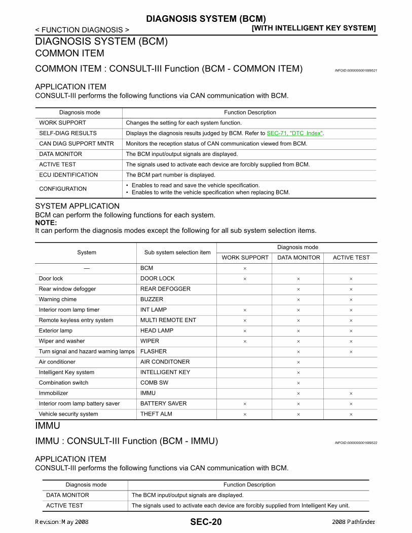
Is the inspection result normal?YES >> GO TO 4NO >> Repair or replace fuse or harness.
4.CHECK NATS ANTENNA AMP. GROUND LINE CIRCUIT
1. Turn ignition switch OFF.2. Disconnect NATS antenna amp. connector.3. Check continuity between NATS antenna amp. connector M21 terminal 3 and ground.
Is the inspection result normal?YES >> GO TO 5NO >> • Repair or replace harness.
NOTE:If harness is OK, replace BCM, perform initializationwith CONSULT-III. For initialization, refer to “CON-SULT-III Operation Manual”.
5.CHECK NATS ANTENNA AMP. SIGNAL LINE- 1
1. Connect NATS antenna amp. connector.2. Turn ignition switch ON.3. Check voltage between NATS antenna amp. connector M21 ter-
minal 2 and ground with analog tester.
Is the inspection result normal?YES >> GO TO 6NO >> • Repair or replace harness.
NOTE:If harness is OK, replace BCM, perform initialization with CONSULT-III. For initialization, refer to“CONSULT-III Operation Manual”.
1 - Ground : Battery voltage
LIIA1280E
3 - Ground : Continuity should exist.
LIIA1283E
LIIA1281E
TerminalsPosition of ignition key cylinder Voltage (V)
(Approx.)( + ) ( - )
2 Ground
Before inserting ignition key Battery voltage
After inserting ignition key Pointer of tester should move for approx. 30 seconds, then return to battery voltage
Just after turning ignition switch ON
Pointer of tester should move for approx. 1 second, then return to battery voltage
SEC-32

B2190, P1614 NATS ANTENNA AMP.[WITH INTELLIGENT KEY SYSTEM]
C
D
E
F
G
H
I
J
L
M
A
B
EC
N
O
P
< COMPONENT DIAGNOSIS >
S
6.CHECK NATS ANTENNA AMP. SIGNAL LINE- 2
Check voltage between NATS antenna amp. connector M21 terminal4 and ground with analog tester.
Is the inspection result normal?YES >> NATS antenna amp. is malfunctioning.NO >> • Repair or replace harness.
NOTE:If harness is OK, replace BCM, refer to BCS-54, "Removal and Installation". Perform initializa-tion with CONSULT-III. For initialization, refer to “CONSULT-III Operation Manual”.
LIIA1282E
TerminalsPosition of ignition key cylinder Voltage (V)
(Approx.)( + ) ( - )
4 Ground
Before inserting ignition key Battery voltage
After inserting ignition key Pointer of tester should move for approx. 30 seconds, then return to battery voltage
Just after turning ignition switch ON
Pointer of tester should move for approx. 1 second, then return to battery voltage
SEC-33

[WITH INTELLIGENT KEY SYSTEM]B2191, P1615 DIFFERENCE OF KEY
< COMPONENT DIAGNOSIS >B2191, P1615 DIFFERENCE OF KEYDescription INFOID:0000000001689538
Performs ID verification through BCM when ignition knob switch is pressed.Prohibits the release of steering lock or start of engine when an unregistered ID of mechanical key is used.
DTC Logic INFOID:0000000001689539
DTC DETECTION LOGIC
DTC CONFIRMATION PROCEDURE1.PERFORM DTC CONFIRMATION PROCEDURE
1. Insert mechanical key into the key cylinder.2. Press the ignition knob switch.3. Check “Self diagnostic result” with CONSULT-III.Is DTC detected?YES >> Refer toSEC-34, "Diagnosis Procedure".NO >> INSPECTION END.
Diagnosis Procedure INFOID:0000000001689540
1.PERFORM INITIALIZATION
Perform initialization with CONSULT-III. Re-register all mechanical keys.For initialization and registration of mechanical key. Refer to “CONSULT-III Operation Manual”.Can the system be initialized and can the engine be started with re-registered mechanical key?YES >> Mechanical key was unregistered.NO >> BCM is malfunctioning.
• Replace BCM. Refer to BCS-54, "Removal and Installation".• Perform initialization again
DTC No. Trouble diagnosis name DTC detecting condition Possible cause
B2191 DIFFERENCE OF KEY
The ID verification results between BCM and me-chanical key are NG. The registration is necessary. Mechanical key
P1615
SEC-34

B2192, P1611 ID DISCORD, IMMU-ECM[WITH INTELLIGENT KEY SYSTEM]
C
D
E
F
G
H
I
J
L
M
A
B
EC
N
O
P
< COMPONENT DIAGNOSIS >
S
B2192, P1611 ID DISCORD, IMMU-ECMDescription INFOID:0000000001689541
BCM performs the ID verification with ECM that allows the engine to start. BCM starts the communication withECM if ignition switch is turned ON and starts the engine if the ID is OK. ECM prevents the engine from start-ing if the ID is not registered.
DTC Logic INFOID:0000000001689542
DTC DETECTION LOGICNOTE:• If DTC B2192 is displayed with DTC U1000, first perform the trouble diagnosis for DTC U1000. Refer to
SEC-26, "DTC Logic".• If DTC B2192 is displayed with DTC U1010, first perform the trouble diagnosis for DTC U1010. Refer to
SEC-27, "DTC Logic".
DTC CONFIRMATION PROCEDURE1.PERFORM DTC CONFIRMATION PROCEDURE
1. Turn ignition switch ON.2. Check “Self diagnostic result” with CONSULT-III.Is DTC detected?YES >> Refer to SEC-35, "Diagnosis Procedure".NO >> INSPECTION END.
Diagnosis Procedure INFOID:0000000001689543
1.PERFORM INITIALIZATION
Perform initialization with CONSULT-III. Re-register all mechanical keys.For initialization and registration of mechanical key. Refer to “CONSULT-III Operation Manual”.Can the system be initialized and can the engine be started with re-registered mechanical key?YES >> ID was unregistered.NO >> GO TO 2
2.PEPLACE BCM
1. Replace BCM. Refer to BCS-54, "Removal and Installation".2. Perform initialization with CONSULT-III. Re-register all mechanical keys.
For initialization and registration of mechanical key. Refer to “CONSULT-III Operation Manual”.Can the system be initialized and can the engine be started with re-registered mechanical key?YES >> BCM is malfunctioning.NO >> GO TO 3
3.PEPLACE ECM
1. Replace ECM. Refer to Removal and Installation.2. Perform initialization with CONSULT-III. Re-register all mechanical keys.
For initialization and registration of mechanical key. Refer to “CONSULT-III Operation Manual”.Can the system be initialized and can the engine be started with re-registered mechanical key?YES >> ECM is malfunctioning.NO >> GO TO 4
4.CHECK INTERMITENT INCIDENT
Refer to GI-51, "Intermittent Incident".
DTC No. Trouble diagnosis name DTC detecting condition Possible cause
B2192 ID DISCORD BCM-ECM
The ID verification results between BCM and ECM are NG. The registration is necessary.
• BCM• ECMP1611
SEC-35

[WITH INTELLIGENT KEY SYSTEM]B2192, P1611 ID DISCORD, IMMU-ECM
< COMPONENT DIAGNOSIS >
>> INSPECTION END
SEC-36

B2193, P1612 CHAIN OF ECM-IMMU[WITH INTELLIGENT KEY SYSTEM]
C
D
E
F
G
H
I
J
L
M
A
B
EC
N
O
P
< COMPONENT DIAGNOSIS >
S
B2193, P1612 CHAIN OF ECM-IMMUDescription INFOID:0000000001689544
BCM performs the ID verification with ECM that allows the engine to start. BCM starts the communication withECM if ignition switch is turned ON and starts the engine if the ID is OK. ECM prevents the engine from start-ing if the ID is not registered.
DTC Logic INFOID:0000000001689545
DTC DETECTION LOGICNOTE:• If DTC B2193 is displayed with DTC U1000, first perform the trouble diagnosis for DTC U1000. Refer to
SEC-26, "DTC Logic".• If DTC B2193 is displayed with DTC U1010, first perform the trouble diagnosis for DTC U1010. Refer to
SEC-27, "DTC Logic".
DTC CONFIRMATION PROCEDURE1.PERFORM DTC CONFIRMATION PROCEDURE
1. Turn ignition switch ON.2. Check “Self diagnostic result” with CONSULT-III.Is DTC detected?YES >> Refer to SEC-37, "Diagnosis Procedure".NO >> INSPECTION END
Diagnosis Procedure INFOID:0000000001689546
1.REPLACE BCM
1. Replace BCM. Refer to BCS-54, "Removal and Installation".2. Perform initialization with CONSULT-III.
For initialization, refer to “CONSULT-III Operation Manual”.Does the engine start?YES >> BCM was malfunctioning.NO >> ECM is malfunctioning.
• Replace ECM.• Perform ECM re-communicating function.
DTC No. Trouble diagnosis name DTC detecting condition Possible cause
B2193
CHAIN OF BCM-ECM Inactive communication between ECM and BCM
• Harness or connectors(The CAN communication line is open or short)
• BCM• ECM
P1612
SEC-37
[WITH INTELLIGENT KEY SYSTEM]B2194 ID DISCORD IMMU-I-KEY
< COMPONENT DIAGNOSIS >B2194 ID DISCORD IMMU-I-KEYDescription INFOID:0000000001689547
BCM performs the ID verification with Intelligent Key unit that allows the engine to start. BCM starts the com-munication with Intelligent Key unit if ignition switch is turned ON and starts the engine if the ID is OK. BCMprevents the engine from starting if the ID is not registered.
DTC Logic INFOID:0000000001689548
DTC DETECTION LOGIC
DTC CONFIRMATION PROCEDURE1.PERFORM DTC CONFIRMATION PROCEDURE
1. Turn ignition switch ON.2. Check “Self diagnostic result” with CONSULT-III.Is DTC detected?YES >> Refer to SEC-38, "Diagnosis Procedure".NO >> INSPECTION END.
Diagnosis Procedure INFOID:0000000001689549
1.PERFORM INITIALIZATION
1. Perform initialization with CONSULT-III. Re-register all mechanical keys.For initialization and registration of mechanical key. Refer to “CONSULT-III Operation Manual”.
2. Check “Self diagnostic result” with CONSULT-III.Is DTC detected?YES >> GO TO 2NO >> ID was unregistered.
2.REPLACE BCM
1. Turn ignition switch OFF.2. Replace BCM. Refer to BCS-54, "Removal and Installation".3. Perform initialization with CONSULT-III. Re-register all mechanical keys.
For initialization and registration of mechanical key. Refer to “CONSULT-III Operation Manual”.Can the system be initialized and can the engine be started?YES >> BCM is malfunctioning.NO >> GO TO 3
3.CHECK INTERMITTENT INCIDENT
Refer to GI-51, "Intermittent Incident".
>> INSPECTION END
DTC No. Trouble diagnosis name DTC detecting condition Possible cause
B2194 DISCORD BCM-I-KEY
The ID verification results between BCM and Intel-ligent Key unit are NG. The registration is neces-sary.
• BCM• Intelligent Key unit
SEC-38

B2552 INTELLIGENT KEY[WITH INTELLIGENT KEY SYSTEM]
C
D
E
F
G
H
I
J
L
M
A
B
EC
N
O
P
< COMPONENT DIAGNOSIS >
S
B2552 INTELLIGENT KEYDescription INFOID:0000000001689550
Intelligent key unit performs engine start operation and steering lock control by crosschecking ID with the Intel-ligent key.
DTC Logic INFOID:0000000001689551
DTC DETECTION LOGIC
DTC CONFIRMATION PROCEDURE1.PERFORM DTC CONFIRMATION PROCEDURE
1. Turn ignition switch ON.2. Check “Self diagnostic result” with CONSULT-III.Is DTC detected?YES >> Refer to SEC-39, "Diagnosis Procedure".NO >> INSPECTION END.
Diagnosis Procedure INFOID:0000000001689552
1.REPLACE INTELLIGENT KEY UNIT
1. Replace Intelligent Key unit.2. Perform initialization with CONSULT-III. Re-register all mechanical keys. Refer to “CONSULT-III Opera-
tion Manual”.3. Start the engine.Does the engine start?YES >> INSPECTION ENDNO >> Perform “DTC confirmation procedure”. Refer to SEC-39, "DTC Logic".
Special Repair Requirement INFOID:0000000001689553
1.REQUIRED WORK WHEN REPLACING INTELLIGENT KEY UNIT
Initialize control unit. Refer to CONSULT-III Operation Manual.
>> Work end.
DTC No. Trouble diagnosis name DTC detecting condition Possible cause
B2552 INTELLIGENT KEY UNIT
Malfunction is detected inside Intelligent key unit. Intelligent Key unit
SEC-39

[WITH INTELLIGENT KEY SYSTEM]B2590 ID DISCORD BCM-I-KEY
< COMPONENT DIAGNOSIS >B2590 ID DISCORD BCM-I-KEYDescription INFOID:0000000001689554
Intelligent Key unit performs the ID verification with BCM that allows the engine to start. BCM starts the engineif the ID is OK and prevents the engine from starting if the ID is not registered.
DTC Logic INFOID:0000000001689555
DTC DETECTION LOGICNOTE:• If DTC B2590 is displayed with DTC U1000, first perform the trouble diagnosis for DTC U1000. Refer to
SEC-26, "DTC Logic".• If DTC B2590 is displayed with DTC U1010, first perform the trouble diagnosis for DTC U1010. Refer to
SEC-27, "DTC Logic".
DTC CONFIRMATION PROCEDURE1.PERFORM DTC CONFIRMATION PROCEDURE
1. Turn ignition switch ON.2. Check “Self diagnostic result” with CONSULT-III.Is DTC detected?YES >> Refer to SEC-40, "Diagnosis Procedure".NO >> INSPECTION END
Diagnosis Procedure INFOID:0000000001689556
1.PERFORM INITIALIZATION
Perform initialization with CONSULT-III. Re-register all mechanical keys.For initialization and registration of mechanical key. Refer to “CONSULT-III Operation Manual”.Can the system be initialized and can the engine be started with re-registered mechanical key?YES >> ID was unregistered.NO >> BCM is malfunctioning.
• Replace BCM. Refer to REMOVAL PROCEDURE.• Perform initialization again
DTC No. Trouble diagnosis name DTC detecting condition Possible cause
B2590 ID DISCORD BCM-I-KEY
The ID verification results between BCM and Intel-ligent Key unit are NG. The registration is neces-sary.
• BCM• Intelligent Key unit
SEC-40

P1610 LOCK MODE[WITH INTELLIGENT KEY SYSTEM]
C
D
E
F
G
H
I
J
L
M
A
B
EC
N
O
P
< COMPONENT DIAGNOSIS >
S
P1610 LOCK MODEDescription INFOID:0000000001689557
When the starting operation is carried more than five times consecutively under the following conditions, NATSwill shift to the mode which prevents the engine from being started.• Unregistered mechanical key is used.• BCM or ECM's malfunctioning.
DTC Logic INFOID:0000000001689558
DTC DETECTION LOGIC
DTC CONFIRMATION PROCEDURE1.PERFORM DTC CONFIRMATION PROCEDURE
1. Turn ignition switch ON.2. Check “Self diagnostic result” with CONSULT-III.Is DTC detected?YES >> Refer to SEC-41, "Diagnosis Procedure".NO >> INSPECTION END
Diagnosis Procedure INFOID:0000000001689559
1.CHECK ENGINE START FUNCTION
1. Perform the check for DTC except DTC P1610.2. Use CONSULT-III to erase DTC after fixing.3. Check that engine can start with registered mechanical key.Does the engine start?YES >> INSPECTION ENDNO >> GO TO 2
2.CHECK INTERMITTENT INCIDENT
Refer to GI-51, "Intermittent Incident".
>> INSPECTION END
DTC No. Trouble diagnosis name DTC detecting condition Possible cause
P1610 LOCK MODE
When the starting operation is carried out five or more times consecutively under the following conditions.• Unregistered mechanical key• BCM or ECM's malfunctioning.
—
SEC-41

[WITH INTELLIGENT KEY SYSTEM]POWER SUPPLY AND GROUND CIRCUIT
< COMPONENT DIAGNOSIS >POWER SUPPLY AND GROUND CIRCUITINTELLIGENT KEY UNITINTELLIGENT KEY UNIT : Diagnosis Procedure INFOID:0000000001689560
Refer to DLK-46, "INTELLIGENT KEY UNIT : Diagnosis Procedure".BCMBCM : Diagnosis Procedure INFOID:0000000001689561
Refer to BCS-32, "Diagnosis Procedure".
SEC-42

KEY CYLINDER SWITCH[WITH INTELLIGENT KEY SYSTEM]
C
D
E
F
G
H
I
J
L
M
A
B
EC
N
O
P
< COMPONENT DIAGNOSIS >
S
KEY CYLINDER SWITCHDescription INFOID:0000000001728777
The main power window and door lock/unlock switch detects condition of the door key cylinder switch andtransmits to BCM as the LOCK or UNLOCK signal.
Component Function Check INFOID:0000000001728778
1.CHECK DOOR KEY CYLINDER SWITCH INPUT SIGNAL
Check "KEY CYL LK-SW" AND "KEY CYL UN-SW" in DATA MONITOR mode for “POWER DOOR LOCKSYSTEM” with CONSULT-III.
Is the inspection result normal?YES >> Key cylinder switch is OK.NO >> Refer to SEC-43, "Diagnosis Procedure".
Diagnosis Procedure INFOID:0000000001728779
1.CHECK DOOR KEY CYLINDER SWITCH LH
With CONSULT-IIICheck front door lock assembly LH (key cylinder switch) ("KEY CYL LK-SW") and ("KEY CYL UN-SW) inDATA MONITOR mode with CONSULT–III.• When key inserted in left front key cylinder is turned to LOCK:
• When key inserted in left front key cylinder is turned to UNLOCK:
Without CONSULT-IIICheck voltage between main power window and door lock/unlockswitch connector D7 terminals 4, 6 and ground.
Is the inspection result normal?YES >> Key cylinder switch signal is OK.NO >> GO TO 2.
2.CHECK DOOR KEY CYLINDER SWITCH LH GROUND HARNESS
1. Turn ignition switch OFF.2. Disconnect front door lock assembly LH (key cylinder switch).
Monitor item Condition
KEY CYL LK-SWLock : ON
Neutral / Unlock : OFF
KEY CYL UN-SWUnlock : ON
Neutral / Lock : OFF
KEY CYL LK-SW : ON
KEY CYL UN-SW : ON
ConnectorTerminals
Condition of left front key cylinder Voltage (V)(Approx.)(+) (–)
D7
4
Ground
Neutral/Unlock 5
Lock 0
6 Neutral/Lock 5
Unlock 0LIIA0566E
SEC-43

[WITH INTELLIGENT KEY SYSTEM]KEY CYLINDER SWITCH
< COMPONENT DIAGNOSIS >3. Check continuity between front door lock assembly LH (key cyl-
inder switch) connector (A) D14 terminal 4 and body ground.
Is the inspection result normal?YES >> GO TO 3.NO >> Repair or replace harness.
3.CHECK DOOR KEY CYLINDER SWITCH LH
Check continuity between front door lock assembly LH (key cylinderswitch) terminals.
Is the inspection result normal?YES >> GO TO 4.NO >> Replace front door lock assembly LH (key cylinder switch). Refer to DLK-190, "Removal and
Installation".4.CHECK DOOR KEY CYLINDER HARNESS
Check continuity between main power window and door lock/unlockswitch connector (A) D7 terminals 4, 6 and front door lock assemblyLH (key cylinder switch) connector (B) D14 terminals 3, 5 and bodyground.
Is the inspection result normal?YES >> Replace main power window and door lock/unlock switch.NO >> Repair or replace harness.
Connector Terminals Continuity
D14 4 – Ground Yes
ALKIA1186ZZ
Terminals Condition Continuity
3 – 4Key is turned to LOCK or neutral. No
Key is turned to UNLOCK. Yes
4 – 5Key is turned to UNLOCK or neutral. No
Key is turned to LOCK. Yes
ALKIA1183ZZ
Connector Terminals Connector Terminals Continuity
A: Main power win-dow and door lock/
unlock switch
4 B: Front door lock assembly LH (key cylinder switch)
5 Yes
6 3 Yes
4, 6 Ground No
ALKIA1184ZZ
SEC-44

GLASS HATCH AJAR SWITCH[WITH INTELLIGENT KEY SYSTEM]
C
D
E
F
G
H
I
J
L
M
A
B
EC
N
O
P
< COMPONENT DIAGNOSIS >
S
GLASS HATCH AJAR SWITCHDiagnosis Procedure INFOID:0000000001733165
1.CHECK GLASS HATCH AJAR SWITCH INPUT SIGNAL
With CONSULT-IIICheck glass hatch ajar switch ("TRNK OPN MNTR") in DATA MONITOR mode with CONSULT–III.• When glass hatch is open:
• When glass hatch is closed:
Without CONSULT-IIICheck voltage between BCM connector M19 terminal 42 and ground.
Is the inspection result normal?YES >> System is OK.NO >> GO TO 2
2.CHECK GLASS HATCH AJAR SWITCH CIRCUIT
1. Turn ignition switch OFF.2. Disconnect BCM and glass hatch ajar switch.3. Check continuity between BCM connector M19 terminal 42 and glass hatch ajar switch connector D503
terminal 1 (+) .
4. Check continuity between glass hatch ajar switch connectorD503 terminal 1 (+) and ground.
Is the inspection result normal?YES >> GO TO 3NO >> Repair or replace harness.
3.CHECK GLASS HATCH AJAR SWITCH
Check continuity between glass hatch ajar switch connector terminal1 and ground.
Is the inspection result normal?YES >> Check glass hatch ajar switch case ground condition.NO >> Replace glass hatch ajar switch.
TRNK OPN MNTR : ON
TRNK OPN MNTR : OFF
Connector ItemTerminals
Condition Voltage (V)(Approx.)(+) (–)
M19 BCM 42 GroundOpen↓
Closed
0↓
Battery voltage
LIIA1149E
42 - 1 (+) : Continuity should exist.
1 (+) - Ground : Continuity should not exist.
LIIA1150E
Terminals Condition Continuity
Glass hatch ajar switch 1 – Ground
Open Yes
Closed No
ALKIA0668ZZ
SEC-45

[WITH INTELLIGENT KEY SYSTEM]IGNITION KNOB SWITCH
< COMPONENT DIAGNOSIS >IGNITION KNOB SWITCHIgnition Knob Switch Check INFOID:0000000001728780
1.CHECK IGNITION KNOB SWITCH
With CONSULT-IIIDisplay “PUSH SW” on DATA MONITOR screen, and check if ON/OFF display is linked to ignition switch oper-ation.
Without CONSULT-III1. Turn ignition switch OFF.2. Disconnect Intelligent Key unit connector.3. Check voltage between Intelligent Key unit harness connector
M164 terminal 27 and ground.
Is the inspection result normal?YES >> Ignition knob switch is OK.NO >> GO TO 2.
2.CHECK IGNITION KNOB SWITCH POWER SUPPLY CIRCUIT
1. Turn ignition switch OFF.2. Disconnect key switch and ignition knob switch connector.3. Check voltage between key switch and ignition knob switch harness connector M66 terminal 1 and
ground.
Is the inspection result normal?YES >> GO TO 3.NO >> Repair or replace key switch and ignition knob switch
power supply circuit.
3.CHECK IGNITION KNOB SWITCH OPERATION
Check continuity between key switch and ignition knob switch terminals 1 and 2.
Monitor item Condition
PUSH SWIgnition switch is pushed: ON
Ignition switch is released: OFF
ConnectorTerminals
Condition Voltage (V)(Approx.)(+) (–)
M164 27 Ground
Ignition switch is pushed Battery voltage
Ignition switch is re-leased 0
WIIA1175E
1 - Ground : Battery voltage
ALKIA1217ZZ
SEC-46

IGNITION KNOB SWITCH[WITH INTELLIGENT KEY SYSTEM]
C
D
E
F
G
H
I
J
L
M
A
B
EC
N
O
P
< COMPONENT DIAGNOSIS >
S
Is the inspection result normal?YES >> GO TO 4.NO >> Replace key switch and ignition knob switch.
4.CHECK IGNITION KNOB SWITCH CIRCUIT
1. Check continuity between Intelligent Key unit harness connector (A) M164 terminal 27 and key switch andignition knob switch harness connector (B) M66 terminal 2.
2. Check continuity between Intelligent Key unit harness connectorM164 terminal 27 and ground.
Is the inspection result normal?YES >> Check the condition of harness and harness connector.NO >> Repair or replace harness between Intelligent Key unit
and key switch and ignition knob switch.
Component Terminals Condition Continuity
Ignition knob switch 1 2
Ignition switch is pushed Yes
Ignition switch is released No
ALKIA1218ZZ
27 - 2 : Continuity should exist.
27 - Ground : Continuity should not exist.
ALKIA1219ZZ
SEC-47

[WITH INTELLIGENT KEY SYSTEM]HORN FUNCTION
< COMPONENT DIAGNOSIS >HORN FUNCTIONSymptom Table INFOID:0000000001689566
HAZARD AND HORN REMINDER FUNCTION MALFUNCTIONNOTE:• Before performing the diagnosis in the following table, check “Work flow”. Refer to SEC-5, "Work Flow".• If the following symptoms” are detected, check systems shown in the “Diagnosis/service procedure” column
in this order.Conditions of Vehicle (Operating Conditions)• “ANSWER BACK FUNCTION” is ON when setting on CONSULT-III.• Ignition switch is in OFF position.• All doors are closed.
Symptom Diagnosis/service procedure Reference page
Hazard reminder does not operate by request switch.(Horn reminder operate.)
1. Check “HAZARD ANSWER BACK” setting in “WORK SUPPORT”. SEC-20
2. Check hazard function. EXL-4
3. Check Intermittent Incident. GI-51
Hazard reminder does not operate by Intelligent Key.(Horn reminder operate.)
1. Check “HAZARD ANSWER BACK” setting in “WORK SUPPORT”. SEC-20
2. Check hazard function. EXL-4
3. Check Intelligent Key battery inspection. DLK-87
Horn reminder does not operate by request switch.(Hazard reminder operate.)
1.Check “ANSWER BACK WITH I-KEY LOCK” or “AN-SWER BACK WITH I-KEY UNLOCK” setting in “WORK SUPPORT”.
SEC-20
2. Check Intelligent Key warning buzzer. DLK-73
3. Check Intermittent Incident. GI-51
Horn reminder does not operate by Intelligent Key.(Hazard reminder operate.)
1. Check “HORN WITH KEYLESS LOCK” setting in “WORK SUPPORT”. SEC-20
2. Check horn function. HRN-3
3. Check Intermittent Incident. GI-51
SEC-48

VEHICLE SECURITY INDICATOR[WITH INTELLIGENT KEY SYSTEM]
C
D
E
F
G
H
I
J
L
M
A
B
EC
N
O
P
< COMPONENT DIAGNOSIS >
S
VEHICLE SECURITY INDICATORDescription INFOID:0000000001689567
• Vehicle security indicator is built in combination meter.• NATS (Nissan Anti-Theft System) and vehicle security system conditions are indicated by blink or illumina-
tion of vehicle security indicator.
Component Function Check INFOID:0000000001689568
1.CHECK FUNCTION
1. Perform “THEFT IND” in the “Active Test” mode with CONSULT-III.2. Check vehicle security indicator operation.
Is the inspection result normal?YES >> INSPECTION END.NO >> Refer to SEC-49, "Diagnosis Procedure".
Diagnosis Procedure INFOID:0000000001689569
1.SECURITY INDICATOR LAMP ACTIVE TEST
With CONSULT-IIICheck "THEFT IND” in "ACTIVE TEST" mode with CONSULT-III.
Without CONSULT-III1. Disconnect BCM.2. Check voltage between BCM harness connector M18 terminal
23 and ground.
Is the inspection result normal?YES >> Security indicator lamp is OK.NO >> GO TO 2
2.SECURITY INDICATOR LAMP CHECK
Check security indicator lamp condition.Is the inspection result normal?YES >> GO TO 3NO >> Replace security indicator lamp.
3.CHECK HARNESS CONTINUITY
1. Turn ignition switch OFF.2. Disconnect BCM and security indicator lamp connector.
Test item Description
THEFT INDON
Vehicle security indicatorON
OFF OFF
ConnectorTerminals
Condition Voltage (V)(Approx.)(+) (-)
M18 23 GroundON 0
OFF Battery voltage
LIIA0523E
SEC-49
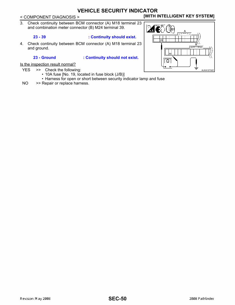
[WITH INTELLIGENT KEY SYSTEM]VEHICLE SECURITY INDICATOR
< COMPONENT DIAGNOSIS >3. Check continuity between BCM connector (A) M18 terminal 23
and combination meter connector (B) M24 terminal 39.
4. Check continuity between BCM connector (A) M18 terminal 23and ground.
Is the inspection result normal?YES >> Check the following:
• 10A fuse [No. 19, located in fuse block (J/B)]• Harness for open or short between security indicator lamp and fuse
NO >> Repair or replace harness.
23 - 39 : Continuity should exist.
23 - Ground : Continuity should not exist.
ALKIA1273ZZ
SEC-50

BCM (BODY CONTROL MODULE)[WITH INTELLIGENT KEY SYSTEM]
C
D
E
F
G
H
I
J
L
M
A
B
EC
N
O
P
< ECU DIAGNOSIS >
S
ECU DIAGNOSISBCM (BODY CONTROL MODULE)Reference Value INFOID:0000000001689570
VALUES ON THE DIAGNOSIS TOOLRefer to BCS-38, "Reference Value".
TERMINAL LAYOUTRefer to BCS-41, "Terminal Layout".
PHYSICAL VALUESRefer to BCS-41, "Physical Values".
SEC-51

[WITH INTELLIGENT KEY SYSTEM]BCM (BODY CONTROL MODULE)
< ECU DIAGNOSIS >Wiring Diagram - VEHICLE SECURITY SYSTEM INFOID:0000000001689571
AWKWA0067G
SEC-52

BCM (BODY CONTROL MODULE)[WITH INTELLIGENT KEY SYSTEM]
C
D
E
F
G
H
I
J
L
M
A
B
EC
N
O
P
< ECU DIAGNOSIS >
S
AWKWA0068G
SEC-53

[WITH INTELLIGENT KEY SYSTEM]BCM (BODY CONTROL MODULE)
< ECU DIAGNOSIS >
AWKIA0262GB
SEC-54

BCM (BODY CONTROL MODULE)[WITH INTELLIGENT KEY SYSTEM]
C
D
E
F
G
H
I
J
L
M
A
B
EC
N
O
P
< ECU DIAGNOSIS >
S
AWKIA0263GB
SEC-55

[WITH INTELLIGENT KEY SYSTEM]BCM (BODY CONTROL MODULE)
< ECU DIAGNOSIS >
AWKIA0264GB
SEC-56

BCM (BODY CONTROL MODULE)[WITH INTELLIGENT KEY SYSTEM]
C
D
E
F
G
H
I
J
L
M
A
B
EC
N
O
P
< ECU DIAGNOSIS >
S
AWKIA0265GB
SEC-57

[WITH INTELLIGENT KEY SYSTEM]BCM (BODY CONTROL MODULE)
< ECU DIAGNOSIS >
AWKIA0266GB
SEC-58

BCM (BODY CONTROL MODULE)[WITH INTELLIGENT KEY SYSTEM]
C
D
E
F
G
H
I
J
L
M
A
B
EC
N
O
P
< ECU DIAGNOSIS >
S
AWKIA0267GB
SEC-59
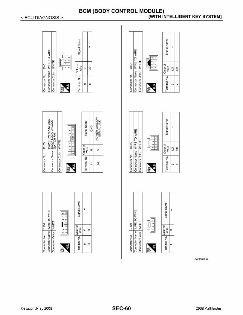
[WITH INTELLIGENT KEY SYSTEM]BCM (BODY CONTROL MODULE)
< ECU DIAGNOSIS >
AWKIA0268GB
SEC-60

BCM (BODY CONTROL MODULE)[WITH INTELLIGENT KEY SYSTEM]
C
D
E
F
G
H
I
J
L
M
A
B
EC
N
O
P
< ECU DIAGNOSIS >
S
AWKIA0269GB
SEC-61

[WITH INTELLIGENT KEY SYSTEM]BCM (BODY CONTROL MODULE)
< ECU DIAGNOSIS >Wiring Diagram - NVIS INFOID:0000000001689572
AWKWA0064G
SEC-62

BCM (BODY CONTROL MODULE)[WITH INTELLIGENT KEY SYSTEM]
C
D
E
F
G
H
I
J
L
M
A
B
EC
N
O
P
< ECU DIAGNOSIS >
S
AWKWA0065G
SEC-63

[WITH INTELLIGENT KEY SYSTEM]BCM (BODY CONTROL MODULE)
< ECU DIAGNOSIS >
AWKWA0066G
SEC-64

BCM (BODY CONTROL MODULE)[WITH INTELLIGENT KEY SYSTEM]
C
D
E
F
G
H
I
J
L
M
A
B
EC
N
O
P
< ECU DIAGNOSIS >
S
AWKIA0256GB
SEC-65

[WITH INTELLIGENT KEY SYSTEM]BCM (BODY CONTROL MODULE)
< ECU DIAGNOSIS >
AWKIA0257GB
SEC-66

BCM (BODY CONTROL MODULE)[WITH INTELLIGENT KEY SYSTEM]
C
D
E
F
G
H
I
J
L
M
A
B
EC
N
O
P
< ECU DIAGNOSIS >
S
AWKIA0258GB
SEC-67

[WITH INTELLIGENT KEY SYSTEM]BCM (BODY CONTROL MODULE)
< ECU DIAGNOSIS >
AWKIA0259GB
SEC-68

BCM (BODY CONTROL MODULE)[WITH INTELLIGENT KEY SYSTEM]
C
D
E
F
G
H
I
J
L
M
A
B
EC
N
O
P
< ECU DIAGNOSIS >
S
AWKIA0260GB
SEC-69

[WITH INTELLIGENT KEY SYSTEM]BCM (BODY CONTROL MODULE)
< ECU DIAGNOSIS >
AWKIA0261GB
SEC-70

BCM (BODY CONTROL MODULE)[WITH INTELLIGENT KEY SYSTEM]
C
D
E
F
G
H
I
J
L
M
A
B
EC
N
O
P
< ECU DIAGNOSIS >
S
Fail Safe INFOID:0000000001689573
DTC Inspection Priority Chart INFOID:0000000001689574
If some DTCs are displayed at the same time, perform inspections one by one based on the following prioritychart.
DTC Index INFOID:0000000001689575
NOTE:Details of time display
• CRNT: Displays when there is a malfunction now or after returning to the normal condition until turning igni-tion switch OFF → ON again.
• 1 - 39: Displayed if any previous malfunction is present when current condition is normal. It increases like 1→ 2 → 3...38 → 39 after returning to the normal condition whenever ignition switch OFF → ON. The counterremains at 39 even if the number of cycles exceeds it. It is counted from 1 again when turning ignition switchOFF → ON after returning to the normal condition if the malfunction is detected again.
Display contents of CONSULT-III Fail-safe Cancellation
B2013: STRG COMM 1 • Inhibits steering look unlocking Erase DTC
B2552: INTELLIGENT KEY
• Inhibits steering look unlocking• Inhibits engine cranking
(BCM)• Fuel cut
(ECM)
Erase DTC
B2590: NATS MALFUNCTION
• Inhibits steering look unlocking• Inhibits engine cranking
(BCM)• Fuel cut
(ECM)
Erase DTC
Priority DTC
1• U1000: CAN COMM CIRCUIT• U1010: CONTROL UNIT (CAN)• B2552: INTELLIGENT KEY
2 • B2013: STRG COMM 1• B2590: NATS MALFUNCTION
CONSULT display Detection condition Fail-safe Diagnosis
No DTC is detected.further testingmay be required.
— — —
U1000: CAN COMM CIRCUIT Intelligent Key unit cannot receive CAN communi-cation signal continuously for 2 seconds or more. —
Check CAN communi-cation system.Refer to SEC-26
U1010: CONTROL UNIT (CAN) Intelligent Key unit detects internal CAN communi-cation circuit malfunction. — Replace Intelligent Key
unit.
B2013: STRG COMM 1
The ID verification result between Intelligent key unit and steering lock solenoid are NG. Or Intelligent Key unit cannot communicate with steering lock so-lenoid.
×Perform steering lock unit ID registration with CONSULT-III
B2552: INTELLIGENT KEY Intelligent Key unit internal malfunction. ×Replace Intelligent Key unit.
B2590: NATS MALFUNCTIONThe ID verification result between Intelligent key unit and BCM are NG. Or Intelligent Key unit cannot communicate with BCM.
×Check NATSRefer to SEC-40
SEC-71

[WITH INTELLIGENT KEY SYSTEM]INTELLIGENT KEY UNIT
< ECU DIAGNOSIS >INTELLIGENT KEY UNITReference Value INFOID:0000000001689576
VALUES ON THE DIAGNOSIS TOOLCONSULT-III MONITOR ITEM
TERMINAL LAYOUTRefer to DLK-131, "Reference Value - Intelligent Key Unit".
PHYSICAL VALUESRefer to DLK-131, "Reference Value - Intelligent Key Unit".
Monitor Item Condition Value/Status
PUSH SW Ignition knobRelease OFF
Press ON
KEY ON SW Mechanical keyRemoved OFF
Inserted ON
DR REQ SW Door request switch (driver)
Release OFF
Press ON
AS REQ SW Door request switch(passenger)
Release OFF
Press ON
BD/TR REQ SW Door request switch(back door)
Release OFF
Press ON
IGN SW Ignition switchOther than ON position OFF
ON position ON
ACC SW Ignition switchOther than ACC or ON position OFF
ACC or ON position ON
STOP LAMP SW Brake pedalPress OFF
Release ON
DOOR LOCK SIG Lock button of Intelligent Key
Release OFF
Press ON
DOOR UNLOCK SIG Unlock button of Intelligent Key
Release OFF
Press ON
DOOR SW DR Door (driver side)Close OFF
Open ON
DOOR SW AS Door (passenger side)Close OFF
Open ON
DOOR SW RR Door (rear RH)Close OFF
Open ON
DOOR SW RL Door (rear LH)Close OFF
Open ON
DOOR BK SW Back doorClose OFF
Open ON
VEHICLE SPEED While driving Equivalent to speedometer reading
SEC-72

INTELLIGENT KEY UNIT[WITH INTELLIGENT KEY SYSTEM]
C
D
E
F
G
H
I
J
L
M
A
B
EC
N
O
P
< ECU DIAGNOSIS >
S
Wiring Diagram - INTELLIGENT KEY SYSTEM/ENGINE START FUNCTION -INFOID:0000000001689577
AWKWA0059G
SEC-73

[WITH INTELLIGENT KEY SYSTEM]INTELLIGENT KEY UNIT
< ECU DIAGNOSIS >
AWKWA0060G
SEC-74

INTELLIGENT KEY UNIT[WITH INTELLIGENT KEY SYSTEM]
C
D
E
F
G
H
I
J
L
M
A
B
EC
N
O
P
< ECU DIAGNOSIS >
S
AWKWA0061G
SEC-75

[WITH INTELLIGENT KEY SYSTEM]INTELLIGENT KEY UNIT
< ECU DIAGNOSIS >
AWKIA0240GB
SEC-76

INTELLIGENT KEY UNIT[WITH INTELLIGENT KEY SYSTEM]
C
D
E
F
G
H
I
J
L
M
A
B
EC
N
O
P
< ECU DIAGNOSIS >
S
AWKIA0241GB
SEC-77

[WITH INTELLIGENT KEY SYSTEM]INTELLIGENT KEY UNIT
< ECU DIAGNOSIS >
AWKIA0242GB
SEC-78

INTELLIGENT KEY UNIT[WITH INTELLIGENT KEY SYSTEM]
C
D
E
F
G
H
I
J
L
M
A
B
EC
N
O
P
< ECU DIAGNOSIS >
S
AWKIA0243GB
SEC-79

[WITH INTELLIGENT KEY SYSTEM]INTELLIGENT KEY UNIT
< ECU DIAGNOSIS >
AWKIA0244GB
SEC-80

INTELLIGENT KEY UNIT[WITH INTELLIGENT KEY SYSTEM]
C
D
E
F
G
H
I
J
L
M
A
B
EC
N
O
P
< ECU DIAGNOSIS >
S
AWKIA0245GB
SEC-81

[WITH INTELLIGENT KEY SYSTEM]INTELLIGENT KEY UNIT
< ECU DIAGNOSIS >
AWKIA0246GB
SEC-82

INTELLIGENT KEY UNIT[WITH INTELLIGENT KEY SYSTEM]
C
D
E
F
G
H
I
J
L
M
A
B
EC
N
O
P
< ECU DIAGNOSIS >
S
AWKIA0247GB
SEC-83

[WITH INTELLIGENT KEY SYSTEM]INTELLIGENT KEY UNIT
< ECU DIAGNOSIS >
AWKIA0248GB
SEC-84

INTELLIGENT KEY UNIT[WITH INTELLIGENT KEY SYSTEM]
C
D
E
F
G
H
I
J
L
M
A
B
EC
N
O
P
< ECU DIAGNOSIS >
S
AWKIA0249GB
SEC-85

[WITH INTELLIGENT KEY SYSTEM]INTELLIGENT KEY UNIT
< ECU DIAGNOSIS >
AWKIA0250GB
SEC-86

INTELLIGENT KEY UNIT[WITH INTELLIGENT KEY SYSTEM]
C
D
E
F
G
H
I
J
L
M
A
B
EC
N
O
P
< ECU DIAGNOSIS >
S
Fail Safe INFOID:0000000001689578
DTC Inspection Priority Chart INFOID:0000000001689579
If some DTCs are displayed at the same time, perform inspections one by one based on the following prioritychart.
DTC Index INFOID:0000000001689580
NOTE:Details of time display
• CRNT: Displays when there is a malfunction now or after returning to the normal condition until turning igni-tion switch OFF → ON again.
• 1 - 39: Displayed if any previous malfunction is present when current condition is normal. It increases like 1→ 2 → 3...38 → 39 after returning to the normal condition whenever ignition switch OFF → ON. The counterremains at 39 even if the number of cycles exceeds it. It is counted from 1 again when turning ignition switchOFF → ON after returning to the normal condition if the malfunction is detected again.
Display contents of CONSULT-III Fail-safe Cancellation
B2013: STRG COMM 1 • Inhibits steering look unlocking Erase DTC
B2552: INTELLIGENT KEY
• Inhibits steering look unlocking• Inhibits engine cranking
(BCM)• Fuel cut
(ECM)
Erase DTC
B2590: NATS MALFUNCTION
• Inhibits steering look unlocking• Inhibits engine cranking
(BCM)• Fuel cut
(ECM)
Erase DTC
Priority DTC
1• U1000: CAN COMM CIRCUIT• U1010: CONTROL UNIT (CAN)• B2552: INTELLIGENT KEY
2 • B2013: STRG COMM 1• B2590: NATS MALFUNCTION
CONSULT display Detection condition Fail-safe Diagnosis
No DTC is detected.further testingmay be required.
— — —
U1000: CAN COMM CIRCUIT Intelligent Key unit cannot receive CAN communi-cation signal continuously for 2 seconds or more. —
Check CAN communi-cation system.Refer to SEC-26
U1010: CONTROL UNIT (CAN) Intelligent Key unit detects internal CAN communi-cation circuit malfunction. — Replace Intelligent Key
unit.
B2013: STRG COMM 1
The ID verification result between Intelligent key unit and steering lock solenoid are NG. Or Intelligent Key unit cannot communicate with steering lock so-lenoid.
×Perform steering lock unit ID registration with CONSULT-III
B2552: INTELLIGENT KEY Intelligent Key unit internal malfunction. ×Replace Intelligent Key unit.
B2590: NATS MALFUNCTIONThe ID verification result between Intelligent key unit and BCM are NG. Or Intelligent Key unit cannot communicate with BCM.
×Check NATSRefer to SEC-40
SEC-87

[WITH INTELLIGENT KEY SYSTEM]IPDM E/R (INTELLIGENT POWER DISTRIBUTION MODULE ENGINE ROOM)
< ECU DIAGNOSIS >IPDM E/R (INTELLIGENT POWER DISTRIBUTION MODULE ENGINEROOM)Reference Value INFOID:0000000001689581
VALUES ON THE DIAGNOSIS TOOLRefer to PCS-17, "Reference Value".
TERMINAL LAYOUTRefer to PCS-19, "Terminal Layout".
Fail Safe INFOID:0000000001689582
Refer to PCS-26, "Fail Safe".
DTC Index INFOID:0000000001689583
Refer to PCS-28, "DTC Index".
SEC-88

INTELLIGENT KEY SYSTEM/ENGINE START FUNCTION SYMPTOMS[WITH INTELLIGENT KEY SYSTEM]
C
D
E
F
G
H
I
J
L
M
A
B
EC
N
O
P
< SYMPTOM DIAGNOSIS >
S
SYMPTOM DIAGNOSISINTELLIGENT KEY SYSTEM/ENGINE START FUNCTION SYMPTOMSSymptom Table INFOID:0000000001689584
NOTE:• Before performing the diagnosis in the following table, check “SEC-5, "Work Flow"”. • Check that vehicle is under the condition shown in “Conditions of vehicle” before starting diagnosis, and
check each symptom.• Engine cranking is enabled when the shift lever is in the "Park" position, and in the "Neutral" position only if
the brake pedal is depressed.• If the following symptoms are detected, check systems shown in the “Diagnosis/service procedure” column
in this order.
CONDITIONS OF VEHICLE (OPERATING CONDITIONS)• Engine start function is ON when setting on CONSULT-III.• Mechanical key is not inserted in key cylinder.• One or more of Intelligent Keys with registered Intelligent Key ID is in the vehicle.
Symptom Diagnosis/service procedure Reference page
Ignition switch does not turn on with Intelligent Key.[green "KEY" lamp is displayed]
1. Check steering lock solenoid. SEC-28
2. Replace Intelligent Key unit. SEC-94
Ignition switch does not turn on with Intelligent Key.["KEY" lamp does not display]
1. Check Intelligent Key unit power supply and ground circuit. DLK-46
2. Check ignition knob switch. DLK-97
3. Check key switch (BCM input). DLK-96
4. Check key switch (Intelligent Key unit input). DLK-94
5. Replace Intelligent Key unit. SEC-94
6. Check green "KEY" indicator. DLK-76
7. Check red "KEY" indicator. DLK-76
Ignition switch does not turn on with Intelligent Key.[red "KEY" lamp is displayed]
1a. Check inside key antenna 1 (instrument panel). DLK-40
1b. Check inside key antenna 2 (luggage compartment). DLK-42
1c. Check inside key antenna 3 (center console). DLK-44
2. Replace Intelligent Key unit. SEC-94
Ignition switch does not turn on with mechanical key1. Check key switch (BCM input). DLK-96
2. Check key switch (Intelligent Key unit input). DLK-94
Engine cannot be cranked with transmission in "Park" or in "Neutral" position with brake pedal depressed
1. Check transmission signal. TM-51
2. Check stop lamp switch. EXL-80
"P-SHIFT" indicator does not operate properly 1. Check "P-SHIFT" indicator. DLK-76
SEC-89

[WITH INTELLIGENT KEY SYSTEM]VEHICLE SECURITY SYSTEM SYMPTOMS
< SYMPTOM DIAGNOSIS >VEHICLE SECURITY SYSTEM SYMPTOMSSymptom Table INFOID:0000000001689585
*: Check the system is in the armed phase.
ProcedureDiagnostic procedure Refer to page
Symptom
1
Vehicle security sys-tem cannot be set by ····
Door switch Check door switch (LF, RF, LR, RR, back) DLK-48
Glass ajar switch Check glass ajar switch SEC-45
Intelligent Key Check Intelligent Key system SEC-9
Key cylinder switch Check key cylinder switch SEC-43
— Check Intermittent Incident GI-51
Security indicator does not turn ON.Check vehicle security indicator SEC-49
Check Intermittent Incident GI-51
2* Vehicle security system does not sound alarm when ····
Any door is opened. Check door switch (LF, RF, LR, RR, back) DLK-48
Glass ajar switch Check glass ajar switch SEC-45
— Check Intermittent Incident GI-51
3Vehicle security alarm does not acti-vate.
Horn alarmCheck horn switch HRN-3
Check Intermittent Incident GI-51
4Vehicle security sys-tem cannot be can-celed by ····
Intelligent Key Check Intelligent Key system SEC-9
Key cylinder switch Check key cylinder switch SEC-43
— Check Intermittent Incident GI-51
SEC-90

NISSAN VEHICLE IMMOBILIZER SYSTEM-NATS SYMPTOMS[WITH INTELLIGENT KEY SYSTEM]
C
D
E
F
G
H
I
J
L
M
A
B
EC
N
O
P
< SYMPTOM DIAGNOSIS >
S
NISSAN VEHICLE IMMOBILIZER SYSTEM-NATS SYMPTOMSSymptom Table INFOID:0000000001689586
NOTE:• Before performing the diagnosis in the following table, check “SEC-5, "Work Flow"”. • Check that vehicle is under the condition shown in “Conditions of vehicle” before starting diagnosis, and
check each symptom.• If the following symptoms are detected, check systems shown in the “Diagnosis/service procedure” column
in this order.
CONDITIONS OF VEHICLE (OPERATING CONDITIONS)• Mechanical key is not inserted into key cylinder.• Ignition knob switch is not depressed.
Symptom Diagnosis/service procedure Reference page
Security indicator does not turn ON or flash.1. Check vehicle security indicator SEC-49
2. Check Intermittent Incident GI-51
SEC-91

[WITH INTELLIGENT KEY SYSTEM]PRE-INSPECTION FOR DIAGNOSTIC
< ON-VEHICLE MAINTENANCE >
ON-VEHICLE MAINTENANCEPRE-INSPECTION FOR DIAGNOSTICBasic Inspection INFOID:0000000001689587
The engine start function, door lock function, power distribution system and NATS-IVIS/NMS in the IntelligentKey system are closely related to each other regarding control. Narrow down the functional area in questionby performing basic inspection to identify which function is malfunctioning. The vehicle security function canoperate only when the door lock and power distribution system are operating normally. Therefore, it is easy toidentify any factor unique to the vehicle security system by performing the vehicle security operation checkafter basic inspection.1.CHECK DOOR LOCK OPERATION
1. Check the door lock for normal operation with the Intelligent Key controller and door request switch.Successful door lock operation with the Intelligent Key and request SW indicates that the remote keylessentry receiver and inside key antenna required for engine start are functioning normally.Identify the malfunctioning point by referring to the DLK section if the door cannot be unlocked.
Can the door be locked with the Intelligent Key and door request switch?YES >> GO TO 2.NO >> Refer to DLK-160, "Symptom Table".
2.CHECK ENGINE STARTING
1. Checks that the engine starts when operating the Intelligent Key.Does the engine start?YES >> GO TO 3.NO >> Refer to SEC-89, "Symptom Table".
3.CHECK STEERING LOCKING
1. Does the steering lock when operating door switch after switching the power supply from ON position (orACC position) to LOCK position?If door switch is malfunctioning, BCM cannot lock the steering. If BCM does not detect DTC, steering lockunit is normal.
Does steering lock?YES >> GO TO 4.NO >> Refer to DLK-80, "Diagnosis Procedure".
4.CHECK IGNITION KNOB SWITCH OPERATION
1. Press ignition knob to check switch operation.Does the combination meter display any message?YES >> GO TO 5.NO >> Refer to SEC-46, "Ignition Knob Switch Check".
5.CHECK VEHICLE SECURITY SYSTEM
1. Check the vehicle security system for normal operation.The vehicle security function can operate only when the door lock and power distribution functions areoperating normally. Therefore, it is easy to identify any factor unique to the vehicle security by performing the vehicle securityoperation check after this basic inspection.
>> Go to SEC-92, "Vehicle Security Operation Check".
Vehicle Security Operation Check INFOID:0000000001689588
1.INSPECTION START
Turn ignition switch “OFF”.NOTE:Before starting operation check, open front windows.
SEC-92

PRE-INSPECTION FOR DIAGNOSTIC[WITH INTELLIGENT KEY SYSTEM]
C
D
E
F
G
H
I
J
L
M
A
B
EC
N
O
P
< ON-VEHICLE MAINTENANCE >
S
>> GO TO 2.2.CHECK SECURITY INDICATOR LAMP
1. Lock doors using Intelligent Key or mechanical key.2. Check that security indicator lamp illuminates for 30 seconds.Security indicator lamp should illuminate.OK >> GO TO 3.NG >> Perform diagnosis and repair. Refer to SEC-49, "Diagnosis Procedure".
3.CHECK ALARM FUNCTION
1. After 30 seconds, security indicator lamp will start to blink.2. Open any door before unlocking with Intelligent Key or mechanical key, or open back door or glass hatch
without the presence of Intelligent Key.Does the alarm function properly?YES >> GO TO 4.NO >> Check the following.
• The vehicle security system does not phase in alarm mode. Refer to SEC-89, "Symptom Table".• Alarm (horn and headlamps) does not operate. Refer to SEC-89, "Symptom Table".
4.CHECK ALARM CANCEL OPERATION
Unlock any door using Intelligent Key or mechanical key.Alarm (horn and headlamps) should stop.OK >> INSPECTION END.NG >> Check door lock function. Refer to SEC-90, "Symptom Table".
SEC-93

[WITH INTELLIGENT KEY SYSTEM]INTELLIGENT KEY UNIT
< ON-VEHICLE REPAIR >
ON-VEHICLE REPAIRINTELLIGENT KEY UNITRemoval and Installation INFOID:0000000001689589
REMOTE KEYLESS ENTRY RECEIVERRemoval1. Remove the instrument panel. Refer to IP-10, "Removal and Installation".2. Disconnect the wire harness (1), remove the bolt (A) and the
RKE receiver (2).
InstallationInstallation is in the reverse order of removal.
INTELLIGENT KEY UNITRemoval1. Remove the instrument panel. Refer to IP-10, "Removal and Installation".2. Disconnect the wire harness (1), remove the bolt (A) and the
Intelligent key unit (2).
InstallationInstallation is in the reverse order of removal.
ALKIA0537ZZ
ALKIA0666ZZ
SEC-94

NATS ANTENNA AMP.[WITH INTELLIGENT KEY SYSTEM]
C
D
E
F
G
H
I
J
L
M
A
B
EC
N
O
P
< REMOVAL AND INSTALLATION >
S
REMOVAL AND INSTALLATIONNATS ANTENNA AMP.Removal and Installation INFOID:0000000001689649
NOTE:• If NATS antenna amp. is not installed correctly, NVIS (NATS) system will not operate properly and "SELF-
DIAG RESULTS' on CONSULT-III screen will show "LOCK MODE" or "CHAIN OF IMMU-KEY'.• Initilization is not necessary when only the NATS antenna amp. is replaced with a new one.
REMOVAL1. Disconnect the battery negative terminal.2. Remove cluster lid A. Refer to IP-10, "Exploded View".3. Remove the bolt, disconnect the electrical connector, and remove the NATS antenna amp.
INSTALLATIONInstallation is in the reverse order of removal.
SEC-95

[WITH INTELLIGENT KEY SYSTEM]INTELLIGENT KEY UNIT
< REMOVAL AND INSTALLATION >INTELLIGENT KEY UNITRemoval and Installation INFOID:0000000001689650
REMOVAL1. Disconnect the battery negative terminal.2. Remove the lower glove box. Refer to IP-10, "Exploded View".3. Remove the bolt (A), disconnect the electrical connector (1), and
remove the intelligent key module (2).
INSTALLATIONInstallation is in the reverse order of removal.
⇒: Front
ALKIA1059ZZ
SEC-96

REMOTE KEYLESS ENTRY RECEIVER[WITH INTELLIGENT KEY SYSTEM]
C
D
E
F
G
H
I
J
L
M
A
B
EC
N
O
P
< REMOVAL AND INSTALLATION >
S
REMOTE KEYLESS ENTRY RECEIVERRemoval INFOID:0000000001730844
1. Disconnect the battery negative cable.2. Remove the upper glove box. Refer to IP-10, "Exploded View".3. Remove the bolt, disconnect and remove the remote keyless entry receiver.
Installation INFOID:0000000001730845
Installation is in the reverse order of removal.
SEC-97

[WITHOUT INTELLIGENT KEY SYSTEM]DIAGNOSIS AND REPAIR WORKFLOW
< BASIC INSPECTION >
BASIC INSPECTIONDIAGNOSIS AND REPAIR WORKFLOWWork Flow INFOID:0000000001689590
OVERALL SEQUENCE
DETAILED FLOWALKIA0538GB
SEC-98
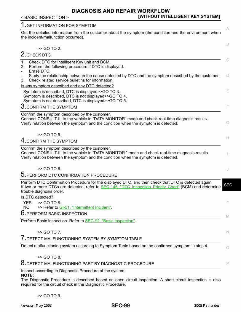
DIAGNOSIS AND REPAIR WORKFLOW[WITHOUT INTELLIGENT KEY SYSTEM]
C
D
E
F
G
H
I
J
L
M
A
B
EC
N
O
P
< BASIC INSPECTION >
S
1.GET INFORMATION FOR SYMPTOM
Get the detailed information from the customer about the symptom (the condition and the environment whenthe incident/malfunction occurred).
>> GO TO 2.2.CHECK DTC
1. Check DTC for Intelligent Key unit and BCM.2. Perform the following procedure if DTC is displayed.- Erase DTC.- Study the relationship between the cause detected by DTC and the symptom described by the customer.3. Check related service bulletins for information.Is any symptom described and any DTC detected?Symptom is described, DTC is displayed>>GO TO 3.Symptom is described, DTC is not displayed>>GO TO 4.Symptom is not described, DTC is displayed>>GO TO 5.
3.CONFIRM THE SYMPTOM
Confirm the symptom described by the customer.Connect CONSULT-III to the vehicle in “DATA MONITOR” mode and check real-time diagnosis results.Verify relation between the symptom and the condition when the symptom is detected.
>> GO TO 5.4.CONFIRM THE SYMPTOM
Confirm the symptom described by the customer.Connect CONSULT-III to the vehicle in “DATA MONITOR ” mode and check real-time diagnosis results.Verify relation between the symptom and the condition when the symptom is detected.
>> GO TO 6.5.PERFORM DTC CONFIRMATION PROCEDURE
Perform DTC Confirmation Procedure for the displayed DTC, and then check that DTC is detected again.If two or more DTCs are detected, refer to SEC-145, "DTC Inspection Priority Chart" (BCM) and determinetrouble diagnosis order.Is DTC detected?YES >> GO TO 8.NO >> Refer to GI-51, "Intermittent Incident".
6.PERFORM BASIC INSPECTION
Perform Basic Inspection. Refer to SEC-92, "Basic Inspection".
>> GO TO 7.7.DETECT MALFUNCTIONING SYSTEM BY SYMPTOM TABLE
Detect malfunctioning system according to Symptom Table based on the confirmed symptom in step 4.
>> GO TO 8.8.DETECT MALFUNCTIONING PART BY DIAGNOSTIC PROCEDURE
Inspect according to Diagnostic Procedure of the system.NOTE:The Diagnostic Procedure is described based on open circuit inspection. A short circuit inspection is alsorequired for the circuit check in the Diagnostic Procedure.
>> GO TO 9.
SEC-99

[WITHOUT INTELLIGENT KEY SYSTEM]DIAGNOSIS AND REPAIR WORKFLOW
< BASIC INSPECTION >
9.REPAIR OR REPLACE THE MALFUNCTIONING PART
1. Repair or replace the malfunctioning part.2. Reconnect parts or connectors disconnected during Diagnostic Procedure again after repair and replace-
ment.3. Check DTC. If DTC is displayed, erase it.
>> GO TO 10.10.FINAL CHECK
When DTC was detected in step 9, perform DTC Confirmation Procedure or Component Function Checkagain, and then check that the malfunctions have been fully repaired.When symptom was described by the customer, refer to the confirmed symptom in step 3 or 4, and check thatthe symptom is not detected.Does the symptom reappear?YES (DTC is detected)>>GO TO 8.YES (Symptom remains)>>GO TO 6.NO >> INSPECTION END
SEC-100

INSPECTION AND ADJUSTMENT[WITHOUT INTELLIGENT KEY SYSTEM]
C
D
E
F
G
H
I
J
L
M
A
B
EC
N
O
P
< BASIC INSPECTION >
S
INSPECTION AND ADJUSTMENTADDITIONAL SERVICE WHEN REPLACING CONTROL UNITADDITIONAL SERVICE WHEN REPLACING CONTROL UNIT : Special Repair Re-quirement INFOID:0000000001689591
Refer to the CONSULT-III Operation Manual-NATS.ECM RE-COMMUNICATING FUNCTIONECM RE-COMMUNICATING FUNCTION : Description INFOID:0000000001689592
Performing following procedure can automatically perform re-communication of ECM and BCM, but only whenthe ECM has been replaced with a new one (*1).*1: New one means an ECM which has never been energized on-board.(In this step, initialization procedure by CONSULT-III is not necessary)NOTE:• When registering new Key IDs or replacing the ECM that is not brand new, refer to CONSULT-III Oper-
ation Manual.• If multiple keys are attached to the key holder, separate them before work.• Distinguish keys with unregistered key ID from those with registered ID.
ECM RE-COMMUNICATING FUNCTION : Special Repair Requirement INFOID:0000000001689593
1.PERFORM ECM RE-COMMUNICATING FUNCTION
1. Install ECM.2. Using a registered key (*2), turn ignition switch to “ON”.
*2: To perform this step, use the key that has been used before performing ECM replacement.3. Maintain ignition switch in “ON” position for at least 5 seconds.4. Turn ignition switch to “OFF”.5. Start engine.Can engine be started?YES >> Procedure is completed.NO >> Initialize control unit. Refer to CONSULT-III Operation Manual.
SEC-101
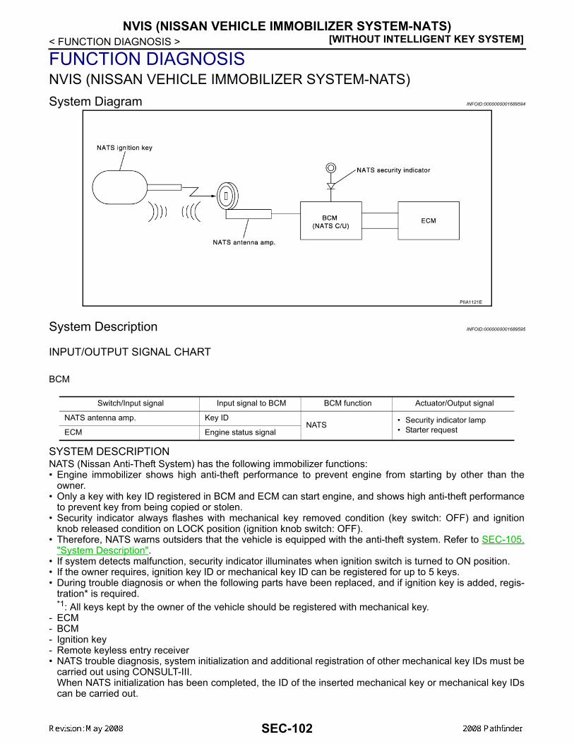
[WITHOUT INTELLIGENT KEY SYSTEM]NVIS (NISSAN VEHICLE IMMOBILIZER SYSTEM-NATS)
< FUNCTION DIAGNOSIS >
FUNCTION DIAGNOSISNVIS (NISSAN VEHICLE IMMOBILIZER SYSTEM-NATS)System Diagram INFOID:0000000001689594
System Description INFOID:0000000001689595
INPUT/OUTPUT SIGNAL CHART
BCM
SYSTEM DESCRIPTIONNATS (Nissan Anti-Theft System) has the following immobilizer functions:• Engine immobilizer shows high anti-theft performance to prevent engine from starting by other than the
owner.• Only a key with key ID registered in BCM and ECM can start engine, and shows high anti-theft performance
to prevent key from being copied or stolen.• Security indicator always flashes with mechanical key removed condition (key switch: OFF) and ignition
knob released condition on LOCK position (ignition knob switch: OFF). • Therefore, NATS warns outsiders that the vehicle is equipped with the anti-theft system. Refer to SEC-105,
"System Description".• If system detects malfunction, security indicator illuminates when ignition switch is turned to ON position.• If the owner requires, ignition key ID or mechanical key ID can be registered for up to 5 keys.• During trouble diagnosis or when the following parts have been replaced, and if ignition key is added, regis-
tration* is required. *1: All keys kept by the owner of the vehicle should be registered with mechanical key.
- ECM- BCM- Ignition key- Remote keyless entry receiver• NATS trouble diagnosis, system initialization and additional registration of other mechanical key IDs must be
carried out using CONSULT-III.When NATS initialization has been completed, the ID of the inserted mechanical key or mechanical key IDscan be carried out.
PIIA1121E
Switch/Input signal Input signal to BCM BCM function Actuator/Output signal
NATS antenna amp. Key IDNATS • Security indicator lamp
• Starter requestECM Engine status signal
SEC-102
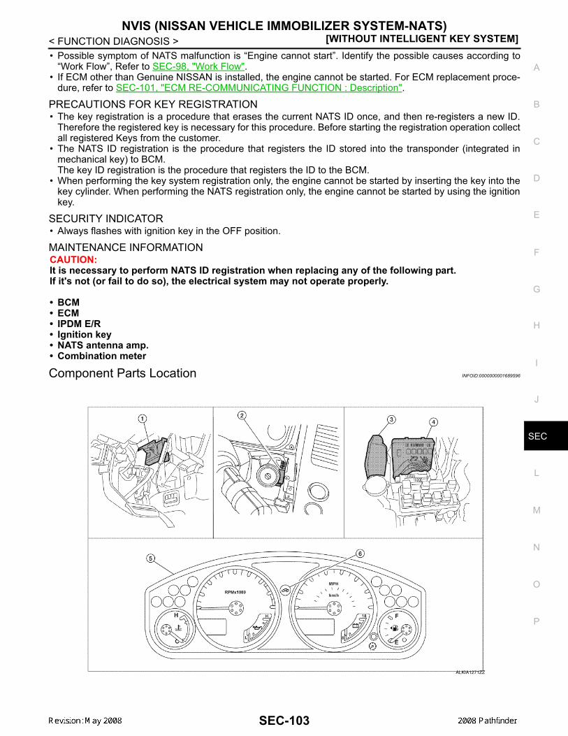
NVIS (NISSAN VEHICLE IMMOBILIZER SYSTEM-NATS)[WITHOUT INTELLIGENT KEY SYSTEM]
C
D
E
F
G
H
I
J
L
M
A
B
EC
N
O
P
< FUNCTION DIAGNOSIS >
S
• Possible symptom of NATS malfunction is “Engine cannot start”. Identify the possible causes according to“Work Flow”, Refer to SEC-98, "Work Flow".
• If ECM other than Genuine NISSAN is installed, the engine cannot be started. For ECM replacement proce-dure, refer to SEC-101, "ECM RE-COMMUNICATING FUNCTION : Description".
PRECAUTIONS FOR KEY REGISTRATION• The key registration is a procedure that erases the current NATS ID once, and then re-registers a new ID.
Therefore the registered key is necessary for this procedure. Before starting the registration operation collectall registered Keys from the customer.
• The NATS ID registration is the procedure that registers the ID stored into the transponder (integrated inmechanical key) to BCM.The key ID registration is the procedure that registers the ID to the BCM.
• When performing the key system registration only, the engine cannot be started by inserting the key into thekey cylinder. When performing the NATS registration only, the engine cannot be started by using the ignitionkey.
SECURITY INDICATOR• Always flashes with ignition key in the OFF position.
MAINTENANCE INFORMATIONCAUTION:It is necessary to perform NATS ID registration when replacing any of the following part.If it's not (or fail to do so), the electrical system may not operate properly.
• BCM• ECM• IPDM E/R• Ignition key• NATS antenna amp.• Combination meter
Component Parts Location INFOID:0000000001689596
ALKIA1271ZZ
SEC-103

[WITHOUT INTELLIGENT KEY SYSTEM]NVIS (NISSAN VEHICLE IMMOBILIZER SYSTEM-NATS)
< FUNCTION DIAGNOSIS >
Component Description INFOID:0000000001689597
1. BCM M18, M20(view with instrument panel LH re-moved)
2. NATS antenna amp. M21 3. ECM E16
4. IPDM E/R E119, E120, E122, E124(view with cover removed)
5. Combination meter M24 6. Security indicator lamp
Item Function
BCM Verifies the received signal from the ignition key ID, then informs ECM whether to allow engine start.
Remote keyless entry receiver Receives lock/unlock signal from the keyfob, and then transmits to the BCM.
A/T device (detention key switch) Detects whether the shift lever is in park.
NATS antenna amp. Detects the ignition key presence in the ignition key cylinder.
Security indicator Indicates the status of the security system.
IPDM E/R Powers-up the horn and the headlamps in case of a security breach.
SEC-104

VEHICLE SECURITY SYSTEM[WITHOUT INTELLIGENT KEY SYSTEM]
C
D
E
F
G
H
I
J
L
M
A
B
EC
N
O
P
< FUNCTION DIAGNOSIS >
S
VEHICLE SECURITY SYSTEMSystem Diagram INFOID:0000000001689598
System Description INFOID:0000000001689599
DESCRIPTIONThe security system provides an audible and visual alarm when an unauthorized access to the vehicle isdetected while the system is in armed phase.The security system consist of the BCM managing the audible alarm (horn) and the visual alarm (headlamps).
OPERATION FLOW
Disarmed PhaseWhen the vehicle is being driven or when doors are open, the theft warning system is set in the disarmedphase on the assumption that the owner is inside or near the vehicle.Pre-Armed Phase And Armed PhaseThe vehicle security system turns into the pre-armed phase when ignition switch is in OFF position, all doorsare closed and locked (using keyfob, doorlock/unlock switch, driver key cylinder or auto relock function). Thesystem automatically shifts into the armed phase.Condition of Activating The SystemWhen the following condition is performed in armed phase, the system sounds the horns and flashes theheadlamps for about 30 seconds.• Any door is opened.
ALKIA0706GB
PIIA1367E
SEC-105

[WITHOUT INTELLIGENT KEY SYSTEM]VEHICLE SECURITY SYSTEM
< FUNCTION DIAGNOSIS >Condition of Deactivating The SystemWhen one of the following operations is performed, the armed phase is canceled.• Unlock the doors with keyfob.• Use the mechanical key to unlock the driver door using the door key cylinder.
Component Parts Location INFOID:0000000001728844
1. BCM M18, M19, M20(view with instrument panel LH re-moved)
2. IPDM E/R E122, E123, E124(view with cover removed)
3. Horn relay H-1
4. Main power window and door lock/unlock switch D7, D8
5. Front door switch LH B8RH B108
6. Front door lock assembly LH (key cylin-der switch) D14
7. Power window and door lock/unlock switch RH D105
8. Rear door switch LH B18RH B116
9. Back door cinching latch unit (door ajar switch) D502Glass hatch ajar switch D503
10. Horn E3(behind front combination lamp LH)
11. Combination meter M24 12. Security indicator lamp
ALKIA1270ZZ
SEC-106

VEHICLE SECURITY SYSTEM[WITHOUT INTELLIGENT KEY SYSTEM]
C
D
E
F
G
H
I
J
L
M
A
B
EC
N
O
P
< FUNCTION DIAGNOSIS >
S
Component Description INFOID:0000000001689601
Item Function
BCM Verifies the received signal from ignition key, then informs ECM whether to allow engine start.
Door switch Provides the BCM with the status of each monitored door.
Security indicator Indicates the status of the security system.
IPDM E/R Controls the horn and headlamps operation.
Horn Sounds when the vehicle security system is triggered.
SEC-107

[WITHOUT INTELLIGENT KEY SYSTEM]DIAGNOSIS SYSTEM (BCM)
< FUNCTION DIAGNOSIS >DIAGNOSIS SYSTEM (BCM)COMMON ITEMCOMMON ITEM : CONSULT-III Function (BCM - COMMON ITEM) INFOID:0000000001689602
APPLICATION ITEMCONSULT-III performs the following functions via CAN communication with BCM.
SYSTEM APPLICATIONBCM can perform the following functions for each system.NOTE:It can perform the diagnosis modes except the following for all sub system selection items.
IMMUIMMU : CONSULT-III Function (BCM - IMMU) INFOID:0000000001689603
APPLICATION ITEMCONSULT-III performs the following functions via CAN communication with BCM.
DATA MONITOR
Diagnosis mode Function Description
WORK SUPPORT Changes the setting for each system function.
SELF-DIAG RESULTS Displays the diagnosis results judged by BCM. Refer to SEC-71, "DTC Index".
CAN DIAG SUPPORT MNTR Monitors the reception status of CAN communication viewed from BCM.
DATA MONITOR The BCM input/output signals are displayed.
ACTIVE TEST The signals used to activate each device are forcibly supplied from BCM.
ECU IDENTIFICATION The BCM part number is displayed.
CONFIGURATION • Enables to read and save the vehicle specification.• Enables to write the vehicle specification when replacing BCM.
System Sub system selection itemDiagnosis mode
WORK SUPPORT DATA MONITOR ACTIVE TEST
— BCM ×
Door lock DOOR LOCK × × ×
Rear window defogger REAR DEFOGGER × ×
Warning chime BUZZER × ×
Interior room lamp timer INT LAMP × × ×
Remote keyless entry system MULTI REMOTE ENT × × ×
Exterior lamp HEAD LAMP × × ×
Wiper and washer WIPER × × ×
Turn signal and hazard warning lamps FLASHER × ×
Air conditioner AIR CONDITONER ×
Combination switch COMB SW ×
Immobilizer IMMU × ×
Interior room lamp battery saver BATTERY SAVER × × ×
Vehicle security system THEFT ALM × × ×
Diagnosis mode Function Description
DATA MONITOR The BCM input/output signals are displayed.
ACTIVE TEST The signals used to activate each device are forcibly supplied from Intelligent Key unit.
SEC-108

DIAGNOSIS SYSTEM (BCM)[WITHOUT INTELLIGENT KEY SYSTEM]
C
D
E
F
G
H
I
J
L
M
A
B
EC
N
O
P
< FUNCTION DIAGNOSIS >
S
ACTIVE TEST
THEFT ALMTHEFT ALM : CONSULT-III Function (BCM - THEFT ALM) INFOID:0000000001689604
APPLICATION ITEMCONSULT-III performs the following functions via CAN communication with BCM.
DATA MONITOR
ACTIVE TEST
WORK SUPPORT
Monitor item Content
IGN ON SW Indicates [ON/OFF] condition of ignition switch in ON position.
KEY ON SW Indicates [ON/OFF] condition of key switch.
Test item Description
THEFT IND This test is able to check security indicator operation [ON/OFF].
Diagnosis mode Function Description
WORK SUPPORT Changes the setting for each system function.
DATA MONITOR The BCM input/output signals are displayed.
ACTIVE TEST The signals used to activate each device are forcibly supplied from BCM.
Monitor Item Condition
IGN ON SW Indicates [ON/OFF] condition of ignition switch in ON position.
ACC ON SW Indicates [ON/OFF] condition of ignition switch in ACC position.
PUSH SW Indicates [ON/OFF] condition of ignition knob switch.
KEY ON SW Indicates [ON/OFF] condition of key switch.
DOOR SW-DR Indicates [ON/OFF] condition of front door switch (driver side).
DOOR SW-AS Indicates [ON/OFF] condition of front door switch (passenger side).
DOOR SW-RR Indicates [ON/OFF] condition of rear door switch RH.
DOOR SW-RL Indicates [ON/OFF] condition of rear door switch LH.
BACK DOOR SW Indicates [ON/OFF] condition of back door switch.
CDL LOCK SW Indicates [ON/OFF] condition of door lock and unlock switch.
CDL UNLOCK SW Indicates [ON/OFF] condition of door lock and unlock switch.
Test item Description
THEFT IND This test is able to check security indicator operation [ON/OFF].
VEHICLE SECURITY HORN This test is able to check horn operation [ON].
FLASHER This test is able to check flasher operation [LH/RH/OFF].
Test item Description
SECURITY ALARM SETVehicle security function mode can be changed in this mode.• ON: Vehicle security function is ON.• OFF: Vehicle security function is OFF.
THEFT ALM TRG The switch which triggered vehicle security system is recorded. This mode can be able to con-firm and erase the record of vehicle security system.
SEC-109

[WITHOUT INTELLIGENT KEY SYSTEM]U1000 CAN COMM CIRCUIT
< COMPONENT DIAGNOSIS >
COMPONENT DIAGNOSISU1000 CAN COMM CIRCUITDescription INFOID:0000000001689605
CAN (Controller Area Network) is a serial communication line for real time applications. It is an on-vehicle mul-tiplex communication line with high data communication speed and excellent error detection ability. Modernvehicle is equipped with many electronic control unit, and each control unit shares information and links withother control units during operation (not independent). In CAN communication, control units are connectedwith 2 communication lines (CAN-H line, CAN-L line) allowing a high rate of information transmission with lesswiring. Each control unit transmits/receives data but selectively reads required data only.CAN Communication Signal Chart, refer to .LAN-57, "CAN Communication Signal Chart"
DTC Logic INFOID:0000000001689606
DTC DETECTION LOGIC
Diagnosis Procedure INFOID:0000000001689607
1.PERFORM SELF DIAGNOSTIC
1. Turn ignition switch ON and wait for 2 seconds or more.2. Check “Self Diagnostic Result”.Is “CAN COMM CIRCUIT” displayed?YES >> Refer to LAN-5, "CAN Communication Control Circuit".NO >> Refer to GI-51, "Intermittent Incident".
DTC CONSULT-III display description DTC Detection Condition Possible cause
U1000 CAN COMM CIRCUITWhen BCM cannot communicate CAN com-munication signal continuously for 2 sec-onds or more.
In CAN communication system, any item (or items) of the following listed below is malfunctioning.• Receiving (TCM)• Receiving (IPDM E/R)• Receiving (ECM)• Receiving (METER/M&A)• Receiving (MULTI AV)
SEC-110

U1010 CONTROL UNIT (CAN)[WITHOUT INTELLIGENT KEY SYSTEM]
C
D
E
F
G
H
I
J
L
M
A
B
EC
N
O
P
< COMPONENT DIAGNOSIS >
S
U1010 CONTROL UNIT (CAN)Description INFOID:0000000001689608
CAN (Controller Area Network) is a serial communication line for real time applications. It is an on-vehicle mul-tiplex communication line with high data communication speed and excellent error detection ability. Modernvehicle is equipped with many electronic control unit, and each control unit shares information and links withother control units during operation (not independent). In CAN communication, control units are connectedwith 2 communication lines (CAN-H line, CAN-L line) allowing a high rate of information transmission with lesswiring. Each control unit transmits/receives data but selectively reads required data only.CAN Communication Signal Chart, refer to LAN-57, "CAN Communication Signal Chart".
DTC Logic INFOID:0000000001689609
DTC DETECTION LOGIC
Diagnosis Procedure INFOID:0000000001689610
1.REPLACE BCM
When DTC [U1010] is detected, replace BCM.
>> Replace BCM. Refer to BCS-54, "Removal and Installation".
Special Repair Requirement INFOID:0000000001689611
1.REQUIRED WORK WHEN REPLACING BCM
Initialize BCM. Refer to CONSULT-III Operation Manual.
>> Work end.
DTC CONSULT-III display de-scription DTC Detection Condition Possible cause
U1010 CONTROL UNIT (CAN) When detecting error during the initial diagnosis of CAN control-ler of BCM. BCM
SEC-111
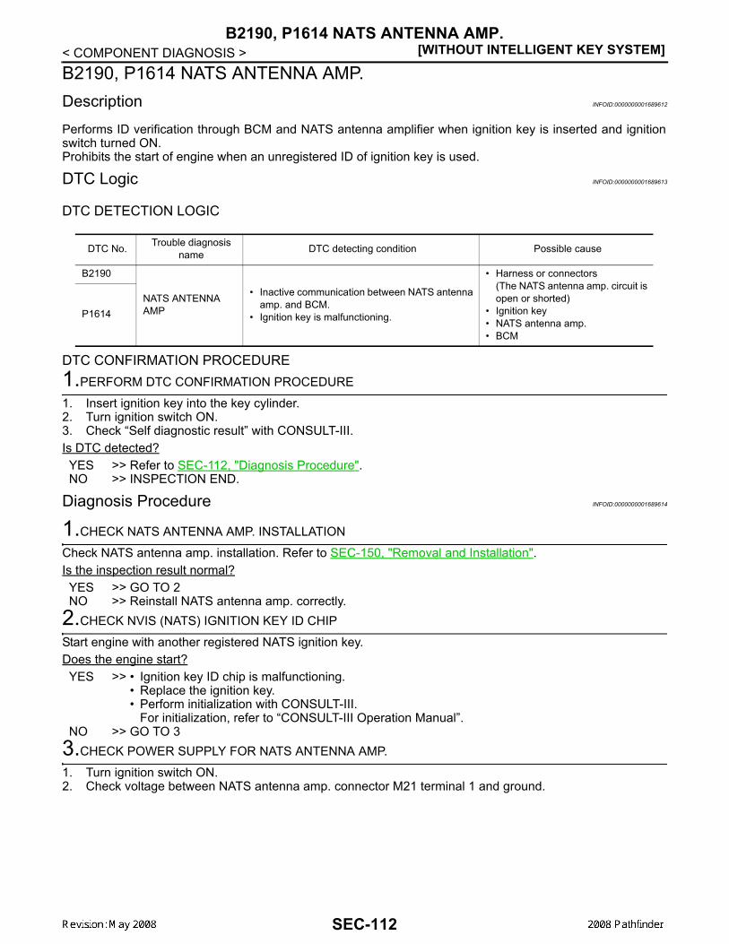
[WITHOUT INTELLIGENT KEY SYSTEM]B2190, P1614 NATS ANTENNA AMP.
< COMPONENT DIAGNOSIS >B2190, P1614 NATS ANTENNA AMP.Description INFOID:0000000001689612
Performs ID verification through BCM and NATS antenna amplifier when ignition key is inserted and ignitionswitch turned ON.Prohibits the start of engine when an unregistered ID of ignition key is used.
DTC Logic INFOID:0000000001689613
DTC DETECTION LOGIC
DTC CONFIRMATION PROCEDURE1.PERFORM DTC CONFIRMATION PROCEDURE
1. Insert ignition key into the key cylinder.2. Turn ignition switch ON.3. Check “Self diagnostic result” with CONSULT-III.Is DTC detected?YES >> Refer to SEC-112, "Diagnosis Procedure".NO >> INSPECTION END.
Diagnosis Procedure INFOID:0000000001689614
1.CHECK NATS ANTENNA AMP. INSTALLATION
Check NATS antenna amp. installation. Refer to SEC-150, "Removal and Installation".Is the inspection result normal?YES >> GO TO 2NO >> Reinstall NATS antenna amp. correctly.
2.CHECK NVIS (NATS) IGNITION KEY ID CHIP
Start engine with another registered NATS ignition key.Does the engine start?YES >> • Ignition key ID chip is malfunctioning.
• Replace the ignition key.• Perform initialization with CONSULT-III.
For initialization, refer to “CONSULT-III Operation Manual”.NO >> GO TO 3
3.CHECK POWER SUPPLY FOR NATS ANTENNA AMP.
1. Turn ignition switch ON.2. Check voltage between NATS antenna amp. connector M21 terminal 1 and ground.
DTC No. Trouble diagnosis name DTC detecting condition Possible cause
B2190
NATS ANTENNA AMP
• Inactive communication between NATS antenna amp. and BCM.
• Ignition key is malfunctioning.
• Harness or connectors(The NATS antenna amp. circuit is open or shorted)
• Ignition key• NATS antenna amp.• BCM
P1614
SEC-112

B2190, P1614 NATS ANTENNA AMP.[WITHOUT INTELLIGENT KEY SYSTEM]
C
D
E
F
G
H
I
J
L
M
A
B
EC
N
O
P
< COMPONENT DIAGNOSIS >
S
Is the inspection result normal?YES >> GO TO 4NO >> Repair or replace fuse or harness.
4.CHECK NATS ANTENNA AMP. GROUND LINE CIRCUIT
1. Turn ignition switch OFF.2. Disconnect NATS antenna amp. connector.3. Check continuity between NATS antenna amp. connector M21 terminal 3 and ground.
Is the inspection result normal?YES >> GO TO 5NO >> • Repair or replace harness.
NOTE:If harness is OK, replace BCM, perform initializationwith CONSULT-III. For initialization, refer to “CON-SULT-III Operation Manual”.
5.CHECK NATS ANTENNA AMP. SIGNAL LINE- 1
1. Connect NATS antenna amp. connector.2. Turn ignition switch ON.3. Check voltage between NATS antenna amp. connector M21 ter-
minal 2 and ground with analog tester.
Is the inspection result normal?YES >> GO TO 6NO >> • Repair or replace harness.
NOTE:If harness is OK, replace BCM, perform initialization with CONSULT-III. For initialization, refer to“CONSULT-III Operation Manual”.
1 - Ground : Battery voltage
LIIA1280E
3 - Ground : Continuity should exist.
LIIA1283E
LIIA1281E
TerminalsPosition of ignition key cylinder Voltage (V)
(Approx.)( + ) ( - )
2 Ground
Before inserting ignition key Battery voltage
After inserting ignition key Pointer of tester should move for approx. 30 seconds, then return to battery voltage
Just after turning ignition switch ON
Pointer of tester should move for approx. 1 second, then return to battery voltage
SEC-113

[WITHOUT INTELLIGENT KEY SYSTEM]B2190, P1614 NATS ANTENNA AMP.
< COMPONENT DIAGNOSIS >
6.CHECK NATS ANTENNA AMP. SIGNAL LINE- 2
Check voltage between NATS antenna amp. connector M21 terminal4 and ground with analog tester.
Is the inspection result normal?YES >> NATS antenna amp. is malfunctioning.NO >> • Repair or replace harness.
NOTE:If harness is OK, replace BCM, refer to XX-XX, "*****". Perform initialization with CONSULT-III.For initialization, refer to “CONSULT-III Operation Manual”.
LIIA1282E
TerminalsPosition of ignition key cylinder Voltage (V)
(Approx.)( + ) ( - )
4 Ground
Before inserting ignition key Battery voltage
After inserting ignition key Pointer of tester should move for approx. 30 seconds, then return to battery voltage
Just after turning ignition switch ON
Pointer of tester should move for approx. 1 second, then return to battery voltage
SEC-114

B2191, P1615 DIFFERENCE OF KEY[WITHOUT INTELLIGENT KEY SYSTEM]
C
D
E
F
G
H
I
J
L
M
A
B
EC
N
O
P
< COMPONENT DIAGNOSIS >
S
B2191, P1615 DIFFERENCE OF KEYDescription INFOID:0000000001689615
Performs ID verification through BCM when ignition knob switch is pressed.Prohibits the release of steering lock or start of engine when an unregistered ID of mechanical key is used.
DTC Logic INFOID:0000000001689616
DTC DETECTION LOGIC
DTC CONFIRMATION PROCEDURE1.PERFORM DTC CONFIRMATION PROCEDURE
1. Insert mechanical key into the key cylinder.2. Check “Self diagnostic result” with CONSULT-III.Is DTC detected?YES >> Refer toSEC-115, "Diagnosis Procedure".NO >> INSPECTION END.
Diagnosis Procedure INFOID:0000000001689617
1.PERFORM INITIALIZATION
Perform initialization with CONSULT-III. Re-register all mechanical keys.For initialization and registration of mechanical key. Refer to “CONSULT-III Operation Manual”.Can the system be initialized and can the engine be started with re-registered mechanical key?YES >> Mechanical key was unregistered.NO >> BCM is malfunctioning.
• Replace BCM. Refer to BCS-54, "Removal and Installation".• Perform initialization again
DTC No. Trouble diagnosis name DTC detecting condition Possible cause
B2191 DIFFERENCE OF KEY
The ID verification results between BCM and me-chanical key are NG. The registration is necessary. Mechanical key
P1615
SEC-115

[WITHOUT INTELLIGENT KEY SYSTEM]B2192, P1611 ID DISCORD, IMMU-ECM
< COMPONENT DIAGNOSIS >B2192, P1611 ID DISCORD, IMMU-ECMDescription INFOID:0000000001689618
BCM performs the ID verification with ECM that allows the engine to start. BCM starts the communication withECM if ignition switch is turned ON and starts the engine if the ID is OK. ECM prevents the engine from start-ing if the ID is not registered.
DTC Logic INFOID:0000000001689619
DTC DETECTION LOGICNOTE:• If DTC B2192 is displayed with DTC U1000, first perform the trouble diagnosis for DTC U1000. Refer to
SEC-110, "DTC Logic".• If DTC B2192 is displayed with DTC U1010, first perform the trouble diagnosis for DTC U1010. Refer to
SEC-111, "DTC Logic".
DTC CONFIRMATION PROCEDURE1.PERFORM DTC CONFIRMATION PROCEDURE
1. Turn ignition switch ON.2. Check “Self diagnostic result” with CONSULT-III.Is DTC detected?YES >> Refer to SEC-116, "Diagnosis Procedure".NO >> INSPECTION END.
Diagnosis Procedure INFOID:0000000001689620
1.PERFORM INITIALIZATION
Perform initialization with CONSULT-III. Re-register all mechanical keys.For initialization and registration of mechanical key. Refer to “CONSULT-III Operation Manual”.Can the system be initialized and can the engine be started with re-registered mechanical key?YES >> ID was unregistered.NO >> GO TO 2
2.PEPLACE BCM
1. Replace BCM. Refer to BCS-54, "Removal and Installation".2. Perform initialization with CONSULT-III. Re-register all mechanical keys.
For initialization and registration of mechanical key. Refer to “CONSULT-III Operation Manual”.Can the system be initialized and can the engine be started with re-registered mechanical key?YES >> BCM is malfunctioning.NO >> GO TO 3
3.PEPLACE ECM
1. Replace ECM. Refer to Removal and Installation.2. Perform initialization with CONSULT-III. Re-register all mechanical keys.
For initialization and registration of mechanical key. Refer to “CONSULT-III Operation Manual”.Can the system be initialized and can the engine be started with re-registered mechanical key?YES >> ECM is malfunctioning.NO >> GO TO 4
4.CHECK INTERMITENT INCIDENT
Refer to GI-51, "Intermittent Incident".
DTC No. Trouble diagnosis name DTC detecting condition Possible cause
B2192 ID DISCORD BCM-ECM
The ID verification results between BCM and ECM are NG. The registration is necessary.
• BCM• ECMP1611
SEC-116

B2192, P1611 ID DISCORD, IMMU-ECM[WITHOUT INTELLIGENT KEY SYSTEM]
C
D
E
F
G
H
I
J
L
M
A
B
EC
N
O
P
< COMPONENT DIAGNOSIS >
S
>> INSPECTION END
SEC-117

[WITHOUT INTELLIGENT KEY SYSTEM]B2193, P1612 CHAIN OF ECM-IMMU
< COMPONENT DIAGNOSIS >B2193, P1612 CHAIN OF ECM-IMMUDescription INFOID:0000000001689621
BCM performs the ID verification with ECM that allows the engine to start. BCM starts the communication withECM if ignition switch is turned ON and starts the engine if the ID is OK. ECM prevents the engine from start-ing if the ID is not registered.
DTC Logic INFOID:0000000001689622
DTC DETECTION LOGICNOTE:• If DTC B2193 is displayed with DTC U1000, first perform the trouble diagnosis for DTC U1000. Refer to
SEC-110, "DTC Logic".• If DTC B2193 is displayed with DTC U1010, first perform the trouble diagnosis for DTC U1010. Refer to
SEC-111, "DTC Logic".
DTC CONFIRMATION PROCEDURE1.PERFORM DTC CONFIRMATION PROCEDURE
1. Turn ignition switch ON.2. Check “Self diagnostic result” with CONSULT-III.Is DTC detected?YES >> Refer to SEC-118, "Diagnosis Procedure".NO >> INSPECTION END
Diagnosis Procedure INFOID:0000000001689623
1.REPLACE BCM
1. Replace BCM. Refer to BCS-54, "Removal and Installation".2. Perform initialization with CONSULT-III.
For initialization, refer to “CONSULT-III Operation Manual”.Does the engine start?YES >> BCM was malfunctioning.NO >> ECM is malfunctioning.
• Replace ECM.• Perform ECM re-communicating function.
DTC No. Trouble diagnosis name DTC detecting condition Possible cause
B2193
CHAIN OF BCM-ECM Inactive communication between ECM and BCM
• Harness or connectors(The CAN communication line is open or short)
• BCM• ECM
P1612
SEC-118

P1610 LOCK MODE[WITHOUT INTELLIGENT KEY SYSTEM]
C
D
E
F
G
H
I
J
L
M
A
B
EC
N
O
P
< COMPONENT DIAGNOSIS >
S
P1610 LOCK MODEDescription INFOID:0000000001689624
When the starting operation is carried more than five times consecutively under the following conditions, NATSwill shift to the mode which prevents the engine from being started.• Unregistered mechanical key is used.• BCM or ECM's malfunctioning.
DTC Logic INFOID:0000000001689625
DTC DETECTION LOGIC
DTC CONFIRMATION PROCEDURE1.PERFORM DTC CONFIRMATION PROCEDURE
1. Turn ignition switch ON.2. Check “Self diagnostic result” with CONSULT-III.Is DTC detected?YES >> Refer to SEC-119, "Diagnosis Procedure".NO >> INSPECTION END
Diagnosis Procedure INFOID:0000000001689626
1.CHECK ENGINE START FUNCTION
1. Perform the check for DTC except DTC P1610.2. Use CONSULT-III to erase DTC after fixing.3. Check that engine can start with registered mechanical key.Does the engine start?YES >> INSPECTION ENDNO >> GO TO 2
2.CHECK INTERMITTENT INCIDENT
Refer to GI-51, "Intermittent Incident".
>> INSPECTION END
DTC No. Trouble diagnosis name DTC detecting condition Possible cause
P1610 LOCK MODE
When the starting operation is carried out five or more times consecutively under the following conditions.• Unregistered mechanical key• BCM or ECM's malfunctioning.
—
SEC-119

[WITHOUT INTELLIGENT KEY SYSTEM]POWER SUPPLY AND GROUND CIRCUIT
< COMPONENT DIAGNOSIS >POWER SUPPLY AND GROUND CIRCUITBCMBCM : Diagnosis Procedure INFOID:0000000001689627
Refer to BCS-32, "Diagnosis Procedure".
SEC-120

KEY CYLINDER SWITCH[WITHOUT INTELLIGENT KEY SYSTEM]
C
D
E
F
G
H
I
J
L
M
A
B
EC
N
O
P
< COMPONENT DIAGNOSIS >
S
KEY CYLINDER SWITCHDescription INFOID:0000000001728845
The main power window and door lock/unlock switch detects condition of the door key cylinder switch andtransmits to BCM as the LOCK or UNLOCK signal.
Component Function Check INFOID:0000000001728846
1.CHECK DOOR KEY CYLINDER SWITCH INPUT SIGNAL
Check "KEY CYL LK-SW" AND "KEY CYL UN-SW" in DATA MONITOR mode for “POWER DOOR LOCKSYSTEM” with CONSULT-III.
Is the inspection result normal?YES >> Key cylinder switch is OK.NO >> Refer to SEC-121, "Diagnosis Procedure".
Diagnosis Procedure INFOID:0000000001728847
1.CHECK DOOR KEY CYLINDER SWITCH LH
With CONSULT-IIICheck front door lock assembly LH (key cylinder switch) ("KEY CYL LK-SW") and ("KEY CYL UN-SW) inDATA MONITOR mode with CONSULT–III.• When key inserted in left front key cylinder is turned to LOCK:
• When key inserted in left front key cylinder is turned to UNLOCK:
Without CONSULT-IIICheck voltage between main power window and door lock/unlockswitch connector D7 terminals 4, 6 and ground.
Is the inspection result normal?YES >> Key cylinder switch signal is OK.NO >> GO TO 2.
2.CHECK DOOR KEY CYLINDER SWITCH LH GROUND HARNESS
1. Turn ignition switch OFF.2. Disconnect front door lock assembly LH (key cylinder switch).
Monitor item Condition
KEY CYL LK-SWLock : ON
Neutral / Unlock : OFF
KEY CYL UN-SWUnlock : ON
Neutral / Lock : OFF
KEY CYL LK-SW : ON
KEY CYL UN-SW : ON
ConnectorTerminals
Condition of left front key cylinder Voltage (V)(Approx.)(+) (–)
D7
4
Ground
Neutral/Unlock 5
Lock 0
6 Neutral/Lock 5
Unlock 0LIIA0566E
SEC-121

[WITHOUT INTELLIGENT KEY SYSTEM]KEY CYLINDER SWITCH
< COMPONENT DIAGNOSIS >3. Check continuity between front door lock assembly LH (key cyl-
inder switch) connector (A) D14 terminal 4 and body ground.
Is the inspection result normal?YES >> GO TO 3.NO >> Repair or replace harness.
3.CHECK DOOR KEY CYLINDER SWITCH LH
Check continuity between front door lock assembly LH (key cylinderswitch) terminals.
Is the inspection result normal?YES >> GO TO 4.NO >> Replace front door lock assembly LH (key cylinder switch). Refer to DLK-313, "Removal and
Installation".4.CHECK DOOR KEY CYLINDER HARNESS
Check continuity between main power window and door lock/unlockswitch connector (A) D7 terminals 4, 6 and front door lock assemblyLH (key cylinder switch) connector (B) D14 terminals 3, 5 and bodyground.
Is the inspection result normal?YES >> Replace main power window and door lock/unlock switch.NO >> Repair or replace harness.
Connector Terminals Continuity
D14 4 – Ground Yes
ALKIA1186ZZ
Terminals Condition Continuity
3 – 4Key is turned to LOCK or neutral. No
Key is turned to UNLOCK. Yes
4 – 5Key is turned to UNLOCK or neutral. No
Key is turned to LOCK. Yes
ALKIA1183ZZ
Connector Terminals Connector Terminals Continuity
A: Main power win-dow and door lock/
unlock switch
4 B: Front door lock assembly LH (key cylinder switch)
5 Yes
6 3 Yes
4, 6 Ground No
ALKIA1184ZZ
SEC-122
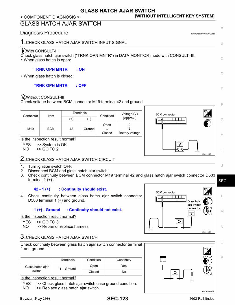
GLASS HATCH AJAR SWITCH[WITHOUT INTELLIGENT KEY SYSTEM]
C
D
E
F
G
H
I
J
L
M
A
B
EC
N
O
P
< COMPONENT DIAGNOSIS >
S
GLASS HATCH AJAR SWITCHDiagnosis Procedure INFOID:0000000001733166
1.CHECK GLASS HATCH AJAR SWITCH INPUT SIGNAL
With CONSULT-IIICheck glass hatch ajar switch ("TRNK OPN MNTR") in DATA MONITOR mode with CONSULT–III.• When glass hatch is open:
• When glass hatch is closed:
Without CONSULT-IIICheck voltage between BCM connector M19 terminal 42 and ground.
Is the inspection result normal?YES >> System is OK.NO >> GO TO 2
2.CHECK GLASS HATCH AJAR SWITCH CIRCUIT
1. Turn ignition switch OFF.2. Disconnect BCM and glass hatch ajar switch.3. Check continuity between BCM connector M19 terminal 42 and glass hatch ajar switch connector D503
terminal 1 (+) .
4. Check continuity between glass hatch ajar switch connectorD503 terminal 1 (+) and ground.
Is the inspection result normal?YES >> GO TO 3NO >> Repair or replace harness.
3.CHECK GLASS HATCH AJAR SWITCH
Check continuity between glass hatch ajar switch connector terminal1 and ground.
Is the inspection result normal?YES >> Check glass hatch ajar switch case ground condition.NO >> Replace glass hatch ajar switch.
TRNK OPN MNTR : ON
TRNK OPN MNTR : OFF
Connector ItemTerminals
Condition Voltage (V)(Approx.)(+) (–)
M19 BCM 42 GroundOpen↓
Closed
0↓
Battery voltage
LIIA1149E
42 - 1 (+) : Continuity should exist.
1 (+) - Ground : Continuity should not exist.
LIIA1150E
Terminals Condition Continuity
Glass hatch ajar switch 1 – Ground
Open Yes
Closed No
ALKIA0668ZZ
SEC-123

[WITHOUT INTELLIGENT KEY SYSTEM]HORN FUNCTION
< COMPONENT DIAGNOSIS >HORN FUNCTIONSymptom Table INFOID:0000000001689631
HAZARD AND HORN REMINDER FUNCTION MALFUNCTIONNOTE:• Before performing the diagnosis in the following table, check “Work flow”. Refer to SEC-98, "Work Flow".• If the following symptoms” are detected, check systems shown in the “Diagnosis/service procedure” column
in this order.Conditions of Vehicle (Operating Conditions)• “ANSWER BACK FUNCTION” is ON when setting on CONSULT-III.• Ignition switch is in OFF position.• All doors are closed.
Symptom Diagnosis/service procedure Reference page
Hazard reminder does not operate by key fob.(Horn reminder operate.)
1. Check “HAZARD ANSWER BACK” setting in “WORK SUPPORT”. SEC-108
2. Check hazard function. EXL-4
3. Check key fob battery inspection. DLK-234
Horn reminder does not operate by key fob.(Hazard reminder operate.)
1. Check “HORN WITH KEYLESS LOCK” setting in “WORK SUPPORT”. SEC-108
2. Check horn function. HRN-3
3. Check Intermittent Incident. GI-51
SEC-124

VEHICLE SECURITY INDICATOR[WITHOUT INTELLIGENT KEY SYSTEM]
C
D
E
F
G
H
I
J
L
M
A
B
EC
N
O
P
< COMPONENT DIAGNOSIS >
S
VEHICLE SECURITY INDICATORDescription INFOID:0000000001728848
• Vehicle security indicator is built in combination meter.• NATS (Nissan Anti-Theft System) and vehicle security system conditions are indicated by blink or illumina-
tion of vehicle security indicator.
Component Function Check INFOID:0000000001728849
1.CHECK FUNCTION
1. Perform “THEFT IND” in the “Active Test” mode with CONSULT-III.2. Check vehicle security indicator operation.
Is the inspection result normal?YES >> INSPECTION END.NO >> Refer to SEC-125, "Diagnosis Procedure".
Diagnosis Procedure INFOID:0000000001728850
1.SECURITY INDICATOR LAMP ACTIVE TEST
With CONSULT-IIICheck "THEFT IND” in "ACTIVE TEST" mode with CONSULT-III.
Without CONSULT-III1. Disconnect BCM.2. Check voltage between BCM harness connector M18 terminal
23 and ground.
Is the inspection result normal?YES >> Security indicator lamp is OK.NO >> GO TO 2
2.SECURITY INDICATOR LAMP CHECK
Check security indicator lamp condition.Is the inspection result normal?YES >> GO TO 3NO >> Replace security indicator lamp.
3.CHECK HARNESS CONTINUITY
1. Turn ignition switch OFF.2. Disconnect BCM and security indicator lamp connector.
Test item Description
THEFT INDON
Vehicle security indicatorON
OFF OFF
ConnectorTerminals
Condition Voltage (V)(Approx.)(+) (-)
M18 23 GroundON 0
OFF Battery voltage
LIIA0523E
SEC-125

[WITHOUT INTELLIGENT KEY SYSTEM]VEHICLE SECURITY INDICATOR
< COMPONENT DIAGNOSIS >3. Check continuity between BCM connector (A) M18 terminal 23
and combination meter connector (B) M24 terminal 39.
4. Check continuity between BCM connector (A) M18 terminal 23and ground.
Is the inspection result normal?YES >> Check the following:
• 10A fuse [No. 19, located in fuse block (J/B)]• Harness for open or short between security indicator lamp and fuse
NO >> Repair or replace harness.
23 - 39 : Continuity should exist.
23 - Ground : Continuity should not exist.
ALKIA1273ZZ
SEC-126

BCM (BODY CONTROL MODULE)[WITHOUT INTELLIGENT KEY SYSTEM]
C
D
E
F
G
H
I
J
L
M
A
B
EC
N
O
P
< ECU DIAGNOSIS >
S
ECU DIAGNOSISBCM (BODY CONTROL MODULE)Reference Value INFOID:0000000001689635
VALUES ON THE DIAGNOSIS TOOLRefer to BCS-38, "Reference Value".
TERMINAL LAYOUTRefer to BCS-41, "Terminal Layout".
PHYSICAL VALUESRefer to BCS-41, "Physical Values".
SEC-127

[WITHOUT INTELLIGENT KEY SYSTEM]BCM (BODY CONTROL MODULE)
< ECU DIAGNOSIS >Wiring Diagram - VEHICLE SECURITY SYSTEM INFOID:0000000001728851
AWKWA0067G
SEC-128

BCM (BODY CONTROL MODULE)[WITHOUT INTELLIGENT KEY SYSTEM]
C
D
E
F
G
H
I
J
L
M
A
B
EC
N
O
P
< ECU DIAGNOSIS >
S
AWKWA0068G
SEC-129

[WITHOUT INTELLIGENT KEY SYSTEM]BCM (BODY CONTROL MODULE)
< ECU DIAGNOSIS >
AWKIA0262GB
SEC-130

BCM (BODY CONTROL MODULE)[WITHOUT INTELLIGENT KEY SYSTEM]
C
D
E
F
G
H
I
J
L
M
A
B
EC
N
O
P
< ECU DIAGNOSIS >
S
AWKIA0263GB
SEC-131

[WITHOUT INTELLIGENT KEY SYSTEM]BCM (BODY CONTROL MODULE)
< ECU DIAGNOSIS >
AWKIA0264GB
SEC-132

BCM (BODY CONTROL MODULE)[WITHOUT INTELLIGENT KEY SYSTEM]
C
D
E
F
G
H
I
J
L
M
A
B
EC
N
O
P
< ECU DIAGNOSIS >
S
AWKIA0265GB
SEC-133
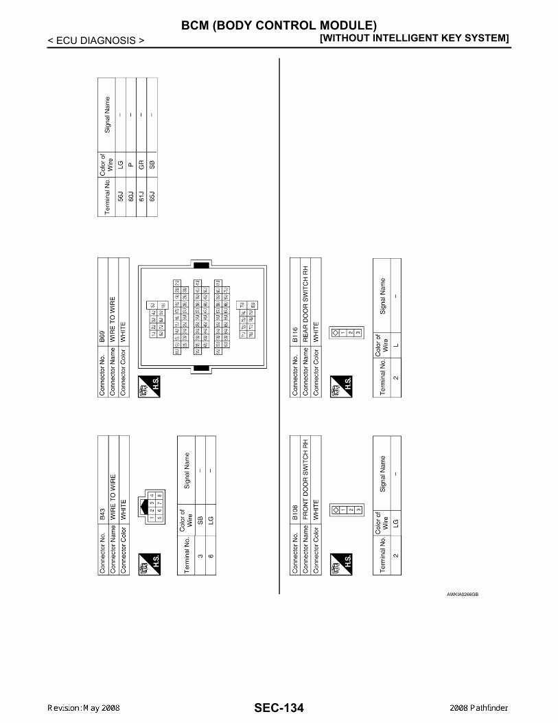
[WITHOUT INTELLIGENT KEY SYSTEM]BCM (BODY CONTROL MODULE)
< ECU DIAGNOSIS >
AWKIA0266GB
SEC-134

BCM (BODY CONTROL MODULE)[WITHOUT INTELLIGENT KEY SYSTEM]
C
D
E
F
G
H
I
J
L
M
A
B
EC
N
O
P
< ECU DIAGNOSIS >
S
AWKIA0267GB
SEC-135

[WITHOUT INTELLIGENT KEY SYSTEM]BCM (BODY CONTROL MODULE)
< ECU DIAGNOSIS >
AWKIA0268GB
SEC-136

BCM (BODY CONTROL MODULE)[WITHOUT INTELLIGENT KEY SYSTEM]
C
D
E
F
G
H
I
J
L
M
A
B
EC
N
O
P
< ECU DIAGNOSIS >
S
AWKIA0269GB
SEC-137

[WITHOUT INTELLIGENT KEY SYSTEM]BCM (BODY CONTROL MODULE)
< ECU DIAGNOSIS >Wiring Diagram - NVIS - INFOID:0000000001689637
AWKWA0062G
SEC-138

BCM (BODY CONTROL MODULE)[WITHOUT INTELLIGENT KEY SYSTEM]
C
D
E
F
G
H
I
J
L
M
A
B
EC
N
O
P
< ECU DIAGNOSIS >
S
AWKWA0063G
SEC-139

[WITHOUT INTELLIGENT KEY SYSTEM]BCM (BODY CONTROL MODULE)
< ECU DIAGNOSIS >
AWKIA0251GB
SEC-140

BCM (BODY CONTROL MODULE)[WITHOUT INTELLIGENT KEY SYSTEM]
C
D
E
F
G
H
I
J
L
M
A
B
EC
N
O
P
< ECU DIAGNOSIS >
S
AWKIA0252GB
SEC-141

[WITHOUT INTELLIGENT KEY SYSTEM]BCM (BODY CONTROL MODULE)
< ECU DIAGNOSIS >
AWKIA0253GB
SEC-142

BCM (BODY CONTROL MODULE)[WITHOUT INTELLIGENT KEY SYSTEM]
C
D
E
F
G
H
I
J
L
M
A
B
EC
N
O
P
< ECU DIAGNOSIS >
S
AWKIA0254GB
SEC-143

[WITHOUT INTELLIGENT KEY SYSTEM]BCM (BODY CONTROL MODULE)
< ECU DIAGNOSIS >
AWKIA0255GB
SEC-144

BCM (BODY CONTROL MODULE)[WITHOUT INTELLIGENT KEY SYSTEM]
C
D
E
F
G
H
I
J
L
M
A
B
EC
N
O
P
< ECU DIAGNOSIS >
S
DTC Inspection Priority Chart INFOID:0000000001689639
DTC Index INFOID:0000000001689640
NOTE:Details of time display
• CRNT: Displays when there is a malfunction now or after returning to the normal condition until turning igni-tion switch OFF → ON again.
• PAST: Displays when there is a malfunction that is detected in the past and stored.• 1 - 39: Displayed if any previous malfunction is present when current condition is normal. It increases like 1→ 2 → 3...38 → 39 after returning to the normal condition whenever ignition switch OFF → ON. The counterremains at 39 even if the number of cycles exceeds it. It is counted from 1 again when turning ignition switchOFF → ON after returning to the normal condition if the malfunction is detected again.
Priority DTC
1 • U1000: CAN COMM CIRCUIT• U1010: CONTROL UNIT (CAN)
2
• B2190: NATS ANTENNA AMP• B2191: DIFFERNCE OF KEY• B2192: ID DISCORD BCM-ECM• B2193: CHAIN OF BCM-ECM
CONSULT display TIME Fail-safe Refer to
No DTC is detected.further testingmay be required.
— — — —
U1000: CAN COMM CIRCUIT 0 1 - 39 — SEC-110
U1010: CONTROL UNIT (CAN) 0 1 - 39 — SEC-111
B2190: NATS ANTENNA AMP CRNT PAST × SEC-112
B2191: DIFFERENCE OF KEY CRNT PAST × SEC-115
B2192: ID DISCORD BCM-ECM CRNT PAST × SEC-116
B2193: CHAIN OF BCM-ECM CRNT PAST × SEC-118
SEC-145

[WITHOUT INTELLIGENT KEY SYSTEM]IPDM E/R (INTELLIGENT POWER DISTRIBUTION MODULE ENGINE ROOM)
< ECU DIAGNOSIS >IPDM E/R (INTELLIGENT POWER DISTRIBUTION MODULE ENGINEROOM)Reference Value INFOID:0000000001689641
VALUES ON THE DIAGNOSIS TOOLRefer to PCS-17, "Reference Value".
TERMINAL LAYOUTRefer to PCS-19, "Terminal Layout".
Fail Safe INFOID:0000000001689642
Refer to PCS-26, "Fail Safe".
DTC Index INFOID:0000000001689643
Refer to PCS-28, "DTC Index".
SEC-146

VEHICLE SECURITY SYSTEM SYMPTOMS[WITHOUT INTELLIGENT KEY SYSTEM]
C
D
E
F
G
H
I
J
L
M
A
B
EC
N
O
P
< SYMPTOM DIAGNOSIS >
S
SYMPTOM DIAGNOSISVEHICLE SECURITY SYSTEM SYMPTOMSSymptom Table INFOID:0000000001689644
*: Check the system is in the armed phase.
ProcedureDiagnostic procedure Refer to page
Symptom
1
Vehicle security sys-tem cannot be set by ····
Door switch Check door switch (LF, RF, LR, RR, back) DLK-214
Glass ajar switch Check glass hatch ajar switch SEC-123
Key cylinder switch Check key cylinder switch DLK-221
— Check Intermittent Incident GI-51
Security indicator does not turn ON.Check vehicle security indicator SEC-125
Check Intermittent Incident GI-51
2* Vehicle security system does not sound alarm when ····
Any door is opened. Check door switch (LF, RF, LR, RR, back) DLK-214
Glass ajar switch Check glass hatch ajar switch SEC-123
— Check Intermittent Incident GI-51
3Vehicle security alarm does not acti-vate.
Horn alarmCheck horn switch HRN-3
Check Intermittent Incident GI-51
4Vehicle security sys-tem cannot be can-celed by ····
Key cylinder switchCheck key cylinder switch SEC-121
Check Intermittent Incident GI-51
SEC-147

[WITHOUT INTELLIGENT KEY SYSTEM]NISSAN VEHICLE IMMOBILIZER SYSTEM-NATS SYMPTOMS
< SYMPTOM DIAGNOSIS >NISSAN VEHICLE IMMOBILIZER SYSTEM-NATS SYMPTOMSSymptom Table INFOID:0000000001689645
NOTE:• Before performing the diagnosis in the following table, check “SEC-98, "Work Flow"”. • Check that vehicle is under the condition shown in “Conditions of vehicle” before starting diagnosis, and
check each symptom.• If the following symptoms are detected, check systems shown in the “Diagnosis/service procedure” column
in this order.
CONDITIONS OF VEHICLE (OPERATING CONDITIONS)• Mechanical key is not inserted into key cylinder.• Ignition knob switch is not depressed.
Symptom Diagnosis/service procedure Reference page
Security indicator does not turn ON or flash.1. Check vehicle security indicator SEC-125
2. Check Intermittent Incident GI-51
SEC-148

PRE-INSPECTION FOR DIAGNOSTIC[WITHOUT INTELLIGENT KEY SYSTEM]
C
D
E
F
G
H
I
J
L
M
A
B
EC
N
O
P
< ON-VEHICLE MAINTENANCE >
S
ON-VEHICLE MAINTENANCEPRE-INSPECTION FOR DIAGNOSTICBasic Inspection INFOID:0000000001689646
1.INSPECTION START
Turn ignition switch “OFF”.NOTE:Before starting operation check, open front windows.
>> GO TO 2.2.CHECK SECURITY INDICATOR LAMP
1. Lock doors using keyfob or mechanical key.2. Check that security indicator lamp illuminates for 30 seconds.Does the security indicator lamp illuminate?YES >> GO TO 3.NO >> Perform diagnosis and repair. Refer to SEC-105, "System Description".
3.CHECK ALARM FUNCTION
1. After 30 seconds, security indicator lamp will start to blink.2. Open any door before unlocking with keyfob or mechanical key, or open back door or glass hatch without
keyfob.Does the alarm function properly?YES >> GO TO 4.NO >> Check the following.
• The vehicle security system does not phase in alarm mode. Refer to SEC-147, "SymptomTable".
• Alarm (horn and headlamps) does not operate. Refer to SEC-147, "Symptom Table".4.CHECK ALARM CANCEL OPERATION
Unlock any door using keyfob or mechanical key.Alarm (horn and headlamps) should stop.OK >> INSPECTION END.NG >> Check door lock function. Refer to DLK-199, "DOOR LOCK AND UNLOCK SWITCH : System
Description".
SEC-149

[WITHOUT INTELLIGENT KEY SYSTEM]VEHICLE SECURITY SYSTEM
< ON-VEHICLE REPAIR >
ON-VEHICLE REPAIRVEHICLE SECURITY SYSTEMRemoval and Installation INFOID:0000000001689647
REMOTE KEYLESS ENTRY RECEIVERRemoval1. Remove the instrument panel. Refer to IP-10, "Removal and Installation".2. Disconnect the wire harness (1), remove the bolt (A), and the
RKE receiver (2).
InstallationInstallation is in the reverse order of removal.
NATS ANTENNA AMPNOTE:• If NATS antenna amp. is not installed correctly, NVIS (NATS) system will not operate properly and "SELF-
DIAG RESULTS" on CONSULT -III screen will show "LOCK MODE" or "CHAIN OF IMMU-KEY"• Initilization is not necessary when only the NATS antenna amp. is replaced with a new one.Removal1. Disconnect the battery negative terminal.2. Remove the steering column covers. Refer to IP-10, "Exploded View".3. Remove the bolt, disconnect the electrical connector, and
remove the NATS antenna amp.
InstallationInstallation is in the reverse order of removal.
ALKIA0537ZZ
SIIA1683E
SEC-150

NATS ANTENNA AMP.[WITHOUT INTELLIGENT KEY SYSTEM]
C
D
E
F
G
H
I
J
L
M
A
B
EC
N
O
P
< REMOVAL AND INSTALLATION >
S
REMOVAL AND INSTALLATIONNATS ANTENNA AMP.Removal and Installation INFOID:0000000001683794
NOTE:• If NATS antenna amp. is not installed correctly, NVIS (NATS) system will not operate properly and "SELF-
DIAG RESULTS' on CONSULT-III screen will show "LOCK MODE" or "CHAIN OF IMMU-KEY'.• Initilization is not necessary when only the NATS antenna amp. is replaced with a new one.
REMOVAL1. Disconnect the battery negative terminal.2. Remove cluster lid A. Refer to IP-10, "Exploded View".3. Remove the bolt, disconnect the electrical connector, and remove the NATS antenna amp.
INSTALLATIONInstallation is in the reverse order of removal.
SEC-151

[WITHOUT INTELLIGENT KEY SYSTEM]REMOTE KEYLESS ENTRY RECEIVER
< REMOVAL AND INSTALLATION >REMOTE KEYLESS ENTRY RECEIVERRemoval INFOID:0000000001730846
1. Disconnect the battery negative cable.2. Remove the upper glove box. Refer to IP-10, "Exploded View".3. Remove the bolt, disconnect and remove the remote keyless entry receiver.
Installation INFOID:0000000001730847
Installation is in the reverse order of removal.
SEC-152
Related Documents