Design and Operation Self-study program M002 Boat Engines from Volkswagen Marine TDI 225-6

Welcome message from author
This document is posted to help you gain knowledge. Please leave a comment to let me know what you think about it! Share it to your friends and learn new things together.
Transcript

Self-study program M002
© 2006 Volkswagen Marine
The texts, illustrations and standards in this Owner's Manual are based on theinformation available at the time of going to print. Reproduction, duplication andtranslation, in whole or in part, only with the express written permission of VolkswagenMarine. All copyrights and patent rights are expressly reserved by Volkswagen Marine.Subject to alterations.
Postfach 31 11 76, 38231 SalzgitterEdition 08/06 print number 065.991.T06.20
❀ This paper was produced from woodpulp bleached without chlorine.
Design and Operation
Self-study program M002B
oa
t En
gin
es f
rom
V
olk
swa
gen
Ma
rine
TDI 225-6Copy date 08/06
WarningNote
The self-study program
is not a workshop manual!
Therefore, please take any adjustment and repair
instructions from the customer service literature
provided for this purpose.
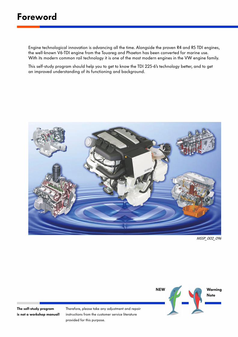
Engine technological innovation is advancing all the time. Alongside the proven R4 and R5 TDI engines, the well-known V6-TDI engine from the Touareg and Phaeton has been converted for marine use. With its modern common rail technology it is one of the most modern engines in the VW engine family.
This self-study program should help you to get to know the TDI 225-6’s technology better, and to get an improved understanding of its functioning and background.
Foreword
NEW
MSSP_002_096
3Superior Technology
Introduction . . . . . . . . . . . . . . . . . . . . . . . . . . . . . . . . . . 4
Engine mechanics . . . . . . . . . . . . . . . . . . . . . . . . . . . . . .8
Engine lubrication . . . . . . . . . . . . . . . . . . . . . . . . . . . . 16
Fuel injection system . . . . . . . . . . . . . . . . . . . . . . . . . 20
Engine electronics . . . . . . . . . . . . . . . . . . . . . . . . . . . . 30
Cooling system . . . . . . . . . . . . . . . . . . . . . . . . . . . . . . .42
Exhaust gas turbocharging . . . . . . . . . . . . . . . . . . . . .46
Electrical system . . . . . . . . . . . . . . . . . . . . . . . . . . . . . .48
Service . . . . . . . . . . . . . . . . . . . . . . . . . . . . . . . . . . . . . .50
Glossary . . . . . . . . . . . . . . . . . . . . . . . . . . . . . . . . . . . . 51
Contents

4Superior Technology
The TDI 225-6 engine
Description
The TDI 225-6 engine originates from the modern diesel engine series of the Volkswagen concern and has a V-type design.
The engine is fitted in the executive class vehicles, the Phaeton, Touareg, Audi A8, Audi A6 and Audi A4.
It is characterized by its extremely short and compact construction. Moreover, it successfully combines high performance with generous torque and smooth running.
The common-rail fuel injection system permits injection pressures of up to 1600 bar, while the injectors with their piezoelectric crystals enable precise control of the injected fuel quantity.
Thus, the V6-TDI engine fulfils the current EU exhaust gas standards (EC 2003/44 and BSO II).
Introduction
MSSP_002_001
5Superior Technology
Introduction
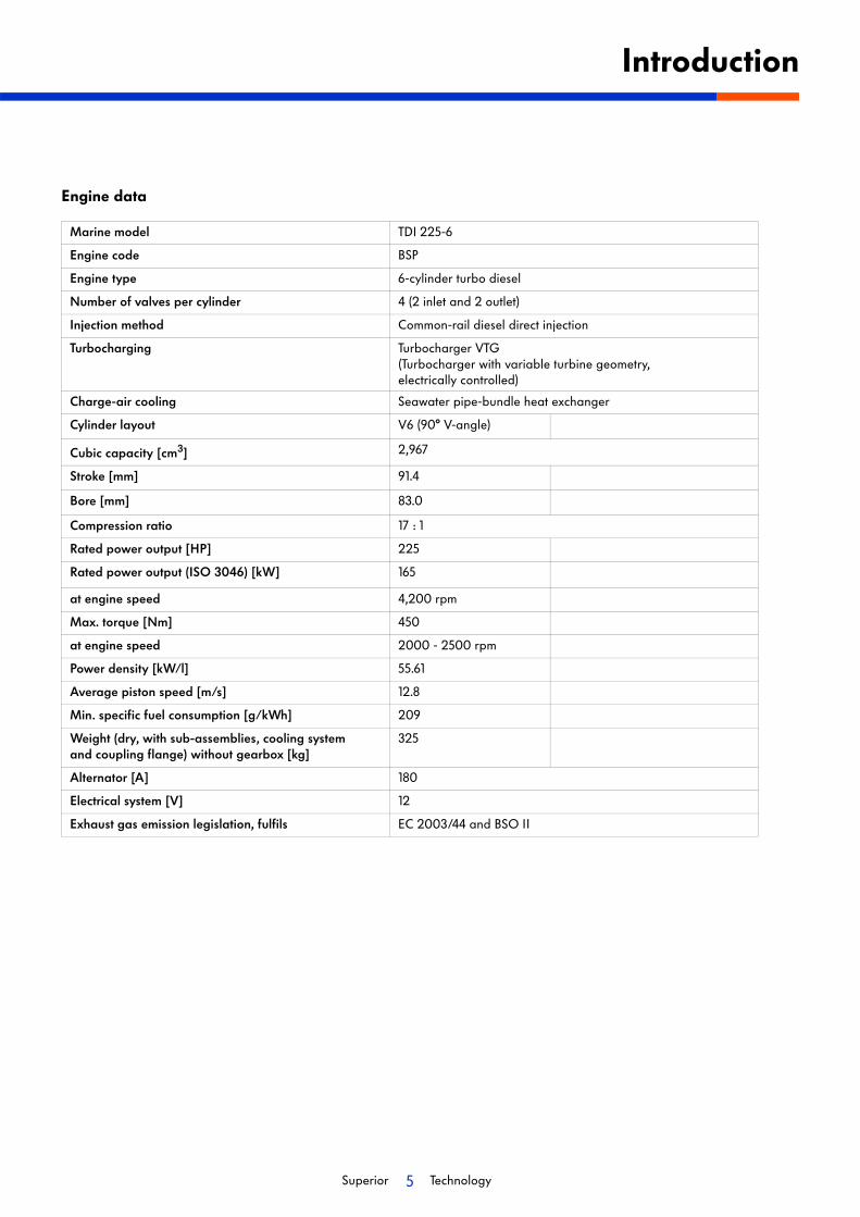
Engine data
Marine model TDI 225-6
Engine code BSP
Engine type 6-cylinder turbo diesel
Number of valves per cylinder 4 (2 inlet and 2 outlet)
Injection method Common-rail diesel direct injection
Turbocharging Turbocharger VTG (Turbocharger with variable turbine geometry, electrically controlled)
Charge-air cooling Seawater pipe-bundle heat exchanger
Cylinder layout V6 (90° V-angle)
Cubic capacity [cm3] 2,967
Stroke [mm] 91.4
Bore [mm] 83.0
Compression ratio 17 : 1
Rated power output [HP] 225
Rated power output (ISO 3046) [kW] 165
at engine speed 4,200 rpm
Max. torque [Nm] 450
at engine speed 2000 - 2500 rpm
Power density [kW/l] 55.61
Average piston speed [m/s] 12.8
Min. specific fuel consumption [g/kWh] 209
Weight (dry, with sub-assemblies, cooling system and coupling flange) without gearbox [kg]
325
Alternator [A] 180
Electrical system [V] 12
Exhaust gas emission legislation, fulfils EC 2003/44 and BSO II
6Superior Technology
Introduction
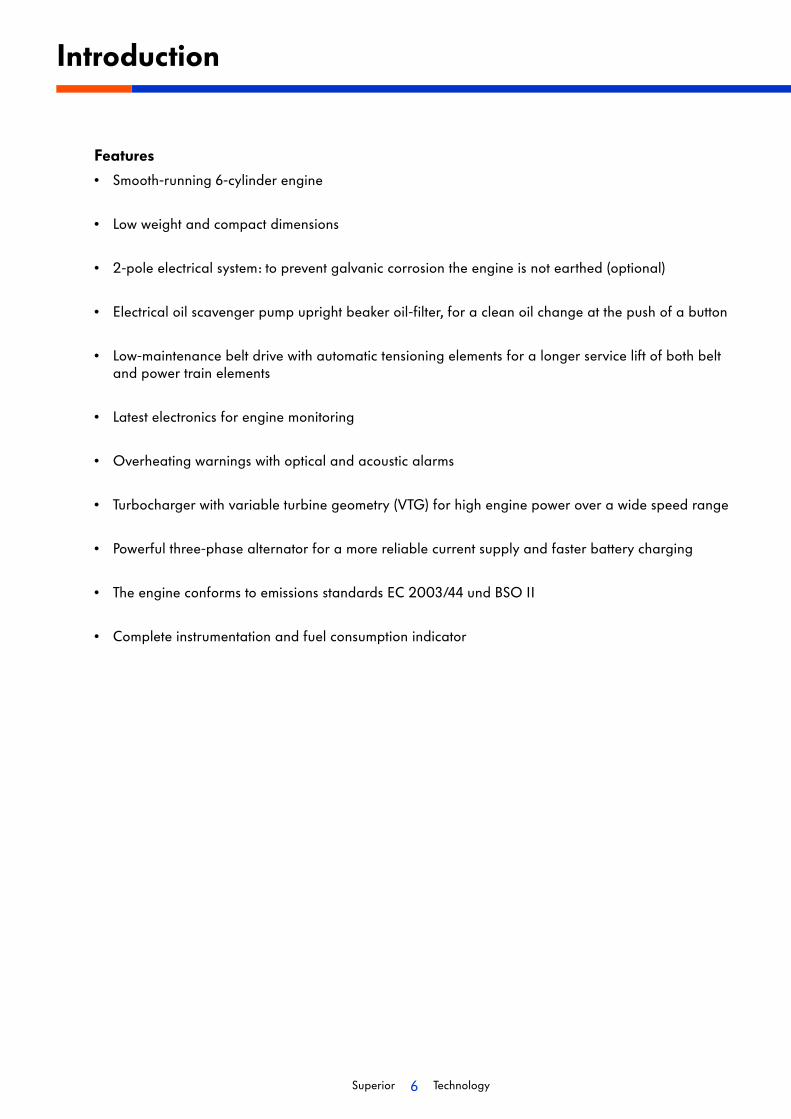
Features
• Smooth-running 6-cylinder engine
• Low weight and compact dimensions
• 2-pole electrical system: to prevent galvanic corrosion the engine is not earthed (optional)
• Electrical oil scavenger pump upright beaker oil-filter, for a clean oil change at the push of a button
• Low-maintenance belt drive with automatic tensioning elements for a longer service lift of both belt and power train elements
• Latest electronics for engine monitoring
• Overheating warnings with optical and acoustic alarms
• Turbocharger with variable turbine geometry (VTG) for high engine power over a wide speed range
• Powerful three-phase alternator for a more reliable current supply and faster battery charging
• The engine conforms to emissions standards EC 2003/44 und BSO II
• Complete instrumentation and fuel consumption indicator

7Superior Technology
Introduction
Volkswagen Marine boat motors have a
• MDC (Marine Diesel Control ) that is specially matched to boat operation, and is characterized by the highest reliability. An emergency running program with regeneration functions provides for very safe engine running should, in contrast to expectations, a malfunction occur.
• a wide useful speed range with high engine power.
• comprehensive corrosion protection for the engine housing and all its attached parts.
• a dual-weighted flywheel for absorption of drive and gearbox vibrations.
MSSP_002_002
Pow
er [
kW]
Torq
ue [
Nm
]
Speed [rpm]
Power
Torque

8Superior Technology
Cylinder head
As a V-engine, with a V-angle of 90°, the TDI 225-6 engine has two cylinder heads made from aluminium alloy. Each cylinder head has an inlet and outlet camshaft.
The inlet camshafts are each driven by a timing chain, the cam chain is located on the power output side of the engine.
The outlet camshafts are driven by the inlet cam shafts via splined spur gears.
To reduce camshaft drive noise, the spur gear of the inlet camshaft has tooth flank play compensation.
Valves
Each cylinder has two inlet and two outlet valves mounted normally to the bore of the cylinder.
Similarly, the fuel injector is positioned normally to the piston bowl.This position ensures good mixture formation, which results in higher torque, lower consumption and reduced exhaust gas emissions.
Engine mechanics
MSSP_002_008
Timing chainSpur gears for driving the outlet camshaft
MSSP_002_012
Injector
Inlet camshaft Outlet camshaft
Inlet valves Outlet valves
Piston bowl
9Superior Technology
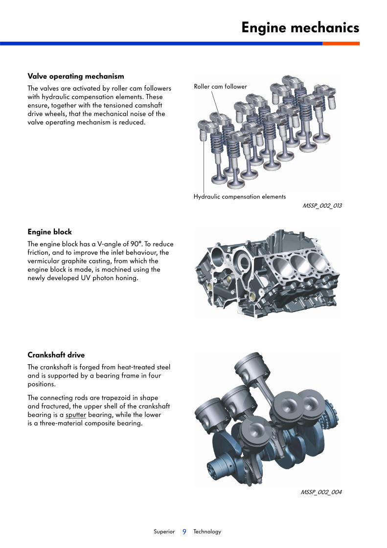
Valve operating mechanism
The valves are activated by roller cam followers with hydraulic compensation elements. These ensure, together with the tensioned camshaft drive wheels, that the mechanical noise of the valve operating mechanism is reduced.
Engine block
The engine block has a V-angle of 90°. To reduce friction, and to improve the inlet behaviour, the vermicular graphite casting, from which the engine block is made, is machined using the newly developed UV photon honing.
Crankshaft drive
The crankshaft is forged from heat-treated steel and is supported by a bearing frame in four positions.
The connecting rods are trapezoid in shape and fractured, the upper shell of the crankshaft bearing is a sputter bearing, while the lower is a three-material composite bearing.
Engine mechanics
Roller cam follower
MSSP_002_004
Hydraulic compensation elementsMSSP_002_013
10Superior Technology
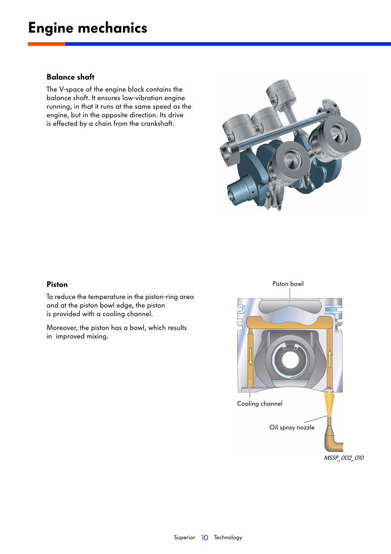
Balance shaft
The V-space of the engine block contains the balance shaft. It ensures low-vibration engine running, in that it runs at the same speed as the engine, but in the opposite direction. Its drive is effected by a chain from the crankshaft.
Piston
To reduce the temperature in the piston-ring area and at the piston bowl edge, the piston is provided with a cooling channel.
Moreover, the piston has a bowl, which results in improved mixing.
Engine mechanics
Piston bowl
MSSP_002_010
Cooling channel
Oil spray nozzle

11Superior Technology
MSSP_002_005
Bearing frame
A stable bearing frame acts as the main bearing assembly, which receives the crankshaft bearings and also serves to reinforce the engine block.
Oil sump
The oil sump is specially designed for use in inclined positions, it comprises the oil sump upper part and the oil sump lower part.
The low oil suction position guarantees a reliable oil supply, even during yawing movements.
Engine mechanics
Oil sump upper part
Oil sump lower part
MSSP_002_009
12Superior Technology
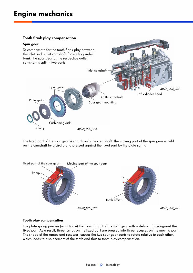
Tooth flank play compensation
Spur gear
To compensate for the tooth flank play between the inlet and outlet camshaft, for each cylinder bank, the spur gear of the respective outlet camshaft is split in two parts.
Engine mechanics
Tooth play compensation
The plate spring presses (axial force) the moving part of the spur gear with a defined force against the fixed part. As a result, three ramps on the fixed part are pressed into three recesses on the moving part. The shape of the ramps and recesses, causes the two spur gear parts to rotate relative to each other, which leads to displacement of the teeth and thus to tooth play compensation.
MSSP_002_014
MSSP_002_015
Left cylinder head
The fixed part of the spur gear is shrunk onto the cam shaft. The moving part of the spur gear is held on the camshaft by a circlip and pressed against the fixed part by the plate spring.
MSSP_002_016
Circlip
Plate spring
Spur gears
Cushioning disk
Spur gear mounting
Inlet camshaft
Ramp
MSSP_002_017
Outlet camshaft
Tooth offset
Moving part of the spur gearFixed part of the spur gear

13Superior Technology
Chain drive
The chain drive comprises four Simplex bushing chains, that are arranged in two planes. They respectively drive the inlet camshafts of the right and left cylinder banks, the oil pump and the balance shaft.
The four Simplex bushing chains are sub-divided into drives A, B, C and D.
Driving takes place from the crankshaft via chain drive A over the driving wheels for the left and right control chains, from where the camshafts are driven using chain drives B and C.
The necessary transmission between crank- and camshafts is realized by the drive wheels for the timing chains.
The oil pump and the balance shaft are drive from the crankshaft via chain drive D.
Hydraulic chain tensioners with integral non-return valves are used to tension the chains.
Engine mechanics
Timing chain for camshaft driveCylinder bank 2Chain drive B
Drive chain for timing assembly Chain drive A
Timing chain for camshaft driveCylinder bank 1Chain drive C
Drive chain for oil pump and balance shaftChain drive D
Crankshaft
Driving wheel for left timing chain
Driving wheel for right timing chain
Chain tensionerChain tensioner
Chain tensioner
Chain tensioner with slide bar
MSSP_002_011

14Superior Technology
Toothed belt drive for high pressure pump
The high pressure pump for the common-rail fuel injection system is located on the front side of the engine and is driven by a toothed belt from the inlet camshaft of cylinder bank 1. Tensioning of the toothed belt is guaranteed by a mechanical tensioner.
Auxiliary drive system
Driving of auxiliary equipment is achieved using a ribbed V-belt.
The following are driven:
• 12V alternator for engine operation and battery charging,
• the coolant pump,
• optionalthe power-steering pump for boots with a Z-drive
• and optionally an additional 230V alternator.
Engine mechanics
MSSP_002_018
Toothed belt pulley for the high pressure pump with balance weight
Toothed belt-drive pulley
Toothed belt tensioner
MSSP_002_007
Upper idler pulley
AlternatorCoolant pump
Power steering
Tensioner
Crankshaft belt pulley
Seawater pump
Lower idler pulley
15Superior Technology
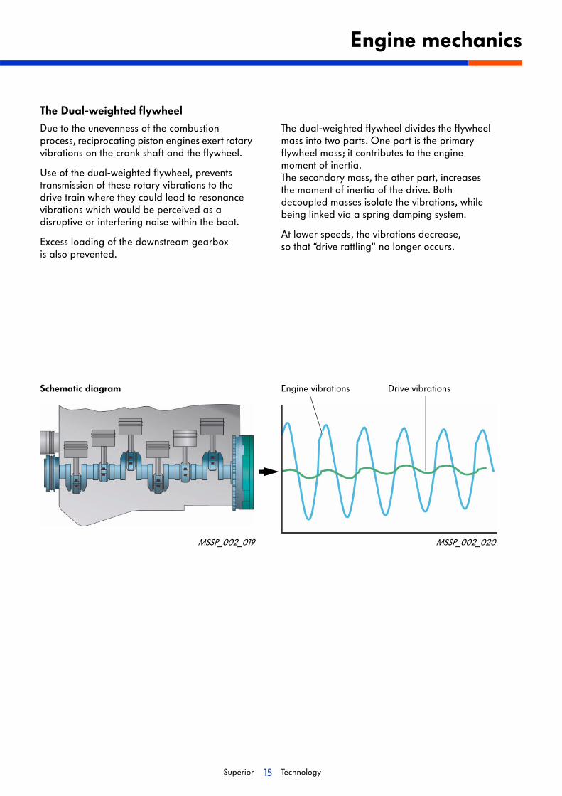
The Dual-weighted flywheel
Due to the unevenness of the combustion process, reciprocating piston engines exert rotary vibrations on the crank shaft and the flywheel.
Use of the dual-weighted flywheel, prevents transmission of these rotary vibrations to the drive train where they could lead to resonance vibrations which would be perceived as a disruptive or interfering noise within the boat.
Excess loading of the downstream gearbox is also prevented.
The dual-weighted flywheel divides the flywheel mass into two parts. One part is the primary flywheel mass; it contributes to the engine moment of inertia. The secondary mass, the other part, increases the moment of inertia of the drive. Both decoupled masses isolate the vibrations, while being linked via a spring damping system.
At lower speeds, the vibrations decrease, so that “drive rattling" no longer occurs.
Engine mechanics
MSSP_002_019 MSSP_002_020
Engine vibrations Drive vibrationsSchematic diagram

16Superior Technology
Oil circuit
Overview
Engine lubrication
MSSP_002_021
Oil pressure regulating valve
The oil pressure regulating valve controls the engine oil pressure and is integrated in the oil pump.
The engine oil pressure should be at least 1.8 bar when the engine is idling and above 2000 rpm should be at least 4.0 bar.
Overpressure valve
The overpressure valve opens at approx. 11 bar and thus protects the engine against too high an oil pressure (e. g. during cold starting).
Turbocharger
Oil filter module
Oil cooler
Overpressure valve
Oil pressure regulating valve
Oil pumpOil sump
Oil spray nozzles
Oil return

17Superior Technology
Oil pump
An internal gear pump, operating according to the Duocentrip-principle, is used as an oil pump. The intake connector is matched to its use in a boat engine.
Oil filter
The oil filter module contains the oil filter, the oil cooler as well as the cyclone oil separator with a pressure regulating valve for crankcase ventilation. It is installed in the V-space of the engine.
Engine lubrication
MSSP_002_055
MSSP_002_056
Oil filter
Cyclone separator with pressure regulating valve
Oil cooler
18Superior Technology
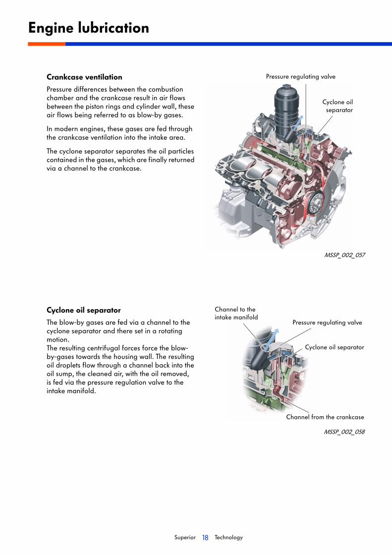
Crankcase ventilation
Pressure differences between the combustion chamber and the crankcase result in air flows between the piston rings and cylinder wall, these air flows being referred to as blow-by gases.
In modern engines, these gases are fed through the crankcase ventilation into the intake area.
The cyclone separator separates the oil particles contained in the gases, which are finally returned via a channel to the crankcase.
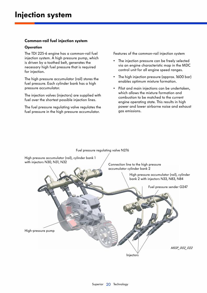
Cyclone oil separator
The blow-by gases are fed via a channel to the cyclone separator and there set in a rotating motion. The resulting centrifugal forces force the blow-by-gases towards the housing wall. The resulting oil droplets flow through a channel back into the oil sump, the cleaned air, with the oil removed, is fed via the pressure regulation valve to the intake manifold.
Engine lubrication
MSSP_002_057
Pressure regulating valve
Cyclone oilseparator
MSSP_002_058
Channel from the crankcase
Channel to the intake manifold
Pressure regulating valve
Cyclone oil separator

19Superior Technology
Pressure regulating valve
The pressure regulating valve is contained in the cover of the cyclone oil separator. It regulates the pressure for ventilating the crankcase and comprises a membrane and a compression spring.
Pressure regulating valve open
The force of the compression spring acting on the membrane, opens the channel to the intake manifold sothe cleaned air can be sucked into the intake manifold.
Pressure regulating valve closed
As the vacuum pressure in the intake manifold increases, the membrane closes against the spring force. This prevents formation of a too high vacuum pressure in the crankcase via the intake manifold.
Engine lubrication
MSSP_002_059
To the intake manifoldMembrane
Compression spring
From the crankcase
To the crankcase
MSSP_002_057
20Superior Technology
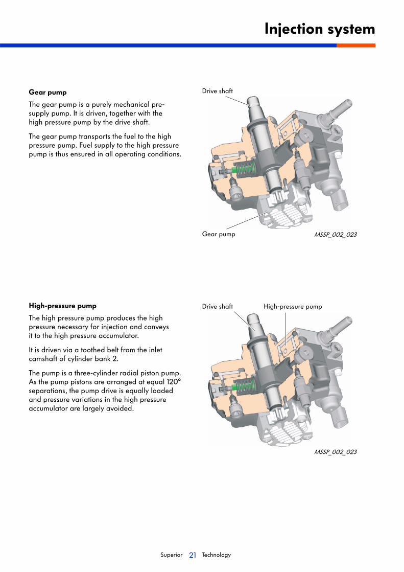
Common-rail fuel injection system
Operation
The TDI 225-6 engine has a common-rail fuel injection system. A high pressure pump, which is driven by a toothed belt, generates the necessary high fuel pressure that is required for injection.
The high pressure accumulator (rail) stores the fuel pressure. Each cylinder bank has a high pressure accumulator.
The injection valves (injectors) are supplied with fuel over the shortest possible injection lines.
The fuel pressure regulating valve regulates the fuel pressure in the high pressure accumulator.
Features of the common-rail injection system
• The injection pressure can be freely selected via an engine characteristic map in the MDC control unit for all engine speed ranges.
• The high injection pressure (approx. 1600 bar) enables optimum mixture formation.
• Pilot and main injections can be undertaken, which allows the mixture formation and combustion to be matched to the current engine operating state. This results in high power and lower airborne noise and exhaust gas emissions.
Injection system
High pressure accumulator (rail), cylinder bank 1with injectors N30, N31, N32
Fuel pressure regulating valve N276
Connection line to the high pressure accumulator cylinder bank 2
MSSP_002_022
High pressure accumulator (rail), cylinder bank 2 with injectors N33, N83, N84
Injectors
Fuel pressure sender G247
High-pressure pump
21Superior Technology
Gear pump
The gear pump is a purely mechanical pre-supply pump. It is driven, together with the high pressure pump by the drive shaft.
The gear pump transports the fuel to the high pressure pump. Fuel supply to the high pressure pump is thus ensured in all operating conditions.
High-pressure pump
The high pressure pump produces the high pressure necessary for injection and conveys it to the high pressure accumulator.
It is driven via a toothed belt from the inlet camshaft of cylinder bank 2.
The pump is a three-cylinder radial piston pump. As the pump pistons are arranged at equal 120° separations, the pump drive is equally loaded and pressure variations in the high pressure accumulator are largely avoided.
Injection system
MSSP_002_023
MSSP_002_023
Drive shaft
Gear pump
Drive shaft High-pressure pump

22Superior Technology
Operating principle
Gear pump
The gear pump comprises two gear wheels, which turn in opposite directions. One of the gear wheels is driven from the drive shaft of the high pressure pump.
The rotating gear wheels transport the fuel in the gaps between the teeth alongside the pump wall up to the pressure side.
If the fuel pressure increases above 5.5 bar, the safety valve opens and the fuel is transported back to the suction side.
Regulating piston
The regulating piston is pressed by the control pressure against the force of the spring and opens the outlet cross-section to the high pressure pump.
The magnitude of the control pressure regulates the fuel metering valve N290, which is controlled by the MDC control unit.
If the control pressure increases, more fuel reaches the pump piston, if the control pressure decreases, less fuel reaches the pump piston.
Injection system
MSSP_002_026
Suction side
Pressure side
Drive gear
Pump wall
Safety valve
Pump piston
Outlet valve
Disk inlet valve
Gear pump
MSSP_002_027
Regulating piston
Control pressure
SpringCam sheave
Pump wall
Fuel metering valve N290
23Superior Technology
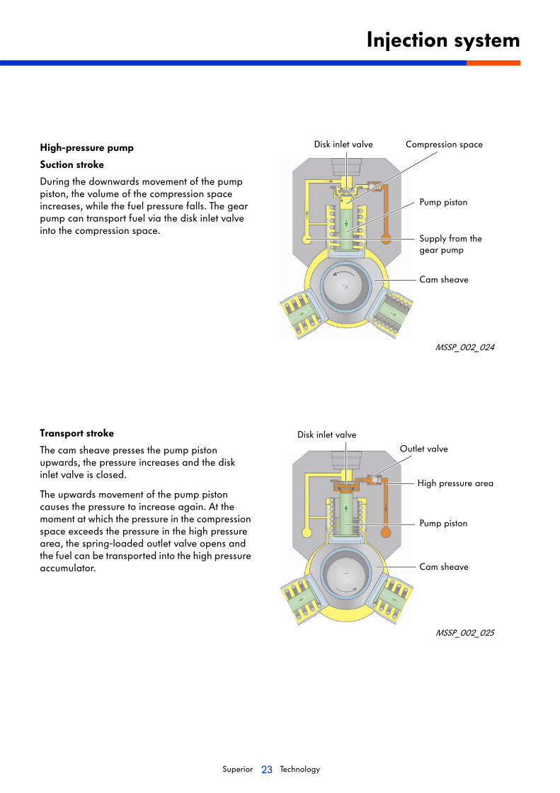
High-pressure pump
Suction stroke
During the downwards movement of the pump piston, the volume of the compression space increases, while the fuel pressure falls. The gear pump can transport fuel via the disk inlet valve into the compression space.
Transport stroke
The cam sheave presses the pump piston upwards, the pressure increases and the disk inlet valve is closed.
The upwards movement of the pump piston causes the pressure to increase again. At the moment at which the pressure in the compression space exceeds the pressure in the high pressure area, the spring-loaded outlet valve opens and the fuel can be transported into the high pressure accumulator.
Injection system
MSSP_002_024
MSSP_002_025
Compression space
Pump piston
Disk inlet valve
Supply from thegear pump
Cam sheave
Outlet valve
High pressure area
Pump piston
Cam sheave
Disk inlet valve
24Superior Technology
Injection system
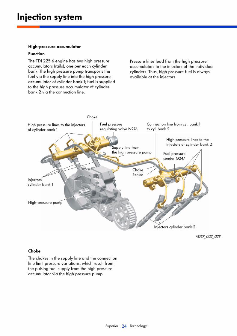
High-pressure accumulator
Function
The TDI 225-6 engine has two high pressure accumulators (rails), one per each cylinder bank. The high pressure pump transports the fuel via the supply line into the high pressure accumulator of cylinder bank 1; fuel is supplied to the high pressure accumulator of cylinder bank 2 via the connection line.
Pressure lines lead from the high pressure accumulators to the injectors of the individual cylinders. Thus, high pressure fuel is always available at the injectors.
Choke
The chokes in the supply line and the connection line limit pressure variations, which result from the pulsing fuel supply from the high pressure accumulator via the high pressure pump.
MSSP_002_028
Injectors cylinder bank 2
Injectors cylinder bank 1
High pressure lines to the injectors of cylinder bank 1
High pressure lines to the injectors of cylinder bank 2
Choke
Fuel pressureregulating valve N276
Fuel pressuresender G247
High-pressure pump
Connection line from cyl. bank 1 to cyl. bank 2
Supply line from the high pressure pump
Return
Choke

25Superior Technology
The injectors are located in the cylinder heads. They inject fuel in the correct amount and at the correct point in time to the combustion chamber. Control is via the MDC control unit.
The injectors of the TDI 225-6 engine are piezoelectrically controlled, i.e. conforming to the state of the art in diesel engine construction.
This yields the following advantages:
• the switching speed is four times faster than for solenoid valves,
• the mass moved at the nozzle needle is 75 % less,
• the switching times are shorter,
• more injections can be carried out per work cycle and
• the injected fuel quantity can be more precisely metered.
Injection system
Cylinder injectors (N30, N31, N32, N33, N83 and N84)
MSSP_002_030MSSP_002_029
Fuel supply (high pressure connection) Fuel supply (high pressure connection)
Electrical connection
Filter cartridge
Fuel return
Coupling piston
Valve piston
Valve piston spring
Control valve
Choke plate
Nozzle spring
Seal
Nozzle needle
Piezoelectric element
26Superior Technology
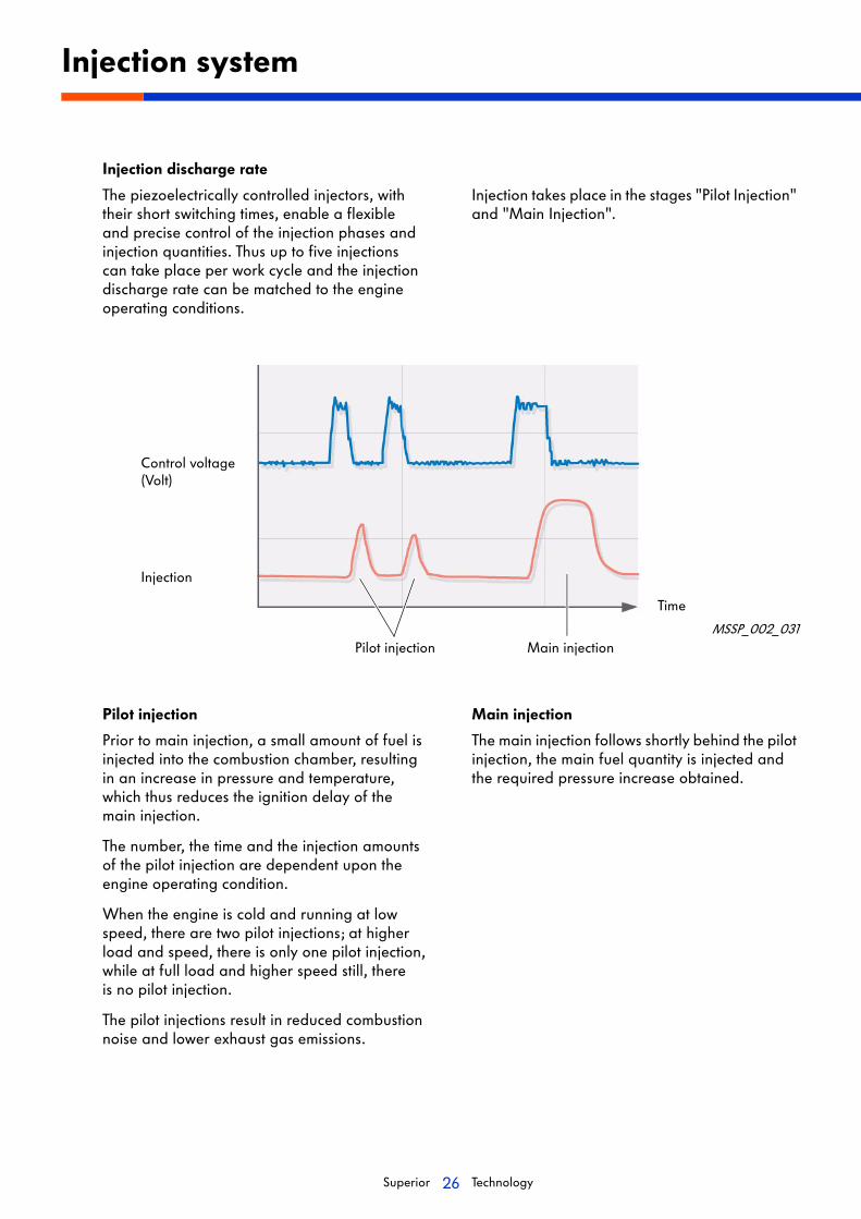
Injection discharge rate
The piezoelectrically controlled injectors, with their short switching times, enable a flexible and precise control of the injection phases and injection quantities. Thus up to five injections can take place per work cycle and the injection discharge rate can be matched to the engine operating conditions.
Injection takes place in the stages "Pilot Injection" and "Main Injection".
Injection system
MSSP_002_031
Control voltage(Volt)
Pilot injection
Prior to main injection, a small amount of fuel is injected into the combustion chamber, resulting in an increase in pressure and temperature, which thus reduces the ignition delay of the main injection.
The number, the time and the injection amounts of the pilot injection are dependent upon the engine operating condition.
When the engine is cold and running at low speed, there are two pilot injections; at higher load and speed, there is only one pilot injection, while at full load and higher speed still, there is no pilot injection.
The pilot injections result in reduced combustion noise and lower exhaust gas emissions.
Main injection
The main injection follows shortly behind the pilot injection, the main fuel quantity is injected and the required pressure increase obtained.
Pilot injection Main injection
Time
Injection

27Superior Technology
Fine element diesel filter with water warning device
The purpose of the fine element diesel filter is,to filter out the smallest possible impurities from the diesel. To bleed the fuel system, the fine element filter has a hand pump.
Circulation pre-filterwith water separator (optional)
The circulation water separator in installed between the fuel tank and the fuel pump. The precise installation location is dependent on the boat type.
Injection system
MSSP_002_033
MSSP_002_034
A functional description for both filters, can be found in SSP M001.
Fine element fuel filter
Water drainage channel
Warning switch
Alternative outlet
Alternative inlet
Outlet
Inlet
Filter element
Guide vaneBowl section
Guide vane
Bowl bottom
Water drain
28Superior Technology
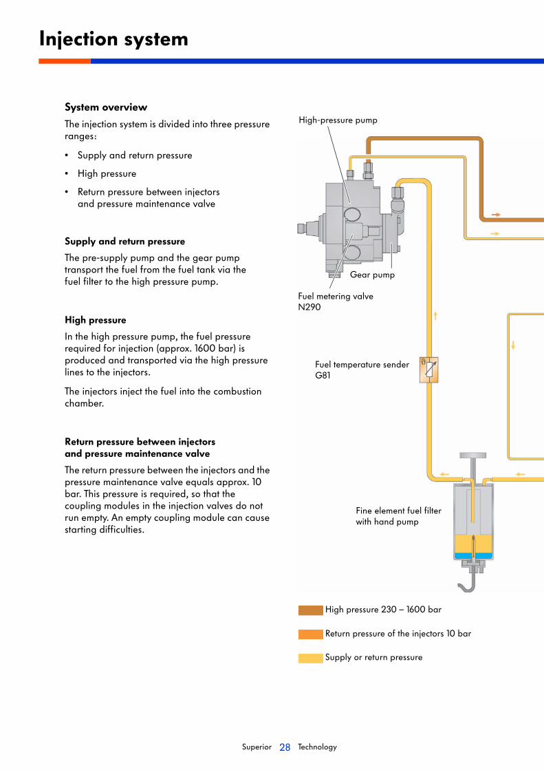
System overview
The injection system is divided into three pressure ranges:
• Supply and return pressure
• High pressure
• Return pressure between injectors and pressure maintenance valve
Supply and return pressure
The pre-supply pump and the gear pump transport the fuel from the fuel tank via the fuel filter to the high pressure pump.
High pressure
In the high pressure pump, the fuel pressure required for injection (approx. 1600 bar) is produced and transported via the high pressure lines to the injectors.
The injectors inject the fuel into the combustion chamber.
Return pressure between injectors and pressure maintenance valve
The return pressure between the injectors and the pressure maintenance valve equals approx. 10 bar. This pressure is required, so that the coupling modules in the injection valves do not run empty. An empty coupling module can cause starting difficulties.
Injection system
High pressure 230 – 1600 bar
Return pressure of the injectors 10 bar
Supply or return pressure
High-pressure pump
Gear pump
Fuel metering valveN290
Fuel temperature senderG81
Fine element fuel filter with hand pump
29Superior Technology
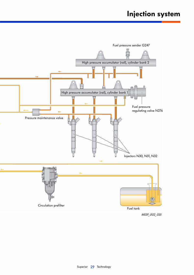
Injection system
Fuel pressure sender G247
High pressure accumulator (rail), cylinder bank 2
High pressure accumulator (rail), cylinder bank 1
Fuel pressure regulating valve N276
Pressure maintenance valve
Injectors N30, N31, N32
Circulation prefilterFuel tank
MSSP_002_035
30Superior Technology
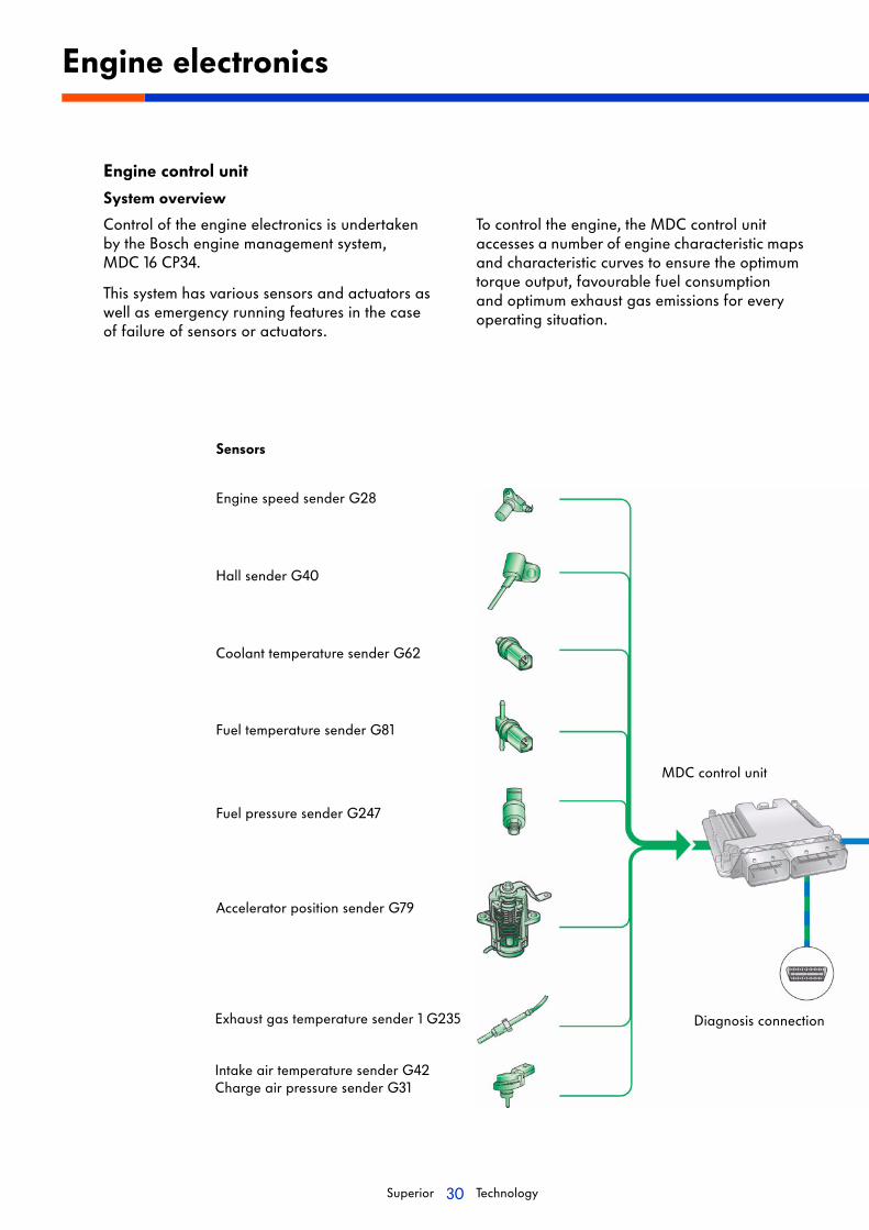
Engine control unit
System overview
Control of the engine electronics is undertaken by the Bosch engine management system, MDC 16 CP34.
This system has various sensors and actuators as well as emergency running features in the case of failure of sensors or actuators.
To control the engine, the MDC control unit accesses a number of engine characteristic maps and characteristic curves to ensure the optimum torque output, favourable fuel consumption and optimum exhaust gas emissions for every operating situation.
Engine electronics
Engine speed sender G28
Hall sender G40
Coolant temperature sender G62
Fuel temperature sender G81
Fuel pressure sender G247
Accelerator position sender G79
Exhaust gas temperature sender 1 G235
Intake air temperature sender G42Charge air pressure sender G31
Sensors
Diagnosis connection
MDC control unit
31Superior Technology
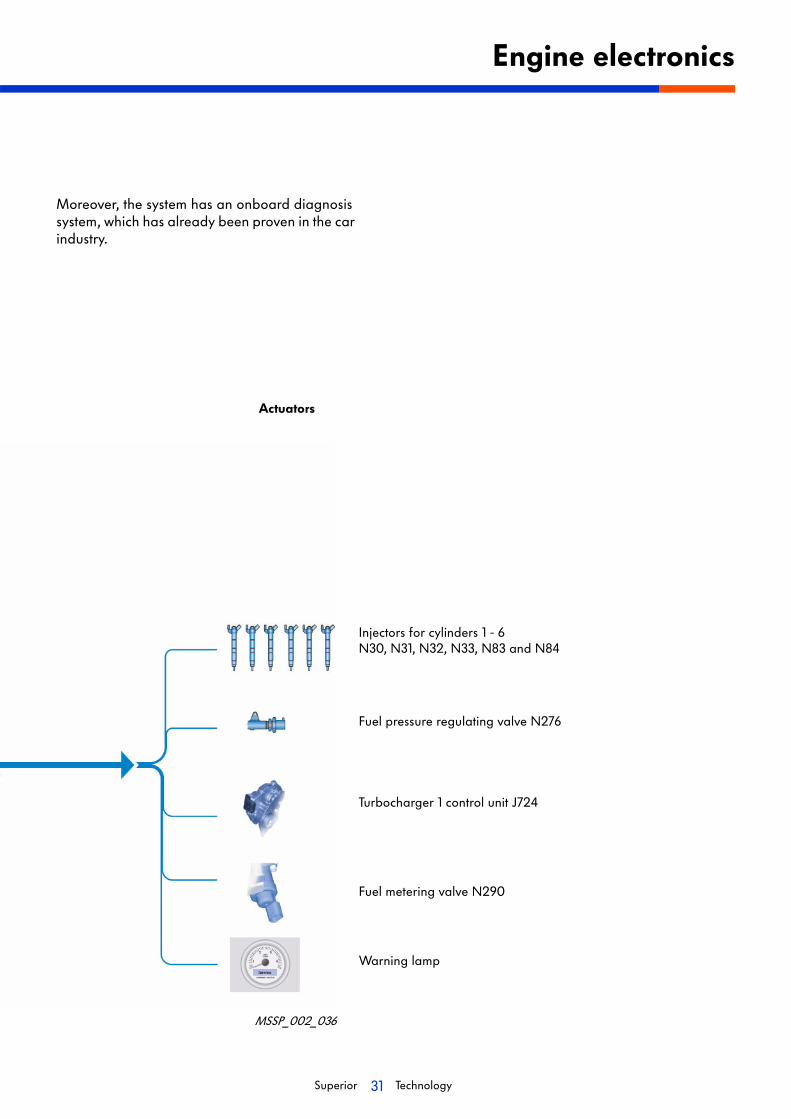
Moreover, the system has an onboard diagnosis system, which has already been proven in the car industry.
Engine electronics
Injectors for cylinders 1 - 6N30, N31, N32, N33, N83 and N84
Fuel pressure regulating valve N276
Turbocharger 1 control unit J724
Fuel metering valve N290
Warning lamp
Actuators
MSSP_002_036
32Superior Technology
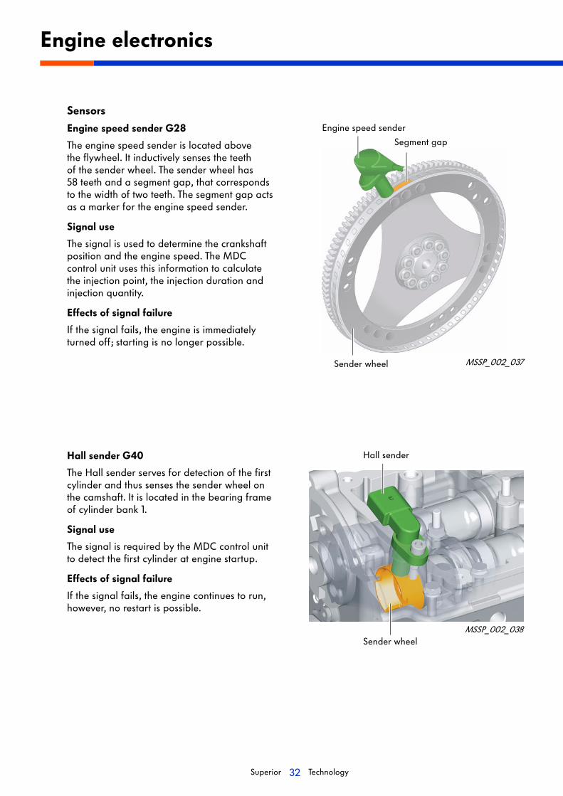
Sensors
Engine speed sender G28
The engine speed sender is located above the flywheel. It inductively senses the teeth of the sender wheel. The sender wheel has 58 teeth and a segment gap, that corresponds to the width of two teeth. The segment gap acts as a marker for the engine speed sender.
Signal use
The signal is used to determine the crankshaft position and the engine speed. The MDC control unit uses this information to calculate the injection point, the injection duration and injection quantity.
Effects of signal failure
If the signal fails, the engine is immediately turned off; starting is no longer possible.
Hall sender G40
The Hall sender serves for detection of the first cylinder and thus senses the sender wheel on the camshaft. It is located in the bearing frame of cylinder bank 1.
Signal use
The signal is required by the MDC control unit to detect the first cylinder at engine startup.
Effects of signal failure
If the signal fails, the engine continues to run, however, no restart is possible.
Engine electronics
Hall sender
MSSP_002_037
Engine speed sender
Segment gap
Sender wheel
Sender wheelMSSP_002_038
33Superior Technology
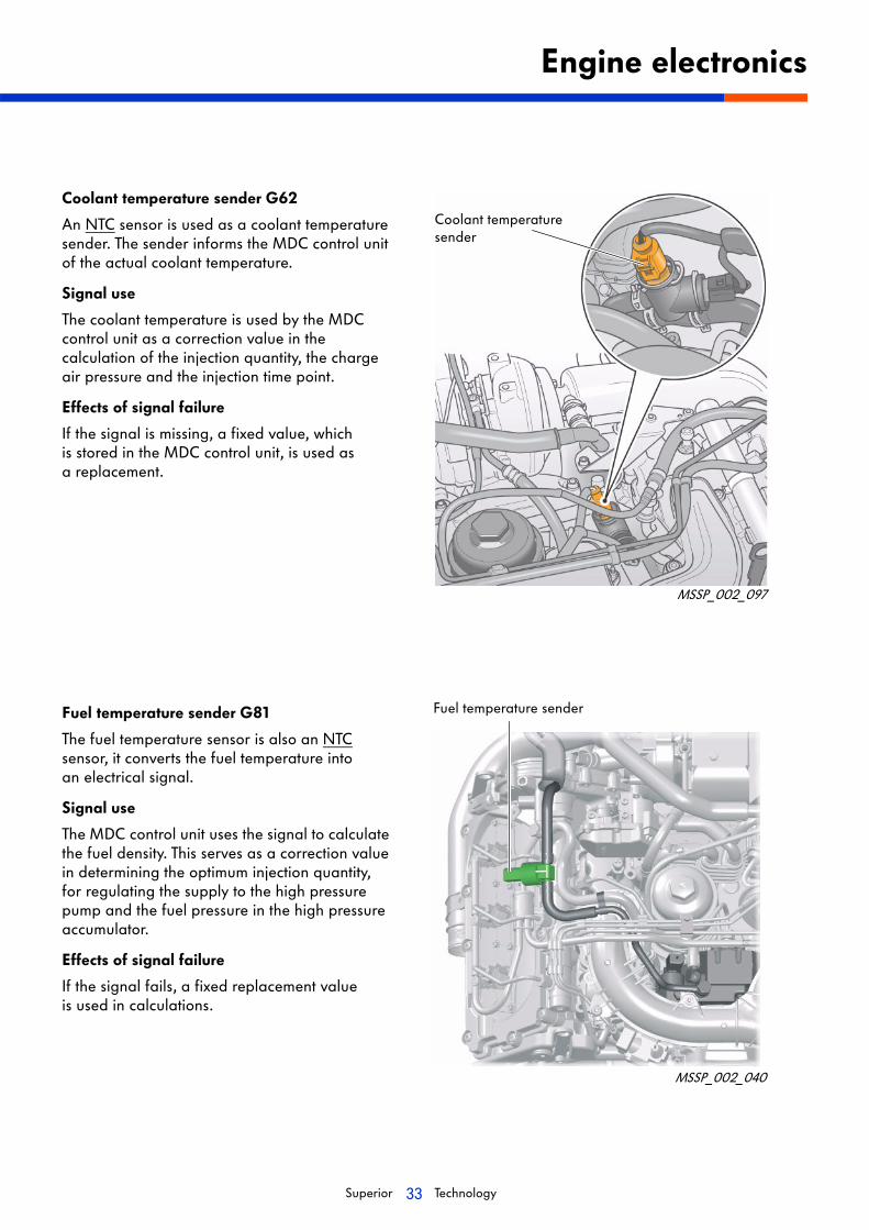
Coolant temperature sender G62
An NTC sensor is used as a coolant temperature sender. The sender informs the MDC control unit of the actual coolant temperature.
Signal use
The coolant temperature is used by the MDC control unit as a correction value in the calculation of the injection quantity, the charge air pressure and the injection time point.
Effects of signal failure
If the signal is missing, a fixed value, which is stored in the MDC control unit, is used as a replacement.
Fuel temperature sender G81
The fuel temperature sensor is also an NTC sensor, it converts the fuel temperature into an electrical signal.
Signal use
The MDC control unit uses the signal to calculate the fuel density. This serves as a correction value in determining the optimum injection quantity, for regulating the supply to the high pressure pump and the fuel pressure in the high pressure accumulator.
Effects of signal failure
If the signal fails, a fixed replacement value is used in calculations.
Engine electronics
Fuel temperature sender
MSSP_002_040
MSSP_002_097
Coolant temperature sender

34Superior Technology
Fuel pressure sender G247
The fuel pressure sender is positioned at the high pressure accumulator of cylinder bank 2. It converts the actual fuel high pressure into an electrical signal.
Signal use
The MDC control unit, calculates the required fuel injection quantity and injector opening times.
Effect of signal failure
The MDC control unit calculates using a stored fixed value, engine performance is reduced.
Accelerator position sender G79
The accelerator position sender is located close to the central electrics. Its electrical signal informs the engine control unit of the accelerator position.
Signal use
The MDC control unit determines the position of the accelerator from this value and the corresponding power requirement of the skipper. From this, the injection quantity and time for beginning injection is calculated.
Effect of signal failure
If the engine control unit does not receive a signal, a fixed stored value is used as a replacement value. The engine runs with a high engine idling speed (1400 rpm), so that the skipper can reach the closest landing stage. It is no longer possible to accelerate.
Engine electronics
MSSP_002_041
MSSP_002_042
Shaft
Potentiometer with idling speed switch
Fuel pressure sender
Coil connector

35Superior Technology
Exhaust gas temperature sender 1 G235
The exhaust gas temperature sender is located in the exhaust pipe prior to the turbocharger and is a PTC sensor. The MDC control unit uses the signal to calculate the actual exhaust gas temperature.
Signal use
The signal is used to determine the actual exhaust gas temperature. If the exhaust gas temperature is too high, the charge air pressure is reduced, thus protecting the turbocharger from overheating.
Effect of failure
If the signal fails, the charge air pressure is reduced and with it the engine power.
Intake air temperature sender G42
Charge air pressure sender G31
Both senders are integrated in a housing and located in the intake manifold.
Signal use
The MDC control unit calculates the charge air pressure as well as the effect of the ambient air temperature on the charge air pressure and uses the signals for charge air pressure regulation.
Effect of signal failure
Signal failure results in reduced engine performance.
Engine electronics
MSSP_002_043
MSSP_002_044
Exhaust gas temperature sender
Intake air temperature sender G42Charge air pressure sender G31

36Superior Technology
Actuators
Injectors N30, N31, N32, N33, N83 and N84
The injectors inject the fuel directly into the combustion chamber. Control is via the MDC control unit.
Function
The injectors work according to the inverse piezoelectric effect.
Piezoelectric effect
If a pressure acts on a piezoelectric element, a measurable voltage is generated.
Inverse piezoelectric effect
If an electric voltage is applied to a piezoelectric element, the crystal structure reacts by expanding.
Engine electronics
MSSP_002_030
Inverse piezoelectric effect
Star
t len
gth
and
leng
th e
xten
sion
Schematic view of the crystal structure
Voltage source
MSSP_002_046
Fuel supply (high pressure connection)
Electrical connection
Filter cartridge
Fuel return
Piezoelectric element
Coupling piston
Valve piston
Valve piston spring
Control valve
Choke plate
Nozzle spring
Seal
Nozzle needle

37Superior Technology
Coupling module
The coupling piston and the valve piston, together, form the coupling module. Because the coupling module works like a hydraulic cylinder, it transmits the longitudinal expansion of the piezoelectric element and activates the control valve.
There is always fuel between the coupling piston, the valve piston and the control valve, said fuel acting as a pressure cushion. The fuel pressure of the pressure cushion is always equal to 10 bar, which is guaranteed by the choke valve.
Hydraulic principle
The different piston diameters mean the forces applied by the pistons have a ratio that is in proportion to that of the different piston diameters
The surface area of the coupling piston is greater that the surface area of the valve piston, so that the valve piston is activated by the coupling piston.
The surface area of the valve piston is greater that the surface area of the control valve, so that the control valve is activated by the valve piston.
Engine electronics
MSSP_002_047
MSSP_002_048
Coupling piston
Pressure cushion
Valve piston
Pressure cushion
Control valve
Return pressure of the injectors 10 bar
High pressure 230 to 1600 bar
Pistondiameter in comparison
Coupling piston
Valve piston
Control valve

38Superior Technology
Fuel pressure regulating valve N276
The fuel pressure regulating valve is located at the high pressure accumulator of cylinder bank 1 on the flywheel side.
Purpose
The valve regulates the fuel pressure on the high pressure side. Control is via the MDC control unit.
Effect of failure
Failure of the regulating valve means that insufficient fuel high pressure can be produced, motor running is thus not possible.
Engine electronics
Fuel pressure regulating valve
MSSP_002_049
Function
If there is no power to the valve, the fuel can flow past the valve needle into the fuel return line. If the engine is operating, the MDC control unit controls the solenoid with a PWM signal. This causes the valve anchor to be drawn in and the valve needle to be pressed into its seat. The PWM control permits matching of the fuel pressure in the high pressure accumulator to the engine requirements.
MSSP_002_050
High pressure accumulator (rail)
Valve needle
Solenoid
Return line to the fuel tank
Valve anchor
Valve spring
39Superior Technology
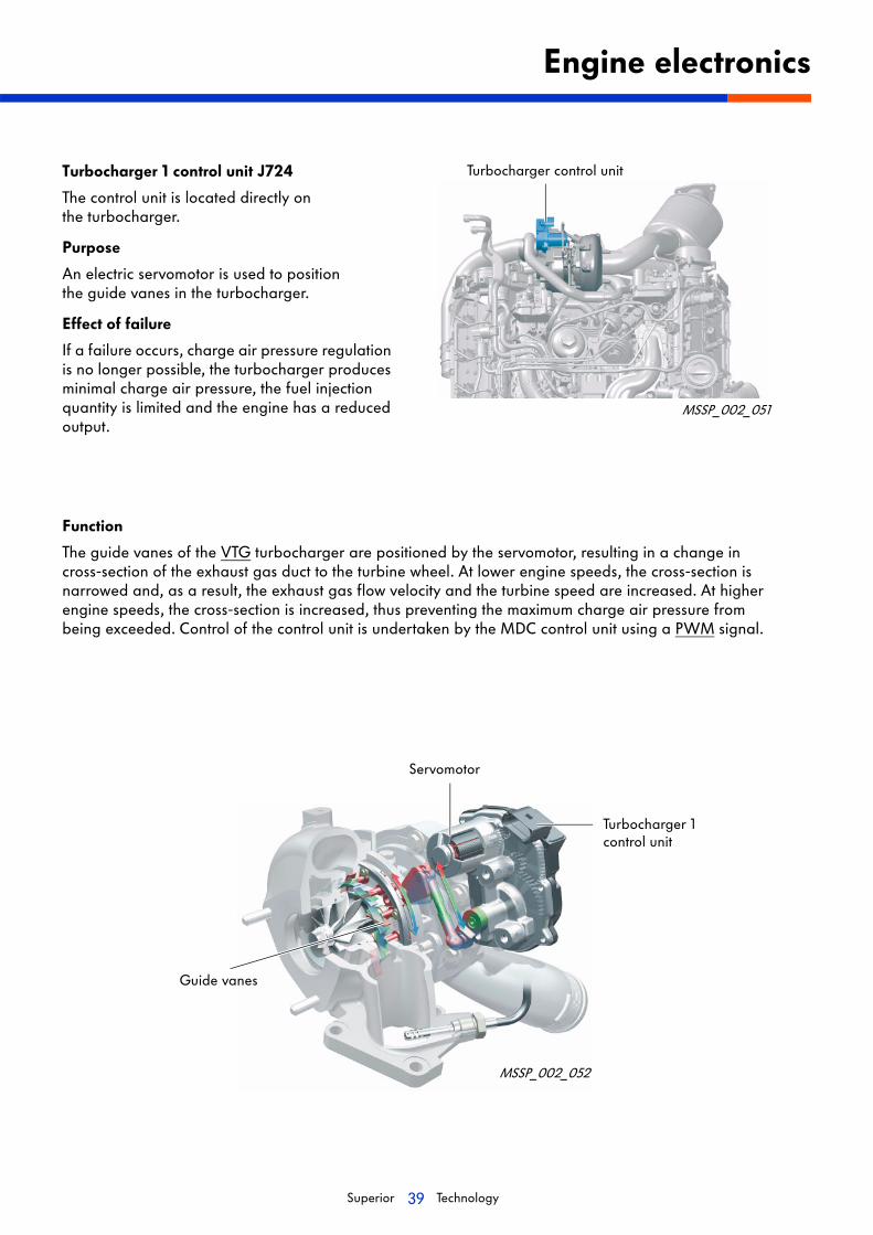
Turbocharger 1 control unit J724
The control unit is located directly on the turbocharger.
Purpose
An electric servomotor is used to position the guide vanes in the turbocharger.
Effect of failure
If a failure occurs, charge air pressure regulation is no longer possible, the turbocharger produces minimal charge air pressure, the fuel injection quantity is limited and the engine has a reduced output.
Engine electronics
Turbocharger control unit
MSSP_002_051
MSSP_002_052
Function
The guide vanes of the VTG turbocharger are positioned by the servomotor, resulting in a change in cross-section of the exhaust gas duct to the turbine wheel. At lower engine speeds, the cross-section is narrowed and, as a result, the exhaust gas flow velocity and the turbine speed are increased. At higher engine speeds, the cross-section is increased, thus preventing the maximum charge air pressure from being exceeded. Control of the control unit is undertaken by the MDC control unit using a PWM signal.
Servomotor
Turbocharger 1 control unit
Guide vanes

40Superior Technology
Fuel metering valve N290
The fuel metering valve is located at the high pressure pump. Control is via the MDC control unit.
Purpose
The fuel quantity, that flows to the high pressure pump, is regulated by the fuel metering valve. Thus the pressure that must be produced by the high pressure pump, is dependent on the engine operating state.
Effect of failure
The piston spring presses the regulating piston into its base position. Engine performance is reduced, the system is in emergency running mode.
Engine electronics
MSSP_002_053
MSSP_002_054
Function
If the valve is not controlled, the piston spring presses the regulating piston, to the left into its base position. Only the minimum flow cross-section is enabled. Thus only a small fuel quantity can flow to the high pressure pump. The fuel metering valve is opened.
Control of the fuel metering valve is via a PWM signal from the MDC control unit, it is thereby synchronously closed. As a result a control pressure arises that presses the regulating piston against the spring force of the regulating spring, the flow cross-section is increased.
Control using a PWM signal means that the flow cross-section can be matched to running requirements.
Pump piston
Outlet valve
Disk inlet valve
Fuel metering valve N290
Control pressure
Piston springCam sheave
Regulating piston
PWM signal
To the high pressure accumulator (rail)
Return to the gear pump
Supply from the gear pump
Overpressure valve
41Superior Technology
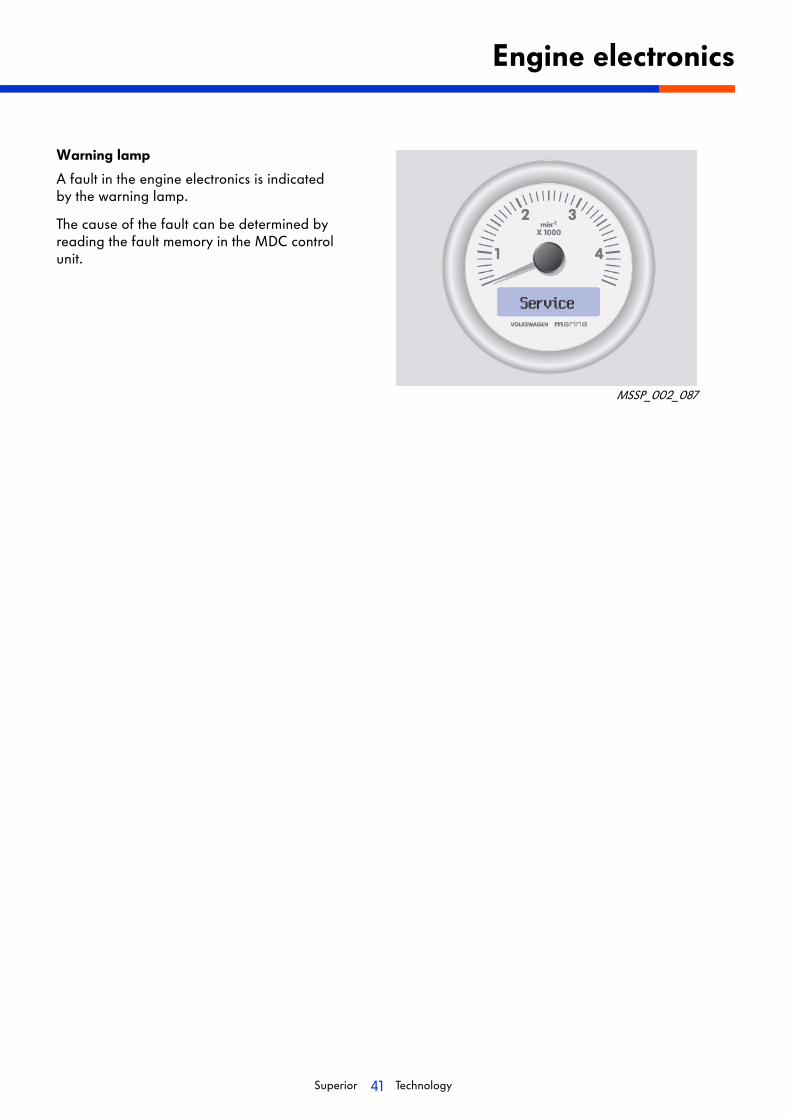
Warning lamp
A fault in the engine electronics is indicated by the warning lamp.
The cause of the fault can be determined by reading the fault memory in the MDC control unit.
Engine electronics
MSSP_002_087

42Superior Technology
Cooling system
Coolant circuit
Description
To keep the engine free of aggressive media, such as saltwater, Volkswagen marine engines are equipped with a dual-circuit cooling system.
Primary circuit
The coolant in the engine circuit (primary circuit) is comprised of antifreeze, corrosion inhibitor and water. The coolant circuit is a closed system. The heat is given off to the sea in a heat exchanger, through which sea water flows.
The engine coolant pump transports the coolant through the engine, the thermostat switches between the internal and external engine coolant circuit, dependent on the engine temperature.
Secondary circuit
The seawater circuit (secondary circuit) is an open circuit in which the seawater (raw water) is sucked in and is routed to the outside again via the exhaust system after it has flowed through the heat exchanger.
The raw water pump sucks the seawater through the seawater filter and transports it to the heat exchanger. The seawater exits again via the exhaust pipe.

43Superior Technology
Cooling system
Overview
Components
1 Engine
2 Oil cooler
3 Exhaust manifold cylinder bank, left
4 Expansion tank
5 External engine cooling circuit
6 External heating supply
7 External heating return
8 Gearbox oil cooler
9 Seawater coolant circuit
10 Main heat exchanger
11 Seawater
12 See water filter and raw water pump
13 Intercooler
14 Thermostat (70 °C)
15 Engine coolant pump
16 Exhaust manifold cylinder bank, right
MSSP_002_061

44Superior Technology
Heat exchanger
The engine heat is given off by the coolant to the seawater within the heat exchanger.
The sacrificial anode is also located in the heat exchanger.
Intercooler
The compressed combustion air, which has been sucked through the turbocharger is cooled in the intercooler.
Gearbox radiator
The gear oil originating from attached drives is cooled in the gearbox radiator by the seawater flowing through it.
Cooling system
MSSP_002_066
MSSP_002_069
MSSP_002_070
A detailed description of the operation of the sacrificial anode is found in SSP M001, page 68.

45Superior Technology
Seawater pump
The seawater required for engine cooling is sucked in from outboard through the impeller of the seawater pump.
The pump is driven by a plug connection directly from the crankshaft.
Seawater outlet
In the exhaust pipe, the seawater required for cooling is added to the exhaust gas fed out through the boat exhaust gas system (wet exhaust).
Exhaust manifold
Because the temperature of the exhaust gases can be very high, the exhaust gas manifold is cooled by the primary circuit coolant.
Cooling system
MSSP_002_068
MSSP_002_065
MSSP_002_067

46Superior Technology
Turbocharger
Function
The charge air pressure of the TDI 225-6 engine is produced by a turbocharger with variable turbine geometry.
The turbocharger has adjustable guide vanes, which match the cross-section of the exhaust pipe to the requirements of the engine.
The adjustment of the guide vanes takes place using an electric servomotor, which is controlled by the MDC control unit.
The control values for the servomotor are stored in an engine characteristic map.
Turbocharging
MSSP_002_071
ServomotorGuide vane adjustment Turbocharger 1control unit J724
Guide vanes
Exhaust gas temperature sender 1 G235
Turbine wheel

47Superior Technology
Function description
Basic principle
A gas flows through a constricted pipe faster than through a pipe without a constriction. Provided, of course, that both pipes are at the same pressure.
This physical principle is used by turbochargers with variable turbine geometry, in order to achieve a constant charge air pressure in nearly all engine speed ranges.
Low engine speed
The exhaust gas quantity and velocity are low. The cross-section of the exhaust pipe is constricted by the guide vanes of the turbine wheel. The constricted cross-section forces the exhaust gas to flow faster, resulting in an increased turbine rotation speed. The high turbine speed guarantees optimum charge air pressure even at low engine speeds.
High engine speed
The exhaust gas quantity and velocity are high. The guide vanes leave a larger free cross-section. The maximum permissible charge air pressure is regulated by the cross section, which is enabled by the guide vanes.
Turbocharging
MSSP_002_072
MSSP_002_073
Guide vaneTurbine wheel
MSSP_002_074
Exhaust gas pressure
Charge air pressure
Exhaust gas pressure
Charge air pressure

48Superior Technology
Central electric unit
The central electric unit is located at the engine and houses the MDC control unit, the relays and fuses. The sealed cover ensures that the relays, the MDC control unit and the fuses are protected against moisture and oil. The wire connections to the engine and panel are likewise protected.
Earth cut-off relay
An optional earth cut-off relay is available. The relay is used to isolate the boat power plant with its steel body from earth and thus protect it against galvanic corrosion.
When the engine starts, the relay closes to isolate the earth. To energize the starter, the engine is briefly connected to earth.
Electrical system
The relay and fuse allocations in the central electric unit can be seen in the current repair manual.
MSSP_002_090
MSSP_002_095

49Superior Technology
Multi-Function Display (MFD)
Description
A rev counter is integrated in the MFD.
It enables display of a large amount of information, amongst which, the consumption and speed/distance travelled.
The multi-function display provides two adjustable profiles FACTORYSET or USER.
The sender is an NTC element, the coolant temperature gauge in the panel calculates the engine temperature from the signal.
Electrical system
MSSP_002_085
Further information can be found in the owner’s manual.
Coolant temperature gauge sender G2
Coolant temperature gauge sender G2
MSSP_002_039

50Superior Technology
Diagnosis
The MDC control unit has a system diagnosis unit.
The system diagnosis unit has the following functions:
• Function 01 - Query control unit version
• Function 02 - Interrogate fault memory
• Function 03 - Actuator diagnosis
• Function 04 - Basic setting
• Function 05 - Erase fault memory
• Function 06 - End output
• Function 08 - Read measurement blocks
Oil extraction pump
The electric oil scavenger pump can be used to extract the engine oil in an environmentally friendly and drop-free manner.
The pump is switched on by using the switch in the central electric unit.
Service
MSSP_002_093
MSSP_002_088
The data of the system diagnosis unit can be read out using a data reading unit. If you have any questions, please contact Volkswagen Marine customer service.
51Superior Technology
Glossary
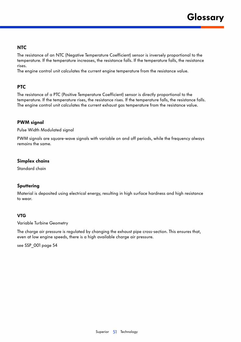
NTC
The resistance of an NTC (Negative Temperature Coefficient) sensor is inversely proportional to the temperature. If the temperature increases, the resistance falls. If the temperature falls, the resistance rises. The engine control unit calculates the current engine temperature from the resistance value.
PTC
The resistance of a PTC (Positive Temperature Coefficient) sensor is directly proportional to the temperature. If the temperature rises, the resistance rises. If the temperature falls, the resistance falls. The engine control unit calculates the current exhaust gas temperature from the resistance value.
PWM signal
Pulse Width Modulated signal
PWM signals are square-wave signals with variable on and off periods, while the frequency always remains the same.
Simplex chains
Standard chain
Sputtering
Material is deposited using electrical energy, resulting in high surface hardness and high resistance to wear.
VTG
Variable Turbine Geometry
The charge air pressure is regulated by changing the exhaust pipe cross-section. This ensures that, even at low engine speeds, there is a high available charge air pressure.
see SSP_001 page 54
Self-study program M002
© 2006 Volkswagen Marine
The texts, illustrations and standards in this Owner's Manual are based on theinformation available at the time of going to print. Reproduction, duplication andtranslation, in whole or in part, only with the express written permission of VolkswagenMarine. All copyrights and patent rights are expressly reserved by Volkswagen Marine.Subject to alterations.
Postfach 31 11 76, 38231 SalzgitterEdition 08/06 print number 065.991.T06.20
❀ This paper was produced from woodpulp bleached without chlorine.
Design and Operation
Self-study program M002
Bo
at
Eng
ines
fro
m
Vo
lksw
ag
en M
ari
ne
TDI 225-6Copy date 08/06
Related Documents