For maximum effectiveness and safety, please read these instructions completely before proceeding with installation. Failure to read these instructions can result in an incorrect installation. INSTALLATION GUIDE Kits 78560/78561 BMW M3/M4 3-bolt/5-bolt F80 F82 F83 Front Application MN-1038 • (011704) • ERN 8587

Welcome message from author
This document is posted to help you gain knowledge. Please leave a comment to let me know what you think about it! Share it to your friends and learn new things together.
Transcript

For maximum effectiveness and safety, please read these instructions completely before proceeding with installation.
Failure to read these instructions can result in an incorrect installation.
INSTALLATION GUIDE
Kits 78560/78561BMW M3/M4 3-bolt/5-bolt F80 F82 F83Front Application
MN
-103
8 •
(011
704)
• E
RN
858
7

2 MN-1038
Air Lift Performance

1MN-1038
Air Lift Performance
TABLE OF CONTENTS
A. Introduction . . . . . . . . . . . . . . . . . . . . . . . . . . . . . . . . . . . . . . 2 Notation Explanation . . . . . . . . . . . . . . . . . . . . . . . . . . . . . . . . . . . . . . . . . . . . . . . . .2
B. Important Safety Notices . . . . . . . . . . . . . . . . . . . . . . . . . . 2
C. Installation Diagram . . . . . . . . . . . . . . . . . . . . . . . . . . . . . . . 3 Hardware List . . . . . . . . . . . . . . . . . . . . . . . . . . . . . . . . . . . . . . . . . . . . . . . . . . . . . . .3
D. Installing the Air Suspension . . . . . . . . . . . . . . . . . . . . . . . . 4 Removing the Suspension . . . . . . . . . . . . . . . . . . . . . . . . . . . . . . . . . . . . . . . . . . . . .4 Installing the Kit Components . . . . . . . . . . . . . . . . . . . . . . . . . . . . . . . . . . . . . . . . . .7 Routing the Air Lines . . . . . . . . . . . . . . . . . . . . . . . . . . . . . . . . . . . . . . . . . . . . . . . . .9
E. Tips for Installing the Air Lines . . . . . . . . . . . . . . . . . . . . . 10 Cutting Air Lines . . . . . . . . . . . . . . . . . . . . . . . . . . . . . . . . . . . . . . . . . . . . . . . . . . . . 10 Push-to-Connect (PTC) Fittings . . . . . . . . . . . . . . . . . . . . . . . . . . . . . . . . . . . . . . . . 10 Checking for Leaks . . . . . . . . . . . . . . . . . . . . . . . . . . . . . . . . . . . . . . . . . . . . . . . . . . 10 Fixing Leaks . . . . . . . . . . . . . . . . . . . . . . . . . . . . . . . . . . . . . . . . . . . . . . . . . . . . . . . 10
F. Before Operating . . . . . . . . . . . . . . . . . . . . . . . . . . . . . . . . 11 Setting the Ride Height . . . . . . . . . . . . . . . . . . . . . . . . . . . . . . . . . . . . . . . . . . . . . . . 11 Torque Specifications . . . . . . . . . . . . . . . . . . . . . . . . . . . . . . . . . . . . . . . . . . . . . . . . 11 Suggested Driving Air Pressure and Maximum Air Pressure . . . . . . . . . . . . . . . . . . 11 Check for Binding . . . . . . . . . . . . . . . . . . . . . . . . . . . . . . . . . . . . . . . . . . . . . . . . . . . 12 Damping Adjustment . . . . . . . . . . . . . . . . . . . . . . . . . . . . . . . . . . . . . . . . . . . . . . . . 12 Aligning the Vehicle . . . . . . . . . . . . . . . . . . . . . . . . . . . . . . . . . . . . . . . . . . . . . . . . . . 12 Adjusting Extended or Drop Height Using Lower Mount . . . . . . . . . . . . . . . . . . . . . 13 Installation Checklist . . . . . . . . . . . . . . . . . . . . . . . . . . . . . . . . . . . . . . . . . . . . . . . . . 14 Post-installation Checklist . . . . . . . . . . . . . . . . . . . . . . . . . . . . . . . . . . . . . . . . . . . . 14
G. Use, Maintenance and Servicing . . . . . . . . . . . . . . . . . . . . 15 Tuning the Air Pressure . . . . . . . . . . . . . . . . . . . . . . . . . . . . . . . . . . . . . . . . . . . . . . . 15 Troubleshooting Guide . . . . . . . . . . . . . . . . . . . . . . . . . . . . . . . . . . . . . . . . . . . . . . . 15
Limited Warranty and Return Policy . . . . . . . . . . . . . . . . . 17
Replacement Part Information . . . . . . . . . . . . . . . . . . . . . 17
Contact Information . . . . . . . . . . . . . . . . . . . . . . . . . . . . . . 17

2 MN-1038
Air Lift Performance
DANGER
CAUTION
WARNING
CAUTION
WARNING
Air Lift Performance
A. Introduction
NOTE
Air Lift Performance thanks you for purchasing the most complete, fully engineered high-performance air suspension made for the BMW M3/M4. Read these installation instructions to correctly and safely set up the vehicle for a #lifeonair.
Air Lift assumes that the installer has the mechanical knowledge and ability to work on vehicle suspension systems and has basic tools necessary to complete the project. Special tools needed to complete the installation are noted on the Installation Diagram page.
Air Lift reserves the right to make changes and improvements to its products and publications at any time. For the latest version of this manual, contact Air Lift Performance at (800) 248-0892 or visit www.airliftperformance.com.
An Air Lift Performance air management system is highly recommended for this product. Learn more at air-lift.co/productlines.
NOTATION EXPLANATIONHazard notations appear in various locations in this publication. Information which is highlighted by one of these notations must be observed to help minimize risk of personal injury or possible improper installation which may render the vehicle unsafe. Notes are used to help emphasize areas of procedural importance and provide helpful suggestions. The following definitions explain the use of these notations as they appear throughout this guide.
INDICATES IMMEDIATE HAZARDS WHICH WILL RESULT IN SEVERE PERSONAL INJURY OR DEATH.
INDICATES HAZARDS OR UNSAFE PRACTICES WHICH COULD RESULT IN SEVERE PERSONAL INJURY OR DEATH.
INDICATES HAZARDS OR UNSAFE PRACTICES WHICH COULD RESULT IN DAMAGE TO THE MACHINE OR MINOR PERSONAL INJURY.
Indicates a procedure, practice or hint which is important to highlight.
B. Important Safety NoticesDO NOT INFLATE AIR SPRINGS WHILE OFF OF THE VEHICLE. DAMAGE TO ASSEM-BLY MAY RESULT AND VOID WARRANTY.
DO NOT WELD TO OR MODIFY PERFORMANCE STRUTS/SHOCKS IN ANY WAY. DAMAGE TO UNIT MAY OCCUR AND WILL VOID WARRANTY.

3MN-1038
Air Lift Performance
Item Part # Description ............................. Qty A 35412 RF BMW M3/M4 3-bolt strut ........................... 1 B 35414 RF BMW M3/M4 5-bolt strut ........................... 1 C 35413 LF BMW M3/M4 3-bolt strut ............................ 1 D 35415 LF BMW M3/M4 5-bolt strut ............................ 1 E 20997 Leader hose, 1/4” ID ........................................ 2 F 21810 Union, 1/4” FNPT x 1/4” PTC .......................... 2 G 21987 Union, 1/4” FNPT x 3/8” PTC .......................... 2 H Right end link ................................................... 1 I Left end link ..................................................... 1 J Spanner wrench ............................................... 1
C. Installation Diagram
Missing or damaged parts? Call Air Lift customer service at (800) 248-0892 for a replacement part.STOP!
F OR G
Parts ListDESCRIPTIONP/N'SQTYITEM
ASM, STRUT, RF, M3/M4 (5BOLT)PR354141AASM, STRUT, LF, M3/M4 (5BOLT)PR354151B
LEADER HOSE, 1/4" ID20997 C2CUN, 1/4" FNPT X 1/4" PTC, DOT218102DUN, 1/4" FNPT X 3/8" PTC, DOT219872E
M50 SPANNER1HEND LINK - BMW M4 RF1FEND LINK - BMW M4 LF1G
I
H
E
J
C OR D
A OR B
HARDWARE LIST
fig. C.1
4 MN-1038
Air Lift Performance
See important safety notices on page 2.NOTE
D. Installing the Air Suspension
1. In the engine compartment, remove the cowl covers and rubber strut mount covers from both sides of the car (Fig. D.1).
2. Loosen and remove the nine bolts on the carbon fiber cross brace including on the coolant overflow reservoir. Remove the brace (Fig. D.2).
3. Unclip the electronic damping control harness from the aluminum brace and separate it from the electrical connection. Unbolt the 17 bolts on the aluminum cross brace including the one for the coolant overflow reservoir. Two bolts are located under small covers at the base of the windshield in the middle. Vehicles with five-bolt upper strut mounts will have two additional bolts on each side. Remove the cross brace (Fig. D.3).
fig. D.1
REMOVING THE SUSPENSION
fig. D.3
fig. D.2
Repeat for the other side.

5MN-1038
Air Lift Performance
RAISE THE VEHICLE WITH A JACK AT THE APPROVED LIFTING POINTS AND USE JACK STANDS TO SUPPORT THE VEHICLE.
4. Remove the wheel, then remove the sway bar end link (Figs. D.4 & D.5).
5. Disconnect the electronic damping control on the side of the strut (Fig. D.6).
6. Disconnect the headlight alignment linkage from the lower control arm (Fig. D.7).
CAUTION
fig. D.4 fig. D.5
fig. D.6
fig. D.7

6 MN-1038
Air Lift Performance
7. Support the hub and remove the lower strut mount nut and pull the brake line bracket from the strut (Figs. D.8 & D.9).
8. Slide the steering knuckle off of the strut body (Figs. D.10 & D.11).
9. Remove the upper strut mount bolts and remove the strut. Leave the mounting plate in place (Fig. D.12). Leave the damper control connector on the strut.
fig. D.10 fig. D.11
fig. D.12
fig. D.9fig. D.8
Three-bolt upper mount shown.
7MN-1038
Air Lift Performance
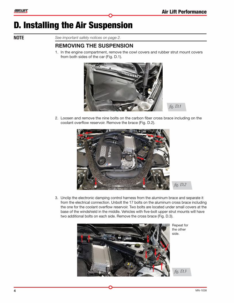
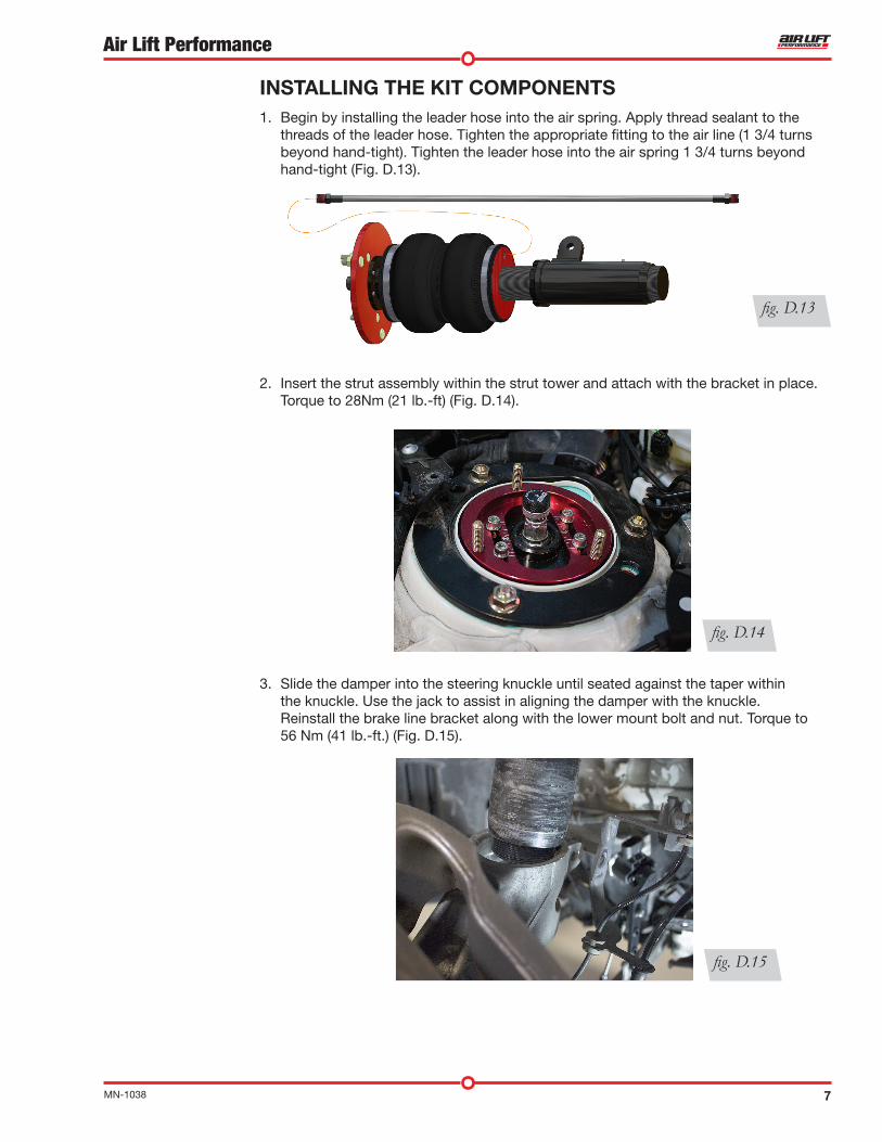
2. Insert the strut assembly within the strut tower and attach with the bracket in place. Torque to 28Nm (21 lb.-ft) (Fig. D.14).
3. Slide the damper into the steering knuckle until seated against the taper within the knuckle. Use the jack to assist in aligning the damper with the knuckle. Reinstall the brake line bracket along with the lower mount bolt and nut. Torque to 56 Nm (41 lb.-ft.) (Fig. D.15).
fig. D.14
INSTALLING THE KIT COMPONENTS1. Begin by installing the leader hose into the air spring. Apply thread sealant to the
threads of the leader hose. Tighten the appropriate fitting to the air line (1 3/4 turns beyond hand-tight). Tighten the leader hose into the air spring 1 3/4 turns beyond hand-tight (Fig. D.13).
fig. D.13
fig. D.15
8 MN-1038
Air Lift Performance
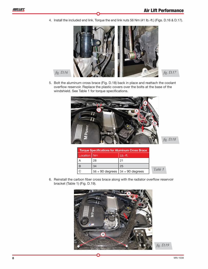
4. Install the included end link. Torque the end link nuts 56 Nm (41 lb.-ft.) (Figs. D.16 & D.17).
5. Bolt the aluminum cross brace (Fig. D.18) back in place and reattach the coolant overflow reservoir. Replace the plastic covers over the bolts at the base of the windshield. See Table 1 for torque specifications.
6. Reinstall the carbon fiber cross brace along with the radiator overflow reservoir bracket (Table 1) (Fig. D.19).
fig. D.16 fig. D.17
fig. D.19
Table 1
fig. D.18
C
B
A
A
Torque Specifications for Aluminum Cross Brace
Location Nm Lb.-ft.
A 28 21
B 34 25
C 56 + 90 degrees 34 + 90 degrees
A
A

9MN-1038
Air Lift Performance
7. Reinstall the cowl covers. The electronic damping control connectors are not used. The rubber strut mount cover can be put back in place.
8. Reconnect the headlight alignment linkage. Torque to 6Nm (53 lb.-in.) (Fig. D.7).
9. Fig. D.20 shows the finished installation.
ROUTING THE AIR LINES1. Fully compress the suspension using a jack. With the suspension compressed, review the
best routing for the leader hose that is clear of all suspension and steering components.
2. Routing should allow for the suspension to extend and steer without kinking, pulling the line tight or rubbing on other components. Following the brake line routing is often a good place to start. Check clearances to all other components.
fig. D.20

10 MN-1038
Air Lift Performance
E. Tips for Installing the Air Lines
CHECKING FOR LEAKS1. Inflate the air spring to 75-90 PSI.
2. Spray all connections with a solution of 1/5 liquid dish soap and 4/5 water. Spot leaks easily by looking for bubbles in the soapy water.
3. After the test, deflate the springs to the minimum pressure required to restore the system to normal ride height.
4. Check the air pressure again after 24 hours. A 2-4 PSI loss after initial installation is normal. Retest for leaks if the loss is more than 5 PSI.
FIXING LEAKS1. If there is a problem with the push-to-connect fitting, remove the air line as
described above. Trim 1” off the end of the air line. Be sure the cut is clean and square (see Fig. E.1).
2. Reinsert the air line into the push-to-connect fitting as described above.
CUTTING AIR LINESWhen cutting air lines, use a sharp knife or a hose cutter and make clean, square cuts (Fig. E.1). Do not use scissors or wire cutters because these tools will deform the air line, causing it to leak around fittings. Do not cut the lines at an angle.
The minimum bend radius for 1/4" air line is 1". The minimum bend radius for 3/8" air line is 1.5". Do not bend the air line less than the minimum bend radius or side load the fitting connections. Air lines are to be installed straight into fittings.
Inspect the air line for scratches that run lengthwise prior to installation. Contact Air Lift customer service at (800) 248-0892 if the air line is damaged.
To watch a video demonstrating proper air line cutting, go to air-lift.co/cuttingairline
fig. E.1
fig. E.2STEP 3
STEP 1
PUSH-TO-CONNECT (PTC) FITTINGSAir lines should be pushed into the push-to-connect fittings firmly, with a slight side-to-side rotational twist. Check the connection by pulling on each line to verify a robust connection.
To release the air line from the connection (Fig. E.2), first release all air from the system. Push in on the air line (step 1), push the collar in (step 2), and with the collar depressed, pull the air line out of the fitting (step 3).
NOTE
Push-to-connect fitting
Collar
STEP 2
Air line
11MN-1038
Air Lift Performance
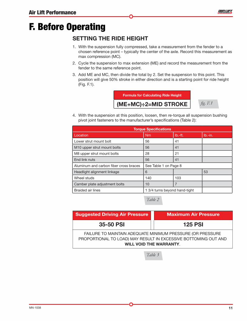
SETTING THE RIDE HEIGHT1. With the suspension fully compressed, take a measurement from the fender to a
chosen reference point – typically the center of the axle. Record this measurement as max compression (MC).
2. Cycle the suspension to max extension (ME) and record the measurement from the fender to the same reference point.
3. Add ME and MC, then divide the total by 2. Set the suspension to this point. This position will give 50% stroke in either direction and is a starting point for ride height (Fig. F.1).
4. With the suspension at this position, loosen, then re-torque all suspension bushing pivot joint fasteners to the manufacturer’s specifications (Table 2):
Formula for Calculating Ride Height
(ME+MC)÷2=MID STROKE
FAILURE TO MAINTAIN ADEQUATE MINIMUM PRESSURE (OR PRESSURE PROPORTIONAL TO LOAD) MAY RESULT IN EXCESSIVE BOTTOMING OUT AND
WILL VOID THE WARRANTY.
125 PSI
Maximum Air PressureSuggested Driving Air Pressure
F. Before Operating
fig. F.1
Table 3
Torque Specifications
Location Nm lb.-ft. lb.-in.
Lower strut mount bolt 56 41
M10 upper strut mount bolts 56 41
M8 upper strut mount bolts 28 21
End link nuts 56 41
Aluminum and carbon fiber cross braces See Table 1 on Page 8
Headlight alignment linkage 6 53
Wheel studs 140 103
Camber plate adjustment bolts 10 7
Braided air lines 1 3/4 turns beyond hand-tight
Table 2
35-50 PSI

12 MN-1038
Air Lift Performance
fig. F.3fig. F.2
ALIGNING THE VEHICLE1. Set the vehicle to the height at which it will most often be driven.
2. If the ride height is lower than stock, Air Lift Performance recommends loosening all pivot points (bolts, nuts) on any control arm, strut arm or radius rod that contains bushings. Once they have been loosened, re-torque to stock specifications (Table 1).
It may be necessary to cycle the suspension to loosen the bushing from its mount. This will help re-orient the bushing at its new position based on the chosen ride height.
3. Get a shop alignment of the vehicle at the new chosen ride height.
MAKE SURE THE FRONT WHEELS ARE STRAIGHT WHEN DEFLATING AND REIN-FLATING AIR BAGS.
CHECK FOR BINDING1. Inflate and deflate the system (do not exceed 125 PSI) to check for clearance or
binding issues. With the air springs deflated, check clearances on everything so as not to pinch brake lines, vent tubes, etc. Clear lines if necessary.
2. Inflate the air springs to 75-90 PSI and check all connections for leaks.
DAMPING ADJUSTMENT Suspension damping is a matter of compromise. Setting it too stiff will make the ride feel jarring. In addition, if the suspension is too stiff, the tires will lose contact with the road, reducing control and power delivery. On the other hand, if the suspension is too soft, the car can experience brake dive and excessive bouncing. The sweet spot lies somewhere in the middle. Air Lift dampers have a range of adjustment, which allows the driver to tune the ride and handling to his or her preferences.
Air Lift recommends damper and air pressure settings for every vehicle kit, but it is impossible to consider every situation. For example, even though Air Lift kits replace the dampers and springs, vehicles with sport-tuned suspensions might have stiffer bushings, larger anti-roll bars, bigger wheels, wider tires, etc. These settings may need to be adjusted to different vehicles and driving characteristics.
1. The dampers in this kit have 30 settings, or “clicks,” of adjustable compression and rebound damping characteristics. Damping is changed through the damper rod using the supplied adjuster (Figs. F.2 & F.3) or an 3mm hex key (not included).
2. Turn the adjuster clockwise (H) and the damping settings are hardened, reducing oscillations and body motion. Turn the adjuster counterclockwise (S) and the damping is softened.
3. Each damper in this kit is preset to “-26 clicks.” This means that the damper is adjusted 26 clicks away from full stiff, which starts at 0. Counting up from full stiff is the preferred method of keeping track of, or setting, damping. This setting was developed on a 2014 BMW M4 with stock suspension.
NOTE
CAUTION
13MN-1038
Air Lift Performance
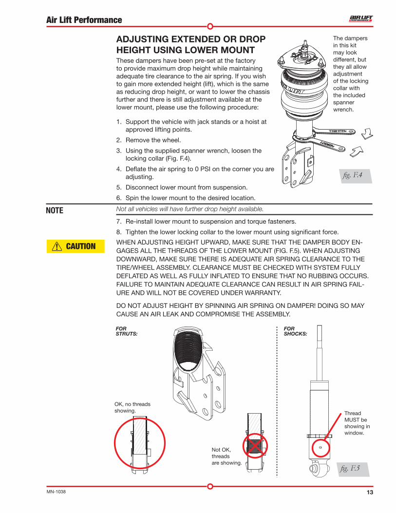
ADJUSTING EXTENDED OR DROP HEIGHT USING LOWER MOUNTThese dampers have been pre-set at the factory to provide maximum drop height while maintaining adequate tire clearance to the air spring. If you wish to gain more extended height (lift), which is the same as reducing drop height, or want to lower the chassis further and there is still adjustment available at the lower mount, please use the following procedure:
1. Support the vehicle with jack stands or a hoist at approved lifting points.
2. Remove the wheel.
3. Using the supplied spanner wrench, loosen the locking collar (Fig. F.4).
4. Deflate the air spring to 0 PSI on the corner you are adjusting.
5. Disconnect lower mount from suspension.
6. Spin the lower mount to the desired location.
Not all vehicles will have further drop height available.
7. Re-install lower mount to suspension and torque fasteners.
8. Tighten the lower locking collar to the lower mount using significant force.
WHEN ADJUSTING HEIGHT UPWARD, MAKE SURE THAT THE DAMPER BODY EN-GAGES ALL THE THREADS OF THE LOWER MOUNT (FIG. F.5). WHEN ADJUSTING DOWNWARD, MAKE SURE THERE IS ADEQUATE AIR SPRING CLEARANCE TO THE TIRE/WHEEL ASSEMBLY. CLEARANCE MUST BE CHECKED WITH SYSTEM FULLY DEFLATED AS WELL AS FULLY INFLATED TO ENSURE THAT NO RUBBING OCCURS. FAILURE TO MAINTAIN ADEQUATE CLEARANCE CAN RESULT IN AIR SPRING FAIL-URE AND WILL NOT BE COVERED UNDER WARRANTY.
DO NOT ADJUST HEIGHT BY SPINNING AIR SPRING ON DAMPER! DOING SO MAY CAUSE AN AIR LEAK AND COMPROMISE THE ASSEMBLY.
NOTE
The dampers in this kit may look different, but they all allow adjustment of the locking collar with the included spanner wrench.
fig. F.4
FOR STRUTS:
FOR SHOCKS:
Thread MUST be showing in window.
OK, no threads showing.
Not OK, threadsare showing.
fig. F.5
CAUTION

14 MN-1038
Air Lift Performance
Clearance — Inflate the air springs to 75-90 PSI and make sure there is at least 1/2” clearance from anything that might rub against the air spring. This should be checked with the air spring fully inflated and fully deflated.
Leak — Inflate the air springs to 75-90 PSI and check all connections for leaks. All leaks must be eliminated before the vehicle is road tested.
Heat — Be sure there is sufficient clearance from heat sources, at least 6” for air springs and air lines. If a heat shield was included in the kit, install it. If there is no heat shield, but one is required, call Air Lift customer service at (800) 248-0892.
Fastener — Recheck all bolts for proper torque.
Road — Inflate the springs to recommended driving pressures (Table 2). Drive the vehicle 10 miles and recheck for clearance, loose fasteners and air leaks.
Operating instructions — If professionally installed, the installer should review the operating instructions with the owner. Be sure to provide the owner with all paperwork that came with the kit.
INSTALLATION CHECKLIST
Overnight leak down test — Recheck air pressure 24 hours after installation and driving of the vehicle. If the pressure has dropped more than 5 PSI, there is a leak that must be fixed.
Air pressure requirements — It is important to understand the air pressure requirements of the air spring system. Regardless of load, the air pressure should always be adjusted to maintain adequate ride height at all times while driving.
Thirty-day or 500-mile test —Recheck the air spring system after 30 days or 500 miles, whichever comes first. If any part shows signs of rubbing or abrasion, the source should be identified and moved, if possible. If it is not possible to relocate the cause of the abrasion, the air spring may need to be remounted. If professionally installed, the installer should be consulted. Check all fasteners for tightness.
POST-INSTALLATION CHECKLIST
15MN-1038
Air Lift Performance
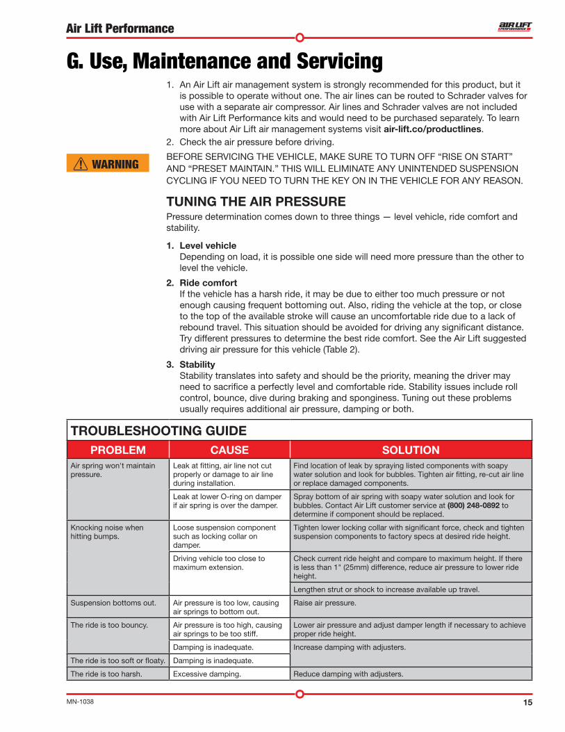
1. An Air Lift air management system is strongly recommended for this product, but it is possible to operate without one. The air lines can be routed to Schrader valves for use with a separate air compressor. Air lines and Schrader valves are not included with Air Lift Performance kits and would need to be purchased separately. To learn more about Air Lift air management systems visit air-lift.co/productlines.
2. Check the air pressure before driving.
BEFORE SERVICING THE VEHICLE, MAKE SURE TO TURN OFF “RISE ON START” AND “PRESET MAINTAIN.” THIS WILL ELIMINATE ANY UNINTENDED SUSPENSION CYCLING IF YOU NEED TO TURN THE KEY ON IN THE VEHICLE FOR ANY REASON.
TUNING THE AIR PRESSUREPressure determination comes down to three things — level vehicle, ride comfort and stability.
1. Level vehicle Depending on load, it is possible one side will need more pressure than the other to
level the vehicle.
2. Ride comfort If the vehicle has a harsh ride, it may be due to either too much pressure or not
enough causing frequent bottoming out. Also, riding the vehicle at the top, or close to the top of the available stroke will cause an uncomfortable ride due to a lack of rebound travel. This situation should be avoided for driving any significant distance. Try different pressures to determine the best ride comfort. See the Air Lift suggested driving air pressure for this vehicle (Table 2).
3. Stability Stability translates into safety and should be the priority, meaning the driver may
need to sacrifice a perfectly level and comfortable ride. Stability issues include roll control, bounce, dive during braking and sponginess. Tuning out these problems usually requires additional air pressure, damping or both.
G. Use, Maintenance and Servicing
WARNING
TROUBLESHOOTING GUIDEPROBLEM CAUSE SOLUTION
Air spring won't maintain pressure.
Leak at fitting, air line not cut properly or damage to air line during installation.
Find location of leak by spraying listed components with soapy water solution and look for bubbles. Tighten air fitting, re-cut air line or replace damaged components.
Leak at lower O-ring on damper if air spring is over the damper.
Spray bottom of air spring with soapy water solution and look for bubbles. Contact Air Lift customer service at (800) 248-0892 to determine if component should be replaced.
Knocking noise when hitting bumps.
Loose suspension component such as locking collar on damper.
Tighten lower locking collar with significant force, check and tighten suspension components to factory specs at desired ride height.
Driving vehicle too close to maximum extension.
Check current ride height and compare to maximum height. If there is less than 1" (25mm) difference, reduce air pressure to lower ride height.
Lengthen strut or shock to increase available up travel.
Suspension bottoms out. Air pressure is too low, causing air springs to bottom out.
Raise air pressure.
The ride is too bouncy. Air pressure is too high, causing air springs to be too stiff.
Lower air pressure and adjust damper length if necessary to achieve proper ride height.
Damping is inadequate. Increase damping with adjusters.
The ride is too soft or floaty. Damping is inadequate.
The ride is too harsh. Excessive damping. Reduce damping with adjusters.

16 MN-1038
Air Lift Performance
Notes

17MN-1038
Air Lift Performance
Replacement Part InformationIf replacement parts are needed, call Air Lift customer service. Most parts are immediately available and can be shipped the same day.
Contact Air Lift Company customer service at (800) 248-0892 first if:
• Parts are missing from the kit.
• Need technical assistance on installation or operation.
• Broken or defective parts in the kit.
• Wrong parts in the kit.
• Have a warranty claim or question.
Contact the retailer where the kit was purchased:
• If it is necessary to return or exchange the kit for any reason.
• If there is a problem with shipping if shipped from the retailer.
• If there is a problem with the price.
Contact InformationMailing address P.O. Box 80167 Lansing, MI 48908-0167
Shipping address 2727 Snow Road for returns Lansing, MI 48917
Phone Toll free: (800) 248-0892 International: (517) 322-2144
Email [email protected]
Web address www.airliftcompany.com
Limited Warranty and Return PolicyAir Lift Company provides a 1-year limited warranty to the original purchaser of Air Lift Performance damper kits from the date of original purchase, that the products will be free from defects in workmanship and materials when used on vehicles as specified by Air Lift Company and under normal operating conditions, subject to the requirements and exclusions set forth in the full Limited Warranty and Return Policy that is available online at www.airliftperformance.com/warranty.
For additional warranty information contact Air Lift Company customer service.
Air Lift Company reserves the right to make changes and improvements to its products and publications at any time. For the latest version of this manual, contact Air Lift Company at (800) 248-0892 or visit www.airliftperformance.com.

Need Help?Contact Air Lift Company customer service department by calling (800) 248-0892. For calls from outside the USA or Canada, dial (517) 322-2144.
Air Lift Performance • 2727 Snow Road • Lansing, MI 48917 or P.O. Box 80167 • Lansing, MI 48908-0167 Toll Free (800) 248-0892 • Local (517) 322-2144 • Fax (517) 322-0240 • www.airliftperformance.com
Thank you for purchasing Air Lift Performance products!
CONNECT BY SEARCHING FOR AIR LIFT PERFORMANCE #LIFEONAIR
Printed in the USA JJC-0517
Related Documents