[email protected] • ENGR-36_Lec-04_Force_Resultants-1.ppt 1 Bruce Mayer, PE Engineering-36: Engineering Mechanics - Statics Bruce Mayer, PE Licensed Electrical & Mechanical Engineer [email protected] Engineering 36 Chp 2: Force Resultants (1)

[email protected] ENGR-36_Lec-04_Force_Resultants-1.ppt 1 Bruce Mayer, PE Engineering-36: Engineering Mechanics - Statics Bruce Mayer, PE Licensed.
Jan 05, 2016
Welcome message from author
This document is posted to help you gain knowledge. Please leave a comment to let me know what you think about it! Share it to your friends and learn new things together.
Transcript
[email protected] • ENGR-36_Lec-04_Force_Resultants-1.ppt1
Bruce Mayer, PE Engineering-36: Engineering Mechanics - Statics
Bruce Mayer, PELicensed Electrical & Mechanical Engineer
Engineering 36
Chp 2: ForceResultants
(1)
[email protected] • ENGR-36_Lec-04_Force_Resultants-1.ppt2
Bruce Mayer, PE Engineering-36: Engineering Mechanics - Statics
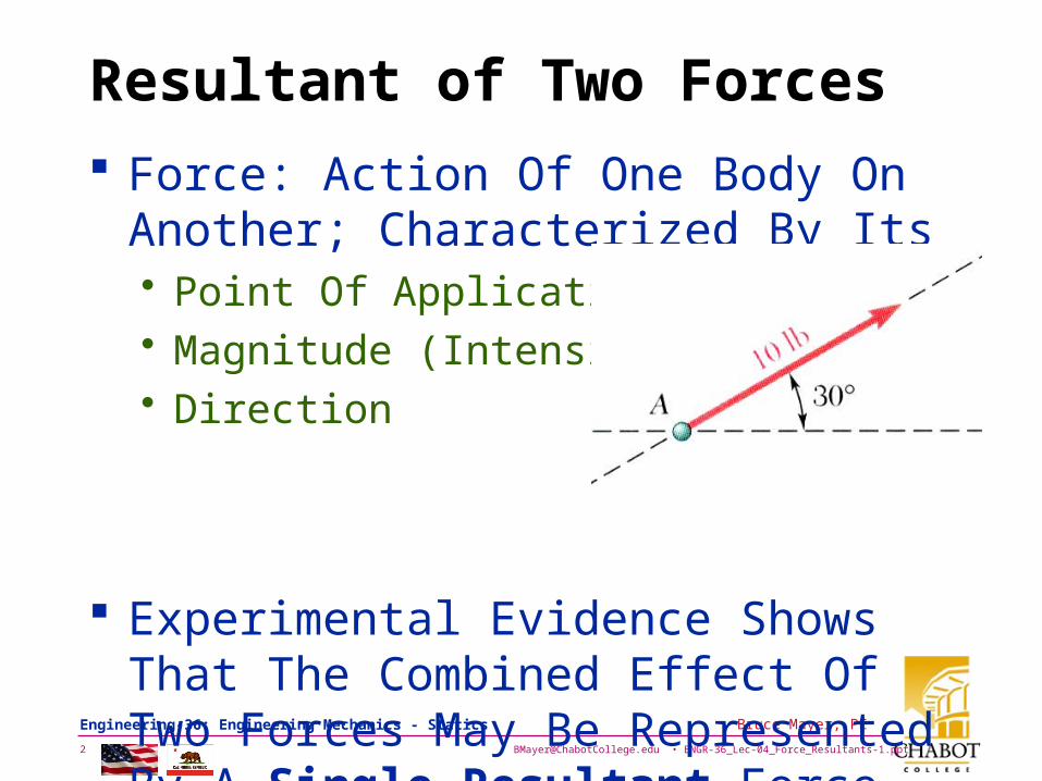
Resultant of Two Forces
Force: Action Of One Body OnAnother; Characterized By Its • Point Of Application• Magnitude (Intensity)• Direction
Experimental Evidence Shows That The Combined Effect Of Two Forces May Be Represented By A Single Resultant Force
[email protected] • ENGR-36_Lec-04_Force_Resultants-1.ppt3
Bruce Mayer, PE Engineering-36: Engineering Mechanics - Statics
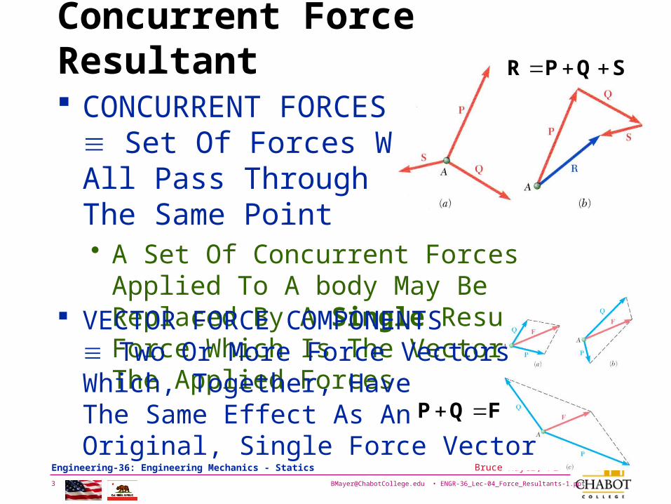
Concurrent Force Resultant
CONCURRENT FORCES Set Of Forces WhichAll Pass Through The Same Point• A Set Of Concurrent Forces Applied To A
body May Be Replaced By A Single Resultant Force Which Is The Vector Sum Of The Applied Forces
SQPR
FQP
VECTOR FORCE COMPONENTS Two Or More Force VectorsWhich, Together, HaveThe Same Effect As An Original, Single Force Vector
[email protected] • ENGR-36_Lec-04_Force_Resultants-1.ppt4
Bruce Mayer, PE Engineering-36: Engineering Mechanics - Statics
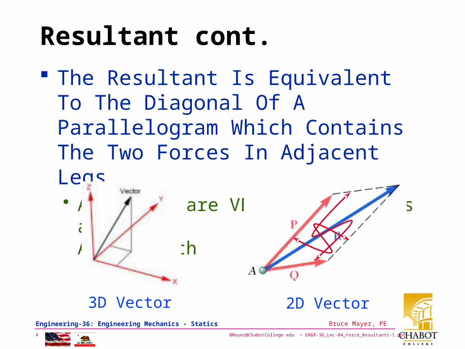
Resultant cont.
The Resultant Is Equivalent To The Diagonal Of A Parallelogram Which Contains The Two Forces In Adjacent Legs• As Forces are VECTOR Quantities and
they Add as Such
2D Vector3D Vector
[email protected] • ENGR-36_Lec-04_Force_Resultants-1.ppt5
Bruce Mayer, PE Engineering-36: Engineering Mechanics - Statics
Find the Force Resultant
Find the Resultant of multiple Forces by Vector Addition
The two basic forms of Vector addition• Decomposition
– Decompose all vectors into Axes Components– Combine Like Components to Obtain Resultant
• Graphical → Mag & Dir to SCALE– Tip-to-Tail (a.k.a. Head-to-Tail)– Parallelogram
[email protected] • ENGR-36_Lec-04_Force_Resultants-1.ppt6
Bruce Mayer, PE Engineering-36: Engineering Mechanics - Statics
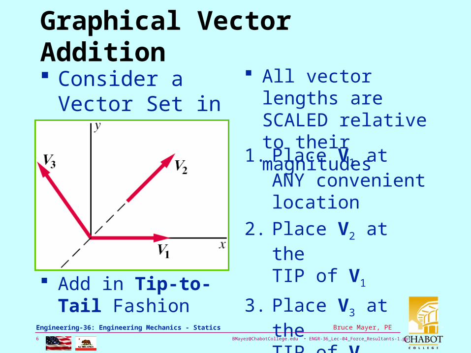
Graphical Vector Addition
Consider a Vector Set in the XY Plane:
All vector lengths are SCALED relative to their magnitudes
Add in Tip-to-Tail Fashion
1. Place V1 at ANY convenient location
2. Place V2 at the TIP of V1
3. Place V3 at the TIP of V2
[email protected] • ENGR-36_Lec-04_Force_Resultants-1.ppt7
Bruce Mayer, PE Engineering-36: Engineering Mechanics - Statics
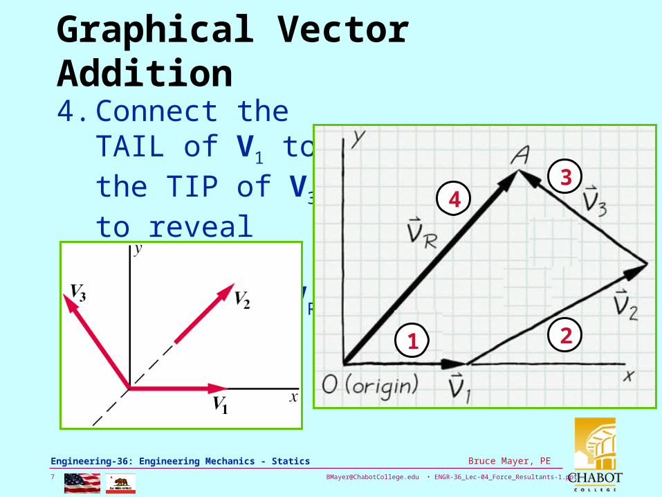
Graphical Vector Addition
4. Connect the TAIL of V1 to the TIP of V3 to reveal the RESULTANT, VR
1 2
34
[email protected] • ENGR-36_Lec-04_Force_Resultants-1.ppt8
Bruce Mayer, PE Engineering-36: Engineering Mechanics - Statics
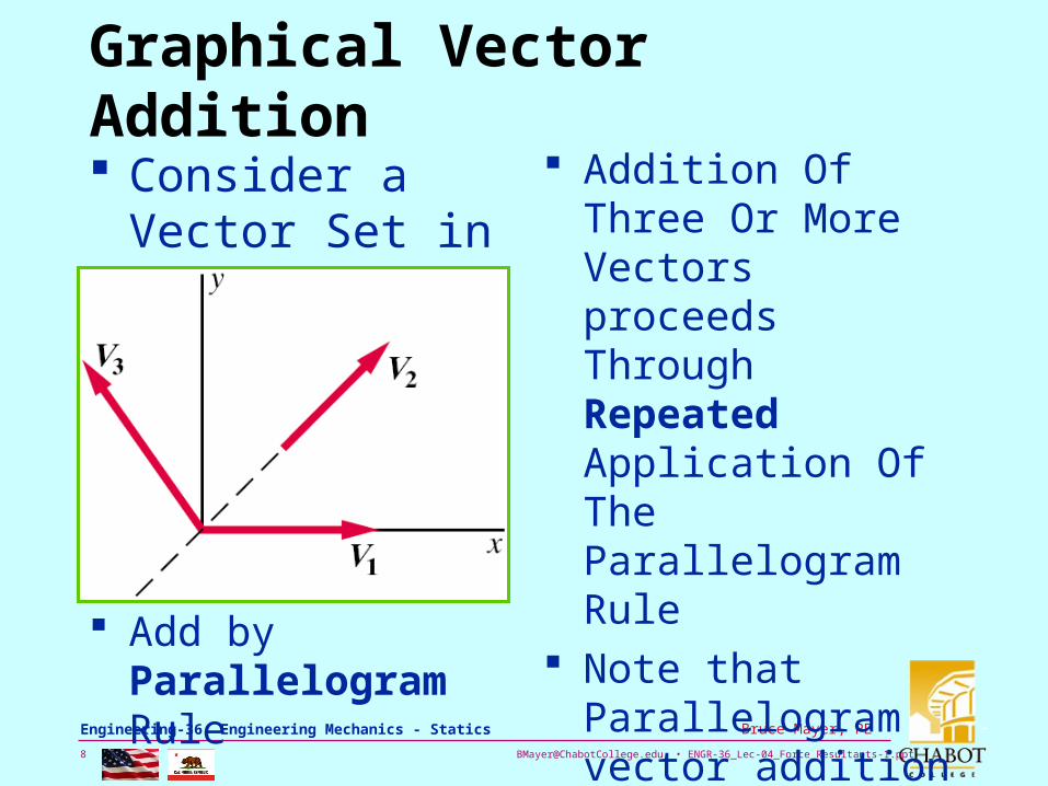
Graphical Vector Addition
Consider a Vector Set in the XY Plane:
Addition Of Three Or More Vectors proceeds Through RepeatedApplication Of The Parallelogram Rule
Note that Parallelogram vector addition proceeds in TAIL-to-TAIL fashion Add by
Parallelogram Rule

[email protected] • ENGR-36_Lec-04_Force_Resultants-1.ppt9
Bruce Mayer, PE Engineering-36: Engineering Mechanics - Statics
Graphical Vector Addition
1. Layout scaled vectors V1 & V2 in Tail-to-Tail Fashion
2. Draw a “Construction Line” (a.k.a. “XL”) from Tip of V1 that is Parallel (a.k.a. ||) to V2
3. Draw an XL from the tip of V2 that is || to V1. • The Two XL’s will
intersect if V1 & V2 are NOT Parallel
4. Connect the tail-pt of V1 & V2 to the XL intersection to reveal the intermediate, Vector, Vinter
[email protected] • ENGR-36_Lec-04_Force_Resultants-1.ppt10
Bruce Mayer, PE Engineering-36: Engineering Mechanics - Statics
Graphical Vector Addition
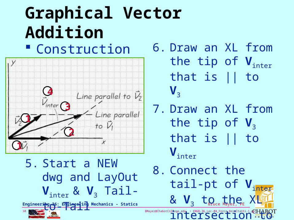
Construction of Vinter
5. Start a NEW dwg and LayOut Vinter & V3 Tail-to-Tail
12
3
4
1
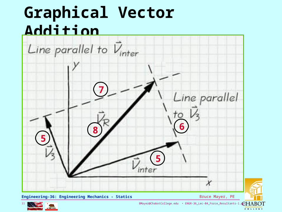
6. Draw an XL from the tip of Vinter that is || to V3
7. Draw an XL from the tip of V3 that is || to Vinter
8. Connect the tail-pt of Vinter & V3 to the XL intersection to reveal the Resultant Vector, VR
[email protected] • ENGR-36_Lec-04_Force_Resultants-1.ppt11
Bruce Mayer, PE Engineering-36: Engineering Mechanics - Statics
Graphical Vector Addition
5
6
7
85
[email protected] • ENGR-36_Lec-04_Force_Resultants-1.ppt12
Bruce Mayer, PE Engineering-36: Engineering Mechanics - Statics
Parallelogram Vector Addition
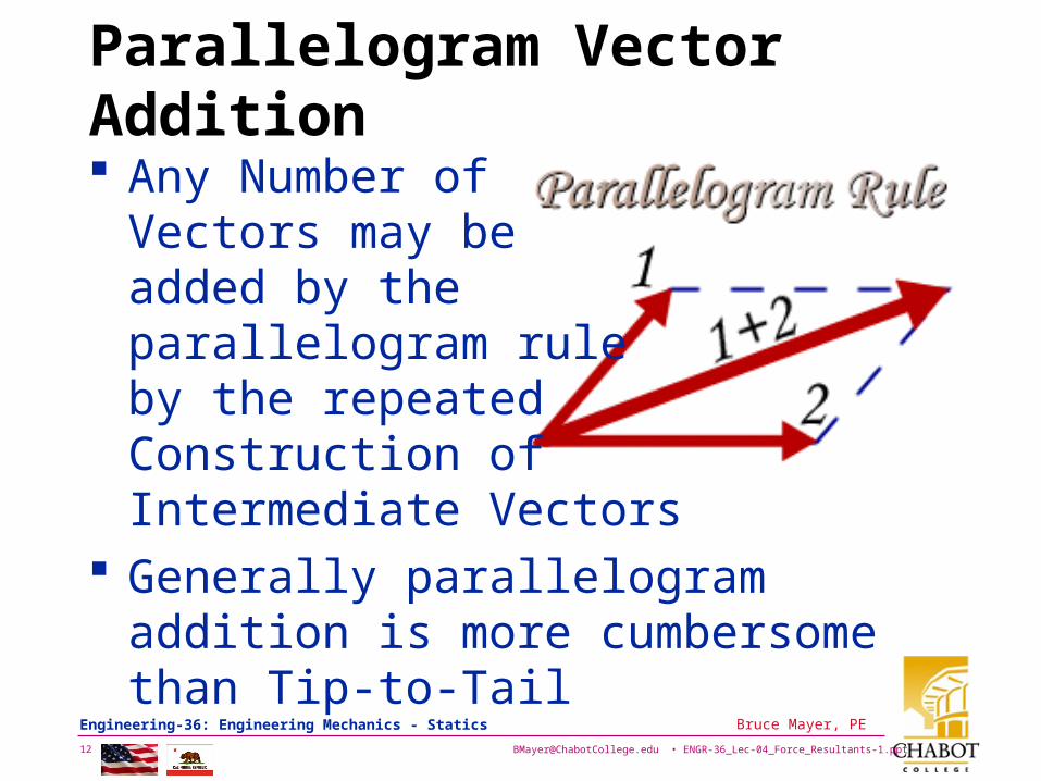
Any Number of Vectors may be added by the parallelogram ruleby the repeatedConstruction of Intermediate Vectors
Generally parallelogram addition is more cumbersome than Tip-to-Tail
[email protected] • ENGR-36_Lec-04_Force_Resultants-1.ppt13
Bruce Mayer, PE Engineering-36: Engineering Mechanics - Statics
Example: Graphical Force Add
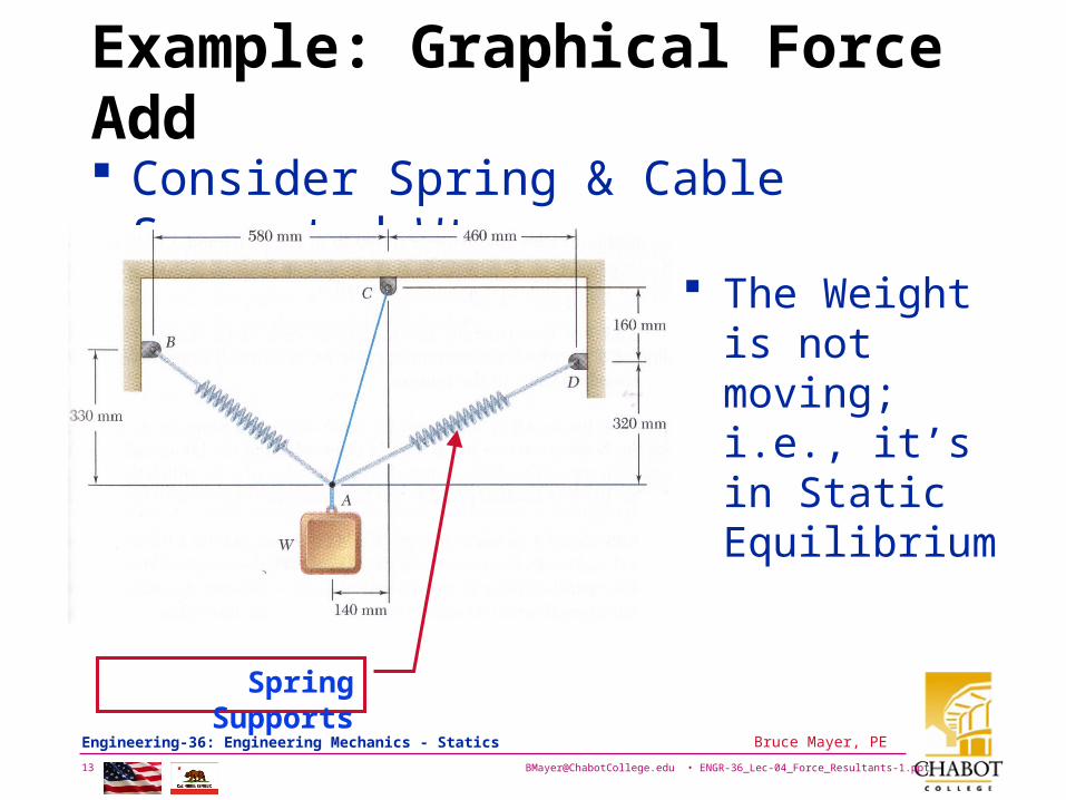
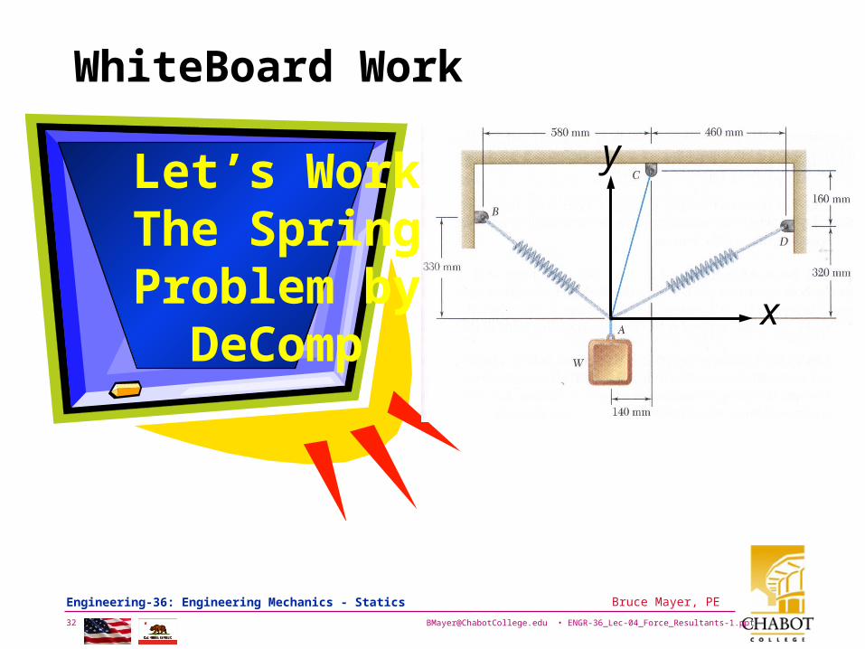
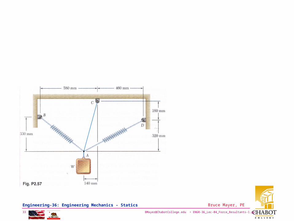
Consider Spring & Cable Supported Wt
Spring Supports
The Weight is not moving; i.e., it’s in Static Equilibrium
[email protected] • ENGR-36_Lec-04_Force_Resultants-1.ppt14
Bruce Mayer, PE Engineering-36: Engineering Mechanics - Statics
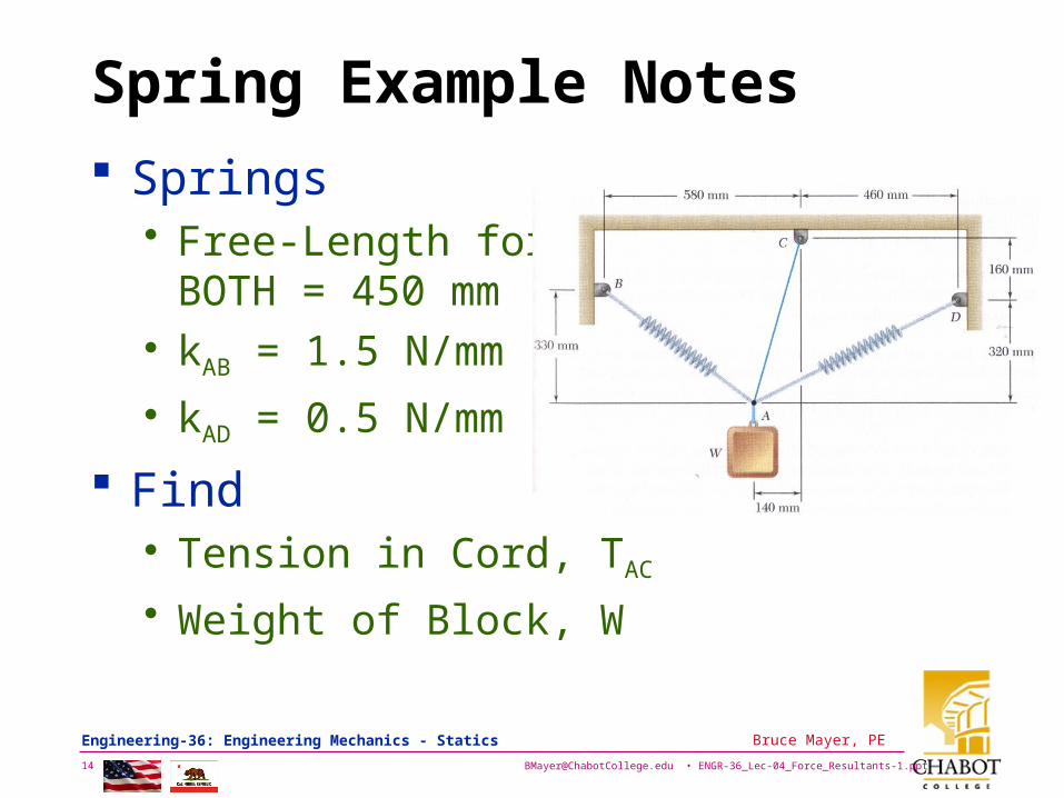
Spring Example Notes
Springs• Free-Length for
BOTH = 450 mm• kAB = 1.5 N/mm
• kAD = 0.5 N/mm
Find• Tension in Cord, TAC
• Weight of Block, W
[email protected] • ENGR-36_Lec-04_Force_Resultants-1.ppt15
Bruce Mayer, PE Engineering-36: Engineering Mechanics - Statics
Example: Solution Plan Use Spring Constants and Extension to
Find TAB & TAD
Draw Vector Force PolyGon Noting that the PolyGon Must Close for a system in Equilibrium
Draw Force/Vector PolyGon in Tip-to-Tail form to reveal TAC & W• Note that the Directions are known for W & TAC;
i.e., the Force LoA is CoIncident with Geometry
Solve by Hand & AutoCAD Scaling
[email protected] • ENGR-36_Lec-04_Force_Resultants-1.ppt16
Bruce Mayer, PE Engineering-36: Engineering Mechanics - Statics
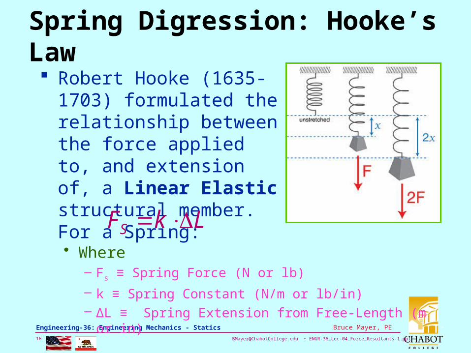
Spring Digression: Hooke’s Law Robert Hooke (1635-1703)
formulated the relationship between the force applied to, and extension of, a Linear Elastic structural member. For a Spring:
LkFS • Where
– Fs ≡ Spring Force (N or lb)
– k ≡ Spring Constant (N/m or lb/in)– ΔL ≡ Spring Extension from Free-Length (m or in)
[email protected] • ENGR-36_Lec-04_Force_Resultants-1.ppt17
Bruce Mayer, PE Engineering-36: Engineering Mechanics - Statics
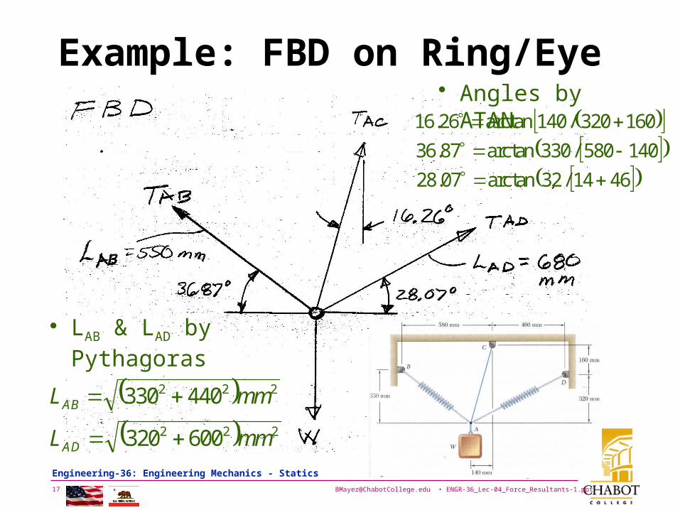
Example: FBD on Ring/Eye
222
222
600320
440330
mmL
mmL
AD
AB
• LAB & LAD by Pythagoras
• Angles by ATAN
4614/32arctan07.28
140580/330arctan87.36
160320/140arctan26.16
[email protected] • ENGR-36_Lec-04_Force_Resultants-1.ppt18
Bruce Mayer, PE Engineering-36: Engineering Mechanics - Statics
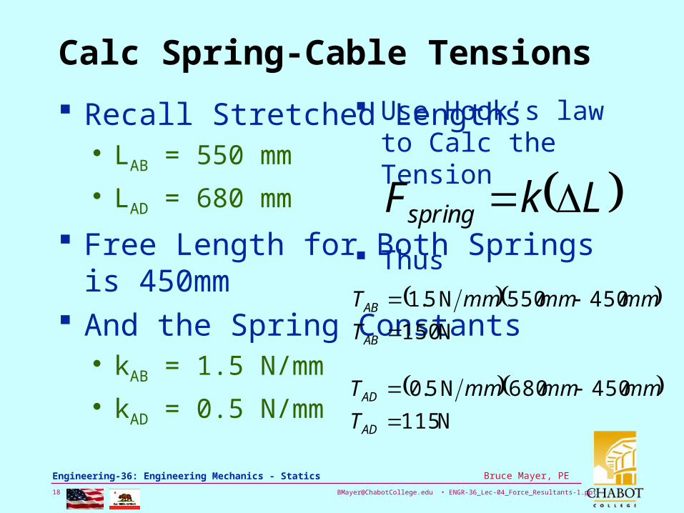
Calc Spring-Cable Tensions
Recall Stretched Lengths• LAB = 550 mm
• LAD = 680 mm
Free Length for Both Springs is 450mm And the Spring Constants
• kAB = 1.5 N/mm
• kAD = 0.5 N/mm
Use Hook’s law to Calc the Tension
N 150
450550N 5.1
AB
AB
T
mmmmmmT
LkFspring Thus
N 115
450680N 5.0
AD
AD
T
mmmmmmT

[email protected] • ENGR-36_Lec-04_Force_Resultants-1.ppt19
Bruce Mayer, PE Engineering-36: Engineering Mechanics - Statics
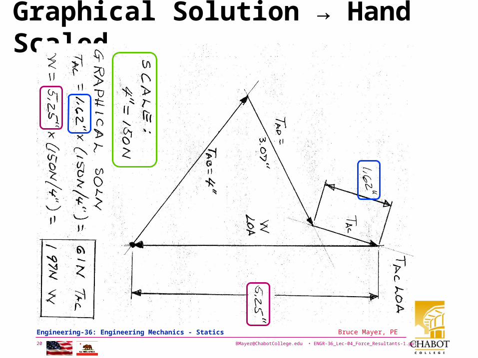
Graphical Solution Hand1. Select Scaling
Factor of 4in/150N
2. Draw Known Force TAB with Direction & Scaled-Mag
3. From Tip of TAB Draw Known Force TAD
4. Make XL’s for Known LoA’s For W and TAC
• XL for TAC LoA from Tip of TAD
• XL for W LoA from Tail of TAB
[email protected] • ENGR-36_Lec-04_Force_Resultants-1.ppt20
Bruce Mayer, PE Engineering-36: Engineering Mechanics - Statics
Graphical Solution → Hand Scaled
[email protected] • ENGR-36_Lec-04_Force_Resultants-1.ppt21
Bruce Mayer, PE Engineering-36: Engineering Mechanics - Statics
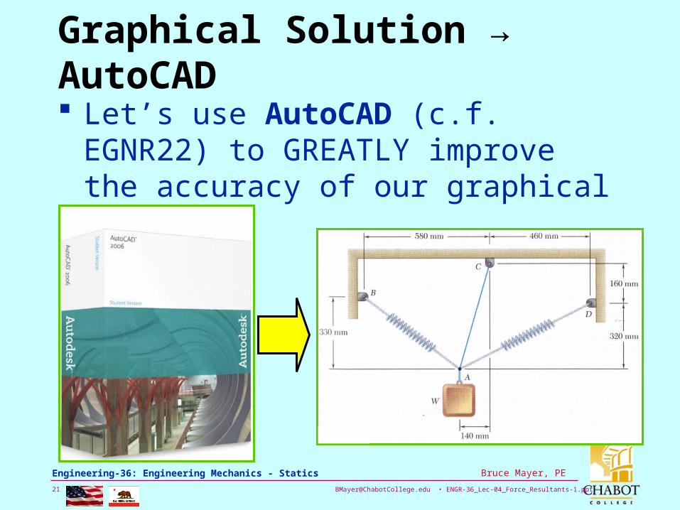
Graphical Solution → AutoCAD
Let’s use AutoCAD (c.f. EGNR22) to GREATLY improve the accuracy of our graphical Solution
[email protected] • ENGR-36_Lec-04_Force_Resultants-1.ppt22
Bruce Mayer, PE Engineering-36: Engineering Mechanics - Statics
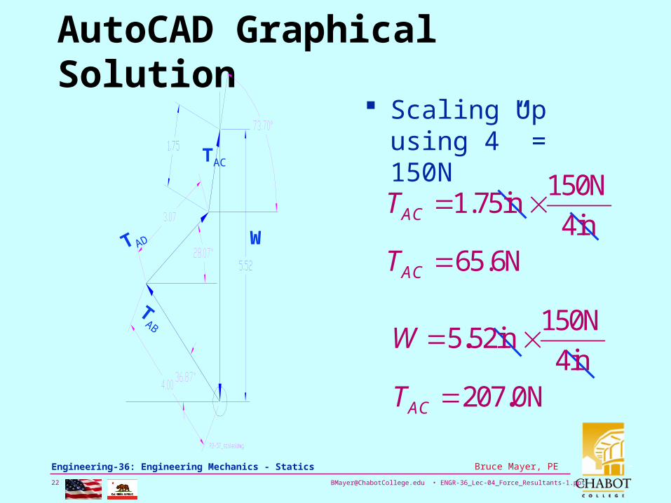
AutoCAD Graphical Solution
W
TAB
T AD
TAC
Scaling Up using 4” = 150N
65.6N4in
150N1.75in
AC
AC
T
T
N00724in
150Nin525
.
.
ACT
W

[email protected] • ENGR-36_Lec-04_Force_Resultants-1.ppt23
Bruce Mayer, PE Engineering-36: Engineering Mechanics - Statics
Compare: Hand vs. ACAD
Check the Pencil & Paper Solution to mathematically precise ACAD soln• TAC: 61/65.6 →
Hand Soln 9.3% Low
• W: 197/207 → 4.83% low
Not Bad for Engr Comp-Pad, Ruler, and Protractor
[email protected] • ENGR-36_Lec-04_Force_Resultants-1.ppt24
Bruce Mayer, PE Engineering-36: Engineering Mechanics - Statics
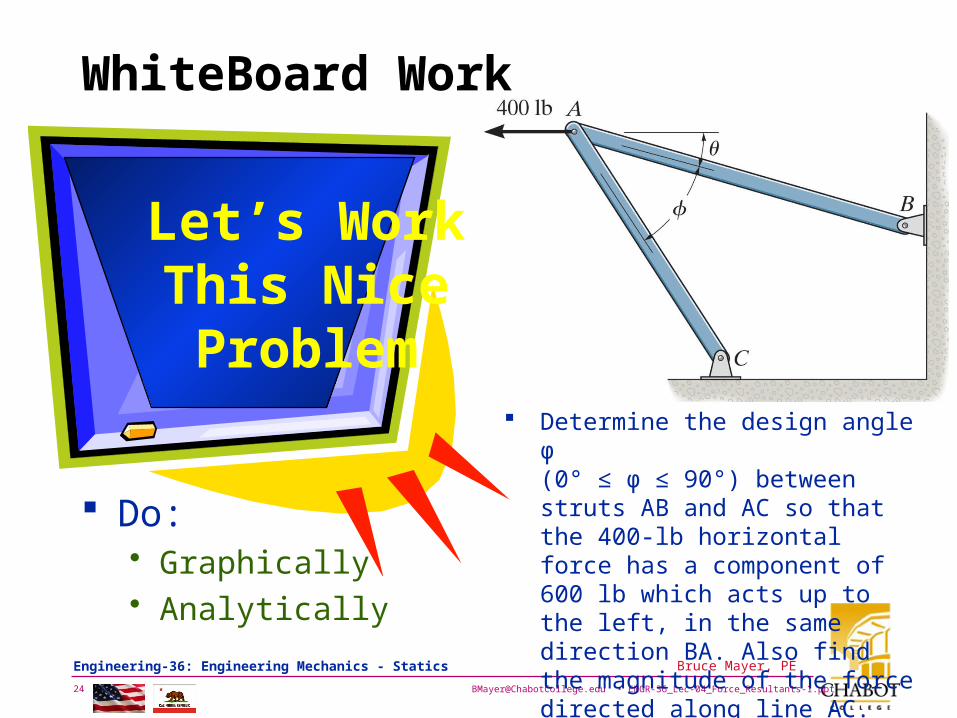
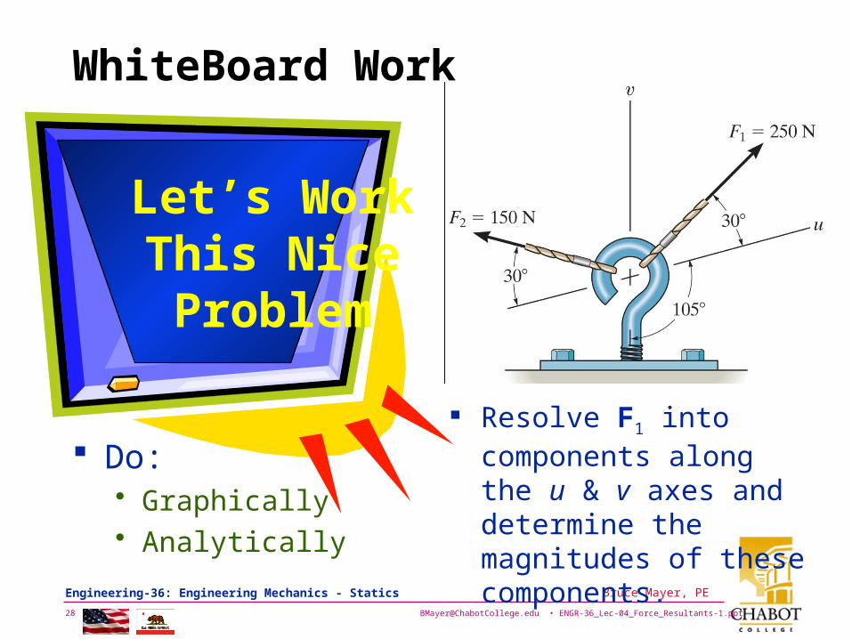
WhiteBoard Work
Let’s WorkThis NiceProblem
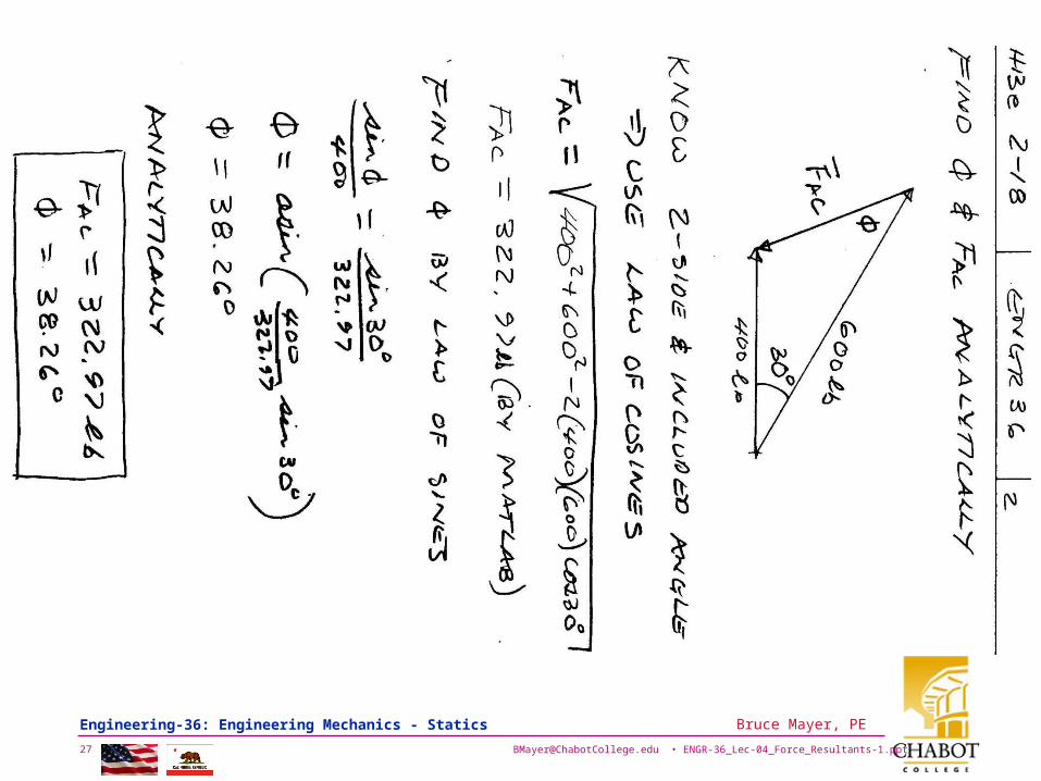
Determine the design angle φ (0° ≤ φ ≤ 90°) between struts AB and AC so that the 400-lb horizontal force has a component of 600 lb which acts up to the left, in the same direction BA. Also find the magnitude of the force directed along line AC. Take θ = 30°.
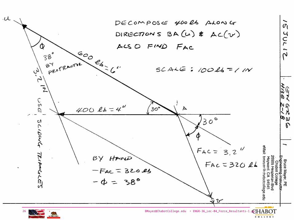
Do:• Graphically• Analytically
[email protected] • ENGR-36_Lec-04_Force_Resultants-1.ppt25
Bruce Mayer, PE Engineering-36: Engineering Mechanics - Statics
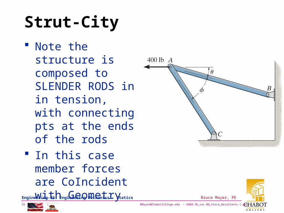
Strut-City Note the structure is
composed to SLENDER RODS in in tension, with connecting pts at the ends of the rods
In this case member forces are CoIncident with Geometry
[email protected] • ENGR-36_Lec-04_Force_Resultants-1.ppt26
Bruce Mayer, PE Engineering-36: Engineering Mechanics - Statics
[email protected] • ENGR-36_Lec-04_Force_Resultants-1.ppt27
Bruce Mayer, PE Engineering-36: Engineering Mechanics - Statics
[email protected] • ENGR-36_Lec-04_Force_Resultants-1.ppt28
Bruce Mayer, PE Engineering-36: Engineering Mechanics - Statics
WhiteBoard Work
Let’s WorkThis NiceProblem
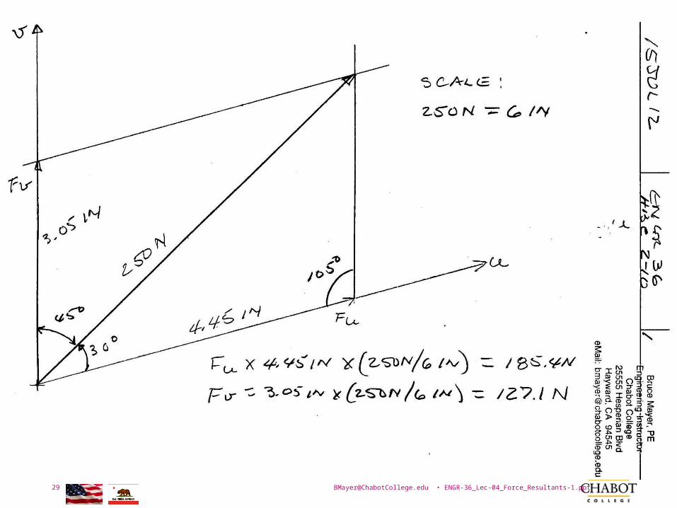
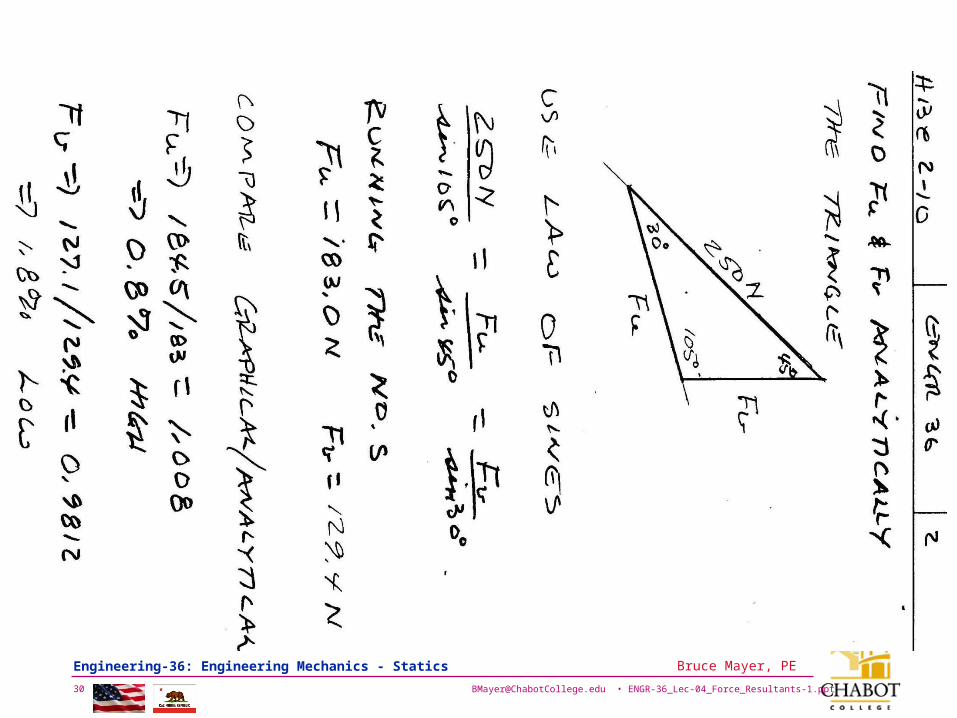
Resolve F1 into components along the u & v axes and determine the magnitudes of these components.
Do:• Graphically• Analytically
[email protected] • ENGR-36_Lec-04_Force_Resultants-1.ppt29
Bruce Mayer, PE Engineering-36: Engineering Mechanics - Statics
[email protected] • ENGR-36_Lec-04_Force_Resultants-1.ppt30
Bruce Mayer, PE Engineering-36: Engineering Mechanics - Statics
[email protected] • ENGR-36_Lec-04_Force_Resultants-1.ppt31
Bruce Mayer, PE Engineering-36: Engineering Mechanics - Statics
Bruce Mayer, PERegistered Electrical & Mechanical Engineer
Engineering 36
Appendix
[email protected] • ENGR-36_Lec-04_Force_Resultants-1.ppt32
Bruce Mayer, PE Engineering-36: Engineering Mechanics - Statics
WhiteBoard Work
Let’s WorkThe SpringProblem by
DeCompx
y
[email protected] • ENGR-36_Lec-04_Force_Resultants-1.ppt33
Bruce Mayer, PE Engineering-36: Engineering Mechanics - Statics
Related Documents


