Blood Pressure • An Individuals blood pressure is a standard clinical measurement • Is considered a good indicator of the status of the cardiovascular system. • Blood pressure values in the various chambers of the heart and in the peripheral vascular system help the physician determine the functional integrity of the cardio vascular system.

Blood Pressure
Jan 19, 2016
An Individuals blood pressure is a standard clinical measurement Is considered a good indicator of the status of the cardiovascular system. - PowerPoint PPT Presentation
Welcome message from author
This document is posted to help you gain knowledge. Please leave a comment to let me know what you think about it! Share it to your friends and learn new things together.
Transcript
Blood Pressure
• An Individuals blood pressure is a standard clinical measurement
• Is considered a good indicator of the status of the cardiovascular system.
• Blood pressure values in the various chambers of the heart and in the peripheral vascular system help the physician determine the functional integrity of the cardio vascular system.
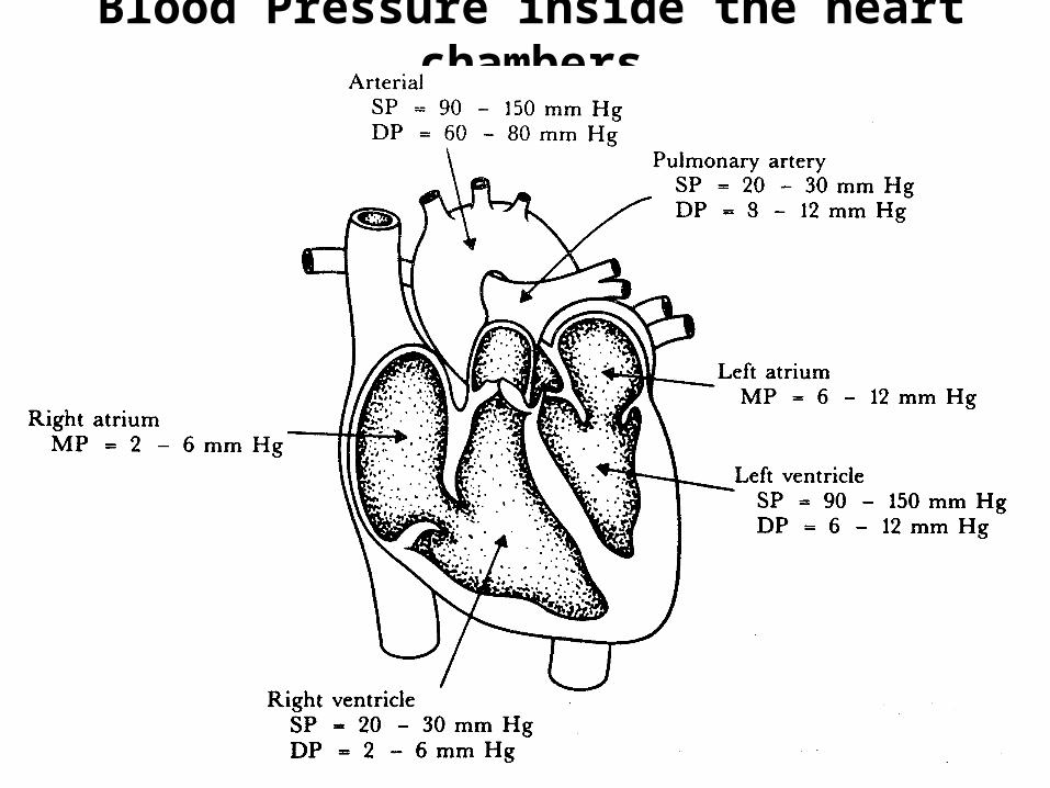
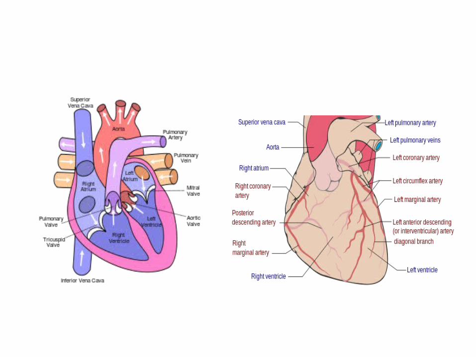
Blood Pressure inside the heart chambers

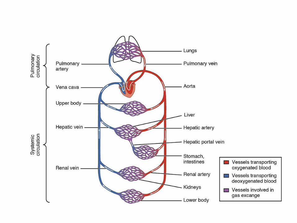
Major Arteries & Veins of the Body

Cardiovascular system-typical values

Blood Pressure Measurement• Direct (invasive)
1. Extravascular Method• The vascular pressure is coupled to an external sensor
element via a liquid filled catheter.
[Catheter – is a long tube introduced into the heart or a major vessel by way of a superficial vein or artery.]
2. Intravascular• A sensor is placed into the tip of a catheter that is placed in
the vascular system.
• Indirect (non invasive)• SphygmomanometerConsists of an inflatable pressure cuff and a manometer to measure the pressure in the cuff.
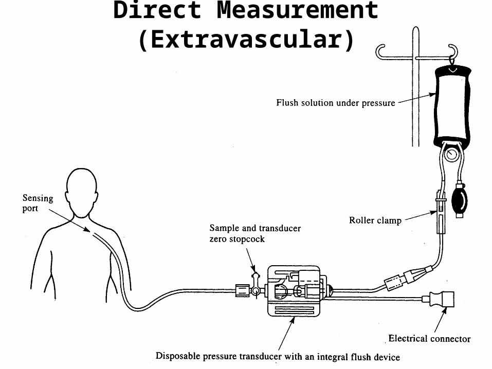
Direct Measurement(Extravascular)

Disposable blood-pressure sensor with integral flush device
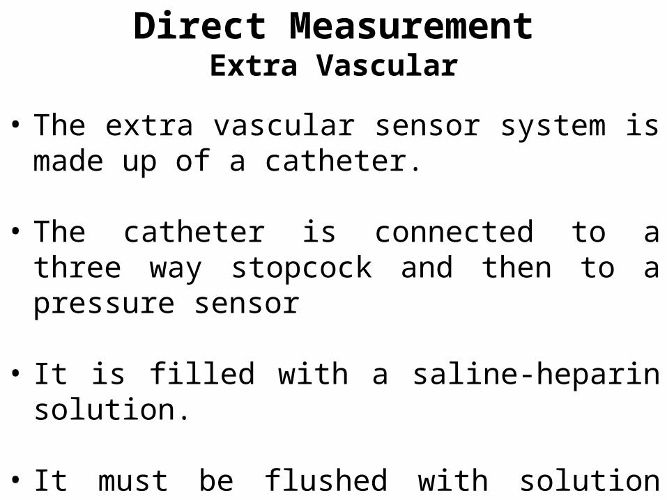
Direct MeasurementExtra Vascular
• The extra vascular sensor system is made up of a catheter.
• The catheter is connected to a three way stopcock and then to a pressure sensor
• It is filled with a saline-heparin solution.
• It must be flushed with solution every few minutes to prevent blood clotting at the tip.
• Physician inserts the catheter
• Either by means of a surgical cut-down, which exposes the artery or vein.
• or by means of percutaneous insertion which involves the use of a special needle or guide-wire technique.
• Blood pressure is transmitted via the catheter column to the sensor and finally to the diaphragm which is deflected.
• The displacement of the diaphragm is sensed electronically.
Direct MeasurementExtra Vascular contd…
• Disadvantages
• The frequency response of the catheter-sensor system is limited by the hydraulic properties of the system.
• Creates time delay in detection of pressures when a pressure pulse is transmitted.
Direct MeasurementExtra Vascular contd…
• The sensor is placed at the tip of the catheter.
• Enables the physician to obtain a high frequency response in detection of pressures at the tip of the catheter.
• Types of sensors1. Strain-gage systems • bonded onto a flexible diaphragm at the catheter tip.
2. Fibre-optic device• Measures the displacement of the diaphragm optically by
varying reflection of light from the back of the deflecting diaphragm.
Direct MeasurementIntravascular
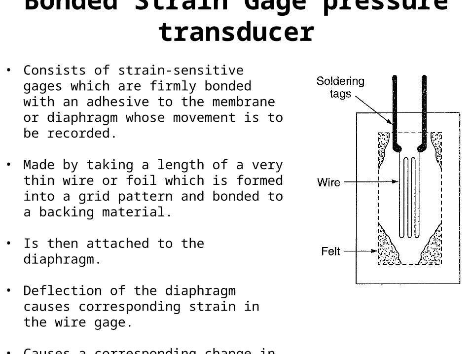
Bonded Strain Gage pressure transducer
• Consists of strain-sensitive gages which are firmly bonded with an adhesive to the membrane or diaphragm whose movement is to be recorded.
• Made by taking a length of a very thin wire or foil which is formed into a grid pattern and bonded to a backing material.
• Is then attached to the diaphragm.
• Deflection of the diaphragm causes corresponding strain in the wire gage.
• Causes a corresponding change in the resistance which is proportional to the pressure.
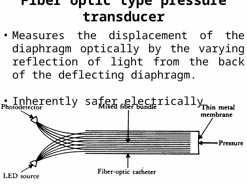
Fiber optic type pressure transducer
• Measures the displacement of the diaphragm optically by the varying reflection of light from the back of the deflecting diaphragm.
• Inherently safer electrically
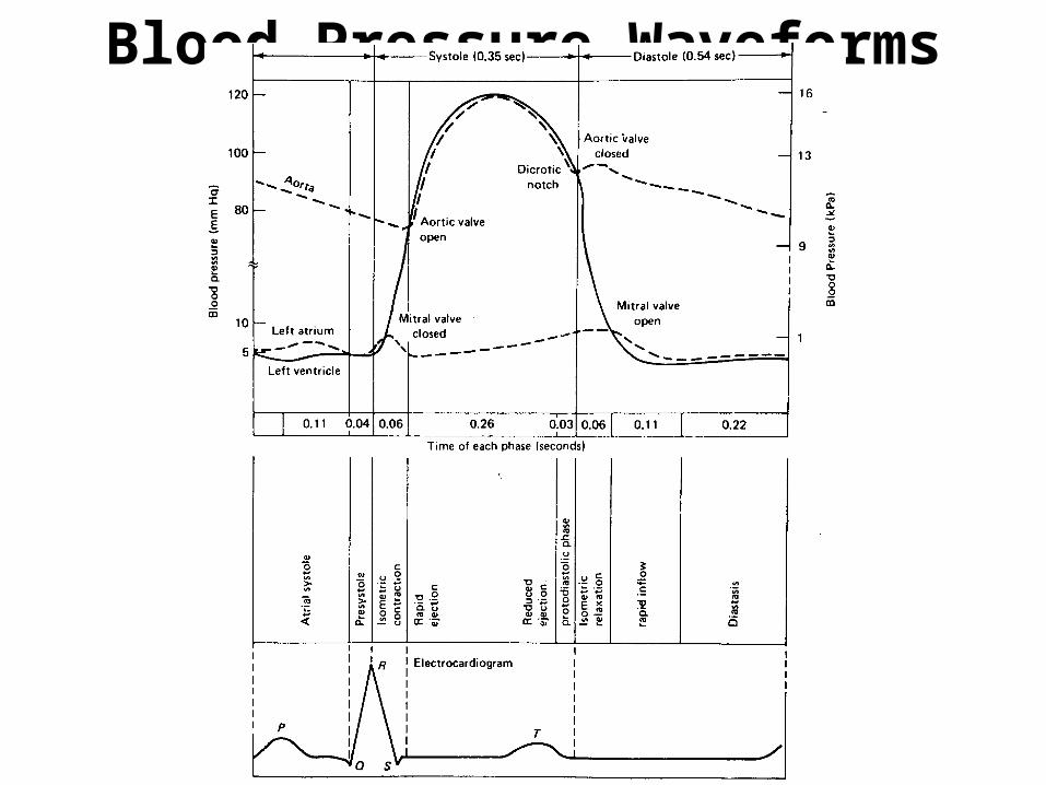
Blood Pressure Waveforms
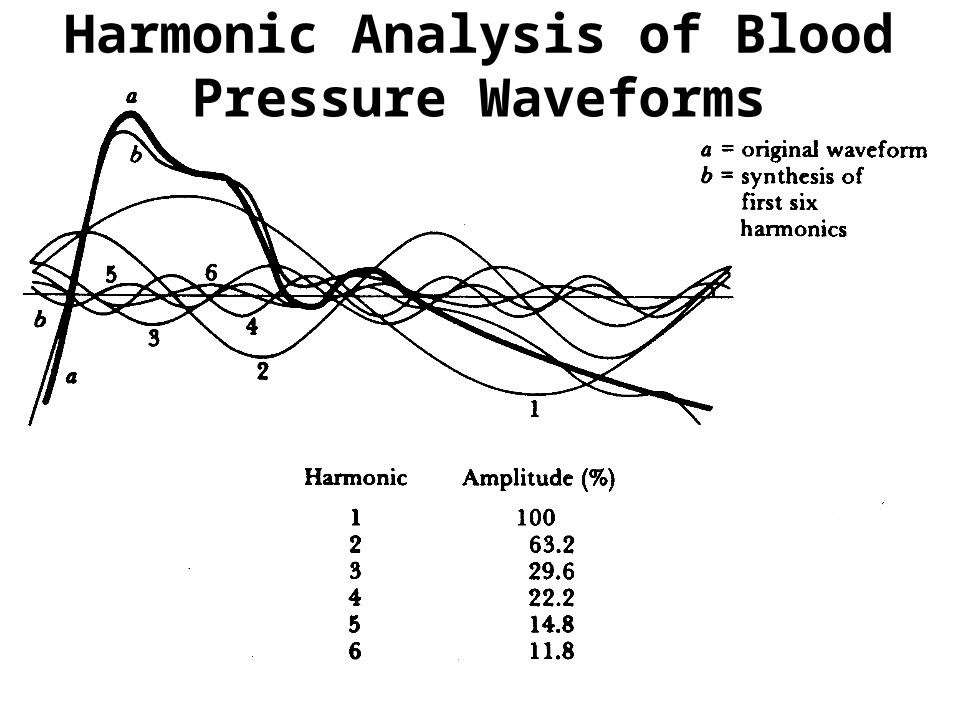
Harmonic Analysis of Blood Pressure Waveforms
Harmonic Analysis of Blood Pressure Waveforms
• Using Fourier Analysis techniques in the quantification of pressure and flow.
• Blood pressure pulse can be divided into its fundamental component (of the same frequency as the blood pressure wave) and its significant harmonics.
• Analysis of the frequency components of the pulse yield more information on arterial properties.
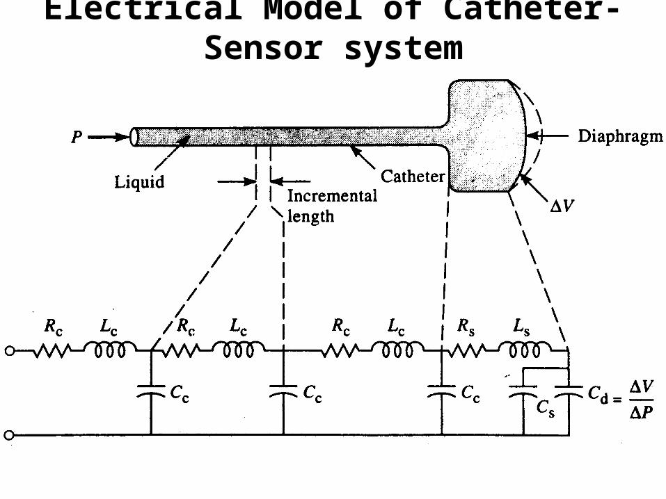
Electrical Model of Catheter-Sensor system

Testing technique for measuring the transient response of the catheter-sensor system

Transient response of the catheter-sensor system
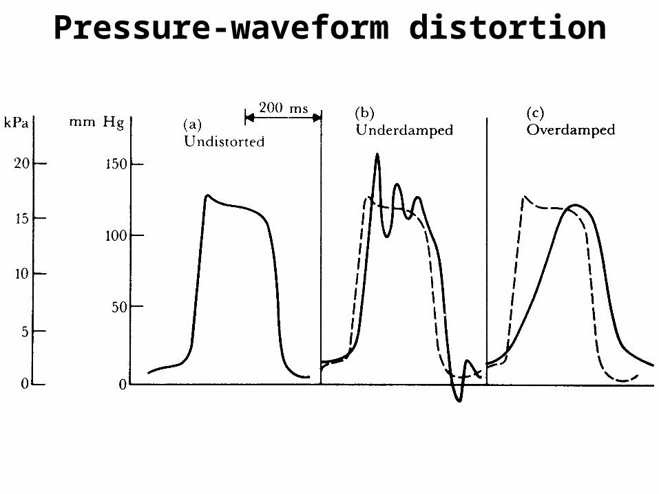
Pressure-waveform distortion
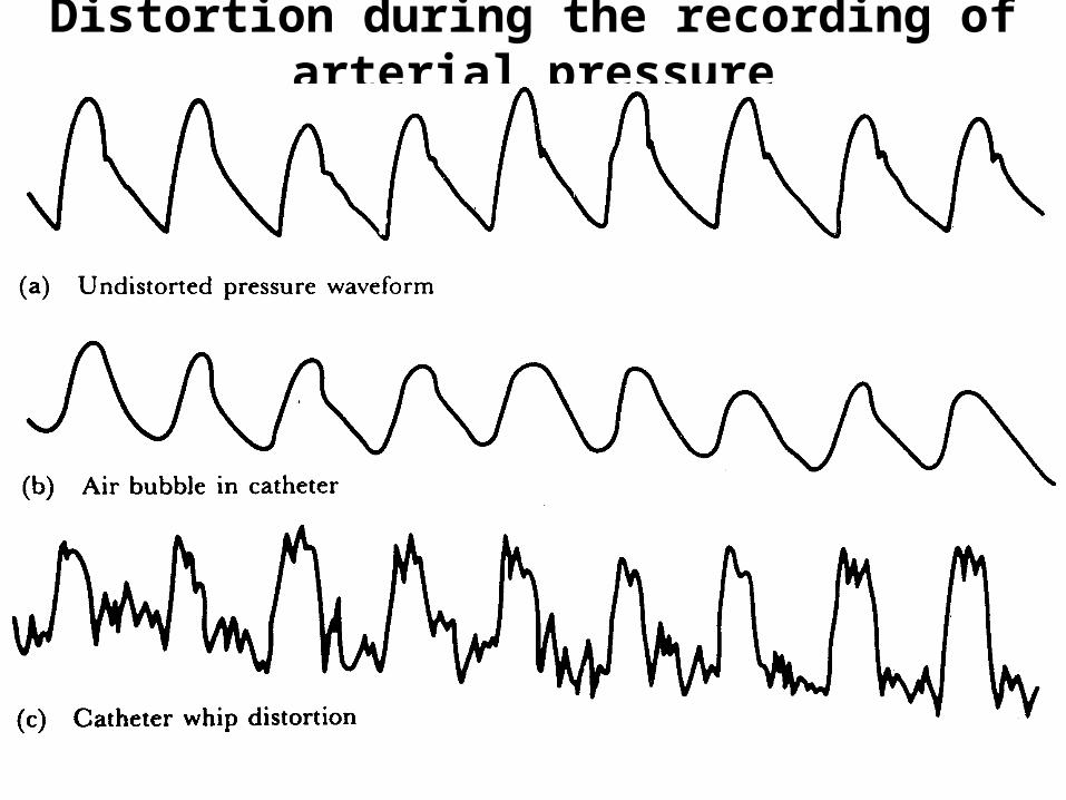
Distortion during the recording of arterial pressure
• For determining the function of• Capillary bed• Right side of the heart
• The central venous pressure is measured in the central vein or in the right atrium.
• It fluctuates above and below atmospheric pressure as the subject breathes.
• The reference level for venous pressure is at the right atrium.
• Central venous pressure is an important indicator of myocardial performance
Venous pressure
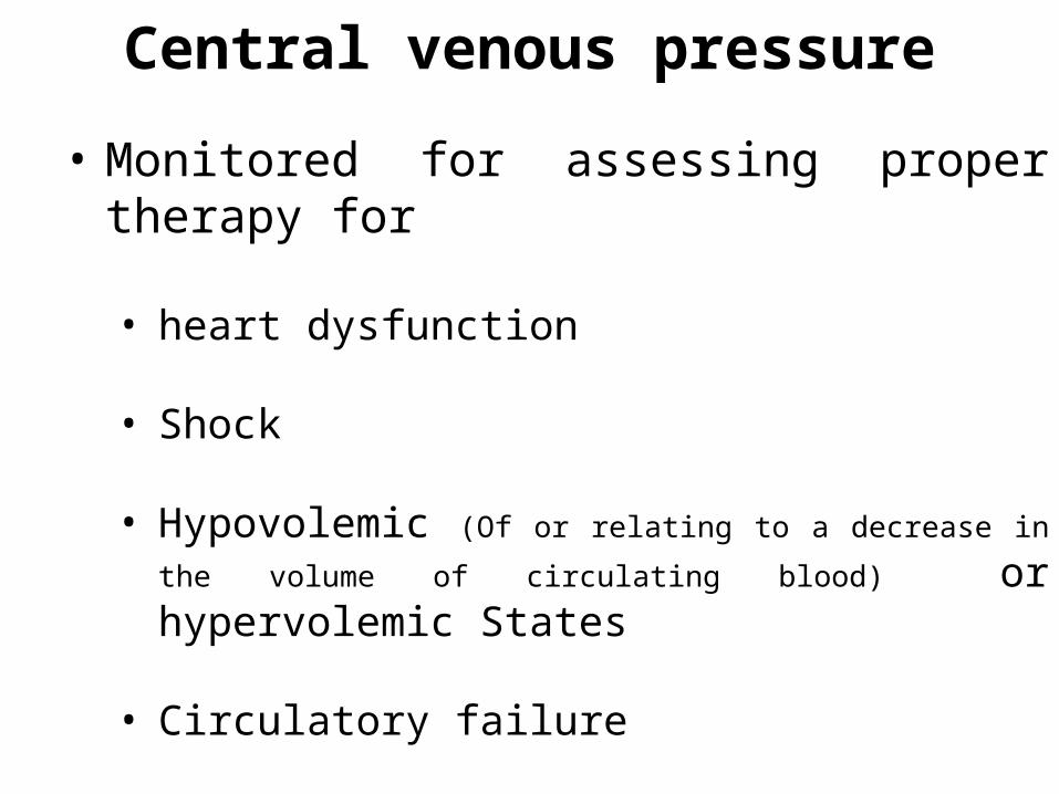
• Monitored for assessing proper therapy for • heart dysfunction
• Shock
• Hypovolemic (Of or relating to a decrease in the volume of
circulating blood) or hypervolemic States
• Circulatory failure
Central venous pressure
• Physicians usually measure steady state or mean venous pressure by making a percutaneous venous puncture with a large bore needle, inserting a catheter through the needle .
• Needle is then removed.
• Continuous dynamic measurements is made by connecting a high sensitive pressure sensor to the venous catheter.
• Normal venous pressure values range widely from 0 to 1.2 kPa with a mean pressure of 0.5 kPa(0 – 12cm H2O).
Central venous pressure
Heart Sounds
• Heart sounds are vibrations or sounds due to the acceleration or deceleration of blood.
• Murmurs are vibrations or sounds due to blood turbulence.
• The technique of listening to sounds produced by the organs and vessels of the body is called auscultation.

Heart Sounds …
Heart Sounds …
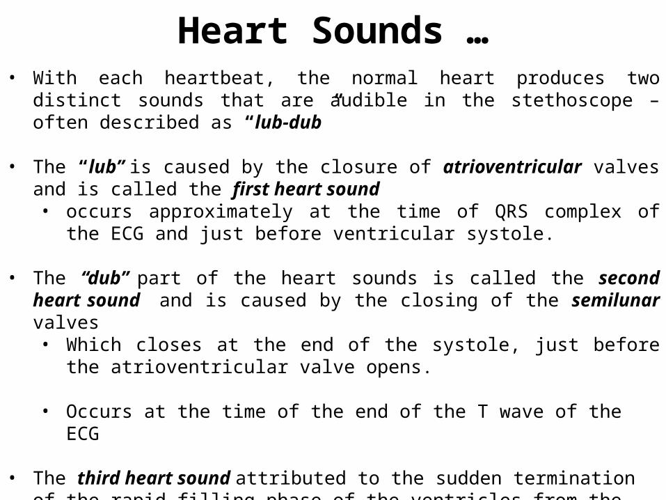
Heart Sounds …• With each heartbeat, the normal heart produces two distinct sounds that are
audible in the stethoscope – often described as “lub-dub”
• The “lub” is caused by the closure of atrioventricular valves and is called the first heart sound • occurs approximately at the time of QRS complex of the ECG and just before
ventricular systole.
• The “dub” part of the heart sounds is called the second heart sound and is caused by the closing of the semilunar valves• Which closes at the end of the systole, just before the atrioventricular valve
opens.
• Occurs at the time of the end of the T wave of the ECG
• The third heart sound attributed to the sudden termination of the rapid filling phase of the ventricles from the atria and the associated vibration of the ventricular muscle walls., which are relaxed.

• Fourth or atrial heart sound – not audible , can be recorded by phonocardiogram, due to atria contract
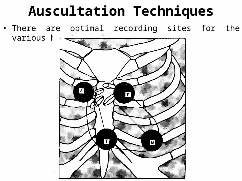
Auscultation Techniques• There are optimal recording sites for the various heart sounds.

Auscultation Techniques…
• Heart sounds and murmurs have extremely small amplitudes with frequencies from 0.1 to 2000 Hz.
• Thus the recording device must be carefully selected for wide band frequency response characteristics.
• Specially designed acoustically quiet environment is needed for noise free recording of heart sounds.
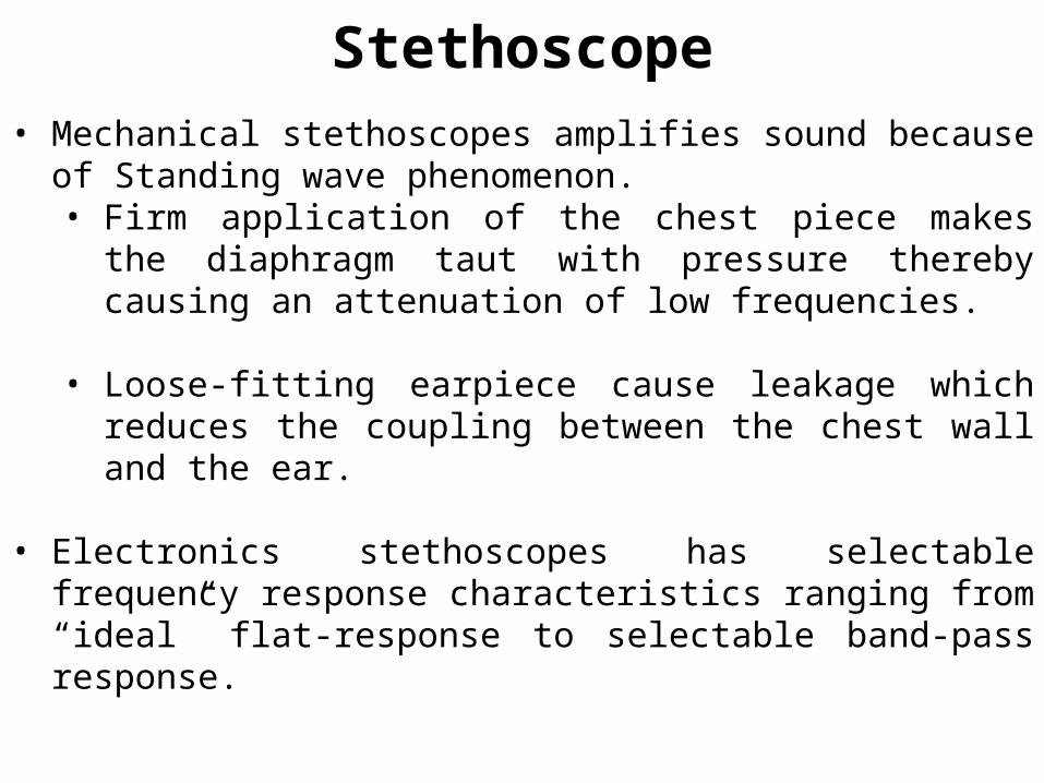
Stethoscope• Mechanical stethoscopes amplifies sound because of Standing wave
phenomenon.• Firm application of the chest piece makes the diaphragm taut
with pressure thereby causing an attenuation of low frequencies.
• Loose-fitting earpiece cause leakage which reduces the coupling between the chest wall and the ear.
• Electronics stethoscopes has selectable frequency response characteristics ranging from “ideal” flat-response to selectable band-pass response.
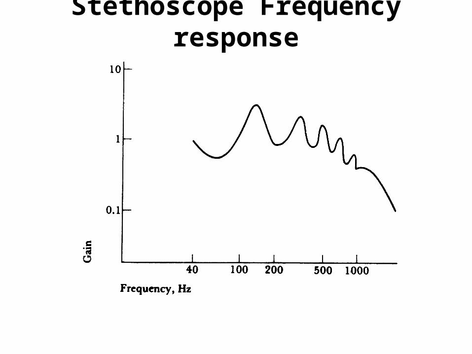
Stethoscope Frequency response

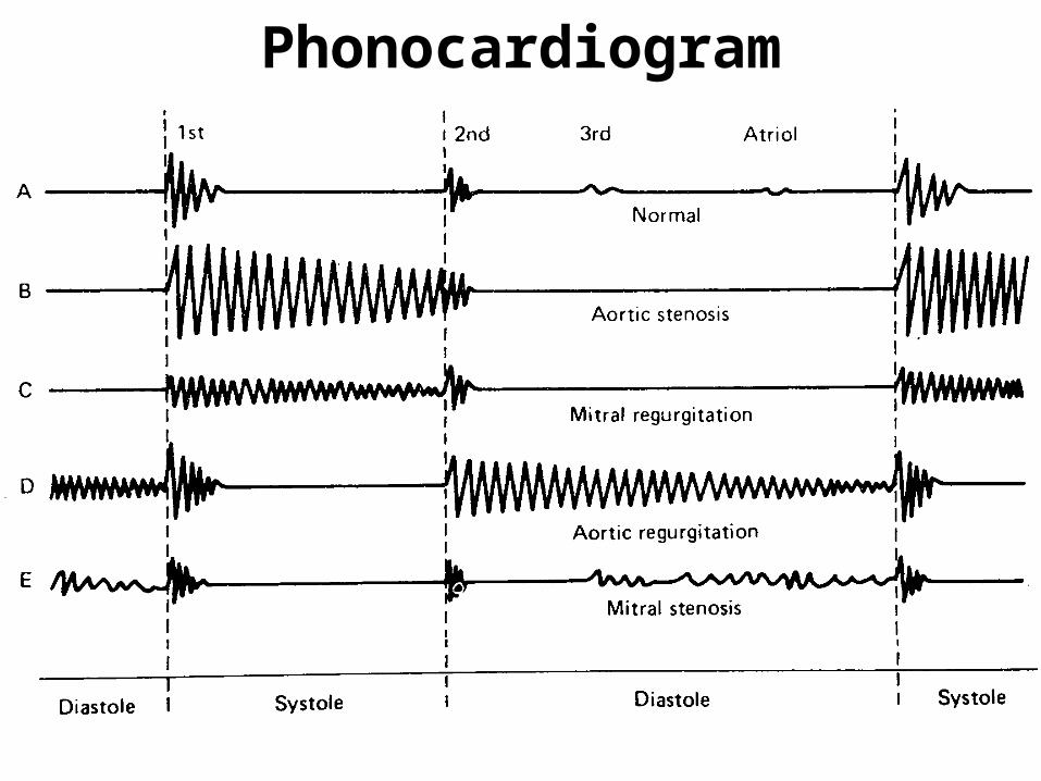
Phonocardiogram
• A Phonocardiogram is a recording of the heart sounds and murmurs.
• Eliminates subjective interpretation of the heart sounds
• Enables evaluation of the heart sounds and murmurs with respect to the electric and mechanical events in the cardiac cycle.
• Evaluation of the result is based on the basis of changes in the wave shape and various timing parameters.
Phonocardiogram
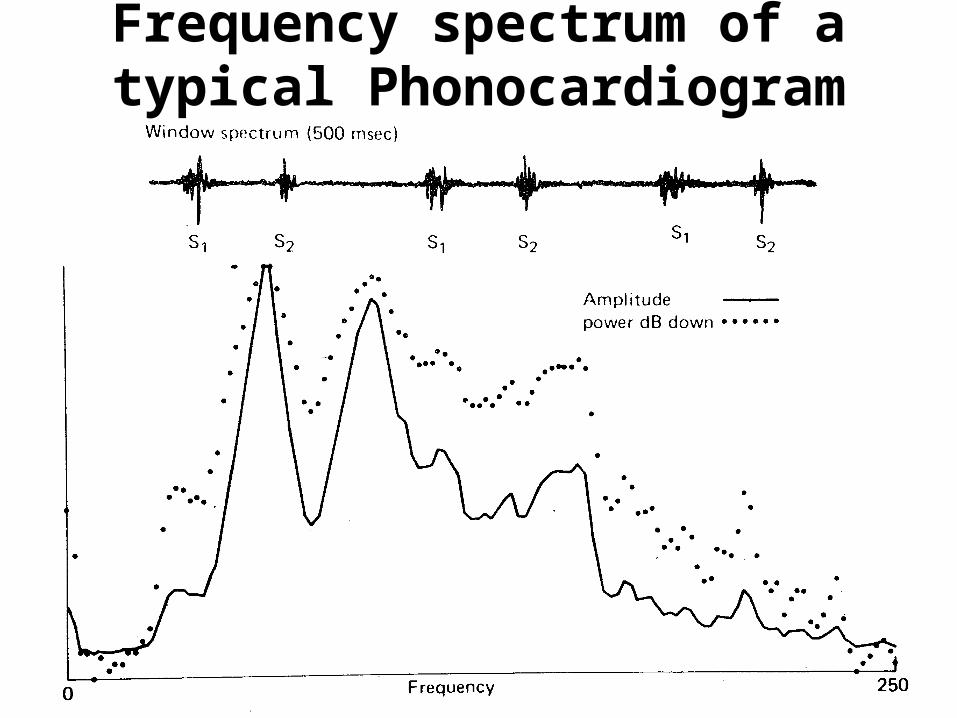
Frequency spectrum of a typical Phonocardiogram
Cardiac Catheterization
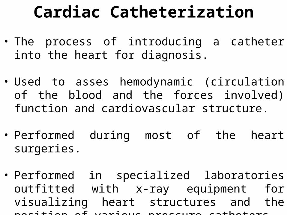
• The process of introducing a catheter into the heart for diagnosis.
• Used to asses hemodynamic (circulation of the blood and the forces involved) function and cardiovascular structure.
• Performed during most of the heart surgeries.
• Performed in specialized laboratories outfitted with x-ray equipment for visualizing heart structures and the position of various pressure catheters.
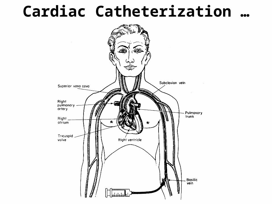
Cardiac Catheterization …
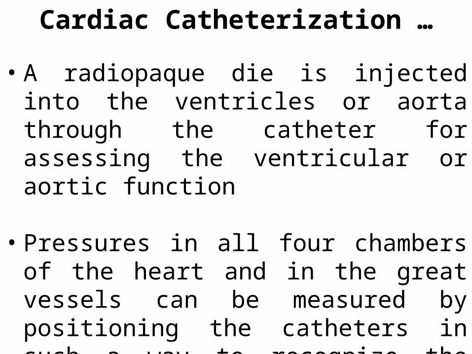
• A radiopaque die is injected into the ventricles or aorta through the catheter for assessing the ventricular or aortic function
• Pressures in all four chambers of the heart and in the great vessels can be measured by positioning the catheters in such a way to recognize the characteristics pressure waveforms.
Cardiac Catheterization …
Angiography
• Angiographic visualization is an essential tool used to evaluate cardiac structure.
• Specially designed catheters and power injectors are used in order that a bolus of contrast material can be delivered rapidly into the appropriate vessel or heart chamber.
• During catheterization cardiac catheterization frequently occur. Clinics must have a functional defbrillaltor
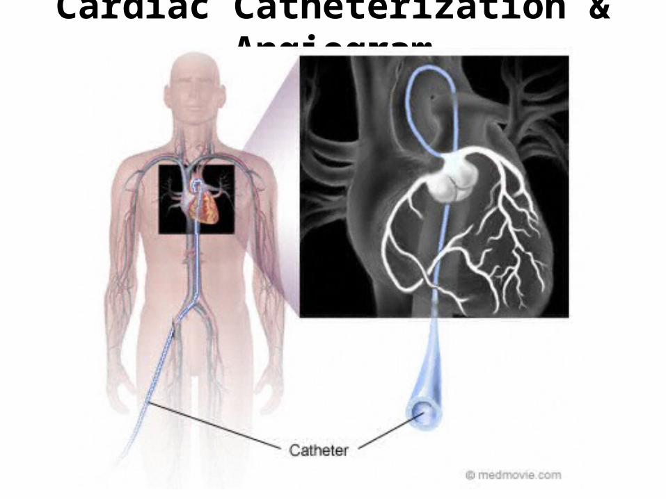
Cardiac Catheterization & Angiogram
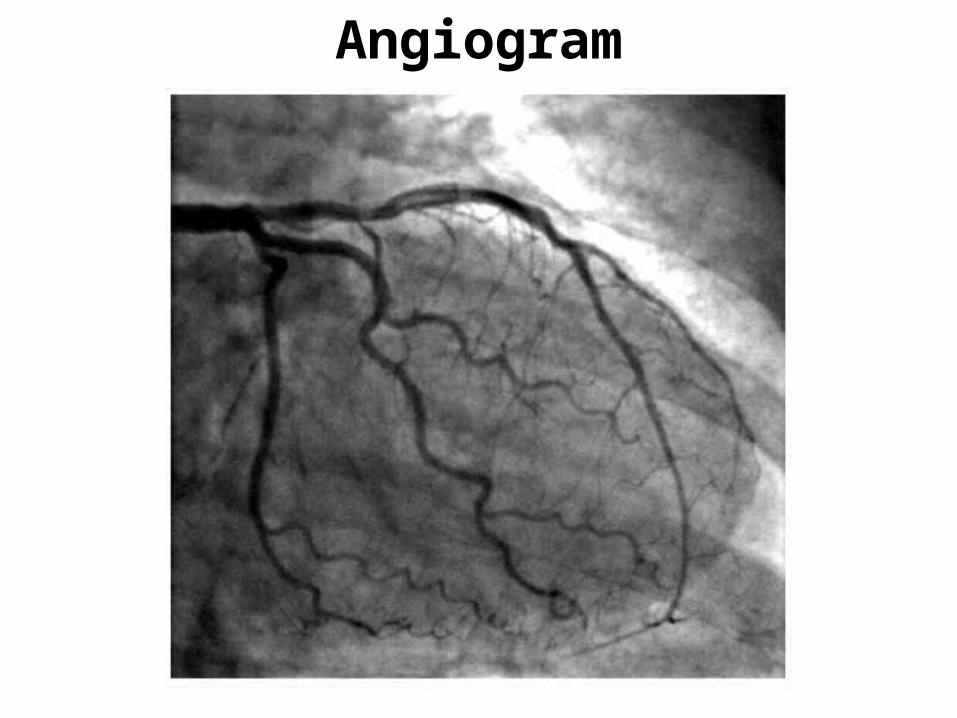
Angiogram

Angeography Types
• Left & Right ventricle – ventriculography• Coronary arteries – coronory angeography• Pulmonary artery – pulmonary angeography• Aorta- aortography

Angioplasty
• Surgical procedure to repair a damaged blood vessel or unblock a coronary artery.• PTCA – Percuntaneous Transluenal
Coronary Angeoplasty
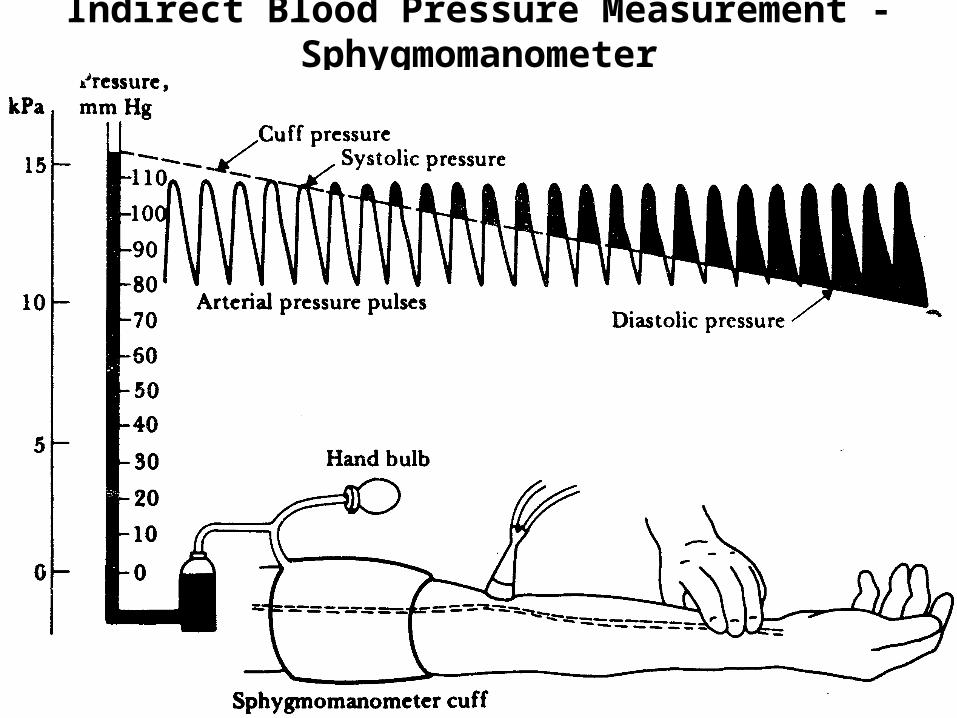
Indirect Blood Pressure Measurement - Sphygmomanometer

Indirect Blood Pressure Measurement - Sphygmomanometer
Indirect Blood Pressure Measurement - Sphygmomanometer
Indirect Blood Pressure Measurement - Sphygmomanometer
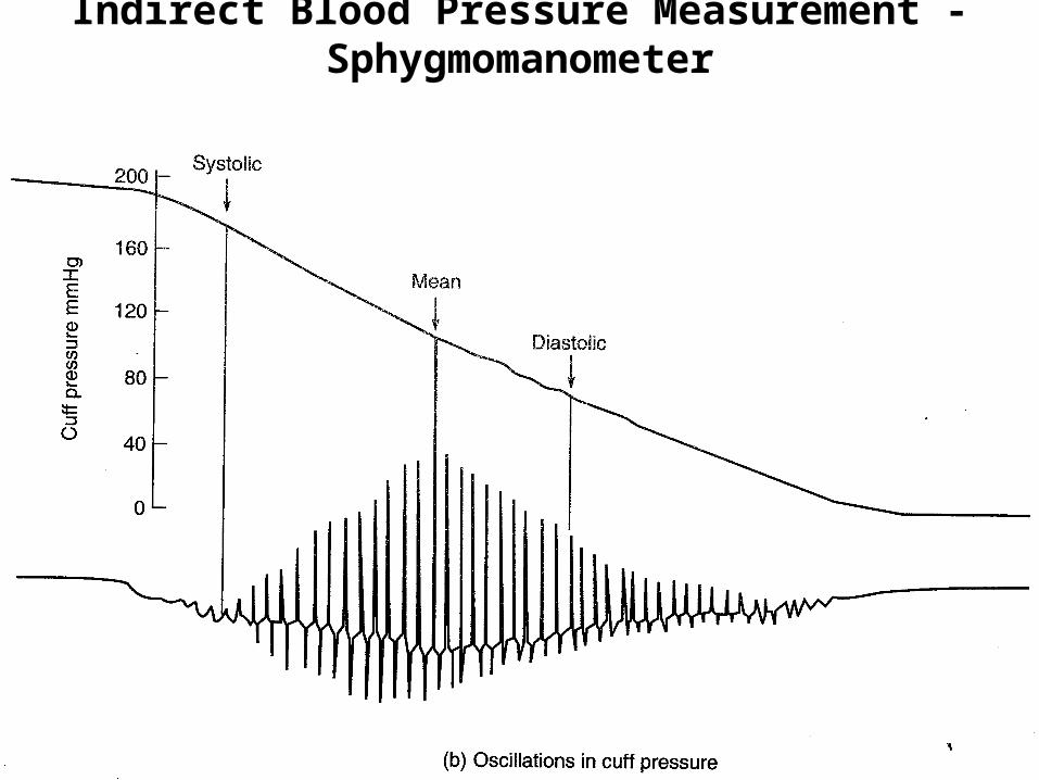
• The pressure cuff on the upper arm is first inflated to a pressure well above the systolic pressure.
• At this point no sound can be heard through the stethoscope, which is placed over the brachial artery, for that artery has been collapsed by the pressure of the cuff.
• The pressure in the cuff is then gradually reduced.
Sphygmomanometery…
• When the systolic peaks are higher than the occlusive pressure, the blood spurts under that cuff and causes a palpable pulse in the wrist (Riva-Rocci Method)
• Audible sounds (Korotkoff (named after Dr. Nikolai Korotkoff) sounds) generated by the flow of blood and vibrations of the vessel under the cuff are heard through the stethoscope.
Sphygmomanometery …
• The pressure of the cuff that is indicated on the manometer when the first Korotkoff sound is heard is recorded as the systolic blood pressure.
• As the pressure in the cuff is continues to drop, the Korotkoff sounds continue until the cuff pressure is no longer sufficient to occlude the vessel during any part of the cycle. Below this pressure the Korotkoff sounds disappear, marking the value of the diastolic pressure.
Sphygmomanometery …
• Auscultatory (based on the Korotkoff sounds) technique is simpler and requires a minimum of equipment.• Cannot be used in noisy environments.
• Palpation (based on pulse on the blood vessel) technique doesn’t require a noise free environment.
• Normal respiration and vasomotor waves modulate the normal blood-pressure levels.
Automated Indirect Blood Pressure measurement techniques
• Involves an automatic sphygmomanometer that inflates and deflates an occlusive cuff at a predetermined rate.
• A sensitive detector is used to measure the distal pulse or cuff pressure.
Automated Auscultatory device
• Microphone replaces the stethoscope for sensing the Korotkoff sounds.
• The process begins with a rapid (20-30mm Hg/s) inflation of the occlusive cuff to a preset pressure about 30mm Hg higher that the suspected systolic pressure.
• The flow of blood beneath the cuff is stopped by the collapse of the vessel.

Automated Auscultatory device
• Cuff pressure is then reduced slowly (2-3 mm Hg/s).
• The first Korotkoff sound is detected by the microphone, at which time the level of the cuff pressure is stored.
Automated Auscultatory device
• The muffling and silent period of the Korotkoff sound is detected, and the value of the diastolic pressure is also stored.
• After a few minutes the instrument displays the systolic and diastolic pressure and recycles the operation
Ultrasonic Based Blood Pressure Measurement
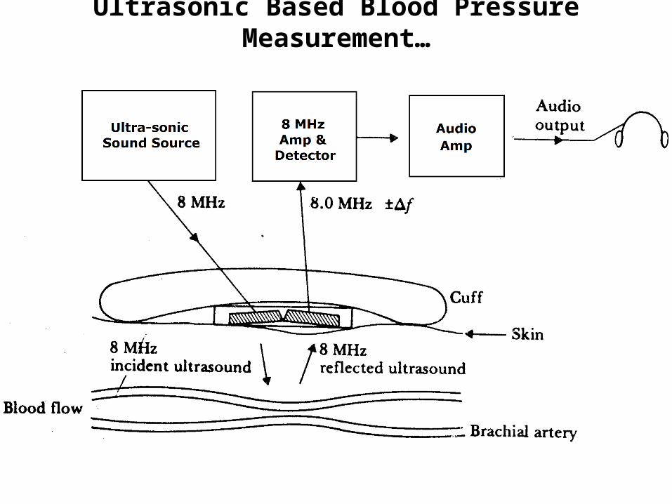
• Employs a transcutaneous Doppler sensor that detects the motion of the blood-vessel walls in the various states of occlusion.
• The Doppler ultrasonic transducer is focused on the vessel wall and the blood.
• The reflected signal (shifted in frequency) is detected by the receiving crystal and decoded.
Ultrasonic Based Blood Pressure Measurement…
Ultrasonic Based Blood Pressure Measurement…
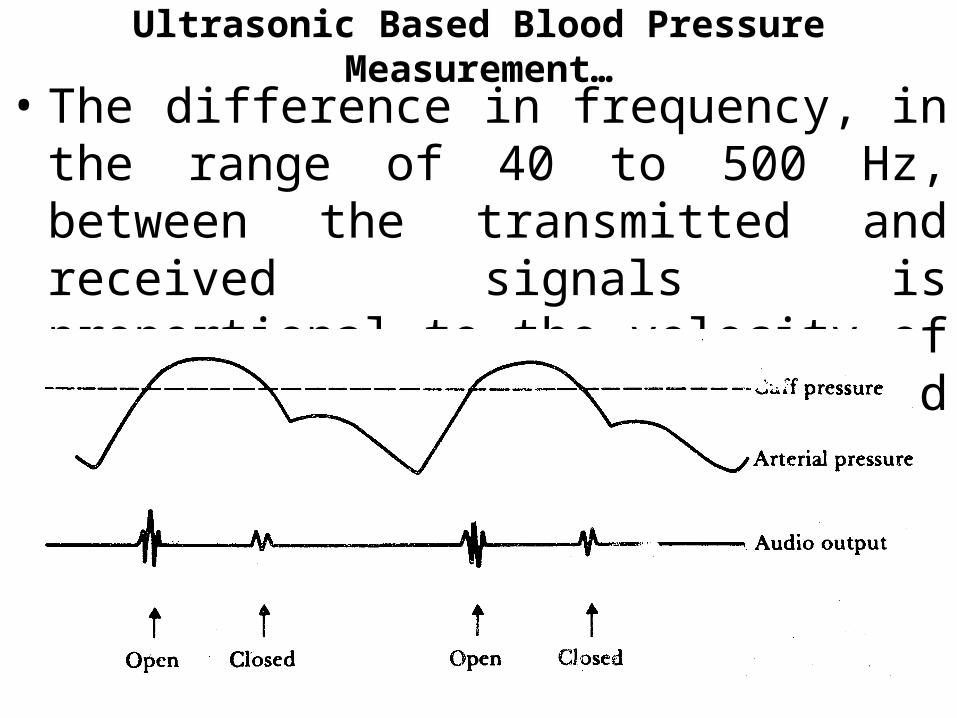
• The difference in frequency, in the range of 40 to 500 Hz, between the transmitted and received signals is proportional to the velocity of the wall motion and the blood velocity.

Ultrasonic Based Blood Pressure Measurement…
• As the applied pressure is further increased, the time between the opening and closing decreases until they coincide. The reading at this point is the systolic pressure.
• When the pressure is cuff is reduced, the time between the opening and closing increases until the closing signal from one pulse coincides with opening signal from the next. The reading at this point is the diastolic pressure.
Ultrasonic Based Blood Pressure Measurement…
• Advantages:• Doesn’t require a noise free environment.
• Disadvantage:• Movement of the subject‘s body cause
changes in ultrasonic path between the sensor and the blood vessel.
Electromagnetic Blood Flow Meters
• Measures instantaneous pulsatile flow of blood
• Works based on the principle of electromagnetic induction
• The voltage induced in a conductor moving in a magnetic field is proportional to the velocity of the conductor
• The conductive blood is the moving conductor
Principle of Electromagnetic Blood Flow Meters

Principle of Electromagnetic Blood flow Measurement
Principle of Electromagnetic Blood Flow Meters
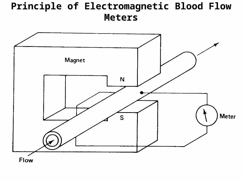
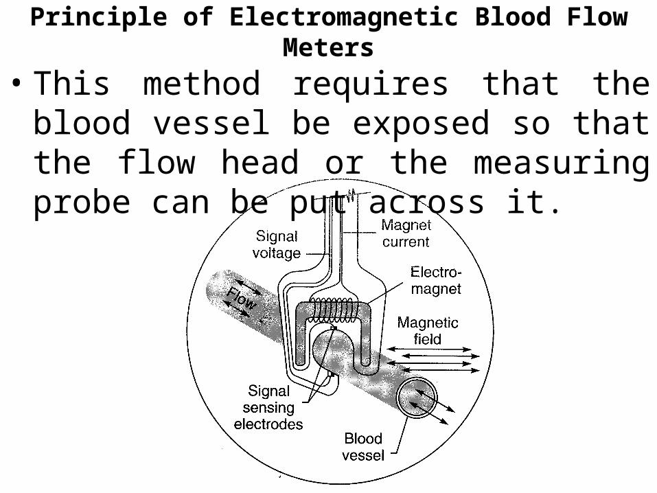
• A permanent magnet or electromagnet positioned around the blood vessel generates a magnetic field perpendicular to the direction of the flow of the blood.
• Voltage induced in the moving blood column is measured with stationary electrodes located on opposite sides of the blood vessel and perpendicular to the direction of the magnetic field.
Principle of Electromagnetic Blood Flow Meters
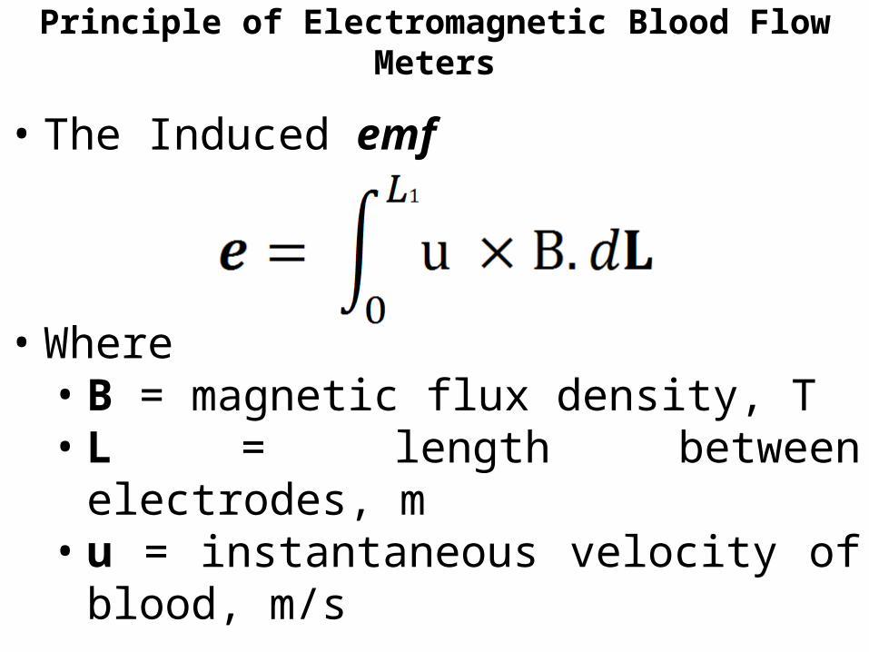
• The Induced emf
• Where• B = magnetic flux density, T• L = length between electrodes, m• u = instantaneous velocity of blood, m/s
Principle of Electromagnetic Blood Flow Meters
• This method requires that the blood vessel be exposed so that the flow head or the measuring probe can be put across it.
Design of Flow Transducers• The electromagnetic flow-transducer is a tube of
non-magnetic material to ensure that the magnetic flux does not bypass the flowing liquid and go into the walls of the tube.
• The tube is made of a conducting material and generally has an insulating lining to prevent short circuiting of induced emf.
• The induced emf is picked up by point electrodes made from stainless steel or platinum.

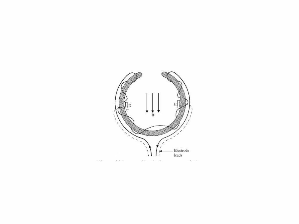
Design of Flow Transducers• The flow head contains a slot through which the
intact blood vessel can be inserted to make a snug fit.
• Several probes of different sizes must therefore accompany the flowmeter to match the full range of sizes of the blood vessels which have various diameters.
• Flow heads having as small as 1mm are available.
Types of Electromagnetic Blood Flow Meters
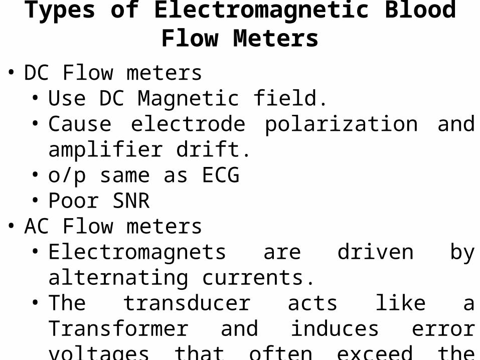
• DC Flow meters• Use DC Magnetic field.• Cause electrode polarization and amplifier drift.• o/p same as ECG• Poor SNR
• AC Flow meters• Electromagnets are driven by alternating
currents.• The transducer acts like a Transformer and
induces error voltages that often exceed the signal levels by several orders of magnitude.
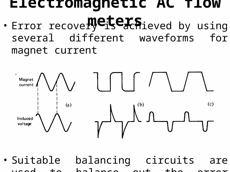
Electromagnetic AC flow meters• Error recovery is achieved by using several different
waveforms for magnet current
• Sine, Square, Trapezoidal.
• Suitable balancing circuits are used to balance out the error voltage.

Sine wave Flowmeters• The transformer induced voltage is 90˚ out of
phase and is eliminated by
• Injecting a voltage of equal strength and opposite phase into the signal.
• Using a gated amplifier.• Permit the amplification of the signal
only during the flow induced voltages are maximum and the transformer induced voltages are minimum.
Square wave Flowmeters• The transformer induced voltage is only a
spike.
• Separation is easier as the amplifier can be gated only for a very short period.
• Blanking is required only when the current in the magnet is reversing its direction and the amplifier works during the flat portion of the square wave.
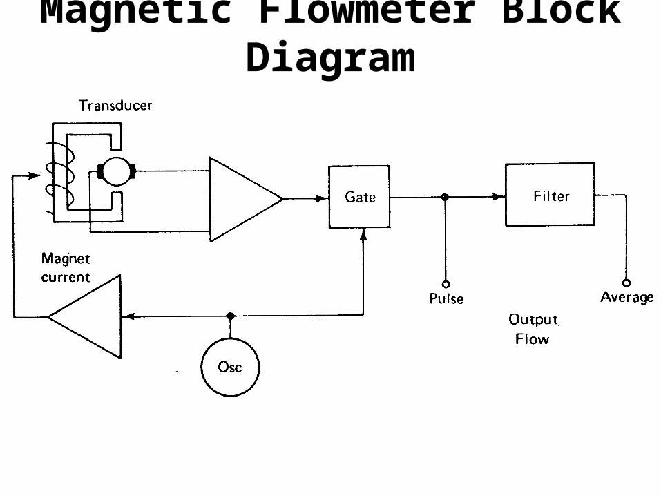
Magnetic Flowmeter Block Diagram
Magnetic Flowmeter Block Diagram• The oscillator, which drives the magnet
provides a control signal for the gate, operates at a frequency of between 60 and 400 Hz.
• The frequency response is high enough to allow the recording of the flow pulses.
• The mean or average flow can be derived by use of a low-pass filter.

Ultrasonic Blood Flow Meters
• A beam of ultrasonic energy is used to measure the velocity of flowing blood.
. Lead zirconate titanate is a crystal that has thehighest conversion efficiency.
• Two types:
• Transit time flow meters• Doppler type.
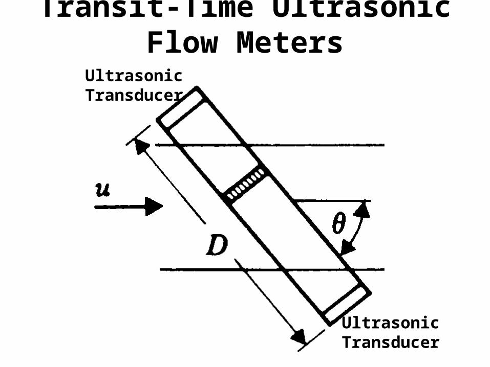
Transit-Time Ultrasonic Flow Meters
Ultrasonic Transducer
Ultrasonic Transducer
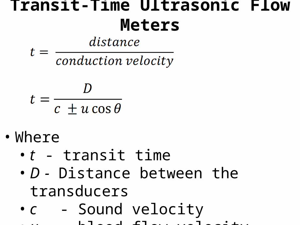
Transit-Time Ultrasonic Flow Meters
• Where• t - transit time• D - Distance between the transducers• c - Sound velocity• u - blood flow velocity
Transit-Time Ultrasonic Flow Meters
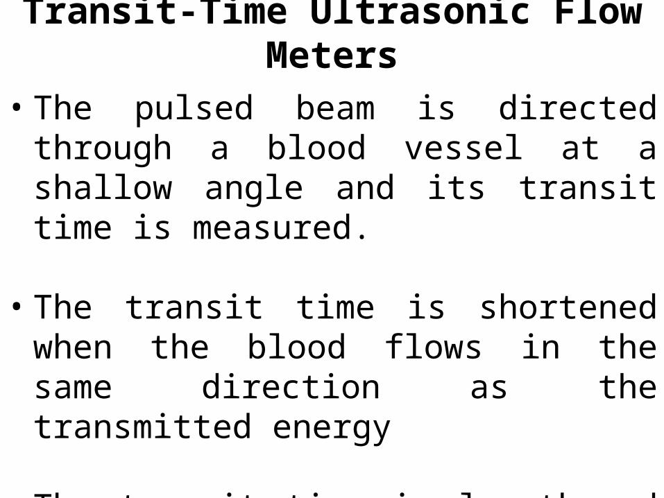
• The pulsed beam is directed through a blood vessel at a shallow angle and its transit time is measured.
• The transit time is shortened when the blood flows in the same direction as the transmitted energy
• The transit time is lengthened otherwise.
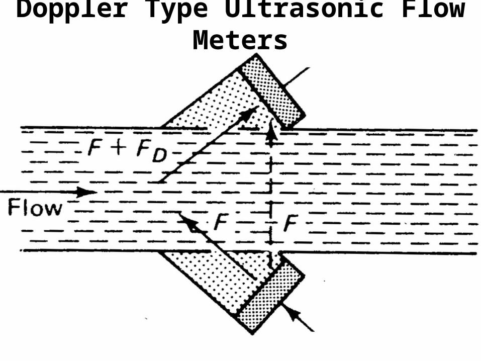
Doppler Type Ultrasonic Flow Meters
Doppler type Ultrasonic Flow Meters
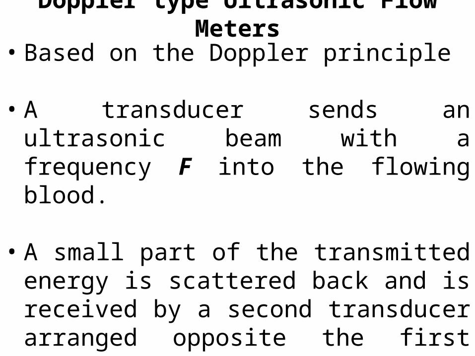
• Based on the Doppler principle
• A transducer sends an ultrasonic beam with a frequency F into the flowing blood.
• A small part of the transmitted energy is scattered back and is received by a second transducer arranged opposite the first one.
• The reflected signal has a different frequency F + FD or F – FD due to Doppler effect.
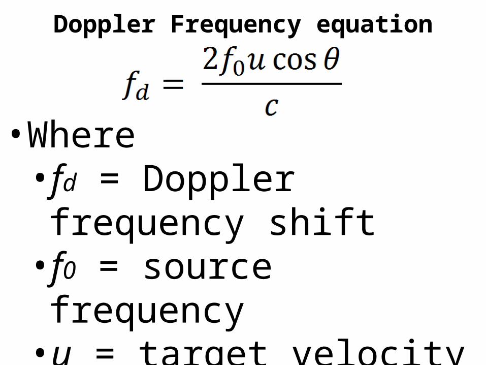
Doppler Frequency equation
•Where• fd = Doppler frequency shift• f0 = source frequency• u = target velocity• c = velocity of sound
Doppler type Ultrasonic Flow Meters…
• The Doppler component FD is directly proportional to the velocity of the flowing blood.
• A fraction of the transmitted ultrasonic energy reaches the second transducer directly with the frequency being unchanged.
Doppler Type Ultrasonic Flow Meters

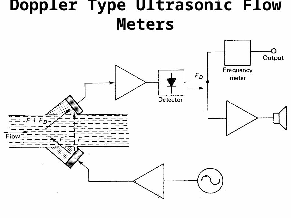
Doppler type Ultrasonic Flow Meters…
• After amplification of the composite signal, the Doppler frequency can be obtained at the output of the detector as the difference between the direct and the scattered signal components.
• For normal blood velocities, the Doppler signal is typically in the low audio frequency range.
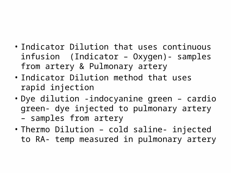
• Indicator Dilution that uses continuous infusion (Indicator – Oxygen)- samples from artery & Pulmonary artery
• Indicator Dilution method that uses rapid injection• Dye dilution -indocyanine green – cardio green-
dye injected to pulmonary artery – samples from artery
• Thermo Dilution – cold saline- injected to RA- temp measured in pulmonary artery
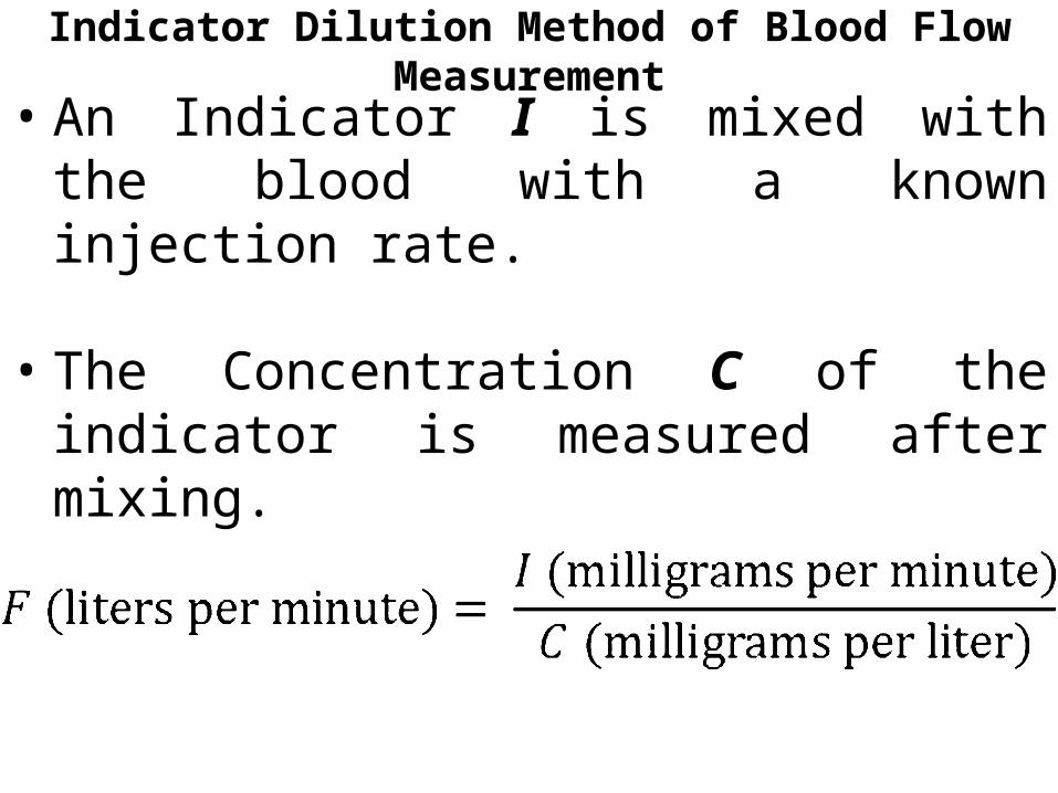
Indicator Dilution Method of Blood Flow Measurement
• An Indicator I is mixed with the blood with a known injection rate.
• The Concentration C of the indicator is measured after mixing.
• Then the flow,
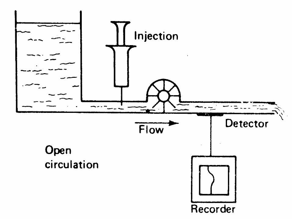
Indicator Dilution Method of Blood Flow Measurement
Indicator Dilution Method of Blood Flow Measurement
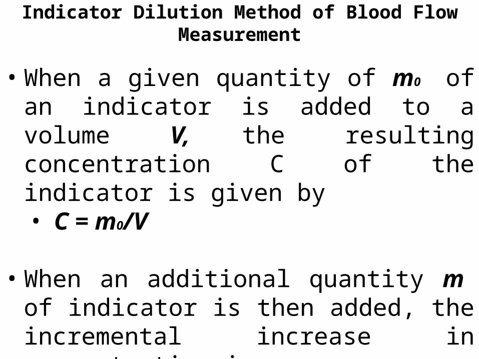
• When a given quantity of m0 of an indicator is added to a volume V, the resulting concentration C of the indicator is given by• C = m0/V
• When an additional quantity m of indicator is then added, the incremental increase in concentration is • ΔC = m/V
Indicator Dilution Method of Blood Flow Measurement
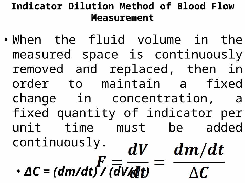
• When the fluid volume in the measured space is continuously removed and replaced, then in order to maintain a fixed change in concentration, a fixed quantity of indicator per unit time must be added continuously.
• ΔC = (dm/dt) / (dV/dt)
• Then the Flow,
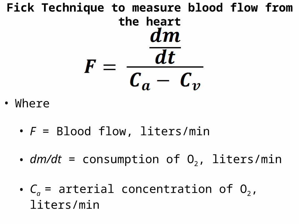
Fick Technique to measure blood flow from the heart
• Where
• F = Blood flow, liters/min
• dm/dt = consumption of O2, liters/min • Ca = arterial concentration of O2, liters/min
• Cv = venous concentration of O2, liters/min
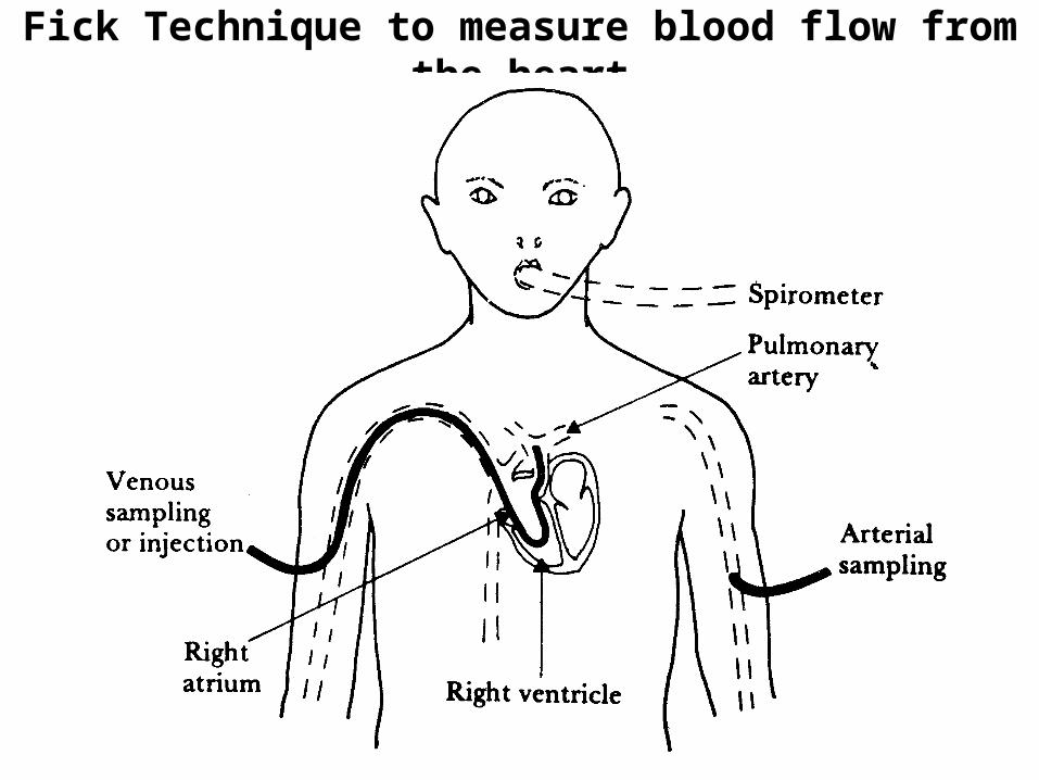
Fick Technique to measure blood flow from the heart

Fick Technique to measure blood flow from the heart
• The blood returning to the heart from the upper half of the body has a different concentration of O2 from the blood returning fromthe lower half.
• The O2 concentration measured by the spirometer
• The arterial-venous concentration difference is measured by drawing samples through catheters placed in an artery and in the pulmonary artery.

• Cv can be measure it in the pulmonary artery after it has been mixed by the pumping action of the right ventricle.
• The clinician can measure the concentration of the oxygenated blood Ca in any artery.
Fick’s Technique - Advantage
• The Fick technique is nontoxic, because the indicator (O2) is a normal metabolite that is partially removed as blood passes through the systemic capillaries.
• The cardiac output must be constant over several minutes so that the investigator can obtain the slope of the curve for O2 consumption.
• The presence of the catheter causes a negligible change in cardiac output.
Indicator Dilution Method that uses rapid injection
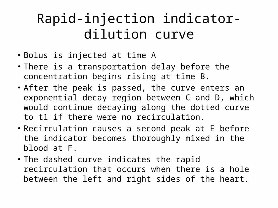
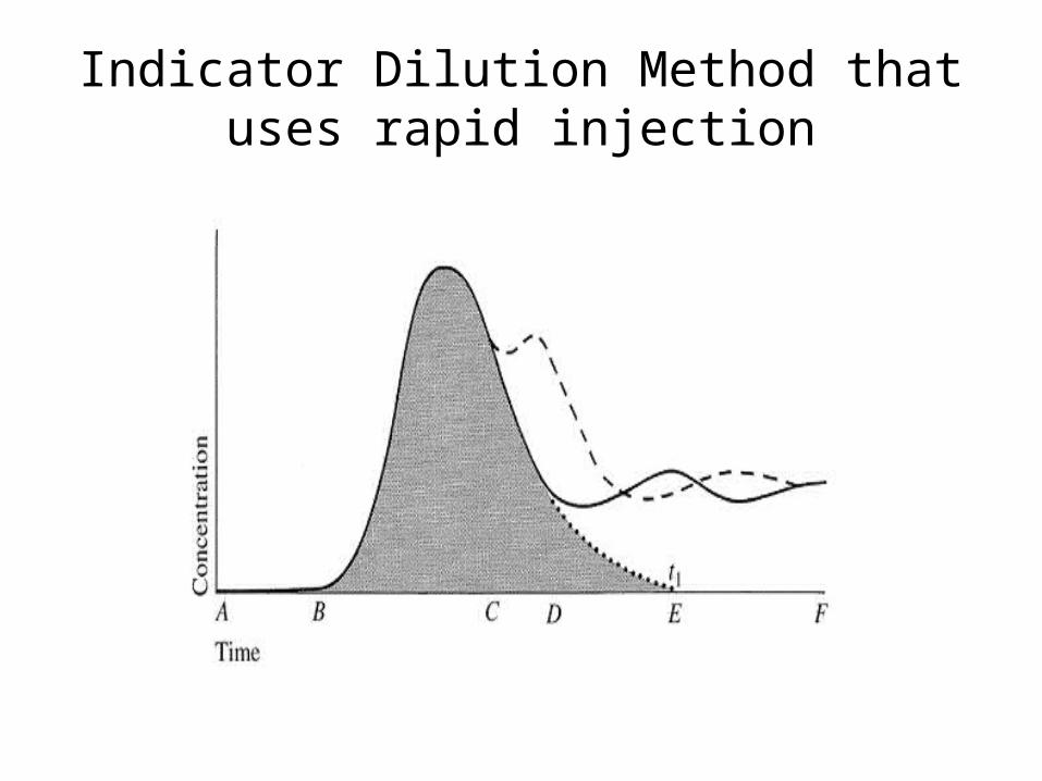
Rapid-injection indicator-dilution curve
• Bolus is injected at time A• There is a transportation delay before the concentration begins
rising at time B. • After the peak is passed, the curve enters an exponential decay
region between C and D, which would continue decaying along the dotted curve to t1 if there were no recirculation.
• Recirculation causes a second peak at E before the indicator becomes thoroughly mixed in the blood at F.
• The dashed curve indicates the rapid recirculation that occurs when there is a hole between the left and right sides of the heart.

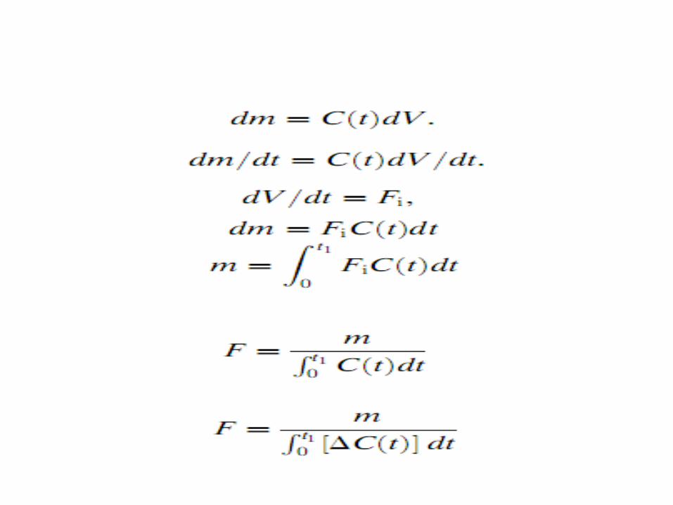
• An increment of blood of volume dV passes the sampling site in time dt.
• quantity of indicator dm contained in dV is the concentration C(t) times incremental volume.
• Hence dm =C(t) dV . Dividing by dt, we obtain (dm/dt)= C(t) (dV/dt)
• dm= Fi C(t) dt

• where t1 is the time at which all effects of the first pass of the bolus have died out (point E).
• The integrated quantity (∫ C(t) dt) ) is equal to the shaded area in Figure we can obtain it by counting squares or using a planimeter.
• If the initial concentration of indicator is not zero—as may be the case when there is residual indicator left over from previous injections( C(t) - > ∆ C(t) )
Properties of Indicator
• (1) inert, • (2) harmless, • (3) measurable, • (4) economical,• (5) always intravascular.
DYE DILUTION
• A common method of clinically measuring cardiac output is to use a
• colored dye, indocyanine green (cardiogreen).• It meets the necessary requirements for an indicator • The dye is available as a liquid that is diluted in isotonic
saline and injected directly through a catheter, usually into the pulmonary artery.
• About 50% of the dye is excreted by the kidneys in the first 10 min, so repeat determinations are possible.

• The plot of the curve for concentration versus time is obtained from a constant-flow pump, which draws blood from a catheter placed in the femoral or brachial artery.
• Blood is drawn through a colorimeter cuvette which continuously measures the concentration of dye, using the principle of absorption photometry.
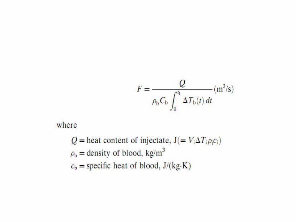
Thermo Dilution
• Injecting a bolus of cold saline as an indicator. • A special four-lumen catheter is floated through
the brachial vein into place in the pulmonary artery.
• 1- A syringe forces a gas through one lumen; • 2-The cooled saline indicator is injected through
the second lumen into the right atrium. • 3- The third lumen carries the thermistor wires. • 4- Used for withdrawing blood samples.

• The gas inflates a small, doughnut-shaped balloon at the tip.
• The indicator is mixed with blood in the right ventricle.
• The resulting drop in temperature of the blood is detected by a thermistor located near the catheter tip in the pulmonary artery
Related Documents