Blok, L., Woods, B. K. S., Yu, H., Longana, M., & Potter, K. (2017). 3D PRINTED COMPOSITES – BENCHMARKING THE STATE-OF-THE- ART. 1-9. Paper presented at 21st International Conference on Composite Materials, Xi'an, China. Peer reviewed version Link to publication record in Explore Bristol Research PDF-document This is the author accepted manuscript (AAM). The final published version (version of record) is available online via ICCM at http://www.iccm21.org/index.php?m=content&c=index&a=lists&catid=5. Please refer to any applicable terms of use of the publisher. University of Bristol - Explore Bristol Research General rights This document is made available in accordance with publisher policies. Please cite only the published version using the reference above. Full terms of use are available: http://www.bristol.ac.uk/pure/about/ebr-terms

Welcome message from author
This document is posted to help you gain knowledge. Please leave a comment to let me know what you think about it! Share it to your friends and learn new things together.
Transcript

Blok, L., Woods, B. K. S., Yu, H., Longana, M., & Potter, K. (2017). 3DPRINTED COMPOSITES – BENCHMARKING THE STATE-OF-THE-ART. 1-9. Paper presented at 21st International Conference on CompositeMaterials, Xi'an, China.
Peer reviewed version
Link to publication record in Explore Bristol ResearchPDF-document
This is the author accepted manuscript (AAM). The final published version (version of record) is available onlinevia ICCM at http://www.iccm21.org/index.php?m=content&c=index&a=lists&catid=5. Please refer to anyapplicable terms of use of the publisher.
University of Bristol - Explore Bristol ResearchGeneral rights
This document is made available in accordance with publisher policies. Please cite only the publishedversion using the reference above. Full terms of use are available:http://www.bristol.ac.uk/pure/about/ebr-terms

21st International Conference on Composite Materials
Xi’an, 20-25th August 2017
1
3D PRINTED COMPOSITES – BENCHMARKING THE
STATE-OF-THE-ART
L.G. Blok1, B.K.S. Woods, H. Yu, M.L. Longana, K.P. Potter
1 Bristol Composites Institute (ACCIS), University of Bristol, Queen’s
Building, University Walk, Bristol, BS8 1TR, UK
Keywords: composite, thermoplastic, 3D printing, additive manufacture, short
fibres, alignment
ABSTRACT
Fused filament fabrication (FFF) is a 3D printing technique which allows layer-by-
layer build-up of a part by the deposition of thermoplastic material through a nozzle. The
technique allows for complex shapes to be made with a degree of design freedom
unachievable with traditional manufacturing methods. However, the mechanical
properties of the thermoplastic materials used are low compared to common engineering
materials. In this work, improved 3D printing feedstocks for FFF, with carbon fibres
embedded in a thermoplastic matrix to reinforce the material, are investigated. The state-
of-the-art in composite 3D printing is reviewed and the capabilities of two different
commercially available composite printing methods are assessed by print trials, optical
microscopy and mechanical characterization of the printed materials. It is found that
printing of continuous carbon fibres using the MarkOne gives significant increases in
performance over unreinforced thermoplastics, with mechanical properties in the same
order of magnitude of typical unidirectional epoxy matrix composites. The method,
however, is limited in design freedom as the brittle continuous carbon fibres cannot be
deposited freely through small steering radii and sharp angles. Filaments with embedded
carbon microfibres (~100 μm) show better print capabilities and are suitable with
standard printing methods, but only offer a slight increase in mechanical properties over
the pure thermoplastic properties.
1 INTRODUCTION
Carbon fibres reinforced plastics (CFRPs) provide excellent mechanical properties and allow for
significant design tailorability. A fundamental CFRPs manufacturing challenge, however, is the
combination of the reinforcement fibres into the polymer matrix with good consolidation, maximum fibre
orientation control and low cost [1]. While a wide range of manufacturing methods for composites are
available, most FRP parts are formed in a two-step process, i.e. material lay-up followed by
consolidation. For good consolidation, pressure needs to be applied over the entire part surface area
which requires expensive equipment and increases manufacturing costs. In this work, additive
manufacture (AM) techniques and more specifically fused filament fabrication (FFF), is investigated as
an alternative CFRP manufacturing approach where low investment costs and rapid prototyping ability
are important.
Layer-by-layer (LbL) manufacturing techniques, such as FFF, commonly known as 3D printing, have
an underappreciated similarity to traditional composite materials in that they are made from stacking a
series of discrete layers. It is therefore reasonable to suggest that successful adaptation of 3D printing
technologies to composite materials could enable a simple method for composite manufacture with lower
production cost and a high degree of automation. While still a relatively undeveloped avenue of research,
there is at least one company developing commercial 3D printers capable of printing continuous fibre
reinforced composite materials: MarkForged [2]. The Mark One and Mark Two printers developed by
MarkForged print continuous carbon fibre reinforced nylon with high mechanical properties, comparable
to aluminium, to open up new applications in both the personal fabrication market and in the manufacture
of lightweight parts for industry. As reinforcements can be accurately placed, the laminated structure of
21st International Conference on Composite Materials
Xi’an, 20-25th August 2017
2
composite parts can be further optimised in each layer, allowing for an increase in design freedom and
mechanical performance.
However, significant challenges remain for 3D printing of CFRPs. In addition to some process
specific limitations with the MarkForged printers, which will be discussed in further detail below, there
are more fundamental issues which need addressing. For example, there is limited choice of materials
suitable for 3D printing and to obtain a high strength composite part the void content needs to be
minimal. During printing, however, a filament bead is deposited beside or on top of another filament and
the interface quality is determined by the polymer sintering process that happens without the application
of external pressure or extra heat. Fibres may be first embedded in a thermoplastic matrix in a pre-
processing stage but the final part strength greatly depends on the final interface between the different
printed beads.
A brief overview of the state-of-art in composite 3D printing is given here and two different methods
of composite 3D printing, i.e. continuous fibre printing and discontinuous fibre printing, are
experimentally characterised. Comparisons were made between the two printing methods in terms of
mechanical properties and print quality. The highest mechanical properties were obtained with the
continuous fibre printing method but the printing process was less versatile and had a lower quality than
discontinuous fibre printing as continuous fibres could not completely fill small features and tight radii.
2 STATE-OF-THE-ART
The FFF process can be utilized to print CFRPs by the addition of fibres into the thermoplastic
filament. Besides the obvious motivation of increasing mechanical properties, the reinforcement may also
be used to add extra functionality to the material such as electroconductivity, higher heat conductivity or
improved mechanical properties. Kalsoom et al. [3] and Wang et al. [4] recently provided a general
overview of 3D printable composite materials, here a specific focus on the FFF process is given. The use
of fibre reinforcements in 3D printing filaments for FFF is a topic of on-going research with both
advancements in scientific literature as well as in commercial products, e.g. the MarkForged printers and
the numerous reinforced thermoplastic filaments available on the market [2], [5]–[12].
Most studies report on the use of very short carbon fibres (100 μm) which are mixed with a
thermoplastic resin and then extruded to create the filament used for traditional printing. This increases
the strength and stiffness of the printed material by around 65%, but remains low compared to typical
unidirectional continuous CFRPs.
Ning et al. [5] produced reinforced filament using screw extrusion with varying fibre content from 0
to 7.5 wt% and a fibre length of 100 μm. They found an increase in tensile and flexural properties (tensile
strength from 34 to 42 MPa and tensile stiffness from 2 GPa to 2.5 GPa). One limitation they noted was
that during the screw extrusion process, the brittle fibres break which limits their length in the filament
and consequently they do not reach their full strength. Tekinalp et al. [6] used a similar process to add up
to 40wt% of carbon fibres with an average length of 0.26mm to ABS and investigated the print quality
and mechanical properties. The strength increased from 35 to 65MPa and the stiffness from 2GPa to 14
GPa. They characterized the voids and found that the size of inter-bead voids decreased with the addition
of fibres but secondary voids occurred around the fibre/matrix interface.
Recently, Lewicki et al. [12] reported on the direct ink writing method of carbon fibre reinforced
epoxy, which used syringe extrusion with a fast curing epoxy to build up the composite part layer-by-
layer. They used 600 μm fibres and found that silicate nanoparticles had to be added to increase the
viscosity of the resin to prevent the resin flowing past the fibres. The strength increased with the addition
of fibres from 85 MPa to 172 MPa and the stiffness increased from 2 GPa to 5.5 GPa. Numerical analysis
was done to analyse the fibre alignment in the nozzle – an approach which may provide an effective tool
in future work to minimise clogging within the fibre nozzle.
MarkForged has developed a printer which deposits continuous fibres (carbon, glass and Kevlar) in a
Nylon matrix. A ~0.4mm diameter continuous fibre/Nylon filament is fed through a nozzle and, after
initial contact with and adhesion to the printing bed (thereby anchoring the filament), can be dragged
along a custom path. To finish printing the continuous fibre, the reinforced filament is cut with a shear
cutter. The reported strength and stiffness of printed parts with carbon fibres are 700 MPa and 50 GPa
respectively [2]. Printing with continuous carbon fibres is also done by Anisoprint which report a
strength and modulus of 760 MPa and 42 GPa respectively. The matrix type and printing method is

21st International Conference on Composite Materials
Xi’an, 20-25th August 2017
3
unknown as it is not commercialized at the time of writing, but the fibre volume fraction, Vf, was
reported to be 18.5% [11]. Matsuzaki et al. [7] printed continuous fibres (straight carbon fibres or
twisted jute fibre yarns) by feeding them through a nozzle simultaneously with a thermoplastic filament
(PLA) which acts as a matrix. They reported a strength and stiffness of 195 MPa and 10.5 GPa
respectively which may be attributed to a low Vf of 6.6%. This technique also showed a non-uniform
fibre distribution as the fibres were not pre-impregnated in the matrix.
The printing of continuous fibres adds complexity to the printing process. Cutting of the filament is
required for placement of fibres along different tracks and in different layers. The shape is also limited by
the steering radius of the fibre, as continuous fibres cannot deform plastically along their length, while
fibre straightness and alignment must be maintained for optimal structural performance [13]. The
addition of continuous fibres to thermoplastic filament, however, shows a larger improvement in
mechanical properties compared to the microfiber (~100 μm) reinforced filaments. Discontinuous fibres
in a polymer matrix may not reach their full strength as the matrix or fibre-matrix interface fails before
the fibres unless their length is above a “critical length” [14-16] [14],[15], [16].
Concluding, two main printing methods can be identified, the printing of discontinuous fibres with
traditional printing methods and continuous fibre printing with a custom printing head and technique. To
contribute to the body of knowledge on composite printing, the two printing methods are further
investigated here in terms of mechanical properties and printing characteristics before drawing
conclusions on the different composite printing techniques.
3 EXPERIMENTAL METHODOLOGY
Two composite 3D printing methods are assessed. The Mark Forged MarkOne printer is used to print
continuous carbon fibre / Nylon composite parts, characterise the mechanical properties and investigate
the printing characteristics as a composite printing benchmark. Secondly, carbon microfibre reinforced
PLA filament is used in a traditional FFF printer to compare against the MarkOne in terms of mechanical
properties and quality. The methodology for these two investigations is presented below.
3.1 MarkOne continuous fibre printer characterization
The MarkOne printer is a proprietary 3D printer which can deposit a filament made of continuous
fibre embedded in a Nylon matrix. The printer has two printing nozzles as shown in Figure 1, one to
deposit pure Nylon filament, and one for fibre reinforced Nylon filament. Three fibre reinforced
filaments are available with Kevlar, glass or carbon fibres and the two-nozzle system enables printing of
Nylon as well as fibre reinforced layers. This unreinforced Nylon nozzle is crucial for the overall
integrity and quality of the prints, as the fibre filament can not be used for the outer layers of the parts
(top, bottom, sides), and for more complex shapes and thin features there are often large regions in which
the fibre filament is not able to fill which instead are filled with the unreinforced Nylon. The Nylon
filament and Nylon/fibre filament are pushed through a Teflon bowden tube to the nozzles, as highlighted
in Figure 1.
Figure 1: Overview of the MarkOne Printer with the dual nozzle system to print Nylon filament and fibre
filament.
To print an object, a proprietary software, which does not allow manual control of temperature, nozzle
movement or extrusion speed, must be used. This limits the printing capabilities as the printing settings
21st International Conference on Composite Materials
Xi’an, 20-25th August 2017
4
cannot be fully customized. When printing the Nylon material, it is possible to specify the fill percentage
and fill type (rectangular, triangular or hexagonal). For the deposition of carbon fibres, only a
circumferential fill pattern is possible which fills the shape from the outside inward in a spiraling motion.
This means the fibre is always orientated along the outer shape of the part.
To print, a 3D object is sliced into layers with a layer height of 0.125 mm for carbon fibre reinforced
layers. The bottom and top layers are always printed with the 100% triangular fill Nylon filament, as well
as the outer periphery for each layer. This is presumably done to avoid exposed fibres on the outer
surface and to take advantage of the higher quality surface finish and accuracy available from the
unreinforced Nylon. While this feature exists for sensible reasons, it has the negative effect of lowering
the overall fibre volume fraction for the part - and thus the maximum achievable mechanical properties.
Printing was done at 260 °C with an estimated speed of 6.90 cm3/hr for the Nylon layers and 2.39 cm3/hr
for the carbon fibre layers.
To provide a reliable and generally useful benchmark of the MarkOne printer, the most extensive suite
of mechanical tests and printing trials reported to date were performed. The tensile, shear and flexural
response of the printed material have been measured. To get around the limitations in fibre orientation
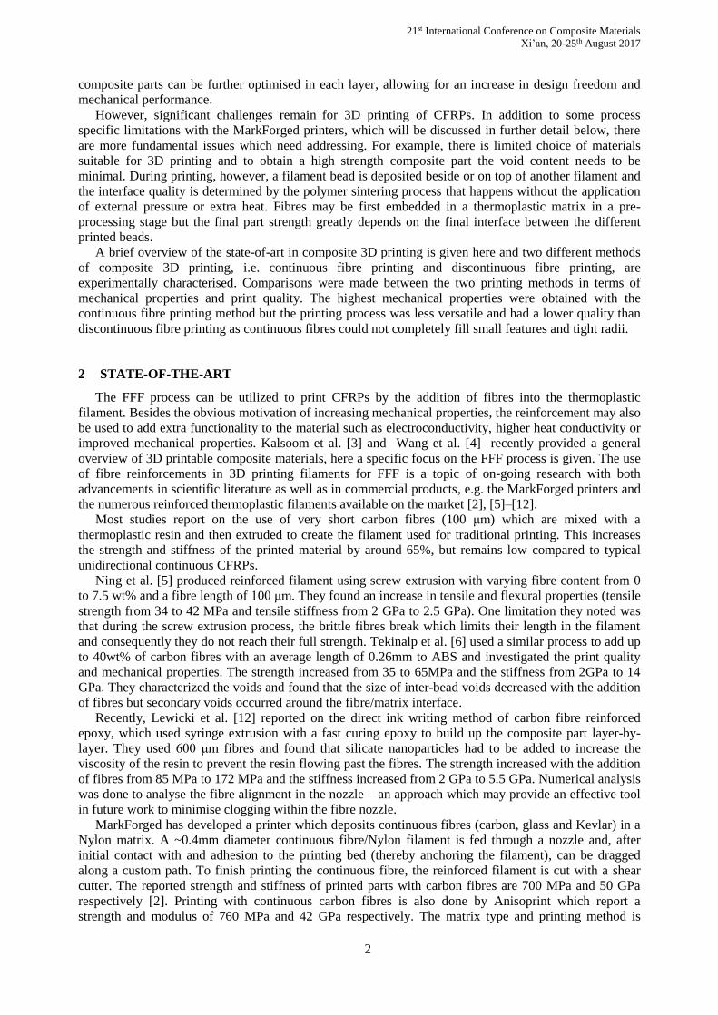
caused by the circumferential fill pattern, the tensile specimens were printed in an “oval racetrack” shape
to all for unidirectional 0° specimens to be extracted as shown in Figure 2. The dimensions of the tensile
specimens were 250 mm×15 mm×1 mm according to ASTM standards [17], where the bottom and top
layers of 0.125 mm thick were 100% triangular fill Nylon as discussed above. The estimated Vf of these
specimens was ~27%. Glass fibre tabs with a length of 25 mm were bonded to the specimen using an
epoxy adhesive and the tensile test was carried out at constant displacement rate of 2 mm/min. Strain
measurements were obtained from a video extensometer (IMETRUM, UK) and the load was obtained
from a 25 kN load cell (Instron).
Figure 2: Print schematic of unidirectional tensile and flexural specimens showing fibre path
A three-point bend fixture was used to obtain the flexural properties of the printed composite material
with a support rod radius of 4 mm and a support length of 128mm according to the ASTM D7264
standard [18]. The flexural specimens were manufactured in a similar approach as the tensile specimens,
with outer dimensions of 160 mm×11 mm×4 mm and all fibres orientated in the 0° orientation. A
constant displacement rate of 1 mm/min was used and the force and displacement was directly measured
from the machine with a 1 kN load cell.
To obtain the shear properties, the methodology proposed by Sun and Chung [19] was used for
uniaxial off-axis testing with oblique end-tabs. This creates a uniform state of stress from which the shear
properties can be obtained. The oblique angle is a function of the off-axis angle and the properties of the
composite, which were estimated to be E11 = 50 GPa, E22 = 0.38 GPa, G12 = 3.9 GPa and ν12 = 0.3.
The samples were cut under a 13° angle for which oblique end tabs with an angle of 21° were
required. The samples were tested using an electrical-mechanical tensile machine with a 10 kN load cell
and strain measurements were obtained from a 5MP LaVision DIC system.
Lastly, to assess the printing performance of the MarkOne printer and quality of the continuous fibre
deposited, benchmark parts were printed in the form of a 40×40 mm square, a 30°-60°-90° triangle
(85×50 mm) and a circle with a radius of 20? mm. The quality of the MarkOne printed parts was
investigated using these generic shapes and optical microscopy on printed samples.
3.2 Carbon fibre PLA filament characterization
The second composite printing method was done using a standard Prusa Mendel i3 based printer and a
PLA filament which was reinforced with chopped carbon fibres. The material was acquired from Proto-
Pasta and has 15 wt% carbon fibres added to the 1.75mm diameter filament [20]. In comparison to the
Mark One, this open-source printer allows for more control of the material deposition strategy, such as
21st International Conference on Composite Materials
Xi’an, 20-25th August 2017
5
printing tracks, extrusion rate and printing temperature. To characterize this printing technique, tensile
and flexural specimens were printed to determine the mechanical properties. Optical microscopy was
used to investigate the quality of these specimens.
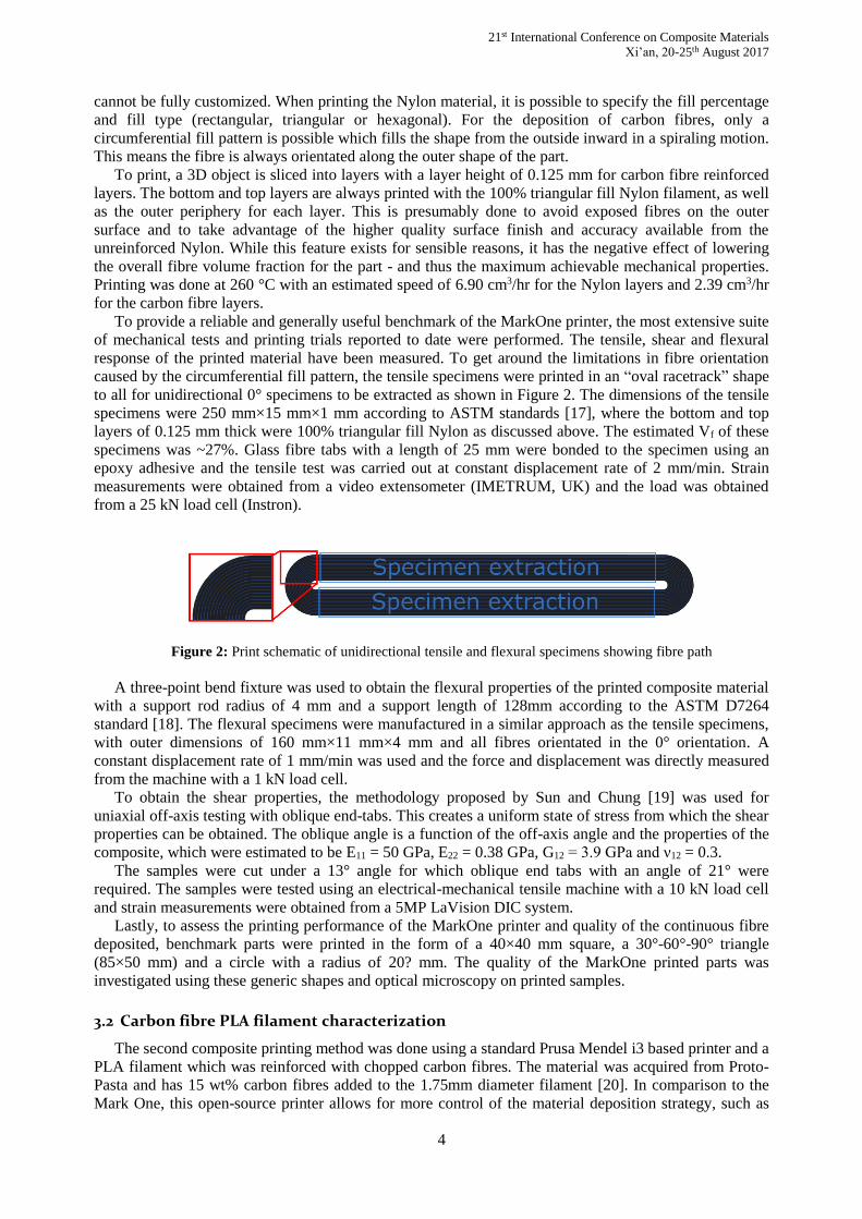
Tensile specimens were printed in dog-bone shapes according to the ASTM D638 [21], using a 0.4
mm nozzle diameter and a printing temperature of 205°C as recommended by the filament manufacturer.
The gauge section of the dog-bone specimens consists of tracks aligned in the 0° direction as shown in
Figure 3. The flexural specimens were printed as rectangles with dimensions 168×13×4 mm to match the
ASTM D7264 standard for three point bending [18] with a support length of 128 mm.
Figure 3: Dog-bone (top) and flexural (bottom) specimen printing fill patterns and specimen dimensions.
4 RESULTS
4.1 MarkOne continuous fibre printer characterization
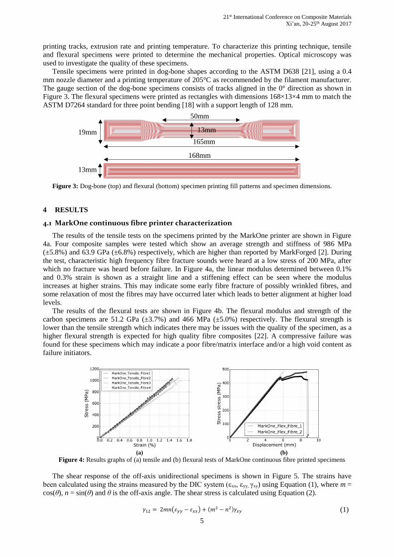
The results of the tensile tests on the specimens printed by the MarkOne printer are shown in Figure
4a. Four composite samples were tested which show an average strength and stiffness of 986 MPa
(±5.8%) and 63.9 GPa (±6.8%) respectively, which are higher than reported by MarkForged [2]. During
the test, characteristic high frequency fibre fracture sounds were heard at a low stress of 200 MPa, after
which no fracture was heard before failure. In Figure 4a, the linear modulus determined between 0.1%
and 0.3% strain is shown as a straight line and a stiffening effect can be seen where the modulus
increases at higher strains. This may indicate some early fibre fracture of possibly wrinkled fibres, and
some relaxation of most the fibres may have occurred later which leads to better alignment at higher load
levels.
The results of the flexural tests are shown in Figure 4b. The flexural modulus and strength of the
carbon specimens are 51.2 GPa (±3.7%) and 466 MPa (±5.0%) respectively. The flexural strength is
lower than the tensile strength which indicates there may be issues with the quality of the specimen, as a
higher flexural strength is expected for high quality fibre composites [22]. A compressive failure was
found for these specimens which may indicate a poor fibre/matrix interface and/or a high void content as
failure initiators.
(a) (b)
Figure 4: Results graphs of (a) tensile and (b) flexural tests of MarkOne continuous fibre printed specimens
The shear response of the off-axis unidirectional specimens is shown in Figure 5. The strains have
been calculated using the strains measured by the DIC system (εxx, εyy, γxy) using Equation (1), where m =
cos(θ), n = sin(θ) and θ is the off-axis angle. The shear stress is calculated using Equation (2).
𝛾12 = 2𝑚𝑛(𝜀𝑦𝑦 − 𝜀𝑥𝑥) + (𝑚2 − 𝑛2)𝛾𝑥𝑦 (1)
50mm
165mm
19mm 13mm
13mm
168mm

21st International Conference on Composite Materials
Xi’an, 20-25th August 2017
6
𝜏12 = −𝑚𝑛𝜎𝑥𝑥 (2)
The modulus has been determined from the initial linear part of the curve, which was found to be 2.3
GPa (±4.9%) and is lower than the expected value of 3.9 GPa used to determine the oblique end-test tab
angle. This may influence the results as a non-uniform state of stress occurs which can lead to premature
failure. The maximum shear stress was 31 MPa (± 15.8%) where it must be noted that one of the
specimens failed near the end-tab, which may explain the lower shear stress.
Figure 5: Shear response of shear test samples of MarkOne continuous fibre printed parts in the material (12)
coordinate system.
The printing quality of the MarkOne can be seen in Figure 6 with the printing of various generic
shapes. The MarkOne printer prints a fibre layer from the outside contour to the inside. For more
complex geometries, this causes large fibreless areas as shown in the triangular part. These fibreless areas
can be up to 2.5 mm×1 mm, which are recognized by the printing software and are filled with pure
Nylon, but this leads to a local weakness in the part. For a simpler shape, such as a square, a similar
effect is present in the corner regions on a smaller scale (1.5 mm×0.3 mm) but the areas are not filled
with Nylon here which leads to voids. For the circular shape, the fibres neatly follow the outside contour
with some small gaps with a width of 0.05 mm.
Figure 6: Benchmark prints for MarkOne continuous fibre printer with detail of corner radii.
Figure 7 is a micrograph of the cross section of one of the flexural test specimens showing the
multiple stacked layers. Within each layer distinct regions of nylon, fibre, and voids can be seen. The
fibre volume content is estimated to be 27% over the cross section, but a non-even distribution of fibres
can be seen. This is attributed the non-uniformity of the printing filament, which may also lead to the
creation of voids.

21st International Conference on Composite Materials
Xi’an, 20-25th August 2017
7
(a) (b)
Figure 7: Cross section of printed continuous fibre MarkForged part showing (a) structure from 3D printing
tracks and (b) detail of larger voids between tracks.
4.2 Carbon fibre PLA filament characterization
The result of the tensile tests and flexural tests on the carbon fibre PLA filaments are shown in Figure
8. The average tensile strength and stiffness are 56 MPa (±5.3%) and 8.4 GPa (±1.5%) respectively. The
strength is typical for unreinforced PLA but the stiffness increased by roughly a factor of two [23]. This
shows the fibres reinforce the material but do not reach their ultimate strengths. The flexural strength and
stiffness were found to be 85 MPa (±2.7%) and 6.8 GPa (±6.5%) respectively. For the reinforced PLA
filament, the flexural strength is higher than the tensile strength which is as expected for a high quality
composite part [22].
(a) (b)
Figure 8: Results graphs of (a) tensile and (b) flexural test results of carbon microfibre reinforced PLA.
Figure 9 shows the micrographs of parts printed with short carbon fibre reinforced PLA. The printed part
(Figure 9a) shows characteristic triangular voids between the printed tracks from the FFF process. The total void
content is estimated at 18% (3.5% of the triangular voids and 14.5% different voids). The printed part has a higher
void content than found in the filament, which was estimated at 8.2%. This can partially be attributed to the FFF
printing process creating additional triangular voids, but the percentage of random voids also increased from 8.2%
to 14.5% due to other methods which will need to be further identified.
Printed
track
Voids
Inter-track voids
Microfibre_PLA1_Tension
Microfibre_PLA2_Tension
Microfibre_PLA3_Tension
Microfibre_PLA1_Flex
Microfibre_PLA2_Flex
Microfibre_PLA3_Flex
Microfibre_PLA4_Flex

21st International Conference on Composite Materials
Xi’an, 20-25th August 2017
8
(a) (b)
Figure 9: Microstructure of (a) printed part and (b) filament of short carbon microfibre reinforced PLA
Figure 9b shows a 90° corner region of a printed part, showing a gap between the printed tracks of about 30 μm.
The short fibre reinforced filament shows a high void content, which may be attributed to the quality of the filament
and yet unidentified mechanism during the printing process, but the print quality in the corner is good where there is
a small gap between printed tracks and the short fibres follow the printing path. To minimize the void content,
improving the filament quality and altering the mesostructure as described by Rodgriquez et al. [24] may be
successful methods.
5 CONCLUSIONS & FUTURE WORKS
The properties of 3D printed composite parts have been investigated in this work. Previous studies
have mainly focused on printing of thermoplastic filaments reinforced with very short fibres (~0.1 mm)
or a filament with continuous fibre reinforcement. Both methods were assessed in this work, using a
MarkOne 3D printer to print continuous carbon fibre / Nylon composite specimens and a standard open-
source FFF printer to print carbon microfibre reinforced PLA. The tensile strength and stiffness of the
continuous fibre printed parts were 986 MPa and 64 GPa respectively, which is an order of magnitude
larger than the reinforced PLA printed parts (56 MPa and 8.4 GPa). A disadvantage of the continuous
fibre printer, however, is limited control over the placement of the fibre and the creation of voids when
printing more complex shapes. To overcome these disadvantages, a thermoplastic filament reinforced
with short fibres above the critical fibre length (~3 mm) is proposed. This would yield mechanical
properties similar to continuous fibre printer while maintaining the better processing qualities of short
fibre reinforced filament. This may enable new applications for high performance 3D printed parts
suitable for medical, aerospace, sport and rapid prototyping applications.
REFERENCES
[1] A. Mouritz, Introduction to Aerospace Materials, First edit. Cambridge, England: Woodhead Publishing
Ltd, 2012.
[2] Markforged, “High Strength 3D Printing With Continuous Fibres,” 2016. [Online]. Available:
https://markforged.com/. [Accessed: 01-Nov-2016].
[3] U. Kalsoom, P. N. Nesterenko, and B. Paull, “Recent developments in 3D printable composite materials,”
RSC Adv., vol. 6, no. 65, pp. 60355–60371, 2016.
[4] X. Wang, M. Jiang, Z. Zhou, J. Gou, and D. Hui, “3D printing of polymer matrix composites: A review and
prospective,” Compos. Part B Eng., vol. 110, pp. 442–458, 2017.
[5] F. Ning, W. Cong, J. Qiu, J. Wei, and S. Wang, “Additive manufacturing of carbon fiber reinforced
thermoplastic composites using fused deposition modeling,” Compos. Part B Eng., vol. 80, pp. 369–378,
2015.
[6] H. L. Tekinalp, V. Kunc, G. M. Velez-Garcia, C. E. Duty, L. J. Love, A. K. Naskar, C. A. Blue, and S.
Ozcan, “Highly oriented carbon fiber-polymer composites via additive manufacturing,” Compos. Sci.
Technol., vol. 105, pp. 144–150, 2014.
[7] R. Matsuzaki, M. Ueda, M. Namiki, T.-K. Jeong, H. Asahara, K. Horiguchi, T. Nakamura, A. Todoroki,
and Y. Hirano, “Three-dimensional printing of continuous-fiber composites by in-nozzle impregnation.,”
Sci. Rep., vol. 6, no. February, p. 23058, 2016.
[8] M. L. Shofner, K. Lozano, F. J. Rodríguez-Macías, and E. V. Barrera, “Nanofiber-reinforced polymers
prepared by fused deposition modeling,” J. Appl. Polym. Sci., vol. 89, no. 11, pp. 3081–3090, 2003.
[9] C. Mahajan and D. Cormier, “3D Printing of Carbon Fiber Composites With Preferentially Aligned Fibers,”
Printed track
Inter-track
triangular voids
~30 μm gap
21st International Conference on Composite Materials
Xi’an, 20-25th August 2017
9
Proc. 2015 Ind. Syst. Eng. Reserach Conf., 2015.
[10] J. Peng, T. L. Lin, and P. Calvert, “Orientation effects in freeformed short-fiber composites,” Compos. Part
A Appl. Sci. Manuf., vol. 30, pp. 133–138, 1999.
[11] F. Antonov, “Composites in 3D printing : trends , prospects and applications,” 2015.
[12] J. P. Lewicki, J. N. Rodriguez, C. Zhu, M. A. Worsley, A. S. Wu, Y. Kanarska, J. D. Horn, E. B. Duoss, J.
M. Ortega, W. Elmer, R. Hensleigh, R. A. Fellini, and M. J. King, “3D-Printing of Meso-structurally
Ordered Carbon Fiber/Polymer Composites with Unprecedented Orthotropic Physical Properties,” Sci.
Rep., vol. 7, no. December 2016, p. 43401, 2017.
[13] M. Elkington, C. Ward, and K. D. Potter, “Automated layup of sheet prepregs on complex moulds,” J. Adv.
Mater., vol. 3, no. 10, pp. 70–84, 2016.
[14] M. Such, C. Ward, and K. Potter, “Aligned Discontinuous Fibre Composites: A Short History,” J.
Multifunct. Compos., vol. 2, no. 3, pp. 155–168, 2014.
[15] M. R. Piggott, M. Ko, and H. Y. Chuang, “Aligned short-fibre reinforced thermosets: Experiments and
analysis lend little support for established theory,” Compos. Sci. Technol., vol. 48, no. 1–4, pp. 291–299,
1993.
[16] H. Yu, K. D. Potter, and M. R. Wisnom, “A novel manufacturing method for aligned discontinuous fibre
composites (High Performance-Discontinuous Fibre method),” Compos. Part A Appl. Sci. Manuf., vol. 65,
pp. 175–185, 2014.
[17] ASTM International, “D3039/D3039M: Standard test method for tensile properties of polymer matrix
composite materials.” pp. 1–13, 2014.
[18] ASTM International, “D7264/D7264M-07: Standard Test Method for Flexural Properties of Polymer
Matrix Composite Materials 1.” pp. 1–11, 2010.
[19] C. T. Sun and I. Chung, “An oblique end-tab design for testing off-axis composite specimens,” Composites,
vol. 24, no. 8, pp. 619–623, 1993.
[20] ProtoPlant, “Carbon Fiber PLA.” [Online]. Available: www.proto-pasta.com.
[21] ASTM International, “D638: Standard test method for tensile properties of plastics.” pp. 1–16, 2013.
[22] M. R. Wisnom, “The Relationship between Tensile and Flexural Strength of Unidirectional Composites,” J.
Compos. Mater., vol. 26, no. 8, pp. 1173–1180, 1992.
[23] A. Lanzotti, M. Grasso, G. Staiano, and M. Martorelli, “The impact of process parameters on mechanical
properties of parts fabricated in PLA with an open-source 3-D printer,” Rapid Prototyp. J., vol. 21, no. 5,
pp. 604–617, 2015.
[24] J. F. Rodriguez, J. P. Thomas, J. E. Renaud, J. F. Rodriguez, J. P. Thomas, J. E. Renaud, J. F. Rodriguez, J.
P. Thomas, and J. E. Renaud, “Characterization of the mesostructure of fused-deposition acrylonitrile-
butadiene-styrene materials,” 2011.
Related Documents