RE 51468, edition: 2014-08, Bosch Rexroth AG Block mounting filter, for sandwich plate mounting Features The sandwich plate filters are used in hydraulic systems for separating solid materials from fluids and lubricating oils. They are intended for installation in vertical stacking (sandwich plate design). They distinguish themselves by the following: ▶ Filter for sandwich plate mounting, filter bowl left or right ▶ Special highly efficient filter materials ▶ Filtration of very fine particles and high dirt holding capacity across a broad pressure differential range ▶ High collapse resistance of the filter elements ▶ By default equipped with mechanical optical mainte- nance indicator with memory function ▶ Various optional electronic switching elements, modular design ▶ Porting pattern according to ISO 4401-03-02-0-05 (size 6) or ISO 4401-05-04-0-05 (size 10). ▶ High filtration performance due to the tangential cyclone-effect flow path Contents Features 1 Ordering code filter 2 Preferred types 3 Ordering code accessories 4 Symbols 5 Function, section 6 Technical data 7, 8 Compatibility with hydraulic fluids 8 Characteristic curves 9, 10 Dimensions 11 … 13 Maintenance indicator 14 Ordering code spare parts 15 … 17 Assembly, commissioning, maintenance 18 Tightening torques 19 Directives and standardization 19, 20 ▶ Size according to Bosch Rexroth standard: 06/025 to 10/125 ▶ Component series 2X ▶ Nominal pressure 320 bar [4641 psi] ▶ Connection according to ISO4401 NG6 and NG10 ▶ Operating temperature ‒10 °C to +100 °C [14 °F to 212 °F] RE 51468 Issue: 2014-08 HAD7824_d Type 320PZR06/025 to 10/125; 320PZL06/025

Welcome message from author
This document is posted to help you gain knowledge. Please leave a comment to let me know what you think about it! Share it to your friends and learn new things together.
Transcript
Contents
Features 1Contents 1Ordering code 2Filters 2Preferred types 3Ordering code 3Accessories (dimensions in mm [in]) 3Ordering code 4Accessories 4(dimensions in mm [in]) 4Electronic switching element for maintenance indicators 4Mating connectors 4Symbols 5Function, section 6Technical data 7(For applications outside these parameters, please consult us!) 7Technical data (For applications outside these parameters, please consult us!) 8Compatibility with hydraulic fluids 8Characteristic curves H3PZ… 9(measured with mineral oil HLP46 according to DIN 51524) 9Characteristic curves H10PZ… 10(measured with mineral oil HLP46 according to DIN 51524) 10Dimensions: NG025 (dimensions in mm [in]) 11Dimensions: NG025 (dimensions in mm [in]) 12Dimensions: NG075 125 (dimensions in mm [in]) 13Maintenance indicator (dimensions in mm [in]) 14Ordering code 15Spare parts 15Ordering code 16Spare parts 16Ordering code 17Spare parts 17Assembly, commissioning, maintenance 18Tightening torque (dimensions in mm [in]) 19Directives and standardization 19Directives and standardization 20
RE 51468, edition: 2014-08, Bosch Rexroth AG
Block mounting filter, for sandwich plate mounting
Features
The sandwich plate filters are used in hydraulic systems for separating solid materials from fluids and lubricating oils. They are intended for installation in vertical stacking (sandwich plate design).
They distinguish themselves by the following: ▶ Filter for sandwich plate mounting, filter bowl left or
right ▶ Special highly efficient filter materials ▶ Filtration of very fine particles and high dirt holding
capacity across a broad pressure differential range ▶ High collapse resistance of the filter elements ▶ By default equipped with mechanical optical mainte-
nance indicator with memory function ▶ Various optional electronic switching elements, modular
design ▶ Porting pattern according to ISO 4401-03-02-0-05
(size 6) or ISO 4401-05-04-0-05 (size 10). ▶ High filtration performance due to the tangential
cyclone-effect flow path
Contents
Features 1Ordering code filter 2Preferred types 3 Ordering code accessories 4Symbols 5Function, section 6Technical data 7, 8Compatibility with hydraulic fluids 8Characteristic curves 9, 10Dimensions 11 … 13 Maintenance indicator 14Ordering code spare parts 15 … 17Assembly, commissioning, maintenance 18Tightening torques 19Directives and standardization 19, 20
▶ Size according to Bosch Rexroth standard: 06/025 to 10/125
▶ Component series 2X ▶ Nominal pressure 320 bar [4641 psi] ▶ Connection according to ISO4401 NG6 and NG10 ▶ Operating temperature ‒10 °C to +100 °C [14 °F to 212 °F]
RE 51468 Issue: 2014-08
HAD7824_d
Type 320PZR06/025 to 10/125; 320PZL06/025
2/20 320PZR06/025-2X … 10/125-2X; 320PZL06/025-2X | Block mounting filter
Bosch Rexroth AG, RE 51468, edition: 2014-08
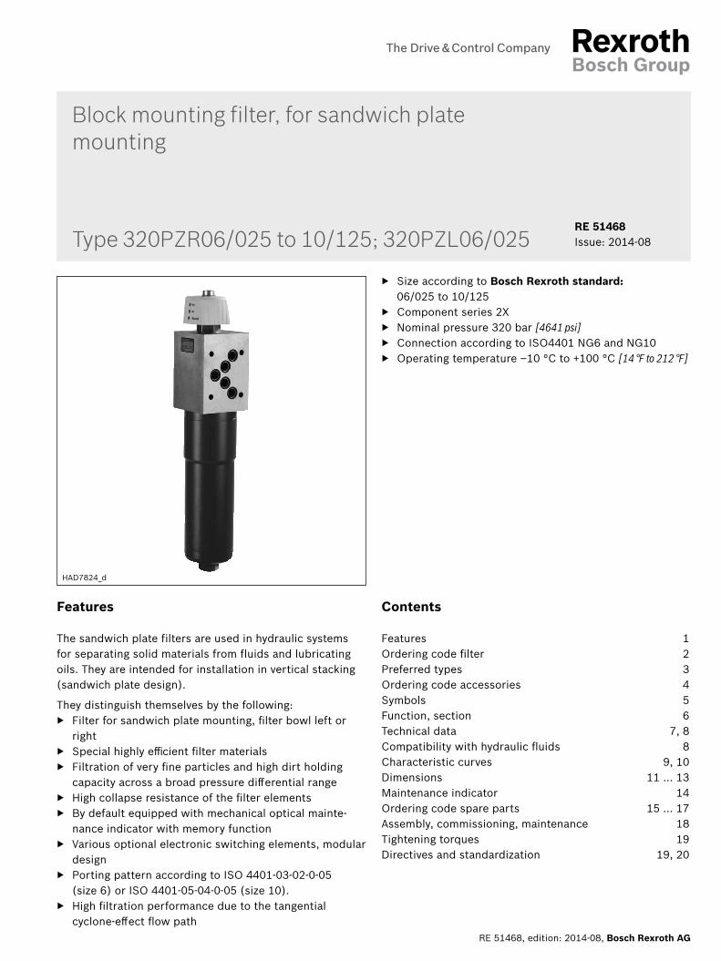
Ordering code Filters
Series01 Sandwich plate filter 320 bar [4641 psi] 320PZ
Filter bowl position02 Right R
Left L
Size03 PZR… 06/025
10/07510/125
PZL… 06/025
04 Component series 20 … 29 (20 … 29: unchanged installation and connection dimensions) 2X
Filter rating in μm05 Absolute (ISO 16889) Glass fiber material, not cleanable H3PZ
H6PZ H10PZ H20PZ
Pressure differential06 Max. admissible pressure differential of the filter element 330 bar [4786 psi], without bypass valve B00
Maintenance indicator07 Maintenance indicator, mech./optical, switching pressure 5.0 bar [72.5 psi] V5.0
Maintenance indicator, mech./optical, switching pressure 8.0 bar [116 psi] V8.0
Seal08 NBR seal M
FKM seal V
Supplementary information09 Manufacturer's inspection certificate M according to DIN 55350 T18 Z1
01 02 03 04 05 06 07 08 09
320PZ ‒ 2X / B00 ‒ ‒ ‒
Order example:320PZR10/125-2X/H10PZB00-V8,0-M
Material no.: R928053411
Further versions are available on request.
Block mounting filter | 320PZR06/025-2X … 10/125-2X; 320PZL06/025-2X 3/20
RE 51468, edition: 2014-08, Bosch Rexroth AG
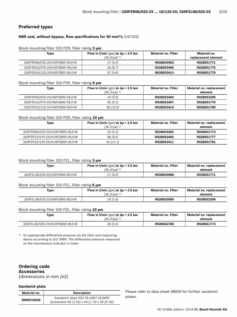
Preferred types
NBR seal, without bypass, flow specifications for 30 mm2/s [142 SUS]
Block mounting filter 320 PZR, filter rating 3 μmType Flow in l/min [gpm] at Δp = 2.5 bar
[36.25 psi] 1)Material no. Filter Material no.
replacement element320PZR06/025-2X/H3PZB00-V8,0-M 17 [4.5] R928053403 R928051771320PZR10/075-2X/H3PZB00-V8,0-M 33 [8.7] R928053406 R928051775320PZR10/125-2X/H3PZB00-V8,0-M 37 [9.8] R928053413 R928051779
Block mounting filter 320 PZR, filter rating 6 μmType Flow in l/min [gpm] at Δp = 2.5 bar
[36.25 psi] 1)Material no. Filter Material no. replacement
element320PZR06/025-2X/H6PZB00-V8,0-M 19 [5.0] R928053404 R928053299320PZR10/075-2X/H6PZB00-V8,0-M 35 [9.2] R928053407 R928051776320PZR10/125-2X/H6PZB00-V8,0-M 38 [10.0] R928053414 R928051780
Block mounting filter 320 PZR, filter rating 10 μmType Flow in l/min [gpm] at Δp = 2.5 bar
[36.25 psi] 1)Material no. Filter Material no. replacement
element320PZR06/025-2X/H10PZB00-V8,0-M 20 [5.3] R928053402 R928051773320PZR10/075-2X/H10PZB00-V8,0-M 36 [9.5] R928053405 R928051777320PZR10/125-2X/H10PZB00-V8,0-M 42 [11.1] R928053411 R928051781
Block mounting filter 320 PZL, filter rating 3 μmType Flow in l/min [gpm] at Δp = 2.5 bar
[36.25 psi] 1)Material no. Filter Material no. replacement
element320PZL06/025-2X/H3PZB00-V8,0-M 17 [4.5] R928053998 R928051771
Block mounting filter 320 PZL, filter rating 6 μmType Flow in l/min [gpm] at Δp = 2.5 bar
[36.25 psi] 1)Material no. Filter Material no. replacement
element320PZL06/025-2X/H6PZB00-V8,0-M 19 [5.0] R928053999 R928053299
Block mounting filter 320 PZL, filter rating 10 μmType Flow in l/min [gpm] at Δp = 2.5 bar
[36.25 psi] 1)Material no. Filter Material no. replacement
element320PZL06/025-2X/H10PZB00-V8,0-M 20 [5.3] R928053768 R928051773
1) An appropriate differential pressure via the filter and measuring device according to ISO 3968. The differential pressure measured on the maintenance indicator is lower.
Material no. Description
R900516530 Sandwich plate HSZ 06 A007-3X/M00 (Dimension 65 [2.56] x 44 [1.73] x 20 [0.79])
Sandwich plate
Ordering code Accessories (dimensions in mm [in])
Please refer to data sheet 48050 for further sandwich plates.

������������
����
���
�����
����
���
����
���
��� ��
����
�����������
4/20 320PZR06/025-2X … 10/125-2X; 320PZL06/025-2X | Block mounting filter
Bosch Rexroth AG, RE 51468, edition: 2014-08
Ordering code Accessories (dimensions in mm [in])
Electronic switching element for maintenance indicators
Maintenance indicator01 electronic switching element WE
Type of signal02 1 switching point 1SP
2 switching points, 3 LED 2SP2 switching points, 3 LED and signal suppression up to 30 °C [86 °F] 2SPSU
Connector03 Round plug-in connection M12 x 1, 4-pole M12x1
Rectangular plug-in connection, 2-pole, design A according to EN-175301-803 EN175301-803
01 02 03
WE – –
Material numbers of the electronic switching elementsMaterial no. Type Signal Switching points Connector LEDR928028409 WE-1SP-M12x1 Changeover 1
M12x1
NoR928028410 WE-2SP-M12x1 Normally open (at 75%) /
normally closed contact (at 100%)
2 3 piecesR928028411 WE-2SPSU-M12x1
R928036318 WE-1SP-EN175301-803 Normally closed contact 1 EN 175301-803 No
Order example: Block mounting filter for sandwich plate mounting with mechanical optical maintenance indicator for pnominal = 320 bar [4641 psi] without bypass valve, size 10/125, with filter element 10 μm and electronic switching element M12x1 with 1 switching point.Filter with mech. optical 320PZR10/125-2X/H10PZB00-V8,0-M Material no. R928053411 maintenance indicator:Switching element: WE-1SP-M12x1 Material no. R928028409Mating connector: Mating connector suitable for K24 4-pin, M12x1 Material no. R900031155
Mating connectors
Mating connector suitable for K24 4-pole, M12x1 with screw connection, cable gland Pg9.
Material no. R900031155
for electronic switching element with round plug-in connection M12x1
Mating connector suitable for K24-3m 4-pole, M12x1 with potted-in PVC cable, 3 m long. Line cross-section: 4 x 0.34 mm2
Core marking: 1 brown 2 white 3 blue 4 blackMaterial no. R900064381
For more round plug-in connections and technical data refer to data sheet 08006.
���������
����
����
�������
�
����� ����
��������
����� �������
��
����
����
��� � �
� � �
Block mounting filter | 320PZR06/025-2X … 10/125-2X; 320PZL06/025-2X 5/20
RE 51468, edition: 2014-08, Bosch Rexroth AG
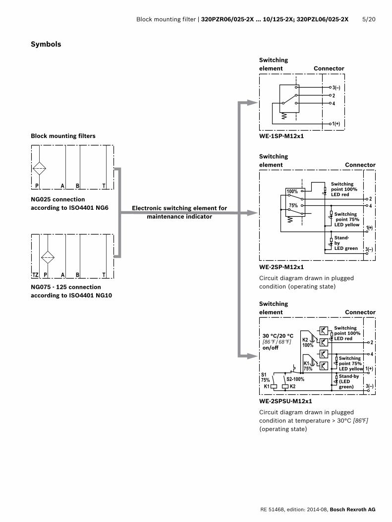
Block mounting filters
NG025 connection according to ISO4401 NG6
NG075 - 125 connection according to ISO4401 NG10
Symbols
Electronic switching element for maintenance indicator
WE-1SP-M12x1
Switching element Connector
Switching point 100% LED red
Switching point 75% LED yellowStand-by (LED green)
30 °C/20 °C[86 °F / 68 °F]on/off
WE-2SPSU-M12x1
Circuit diagram drawn in plugged condition at temperature > 30°C [86°F] (operating state)
WE-2SP-M12x1
Circuit diagram drawn in plugged condition (operating state)
Switching element Connector
Switching point 100% LED red
Switching point 75% LED yellow
Stand- by LED green
Switching element Connector
�
�
�
�
�
6/20 320PZR06/025-2X … 10/125-2X; 320PZL06/025-2X | Block mounting filter
Bosch Rexroth AG, RE 51468, edition: 2014-08
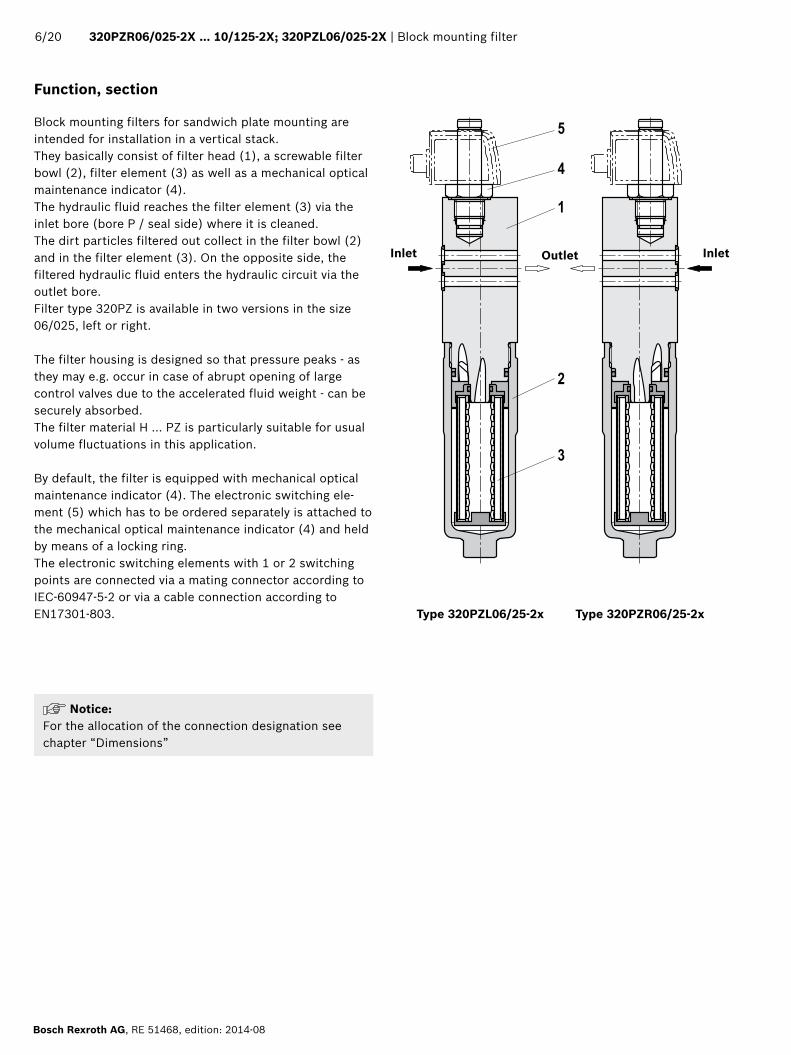
Function, section
Block mounting filters for sandwich plate mounting are intended for installation in a vertical stack. They basically consist of filter head (1), a screwable filter bowl (2), filter element (3) as well as a mechanical optical maintenance indicator (4).The hydraulic fluid reaches the filter element (3) via the inlet bore (bore P / seal side) where it is cleaned.The dirt particles filtered out collect in the filter bowl (2) and in the filter element (3). On the opposite side, the filtered hydraulic fluid enters the hydraulic circuit via the outlet bore.Filter type 320PZ is available in two versions in the size 06/025, left or right.
The filter housing is designed so that pressure peaks - as they may e.g. occur in case of abrupt opening of large control valves due to the accelerated fluid weight - can be securely absorbed.The filter material H ... PZ is particularly suitable for usual volume fluctuations in this application.
By default, the filter is equipped with mechanical optical maintenance indicator (4). The electronic switching ele-ment (5) which has to be ordered separately is attached to the mechanical optical maintenance indicator (4) and held by means of a locking ring.The electronic switching elements with 1 or 2 switching points are connected via a mating connector according to IEC-60947-5-2 or via a cable connection according to EN17301-803. Type 320PZL06/25-2x Type 320PZR06/25-2x
InletInlet Outlet
Notice: For the allocation of the connection designation see chapter “Dimensions”

Block mounting filter | 320PZR06/025-2X … 10/125-2X; 320PZL06/025-2X 7/20
RE 51468, edition: 2014-08, Bosch Rexroth AG
Technical data (For applications outside these parameters, please consult us!)
GeneralInstallation position Sandwich plate mounting Ambient temperature range °C [°F] ‒10 … +65 [+14 … +149] (short-term … ‒30 [‒22])Storage conditions – NBR seal °C [°F] ‒40 … +65 [‒40 … +149]; max. relative air humidity 65%
‒FKM seal °C [°F] ‒20 … +65[‒4 … +149]; max. relative air humidity 65%Weight NS 06/025 10/075 10/125
kg[lbs]
3.5[7.7]
6.5[14.4]
7.2[15.9]
Volume NS 06/025 10/075 10/125l
[US gal]0.14
[0.037]0.35
[0.092]0.48
[0.127]Material –Filter head Ductile iron
–Filter bowl Steel– Seals NBR or FKM– Optical maintenance indicator V5.0; V8.0 Brass‒ Electronic switching element Plastic PA6
Surface requirement tank hydraulic block
‒ Roughness depth Rz max. μm 4‒ Levelness tE max. mm 0.01/100
HydraulicMaximum operating pressure bar [psi] 320 [4641]Hydraulic fluid temperature range °C [°F] –10 … +100 [+14 … +212]Minimum conductivity of the medium pS/m 300Fatigue strength according to ISO 10771 Load cycles > 106 with max. operating pressureType of pressure measurement of the maintenance indicator Pressure differentialAssignment: Response pressure of the maintenance indicator / cracking pressure of the bypass valve
Response pressure of the maintenance indicator
Cracking pressure of the bypass valve
bar [psi]5.0 ± 0.5 [72 ± 7]
not possible8.0 ± 0.8 [116 ± 11.6]
Electric (electronic switching element)Electrical connection Round plug-in connection M12x1, 4-pole Standard connection
EN 175301-803Version WE-1SP-
M12x1 WE-2SP-M12x1
WE-2SPSU-M12x1
WE-1SP-EN175301-803
Contact load, direct voltage Amax. 1Voltage range Vmax. 150 (AC/
DC)10-30 (DC) 250 (AC)/200 (DC)
max. switching power with resistive load W 20 70Switching type – 75% signal – Normally open contact –
– 100% signal Changeover Normally closed contact Normally closed contact
– 2SPSU Signal interconnection at 30 °C[86 °F],
return switching at 20 °C [68 °F]
Display via LEDs in the electronic switching element 2SP... Stand-by (LED green); 75% switching point (LED yellow)100% switching point (LED red)
Protection class according to EN 60529 IP IP 67 IP 65Ambient temperature range °C [°F] –25 … +85 [–13 … +185]For direct voltage above 24 V, spark extinguishing is to be provided for protecting the switching contacts.Weight ‒ electronic switching element kg [lbs] 0.1 [0.22]

8/20 320PZR06/025-2X … 10/125-2X; 320PZL06/025-2X | Block mounting filter
Bosch Rexroth AG, RE 51468, edition: 2014-08
Technical data (For applications outside these parameters, please consult us!)
Filter elementGlass fiber material H...PZ Single-use element on the basis of inorganic fiber
Filtration ratio according to ISO 16889 up to
Δp = 5 bar [72.5 psi]
Achievable oil cleanliness according to ISO 4406 [SAE-AS 4059]
Particle separation H20PZ β20(c) ≥ 200 19/16/12 – 22/17/14H10PZ β10(c) ≥ 200 17/14/10 – 21/16/13
H6PZ β6(c) ≥ 200 15/12/10 – 19/14/11H3PZ β5(c) ≥ 200 13/10/8 – 17/13/10
admissible pressure differential B00 bar [psi] 330 [4786]
Compatibility with hydraulic fluids
Hydraulic fluid Classification Suitable sealing materials StandardsMineral oil HLP NBR DIN 51524Biodegradable – insoluble in water HETG NBR
VDMA 24568HEES FKM
– soluble in water HEPG FKM VDMA 24568Flame-resistant – water-free HFDU, HFDR FKM VDMA 24317
– containing water HFAS NBRDIN 24320
HFAE NBRHFC NBR VDMA 24317
Important information on hydraulic fluids: ▶ For more information and data on the use of other hydraulic fluids, please refer to data sheet 90220 or contact us!
▶ Flame-resistant – containing water: Due to possible chemical reactions with materials or surface coatings of machine and system components, the service life with these hydraulic fluids may be less than expected.
Filter materials made of filter paper (cellulose) may not be used, filter elements with glass fiber material have to be used instead.
▶ Bio-degradable: If filter materials made of filter paper are used, the filter life may be shorter than expected due to material incompatibility and swelling.
� ��
���
���
���
���
���
����
���
����
����
����
����
����
�� ��
���������
��
������
�� ��
���
���
���
���
���
����
���
����
����
����
����
����
�� ��
����������
��
�������
�� ��
���
���
���
���
���
����
����
�� �� ��
����
��
��������������������
�������
����
����
����
����
����
�������������������������
���������������������������
Block mounting filter | 320PZR06/025-2X … 10/125-2X; 320PZL06/025-2X 9/20
RE 51468, edition: 2014-08, Bosch Rexroth AG
320PZR06/025; 320PZL06/025 320PZR10/075
Pres
sure
diff
eren
tial i
n ba
r [p
si] →
Pres
sure
diff
eren
tial i
n ba
r [p
si] →
Flow in l/min [gpm] → Flow in l/min [gpm] →
320PZR10/125
Pres
sure
diff
eren
tial i
n ba
r [p
si] →
Flow in l/min [gpm] →
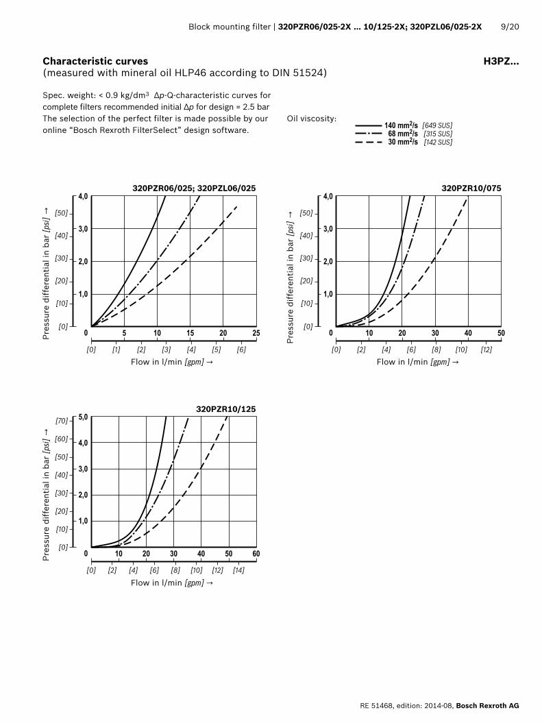
Characteristic curves H3PZ…(measured with mineral oil HLP46 according to DIN 51524)
Oil viscosity:
Spec. weight: < 0.9 kg/dm3 Δp-Q-characteristic curves for complete filters recommended initial Δp for design = 2.5 bar The selection of the perfect filter is made possible by our online “Bosch Rexroth FilterSelect” design software.
� ��
���
���
���
���
���
����
���
����
����
����
����
����
�� ��
���������
��
������
�� ��
���
���
���
���
���
����
���
����
����
����
����
����
�� ��
����������
��
�������
�� ��
���
���
���
���
���
����
����
�� �� ��
����
��
��������������������
�������
����
����
����
����
����
�������������������������
���������������������������
10/20 320PZR06/025-2X … 10/125-2X; 320PZL06/025-2X | Block mounting filter
Bosch Rexroth AG, RE 51468, edition: 2014-08
320PZR06/025; 320PZL06/025 320PZR10/075
Pres
sure
diff
eren
tial i
n ba
r [p
si] →
Pres
sure
diff
eren
tial i
n ba
r [p
si] →
Flow in l/min [gpm] → Flow in l/min [gpm] →
320PZR10/125
Pres
sure
diff
eren
tial i
n ba
r [p
si] →
Flow in l/min [gpm] →
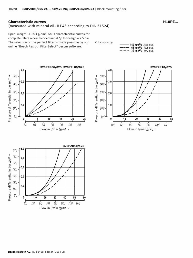
Characteristic curves H10PZ…(measured with mineral oil HLP46 according to DIN 51524)
Oil viscosity:
Spec. weight: < 0.9 kg/dm3 Δp-Q-characteristic curves for complete filters recommended initial Δp for design = 2.5 bar The selection of the perfect filter is made possible by our online “Bosch Rexroth FilterSelect” design software.
��
��
���� �����
�� ��
����
��
�
�
��
��
����
��
�� ��
��
��
����
����
��
Block mounting filter | 320PZR06/025-2X … 10/125-2X; 320PZL06/025-2X 11/20
RE 51468, edition: 2014-08, Bosch Rexroth AG
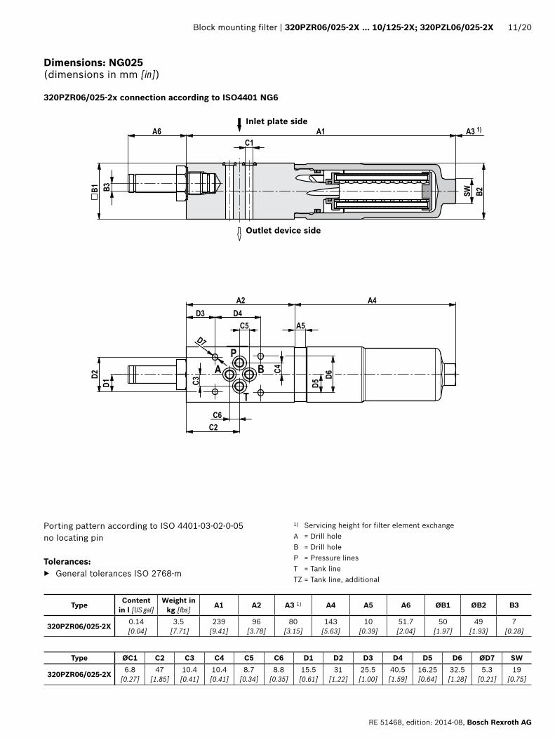
1) Servicing height for filter element exchange A = Drill holeB = Drill holeP = Pressure linesT = Tank lineTZ = Tank line, additional
Dimensions: NG025 (dimensions in mm [in])
320PZR06/025-2x connection according to ISO4401 NG6
Porting pattern according to ISO 4401-03-02-0-05no locating pin
Tolerances: ▶ General tolerances ISO 2768-m
Type Content in l [US gal]
Weight in kg [lbs] A1 A2 A3 1) A4 A5 A6 ØB1 ØB2 B3
320PZR06/025-2X 0.14 [0.04]
3.5 [7.71]
239 [9.41]
96 [3.78]
80 [3.15]
143 [5.63]
10 [0.39]
51.7 [2.04]
50 [1.97]
49 [1.93]
7 [0.28]
Type ØC1 C2 C3 C4 C5 C6 D1 D2 D3 D4 D5 D6 ØD7 SW
320PZR06/025-2X 6.8 [0.27]
47 [1.85]
10.4 [0.41]
10.4 [0.41]
8.7 [0.34]
8.8 [0.35]
15.5 [0.61]
31 [1.22]
25.5 [1.00]
40.5 [1.59]
16.25 [0.64]
32.5 [1.28]
5.3 [0.21]
19 [0.75]
Outlet device side
Inlet plate side
��
��
���������
����
��
���
�
�
�
��
��
�� ��
��
����
��
��
�� ��
��
��
��
12/20 320PZR06/025-2X … 10/125-2X; 320PZL06/025-2X | Block mounting filter
Bosch Rexroth AG, RE 51468, edition: 2014-08
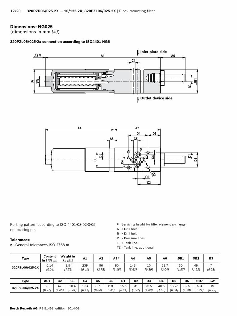
Dimensions: NG025 (dimensions in mm [in])
320PZL06/025-2x connection according to ISO4401 NG6
Outlet device side
Inlet plate side
1) Servicing height for filter element exchange A = Drill holeB = Drill holeP = Pressure linesT = Tank lineTZ = Tank line, additional
Porting pattern according to ISO 4401-03-02-0-05no locating pin
Tolerances: ▶ General tolerances ISO 2768-m
Type Content in l [US gal]
Weight in kg [lbs] A1 A2 A3 1) A4 A5 A6 ØB1 ØB2 B3
320PZL06/025-2X 0.14 [0.04]
3.5 [7.71]
239 [9.41]
96 [3.78]
80 [3.15]
143 [5.63]
10 [0.39]
51.7 [2.04]
50 [1.97]
49 [1.93]
7 [0.28]
Type ØC1 C2 C3 C4 C5 C6 D1 D2 D3 D4 D5 D6 ØD7 SW
320PZL06/025-2X 6.8 [0.27]
47 [1.85]
10.4 [0.41]
10.4 [0.41]
8.7 [0.34]
8.8 [0.35]
15.5 [0.61]
31 [1.22]
25.5 [1.00]
40.5 [1.59]
16.25 [0.64]
32.5 [1.28]
5.3 [0.21]
19 [0.75]

��
��
�
�
�
�
����
��
��
��
��
�� �� �����
�� ��
�� ��
��
��
����
�
��
��
��
��
��
���� ��
Block mounting filter | 320PZR06/025-2X … 10/125-2X; 320PZL06/025-2X 13/20
RE 51468, edition: 2014-08, Bosch Rexroth AG
Dimensions: NG075 125 (dimensions in mm [in])
320PZR10/075-2X … 320PZR10/125-2X connection according to ISO4401 NG10
Outlet device side
Inlet plate side
1) Servicing height for filter element exchange A = Drill holeB = Drill holeP = Pressure linesT = Tank lineTZ = Tank line, additional
Porting pattern according to ISO 4401-05-04-0-05 no locating pin
Tolerances: ▶ General tolerances ISO 2768-m
Type Content in l [US gal]
Weight in kg [lbs] A1 A2 A3 1) A4 A5 A6 ØB1 ØB2 B3 B4 ØC1 C2 C3
320PZR10/075-2X 0.35 [0.09]
6.5 [14.33]
245 [9.65] 100
[3.94]80
[3.15]
145 [5.71] 10.5
[0.41]51.7
[2.04]70
[2.76]69
[2.72]7.5
[0.30]5
[0.20]10.5
[0.41]28.2
[1.11]13.5
[0.53]320PZR10/125-2X 0.48
[0.13]7.2
[15.87]314
[12.36]214
[8.43]
Type C4 C5 C6 C7 C8 C9 D1 D2 D3 D4 D5 D6 ØD7 SW320PZR10/075-2X 23.8
[0.94]34.1
[1.34]47.6
[1.87]16.7
[0.66]1.6
[0.06]9.5
[0.37]23
[0.91]46
[1.81]25
[0.98]54
[2.13]23
[0.91]46
[1.81]6.6
[0.26]24
[0.94]320PZR10/125-2X

��
����
�������
���������
�����������
�����������
�����������
����
�����
������
�����
����
�����
��
����� �
�
�
�
�
�
��
�����������
����
������
�
���������
�����������
�����������
���������
����
�����
������
�����
����
�����
������
���
����� �
�
�
�
�
�
�
��
�������
14/20 320PZR06/025-2X … 10/125-2X; 320PZL06/025-2X | Block mounting filter
Bosch Rexroth AG, RE 51468, edition: 2014-08
Maintenance indicator (dimensions in mm [in])
Pressure differential indicator with mounted switching element M12x1
Pressure differential indicator with mounted switching element EN-175301-803
1 Mechanical optical maintenance indicator; max. tightening torque MA max = 50 Nm [36.88 lb-ft]
2 Switching element with locking ring for electrical maintenance indicator (rotatable by 360°);round plug-in connection M12x1, 4-pole
3 Switching element with locking ring for electrical maintenance indicator (rotatable by 360°);rectangular plug-in connection EN175301-803
4 Housing with three LEDs: 24 V = green: Stand-by yellow: Switching point 75% red: Switching point 100%
5 Visual indicator with memory function
6 Locking ring DIN 471-16x1, material no. R9000039237 Name plate
Notices: Representation contains mechanical optical maintenance indicator (1) and electronic switching element (2) (3).
Block mounting filter | 320PZR06/025-2X … 10/125-2X; 320PZL06/025-2X 15/20
RE 51468, edition: 2014-08, Bosch Rexroth AG
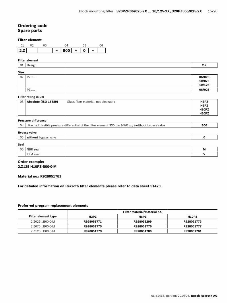
Ordering codeSpare parts
Filter element
Filter element01 Design 2.Z
Size02 PZR… 06/025
10/07510/125
PZL… 06/025
Filter rating in μm03 Absolute (ISO 16889) Glass fiber material, not cleanable H3PZ
H6PZ H10PZ H20PZ
Pressure difference04 Max. admissible pressure differential of the filter element 330 bar [4786 psi] (without bypass valve B00
Bypass valve05 without bypass valve 0
Seal06 NBR seal M
FKM seal V
01 02 03 04 05 06
2.Z ‒ B00 ‒ 0 ‒
Order example:2.Z125 H10PZ-B00-0-M
Material no.: R928051781
For detailed information on Rexroth filter elements please refer to data sheet 51420.
Preferred program replacement elements
Filter element type
Filter material/material no.H3PZ H6PZ H10PZ
2.Z025…B00-0-M R928051771 R928053299 R9280517732.Z075…B00-0-M R928051775 R928051776 R9280517772.Z125…B00-0-M R928051779 R928051780 R928051781

16/20 320PZR06/025-2X … 10/125-2X; 320PZL06/025-2X | Block mounting filter
Bosch Rexroth AG, RE 51468, edition: 2014-08
Ordering codeSpare parts
01 Maintenance indicator W
02 Mechanical optical indicator O
Version03 Pressure differential, modular design D01
Switching pressure04 5.0 bar [72.5 psi] 5.0
8.0 bar [116.0 psi] 8.0
Seal05 NBR seal M
FKM seal V
Max. operating pressure06 Switching pressure 5.0 bar [72.5 psi], 450 bar [6527 psi] 450
Switching pressure 8.0 bar [116.0 psi], 450 bar [6527 psi] 450
01 02 03 04 05 06
W O – D01 – – –
Mechanical optical maintenance indicator
Material no. DescriptionR928025313 WO-D01-5.0-M-450R901066235 WO-D01-5.0-V-450R928038785 WO-D01-8.0-M-450R928038784 WO-D01-8.0-V-450
Block mounting filter | 320PZR06/025-2X … 10/125-2X; 320PZL06/025-2X 17/20
RE 51468, edition: 2014-08, Bosch Rexroth AG
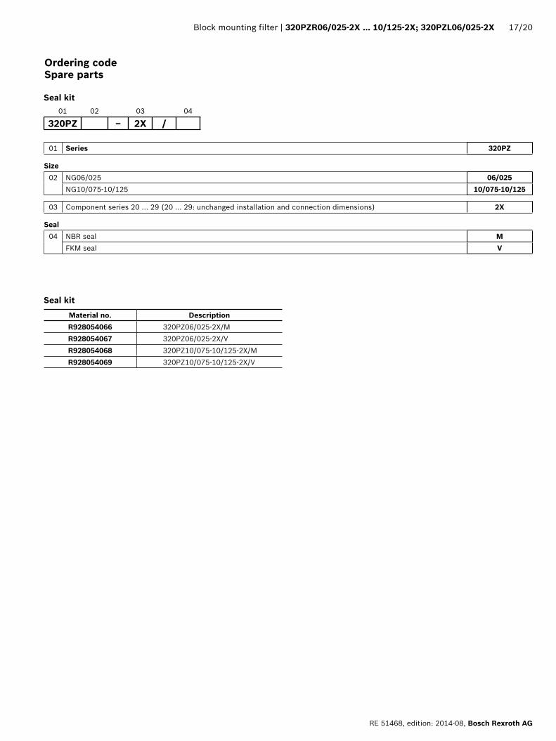
Ordering code Spare parts
Material no. DescriptionR928054066 320PZ06/025-2X/MR928054067 320PZ06/025-2X/VR928054068 320PZ10/075-10/125-2X/MR928054069 320PZ10/075-10/125-2X/V
01 Series 320PZ
Size02 NG06/025 06/025
NG10/075-10/125 10/075-10/125
03 Component series 20 … 29 (20 … 29: unchanged installation and connection dimensions) 2X
Seal04 NBR seal M
FKM seal V
01 02 03 04
320PZ – 2X /
Seal kit
Seal kit
18/20 320PZR06/025-2X … 10/125-2X; 320PZL06/025-2X | Block mounting filter
Bosch Rexroth AG, RE 51468, edition: 2014-08
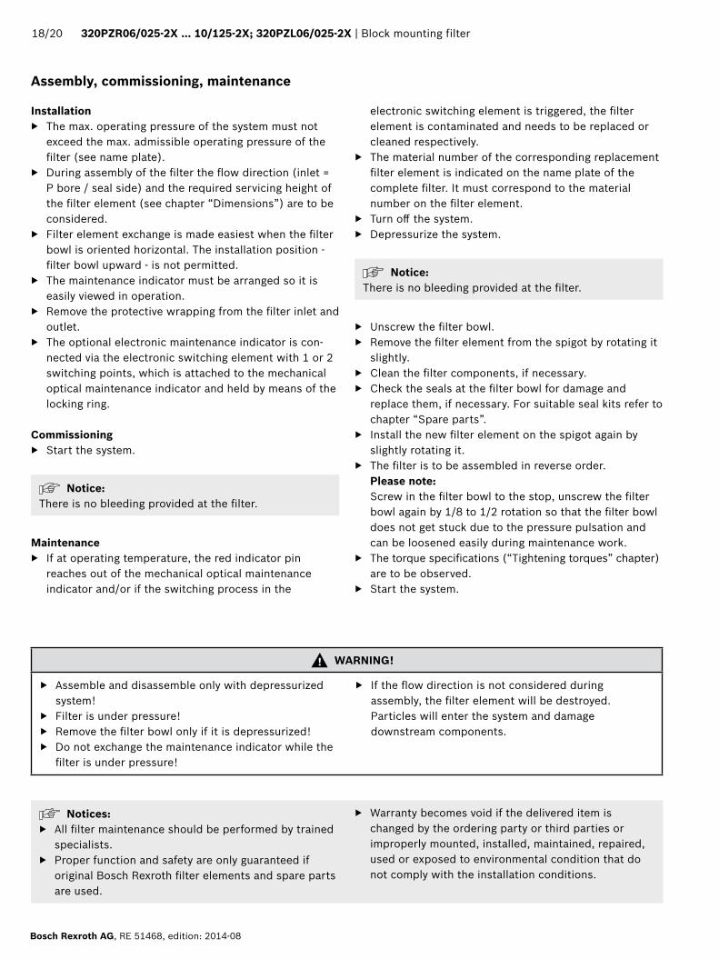
Assembly, commissioning, maintenance
Installation ▶ The max. operating pressure of the system must not
exceed the max. admissible operating pressure of the filter (see name plate).
▶ During assembly of the filter the flow direction (inlet = P bore / seal side) and the required servicing height of the filter element (see chapter “Dimensions”) are to be considered.
▶ Filter element exchange is made easiest when the filter bowl is oriented horizontal. The installation position - filter bowl upward - is not permitted.
▶ The maintenance indicator must be arranged so it is easily viewed in operation.
▶ Remove the protective wrapping from the filter inlet and outlet.
▶ The optional electronic maintenance indicator is con-nected via the electronic switching element with 1 or 2 switching points, which is attached to the mechanical optical maintenance indicator and held by means of the locking ring.
Commissioning ▶ Start the system.
Notice: There is no bleeding provided at the filter.
Maintenance ▶ If at operating temperature, the red indicator pin
reaches out of the mechanical optical maintenance indicator and/or if the switching process in the
electronic switching element is triggered, the filter element is contaminated and needs to be replaced or cleaned respectively.
▶ The material number of the corresponding replacement filter element is indicated on the name plate of the complete filter. It must correspond to the material number on the filter element.
▶ Turn off the system. ▶ Depressurize the system.
Notice: There is no bleeding provided at the filter.
▶ Unscrew the filter bowl. ▶ Remove the filter element from the spigot by rotating it
slightly. ▶ Clean the filter components, if necessary. ▶ Check the seals at the filter bowl for damage and
replace them, if necessary. For suitable seal kits refer to chapter “Spare parts”.
▶ Install the new filter element on the spigot again by slightly rotating it.
▶ The filter is to be assembled in reverse order. Please note: Screw in the filter bowl to the stop, unscrew the filter bowl again by 1/8 to 1/2 rotation so that the filter bowl does not get stuck due to the pressure pulsation and can be loosened easily during maintenance work.
▶ The torque specifications (“Tightening torques” chapter) are to be observed.
▶ Start the system.
Notices: ▶ All filter maintenance should be performed by trained
specialists. ▶ Proper function and safety are only guaranteed if
original Bosch Rexroth filter elements and spare parts are used.
▶ Warranty becomes void if the delivered item is changed by the ordering party or third parties or improperly mounted, installed, maintained, repaired, used or exposed to environmental condition that do not comply with the installation conditions.
WARNING!
▶ Assemble and disassemble only with depressurized system!
▶ Filter is under pressure! ▶ Remove the filter bowl only if it is depressurized! ▶ Do not exchange the maintenance indicator while the
filter is under pressure!
▶ If the flow direction is not considered during assembly, the filter element will be destroyed. Particles will enter the system and damage downstream components.

Block mounting filter | 320PZR06/025-2X … 10/125-2X; 320PZL06/025-2X 19/20
RE 51468, edition: 2014-08, Bosch Rexroth AG
Series 320PZR/PZL06/025 320PZR10/075 320PZR10/125
Filter bowl Screw in the filter bowl to the stop, unscrew the filter bowl again by 1/8 to 1/2 rotation
Mechanical optical maintenance indicator Max. 50 Nm [37lb-ft]Cubic connector screw switching element EN-175301-803 M3/0.5 Nm [0.4 lb-ft]
Tightening torque (dimensions in mm [in])
Classification according to the Pressure Equipment DirectiveThe block mounting filter for hydraulic applications according to 51468 are pressure holding equipment according to article 1, section 2.1.4 of the Pressure Equipment Directive 97/23/EC (PED). However, based on the exception in article 1, section 3.6 of the PEG, hydraulic
filters are exempt from the PED if they are not classified higher than category I (guideline 1/19).The fluids from the chapter “Compatibility with approved pressure fluids” were considered for the classification.They do not receive a CE mark.
zone suitabilityGas 1 2Dust 21 22
Use in potentially explosive areas according to directive 94/9/EC (ATEX)The block mounting filter according to 51468 are not equipment or components in the sense of directive 94/9/EC and are not provided with a CE mark. It has been proven with the ignition risk analysis that these block mounting filters do not have own ignition sources acc. to DIN EN 13463-1:2009.
According to DIN EN 60079-11:2012, electronic maintenance indicators with a switching point:WE-1SP-M12x1 R928028409 WE-1SP-EN175301-803 R928036318
are simple, electronic operating equipment that do not have an own voltage source. This simple, electronic operating equipment may - according to DIN EN 60079-14:2012 - in intrinsically safe electric circuits (Ex ib) be used in systems without marking and certification.The block mounting filters and the electronic maintenance indicators described here can be used for the following explosive areas:
Complete filter with mech./opt. Maintenance indicatorUse /assignment Gas 2G Dust 2D
Assignment Ex II 2G c IIC TX Ex II 2D c IIC TXConductivity of the medium pS/m min 300
Dust accumulation max ‒ 0.5 mm
electronic switching element in the intrinsically safe electric circuitUse /assignment Gas 2G Dust 2D
Assignment Ex II 2G Ex ib IIB T4 Gb Ex II 2D Ex ib IIIC T100°C Dbperm. intrinsically safe electric circuits Ex ib IIC, Ex ic IIC Ex ib IIIC
Technical data Values only for intrinsically safe electric circuitSwitching voltage Ui max 150 V AC/DC Switching current Ii max 1.0 A Switching power Pi max 1.3 W T4 Tmax 40 °C 750 mW Tmax 40 °C
max 1.0 W T4 Tmax 80 °C 550 mW Tmax 100 °CSurface temperature 1) max ‒ 100 °Cinner capacity Ci negligibleinner inductivity Li negligibleDust accumulation max ‒ 0.02 in1) The temperature depends on the temperature of the medium in the filter and must not exceed the value specified here.
Directives and standardization
���
���
20/20 320PZR06/025-2X … 10/125-2X; 320PZL06/025-2X | Block mounting filter
Bosch Rexroth AG, RE 51468, edition: 2014-08
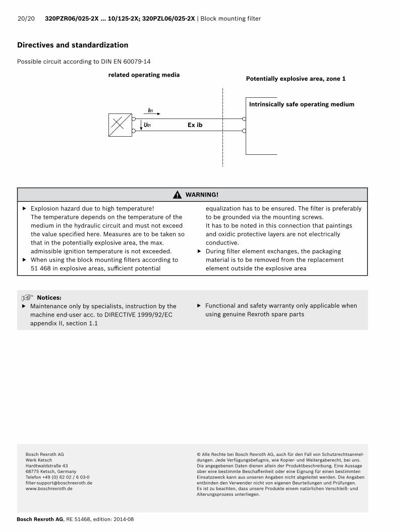
Possible circuit according to DIN EN 60079-14
related operating media Potentially explosive area, zone 1
Intrinsically safe operating medium
Ex ib
Directives and standardization
Notices: ▶ Maintenance only by specialists, instruction by the
machine end-user acc. to DIRECTIVE 1999/92/EC appendix II, section 1.1
▶ Functional and safety warranty only applicable when using genuine Rexroth spare parts
WARNING!
▶ Explosion hazard due to high temperature! The temperature depends on the temperature of the medium in the hydraulic circuit and must not exceed the value specified here. Measures are to be taken so that in the potentially explosive area, the max. admissible ignition temperature is not exceeded.
▶ When using the block mounting filters according to 51 468 in explosive areas, sufficient potential
equalization has to be ensured. The filter is preferably to be grounded via the mounting screws. It has to be noted in this connection that paintings and oxidic protective layers are not electrically conductive.
▶ During filter element exchanges, the packaging material is to be removed from the replacement element outside the explosive area
Bosch Rexroth AGWerk KetschHardtwaldstraße 4368775 Ketsch, GermanyTelefon +49 (0) 62 02 / 6 [email protected]
© Alle Rechte bei Bosch Rexroth AG, auch für den Fall von Schutzrechtsanmel-dungen. Jede Verfügungsbefugnis, wie Kopier- und Weitergaberecht, bei uns.Die angegebenen Daten dienen allein der Produktbeschreibung. Eine Aussage über eine bestimmte Beschaffenheit oder eine Eignung für einen bestimmten Einsatzzweck kann aus unseren Angaben nicht abgeleitet werden. Die Angaben entbinden den Verwender nicht von eigenen Beurteilungen und Prüfungen. Es ist zu beachten, dass unsere Produkte einem natürlichen Verschleiß- und Alterungsprozess unterliegen.
Related Documents