Washington University in St. Louis Washington University in St. Louis Washington University Open Scholarship Washington University Open Scholarship Mechanical Engineering Design Project Class Mechanical Engineering & Materials Science Fall 12-10-2017 Blind-Automation Device Blind-Automation Device Melinda Lai Washington University in St. Louis Dalton Nonweiler Washington University in St. Louis Haley Nichols Washington University in St. Louis Follow this and additional works at: https://openscholarship.wustl.edu/mems411 Part of the Mechanical Engineering Commons Recommended Citation Recommended Citation Lai, Melinda; Nonweiler, Dalton; and Nichols, Haley, "Blind-Automation Device" (2017). Mechanical Engineering Design Project Class. 74. https://openscholarship.wustl.edu/mems411/74 This Final Report is brought to you for free and open access by the Mechanical Engineering & Materials Science at Washington University Open Scholarship. It has been accepted for inclusion in Mechanical Engineering Design Project Class by an authorized administrator of Washington University Open Scholarship. For more information, please contact [email protected].

Welcome message from author
This document is posted to help you gain knowledge. Please leave a comment to let me know what you think about it! Share it to your friends and learn new things together.
Transcript
Washington University in St. Louis Washington University in St. Louis
Washington University Open Scholarship Washington University Open Scholarship
Mechanical Engineering Design Project Class Mechanical Engineering & Materials Science
Fall 12-10-2017
Blind-Automation Device Blind-Automation Device
Melinda Lai Washington University in St. Louis
Dalton Nonweiler Washington University in St. Louis
Haley Nichols Washington University in St. Louis
Follow this and additional works at: https://openscholarship.wustl.edu/mems411
Part of the Mechanical Engineering Commons
Recommended Citation Recommended Citation Lai, Melinda; Nonweiler, Dalton; and Nichols, Haley, "Blind-Automation Device" (2017). Mechanical Engineering Design Project Class. 74. https://openscholarship.wustl.edu/mems411/74
This Final Report is brought to you for free and open access by the Mechanical Engineering & Materials Science at Washington University Open Scholarship. It has been accepted for inclusion in Mechanical Engineering Design Project Class by an authorized administrator of Washington University Open Scholarship. For more information, please contact [email protected].
MEMS 411: Senior Design Project
Blind-Automation Device
Melinda Lai
Haley Nichols
Dalton Nonweiler
Executive Summary
Our team set out to design and build a device to automatically move window covers. A
series of interviews were conducted to determine project scope, customer needs, and target
specifications. Based on the input of four interviewees, we designed six concepts for an
inexpensive product that tilt twist-style blinds in response to ambient light levels and a time-
based schedule. The concepts were scored and a single proof-of-concept prototype was created
using a combination of 3D printing, basic analog circuitry, and an Arduino microcontroller. After
parts were sourced and assembly began, we conducted an engineering analysis on the included
blind stick and wall mounting system to ensure safe and consistent operation. Finally, through a
week-long testing period, it was found that the prototype met or exceeded all performance goals
and is a viable candidate for future development.
Blind-Automation Device Introduction and Background Information
Page 1 of 48
TABLE OF CONTENTS List of FigureS .......................................................................................................................................... 4
List of Tables ............................................................................................................................................ 4
1 Introduction and Background Information............................................................................................ 5
1.1 Initial Project Description ............................................................................................................. 5
1.2 Existing Products .......................................................................................................................... 5
1.3 Relevant Patents ............................................................................................................................ 7
1.4 Codes & Standards ........................................................................................................................ 7
1.5 Project Scope ................................................................................................................................ 7
1.6 Project Planning ............................................................................................................................ 8
1.7 Realistic Constraints ..................................................................................................................... 8
1.7.1 Functional ............................................................................................................................. 8
1.7.2 Safety .................................................................................................................................... 8
1.7.3 Quality ................................................................................................................................... 8
1.7.4 Manufacturing ....................................................................................................................... 8
1.7.5 Timing ................................................................................................................................... 8
1.7.6 Economic .............................................................................................................................. 9
1.7.7 Ergonomic ............................................................................................................................. 9
1.7.8 Ecological ............................................................................................................................. 9
1.7.9 Aesthetic ............................................................................................................................... 9
1.7.10 Life Cycle .............................................................................................................................. 9
1.7.11 Legal ..................................................................................................................................... 9
1.8 Revised Project Description .......................................................................................................... 9
2 Customer Needs & Product Specifications ......................................................................................... 10
2.1 Customer Interviews ................................................................................................................... 10
2.2 Interpreted Customer Needs........................................................................................................ 10
2.3 Target Specifications................................................................................................................... 11
3 Concept Generation ............................................................................................................................ 12
3.1 Functional Decomposition .......................................................................................................... 12
3.2 Morphological Chart ................................................................................................................... 13
3.3 Concept #1 – “Knobby” .............................................................................................................. 13
3.4 Concept #2 – “Internet Blinds” ................................................................................................... 14
3.5 Concept #3 – “Solar Blinds” ....................................................................................................... 14
Blind-Automation Device Introduction and Background Information
Page 2 of 48
3.6 Concept #4 – “Blindostat” .......................................................................................................... 15
3.7 Concept #5 – “High Tech” .......................................................................................................... 16
3.8 Concept #6 – “low Tech” ............................................................................................................ 17
4 Concept Selection ............................................................................................................................... 17
4.1 Concept Scoring Matrix .............................................................................................................. 17
4.2 Explanation of Winning Concept Scores .................................................................................... 18
4.3 Explanation of Second-Place Concept Scores ............................................................................ 19
4.4 Explanation of Third-Place Concept Scores ............................................................................... 20
4.5 Summary of Evaluation Results .................................................................................................. 20
5 Embodiment & Fabrication plan ......................................................................................................... 21
5.1 Isometric Drawing with Bill of Materials ................................................................................... 21
5.2 Exploded View ............................................................................................................................ 22
5.3 Additional Views ........................................................................................................................ 23
6 Engineering Analysis .......................................................................................................................... 25
6.1 Engineering Analysis Results ..................................................................................................... 25
6.1.1 Motivation ........................................................................................................................... 25
6.1.2 Summary Statement of the Analysis ................................................................................... 26
6.1.3 Methodology ....................................................................................................................... 26
6.1.4 Results ................................................................................................................................. 27
6.1.5 Significance ......................................................................................................................... 27
6.2 Product Risk Assessment ............................................................................................................ 28
6.2.1 Risk Identification ............................................................................................................... 28
6.2.2 Risk Heat Map .................................................................................................................... 29
6.2.3 Risk Prioritization ............................................................................................................... 29
7 Design Documentation ........................................................................................................................ 30
7.1 Performance Goals ...................................................................................................................... 30
7.2 Working Prototype Demonstration ............................................................................................. 30
7.2.1 Performance Evaluation ...................................................................................................... 30
7.2.2 Working Prototype – Video Link ........................................................................................ 30
7.2.3 Additional Photos ................................................................................................................ 30
8 Discussion ........................................................................................................................................... 34
8.1 Design for Manufacturing – Part Redesign for Injection Molding ............................................. 34
8.1.1 Draft Analysis Results ........................................................................................................ 34
Blind-Automation Device Introduction and Background Information
Page 3 of 48
8.1.2 Explanation of Design Changes .......................................................................................... 34
8.2 Design for Usability – Effect of Impairments on Usability ........................................................ 35
8.2.1 Vision .................................................................................................................................. 35
8.2.2 Hearing ................................................................................................................................ 35
8.2.3 Physical ............................................................................................................................... 35
8.2.4 Language ............................................................................................................................. 35
8.2 Overall Experience ...................................................................................................................... 35
8.2.1 Does your final project result align with the initial project description? ............................ 35
8.2.2 Was the project more or less difficult than you had expected? ........................................... 35
8.2.3 In what ways do you wish your final prototype would have performed better? ................. 36
8.2.4 Was your group missing any critical information when you evaluated concepts? ............. 36
8.2.5 Were there additional engineering analyses that could have helped guide your design? ... 36
8.2.6 How did you identify your most relevant codes and standards and how they influence
revision of the design? ........................................................................................................................ 36
8.2.7 What ethical considerations (from the Engineering Ethics and Design for Environment
seminar) are relevant to your device? How could these considerations be addressed? ...................... 36
8.2.8 On which part(s) of the design process should your group have spent more time? Which
parts required less time? ...................................................................................................................... 36
8.2.9 Was there a task on your Gantt chart that was much harder than expected? Were there any
that were much easier? ........................................................................................................................ 36
8.2.10 Was there a component of your prototype that was significantly easier or harder to
make/assemble than you expected? .................................................................................................... 37
8.2.11 If your budget were increased to 10x its original amount, would your approach have
changed? If so, in what specific ways? ............................................................................................... 37
8.2.12 If you were able to take the course again with the same project and group, what would you
have done differently the second time around? ................................................................................... 37
8.2.13 Were your team member’s skills complementary? ............................................................. 37
8.2.14 Was any needed skill missing from the group? .................................................................. 37
8.2.15 Has the project enhanced your design skills? ..................................................................... 37
8.2.16 Would you now feel more comfortable accepting a design project assignment at a job?... 37
8.2.17 Are there projects you would attempt now that you would not have attempted before? .... 37
9 Appendix A - Parts List ...................................................................................................................... 38
10 Appendix B - CAD Models ............................................................................................................ 39
11 Appendix c – Arduino Code ........................................................................................................... 40
12 Annotated Bibliography .................................................................................................................. 48
Blind-Automation Device Introduction and Background Information
Page 4 of 48
LIST OF FIGURES
Figure 1: Somfy Ondeis wireless rain and sun sensor .................................................................................. 5 Figure 2: Thermo Sunis wireless sun sensor (indoor) ................................................................................... 6 Figure 3: Hunter Douglas PowerView Motorization .................................................................................... 6 Figure 4: Gantt Chart .................................................................................................................................... 8 Figure 5: Function tree ................................................................................................................................ 12 Figure 6: Morphological Chart ................................................................................................................... 13 Figure 7: Concept 1 – “Knobby” ................................................................................................................ 14 Figure 8: Concept 2 – “Internet Blinds” ..................................................................................................... 14 Figure 9: Concept 3 – “Solar Blinds” ......................................................................................................... 15 Figure 10: Concept 4 - "Blindostat" ............................................................................................................ 16 Figure 11: Concept 5- “High Tech” ............................................................................................................ 16 Figure 13: Concept 6 – “Low Tech” ........................................................................................................... 17 Figure 14: Concept Scoring Matrix ............................................................................................................ 17 Figure 15: Winning Concept – “Knobby” .................................................................................................. 18 Figure 16: Second place concept - "Blindostat"..................................................................................... 19 Figure 17: Third place concept - "Solar Blinds" ................................................................................... 20 Figure 18: Isometric CAD drawing ............................................................................................................ 21 Figure 19: CAD Exploded View ................................................................................................................. 22 Figure 20: Front view with bill of materials ............................................................................................... 23 Figure 21: Top view .................................................................................................................................... 24 Figure 22: Isometric drawing including device lid ..................................................................................... 25 Figure 23: SOLIDWORKS Motion results: von Mises stress on blind wand hook ................................... 26 Figure 24: SOLIDWORKS Motion methodology: fixed face and torque applied ..................................... 27 Figure 25: Risk Assessment Heat Map ....................................................................................................... 29 Figure 26: Photo of prototype: Isometric view ........................................................................................... 30 Figure 27: Photo of prototype: front view .................................................................................................. 31 Figure 28: Photo of prototype: front isometric view ................................................................................... 32 Figure 29: Photo of prototype: side view .................................................................................................... 32 Figure 30: Photo of prototype: internal view .............................................................................................. 33 Figure 31: Project enclosure before drafting ............................................................................................... 34 Figure 32: Post-drafting evaluation of the project enclosure ...................................................................... 34 Figure 33: List of Parts ............................................................................................................................... 38 Figure 34: CAD Model; Project Enclosure ................................................................................................. 39 Figure 35: CAD Model; Project Enclosure Lid .......................................................................................... 40 Figure 36: Arduino code for prototype ....................................................................................................... 41
LIST OF TABLES
Table 1: Interpreted Needs .......................................................................................................................... 11
Table 2: Target Specifications .................................................................................................................... 11
Blind-Automation Device Introduction and Background Information
Page 5 of 48
1 INTRODUCTION AND BACKGROUND INFORMATION
1.1 INITIAL PROJECT DESCRIPTION
People forget to open their blinds in the morning and close them at night. Opening the
blinds in the morning can be a cost-effective way of heating a room during the winter months,
while closing them during the day can save energy during the summer. An affordable, easy to
install automated blind actuator based on ambient light level measurement will eliminate these
problems.
1.2 EXISTING PRODUCTS
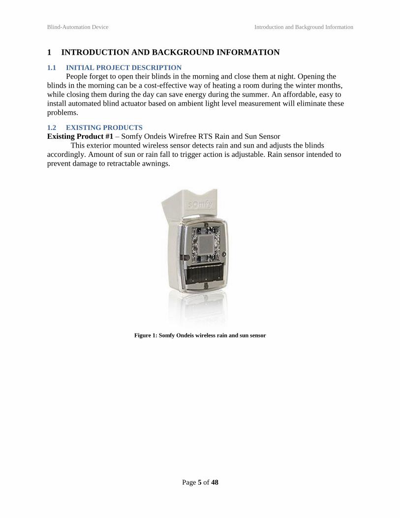
Existing Product #1 – Somfy Ondeis Wirefree RTS Rain and Sun Sensor
This exterior mounted wireless sensor detects rain and sun and adjusts the blinds
accordingly. Amount of sun or rain fall to trigger action is adjustable. Rain sensor intended to
prevent damage to retractable awnings.
Figure 1: Somfy Ondeis wireless rain and sun sensor
Blind-Automation Device Introduction and Background Information
Page 6 of 48
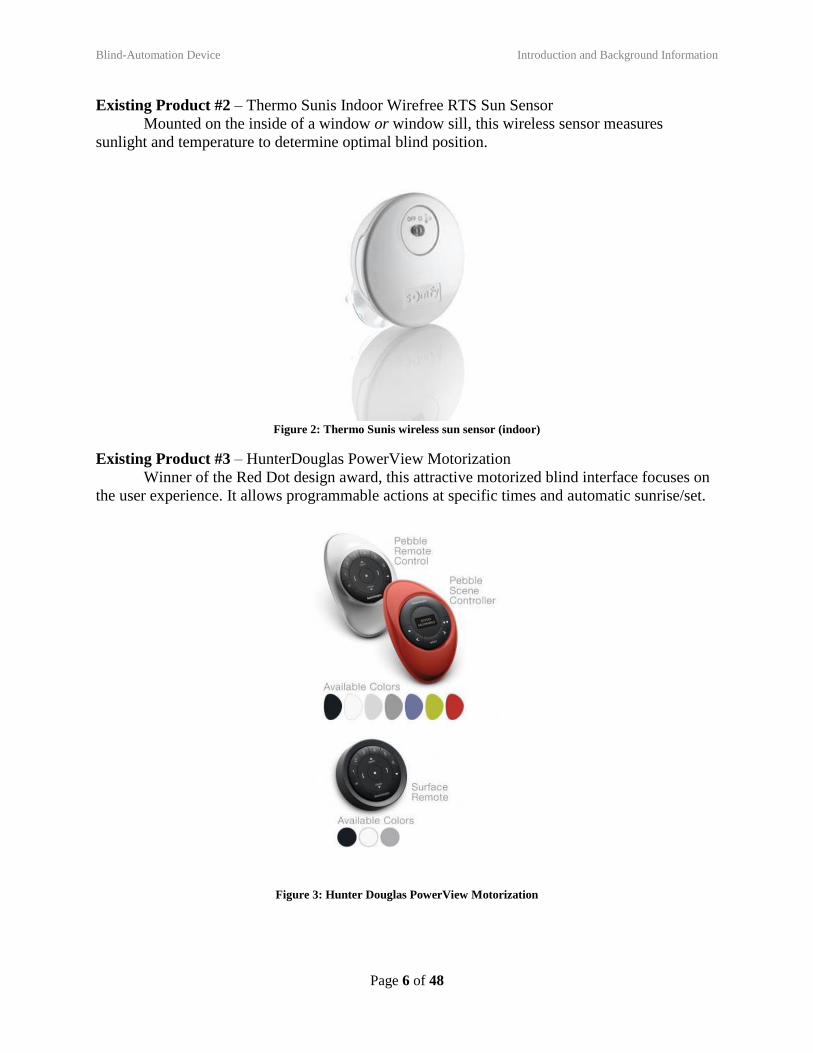
Existing Product #2 – Thermo Sunis Indoor Wirefree RTS Sun Sensor
Mounted on the inside of a window or window sill, this wireless sensor measures
sunlight and temperature to determine optimal blind position.
Figure 2: Thermo Sunis wireless sun sensor (indoor)
Existing Product #3 – HunterDouglas PowerView Motorization
Winner of the Red Dot design award, this attractive motorized blind interface focuses on
the user experience. It allows programmable actions at specific times and automatic sunrise/set.
Figure 3: Hunter Douglas PowerView Motorization
Blind-Automation Device Introduction and Background Information
Page 7 of 48
1.3 RELEVANT PATENTS
Patent #1 – US5760558A
Solar powered, wireless, retro-fit-able. Intended for venetian blinds. This patent depicts a
possible mechanism to point us in the right direction for initial concept generation. It’s useful to
first think of what kind(s) of shades/blinds we want this device to be compatible for.
https://patents.google.com/patent/US5760558A/en
Patent #2 –
An interesting but wordy claim related to modeling the effects of sunlight on a buildings
HVAC system for use alongside an automated blind system. The data they collect and analyze is
interesting and could be a good starting point for our design.
https://patents.google.com/patent/US20130063065A1/en?q=automatic&q=blinds&sort=new&pa
ge=1
1.4 CODES & STANDARDS
The codes and standards that have the possibility applying to our project are outlined in
ANSI WCMA A100. These codes are primarily concerned with child safety, primarily
restrictions on cord properties. These requirements influenced our decision in choosing how we
decided which blinds to focus our project on.
1.5 PROJECT SCOPE
This project is intended to be a safe, easy, and inexpensive addition to window covers to
maintain consistent indoor lighting by automatically adjusting blinds in response to ambient light
levels.
Our target customers are homeowners/renters and business owners concerned about
employee productivity and wellness. This product will allow homeowners, business owners, and
building tenants to increase occupant productivity. Bright sunlight can cause glare, making
employees uncomfortable and reducing their productivity, along with their health. The product
will automatically adjust window blinds to maintain a comfortable interior lighting level,
promoting productivity and the bottom line. The product can also reduce building energy
consumption in the summer by reducing the amount of solar heat gain through the windows.
The main goals of our project are to ensure that we have a safe device that works with
current blinds without modification, maintains comfortable interior light level, requires low
maintenance and is quick to install. Our blind automation device will not be temperature
dependent, move the blinds up and down or be solar powered. We are assuming that potential
customers will already own twist style blinds and will agree with our definition of the acceptable
light level.
Blind-Automation Device Introduction and Background Information
Page 8 of 48
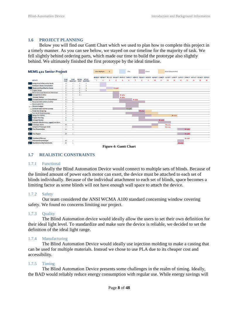
1.6 PROJECT PLANNING
Below you will find our Gantt Chart which we used to plan how to complete this project in
a timely manner. As you can see below, we stayed on our timeline for the majority of task. We
fell slightly behind ordering parts, which made our time to build the prototype also slightly
behind. We ultimately finished the first prototype by the ideal timeline.
Figure 4: Gantt Chart
1.7 REALISTIC CONSTRAINTS
1.7.1 Functional
Ideally the Blind Automation Device would connect to multiple sets of blinds. Because of
the limited amount of power each motor can exert, the device must be attached to each set of
blinds individually. Because of the individual attachment to each set of blinds, space becomes a
limiting factor as some blinds will not have enough wall space to attach the device.
1.7.2 Safety
Our team considered the ANSI WCMA A100 standard concerning window covering
safety. We found no concerns limiting our project.
1.7.3 Quality
The Blind Automation device would ideally allow the users to set their own definition for
their ideal light level. To standardize and make sure the device is reliable, we decided to set the
definition of the ideal light range.
1.7.4 Manufacturing
The Blind Automation Device would ideally use injection molding to make a casting that
can be used for multiple materials. Instead we chose to use PLA due to its cheaper cost and
accessibility.
1.7.5 Timing
The Blind Automation Device presents some challenges in the realm of timing. Ideally,
the BAD would reliably reduce energy consumption with regular use. While energy savings will
Blind-Automation Device Introduction and Background Information
Page 9 of 48
probably still occur, our team did not have enough time to verify and refine the schedule to
ensure energy savings. Even without ensuring that energy savings exist, the device will require
several iterations to achieve a clean and compact version ready for market. This process could
take several months. If a better user interface is desired, significant time will be invested to add a
screen or wireless application. We produced only the first of these prototypes. While we are far
from a manufacture-ready product, our design is scalable and, with some changes, would be easy
and inexpensive to manufacture.
1.7.6 Economic
Because we wanted to create a prototype on a budget and also pass on a reasonable
market price, we were very conscious of manufacturing costs. From our market analysis, we
wanted to remain inexpensive. We chose to 3-D print our casing; ideally, we would want to use
injection molded plastic for the case, but this would be unrealistically costly for a single
prototype. An LED screen would provide a friendlier user interface, but would be more costly to
implement. We were also unable to implement a wireless network of multiple linked blind
controls because that would be too costly.
1.7.7 Ergonomic
Our team decided that the ultimate ergonomic interface is a smartphone app. We decided
to pursue a simple manual interface using knobs, switches, and LEDs instead to limit price and
development time.
1.7.8 Ecological
The first prototype of the device is not limited by ecological constraints.
1.7.9 Aesthetic
Ideally, we would want to place the light sensor on the ceiling above the blinds, as this is
the location with minimal shadow and interference from people and other moving objects. This
would involve lots of cords and would be ugly, therefore we decided to place the light sensor
next to the window, by the box, in a position that is not as visually intrusive.
To make a less costly product, we could do away with the 3-D printed case we have
designed; we would simply need anything to cover the electronics. However, for aesthetic
reasons, we designed a custom printed case to contain the components of our device.
1.7.10 Life Cycle
The only moving parts in this device are the stepper motor and the universal joints. Both
have extremely long life cycles, thus analysis was overlooked until later stages of manufacturing.
1.7.11 Legal
Extensive patent and legal research yielded no considerations that held back our design.
1.8 REVISED PROJECT DESCRIPTION
The Blind-Automation Device or “BAD” is a safe, easy, and inexpensive retrofit to window
cover systems that maintains consistent indoor lighting. BAD functions by automatically
adjusting blinds in response to ambient light levels.
Blind-Automation Device Customer Needs & Product Specifications
Page 10 of 48
2 CUSTOMER NEEDS & PRODUCT SPECIFICATIONS
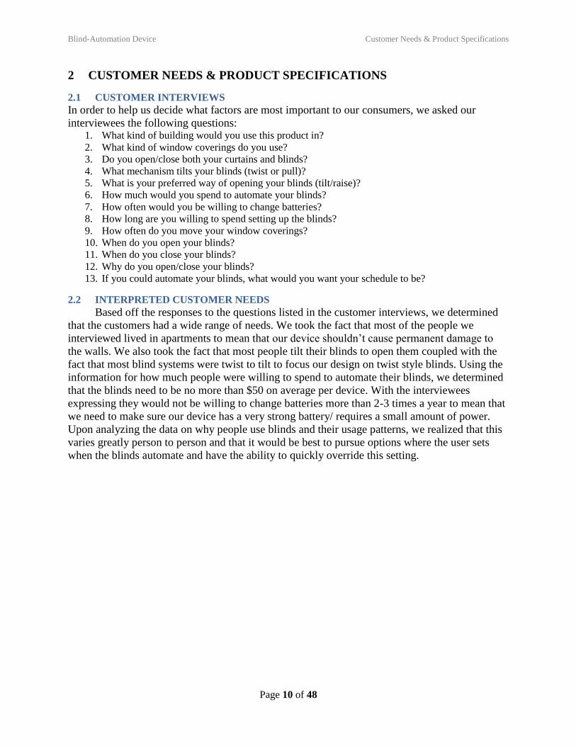
2.1 CUSTOMER INTERVIEWS
In order to help us decide what factors are most important to our consumers, we asked our
interviewees the following questions: 1. What kind of building would you use this product in?
2. What kind of window coverings do you use?
3. Do you open/close both your curtains and blinds?
4. What mechanism tilts your blinds (twist or pull)?
5. What is your preferred way of opening your blinds (tilt/raise)?
6. How much would you spend to automate your blinds?
7. How often would you be willing to change batteries?
8. How long are you willing to spend setting up the blinds?
9. How often do you move your window coverings?
10. When do you open your blinds?
11. When do you close your blinds?
12. Why do you open/close your blinds?
13. If you could automate your blinds, what would you want your schedule to be?
2.2 INTERPRETED CUSTOMER NEEDS
Based off the responses to the questions listed in the customer interviews, we determined
that the customers had a wide range of needs. We took the fact that most of the people we
interviewed lived in apartments to mean that our device shouldn’t cause permanent damage to
the walls. We also took the fact that most people tilt their blinds to open them coupled with the
fact that most blind systems were twist to tilt to focus our design on twist style blinds. Using the
information for how much people were willing to spend to automate their blinds, we determined
that the blinds need to be no more than $50 on average per device. With the interviewees
expressing they would not be willing to change batteries more than 2-3 times a year to mean that
we need to make sure our device has a very strong battery/ requires a small amount of power.
Upon analyzing the data on why people use blinds and their usage patterns, we realized that this
varies greatly person to person and that it would be best to pursue options where the user sets
when the blinds automate and have the ability to quickly override this setting.
Blind-Automation Device Customer Needs & Product Specifications
Page 11 of 48
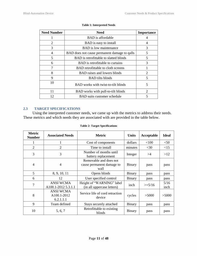
Table 1: Interpreted Needs
Need Number Need Importance
1 BAD is affordable 4
2 BAD is easy to install 4
3 BAD is low maintenance 3
4 BAD does not cause permanent damage to qalls 5
5 BAD is retrofittable to slatted blinds 5
6 BAD is retrofittable to curtains 3
7 BAD retrofittable to cloth screens 1
8 BAD raises and lowers blinds 2
9 BAD tilts blinds 5
10
BAD works with twist-to-tilt blinds 5
11 BAD works with pull-to-tilt blinds 2
12 BAD suits customer schedule 5
2.3 TARGET SPECIFICATIONS
Using the interpreted customer needs, we came up with the metrics to address their needs.
These metrics and which needs they are associated with are provided in the table below.
Table 2: Target Specifications
Metric
Number Associated Needs Metric Units Acceptable Ideal
1 1 Cost of components dollars <100 <50
2 2 Time to install minutes <30 <15
3 3 Number of months until
battery replacement Integer >4 >12
4 4
Removable and does not
cause permanent damage to
wall
Binary pass pass
5 8, 9, 10, 11 Opens blinds Binary pass pass
6 12 User specified control Binary pass pass
7 ANSI WCMA
A100.1-2012 5.3.1.1
Height of “WARNING” label
(in all uppercase letters) inch >=5/16
5/16
inch
8
ANSI WCMA
A100.1-2012
6.2.1.1.1
Service life of cord retraction
device cycles >5000 >5000
9 Team defined Stays securely attached Binary pass pass
10 5, 6, 7 Retrofittable to existing
blinds Binary pass pass
Blind-Automation Device Concept Generation
Page 12 of 48
3 CONCEPT GENERATION
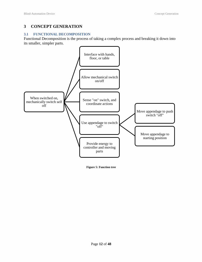
3.1 FUNCTIONAL DECOMPOSITION
Functional Decomposition is the process of taking a complex process and breaking it down into
its smaller, simpler parts.
Figure 5: Function tree
When switched on, mechanically switch self
off
Interface with hands, floor, or table
Allow mechanical switch on/off
Sense "on" switch, and coordinate actions
Use appendage to switch "off"
Move appendage to push switch "off"
Move appendage to starting position
Provide energy to controller and moving
parts
Blind-Automation Device Concept Generation
Page 13 of 48
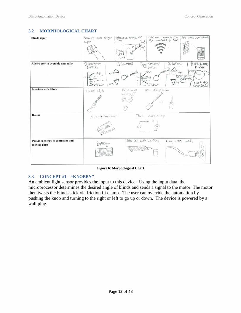
3.2 MORPHOLOGICAL CHART
Figure 6: Morphological Chart
3.3 CONCEPT #1 – “KNOBBY”
An ambient light sensor provides the input to this device. Using the input data, the
microprocessor determines the desired angle of blinds and sends a signal to the motor. The motor
then twists the blinds stick via friction fit clamp. The user can override the automation by
pushing the knob and turning to the right or left to go up or down. The device is powered by a
wall plug.
Blind-Automation Device Concept Generation
Page 14 of 48
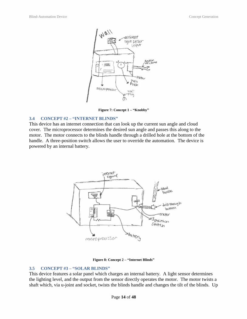
Figure 7: Concept 1 – “Knobby”
3.4 CONCEPT #2 – “INTERNET BLINDS”
This device has an internet connection that can look up the current sun angle and cloud
cover. The microprocessor determines the desired sun angle and passes this along to the
motor. The motor connects to the blinds handle through a drilled hole at the bottom of the
handle. A three-position switch allows the user to override the automation. The device is
powered by an internal battery.
Figure 8: Concept 2 – “Internet Blinds”
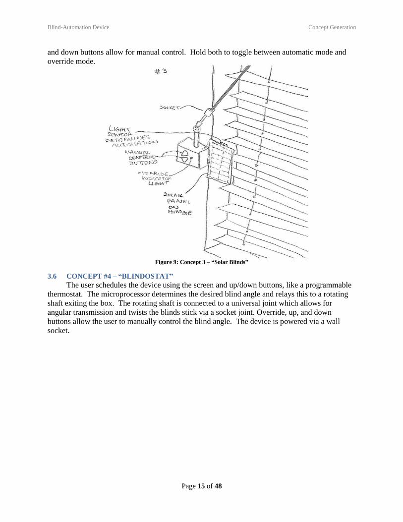
3.5 CONCEPT #3 – “SOLAR BLINDS”
This device features a solar panel which charges an internal battery. A light sensor determines
the lighting level, and the output from the sensor directly operates the motor. The motor twists a
shaft which, via u-joint and socket, twists the blinds handle and changes the tilt of the blinds. Up
Blind-Automation Device Concept Generation
Page 15 of 48
and down buttons allow for manual control. Hold both to toggle between automatic mode and
override mode.
Figure 9: Concept 3 – “Solar Blinds”
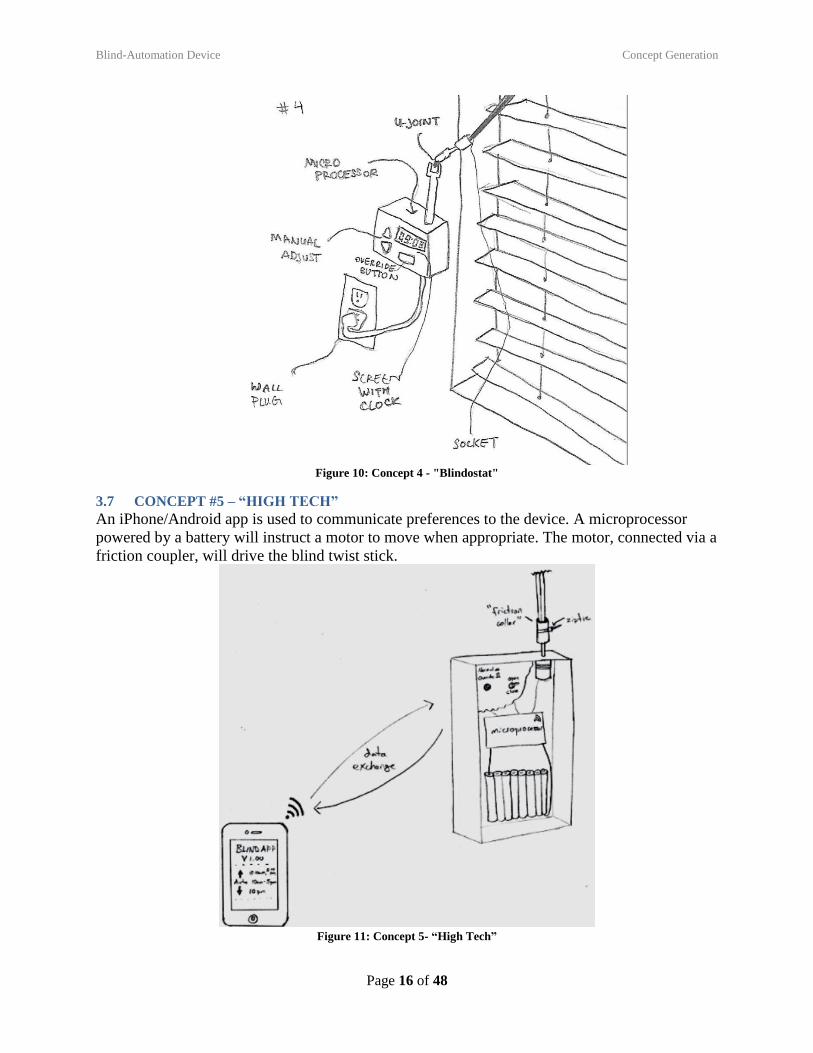
3.6 CONCEPT #4 – “BLINDOSTAT”
The user schedules the device using the screen and up/down buttons, like a programmable
thermostat. The microprocessor determines the desired blind angle and relays this to a rotating
shaft exiting the box. The rotating shaft is connected to a universal joint which allows for
angular transmission and twists the blinds stick via a socket joint. Override, up, and down
buttons allow the user to manually control the blind angle. The device is powered via a wall
socket.
Blind-Automation Device Concept Generation
Page 16 of 48
Figure 10: Concept 4 - "Blindostat"
3.7 CONCEPT #5 – “HIGH TECH”
An iPhone/Android app is used to communicate preferences to the device. A microprocessor
powered by a battery will instruct a motor to move when appropriate. The motor, connected via a
friction coupler, will drive the blind twist stick.
Figure 11: Concept 5- “High Tech”
Blind-Automation Device Concept Selection
Page 17 of 48
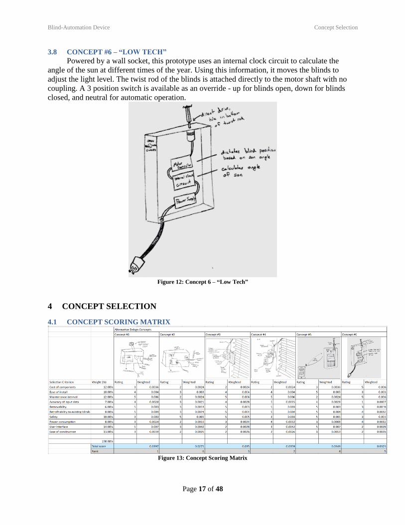
3.8 CONCEPT #6 – “LOW TECH”
Powered by a wall socket, this prototype uses an internal clock circuit to calculate the
angle of the sun at different times of the year. Using this information, it moves the blinds to
adjust the light level. The twist rod of the blinds is attached directly to the motor shaft with no
coupling. A 3 position switch is available as an override - up for blinds open, down for blinds
closed, and neutral for automatic operation.
Figure 12: Concept 6 – “Low Tech”
4 CONCEPT SELECTION
4.1 CONCEPT SCORING MATRIX
Figure 13: Concept Scoring Matrix
Blind-Automation Device Concept Selection
Page 18 of 48
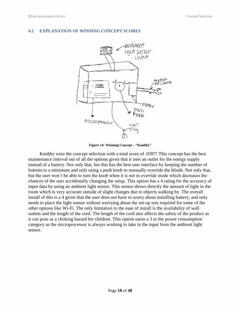
4.2 EXPLANATION OF WINNING CONCEPT SCORES
Figure 14: Winning Concept – “Knobby”
Knobby wins the concept selection with a total score of .0397! This concept has the best
maintenance interval out of all the options given that it uses an outlet for the energy supply
instead of a battery. Not only that, but this has the best user interface by keeping the number of
buttons to a minimum and only using a push knob to manually override the blinds. Not only that,
but the user won’t be able to turn the knob when it is not in override mode which decreases the
chances of the user accidentally changing the setup. This option has a 4 rating for the accuracy of
input data by using an ambient light sensor. This sensor shows directly the amount of light in the
room which is very accurate outside of slight changes due to objects walking by. The overall
install of this is a 4 given that the user does not have to worry about installing battery, and only
needs to place the light sensor without worrying about the set-up sets required for some of the
other options like Wi-Fi. The only limitation to the ease of install is the availability of wall
outlets and the length of the cord. The length of the cord also affects the safety of the product as
it can pose as a choking hazard for children. This option earns a 3 in the power consumption
category as the microprocessor is always working to take in the input from the ambient light
sensor.
Blind-Automation Device Concept Selection
Page 19 of 48
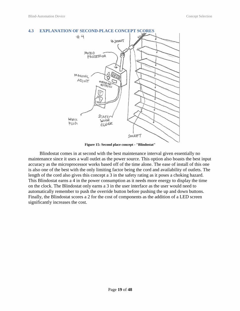
4.3 EXPLANATION OF SECOND-PLACE CONCEPT SCORES
Figure 15: Second place concept - "Blindostat"
Blindostat comes in at second with the best maintenance interval given essentially no
maintenance since it uses a wall outlet as the power source. This option also boasts the best input
accuracy as the microprocessor works based off of the time alone. The ease of install of this one
is also one of the best with the only limiting factor being the cord and availability of outlets. The
length of the cord also gives this concept a 3 in the safety rating as it poses a choking hazard.
This Blindostat earns a 4 in the power consumption as it needs more energy to display the time
on the clock. The Blindostat only earns a 3 in the user interface as the user would need to
automatically remember to push the override button before pushing the up and down buttons.
Finally, the Blindostat scores a 2 for the cost of components as the addition of a LED screen
significantly increases the cost.
Blind-Automation Device Concept Selection
Page 20 of 48
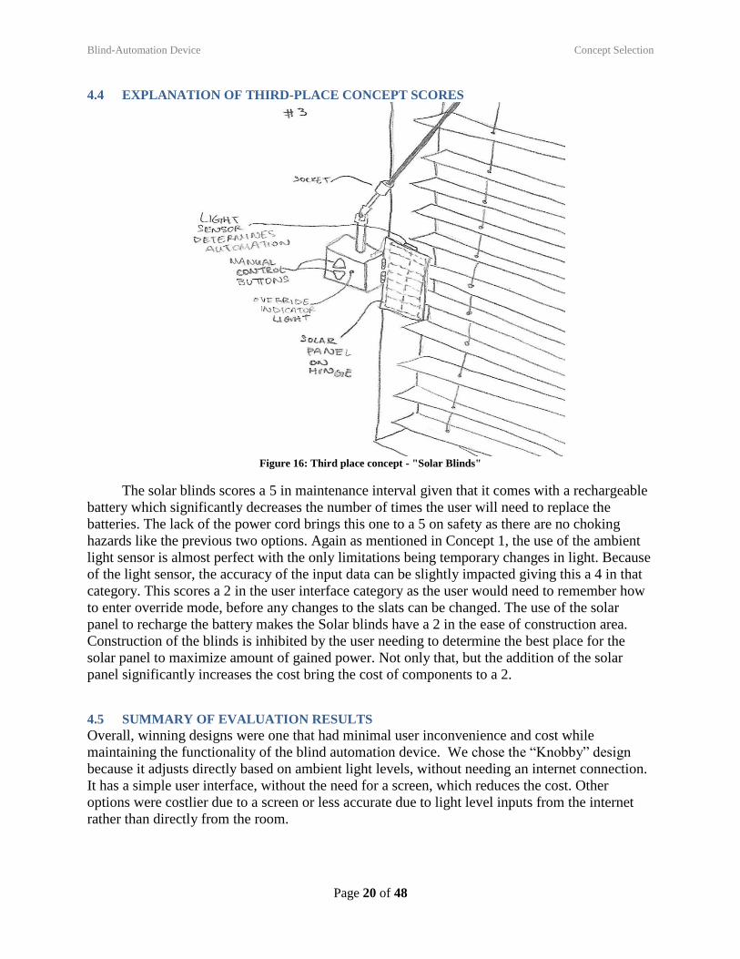
4.4 EXPLANATION OF THIRD-PLACE CONCEPT SCORES
Figure 16: Third place concept - "Solar Blinds"
The solar blinds scores a 5 in maintenance interval given that it comes with a rechargeable
battery which significantly decreases the number of times the user will need to replace the
batteries. The lack of the power cord brings this one to a 5 on safety as there are no choking
hazards like the previous two options. Again as mentioned in Concept 1, the use of the ambient
light sensor is almost perfect with the only limitations being temporary changes in light. Because
of the light sensor, the accuracy of the input data can be slightly impacted giving this a 4 in that
category. This scores a 2 in the user interface category as the user would need to remember how
to enter override mode, before any changes to the slats can be changed. The use of the solar
panel to recharge the battery makes the Solar blinds have a 2 in the ease of construction area.
Construction of the blinds is inhibited by the user needing to determine the best place for the
solar panel to maximize amount of gained power. Not only that, but the addition of the solar
panel significantly increases the cost bring the cost of components to a 2.
4.5 SUMMARY OF EVALUATION RESULTS
Overall, winning designs were one that had minimal user inconvenience and cost while
maintaining the functionality of the blind automation device. We chose the “Knobby” design
because it adjusts directly based on ambient light levels, without needing an internet connection.
It has a simple user interface, without the need for a screen, which reduces the cost. Other
options were costlier due to a screen or less accurate due to light level inputs from the internet
rather than directly from the room.
Blind-Automation Device Embodiment & Fabrication plan
Page 21 of 48
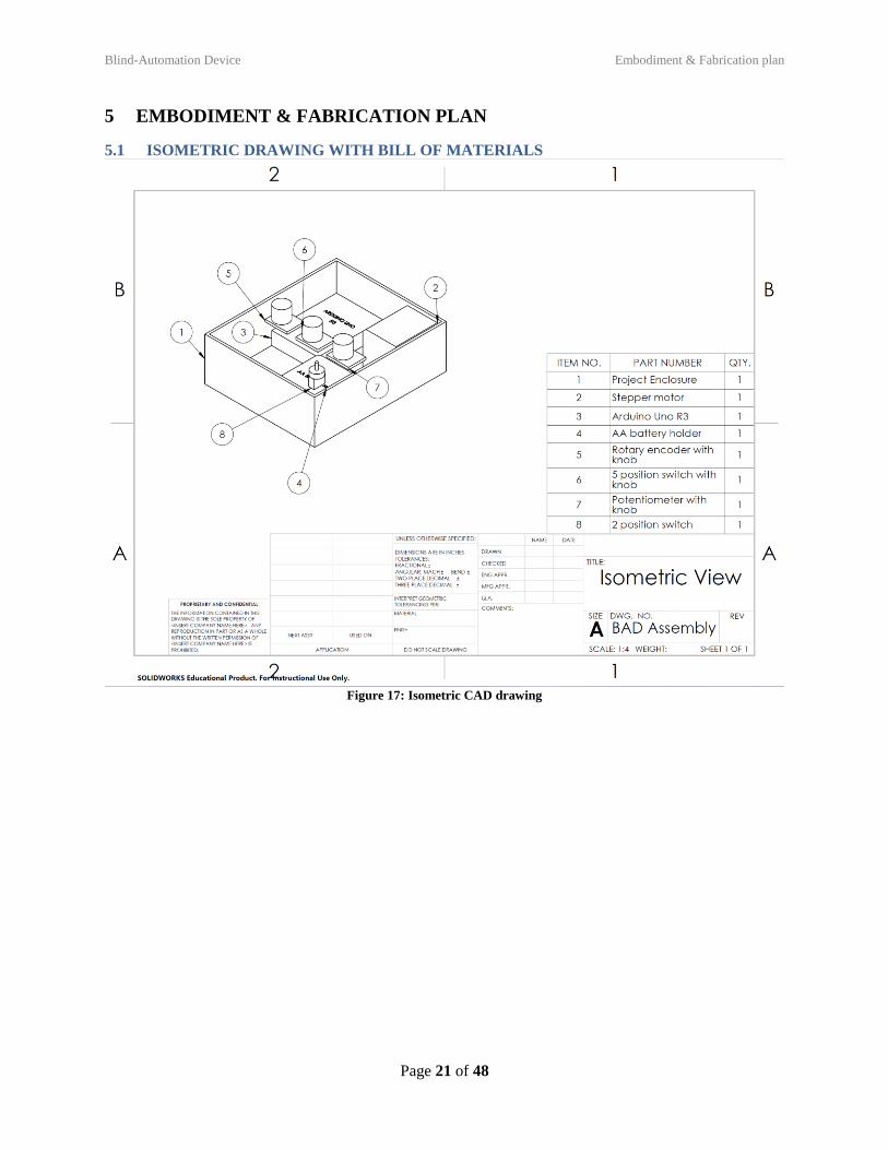
5 EMBODIMENT & FABRICATION PLAN
5.1 ISOMETRIC DRAWING WITH BILL OF MATERIALS
Figure 17: Isometric CAD drawing
Blind-Automation Device Embodiment & Fabrication plan
Page 22 of 48
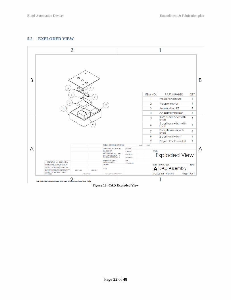
5.2 EXPLODED VIEW
Figure 18: CAD Exploded View
Blind-Automation Device Embodiment & Fabrication plan
Page 23 of 48
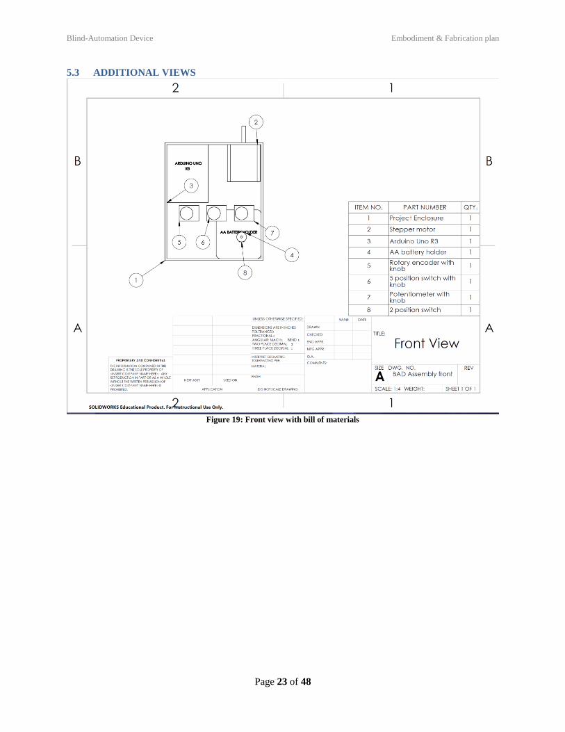
5.3 ADDITIONAL VIEWS
Figure 19: Front view with bill of materials
Blind-Automation Device Embodiment & Fabrication plan
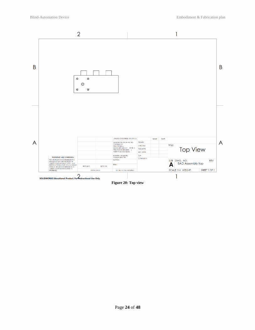
Page 24 of 48
Figure 20: Top view
Blind-Automation Device Engineering Analysis
Page 25 of 48
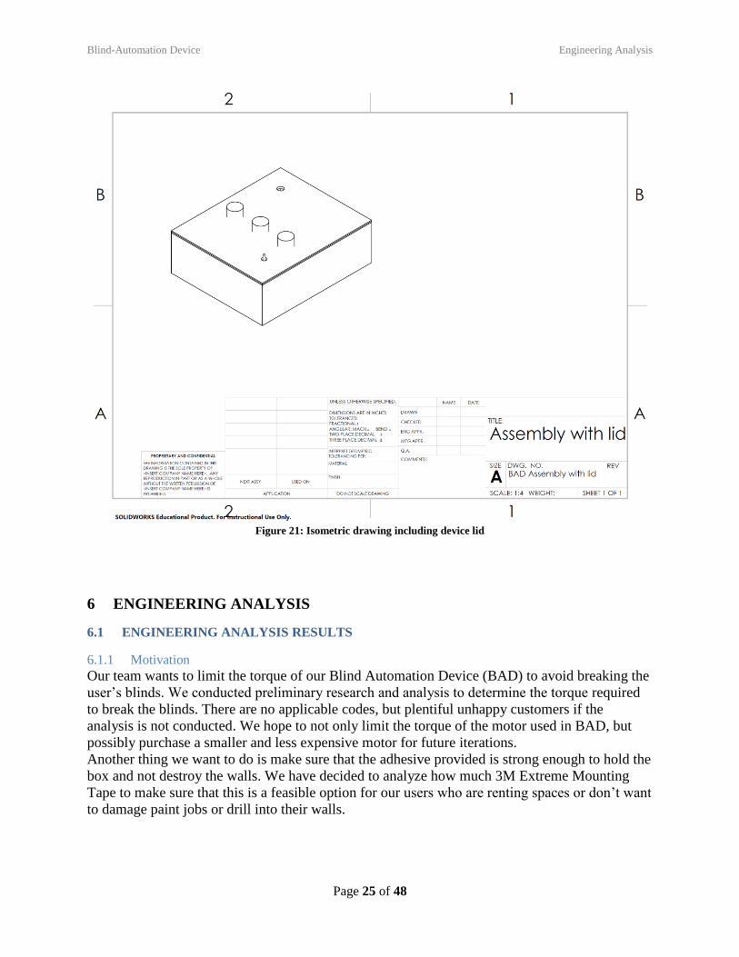
Figure 21: Isometric drawing including device lid
6 ENGINEERING ANALYSIS
6.1 ENGINEERING ANALYSIS RESULTS
6.1.1 Motivation
Our team wants to limit the torque of our Blind Automation Device (BAD) to avoid breaking the
user’s blinds. We conducted preliminary research and analysis to determine the torque required
to break the blinds. There are no applicable codes, but plentiful unhappy customers if the
analysis is not conducted. We hope to not only limit the torque of the motor used in BAD, but
possibly purchase a smaller and less expensive motor for future iterations.
Another thing we want to do is make sure that the adhesive provided is strong enough to hold the
box and not destroy the walls. We have decided to analyze how much 3M Extreme Mounting
Tape to make sure that this is a feasible option for our users who are renting spaces or don’t want
to damage paint jobs or drill into their walls.
Blind-Automation Device Engineering Analysis
Page 26 of 48
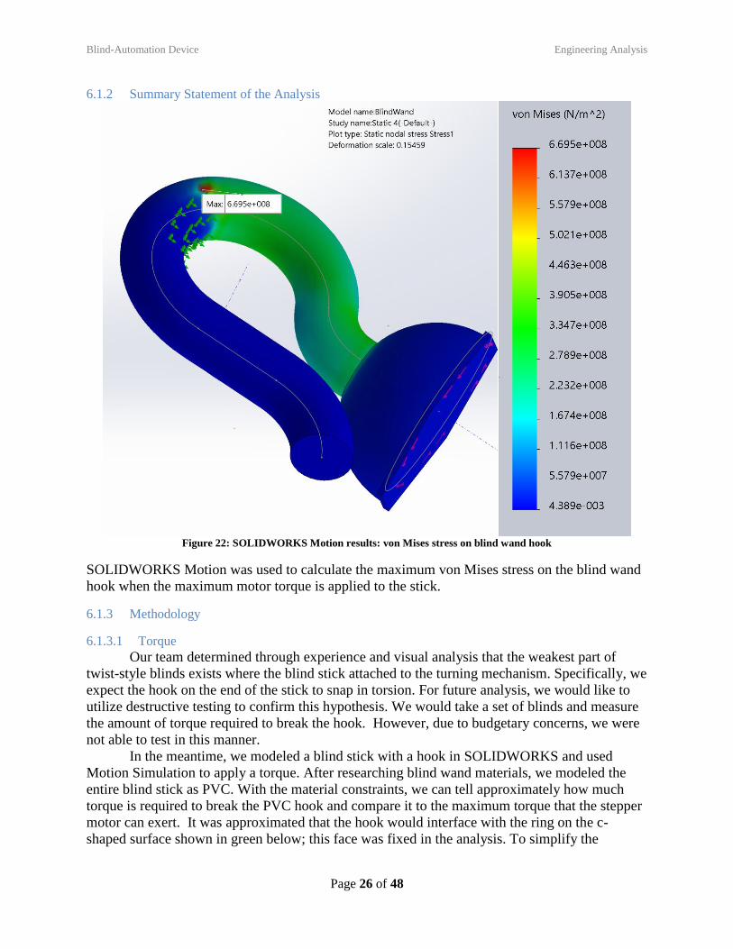
6.1.2 Summary Statement of the Analysis
Figure 22: SOLIDWORKS Motion results: von Mises stress on blind wand hook
SOLIDWORKS Motion was used to calculate the maximum von Mises stress on the blind wand
hook when the maximum motor torque is applied to the stick.
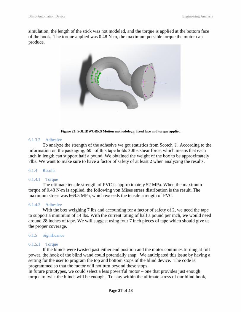
6.1.3 Methodology
6.1.3.1 Torque
Our team determined through experience and visual analysis that the weakest part of
twist-style blinds exists where the blind stick attached to the turning mechanism. Specifically, we
expect the hook on the end of the stick to snap in torsion. For future analysis, we would like to
utilize destructive testing to confirm this hypothesis. We would take a set of blinds and measure
the amount of torque required to break the hook. However, due to budgetary concerns, we were
not able to test in this manner.
In the meantime, we modeled a blind stick with a hook in SOLIDWORKS and used
Motion Simulation to apply a torque. After researching blind wand materials, we modeled the
entire blind stick as PVC. With the material constraints, we can tell approximately how much
torque is required to break the PVC hook and compare it to the maximum torque that the stepper
motor can exert. It was approximated that the hook would interface with the ring on the c-
shaped surface shown in green below; this face was fixed in the analysis. To simplify the
Blind-Automation Device Engineering Analysis
Page 27 of 48
simulation, the length of the stick was not modeled, and the torque is applied at the bottom face
of the hook. The torque applied was 0.48 N-m, the maximum possible torque the motor can
produce.
Figure 23: SOLIDWORKS Motion methodology: fixed face and torque applied
6.1.3.2 Adhesive
To analyze the strength of the adhesive we got statistics from Scotch ®. According to the
information on the packaging, 60” of this tape holds 30lbs shear force, which means that each
inch in length can support half a pound. We obtained the weight of the box to be approximately
7lbs. We want to make sure to have a factor of safety of at least 2 when analyzing the results.
6.1.4 Results
6.1.4.1 Torque
The ultimate tensile strength of PVC is approximately 52 MPa. When the maximum
torque of 0.48 N-m is applied, the following von Mises stress distribution is the result. The
maximum stress was 669.5 MPa, which exceeds the tensile strength of PVC.
6.1.4.2 Adhesive
With the box weighing 7 lbs and accounting for a factor of safety of 2, we need the tape
to support a minimum of 14 lbs. With the current rating of half a pound per inch, we would need
around 28 inches of tape. We will suggest using four 7 inch pieces of tape which should give us
the proper coverage.
6.1.5 Significance
6.1.5.1 Torque
If the blinds were twisted past either end position and the motor continues turning at full
power, the hook of the blind wand could potentially snap. We anticipated this issue by having a
setting for the user to program the top and bottom stops of the blind device. The code is
programmed so that the motor will not turn beyond these stops.
In future prototypes, we could select a less powerful motor – one that provides just enough
torque to twist the blinds will be enough. To stay within the ultimate stress of our blind hook,
Blind-Automation Device Engineering Analysis
Page 28 of 48
we would want to select a motor with a maximum torque of 0.15 Nm. Alternatively, we could
reinforce our hook with electrical tape. However, we felt that with our current software checks,
we did not need to change our current design concept.
6.1.5.2 Adhesive
Considering the current amount of tape that would be required to ensure that it can safely
support the weight of the box, we might consider other taping options. This amount of tape will
essentially cover the back of the box, which seems excessive. With this in mind, we also think
that this number is excessive because the tape itself has a built in factor of safety. We tested this
with 10 inches of tape and it held the device overnight.
6.2 PRODUCT RISK ASSESSMENT
6.2.1 Risk Identification
1) Adhesive failure
a. Description: If the adhesive fails, the box can fall off the wall. We are currently managing
this by using strong adhesives.
b. Impact – 2 If the adhesive fails, then the most that’ll happen is that the user will need to
reattach device to wall.
c. Likelihood – 3 This is likely if the adhesive weakens over time, or if the user does not
properly install
2) Motor keeps spinning and breaks blinds
a. Description: Malfunction of hardware can lead to the motor constantly spinning. Currently
stopping and testing the code to minimize the possibility of code making this error.
b. Impact – 4 The device will essentially not function as intended if this happens
c. Likelihood –2 We think this is unlikely, because we testing the code and error-proofed it.
3) Entanglement
a. Description: User clothing/hair could get caught in u-joint.
b. Impact –1 This will personally effect the user, not the function of the device.
c. Likelihood –1 This is unlikely given that the user will not be near the device during most of
the device lifespan
4) Water Damage
a. Description: The box is not weatherproof. Water from a leaky window could enter box and
destroy components
b. Impact –3 This could destroy the internal components which could effect how the device
works
c. Likelihood –1 We think this isn’t likely that a user will put this on a leaky window
5) Fire
a. Description: Excess heat from motor could cause fire.
b. Impact –5 This would be serious, because the device will no longer function and the safety of
the user will be impacted
c. Likelihood –1 We used safe circuitry to minimize the chances of this happening.
6) Lacerations
a. Description: User could injure self on box edges.
b. Impact –1 The user could potentially cut themselves, but the device will still work normally
c. Likelihood –3 This is average likelihood given that the box does not have rounded corner
Blind-Automation Device Engineering Analysis
Page 29 of 48
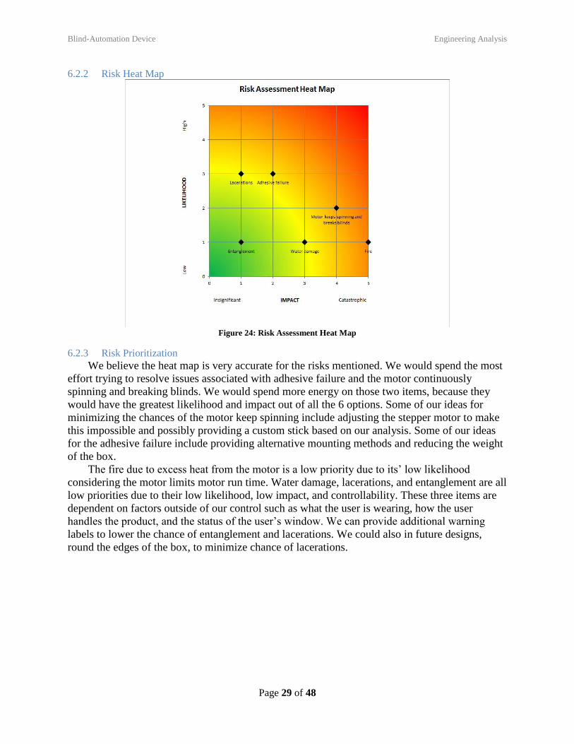
6.2.2 Risk Heat Map
Figure 24: Risk Assessment Heat Map
6.2.3 Risk Prioritization
We believe the heat map is very accurate for the risks mentioned. We would spend the most
effort trying to resolve issues associated with adhesive failure and the motor continuously
spinning and breaking blinds. We would spend more energy on those two items, because they
would have the greatest likelihood and impact out of all the 6 options. Some of our ideas for
minimizing the chances of the motor keep spinning include adjusting the stepper motor to make
this impossible and possibly providing a custom stick based on our analysis. Some of our ideas
for the adhesive failure include providing alternative mounting methods and reducing the weight
of the box.
The fire due to excess heat from the motor is a low priority due to its’ low likelihood
considering the motor limits motor run time. Water damage, lacerations, and entanglement are all
low priorities due to their low likelihood, low impact, and controllability. These three items are
dependent on factors outside of our control such as what the user is wearing, how the user
handles the product, and the status of the user’s window. We can provide additional warning
labels to lower the chance of entanglement and lacerations. We could also in future designs,
round the edges of the box, to minimize chance of lacerations.
Blind-Automation Device Design Documentation
Page 30 of 48
7 DESIGN DOCUMENTATION
7.1 PERFORMANCE GOALS
1. BAD will take less than 15 minutes to install
2. BAD knob positions worked correctly
3. BAD will change slat angle in response to complete darkness and bright light
4. BAD will automatically adjust blinds to appropriate angle within 1 minute of light level
change
5. BAD will automatically keep blinds closed during user defined night time
7.2 WORKING PROTOTYPE DEMONSTRATION
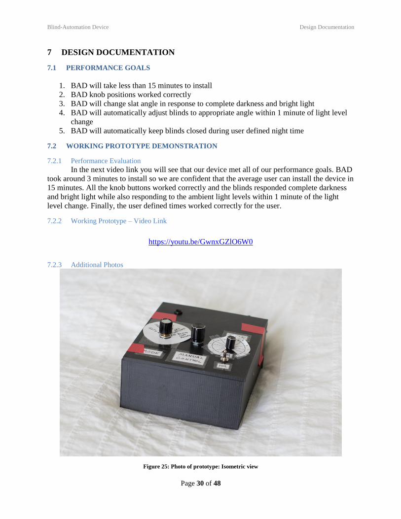
7.2.1 Performance Evaluation
In the next video link you will see that our device met all of our performance goals. BAD
took around 3 minutes to install so we are confident that the average user can install the device in
15 minutes. All the knob buttons worked correctly and the blinds responded complete darkness
and bright light while also responding to the ambient light levels within 1 minute of the light
level change. Finally, the user defined times worked correctly for the user.
7.2.2 Working Prototype – Video Link
https://youtu.be/GwnxGZlO6W0
7.2.3 Additional Photos
Figure 25: Photo of prototype: Isometric view
Blind-Automation Device Design Documentation
Page 31 of 48
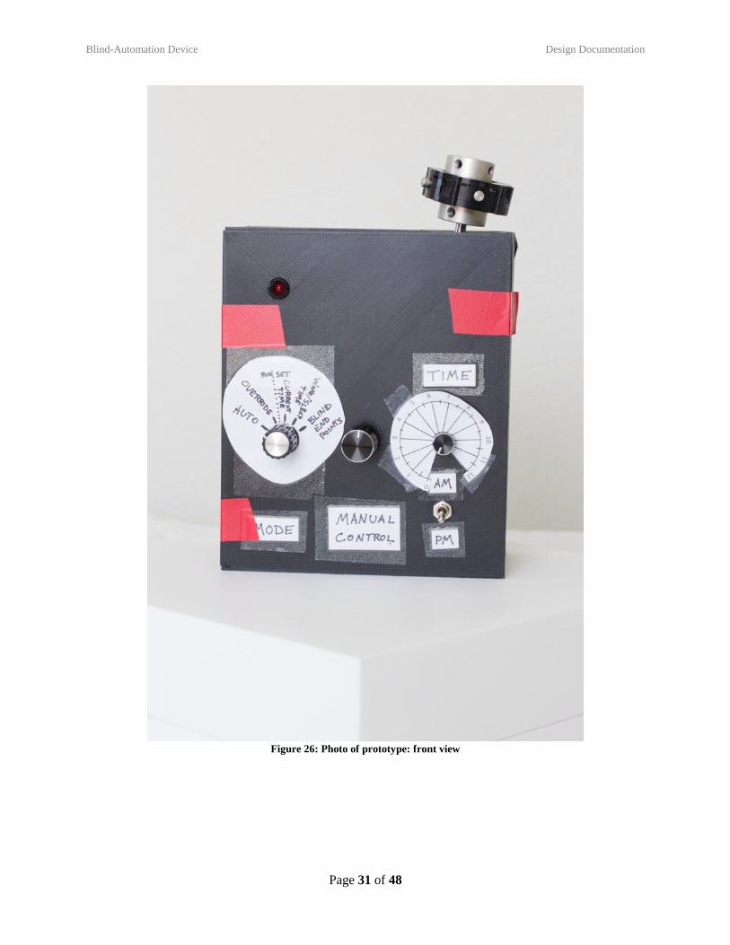
Figure 26: Photo of prototype: front view
Blind-Automation Device Design Documentation
Page 32 of 48
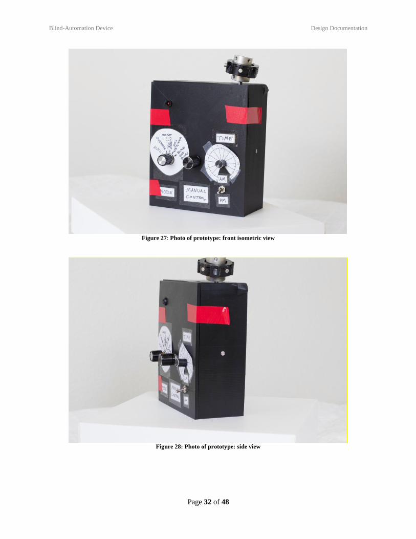
Figure 27: Photo of prototype: front isometric view
Figure 28: Photo of prototype: side view
Blind-Automation Device Design Documentation
Page 33 of 48
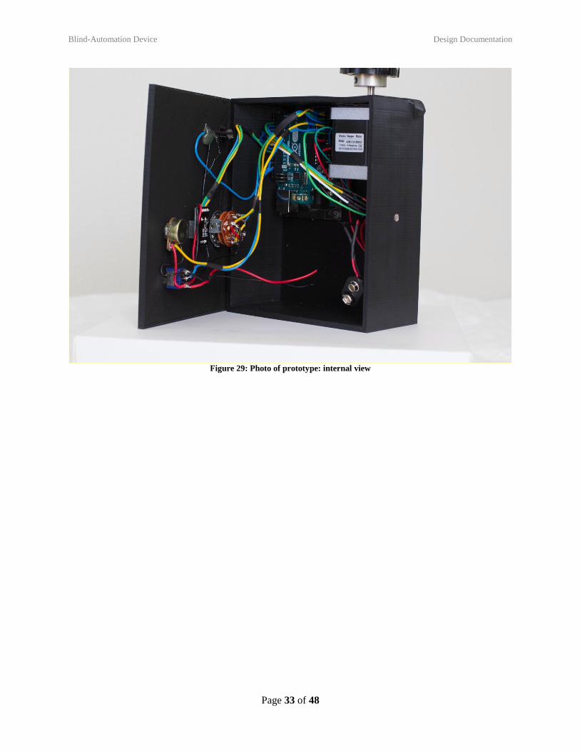
Figure 29: Photo of prototype: internal view
Blind-Automation Device Discussion
Page 34 of 48
8 DISCUSSION
8.1 DESIGN FOR MANUFACTURING – PART REDESIGN FOR INJECTION MOLDING
8.1.1 Draft Analysis Results
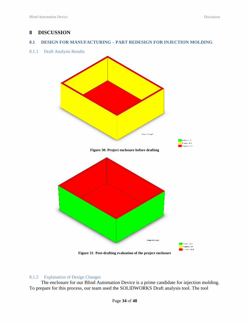
Figure 30: Project enclosure before drafting
Figure 31: Post-drafting evaluation of the project enclosure
8.1.2 Explanation of Design Changes
The enclosure for our Blind Automation Device is a prime candidate for injection molding.
To prepare for this process, our team used the SOLIDWORKS Draft analysis tool. The tool
Blind-Automation Device Discussion
Page 35 of 48
found that 8 faces required drafting before injection molding is feasible. After applying several
different draft angles, it was found that a -2-degree draft angle on all vertical surfaces produced a
part that can be injection molded. See the Fig. 20 and Fig. 21 below for a side by side
comparison of the test results before and after our changes.
8.2 DESIGN FOR USABILITY – EFFECT OF IMPAIRMENTS ON USABILITY
8.2.1 Vision
A vision impairment, such as red-green color blindness or presbyopia, may
influence the usability of our device because much of our user interface is visually based. Labels
on the knobs and switches are visual, and the LED is a visual indicator as well. Some of the
labels, especially the ticks for the time knob and the labels for the five-position switch may be
difficult to read with presbyopia. Red-green color blindness should not impair the usability of
our device. We could improve usability for people with a vision impairment by providing
physical raised ticks that can be felt with the hand, thicker lines, larger font, and knobs that are
farther apart. We could also provide an auditory indicator to supplement the LED.
8.2.2 Hearing
A hearing impairment such as Presbycutia, would not affect the usability of our
device. However, it may affect safety. A user without a hearing impairment may be able to hear
an unusual noise or hum coming from the device if something were going wrong with the
device. A user with a hearing impairment may not have this benefit.
8.2.3 Physical
A physical impairment such as arthritis, muscle weakness, or limb immobilization, may
influence the usability of our device because the knobs and switches to control the device are
relatively small and require a moderate amount of finger space. Individuals with physical
impairments may have trouble gripping the small knobs and making the minute adjustments
sometimes necessary to operate the device. We could improve the device by making knobs
larger and easier to grip.
8.2.4 Language
A language impairment (i.e. speaking little or no English, in this case) may influence the
usability of your device, as all our instructions and the position labels on the 5-position switch
are in English. We could improve our product by providing instructions and labels in pictograph
or in other common languages.
8.2 OVERALL EXPERIENCE
8.2.1 Does your final project result align with the initial project description?
Our final project aligned with the initial project description. Our goal was to maintain a
comfortable ambient light level inside a room by adjusting the angle of Venetian blinds through
a retrofit. We were able to do so.
8.2.2 Was the project more or less difficult than you had expected?
Some aspects of the project were more difficult, and others were less difficult than we
had expected. The coding was much more difficult than anticipated. We spent most of the time
coding, which was challenging because none of us were very familiar with Arduino. Once we
Blind-Automation Device Discussion
Page 36 of 48
got the code to work and everything wired correctly, the mechanical components of this project
were not too challenging.
8.2.3 In what ways do you wish your final prototype would have performed better?
It would be nice to have a better user interface. The current setup with three knobs and a
switch is a little bit confusing. Ideally, we would have a screen and fewer knobs, but this was
not feasible with our budget. We also burn through batteries quickly because the stepper motor is
always powered. Ideally, our device would have some sort of “sleep mode” to minimize power
consumption.
8.2.4 Was your group missing any critical information when you evaluated concepts?
We did not know that the stepper motor would need power even when it was not moving.
If we had known this when we evaluated our options, we may have chosen a different motor or
designed a way to power it only when needed.
8.2.5 Were there additional engineering analyses that could have helped guide your design?
An analysis of power consumption could have helped us with battery selection.
8.2.6 How did you identify your most relevant codes and standards and how they influence revision of
the design?
We looked for codes and standards that blinds would have to follow. The majority of
these were related to child safety, as blinds cords can be dangerous for small children. Because
our device does not make any changes to the cords, the codes and standards were not relevant in
our design.
8.2.7 What ethical considerations (from the Engineering Ethics and Design for Environment seminar)
are relevant to your device? How could these considerations be addressed?
A possible ethical concern revolves around sourcing parts. This could be an issue
considering child labor laws and unsafe work conditions for workers producing the parts. This
will likely in future iterations not be an issue if we produce everything in house/ only use
reputable sources.
8.2.8 On which part(s) of the design process should your group have spent more time? Which parts
required less time?
We should have spent more time on the connections between the motor and the blind.
We could have spent more time playing around with different universal joints and shafts and
figuring out ideal placement of the device. We should have also spent more time on the
markings/labels for the knobs. We should have spent less time working on making the motor
work. We had a lot of difficulty with turning the stepper motor; we later discovered this would
happen any time the batteries were low, not due to any error on our part. We should have
connected our device to a power supply to keep consistent power and avoid this issue. We could
have also spent some time designing a hinge system to attach the lid of the box.
8.2.9 Was there a task on your Gantt chart that was much harder than expected? Were there any that
were much easier?
The Design for X and engineering analysis assignments were harder than expected. Most
of the others were not too challenging because they were repetitive.
Blind-Automation Device Discussion
Page 37 of 48
8.2.10 Was there a component of your prototype that was significantly easier or harder to
make/assemble than you expected?
Certain aspects of coding were challenging. We had a lot of difficulty with turning the
stepper motor; we later discovered this would happen any time the batteries were low, not
because our code was wrong. The 3D printed box was surprisingly easy to make and turned out
well.
8.2.11 If your budget were increased to 10x its original amount, would your approach have changed? If
so, in what specific ways?
We would have designed a more versatile coupler system between the stepper motor and
twist rod. Because universal joints are very expensive, we could only use ones that we had
scavenged, one of which did not have a good range of motion. With a larger budget, we could
purchase better universal joints. We would also change the user interface by using an LED
screen and fewer buttons. We would choose lithium batteries, since ours ran out of power
quickly. We would also think about how to connect several devices across a single room, so the
user would only have to interact with one control box for all the windows instead of one box per
window.
8.2.12 If you were able to take the course again with the same project and group, what would you have
done differently the second time around?
We would have selected a better power source, considered attachments between the case
and lid, and probably selected a smaller stepper motor. We would have also started prototype
build earlier than the class timeline.
8.2.13 Were your team member’s skills complementary?
Yes. Dalton had more experience with the electronics. Melinda and Haley had more
experience with coding.
8.2.14 Was any needed skill missing from the group?
No. With our combined skills, we were able to cover all skills needed, or quickly learn
the necessary skills.
8.2.15 Has the project enhanced your design skills?
Yes. We learned how to design a product to meet user needs while staying within a small
budget.
8.2.16 Would you now feel more comfortable accepting a design project assignment at a job?
Yes. This project was a good learning opportunity for design, product development, cost
benefit analysis, group work, and engineering analysis.
8.2.17 Are there projects you would attempt now that you would not have attempted before?
Yes. We learned a lot about Arduinos and would now attempt future Arduino projects.
Blind-Automation Device Appendix A - Parts List
Page 38 of 48
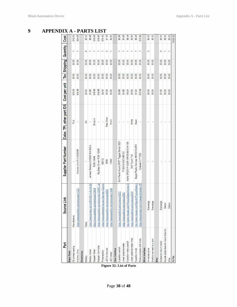
9 APPENDIX A - PARTS LIST
Figure 32: List of Parts
Blind-Automation Device Appendix B - CAD Models
Page 39 of 48
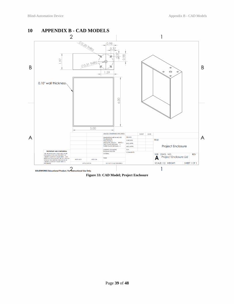
10 APPENDIX B - CAD MODELS
Figure 33: CAD Model; Project Enclosure
Blind-Automation Device Appendix c – Arduino Code
Page 40 of 48
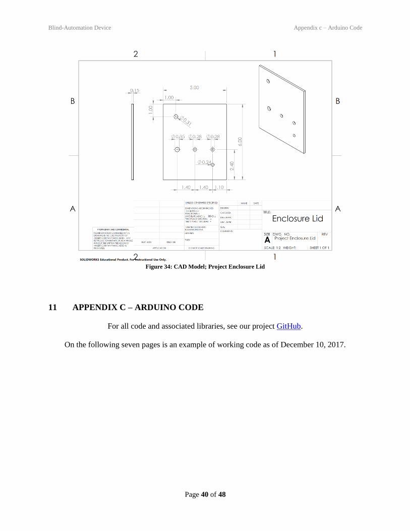
Figure 34: CAD Model; Project Enclosure Lid
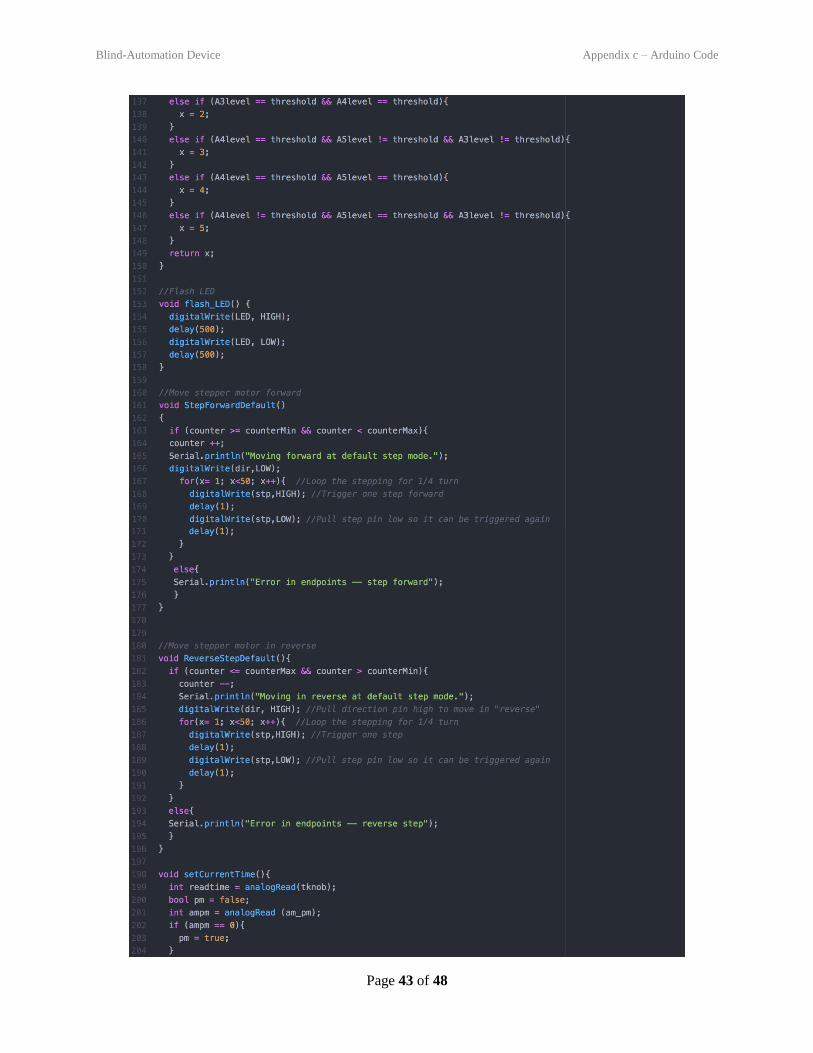
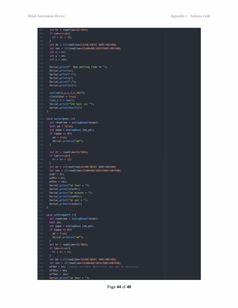
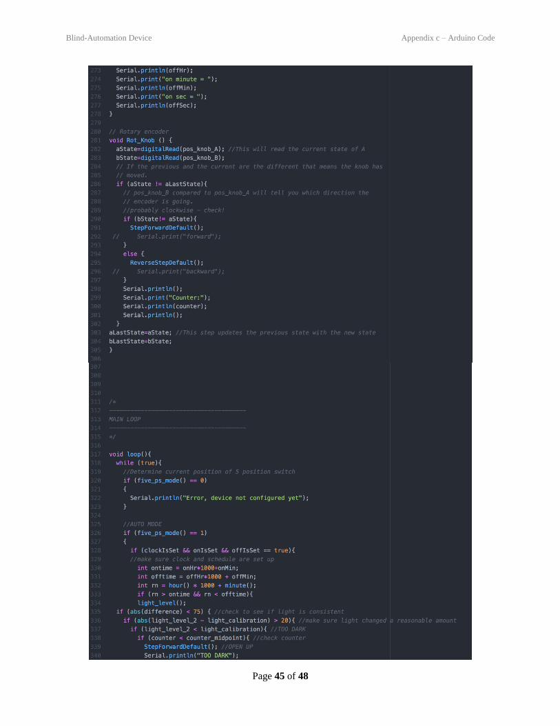
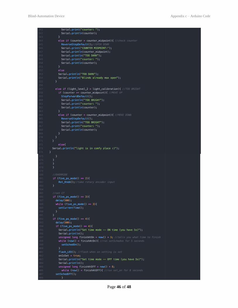
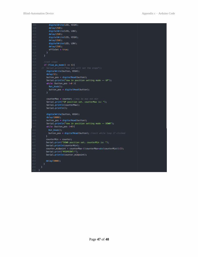
11 APPENDIX C – ARDUINO CODE
For all code and associated libraries, see our project GitHub.
On the following seven pages is an example of working code as of December 10, 2017.
Blind-Automation Device Appendix c – Arduino Code
Page 41 of 48
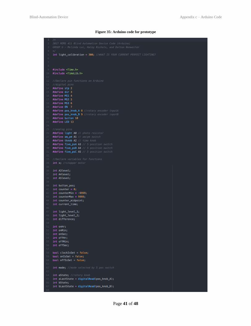
Figure 35: Arduino code for prototype
Blind-Automation Device Appendix c – Arduino Code
Page 42 of 48
Blind-Automation Device Appendix c – Arduino Code
Page 43 of 48
Blind-Automation Device Appendix c – Arduino Code
Page 44 of 48
Blind-Automation Device Appendix c – Arduino Code
Page 45 of 48
Blind-Automation Device Appendix c – Arduino Code
Page 46 of 48
Blind-Automation Device Appendix c – Arduino Code
Page 47 of 48
Blind-Automation Device Annotated Bibliography
Page 48 of 48
12 ANNOTATED BIBLIOGRAPHY
K, Toni. “Big Easy Driver Hookup Guide.” Big Easy Driver Hookup Guide, 5 May 2015,
learn.sparkfun.com/tutorials/big-easy-driver-hookup-guide.
Nedelkovski, Dejan. “How Rotary Encoder Works and How To Use It with Arduino.”
HowToMechatronics, 11 Oct. 2017, howtomechatronics.com/tutorials/arduino/rotary-encoder-
works-use-arduino/.
“US20130063065A1 - Automated Shade Control System Utilizing Brightness Modeling.” Google
Patents, Google,
patents.google.com/patent/US20130063065A1/en?q=blinds&sort=new&page=1.
“US5760558A - Solar-Powered, Wireless, Retrofittable, Automatic Controller for Venetian Blinds and
Similar Window Converings.” Google Patents, Google,
patents.google.com/patent/US5760558A/en.
“Scotch Extreme Mounting Tape, 1 in X 60 in, Black.” Scotch Extreme Mounting Tape, 1 in X 60 in,
Black | 3M United States, www.3m.com/3M/en_US/company-us/all-3m-products/~/Scotch-
Extreme-Mounting-Tape-1-in-X-60-in-Black?N=5002385+3294268145&rt=rud.
Related Documents


