Blended Wing Body Unmanned Aerial Vehicle Professors Jason Etele and Mostafa El Sayed 2017-2018

Welcome message from author
This document is posted to help you gain knowledge. Please leave a comment to let me know what you think about it! Share it to your friends and learn new things together.
Transcript
Blended Wing Body Unmanned Aerial Vehicle
Professors Jason Etele and Mostafa El Sayed
2017-2018
Blended Wing Body Unmanned Aerial Vehicle
Professors Jason Etele and Mostafa El Sayed
2017-2018

Blended Wing Body Unmanned Aerial Vehicle
Design Build Test Fly
high speed UAV
Mission:
BWB configuration Fully 3D printed VTOL capability

4
Blended Wing Body (BWB) Configuration
Boeing and NASA BWB X-48C
Blending
Bombardier CSERIES Flying Wing

5
B-2 Spirit - Northrop Grumman
First Flight: 17 July 1989
Military Applications:
F-117 Nighthawk - Lockheed
First Flight: 18 June 1981
Blended Wing Body (BWB) Configuration
Conceptual UAVs:
BAE systems - Taranis drone

Blended Wing Body (BWB) Configuration
6
Potential Benefits for Civil Aviation:
Al Bowers, NASA, 2000

Blended Wing Body (BWB) Configuration
Reduced wetted area to volume ratio by up to 33%:
friction drag fuel burn environmental impact Direct Operational Cost (DOC)
Increased lifting surface: about 20% increase in maximum Lift/Drag (L/D) ratio
Reduced noise: engines placement above the wing and streamlined geometry
Increased PAX capacity: Reduced Airport-Airspace congestion and reduced Fairs
12% DOC, 21% Fuel efficiency, 6% Gross weight, 17% Greenhouse gas emission 7
R.M. Martínez, 2014
Potential Benefits for Civil Aviation:

Multiscale Mechanics of Advanced Materials and 3D Printing
Applications
Aerospace: Aircraft, Spacecraft, UAVs Automotive Biomedical
Manufacturability
Blended Wing Body Unmanned Aerial Vehicle
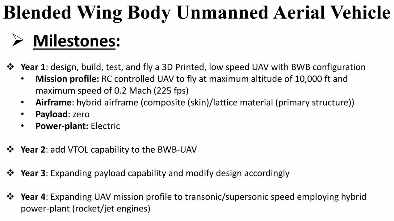
Year 1: design, build, test, and fly a 3D Printed, low speed UAV with BWB configuration • Mission profile: RC controlled UAV to fly at maximum altitude of 10,000 ft and
maximum speed of 0.2 Mach (225 fps) • Airframe: hybrid airframe (composite (skin)/lattice material (primary structure)) • Payload: zero • Power-plant: Electric
Year 2: add VTOL capability to the BWB-UAV
Year 3: Expanding payload capability and modify design accordingly
Year 4: Expanding UAV mission profile to transonic/supersonic speed employing hybrid power-plant (rocket/jet engines)
Milestones:

Aircraft Structural Development in Aerospace Industry

Questions
Related Documents


![[Article] Unmanned aerial vehicle remotely sensed datasets, a …geodata.kr/assets/pdf/7/journal-1-1-38.pdf · generated using rotary-wing UAV(unmanned aerial vehicle) system for](https://static.cupdf.com/doc/110x72/5e99aef244dfab24c12e8cfc/article-unmanned-aerial-vehicle-remotely-sensed-datasets-a-generated-using-rotary-wing.jpg)


