BLE112, BLE113 AND BLE121LR RANGE ANALYSIS APPLICATION NOTE Thursday, 15 May 2014 Version 1.1

Welcome message from author
This document is posted to help you gain knowledge. Please leave a comment to let me know what you think about it! Share it to your friends and learn new things together.
Transcript

BLE112, BLE113 AND BLE121LR RANGE ANALYSIS
APPLICATION NOTE
Thursday, 15 May 2014
Version 1.1
Bluegiga Technologies Oy
Copyright © 2000-2014 Bluegiga Technologies
All rights reserved.
Bluegiga Technologies assumes no responsibility for any errors which may appear in this manual. Furthermore, Bluegiga Technologies reserves the right to alter the hardware, software, and/or specifications detailed here at any time without notice and does not make any commitment to update the information contained here. Bluegiga’s products are not authorized for use as critical components in life support devices or systems.
The WRAP is a registered trademark of Bluegiga Technologies
The Bluetooth trademark is owned by the Bluetooth SIG Inc., USA and is licensed to Bluegiga Technologies. All other trademarks listed herein are owned by their respective owners.

Bluegiga Technologies Oy
VERSION HISTORY
Version Comment
1.0 Release
1.1 BLE121LR updated, BLE112 carrier measurement added

Bluegiga Technologies Oy
TABLE OF CONTENTS
1 Introduction ....................................................................................................................................................5
2 Range Comparison........................................................................................................................................6
2.1 BLE121LR Mounted to DKBLE ............................................................................................................6
2.2 DKBLE112 ............................................................................................................................................7
2.3 BLE112 Mounted to a Carrier Board ....................................................................................................8
2.4 DKBLE113 ............................................................................................................................................9
2.5 Module vs Phone Range ................................................................................................................... 10
2.6 How the Antenna Height from Ground Effects on the Range ............................................................ 10
3 How to Calculate the Range ....................................................................................................................... 13
4 Contact Information .................................................................................................................................... 14

Bluegiga Technologies Oy
Page 5 of 14
1 Introduction
2.4 GHz RF signal is strongly impacted by any obstacles within the RF path. Thus defining a range for a Bluetooth device is more or less question of how to determine the range. For example a radio located in a devices attached to human body has shorter range than a radio that is “floating” in free space because human body has an impact on the RF field. A person usually doesn’t point the device directly towards the transmitter so occasionally the body or other obstacles are within the RF path and will attenuate the received RF signal.
To determine the range for BLE112, BLE113 and BLE121LR, the modules were tested in an airfield using a data connection between the modules. The result does not guarantee practical range for real application. The result should be considered as maximum theoretical range. In a practical application the range can be much shorter because the orientation and height of the antenna can’t be controlled and also typically there are obstacles within the RF path which will attenuate the signal significantly.
In practical application the range is impacted by:
Persons / obstacles moving close to the antenna. This is because of multipath propagation and will have an impact even if the person is not in line of sight between the two radios.
Any obstacles within the RF path
PCB layout around the antenna (depending on the type of the antenna)
The shape of the PCB (depending on the type of the antenna)
The mechanical design of the end product
Because the range is impacted by many factors which are difficult to control, the practical range must be tested with the end product and the application should not be design based on the maximum theoretical range because the practical range will always be shorter.
Following chapter shows how the transmit power, receiver sensitivity and the radiation pattern converts to link budget and how the line of sight range can be estimated using plane earth loss calculation. Also the practical test results are shown to compare with the theoretical estimate.
Bluegiga Technologies Oy
Page 6 of 14
2 Range Comparison
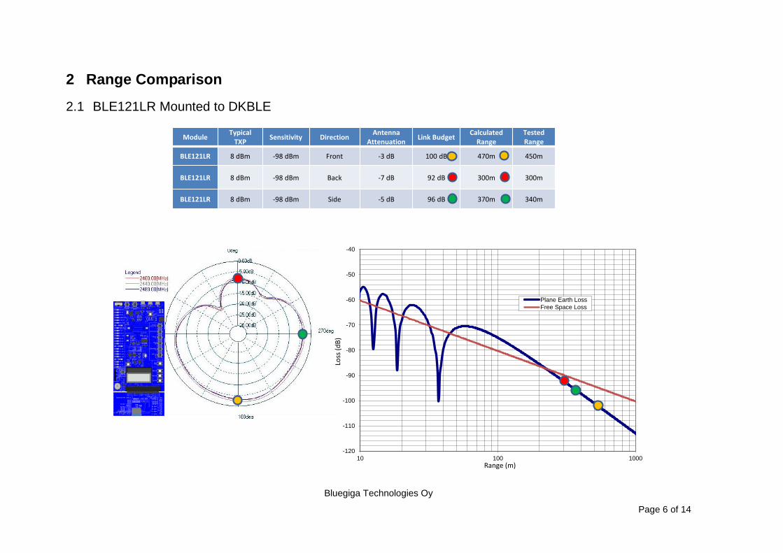
2.1 BLE121LR Mounted to DKBLE
ModuleTypical
TXPSensitivity Direction
Antenna Attenuation
Link BudgetCalculated
RangeTested Range
BLE121LR 8 dBm -98 dBm Front -3 dB 100 dB 470m 450m
BLE121LR 8 dBm -98 dBm Back -7 dB 92 dB 300m 300m
BLE121LR 8 dBm -98 dBm Side -5 dB 96 dB 370m 340m
-120
-110
-100
-90
-80
-70
-60
-50
-40
10 100 1000
Plane Earth Loss
Free Space Loss
Range (m)
Loss
(dB
)
Physical Dim
ensions of BLE121LR
14.7 mm
13.0 mm
4.8 mm
6.8 mm
8.4 mm
13.7 mm
3.9 mm
1.8 mm
1.8 mm
1.9 mm

Bluegiga Technologies Oy
Page 7 of 14
2.2 DKBLE112
ModuleTypical
TXPSensitivity Direction
AntennaAttenuation
(*Link Budget
Calculated Range
TestedRange (**
BLE112 3 dBm -91 dBm Front -14 dB 70 dB 20- 30 m 20 m
BLE112 3 dBm -91 dBm Back -6 dB 82 dB 160 m 150 m
BLE112 3 dBm -91 dBm Side -2 dB 90 dB 260 m -
-120
-110
-100
-90
-80
-70
-60
-50
-40
10 100 1000
Plane Earth Loss
Free Space Loss
*) The radiation pattern of a monopole chip antenna is strongly dependent on the motherboard layout. These numbersare measured with the DKBLE112
**) The range was tested with BLE112 carrier mounted to the DKBLE. Thus the radiation pattern does not necessarilymatch with the pattern measured with DKBLE112
Range (m)
Loss
(dB
)

Bluegiga Technologies Oy
Page 8 of 14
2.3 BLE112 Mounted to a Carrier Board
ModuleTypical
TXPSensitivity Direction
AntennaAttenuation
(*Link Budget
Calculated Range
TestedRange (**
BLE112 3 dBm -91 dBm Front -10 dB 74 dB 30 - 90 m -
BLE112 3 dBm -91 dBm Back -6dB 82 dB 160 m -
BLE112 3 dBm -91 dBm Side -2 dB 90 dB 260 m -
-120
-110
-100
-90
-80
-70
-60
-50
-40
10 100 1000
Plane Earth Loss
Free Space Loss
*) The radiation pattern of a monopole chip antenna is strongly dependent on the motherboard layout. These numbersare measured with the DKBLE112
**) The range was tested with BLE112 carrier mounted to the DKBLE. Thus the radiation pattern does not necessarilymatch with the pattern measured with DKBLE112
Range (m)
Loss
(dB
)

Bluegiga Technologies Oy
Page 9 of 14
2.4 DKBLE113
ModuleTypical
TXPSensitivity Direction
AntennaAttenuation
(*Link Budget
Calculated Range
TestedRange (*
BLE113 0 dBm -93 dBm Front -14 dB 69 dB 20-30 m -
BLE113 0 dBm -93 dBm Back -6 dB 81 dB 150 m -
BLE113 0 dBm -93 dBm Side -2 dB 89 dB 230 m -
-120
-110
-100
-90
-80
-70
-60
-50
-40
10 100 1000
Plane Earth Loss
Free Space Loss
*) The radiation pattern of a monopole chip antenna is strongly dependent on the motherboard layout. These numbersare measured with the DKBLE112. The radiation pattern of DKBLE113 can be asumed to be identical with DKBLE112 because of the same antenna in a similar layout.
Range (m)
Loss
(dB
)

Bluegiga Technologies Oy
Page 10 of 14
2.5 Module vs Phone Range
Following ranges were measured in an open field with antennas 1.5 meter above ground using the Heart Rate example. The range is the distance at which the remote device was able to still connect and remain the connection to the module.
Setup Tested Practical Line-of-Sight Range
BLE121LR vs iPod 250m – 300m
BLE121LR vs Nexus7 ~430m
BLE113 vs iPod 60m – 80m
BLE113 vs Nexus7 ~170m
Table 1: Tested practical ranges
2.6 How the Antenna Height from Ground Effects on the Range
In an open field the received power is a sum of the line-of-sight wave and the ground-reflected wave. Depending on the phase of the ground-reflected wave, it either amplifies or attenuates the total received power. For details, see chapter 3.
Following figures demonstrate how the actual plane earth loss (the path loss in an open field) behaves compared to the free space loss.

Bluegiga Technologies Oy
Page 11 of 14
-120
-110
-100
-90
-80
-70
-60
-50
-40
10 100 1000
Plane Earth Loss
Free Space Loss
Antennas 1.5m above ground

Bluegiga Technologies Oy
Page 12 of 14
-120
-110
-100
-90
-80
-70
-60
-50
-40
10 100 1000
Plane Earth Loss
Free Space Loss
Antennas 1.0m above ground
-120
-110
-100
-90
-80
-70
-60
-50
-40
10 100 1000
Plane Earth Loss
Free Space Loss
Antennas 0,5m above ground
Bluegiga Technologies Oy
Page 13 of 14
3 How to Calculate the Range
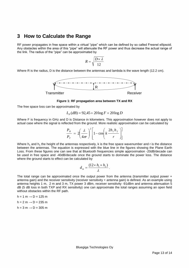
RF power propagates in free space within a virtual “pipe” which can be defined by so called Fresnel ellipsoid. Any obstacles within the area of this “pipe” will attenuate the RF power and thus decrease the actual range of the link. The radius of the “pipe” can be approximated by
12
DR
Where R is the radius, D is the distance between the antennas and lambda is the wave length (12.2 cm).
R
Transmitter Receiver
Figure 1: RF propagation area between TX and RX
The free space loss can be approximated by
DFdBLP log20log2045,92)(
Where F is frequency in GHz and D is Distance in kilometers. This approximation however does not apply to actual case where the signal is reflected from the ground. More realistic approximation can be calculated by
r
hhk
rP
P
T
R 21
2 2cos1
42
Where h1 and h1 the height of the antennas respectively, k is the free space wavenumber and r is the distance between the antennas. The equation is expressed with the blue line in the figures showing the Plane Earth Loss. From these figures one can see that at Bluetooth frequencies simple approximation -20dB/decade can be used in free space and -40dB/decade once the ground starts to dominate the power loss. The distance where the ground starts to effect can be calculated by
)12( 21 hhdm
.
The total range can be approximated once the output power from the antenna (transmitter output power + antenna gain) and the receiver sensitivity (receiver sensitivity + antenna gain) is defined. As an example using antenna heights 1 m, 2 m and 3 m, TX power 3 dBm, receiver sensitivity -91dBm and antenna attenuation 5 dB (5 dB loss in both TXP and RX sensitivity) one can approximate the total ranges assuming an open field without obstacles within the RF path.
h = 1 m → D = 125 m
h = 2 m → D = 235 m
h = 3 m → D = 305 m
Bluegiga Technologies Oy
Page 14 of 14
4 Contact Information
Sales: [email protected]
Technical support: http://www.bluegiga.com/support
Orders: [email protected]
WWW: www.bluegiga.com
Head Office / Finland:
Phone: +358-9-4355 060
Fax: +358-9-4355 0660
Sinikalliontie 5A
02630 ESPOO
FINLAND
Postal address / Finland:
P.O. BOX 120
02631 ESPOO
FINLAND
Sales Office / USA:
Phone: +1 770 291 2181
Fax: +1 770 291 2183
Bluegiga Technologies, Inc.
3235 Satellite Boulevard, Building 400, Suite 300
Duluth, GA, 30096, USA
Sales Office / Hong-Kong:
Bluegiga Technologies Ltd.
Phone: +852 3972 2186
Related Documents