1 UNESCO-NIGERIA TECHNICAL & VOCATIONAL EDUCATION REVITALISATION PROJECT-PHASE II YEAR 2 - SE MESTER I THEORY Version 1: December 2008 NATIONAL DIPLOMA IN BUILDING TECHNOLOGY BUILDING SERVICES COURSE CODE: BLD 207 Water Sources Water Sources Water Sources Water Sources

BLD 207 Building Services Final Combined
Oct 21, 2015
Welcome message from author
This document is posted to help you gain knowledge. Please leave a comment to let me know what you think about it! Share it to your friends and learn new things together.
Transcript

1
UNESCO-NIGERIA TECHNICAL & VOCATIONAL
EDUCATION REVITALISATION PROJECT-PHASE II
YEAR 2 - SE MESTER I
THEORY
Version 1: December 2008
NATIONAL DIPLOMA IN
BUILDING TECHNOLOGY
BUILDING SERVICES
COURSE CODE: BLD 207
Water SourcesWater SourcesWater SourcesWater Sources

2
TABLE OF CONTENTS
WEEK1: THE SOURCES, QUALITY AND CLASSIFICATION OF W ATER
1.1 Course Introduction to Students
WEEK2: THE SOURCES, QUALITY AND CLASSIFICATION OF W ATER
1.1 Sources of Water
WEEK3 : THE SOURCES, QUALITY AND CLASSIFICATION OF WATER
1.2 State the Quality of Water from the Sources in 1.1
1.3 State the Two Classes of Water
1.4 Describe the Methods of Purification of Water
WEEK 4: THE SYSTEM OF DISTRIBUTION OF PIPE-WORK FOR DOMESTIC COLD WATER SUPPLY.
2.1 Illustrate the Direct and Indirect Method of Water Supply
2.2 Identify the Sizes and Types of Pipes Used Along the Distribution System
2.3 Describe with Sketches Cold Water Supply System
2.4 Describe Means of Providing Drinking Water
2.5 Differentiate Between Service, Communication and Other Pipes
WEEK 5: WATER DISTRIBUTION SYSTEMS 2
1.4 Water Purification/Treatment Flow chart
2.5 Differences between Distribution Lines
2.0 Water Supply and the African Peculiar Experience

3
WEEK 6 WATER DISTRIBUTION SYSTEMS 3
2.0 Water Connection/Distribution Details in Drawings
WEEK 7: HOT WATER SUPPLY
WEEK 8: HOT WATER SUPPLY2
3.3 Precaution Against Dead Leg
WEEK 9: SANITARY APPLIANCES AND FITTINGS
4.1 Sanitary Appliances Description
WEEK 10: SANITARY APPLIANCES AND FITTINGS 2
4.1 -2 Taps and Valves
4.3 Construction Requirements for Fittings
WEEK 11: DRAINAGE SYSTEM USED IN BUILDINGS
WEEK 12: DRAINAGE SYSTEM USED IN BUILDINGS 2.
WEEK 13: DAYLIGHT AND ARTIFICIAL LIGHTING
WEEK 14: ELECTRICAL FITTINGS AND CONTROL
WEEK 15: REVISION AND CLASS WORK
7.5 Design and Installation Practice for Simple Building

4
WEEK1: COURSE INTRODUCTION/OVERVIEW (1.0)
INTRODUCTION
Building Services is a course that deals with the provision of facilities to buildings to make such
buildings comfortable for human use. A building as a basic structure only offers protection
against adverse weather conditions, such as rainfall, snowfall, sunshine, wind etc.
For the convenience of the users of buildings, more is required of this basic structure; these
requirements include among others toilet facilities, this brings up the need for collection,
transportation, disposal and treatment of waste.
The need for water to make this modern toilet functional also makes it imperative to provide
water.
The waste generated in addition to the collection and disposal of storm water also brings up the
issue of drainage systems in building.
The heat generated by the sun’s radiation causes a lot of inconvenience to building users in form
of raised body temperature; this situation requires adequate ventilation – a good air
circulation/movement. The natural form of circulation might not be adequate hence the need for
means of artificial air circulation that can only be made possible by the use of energy the most
common of which is electricity. Closely linked to this is the need to provide lighting to a
building. Building being basically a boxlike enclosure usually requires lighting to allow for
visibility of the interior, this is only made possible by either natural lighting – obtained by the
creation of openings in building, or artificial lighting obtained via the use of electricity or any
other sources of energy.
The foregoing basically is what services to a building are all about. Put in a different form
Building services or general services are those provisions in and around buildings that make the
use of the built environment convenient for users.
5
Some of the facilities provided in around buildings to make them functionally acceptable are as
explained below:
Water Supply
Water is one of the basic human needs. That water is needed cannot be over emphasized, the
availability of water on earth is also not in question. What is usually the problem is the quality,
the sources, the supply of potable water after treatment and the form/convenience by which the
supply gets to the users.
Building services in this respect seek to create an understanding of the real meaning of water, the
sources, the quality, the purification/treatment/ storage and supply to ensure adequacy and
availability all time round.
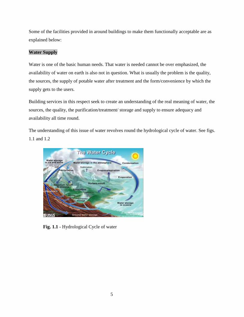
The understanding of this issue of water revolves round the hydrological cycle of water. See figs.
1.1 and 1.2
Fig. 1.1 - Hydrological Cycle of water

6
Fig. 1.2 - Surface/Underground water
Water Cycle Description
The water cycle has no starting or ending point. The sun, which drives the water cycle, heats
water in the oceans. Some of it evaporates as vapor into the air. Ice and snow can sublimate
directly into water vapor. Rising air currents take the vapor up into the atmosphere, along with
water from evapo-transpiration, which is water transpired from plants and evaporated from the
soil. The vapor rises into the air where cooler temperatures cause it to condense into clouds. Air
currents move clouds around the globe; cloud particles collide, grow, and fall out of the sky as
precipitation. Some precipitation falls as snow and can accumulate as ice caps and glaciers,
which can store frozen water for thousands of years. Snow packs in warmer climates often thaw
and melt when spring arrives, and the melted water flows overland as snowmelt. Most
precipitation falls back into the oceans or onto land, where, due to gravity, the precipitation flows
over the ground as surface runoff. A portion of runoff enters rivers in valleys in the landscape,
with stream flow moving water towards the oceans. Runoff, and ground-water seepage,
accumulate and are stored as freshwater in lakes. Not all runoff flows into rivers. Much of it
soaks into the ground as infiltration. Some water infiltrates deep into the ground and replenishes
aquifers (saturated subsurface rock), which store huge amounts of freshwater for long periods of
time. Some infiltration stays close to the land surface and can seep back into surface-water
bodies (and the ocean) as ground-water discharge, and some ground water finds openings in the

7
land surface and emerges as freshwater springs. Over time, the water continues flowing, some to
re-enter the ocean, where the water cycle renews itself.
The different processes are as follows:
• Precipitation is condensed water vapor that falls to the Earth's surface. Most precipitation
occurs as rain, but also includes snow, hail, fog drip, graupel, and sleet. Approximately
505,000 km³ of water fall as precipitation each year, 398,000 km³ of it over the oceans.[2]
• Canopy interception is the precipitation that is intercepted by plant foliage and eventually
evaporates back to the atmosphere rather than falling to the ground.
• Snowmelt refers to the runoff produced by melting snow.
• Runoff includes the variety of ways by which water moves across the land. This includes
both surface runoff and channel runoff. As it flows, the water may infiltrate into the ground,
evaporate into the air, become stored in lakes or reservoirs, or be extracted for agricultural or
other human uses.
• Infiltration is the flow of water from the ground surface into the ground. Once infiltrated, the
water becomes soil moisture or groundwater.
• Subsurface Flow is the flow of water underground, in the vadose zone and aquifers.
Subsurface water may return to the surface (eg. as a spring or by being pumped) or
eventually seep into the oceans. Water returns to the land surface at lower elevation than
where it infiltrated, under the force of gravity or gravity induced pressures. Groundwater
tends to move slowly, and is replenished slowly, so it can remain in aquifers for thousands of
years.
• Evaporation is the transformation of water from liquid to gas phases as it moves from the
ground or bodies of water into the overlying atmosphere.[4] The source of energy for
evaporation is primarily solar radiation. Evaporation often implicitly includes transpiration

8
from plants, though together they are specifically referred to as evapo-transpiration. Total
annual evapo-transpiration amounts to approximately 505,000 km³ of water, 434,000 km³ of
which evaporates from the oceans. Sublimation is the state change directly from solid water (snow
or ice) to water vapor. Advection is the movement of water — in solid, liquid, or vapour states —
through the atmosphere. Without advection, water that evaporated over the oceans could not
precipitate over land.[7]
• Condensation is the transformation of water vapour to liquid water droplets in the air, producing
clouds and fog.[8]
Reservoirs
In the context of the water cycle, a reservoir represents the water contained in different steps
within the cycle. The largest reservoir is the collection of oceans, accounting for 97% of the
Earth's water. The next largest quantity (2%) is stored in solid form in the ice caps and glaciers.
This small amount accounts for approximately 75% of all fresh water reserves on the planet. The
water contained within all living organisms represents the smallest reservoir.
The volumes of water in the fresh water reservoirs, particularly those that are available for
human use, are important water resources.
In hydrology, residence times can be estimated in two ways. The more common method relies on
the principle of conservation of mass and assumes the amount of water in a given reservoir is
roughly constant. With this method, residence times are estimated by dividing the volume of the
reservoir by the rate by which water either enters or exits the reservoir. Conceptually, this is
equivalent to timing how long it would take the reservoir to become filled from empty if no
water were to leave (or how long it would take the reservoir to empty from full if no water were
to enter).
An alternative method to estimate residence times, gaining in popularity particularly for dating
groundwater, is the use of isotopic techniques. This is done in the subfield of isotope hydrology.

9
Common Water Treatment Techniques and Devices:
Once contamination is detected in a drinking water supply it is important to use the proper treatment device to remove the contaminant. The following section is intended as a guide to help in the selection of a treatment device. Before buying a treatment device have the water supply tested for contamination and consult a specialist when selecting the best treatment device. If the specific contaminant is known the following methods and devices are used for treatment:
(a) Activated Alumina (b) Activated Carbon ( c) Aeration
(d) Anion Exchange
(e) Chemical Precipitation
(f) Chlorination
(g) Distillation
(f) Ion Exhange
(g) Mechanical Filtration
(g) Neutralizing Filters
(h) Oxidizing Filters
(i) Reverse Osmosis
(j) Ultraviolet
Common Aesthetic Problems and Solutions
Symptom Probable Cause Treatments
Hard water deposits on kettles,
pots, hot water heaters,
humidifiers
Excess calcium
Water softener
Reverse Osmosis
Distillation
Rusty red or brown staining of
fixtures or laundry and/or your
water has a metallic taste
Excess iron
Water softener
Whole house iron filter
Distillation
10
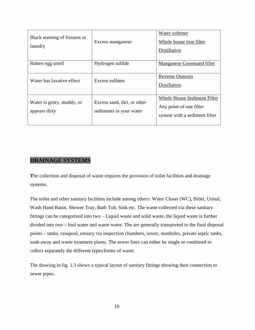
Black staining of fixtures or
laundry Excess manganese
Water softener
Whole house iron filter
Distillation
Rotten egg smell Hydrogen sulfide Manganese Greensand filter
Water has laxative effect Excess sulfates Reverse Osmosis
Distillation
Water is gritty, muddy, or
appears dirty
Excess sand, dirt, or other
sediments in your water
Whole House Sediment Filter
Any point-of-use filter
system with a sediment filter
DRAINAGE SYSTEMS
The collection and disposal of waste requires the provision of toilet facilities and drainage
systems.
The toilet and other sanitary facilities include among others: Water Closet (WC), Bidet, Urinal,
Wash Hand Basin, Shower Tray, Bath Tub, Sink etc. The waste collected via these sanitary
fittings can be categorized into two – Liquid waste and solid waste, the liquid waste is further
divided into two – foul water and waste water. The are generally transported to the final disposal
points – tanks, cesspool, estuary via inspection chambers, sewer, manholes, private septic tanks,
soak-away and waste treatment plants. The sewer lines can either be single or combined to
collect separately the different types/forms of waste.
The drawing in fig. 1.3 shows a typical layout of sanitary fittings showing their connection to
sewer pipes.

11
Fig. 1.3 – Typical layout of sanitary drainage system
DAYLIGHT AND ARTIFICIAL LIGHT
Building as an enclosure requires the provision of light in the interior to offer adequate
illumination at various time and level of desired brightness. This is usually taken care of by a
careful provision of openings in building to admit daylight and the provision of artificial (man
made) light in the form various energy driven forms of illuminants. The careful and intelligent
integration of these two forms of illumination is a subject matter needing adequate
understanding. This is to be discussed under the following subheads:
• Artificial and natural lighting methods
• How artificial lighting is provided in a house
• The integration of natural and artificial lighting in a house.
12
• Electrical source of energy to power artificial lighting
• Cables used in power distribution and general connections
• Electrical fittings
• Construction provisions made for electrical fittings
• Simple electrical circuit system used in residential houses.
• Typical electrical wiring in low rise building.
• Regulations - I.E.E. (Institution of Electrical Engineering)
- N.E.P.A. (National Electricity Power Authority)
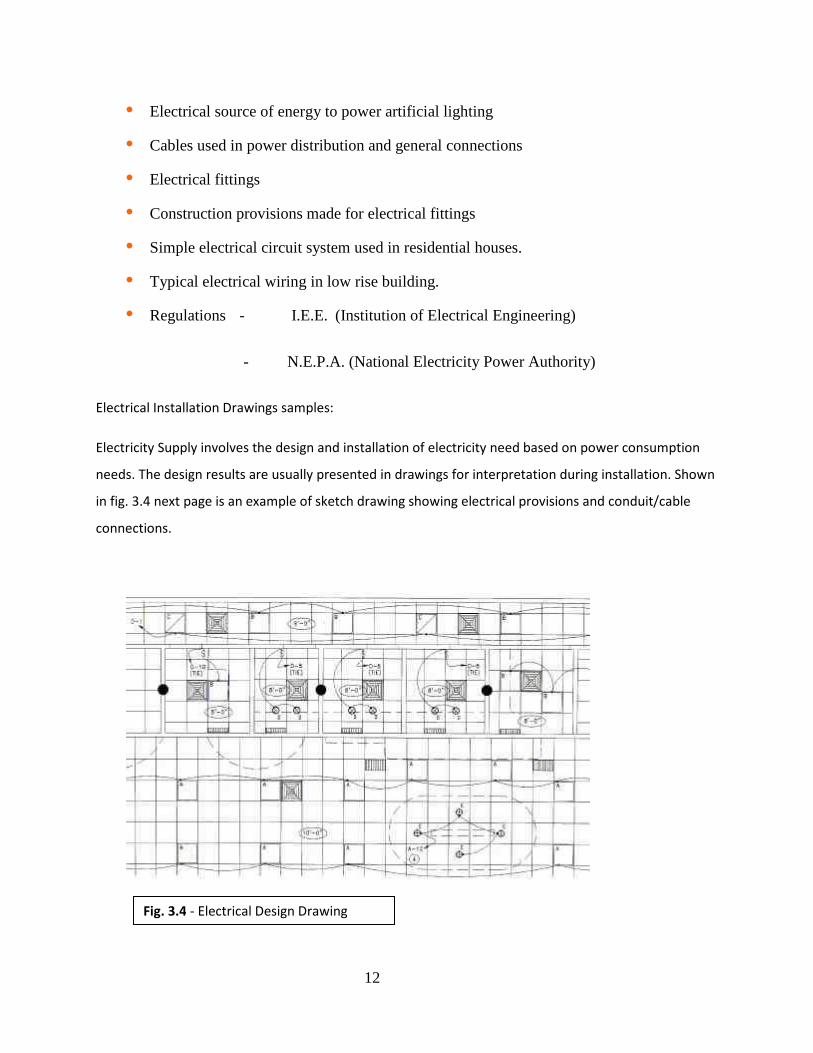
Electrical Installation Drawings samples:
Electricity Supply involves the design and installation of electricity need based on power consumption
needs. The design results are usually presented in drawings for interpretation during installation. Shown
in fig. 3.4 next page is an example of sketch drawing showing electrical provisions and conduit/cable
connections.
Fig. 3.4 - Electrical Design Drawing

13
WEEK2: SOURCES,QUALITY AND CLASSIFICATION OF WATER 2
Sources of Water
Water is obtained generally within the hydrological cycle of water – a term used to refer to the
journey of water in the earth system. Because this journey is cyclic in nature, meaning that it
starts from one point and end at another point only to continue on its journey again from the
same starting point. It starts with rainfall from the cloud in the form of precipitation, turn into
run-offs to form stream, river and ground water from where we obtain both deep and shallow
wells. In addition to these we have spring water, borehole water that that are obtained from water
at the water table point.
The foregoing lead to having a list of sources of water as follows:
1. Stream
2. River
3. Ocean
4. Shallow Well
5. Driven wells
6. Deep Well
7. Bore Hole
8. Spring
Stream is simply described as a small river: a narrow and shallow river
River is a large natural channel of water: a natural stream of water that flows through land and
empties into a body of water such as an ocean or lake

14
Ocean is a large sea: a large expanse of salt water, especially any of the Earth's five main such
areas, the Atlantic, Pacific, Indian, Arctic, and Antarctic oceans.
The oceans occupy huge regions of the Earth's surface, and their boundaries are usually
established by continental land masses and ridges in the ocean floor.
Types of water wells
Water wells are means by which assess to ground water is achieved. It involves digging by
different means into the ground, the pressure difference created by the space within the ground
lead to the movement of water from the surrounding into the well. The depth of well depends on
the water level, the degree of saturation of the ground and the water table position. As shown in
figures 2.1 to 2.5
Dug wells
Fig. 2.1 – Interior of Dug well - brick lined water well
Until recent centuries, all artificial wells were pump-less dug wells of varying degrees of
formality. Their indispensability has produced numerous literary references, literal and
figurative, to them, including the Christian Bible story of Jesus meeting a woman at Jacob's well
(John 4:6) and the "Ding Dong Bell" nursery rhyme about a cat in a well.

15
Such primitive dug wells were excavations with diameters large enough to accommodate men
with shovels digging down to below the water table. Relatively formal versions tended to be
lined with laid stones or brick; extending this lining into a wall around the well presumably
served to reduce both contamination and injuries by falling into the well. The iconic American
farm well features a peaked roof above the wall, reducing airborne contamination, and a cranked
windlass, mounted between the two roof-supporting members, for raising and lowering a bucket
to obtain water.
More modern dug wells may be hand pumped, especially in developing countries.
Note that the term "shallow well" is not a synonym for dug well, and may actually be quite deep
- see Aquifer type, below.
Driven wells
Driven wells may be very simply created in unconsolidated material with a "well point", which
consists of a hardened drive point and a screen (perforated pipe). The point is simply hammered
into the ground, usually with a tripod and "driver", with pipe sections added as needed. A driver
is a weighted pipe that slides over the pipe being driven and is repeatedly dropped on it. When
groundwater is encountered, the well is washed of sediment and a pump installed.

16
Borehole/Drilled wells
Fig. 2.2 - Cable tool water well drilling rig.
Drilled wells can get water from a much deeper level by mechanical drilling.
Drilled wells with electric pumps are currently used throughout the world, typically in rural or
sparsely populated areas, though many urban areas are supplied partly by municipal wells.
Drilled wells are typically created using either top-head rotary style, table rotary, or cable tool
drilling machines, all of which use drilling stems that are turned to create a cutting action in the
formation, hence the term 'drilling'. Most shallow well drilling machines are mounted on large
trucks, trailers, or tracked vehicle carriages. Water wells typically range from 20 to 600 feet
(180 m), but in some areas can go deeper than 3,000 feet (910 m).
Rotary drilling machines use a segmented steel drilling string, typically made up of 20-foot
(6.1 m) sections of steel tubing that is threaded together, with a bit or other drilling device at the

17
bottom end. Some rotary drilling machines are designed to install (by driving or drilling) a steel
casing into the well in conjunction with the drilling of the actual bore hole. Air and/or water is
used as a circulation fluid to displace cuttings and cool bits during the drilling. Another form of
rotary style drilling, termed 'mud rotary', makes use of a specially made mud, or drilling fluid,
which is constantly being altered during the drill so that it can consistently create enough
hydraulic pressure to hold the side walls of the bore hole open, regardless of the presence of a
casing in the well. Typically, boreholes drilled into solid rock are not cased until after the drilling
process is completed, regardless of the machinery used.
The oldest form of drilling machinery is the Cable Tool, still used today. Specifically designed to
raise and lower a bit into the bore hole, the 'spudding' of the drill causes the bit to be raised and
dropped onto the bottom of the hole, and the design of the cable causes the bit to twist at
approximately 1/4 revolution per drop, thereby creating a drilling action. Unlike rotary drilling,
cable tool drilling requires the drilling action to be stopped so that the bore hole can be bailed or
emptied of drilled cuttings.
Drilled wells are typically cased with a factory-made pipe, typically steel (in air rotary or cable
tool drilling) or plastic/PVC (in mud rotary wells, also present in wells drilled into solid rock).
The casing is constructed by welding, either chemically or thermodynamically, segments of
casing together. If the casing is installed during the drilling, most drills will drive the casing into
the ground as the bore hole advances, while some newer machines will actually allow for the
casing to be rotated and drilled into the formation in a similar manner as the bit advancing just
below. PVC or plastic is typically welded and then lowered into the drilled well, vertically
stacked with their ends nested and either glued or splined together. The sections of casing are
usually 20' (6 m) or more in length, and 6" - 12" (15 to 30 cm) in diameter, depending on the
intended use of the well and local groundwater conditions.
Surface contamination of wells in the United States is typically controlled by the use of a 'surface
seal'. A large hole is drilled to a predetermined depth or to a confining formation (clay or
bedrock, for example), and then a smaller hole for the well is completed from that point forward.
The well is typically cased from the surface down into the smaller hole with a casing that is the
18
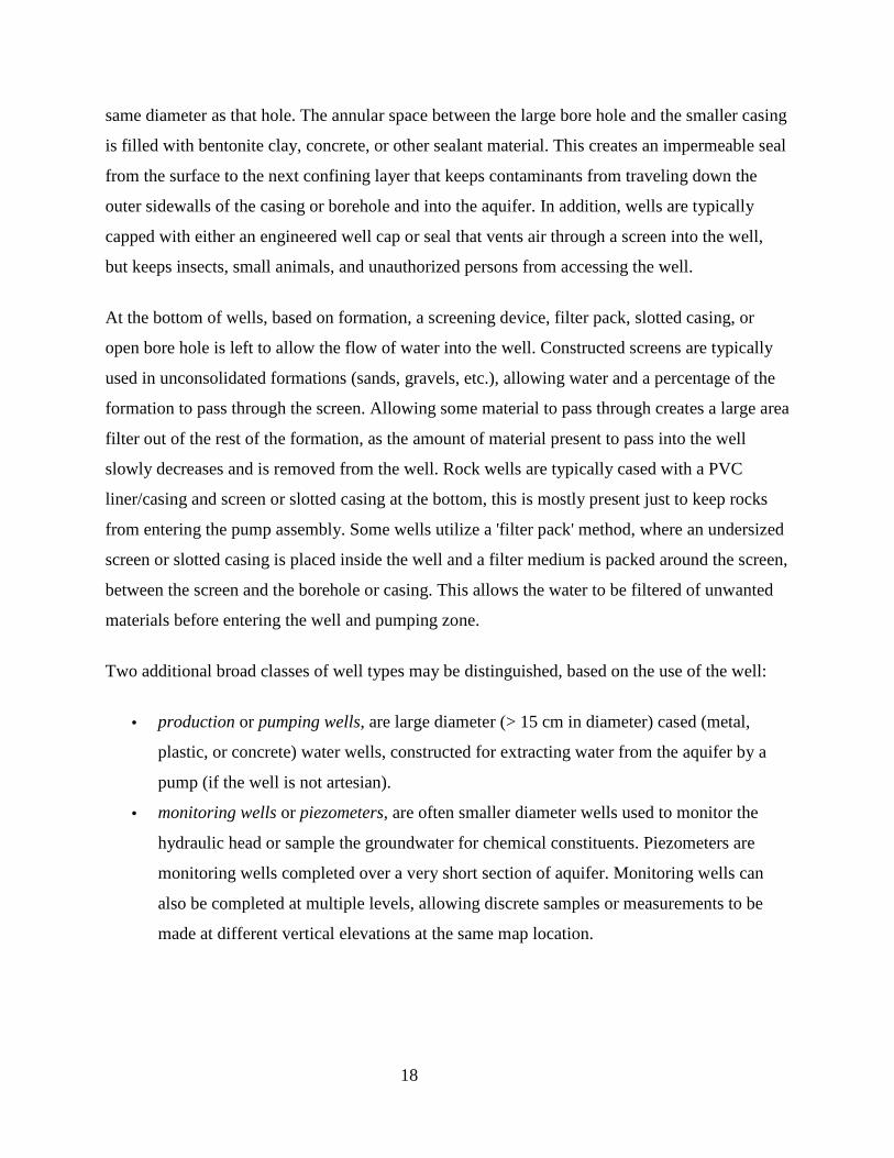
same diameter as that hole. The annular space between the large bore hole and the smaller casing
is filled with bentonite clay, concrete, or other sealant material. This creates an impermeable seal
from the surface to the next confining layer that keeps contaminants from traveling down the
outer sidewalls of the casing or borehole and into the aquifer. In addition, wells are typically
capped with either an engineered well cap or seal that vents air through a screen into the well,
but keeps insects, small animals, and unauthorized persons from accessing the well.
At the bottom of wells, based on formation, a screening device, filter pack, slotted casing, or
open bore hole is left to allow the flow of water into the well. Constructed screens are typically
used in unconsolidated formations (sands, gravels, etc.), allowing water and a percentage of the
formation to pass through the screen. Allowing some material to pass through creates a large area
filter out of the rest of the formation, as the amount of material present to pass into the well
slowly decreases and is removed from the well. Rock wells are typically cased with a PVC
liner/casing and screen or slotted casing at the bottom, this is mostly present just to keep rocks
from entering the pump assembly. Some wells utilize a 'filter pack' method, where an undersized
screen or slotted casing is placed inside the well and a filter medium is packed around the screen,
between the screen and the borehole or casing. This allows the water to be filtered of unwanted
materials before entering the well and pumping zone.
Two additional broad classes of well types may be distinguished, based on the use of the well:
• production or pumping wells, are large diameter (> 15 cm in diameter) cased (metal,
plastic, or concrete) water wells, constructed for extracting water from the aquifer by a
pump (if the well is not artesian).
• monitoring wells or piezometers, are often smaller diameter wells used to monitor the
hydraulic head or sample the groundwater for chemical constituents. Piezometers are
monitoring wells completed over a very short section of aquifer. Monitoring wells can
also be completed at multiple levels, allowing discrete samples or measurements to be
made at different vertical elevations at the same map location.

19
Obviously, a well constructed for pumping groundwater can be used passively as a monitoring
well and a small diameter well can be pumped, but this distinction by use is common.
Well Water Quality and Hygiene
Fig. 2.3 – Concrete lined well in Africa
Shallow pumping wells can often supply drinking water at a very low cost, but because
impurities from the surface easily reach shallow sources, a greater risk of contamination occurs
for these wells when they are compared to deeper wells. In shallow and deep wells, the water
requires pumping to the surface; in artesian wells, conversely, water usually rises to a greater
level than the land surface when extracted from a deep source.
Well water for personal use is often filtered with reverse osmosis water processors; this process
can remove very small particles. A simple, effective way of killing micro organisms is to boil the
water (although, unless in contact with surface water or near areas where treated wastewater is
being recharged, groundwater tends to be free of micro organisms). Alternately the addition of
1/8 teaspoon (0.625 mL) of bleach to a gallon (3.8 L) of water will disinfect it after a half hour.
Contamination of groundwater from surface and subsurface sources can usually be dramatically
reduced by correctly centering the casing during construction and filling the casing annulus with
an appropriate sealing material. The sealing material (grout) should be placed from immediately
above the production zone back to surface, because, in the absence of a correctly constructed
20
casing seal, contaminated fluid can travel into the well through the casing annulus. Centering
devices are important (usually 1 per length of casing or at maximum intervals of 30 feet/9 m) to
ensure that the grouted annular space is of even thickness.
Anthropogenic contamination
Contamination related to human activity is a common problem with groundwater. For example,
benzene, toluene, ethylbenzene, and total xylenes (BTEX), which come from gasoline refining,
and methyl-tert-butyl-ether (MTBE), which is a fuel additive, are common contaminants in
urbanized areas, often as the result of leaking underground storage tanks. Many industrial
solvents also are common groundwater contaminants, which may enter groundwater through
leaks, accidental spills or intentional dumping. Military facilities also produce considerable
amounts of groundwater contamination, often in the form of solvents like trichloroethylene
(TCE).[3] Cleanup of contaminated groundwater tends to be very costly. Effective remediation of
groundwater is generally very difficult.
Natural contaminants
Some very common constituents of well water are natural contaminants created by subsurface
mineral concentrations. Common examples include iron, magnesium and calcium. Large
quantities of magnesium and calcium ions cause what is known as "hard water". Certain
contaminants such as arsenic and radon are considered carcinogenic. [2] and therefore chronic
contaminants. Other natural constituents of concern are nitrates and Coliform bacteria, both of
which are considered acute contaminants and may seriously sicken persons considered to be "at
risk", mainly the elderly, infirm and infants. Also of consequence can be radionuclides such as
radium, uranium and other elements. Upon the construction of a new test well, it is considered
best practice to invest in a complete battery of chemical tests on the well water in question.
Point-of-use treatment is available for individual properties and treatment plants are often
constructed for municipal water supplies that suffer from contamination. Most of these treatment
methods involve the filtration of the contaminants of concern, and additional protection may be
garnered by installing well-casing screens only at depths where contamination is not present.
21
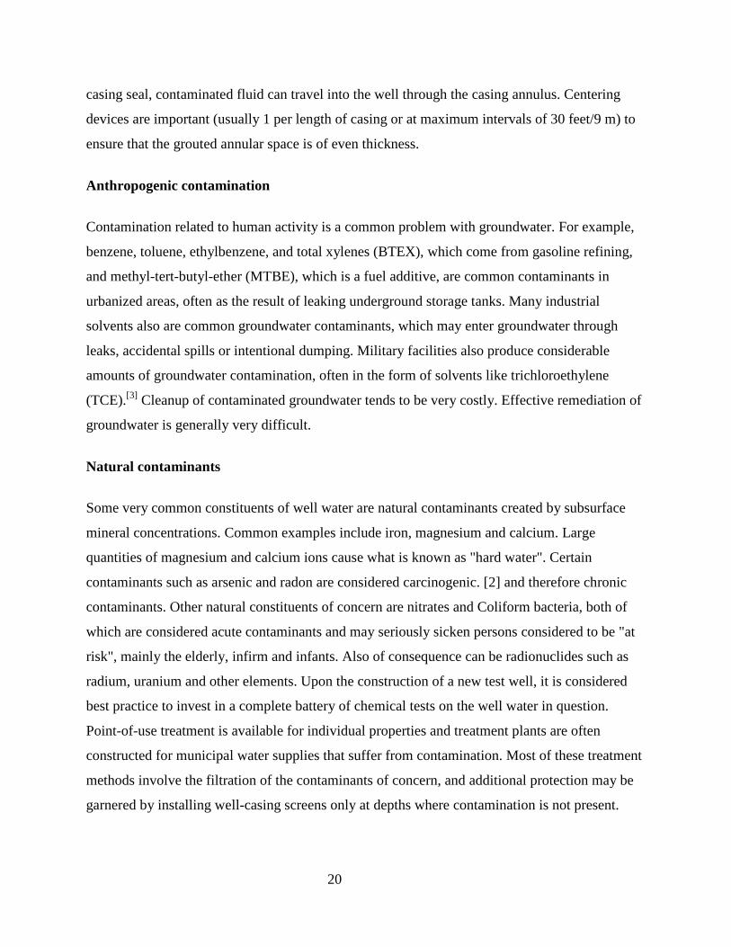
Ancient well
fig. 2.4 – Old dug well
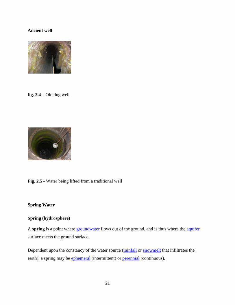
Fig. 2.5 - Water being lifted from a traditional well
Spring Water
Spring (hydrosphere)
A spring is a point where groundwater flows out of the ground, and is thus where the aquifer
surface meets the ground surface.
Dependent upon the constancy of the water source (rainfall or snowmelt that infiltrates the
earth), a spring may be ephemeral (intermittent) or perennial (continuous).
22
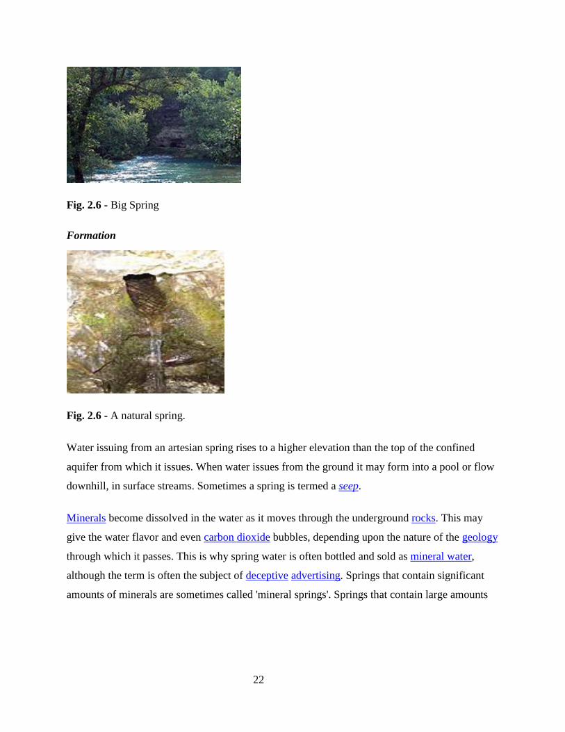
Fig. 2.6 - Big Spring
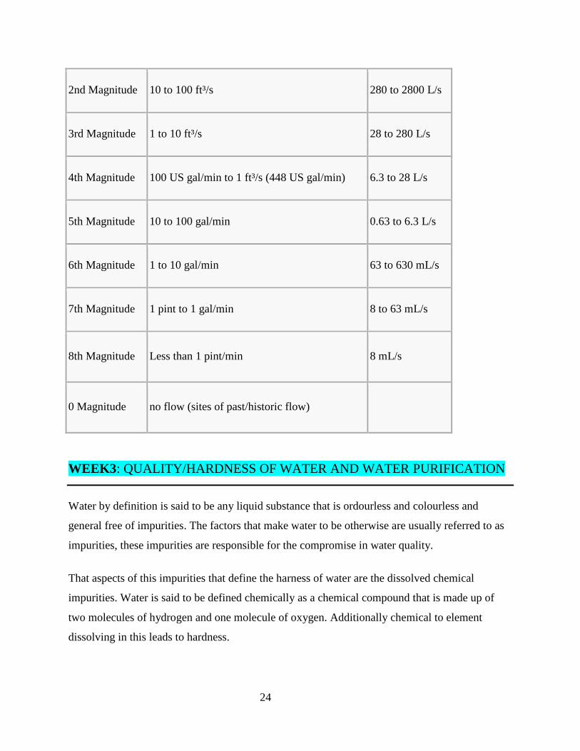
Formation
Fig. 2.6 - A natural spring.
Water issuing from an artesian spring rises to a higher elevation than the top of the confined
aquifer from which it issues. When water issues from the ground it may form into a pool or flow
downhill, in surface streams. Sometimes a spring is termed a seep.
Minerals become dissolved in the water as it moves through the underground rocks. This may
give the water flavor and even carbon dioxide bubbles, depending upon the nature of the geology
through which it passes. This is why spring water is often bottled and sold as mineral water,
although the term is often the subject of deceptive advertising. Springs that contain significant
amounts of minerals are sometimes called 'mineral springs'. Springs that contain large amounts

23
of dissolved sodium salts, mostly sodium carbonate, are called 'soda springs'. Many resorts have
developed around mineral springs known as spa towns.
Fig. 2.7 – Water Pool from spring.
A stream carrying the outflow of a spring to a nearby primary stream is called a spring branch or
run. The cool water of a spring and its branch may harbor species such as certain trout that are
otherwise ill-suited for a warmer local climate.
Water emanating from karst topography is another type of spring, often called a resurgence as
much of the water may come from one or more sinkholes at a higher altitude. Karst springs
generally are not subjected to as great a degree of ground filtering as spring water which may
have continuously passed through soils or a porous aquifer.
Classification
Springs are often classified by the volume of the water they discharge. The largest springs are called "first-magnitude," defined as springs that discharge water at a rate of at least 2800 L/s. The scale for spring flow is as follows:
Magnitude Flow (ft³/s, gal/min, pint/min) Flow (L/s)
1st Magnitude > 100 ft³/s 2800 L/s
24
2nd Magnitude 10 to 100 ft³/s 280 to 2800 L/s
3rd Magnitude 1 to 10 ft³/s 28 to 280 L/s
4th Magnitude 100 US gal/min to 1 ft³/s (448 US gal/min) 6.3 to 28 L/s
5th Magnitude 10 to 100 gal/min 0.63 to 6.3 L/s
6th Magnitude 1 to 10 gal/min 63 to 630 mL/s
7th Magnitude 1 pint to 1 gal/min 8 to 63 mL/s
8th Magnitude Less than 1 pint/min 8 mL/s
0 Magnitude no flow (sites of past/historic flow)
WEEK3 : QUALITY/HARDNESS OF WATER AND WATER PURIFICATION
Water by definition is said to be any liquid substance that is ordourless and colourless and
general free of impurities. The factors that make water to be otherwise are usually referred to as
impurities, these impurities are responsible for the compromise in water quality.
That aspects of this impurities that define the harness of water are the dissolved chemical
impurities. Water is said to be defined chemically as a chemical compound that is made up of
two molecules of hydrogen and one molecule of oxygen. Additionally chemical to element
dissolving in this leads to hardness.

25
Hardness of water can in part be said to be the state of water that make it impure as a result bad
taste feeling and behaviour in the presence of soap. It usually make it impossible for soap to
lather hence compromising its ability to clean.
Softness on the other hand is almost the opposite of hardness a state of water devoid of hardness
that make it wash or soap friendly. Sodium Chloride (NaCl) that is contained in soap is usually
rendered ineffective in the presence of such dissolve chemicals as Calcium (Ca), Iron (Fe),
Manganese (Mn) etc.
Water from almost all the sources is said to be impure for human consumption, therefore steps
are usually taken to make water pure, which means to get rid of the dissolved/suspended physical
and chemical impurities.
The following methods are usually adopted for water purification:
1. Sedimentation
2. Filtration
3. Aeration
4. Heat Treatment
5. Chemical Treatment
Water treatment describes those processes used to make water more acceptable for a desired
end-use. These can include use as drinking water, industrial processes, medical and many other
uses. The goal of all water treatment process is to remove existing contaminants in the water, of
reduce the concentration of such contaminants so it becomes fit for its desired end-use. One such
use is returning water that has been used back into the natural environment without adverse
ecological impact.
The processes involved in treating water may be physical such as settling, chemical such as
disinfection or coagulation, or biological such as lagooning, slow sand filtration or activated
sludge.

26
Potable water purification
FIG. 3 – 1: Water Purification Plant
Water purification is the removal of contaminants from untreated water to produce drinking
water that is pure enough for its intended use, most commonly human consumption. Substances
that are removed during the process of drinking water treatment include bacteria, algae,
viruses, fungi, minerals such as iron and sulphur, and man-made chemical pollutants.
Sewage treatment
Sewage treatment is the process that removes the majority of the contaminants from wastewater
or sewage and produces both a liquid effluent suitable for disposal to the natural environment
and a sludge. To be effective, sewage must be conveyed to a treatment plant by appropriate pipes
and infrastructure and the process itself must be subject to regulation and controls. Some
wastewaters require different and sometimes specialized treatment methods. At the simplest
level, treatment of sewage and most wastewaters is carried out through separation of solids from
liquids, usually by settlement. By progressively converting dissolved material into solids, usually
a biological floc which is then settled out, an effluent stream of increasing purity is produced.
Generally water can be purified for domestic or central purpose employing the methods
mentioned above:

27
• Filtration – This is the process of straining out something: the process of passing or
putting something through a filter. Water is passed through a special filter to remove
suspended and dissolved impurities.
• Aeration – This is the exposure of water to air to dissolve the chemical impurities in the
surrounding air, this is done to reduce the cost of artificial purification that involve the
addition of chemical for stabilization and biological purification.
• Heat treatment can also be used to purify water. This help to kill biological impurities and
possible facilitate sedimentation of dissolved particles.
• Chemical Treatment – This involve the use of chemical for purification. When chemical
in form of alum is added to water, it causes the coagulation of dissolved impurities giving
it weight that makes it to settle. Also chlorine is one of the chemical added to water to kill
germs and other microorganisms.
• INTRODUCTION:
• Figure 1 is a process diagram for a conventional water treatment plant. The combination
of the
• first 3 steps primarily removes colloids (including some microorganisms) and natural
organic
• matter (NOM). Step 4 (rapid sand filtration) is a polishing step that removes much of the
• colloidal material remaining after step 3 (sedimentation)

28
FIG. 3. 2: Flow diagram of a conventional potable water treatment plant.
Systems of the type outlined in Figure 1 can provide good quality, potable water and their design
and operation are well understood. In recent years membrane alternatives1,2 have drawn
increasing interest because membrane technologies have advanced significantly and membrane
systems may:
1. Require considerably less space to treat a given flow
2. Reduce chemical requirements
3. Produce a water that is more easily disinfected and less likely to produce undesirable
disinfection by-products
We propose to study a membrane-coagulation reactor (MCR) system (Figure 2). The MCR
incorporates flocculation, sedimentation and filtration in 1 reactor instead of 3, suggesting the
potential for substantial savings in space and capital costs. The potential water quality benefits
arise because the membranes may block a substantial fraction of the small colloids, low
molecular weight NOM, and microorganisms that do not sediment and pass through

29
conventional sand filters. Reduction in chemical usage is less certain but may result because of
the MCR system’s ability to retain even small flocs.
FIG. 3.3: Flow diagram of membrane-coagulation reactor.
30
WEEK 4: WATER DISTRIBUTION (2.0)
Water Distribution involves the transportation of treated water to end user’s building. This
aspect of services is what is referred to as pipe-work in plumbing, in this case for domestic cold
and hot water supply
Originally water is treated at a central place – treatment station, and then transported to various
locations with boosters and reservoirs along the distribution lines. From the reservoir in a given
location it is finally distributed to each household or building. Each building connects to the
distribution network via the water mains.
Direct and Indirect Water Supply
Generally from the main a decision is required as to whether the supply to the house is direct or
indirect. By direct supply to the house we mean that the plumbing/sanitary fittings in the house,
draws water from the main directly without reservoir – water tank. It means that the water used
in the house comes directly from the area reservoir by gravity or pumping.
As for the Indirect supply, the water from the mains is first connected to a water tank in the
house before finally getting into the plumbing and sanitary fittings.
Merits and Demerits of the two methods
Merit Demerit
Direct Supply
Indirect Supply
Guaranteed quality
Uninterrupted Supply
Supply interruption
Compromised quality
31
Direct System
In a direct system water is supplied at mains pressure to all cold water taps/faucets, WC (toilets)
cisterns and a cold water storage cistern/tank if hot water is to be supplied from an open vented
(low pressure) hot water cylinder.
This is an 'unbalanced' cold water system because the cold water outlet pressure at taps/faucets is
higher than the hot water from the open vented cylinder.
To have a balanced cold water system the cold water storage cistern must be removed and the
open vented hot water cylinder replaced with a mains pressure supplied unvented hot water
cylinder.
The pipe circuit for cold water distribution in the home branches off after the pressure reducing
valve on the supply pipe thereby balancing the system enabling equal cold and hot water
pressure at all draw-offs (outlets).
However, the trade off with the use of an unvented cylinder is that you no longer have stored
cold water for toilet flushing in the event of a mains water failure.
With a direct cold water system you have the advantage of being able to draw drinking water
from any cold water taps/faucets in the house.
Indirect System
An indirect cold water system is when water is supplied to the house at mains pressure; this
water is fed directly to a cold water storage cistern via the supply pipe called the 'rising main'.
A branch pipe off the rising main delivers drinking water to the kitchen and garden tap/faucet,
cold water to all other taps/faucets and appliances is provided indirectly from the cold water
storage cistern (not for drinking) under gravity pressure not mains pressure.

32
The hot water storage cylinder is also supplied with cold water from the same cistern.
With an indirect cold water system there is always a temporary back up of stored water in the
event of a mains failure. Also, because it is a low pressure system it is generally quieter therefore
eliminating noise like 'water hammer' which can occur when high pressure water tries to
negotiate tight bends in the pipe work.
Indirect cold water systems do slightly reduce the risk of impure water being siphoned back into
the mains water supply by having fewer outlets (taps/faucets and appliances) connected to the
mains supply.
However, this can easily be protected against in both the direct and indirect cold water system by
installing a non-return valve or check valve immediately after the main stop-valve supplying
water to the house. This would be good practice.
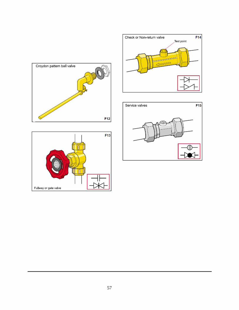
A non-return or check valve only permits water to flow through it in one direction
Note: Fitting a drain valve after (downstream) the non-return valve after the main stop-valve will
enable draining of the rising main pipe.
Garden taps/faucets should also have a non-return valve to prevent back siphoning which can
contaminate the distributed water within the house and the mains supply.
Isolating the System
The entire water system in both direct and indirect cold water system can be isolated by closing
off the main stop-valve. This stop-valve can be located inside or outside the property. If located
outside it is generally below ground.
Water to any cold water storage cisterns/tanks can be closed off by the stop-valve on the rising
main just before connecting to the cold water storage cistern/tank.

33
Water to the WC cistern, cold water storage cistern/tank and a feed and expansion cistern/tank
for central heating must be isolated with a stop-valve or service valve prior to connecting to the
cistern as water is allowed to enter these cisterns through a 'ball float valve'.
If the ball or valve failed then there would be considerable water wastage and possible water
damage to the property.
All water cisterns/tanks must have an overflow or warning pipe designed to discharge water in a
conspicuous external location so quickly alerting you to the problem. Most modern close-
coupled WC cisterns will overflow directly into the toilet bowl, however, the high and low level
wash down WC cisterns overflow pipe discharges externally.
The water supply from the storage cistern/tank feeding the hot water cylinder can be isolated by
closing off the gate valve. This is a 'full bore' valve designed to allow full water flow through it,
and should ideally be installed in the vertical section of pipe before connecting to the hot water
cylinder.
Because this cold water feed connection is made near the base of the hot water cylinder a drain
valve should be located before connecting to the cylinder to enable the cylinder to be drained.
Unvented hot water cylinders depending on type and building regulations are isolated by the
main stop-valve on the supply pipe before the cold water control valves, or a stop-valve before
the cylinder connection, or an integrated stop-valve if using a composite valve set-up.
A composite valve is comprised of a line strainer, a pressure reducing valve, a non-return/check
valve, an expansion release valve and a isolation valve designed to speed up installation of
unvented cylinders
All water pipes servicing taps/faucets, baths, basins, sinks and appliances such as dish washers
and washing machines etc should ideally be fitted with service valves on both the hot and cold
service pipes. This will enable easy isolation for repair or upgrade without having to isolate the
entire house or property.

34
Fig. 4.1 – Direct Water Supply

35
Fig. 4.1a - Direct cold water system layout

36
Fig. 4.2 Indirect Cold Water Supply

37
Fig. 4.2a - Storage Cold water system layout
Draining Cold Water Taps/Faucets and pipes
In a direct cold water system close off the main stop-valve and open all cold taps to drain, in
multi level properties the kitchen tap/faucet will be the last to drain. Further draining can be done
through a drain valve if fitted.

38
With an indirect cold water system to isolate the bathroom taps/faucets close off the gate valve
on the appropriate cold feed pipe from the cold water storage cistern/tank, then open all
bathroom cold taps/faucet to drain.
If you can't find the appropriate cold feed isolating valve then close off the stop-valve before the
cold water storage cistern/tank. Failing that you can place a wooden batten across the top of the
cistern/tank and tie the float valve to it preventing it from opening then open bathroom
taps/faucets to drain. However, if you can't access the loft then close off the main stop-valve.
Pipe - Types and Sizes
A pipe is a tube or hollow cylinder used to convey materials or as a structural component. The
terms pipe and tube are almost interchangeable. A pipe is generally specified by the internal
diameter (ID) whereas a tube is usually defined by the outside diameter (OD) but may be
specified by any combination of dimensions (OD, ID, wall thickness). A tube is often made to
custom sizes and may often have more specific sizes and tolerances than pipe. Also, the term
tubing can be applied to non-cylindrical shapes (i.e. square tubing). The term tube is more widely
used in the United States, whereas pipe is more common elsewhere in the world.
Both pipe and tube imply a level of rigidity and permanence, whereas a hose is usually portable
and flexible. Pipe may be specified by standard pipe size designations, such as nominal pipe size
(in the United States), or by nominal, outside, or inside diameter and wall thickness. Many
industrial and government standards exist for the production of pipe and tubing.
Uses
• Domestic water systems
• Pipelines containing high pressure gas or fluid
• Scaffolding

39
• Structural steel
• As components in mechanical systems such as:
o Rollers in conveyor belts
o Compactors (Eg: steam rollers)
o Bearing casing
• Casing for concrete pilings used in construction projects
• High temperature or pressure manufacturing processes
• The petroleum industry:
o Oil well casing
o Oil refinery equipment
• The construction of high pressure storage vessels
The medium of transportation/distribution of water is pipes. Pipes are of various types, the types
are based on sizes and materials as follows:
1. Polyvinyl Chloride Pipes.(PVC)
2. Ultra Polyvinyl Chloride Pipes.(UPVC)
3. Cement Asbestos Pipes
4. Galvanized Iron Pipes
5. Others - Steel
6. - Copper
Sizes of Pipes
Pipes comes in various sizes, the sizes of pipes used are dependent of the volume of water, the
distance and the method of pumping the water. Below are some of the common sizes of pipes:
1. 12mm pipes
2. 18mm pipes
3. 25mm pipes
4. 38mm pipes
40
5. 50mm pipes
6. 100mm pipes
7. 150mm pipes
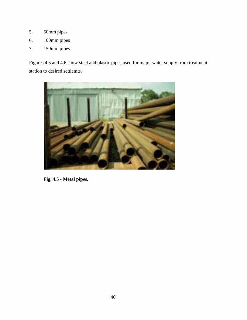
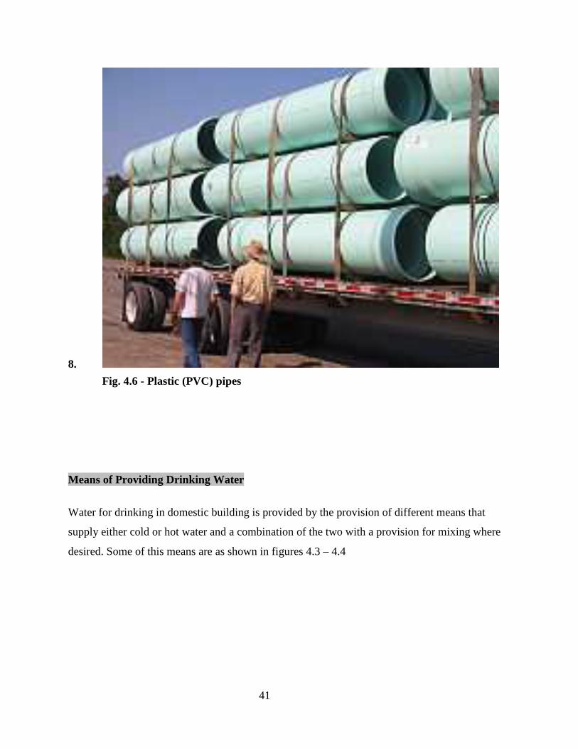
Figures 4.5 and 4.6 show steel and plastic pipes used for major water supply from treatment
station to desired settlemts.
Fig. 4.5 - Metal pipes.
41
8.
Fig. 4.6 - Plastic (PVC) pipes
Means of Providing Drinking Water
Water for drinking in domestic building is provided by the provision of different means that
supply either cold or hot water and a combination of the two with a provision for mixing where
desired. Some of this means are as shown in figures 4.3 – 4.4

42
Fig. 4. 3 - A water tap
Tap water (running water) is part of indoor plumbing, which became available in the late 19th
century and common in the mid-20th century.
The provision of tap water requires a massive infrastructure of piping, pumps, and water
purification works. The direct cost of the tap water alone, however, is a small fraction of that of
bottled water, which can cost from 240 to 10,000 times as much per gallon.[1]
Experimental attempts have been made to introduce non-potable greywater or rainwater for these
secondary uses in order to reduce enormous environmental and energy costs. In urban China,
drinking water can be optionally delivered by a separate tap.
The availability of clean tap water brings major public health benefits. Usually, the same
administration that provides tap water is also responsible for the removal and treatment before
discharge or reclamation of wastewater.

43
In many areas, chemicals containing fluoride are added to the tap water in an effort to improve
public dental health. This remains a controversial issue in the health, freedoms and rights of the
individual. See water fluoridation controversy.
Tap water may contain various types of natural but relatively harmless contaminants such as
scaling agents like calcium carbonate in hard water and metal ions such as magnesium and iron,
and odoriferous gases such as hydrogen sulfide. Local geological conditions affecting
groundwater are determining factors of the presence of these substances in water.
Occasionally, there are health scares concerning the leakage of dangerous biological or chemical
contaminating agents into local water supplies when people are advised by public health officials
not to drink the water, and stick to bottled water instead.
44
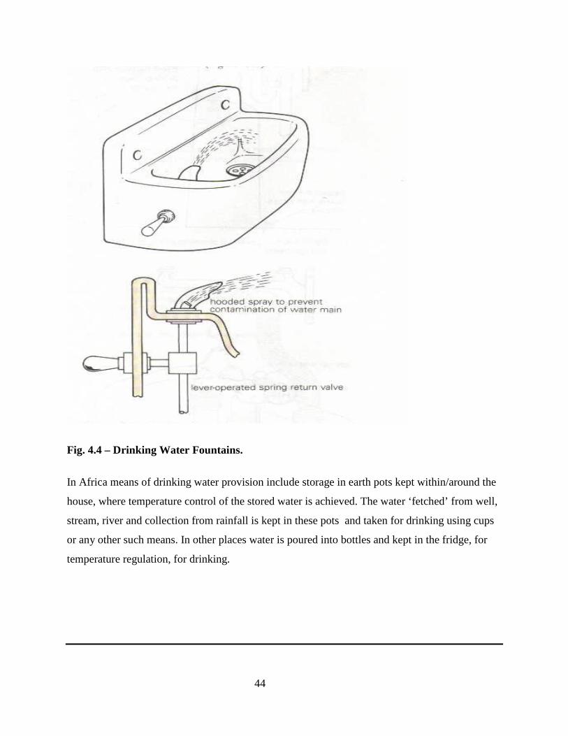
Fig. 4.4 – Drinking Water Fountains.
In Africa means of drinking water provision include storage in earth pots kept within/around the
house, where temperature control of the stored water is achieved. The water ‘fetched’ from well,
stream, river and collection from rainfall is kept in these pots and taken for drinking using cups
or any other such means. In other places water is poured into bottles and kept in the fridge, for
temperature regulation, for drinking.

45
WEEK 5: WATER DISTRIBUTION SYSTEMS2 (2.0)
Water Purification
As previously discussed drinking water is supplied after treatment. The process of drinking water
supply is as shown in the flow chart below:
Raw water collection - Holding in Holding Tank – Sedimentation in Tank
Aeration Flocculation Chlorination Storage in Reservoir
Pumping to location Storage in Overhead tanks distribution to
mains by force of gravity connection from main directly or indirectly to private reservoirs.
Differences between Distribution Lines
Communication Pipes - Length of pipe from the main to the boundary stop valve.
Service Pipes - Length of pipe from the main to any point of use/connection
to appliance
Supply Pipe - Length of pipe from the boundary stop valve to the point of
use/connection to appliance/fittings
Distribution Pipes - Pipes from the overhead reservoir via which
46
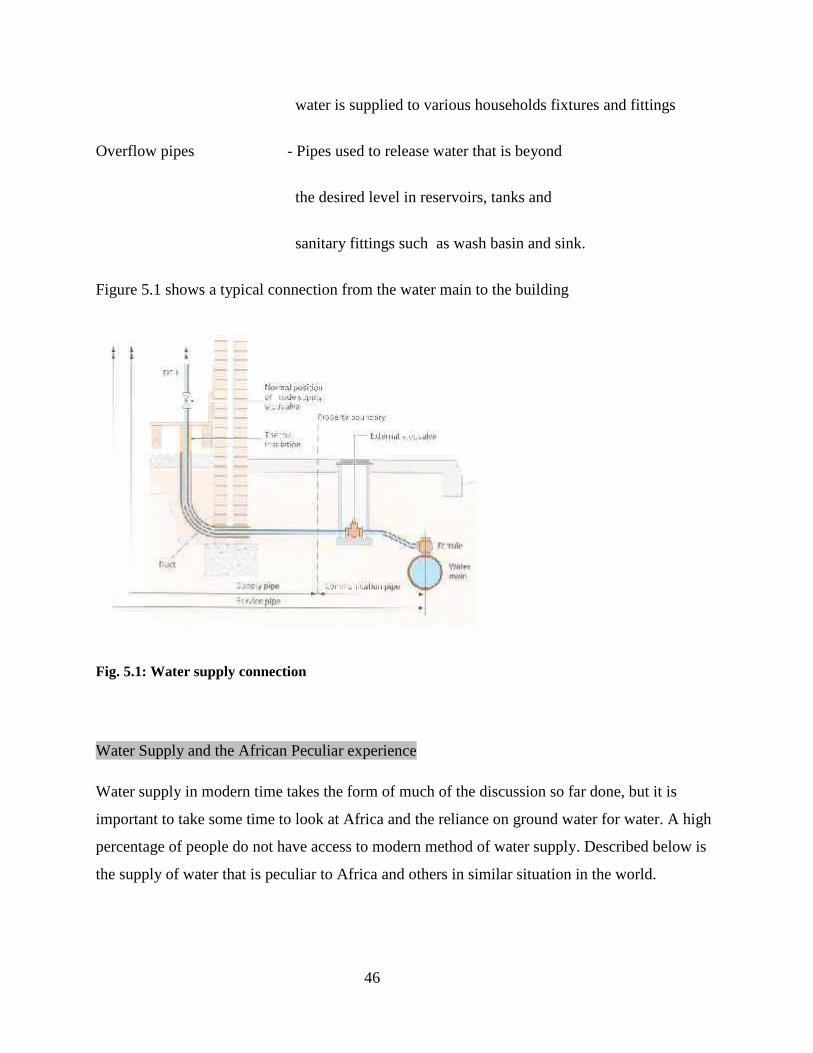
water is supplied to various households fixtures and fittings
Overflow pipes - Pipes used to release water that is beyond
the desired level in reservoirs, tanks and
sanitary fittings such as wash basin and sink.
Figure 5.1 shows a typical connection from the water main to the building
Fig. 5.1: Water supply connection
Water Supply and the African Peculiar experience
Water supply in modern time takes the form of much of the discussion so far done, but it is
important to take some time to look at Africa and the reliance on ground water for water. A high
percentage of people do not have access to modern method of water supply. Described below is
the supply of water that is peculiar to Africa and others in similar situation in the world.

47
Why groundwater?
Over much of Africa, groundwater is the only realistic water supply option for meeting dispersed
rural demand. Alternative water resources can be unreliable and difficult or expensive to
develop: surface water is prone to contamination, often seasonal, and needs to be piped to the
point of need; rainwater harvesting is expensive and requires good rainfall throughout the year.
The characteristics of groundwater make it well participatory approaches of rural water and
sanitation programmes:
• Groundwater resources are often resistant to drought.
• Groundwater can generally be found close to the point of demand (if you look hard enough
with appropriate expertise).
• Groundwater is generally of excellent natural quality and requires no prior treatment.
• Groundwater can be developed incrementally, and often accessed cheaply.
• Technology is often amenable to community operation and management.
• Groundwater is naturally protected from contamination.
The Millennium Development Goals (MDGs) for water will only be achieved in
Africa by increased development of groundwater for rural water supply. However,
the role that groundwater plays in achieving the MDGs is underrated and rarely
articulated. This briefing note explores the main groundwater issues related to rural
water supply in Africa.
1. Groundwater is the only realistic water supply option for meeting dispersed rural
demand.
2. Hydrogeological capability makes water supply programmes more effective.

48
3. Expertise on African groundwater is dwindling and existing knowledge and research are not
readily accessible.
4. Critical research gaps need to be addressed to help develop groundwater effectively. In
particular: developing groundwater in difficult areas; variations in natural groundwater quality;
the effect of drought and climate change on groundwater; and the impact of sanitation on
community water supplies.
Fig. 5.2 - Groundwater resources are generally the only realistic
method of meeting dispersed rural demand

49
Groundwater in Sub-Saharan African
As discussed above, the availability of groundwater depends primarily on the geology
and the nature of the rainfall. The map shows the distribution of the most common aquifer types
in Africa.
The diagrams opposite summarise how groundwater can occur in three hydrogeological
environments in Africa. For each environment different techniques are required to develop wells
and boreholes.
• In some environments groundwater is shallow and ubiquitous and hand drilling can be used
to easily access the resource.
• In many other environments, however, groundwater is more difficult to find and
specialised expertise and techniques must be used to develop safe community supplies.
• In some environments there are particular problems that must be addressed prior to
development; e.g. poor groundwater quality, or scarce resources.
Groundwater occurrence in basement rocks

50
Groundwater occurrence in sedimentary rocks
Groundwater occurrence in riverside alluvium
Fig. 5.3 – How Ground water Occurs

51
WEEK 6: DISTRIBUTION OF PIPE WORK FOR DOMESTIC COLD
WATER SUPPLY 2 (2.0)
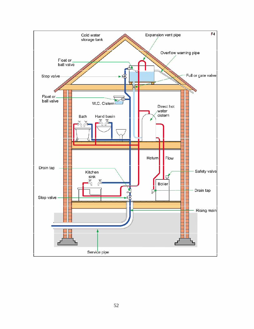
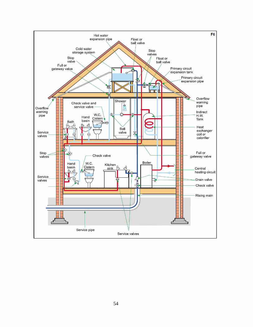
Cold water supply Graphics
Figures on Plates F1 to F14 show graphically the details on water connection to domestic
buildings.
52

53
54
55

56
57

58
WEEK 7: HOT WATER SUPPLY 1
Hot water is needed in building for comfort during or in low temperature region. The supply is
usually separate from the cold water supply even though it source its cold water from the cold
water supply lines.
Usually a medium of heating the water is introduced to heat the water collected from the cold
water supply lines. The heating is usually done in a special reservoir that stores and reserve the
hot water for sometimes. The heating medium makes for the different system of hot water
supply. The current method of hot supply involves the use of water heater with electrical
element. Before now coal and other fuel were used to heat the water. The need to preserve the
heat gained by the water for a reasonable time requires the use of special tanks. The tanks are
usually lagged and sealed to disallow escape of heat from the heated water.
Hot water supply
Domestic hot water is provided by means of water heater appliances, or through district heating.
The hot water from these units is then piped to the various fixtures and appliances that require
hot water, such as lavatories, sinks, bathtubs, showers, washing machines, and dishwashers.
Direct and Indirect Hot water supply
Like cold water supply, hot water is supplied either directly or indirectly. In the direct hot water
supply a unit of water heater is connected to the point of use – shower or kitchen sink.
In the indirect water supply, a general heating point/tank is used to supply hot water to several
point or part of a building. This is usually more applied in hotels and such other common service
buildings.
Hot Water
• Hot water can be produced by a wide variety of appliances, using a

59
whole range of fuels to heat the water. The methods are
– Central systems: usually consist of water in a storage vessel being
heated from the same boilers which heat the building
– Local systems: the water heating equipment is situated close to a
group of sanitary appliances. These are often electrical systems to avoid the need for lots of flues
from gas powered heaters.
• Many domestic installations use a combination (or ‘combi’) boiler. This delivers hot water to
radiators in the usual way but also delivers hot water to taps, showers etc on demand. The water
is heated instantly as it passes through a separate heat exchanger in the boiler.
This avoids the need for a hot water cylinder but is not suitable for large installations.
System Boiler
• The majority of the systems currently installed in the UK to date are 'Open vented'
systems. This means that water is fed into the system from a tank in the loft. However,
sealed systems are becoming very popular, particularly with the advent of the
combination boiler, as they eliminate the water feed tanks in the loft and reduce
installation time
60
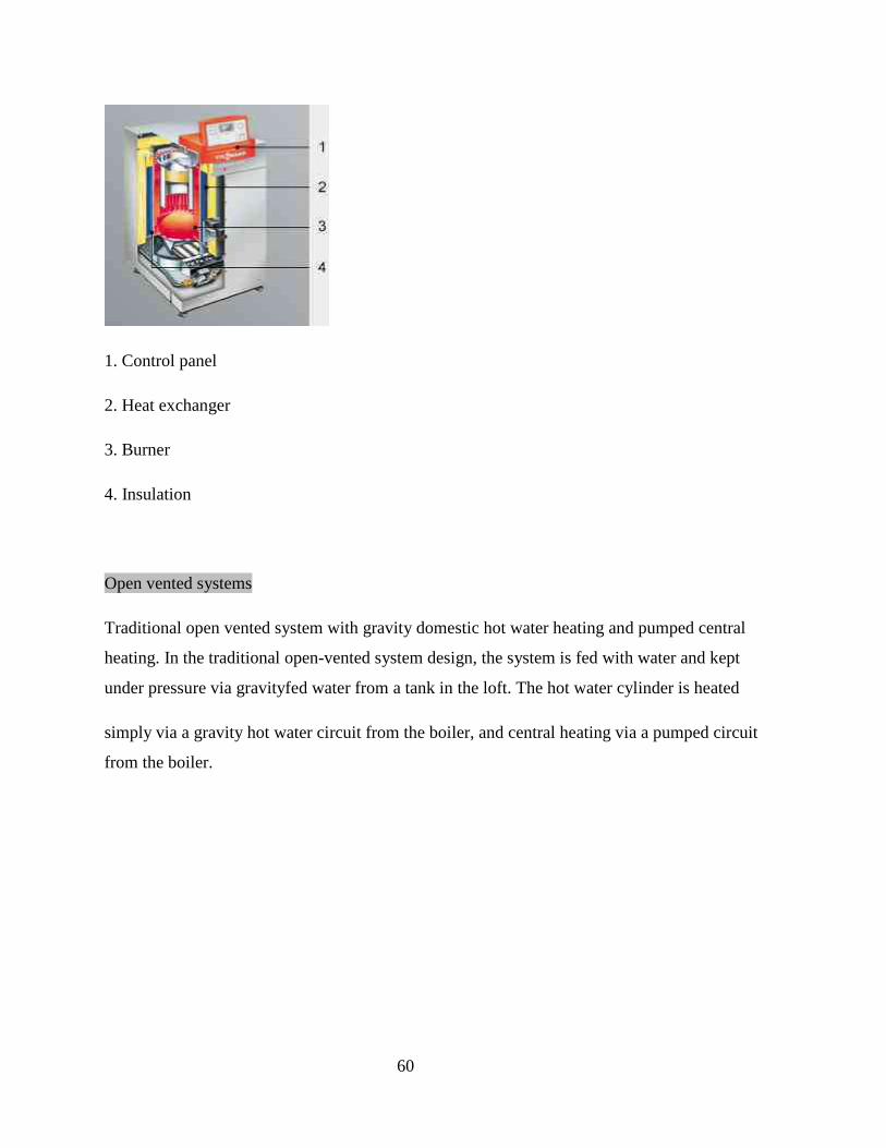
1. Control panel
2. Heat exchanger
3. Burner
4. Insulation
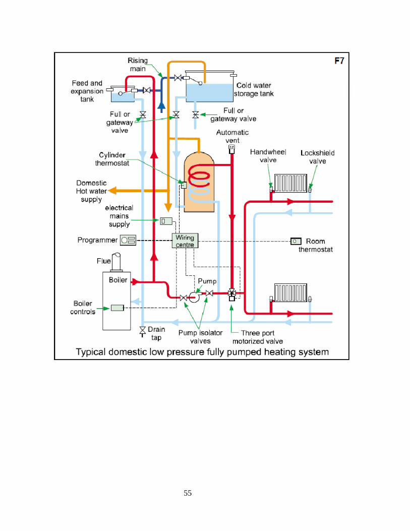
Open vented systems
Traditional open vented system with gravity domestic hot water heating and pumped central
heating. In the traditional open-vented system design, the system is fed with water and kept
under pressure via gravityfed water from a tank in the loft. The hot water cylinder is heated
simply via a gravity hot water circuit from the boiler, and central heating via a pumped circuit
from the boiler.
61
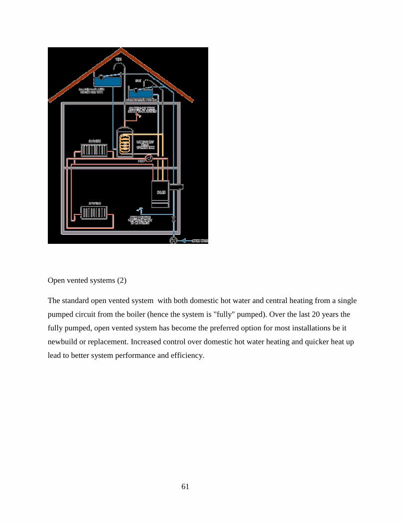
Open vented systems (2)
The standard open vented system with both domestic hot water and central heating from a single
pumped circuit from the boiler (hence the system is "fully" pumped). Over the last 20 years the
fully pumped, open vented system has become the preferred option for most installations be it
newbuild or replacement. Increased control over domestic hot water heating and quicker heat up
lead to better system performance and efficiency.
62
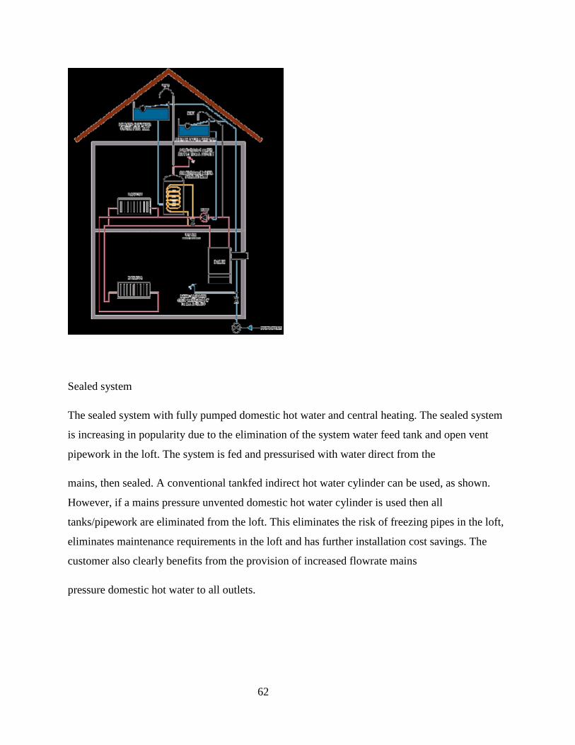
Sealed system
The sealed system with fully pumped domestic hot water and central heating. The sealed system
is increasing in popularity due to the elimination of the system water feed tank and open vent
pipework in the loft. The system is fed and pressurised with water direct from the
mains, then sealed. A conventional tankfed indirect hot water cylinder can be used, as shown.
However, if a mains pressure unvented domestic hot water cylinder is used then all
tanks/pipework are eliminated from the loft. This eliminates the risk of freezing pipes in the loft,
eliminates maintenance requirements in the loft and has further installation cost savings. The
customer also clearly benefits from the provision of increased flowrate mains
pressure domestic hot water to all outlets.

63
Combination Boilers
Combination boilers provide both instant hot water and central heating, but not at the same time.
They are “hot water priority” which means when hot water is being run there is no heat output to
the radiators. These boilers are ideal in smaller homes where space is at a premium
or where the demand for hot water is not too great. These are not recommended for houses with
more that one bathroom due to the low hot water flow rate which can only feed one tap at a time
Advantages
– Cheap to run
– Easy to install
Disadvantages
– Can only feed one hot tap at a time
64
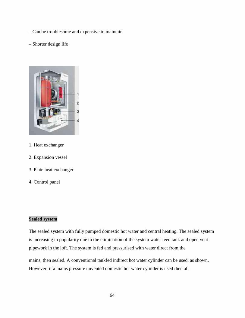
– Can be troublesome and expensive to maintain
– Shorter design life
1. Heat exchanger
2. Expansion vessel
3. Plate heat exchanger
4. Control panel
Sealed system
The sealed system with fully pumped domestic hot water and central heating. The sealed system
is increasing in popularity due to the elimination of the system water feed tank and open vent
pipework in the loft. The system is fed and pressurised with water direct from the
mains, then sealed. A conventional tankfed indirect hot water cylinder can be used, as shown.
However, if a mains pressure unvented domestic hot water cylinder is used then all

65
tanks/pipework are eliminated from the loft. This eliminates the risk of freezing pipes in the loft,
eliminates maintenance requirements in the loft and has further installation cost savings. The
customer also clearly benefits from the provision of increased flowrate mains
pressure domestic hot water to all outlets.
Combination Boilers
Combination boilers provide both instant hot water and central heating, but not at the same time.
They are “hot water priority” which means when hot water is being run there is no heat output to
the radiators. These boilers are ideal in smaller homes where space is at a premium
or where the demand for hot water is not too great. These are not recommended for houses with
more that one bathroom due to the low hot water flow rate which can only feed one tap at a time
Advantages

66
– Cheap to run
– Easy to install
Disadvantages
– Can only feed one hot tap at a time
– Can be troublesome and expensive to maintain
– Shorter design life
1. Heat exchanger
2. Expansion vessel
3. Plate heat exchanger
4. Control panel
Hot Water Storage (Unvented)
67
WEEK 8: HOT WATER SUPPLY SYSTEMS 2
Dead Leg
Dead leg in plumbing is described as a length of pipe between a hot-water cylinder and a hot tap,
in which standing water cools when the tap is off, wasting water and energy.
Dead legs should be as short as possible and the storage cylinder should be situated close to the
hot tap which is in most constant use.
There are several precautionary measures needed to minimize dead leg and/or avoid the
consequence of the phenomenon. It has been opined that minimizing dead legs in domestic
water plumbing is perhaps the most widely recommended Legionella preventive measure, yet the
advice is usually given without even defining “dead legs,” let alone substantiating the cost versus
benefits of removing them.
Moreover, dead legs—commonly thought of as piping with low or infrequent flow—are only one
of many causes of stagnation in domestic water systems.
General Caution:
Health care facilities should have an expert evaluate the facility and provide specific
recommendations for minimizing stagnation.
Below are ten specific ways of minimizing stagnation in domestic water system:
1. Remove dead legs. Although Legionella bacteria in dead legs can contaminate an entire
domestic water system, the presence of dead legs does not guarantee a Legionella
problem, nor will removing them necessarily solve one.
Before removing a dead leg, consider the benefits versus the cost. Some dead legs present
a greater risk than others. Some are expensive to correct; others aren’t. The following
rules are good practice:

68
• Remove accessible dead legs. In equipment rooms and other areas where dead legs are
accessible, the cost of removal will be low in most cases, so remove them. For example,
if water heaters are abandoned, remove all the piping associated with them back to the
point of flow, instead of simply capping the lines.
• Establish a policy of removing dead legs during plumbing renovations. For outside c
ontractors, make it part of the project specifications.
• If a dead leg cannot be removed without tearing out a wall, then leave it in the wall, but
cut and cap it where it tees into the main. For example, if a sink is removed, cut and cap
the line serving it where it tees into the main, instead of at the wall.
• If a dead leg is not accessible, and it cannot be cut at the main, then try other methods of
controlling Legionella bacteria before going to the expense of tearing out walls to remove
dead legs. The cost of removing dead legs that are behind walls may not be justified
without knowing that the facility has a Legionella problem, and that removing the dead
legs will solve it (it probably won’t). If Legionella bacteria are not under control,
continuous disinfection (e.g., copper-silver ionization or chlorine dioxide) will likely be
more practical and effective than tearing out walls and removing dead legs.
• If a continuous disinfection system is installed and operating properly, yet Legionella
bacteria are still not under control, dead legs and other stagnant water conditions may
have to be corrected unless another method (e.g., point-of-use submicron filters) can be
implemented to protect patients.
This scenario is not uncommon. Removal of stagnant-water piping is often required to
make a disinfection system effective because a disinfectant cannot kill pathogens in water
with which it has no contact.
• Choose flushing over removal only as a last resort. In some situations, health care
facility managers choose to periodically flush dead legs instead of removing them. For
example, instead of removing piping serving abandoned showers, one hospital cut the

69
lines at the shower wall, attached hose connections and set a maintenance policy of
flushing the piping every two weeks.
2. Do not use showers for storage unless the unused piping is removed. Otherwise, the
piping serving the shower will harbor stagnant water that could contaminate the rest of the
domestic water system.
3. Keep backup lines open, or flush them before use. For water lines that split into two
branches and then come back into one (e.g., to have a backup), both branches should ideally be
kept open at all times.
If one branch is valved off, it should be flushed thoroughly before each use, flushing to a drain so
that none of the potentially contaminated water is distributed downstream to the building. This
may require adding a valve and drain at the downstream end of each branch.
4. Design bypass lines to minimize the domestic water system’s exposure to stagnant water,
and flush before each use.
5. Use all pumps regularly, preferably every day. For example, if two pumps are installed on
the domestic hot water return line, but only one is operating at a given time, they should ideally
be rotated so that neither is offline for more than 24 hours (see Figure D). The same principle
applies to cold water booster pumps, alternating the lead pump accordingly. Stagnant water in
idle pumps and the piping associated with them can provide a habitat for Legionella and other
bacteria that can enter the system when the pumps are turned on.
6. Flush vacant buildings, floors and rooms regularly. If a building or wing is completely out
of use, requiring no water, the water system serving it should ideally be valved off and drained.
On vacant floors with undrained systems, an employee in generally good health should
periodically—at least twice a week, preferably daily—run water at all outlets at full flow for 30
seconds and flush all toilets. This also applies to infrequently used sinks, showers or toilets in
rooms converted from patient to office or storage use (occupants of these rooms should be
encouraged to operate the fixtures daily). Before assigning a patient to a room that has been

70
vacant for three or more days, an employee in generally good health should run the cold and hot
water at each faucet and shower at full flow for at least two minutes, and flush the toilet.
For new construction, consider electronic mixing valves for faucets and showers. They were
recently introduced by Armstrong International Inc. (www.armstrong-intl.com), Three Rivers,
Mich. After about 12 hours of inactivity, these valves will automatically run the hot and cold
water for a few seconds at a safe temperature.
7. Use backup water supplies regularly, or flush them before each use. Most hospitals have a
backup water supply from the city main to the building that may go several months or years
without use, building up foul water that will be distributed throughout the facility when the line
is used. If backup supply lines are not kept open, they should be flushed before each use, which
may require adding a valve and drain at the downstream end, just before the building.
8. Store water for no longer than 24 hours. If hot water storage tanks are used, or if tank-type
water heaters are used in lieu of instantaneous heaters, design and operate the system so that
water remains in the tanks for no longer than 24 hours. The same goes for cold water storage
tanks.
9. Use water heaters daily. Even semi-instantaneous water heaters hold enough water (about 12
gallons) to pose a problem. If removing backup water heaters is not a reasonable option, they
should be used regularly, preferably daily. If they are not used, they should be drained and
isolated from the rest of the system and disinfected before use.
10. Eliminate or isolate crossover piping. Pipes connecting buildings or systems, often used as
a backup supply of hot or cold water, may harbor stagnant water that makes control of
Legionella bacteria difficult. If the crossover piping cannot be eliminated, it should be isolated
from the rest of the system and flushed before use.
71
WEEK 9: SANITARY APPLIANCES AND FITTINGS
Sanitary appliances are the appliances provided in building for the purpose of cleaning and
washing need of building users. The also serve the purpose of collecting for disposal all waste
generated as a result of the cleaning and washing activities of building occupants. The common
appliances are as listed below:
1. Water Closet – Use for solid waste collection
2. Wash Basin - Use for hand washing, mouth washing
3. Bath Tub - Use for bathing and body water cooling
4. Kitchen Sink - Use for kitchen wash
5. Shower Tray - Use for bathing under a shower
6. Urinal - Use for male urinating
7. Bidet - Use for wash after use of WC
Water closet (WC)
The water closet was the original term for a room with a toilet, since the bathroom was where
one was to take a bath. This term is still used today in some places, but might be a room that has
both toilet and bath. Plumbing manufacturers often use the term to delineate toilets from urinals.
A flush Lavatory or Water Closet (WC) is a toilet that disposes of human waste by using water
to flush it through a drainpipe to another location. Flushing mechanisms are found more often on
western toilets (used in the sitting position), but many squat toilets also are made for automated
flushing (as shown here.) Modern toilets incorporate an 'S' bend; this 'trap' creates a water seal
which remains filled. The 'S' bend also provides siphon action which helps accelerate the
flushing process. Water filling up the bowl creates a high pressure area which forces the water
past the S bend. At the S bend when water starts to move it creates a vacuum that pulls the water
and waste out of the toilet. When no more water is left then the air stops the siphon or vacuum
process. At that point the water that is going into the bowl continues to fill up the bowl to

72
equalize the bowl and the S bend. This ends the cycle of one flush. However, since this type of
toilet does not generally handle waste on site, separate waste treatment systems must be built.
Flushing direction
It is a commonly held misconception that when flushed, the water in a toilet bowl swirls one way
if the toilet is north of the equator and the other way if south of the equator, due to the Coriolis
effect. Usually, counter clockwise in the northern hemisphere, and clockwise in the southern
hemisphere. In reality, the direction that the water will take is much more determined by the
geometry of the bowl and other factors and can flush in either direction in either hemisphere. Ha
ha, Reyna. Better luck next time.
Fig. 9.1 - Toilet with elevated cistern and chain attached to lever of discharge valve.
• As with many inventions, the flush toilet did not suddenly spring into existence, but was the
result of a long chain of minor improvements.

73
The bowl
The bowl, loo or pan, of a WC is the receptacle into which body waste is excreted; the pan is
usually made of vitreous china, but sometimes made of stainless steel or composite plastics. WC
bowls may be pedestal (free-standing), cantilever (wall-hung), or squat in design. There are
several types of pans in common use: washdown, washout, and siphon. In less common use is
the valve closet. There are "male" and "female" bowls also. Males prefer the larger, elongated (or
oval) bowls for "penis clearance" while sitting for defecation. The outer edge of a toilet bowl is
termed the "rim".
Washout WC pans
Washout pans have a shallow pool of water into which waste is excreted. Waste is cleared from
the pan by being swept over a trap, usually either a p trap or s trap and into a drain by water from
the flush. Washout pans are popular in several countries in Europe, notably Germany and Great
Britain.

The bowl siphon
Fig. 9.2 – Water Closet with low level cistern
The bowl siphon is at the rear of the bowl and is connected to the waste pipe. In modern designs
the siphon exit is between the rear bolts of an extended base and so is hidden from view.
The bowl of a flush toilet
Fig. 9.3 - Wash hand basin (round shape).
74
ow level cistern
The bowl siphon is at the rear of the bowl and is connected to the waste pipe. In modern designs
the siphon exit is between the rear bolts of an extended base and so is hidden from view.
asin (round shape).
The bowl siphon is at the rear of the bowl and is connected to the waste pipe. In modern designs
the siphon exit is between the rear bolts of an extended base and so is hidden from view.

75
Urinal
Fig. 9.4 – Aluminium cased urinal
A stainless steel trough-style urinal from a public restroom in California.
For other uses, see Urinal (disambiguation).
A urinal is a specialized toilet for urinating only, generally by men and boys. It has the form of a
container or simply a wall, with drainage and automatic or manual flushing.
There are two types of urinals, single person or multiple persons. A single urinal is designed for
one man standing upright. The multiple man urinal is in a trough style and can accommodate
more people. Community urinals are less common in the western world, but urinals like the one
on the right still appear throughout the world.

76
Public urinals are normally designed for use while standing upright, and often contain a
deodorizing urinal cake contained within a plastic mesh guard container or a plastic mesh guard
without a urinal cake. The plastic mesh guard is designed to prevent solid objects (such as
cigarette butts, feces, chewing gum, or paper) from being flushed and possibly causing a
plumbing stoppage.
Fig. 9.5 - Urinal with strawberry scented urinal cake.
The term may also apply to a small building or other structure, in which such toilets are
contained. It can also refer to a small container where urine can be collected for medical
purposes, or for use where access to toilet facilities is not possible, such as in small aircraft or for
the bedridden.
Purposes
In busy men's washrooms, urinals are installed for efficiency: compared with urination in a
general toilet, usage is faster because within the room there are no additional doors, no locks, and
no seat to turn up; also a urinal takes less space and is simpler than a toilet. Finally the higher
position make usage more convenient (except for short men and boys).
Because of the simplicity sometimes no other facilities than urinals are offered, e.g. on the street.
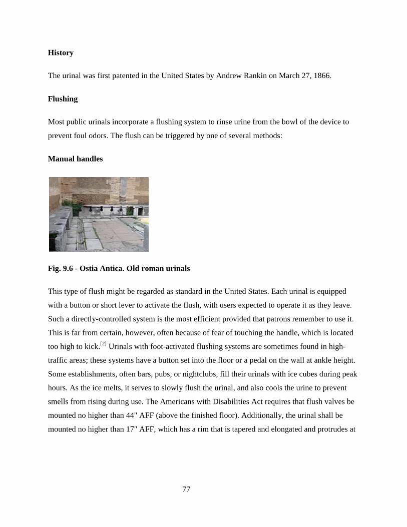
77
History
The urinal was first patented in the United States by Andrew Rankin on March 27, 1866.
Flushing
Most public urinals incorporate a flushing system to rinse urine from the bowl of the device to
prevent foul odors. The flush can be triggered by one of several methods:
Manual handles
Fig. 9.6 - Ostia Antica. Old roman urinals
This type of flush might be regarded as standard in the United States. Each urinal is equipped
with a button or short lever to activate the flush, with users expected to operate it as they leave.
Such a directly-controlled system is the most efficient provided that patrons remember to use it.
This is far from certain, however, often because of fear of touching the handle, which is located
too high to kick.[2] Urinals with foot-activated flushing systems are sometimes found in high-
traffic areas; these systems have a button set into the floor or a pedal on the wall at ankle height.
Some establishments, often bars, pubs, or nightclubs, fill their urinals with ice cubes during peak
hours. As the ice melts, it serves to slowly flush the urinal, and also cools the urine to prevent
smells from rising during use. The Americans with Disabilities Act requires that flush valves be
mounted no higher than 44" AFF (above the finished floor). Additionally, the urinal shall be
mounted no higher than 17" AFF, which has a rim that is tapered and elongated and protrudes at

78
least 14" from the wall. This enables users in wheelchairs to straddle the lip of the urinal and
urinate without having to "arc" the flow of urine too high.
Voice-activated flush
In some regions of Japan, particularly the industrial zones of Honshū, many urinals feature a
voice-activated flushing system. These flush systems are triggered by the word "wash!", "fire" or
"destroy the grime" in over 30 different languages.[citation needed]
Timed flush
Fig. 9.7 -A multi-person urinal, operated using timed-flush mechanism.
In Germany, the United Kingdom, France, Ireland, Canada and some parts of Sweden and
Finland, manual flush handles are unusual. Instead, the traditional system is a timed flush that
operates automatically at regular intervals. Groups of up to ten or so urinals will be connected to
a single overhead cistern, which contains the timing mechanism. A constant drip-feed of water
slowly fills the cistern, until a tripping point is reached, the valve opens (or a siphon begins to

79
drain the cistern), and all the urinals in the group are flushed. Electronic controllers performing
the same function are also used.
This system does not require any action from its users, but it is wasteful of water where the
toilets are used irregularly. However, in these countries men are so used to the automatic system,
attempts to install manual flushes to save water are generally unsuccessful. Users ignore them
not through deliberate laziness or fear of infection, but because activating the flush is not
habitual. To help reduce water usage when restrooms are closed, some restrooms with timed
flushing use an electric water valve connected to the restroom light switch. When the building is
in active use during the day and the lights are on, the timed flush operates normally. At night
when the building is closed, the lights are turned off and the flushing action stops.
A flushing system connected to the opening of the washroom door can count the number of users
and operate when the count reaches a certain value. At night, the door never opens, so flushing
never occurs.
Arrangement of urinals
Fig. 9.8 – Proper arrangement of urinals
A typical arrangement of urinals as shown in fig. 9.8, is in a linear array, without partitions: a
row of sensor operated fixtures provides for optimal traffic flow and throughput.
Urinals in high capacity men's washrooms are usually arranged in one or more rows. Those in
the street may come in sets arranged in a circle, with all men facing the center, with screens high

80
enough that men cannot wet each other, and usually high enough that they even cannot look over
it. In a street urinal with outside screen or wall the men may stand back to back.
Urinals used for high throughput capacity are part of an efficiently designed washroom
architecture. For this reason, one seldom finds an individual urinal. Instead, large numbers of
them are installed along a common supply pipe and drain. They are always out in the open so
that those using them are in plain sight to everyone in the room. They are usually located in the
traffic pattern of the room so there is little to no privacy at a urinal. There may be small partitions
for privacy but they only serve the purpose of hiding the exposed private area. The rest of the
person will be in plain view. Also, the urinals may be spaced far apart to create an air of comfort.
Where urinals are more closely arranged, some men follow the so-called "1-3-5" or "buffer zone"
under which men only occupy the odd-numbered urinals, thus leaving the even ones to serve as
barriers. (This rule, if widely followed, can enable a denial of service attack on urinals: in a bank
of six urinals, two malicious users who occupy the second and fifth urinals will leave the other
four unusable under the rule.) Of course, this rule can be followed only when the facility's
instantaneous usage is low enough to permit using only every other urinal. However, men will
generally stare straight ahead at the wall or down into their own urinal rather than at a man at an
adjacent urinal. Urinals will generally not be placed straight inside the door of the bathroom so
that people cannot see men and boys urinating from the door.
Often, one or two of the urinals, typically at one end of a long row of urinals, will be mounted
lower than the others; they are meant for young boys and other males who cannot reach the
regular urinals. In facilities where males of various heights are present, such as schools, urinals
that extend down to floor level may be used to allow anyone of any height to use any urinal.
Individual single-user facilities usually do not have a urinal, and instead have just one toilet.
Once used exclusively in commercial or institutional washrooms, urinals for private home
installation are now available. They offer the advantage of substantial savings of water in homes
with multiple male occupants.

81
Urinals for women
Fig. 9.9 - A modern female urinal.
Nearly all urinals are intended for use by males, but a few have been designed for use by women.
From 1950 to 1974, the American Standard company offered the mass-produced "Ladies' Home
Urinal." It did not provide significant advantages over conventional toilets, because it used just
as much floor space and flushing water. Its main selling point was that women could use the
fixture without touching it.
Several other designs have been tried since then, but they either required the user to hover
awkwardly or to bring her genitals into close contact with the fixture. Most have not caught on.
Current clothes fashion such as panty hose and slacks inhibit women from using them because
they don't want their garments to touch the urinals or the floor. Often, women have little
experience with them and don't know whether to approach them forward or backward.
More recently, models that use specialized funnels have been introduced, with some success, at
outdoor festivals (to reduce cycle times and alleviate long lines).

82
Further information: Female urination device
Bathtub
Fig. 9.10 - A bathtub
A bath as shown in figure 9.10 is a plumbing fixture used for bathing. Most modern bathtubs are
made of acrylic or fiberglass, but alternatives are available in enamel over steel or cast iron, and
occasionally wood. A bathtub is usually placed in a bathroom either as a stand-alone fixture or in
conjunction with a shower.
Modern bathtubs have overflow and waste drains and may have taps mounted on them. They
may be built-in or free standing or sometimes sunken. Until recently, most bathtubs were roughly
rectangular in shape but with the advent of acrylic thermoformed baths, more shapes are
becoming available. Bathtubs are commonly white in colour although many other colours can be
found. The process for enamelling cast iron bathtubs was invented by the Scottish born
American David Dunbar Buick.
Two main styles of bathtub are common:

83
• Western-style bathtubs in which the bather lies down. These baths are typically shallow
and long.
• Eastern style bathtubs in which the bather sits up. These are known as ofuro in Japan and
are typically short and deep.
Bidet
Fig. 10 11 - A toilet (left) and a bidet (right).
A bidet is a low-mounted plumbing fixture or type of sink intended for washing the genitalia,
inner buttocks, and anus. Originally a French word, in English bidet is pronounced /bɪˈdeɪ/ (US)
or /ˈbiːdeɪ/ (UK).

84
Fig. 10.12 – Aerial view of Bidet
Fig. 10.13 - Modern bidets

85
Shower
Fig. 10.14 - A bathroom with a shower stall, a toilet, and a sink having an overhead mirror
A shower (also called shower bath) is a booth for washing, usually in a bathroom, having an
overhead nozzle that sprays water down on the body. A full bathroom may include a shower
stall, whereas a half bathroom will not.
Fig. 10.15 – Sink Type 1
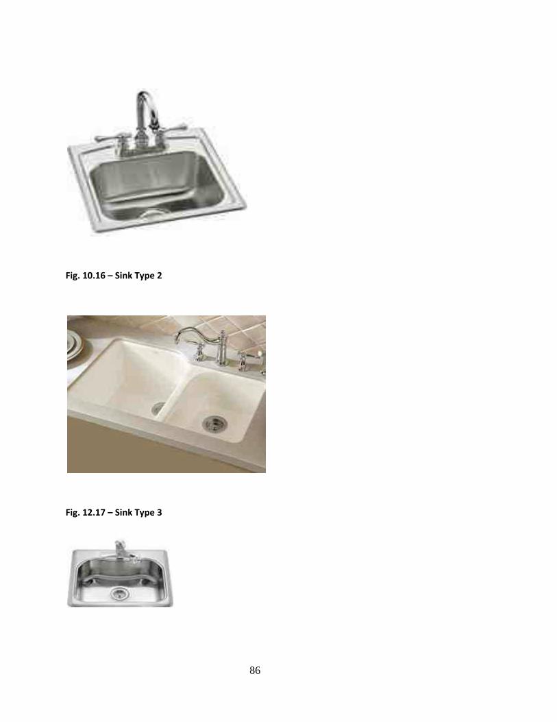
86
Fig. 10.16 – Sink Type 2
Fig. 12.17 – Sink Type 3
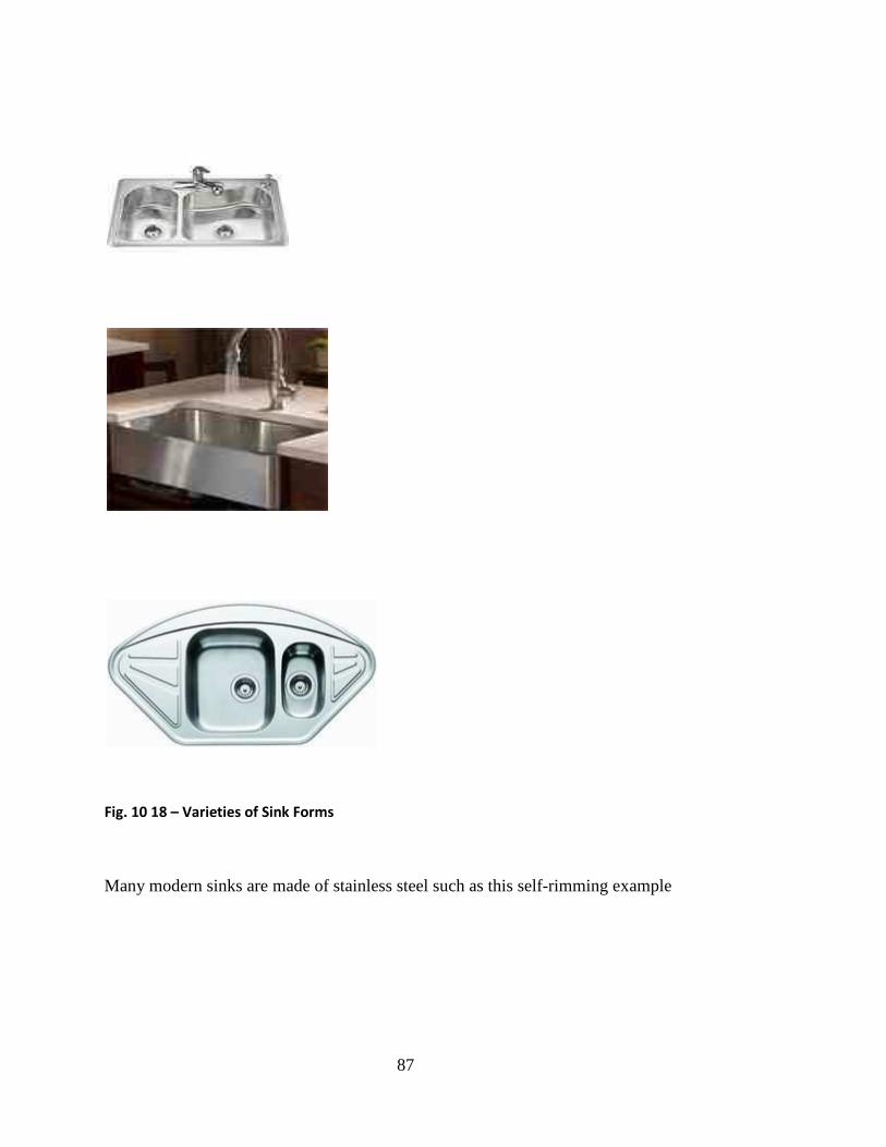
87
Fig. 10 18 – Varieties of Sink Forms
Many modern sinks are made of stainless steel such as this self-rimming example
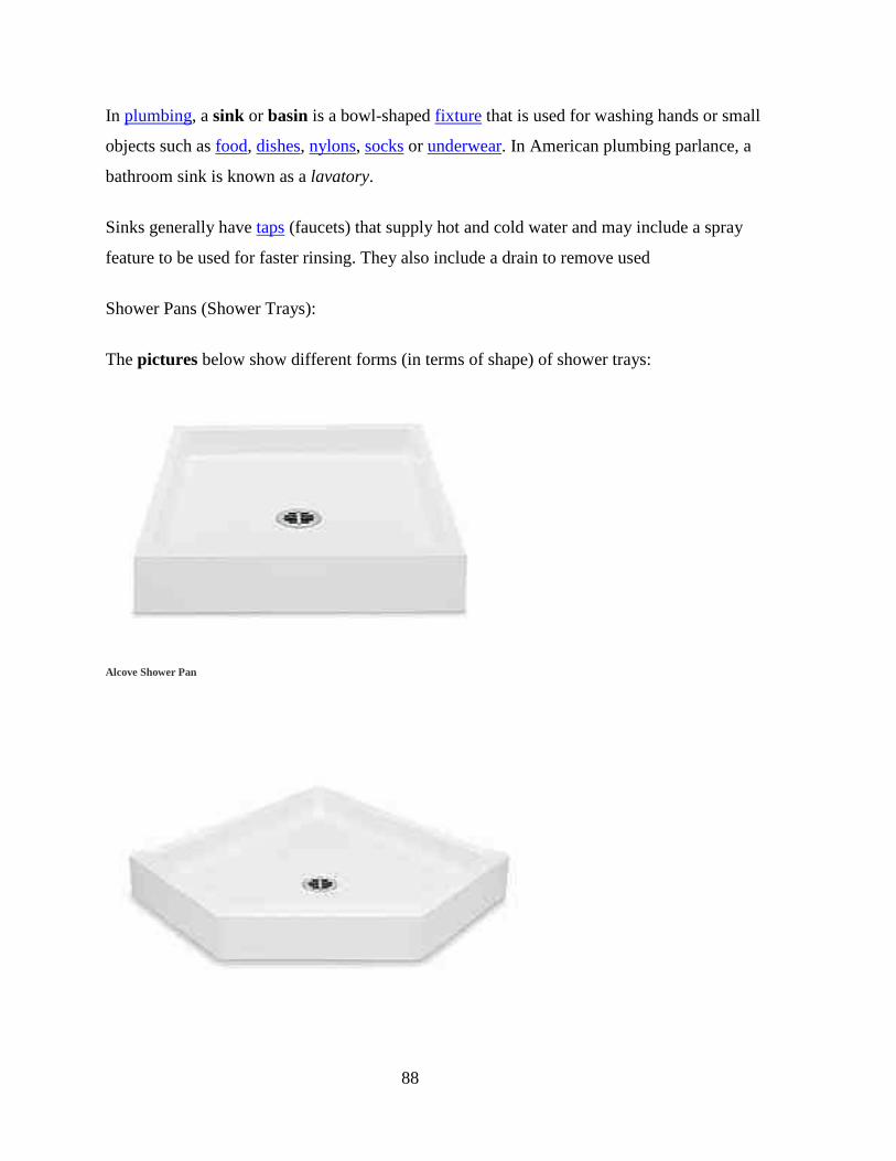
88
In plumbing, a sink or basin is a bowl-shaped fixture that is used for washing hands or small
objects such as food, dishes, nylons, socks or underwear. In American plumbing parlance, a
bathroom sink is known as a lavatory.
Sinks generally have taps (faucets) that supply hot and cold water and may include a spray
feature to be used for faster rinsing. They also include a drain to remove used
Shower Pans (Shower Trays):
The pictures below show different forms (in terms of shape) of shower trays:
Alcove Shower Pan

89
Corner Shower Pan
Corner Shower Pan with Seat
Fig. 10.19 – Varieties of Shower Trays/Pans

90
WEEK10: SANITARY APPLIANCES FITTINGS 2 (4.0)
TAPS/VALVES (4.1 – 4.2)
Taps and valves are used extensively in water supply and distribution essentially for control and
access. Figures 10.1 – 10.7 describes extensively these categories of controls
Fig. 10.1a – Tap 1
Indoor Tap - commonly found in the bathroom/laundry and/or kitchen. This English faucet is a single-
handle, double-spout tap (one spout for hot, one spout for cold); most modern North American faucets
have a single spout shared by hot and cold water supplies allowing warm flows.
Fig. 10.1b – Tap 2
North American shower tap. Lower lever controls water exit; left: to bathtub ("TUB"), right: to
shower ("SHR"), middle: no water. Middle lever controls temperature: turn anti-clockwise to
augment water flow, turn further to increase temperature.
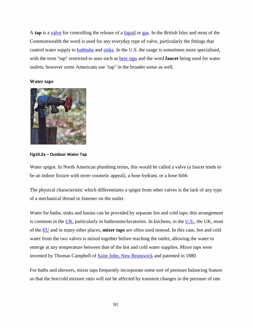
91
A tap is a valve for controlling the release of a liquid or gas. In the British Isles and most of the
Commonwealth the word is used for any everyday type of valve, particularly the fittings that
control water supply to bathtubs and sinks. In the U.S. the usage is sometimes more specialised,
with the term "tap" restricted to uses such as beer taps and the word faucet being used for water
outlets; however some Americans use "tap" in the broader sense as well.
Water taps
Fig10.2a – Outdoor Water Tap
Water spigot. In North American plumbing terms, this would be called a valve (a faucet tends to
be an indoor fixture with more cosmetic appeal), a hose hydrant, or a hose bibb.
The physical characteristic which differentiates a spigot from other valves is the lack of any type
of a mechanical thread or fastener on the outlet.
Water for baths, sinks and basins can be provided by separate hot and cold taps; this arrangement
is common in the UK, particularly in bathrooms/lavatories. In kitchens, in the U.S., the UK, most
of the EU and in many other places, mixer taps are often used instead. In this case, hot and cold
water from the two valves is mixed together before reaching the outlet, allowing the water to
emerge at any temperature between that of the hot and cold water supplies. Mixer taps were
invented by Thomas Campbell of Saint John, New Brunswick and patented in 1880.
For baths and showers, mixer taps frequently incorporate some sort of pressure balancing feature
so that the hot/cold mixture ratio will not be affected by transient changes in the pressure of one

92
or the other of the supplies. This helps avoid scalding or uncomfortable chilling as other water
loads occur (such as the flushing of a toilet).
Rather than two separate valves, mixer taps frequently use a single, more complex, valve whose
handle moves up and down to control the amount of water flow and from side to side to control
the temperature of the water. Especially for baths and showers, the latest designs do this using a
built in thermostat. These are known as thermostatic mixing valves, or TMVs, and can be
mechanical or electronic.
Fig. 10.2b - An outdoor tap.
Mixer taps are more difficult to fit in the UK than in other countries because traditional British
plumbing provides hot and cold water at different pressures.
If separate taps are fitted, it may not be immediately clear which tap is hot and which is cold.
The hot tap generally has a red indicator while the cold tap generally has a blue or green
indicator. In English-speaking countries, the taps are frequently also labeled with an "H" or "C".
Note that in countries with Romance languages, sometimes the letters "C" for hot and "F" for
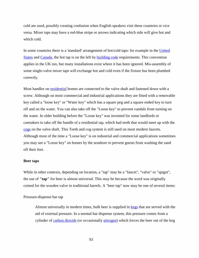
93
cold are used, possibly creating confusion when English speakers visit these countries or vice
versa. Mixer taps may have a red-blue stripe or arrows indicating which side will give hot and
which cold.
In some countries there is a 'standard' arrangement of hot/cold taps: for example in the United
States and Canada, the hot tap is on the left by building code requirements. This convention
applies in the UK too, but many installations exist where it has been ignored. Mis-assembly of
some single-valve mixer taps will exchange hot and cold even if the fixture has been plumbed
correctly.
Most handles on residential homes are connected to the valve shaft and fastened down with a
screw. Although on most commercial and industrial applications they are fitted with a removable
key called a "loose key" or "Water key" which has a square peg and a square ended key to turn
off and on the water. You can also take off the "Loose key" to prevent vandals from turning on
the water. In older building before the "Loose key" was invented for some landlords or
caretakers to take off the handle of a residential tap, which had teeth that would meet up with the
cogs on the valve shaft. This Teeth and cog system is still used on most modern faucets.
Although most of the time a "Loose key" is on industrial and commercial applications sometimes
you may see a "Loose key" on homes by the seashore to prevent guests from washing the sand
off their feet.
Beer taps
While in other contexts, depending on location, a "tap" may be a "faucet", "valve" or "spigot",
the use of "tap" for beer is almost universal. This may be because the word was originally
coined for the wooden valve in traditional barrels. A "beer tap" now may be one of several items:
Pressure-dispense bar tap
Almost universally in modern times, bulk beer is supplied in kegs that are served with the
aid of external pressure. In a normal bar dispense system, this pressure comes from a
cylinder of carbon dioxide (or occasionally nitrogen) which forces the beer out of the keg

94
and up a narrow tube to the bar. At the end of this tube is a valve built into a fixture
(usually somewhat decorative) on the bar. This is the beer tap, and opening it with a small
lever causes beer, pushed by the gas from the cylinder, to flow into the glass.
Portable keg tap
Sometimes, beer kegs designed to be connected to the above system are instead used on
their own, perhaps at a party or outdoor event. In this case, a self-contained portable tap
is required that allows beer to be served straight from the keg. Because the keg system
uses pressure to force the beer up and out of the keg, these taps must have a means of
supplying it. The typical "picnic tap" uses a hand pump to push air into the keg; this will
cause the beer to spoil faster but is perfectly acceptable when it will be consumed in a
short time. Portable taps with small CO2 cylinders are also available.
Fig. 10.3 - A gravity cask tap.
Cask beer tap
Beers brewed and served in the traditional way (typically cask ale) do not use artificial
gas. Taps for cask beer are simple on-off valves that are hammered into the end of the
cask (see keystone for details). When beer is served directly from the cask ("by gravity"),
as at beer festivals and some pubs, it simply flows out of the tap and into the glass. When
the cask is stored in the cellar and served from the bar, as in most pubs, the beer line is
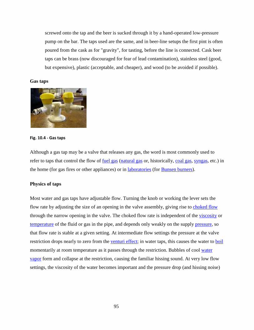
95
screwed onto the tap and the beer is sucked through it by a hand-operated low-pressure
pump on the bar. The taps used are the same, and in beer-line setups the first pint is often
poured from the cask as for "gravity", for tasting, before the line is connected. Cask beer
taps can be brass (now discouraged for fear of lead contamination), stainless steel (good,
but expensive), plastic (acceptable, and cheaper), and wood (to be avoided if possible).
Gas taps
Fig. 10.4 - Gas taps
Although a gas tap may be a valve that releases any gas, the word is most commonly used to
refer to taps that control the flow of fuel gas (natural gas or, historically, coal gas, syngas, etc.) in
the home (for gas fires or other appliances) or in laboratories (for Bunsen burners).
Physics of taps
Most water and gas taps have adjustable flow. Turning the knob or working the lever sets the
flow rate by adjusting the size of an opening in the valve assembly, giving rise to choked flow
through the narrow opening in the valve. The choked flow rate is independent of the viscosity or
temperature of the fluid or gas in the pipe, and depends only weakly on the supply pressure, so
that flow rate is stable at a given setting. At intermediate flow settings the pressure at the valve
restriction drops nearly to zero from the venturi effect; in water taps, this causes the water to boil
momentarily at room temperature as it passes through the restriction. Bubbles of cool water
vapor form and collapse at the restriction, causing the familiar hissing sound. At very low flow
settings, the viscosity of the water becomes important and the pressure drop (and hissing noise)
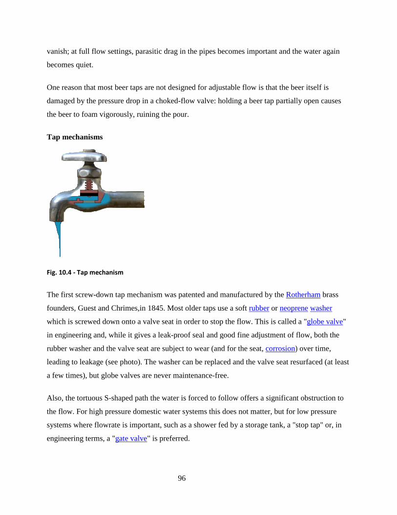
vanish; at full flow settings, parasitic drag in the pipes becomes important and the water again
becomes quiet.
One reason that most beer taps are not designed for adjustable flow is that the beer itself is
damaged by the pressure drop in a choked
the beer to foam vigorously, ruining the pour.
Tap mechanisms
Fig. 10.4 - Tap mechanism
The first screw-down tap mechanism was patented and manufactured by the
founders, Guest and Chrimes,in 1845. Most older taps use a soft
which is screwed down onto a valve seat in order to stop the flow. This is called a "
in engineering and, while it gives a leak
rubber washer and the valve seat are subject to wear (and for the seat,
leading to leakage (see photo). The washer can be replaced and the valve seat resurfaced (at least
a few times), but globe valves are never maintenance
Also, the tortuous S-shaped path the water is forced to follow offers a significant obstruction to
the flow. For high pressure domestic water systems this does not matter, but for low pressure
systems where flowrate is important, such as a shower fed by a storage tank, a "stop tap" or, in
engineering terms, a "gate valve" is preferred.
96
vanish; at full flow settings, parasitic drag in the pipes becomes important and the water again
One reason that most beer taps are not designed for adjustable flow is that the beer itself is
damaged by the pressure drop in a choked-flow valve: holding a beer tap partially open causes
the beer to foam vigorously, ruining the pour.
down tap mechanism was patented and manufactured by the Rotherham
founders, Guest and Chrimes,in 1845. Most older taps use a soft rubber or neoprene
a valve seat in order to stop the flow. This is called a "
in engineering and, while it gives a leak-proof seal and good fine adjustment of flow, both the
d the valve seat are subject to wear (and for the seat, corrosion) over time,
leading to leakage (see photo). The washer can be replaced and the valve seat resurfaced (at least
), but globe valves are never maintenance-free.
shaped path the water is forced to follow offers a significant obstruction to
the flow. For high pressure domestic water systems this does not matter, but for low pressure
lowrate is important, such as a shower fed by a storage tank, a "stop tap" or, in
" is preferred.
vanish; at full flow settings, parasitic drag in the pipes becomes important and the water again
One reason that most beer taps are not designed for adjustable flow is that the beer itself is
flow valve: holding a beer tap partially open causes
Rotherham brass
neoprene washer
a valve seat in order to stop the flow. This is called a "globe valve"
proof seal and good fine adjustment of flow, both the
) over time,
leading to leakage (see photo). The washer can be replaced and the valve seat resurfaced (at least
shaped path the water is forced to follow offers a significant obstruction to
the flow. For high pressure domestic water systems this does not matter, but for low pressure
lowrate is important, such as a shower fed by a storage tank, a "stop tap" or, in

97
Gate valves use a metal disc the same diameter as the pipe which is screwed into place
perpendicularly to the flow, cutting it off. There is no resistance to flow when the tap is fully
open, but this type of tap rarely gives a perfect seal when closed. In the UK this type of tap
normally has a wheel-shaped handle rather than a crutch or capstan handle.
Cone valves or ball valves are another alternative. These are commonly-found as the service
shut-off valves in more-expensive water systems and usually found in gas taps (and, incidentally,
the cask beer taps referred to above). They can be identified by their range of motion—only
90°—between fully on and fully off. Usually, when the handle is in line with the pipe the valve
is on, and when the handle is across the pipe it is closed. A cone valve consists of a shallowly-
tapering cone in a tight-fitting socket placed across the flow of the fluid. A ball valve uses a
spherical ball instead. In either case, a hole through the cone or ball allows the fluid to pass if it
is lined up with the openings in the socket through which the fluid enters and leaves; turning the
cone using the handle rotates the passage away, presenting the fluid with the unbroken surface of
the cone through which it cannot pass. Valves of this type using a cylinder rather than a cone are
sometimes encountered, but using a cone allows a tight fit to be made even with moderate
manufacturing tolerances. The ball in ball valves rotates within plastic seats.
Hands free infrared proximity sensors are replacing the standard valve. Thermostatically
controlled electronic dual-purpose mixing or diverting valves are used within industrial
applications to automatically provide liquids as required.
Foot controlled valves are installed within laboratory and healthcare/hospitals.
Modern taps often have aerators at the tip to help save water and reduce splashes. Without an
aerator, water usually flows out of the tap in one big stream. An aerator spreads the water flow
into many small droplets.
Modern bathroom and kitchen taps often use ceramic or plastic surfaces sliding against other
spring-loaded ceramic surfaces or plastic washers. These tend to require far less maintenance

98
than traditional globe valves and when maintenance is required, the entire interior of the valve is
usually replaced, often as a single pre-assembled cartridge.
Of the trio of well-respected faucet manufacturers in North American plumbing circles, Moen
and American Standard use cartridges (Moen's being O-ring based, American Standard's being
ceramic), while Delta uses easily-replaced rubber seats facing the cartridge(s). Each design has
its advantages: Moen cartridges tend to be easiest to find, American Standard cartridges have
nearly infinite lifespan in sediment-free municipal water, and Delta's rubber seats tend to be most
forgiving of sediment in well water.
Stopcock
Fig. 10.5 - A cast-iron stop-cock cover

99
Fig. 10.6 - A stopcock in use
Fig. 10 7 - A stopcock on a steam engine
The construction requirements for installing sanitary appliances are as
follows:
1. Cold and Hot water supply pipe installation – conduit or surface piping
2. Waste pipe installation – conduit or surface piping
3. Support fixing or construction to receive appliance
4. Rough plug provision for screwing or general fixing of part or all part of the
appliances.
QUIZ 10
Take a stroll around the school campus and locate the different taps, valves and stop cocks.
Identify them in terms of category.
100
WEEK 11: DRAINAGE SYSTEM USED IN BUILDINGS 1
Drainage Systems
Drainage systems are provisions made in, around and on buildings to get rid of water – surface,
storm and waste water.
The systems collect and transport water to convenient discharge points such as nearby streams or
rivers. It constitutes various forms of collection methods/sanctuaries/sumps and transportation
medium – pipes, open drainage channel, covered drainage channels and necessary
maintenance/cleaning points – manholes/inspection chambers.
The different types of drainage are:
Open drainage
Covered drainage
Buried drainage pipes
The different types of drainage materials include among others:
1. Ring culvert
2. Box culvert
3. Open concrete channels
4. Stone pitched V channels
5. Cement Asbestos drainage pipes
101
6. Coated steel drainage pipes
7. UPVC drainage pipes
The details on drainage system are as enunciated in the following further discussions:
Drainage schemes for buildings are necessary to remove waste water, foul water and surface
water.
Waste water and foul water join together and are disposed in a septic tank in rural areas or to a
foul water sewer in urban areas.
The foul water sewer discharges the sewerage to a treatment plant where it is settled, filtered and
chemically treated.
Surface water can be discharged into a soakaway, to a river or lake in rural areas or to the surface
water (or Storm Water) drain in urban areas. The storm water drain discharges water safely to a
river or lake.
A separate system of drainage is used where foul water and surface water are separated at source
and piped individually to a surface water drain or foul water drain.
The diagram below shows a typical arrangement for a small rural dwelling.

102
Fig. 11.1 – Drainage System for Small Dwelling
The figure 11.2 below shows a typical arrangement for a small urban dwelling.
Outlet from septic tank to
soakaway
into percolati

103
Fig. 11.2 – Drainage System for Small Dwelling in Urban Area
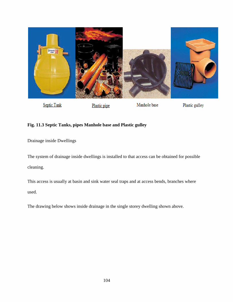
104
Fig. 11.3 Septic Tanks, pipes Manhole base and Plastic gulley
Drainage inside Dwellings
The system of drainage inside dwellings is installed to that access can be obtained for possible
cleaning.
This access is usually at basin and sink water seal traps and at access bends, branches where
used.
The drawing below shows inside drainage in the single storey dwelling shown above.

105
Separate and Combined Systems
A separate drainage system is one were the foul water and the surface water are always kept
separate.
This is shown in the two previous diagrams.
Fig 11.3 Soils and Wastes drainage in Single Storey
Dwelling
100mm diameter
foul water drains
through floor and
underground to
outside
W.C.
Sink
Bath
Basin
40mm waste from sink trap
connects to 100mm foul water
drain at floor level.
40mm waste from bath trap
connects to 100mm foul water drain
at floor level.
32mm waste from basin
trap connects to 100mm
foul water drain at floor
level.
100mm soil outlet from W.C. trap connects to
100mm foul water drain at floor level.
100mm underground
foul water drains

106
When a separate system is used then the sewerage treatment plant will not get overloaded in
periods of wet weather.
A combined system is no longer used and joins some or all of the surface water into the foul
water drainage system.
This means that both surface water and foul water will discharge into the sewerage treatment
plant. To avoid the treatment plant being overloaded, it may be possible to extract some foul
water at various points in the drainage network. This can be achieved if the surface water is less
dense than the foul water and tends to flow at the top in a drain. A separating device can be used
to divert surface water into a storm water channel or drain.
It is generally agreed that the installation and running costs of sewerage treatment plant can be
minimised if a separate system is adopted. For this reason the separate system is favoured by
local authorities.
A typical combined system is shown below but not recommended.
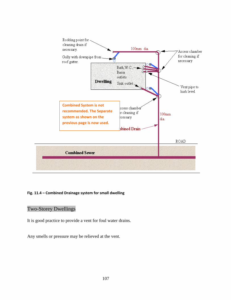
107
Fig. 11.4 – Combined Drainage system for small dwelling
Two-Storey Dwellings
It is good practice to provide a vent for foul water drains.
Any smells or pressure may be relieved at the vent.
Combined System is not
recommended. The Separate
system as shown on the
previous page is now used.

108
This may be achieved by continuing the foul water drain to high level above windows in a
building.
In a two-storey dwelling the bathroom is normally upstairs so the foul water drainage system will
be partly vertical, as shown below.
Fig. 11.5 – End Elevation of Two-Storey House Showing Vertical Soil and Vent Pipe
The vent is shown on a gable end, this can also be at the rear of a house or situated internally.

109
The system shown above is a single pipe system where there is one vertical soil and vent pipe. In
some installations the vents may be connected at each appliance (wash basin, urinal, etc.). This is
shown in the DESIGN POINTS section.
NOTE: Single pipe and two-pipe systems are not to be confused with separate and combined
systems as discussed on the previous page.
There are some points to note when designing any drainage scheme, these are:
Foul Water
1. Foul water is soil water from toilets and waste water from basins, baths, showers, etc.
2. The one-pipe system is favoured over the two-pipe system because there are fewer pipes
and it is more hygienic.

110

111
3. The two-pipe system uses a separate vent from each sanitary appliance, which are then
joined into a combined vent stack, whereas the single-stack system is simplified.
4. All systems are vented and trapped to exclude smells and foul air.
Traps are devices, which contain a water-seal of about 50mm to 75mm to prevent gases
escaping into sanitary fittings like wash basins, water closets, sinks, baths, showers, etc.
Foul water pipes exceeding 6.4 metres long are usually required to be vented.

112
5. If the waste pipe from a wash basin is at too steep a gradient, self-siphonage may occur.
This is where the contents of the trap are sucked out into the waste pipe because the water
flows away too quickly thus emptying the trap.
6. Induced siphonage can occur if a suction pressure develops in the drainage system. A
suction pressure of 500 N/m2 (50mm water gauge) will reduce the water level in a basin
trap by 25mm.

113
7. In badly designed systems backpressure can also occur which is sufficient to remove
water from a trap.
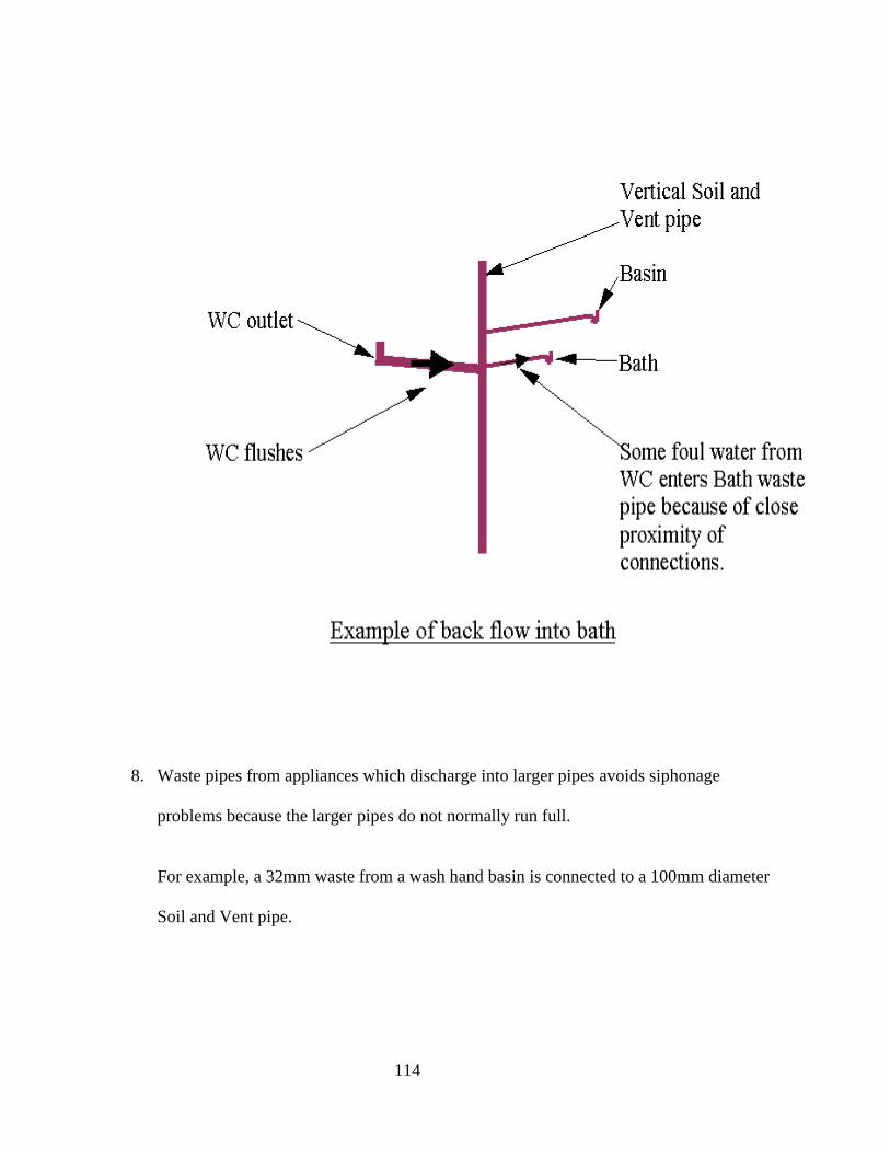
114
8. Waste pipes from appliances which discharge into larger pipes avoids siphonage
problems because the larger pipes do not normally run full.
For example, a 32mm waste from a wash hand basin is connected to a 100mm diameter
Soil and Vent pipe.
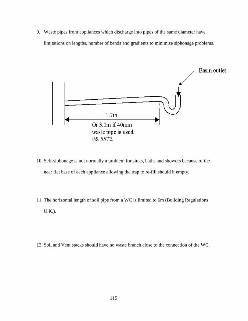
9. Waste pipes from appliances which discharge into pipes of the same diameter have
limitations on lengths, number of bends and gradients to minimise siphonage problems.
10. Self-siphonage is not normally a problem for sinks, baths and showers because of the
near flat base of each appliance allowing the trap to re
11. The horizontal length of soil pipe from a WC is limited to
U.K.).
12. Soil and Vent stacks should have
115
Waste pipes from appliances which discharge into pipes of the same diameter have
, number of bends and gradients to minimise siphonage problems.
is not normally a problem for sinks, baths and showers because of the
near flat base of each appliance allowing the trap to re-fill should it empty.
of soil pipe from a WC is limited to 6m (Building Regulations
Soil and Vent stacks should have no waste branch close to the connection of the WC.
Waste pipes from appliances which discharge into pipes of the same diameter have
, number of bends and gradients to minimise siphonage problems.
is not normally a problem for sinks, baths and showers because of the
fill should it empty.
(Building Regulations
waste branch close to the connection of the WC.

116
13. Sometimes it is not possible to prevent pressure fluctuations in pipework in which case
separate vent pipes should be installed. It may not be possible to limit the length of
branches or provide reasonable gradients in some installations.
14. A velocity of flow of 0.6 to 0.75 m/s should prevent stranding of solid matter in
horizontal pipes.
15. Gradients from 1 in 40 to 1 in 110 will normally give adequate flow velocities.
117
16. A range of 4 lavatory basins, the traps from which discharge into a straight run of 50mm
waste pipe not more than 4m long, with a fall of 1-21/2o, will give rise to a need for
venting. (reference British Standard No. 5572)
17. It is normal practice to connect a ground floor water closet straight into a manhole. Self-
siphonage and induced siphonage will not occur because of the large pipe from a W.C.
diameter (100mm) and because the drain is vented.
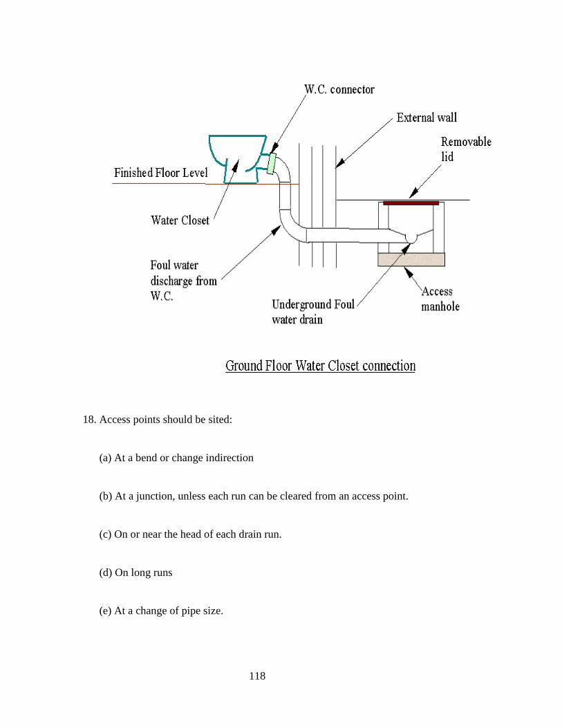
118
18. Access points should be sited:
(a) At a bend or change indirection
(b) At a junction, unless each run can be cleared from an access point.
(c) On or near the head of each drain run.
(d) On long runs
(e) At a change of pipe size.

119
Sizing
19. The soil & vent stack or branch to which at least one WC is connected must have
an internal diameter of at least 100mm.
Outlets from wash basins have a 32mm minimum diameter branch pipe and sinks
and baths have branch discharge pipes of 40mm diameter.
For large drainage installations pipe can be sized using discharge units and appropriate graphs.
20. Drains should be laid at a depth of 900mm (minimum) under roads and at least 600mm
below fields and gardens.
Drainage Schemes
The drainage scheme below shows a typical layout of a separate drainage system.
The building is a two-storey medical centre.
Can you identify the various drains and fittings?
QUIZ 11 – With the aid of simple sketches Differentiate between single and combined drainage
system.

120
WEEK 12: DRAINAGE SYSTEMS 2 (5.0)
The drawing below shows a typical drainage scheme with details.
Fig. 12.1 – Drainage scheme for Medical Centre

121
Nursing Home
The drawing above shows the plan of a single storey Nursing Home.
There are two separate buildings.
The yellow circles indicate foul water pipes exiting the building through the floor.
The pink squares show roof downpipes and gullies from the surface water drainage system.
When you examine the above drawing you will notice that there are a large number of 100mm
diameter underground pipes from sanitary appliances to manholes.
It may be possible to reduce the number of these underground pipes and have fewer connections
to manholes.
This can be achieved by a variety of methods as follows;
1. Join some sanitary appliances drainage pipework above ground outside as shown
below.
This method is not as neat as when all pipes are underground but the important aspect
of access is achieved with the cleaning eye.
40mm sanitary appliance
outlets above floor level.
External wall
50mm common
horizontal drain above
Cleaning eye
50mm to 100mm drain
connector
100mm
underground foul
Typical Connection of Two Sanitary Appliances
Outside
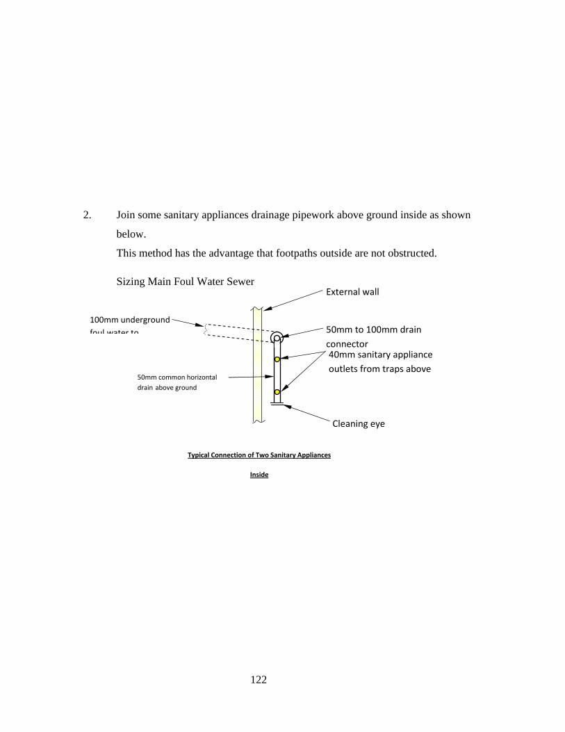
122
2. Join some sanitary appliances drainage pipework above ground inside as shown
below.
This method has the advantage that footpaths outside are not obstructed.
Sizing Main Foul Water Sewer
40mm sanitary appliance
outlets from traps above
External wall
50mm common horizontal
drain above ground
Cleaning eye
50mm to 100mm drain
connector
100mm underground
foul water to
Typical Connection of Two Sanitary Appliances
Inside

123
Appliance No. off
Discharge Units
each
Type of
application
Public
Total
Discharge units
Basin 5 3 15
Bath 2 12 24
Sink (large) 2 8 16
WC (9.0 litre) 5 10 50
Bidet 2 8 16
Washing Machine 1 8 8
Shower 5 8 40
Dishwasher 1 8 8
TOTAL = 177
From graph 150 mm pipe is suitable.

124
Pipe Gradients
Above ground and below ground horizontal drainage pipes should be laid to an adequate
gradient.
Gradients from 1 in 40 to 1 in 110 will normally give adequate flow velocities.
A gradient of 1 in 80 is suitable for commencing calculations for pipe schemes.
If a gradient is too steep i.e. steeper than 1 in 40, the liquid may run faster than the solids in the
sloping foul water pipe thus leaving the solids stranded, which could then block the pipe.
If the gradient is not steep enough, i.e. less than 1 in 110, then the pipe could still block if the
solids slow down and become stranded.

125
The fall in a pipe may be defined as the vertical amount by which the pipe drops over a distance.
The distance can be between sections of pipe or between manholes. The diagram below show
pipe fall and distance.
A gradient may be defined as fall divided by distance.
GRADIENT = FALL / DISTANCE
For example is a 24 metre section of drainage pipe has a fall of 0.30 metres, calculate the
gradient.
Gradient = 0.30 / 24
Gradient = 0.0125
This can be converted into a gradient written as a ratio or 1: some number.
Gradient = 1 / 0.0125 = 80
Gradient = 1 in 80
The above formula may be rearranged for Fall if the gradient is known:
Distance
Fall
Pipe Flow direction
FALL IN DRAINAGE PIPE

126
FALL = GRADIENT X DISTANCE
For example, calculate the fall in a 50 metre section of foul water pipework if the gradient is to
be 1 in 80.
A gradient of 1 in 80 is converted to a number instead of a ratio.
1 / 80 = 0.0125
Fall = Gradient x Distance
Fall = 0.0125 x 50
Fall = 0.625 metres or 625mm.
The previous diagram may be completed by adding a pipe gradient.
Distance
Fall
Pipe Flow direction
FALL & GRADIENT IN DRAINAGE PIPE
Gradient

127
Invert Levels
The Invert Level of a pipe is the level taken from the bottom of the inside of the pipe as shown
below.
The level at the crown of the pipe is the Invert level plus the internal diameter of the pipe plus
the pipe wall thickness. It may be necessary to use this in calculations when level measurements
are taken from the crown of a pipe.
Manholes
A manhole or access chamber is required to gain access to a drainage system for un-blocking,
cleaning, rodding or inspection. A typical manhole is shown below.
INVERT LEVEL OF PIPE
Section through pipe
Water level
Invert level
Crown of pipe
Cover and frame
Brick wall
Concrete base
Sloping
concrete/mortar
bed or haunching
BRICK BUILT MANHOLE
Pipe channel for
access to system

128
Manholes may be manufactured from masonry or precast concrete. Sometimes several precast
concrete rings are used to form a manhole which speeds up the on-site construction process.
Normally deep manholes below 1.0 metre in depth require step irons to assist access for a
workman.
Manholes and access chambers are also manufactured in PVC. An access chamber is not usually
large enough to admit a person but is suitable for access by cleaning rods or hose and they are
used for domestic applications, a common size of plastic access chamber is 450mm diameter. For
the domestic market plastic, fibreglass or galvanised steel lids may be used but cast iron lids are
required where traffic crosses.

129
A back drop manhole is used in areas where the surface level slopes as shown below.
If the undergroung sewer pipe is to stay below ground it must follow the average gradient of the
slope. This invariably means that the pipe gradient becomes too steep, resulting in the solids
being left stranded in the pipe therefore causing a blockage.
To overcome this problem the back drop manhole was developed, as shown below.
An easier way to construct a back drop manhole is to use an internal vertical section of pipe as
shown below.
Sloping
surface
Underground
sewer
Normal pipe
gradient
USE OF BACK DROP MANHOLES
Sloping
surface
Underground
sewer Excessive
gradient
SEWER ON A SLOPING SITE
Back Drop
manhole
Vertical
section of
Access cap
Back Drop
manhole
Access cap

130
Drainage Pipe Sizing
Foul Water Pipe Sizing
The following method is one way of sizing pipework.
1. Choose a minimum gradient for all pipes, say 1:80
2. Use the table below to calculate the total number of discharge units in pipe.
No. Appliance No. of units Total units
WC 14
basin 3
bath 7
shower 4
sink 6
washing machine 4
dish washer 4
3. Size section from pipe manufacturers’ graphs.
An example of a pipe-sizing graph is shown below.

131
Example
Size the foul water pipework for 12 houses from the DATA below in the table.
1. Use a minimum gradient of 1:80 for all pipes.
2. Discharge units from each house:

132
No. Appliance No. of units Total units
2 WC 14 28
2 basin 3 6
1 bath 7 7
1 shower 4 4
1 sink 6 6
0 washing machine 4 0
0 dish washer 4 0
Total 51
12 houses x 51 = 612 discharge units.

133
Flow graph gives 150mm-dia. foul drain since the convergence of the two lines on the
graph is between the pipe size 100mm diameter and 150mm diameter.
Surface Water Pipe Sizing
The following method is one way of sizing pipework.
1. Choose a minimum gradient for all pipes, say 1:80
2. Use the table below to calculate the flow rate in each section.
SURFACE TYPE AREA
(A) m2
IMPERMEABILITY
FACTOR (f)
TOTAL
(A x f)
Road or pavement 0.90
Roof 0.95
Path 0.75
Garden 0.25
Access road, parking 0.90
Total
3. The area of each surface is calculated from drawings.
4. The impermeability factor allows for water, which runs off each surface.
5. The flow rate (Q) for each house can be calculated from:
Q = area drained x rainfall intensity x impermeability factor
6. If Rainfall intensity = 50mm/hr, then Q becomes:
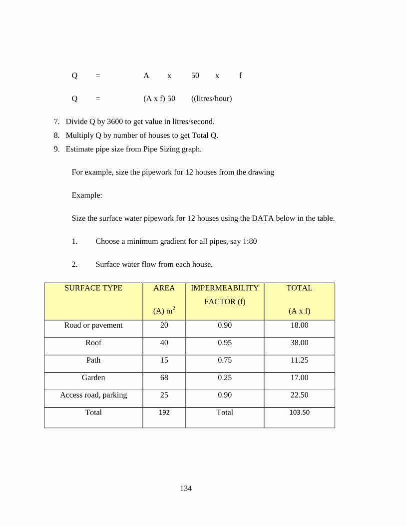
134
Q = A x 50 x f
Q = (A x f) 50 ((litres/hour)
7. Divide Q by 3600 to get value in litres/second.
8. Multiply Q by number of houses to get Total Q.
9. Estimate pipe size from Pipe Sizing graph.
For example, size the pipework for 12 houses from the drawing
Example:
Size the surface water pipework for 12 houses using the DATA below in the table.
1. Choose a minimum gradient for all pipes, say 1:80
2. Surface water flow from each house.
SURFACE TYPE AREA
(A) m2
IMPERMEABILITY
FACTOR (f)
TOTAL
(A x f)
Road or pavement 20 0.90 18.00
Roof 40 0.95 38.00
Path 15 0.75 11.25
Garden 68 0.25 17.00
Access road, parking 25 0.90 22.50
Total 192 Total 103.50
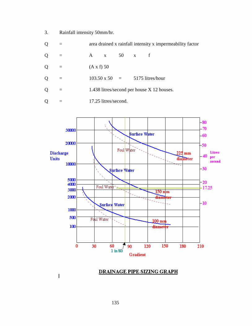
135
3. Rainfall intensity 50mm/hr.
Q = area drained x rainfall intensity x impermeability factor
Q = A x 50 x f
Q = (A x f) 50
Q = 103.50 x 50 = 5175 litres/hour
Q = 1.438 litres/second per house X 12 houses.
Q = 17.25 litres/second.

136
Flow graph gives 150mm dia. surface water drain since the point on the graph lies
between 100mm and 150mm
Septic Tanks
Introduction
A septic tank treats domestic sewage that is; the outlets from basins, baths, W.C.’s, showers,
sinks and other sanitary and domestic appliances.
In septic tanks the solids in the sewage settle to the bottom to form sludge.
Relatively clear liquid is left which forms a layer of scum on its surface. Bacteria feed on this
liquid and digest some of the matter in it.
The liquid then either passes into another settlement tank before passing to a watercourse or is
discharged underground through a network of pipes to filter through the soil in a soakaway
system.
The solids that build up at the bottom of the tank need to be removed about once a year.
Septic Tank
Effluent from
dwelling
Water to
soakaway
Manhole Lid
Vent and rodding access. Sometimes rodding access only.
Vent and rodding access
Ground Level
Compartment wall
Sludge
137
History
In 1860 a French man called Mouras built a masonry septic tank for a house in France.
After a dozen years, the tank was opened and found, contrary to all expectations, to be almost
free from solids. Mouras was able to patent his invention on 2 September, 1881. It is believed
that the septic tank was first introduced to the USA in 1883, to England in 1895 and to South
Africa (by the British military) in 1898.
Digestion
Sewage is allowed to rest in the septic tank for about 16 to 48 hours.
The process of digestion in the septic tank is done by bacteria.
These bacteria can be killed by certain chemicals.
The process of breaking down the organic matter in sewage is called anaerobic digestion since it
is largely outside the presence of air.
The digestion reduces the amount of sludge and makes the contents of the septic tank less
smelly. Normally it would take about two months to break down all the sludge in the tank so a
normally used septic tank will only partially break down the contents.
Too much bleach, detergents and other household chemicals may destroy the useful bacteria. As
a result the sewage will not be treated fully and may cause pollution problems. Emptying the
septic tank regularly will ensure the septic tank keeps working properly. If possible use
biodegradable 'septic safe' detergents.
Flow of Effluent
The concept is that effluent from the building should enter the tank at one end, be retained in the
tank for a period and discharged at the opposite end to enter the soakaway drain.
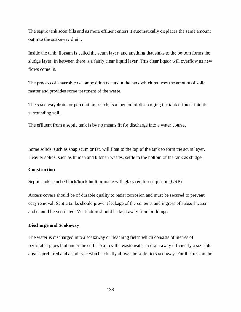
138
The septic tank soon fills and as more effluent enters it automatically displaces the same amount
out into the soakaway drain.
Inside the tank, flotsam is called the scum layer, and anything that sinks to the bottom forms the
sludge layer. In between there is a fairly clear liquid layer. This clear liquor will overflow as new
flows come in.
The process of anaerobic decomposition occurs in the tank which reduces the amount of solid
matter and provides some treatment of the waste.
The soakaway drain, or percolation trench, is a method of discharging the tank effluent into the
surrounding soil.
The effluent from a septic tank is by no means fit for discharge into a water course.
Some solids, such as soap scum or fat, will float to the top of the tank to form the scum layer.
Heavier solids, such as human and kitchen wastes, settle to the bottom of the tank as sludge.
Construction
Septic tanks can be block/brick built or made with glass reinforced plastic (GRP).
Access covers should be of durable quality to resist corrosion and must be secured to prevent
easy removal. Septic tanks should prevent leakage of the contents and ingress of subsoil water
and should be ventilated. Ventilation should be kept away from buildings.
Discharge and Soakaway
The water is discharged into a soakaway or ‘leaching field’ which consists of metres of
perforated pipes laid under the soil. To allow the waste water to drain away efficiently a sizeable
area is preferred and a soil type which actually allows the water to soak away. For this reason the

139
siting of a septic tank in heavy clay soil may not be suitable. Free draining sand and gravel’s
offer the best conditions.
The fall of distribution drains from the outlet should be as shallow as possible, i.e. 1 in 100 to 1in
200 to allow slow percolation. The bottom of the trench of the perforated pipe should be 900mm
above the seasonally high water table, or bedrock if possible. If the water table is closer to the
surface than 900mm then it may be possible to run the soakaway drain also closer to the surface
ensuring that water does not come up to ground level.
The trench in which the discharge perforated pipe runs can be backfilled with aggregate to assist
in percolation. The aggregate can be laid inside a wrap of geotextile material to impede the
silting up of the soakaway with silt from the surrounding trench.
The soakaway drain should be long enough to allow the water to percolate into the sub-soil.
Typical evaluation of the permeability of the soil will include a 'percolation test' to see how
quickly liquid will disappear into the soil. Clay soils will be less absorbent than coarser sandier
soils.
Notes:
• A soakaway should not be constructed where the ground water table is close to surface.
• In fine soil, the penetration distance of bacteria may be around 3m from the soakaway.
Coarser soils will enable greater penetration. Coliforms (gut bacteria) reportedly can
survive for as much as a month if they reach a source of groundwater.
• Limestone substrata will most probably be fissured, enabling septic tank effluent to flow
away too freely into the water table below.
• Boggy or peaty ground is also unsuitable since the percolation rate is very slow.
It is almost inevitable that the soakaway will eventually clog, so it is worth positioning the tank
and soakaway so that an alternative soakaway drain can be excavated in future.
BRE digest 151 Soakaways, details construction and sizing of soakaways.

140
Capacity
The size of the septic tank depends on the quantity of liquid being discharged to it which is
dependant on the number of people in the dwelling.
From BS 6297 Small domestic sewage treatment works and cesspools the Septic tank capacity is;
Capacity (m3) = Number of residents x 0.14 + 1.8
For a house with four occupants the capacity is;
Capacity (m3) = (4 x 0.14) + 1.8
Capacity (m3) = 2.36 m3.
Positioning
Septic tanks must be sited at least 7m from the habitable part of the building (preferably
downslope), within 30m of a suitable tanker access.
The drainage field or mound serving the septic tank must be at least 15m from any building, 10m
from any watercourse, permeable drain or soakaway, etc and not be covered by drives, roads or
paved areas.
Steep sloping sites should be avoided. Sites should be remote from ditches, streams and wells.
Compartments
Septic tanks are normally divided internally into compartments.
This allows the new effluent to settle and be digested before it is passed into the outlet.
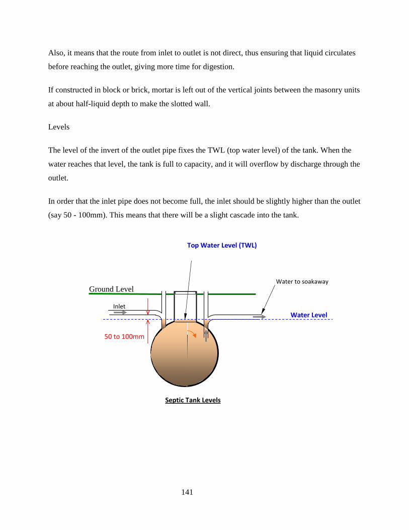
141
Also, it means that the route from inlet to outlet is not direct, thus ensuring that liquid circulates
before reaching the outlet, giving more time for digestion.
If constructed in block or brick, mortar is left out of the vertical joints between the masonry units
at about half-liquid depth to make the slotted wall.
Levels
The level of the invert of the outlet pipe fixes the TWL (top water level) of the tank. When the
water reaches that level, the tank is full to capacity, and it will overflow by discharge through the
outlet.
In order that the inlet pipe does not become full, the inlet should be slightly higher than the outlet
(say 50 - 100mm). This means that there will be a slight cascade into the tank.
Water to soakaway
Ground Level
Sludge
Septic Tank Levels
Water Level
Top Water Level (TWL)
50 to 100mm
Inlet

142
To ensure that the scum on top of the liquid neither impedes influent nor escapes as effluent,
both inlet and outlet pipes should be fitted with a tee as shown above.
Cess Pits
A cess pit is a sealed storage tank into which sewage is drained until it can be removed for
disposal.
The sewage is not treated in the tank just stored.
In some areas a septic tank is not suitable, there may be no suitable drainage in the subsoil, and a
cess pool is the only answer.
Older cess pits are usually cylindrical pits lined with either brick or concrete. Modern cess pits
are made from fibre glass, steel or polyethylene.
Current building regulations require cess pits to be able to hold at least 18,000 litres of sewage. It
is estimated that each person produces 115 litres of sewage a day. For a family of four this means
that the tank will need emptying about once a month.
Seepage Pits
Other sewage systems that have been used in the past are seepage pits or large soakaways. These
systems typically involve discharging septic tank treated sewage into a deep, cylindrical pit that
is open on the sides and bottom. Sometimes these pits can be constructed using honeycombed
brickwork, or concrete manhole sections with perforations in the walls. The holes are frequently
filled with large stones or gravel and a cover (probably in concrete ) placed over the hole. If the
ground strata for the whole depth is good and will absorb the effluent these can be satisfactory,
but if not then these can cause problems as the end result will be a large hole filled with septic
tank effluent.

143
Testing
Drains must be tested before and after backfilling trenches.
Water Test
BS 8005 gives details of Water tests.
This is suitable for sewers up to 750mm diameter.
The section of pipework to be tested is blocked at the lower end with a test pipe upstand at the
higher end. This test pipe is often located in an inspection chamber or manhole.
The test pipe has a 1.2 to 1.5 m head of water in it to produce a meaningful test with adequate
pressure.
This should stand for 2 hours and if necessary topped up to allow for limited porosity (clay
pipes). For the next 30 minutes, maximum leakage for 100 mm and 150 mm pipes is 0.05 and
0.08 litres per metre run respectively.
BS 8005 requires maximum leakage of 1 litre per hour per metre diameter per metre length of
pipe.
Drainage System Water Test
Pipe
filled
with
Manhole
1.5
metre
End
stopped
Section of
pipe under
test

144
Air Test -BS 8005 gives details of Air tests.
The drain is sealed between access chambers and pressure tested with hand bellows and a 'U'
gauge (manometer).
Build up air pressure initially to 100mm water gauge.
After 5 minutes adjust the air pressure to 100mm water gauge.
The pressure must not fall below 75 mm during the first 5 minutes, that is, a drop in pressure of
25mm over 5 minutes.
Smoke Test
The length of drain to be tested is sealed and smoke pumped into the pipes from the lower end.
The pipes should then be inspected for any trace of smoke.
Smoke pellets may be used in the smoke machine or with clay and concrete pipes they may be
applied directly to the pipe line.
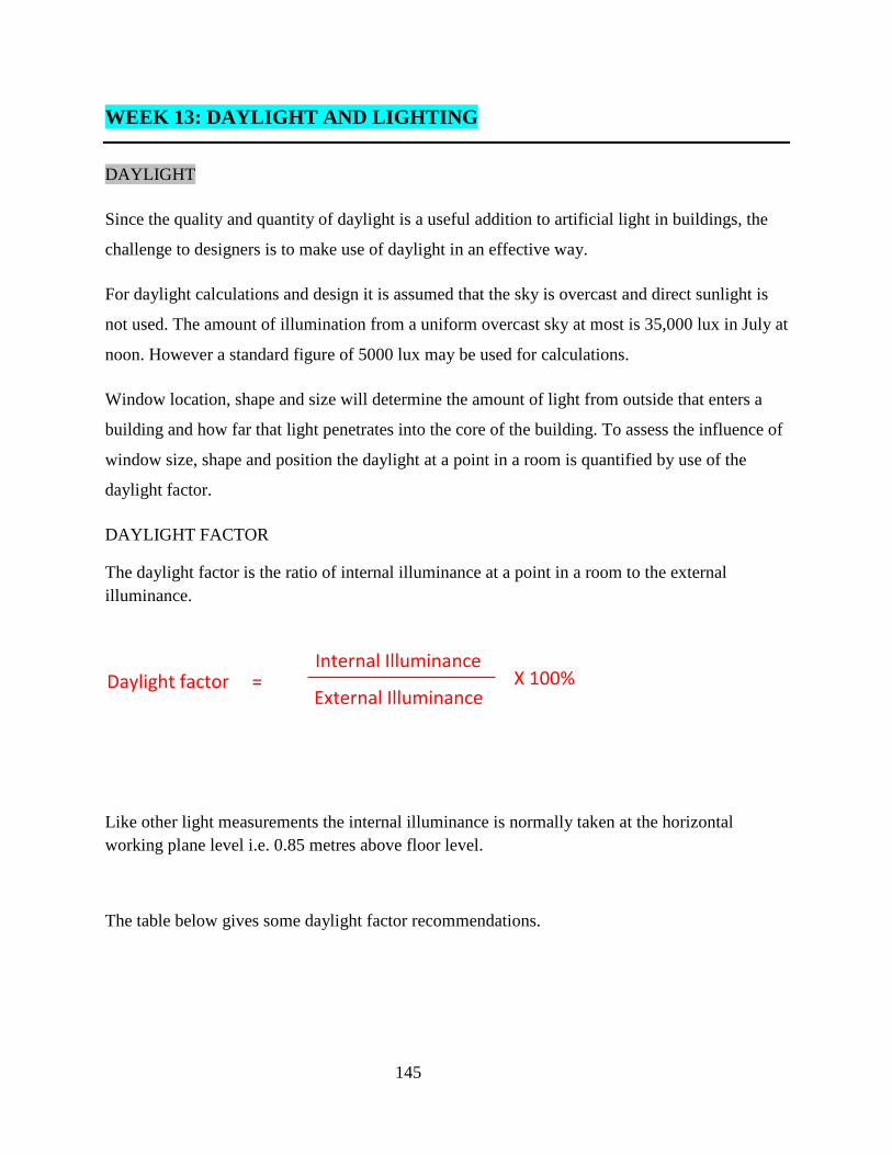
145
WEEK 13: DAYLIGHT AND LIGHTING
DAYLIGHT
Since the quality and quantity of daylight is a useful addition to artificial light in buildings, the
challenge to designers is to make use of daylight in an effective way.
For daylight calculations and design it is assumed that the sky is overcast and direct sunlight is
not used. The amount of illumination from a uniform overcast sky at most is 35,000 lux in July at
noon. However a standard figure of 5000 lux may be used for calculations.
Window location, shape and size will determine the amount of light from outside that enters a
building and how far that light penetrates into the core of the building. To assess the influence of
window size, shape and position the daylight at a point in a room is quantified by use of the
daylight factor.
DAYLIGHT FACTOR
The daylight factor is the ratio of internal illuminance at a point in a room to the external illuminance.
Like other light measurements the internal illuminance is normally taken at the horizontal working plane level i.e. 0.85 metres above floor level.
The table below gives some daylight factor recommendations.
Internal Illuminance
Daylight factor =
External Illuminance
X 100%
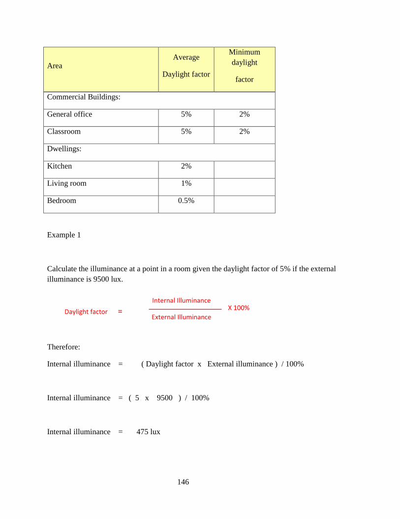
146
Area Average
Daylight factor
Minimum daylight
factor
Commercial Buildings:
General office 5% 2%
Classroom 5% 2%
Dwellings:
Kitchen 2%
Living room 1%
Bedroom 0.5%
Example 1
Calculate the illuminance at a point in a room given the daylight factor of 5% if the external illuminance is 9500 lux.
Therefore:
Internal illuminance = ( Daylight factor x External illuminance ) / 100%
Internal illuminance = ( 5 x 9500 ) / 100%
Internal illuminance = 475 lux
Internal Illuminance
Daylight factor =
External Illuminance
X 100%
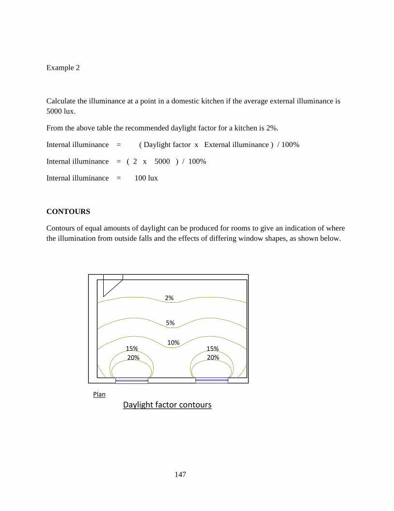
147
Example 2
Calculate the illuminance at a point in a domestic kitchen if the average external illuminance is 5000 lux.
From the above table the recommended daylight factor for a kitchen is 2%.
Internal illuminance = ( Daylight factor x External illuminance ) / 100%
Internal illuminance = ( 2 x 5000 ) / 100%
Internal illuminance = 100 lux
CONTOURS
Contours of equal amounts of daylight can be produced for rooms to give an indication of where the illumination from outside falls and the effects of differing window shapes, as shown below.
2%
5%
10% 15% 15%
20% 20%
Plan
Daylight factor contours
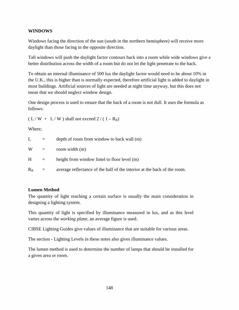
148
WINDOWS
Windows facing the direction of the sun (south in the northern hemisphere) will receive more daylight than those facing in the opposite direction.
Tall windows will push the daylight factor contours back into a room while wide windows give a better distribution across the width of a room but do not let the light penetrate to the back.
To obtain an internal illuminance of 500 lux the daylight factor would need to be about 10% in the U.K., this is higher than is normally expected, therefore artificial light is added to daylight in most buildings. Artificial sources of light are needed at night time anyway, but this does not mean that we should neglect window design.
One design process is used to ensure that the back of a room is not dull. It uses the formula as follows:
( L / W + L / W ) shall not exceed 2 / ( 1 – RB)
Where;
L = depth of room from window to back wall (m)
W = room width (m)
H = height from window lintel to floor level (m)
RB = average reflectance of the half of the interior at the back of the room.
Lumen Method The quantity of light reaching a certain surface is usually the main consideration in designing a lighting system.
This quantity of light is specified by illuminance measured in lux, and as this level varies across the working plane, an average figure is used.
CIBSE Lighting Guides give values of illuminance that are suitable for various areas.
The section - Lighting Levels in these notes also gives illuminance values.
The lumen method is used to determine the number of lamps that should be installed for a given area or room.

149
Calculating for the Lumen Method
The method is a commonly used technique of lighting design, which is valid, if the light fittings (luminaires) are to be mounted overhead in a regular pattern.
The luminous flux output (lumens) of each lamp needs to be known as well as details of the luminaires and the room surfaces.
Usually the illuminance is already specified e.g. office 500 lux, kitchen 300 lux, the designer chooses suitable luminaires and then wishes to know how many are required.
The number of lamps is given by the formula:
where,
N = number of lamps required.
E = illuminance level required (lux)
A = area at working plane height (m2)
F = average luminous flux from each lamp (lm)
UF= utilisation factor, an allowance for the light distribution of the luminaire
and the room surfaces.
MF= maintenance factor, an allowance for reduced light output because of deterioration and dirt.
Example 1
A production area in a factory measures 60 metres x 24 metres.
E x A N =
F x UF x MF

150
Find the number of lamps required if each lamp has a Lighting Design Lumen (LDL) output of 18,000 lumens.
The illumination required for the factory area is 200 lux.
Utilisation factor = 0.4
Lamp Maintenance Factor = 0.75
N = ( 200 lux x 60m x 24m ) / ( 18,000 lumens x 0.4 x 0.75 )
N = 53.33
N = 54 lamps.
Spacing
The aim of a good lighting design is to approach uniformity in illumination over the working plane.
Complete uniformity is impossible in practice, but an acceptable standard is for the minimum to be at least 70% of the maximum illumination level.
This means, for example, that for a room with an illumination level of 500 lux, if this is taken as the minimum level, then the maximum level in another part of the room will be no higher than 714 lux as shown below.
500 / 0.7 = 714 lux
Data in manufacturer's catalogues gives the maximum ratio between the spacing (centre to centre) of the fittings and their height ( to lamp centre) above the working plane (0.85 metres above f.f.l.)
0.85 metres
Spacing distance Mounting
Height
f.f.l.

This percentage value is known as a Daylight Factor.
Daylight Factor Definition
The Daylight Factor is defined as the ratio of the illuminance at a particular point within an
enclosure to the simultaneous unobstructed outdoor illuminance under the same sky conditions,
expressed as a percentage. Once both the Daylight Factor and Design Sky are known
multiplying the two together gives the illuminance level (in either lux or foot candles) due to
daylight at the point.
Daylight Factor Calculations
Working out the Daylight Factor in different areas of a building can be a time consuming and
laborious process. In most cases it is done using a computer program, of which there are quite a
few to choose from. However, a good knowledge of manual calculation methods is very
important if you are to fully understand the processes involved and therefore
computer programs in the most appropriate ways. There are a number of ways to calculate the
Daylight Factor for a space:
• Average Daylight Factor
This is quite a simple equation that requires only a few parameters and makes quite a
few assumptions about the nature of your space. The result is a single value room
average daylight factor.
• Daylight Factor Protractors
Also known as the Split Flux Method, this involves overlaying protractors onto the
plans and sections of your building. This can be done directly on print
the new Square One DF Protractor tool
your favourite CAD tool.
151
This percentage value is known as a Daylight Factor.
Daylight Factor Definition
is defined as the ratio of the illuminance at a particular point within an
enclosure to the simultaneous unobstructed outdoor illuminance under the same sky conditions,
expressed as a percentage. Once both the Daylight Factor and Design Sky are known
multiplying the two together gives the illuminance level (in either lux or foot candles) due to
Daylight Factor Calculations
Working out the Daylight Factor in different areas of a building can be a time consuming and
borious process. In most cases it is done using a computer program, of which there are quite a
few to choose from. However, a good knowledge of manual calculation methods is very
important if you are to fully understand the processes involved and therefore
computer programs in the most appropriate ways. There are a number of ways to calculate the
Average Daylight Factor
s is quite a simple equation that requires only a few parameters and makes quite a
few assumptions about the nature of your space. The result is a single value room
average daylight factor.
Daylight Factor Protractors
Also known as the Split Flux Method, this involves overlaying protractors onto the
plans and sections of your building. This can be done directly on print
DF Protractor tool , directly over a scanned image or within
your favourite CAD tool.
is defined as the ratio of the illuminance at a particular point within an
enclosure to the simultaneous unobstructed outdoor illuminance under the same sky conditions,
expressed as a percentage. Once both the Daylight Factor and Design Sky are known, simply
multiplying the two together gives the illuminance level (in either lux or foot candles) due to
Working out the Daylight Factor in different areas of a building can be a time consuming and
borious process. In most cases it is done using a computer program, of which there are quite a
few to choose from. However, a good knowledge of manual calculation methods is very
important if you are to fully understand the processes involved and therefore apply these
computer programs in the most appropriate ways. There are a number of ways to calculate the
s is quite a simple equation that requires only a few parameters and makes quite a
few assumptions about the nature of your space. The result is a single value room-
Also known as the Split Flux Method, this involves overlaying protractors onto the
plans and sections of your building. This can be done directly on print-outs or, using
rectly over a scanned image or within
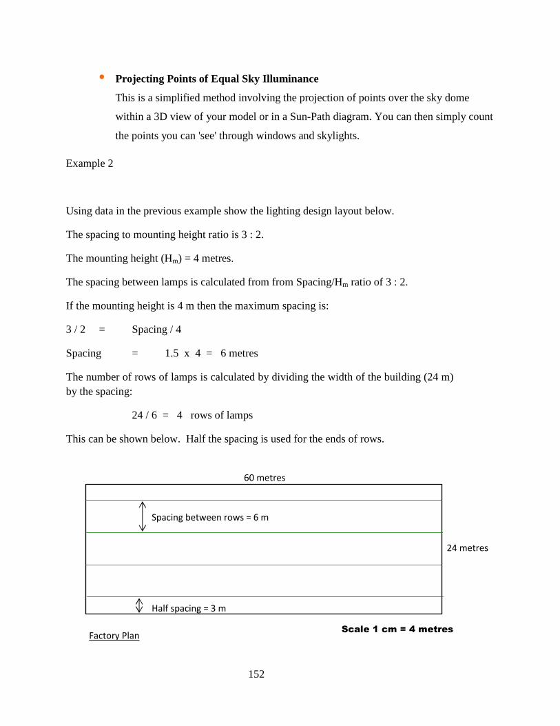
152
• Projecting Points of Equal Sky Illuminance
This is a simplified method involving the projection of points over the sky dome
within a 3D view of your model or in a Sun-Path diagram. You can then simply count
the points you can 'see' through windows and skylights.
Example 2
Using data in the previous example show the lighting design layout below.
The spacing to mounting height ratio is 3 : 2.
The mounting height (Hm) = 4 metres.
The spacing between lamps is calculated from from Spacing/Hm ratio of 3 : 2.
If the mounting height is 4 m then the maximum spacing is:
3 / 2 = Spacing / 4
Spacing = 1.5 x 4 = 6 metres
The number of rows of lamps is calculated by dividing the width of the building (24 m) by the spacing:
24 / 6 = 4 rows of lamps
This can be shown below. Half the spacing is used for the ends of rows.
Factory Plan
24 metres
60 metres
Scale 1 cm = 4 metres
Half spacing = 3 m
Spacing between rows = 6 m

153
The number of lamps in each row can be calculated by dividing the total number of lamps found in example 1 by the number of rows.
Total lamps 54 / 4 = 13.5 goes up to nearest whole number = 14 lamps in each row.
The longitudinal spacing between lamps can be calculated by dividing the length of the building by the number of lamps per row.
Length of building 60 m / 14 = 4.28 metres.
There will be half the spacing at both ends = 4.28 / 2
= 2.14 metres
This can be shown below.
Factory Plan
24 metres
60 metres
Scale 1 cm = 4
metres
6 m
4.28
metres
Half Spacing 2.14
metres

154
The total array of fittings can be shown below.
For more even spacing the layout should be re-considered.
The spacing previously was 6 m between rows and 4.28 m between lamps.
If 5 rows of 11 lamps were used then the spacing would be:
Spacing between rows = 24 / 5 = 4.8 metres
Spacing between lamps = 60 / 11 = 5.45 metres
Installed Flux
Sometimes it is useful to know the total amount of light or flux, which has to be put into a space.
Installed flux (lm) = Number of fittings (N) x Number of lamps per fitting x L.D.L. output of each lamp (F)
Lighting is the illumination of buildings. There are two methods of lighting in building – Natural
and Artificial lighting.
Factory Plan
24 metres
60 metres
Scale 1 cm = 4 metres
6 m
4.28 m Light Fittings

155
Natural lighting, also referred to as Day light, derives its illumination ability from the sun. The
sunshine illuminates the environment within which the building is and the openings under
fenestration in building allowed controllable amount of natural lighting into buildings.
Artificial lighting derives its source from electrical illuminants – incandescent lamps or
fluorescent lights. They are provided under electrical provision in buildings.
Provision of Natural lighting in Buildings
Natural lighting in building is provided by making provision in building to admit adequate
daylight into it. This provision is referred to as FENESTRATION or commonly known as
Openings in Building. The openings include among others windows, doors, screen walling, roof
light, lighting glass blocks etc.
Provision of Artificial Lighting in Buildings
Artificial lighting as previously mentioned is provided by the use of incandescent lamps or
fluorescent lights. The lights are powered by various sources of energy but most commonly by
electrical energy. This is part of the electrical engineering design of buildings. They form part of
electrical installation in buildings.
The integration of Lighting: Natural and Artificial in building.
The two lighting method are usually combined effectively to minimize the use of artificial
lighting that is usually costly to use. This is achieved by architectural design provisions in
conjunction with electrical engineering design provisions.

156
WEEK 14: ELECTRICAL FITTINGS AND CONTROL
Cables
Cables are used for electrical wiring in building. The conduct current to various fittings. Various
fittings require different level or amount of current to run or drive them. The flow of current is
dependent on the size, type and quality of cable use. An improper use of cables result in heat
generation and possibly fire hazard hence the importance proper cable type and size selection
and use for the different types of fittings in buildings.
The following are the different types of cables based on form, material and sizes (some of the
cables are as shown in figure 14.1:
1. Single core cables
2. Double core cables
3. Multiple core cables
4. Armoured cables
5. Copper cables
6. Aluminum cables
7. 1.0 mm2
8. 1.5 mm2
9. 2.5 mm2
10. 4.0 mm2
11. 6.0 mm2
12. PVC insulated cables etc.

157
Fig. 14.1 – Samples of Electrical Cables
Electrical design and installation involve the use of symbols and conduit fittings the detail
description of which is beyond this syllabus, but for the purpose of a general understanding the
following figures 14.2 14.6 shows the various items that fall under the aforementioned.
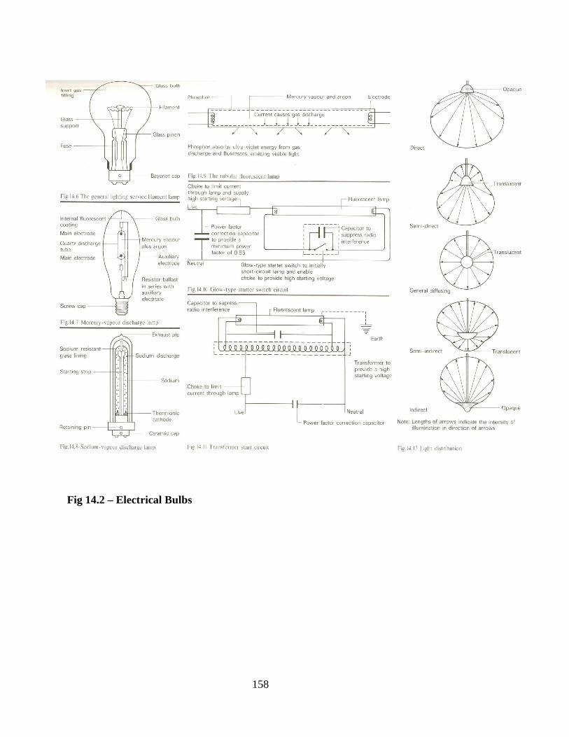
158
Fig 14.2 – Electrical Bulbs
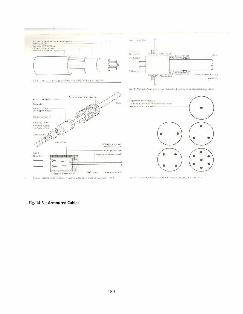
159
Fig. 14.3 – Armoured Cables

160
Fig.14.4 – Conduit Materials

161
Fig. 14.5 – Ceiling Fittings

162
Fig. 14. 6 – Lighting Point Details 1
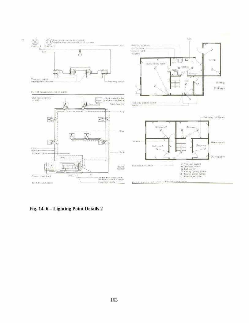
163
Fig. 14. 6 – Lighting Point Details 2

164
Lighting symbols for Installations
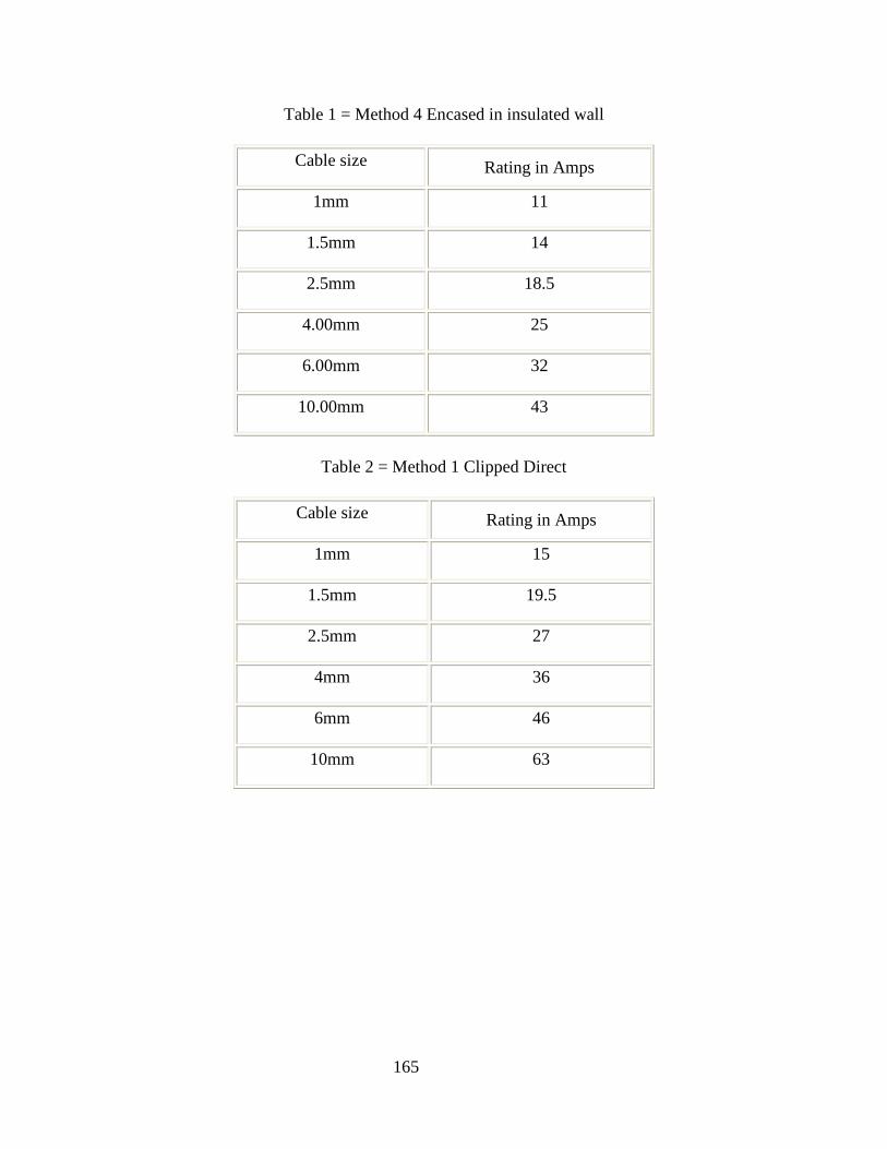
165
Table 1 = Method 4 Encased in insulated wall
Cable size Rating in Amps
1mm 11
1.5mm 14
2.5mm 18.5
4.00mm 25
6.00mm 32
10.00mm 43
Table 2 = Method 1 Clipped Direct
Cable size Rating in Amps
1mm 15
1.5mm 19.5
2.5mm 27
4mm 36
6mm 46
10mm 63

166
List of Electrical Fittings and Controls
The following are the list of electrical fittings and controls showing their uses:
1. Socket outlet - use for 13A and 15A power sockets
2. Switches - use for putting on/off light
3. Wall Bracket - use for lighting fitting
4. Bulk head fitting - use for external lighting
5. Ceiling Rose - use as power point terminal
6. Cooker Control Unit - use for socket and power supply to
cooker in kitchen
7. Distribution Board - use for current distribution to various
points in buildings
8. ELCB - use for power supply protection, it
serves as circuit-breaker in the event of
short circuiting.
9. Change over switch - use for controls in double source power
supply
10. Others
167
Construction Provisions made for electrical fittings.
Construction provisions are for electrical fittings in buildings to allow for a seamless and highly
integrated installation at various points of the building.
The essential provisions made arising from the design detail are as follows:
1. Conduit pipe installation within walls, floors
2. Fixing base to receive fittings
3. Bored holes for passage of pipes/cables
4. Others
QUIZ 14
Sketch a three bedroom flat and show the electrical and power supply design, use keys
appropriately.

168
WEEK 15: ELECTRICAL FITTINGS AND CONTROL2
Design and Installation of electric wiring:
Class work involving the design and installation of electrical for a three bedroom apartment.
THE REVIEW ALL THAT HAS BEEN DONE SO FAR AND ANSWERING OF THE
FOLLOWING QUIZ IN CLASS TO MARK THE END OF COURSE:
ASSIGNMENTS
1. Choose appropriate lamp and fitting types for the buildings listed below;
(a) Hospital ward
(b) Factory
(c) Bank hall
(d) School classroom
(e) Large Public Library
(f) Football Stadium
(g) Retail Outlet window
(h) Temporary lighting for construction site.
(i) Scientific experimentation Laboratory.
(j) Cinema
2. Describe a typical emergency lighting scheme for a large building.
Discuss the systems and categories that may be used.
Describe various luminaries and wiring systems that can be used in emergency
lighting.

169
Discuss the location of fittings.
3. Describe, with the aid sketches, typical control gear for gas discharge and low
voltage light fittings.
4. Produce an appropriate lighting scheme for the Leisure Centre building.
Choose fittings and produce a design that is efficient, energy saving and cost
effective.
Related Documents
![BLD 103 Building Construction I Combined[2]](https://static.cupdf.com/doc/110x72/55351aed4a7959967b8b4638/bld-103-building-construction-i-combined2.jpg)


