BLACKMER LIQUEFIED GAS PUMPS FOR CO2 SERVICE TRUCK AND BASE MOUNTED INSTALLATION, OPERATION, AND MAINTENANCE INSTRUCTIONS MODELS: CRL4 Discontinued Model: TCRL4 & TCRLF4A 962009 INSTRUCTIONS NO. 701-C00 Page 1 of 12 Section 700 Effective June 2001 Replaces 785/G Feb 1988 TABLE OF CONTENTS Page SAFETY DATA ..................................................................1-2 PUMP DATA ..........................................................................2 Technical Data .......................................................2 Initial Start Up Information .....................................2 Pump With Welded Connections...........................2 Installation and Operation - CRL Motor Driven ..........3-5 Pre-Installation Cleaning .......................................3 Location and Piping...............................................3 Pump Mounting .....................................................3 Coupling Alignment ...............................................3 V-Belt Drive ...........................................................4 Internal Pump Relief Valve and Bypass Valve ......4 Pump Rotation.......................................................5 To Change Pump Rotation ....................................5 Pre-Start Up Check List .........................................5 Start Up Procedures ..............................................5 Relief Valve Setting and Adjustment .....................5 Installation and Operation - CRL Truck Mount ...........6-8 Truck Mounting......................................................6 Pre-Installation Cleaning .......................................6 Location and Piping...............................................6 Auxiliary Inlet .........................................................6 Pump Drive............................................................6 Hydraulic Drive ......................................................6 Internal Pump Relief Valve and Bypass Valve ......7 Pump Rotation.......................................................7 To Change Pump Rotation ....................................7 Pre-Start Up Check List .........................................7 Start Up Procedures ..............................................7 Relief Valve Setting and Adjustment .....................8 Pump Speed..........................................................8 MAINTENANCE ....................................................................8-11 Lubrication .............................................................8 Vane Replacement ................................................9 Pump Disassembly................................................9 Pump Assembly ....................................................9 GENERAL PUMP TROUBLESHOOTING ................11-12 NOTICE: Blackmer CO2 pumps MUST only be installed in systems which have been designed by qualified engineering personnel. The system MUST conform to all applicable local and national regulations and safety standards. This manual is intended to assist in the installation and operation of the Blackmer CO2 pumps, and MUST be kept with the pump. Blackmer CO2 pump service shall be performed by qualified technicians ONLY. Service shall conform to all applicable local and national regulations and safety standards. Thoroughly review this manual, all instructions and hazard warnings, BEFORE performing any work on the Blackmer CO2 pumps. Maintain ALL system and Blackmer CO2 pump operation and hazard warning decals. SAFETY DATA NOTE: Numbers in parentheses following individual parts indicate reference numbers on the corresponding Blackmer Parts List. This is a SAFETY ALERT SYMBOL. When you see this symbol on the product, or in the manual, look for one of the following signal words and be alert to the potential for personal injury, death or major property damage. Warns of hazards that WILL cause serious personal injury, death or major proper ty damage. Warns of hazards that CAN cause serious personal injury, death or major proper ty damage. Warns of hazards that CAN cause personal injury or proper ty damage. NOTICE: Indicates special instructions which are very impor tant and must be followed. DISCONNECTING FLUID OR PRESSURE CONTAINMENT COMPONENTS DURING PUMP OPERATION CAN CAUSE SERIOUS PERSONAL INJURY, DEATH OR MAJOR PROPERTY DAMAGE. Hazardous pressure can cause personal injury or property damage.

Welcome message from author
This document is posted to help you gain knowledge. Please leave a comment to let me know what you think about it! Share it to your friends and learn new things together.
Transcript
BLACKMER LLIQUEFIED GGAS PPUMPSFFOORR CCOO2 SSEERRVVIICCEE TTRRUUCCKK AANNDD BBAASSEE MMOOUUNNTTEEDD
INSTALLATION, OPERATION, AND MAINTENANCE INSTRUCTIONSMODELS: CRL4
Discontinued Model: TCRL4 & TCRLF4A
962009INSTRUCTIONS NO. 701-C00Page 1 of 12Section 700Effective June 2001Replaces 785/G Feb 1988
TABLE OF CONTENTS Page
SAFETY DATA ..................................................................1-2PUMP DATA ..........................................................................2
Technical Data.......................................................2Initial Start Up Information .....................................2Pump With Welded Connections...........................2
Installation and Operation - CRL Motor Driven ..........3-5Pre-Installation Cleaning .......................................3Location and Piping...............................................3Pump Mounting .....................................................3Coupling Alignment ...............................................3V-Belt Drive ...........................................................4Internal Pump Relief Valve and Bypass Valve ......4Pump Rotation.......................................................5To Change Pump Rotation ....................................5Pre-Start Up Check List.........................................5Start Up Procedures ..............................................5Relief Valve Setting and Adjustment .....................5
Installation and Operation - CRL Truck Mount ...........6-8Truck Mounting......................................................6Pre-Installation Cleaning .......................................6Location and Piping...............................................6Auxiliary Inlet .........................................................6Pump Drive............................................................6Hydraulic Drive ......................................................6Internal Pump Relief Valve and Bypass Valve ......7Pump Rotation.......................................................7To Change Pump Rotation ....................................7Pre-Start Up Check List.........................................7Start Up Procedures ..............................................7Relief Valve Setting and Adjustment .....................8Pump Speed..........................................................8
MAINTENANCE ....................................................................8-11Lubrication.............................................................8Vane Replacement ................................................9Pump Disassembly................................................9Pump Assembly ....................................................9
GENERAL PUMP TROUBLESHOOTING ................11-12
NOTICE:Blackmer CO2 pumps MUST only be installed insystems which have been designed by qualifiedengineering personnel. The system MUST conform toall applicable local and national regulations and safetystandards.This manual is intended to assist in the installationand operation of the Blackmer CO2 pumps, and MUSTbe kept with the pump.Blackmer CO2 pump service shall be performed byqualified technicians ONLY. Service shall conform toall applicable local and national regulations and safetystandards.Thoroughly review this manual, all instructions andhazard warnings, BEFORE performing any work onthe Blackmer CO2 pumps.Maintain ALL system and Blackmer CO2 pumpoperation and hazard warning decals.
SAFETY DATA
NOTE: Numbers in parentheses following individualparts indicate reference numbers on the correspondingBlackmer Parts List.
This is a SAFETY ALERT SYMBOL.When you see this symbol on the product, or in the manual, look for
one of the following signal words and be alert to the potential forpersonal injury, death or major proper ty damage.
Warns of hazards that WILL cause serious personal injury, death or major proper ty damage.
Warns of hazards that CAN cause serious personal injury, death or major proper ty damage.
Warns of hazards that CAN cause personal injuryor proper ty damage.
NOTICE:Indicates special instructions which are very
impor tant and must be followed.
DISCONNECTING FLUID ORPRESSURE CONTAINMENTCOMPONENTS DURING PUMPOPERATION CAN CAUSE SERIOUSPERSONAL INJURY, DEATH OR MAJORPROPERTY DAMAGE.
Hazardous pressurecan cause personal injury orproperty damage.

SAFETY DATAFAILURE TO DISCONNECT ANDLOCKOUT ELECTRICAL POWERBEFORE ATTEMPTING MAINTENANCECAN CAUSE SHOCK, BURNS ORDEATH.Hazardous voltage.
Can shock, burn or cause death.
Hazardousmachinery cancause seriouspersonal injury.
FAILURE TO DISCONNECT ANDLOCKOUT ELECTRICAL POWERBEFORE ATTEMPTING MAINTENANCECAN CAUSE SERIOUS PERSONALINJURY OR DEATH.
Hazardous or toxicfluids can causeserious injury.
IF PUMPING HAZARDOUS FLUIDSSYSTEM MUST BE FLUSHED PRIORTO PERFORMING SERVICE.
DO NOT ATTEMPT TO OPEN THE PUMPUNTIL YOU HAVE BLED OFF THEPRESSURE. ON SYSTEMS WITHMETERS, THE DIFFERENTIAL VALVEWILL KEEP LIQUID UNDER PRESSUREIN THE PUMP, METER AND PIPINGEVEN WHEN THE HOSE IS EMPTIED.
Hazardous pressurecan cause personalinjury or propertydamage.
PUMP DATA
Model Designations:Motor Drive & Truck Mount CRL4Discontinued TCRL4, TCRLF4A
Torque Required @ 100 psi 205 lbs ft (6.9 bar) (278 Nm)
Maximum Temperature 240oF (115oC)
Minimum Temperature -30oF (-34oC)
Maximum Pump Speed 640 RPM
Maximum Differential Pressure 100 psi ( 6.9 bar)
Maximum Working Pressure 525 psi ( 36.2 bar)(Inlet Pressure + Differential Pressure)
INITIAL START UP INFORMATION
Model No.
Serial No.
Date of Installation:
Discharge Gauge Reading:
Inlet Gauge Reading:
Flow Rate:
TECHNICAL DATA
PUMP WITH WELDED CONNECTIONSNOTICE:
FOR PIPING CONNECTIONS REQUIRING WELDING THEPUMP’S NON-METALLIC O-RINGS MUST BE REMOVEDPRIOR TO WELDING. FAILURE TO DO SO WILLDAMAGE THE O-RINGS.
Before welding the piping, remove the O-rings from underthe inlet flange, outlet flange and relief valve cover asindicated in Figure 1.
Reinstall the inlet and outlet flanges. Weld the piping to thethe inlet and outlet flanges. After the welding is complete,reinstall the O-rings.
Figure 1
2
FAILURE TO SET THE VEHICLEEMERGENCY BRAKE AND CHOCKWHEELS BEFORE PERFORMINGSERVICE CAN CAUSE SEVEREPERSONAL INJURY OR PROPERTYDAMAGE.
Hazardous machinerycan cause severepersonal injury orproperty damage.
FAILURE TO RELIEVE SYSTEMPRESSURE PRIOR TO PERFORMINGPUMP SERVICE OR MAINTENANCECAN CAUSE PERSONAL INJURY ORPROPERTY DAMAGE.Hazardous pressure
can cause personalinjury or propertydamage.
O-RING
O-RINGO-RINGO-RINGO-RING
O-RING
NOTICE:THIS PUMP CONTAINS SOME RESIDUAL TEST FLUIDAND RUST INHIBITOR. IF NECESSARY, FLUSH PUMPPRIOR TO USE.
Hazardous voltage.Can shock, burn or cause death.
Install, ground and wire to local andNational Electrical Code requirements.
Install an all-leg disconnect switch nearthe unit motor.
Disconnect and lockout electrical powerbefore installation or service.
Electrical supply MUST match motor nameplatespecifications.Motors equipped with thermal protection automaticallydisconnect motor electrical circuit when overload exists.Motor can start unexpectedly and without warning.
NOTICE:BLACKMER CO2 PUMPS MUST ONLY BE INSTALLEDIN SYSTEMS DESIGNED BY QUALIFIED ENGINEERINGPERSONNEL. SYSTEM DESIGN MUST CONFORMWITH ALL APPLICABLE REGULATIONS AND CODESAND PROVIDE WARNING OF ALL SYSTEM HAZARDS.
INSTALLATION AND OPERATION CRL BASE MOUNTED MOTOR DRIVEN PUMPS
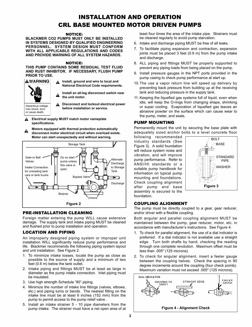
PRE-INSTALLATION CLEANINGForeign matter entering the pump WILL cause extensivedamage. The supply tank and intake piping MUST be cleanedand flushed prior to pump installation and operation.LOCATION AND PIPINGAn improperly designed piping system or improper unitinstallation WILL significantly reduce pump performance andlife. Blackmer recommends the following piping system layoutand unit installation. See Figure 2.1. To minimize intake losses, locate the pump as close as
possible to the source of supply and a minimum of twofeet (0.6 m) below the tank outlet.
2. Intake piping and fittings MUST be at least as large indiameter as the pump intake connection. Inlet piping mustbe insulated.
3. Use high strength Schedule “80” piping.4. Minimize the number of intake line fittings (valves, elbows,
etc.) and piping turns or bends. The nearest fitting on theintake line must be at least 6 inches (152 mm) from thepump to permit access to the pump relief valve .
5. Install an intake strainer 5 - 10 pipe diameters from thepump intake. The strainer must have a net open area of at
least four times the area of the intake pipe. Strainers mustbe cleaned regularly to avoid pump starvation.
6. Intake and discharge piping MUST be free of all leaks.7. To facilitate piping expansion and contraction, expansion
joints must be placed 3 feet (0.9 m) from the pump intakeand discharge.
8. ALL piping and fittings MUST be properly supported toprevent any piping loads from being placed on the pump.
9. Install pressure gauges in the NPT ports provided in thepump casing to check pump performance at start up.
10.The use a vapor return line will speed up delivery bypreventing back pressure from building up at the receivingtank and reducing pressure in the supply tank.
11. Keeping the liquefied gas systems full of liquid, even whenidle, will keep the O-rings from changing shape, shrinkingor super cooling. Evaporation of liquefied gas leaves anabrasive powder on the surface which can cause wear tothe pump, meter, and seals.
PUMP MOUNTINGPermanently mount the unit by securing the base plate withadequately sized anchor bolts to a level concrete floorfollowing recommendedindustry standards (SeeFigure 3). A solid foundationwill reduce system noise andvibration, and will improvepump performance. Refer toANSI/HI standards or asuitable pump handbook forinformation on typical pumpmounting and foundations.Check coupling alignmentafter pump and baseassembly is secured to thefoundation.
BOLT
BASE
STANDARDPIPE
WASHER
Figure 3
BOLTBASE
STANDARDPIPE
WASHER
COUPLING ALIGNMENTThe pump must be directly coupled to a gear, gear reducer,and/or driver with a flexible coupling.Both angular and parallel coupling alignment MUST bemaintained between the pump, gear reducer, motor, etc. inaccordance with manufacturer’s instructions. See Figure 4.1. To check for parallel alignment, the use of a dial indicator is
preferred. If a dial indicator is not available use a straightedge. Turn both shafts by hand, checking the readingthrough one complete revolution. Maximum offset must beless than .005" (125 microns).
2. To check for angular alignment, insert a feeler gaugebetween the coupling halves. Check the spacing in 90degree increments around the coupling (four check points).Maximum variation must not exceed .005" (125 microns).
Figure 4 - Alignment Check
3
Storage Tank
Figure 2Unions
Bypass Valve
Gate or BallValves
Intake Connectionfor unloading tankcars or tank trucks
Do no startpump unlessthis valve isopen.
AlternateDischargeto StorageTank
Discharge
Strainer
4
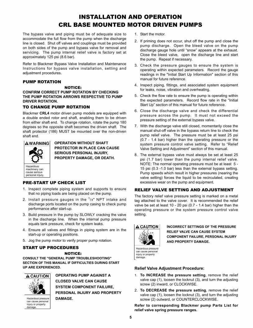
OPERATION WITHOUT GUARDS INPLACE CAN CAUSE SERIOUSPERSONAL INJURY, MAJORPROPERTY DAMAGE OR DEATH.
Hazardousmachinery cancause seriouspersonal injury.
INSTALLATION AND OPERATION CRL BASE MOUNTED MOTOR DRIVEN PUMPS
V-BELT DRIVEBlackmer also offers V-belt drive for CRL pumps. Forinstallation of Blackmer V-belt units, first mount the pump andthe motor base to the unit base. Do not fully tighten the motormounting bolts until properly installing and adjusting the beltsas follows:1. Wipe the cone surface of the pump QD hub (152A) and the
inside of the pump sheave hub with a clean clothmoistened with a light grade of machine oil. This will allowfor a more uniform draw and prevent the cone surfacesfrom “freezing” before being tightened.
2. With the shaft key (35) in place, align the key seat andslide the QD hub (152A) on the shaft, flange end first.Slide the large end of the sheave bore over the taper onthe QD hub. Insert the three sheave capscrews (152C)through the clearance holes in the sheave, and start theminto the tapped holes of the QD hub (152A). Repeat thisprocedure to assemble the motor QD hub (152E) andsheave (152D).
3. To install the belts (181), shorten the center distance of thedrive by moving the motor towards the pump, until the thebelts can be put on the sheaves (152 & 152D) withoutforcing.
4. Align the sheaves so that the faces are parallel, then snugup the sheave capscrews (152C & 152G).
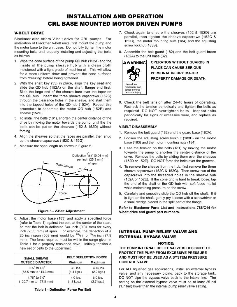
5. Measure the span length as shown in Figure 5.
Figure 5 - V-Belt Adjustment
6. Adjust the motor base (183) and apply a specified force(refer to Table 1) against the belt, at the center of the span,so that the belt is deflected 1/64 inch (0.04 mm) for everyinch (25.3 mm) of span. For example, the deflection of a20 inch span (508 mm) would be 20/64 or 5/16 inch (7.9mm). The force required must be within the range given inTable 1 for a properly tensioned drive. Initially tension anew set of belts to the upper limit.
7. Check again to ensure the sheaves (152 & 152D) areparallel, then tighten the sheave capscrews (152C &152G), the motor mounting nuts (184) and the adjustingscrew locknut (183B).
8. Assemble the belt guard (182) and the belt guard brace(182A) to the unit base (32).
9. Check the belt tension after 24-48 hours of operating.Recheck the tension periodically and tighten the belts asrequired. DO NOT overtighten belts. Inspect beltsperiodically for signs of excessive wear, and replace asrequired.
V-BELT DISASSEMBLY1. Remove the belt guard (182) and the guard base (182A). 2. Loosen the adjusting screw locknut (183B) on the motor
base (183) and the motor mounting nuts (184).3. Ease the tension on the belts (181) by moving the motor
towards the pump to shorten the center distance of thedrive. Remove the belts by sliding them over the sheaves(152D or 152E). DO NOT force the belts over the grooves.
4. To remove the sheave from the hub, first remove the threesheave capscrews (152C & 152G). Then screw two of thecapscrews into the threaded holes in the sheave hub(152A or 152E). If the cone grip is hard to break loose, tapthe end of the shaft or the QD hub with soft-faced malletwhile maintaining pressure on the screw.
5. Carefully and smoothly slide the QD hub off the shaft. If itis tight on the shaft, gently pry it loose with a screwdriver ora small wedge placed in the split part of the flange.
Refer to Blackmer Parts List and Instructions 786/C14 forV-belt drive and guard part numbers.
SMALL SHEAVE BELT DEFLECTION FORCEOUTSIDE DIAMETER Minimum Maximum
2.5" to 4.5" 3.0 lbs. 4.75 lbs.(63.5 mm to 114.3 mm) (1.4 kgs.) (2.2 kgs.)
4.75" to 7.0" 4.0 lbs. 6.0 lbs.(120.7 mm to 177.8 mm) (1.8 kgs.) (2.7 kgs.)
Table 1 - Deflection Force Per Belt
Deflection 1/64" (0.04 mm)per inch (25.3 mm)
of spanSpan Length
Force
INTERNAL PUMP RELIEF VALVE AND EXTERNAL BYPASS VALVE
NOTICE:THE PUMP INTERNAL RELIEF VALVE IS DESIGNED TOPROTECT THE PUMP FROM EXCESSIVE PRESSUREAND MUST NOT BE USED AS A SYSTEM PRESSURECONTROL VALVE.
For ALL liquefied gas applications, install an external bypassvalve, and any necessary piping, back to the storage tank.DO NOT pipe the bypass valve back to the intake line. Thesetting on the external bypass valve must be at least 25 psi(1.7 bar) lower than the internal pump relief valve setting.
5
The bypass valve and piping must be of adequate size toaccommodate the full flow from the pump when the dischargeline is closed. Shut off valves and couplings must be providedon both sides of the pump and bypass valve for removal andservicing. The pump internal relief valve is factory set atapproximately 125 psi (8.6 bar).
Refer to Blackmer Bypass Valve Installation and MaintenanceInstructions for bypass valve installation, setting andadjustment procedures.
PUMP ROTATION NOTICE:
CONFIRM CORRECT PUMP ROTATION BY CHECKINGTHE PUMP ROTATION ARROWS RESPECTIVE TO PUMPDRIVER ROTATION.TO CHANGE PUMP ROTATION Blackmer CRL4 motor driven pump models are equipped witha double ended rotor and shaft, enabling them to be drivenfrom either shaft end. To change rotation, rotate the pump 180degrees so the opposite shaft becomes the driven shaft. Theshaft protector (186) MUST be mounted over the non-drivenshaft end.
START UP PROCEDURESNOTICE:
CONSULT THE "GENERAL PUMP TROUBLESHOOTING"SECTION OF THIS MANUAL IF DIFFICULTIES DURING STARTUP ARE EXPERIENCED.
1. Start the motor.
2. If priming does not occur, shut off the pump and close thepump discharge. Open the bleed valve on the pumpdischarge gauge hole until “snow” appears at the exhaust.Close the bleed valve, open the discharge line and startthe pump. Repeat if necessary.
3. Check the pressure gauges to ensure the system isoperating within expected parameters. Record the gaugereadings in the "Initial Start Up Information" section of thismanual for future reference.
4. Inspect piping, fittings, and associated system equipmentfor leaks, noise, vibration and overheating.
5. Check the flow rate to ensure the pump is operating withinthe expected parameters. Record flow rate in the “InitialStart Up” section of this manual for future reference.
6. Close the discharge valve and check the differentialpressure across the pump. It must not exceed thepressure setting of the external bypass valve.
7. With the discharge valve still closed, momentarily close themanual shut-off valve in the bypass return line to check thepump relief valve. The pressure must be at least 25 psi(0.7 - 1.4 bar) higher than the operating pressure or thesystem pressure control valve setting. Refer to “ReliefValve Setting and Adjustment” section of this manual.
8. The external bypass valve must always be set at least 25psi (1.7 bar) lower than the pump internal relief valve.NOTE: The normal operating pressure must be at least 5 -15 psi (0.3 -1.0 bar) less than the external bypass setting.Pump speeds which result in higher pressures (nearing thevalve setting) forces the liquid to be recirculated, creatingexcessive wear on the pump and equipment.PRE-START UP CHECK LIST
1. Inspect complete piping system and supports to ensurethat no piping loads are being placed on the pump.
2. Install pressure gauges in the 1/4" NPT intake anddischarge ports located on the pump casing to check pumpperformance after start-up.
3. Build pressure in the pump by SLOWLY cracking the valvein the discharge line. When the internal pump pressureequals tank pressure, check for system leaks.
4. Ensure all valves and fittings in piping system are in thestart-up or operating positions.
5. Jog the pump motor to verify proper pump rotation.
INSTALLATION AND OPERATION CRL BASE MOUNTED MOTOR DRIVEN PUMPS
RELIEF VALVE SETTING AND ADJUSTMENTThe factory relief valve pressure setting is marked on a metaltag attached to the valve cover. It is recommended the reliefvalve be set at least 10 - 20 psi (0.7 - 1.4 bar) higher than theoperating pressure or the system pressure control valvesetting.
Hazardous pressurecan cause personalinjury or propertydamage.
INCORRECT SETTINGS OF THE PRESSURERELIEF VALVE CAN CAUSE SYSTEMCOMPONENT FAILURE, PERSONAL INJURYAND PROPERTY DAMAGE.
OPERATING PUMP AGAINST ACLOSED VALVE CAN CAUSESYSTEM COMPONENT FAILURE,PERSONAL INJURY AND PROPERTYDAMAGE.Hazardous pressure
can cause personalinjury or propertydamage.
Relief Valve Adjustment Procedure:1. To INCREASE the pressure setting, remove the relief
valve cap (1), loosen the locknut (3), and turn the adjustingscrew (2) inward, or CLOCKWISE.
2. To DECREASE the pressure setting, remove the reliefvalve cap (1), loosen the locknut (3), and turn the adjustingscrew (2) outward, or COUNTERCLOCKWISE.
Refer to corresponding Blackmer pump Parts List forrelief valve spring pressure ranges.
OPERATION WITHOUT SHAFTPROTECTOR IN PLACE CAN CAUSESERIOUS PERSONAL INJURY,PROPERTY DAMAGE, OR DEATH.
Hazardousmachinery cancause seriouspersonal injury.
INSTALLATION AND OPERATION - CRL TRUCK MOUNTED PUMPS
6
TRUCK MOUNTINGCRL pump models can be bolted to the truck frame or on asaddle hung below the frame, and MUST be adequatelysupported.Discontinued TCRLF4A pump models are designed to flangemount directly to bob tail or transport tank in combination witha commercial internal control valve. See Figure 6.PRE-INSTALLATION CLEANINGForeign matter entering the pump WILL cause extensivedamage. The supply tank and intake piping MUST be cleanedand flushed prior to pump installation and operation.LOCATION AND PIPINGAn improperly designed piping system or improper unitinstallation WILL significantly reduce pump performance andlife. Blackmer recommends the following piping system layoutand unit installation.1. When locating the pump on the tank, safety must be the
first consideration. Other considerations include length ofdrive line, accessibility for maintenance and convenienceof connections. See Figure 6.
2. The discharge hose and fittings must be large enough tominimize the pressure drop in the system. The lower thefriction loss, the higher the flow rate.
3. Use a 11/2" or 2" vapor return line for all transport loadingand unloading. Without a vapor return line, back pressurewill build up in the receiving tank and pressure will bereduced in the supply tank, resulting in reduced flow rateand fluid bypassing.
4. Keeping the liquefied gas systems full of liquid, even whenidle, will keep the O-rings from changing shape, shrinkingor super cooling. Evaporation of liquefied gas leaves anabrasive powder on the surface which can cause wear tothe pump, meter, and seals.
AUXILIARY INLET - DISCONTINUED TCRLF4APUMP MODELSThe auxiliary inlet port can be used as a fill connection forbottom loading of the tank by stationary pumps at the terminalor bulk plant. It can also be used as an auxiliary pump inlet,allowing the pump to unload another tank in an emergency. Tominimize vapor formation, the auxiliary intake line must be aslarge in diameter as the intake connection and as short aspossible. The line must be connected through a suitablestrainer, minimum 40 mesh. Reduce pump speed to amaximum 400 RPM when using the auxiliary inlet to reducecavitation.
PUMP DRIVE The pump may be driven by a power take-off through universaljoints. When using universal joints, a splined slip joint,properly lubricated, must be used on the connecting jack shaftto prevent end thrust on the pump shaft.
It is very important to install a proper drive line to avoidexcessive wear, vibration and noise (see Fig. 6 and Table 2).
General guidelines to follow for proper pump drive:
1. Do not use square slip joints.2. Use the least number of jack shafts as is practical.3. Use an even number of universal joints.4. The pump shaft and power take-off shaft must be parallel in
all respects. Use an angular level measuring device toensure the PTO and pump shaft are parallel to each other.The PTO shaft coming off at the transmission does notneed to be perfectly horizontal as long as the pump shaft isparallel in all respects to the PTO shaft.
5. The yokes of the universals at both ends of the jack shaftmust be parallel and in phase.
6. The maximum recommended angle between the jack shaftand the pump shaft is 15 degrees. Refer to Table 2.
Failure to follow any of these guidelines may result in a gallopor uneven turning of the pump rotor, which will in turn cause asurging vibration to the liquid stream and piping system.Contact the supplier of the drive line components for specificdesign assistance.
NOTICE:BLACKMER CO2 TRUCK PUMPS MUST ONLY BEINSTALLED IN SYSTEMS DESIGNED BY QUALIFIEDENGINEERING PERSONNEL. SYSTEM DESIGN MUSTCONFORM WITH ALL APPLICABLE REGULATIONSAND CODES AND PROVIDE WARNING OF ALLSYSTEM HAZARDS.
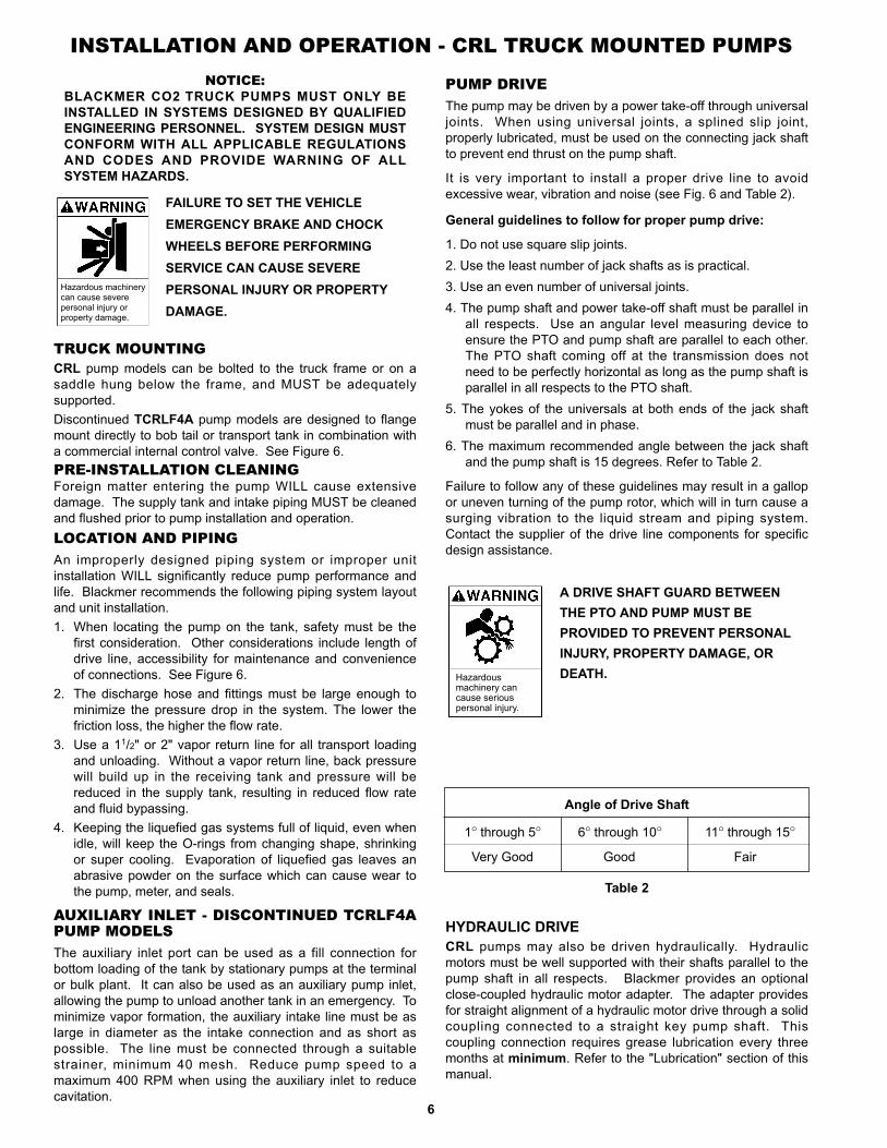
FAILURE TO SET THE VEHICLEEMERGENCY BRAKE AND CHOCKWHEELS BEFORE PERFORMINGSERVICE CAN CAUSE SEVEREPERSONAL INJURY OR PROPERTYDAMAGE.
Hazardous machinerycan cause severepersonal injury orproperty damage.
Table 2
Angle of Drive Shaft
1o through 5o 6o through 10o 11o through 15o
Very Good Good Fair
HYDRAULIC DRIVECRL pumps may also be driven hydraulically. Hydraulicmotors must be well supported with their shafts parallel to thepump shaft in all respects. Blackmer provides an optionalclose-coupled hydraulic motor adapter. The adapter providesfor straight alignment of a hydraulic motor drive through a solidcoupling connected to a straight key pump shaft. Thiscoupling connection requires grease lubrication every threemonths at minimum. Refer to the "Lubrication" section of thismanual.
Hazardousmachinery cancause seriouspersonal injury.
A DRIVE SHAFT GUARD BETWEENTHE PTO AND PUMP MUST BEPROVIDED TO PREVENT PERSONALINJURY, PROPERTY DAMAGE, ORDEATH.
INSTALLATION AND OPERATION - CRL TRUCK MOUNTED PUMPS
PRE-START UP CHECK LIST1. Install pressure gauges in the 1/4" NPT ports located on the
pump casing. These can be used to check the actual inletand discharge conditions after pump start-up.
7
2. Inspect complete piping system to ensure that no pipingloads are being placed on the pump.
3. Connect the hose to the receiving tank.
START UP PROCEDURESNOTICE:
CONSULT THE "GENERAL PUMP TROUBLESHOOTING"SECTION OF THIS MANUAL IF DIFFICULTIES DURINGSTART UP ARE EXPERIENCED.
1. Open the shut-off valve in the bypass return line.2. If the tank outlet valve is:
INTERNAL PUMP RELIEF VALVE AND EXTERNAL BYPASS VALVE
NOTICE:THE PUMP INTERNAL RELIEF VALVE IS DESIGNED TOPROTECT THE PUMP FROM EXCESSIVE PRESSUREAND MUST NOT BE USED AS A SYSTEM PRESSURECONTROL VALVE.For ALL liquefied gas applications, install an external bypassvalve, and any necessary piping, back to the tank. DO NOTpipe the bypass valve back to the intake line. The setting onthe external bypass valve must be at least 25 psi (1.7 bar)lower than the internal pump relief valve setting. The valveand piping must be of adequate size to accommodate the fullflow from the pump when the discharge line is closed. Thepump internal relief valve is factory set at approximately 125psi (8.6 bar).Refer to Blackmer Bypass Valve Installation and MaintenanceInstructions for bypass valve settings and adjustments.PUMP ROTATION
NOTICE:CONFIRM CORRECT PUMP ROTATION BY CHECKING THEPUMP ROTATION ARROWS RESPECTIVE TO PUMP DRIVERROTATION.
TO CHANGE PUMP ROTATION Blackmer CRL4 and discontinued TCRLF4A pump models areequipped with a double ended rotor and shaft, enabling themto be driven from either shaft end. To change rotation, rotatethe pump 180 degrees so that the opposite shaft becomes thedriven shaft. Mount the shaft protector (186) over the non-driven shaft end.
a. Lever Operated - Pull the control knob all the way out.Manually check the lever under the truck to see that it isin the completely OPEN position.
b. Discharge Pressure Operated - Keep the dischargeline valve closed. When pump is started, it will build upenough pressure to open the tank outlet valve. NOTE:This type of valve usually requires approximately 20 psi(1.4 bar) differential pressure to open andapproximately 15 psi (1.0 bar) differential pressure tokeep it open. If the piping is quite large, it may benecessary to restrict the discharge line shut-off valve inorder to maintain sufficient pressure to keep the tankoutlet valve open.
3. Start the pump. Confirm proper pump rotation by checkingthe pump rotation arrows.
4. Check the pump speed. Pump speed must never exceedthe recommended maximum. Refer to “Technical Data”section of this manual.
5. Check the pressure gauges and flowrate to ensure thesystem is operating within expected parameters. Recordthe gauge readings and flowrate in the "Initial Start UpInformation" section of this manual for future reference.
6. Inspect piping, fittings, and associated system equipmentfor leaks, noise, vibration and overheating.
7. Close the discharge valve and check the differentialpressure across the pump. It must not exceed thepressure setting of the external bypass valve.
8. With the discharge valve still closed, momentarily close themanual shut-off valve in the bypass return line to check thepump relief valve. The differential pressure will beapproximately 100 psi (6.9 bar).
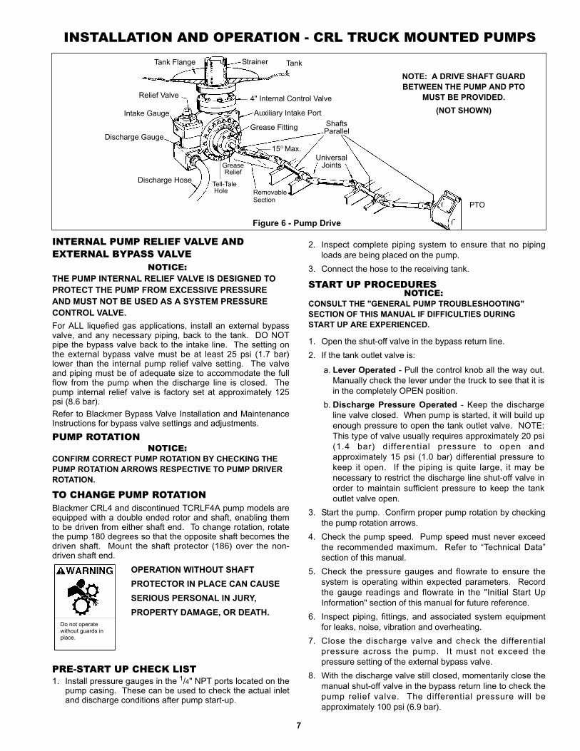
Figure 6 - Pump Drive
TankTank Flange
Relief Valve
Intake Gauge
Discharge Gauge
Discharge Hose
Strainer
4" Internal Control Valve
Auxiliary Intake Port
Grease Fitting
RemovableSection
GreaseRelief
Tell-TaleHole
ShaftsParallel
15oMax.Universal
Joints
PTO
NOTE: A DRIVE SHAFT GUARDBETWEEN THE PUMP AND PTO
MUST BE PROVIDED.(NOT SHOWN)
OPERATION WITHOUT SHAFTPROTECTOR IN PLACE CAN CAUSESERIOUS PERSONAL IN JURY,PROPERTY DAMAGE, OR DEATH.
Do not operatewithout guards inplace.

8
FAILURE TO SET THE VEHICLEEMERGENCY BRAKE AND CHOCKWHEELS BEFORE PERFORMINGSERVICE CAN CAUSE SEVEREPERSONAL INJURY OR PROPERTYDAMAGE.
Hazardous machinerycan cause severepersonal injury orproperty damage.
Hazardous or toxicfluids can causeserious injury.
IF PUMPING HAZARDOUS FLUIDSSYSTEM MUST BE FLUSHED PRIORTO PERFORMING SERVICE.
NOTICE:MAINTENANCE SHALL BE PERFORMED BY QUALIFIEDTECHNICIANS ONLY, FOLLOWING THE APPROPRIATEPROCEDURES AND WARNINGS AS PRESENTED INTHIS MANUAL.
INSTALLATION AND OPERATION - CRL TRUCK MOUNTED PUMPS
MAINTENANCE
Hazardousmachinery cancause seriouspersonal injury.
FAILURE TO DISCONNECT ANDLOCKOUT ELECTRICAL POWERBEFORE ATTEMPTING MAINTENANCECAN CAUSE SERIOUS PERSONALINJURY OR DEATH.
DO NOT ATTEMPT TO OPEN THE PUMPUNTIL YOU HAVE BLED OFF THEPRESSURE. ON SYSTEMS WITHMETERS, THE DIFFERENTIAL VALVEWILL KEEP LIQUID UNDER PRESSUREIN THE PUMP, METER AND PIPINGEVEN WHEN THE HOSE IS EMPTIED.
Hazardous pressurecan cause personalinjury or propertydamage.
FAILURE TO DISCONNECT ANDLOCKOUT ELECTRICAL POWERBEFORE ATTEMPTING MAINTENANCECAN CAUSE SHOCK, BURNS ORDEATH.Hazardous voltage.
Can shock, burn or cause death.
10.The external bypass valve must always be set at least 25psi (1.7 bar) lower than the internal pump relief valve.NOTE: The normal operating pressure must be at least 5 - 15 psi (0.3 - 1.0 bar) less than the external bypasssetting. Pump speeds which result in higher pressures(near the valve setting) forces the liquid to be recirculated,creating excessive wear on the pump and equipment.
RELIEF VALVE SETTING AND ADJUSTMENTThe pump internal relief valve factory pressure setting ismarked on a metal tag attached to the valve cover. The reliefvalve must be set at least 10 - 20 psi (0.7 -1.4 bar) higher thanthe operating pressure or the system pressure control valvesetting.Relief Valve Adjustment Procedure:1. To INCREASE the pressure setting, remove the relief
valve cap (1), loosen the locknut (3), and turn the adjustingscrew (2) inward, or CLOCKWISE.
2. To DECREASE the pressure setting, remove the reliefvalve cap (1), loosen the locknut (3), and turn the adjustingscrew (2) outward, or COUNTERCLOCKWISE.
PUMP SPEEDPTO and hydraulically driven units MUST contain speedcontrol devices to prevent pump speeds above the maximumRPM specifications, regardless of the truck engine unloadingspeeds. Should fluid delivery be appreciably less thanexpected, see the "General Pump Troubleshooting" section.
DISCONNECTING FLUID ORPRESSURE CONTAINMENTCOMPONENTS DURING PUMPOPERATION CAN CAUSE SERIOUSPERSONAL INJURY, DEATH OR MAJORPROPERTY DAMAGE.
Hazardous pressurecan cause personalinjury or propertydamage.
LUBRICATIONBall bearings and hydraulic motor adapter couplings (ifequipped) must be lubricated every three months at aminimum. More frequent lubrication may be required,depending on the application and operating conditions.Recommended Grease:Exxon® - RONNEX MP Grease; Mobil® MOBILITH AW-2 (64353-6) Grease, or equivalentLithium grease.Greasing Procedure:1. Remove the grease relief fittings (76A) from the bearing
covers (27) or hydraulic motor adapter (135).2. SLOWLY apply grease with a hand gun until grease begins
to escape from the grease relief fitting port. Discardexcess grease in accordance with the proper codes and regulations.
3. Replace the grease relief fittings (76A).DO NOT overgrease pump bearings. While it is normal forsome grease to escape from the grease tell-tale hole afterlubrication, excessive grease can cause mechanical sealfailure. The tell-tale hole is located in the head (20) betweenthe bearing (24) and the mechanical seal (153).
INCORRECT SETTINGS OF THE PRESSURERELIEF VALVE CAN CAUSE SYSTEMCOMPONENT FAILURE, PERSONAL INJURYAND PROPERTY DAMAGE.
Hazardous pressurecan cause personalinjury or propertydamage.

PUMP DISASSEMBLY
NOTICE:FOLLOW ALL HAZARD WARNINGS ANDINSTRUCTIONS PROVIDED IN THE "MAINTENANCE"SECTION OF THIS MANUAL.
1. Drain and relieve pressure from the pump and system asrequired.
2. Starting on the inboard (driven) end of the pump, clean thepump shaft thoroughly, making sure the shaft is free ofnicks and burrs. This wil l prevent damage to themechanical seal when the inboard head assembly isremoved.
3. Remove the inboard bearing cover capscrews (28) andslide the inboard bearing cover (27) and gasket (26) off theshaft. Discard the bearing cover gasket.
4. Remove the outboard bearing cover capscrews (28) andslide the outboard bearing cover (27) and gasket (26) offthe shaft. Discard the bearing cover gasket.
5. To remove locknuts and lockwashers (24A and 24B):a. Bend up the engaged lockwasher tang and rotate the
locknut (24A)counterclockwise to remove it from theshaft
MAINTENANCE
9
VANE REPLACEMENT
NOTICE:MAINTENANCE SHALL BE PERFORMED BY QUALIFIEDTECHNICIANS ONLY, FOLLOWING THE APPROPRIATEPROCEDURES AND WARNINGS AS PRESENTED INTHIS MANUAL.1. Drain and relieve pressure from the pump and system as
required.2. Remove the head assembly from the outboard (non-
driven) side of the pump according to steps 4 - 7 in the"Pump Disassembly" section of this manual.
3. Turn the shaft by hand until a vane (14) comes to the top,(12 o'clock) position, of the rotor. Remove the vane.
4. Install a new vane (14), ensuring that the rounded edge isUP, and the relief grooves are facing towards the directionof rotation. See Figure 7.
5. Repeat steps 3 and 4 until all vanes have been replaced.6. Reassemble the pump according to the "Pump Assembly."
section of this manual.
Figure 7 - Vane Installation
b. Slide the lockwasher (24B) off the shaft. Inspect thelockwasher for damage and replace as required.
c. Repeat steps a and b on the opposite shaft end.
6. Remove the head capscrews (21) and carefully pry thehead (20) away from the casing (12).
7. Slide the head (20) off the shaft. The head O-ring (72),disc (71), bearing (24), and mechanical seal (153) willcome off with the head assembly. Remove and discard thehead O-ring.
a. Remove the four disc machine screws and lockwashers(71A & 71B) to release the disc (71) from the head (20).
b. Carefully pull the rotating seal assembly, consisting ofseal jacket (153C), rotating seal face and rotating O-ring (153B & 153E) from the head (20). Remove anddiscard the rotating O-ring.
c. Pull the bearing (24) from the housing in the head (20).d. To remove the mechanical seal stationary seat (153A),
use the blunt end of a screw driver to gently push thebackside of the stationary seat from the head. Place acloth under the seal to avoid damage. Be careful not tocontact the polished face of the seal during removal.Remove and discard mechanical seal stationary O-ring.
8. Carefully pull the rotor and shaft (13) from the casing (12).While one hand is pulling the shaft, cup the other handunderneath the rotor to prevent the vanes (14) and pushrods (77) from falling out. Carefully set the rotor and shaft(13) aside for future vane replacement and reassembly.
NOTICE:THE ROTOR AND SHAFT WEIGHS APPROXIMATELY 69POUNDS (31KG). BE CAREFUL NOT TO PINCH THEHAND UNDER THE ROTOR AND SHAFT WHENREMOVING FROM THE CASING.
9. Lay the pump flat with the remaining head (20) facingupward to remove the head assembly, mechanical seal(153) and disc (71) from the outboard side of the pump, asinstructed in steps 6 - 7 above.
10. If necessary, remove the liner (41) by tapping around theoutside diameter of the liner with a hard wood drift and ahammer until it is driven from the casing (12).
PUMP ASSEMBLYBefore reassembling the pump, inspect all componentparts for wear or damage, and replace as required. Washout the bearing/seal recess of the head and remove anyburrs or nicks from the rotor and shaft. Remove anyburrs from the liner.
Reassemble the OUTBOARD side of the pump first:
1. Apply a small amount of grease to the liner key (74) to holdthe key in place during liner installation. Install the linerkey in groove of the liner before starting liner into pumpcasing (12).
MAINTENANCE
10
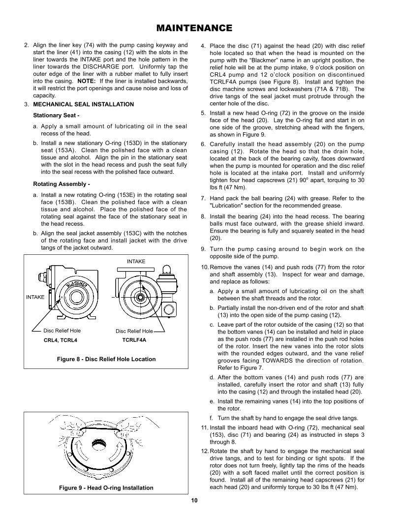
Figure 8 - Disc Relief Hole Location
4. Place the disc (71) against the head (20) with disc reliefhole located so that when the head is mounted on thepump with the “Blackmer” name in an upright position, therelief hole will be at the pump intake, 9 o’clock position onCRL4 pump and 12 o’clock position on discontinuedTCRLF4A pumps (see Figure 8). Install and tighten thedisc machine screws and lockwashers (71A & 71B). Thedrive tangs of the seal jacket must protrude through thecenter hole of the disc.
5. Install a new head O-ring (72) in the groove on the insideface of the head (20). Lay the O-ring flat and start in onone side of the groove, stretching ahead with the fingers,as shown in Figure 9.
6. Carefully install the head assembly (20) on the pumpcasing (12). Rotate the head so that the drain hole,located at the back of the bearing cavity, faces downwardwhen the pump is mounted for operation and the disc reliefhole is located at the intake port. Install and uniformlytighten four head capscrews (21) 90o apart, torquing to 30lbs ft (47 Nm).
7. Hand pack the ball bearing (24) with grease. Refer to the"Lubrication" section for the recommended grease.
8. Install the bearing (24) into the head recess. The bearingballs must face outward, with the grease shield inward.Ensure the bearing is fully and squarely seated in the head(20).
9. Turn the pump casing around to begin work on theopposite side of the pump.
10.Remove the vanes (14) and push rods (77) from the rotorand shaft assembly (13). Inspect for wear and damage,and replace as follows:a. Apply a small amount of lubricating oil on the shaft
between the shaft threads and the rotor.b. Partially install the non-driven end of the rotor and shaft
(13) into the open side of the pump casing (12).c. Leave part of the rotor outside of the casing (12) so that
the bottom vanes (14) can be installed and held in placeas the push rods (77) are installed in the push rod holesof the rotor. Insert the new vanes into the rotor slotswith the rounded edges outward, and the vane reliefgrooves facing TOWARDS the direction of rotation.Refer to Figure 7.
d. After the bottom vanes (14) and push rods (77) areinstalled, carefully insert the rotor and shaft (13) fullyinto the casing (12) and through the installed head (20).
e. Install the remaining vanes (14) into the top positions ofthe rotor.
f. Turn the shaft by hand to engage the seal drive tangs.11. Install the inboard head with O-ring (72), mechanical seal
(153), disc (71) and bearing (24) as instructed in steps 3through 8.
12.Rotate the shaft by hand to engage the mechanical sealdrive tangs, and to test for binding or tight spots. If therotor does not turn freely, lightly tap the rims of the heads(20) with a soft faced mallet until the correct position isfound. Install all of the remaining head capscrews (21) foreach head (20) and uniformly torque to 30 lbs ft (47 Nm).Figure 9 - Head O-ring Installation
2. Align the liner key (74) with the pump casing keyway andstart the liner (41) into the casing (12) with the slots in theliner towards the INTAKE port and the hole pattern in theliner towards the DISCHARGE port. Uniformly tap theouter edge of the liner with a rubber mallet to fully insertinto the casing. NOTE: If the liner is installed backwards,it will restrict the port openings and cause noise and loss ofcapacity.
3. MECHANICAL SEAL INSTALLATION
Stationary Seat -
a. Apply a small amount of lubricating oil in the sealrecess of the head.
b. Install a new stationary O-ring (153D) in the stationaryseat (153A). Clean the polished face with a cleantissue and alcohol. Align the pin in the stationary seatwith the slot in the head recess and push the seat fullyinto the seal recess with the polished face outward.
Rotating Assembly -
a. Install a new rotating O-ring (153E) in the rotating sealface (153B). Clean the polished face with a cleantissue and alcohol. Place the polished face of therotating seal against the face of the stationary seat inthe head recess.
b. Align the seal jacket assembly (153C) with the notchesof the rotating face and install jacket with the drivetangs of the jacket outward.
CRL4, TCRL4 TCRLF4A
INTAKE
INTAKE
Disc Relief Hole Disc Relief Hole

MAINTENANCE
11
Figure 10 - Locknut Adjustment
13.LOCKNUT ADJUSTMENTIt is important that the bearing locknuts (24A) andlockwashers (24B) be installed and adjusted properly.Overtightening locknuts can cause bearing (24) failure or abroken lockwasher tang. Loose locknuts will allow the rotorto shift against the discs (71), causing wear. See Figure 10.a. On both ends of the pump shaft, install a lockwasher
(24B) with the tangs facing outward, followed by alocknut (24A) with the tapered end inward. Ensure theinner tang "A" of the lockwasher is located in the slot inthe shaft threads, bending it slightly, if necessary.
b. Tighten both locknuts (24A) to ensure that the bearings(24) are bottomed in the head recess. DO NOT over-tighten and bend or shear the lockwasher inner tang.
c. Loosen both locknuts (24A) one complete turn.d. Tighten one locknut (24A) until a slight rotor drag is felt
when turning the shaft by hand.e. Back off the locknut (24A) the width of one lockwasher
tang "B". Secure the locknut by bending the closestaligned lockwasher tang into the slot in the locknut. Thepump must turn freely when rotated by hand.
OPERATION WITHOUT GUARDS INPLACE CAN CAUSE SERIOUSPERSONAL INJURY, PROPERTYDAMAGE, OR DEATH.
Do not operatewithout guardin place.
f. Tighten the opposite locknut (24A) by hand until it issnug against the bearing (24). Then, using a spannerwrench, tighten the nut the width of one lockwashertang. Tighten just past the desired tang, then back offthe nut to align the tang with the locknut slot. Securethe nut by bending the aligned lockwasher tang into theslot in the locknut. The pump must continue to turnfreely when rotated by hand.
g. To check adjustment, grasp the locknut (24A) andlockcollar (24B) with fingers and rotate back and forth.If this cannot be done, one or both locknuts are too tightand must be alternately loosened one stop at a time(.001" - 25 microns). Begin by loosening the locknutadjusted last.
14. Inspect the grease seal (104) for wear or damage andreplace as required. Grease the outside diameter of thegrease seal and push it into the inboard bearing cover (27)with the lip of the seal inward.
15.Attach a new bearing cover gasket (26) and the bearingcover (27) to the inboard head (20). Make sure the greasefittings (76) are accessible. Install and torque the bearingcover capscrews (28) to 30 lbs ft (47 Nm).
16. Install the grease seal (104) in the outboard bearing cover(27) as instructed in step 14.
17.Attach a new bearing cover gasket (26) and the outboardbearing cover (27) to the outboard head (20). Make surethe grease fittings (76) are accessible. Install and torquethe bearing cover capscrews (28) to 30 lbs ft (47 Nm).
18.Attach the shaft protector (186) to the non-driven shaft end.
GENERAL PUMP TROUBLESHOOTINGNOTICE:
MAINTENANCE SHALL BE PERFORMED BY QUALIFIED TECHNICIANS ONLY, FOLLOWINGTHE APPROPRIATE PROCEDURES AND WARNINGS AS PRESENTED IN THIS MANUAL.
SYMPTOM PROBABLE CAUSE
Pump Not Priming 1. Pump not wetted.2. Worn vanes.3. Internal control or inlet valve closed.4. Strainer clogged.5. Inlet line or valves clogged or too restrictive.6. Broken drive train (truck mounted pumps).7. Pump vapor-locked.8. Pump speed too low for priming.9. Relief valve partially open, worn or not seating properly.
Pump Troubleshooting continued on back page.
GENERAL PUMP TROUBLESHOOTING
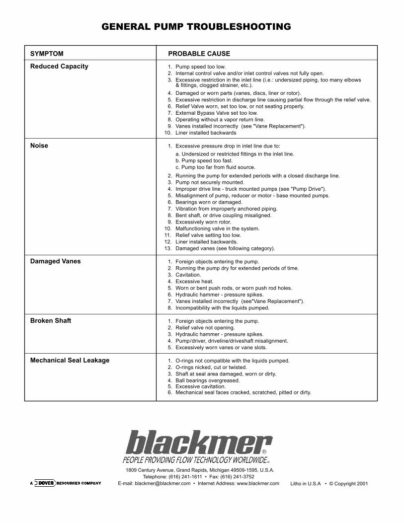
SYMPTOM PROBABLE CAUSE
Reduced Capacity 1. Pump speed too low.2. Internal control valve and/or inlet control valves not fully open.3. Excessive restriction in the inlet line (i.e.: undersized piping, too many elbows
& fittings, clogged strainer, etc.).4. Damaged or worn parts (vanes, discs, liner or rotor).5. Excessive restriction in discharge line causing partial flow through the relief valve.6. Relief Valve worn, set too low, or not seating properly.7. External Bypass Valve set too low.8. Operating without a vapor return line.9. Vanes installed incorrectly (see "Vane Replacement").
10. Liner installed backwards
Noise 1. Excessive pressure drop in inlet line due to: a. Undersized or restricted fittings in the inlet line.b. Pump speed too fast.c. Pump too far from fluid source.
2. Running the pump for extended periods with a closed discharge line.3. Pump not securely mounted.4. Improper drive line - truck mounted pumps (see "Pump Drive").5. Misalignment of pump, reducer or motor - base mounted pumps.6. Bearings worn or damaged.7. Vibration from improperly anchored piping.8. Bent shaft, or drive coupling misaligned.9. Excessively worn rotor.
10. Malfunctioning valve in the system.11. Relief valve setting too low.12. Liner installed backwards.13. Damaged vanes (see following category).
Damaged Vanes 1. Foreign objects entering the pump.2. Running the pump dry for extended periods of time.3. Cavitation.4. Excessive heat.5. Worn or bent push rods, or worn push rod holes.6. Hydraulic hammer - pressure spikes.7. Vanes installed incorrectly (see"Vane Replacement").8. Incompatibility with the liquids pumped.
Broken Shaft 1. Foreign objects entering the pump.2. Relief valve not opening.3. Hydraulic hammer - pressure spikes.4. Pump/driver, driveline/driveshaft misalignment.5. Excessively worn vanes or vane slots.
Mechanical Seal Leakage 1. O-rings not compatible with the liquids pumped.2. O-rings nicked, cut or twisted.3. Shaft at seal area damaged, worn or dirty.4. Ball bearings overgreased.5. Excessive cavitation.6. Mechanical seal faces cracked, scratched, pitted or dirty.
1809 Century Avenue, Grand Rapids, Michigan 49509-1595, U.S.A.Telephone: (616) 241-1611 • Fax: (616) 241-3752
E-mail: [email protected] • Internet Address: www.blackmer.com Litho in U.S.A • © Copyright 2001
Related Documents


