BL-Series Intelligent Data/Fax Modem User Guide

Welcome message from author
This document is posted to help you gain knowledge. Please leave a comment to let me know what you think about it! Share it to your friends and learn new things together.
Transcript

BL-SeriesIntelligent Data/Fax Modem
User Guide

User Guide
88312100 Revision A
MultiModemII Models:MT2834BL/MT2834BLI/MT2834BLK
MT1932BL/MT1932BLI/MT1932BL-MacMT1432BL/MT1432BLI/MT1432BLK
This publication may not be reproduced, in whole or in part, without prior expressed writtenpermission from Multi-Tech Systems, Inc.
All rights reserved.
Copyright 1999 ©, by Multi-Tech Systems, Inc.
Multi-Tech Systems, Inc. makes no representations or warranties with respect to the contents hereofand specifically disclaims any implied warranties of merchantability or fitness for any particularpurpose. Furthermore, Multi-Tech Systems, Inc. reserves the right to revise this publication and tomake changes from time to time in the content hereof without obligation of Multi-Tech Systems, Inc.to notify any person or organization of such revisions or changes.
Record of Revisions
A (6/1/99) Manual formatted for electronic distribution. All pages at Revision A.
Trademarks of Multi-Tech Systems, Inc. are as follows:
MultiModemII, Multi-Tech and the Multi-Tech logo.
MNP, Microcom Network Protocol is a trademark of Microcom Inc.
AS/400 and System3x is a trademark of IBM.
Macintosh is a trademark of Apple Computer Inc.
Unix is a trademark of X/Open Co. Ltd.
Windows® and Windows® 95 are registered trademarks of Microsoft
All other brands and product names mentioned in this publication are trademarks or registeredtrademarks of their respective companies.
Multi-Tech Systems, Inc.2205 Woodale Drive
Mounds View, Minnesota 55112 U.S.A.(612) 785-3500 or (800) 328-9717
U. S. FAX 612-785-9874Fax-Back Service 612-717-5888
Technical Support (800) 972-2439BBS (612) 785-3702 or (800) 392-2432
Internet Address: http://www.multitech.comTechnical Writer: [email protected]

Contents
Chapter 1 - Introduction and Description
1.1 Introduction ...................................................................................................................................... 81.2 How To Use This Manual ................................................................................................................. 81.3 Modem Features ............................................................................................................................. 10
1.3.1 2834 Series Features ................................................................................................................ 101.3.2 1932 Series Features ................................................................................................................ 101.3.3 1432 Series Features ................................................................................................................ 11
1.4 Fax Features ................................................................................................................................... 111.5 Technical Specifications .................................................................................................................. 121.6 Power .............................................................................................................................................. 161.7 Modem LED Indicators .................................................................................................................... 161.8 Controls on PC Board ..................................................................................................................... 17
Chapter 2 - Installation and Connection
2.1 What is in Your Modem Package? .................................................................................................. 202.2 Installation ....................................................................................................................................... 21
2.2.1 Safety Warnings ........................................................................................................................ 212.2.2 Installation Procedure ............................................................................................................... 212.2.3 Cabling Procedure (MT1432BL/BLI, MT1932BL/BLI, and MT2834BL/BLI) .............................. 212.2.4 Cabling Procedure (MT1432BLK and MT2834BLK) ................................................................. 23
2.3 Loading Trio DataFAX Software ...................................................................................................... 242.4 Is Your Modem Ready for Use? ...................................................................................................... 26
Chapter 3 - Software Configuration and Modem Basics
3.1 Introduction ...................................................................................................................................... 283.2 Serial Port Limitations ..................................................................................................................... 28
3.2.1 How Can You Identify Your UART Type? .................................................................................. 283.2.2 The 16550 UART and Windows 3.1 .......................................................................................... 29
3.3 Configuring Your Software ............................................................................................................... 293.3.1 ConfiguringSoftware for Your Modem ....................................................................................... 29
3.4 PC Initialization Strings ................................................................................................................... 303.4.1 Changing Default Parameters ................................................................................................... 303.4.2 Other Parameters ..................................................................................................................... 30
3.5 Macintosh Initialization .................................................................................................................... 313.6 Configuring Software for Your Computer ......................................................................................... 31
3.6.1 Configuring Software for the Remote System ........................................................................... 313.6.2 Terminal Emulation ................................................................................................................... 313.6.3 File Transfer Protocols .............................................................................................................. 32
3.7 When to Disable Data Compression ............................................................................................... 323.7.1 Disabling Error Correction ......................................................................................................... 32
3.8 Modem Basics ................................................................................................................................. 333.8.1 Simple Operations .................................................................................................................... 33
3.9 The Answer/Originate - Voice/Data Toggle Switch .......................................................................... 33
iii
Chapter 4 - Manual Dial and Automatic Answer
4.1 Introduction ...................................................................................................................................... 364.2 Dialing/On-Line/Answering .............................................................................................................. 364.3 Automatic Leased Line Restoral Operation ..................................................................................... 374.4 Manual Dial Backup Call Termination .............................................................................................. 374.5 Dial Backup and Leased Line Restoral ........................................................................................... 374.6 Dial-Up Operation ............................................................................................................................ 384.7 Manual Call Origination ................................................................................................................... 384.8 Automatic Answering ....................................................................................................................... 394.9 Manual Answering ........................................................................................................................... 394.10 Handshaking Details ....................................................................................................................... 404.11 Call Termination ............................................................................................................................... 40
Chapter 5 - Command Mode
5.1 Introduction ...................................................................................................................................... 425.1.1 AT Command Editing ................................................................................................................ 425.1.2 Functional Modes ...................................................................................................................... 43
5.2 Summary of AT Commands............................................................................................................. 445.3 Result Codes ................................................................................................................................... 475.4 Dialing Commands .......................................................................................................................... 49
5.4.1 Dialing Action Commands ......................................................................................................... 495.4.2 Dial Modifier Commands ........................................................................................................... 505.4.3 Phone Number Memory Commands......................................................................................... 535.4.4 Configuration and Default Storage Commands ........................................................................ 545.4.5 Command Response (Result Code) Commands ...................................................................... 565.4.6 Phone Line Conditioning Commands ........................................................................................ 585.4.7 RS-232C Interface Control Commands .................................................................................... 615.4.8 Error Correction Commands ..................................................................................................... 635.4.9 Flow Control Commands .......................................................................................................... 665.4.10 Compression, Error Correction, Flow Control, Pass-Through and Pacing Commands ............ 695.4.11 Speed Conversion Commands ................................................................................................. 705.4.12 Immediate Action Commands ................................................................................................... 735.4.13 Line Probe Commands (2834 Series only) ............................................................................... 75
Chapter 6 - S-Registers
6.1 Introduction ...................................................................................................................................... 786.2 Reading and Assigning S-Register Values ...................................................................................... 85
6.2.1 Examples of Assigning Values .................................................................................................. 856.2.2 Examples of Reading Values .................................................................................................... 85
6.3 AT Command and S-Register Summary ......................................................................................... 86
Chapter 7 - Callback Security and Remote Configuration
7.1 Introduction ...................................................................................................................................... 887.2 Callback Feature Description .......................................................................................................... 887.3 Remote Configuration Description ................................................................................................... 89
7.3.1 Initial Setup Procedures for Callback and Remote Configuration. ............................................ 897.3.2 Remote Configuration Procedures ............................................................................................ 92
7.4 Remote Configuration and Callback Security AT Commands ......................................................... 937.5 Remote Configuration/Callback Security S-Registers ..................................................................... 95
iv
Chapter 8 - Modem Testing
8.1 Introduction ...................................................................................................................................... 988.2 Local Analog Loopback Test/V.54 Loop 3 ........................................................................................ 998.3 Digital Loopback Test/V.54 Loop 2 (Local/Manual) .......................................................................... 1008.4 Digital Loopback Test/V.54 Loop 2 (Remote/Automatic) ................................................................. 1018.5 Back-to-Back Test ........................................................................................................................... 1028.6 Synchronous Mode Testing ............................................................................................................. 1038.7 Local Analog Loopback Test (Synchronous Mode) ......................................................................... 1038.8 Digital Loopback Test (Local/Manual) (Synchronous Mode) ........................................................... 1048.9 Digital Loopback Test (Remote/Automatic) (Synchronous Mode) ................................................... 105
Chapter 9 - DIP-Switch Settings
9.1 Introduction ...................................................................................................................................... 1089.2 DIP-Switch Option Settings ............................................................................................................. 1099.3 Speaker Volume Control ................................................................................................................. 1149.4 Recording Option Configurations .................................................................................................... 115
Chapter 10 - Warranty, Service and Tech Support
10.1 Introduction ...................................................................................................................................... 11810.2 Limited Warranty ............................................................................................................................. 118
10.2.1 On-line Warranty Registration ................................................................................................... 11810.3 Tech Support ................................................................................................................................... 119
10.3.1 Recording Modem Information .................................................................................................. 11910.4 Service ............................................................................................................................................ 11910.5 The Multi-Tech BBS......................................................................................................................... 120
10.5.2 Upgrading the MultiModem ...................................................................................................... 12110.5.3 Using FlashPro to Upgrade Modem Firmware .......................................................................... 121
10.6 About Multi-Tech’s Internet Presence .............................................................................................. 12110.7 About the Multi-Tech Fax-Back Service .......................................................................................... 12110.8 About Ordering Accessories ............................................................................................................ 122
Appendixes
Appendix A - Troubleshooting ....................................................................................................................... 124Appendix B - ASCII Character Code/Hex/Decimal Conversion Chart .......................................................... 129Appendix C - Dial Pulse and Tone-Dial Frequencies .................................................................................... 130Appendix D - Command Summary ............................................................................................................... 131Appendix E - DIP-Switch Summary ............................................................................................................. 140Appendix F - S-Register Summary .............................................................................................................. 143Appendix G - Result Code Summary ........................................................................................................... 145Appendix H - V.25bis Operation ................................................................................................................... 147Appendix I - MultiModemBL Cables ............................................................................................................. 154Appendix J - RS-232C Interface Specifications ........................................................................................... 156Appendix K - Regulatory Information ........................................................................................................... 160
Index
v

vi

Chapter 1 - Introduction and Description

8
MultiModemBL User Guide
1.1 Introduction
Welcome to the world of data communications. You have acquired one of the finest intelligentdesktop data/fax modems available today, the MultiModemII BL series modem, from Multi-TechSystems. This User Guide covers various models within the BL series, and unless otherwise noted,all content should be considered relevant to all models.
Your MultiModem provides data communication at the following rates:
�����
������ ������
������� ������
������ ������
���� ����
���� � ���� ��� ���������� !" !��#
������ � ���� ��� � !����� " !��#
���� � �� ��� � !��#
*Note enhancements on V.34 code (33.6K/31.2K) is awaiting formal ITU approval; the ITU study group 14 has agreed onthe technical side of the proposal, with formal approval expected at the next ITU meeting in Geneva.
The MultiModem also provides other prevalent data communications standards and includes dialbackup with automatic lease line restoration, adaptive protocol enhancing used in typical Unix® batchfile transfers and support for IBM's AS/400TM and WindowsTM environments.
1.2 How To Use This ManualThis manual is divided into ten chapters. While viewing in Acrobat ReaderTM you can click on bluetext to jump to the section of the manual it references. Red, bold text indicates a hyperlink to theInternet. If you have a Web browser active on your system, click on these text links to open thebrowser and go to the referenced site. The information contained in each chapter and appendix is asfollows:
Chapter 1 - Introduction and Description
This chapter begins with a short introduction, followed by a guide (which you are now reading) to theuse of this manual. There is a discussion about what components you can expect in your modempackage. We then provide a more detailed description of the modem, including the modem’stechnical specifications. Chapter 1 includes sections covering power, LED indicators and a briefsummary of PC board controls. (Chapter 9 covers switch settings more thoroughly.)
Chapter 2 - Installation and Connection
Chapter 2 covers the procedure for connecting the modem to your computer and to the phone line.Details are given, supported by illustrations on the modem's back panel connections as a guide toinstall your modem to the point of operation. In addition, this chapter guides you through theinstallation of Trio, the communications software included with your modem.
Chapter 3 - Software Configuration and Modem Basics
Chapter 3 documents communication software configuration recommended specifically for theMultiModem. Other issues covered include setting up initialization strings, changing defaultparameters, configuring software for the remote system and file transfer protocols.
Chapter 4 - Manual Dial and Automatic Answer
Chapter 4 covers some modem operations, but delays discussion on Command Mode operation untilChapter 5. Automatic Leased Line Restoration, Dial backup, Manual Dial Mode, and Answer Modeoperation are covered in detail, as well as the handshaking procedures employed between twomodems in an auto-answer application.

9
Chapter 1 - Introduction and Description
Chapter 5 - AT Command Mode Operation
Chapter 5 may be the most important chapter of this manual. It begins with an introduction anddiscussion on Command Mode fundamentals. A flow chart is provided to illustrate Command Modeand On-Line Mode operation and the methods used in each mode. Next, there is a summary of themodem’s commands and responses. We then go into a detailed explanation of each modemcommand, providing examples where applicable.
Chapter 6 - S-Registers
Chapter 6 covers the modem's S-Registers, which enable the user to establish, read, and modifyvarious modem options. All of the S-Registers are charted and explained, followed by instructions onaccessing the S-Registers and reading or changing their values.
Chapter 7 - Callback and Remote Configuration
Chapter 7 documents instructions on how to operate the modem's Callback and RemoteConfiguration features; and the usage of LOGIN Passwords, Set-Up Passwords and Remote EscapeCharacters as network management tools.
Chapter 8 - Testing Your Modem
Chapter 8 covers the modem's built-in test features. These are: Power-on Self Test, Back-To-BackTest, Local Analog Loopback, Digital Loopback and Remote Digital Loopback Tests. We haveincluded a description of each test and how to use each test procedure.
Chapter 9 - DIP-Switches
Chapter 9 covers the modem’s printed-circuit board options. Sixteen DIP-Switch settings and themodem's speaker volume control are explained in detail, including all default settings.
Chapter 10 - Warranty, Service & Technical Support
Chapter 10 provides statements on your five-year warranty, instructions for getting modems servicedat the factory, the procedure for downloading firmware upgrades via FlashROM, information aboutMulti-Tech's Bulletin Board Service (BBS), a section on receiving technical support via theCompuServe/Internet forums and information on Multi-Tech's Fax-Back Service.
Appendixes
There are also several appendices at the end of this manual, most of which repeat informationcontained in the chapters, but in a more condensed form. These appendices can be used as a quickreference.
Appendix A - TroubleshootingAppendix B - ASCII/HEX/Decimal Conversion ChartAppendix C - Pulse Dial and Tone-Dial FrequenciesAppendix D - AT Command SummaryAppendix E - DIP Switch SummaryAppendix F - S-Register SummaryAppendix G - Result Code SummaryAppendix H - V.25bis OperationAppendix I - Cabling DiagramsAppendix J - RS-232 Interface SpecificationsAppendix K - Regulatory Information

10
MultiModemBL User Guide
1.3 Modem Features
The MultiModem BL Series modem connections can be made on Public Switched TelephoneNetworks (PSTNs) and/or point-to-point 2-wire and 4-wire leased telephone type circuits.
Your modem offers interactive automatic dialing, as well as Command Mode option configuration.You may store up to ten command line/telephone numbers, of up to 60 characters each, in themodem’s nonvolatile memory. The modem pulse or tone dials, and recognizes dial tones and busysignals for reliable call-progress detection. The modem can detect AT&T calling card tones. It isFCC-Registered for connection to telephone networks without any Data Access Arrangements(DAA’s).
Your modem also features Callback Security to protect networks from unauthorized use, and tomanage phone line costs. By using the modem’s phone number and password directory, a host sitecan, upon receipt of a call, callback to a remote site at a predetermined number.
Remote Configuration permits you to assist users at remote sites, saving you the time and trouble ofsite visits and preventing misinterpretation of configuration instructions.
1.3.1 2834 Series Features
Your MT2834BL modem meets the proposed Enhanced V.34 ITU standard for data signalling ratesas high as 33.6/31.2K bps in full duplex mode. Enhanced V.34 is an extension of V.32/V.32bis/V34standards, and supports and is compatible with those features, including EIA extended Automode;adaptive line probing; automatic symbol rate and carrier frequency during start-up; and retrain andrate renegotiation (in 2400 bps increments).
The major application for the MT2834BL is in 4-wire leased line networks with the addition of dialbackup capability. With this capability, the dial-up feature saves any down time if the leased line fails.Since the MT2834BL operates according to ITU V.34 modulation, it can operate full-duplex over twowires, so that the dial backup mode performs the same throughput as the leased line.
The MT2834BL features ITU V.42 error correction and V.42bis data compression, providing 100%error-free data transmission. V.42 error correction incorporates MNP( Classes 3 and 4, and LAP-M.You may select V.42bis data compression for 4-1 throughput, or MNP Class 5 for 2-1 throughput.)
1.3.2 1932 Series Features
Your MT1932BL modem is designed according to the American Telephone and Telegraph (AT & T)V.32terbo de facto standard for data signalling rates as high as 19.2/16.8K bps full-duplex mode.V.32 terbo supports and is compatible with all V.32 and V.32bis features including EIA extendedAutomode, the V.32 start-up sequence, and V.32bis retrain and rate renegotiation.
The major application for the MT1932BL is in 4-wire leased line networks with the addition of dialback-up capability. With this capability, the dial-up feature saves any down time if the leased linefails.
The MT1932BL is AT command set compatible and incorporates a number of capabilities beyond thebasics of V.32terbo operation. Other capabilities include CCITT V.25bis standard for synchronousdialing, compatibility with CCITT V.42 error correction and V.42bis data compression in which datacommunication speeds can approach 78,600 bps (depending on the file content and the receivingmodem’s capability) and the data sent will be 100% error free. V.42 error correction incorporates bothMNP Classes 3, 4 and LAPM. Data compression can be V.42bis for 4 to 1 throughput improvementor MNP Class 5 for 2 to 1 throughput.

11
Chapter 1 - Introduction and Description
1.3.3 1432 Series Features
Your MT1432BL modem is designed according to the international CCITT V.32bis specification fordata signalling rates as high as 14.4K bps in full-duplex mode.
The major application for the MT1432BL is in 4-wire leased line networks (replacing traditional V.29/9600 bps & V.33/14,400 bps modems) with the addition of dialback-up capability. With thiscapability, the dial-up feature saves any down time if the leased line fails. Since the MT1432BLoperates according to CCITT V.32bis modulation, it can operate full-duplex over two wires, so thatthe dial back-up mode performs the same throughput as the leased line.
The MT1432BL is AT command set compatible and incorporates a number of capabilities beyond thebasics of V.32bis operation. Other capabilities include CCITT V.25bis synchronous dialing,compatibility with CCITT V.42 error correction and V.42bis data compression in which datacommunication speeds approach 57,600 bps (depending on the file content and the receivingmodem’s capability) and the data sent will be 100% error free.
1.4 Fax Features
Your modem meets the ITU V.17 standard for sending and receiving faxes. When linked to acompatible fax machine or modem, it can transmit faxes at 14,4 K bps. It also meets the ITU’s Group3 Designation for sending and receiving faxes at 9600 bps; and Group 2 Designation for sending andreceiving faxes at 4800 bps. The modem is also downward-compatible with modems to speeds aslow as 300 bps, so it can send and receive faxes with any fax machine in the world.
12
MultiModemBL User Guide
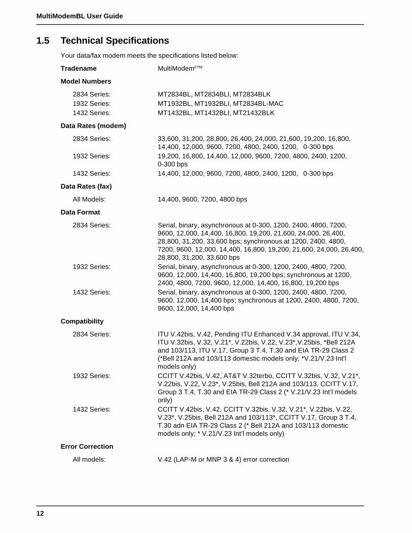
1.5 Technical Specifications
Your data/fax modem meets the specifications listed below:
Tradename MultiModemIITM
Model Numbers
2834 Series: MT2834BL, MT2834BLI, MT2834BLK1932 Series: MT1932BL, MT1932BLI, MT2834BL-MAC1432 Series: MT1432BL, MT1432BLI, MT21432BLK
Data Rates (modem)
2834 Series: 33,600, 31,200, 28,800, 26,400, 24,000, 21,600, 19,200, 16,800,14,400, 12,000, 9600, 7200, 4800, 2400, 1200, 0-300 bps
1932 Series: 19,200, 16,800, 14,400, 12,000, 9600, 7200, 4800, 2400, 1200,0-300 bps
1432 Series: 14,400, 12,000, 9600, 7200, 4800, 2400, 1200, 0-300 bps
Data Rates (fax)
All Models: 14,400, 9600, 7200, 4800 bps
Data Format
2834 Series: Serial, binary, asynchronous at 0-300, 1200, 2400, 4800, 7200,9600, 12,000, 14,400, 16,800, 19,200, 21,600, 24,000, 26,400,28,800, 31,200, 33,600 bps; synchronous at 1200, 2400, 4800,7200, 9600, 12,000, 14,400, 16,800, 19,200, 21,600, 24,000, 26,400,28,800, 31,200, 33,600 bps
1932 Series: Serial, binary, asynchronous at 0-300, 1200, 2400, 4800, 7200,9600, 12,000, 14,400, 16,800, 19,200 bps; synchronous at 1200,2400, 4800, 7200, 9600, 12,000, 14,400, 16,800, 19,200 bps
1432 Series: Serial, binary, asynchronous at 0-300, 1200, 2400, 4800, 7200,9600, 12,000, 14,400 bps; synchronous at 1200, 2400, 4800, 7200,9600, 12,000, 14,400 bps
Compatibility
2834 Series: ITU V.42bis, V.42, Pending ITU Enhanced V.34 approval, ITU V.34,ITU V.32bis, V.32, V.21*, V.22bis, V.22, V.23*,V.25bis, *Bell 212Aand 103/113, ITU V.17, Group 3 T.4, T.30 and EIA TR-29 Class 2(*Bell 212A and 103/113 domestic models only; *V.21/V.23 Int'lmodels only)
1932 Series: CCITT V.42bis, V.42, AT&T V.32terbo, CCITT V.32bis, V.32, V.21*,V.22bis, V.22, V.23*, V.25bis, Bell 212A and 103/113, CCITT V.17,Group 3 T.4, T.30 and EIA TR-29 Class 2 (* V.21/V.23 Int’l modelsonly)
1432 Series: CCITT V.42bis, V.42, CCITT V.32bis, V.32, V.21*, V.22bis, V.22,V.23*, V.25bis, Bell 212A and 103/113*, CCITT V.17, Group 3 T.4,T.30 adn EIA TR-29 Class 2 (* Bell 212A and 103/113 domesticmodels only; * V.21/V.23 Int’l models only)
Error Correction
All models: V.42 (LAP-M or MNP 3 & 4) error correction

13
Chapter 1 - Introduction and Description
Data Compression
All models: V.42bis, (4:1 throughput) or MNP 5 (2:1 throughput) datacompression
Speed Conversion
2834 and 1932 Series: Serial port data rates adjustable to 300, 1200, 2400, 4800, 9600,19,200, 38,400, 57,600 and 115,200 bps
1432 Series: Serial port data rates adjustable to 300, 1200, 2400, 4800, 9600,19,200, 38,400, and 57,600 bps
Flow Control Options
All models: Xon/Xoff, Hardware RTS/CTS, ENQ/ACK, Unix-to-Unix CopyProtocol (UUCP) "Spoofing"
Mode of Operation
All models: Full duplex over both dial-up lines and 2- or 4-wire leased lines;automatic Dial backup on separate lines in leased line operation;automatic or manual dialing, automatic or manual answer
Intelligent Features
All models: Fully “AT command” compatible, microprocessor controlled remoteconfiguration, EIA extended Automode, adaptive line probing,automatic symbol rate and carrier frequency during start-up, retrainand rate renegotiation, autodial, redial, repeat dial, dial linking, pulseor tone dial, dial tone detection, dial pauses, call status display, auto-parity and data rate selection, keyboard-controlled modem options,nonvolatile memory and on-screen displays for modem optionparameters and up to ten telephone numbers/command lines of upto 60 digits each, help menus
Command Buffer
All models: 60 characters
Modulation
2834 Series: Trellis Coded Modulation (TCM) at 33,600, 31,200, 28,800, 26,400,24,000, 21,600, 19,200, 16,800, 14,400, 12,000 and 9600 bps,Quadrature Amplitude Modulation (QAM) at 9600 (non-trellis), 4800and 2400 bps, PSK at 1200 bps, FSK at 300 bps
1932 Series: Trellis Coded Modulation (TCM) at 19,200, 16,800, 14,400, 12,000and 9600 bps, Quadrature Amplitude Modulation (QAM) at 9600(non-trellis), 4800 and 2400 bps, PSK at 1200 bps, FSK at 300 bps
1432 Series: Trellis Coded Modulation (TCM) at 14,400, 12,000 and 9600 bps,Quadrature Amplitude Modulation (QAM) at 9600 (non-trellis), 4800and 2400 bps, PSK at 1200 bps, FSK at 300 bps
Fax Modulations
All models: V.21CH2 FSK at 300 bps, V.27ter DPSK at 4800 and 2400 bps,V.29 QAM at 9600 and 7200 bps, V.17 TCM at 14400, 12000, 9600,and 7200 bps
14
MultiModemBL User Guide
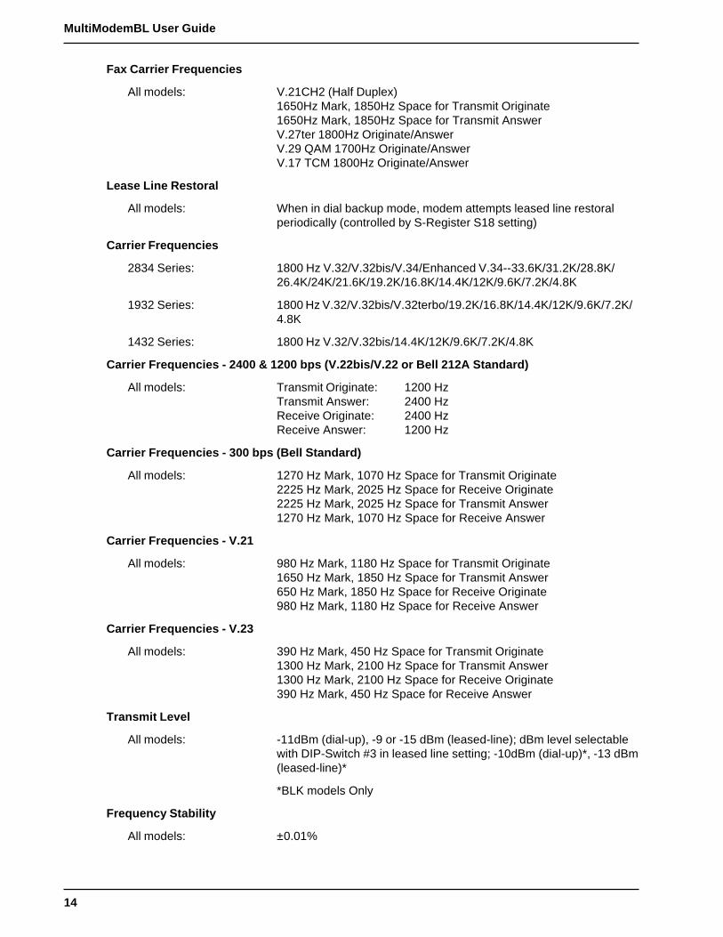
Fax Carrier Frequencies
All models: V.21CH2 (Half Duplex)1650Hz Mark, 1850Hz Space for Transmit Originate1650Hz Mark, 1850Hz Space for Transmit AnswerV.27ter 1800Hz Originate/AnswerV.29 QAM 1700Hz Originate/AnswerV.17 TCM 1800Hz Originate/Answer
Lease Line Restoral
All models: When in dial backup mode, modem attempts leased line restoralperiodically (controlled by S-Register S18 setting)
Carrier Frequencies
2834 Series: 1800 Hz V.32/V.32bis/V.34/Enhanced V.34--33.6K/31.2K/28.8K/26.4K/24K/21.6K/19.2K/16.8K/14.4K/12K/9.6K/7.2K/4.8K
1932 Series: 1800 Hz V.32/V.32bis/V.32terbo/19.2K/16.8K/14.4K/12K/9.6K/7.2K/4.8K
1432 Series: 1800 Hz V.32/V.32bis/14.4K/12K/9.6K/7.2K/4.8K
Carrier Frequencies - 2400 & 1200 bps (V.22bis/V.22 or Bell 212A Standard)
All models: Transmit Originate: 1200 HzTransmit Answer: 2400 HzReceive Originate: 2400 HzReceive Answer: 1200 Hz
Carrier Frequencies - 300 bps (Bell Standard)
All models: 1270 Hz Mark, 1070 Hz Space for Transmit Originate2225 Hz Mark, 2025 Hz Space for Receive Originate2225 Hz Mark, 2025 Hz Space for Transmit Answer1270 Hz Mark, 1070 Hz Space for Receive Answer
Carrier Frequencies - V.21
All models: 980 Hz Mark, 1180 Hz Space for Transmit Originate1650 Hz Mark, 1850 Hz Space for Transmit Answer650 Hz Mark, 1850 Hz Space for Receive Originate980 Hz Mark, 1180 Hz Space for Receive Answer
Carrier Frequencies - V.23
All models: 390 Hz Mark, 450 Hz Space for Transmit Originate1300 Hz Mark, 2100 Hz Space for Transmit Answer1300 Hz Mark, 2100 Hz Space for Receive Originate390 Hz Mark, 450 Hz Space for Receive Answer
Transmit Level
All models: -11dBm (dial-up), -9 or -15 dBm (leased-line); dBm level selectablewith DIP-Switch #3 in leased line setting; -10dBm (dial-up)*, -13 dBm(leased-line)*
*BLK models Only
Frequency Stability
All models: ±0.01%
15
Chapter 1 - Introduction and Description
Receiver Sensitivity
All models: -43 dBm under worst case conditions
AGC Dynamic Range
All models: 43 dB
Interface
All models: EIA RS-232C/ITU V.24
Connectors
BL models: One DB-25 RS-232C connector; three RJ11 for phone line, dial-upand leased line; power.
BLK models: One DB-25 RS-232C connector; two BT plugs for dial-up and leasedline; power
Diagnostics
All models: Power-on Self Test, Local Analog Loop, Local Digital Loop, RemoteDigital Loop, Back-to-Back Test.
Indicators
All models: LEDs for Transmit Data, Receive Data, Carrier Detect, SpeedIndicators, Off Hook, Terminal Ready, Error Correction, Fax, andError
Controls
All models: Toggle switches for Voice/Data with Originate or Answer, Power On/Off; and DIP Switches for various modem options.
Speaker
All models: Speaker for call progress monitoring
Operating Temperature
All models: 0° to 50° C (32° to 120° F)
Power Requirements
All models: 115 Volts AC, 60Hz, 0.3amp (2-prong outlet-mounted transformer)240V/50Hz optional (International).
Dimensions
All models: 6.150" x 9.00" x 1.375"15.6 cm x 22.9 cm x 3.5 cm
Weight
All models: 1.6 pounds/0.72 Kg (without transformer)2.6 pounds/1.18Kg (with transformer)
Limited Warranty
All models: Five Years
16
MultiModemBL User Guide
1.6 Power
Power is supplied through an AC power transformer terminated with a standard two-prong plug. Thetransformer supplies low voltage AC to the modem, and plugs into any conventional 115 volt AC, 60Hz, two-prong power outlet (240 volts AC, 50Hz, .3 Amp for International modems). The powertransformer supplied with the modem is the only one that should be used. Use of any othertransformer could cause damage to the modem. A Power On/Off switch is located on the back of themodem.
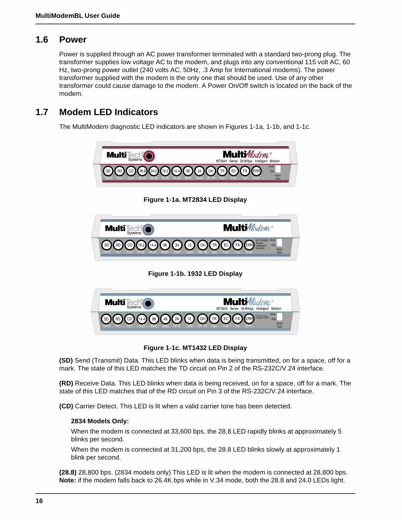
1.7 Modem LED Indicators
The MultiModem diagnostic LED indicators are shown in Figures 1-1a, 1-1b, and 1-1c.
Figure 1-1a. MT2834 LED Display
Figure 1-1b. 1932 LED Display
Figure 1-1c. MT1432 LED Display
(SD) Send (Transmit) Data. This LED blinks when data is being transmitted, on for a space, off for amark. The state of this LED matches the TD circuit on Pin 2 of the RS-232C/V.24 interface.
(RD) Receive Data. This LED blinks when data is being received, on for a space, off for a mark. Thestate of this LED matches that of the RD circuit on Pin 3 of the RS-232C/V.24 interface.
(CD) Carrier Detect. This LED is lit when a valid carrier tone has been detected.
2834 Models Only:
When the modem is connected at 33,600 bps, the 28.8 LED rapidly blinks at approximately 5blinks per second.
When the modem is connected at 31,200 bps, the 28.8 LED blinks slowly at approximately 1blink per second.
(28.8) 28,800 bps. (2834 models only) This LED is lit when the modem is connected at 28,800 bps.Note: if the modem falls back to 26.4K bps while in V.34 mode, both the 28.8 and 24.0 LEDs light.

17
Chapter 1 - Introduction and Description
(24.0) 24,000 bps. (2834 models only). This LED is lit when the modem is connected at 24,000 bps.Note: if the modem falls back to 21.6K bps while in V.34 mode, both the 24.0 and 19.2 LEDs light.
(19.2) 19,200 bps. (2834 and 1932 models only) This LED is lit when the modem is connected at19,200 bps.
(14.4) 14,400 bps. This LED is lit when the modem is connected at 14,400 bps. Note: if the modemfalls back to 12,000 bps while in V.32bis mode, both the 14.4 and 96 LEDs light.
(96) 9600 bps. This LED is lit when the modem is connected at 9600 bps.
(24) 2400 bps. This LED is lit when the modem is connected at 2400 bps.
(12) 1200 bps. (1432 models only) This LED is lit when the modem is connected at 1200 bps.
(OH) Off Hook. This LED is lit when the phone line is "off hook". This occurs when the modem isdialing, on-line, or answering a call. This LED also flashes when the modem is pulse dialing inCommand mode.
(TR) Terminal Ready. When the TR LED is lit, the modem is permitted to answer an incoming call.When it goes off, a connected modem will disconnect. The state of the TR LED matches that of theDTR circuit on Pin 20 of the RS-232C/V.24 interface.
(EC) Error Correction. This LED is lit when the modem is set for V.42 error correction, and flashes onand off when data compression is activated.
(FX) FAX. This LED is lit when the modem is connected in FAX mode.
(ERR) ERROR. When this LED is lit, either the leased line is down and the modem is in dial backupmode, or else the self-test has failed.
1.8 Controls on PC Board
The MultiModem is designed on a single printed circuit (PC) board. This board contains one 16-position DIP-Switch (numbered 1-16). The DIP-Switches are accessible through a cut-out on the sideof the modem. There is also a knob which is used to adjust the speaker volume. This knob isaccessible through the modem's rear panel. The sixteen DIP-Switches control various modemoptions or set default values for Command Mode operation. There is a difference in how several ofthe switches operate depending on whether you are in synchronous or asynchronous mode. Refer tothe switch label on the bottom of the modem for an exact list of the switch functions in asynchronousand synchronous operation. Chapter 9 of this manual also provides detailed instructions onconfiguring all of the modem's PC board options.

18
MultiModemBL User Guide

Chapter 2 - Installation and Connection
20
MultiModemBL User Guide
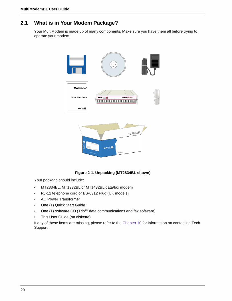
2.1 What is in Your Modem Package?
Your MultiModem is made up of many components. Make sure you have them all before trying tooperate your modem.
MADE IN U.S.AMADE IN U.S.A
Figure 2-1. Unpacking (MT2834BL shown)
Your package should include:
• MT2834BL, MT1932BL or MT1432BL data/fax modem
• RJ-11 telephone cord or BS-6312 Plug (UK models)
• AC Power Transformer
• One (1) Quick Start Guide
• One (1) software CD (TrioTM data communications and fax software)
• This User Guide (on diskette)
If any of these items are missing, please refer to the Chapter 10 for information on contacting TechSupport.
21
Chapter 2 - Installation and Connection
2.2 Installation
The installation of the modem consists of making the physical connections necessary to render themodem functional with your computer. This includes making the proper serial, phone line, and powerconnections. Unless otherwise noted, these instructions apply to all models of the BL series.
2.2.1 Safety Warnings
1 Never install telephone wiring during a lightning storm.
2 Never install telephone jacks in wet locations unless the jack is specifically designed for wetlocations.
3 Never touch uninsulated telephone wires or terminals unless the telephone line has beendisconnected at the network interface.
4 Use caution when installing or modifying telephone lines.
5 Avoid using a telephone (other than a cordless type) during an electrical storm. There may be aremote risk of electrical shock from lightning.
6 Do not use the telephone to report a gas leak in the vicinity of the leak.
7 Ports which are connecting to other apparatus are defined as SELV. To ensure conformity withEN 41003, ensure that these ports are only connected to the same type on other apparatus.
2.2.2 Installation Procedure
The following procedures will guide you through the physical connections required to make yourmodem operational. Software loading is covered later in this guide.
Note: There are two procedures in this section. The first details cabling for domestic (BL) andinternational (BLI) models. The second details cabling for BABT (BLK) models only. Please follow theprocedure that matches your model.
2.2.3 Cabling Procedure (MT1432BL/BLI, MT1932BL/BLI, andMT2834BL/BLI)
Step Procedure
1 Verify that the settings for DIP-Switch #5 and DIP-Switch #10 match those of your systemconfiguration.
The 16-position DIP-Switch (numbered 1-16) is accessible through a cut-out on the right side (asthe LEDs are facing you) of the modem chassis. For a full description of all DIP-Switch Settings,refer to Chapter 9.
DIP-Switch Condition Effect
#5 UP* Selects Answer mode
DOWN Selects Originate mode
#10 UP* Selects Dial-Up operation
DOWN Selects Lease Line operation
* indicates Factory Default setting
2 Verify that the ON/OFF switch at the rear of the modem to the OFF (Down) position.
3 Connect the modem to either a dial-up line or lease-line.
To connect the modem to a dial-up phone line, attach the RJ-11 telephone cord (provided withyour unit) to the PSTN connector on the modem and to a dial-up wall jack. Refer to Figure 2-2.
To connect the modem to a leased line, attach the RJ-11 telephone cord (provided with your unit)to the LEASE connector on the modem and to a leased line wall-jack. Refer to Figure 2-2.

22
MultiModemBL User Guide
PHONE PSTNON
OFFPOWER
EIA RS232C
VOLUME
LEASE
Figure 2-2. MultiModemBL/BLI Connections
4 Attach the EIA RS-232C connector on the modem to the serial port on your computer or terminalwith an RS-232 (or V.24) cable (you supply). Refer to Figure 2-2.
5 To connect a telephone set to the modem (optional) plug one end of an RJ-11 phone cord intothe PHONE connector on the modem, and plug the other end into your telephone. Refer toFigure 2-2.
6 Attach the AC Power transformer provided with your unit to the POWER connector on themodem and to a live AC outlet. Refer to Figure 2-2.
Note: Only apply power to the modem using the power transformer provided with your unit. Useof a power supply not designed for your unit could result in damage to your modem and will voidthe warranty.
7 Apply power to the unit by setting the ON/OFF switch at the rear of the modem to the ON (Up)position. Refer to Figure 2-2.

23
Chapter 2 - Installation and Connection
2.2.4 Cabling Procedure (MT1432BLK and MT2834BLK)
Step Procedure
1 Verify that the settings for DIP-Switch #5 and DIP-Switch #10 match those of your systemconfiguration.
The 16-position DIP-Switch (numbered 1-16) is accessible through a cut-out on the right side (asthe LEDs are facing you) of the modem chassis. For a full description of all DIP-Switch Settings,refer to Chapter 9.
DIP-Switch Condition Effect
#5 UP* Selects Answer mode
DOWN Selects Originate mode
#10 UP* Selects Dial-Up operation
DOWN Selects Lease Line operation
* indicates Factory Default setting
Note 1: BLK models use pins 1 and 6 of the BS-6312 plug for two-wire lines. For four-wire lines,the modems use pins 1 and 6 to transmit and pins 2 and 5 to receive.
Note 2: BABT regulations require that telecommunication cables must be connected to themodem prior to being connected to the network.
2 Verify that the ON/OFF switch at the rear of the modem to the OFF (Down) position.
3 Connect the modem to either a dial-up line or lease-line.
To connect the modem to a dial-up phone line, attach the BS-6312 telephone cord (provided withyour unit) to the PSTN connector on the modem and to a dial-up wall jack. Refer to Figure 2-3.
To connect the modem to a leased line, attach the BS-6312 telephone cord (provided with yourunit) to the LEASE connector on the modem and to a leased line wall-jack. Refer to Figure 2-3.
PSTNON
OFFPOWER
EIA RS232C
VOLUME
LEASE
Figure 2-3. MultiModemBLK Connections
4 Attach the EIA RS-232C connector on the modem to the serial port on your computer or terminalwith an RS-232 (or V.24) cable (you supply). Refer to Figure 2-3.
5 Attach the AC Power transformer provided with your unit to the POWER connector on themodem and to a live AC outlet. Refer to Figure 2-3.
Note: Only apply power to the modem using the power transformer provided with your unit. Useof a power supply not designed for your unit could result in damage to your modem and will voidthe warranty.

24
MultiModemBL User Guide
2.3 Loading Trio DataFAX Software
The following procedure will guide you through the installation of Trio DataFAX software. Theprocedure does not provide every screen or option in the process. The installation utility provides on-screen instructions for those elements that are not covered in this procedure. If you encounterproblems during installation, refer to the Release Notes included on the Trio CD.
1 Turn on your computer and insert the Trio CD into your CD-ROM drive. If you have autorunenabled, the Trio welcome screen will appear. If autorun is disabled, you can start the installationprogram by clicking double-clicking Setup16 or Setup32 from the root directory of the Trio CD.
2 Click the Next ( ) icon to proceed with the default language, English, or select the desiredlanguage and click Next to proceed.
3 Click Next to proceed with the default country, United States, or select the country in which youare installing and click Next to proceed. The Trio Welcome screen is displayed
Note: If you have a sound card installed on your computer and wish to turn off the music portion
of the Trio CD, you can click the Speaker ( ) icon to turn the sound off. Click Speaker again toturn it back on.
4 Click Next. The following dialog is displayed:
5 Click Trio... to continue. The following dialog box is displayed
6 Click Install Trio... to continue. The Select Language dialog is displayed.
7 Click OK to proceed with the default language, English, or select the desired language from thedrop-down list and click OK. The License Agreement dialog is displayed.
8 Read the license agreement, and click OK when you are finished. You are prompted to readimportant information.

25
Chapter 2 - Installation and Connection
9 Click Yes to read the Release Notes. when you are finished, close the release notes dialog andthe Trio Setup dialog is displayed.
10 Click Complete Installation and the installation introduction is presented.
11 Click Next Dialog and follow the on-screen instructions to load the software.
Once the software has finished loading, the following dialog is displayed:
12 Choose Manual Selection of Modem and Ports, then click Next Dialog. The following dialog isdisplayed:
13 In the Com Port Selection group select the COM port, on which your modem is installed, fromthe drop-down list.
14 In the Modem Type group select Class 2 Compatible from the drop-down list.

26
MultiModemBL User Guide
15 Click Next Dialog. The Phone Numbers and Prefixes dialog is displayed.
16 Follow the on-screen instructions and when you are finished, click Next Dialog. The followingdialog is displayed:
17 Click OK, Exit the Installation Program. The Trio Applications program group is displayed.
Your Trio software is loaded. If you wish to begin using Trio right away, double click on the TrioDataFax Voice icon. Refer to the Release Notes for instructions.
To quit Trio altogether, close the Trio Applications program group, and then click the Exit ( ) iconon the installation screen to exit the installation program.
2.4 Is Your Modem Ready for Use?As soon as you have connected power to the modem, if you are an experienced modem user, youmay simply want to check your modem’s settings for data compression, error correction, and so on.You may find that you can get moving quite quickly if you just issue an ATL5, ATL6 and an ATL7command. These commands list how your modem is currently configured. If you come across asetting you’re unsure of, refer to Chapter 5 and Chapter 6 for AT command and S-Registerexplanations and defaults.
If you’re a novice, refer to Chapter 3 to learn about the basics of data communications.
Chapter 3 - Software Configuration and Modem Basics

28
MultiModemBL User Guide
3.1 Introduction
Chapter 2 guided you through the installation of Trio communications software. If you are using adifferent software package, there are some points you should take into consideration. Since yourcommunications software configuration is affected by the capabilities of your computer, this chapterbegins with a discussion of the limitations of some serial ports and how to identify them. It thendiscusses communications configuration in general and recommends settings specifically for theMultiModem. The last section of this chapter walks you through the basics of using your modem.
3.2 Serial Port Limitations
When you configure your software, you need to consider how the hardware on both ends of theconnection will affect the connection. Some serial ports, particularly those in older PC-compatiblecomputers, may limit the performance of the modem. You should know if yours is one of them.
The limiting factor is an integrated circuit called a Universal Asynchronous Receiver/Transmitter, orUART. All data from your modem flows through it. The UARTs typically used in PC-compatiblecomputers are types 8250, 8250A, 16450, and 16550AFN. The 8250 is unreliable above 9,600 bps,and the 8250A and 16450 are unreliable above 19,200 bps. If the modem sends data to the UARTsabove those speeds, the UARTs may not be able to process the data fast enough to keep from losingsome of it. The 16550AFN, however, can safely handle data to 115,200 bps.
When a modem communicates with V.42bis 4-to-1 compression enabled, it sends up to four times asmuch uncompressed data to the serial port as it receives compressed over the telephone line.Therefore, a modem communicating at 14,400 bps may require a serial port that can reliably transferdata at four times 14,400 bps, or 57,600 bps; at 19,200 bps it may require one that works reliably upto four times 19,200 bps, or 76,800 bps; and at 28,800 and 33,600 bps it may require one that worksreliably up to a maximum of 115,200 bps. If your serial port cannot handle these speeds, werecommend that you replace your present serial card with one that has a 16550AFN UART orequivalent.
Macintosh computers do not use UARTs. The Macintosh SE through IIfx models use a Zilog Z8530chip called a Serial Communications Controller, or SCC, that has a maximum speed of 57,600 bps.This speed can be compromised by other serial communications, including printer transmissions andAppletalk, the networking software that allows Macintoshes to share files. When Appletalk is active itcontrols all serial communications on the Macintosh. Because it gives priority to networkcommunications, it may lose modem data at higher transmission speeds. Therefore, when Appletalkis active you risk losing data on serial port communications over 2400 bps, though most users canwork up to 9600 bps without problems. Other activities that could cause the serial driver to drop bitsat high speeds include the floppy disk driver formatting a disk, the CPU paging in or out in virtualmemory mode, and the Mac IIci or IIsi running the on-board video in 8-bit mode. Therefore, formaximum communications speed on the Macintosh, we recommend as few concurrent activities aspossible. To use V.42bis compression at 19,200 bps or faster, we recommend that you install a highspeed serial port card. Newer Macintosh computers, such as the Quadra and Centris models,support serial port speeds up to 115,200 bps.
3.2.1 How Can You Identify Your UART Type?
If you have MS-DOS 6.0 or later, you can find your UART type from a diagnostic program calledMSD. To use it, type MSD at the DOS prompt. After the opening screen, select COM Ports.... Thelast line of the report tells you what type UART you have for each COM port. MSD does notdistinguish between the 8250 and the 8250A. However, if you have an IBM AT or newer computer,you likely have an 8250A or 16450 UART installed, both of which are reliable to 19,200 bps. If youwould like more detailed information about your UART than MSD can provide, you can downloadshareware UART identification programs from the IBM Communications Forum on CompuServe, orfrom a local BBS.
29
Chapter 3 - Software Configuration
3.2.2 The 16550 UART and Windows 3.1
Windows 3.1 may cause a loss of data when communicating at high speed, even with a 16550 UARTinstalled. Because Windows is multitasking—it switches between several programs running at thesame time—it can make the serial port wait briefly while Windows performs other tasks. Meanwhile,incoming data can be lost. The older 8250A and 16450 UARTs can store data in a one-byte first in-first out (FIFO) buffer (a memory area in the UART in which the first bit in is the first out), but oncethe buffer is full, the data is lost. The 16550 has a 16-byte FIFO buffer, which accounts for much of itshigh speed. However, in Windows 3.1, the 16550’s FIFO buffer is disabled by default. To enable thebuffer, use Notepad to open the SYSTEM.INI file in your Windows directory, and add the followingline to the [386Enh] section:
COMnFIFO=1
where n is the number of the COM port the 16550 is installed on. For example, if the 16550 isinstalled on COM2, the line should be:
COM2FIFO=1
After you save SYSTEM.INI you must restart Windows for the change to take effect.
However, there is another problem when the FIFO buffer is enabled: Windows cannot recognize theCOM port because of a bug in the Windows 3.1 serial port driver, COMM.DRV. The only way aroundthis problem is to replace the COMM.DRV file in the WINDOWS\SYSTEM directory with anotherdriver. Several drivers are available commercially or on BBSs that will solve this problem. A freewaredriver called CyberCom is available as CYBERC.ZIP on CompuServe in the IBM CommunicationsForum, Library 0. CyberCom will enable Windows communications at speeds up to 115,200 bps ifyou have a 16550 UART installed.
3.3 Configuring Your Software
Communications software must be configured to work with your modem, your computer, and theremote system it is calling. Fortunately, most communications programs make the process easy byproviding a default initialization string for your modem as well as defaults for most of the otherrequired parameters.
3.3.1 Configuring Software for Your Modem
Because remote computers may have different connection requirements such as speed, number ofbits, parity, log-on sequences, etc., communications software is typically configured by sessions,each session having a unique configuration for a given connection (e.g., to a BBS or commercial on-line service). Most communications programs, however, have a separate modem configuration menubecause modem configurations rarely change from session to session.
The most important configuration is the modem initialization string. This is a sequence of commandsthe software uses to configure the modem when the communications software is loaded or when asession begins. Always begin the initialization string with the ATtention command AT, then follow itwith the modem reset command, &F. Issuing a reset command before other commands ensures thatyou are starting with a known state.
The rest of the commands in the initialization string depend on the capabilities of the modem andwhat you want it to do. Some older communications programs require you to create the initializationstring by yourself. Most modern communications programs, however, provide you with a ready-madeinitialization string that is automatically selected when you choose your modem model from a list. It isa poor idea to use an initialization string intended for another modem, especially one from anothermanufacturer, because modem capabilities and command implementations vary from modem tomodem. However, if your MultiModem does not appear on a modem list, you may use theMultiModemII initialization string.
30
MultiModemBL User Guide
3.4 PC Initialization Strings
We recommend the following initialization string for a MultiModem connected to a PC-compatiblecomputer when sharing a line with a telephone:
AT &F X4 S0=0 ^M
This string resets the modem to the factory default settings, selects extended result codes with NODIAL TONE and BUSY, and turns off auto-answer. ^M must end every string sent to the modem fromsoftware. It is the ASCII code for the RETURN key on most keyboards, and the default code for thecarriage return character in the modem and most communications programs. The carriage returncharacter is defined in the modem in S-register S3; if you change it, you must also change thecarriage return character code used in your communications software. If you send a commanddirectly to the modem in terminal mode rather than indirectly through communications software, youmust end the command string by pressing the RETURN key (<CR>) instead of adding ^M to thestring.
The following initialization string is for a MultiModem on a telephone line that functions solely as aDATA LINE:
AT &F X4 S0= 2 ^M
3.4.1 Changing Default Parameters
By default, the modem will answer after the first ring and try to communicate with a modem on theother end of the line. If you have one telephone line for voice, fax, and modem communications, themodem may attempt to answer all incoming calls, voice as well as data. To change auto-answer todefault off, open your communications program and type the following string in the terminal window:
AT &F S0=0 &F9 &W0 <CR>
This string selects the factory default parameters, then turns auto-answer off and stores that setting,along with all other current parameters, in nonvolatile memory. The &F9 command causes themodem to load the values from nonvolatile memory the next time it receives the &F command. Youwill use the same initialization string as before:
AT &F X4 ^M
But now the modem will load the values stored in nonvolatile memory when you turn on the modemand when you issue the ATZ or AT&F reset commands.
Note: Because it clears the command buffer, you should not use ATZ in an initialization string.
3.4.2 Other Parameters
The default values for the other parameters in modem configuration menus rarely need changing.They typically include the dialing prefix (ATDT for touch-tone service and ATDP for rotary service),the dialing suffix (^M), the hang-up string (+++ATH0^M), and response messages (RING, NOCARRIER, BUSY, etc.). Communications software with a host mode might also include an auto-answer string (AT S0=1^M).

31
Chapter 3 - Software Configuration
3.5 Macintosh Initialization
Macintosh computers cannot use RTS/CTS hardware flow control without a serial cable wired forhardware control. The Macintosh 128 and 512 models cannot use RTS/CTS flow control at all. Forthose Macintoshes turn off the default RTS/CTS hardware flow control, turn on XON/XOFF flowcontrol and pacing, and ignore DTR:
AT &F X4 &E5 &E13 &D0 ^M
For hardware flow control, use the following initialization string:
AT &F X4 &E13 &D0 ^M
Add S0=0 to both strings to disable auto-answer if the modem is on a voice line.
You can store the initialization string in nonvolatile memory. With your communications software openand connected to the modem’s COM port, type the initialization string in the terminal window,substituting a carriage return for ^M. To store the string, enter
AT &F9 &W0 <CR>
Now you can initialize your modem with the following simple string:
AT Z ^M
3.6 Configuring Software for Your Computer
You must configure your communications software to match your computer’s configuration. If themodem is connected to the COM2 serial port, you must tell the software you are using COM2.Another important parameter is the serial port baud rate. This is the speed at which your modemcommunicates with your computer, not the speed at which your modem communicates with anothermodem. When V.42bis data compression is enabled, you must have a serial port baud rate fourtimes the transmission speed of the modem to fully optimize compression. So if your UART is fastenough, you should set the serial port baud rate to a minimum of four times the top speed of yourmodem.
If you have an 8250 UART, your most reliable serial port speed will be 9600 bps; if you have an8250A or a 16450 UART, try 19,200 bps; if you have a 16550 UART or equivalent, a serial portsetting of 115,200 bps can be set reliably.
3.6.1 Configuring Software for the Remote System
You must meet the requirements of the remote system for successful communications. Though themodem can automatically match the speed of the other modem, you must specify parameters suchas type of flow control, break length, number of data bits, number of stop bits, and parity. If you setthese parameters incorrectly with the remote system, gibberish will appear on your screen.
3.6.2 Terminal Emulation
If you are accessing the remote computer as if from an on-site terminal, the keyboard codes used byyour computer may not match the ones used by the remote computer. To be compatible with theremote computer, your software must be able to substitute the appropriate codes in what is known asterminal emulation. Most communications programs can emulate the most common mainframeterminals, including the DEC VT100, VT102, and VT52 terminals, and the basic TTY mode. If indoubt about which to choose for a BBS, try ANSI or VT100 first.

32
MultiModemBL User Guide
3.6.3 File Transfer Protocols
When you upload or download files with your modem, the host computer will ask which file transferprotocol you want to use. Most communications programs allow you to choose a default protocol.Your software’s documentation should list the ones it can use (not all communications programssupport all protocols). Zmodem is the recommended protocol for most transfers.
3.7 When to Disable Data Compression
If your serial port cannot keep up because it has an older UART, you may lose data when using datacompression. Also, the speed advantage hardware compression gives you is entirely dependent onhow much the data being transmitted can be compressed. If the data is already in compressedform—a .ZIP or a .SIT file, for example—trying to compress it more will actually slow the transmissionslightly compared to transmitting the same file with compression disabled. This effect will be mostnoticeable if your modem negotiates MNP 5 compression with the other modem. V.42bis will not tryto further compress a compressed file, but MNP 5 will.
The command to disable compression is AT &E14 <CR>. If you have an older UART or if you useyour modem mostly for downloading long, compressed files from BBSs, you may want to include the&E14 command in your initialization string as follows:
AT &F S0=0 X4 &E14 ^M
As a general rule, you should try to transmit files in already-compressed form rather than relying onV.42bis hardware compression. Because software compression is more efficient than hardwarecompression, you will have a higher throughput with the former. Of course, this efficiency does notinclude the time spent compressing and decompressing .ZIP or .SIT files, but it will save on phonebills. And hardware compression will still be there for those occasions when it is inconvenient tocompress a file with software. Note also that when you download files with compression disabled,you can use a slower serial port if you have an older UART.
3.7.1 Disabling Error Correction
By default, the modem is set to auto-reliable mode. In this mode the modem determines during thehandshake whether the other modem is using V.42 error correction. If it is, the modem then switchesitself to reliable mode and enables error correction. If it is not, the modem remains in non-errorcorrection mode.
Normally, we recommend that you leave the modem set to auto-reliable mode (&E1). However, youmay encounter some circumstances in which the modem will work better with error correction turnedoff. For example, it has been reported that on CompuServe error correction will slow file transfers atmodem speeds of 9600 bps and under. If this is a problem for you, you can turn off error correctionwith the command AT &E0, or you can include the command in your initialization string as follows:
AT &F S0=0 X4 &E0 ^M

33
Chapter 3 - Software Configuration
3.8 Modem Basics
You control your modem by issuing AT commands, setting S-Registers, and setting DIP-Switches.You can easily change the settings of your DIP-Switches, as they are located on the right side ofyour modem’s chassis. Right now your modem is set up for the most typical user application, that is,as a traditional modem set to make a dial-up call to a remote installation where the call is answeredautomatically; therefore, you shouldn’t need to change the DIP-Switches. (If however, you know thatyour application does not follow this profile, please refer to Chapter 9 for full details on DIP-Switchsettings.)
While you may operate your modem manually, it is more likely that you will use your datacommunications software to either:
• enter “terminal” mode, where you can “speak most directly” to the modem by issuing ATcommands, or to
• launch a datacomm session through a set of modem configurations which you select and thenassociate with a target telephone number. Once you have created, saved, and named this set ofinformation according to your connection needs and your datacomm software’s conventions, thesoftware then simplifies your dialing because you needn’t re-configure your modem, nor run therisk of mistakenly keying-in incorrect information.
Either way, you need to understand that an AT command is the method by which your modem iscontrolled, and must therefore prefix nearly all commands. AT stands for attention, and alerts themodem that a command follows. You may enter these commands with either upper- or lowercasecharacters. Entering AT automatically sets the modem’s serial baud rate to match your computer’sand also sets the modem’s parity. It also clears the modem’s command buffer.
Once you’re in terminal mode, enter AT followed by <CR> to check whether your modem isoperational. If everything’s fine, your modem will respond OK. (Note: refer to Chapter 4 for additionaldetails on Dialing, Automatic Answering, Dial Back-Up and Automatic Leased Line Restoral.)
3.8.1 Simple Operations
You can dial a number by using the ATD command and the phone number of the modem with whichyou wish to connect, e.g., ATD6127853500. Your modem will dial the number, and hear a“scrambling” noise as the modem negotiates the kind of connection it can make, and once themodems have settled on a common connection, you will receive a connect message on yourcomputer’s video display. As the modem dials and connects, you may notice changes across its frontLED panel: the OH (Off Hook) LED lights to let you know the modem is operating as if you hadpicked up the handset to a phone. The CD (Carrier Detect) LED lights to let you know the modemhas detected a device it can connect to. A speed LED lights to let you know at which speed theconnection has been made.
To hang up a call, enter +++ATH<CR>. Your modem will return on hook, just as if you had returned aphone’s handset to its cradle. Notice also that the OH, CD and speed LED’s are no longer lit. Yourvideo now displays OK, signifying that your modem is ready for your next command.
3.9 The Answer/Originate - Voice/Data Toggle Switch
Located on the front of the modem is a Voice/Data "toggle" switch with Originate/Answer capabilities.This switch enables the modem to automatically dial a phone number stored in the N1 location ofmemory whenever this switch is toggled. (Note that you must first enter AT$VD1&W0<CR>. Thiscommand string enables Voice/Data dialing when the Voice/Data toggle switch is activated.)
If you are "Manually" dialing with an attached telephone device (and not with your keyboard), yourmodem originates when toggled in that position (DOWN); and if you are "Manually" answering(modem is not configured to automatically answer via S-Register S0 setup), the modem answers anincoming call when toggled in that position (UP).

34
MultiModemBL User Guide

Chapter 4 - Manual Dial and Automatic Answer
36
MultiModemBL User Guide
4.1 Introduction
We’ll assume that yours is the very common application, where you are using a modem to dial up aremote computer. The modem has been factory preset for originating a call to a compatible 33,600bps modem (also set up for hardware flow control, V.42 error correction, V.42bis data compressionand CTS/RTS operation). If the answering modem is not set up similarly, the modem automaticallyadjusts to the appropriate protocol.
4.2 Dialing/On-Line/Answering
There are several basic steps for “originating” and “answering” in data communication mode:
1. Load communication software
2. Dial
3. Establish On-Line connection
4. Terminate Call
A simple way to dial is from the keyboard of your computer or terminal. You enter a command on thekeyboard to tell the modem to dial.
If you use a sophisticated communications software package, the software tells you to enter phonenumbers and other information. If this is the case, the software, and not you, gives the dialingcommands to the modem. All of the commands, option registers and intelligent features of themodem is taken care of by the software.
If you are giving commands directly to your modem (and not through your software), each commandmust begin with AT (ATtention Characters). AT characters may be entered in upper or lower case.
Entering AT automatically sets the modem’s speed to match the speed of the computer or terminal,and also sets the modem’s parity.
The AT characters alert the modem that a command follows. The AT Command can also be used toclear the command buffer, by simply typing AT and hitting RETURN.
The letter D in a command causes the modem to dial the numbers immediately following it (e.g.,ATD6127853500). You have a choice of either pulse (ATDP) or tone (ATDT) dialing methods.
The modem responds with “CONNECT” on your video display after the number is dialed and aconnection signal is detected. The modem is now in “On-Line” mode, and is ready to communicatewith a host site.
If no connection signal is detected within 45 seconds (this time period can be adjusted by S-RegisterS7), the modem goes On Hook/hangs up and returns to Command mode. At this point, your videodisplays “NO CARRIER”.
Enter +++ATH to Hang Up On-Line (bring modem on-hook), and terminate the modem's On-Linemode. At this point, your video displays “OK”.
In addition to the call originating capabilities, the modem can also automatically answer incomingcalls. You need not be present. You can, however, control the situation by configuring the modem toeither answer or not to answer, or to answer after a specified number of rings. This is done by settingthe value of S-Register S0 (modem defaults to automatically answer an incoming call after one ring).Refer to Chapter 6 for S-Register details.
37
Chapter 4 - Manual Dial and Automatic Answer
4.3 Automatic Leased Line Restoral Operation
When the modem is in Dial Backup mode, it periodically checks the leased line to see if it'soperational and tries to restore the leased line if possible. S-Register S18 determines how oftenrestoral attempts occur. The default for S18 is 30 minutes, and can be set in one minute incrementsfrom 10 to 255 minutes. Setting the restoral attempts under 10 minutes causes excessive breaks inthe dial-up operation.
Note: both local and remote modems must have S-Register S18 set identically. Refer to Chapter 6for more information on S-Register S18.
4.4 Manual Dial Backup Call Termination
With your modem in leased line mode (DIP-Switch #10 in the DOWN position) and with dial backupoperation in process, there are two ways to manually terminate the dial backup call (other thanautomatic leased line restoral). In each case, you will try to establish the leased line connectionbecause it is back in operating condition. The methods of dial backup call termination are:
1) Manual Control. The "Voice/Data" switch can be used to change from a dial back line to leasedline by toggling down once. When that is done, the modem tries the leased line connection, and,if it is good, the modem disconnects the dial back call and establishes a leased line connection.
2) DTR Control. If DTR (Data Terminal Ready) is turned off for 50 milliseconds or more, adisconnect occurs. This is probably the most common method used by computer systems at theautomatic answer end of the line to cause the answering modem to disconnect after toggling offprocedures.
4.5 Dial Backup and Leased Line Restoral
The dialing associated with the MultiModem, when in leased line with dial-back mode, involvesplacing a call from the originating modem due to a leased line failure.
After a preset period of time (determined by S-Register S18), the modem automatically tries torestore the leased line.
The parameters used to determine if a leased line is down (so automatic dial back can occur), isbased on the modem doing a “retrain” on the leased line due to an error condition in the transmission.An error condition is defined as a "hit" on the line (the Carrier gets interrupted).
The retrain is a "handshake" procedure between the modems to establish the Carrier again. If theretrain fails, both modems (originate and answer modems) start their Dial-back timers. The time isdetermined by S-Register S19 settings. The S19 default setting is one minute. During that minute, theoriginate modem tries to establish the leased line link. If the leased line is established during thattime, the timer is cleared and everything is back to normal. If the timer expires, the modems goes todial-back mode.
The purpose of the timer for the Answer modem is to determine when it accepts a dial-up call. Whenboth timers have expired and the leased line has not been established, the dial-back procedurestarts. The number dialed is the one stored in location N9 of the originate modem's phone numbermemory. In the preparation for proper dial-back operation, enter the proper number in the N9 locationusing the commands detailed in Chapter 5. Keep in mind that the number also can be dialed inV.25bis Command mode.

38
MultiModemBL User Guide
4.6 Dial-Up Operation
When your modem is used as a dial-up modem (DIP-Switch #10 in the UP position), it can bothoriginate and answer calls. To originate calls, you use the automatic dialing capability of the modem'sCommand mode.
To do this, use the computer or terminal keyboard to enter a few command letters, followed by thephone number you wish to dial. If you have a computer with sophisticated communications software,you may end up talking back and forth with the software, and the software will take care of talking tothe modem.
It is still possible, however, to dial your data calls using a telephone set. There are few reasons whyyou would want to do this, but if you have a need to use the telephone set to dial, we explain how inthe next section. We will delay our coverage of Command Mode autodialing, and all other CommandMode features, until Chapter 5.
4.7 Manual Call Origination
You can use the modem to both originate and answer calls. To originate calls in Asynchronous mode,you will most likely use the modem's Command mode, and give the modem automatic dialingcommands (we will delay our discussion of the Command mode until Chapter 5). When using yourmodem in Synchronous mode, the Command mode is disabled, so you must automatically dial yourcalls with a telephone set. To use manual dialing, you first connect an ordinary telephone set (eithertouch tone or rotary dial) to the modem's PHONE Jack, if you have not already done so. Next, set thespeed selection, (DIP-Switches #13 and #14), to the speed at which you wish to communicate.These DIP-Switches are located on the side of the modem. (Refer to Chapter 9 for DIP-Switchsettings.) Your computer or terminal may be set for up to 115,200 bps (57,600 bps for 1432 models).
When your telephone set is connected, you can use it to dial the modem you wish to call. Simply dialthe number, and then listen to the dialed modem's answer tone. When you hear it, press the Voice/Data switch on the front of the modem down (to the Originate position). You don't have to hold itdown. Just "toggle it" (press it once and let it go). Once you press the switch, the tone you hearshould change to another pitch, or change into a rough-sounding scrambled noise. You then replacethe telephone handset in its cradle, and your data communications begins.
Note that the modem may call manually via the keyboard command ATD, or by pressing the Voice/Data switch on the modem's front panel downward. To force the modem to automatically answercalls, either type ATA, or press the Voice/Data switch on the modem's front panel upward.
39
Chapter 4 - Manual Dial and Automatic Answer
4.8 Automatic Answering
The modem can be used as an automatic answering modem. No special modifications or settings arerequired other than making sure that the Auto-Answer select switch is set to Auto-answer enabled(DIP-Switch #5 UP).
The modem, when in its idle state, is set for Originate mode frequencies. An incoming ring signalautomatically switches the modem into Answer mode.
You can program the modem to answer a call after a certain number of rings using S-Register S0(see Chapter 6). Refer to Section 4.10 for the handshaking procedures used by the modem when inautomatic answer mode.
In many originate-only applications, you may wish to disable the automatic answer capability of themodem. If a telephone set is connected to the modem, you may wish to receive incoming calls in avoice mode for normal voice conversation. If auto-answer is not disabled, all incoming calls areanswered by the modem, preventing voice communications. To disable automatic answer, place DIP-Switch #5 to the DOWN (Disable Auto Answer) position (refer to Chapter 9).
Another way to disable automatic answer is to use S-Register S0 to configure the modem to answeron the nth ring, where n equals zero (0). Another alternative is to have the modem answer after fiveor six rings, which gives you time to answer it manually if you wish. (See Chapter 6 for S-Registerinformation.)
4.9 Manual Answering
We have shown that the modem can automatically answer incoming calls. The MultiModem can alsoanswer manually, under your control. The most typical application involves you and another person,who, after carrying on a voice conversation, want to convert to data communications between yourmodems without having to hang up and dial again.
The problem here is that both modems are in originate mode. For two modems to communicate, oneof them must be in originate mode and the other must be in answer mode. The solution here is toforce either one of the two modems to Answer mode, and the other to Originate mode.
The modem can be forced into either Answer mode or Originate mode by using the Voice/Dataswitch on the front of the modem.
In our example, let's say that you and your friend Bill have just had a voice conversation. Both of youhave your telephones connected to your modems, and your modems are connected to computers orterminals. Set the speed switches to the proper speed on both modems. To switch to Data modefrom Voice mode, you would switch the Voice/Data switch Down (to the Originate position), and Billwould switch his up to Answer. This switches your modem to the originate on-line mode, and Bill's tothe Answer on-line mode. You would both then hang up your telephone handsets, and continue theconversation via your keyboards.

40
MultiModemBL User Guide
4.10 Handshaking Details
This section briefly explains what happens between two modems in a normal call. We are assumingthat there are MultiModems at both the originating and at the answering end of the telephone line. (Ifother brands of modems are used with our modems, they will still communicate, but eachmanufacturer tends to use slightly different delay timings and sequences, and many of the brandsvary in their LED designations.)
When a call is dialed from the originating modem, the called modem responds to the ringing byswitching into Answer mode and by turning on its RI (Ring Indicator, RS-232C/V.24 Pin 22) signal asthe rings are detected. (The BL-MAC models do not use DTR.)
Note that in order for the called modem to be able to answer the call, it must have a high DTR (DataTerminal Ready) signal. This signal comes from the computer or terminal to which it is attached, onRS-232C Pin 20.
When the called modem answers the call, its OH (Off Hook) circuit comes on and the ringing stops.Two seconds after the call is answered, the called modem begins transmitting its answerback tone.
The originating modem, which has been off hook and waiting for the answerback tone, turns on itstransmitter when it hears the tone. Then after a one second delay, the orignating modem's CD(Carrier Detect) comes on.
The called modem then responds to the originating modem by turning on its CD (Carrier Detect)signal, and the handshaking is completed.
Note: With the modem in Reliable or Auto-Reliable mode, some additional handshaking takes place.This is explained in Section 5.4.8.
4.11 Call Termination
There are a number of ways to terminate a call, or simply stated, hang up. They are:
1) Command Mode Control. To terminate a call by Command Mode, enter +++ATH thenRETURN; or, send a BREAK signal followed by ATH and a RETURN.
2) DTR Control. If DTR (Data Terminal Ready) is turned off for 50 milliseconds or more, adisconnect occurs. This is probably the most common method used by computer systems at theautomatic answer end of the line to cause the answering modem to disconnect after logging offprocedures.
3) Loss of Carrier. After a data connection is established, the modem disconnects if a loss ofcarrier occurs for 700 milliseconds (0.7 seconds) or more. Note that one cause of carrier losswould be if one of the modems disconnect normally.
4) Abort Timer.
Answer Mode: When OH (Off Hook) comes on, the called modem starts a forty-five-secondtimer and waits for a carrier signal from the originating modem. If carrier is not detected withinthis period, the modem disconnects (hangs up) and is ready for another call.
Originate Mode: The abort timer functions the same as in answer mode, except that the timerbegins after the modem has completed dialing, instead of when it first goes off hook. It is possibleto change this forty-five second wait period to any other value (from 0 seconds up to 255seconds), or to disable the timer completely by re-configuring S-Register S7 (see Chapter 6).
5) Inactivity Timer. Causes the modem to disconnect if no data is transmitted or received for aspecified time. The timer is restored any time a character is passed through the serial port ineither a send or receive state. This timer runs in both normal or reliable connections and iscontrolled by S-Register S30. The Inactivity Timer can be disabled by setting S30 to 0, which isthe factory default setting.

Chapter 5 - Command Mode
42
MultiModemBL User Guide
5.1 Introduction
AT commands are the means by which you, and your communications software, are able tocommunicate with and configure your modem. They enable you to establish, read, and modifyparameters in addition to dialing. The following provides both a summary and a detailed explanationof the AT commands recognized by the MultiModem.
5.1.1 AT Command Editing
The BACKSPACE key on your keyboard can be used to edit characters in the AT command line. AnAT command is not executed until the RETURN key is pressed. The BACKSPACE key erases theprevious character for reentering.
The BACKSPACE key does not erase the AT characters once they are entered. If your keyboardhas no BACKSPACE key, CTRL-H does the same thing. The character recognized by the modemas BACKSPACE may be changed to any other ASCII character with S-Register S5.
If you wish to cancel an entire command that has been entered but not yet executed, enter CTRL-X.This also clears the command buffer. The effect is the same as backspacing to cancel the entirecommand, only quicker.
Characters entered in a command are stored in the modem's Command Buffer (memory) untilexecuted by hitting RETURN. The Command Buffer's capacity is sixty characters. The AttentionCharacters AT do not count in the sixty allowed Command characters. Spaces, which may be usedfor increased display readability, may be used when entering a command, but are not stored in theCommand Buffer and are not counted in the sixty allowed characters. Hyphens, parentheses, etc. arenot allowed.
If the sixty character limit is exceeded or if invalid characters are entered, the Command Bufferautomatically erases, and an ERROR message appears. You would then re-enter your commandwithin the sixty-character maximum, using only the allowed characters.
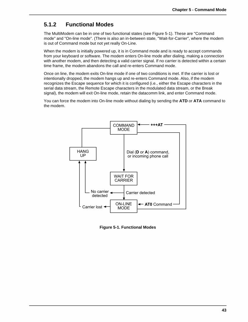
43
Chapter 5 - Command Mode
5.1.2 Functional Modes
The MultiModem can be in one of two functional states (see Figure 5-1). These are "Commandmode" and "On-line mode". (There is also an in-between state, "Wait-for-Carrier", where the modemis out of Command mode but not yet really On-Line.
When the modem is initially powered up, it is in Command mode and is ready to accept commandsfrom your keyboard or software. The modem enters On-line mode after dialing, making a connectionwith another modem, and then detecting a valid carrier signal. If no carrier is detected within a certaintime frame, the modem abandons the call and re-enters Command mode.
Once on line, the modem exits On-line mode if one of two conditions is met. If the carrier is lost orintentionally dropped, the modem hangs up and re-enters Command mode. Also, if the modemrecognizes the Escape sequence for which it is configured (i.e., either the Escape characters in theserial data stream, the Remote Escape characters in the modulated data stream, or the Breaksignal), the modem will exit On-line mode, retain the datacomm link, and enter Command mode.
You can force the modem into On-line mode without dialing by sending the ATD or ATA command tothe modem.
$��� �� �� �# %�&&�'���� �'%�&�'( �)�'� %���
*������ ����%���
+,-./0
1-��2-3�1$3
4,2� 51�*,��23�
*1��,-$�1$3
��� *�&&�'�
�����
-� %����������%���
*������ ����
Figure 5-1. Functional Modes

44
MultiModemBL User Guide
5.2 Summary of AT Commands
A wide variety of autodial operations and modem options can be controlled when the modem is inCommand Mode. Remember, nearly all commands begin with AT.
These commands are organized into several functional groups. An alphabetical summary ofcommands is provided in Appendix D.
HOW TO COMMANDS
DIAL D DialA: or : Continuous Redial (Not Active in BLK models)$D DTR Dialing$VD Voice/Data DialingN Dial a Stored Number
MODIFY DIALING P/T Pulse/Tone DialingPROCEDURES &P Set Pulse Dial Ratios (Not Active in BLK models)
, Automatic Pauses in dialingY Long Space DisconnectW Wait for New Dial Tone; Return to Command Mode After Dial
CommandR Reverse Mode of Operation! Flash On Hook$ AT&T "Calling Card" Tones@ Quiet Answer
MEMORIZE PHONENUMBERS D...N Store Phone Numbers
NN Number LinkingL List Numbers Stored in Memory
STORE MODEM &F Load Factory DefaultsCONFIGURATIONS &W Store Configuration & S-RegisterAND DEFAULTS Parameters
Z Reset ModemV Result Code Terse/Verbose$SP UNIX/"Spoofing”&M Synchronous/Asynchronous Mode Select&X Synchronous Transmit Clock Select
CONFIGURE Q Result Codes Enable/Disable ResponseCOMMAND &Q Result Code SelectionRESPONSES E Echo Command Characters
V Result Code Terse/VerboseX Result Code...Basic/Extended/Call Progress
CONDITION &G Guard Tones (Not Active in BLK models)PHONE LINE M Monitor Phone Line
&T Remote Digital Loop Signal#T Enable/Disable Trellis Coded ModulationB Bell/V.21 Tones (Not Active in BLK models)#F Fallback When On-Line&CD Cleardown at Disconnect (2834 Series only)#A Auto-Speed Detect

45
Chapter 5 - Command Mode
CONTROL RS232C &C Carrier Detect ControlINTERFACE &D Data Terminal Ready Control
&R Clear To Send Control&S Data Set Ready Control&RF CTS/RTS Control&SF DSR/CD Control
CONFIGURE &E0 Normal ModeERROR &E1 Auto-Reliable ModeCORRECTION &E2 Reliable Mode
#L0 Negotiate V.42 Mode During Handshake#L1 MNP On/LAPM Off#L2 LAPM On/MNP Off#L3 Direct LAPM/Phase Out Handshake$A Auto-Reliable Buffering$F Enable/Disable Auto-Reliable Fallback Character$R Retransmit Count$E Error Correction at 300 bps
CONFIGURE &E3 Flow Control DisabledFLOW CONTROL &E4 Hardware Flow Control
&E5 Xon/Xoff Modem-Initiated&E6 Xon/Xoff Modem Responds/No Pass-Through&E7 Xon/Xoff Modem Responds/Pass-Through Allowed#X Send Single/Multiple Xoff Characters&E8 Enq/Ack Off&E9 Enq/Ack On&E10 Normal Mode Modem Flow Control Off&E11 Normal Mode Modem Flow Control On&E12 Computer-Initiated/Off&E13 Computer-Initiated/On&BS Maximum Block Size$EB 10/11 bit Asynchronous Format#P Parity Selection
CONFIGURE DATA &E14 Data Compression DisabledCOMPRESSION &E15 Data Compression Enabled
CONFIGURE SPEED $BA0 Speed Conversion OnCONVERSION $BA1 Speed Conversion Off
$MB Set modem speed (e.g.,$MB14400)$SB Set serial port speed (e.g.,$SB57600)
EXECUTE $H HelpIMMEDIATE I Product Code InquiryACTION I 9 Windows 95 Autodetect Inquiry (2834 Series only)COMMANDS L5 List Current Operating Parameters
L6 List S-Register ValuesL7 List additional Configuration Parameters L8 List On-Line DiagnosticsH Off Hook
+++AT<CR> Escape Sequence: Entering Command Mode while On-Line%E Escape Sequence Options...Entering Command Mode while On-LineA Force Answer ModeO Exit Command Mode/Go Back On-Line
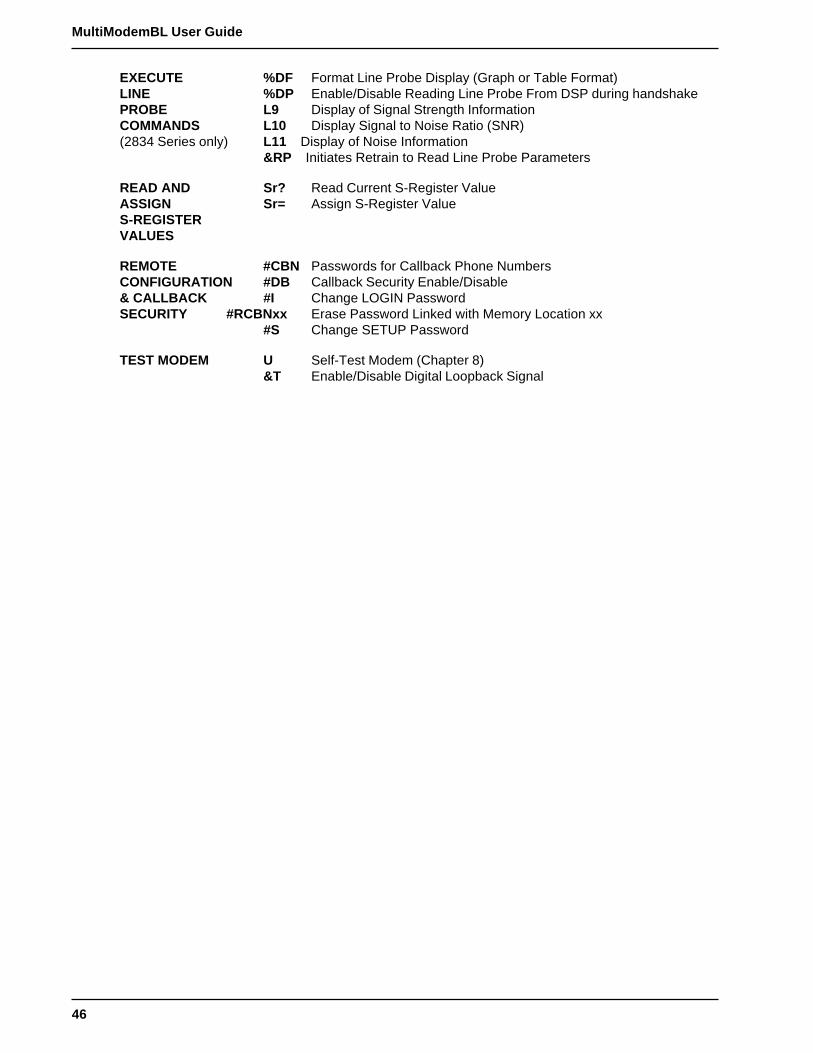
46
MultiModemBL User Guide
EXECUTE %DF Format Line Probe Display (Graph or Table Format)LINE %DP Enable/Disable Reading Line Probe From DSP during handshakePROBE L9 Display of Signal Strength InformationCOMMANDS L10 Display Signal to Noise Ratio (SNR)(2834 Series only) L11 Display of Noise Information
&RP Initiates Retrain to Read Line Probe Parameters
READ AND Sr? Read Current S-Register ValueASSIGN Sr= Assign S-Register ValueS-REGISTERVALUES
REMOTE #CBN Passwords for Callback Phone NumbersCONFIGURATION #DB Callback Security Enable/Disable& CALLBACK #I Change LOGIN PasswordSECURITY #RCBNxx Erase Password Linked with Memory Location xx
#S Change SETUP Password
TEST MODEM U Self-Test Modem (Chapter 8)&T Enable/Disable Digital Loopback Signal

47
Chapter 5 - Command Mode
5.3 Result Codes
The Command mode provides you with several responses, or “Result Codes”, that can aid you inCommand mode operation. These Result Codes are displayed on your video monitor.
You can choose result codes that closely match those of the standard AT command set, or chooseenhanced function result codes that have been used in Multi-Tech modems ("Multi-Tech" responses).The &Q command selects which result codes will be used.
You can choose to have these Result Codes displayed in either “verbose” (full words) or “terse”(digits) format. This is controlled by the ATV0 (terse) or ATV1 (verbose) commands. The modemdefaults to verbose format.
AT&Q0 selects Multi-Tech responses with Reliable/LAPM/Compression modifiers. The terseresponse code for CONNECT 2400 is 9. AT&Q1 selects Standard AT command set responses. Theterse result code for CONNECT 2400 is 10.
The following tables define the result codes generated by the &Q command (refer to Appendix G forResult Code Summary).
"Multi-Tech" Result Codes
2834 Series
TERSE VERBOSE TERSE VERBOSE
0 OK 11* CONNECT 48001 CONNECT 12* CONNECT 96002 RING 13* CONNECT 144003 NO CARRIER 19* CONNECT 192004 ERROR 21* CONNECT 216005* CONNECT 1200 24* CONNECT 240006 NO DIALTONE 26* CONNECT 264007 BUSY 28* CONNECT 288008 NO ANSWER 31* CONNECT 312009* CONNECT 2400 33* CONNECT 33600
1932 Series
TERSE VERBOSE TERSE VERBOSE
0 OK 8 NO ANSWER1 CONNECT 9* CONNECT 24002 RING 11* CONNECT 48003 NO CARRIER 12* CONNECT 96004 ERROR 13* CONNECT 144005* CONNECT 1200 19* CONNECT 192007 BUSY
1432 SeriesTERSE VERBOSE TERSE VERBOSE
0 OK 7 BUSY1 CONNECT 8 NO ANSWER2 RING 9* CONNECT 24003 NO CARRIER 11* CONNECT 48004 ERROR 12* CONNECT 96005* CONNECT 1200 13* CONNECT 14400
* With MNP error correction on, RELIABLE (or R) is added to these result codes. With LAP-M errorcorrection on, LAP-M (or L) is added to these result codes. With data compression on,COMPRESSED (or C) is added. (Note these "Extended" Result Codes are displayed when yourmodem is set up to do so with an X1, X2, X3, or X4 command.)

48
MultiModemBL User Guide
"Standard AT" Result Codes
2834 Series
TERSE VERBOSE TERSE VERBOSE
0 OK 11 CONNECT 48001 CONNECT 12 CONNECT 96002 RING 13 CONNECT 144003 NO CARRIER 19 CONNECT 192004 ERROR 21 CONNECT 216005 CONNECT 1200 24 CONNECT 240006 NO DIALTONE 26 CONNECT 264007 BUSY 28 CONNECT 288008 NO ANSWER 31 CONNECT 312009 CONNECT 2400 33 CONNECT 33600
1932 Series
TERSE VERBOSE TERSE VERBOSE
0 OK 8 NO ANSWER1 CONNECT 9 CONNECT 24002 RING 11 CONNECT 48003 NO CARRIER 12 CONNECT 96004 ERROR 13 CONNECT 144005 CONNECT 1200 19 CONNECT 192007 BUSY
1432 SeriesTERSE VERBOSE TERSE VERBOSE
0 OK 7 BUSY1 CONNECT 8 NO ANSWER2 RING 9 CONNECT 24003 NO CARRIER 11 CONNECT 48004 ERROR 12 CONNECT 96005 CONNECT 1200 13 CONNECT 14400
*Reliable/Compression modifiers are not displayed with Standard AT Result Codes.
49
Chapter 5 - Command Mode
5.4 Dialing Commands
5.4.1 Dialing Action Commands
Dial Command D
The letter D in a command causes the modem to dial the telephone number immediately following it.For example, if you enter ATD5551212 and hit RETURN, the modem dials the number 555-1212.
The D command is also used in conjunction with a telephone set for manual dialing. You dial thenumber on your telephone set, and after hearing the answer tone on your handset, you type ATD onyour keyboard and hit RETURN. Then hang up the headset. Unless you have a specific need to dialin this manner, we recommend you use the first method, where the telephone number is entered onyour keyboard.
The modem gives you several choices of dialing methods. You can use tone or pulse dialing, byinserting a letter T or a P in the command string. (See Section 5.4.2 on Dial Modifiers).
You can also configure the modem to either wait for and detect dial tones and busy signals (which wecall “Wait-for-Dial-Tone” dialing or “Smart” dialing), or work with timed pauses without dial tone andbusy signal detection (which we call “Blind” dialing; see Section on “X” Command.)
Note: There is another method of dialing, called “DTR Dialing”, where by manipulating the DTRsignal on pin 20 of the RS-232C/V.24 interface, a number stored in the modem's memory isautomatically dialed. See description of $D command (in this section) for details.
Continuous Redial (not used in BLI/BLK) A: or :
If you select the Wait-For-Dial-Tone method of dialing (see X3 or X4 command), you can commandthe modem to continuously redial (up to 10 re-dials for DOC units) a busy number until your call isanswered. This is done with the A: command.
This command would be used only if you had already reached a busy number after executing anormal dial command. You simply enter A: (you need not enter AT, nor do you need to hit RETURN),and the modem will redial the number for you. If you again reach a busy signal, it re-dials again andagain until it no longer detects a busy signal. You can stop the modem from re-dialing by pressingany key.
Another method used to cause the modem to redial a phone number continuously is to enter a colon: at the end of the phone number. The result is the same as if you had entered A: after personallyobserving that the number was busy on the first dialing attempt. Using the colon in the dialing string isa step saver.
Dialing a Stored Number N
A telephone number that you have stored in the modem’s number memory may be automaticallydialed by entering ATNn where n = 0, 1, 2, 3, 4, 5, 6, 7, 8 or 9. For example, a number stored at N3would be dialed by entering ATN3 and RETURN. Do not include the letter D in this command, or thestored number will be erased (also see Section 5.4.3., on Phone Number Memory Commands).
DTR Dialing $D
An alternate method of causing the modem to automatically dial is DTR Dialing. Data Terminal Ready(DTR) is a signal that comes into the modem from the terminal or computer to which it is connected,on pin 20 of the RS-232C interface. In DTR dialing, the modem automatically dials a stored numberas soon as it receives a high DTR Signal. The DTR dialing method is popular in synchronousapplications.
50
MultiModemBL User Guide
To activate DTR Dialing, enter AT$D1 and hit RETURN. The modem dials the phone number storedin the N0 location of memory when it receives a high DTR signal. DTR must remain high for theduration of the call, until disconnect. To deactivate DTR dialing, enter AT$D0 and hit RETURN.
Note when using DTR Dialing in a synchronous application, be sure DIP-Switch #8 is in the UPposition to disable V.25bis Command mode.
Voice/Data Dialing $VD
Another alternate method of causing the modem to automatically dial is Voice/Data Dialing. WithVoice/Data Dialing, the modem automatically dials the phone number stored in the N1 position ofmemory whenever the Voice/Data switch is toggled. You must first enter AT$VD1&W0<CR>. Thiscommand string enables Voice/Data dialing when the Voice/Data toggle switch is activated. Todisable Voice/Data Dialing (default), enter the command AT$VD0 W0<CR>.
5.4.2 Dial Modifier Commands
There are several command characters that can be included within a dialing command (following theletter D), called “Dial Modifiers”. They have various functions, including the selection of Pulse or ToneDialing, pauses in the dial sequence, automatic re-dials if a number is busy, and reverting to theCommand mode or switching to the Answer mode after dialing.
Pulse or Tone Dial P T
The modem dials numbers using either pulse or tone dialing, or a combination of both methods.Pulse dialing is a method used by rotary-dial telephones, which involves the timed opening andclosing of line relay.
Tone dialing is the method used by push-button (touch tone) telephones, and is sometimes referredto as DTMF, or Dual-Tone Multi-Frequency dialing.
The method used is selected by including a P for Pulse or a T for Tone in the dialing command, rightbefore the digits you wish to have dialed in that manner.
For example, you would pulse-dial the number 555-1212 by entering ATDP5551212 and hittingRETURN. You could tone-dial the same number by entering ATDT5551212 and hitting RETURN. Ifneither Pulse nor Tone dialing is specified in the dial command, the modem uses whatever methodused last. If the modem has been reset or just powered up, it uses Pulse dialing, even if the letter P isnot included in your dial command.
Nearly all telephone systems in the U.S. are now compatible with tone dialing. Since that is the fastermethod, you will probably choose the tone method for your dialing.
An example of combining pulse and tone dialing could involve a PBX system where 9 had to bepulse-dialed first, then the rest of the number tone-dialed after pausing for a second dial tone. Thenumber would be dialed by entering ATDP9, T5551212 and RETURN. (The comma causes a pause,which we’ll explain soon.)
Set Pulse Dial Ratios &P (Not used in BLK)
This command sets the time ratios between the open and closed portions of the dialing pulsefrequencies. To set the dialing pulse ratio of 60 mSec to 40 mSec, enter AT&P0. To set a ratio of 67mSec to 33 mSec, enter AT&P1. The factory default is &P0.

51
Chapter 5 - Command Mode
Automatic Pauses in Dialing ,
You can cause the modem to pause during the dialing sequence by entering a comma characterwhere the pause is desired. This pause lasts two seconds. If a longer pause is desired, more thanone comma may be entered consecutively, with each comma causing a two second pause. You alsohave the option of changing the length of the pause caused by the comma, from two seconds to anyother value from 0 up to 255 seconds. This is done by setting S-Register S8 (refer to Chapter 6).Each comma in a dialing command counts as one of the sixty allowed characters.
Long Space Disconnect Y
When two modems are connected in Normal mode (i.e. without error correction) there is no "polite"means of requesting a disconnect. A link disconnect request packet is sent under reliableconnections. As a result some "garbage" may be received when a hang-up command is issued. TheY1 command enables the modem to use the break signal which accomplishes the hang-up as aninstruction to shut off its receiver and disconnect (both modems must have Y1 enabled for thisfeature to be effective). Y0 (factory default) disables this function.
Wait for New Dial-Tone W
A W inserted in the dialing command causes the modem to wait for another dial tone, and not resumedialing until another dial tone is detected.
It is not necessary to enter a W at the beginning of the dialing command to wait for a modem dialtone, because the modem will do that first (pause automatically).
In order for this command to work, you must select Wait-For-Dial Tone dialing with the X2 or X4command, so that your modem will be able to detect the dial tone.
Return to Command Mode After Dial Command Execution ;
A semicolon (;), entered as the last character of a dialing command causes the modem to return tothe Command mode immediately after executing the command, instead of waiting for a carrier signaland going on line.
For example, entering ATDT5551212; would tone-dial the number, and do nothing afterwards exceptgo back into Command mode. This can be useful in dialing applications where modem data transferis not desired, such as voice communications, or in applications involving the use of touch tones as adata entry method, such as bank-by-phone.
Reverse the Mode of Operation R
In certain operations you may need to reverse the mode of operation for your modem from originateto answer or answer to originate so that it would answer the phone and go into answer mode. Thiscommand turns off the reversing function with the R0 command and turns it on with the R1 commandwith the modem in either command mode. If you want to reverse from the originate mode, use R (withno number) in the dialing string.
Flash On Hook !
Some switchboard systems react to a momentary On Hook. An exclamation mark inserted in thecommand causes the modem to “flash” on hook for a half of a second (90 mSec in BLK), as if youhad held the switch hook button on a telephone down for a half second.
For example, to flash On Hook after dialing the number 555-1234 in order to transfer to Extension#5678, you might enter ATDT5551234,,!5678. The commas cause a 4 second pause (just to besafe).
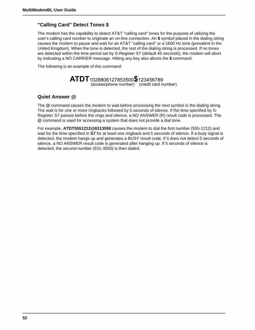
52
MultiModemBL User Guide
"Calling Card" Detect Tones $
The modem has the capability to detect AT&T "calling card" tones for the purpose of utilizing theuser's calling card number to originate an on-line connection. An $ symbol placed in the dialing stringcauses the modem to pause and wait for an AT&T "calling card" or a 1600 Hz tone (prevalent in theUnited Kingdom). When the tone is detected, the rest of the dialing string is processed. If no tonesare detected within the time period set by S-Register S7 (default 45 seconds), the modem will abortby indicating a NO CARRIER message. Hitting any key also aborts the $ command.
The following is an example of this command:
�������������6�77�����7�6�� ��%%���"�)�'� '�&���# �%����� %��� '�&���#
Quiet Answer @
The @ command causes the modem to wait before processing the next symbol in the dialing string.The wait is for one or more ringbacks followed by 5 seconds of silence. If the time specified by S-Register S7 passes before the rings and silence, a NO ANSWER (R) result code is processed. The@ command is used for accessing a system that does not provide a dial tone.
For example, ATDT5551212@6313550 causes the modem to dial the first number (555-1212) andwait for the time specified in S7 for at least one ringback and 5 seconds of silence. If a busy signal isdetected, the modem hangs up and generates a BUSY result code. If it does not detect 5 seconds ofsilence, a NO ANSWER result code is generated after hanging up. If 5 seconds of silence isdetected, the second number (631-3550) is then dialed.
53
Chapter 5 - Command Mode
5.4.3 Phone Number Memory Commands
Storing Phone Numbers D...N
A telephone number and command line of up to sixty characters may be stored in the modem’snumber memory. As many as ten of these numbers may be stored. Each number will be given aname, using the codes N0, N1, N2 up to N9.
A phone number is stored by entering ATD, then the number as it would be dialed, along with any P,T, R, ; or comma characters, and then entering N followed by the number’s “name,” which would beany number from 0 through 9, and then hitting RETURN.
For example, the tone-dialed number 1-612-631-3550 would be stored as number N3 by enteringATDT16126313550N3 and RETURN. The number is not dialed with this store command. Afterstoring a number, check to see that it has been stored correctly by typing ATL and hitting RETURN.
When phone numbers are stored, the entire command line is also stored so that you can effectivelycreate a macro for each number. For example, if you know a particular number needs to haveextended result codes, detect busy or dial tone, error correction, Xon/Xoff flow control, pacing, anddata compression enabled, the command line would be:ATX4&E1&E5&E13&E15DT16126313550N3. This would store the entire command at location N3.
Number Linking NN
You may command the modem to dial another number automatically if the first number dialed isbusy. This would be useful in a situation where a computer can be accessed through more than onephone number. This is called “linking”.
To link the number in N1 to the number N2, simply enter ATN1N2 and hit RETURN. Several numberscan be linked in the same command. For example, you could link N1 to N2 to N3 to N4 by enteringATN1N2N3N4 and RETURN or you could link N1 to N2 and back to N1 and then back to N2 byentering ATN1N2N1N2 and RETURN.
The only limit on the number of numbers that can be linked is the 60 characters allowed in acommand line. Number linking can not be used with blind dialing, since busy signals would not bedetected. You would have to select the Wait-for-Dial tone dialing method using the X Command inorder to use the Number Linking feature.
Listing Numbers Stored in Memory L
Telephone numbers that you have stored in the modem’s memory may be listed and displayed withthe L command. It will display all ten stored N numbers in a format like that shown below. All digitsand command letters will be shown. The number’s “name” (0 thru 9) is shown first, followed by thecomplete dialing command and telephone number as originally entered.
Simply enter ATL and hit RETURN to display these numbers on your video screen or printer. Anexample of an L command listing is shown below:
0 DT140823456781 DT16125551212;2 DP9,T140898765433 DT3738315,12101,161263135504 DT6313551R56 DP9,425851378 DTX4&E1&E5&E13&E15DT161263135509 DT12138880123
54
MultiModemBL User Guide
5.4.4 Configuration and Default Storage Commands
Store Configuration & S-Register Parameters in Non-Volatile Memory &W
The modem can store configuration parameters and S-Register values in its nonvolatile read/writeRandom Access Memory (RAM) memory. The &W command does this, which prevents any re-configuration from being lost on a power-down or Reset (ATZ) condition.
&W0 (or AT&W) causes the modem to store your customized AT command settings and S-Registervalues in its nonvolatile RAM. &W0 also sets the modem so that it reads your customized settingsstored in nonvolatile RAM when powered down or reset. (The &W0 command only changes thesettings stored in nonvolatile RAM that you specifically intend to alter. All other default parametersare applicable.)
&W1 causes the modem not to store your customized settings to nonvolatile RAM so that, afterpowering down or resetting the modem, it reads the factory default settings stored in ROM.
Loading Factory Defaults &F
The &F command provides a choice between customized configuration settings in RAM and thefactory default configuration settings in ROM. The &F8 and &F9 commands define the function of the&F command.
The modem is shipped from the factory with a pre-configured set of command and S-Register defaultsettings. This set of factory defaults can be recalled by issuing the &F command.
In addition to being able to recall the factory-installed defaults, the &F command can also recall thosedefaults stored under &W0.
This is done using the &F9 command. If you have stored parameters with the &W0 command andwish these settings to always be used as your defaults, you would enter &F9&W0.
To return the &F command to read factory installed defaults, enter &F8&W0. &F8 is the factorydefault.
Many datacomm program issue the &F command automatically- the &F9 command allows the userto select their own factory defaults. Note that the &F8/&F9 commands should be used with &W0.
Following is a summary of how the &F and Z reset commands interact with the &W command; notehow the &F reset command operates differently from the Z reset command:
Previous Command AT&F Power-On and ATZ
AT&W1 (default) ROM ROMAT&W0 ROM NVRAMAT&F8&W0 ROM NVRAMAT&F9&W0 NVRAM NVRAM
Modem Reset Z
The Z command can be used to reset the entire Command Mode buffer and the result is the same asif you had disconnected, and then reconnected power to the modem. When an ATZ command isexecuted, the state of the &W command determines where the default values originate. &W0 defaultscome from RAM and &W1 defaults come from ROM.
55
Chapter 5 - Command Mode
Unix UUCP Spoofing $SP
The modem can be configured in a Unix environment that employs ACK flow control as a means ofmonitoring data integrity. The modem can do “UUCP spoofing”, where the modem is able to generateACKs at the DTE interface. Data is transmitted more time efficiently because the delay of waiting fordata to be received, then for an ACK to be returned at the remote end, is eliminated. The $SP1command enables UUCP spoofing and the default command $SP0 disables UUCP spoofing.
Async/Sync Mode Switching &M
This command can be used to set the on-line mode to either synchronous or asynchronous. AT&M0will set the modem to Asynchronous mode, and all communications will be Asynchronous, in bothOn-line and Command modes. AT&M1 causes the modem to communicate asynchronously when inCommand mode and switch to synchronous mode while on-line. The modem defaults to &M0(asynchronous communications) on reset or power-up.
Synchronous Transmit Clock Select &X
The &X command selects the Synchronous Transmit Clock Source in conjunction with DIP-Switch#11. DIP-Switch #11 in the UP position enables External clocking. DIP-Switch #11 in the DOWNposition enables Internal clocking (default position). External clocking is when the DTE providestransmit clocking to the modem on pin 24 of the RS-232C interface.
&X0 is the default setting, which allows DIP-Switch #11 to control Internal/External Clocking (defaultInternal). Internal clocking is when the modem provides transmit clock to the DTE on pin 15 of theRS-232C/V.24 interface. The &X1 command overrides DIP-Switch #11 and selects External clocking.If DIP-Switch #11 is UP (External clocking), you can not override Internal clocking. &X2 enablesSlave Clocking. The &X2 Command causes the modem to generate the transmit clock timing (pin 15)from the receive clock (pin 17) from the DTE (therefore 15 and 17 are the same). In this mode (SlaveClocking), all timing is controlled by the receive clock.
56
MultiModemBL User Guide
5.4.5 Command Response (Result Code) Commands
Echo Command Mode Characters E
If the modem is connected to a full-duplex computer, it may be necessary for the modem to beconfigured to echo back characters entered while in the Command Mode in order for them to bedisplayed. The E command is used to configure the Command Mode echo, with ATE0 disabling theecho and ATE1 enabling the echo (default).
Result Codes Enable/Disable and No Response Answer Q
The Q command enables or disables Result Codes and the No Response Answer mode of operation.Result Codes may be disabled altogether in certain applications, such as computer-controlled autodialing, using the Q command. ATQ1 disables Result Code transmissions. ATQ0 (or ATQ) enablesResult Code transmission.
Regarding No Response Answer, you may want the answer mode handled without responses andecho turned off, but want the originate mode still intelligent. This is called the No Response Answermode. ATQ2 selects the No Response Answer mode. If you do not select any mode, the factorydefault setting (enable Result Codes) is automatically selected.
Result Codes ("Multi-Tech" or "Standard AT") &Q
The modem gives you a choice between the Multi-Tech Result Codes, and Result Codes that moreclosely match the standard AT command set responses (see Section 5.3).
AT&Q1 selects AT responses with no Reliable/Compression modifiers. With this command, theterse result code for CONNECT 2400 is 10.
AT&Q0 selects Multi-Tech responses with Reliable/Compression modifiers. With this command, theterse result code for CONNECT 2400 is 9.
Result Codes (Verbose/Terse) V
The V command controls whether the modem’s result codes are displayed as word (“verbose”) orsingle digit (“terse”) messages.
For example, if after dialing, no carrier signal is detected, the resulting message can be displayedeither as NO CARRIER, or as the digit 3.
Entering ATV0 (or ATV) causes the modem to display the Result Codes as digits, while ATV1displays them as words. If you do not select a method, the factory default setting causes the modemto display Result Codes as words.
57
Chapter 5 - Command Mode
Result Codes (Basic and Extended) and Call Progress Selection X
The X Command is used to select one of two possible dialing methods (“dumb” or “smart”), and toselect various response combinations related to these methods. You can choose to have certainresponses suppressed, or whether or not you want speed indications along with the CONNECTresponses. You can also pick and choose certain responses in order to match up with “Standard AT”responses. (Refer to Appendix G for a summary of Result Codes.)
The modem provides “Basic” and “Extended” Result Code sets. The difference between the two isthe Basic set provides one response (CONNECT) to indicate a connection, while the Extended setprovides several responses for different speeds (CONNECT, CONNECT 2400, CONNECT 4800,CONNECT 9600, Etc.).
When the Extended set is chosen, you also have the option of matching them up with Standard AT2400 response code sets, by including or not including the BUSY and/or NO DIAL TONEresponses while excluding the DIAL TONE response. The X command is used to select whichresponses are provided.
Regarding the modem’s method of dialing, the modem can detect standard dial tones and busysignals. This capability (“smart dialing”) allows the modem to wait for a dial tone, and when one isdetected, to begin dialing immediately.
The modem also can detect a distant busy signal, if after dialing, it reaches a busy number. This isuseful because it allows the modem to immediately abandon a call, rather than wait 45 seconds for acarrier signal that will never come. S-Register S7 defines the wait for carrier time (refer to Chapter 6).
The modem gives you a choice between the wait-for-dial-tone (“smart”) method we just described,and blind (“dumb”) dialing, where instead of detecting actual dial tones, the modem relies on timedpauses. When the wait-for-dial-tone method is chosen, the busy signal detection capability is alsoactivated. The X command is also used to select which dialing method is used.
Five different X commands are available (X0 through X4), with five different effects on the modem’sResult Codes.
X0 Provides the basic (short) result codes and provides “dumb” dial capabilities.
X1 Provides the extended result codes and provides “dumb” dial capabilities.
The remaining X commands affect Call Progress, and turn on Extended Result Codes.
X2 Looks for dial tone only and will not provide a busy response.
X3 Looks for busy only and not look for dial tone.
X4 Looks for dial tone and for busy.
The factory default setting is X0, which selects Basic Result Codes and the blind (“dumb”) method ofdialing.

58
MultiModemBL User Guide
5.4.6 Phone Line Conditioning Commands
Guard Tones (Not Used in BLI or BLK Models) &G
The &G command is used to control the presence or absence of guard tones from the transmitterwhen in Answer mode, at either 1200 or 2400 bps. Guard tones are used in Europe and other areasfor the modem to function in the telephone systems. Guard tones are not used in the United States.&G0 (default), turns off CCITT guard tones. &G1 turns on 550 Hz guard tones. &G2 turns on 1800Hz guard tones. This command is not used in international models.
Bell/V.21 Tone (Not Used in BLK Models) B
The B command selects the frequency that the modem uses for its answer tone. (The answer tone isthe tone transmitted by a modem receiving a call to the modem that called it, which initiates thehandshaking between the two modems.) At higher speeds there is no conflict, because all use CCITTfrequencies. At lower speeds (0-1200 bps), in the U.S., some modems use the Bell frequency of2225 Hz. However, the CCITT specification for V.22 has an answer tone frequency of 2100 Hz.
The ATB0 command enables CCITT frequencies including V.21 (300 bps) and V.23 (1200/75 bps).The ATB1 command enables Bell frequencies including Bell 103 (300 bps). The modem default isATB0. This command is not used in BLK models.
Phone Line Monitoring Speaker M
The modem has an internal on-board, speaker which functions like the speaker in a telephonehandset to enable you to monitor phone line activity. The M command can be used to determinewhen the speaker is operational.
Entering ATM0 disables the speaker completely, while ATM1 causes the speaker to be on only untila carrier signal is detected. ATM2 causes the speaker to remain on at all times. ATM3 causes thespeaker to be on during dialing and off during handshake. ATM1 is the default setting, and the onethat should be used in most applications.
Enable or Disable Recognition of Remote Digital Loop Signal &T
The modem has several self-test features (covered in Chapter 8). The tests are activated withdifferent U commands, such as ATU1, and so forth. The &T command is a phone line conditioningcommand that enables or disables the modem’s ability to recognize the Remote Digital Loop (RDL)test signal.
The AT&T4 command lets the modem respond to a RDL signal, and places itself in digital loop. TheAT&T5 command causes the modem to ignore the RDL signal. The factory default is &T5.
Enable/Disable Trelis Coded Modulation #T
This command enables or disables the Trellis Coded Modulation of the modem. There is usually noneed to disable (turn off) Trellis codings except under an unusual line condition called impulse noise.AT#T0 turns Trellis coding off and AT#T1 turns Trellis coding on (factory default).
59
Chapter 5 - Command Mode
Fallback Modes When On-Line #F
If line conditions deteriorate, the modem automatically drops its transmission speed (“fallback”). The#F command controls the different ways the modem falls back. During operation, if the error ratebecomes too great, the modem performs a retrain. If after the retrain, the error rate is still too high for33600 bps (19200 bps for 1932 models, 14400 bps for 1432 models) operation, the modem initiates aretrain at 4800 bps. If after the first retrain the modem returns on line at 33600 bps (19200 bps for1932 models, 14400 bps for 1432 models), the modem then starts a counter and a timer. If threeretrains occur within a two minute period, the modem falls back to 4800 bps.
Entering AT#F0 (or AT#F) allows no fallback when on-line.
AT#F1 allows the modem to fallback (based on the error rate or if three retrains have occurred withina two minute period) from:
2834 Series: 33.6K to 31.2K to 28.8K to 26.4K to 24K to 21.6K to 19.2K to 16.8K to 14.4K to 12Kto 9.6K to 4.8K bps.
1932 Series: 19.2K to 16.8K to 14.4K to 12K to 9.6K to 4.8K bps.
1432 Series: 14.4K to 12K to 9.6K to 4.8K bps.
The AT#F2 command enables incremental fall back, but also enables incremental fall forward if thephone line improves. AT#F2 is the factory default setting.
Enable/Disable Lowspeed Fast Connect $FC (2834 Series only)
Entering AT$FC0&W0<CR> sets up the data pump so that it will not transmit a 5 second 2100 Hzsignal. Entering AT$FC0&W0<CR> allows the modem to transmit a 5 second 2100 Hz signal and isthe factory default.
Cleardown at Disconnect &CD (2834 Series only)
The &CD command is used for control of cleardown at disconnect in V.32, V.32bis, V.34 and V.34enhanced modes.
A cleardown usually adds 1-2 seconds to the time it takes for the modem to go on-hook after adisconnect. A cleardown makes a disconnect by the remote modem easier to detect and asubsequent re-connection more likely. Enter AT&CD0&W0<CR> to execute a cleardown atdisconnect (default); and enter AT&CD1&W0<CR> to disable the cleardown function.

60
MultiModemBL User Guide
Auto Speed Detect #A
The function of the #A command is to detect and select the operational data rates (the “starting”speeds) with which the modem uses for initial handshake and speed selection.
Remember, this command does not control the originating data rate of the modem (that is done bythe Modem Baud Rate command $MBn), but only the Answer mode “starting” speeds.
Entering AT#A0 (or AT#A) causes the modem to operate starting at:
2834 Series: 33,600 bps, with fallback to 28,800 to 19,200 to 14,400 to 9600 to 4800 to 2400 to 1200and to 300 bps.
1932 Series: 19,200 bps, with fallback to 14,400 to 9600 to 4800 to 2400 to 1200 and to 300 bps.
1432 Series: 14,400 bps, with fallback to 9600 to 4800 to 2400 to 1200 and to 300 bps.
Entering AT#A1 causes:
2834 Series: 33,600 bps operation only.
1932 Series: 19,200 bps operation only.
1432 Series: 14,400 bps operation only.
Entering AT#A2 causes the modem to operate at starting speeds of:
2834 Series: 33,600 bps, with incremental fallback to 28,800, 19,200, 14,400, 9600 and 4800 bps.
1932 Series: 19,200 bps, with incremental fallback to 14,400, 9600 and 4800 bps.
1432 Series: 14,400 bps, with incremental fallback to 29600 and 4800 bps.
The AT#A3 command causes the modem (all models) to begin operation as a V.22bis modem at2400 bps, with fallback to 1200 to 300 bps. AT#A0 is the factory default value.

61
Chapter 5 - Command Mode
5.4.7 RS-232C Interface Control Commands
Carrier Detect Control &C
The &C command allows you to control the status of the Carrier Detect signal (CD-Pin 8) on the RS-232C line. You have four choices.
You can force the signal high, or allow it to act normally, or force the modem to reset when CD drops,or set it to stay high until the modem disconnects, go low momentarily, and then go high again. Thelast option is useful with some CBX phone systems and mainframe front ends, which require CD toact in this manner.
To allow CD to act normally, enter the command AT&C1 (the factory default setting). To force CD on,enter AT&C0. To reset the modem to its current parameters when CD drops, enter AT&C4. To setup CD so that it drops for one second on disconnect and then comes up again, enter AT&C2. (If youwant the drop time to be something other than one second, use S-Register S24 to change this value.Refer to the Chapter 6 instructions for S24.
Data Terminal Ready Control &D
Data Terminal Ready (DTR) on pin 20 of the RS-232C interface is required in order for the modem tooperate. A high DTR signal tells the modem that the device to which it is connected is active, or"ready" to communicate through the modem. If the signal is not being provided on the RS-232Cinterface, you can force DTR high with DIP-Switch #1 (Chapter 9).
DTR has some other modem functions. DTR can be used to trigger a dialing sequence, called DTRDialing. The condition of DTR can also be used to cause the modem to reset to its defaultparameters, just as if you had given the modem an ATZ command. To do this, enter the commandAT&D3 and hit RETURN.
The modem will now reset itself whenever DTR is dropped from On to Off, and will also go on-hook(hang up) if it is on-line.
Entering AT&D0 or AT&D causes the modem to ignore DTR. Entering AT&D1 causes the modem togo on-hook (hang up) with loss of DTR. The modem enters Command mode when DTR goes highagain. Auto-answer is disabled while DTR is low. Entering AT&D2 causes the modem to go on hookwith loss of DTR. The modem enters command mode when DTR goes high again.
CTS Control &R
The &R command allows you to control the Clear to Send signal (CTS-Pin 5) on the RS-232Cinterface. You have three choices. You can force the CTS signal high, allow it to act normally, or set itto stay high until the modem disconnects, go low momentarily, and then go high again. The lastoption is useful with some CBX phone systems and mainframe front ends, which require CTS to actin this manner.
To allow CTS to act normally, enter the command AT&R0. To force CTS on, enter the commandAT&R1 (this is the factory default setting). When the modem goes on-line, CTS still provides flowcontrol. To set up CTS so that it drops for one second on disconnect and then comes up again, enterthe command AT&R2. (If you want the drop time to be something other than one second, use S-Register S24 to change this value. Refer to Chapter 6).

62
MultiModemBL User Guide
Data Set Ready Control &S
The &S command allows you to control the status of the Data Set Ready signal (DSR - pin 6) on theRS-232C interface. You have three choices. You can force the signal high, allow it to act normally, orset it to stay high until the modem disconnects, go low momentarily, and then go high again. The lastoption is useful with some CBX phone systems and mainframe front ends, which require DSR to actin this manner.
To allow DSR to act normally, enter the command AT&S1 (the default setting). To force DSR on,enter the command AT&S0. To set up DSR so that it drops for one second on disconnect and thencomes up again, enter AT&S2. If you want the drop time to be something other than one second, useS-Register S24 to change this value (Refer to Chapter 6).
CTS/RTS Interaction Control &RF
In typical operation, Clear to Send follows Request to Send when the modem is on-line. In otherwords, if RTS goes off, CTS goes off in response. The &RF0 command enables CTS to follow RTS.In some applications, however, it may be necessary for CTS to operate independent of RTS. &RF1allows CTS to operate independently regardless of the state of RTS, and is the factory default. If thisis the case, refer to the &R command for control of the Clear to Send signal.
DSR/CD Interaction Control &SF
In typical applications, Data Set Ready (DSR) follows Carrier Detect (CD). &SF0 enables DSR tofollow CD, and is the factory default. &SF1 enables DSR to operate independent of CD. If this is yourapplication, refer to the &S command for control of the Data Set Ready signal.

63
Chapter 5 - Command Mode
5.4.8 Error Correction Commands
You can use AT commands to place your modem one of three V.42 (error correction) modes ofoperation. These are the Normal, Auto-Reliable, and Reliable modes.
Normal Mode &E0
In Normal mode of operation, the modem’s V.42 error correction capabilities are disabled, and themodem functions as a non-error-correcting modem.
Auto-Reliable Mode &E1
In Auto-Reliable mode during the handshaking procedures at the start of the on-line connection, themodem automatically determines whether or not the modem with which it is communicating is usingV.42 error correction. If the modem determines that the other modem is using V.42, it switches itselfinto MNP or LAPM Reliable (V.42) mode and its error-correction capability is enabled. If it isdetermined that the other modem is not using V.42, the modem remains in Normal mode, withouterror correction. The default setting is Auto-Reliable mode (&E1).
The method the modem uses to determine if the modem it calls is a V.42 modem involves the use ofa “Link Request”.
When the modem is in Auto-Reliable mode and originates a call, it goes through normal handshakingprocedures just like any dial-up modem. After establishing the on-line connection, the modemtransmits a Link Request message to the answering modem. (The Link Request message isgenerally about 33 coded characters.) If the answering modem replies with an appropriate V.42acknowledgment response, the modem switches into Reliable mode. Otherwise it stays in Normalmode. This V.42 Link Request handshaking procedure generally takes about five seconds.
When operating in V.42 Reliable mode, the modem uses its memory, or buffer, to store data as it isreceived. During periods of error-caused retransmissions or compression slowdowns, this buffer mayfill up. To prevent buffer overflow and subsequent loss of data, the modem uses "flow control" tosignal the computer attached to its RS-232C port that the modem buffer is close to being full. Thiscauses the computer to pause in its data transmission until the modem is able to empty its buffersufficiently to accept more data, at which time the modem signals the computer that it may resumetransmission. (Flow Control is discussed in Section 5.4.9).
Reliable Mode &E2
In Reliable mode, the modem uses its V.42 error correction capabilities during all transmissions, andmust be connected to another modem with a similar protocol activated (MNP or LAP-M).

64
MultiModemBL User Guide
V.42 Mode Select #L
The V.42 standard implements both MNP Class 3 & 4 and LAP-M error correction methods. The V.42Mode Select command (#L) selects which type of error correction (MNP or LAP-M) your modemuses for transmissions.
The various #L command options are as follows.
#L0 Command The #L0 Command allows a pair of modems to negotiate which V.42mode (MNP or LAP-M) will be used in their transmissions.
Originate Mode
a. If both modems have LAP-M capability, the modems use LAP-Mmode.
b. If one or both modems do not have LAP-M capability and bothhave MNP, the modems use the MNP mode.
Answer Mode
a. The answering modem responds to either an MNP Link Requestor LAP-M Originator Detection Pattern (ODP) signal depending onwhich the originating modem issues.
#L1 Command The #L1 Command sets your modem to MNP error correction anddisables LAP-M. This command is for Originate mode only. InAnswer mode, the modem still accepts MNP or LAP-M.
#L2 Command The #L2 Command sets your modem to LAP-M error correction, anddisables MNP. This command is for Originate mode only. Answermode still accepts MNP or LAP-M.
#L3 Command In the prior commands, the modems use a two phase process toestablish a V.42 connection (detection to establish whether theremote modem is also error correcting, and then protocolestablishment to determine parameters and to establish the errorcorrection connection). If you know that the other modem is a V.42error correcting modem, and you wish to use LAP-M, the #L3command disables the detection phase and goes directly to protocolestablishment. Both modems must have #L3 in effect.
Auto-Reliable Buffering $A
In Auto-Reliable mode, the modem is given four seconds to establish a Reliable connection. After thisfour-second period, the modem drops to Normal mode. Any data which is received during this periodis typically discarded. The $A command can be used to cause the modem to buffer (save) data thatis received during this Auto-Reliable time-out period. This data will then be output by the modem afterthe CONNECT message.
AT$A0 = Discard data received during auto-reliable time period.
AT$A1 = Buffer data received during auto-reliable time period.
The factory default is $A0.

65
Chapter 5 - Command Mode
Enable/Disable Auto Reliable Fallback Character $F
In Auto-Reliable mode, the modem is given four seconds to establish a Reliable connection. If asingle CARRIAGE RETURN is received from the remote modem during this four second period, theAuto-Reliable modem assumes that the remote modem is not in Reliable mode and drops to Normal(non-error correcting) mode. The CARRIAGE RETURN is the only character which causes themodem to drop to Normal mode. Any other character will either be buffered or discarded.
The $F command can be used to disable this fallback-to-Normal-due-to-CARRIAGE-RETURNfeature.
The Auto-Reliable fallback character ($F) and Auto Reliable buffering ($A) commands can be usedtogether to cause the modem to buffer all data received up until the CARRIAGE RETURN, and thendrop to Normal mode. All data received will then be output following the CONNECT message.
AT$F0 = Do not fall back to Normal if CARRIAGE RETURN received.
AT$F1 = Fall back to Normal mode if CARRIAGE RETURN received.
The factory default is $F0.
Retransmit Count $R
If errors are received during a Reliable connection, the modem re-sends the block of data whichcontained an error. With the $R0 command, if another error occurs, the block will be re-sent again.The modem counts the number of times that a data block is re-sent. If the same block of data isresent 12 times and still has not been received properly, the modem assumes that the transmissionline is unsuitable for transmission, and abort the connection.
This retransmit counter is disabled by the $R1 command. When the retransmit counter is disabled,the modem keeps trying to send data and will not abort, no matter how many times the same block isresent.
AT$R0 = Disconnect if retransmit count is exceeded.
AT$R1 = Do not disconnect due to retransmits.
The factory default setting is $R0.
V.42 Error Correction/300bps $E
At 300 bps, error correction is not typically used. $E1 lets the modem function at 300 bps in eitherNormal (&E0), Auto-Reliable (&E1) or Reliable (&E2) mode. $E0, which is the modem’s default,disables 300 bps/V.42 error correction altogether.
AT$E0 = No V.42 Error correction at 300 bps.
AT$E1 = V.42 Error Correction at 300 bps.
The factory default setting is $E0.

66
MultiModemBL User Guide
5.4.9 Flow Control Commands
Flow control refers to the techniques used by computer devices to stop and restart the flow of data toand from each other. Flow control is necessary so that a device does not receive more data than itcan handle. In the case of the MultiModem, there is a need for flow control in both directions. Asillustrated on the next page, flow control for data passing from your computer to the modem is calledModem-Initiated Flow Control and flow control for data passing from the modem to your computer iscalled Computer/Terminal-Initiated Pacing.
The MultiModem supports both hardware and software Modem Initiated Flow Control. On theComputer/Terminal-Initiated Pacing side, it supports hardware and software flow control, and aspecial version used by Hewlett-Packard compatible systems called ENQ/ACK Pacing. The modemallows hardware and software pacing to be passed through the modem to the other end of the link sothat your computer or terminal can control data start/stop activity through your modem.
This is called Xon/Xoff Pass-Through. To state it simply, “Flow Control” is something the modemdoes to the computer, while “Pacing” is something the computer does to the modem.
�����������
������������ ����������
*�&�������
���&�'������&
������� �
�������������� ����������������
����������� *�&�������
���&�'������&
������� �
Figure 5-2. Flow Control and Pacing
Hardware Flow Control &E4
With Hardware Flow Control, the modem uses its RS-232C interface to control the flow of data fromthe computer or terminal to which it is attached. The CTS (Clear to Send) signal on Pin 5 of the RS-232C interface is brought low to stop the flow of data, and is brought high to restart it. When youselect Hardware Flow Control as your Modem Initiated Flow Control method, you will also beselecting it for Pacing.
The difference between the two, however, is that Modem-Initiated Flow Control uses the Pin 5 CTSoutput signal, while Pacing uses the Pin 4 RTS input signal.
Modem commands are used to select the method of flow control used by the modem when its errorcorrection capabilities are used. These commands are covered in Section 5.4.9. If neither method isselected, the modem defaults to no flow control (&E3).
Xon/Xoff Flow Control &E5
Xon/Xoff is the most commonly used method of flow control. Under this method, control charactersknown as “Xon” and “Xoff” are inserted by the modem into the data to start and stop the flow of datafrom the computer or terminal to which the modem is attached. Xoff, which is a Control-S, stops theflow of data, and Xon, which is a Control-Q, restarts it. With regard to Binary Data, Xon/Xoff flowcontrol is not recommended because an Xoff character may be part of the data and would trigger anXoff of the modem or software package, which would halt data flow.
67
Chapter 5 - Command Mode
Xon/Xoff Pass-Through &E7
So far, you have had three choices to make regarding pacing:
1. You can set the modem to respond to Xon/Xoff pacing.
2. You can set the modem to respond to RTS pacing.
3. You can set the modem to ignore pacing completely.
Well, we’re not done with pacing yet. There’s another choice you can make (which actually can applyto both pacing and modem-initiated flow control, although it applies mainly to pacing) and that issomething called Xon/Xoff Pass-Through.
This means that if your modem is set to respond to Xon/Xoff commands, you can have the modemdo one of the following:
1. The modem responds to the Xon and Xoff pacing commands while at the same time allowingthese commands to pass through the modem and on to the remote location. We call this“Respond, Pass-Through”.
2. The modem responds to Xon/Xoff pacing, but does not allow the pacing signals to pass throughthe modem and on to the remote location. We call this “Respond, No Pass-Through”.
When Xon and Xoff commands are allowed to pass through the modem, the computer or terminal atthe remote site will receive these commands, and depending on how it is configured, the computer orterminal may respond to them also.
When two MultiModems are connected in Normal mode (not using error correction), Xon/Xoff can beused to control the flow of data between the modems. Flow Control can be turned on or off with theNormal Mode Modem Flow Control commands. When the modems are connected in Reliable mode,a different method of modem Flow Control is used, and the commands for Normal Mode ModemFlow Control are ignored.
When you are using Speed Conversion in Normal Mode, you must activate the modem’s NormalMode Modem Flow Control (Speed Conversion is explained in Section 5.4.11).
Send Xon/Xoff Characters #X
The #X phone interface command allows the modem to send either a single or multiple Xoffcharacters at the modem's buffer full level. When the modem’s buffer reaches it's "buffer full" level,the next character received causes another Xoff to be sent for every character subsequently receivedby the modem.
The AT#X0 command (factory default setting) causes one Xoff to be sent until the buffer reaches theXon level. The AT#X1 command causes an Xoff to be sent for every character received after themodem reaches its buffer full level.
Hewlett-Packard ENQ/ACK Pacing &E9
If the modem is being used with Hewlett Packard (or similar) equipment that employs ENQ/ACKpacing, the modem can be configured to respond to ENQ/ACK commands, making it compatible withHP systems. Doing so does not affect any other flow control or pacing already configured in themodem.
When configured for ENQ/ACK, the ENQ (Control-E) and ACK (Control-F) signals from the HPequipment will be accepted and responded to according to Hewlett-Packard protocol.
68
MultiModemBL User Guide
Normal Mode Modem Flow Control On &E11
When two MultiModems are connected in Normal mode (not using error correction), Xon/Xoff can beused to control the flow of data between the modems. Flow Control can be turned on or off with theNormal Mode Modem Flow Control commands. When the modems are connected in Reliable mode,a different method of modem flow control is used, and the commands for Normal Mode Modem FlowControl are ignored.
When you are using Speed Conversion in Normal Mode, you must activate the modem’s NormalMode Modem Flow Control (Speed Conversion is explained in Section 5.4.11).
Terminal/Computer Initiated Pacing &E13
As mentioned earlier, the modem can initiate flow control by issuing Xon/Xoff commands or togglingthe CTS signal on the RS-232C interface. The modem can also be configured to react to similarcommands and signals from the computer or terminal to which it is attached via the RS-232Cinterface. We refer to the computer or terminal initiated flow control as Pacing. When the modem isset for Pacing On, the modem will respond to the terminal or computer pacing. When the modem isset for Pacing Off, it will ignore pacing.
In order for the modem to be set for Pacing On, a modem-initiated method of flow control must bepreviously selected. Once this is done, the modem will respond to either Xon/Xoff commands, or tothe toggling of the RTS (Request to Send) signal on Pin 4 of the RS-232C interface, depending onwhat you selected earlier as your Modem-Initiated Flow Control method.
Maximum Block Size &BS
The maximum size of Reliable mode data blocks can be controlled with the &BS command. MNP 3sends blocks of 1 to 64 characters. MNP 4 and 5 typically send blocks of 1 to 256 characters andLAP-M typically send 128 characters. For MNP Classes 4 and 5/LAP-M, reducing the block size to64 characters may give a smoother flow of data, and better throughput on noisy phone lines. Usingsmaller block sizes over good phone lines may cause a slight loss in throughput (speed).
AT&BS0 = Maximum transmit block size of 64 characters
AT&BS1 = Maximum transmit block size of 128 characters (LAP-M) 256 characters (MNP)
The factory default setting is &BS1.
Parity Selection #P
The #P command enables the setting of parity. AT#P0 selects no parity. AT#P1 selects odd parity.AT#P2 selects even parity and is the default value. Note when setting up your data comm software, itis critical that both your remote and local system's parity selection be set identically.
AT#P0 = no parity
AT#P1 = odd parity
AT#P2 = even parity
The factory default setting is AT#P2.

69
Chapter 5 - Command Mode
5.4.10 Compression, Error Correction, Flow Control, Pass-Through and Pacing Commands
The modem has a variety of commands to control its error correction and data compression options.These additional commands are listed below. (Remember to precede each command with the ATcharacters.)
Normal/Auto-Reliable/Reliable Mode Commands:
&E0 = Normal Mode
&E1 = Auto-Reliable Mode*
&E2 = Reliable Mode
Modem-Initiated Flow Control Commands:
&E3 = Disables flow control (no flow control)
&E4 = Hardware flow control (CTS on/off and RTS on/off)*
&E5 = Xon/Xoff flow control
Xon/Xoff Pass-Through Commands:
&E6 = Modem responds to Xon/Xoff characters, but does not allow Xon/Xoff characters to passthrough to remote site.*
&E7 = Modem responds to Xon/Xoff characters, and allows them to pass through to remote site.
#X0 = Selects single Xoff character until Xon level returns*
#X1 = Selects multiple Xoff characters after buffer levels is full.
Enq/Ack Pacing Commands:
&E8 = Enq/Ack method of pacing off*
&E9 = Enq/Ack method of pacing on
Normal Mode Modem Flow Control Commands:
&E10 = Normal Mode Modem Flow Control off*
&E11 = Normal Mode Modem Flow Control (Xon/Xoff) on
Computer-or Terminal-Initiated Flow Control (Pacing) Commands:
&E12 = Pacing off*
&E13 = Pacing on (either RTS on/off or Xon/Xoff depending on the setting of &E4 or &E5).*
Data Compression Commands:
&E14 = Data Compression disabled
&E15 = Data Compression enabled*
*Factory Default setting

70
MultiModemBL User Guide
5.4.11 Speed Conversion Commands
Speed conversion is a necessary part of data compression since data must be presented to themodem faster than it can handle data, if data compression is to be effective.
Speed conversion allows the modem to communicate at one speed over the phone line, and atanother speed at the RS-232C interface. The speed (also referred to as “data rate” or “baud rate”)can be fixed at the RS-232 interface independently of the baud rate of the on-line transmissions.
In addition to data compression, another popular application for speed conversion involves an auto-answer MultiModem connected to a computer that does not have autobaud capability. This meansthat the computer must be set at a fixed baud rate, regardless of the baud rate that the modem iscommunicating over the phone line at. In this application, speed conversion allows the modem tomatch its speed to that of the calling modem, while at the same time communicating with theattached computer through its RS-232C port at a fixed baud rate, which can be pre-selected at 300,1200, 2400, 4800, 9600, 19,200, 38,400, 57,600 or 115,200* bps.
(* 1932 and 2834 models only)
Speed Conversion $BA
When using speed conversion, you must set the modem so that it does not adjust its speed at theRS-232C serial port, even if the modem does adjust its data rate. To turn Speed Conversion ON,enter the command AT$BA0 and hit RETURN.
To turn Speed Conversion OFF, enter AT$BA1 and hit RETURN. The modem will now match its RS-232C speed to that of the computer, and will adjust its speed to any changes in the computer’s speedin Originate mode, or to the speed of the originating modem in Answer mode. The speed at which themodem communicates over the phone line will always be the same as the speed at which itcommunicates via its RS-232C serial port.
Modem Baud Rate $MB
The $MB command presets the modem’s transmission baud rate for originate operations, (i.e., thespeed of the modem’s transmissions over the telephone lines when originating a call). With speedconversion, this transmission speed can be a different baud rate than the serial port speed.
When the modem receives (answers) a call from another modem, it automatically switches its phoneline transmission speed to match the calling modem. However, if the modem originates a call toanother modem that is unable to connect at the same baud rate, it automatically drops to a lowerbaud rate in an attempt to match the speed of that modem. For example, if the modem is set for14,400 baud and calls another modem that has a top speed of 2400 baud, it drops to 2400 baud.
The command to set the Modem Baud Rate is AT$MBn, where n can be:
2834 Series:
AT$MB75 = CCITT V.23AT$MB300 = 300 bpsAT$MB1200 = 1200 bpsAT$MB2400 = 2400 bpsAT$MB4800 = 4800 bpsAT$MB9600 = 9600 bpsAT$MB14400 = 14400 bpsAT$MB19200 = 19200 bpsAT$MB28800 = 28800 bpsAT$MB33600 = 33600 bps
The factory default is 33600 bps.
71
Chapter 5 - Command Mode
1932 Series:
AT$MB75 = CCITT V.23AT$MB300 = 300 bpsAT$MB1200 = 1200 bpsAT$MB2400 = 2400 bpsAT$MB4800 = 4800 bpsAT$MB9600 = 9600 bpsAT$MB14400 = 14400 bpsAT$MB19200 = 19200 bps
The factory default is 19200 bps.
1432 Series:
AT$MB75 = CCITT V.23AT$MB300 = 300 bpsAT$MB1200 = 1200 bpsAT$MB2400 = 2400 bpsAT$MB4800 = 4800 bpsAT$MB9600 = 9600 bpsAT$MB14400 = 14400 bps
The factory default is 14400 bps.
72
MultiModemBL User Guide
Serial Port Baud Rate $SB
The $SB command presets the speed of the modem’s serial (RS-232C) port, in both Originate andAnswer modes. Speed conversion allows you to set this serial port baud rate at a fixed speed of up to115,200 bps for 1932 and 2834 models, and 57600 bps for 1432 models, regardless of the modem’stransmission speed setting.
In order for this command to be effective, the modem’s Speed Conversion feature must first beturned off with the $BA command. When Baud Adjust is on, the modem automatically adjusts itsserial port baud rate to match the speed of the computer or terminal it is connected to, as soon as itreceives its first AT command. However, in many applications, such as automatic answer, themodem may not receive AT commands, in which case it is very useful to be able to preset the serialport baud rate with this $SB command.
In addition to setting the modem’s serial port speed, this command also sets the speed at which themodem issues Command mode responses.
The modem will accept AT commands at any speed, regardless of the speed preset by the $SBcommand. If the modem receives such a command at a speed that is different than the preset speed,the modem switches its serial port baud rate to match the new AT command speed, although thebaud rate value stored by the $SB command remains the same. This provides you with a convenientway to switch the serial port speed, and still make it easy to go back to the original speedautomatically the next time the modem is powered up or reset with an ATZ command.
The command to set the Serial Port Baud Rate is AT$SBn, where n can be:
AT$SB300 = 300 bpsAT$SB1200 = 1200 bpsAT$SB2400 = 2400 bpsAT$SB4800 = 4800 bpsAT$SB9600 = 9600 bpsAT$SB19200 = 19,200 bpsAT$SB38400 = 38,400 bpsAT$SB57600 = 57,600 bpsAT$SB115200 = 115,200 bps*
The factory default is 57,600 bps.
(* 1932 and 2834 Series only)
Note: Some serial ports, particularly those in older PC-compatible computers, may limit theperformance of a higher speed modem like the MultiModem (see Chapter 3). The limiting factor is acircuit called a Universal Asynchronous Receiver/Transmitter, or UART. All data from your modemflows through it. 8250, 16450, and 16550 are UARTs typically used in PC-compatible computers. The8250 is unreliable above 9,600 bps and the 16450 is unreliable above 19,200 bps. The 16550 UART,however, is reliable to at least 115,200 bps. With V.42bis data compression enabled, the MT2834BLcan achieve throughputs approaching 115.2K (depending on line quality and file content). If youpresently do not have a 16550 UART in your PC, we recommend that it be replaced with a Multi-Techhigh speed Intelligent Serial Interface (ISI) card. It comes in one, two and eight-port versions forDOS/Windows and UNIX systems, and includes a 32 K buffer that eliminates data loss even at highspeeds. See your dealer for details.

73
Chapter 5 - Command Mode
5.4.12 Immediate Action Commands
Help Screens $H
The Help command is designed to give you short explanations on how to use each modemcommand. The Help command can be quite useful if your manual is not handy and you are in themiddle of a communications session. Although the explanations are quite abbreviated compared tothose in this manual, they should prove to be helpful reminders when needed.
At the time of this writing, we have three screens of Help information (Screen #1, #2 and #3), andmore screens may be added in the future. The Help commands are structured so that you can call upone of three Help screens, as follows:
AT$H1 = Help Screen #1
AT$H2 = Help Screen #2
AT$H3 = Help Screen #3
Inquiry for Product Code I
Some systems or software packages automatically check the “identification” of the modem with whichthey are communicating, by using the I command. This “read” command lets the software todetermine the type of modem with which it is communicating.
When ATI or ATI0 is entered, the modem responds with 247. When ATI1 is entered, the modemresponds with a three-digit code indicating the firmware version number. When ATI2 is entered, themodem responds with MT2834BL, MT1932BL or MT1432BL depending on model.
Windows 95 Autodetect Inquiry I9 (2834 Series only)
This read command permits a Windows 95 operating system to query the MT2834BL'scharacteristics. When ATI9<CR> is entered the symbols BL 28800 FAX CT are displayed; whichindicates to the Windows 95 system that your particular modem is a MT2834BL, 28,800 bps, faxClass 2 capable modem. With autodetect support in your MT2834BL, your PC can automaticallyallocate resources and configure it and other devices. The MT2834BL implements autodetectcapability in the form of a single .INF (Information) file that specifies AT Command mode and ResultCode "Registry Keys" that are specific to your MT2834BL.
Listing Current Operating Parameters L5 L7
The L5 and L7 commands list the current operating parameters of your modem. This information canbe very useful when you are changing communications software or when you are changing modemdefault settings.
The command to list the modem’s current operating parameters is ATL5 for the basic parameters.Entering ATL7 lists additional parameters on the modem.
Listing S-Register Values L6
Entering ATL6 lists the current values stored in the modem’s S-Register. This information can bevery useful if you wish to change S-Register values. (Refer to Chapter 6 for more information on S-Registers).

74
MultiModemBL User Guide
Listing On-Line Diagnostics L8
The L8 command displays the current on-line CONNECT status of the modem. This display can beprinted and used as a modem status report or as diagnostic information (such as when calling TechSupport). To activate this command first type +++AT<CR>(on-line escape command whilemaintaining command mode), then type ATL8. What then displays on your monitor is your modem'scurrent on-line condition (e.g., Link Type, Line Speed, Serial Speed, Type of Error Correction/DataCompression, Number of past Retrains, etc.).
Off Hook H
You can make the modem hang up (go On Hook). Entering ATH1<RETURN> brings the line OffHook, just as if you picked up the telephone set. You can hang up by entering ATH0 or ATH (thedefault is 0 when no number is entered).
Escape Sequences- Entering Command Mode While Still On-Line +++AT<CR>
It is possible to cause the modem to enter Command mode after the modem has gone on-line with aremote modem, without disconnecting the call. This is done by entering an Escape Code. The defaultEscape Code used by the modem is three plus signs (+++) followed by the letters A and T, up tosixty command characters (most typically “H”, to hang up), and a RETURN. The number ofcommand characters allowed after +++ AT<CR> , is defined by S-Register S34. S-Register S34defaults to ten command characters.
When this is done, the modem escapes to Command Mode, executes the command (if any), andthen remain in Command mode. For example, to hang up the modem at the end of a call, enter+++ATH and hit RETURN. There is no need to incorporate pauses before and after the plus signs,as done in earlier modems.
BREAK AT<CR>
The modem provides an alternative Escape method, using a Break signal as the Escape Code. TheBreak signal allows the start-stop DTE (data terminal equipment) to signal the modem without loss ofcharacter transparency. With this method, a BREAK signal is used instead of the three plus signs.The BREAK is followed by the letters A and T, up to 60 command characters, and RETURN. Whenthis is done, the modem executes that command, but remains in On-Line mode unless the commandwas to hang up and/or reset the modem (an H or Z), in which case the modem would be in theCommand Mode after executing that command.
Escape Sequence Options - Entering Command Mode While On-Line %E
As mentioned, the default escape sequence setting is for the modem to respond to the +++ escapemethod. Optional settings are for the modem to respond to the Break method, for the modem torespond to either the +++ or the Break Methods, for the modem to ignore both methods and notescape, for the modem to respond with no "OK" to +++, and for the modem to respond with "OK" to+++. The %E command is used to select these options, as follows:
%E0 = Modem Won’t Escape
%E1 = +++ AT<CR> Method (default)
%E2 = Break Method
%E3 = Either +++ or Break Methods
%E4* = No "OK" Response to +++
%E5* = "OK" Response to +++
* The %E4 and %E5 commands enable or disable an "OK" response, which is required by somesoftware packages during an escape sequence.

75
Chapter 5 - Command Mode
Force Answer Mode A
You can force the modem into Answer mode with the modem’s A command.
Entering ATA when in Command mode immediately brings your modem off-hook, out of Commandmode and into On-Line Answer mode, and causes it to transmit its carrier signal over the phone line.If no responding carrier tone is received by your modem within forty-five seconds (or some other timeas determined by S-Register S7), your modem stops transmitting its tone, hangs up, and goes backinto Command mode.
Exiting Command Mode, Going Back On-Line O
You can bring the modem out of Command mode and back into On-Line mode by entering ATO(where O is the letter O, not the number 0). In this case, the O command reverses what was done byentering the Escape Code. The O command will bring the modem into the same On-Line mode(Originate or Answer) that it was in prior to going into Command mode.
5.4.13 Line Probe Commands (2834 Series only)
Before V.34 negotiation takes place, remote and local modems transfer their functional capabilitiesusing modulated calling and answering tones; indicating the common capabilities of the modem ateach end.
Once this is done, a probing signal is passed between the modems to identify impairments in thetelephone channel (e.g., Receive Signal Strength vs. Frequency, Noise vs. Frequency and Signal toNoise Ratio vs. Frequency). After receiving the results of the probing signal, the modem receiversand transmitters begin with the lowest speed and move up until reaching the highest speed at whichthey can exchange data. All this occurs in about five seconds.
There are a number of Line Probe Commands. These commands are configurable and can be storedto RAM (via AT&W0).
These commands are listed below.
Enable/Disable Reading of Line Probe Information Commands:
%DP0 = Do not read Line Probe information from DSP during handshake (Default).
%DP1 = Read Line Probe information from DSP during handshake.
Format of Line Probe (Graph or Table) Commands:
%DF0 = Data is displayed in Graph format. Y axis is shown in dBms (Default).
%DF1 = Data is displayed in Table format. Numeric values are displayed for 150Hz to 3750Hz in 75HZ increments.
Immediate Action Line Probe Commands:
To activate these commands first type +++AT<CR>(on-line escape command while maintainingcommand mode), then type the Command prefixed by an AT.
&RP = This command initiates a retrain that makes the processor read Line Probe information. Valid only when on-line in V.34 mode.
L9 = Displays Signal Strength information.
L10 = Displays Signal to Noise Ratio information (SNR).
L11 = Displays noise information.

76
MultiModemBL User Guide

Chapter 6 - S-Registers

78
MultiModemBL User Guide
6.1 Introduction
Certain Command Mode configurations are stored in memory registers called, S-Registers. The Scommand is used to assign a value to, and to read the current value of an S-Register. To assign avalue to an S-Register, enter the letter S, followed by the S-Register number and an equals sign (=),and then a decimal response to the message “ENTER THE NEW VALUE IN DECIMAL FORMAT”.To read an S-Register value, enter the letter S followed by the S-Register number and a questionmark (?), then hit RETURN. To verify that the S-Register value was entered correctly, enter forexample, ATS8? and hit RETURN. You should receive a response of the assigned value given tothat S-Register. Refer to Section 6.2, Reading and Assigning S-Register Values.
S0Number of Rings Until Modem Answers
Unit: 1 ringRange: 0-255Default: 1Description: S0 defines the number of rings the modem waits before answering an incoming call.
The default value is one ring (Decimal 1), which means that the modem answers thecall immediately after the first ring. The maximum number of rings that can beconfigured is 255. Setting the value to zero (0) disables auto-answer completely.
S1Rings Which Have Occurred
Unit: 1 ringRange: 0-255Default: 0Description: S1 counts the number of rings that have occurred. It is a “read” type of register and
is seldom, if ever, used in typical operation. Each time an incoming ring signal isdetected, S1 increases its value by one, up to a maximum of 255. If you set S1 to avalue other than its default value of zero, or if the value is increasing with rings, thisnew value remains stored in S1 for eight seconds after the last ring is counted, afterwhich time the value reverts to zero.
S2Escape Code Character
Unit: ASCII CharacterRange: 0-127Default: 43 (+)Description: S2 defines the escape code character. The default character is the plus (+) sign
(Decimal 43), but may be set for any ASCII character. Setting an S2 value greaterthan 127 results in no escape character, and therefore no means of enteringCommand mode from On-line mode without breaking the on-line connection.
S3Return Character
Unit: ASCII CharacterRange: 0-127Default: 13 (^M)Description: S3 defines the character recognized as Carriage Return (RETURN) or “Enter”. S3
may be set for any ASCII character.

79
Chapter 6 - S-Registers
S4Line Feed Character
Unit: ASCII CharacterRange: 0-127Default: 10 (^J)Description: S4 defines the character recognized as Line Feed. S3 may be set for any ASCII
character.
S5Backspace Character
Unit: ASCII CharacterRange: 0-127Default: 8 (^H)Description: S5 defines the character recognized as BACKSPACE. S5 may be set for any ASCII
character.
S6Wait Time for Dial Tone
Unit: 1 secondRange: 2-255, 4-255**, 4-7***Default: 2, 4**,4***Description: S6 sets the time the modem waits after the RETURN key is pressed before
executing a dial command. The default setting is two seconds (Decimal 2).
S7Time for Carrier (Abort Timer)
Unit: 1 secondRange: 1-255, 1-55*Default: 45, 55*Description: S7 defines the Abort Timer (lack of carrier) delay time. The default value is 45
seconds (Decimal 45). This means that, after dialing, the modem waits for a carriersignal for up to 45 seconds and, if none is detected, aborts the call. The maximumS7 value is 255.
S8Pause Time for Comma
Unit: 1 secondRange: 0-255, 4-255**, 4-7***Default: 2, 4**, 4***Description: S8 sets the length of the pause caused by a comma inserted in a dialing command.
The default setting is two seconds, (or two units Decimal 2) or four seconds, whereeach unit is one second. S8 may be set for up to 255 seconds.
S8 also sets the time the modem waits before retrying a call after detecting a busysignal. Some computer systems need more than two seconds to reset (in which caseyou should increase the value of S8).
* Value for International and DOC units** Value for International units only***BLK models only

80
MultiModemBL User Guide
S9Carrier Detect Response Time
Unit: 100 mSec.Range: 1-255Default: 6Description: S9 sets the time delay between when the modem first detects a valid incoming
carrier signal and when the modem turns on its Carrier Detect circuit. The defaultsetting is 600 milliseconds, or six units of 100 mSec each (Decimal 6). S9 may be setfor up to 25.5 seconds.
S10Carrier Loss Disconnect Delay Time
Unit: 100 mSec.Range: 0-255Default: 7Description: S10 sets the time a carrier signal must be lost before the modem disconnects. The
default setting is 700 mSec, or seven units (Decimal 7) of 100 mSec. Maximum delayis 25.4 seconds (Decimal 254). Setting the S10 value to 255 causes the modem tonot disconnect with loss of carrier. (This S-Register applies at speeds of 2400 bpsand less.)
S11Tone Dialing: Tone Spacing and Duration
Unit: 1 mSec.Range: 1-255, 80-255*, 80-255***Default: 70, 80*, 80***Description: S11 sets the speed of tone dialing (spacing and tone duration times). The default
value is 70 units (Decimal 7) or 80 units, where each unit is one mSec, meaning thateach tone is on for 70 mSec with a 70 mSec pause between each.
The minimum S11 value allowed by most telephone systems is 50 mSec (50 units).Very few telephone systems can handle anything faster than that. The maximum S11value is 255 mSec (255 units).
S13Remote Configuration Escape Character
Unit: ASCII CharacterRange: 0-127Default: 37 (%)Description: S13 defines the remote configuration escape character (which becomes your
modem’s remote configuration character). The default is three percent symbols(%%%). When the S13 character is entered three consecutive times from a remotelyconnected site, your modem responds with its Remote Configuration procedure.
* Value for International and DOC units** Value for International units only***BLK models only

81
Chapter 6 - S-Registers
S15Callback Time Delay
Unit: SecondsRange: 10-255Default: 20Description: S15 defines the time delay between Callback attempts after initial passwords have
been exchanged between modems. Refer to Chapter 7 for Callback Securityinformation.
S16Callback Attempts
Unit: 1 AttemptRange: 1-255, 1-2***Default: 4, 2***Description: S16 defines the number of attempts allowed after initial passwords have been
exchanged between modems.
S17Changing Break Time
Unit: 10 mSec.Range: 0-2.5 secDefault: 250Description: S17 defines the break time (space) sent to the local PC. The default is set for a 25 to
250 mSec break. The break time can be changed in 10 mSec increments byincreasing or decreasing the value of S17.
S18Automatic Leased Line Restoral
Unit: 1 minuteRange: 10-255Default: 30 minutesDescription: When the modem is in dial backup mode, it periodically checks the lease line to see
if it is operational and tries to restore the lease line if possible. S18 defines how oftenattempts occur. The default of S18 is 30 minutes and can be set in one minuteincrements from 10 to 255 minutes. Setting the S18 restoral under 10 minutescauses excessive breaks in dial-up operation.
S19Dial-Back Timer
Unit: 1 minuteRange: 0-255Default: 1Description: S19 is a timer that begins when the lease line goes down. S19 specifies the duration
of time the modem attempts to reestablish the lease line connection.
* Value for International and DOC units** Value for International units only***BLK models only

82
MultiModemBL User Guide
S24PBX/CBX Disconnect Drop Time for DSR/CTS/CD
Unit: 50 mSec.Range: 0-255Default: 20Description: Some PBX and CBX phone systems require the modem’s DSR, CTS, and/or CD
signal(s) to behave in a certain manner when calls are disconnected. The modem’s&R, &S, and &C commands cause the modem to drop these signal(s) for a specifiedtime period upon disconnect, and then bring the signal(s) up again. S24 defines thelength of time that the signals drop. The default setting of 20 results in a one seconddrop time, which is what most PBX/CBX systems with this requirement need.
S25DTR Dropout Time
Unit: 100 mSec.Range: 0, 1 through 255Default: 0Description: S25 defines the amount of time that DTR must be dropped before the modem
disconnects. Typically, a disconnect occurs when DTR is dropped for 50milliseconds or more. This dropout time can be increased, up to a maximum of 25.5seconds. The S25 unit value for zero is the default value of 50 mSec. For valuesfrom 1 through 255, the unit value is 100 mSec.
S26Failed Password Attempts
Unit: 1 failed attemptRange: 0-255Default: 0Description: S26 counts the number of times there has been a failed password attempt. For
example, if you entered ATS26? the message 003 would be displayed, meaningsomeone has failed three times to gain access to your modem using its passwordsecurity system.
S29Local Inactivity Timer
Unit: minutesRange: 1-255Default: 20Description: S29 defines the amount of idle time that can elapse between AT commands after the
SETUP password has been entered. If this timer expires, the LOGIN and SETUPpasswords will have to be re-entered. S29 only takes effect when the modem hasbeen sent a #DB1 command, which secures the modem from local and remoteconfiguration or dialing (i.e., no AT commands can be sent until the LOGIN andSETUP passwords have been entered).

83
Chapter 6 - S-Registers
S30Inactivity Timer
Unit: 1 min.Range: 0-255Default: 0Description: S30 causes the modem to disconnect if no data is transmitted or received for a
specified time. This timer runs during both Reliable and Normal error correctionconnections. The timer restarts any time a data character is passed through theserial port (either sent or received). If noise on the phone line causes an error to bereceived during Normal mode, this also restarts the timer. The default value is off (0).
The inactivity timer is disabled by setting S30 to 0, which is the factory defaultsetting.
S32Time Elapse for Escape Sequence
Unit: 1 secondRange: 0-255Default: 20Description: S32 sets the time period to validate the escape sequence. If the time interval expires
before the escape sequence is employed (by hitting RETURN), the escapesequence is aborted. The default is 20 units.
S34Buffer Length of Command Mode...After On-line Escape Sequence
Unit: ASCII CharacterRange: 0-60Default: 10Description: If the number of characters after AT exceeds the S34 buffer length value, the buffer
is cleared and the escape sequence is aborted.
S36Time Between DTR Inactive and Modem Off-Hook
Unit: 1 SecondRange: 0-255 secondsDefault: 0Description: The DTR Busy-out feature uses S-Register S36 to set the time between DTR
inactive (low) and the modem going off-hook. S36 can be set in one-second intervalsfrom 0 to 255 seconds. With the default setting of S36=0, DTR Busy-Out is disabled(i.e., DTR won't Busy-Out).
S37Time Between DTR Active and Modem On-Hook
Unit: 1 SecondRange: 0-255 secondsDefault: 5Description: S37 sets the time between DTR being active and the modem going on-hook (not
busy). S37 will only function in conjunction with S36.
84
MultiModemBL User Guide
S48Program V.34bis Connect Speeds (2834 Series only)
Unit: N/ARange: 33, 31, 28, 26, 24, 21,19,16,14,12, 96 and 48Default: 0Description: Defines which speed modem connects within the scope of Enhanced V.34 mode
(e.g., S48 = 26 means maximum connect speed is 26.4K). This registercompensates for line conditions that have trouble supporting higher Enhanced V.34speeds (e.g., 33.6K, 31.2K, 28.8K, 26.4K, 24K...). The modem default is a value of 0,which indicates a connection attempt of 33.6K.
85
Chapter 6 - S-Registers
6.2 Reading and Assigning S-Register Values
The S command is used to assign a value to, and to read the current value of, an S-Register. To readan S-Register value, enter the letter S followed by the S-register number and a question mark (?),then hit RETURN. For example, entering ATS7? and hitting RETURN displays the value of S-Register S7 in a 3-digit decimal form. The number 8 would appear as 008, the number 30 wouldappear as 030, and the number 255 would appear as 255.
To assign a value to an S-Register, enter the letter S followed by the S-Register number and anequals sign (=), and then a decimal response to the message “ENTER THE NEW VALUE INDECIMAL FORMAT”. Convert all ASCII characters to their decimal equivalents before entering them.S-Register decimal values range from 0-127 for ASCII characters, or 0-255 for numeric values. Acomplete ASCII conversion chart is located in Appendix B of this manual.
6.2.1 Examples of Assigning Values
1. Let’s say you wish to have longer pauses caused by the comma in a dial command; five secondsinstead of two. Entering ATS8=5 assigns 5 as the value for S-Register S8 (meaning the modempauses five seconds for a comma in a dial command).
2. In a second example, let’s say that you wish to configure the modem to answer incoming callsafter the 30th ring instead of after the first ring. To configure S-Register S0 with a value of 30,enter ATS0=30 and hit RETURN.
3. In a third example, let’s say you are calling long distance to another country code, and it is takinga long time to connect. The S-Register S7 (Abort Timer) setting of 45 seconds, is insufficient.The abort timer times out and cancels the call before a connection is made. To change the S7value to 55 seconds, enter Command mode, then enter ATS7=55 and hit RETURN. Now, afterdialing, the modem allows 10 more seconds for a carrier signal before aborting the call. Theadditional 10 seconds should provide enough time for international calls.
6.2.2 Examples of Reading Values
To verify that you entered the value correctly in the above examples, enter ATS8? and hit RETURNin the first example, ATS0? in the second, and ATS2? in the third example. You should receive theresponse 005 in the first example, 030 in the second example, and 055 in the third example.
When configuring the S-Registers, it is a good practice to include the verification read-entry in thesame command line as the configuration assignment-entry. In the three preceding examples, enterATS8=5S8?, ATS0=30S3?, and ATS7=55S7?.

86
MultiModemBL User Guide
6.3 AT Command and S-Register Summary
The vast majority of installations are similar, with the modem being used to dial up a remoteinstallation where the call is automatically answered. Your modem has a default configuration to dialanother modem that supports error correction, data compression and flow control. If the answeringmodem is not compatible, the MultiModem can match protocols, provided the protocols are industrystandard (i.e., ITU or Bell) and not proprietary.
The &W command, used in conjunction with specific other AT commands and S-Registers, can re-configure the modem to conform to a specific application. The command AT&W0 (or AT&W) causesthe modem to store its current parameters in its nonvolatile RAM. The command also sets themodem upon power up, or when it is reset with an ATZ command, the modem reads all of itsconfiguration and S-Register parameters from RAM, and not from the factory settings in ROM (noteyou may recall factory installed defaults by entering AT&F8&W0). The &W command changes theconfiguration parameters stored in RAM that you specifically intend to alter. All other defaultparameters remain unchanged.
The AT&W1 command sets the modem so that it does not store its parameters in RAM, and onpower up or when an ATZ command is issued, parameters are read from the factory default settingsin ROM.
Before using the &W command, you may want to view the modem's current operating parameters.Use the ATL5, ATL6 and ATL7 commands to display the current modem configuration.
Chapter 7 - Callback Security andRemote Configuration

88
MultiModemBL User Guide
7.1 Introduction
This chapter describes how the MultiModem’s Callback and Remote Configuration features operate.These features use a multilevel security system, which involves the use of LOGIN Passwords, SetupPasswords and Remote Escape Characters.
The primary level security code is the modem’s LOGIN Password. Once this password is entered,other passwords can be used. For instance, entering the LOGIN Password will allow you to enter theSetup Password, which, in turn, allows you to enter Callback Passwords and dial back phonenumbers. Callback Passwords tell your modem what dial back phone number to call.
The Remote Escape Character is the key to using the Remote Configuration feature. The RemoteEscape Character lets you enter Command mode via a remote call, so that you can enter ATcommands just as if you were locally connected. You must also enter your modem’s SetupPassword. The Remote Escape Character is contained in S-Register S13.
7.2 Callback Feature Description
The Callback feature protects your network from unauthorized access and helps control longdistance costs. By use of Callback Passwords and dial back phone numbers, you can have yourmodem "dial back" remote locations immediately after being called. A special command (EnableCallback #DB) turns your modem into a Callback security modem. The Callback Password/Phonenumber entry is protected by two-level security (your modem's LOGIN Password and Set-UpPassword) that keeps unauthorized personnel from changing parameters. When you first get yourmodem, you need to change both security level codes to your unique settings.
The Callback Passwords and dial back phone numbers are in a special Callback Password/dial backphone number memory (30 numbers long). You use the modem's LOGIN Password and the Set-UpPassword plus special Callback commands to access this memory. The memory is thirty numberslong and replaces your modem's normal phone number memory.
Each number is 35 characters long and can contain commands as well as phone numbers. You needto set up your modem with the numbers and codes as part of the dial back initialization procedures.Your modem will also remember if the incoming call was reliable or not, and make the call backaccordingly.

89
Chapter 7 - Callback Security and Remote Configuration
7.3 Remote Configuration Description
The Remote Configuration feature is a network management tool that allows you to configuremodems remotely. This means you could configure modems anywhere in your network from onelocation without having to visit the sites or rely on remote users to follow your instructions. WithRemote Configuration, which is protected by two level security, you can download new parameters,program new V.42 capabilities and implement new features. Remote Configuration also makestroubleshooting a remote location a lot easier.
The way Remote Configuration works is that S-Register S13 has been set up to contain the specialRemote Configuration escape code. When calling a Remote Configuration equipped modem, youenter the proper Remote Escape code to enable entering your Set up Password. After entering it, youcan then execute AT commands as if you were connected locally. If you set S-Register S13 to zero,Remote Configuration is disabled.
7.3.1 Initial Setup Procedures for Callback and RemoteConfiguration.
Your modem was shipped with a default LOGIN Password and Setup Password (LOGIN=MULTI-TECH and Set-up=MODEMSETUP) so that you have access to the features used for configuring themodem. Because the defaults are in the modem owner’s manual, and anyone can find out what theyare, you should change the codes as the first step of your initialization procedure.
Table 7-1. Modem LOGIN, Setup and Remote Escape Code Procedures
To change your modem’s LOGIN Password and Setup Password:
Step Procedure
Note: Passwords are upper/lower case sensitive. The case you enter here is the case that must beused at Log-In.
1. Type AT#IMULTI-TECH and hit RETURN. Your modem will respond with:
OK (if the LOGIN Password is wrong, the modem’s response is ERROR)
2. Type AT#SMODEMSETUP and hit RETURN. Your modem will respond with the following:
OK (or ERROR if wrong Setup Password)
Note: At this point you can change the LOGIN Password and Setup Password.
3. Type AT#I=xxxxxxxxxx (with any keyboard characters used, minimum 6 maximum 10) and hitRETURN. Your modem responds with:
OK
4. Type AT#S=yyyyyyyyyy (with keyboard characters used, minimum 6 maximum 10) and hitRETURN. Your modem responds with:
OK
To change your Remote Configuration feature status:
5. If you want Remote Configuration off, set S-Register S13 to 0 (zero). Refer to Chapter 6 fordetails on how to set S-Register values.
6. If you want Remote Configuration on and wish to change the Remote Escape Character, changethe S-Register S13 value. If you leave it at the default value, decimal 37 (% sign) will be yourmodem’s remote escape character.

90
MultiModemBL User Guide
To turn your modem's Callback Security feature on and off:
7. If you want Callback Security with both remote and local password security, enter AT#DB1 andhit RETURN. You must turn on Callback Security to be able to enter dial back phone numbers.
8. If you want Callback Security on with just remote password security, enter AT#DB2 and hitRETURN. You must turn on Callback Security to be able to enter dial back phone numbers. Ifyou want to use your modem to call another modem that is also set for Callback, you must enterAT#DB3 before you dial.
Note: this is for your modem if you are set for #DB1 or #DB2.
Once you have disconnected from that call, your modem will go back to its original setting.
9. If you want Callback Security turned off, type AT#DB0 and hit RETURN.
To set parity of the password/message prompt:
10. The parity default value for your modem is no parity (AT#P0). If your modem's prompt messagesuse even parity, enter AT#P2 and hit RETURN. For odd parity, enter AT#P1 and hit RETURN.
11. Enter the &W0 command and hit RETURN to store parameters and S-Register values in RAM.
Table 7-2. Callback Password and Dial Back Phone Number Entry Procedures
Step Procedure
1. Enter your modem's LOGIN Password (as selected in Table 7-1) by entering the following:
AT#Ixxxxxxxxxx<CR> (xxxxxxxxxx from Table 7-1)
Enter your modem's Setup Password (as selected in Table 7-1) by entering the following:
AT#Syyyyyyyyyy<CR>(yyyyyyyyyy from Table 7-1)
2. Enable the Callback Security feature by entering the following:
AT#DB2<CR> or AT#DB1<CR>
The following message is displayed on your monitor:
Entering Callback Mode, current phone numbers will be erased. Do you want to continue? (Y/N)
3. Enter a Y or N and hit RETURN.
Note: If this is your first time into Callback Mode, we recommend answering Y to clear allprevious Callback Passwords and phone numbers from memory.
4. Enter individual Callback Passwords for each of 30 different phone number memory locations asfollows:
AT#CBN0xxxxxxxxxx<CR>
To enter Callback Password for the first location (a minimum 6 characters, up to a maximum of10 characters must be used).
AT#CBN1xxxxxxxxxx<CR>
To enter Callback Password for the second location...etc (a minimum 6 characters, up to amaximum of 10 characters must be used).
Note: The first character of your first Callback Password must be non-numeric.
5. Enter individual phone numbers for each of the 30 memory locations as follows:
AT+ - DP...????N0 <CR> (number for location N0)
AT+ - DT...????N1 <CR> (number for location N1)...etc
Note: You must indicate within the command string that the modem either Pulse dial (ATDP...) orTone dial ATDT...).
The maximum length of the number is 35 characters. The number may include commands aswell as your number, so as to create macro-type command numbers.
91
Chapter 7 - Callback Security and Remote Configuration
The + and/or - characters entered before the phone number are optional. The + (DepositNumber) code allows a caller to enter the number he or she wishes the Callback modem to callback when the caller uses a particular password (Step 3 of Table 7-3). The - character enablesdirect entry when the caller uses that correct password (Step 3 of Table 7-3) without the Callbackmodem having to return the call.
The ??? entry at the end of the phone number is optional and indicates a subcode number to themain phone number for that location. The ??? used to dial different extensions at the same basicnumber. To use this optional feature, enter the number of ? marks where indicated equal to thenumber of digits in the desired extension number, (i.e., with a 4 digit extension enter ????). Whena caller uses that particular password (Step 3 of Table 7-3), he or she then enters an extensionnumber directly after the password, with the same number of digits as the number of ? marksoriginally entered. When calling back that particular number, your modem will also dial theindicated extension number.
Note: To view Callback Passwords/Numbers, use the L Command.
6. To store changed parameters to memory, enter AT&W0 and hit RETURN.
Note: If you have enabled Callback Security (#DB1 in step 2 of Table 7-2), the modem will besecured locally. To gain local access, you must again perform steps 7 and 8.
7. Enter your modem's LOGIN Password (as selected in Table 7-1) by entering:
AT#Ixxxxxxxxxx<CR> (xxxxxxxxxx from Table 7-1)
8. Enter your modem's Setup Password (as selected in Table 7-1) by entering:
AT#Syyyyyyyyyy<CR> (yyyyyyyyyy from Table 7-1)
Table 7-3. Callback Operational Sequence Procedures
Perform the following steps when dialing into a dialback modem:
Step Procedure
1. When called, the modem answers and after a slight delay, responds with:
Password>
2. Enter your modem's LOGIN Password (Table 7-1) and hit RETURN. If entered correctly, themodem responds with:
DB>
3. Enter the Callback Password corresponding to the phone number you wish called back and hitRETURN (Callback Passwords and phone numbers entered in Table 7-2). You can also usespecial characters + and -. They must have been entered as part of the Callback phone numbersin Step 5 of Table 7-2. If you use the - character along with your password, the Callback modemwill connect directly without hanging-up and calling back. If you use the + character along withyour password, you can also enter a phone number which you wish the Callback modem to dialafter hanging-up. The + and - characters must be entered after the Dial-back password, (i.e.,DB>xxxxxx+). This is also the point where you enter an extension number if your Callbacknumber used the ??? feature (Step 5 in Table 7-2).
You have three tries at each prompt to enter the information properly, with an incorrect entryresulting in a password retry. You must enter the requested information correctly within oneminute or the Callback modem will hang-up. When the information is entered properly, the calledmodem will hang-up and after a 15 second delay, call you back. When your modem answers, thedialback modem will respond with the following:
Password>
4. Enter the modem's LOGIN Password again (the same as in Step 1). The Callback modemresponds with:
CONNECT
You are now in Data Mode.
92
MultiModemBL User Guide
7.3.2 Remote Configuration Procedures
The procedures for using the Remote Configuration features are the same whether or not a calloriginates from the remote modem. Once the modem is on-line, perform the procedures in Table 7-4.
Table 7-4 Remote Configuration Operation Procedures
Step Procedure
1. Remote Escape Configuration requires %%%AT<CR> to be sent if the default value in S-Register S13 has not been changed.
The modem responds with:
1. - DATA Mode2. - COMMAND Mode
2. You then select 1 or 2. With 1, the modem goes back into data mode and with 2, the modemresponds with the following:
Password>
3. Enter your Setup Password, and if the code is correct the modem responds with:
OK
You can now use any AT commands of the modem being remotely configured as if they werebeing entered locally. You cannot change the setup of the LOGIN Password until you enter theproper LOGIN Password.
4. When you are done entering AT commands and you want to exit, type AT0 and hit RETURN.The modem responds with:
1. DATA Mode2. COMMAND Mode
5. Enter a 1 to go back on-line with your computer, or enter 2 and the correct password to talk toyour modem.

93
Chapter 7 - Callback Security and Remote Configuration
7.4 Remote Configuration and Callback Security AT Commands
The following AT commands are used with Remote Configuration and Callback Security features.
Assign Passwords for Callback Phone Numbers #CBN
When you have callback security enabled for the modem, anyone trying to connect with the modemwill be required to furnish a password. The #CBN command allows you to enter passwords for eachof the 30 memory locations used for callback security. The length of each password can be up to 10characters, but must be at least 6 characters. Any ASCII character can be used.
The format for this command is AT#CBNyyxxxxxxxx<CR> with xxxxxxxx representing thepassword and yy being the memory location (0-29). Each callback password (xxxxxxxx) must startwith a non-numeric character.
Callback Security Enable/Disable #DB
The purpose of this command is to enable or disable (default setting) your modem's callback securityoption. Once this command is executed, you modem will undergo some significant changes. Forexample, the phone number memory locations (N0 through N9) will be used for passwords andphone numbers. In other words, you will not be able to dial from memory or use the DTR dialingfeature.
You can turn on callback security by typing AT#DB1 or AT#DB2 and pressing <CR>. If you want toengage both remote and local password security, use the #DB1 command. This sets up the modemso you have to provide passwords to dial into the modem and to dial out. For remote passwordsecurity only, use the #DB2 command. This allows the local operator to dial out without providing theLOGIN and SETUP passwords. Use #DB3 when calling another modem with callback security active.
Change LOGIN Password #I
The default LOGIN password for your modem is "MULTI-TECH". If you choose to activate callbacksecurity, you should change the LOGIN password using this command in the following format:
AT#Ixxxxxxxxxx<CR> (where xxxxxxxxxxxxxxxx is the current LOGIN password). Your modem willrespond with "OK", indicating that you can enter the new LOGIN password as follows:
AT#I=yyyyyyyyyy<CR>
You can select any combination of keyboard characters (upper/lower case sensitive) between sixand ten characters long.
Change SETUP Password #S
The default SETUP password for your modem is "SMODEMSETUP". If you choose to activatecallback security, you should change the SETUP password using this command in the followingformat:
AT#Stttttttttt<CR> (where tttttttttt is the current SETUP password). Your modem will respond with"OK", indicating that you can enter the new SETUP password as follows:
AT#s=uuuuuuuuuu<CR>
You can select any combination of keyboard characters (upper/lower case sensitive) between sixand ten characters long.

94
MultiModemBL User Guide
Erase Callback Password #RCBNxx
This command erases the single callback password specified by xx (0 through 29).
Erase Callback Phone Number #RDNxx
This command erases the single phone number specified by xx (0 through 29).

95
Chapter 7 - Callback Security and Remote Configuration
7.5 Remote Configuration/Callback Security S-Registers
The following S-Registers are used with Remote Configuration and Callback Security features.
Remote Configuration Character (S13)
S13 defines the modem’s remote configuration escape character. When the S13 character is enteredthree consecutive times from a remotely connected site, your modem responds to it with its RemoteConfiguration procedure.
Units: ASCIIRange: 0-127Default: 37 (% sign)
Callback Time Delay (S15)
S15 defines the time delay for Callback attempts after initial passwords have been exchangedbetween modems.
Unit: SecondsRange: 10-255Default: 20
Callback Attempts (S16)
S16 defines the number of Callback attempts after initial passwords have been exchanged betweenmodems.
Unit: 1 AttemptRange: 1-255Default: 4
Failed Password Attempts (S26)
S26 counts the number of times there has been a failed password attempt. For example, if youentered ATS26? the message 003 would be displayed, meaning someone has failed three times togain access to your modem using its password security system.
Units: 1 failed attemptRange: 0-255Default: 0
Local Inactivity Timer (S29)
S29 defines the amount of idle time that can elapse between AT commands after the SETUPpassword has been entered. If this timer expires, the LOGIN and SETUP passwords will have to bere-entered.
S29 only takes effect when the modem has been sent a #DB1 command, which secures the modemfrom local and remote configuration or dialing (i.e., no AT commands can be sent until the LOGINand SETUP passwords have been entered).
Units: MinutesRange: 1-255Default: 20

96
MultiModemBL User Guide

Chapter 8 - Modem Testing
98
MultiModemBL User Guide
8.1 Introduction
Each time you power up the MultiModem, it performs an automatic self- test to ensure properoperation. The modem also has four diagnostic test features: Local Analog Loopback, DigitalLoopback (remote/automatic), Digital Loopback (local/manual) and a modem Back-to-Back test.
A loopback test involves entering data from your PC and looping that data through the circuits of yourmodem and/or a remote modem. When the loop has been completed, the original data enteredshould match the data received back on your PCs monitor after the test.
The Local Analog Loopback Test allows you to verify that the modem’s transmitter and receivercircuits are functioning properly.
The Digital Loopback Test (local/manual) allows you to verify that the remote computer or terminal,the remote modem, serial ports, the telephone line and the local modem are functioning properly.
The Digital Loopback Test (remote/automatic) allows you to verify that the local computer or terminal,the two modems and the transmission line between them are functioning properly.
The Back-to-Back test lets you connect two MultiModems with a back-to-back cable to verify propermodem operation.
In asynchronous mode, upon completion of testing, enter either Escape Sequence, +++AT<CR> or<BREAK>AT<CR>.
Note: All loopback tests will operate at all speeds except 300 bps. Disable error correction(&E0&W0<CR>) before engaging in loopback tests (self-test and back-to-back test not affected).

99
Chapter 8 - Modem Testing
8.2 Local Analog Loopback Test/V.54 Loop 3
In this test, data from your computer or terminal is sent to your modem's transmitter, converted intoanalog form, looped back to the receiver, converted into digital form and then received back at yourmonitor for verification. No connection to the phone line is required. See Figure 8-1.
Computer or Terminal Local MultiModem
Digital Analog
UUUUUUUUUU
Figure 8-1. Local Analog Loopback Test
The test procedure is as follows:
1. Connect the modem to your computer. With your communication software, set the desired baudrate.
2. Type ATU0 (or ATU) and hit ENTER. This places your modem in Analog Loopback mode, in theOriginate mode. The modem is now out of the Command mode and in a pseudo On-Line mode.
3. Once you receive a connect message (if responses are enabled), enter data from your keyboard.For this test, typing multiple upper case "U" characters is a good way to send an alternating testpattern of ones and zeros.
4. For a more complete test, you should also test the modem in Answer mode. To do this, you must“escape” from Originate mode by entering an Escape Sequence (+++AT<CR> or<BREAK>AT<CR>) . Then type ATU1 and hit ENTER to place the modem in Analog Loopbackmode, in the Answer mode. Then repeat step 3.
5. When testing is completed, you may exit Answer mode by entering an Escape Sequence(+++AT<CR> or <BREAK>AT<CR>), which returns the modem to Command mode.
6. Your modem passes this test if the data entered from your keyboard is the same as the datareceived on your monitor. If different data is appearing on your monitor, your modem is probablycausing the problem, although it could also be your computer. If your modem passes this test,but you are receiving errors while On-line, the remote modem or the phone line could be at fault.

100
MultiModemBL User Guide
8.3 Digital Loopback Test/V.54 Loop 2 (Local/Manual)
In this test, your modem must be On-Line with another modem that can respond to a request forDigital Loopback, such as another MultiModem. The Digital Loopback Test is an on-line test thatloops data sent from one modem across the phone line to another modem, then back to the firstmodem. See Figure 8-2.
There are two ways to put a modem into Digital Loopback mode.
1. Locally or Manually, described here in section 8.3.
2. Remotely or Automatically, see section 8.4.
Note: The Digital Loopback Tests can only be used with the modem in Normal mode (errorcorrection off).
UUUUUUUUUU
Computer or Terminal Local MultiModem Remote MultiModem Computer or Terminal
Digital Analog DigitalAnalog
ATU3
Figure 8-2. Digital Loopback Test (local/manual)
In this test the local modem is placed in Digital Loopback mode. Data is entered and transmitted fromthe remote modem (which is not in digital loopback mode), sent across the phone line to the localmodem and looped back to the remote modem.
The test procedure is as follows:
1. Go into Terminal mode. Type AT and hit ENTER; you should get an OK message.
2. Dial the remote modem by entering the Dial command and the phone number, to establish On-line mode.
3. Type the Escape Sequence (+++AT<CR> or <BREAK>AT<CR>) which brings your modem intoCommand mode, while still maintaining the pseudo On-line mode with the remote modem.
4. Type ATU3 from the local PC and hit ENTER. Once you receive an OK message from yourmodem (if responses are enabled), the local modem is placed in Digital Loopback mode.
5. Data is typed from the remote keyboard. For this test, typing multiple upper case "U" charactersis a good way to send an alternating test pattern of ones and zeros. The data received by thelocal modem will enter its analog receiver, be converted to digital data, be reconverted intoanalog, and then looped through its transmitter back to the remote modem. Your modem passesthis test if the data entered from the remote keyboard is the same as the data received on theremote monitor.
6. When testing is complete, you may end the test by typing an Escape Sequence (+++AT<CR> or<BREAK>AT<CR>) to bring your modem into Command mode. The modem should respondwith an OK message. If you wish to stay On-line with the remote modem for normal datatransmission, type AT0 and hit ENTER. If you wish to terminate the call, type ATH and hitENTER to hang up.

101
Chapter 8 - Modem Testing
8.4 Digital Loopback Test/V.54 Loop 2 (Remote/Automatic)
In this test, your modem must be On-line with another modem set up to respond to a request forDigital Loopback, such as another MultiModem. With the MultiModem, this ability to respond iscontrolled by the &T command. AT&T4 enables the response to Digital Loopback Test (remote/automatic). AT&T5 disables the response. The modem defaults to disable on power up, so this mustbe changed on the remote modem before the modem will respond to a request for the DigitalLoopback Test (remote/automatic).
Initiate the Digital Loopback Test (remote/automatic) with the ATU2 command which automaticallyplaces the remote modem in digital loopback mode. Data from your computer or terminal aretransmitted through your modem, and over the phone line to the remote modem, where they are thenlooped back to your modem. See Figure 8-3.
The test procedure is as follows:
1. Go into Terminal mode. Type AT and hit ENTER; you should get an OK message.
2. Dial the remote modem by entering the Dial command and the phone number, to establish On-line mode.
Note: The &T4 command must be set on the remote modem to run this test.
Computer or Terminal Local MultiModem Remote MultiModem Computer or Terminal
Digital Analog DigitalAnalog
UUUUUUUUUU
Figure 8-3. Digital Loopback Test (remote/automatic)
3. Type the Escape Sequence (+++AT<CR> or <BREAK>AT<CR>) which brings your modem intoCommand mode, while still maintaining the connection with the remote modem.
4. Type ATU2 and hit ENTER. The local modem responds to this command by transmitting anunscrambled marking signal, which causes the remote modem to place itself in Digital Loopbackmode. Then the local modem exits Command mode and enters pseudo On-line mode.
5. Type data from your keyboard. For this test, typing multiple upper case "U" characters is a goodway to send an alternating test pattern of ones and zeros. The data received by the remotemodem will enter its analog receiver, be converted to digital data, be reconverted into analog,and then looped through its transmitter back to the local modem. Your modem passes this test ifthe data entered from the local keyboard is the same as the data received on your monitor.

102
MultiModemBL User Guide
8.5 Back-to-Back Test
This test lets you connect two MultiModems with an RJ-11 cable to verify proper operation. Using amodem that is known to be operational, you can test a second modem that is suspect.
1. Plug the modular ends of an RJ-11 cable into both MultiModem’s LEASE jack connectors.
2. Force DTR ON in both local and remote modems (Switch #1 DOWN).
3. Enter the command AT$SB9600$BA0&W0<CR> on both local and remote modems. This setsthe serial speed to 9600bps. Make sure that the terminal/computer is set for 9600 bps.
4. Set both modems in Leased-Line mode (DIP-Switch # 10 DOWN).
5. Set one modem to Answer enabled (DIP-Switch #5 UP) and the other modem to Originateenabled (DIP-Switch #5 DOWN). Note it does not matter which modem (local/remote) is set toAnswer/Originate—just so they are set opposite.
6. Set DIP-Switch # 3 UP on both local and remote modems. This changes the transmit level to-15dB and this change is necessary to operate in back-to-back mode
7. Turn on both units and wait for carrier detect (CD).
8. Short out pins 2 and 3 on the RS-232C interface on the remote modem (i.e.., with a paper clip orsome other metal device).
PHONE PSTNON
OFFPOWER
EIA RS232C
VOLUME
LEASE
PHONE PSTNON
OFFPOWER
EIA RS232C
VOLUME
LEASE
��&��� ����8 �)��� 0�'� 9� �'�9 �' �)� ����� 2'���:�%�
Figure 8-4A. Back-to-Back Test Cabling
9. Entered characters should echo back to the sending modem.
��%������&
��&��� ����&�' ������%; ����
��%;������%;*����
Figure 8-4B. Back-to-Back Testing

103
Chapter 8 - Modem Testing
8.6 Synchronous Mode Testing
The following tests must be run with your modem in Synchronous mode (DIP Switch #12 in the Up(OPEN) position), DIP Switch #9 controls the modem’s Synchronous mode testing function. (Refer toChapter 9 for DIP Switch information.) The test procedures for Synchronous mode are different fromthose for Asynchronous mode. In Synchronous mode, you cannot access the modem’s ATcommands.
With DIP Switch #9, you can perform either the Digital Loopback Test (remote/automatic) or theDigital Loopback Test (local/manual) in Synchronous mode, as described in the following sections.There is also a Local Analog Loopback Test, documented in section 8.7.
8.7 Local Analog Loopback Test (Synchronous Mode)
This test diagnoses the connection between your modem and your computer or terminal. In LocalAnalog Loopback Test mode, data entered at the local computer or terminal are sent through thelocal modem’s transmit and receive circuits (much like entering an ATU or ATU1 command inAsynchronous mode). You then compare the test characters (multiple upper case “U” characters inFigure 8-5) on your monitor with the characters you typed. If the characters don’t match, check yourcomputer’s COM port setting, then verify your communication software’s configuration.
To initiate the Local Analog Loopback Test, with the modem in Synchronous mode:
1. Enter AT&M1U. This first switches your modem form asynchronous to synchronous mode, andplaces it into the Analog Loopback/Originate mode. The modem is now out of the Commandmode and in the pseudo On-Line mode.
2. Once you receive a connect message (if responses are enabled), enter data from your keyboard.For this test, typing multiple upper case "U" characters is a good way to send an alternating testpattern of ones and zeros.
3. For a more complete test, you should also test the modem in Answer mode. To do this, Type theEscape Sequence (+++AT<CR> or <BREAK>AT<CR>) which brings your modem intoCommand mode, while still maintaining the connection. Then type AT&M1U1 and hit ENTER toplace the modem in Analog Loopback mode, in the Answer mode. Then repeat step 2.
Computer or Terminal Local MultiModem
Digital Analog
UUUUUUUUUU
Figure 8-5. Synchronous Mode Local Analog Loopback Test
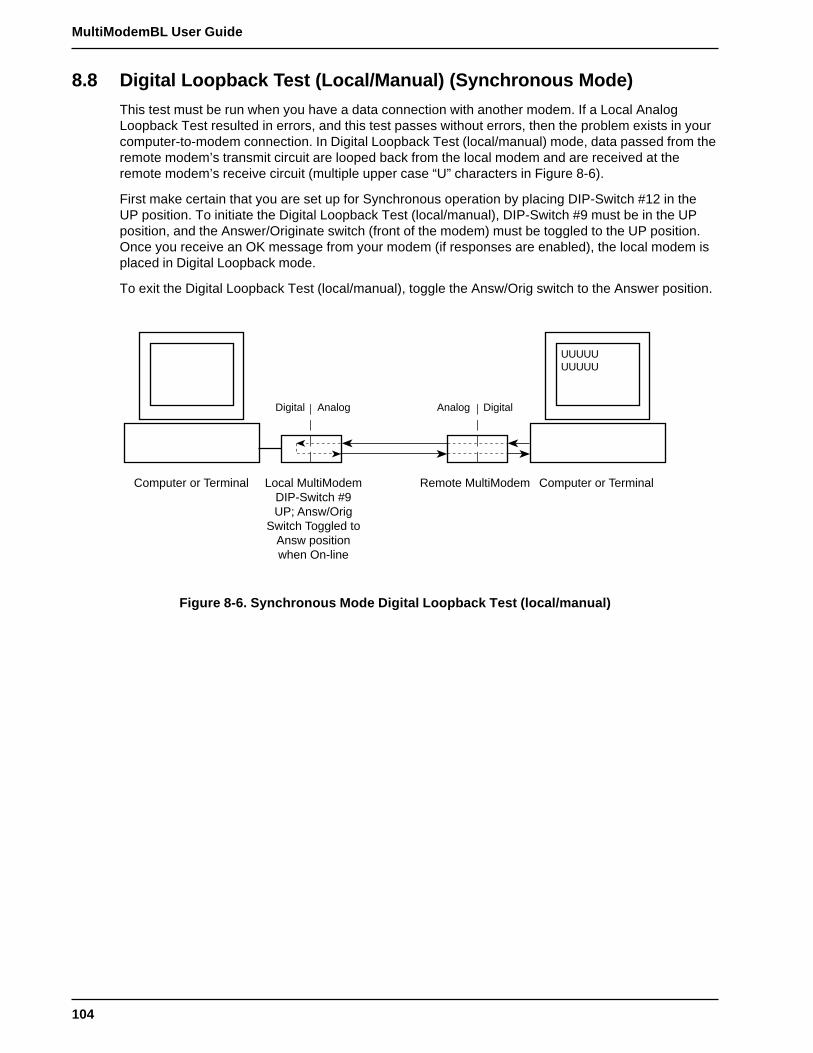
104
MultiModemBL User Guide
8.8 Digital Loopback Test (Local/Manual) (Synchronous Mode)
This test must be run when you have a data connection with another modem. If a Local AnalogLoopback Test resulted in errors, and this test passes without errors, then the problem exists in yourcomputer-to-modem connection. In Digital Loopback Test (local/manual) mode, data passed from theremote modem’s transmit circuit are looped back from the local modem and are received at theremote modem’s receive circuit (multiple upper case “U” characters in Figure 8-6).
First make certain that you are set up for Synchronous operation by placing DIP-Switch #12 in theUP position. To initiate the Digital Loopback Test (local/manual), DIP-Switch #9 must be in the UPposition, and the Answer/Originate switch (front of the modem) must be toggled to the UP position.Once you receive an OK message from your modem (if responses are enabled), the local modem isplaced in Digital Loopback mode.
To exit the Digital Loopback Test (local/manual), toggle the Answ/Orig switch to the Answer position.
UUUUUUUUUU
Computer or Terminal Local MultiModemDIP-Switch #9UP; Answ/Orig
Switch Toggled toAnsw positionwhen On-line
Remote MultiModem Computer or Terminal
Digital Analog DigitalAnalog
Figure 8-6. Synchronous Mode Digital Loopback Test (local/manual)
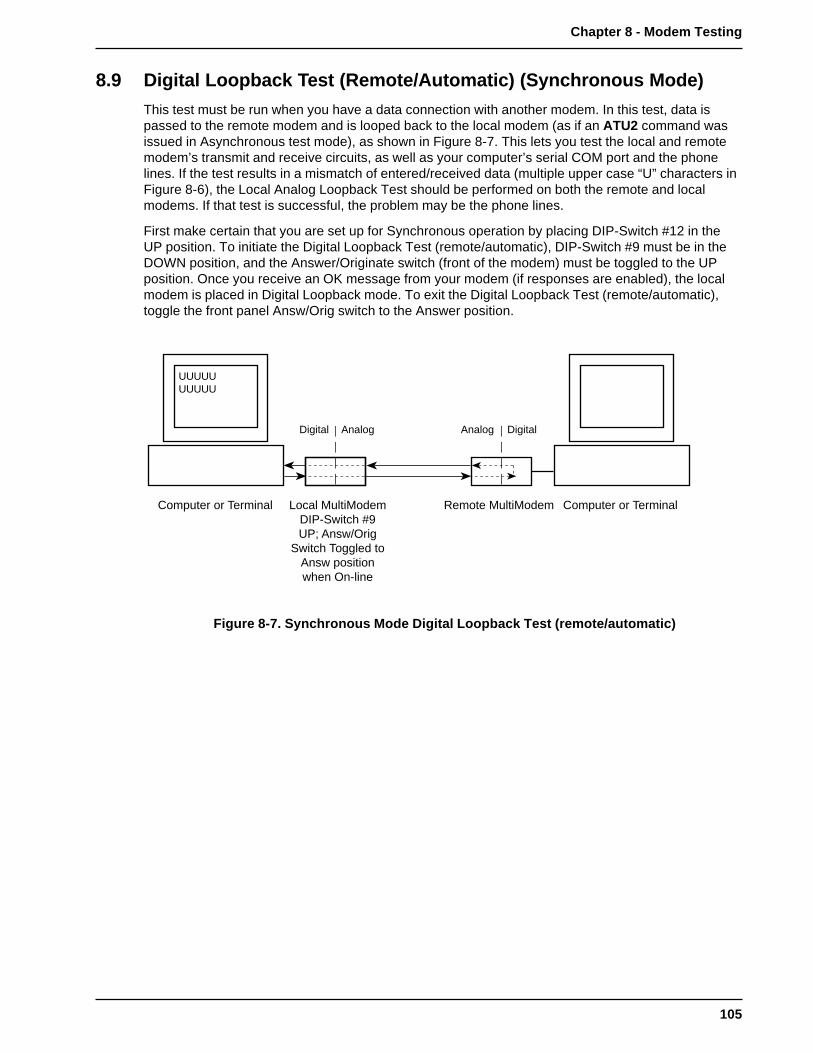
105
Chapter 8 - Modem Testing
8.9 Digital Loopback Test (Remote/Automatic) (Synchronous Mode)
This test must be run when you have a data connection with another modem. In this test, data ispassed to the remote modem and is looped back to the local modem (as if an ATU2 command wasissued in Asynchronous test mode), as shown in Figure 8-7. This lets you test the local and remotemodem’s transmit and receive circuits, as well as your computer’s serial COM port and the phonelines. If the test results in a mismatch of entered/received data (multiple upper case “U” characters inFigure 8-6), the Local Analog Loopback Test should be performed on both the remote and localmodems. If that test is successful, the problem may be the phone lines.
First make certain that you are set up for Synchronous operation by placing DIP-Switch #12 in theUP position. To initiate the Digital Loopback Test (remote/automatic), DIP-Switch #9 must be in theDOWN position, and the Answer/Originate switch (front of the modem) must be toggled to the UPposition. Once you receive an OK message from your modem (if responses are enabled), the localmodem is placed in Digital Loopback mode. To exit the Digital Loopback Test (remote/automatic),toggle the front panel Answ/Orig switch to the Answer position.
Computer or Terminal Local MultiModemDIP-Switch #9UP; Answ/Orig
Switch Toggled toAnsw positionwhen On-line
Remote MultiModem Computer or Terminal
Digital Analog DigitalAnalog
UUUUUUUUUU
Figure 8-7. Synchronous Mode Digital Loopback Test (remote/automatic)

106
MultiModemBL User Guide
Chapter 9 - DIP-Switch Settings

108
MultiModemBL User Guide
9.1 Introduction
There are several DIP-Switch options on the modem’s printed circuit (PC) board. The DIP-Switchesare accessible through a cut-out on the side of the modem. This chapter explains the modem’sprinted-circuit board options. Sixteen DIP-Switch settings and the modem's speaker volume controlare explained in detail, including all default settings.
0)�'� <�%;
$������ <�%;
��������'�<�%;
�����" !�*�''�%���
0�=�� <�%;
0�=�� �=��%)
�3$2'��%�����
��
�� � �� ��
��
� � � � � � � � �� �� ��
����������' $20��=��%)��
Figure 9-1. PC Board (BL models)
Note: There is no Phone connector on BLK models

109
Chapter 9 - DIP-Switch Settings
9.2 DIP-Switch Option Settings
Switch #1Forced DTR -- "DTR"(Asynchronous/Synchronous Mode/Leased Line/Dial-Up)
The modem must have a high DTR signal in order to operate. DTR is provided to the modem by theterminal or computer to which it is attached, through pin 20 of the RS-232C/V.24 interface. If yourterminal or computer is not providing DTR to the modem, you can force the DTR signal high with DIP-Switch #1.
DTR function normally = Switch #1 UPDTR forced On = Switch #1 DOWNFactory Default Setting = UP
Switch #2Flow Control - &E4/&E5(Asynchronous Mode/Leased Line/Dial-Up)
With Hardware Flow Control, the modem uses its RS-232C/V.24 interface to control the flow of datafrom the computer or terminal to which it is attached. The CTS signal on Pin 5 of the RS-232C/V.24is brought low to stop the flow of data, and is brought high to restart it. Place DIP-Switch #2 in the UPposition to enable Hardware Flow Control (&E4). Xon/Xoff Flow Control (&E5) is another flow controlmethod. Xon/Xoff characters in the data dictate the start and stop of data flow from the computer orterminal. Place DIP-Switch #2 in the DOWN position to select Xon/Xoff Flow Control.
Hardware Flow Control (&E4) = Switch #2 UPXon/Xoff Flow Control (&E5) = Switch #2 DOWNFactory Default Setting = UP
Switch #2SDLC/BSC Option(Synchronous Mode/Leased Line/Dial-Up)
Synchronous Data Link Control (SDLC) and Binary Synchronous Control (BSC) are two errorcorrection protocols used in the IBM Mainframe environment. Place DIP-Switch #2 in the UP positionto enable SDLC mode, and place DIP-Switch #2 in the DOWN position to enable BSC mode.
SDLC Mode = Switch #2 UPBSC Mode = Switch #2 DOWNFactory Default Setting = UP
Switch #3Enable/Suppress Responses -- "Q"(Asynchronous Mode/Dial-Up)
In some Asynchronous mode applications, you may want to suppress all responses from the modem.Place DIP-Switch #3 in the DOWN position to enable Result Code responses (Q0). Place DIP-Switch#3 in the UP position, and answer mode is handled without responses and echo turned off (Q2), butoriginate is still intelligent.
Enable Responses: Originate/Answer (Q0) = Switch #3 DOWNSuppress Responses: Answer (Q2) = Switch #3 UPFactory Default Setting = DOWN
110
MultiModemBL User Guide
*Switch #3dB Transmission Levels(Asynchronous/Synchronous Mode/Leased Line)
2834 Series:
DIP-Switch #3 adjusts dB transmission levels required by some phone carriers. Place DIP-Switch #3in the DOWN position to enable -9 dB transmission. Place DIP-Switch #3 in the UP position to enable-15 dB transmission.
-9dB Transmission = Switch #3 DOWN-15dB Transmission = Switch #3 UPFactory Default Setting = DOWN
1932 and 1432 Series:
DIP-Switch #3 adjusts dB transmission levels required by some phone carriers. Place DIP-Switch #3in the DOWN position to enable 0 dB transmission. Place DIP-Switch #3 in the UP position to enable-10 dB transmission.
0dB Transmission = Switch #3 DOWN-10dB Transmission = Switch #3 UPFactory Default Setting = DOWN
*This Switch is not applicable to BLK models.
Switch #4AS/400 Mode(Synchronous Mode/Leased Line/Dial-UP)
The modem can function in the IBM AS/400 environment (appearing like an IBM5853 modem). First,DIP-Switch #7 must be placed in the UP position. This establishes an RTS/CTS condition (statetypical for an IBM5853 modem in half-duplex mode). Next, place DIP-Switch #4 in the DOWNposition. This "spoofs" the modem into operating like an IBM5853 modem in AS/400 applications.DIP-Switch #4 in the UP position disables this function. Note that the modem must be in Commandmode to allow AS/400 mode (DIP-Switch #8 DOWN); and in Synchronous mode (DIP-Switch #12UP).
AS/400 Mode Enabled = Switch #4 DOWNAS/400 Mode Disabled = Switch #4 UPFactory Default Setting = UP
Switch #4Unix UUCP Spoofing(Asynchronous Mode/Leased Line/Dial-Up)
The modem can be configured for use with Unix equipment which employs ACK flow control tomonitor data integrity. The modem can do "UUCP spoofing", where the modem is able to generateACKs at the DTE interface. Data then is transmitted more time-efficiently, because the delay ofwaiting for data to be received then waiting for the ACK to be returned at the remote end, iseliminated. Placing DIP-Switch #4 in the DOWN position enables UUCP spoofing.
UUCP Spoofing Enabled = Switch #4 DOWNUUCP Spoofing Disabled = Switch #4 UPFactory Default Setting = UP
111
Chapter 9 - DIP-Switch Settings
Switch #5Enable/Disable Auto-Answer - "Ans"(Asynchronous Mode/Synchronous Mode/Dial-Up)
In some originate-only applications, you may wish to disable the modem’s automatic answeringcapabilities. This may be true if you have a telephone set attached to a modem and wish to receivevoice calls that you yourself would answer instead of the modem. Place DIP-Switch #5 in the UPposition to enable Auto-Answer. Place DIP-Switch #5 in the DOWN position to disable Auto-Answer.
Auto-Answer Enabled = Switch #5 UPAuto-Answer Disabled = Switch #5 DOWN(Factory Default Setting = UP)
Switch #5Originate/Answer Mode(Asynchronous/Synchronous Mode/Leased Line)
The modem functions in either Originate mode or Answer mode. Place DIP-Switch #5 in the DOWNposition to enable Originate mode. Place DIP-Switch #5 in the UP position to enable Answer mode.
Originate Mode Enabled = Switch #5 DOWNAnswer Mode Enabled = Switch #5 UP(Factory Default Setting = UP)
Switch #6Maximum Throughput Setting(Asynchronous Mode/Leased Line/Dial-Up)
Some applications require you to dial into services with maximum throughput on, and otherapplications where maximum throughput must be off (i.e., service not supporting error correction, orthe V.42 handshake interferes with logon sequence). DIP-Switch #6 is used for switching betweenthese two modes. This DIP-Switch controls three important parameters (error correction, speedconversion and serial port speed), which in effect enables or disables maximum throughput.
Maximum Throughput Enabled = Switch #6 UPMaximum Throughput Disabled = Switch #6 DOWNFactory Default Setting = UP
Switch #6Slave Clocking(Synchronous Mode/Leased Line/Dial-Up)
In Synchronous mode, DIP-Switch #6 controls the option of having timing controlled by the receiveclock. The originate modem, in effect, adjusts to the answer (remote) modem. Place DIP-Switch #6 inthe DOWN position to enable Slave Clocking. Place DIP-Switch #6 in the UP position to disableSlave Clocking.
Slave Clocking Enabled = Switch #6 DOWNSlave Clocking Disabled = Switch #6 UPFactory Default Setting = UP

112
MultiModemBL User Guide
Switch #7Request To Send Forced - "RTS"(Asynchronous/Synchronous Mode/Leased Line/Dial-Up)
If your computer or terminal uses RTS-CTS protocol (typically used in some synchronousapplications, but also if using hardware pacing for V.42 error correction or speed conversion), youmay want to set RTS to function independently of CTS (DIP-Switch #7 UP). For most applications,especially asynchronous, this switch should be set so that RTS is forced On (DIP-Switch #7 DOWN)
RTS functions Normally = Switch #7 UPRTS forced On = Switch #7 DOWNFactory Default Setting = DOWN
Switch #8Enable/Disable Command Mode -- "Com"(Asynchronous/Synchronous Mode/Leased/Dial-Up)
In some applications you may want to disable the modem's Command mode so that the modem doesnot recognize or react to AT or V.25bis commands. This may be true in strictly auto-answerapplications where no call origination is required. Place DIP-Switch #8 in the DOWN position toenable Command mode. Place DIP-Switch #8 in the UP position to disable Command mode. Thefactory default setting is Command mode enabled.
Disable Command Mode = Switch #8 UPEnable Command Mode = Switch #8 DOWNFactory Default Setting = DOWN
Switch #9Digital Loopback Test(Asynchronous/Synchronous Mode/Leased Line/Dial-Up)
When in Synchronous mode, this switch controls both Local Digital Loop and Remote Digital Looptests while on-line. When the Voice/Data switch is toggled to the Answer mode position (UP) andDIP-Switch #9 is in the UP position, the modem performs the Local Digital Loopback test. When DIP-Switch #9 is DOWN and the Voice/Data switch is toggled to Answer mode position (UP), the modemperforms the Remote Digital Loopback test.
Local Digital Loopback Test = Switch #9 UPRemote Digital Loopback Test = Switch #9 DOWNFactory Default Setting = DOWN
Switch #10Leased Line/Dial-Up Operation -- "DDD"(Asynchronous/Synchronous Mode/Leased Line/Dial-Up)
The modem operates in either leased-line or dial-up modes. This switch controls leased-line/dial-upoperation. Place DIP-Switch #10 in the UP position for Dial-Up operation. Place DIP-Switch #10 inthe DOWN position for Leased-Line operation
Dial-Up Operation = Switch #10 UPLeased Line Operation = Switch #10 DOWNFactory Default Setting = UP
113
Chapter 9 - DIP-Switch Settings
Switch #11"AT" Responses/Multi-Tech Responses(Asynchronous Mode/Leased line/Dial-Up)
In Asynchronous mode, you can set the modem to respond with Result Codes according to the"Multi-Tech" command response set (Switch #11 in the DOWN position), or to "AT" commandresponse set (Switch #11 in the UP position). The &Q command performs the same function(choosing AT or Multi-Tech Result Codes), and is explained further in Section 5.3 of this manual.
"AT" Responses (&Q1) = Switch #11 UP"Multi-Tech" Responses (&Q0 = Switch #11 DOWNFactory Default Setting = DOWN
Switch #11Internal/External Clocking(Synchronous Mode/Leased Line/Dial-Up)
In Synchronous mode, the transmit clock can be supplied by the DTE on pin 24 of the RS-232C/V.24interface by placing DIP-Switch #11 UP. Place DIP-Switch #11 in the DOWN position to enable DCEto control clocking (internal clock via pins 15 and 17 of the RS-232/V.24 interface).
External Clock (pin 24) = Switch #11 UPInternal Clock (pins 15/17) = Switch #11 DOWNFactory Default Setting = DOWN
Switch #12Asynchronous/Synchronous Operation -- "Sync"(Asynchronous/Synchronous Mode/Leased Line/Dial-Up)
The modem can operate in either Asynchronous mode or Synchronous mode. In Synchronous mode,start and stop bits are eliminated. The modem's internal clock circuits on the RS-232C/V.24 pins 15and 17 are activated. The modem's Command mode is not accessible in Synchronous mode. Thisswitch is a means to alternate and to access either mode. In Synchronous mode, you may want toset the RTS forcing and CTS forcing DIP-Switches so that both of signals act normally (not forcedon).
Synchronous Operation = Switch #12 UPAsynchronous Operation = Switch #12 DOWNFactory Default Setting = DOWN
Switches #13 and #14Speed Switches(Synchronous Mode/Leased Line)
DIP-Switches #13 and #14 are used to set the modem’s data transmission rate. Switches #13 and#14 are used in combination, typically in leased-line and call origination applications.
Note: The modem baud rate command ($MBn) overrides the setting of these speed selectionswitches (DIP switches #13 and #14).
2834 Series:
28800 bps Operation = Switch #13 UP and Switch #14 UP19200 bps Operation = Switch #13 DN and Switch #14 UP14400 bps Operation = Switch #13 UP and Switch #14 DN9600 bps Operation = Switch #13 DN and Switch #14 DN
Factory Default Setting = Switch #13 UP and Switch #14 UP

114
MultiModemBL User Guide
1932 Series:
19200 bps Operation = Switch #13 UP and Switch #14 UP14400 bps Operation = Switch #13 DN and Switch #14 UP9600 bps Operation = Switch #13 UP and Switch #14 DN2400 bps Operation = Switch #13 DN and Switch #14 DN
Factory Default Setting = Switch #13 UP and Switch #14 UP
1432 Series:
14400 bps Operation = Switch #13 UP and Switch #14 UP9600 bps Operation = Switch #13 DN and Switch #14 UP4800 bps Operation = Switch #13 UP and Switch #14 DN2400 bps Operation = Switch #13 DN and Switch #14 DN
Factory Default Setting = Switch #13 UP and Switch #14 UP
Switch #15Carrier Detect/DSR Forcing -- "DSR"(Asynchronous/Synchronous Mode/Dial-Up/Leased Line)
Some terminals react in unusual ways to the toggling of the Carrier Detect (CD - RS-232C/V.24 pin6) signals. The most common symptom is that the modem does not respond to commands, or doesnot echo characters. In these cases, it is advisable to force these two signals On in order for theterminal to communicate properly with the modem in Command mode. This is done by setting DIP-Switch #15 DOWN. With DIP-Switch #15 in the UP position, both CD and DSR will be either on or off,depending on the On-Line status.
CD and DSR normal = Switch #15 UPCD and DSR forced On = Switch #15 DOWNFactory Default Setting = UP
Switch #162 Wire/4 Wire Operation(Asynchronous/Synchronous Mode)
The modem works over either 2-wire or 4-wire leased lines. To select 4-wire operation, place Switch#16 DOWN (Default); and to select 2-wire operation, place Switch #16 UP.
2-Wire Leased Line = Switch #16 UP4-Wire Leased Line = Switch #16 DOWNFactory Default Setting = DOWN
9.3 Speaker Volume Control
You can adjust the volume of the modem’s phone-line monitor speaker with a volume control knob,located on the back of the modem next to the RS-232C connector (see Figure 9-1 for location). Turnthe knob clockwise to increase the modem's volume and counterclockwise to decrease speakervolume. See Speaker Control Command (M) in Section 5.4.6.

115
Chapter 9 - DIP-Switch Settings
9.4 Recording Option Configurations
This section lets you record any changes you may have made to the DIP-Switch settings. Circle theappropriate setting and record the effect for future reference.
DIP-Switches
Switch Function Position Effect
#1 Force DTR/DTR from Interface* UP*DOWN
#2 Flow Control &E4*/&E5 UP*(Async/Dial-Up/Leased Line) DOWN
#2 SDLC*/BSC (Sync) UP*DOWN
#3 Result Codes Enable*/Disable UP(Async/Dial-up) DOWN*
#3 DbM Transmit (-9db/0dB)*/(-15db/-10dB) UP(Async/Sync/Lease-Line) DOWN*
#4 UUCP Enable/Disable* UP*(Async/Dial-Up/Leased Line) DOWN
#4 AS/400 Enable/Disable* UP*(Sync/Dial-Up/Leased line) DOWN
#5 Auto-Answer Enable*/Disable UP*(Async/Sync/Dial-Up) DOWN
#5 Answer*/Originate DOWN(Async/Sync/Leased Line) UP*
#6 Max-Thru Enable*/Disable UP*(Async/Dial-Up/Leased) DOWN
#6 Slave Clock Enable/Disable* UP*(Sync/Dial-Up/Leased) DOWN
#7 RTS/Normal/Forced* UP(Sync/Async/Dial/Leased) DOWN*
#8 Command Mode Enabled* UP(Sync/Async/Dial/Leased) DOWN*
#9 Local/Remote* LoopBack UP(Async/Sync/Dial/Leased) DOWN*
#10 Dial-Up*/Leased-Line UP*DOWN
#11 "AT"/"Multi-Tech" Result Codes* UP(Asynchronous) DOWN*
#11 Internal*/External Clocking UP(Synchronous) DOWN*
#12 Sync/Async Mode* UPDOWN*
* Factory Default Setting
116
MultiModemBL User Guide
DIP Switches #13-14
Note: The modem baud rate command ($MBn) overrides the setting of these speed selectionswitches (DIP switches #13 and #14).
2834 Series:
SWITCH CONDITION EFFECT
#13/#14 UP/UP* 28.8 K bps Operation
#13/#14 DOWN/UP 19.2 K bps Operation
#13/#14 UP/DOWN 14.4 K bps Operation
#13/#14 DOWN/DOWN 9600 bps Operation
1932 Series:
SWITCH CONDITION EFFECT
#13/#14 UP/UP* 19.2 K bps Operation
#13/#14 DOWN/UP 14.4 K bps Operation
#13/#14 UP/DOWN 9600 bps Operation
#13/#14 DOWN/DOWN 2400 bps Operation
1432 Series:
SWITCH CONDITION EFFECT
#13/#14 UP/UP* 14.4 K bps Operation
#13/#14 DOWN/UP 9600 bps Operation
#13/#14 UP/DOWN 4800 bps Operation
#13/#14 DOWN/DOWN 2400 bps Operation
DIP Switches #15-16
#15 UP* CD/DSR from Interface
#15 DOWN CD/DSR Forced On
#16 UP 2-Wire Leased Line
#16 DOWN* 4-Wire Leased Line
*Standard Factory Default Setting

Chapter 10 - Warranty, Service and Tech Support

118
MultiModemBL User Guide
10.1 Introduction
This chapter starts out with statements about your modem's 5-year warranty. The next section, TechSupport, should be read carefully if you have questions or problems with your modem. It includes thetechnical support telephone numbers, space for recording your modem information, and anexplanation of how to send in your modem should you require service. The final four sections explainhow to use our Bulletin Board Service (BBS), upgrading the modem via Flash PROM, a brief sectionon the CompuServe/Internet forums and information on Multi-Tech's Fax-Back Service.
10.2 Limited Warranty
Multi-Tech Systems, Inc. (“MTS”) warrants that its products will be free from defects in material orworkmanship for a period of five years from the date of purchase, or if proof of purchase is notprovided, five years from date of shipment. MTS MAKES NO OTHER WARRANTY, EXPRESSEDOR IMPLIED, AND ALL IMPLIED WARRANTIES OF MERCHANTABILITY AND FITNESS FOR APARTICULAR PURPOSE ARE HEREBY DISCLAIMED. This warranty does not apply to anyproducts which have been damaged by lightning storms, water, or power surges or which have beenneglected, altered, abused, used for a purpose other than the one for which they were manufactured,repaired by the customer or any party without MTS’s written authorization, or used in any mannerinconsistent with MTS’s instructions.
MTS’s entire obligation under this warranty shall be limited (at MTS’s option) to repair or replacementof any products which prove to be defective within the warranty period, or, at MTS’s option, issuanceof a refund of the purchase price. Defective products must be returned by Customer to MTS’s factorytransportation prepaid.
MTS WILL NOT BE LIABLE FOR CONSEQUENTIAL DAMAGES AND UNDER NOCIRCUMSTANCES WILL ITS LIABILITY EXCEED THE PURCHASE PRICE FOR DEFECTIVEPRODUCTS.
10.2.1 On-line Warranty Registration
To register your MultiModem on-line, click on the following link:
http://www.multitech.com/register
119
Chapter 10 - Warranty, Service and Tech Support
10.3 Tech Support
Multi-Tech has an excellent staff of technical support personnel available to help you get the most outof your Multi-Tech product. If you have any questions about the operation of this unit, call 1-800-972-2439. Please fill out the modem information (below), and have it available when you call. If yourmodem requires service, the tech support specialist will guide you on how to send in your modem(see Section 10.3.2).
10.3.1 Recording Modem Information
Please fill in the following information on your Multi-Tech modem. This will help tech support inanswering your questions.
Modem Model No.:Modem Serial No.:Modem Firmware Version:COM Port #:FAX Software Type and Version:DataComm Software Type and Version:
The modem model and serial numbers are silkscreened on the bottom of your modem. The softwareversions are printed on the diskette labels. Type ATI1 to display the modem firmware version.
Please note the status of your modem before calling tech support. This status can include LEDindicators, screen messages, diagnostic test results, problems with a specific application, etc. Usethe space below to note modem status:
10.4 Service
If your tech support specialist decides that service is required, modems may be sent (freight prepaid)to our factory. Return shipping charges will be paid by Multi-Tech Systems (within North America).
Include the following with your modem:
• a description of the problem.
• return billing and return shipping addresses.
• contact name and phone number.
• check or purchase order number for payment if the modem is out of warranty. (The standardrepair charge for this modem is $95. This price is valid at the time of this publication but couldchange in the future. Check with your technical support specialist.)
• if possible, note the name of the technical support specialist with whom you spoke.
If you need to inquire about the status of the returned product, be prepared to provide the serialnumber of the product sent (see Section 10.3.1).
Send modems to this address:
MULTI-TECH SYSTEMS, INC.2205 WOODALE DRIVEMOUNDS VIEW, MINNESOTA 55112ATTN: SERVICE OR REPAIRS

120
MultiModemBL User Guide
10.5 The Multi-Tech BBS
For customers who do not have Internet access, Multi-Tech maintains a bulletin board system (BBS)that mirrors its FTP site. Information available from the BBS includes new product information,product upgrade files, and problem-solving tips. The phone number for the Multi-Tech BBS is (800)392-2432 (USA and Canada) or (612) 785-3702 (international and local).
The BBS can be accessed by any asynchronous modem operating at 1200 bps to 33,600 bps at asetting of 8 bits, no parity, and 1 stop bit (8-N-1).
To log on to the Multi-Tech BBS
1. Set your communications program to 8-N-1.
2. Dial our BBS at (800) 392-2432 (USA and Canada) or (612) 785-3702 (international and local).
3. At the prompts, type your first name, last name, and password; then press ENTER. If you are afirst time caller, the BBS asks if your name is spelled correctly. If you answer yes, aquestionnaire appears. You must complete the questionnaire to use the BBS on your first call.
4. Press ENTER until the Main Menu appears. From the Main Menu you have access to two areas:the Files Menu and News. For help on menu commands, type ?.
To Download a file
If you know the file name
1. From the Main Menu, type F to access the Files Menu, then type D.
2. Enter the name of the file you wish to download from the BBS.
3. If a password is required, enter the password.
4. Answer Y or N to the automatic logoff question.
5. Select a file transfer protocol by typing the indicated letter, such as Z for Zmodem (therecommended protocol).
6. If you select Zmodem, the transfer will begin automatically. If you select another protocol, youmay have to initiate the transfer yourself. (In most datacomm programs, the PAGE DOWN keyinitiates the download.)
7. When the download is complete, press ENTER to return to the File Menu.
8. To exit the BBS, type G and press ENTER.
If you don’t know the file name
1. From the Main Menu, type F to access the Files Menu. For a list of file areas, type L, pressENTER, then type L and press ENTER again. (If you do not type the second L, you will list all ofthe files on the BBS.)
2. Mark each file area you would like to examine by typing its list number and pressing ENTER.
3. Enter L to list all the files in the selected file areas. Enter C to go forward in the file list and P togo back.
4. To mark one or more files for download, type M, press ENTER, type the list numbers of the files,and press ENTER again.
5. Enter D. You will see a list of the files you have marked. Enter E if you would like to edit the list;otherwise enter D again to start the download process.
6. Select a file transfer protocol by typing the indicated letter, such as Z for Zmodem (therecommended protocol).
7. If you select Zmodem, the file will transfer automatically. If you select another protocol, you mayhave to initiate the transfer yourself. (In most data communications programs, the PAGE DOWNkey initiates the download.)
8. When the download is complete, press ENTER to return to the File Menu.
9. To exit the BBS, type G and press ENTER.

121
Chapter 10 - Warranty, Service and Tech Support
10.5.1 Upgrading the MultiModem
The MultiModem has a Flash PROM which contains firmware code for the hardware and DSP codefor the digital signal processor chips. At various times, Multi-Tech may add enhancements and/orfixes to the firmware. The flash technology used in the MultiModem lets you load these upgrades intothe PROM or DSP chips through the modem's serial port.
10.5.2 Using FlashPro to Upgrade Modem Firmware
1. Download FLASHPRO.ZIP and a new .HEX file from the Multi-Tech BBS.
2. Unzip the FLASHPRO.ZIP file. Place this unzipped file and the .HEX file in the same directory.
3. Run FlashPro by typing FLASHPRO, a space, -M and hitting ENTER at the DOS prompt.
4. Highlight the "Configure" option in the MAIN MENU and hit ENTER. Highlight "Active Port" andselect the COM port to which you have your modem attached. Highlight "Baud Rate" and selectthe rate you want to program at. Hit ESC when finished.
5. Highlight the "Select File to Program" option in the MAIN MENU. Highlight the .HEX file. Hit ESCwhen finished.
6. Highlight "Program Firmware" option in the MAIN MENU. When you are prompted to confirm thefile to program, press "Y".
7. If you need more assistance programming FLASHPRO, then contact our tech supportdepartment.
10.6 About Multi-Tech’s Internet Presence
Multi-Tech's presence includes a Web site at:
http://www.multitech.com
and an ftp site at:
ftp://ftp.multitech.com
10.7 About the Multi-Tech Fax-Back Service
Multi-Tech's fax-back system provides 24-hour access to sales, marketing, and technical literature.Dial 612-717-5888, follow the voice prompts, and request document number 10 for a catalog ofavailable documents.
For convenience, have your fax number handy: __________________ . From the catalog ofavailable documents, you can order newsletters, white papers, press releases, etc. from the salesand marketing index (pages 1-4), or order basic modem operation and troubleshooting guides fromthe technical support and engineering index. Just enter the applicable FB Doc. # from the left columnof the catalog.

122
MultiModemBL User Guide
10.8 About Ordering Accessories
SupplyNet, Inc. can supply you with replacement transformers, cables and connectors for selectMulti-Tech products. You can place an order with SupplyNet via mail, phone, fax or the Internet at:
Mail: SupplyNet, Inc.614 Corporate WayValley Cottage, NY 10989
Phone: 800 826-0279
Fax: 914 267-2420
Email: [email protected]
Internet: http://www.thesupplynet.com
SupplyNet Online Ordering Instructions
1. Browse to http://www.thesupplynet.com. In the Browse by Manufacturer drop-down list,select Multi-Tech and click
2. To order, type in quantity, and click
3. Click to change your order
4. After you have selected all of your items click to finalize the order. The SupplyNetsite uses Verisign’s Secure Socket Layer (SSL) technology to ensure your complete shoppingsecurity.

Appendixes

124
MultiModemBL User Guide
Appendix A - Troubleshooting
Your modem was thoroughly tested at the factory before it was shipped. If you are unable to make asuccessful connection or if you experience data loss or garbled characters during your connection, itis possible that the modem is defective. However, it is more likely that the source of your problem lieselsewhere. Problems you may encounter include the following:
• None of the LEDs light when the modem is on.• The modem does not respond to commands.• The modem dials but is unable to make a connection.• The modem disconnects while on-line.• The modem cannot connect when answering.• File transfer is slower than it should be.• I am losing data.• I am getting garbage characters on the monitor.• I can’t run my fax and communications software at the same time.
If you experience problems, please check the following possibilities before calling Tech Support (seeChapter 10).
None of the LEDs Light When the Modem Is On
When you turn on the modem, the LED indicators on the front panel should flash briefly as themodem runs a self-test. If the LEDs remain off, the modem is probably not receiving power.
• Make sure the modem’s power switch is on, especially if you normally turn on the modem byturning on a power strip.
• If the power supply is plugged into a power strip, make sure the power strip is plugged in and itspower switch is on.
• Make sure the power supply module is firmly connected to the modem and to the wall outlet orpower strip.
• If the power strip is on and the modem switch is on, try moving the modem power supply toanother outlet on the power strip.
• Test that the outlet is live by plugging a lamp into it.
• The modem or power supply may be defective. If you have another Multi-Tech modem, tryswapping modems. If the problem goes away, the first modem or power supply may be defective.Call Tech Support for assistance.
CAUTION: Do not under any circumstances replace the power supply module with one designed foranother product, as it may damage the modem and void your warranty.
The Modem Does Not Respond to Commands
• Make sure the modem is plugged in and turned on. (See “None of the LEDs Light When theModem Is On.”)
• Make sure you are issuing the modem commands from the data communications software, eithermanually in terminal mode or automatically by configuring the software. (You cannot sendcommands to the modem from the DOS prompt.)
• Make sure you are in terminal mode in your data communications program, then type AT andpress ENTER. If you get an OK response, your connections are good and the problem likely is inyour phone book entry or session settings.
• Try resetting your modem by turning it off and on. Make sure there is a reset command (&F) inyour initialization string, or your modem may not initialize correctly.

125
Appendix A - Troubleshooting
• If you don’t get an OK, the problem may still be in the communications software. Make sure youhave done whatever is necessary in your software to make a port connection. Not allcommunications programs connect to the COM port automatically. Some connect when thesoftware loads and remain connected until the program terminates. Others can disconnectwithout exiting the program (make sure the Connect icon looks plugged in). If the terminal reportsthat it cannot make a connection, yet the modem’s TR indicator is on, click on the Window menuto see if more than one terminal is open. The modem’s TR indicator shows that the software hasmade a connection with the modem through the COM port.
• Your communications software settings may not match the physical port the modem is connectedto. The serial cable may be plugged into the wrong connector—check your computerdocumentation to make sure. Or you may have selected a COM port in your software other thanthe one the modem is physically connected to—compare the settings in your software to thephysical connection.
• If the modem is on, the cable is plugged into the correct port, the communications software isconfigured correctly, and you still don’t get an OK, the fault may be in the serial cable. Make sureit is firmly connected at both ends.
• Is this the first time you have used the cable? If so, it may not be correct. Check the cabledescription on the packaging to make sure the cable is the right one for your computer.
• Peripheral expansion cards, such as bus mouse and sound cards, may include a serial port pre-configured as COM1 or COM2. The extra serial port, or the card itself, may use the same COMport, memory address, or interrupt request (IRQ) as your communications port. Be sure todisable any unused ports.
To look for address or IRQ conflicts if you use Windows 3.1x, select File, Run in ProgramManager, type MSD, and press ENTER. Then select Mouse, COM Ports, and IRQ Status andnote the addresses and IRQs that are in use. If you find an IRQ conflict, note which IRQs are notbeing used, then change one of the conflicting devices to use one of the unused IRQs. If you findan address conflict, change the address of one of the conflicting devices.
To change a port address or IRQ in Windows 3.1x, double-click the Control Panel icon, then thePorts icon. Click on the port you want to change, click Settings, click Advanced, and select thenew port address and/or interrupt. If you wish to use COM3 or COM4, note that COM3 shares anIRQ with COM1, as does COM4 with COM2, so you should change their IRQs to unused ones, ifpossible.
If you use Windows 95, right-click on My Computer, select Properties from the menu, click on theDevice Manager tab, double-click on Ports, then double-click on the Communications Port yourmodem is connected to. In the port’s Properties sheet, click on the Resources tab to see theport’s Input/Output range and Interrupt Request. If another device is using the same addressrange or IRQ, it will appear in the Conflicting Device List. Uncheck Use Automatic Settings tochange the port’s settings so they do not conflict with the other device, or select the port theconflicting device is on and change it instead. If you need to open your computer to changeswitches or jumpers on the conflicting device; refer to the device’s documentation.
• The serial port may be defective. If you have another serial port, install the modem on it, changethe COM port setting in your software, and try again.
• The modem may be defective. If you have another Multi-Tech modem, try swapping modems. Ifthe problem goes away, the first modem is possibly defective. Call Tech Support for assistance(see Chapter 10).
126
MultiModemBL User Guide
The Modem Dials But Cannot Make a Connection
There can be several reasons the modem fails to make a connection. Possibilities include
• lack of a physical connection to the telephone line.• a wrong dial tone.• a busy signal.• a wrong number.• no modem at the other end.• a faulty modem, computer, or software at the other end.• incompatibility between modems.
You can narrow the list of possibilities by using extended result codes. To enable them, enterATV1X4 and press ENTER while in terminal mode, or include V1X4 in the modem’s initializationstring. When you dial again, the modem will report the call’s progress.
• If the modem reports NO DIALTONE, check that the modem’s telephone line cable is connectedto both the modem’s LINE jack (not the PHONE jack) and the telephone wall jack. If the cablelooks secure, try replacing it. If that doesn’t work, the problem may be in your building’stelephone installation. To test the building installation, plug a telephone into your modem’stelephone wall jack and listen for a dial tone. If you hear a dial tone, your modem may beinstalled behind a company phone system (PBX) with an internal dial tone that sounds differentfrom the normal dial tone. In that case, the modem may not recognize the dial tone and may treatit as an error. Check your PBX manual to see if you can change the internal dial tone; if youcan’t, change your modem’s initialization string to replace X4 with X3, which will cause themodem to ignore dial tones.
• If the modem reports BUSY, the other number may be busy, in which case you should try againlater, or it may indicate that you have failed to add a 9, prefix to the phone number if you mustdial 9 for an outside line.
If you must dial 9 to get an outside line, the easiest way to dial it automatically is to include it inthe modem’s dial prefix, e.g., ATDT9,. Note the comma, which inserts a pause before thenumber is dialed. By inserting 9, into the dial prefix, you do not have to include it in each directoryentry in the terminal.
To change the dial prefix in Windows Terminal, select Settings, Modem Commands. To change itin Windows 95 HyperTerminal, select Call, Connect from the menu bar, click Dialing Properties,and type 9 in the local and long distance boxes in How I Dial from This Location.
• If the modem reports NO ANSWER, the other system has failed to go off-hook, or you mighthave dialed a wrong number. Check the number.
• If the modem reports NO CARRIER, the phone was answered at the other end, but noconnection was made. You might have dialed a wrong number, and a person answered insteadof a computer, or you might have dialed the correct number but the other computer or softwarewas turned off or faulty. Check the number and try again, or try calling another system to makesure your modem is working. Also, try calling the number on your telephone. If you hear harshsounds, then another modem is answering the call, and the modems may be having problemsnegotiating because of modem incompatibilities or line noise. Try connecting at a lower speed.

127
Appendix A - Troubleshooting
The Modem Disconnects While On-line
• If you have call waiting on the same phone line as your modem, it may interrupt your connectionwhen someone tries to call you. If you have call waiting, disable it before each call. In mosttelephone areas, you can disable call waiting by preceding the telephone number with *70 (checkwith your local telephone company).
You can automatically disable call waiting by including the disabling code in the modem’s dialprefix (e.g., ATDT*70,—note the comma, which inserts a pause before the number is dialed). Tochange the dial prefix in Windows Terminal, select Settings, Modem Commands. To change it inWindows 95 HyperTerminal, select Call, Connect from the menu bar, click Dialing Properties,check this location has Call Waiting, and select the correct code for your phone service.
• If you have extension phones on the same line as your modem, you or someone else caninterrupt the connection by picking up another phone. If this is a frequent problem, disconnect theextension phones before using the modem, or install another phone line especially for themodem.
• Check for loose connections between the modem and the computer, the telephone jack, and ACpower.
• You may have had a poor connection because of line conditions or the problem may haveoriginated on the other end of the line. Try again.
• If you were on-line with a BBS, it may have hung up on you because of lack of activity on yourpart or because you exceeded your time limit for the day. Try again.
The Modem Cannot Connect When Answering
• Auto-answer may be disabled. Turn on auto-answer in your datacomm program or send thecommand ATS0=1 to your modem in terminal mode.
File Transfer Is Slower Than It Should Be
• You may have an older UART. For best throughput, install a 16550AFN UART or a Multi-Tech ISIserial port card. See the “Quick Start” chapter for information on how to identify your UART.
• If you are running under Windows 3.1 and have a 16550AFN UART, you must replace theWindows serial driver, COMM.DRV, to take full advantage of the UART’s speed.
• If you are using a slow transfer protocol, such as Xmodem or Kermit, try Zmodem or Ymodem/Ginstead.
• Is your line noisy? If there is static on your line, the modem has to re-send many blocks of data toinsure accuracy. You must have a clean line for maximum speed.
• Are you downloading a compressed file with MNP 5 hardware compression enabled? Sincehardware data compression cannot compress a file already compressed by an archivingprogram, the transfer can be marginally slower with data compression enabled than with itdisabled.
• Try entering the L8 (List Online Diagnostics) command in on-line mode, making a screen print ofthe diagnostics listing, and checking for parameters that may be unacceptable (number ofretrains, round trip delay, etc.).

128
MultiModemBL User Guide
I Am Losing Data
• If you are using data compression and a high speed serial port, set the serial port baud rate tofour times the data rate.
• Your UART may not be reliable at serial port speeds over 9600 bps or 19,200 bps. Turn off datacompression, reset your serial port speed to a lower rate, or replace your serial port with a fasterone.
• Make sure the flow control method you selected in software matches the method selected in themodem. If you have a Macintosh, you may have the wrong cable for hardware flow control.
• If you are running under Windows 3.1 and have a 16550AFN UART, you may need to turn on the16550’s data buffers and/or replace the Windows serial driver, COMM.DRV.
• Try entering the L8 (List Online Diagnostics) command in on-line mode, making a screen print ofthe diagnostics listing, and checking for parameters that may be unacceptable (number ofretrains, round trip delay, etc.).
I Am Getting Garbage Characters on the Monitor
• Your computer and the remote computer may be set to different word lengths, stop bits, orparities. If you have connected at 8-N-1, try changing to 7-E-1, or vice-versa, using yourcommunications software.
• You may be experiencing line noise. Enable error correction, if it is disabled, or hang up and callagain; you may get a better connection.
• At speeds above 2400 bps, the remote modem might not use the same transmission or errorcorrection standards as your modem. Try connecting at a slower speed or disabling errorcorrection. (With no error correction, however, line noise can cause garbage characters.)
• Try entering the L8 (List Online Diagnostics) command in on-line mode, making a screen print ofthe diagnostics listing, and checking for parameters that may be unacceptable (number ofretrains, round trip delay, etc.).
My Fax and Communications Software Won’t Run at the Same Time
Communications devices can be accessed by only one application at a time. Under DOS or Windows3.1x, you can run either your fax software or your datacomm software, but not both at the same time,unless you have a special communications device management application, such as Multi-Tech’sVirtual Modem Driver. In Windows 95, you can have data and fax communication applications openat the same time, but they cannot use the same modem at the same time.

129
Appendix B - ASCII Conversion Chart
Appendix B - ASCII Character Code/Hex/Decimal Conversion Chart
CTRL CODE HEX DEC CODE HEX DEC CODE HEX DEC CODE HEX DEC@ NUL 00 0 SP 20 32 @ 40 64 60 96A SOH 01 1 ! 21 33 A 41 65 a 61 97B STX 02 2 “ 22 34 B 42 66 b 62 98C ETX 03 3 # 23 35 C 43 67 c 63 99D EOT 04 4 $ 24 36 D 44 68 d 64 100E ENQ 05 5 % 25 37 E 45 69 e 65 101F ACK 06 6 & 26 38 F 46 70 f 66 102G BEL 07 7 ‘ 27 39 G 47 71 g 67 103H BS 08 8 ( 28 40 H 48 72 h 68 104I HT 09 9 ) 29 41 I 49 73 i 69 105J LF 0A 10 * 2A 42 J 4A 74 j 6A 106K VT 0B 11 = 2B 43 K 4B 75 k 6B 107L FF 0C 12 , 2C 44 L 4C 76 l 6C 108M CR 0D 13 - 2D 45 M 4D 77 m 6D 109N SO 0E 14 . 2E 46 N 4E 78 n 6E 110O SI 0F 15 / 2F 47 O 4F 79 o 6F 111P DLE 10 16 0 30 48 P 50 80 p 70 112Q DC1 11 17 1 31 49 Q 51 81 q 71 113R DC2 12 18 2 32 50 R 52 82 r 72 114S DC3 13 19 3 33 51 S 53 83 s 73 115T DC4 14 20 4 34 52 T 54 84 t 74 116U NAK 15 21 5 35 53 U 55 85 u 75 117V SYN 16 22 6 36 54 V 56 86 v 76 118W ETB 17 23 7 37 55 W 57 87 w 77 119X CAN 18 24 8 38 56 X 58 88 x 78 120Y EM 19 25 9 39 57 Y 59 89 y 79 121Z SUB 1A 26 : 3A 58 Z 5A 90 z 7A 122[ ESC 1B 27 ; 3B 59 [ 5B 91 { 7B 123\ FS 1C 28 < 3C 60 \ 5C 92 | 7C 124] GS 1D 29 = 3D 61 ] 5D 93 } 7D 125
RS 1E 30 > 3E 62 ^ 5E 94 – 7E 126— US 1F 31 ? 3F 63 _ 5F 95 DEL 7F 127
NUL Null, or all zeros DC1 Device Control 1 SI Shift InSOH Start of Header DC2 Device Control 2 SO Shift OutSTX Start of Text DC3 Device Control 3 SYN Sync.ETX End of Text DC4 Device Control 4 LF Line FeedEOT End of Transmission CAN Cancel FF Form FeedACK Acknowledge EM End of Medium ENQ EnquiryBEL Bell or Alarm SUB Substitute ESC EscapeBS Backspace FS File Separator DLE Data Link EscapeHT Horizontal Tab GS Group Separator NAK Negative Acknowledge VT Vertical Tab RS Record Separator CR Carriage ReturnETB End Transmission Block DEL Delete
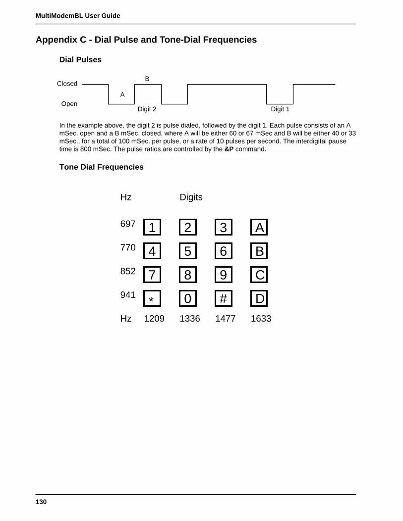
130
MultiModemBL User Guide
Appendix C - Dial Pulse and Tone-Dial Frequencies
Dial Pulses
Closed
Open
B
A
Digit 2 Digit 1
In the example above, the digit 2 is pulse dialed, followed by the digit 1. Each pulse consists of an AmSec. open and a B mSec. closed, where A will be either 60 or 67 mSec and B will be either 40 or 33mSec., for a total of 100 mSec. per pulse, or a rate of 10 pulses per second. The interdigital pausetime is 800 mSec. The pulse ratios are controlled by the &P command.
Tone Dial Frequencies
Hz Digits
697
770
852
941
Hz 1209 1336 1477 1633
1 2 3 A
4 5 6 B
7 8 9 C
0 # D*

131
Appendix D - AT Command Summary
Appendix D - Command Summary
Command Values Description
AT Attention Code that precedes most command stringsexcept A/, A: and Escape Codes.
RETURN Pressing RETURN key executes most commands.
$ This symbol placed in dialing string enables themodem to detect AT&T's "call card" tones foraccessing user's calling card to originate an on-lineconnection.
A Answer call, even if no ring present. Repeat lastcommand. (Do not precede this command with AT.Do not hit RETURN to execute.)
***A: Continuous redial (10 redials in DOC units) of lastnumber until answered. (Not used Internationally.)
$An n = 0 or 1 * $A0 discards data during auto-reliable time period.$A1 buffers data during auto-reliable time period.
#An n = 0 thru 3 2834 Series:
* #A0 selects initial handshake at:33,600 to 31,200 to28,800 to 24000 to 21,600 to 19,200 to 16,800 to14,400 to 12,000 to 9600 to 4800 to 2400 to 1200 to300 bps.#A1 selects initial handshake at 33,600 bps only.#A2 selects initial handshake at 33,600 to 31,200 to28,800 to 24000 to 21600 to 19,200 to 16,80019,200 to 14,400 to 9600 to 4800 bps.#A3 selects initial handshake at 2400 to 1200 to 300bps.
1932 Series:
* #A0 selects initial handshake at: 19,200 to 16,800 to14,400 to 12,000 to 9600 to 4800 to 2400 to 1200 to300 bps.#A1 selects initial handshake at 19,200 bps only.#A2 selects initial handshake at 19,200 to 16,800 to14,400 to 9600 to 4800 bps.#A3 selects initial handshake at 2400 to 1200 to 300bps.
1432 Series:
* #A0 selects initial handshake at: 14,400 to 12,000 to9600 to 4800 to 2400 to 1200 to 300 bps.#A1 selects initial handshake at 14,400 bps only.#A2 selects initial handshake at 14,400 to 9600 to4800 bps.#A3 selects initial handshake at 2400 to 1200 to 300bps.
* Factory Default Setting*** Not applicable in BLK models

132
MultiModemBL User Guide
Command Values Description
***Bn n = 0 or 1 * B0 selects V.21 answer tone.B1 selects Bell answer tone.
&Bn n = 0 or 1 * &B0 means normal transmit buffer size.&B1 means reduced transmit buffer size.
&BSn n = 0 or 1 &BS0 means maximum transmit block size of 64characters.
* &BS1 means maximum transmit block size of 256characters.
$BAn n = 0 or 1 * $BA0 means speed conversion is on.$BA1 means speed conversion is off.
&Cn n = 0,1,2,4 &C0 forces Carrier Detect on.* &C1 lets Carrier Detect act normally.
&C2 lets Carrier Detect drop S24 time ondisconnect.&C4 resets modem when Carrier Detect drops.
&CDn n = 0 or 1 * &CD0 execute cleardown on disconnect.&CD1 do not execute cleardown on disconnect.
Ds s = phone # Dial a telephone number “s,” where s may includeup to 60 digits or T, P, R, comma and ; characters.
DsNd s = phone # Store telephone number. To store, phone d = 0 thru9 number ”s“ is entered and followed by N and thenDirectory Number “d.”
&Dn n = 0 thru 3 ** &D0 DTR is ignored&D1 means modem returns to command mode.
* &D2 lets modem react to DTR normally.&D3 causes modem to reset to modem defaultparameters.
%DFn n = 0 or 1 * %DF0 Line Probe Data in Graph Format.%DF1 Line Probe Data in Table Format.
%DPn n = 0 or 1 * %DP0 do not read Line Probe Information from DSPduring handshaking.%DP1 read Line Probe Information from DSP duringhandshaking.
$Dn n = 0 or 1 * $D0 disables DTR Dialing.$D1 enables DTR Dialing.
En n = 0 or 1 E0 means do not echo Command Mode Character.* E1 means do echo Command Mode characters.
* Factory Default Setting** Factory Default Setting for BL-Mac*** Not applicable in BLK models
133
Appendix D - AT Command Summary
Command Values Description
&En n = 0 thru 15 &E0 means no error correction.* &E1 means V.42 Auto-reliable Mode.
&E2 means V.42 Reliable Mode.&E3 means no modem-initiated flow control.
* &E4 means CTS modem-initiated flow control.&E5 means Xon/Xoff modem-initiated flow control.
* &E6 means Xon/Xoff not passed through.&E7 means Xon/Xoff passed through.
* &E8 means Enq/Ack pacing off.&E9 means Enq/Ack pacing on.
* &E10 means Normal Mode flow control off.&E11 means Normal Mode flow control on.&E12 means Pacing off.
* &E13 means Pacing on.&E14 means data compression disabled.
* &E15 means data compression enabled.
$EBn n = 0 or 1 * $EB0 enables 10 bit mode.$EB1 enables 11 bit mode.
%En n=0 thru 5 % E0 = Modem Won’t Escape.* % E1 = +++ Method (default setting).
% E2 = Break Method.% E3 = Either +++ or Break Method.% E4 = No "OK" Response to +++% E5 = "OK" Response to +++
#Fn n = 0 thru 2 #F0 means no fallback when on-line.#F1 means fallbackwhen on-line (increments of2400 bps).
* #F2 means fallback to 4800 bps/fall forward if lineimproves (increments of 2400 bps).
&Fn n = 0, 8 or 9 &F loads factory default values from ROM.* &F8 reads factory default values and switch settings
when &F is issued.&F9 reads parameters stored in non-volatilememory when &F is issued.
$FCn n = 0 or 1 $FC0 means no transmit of 5 second 2100Hz signal.* $FC1 transmits 5 second 2100Hz signal.
$Fn n = 0 or 1 $F0 means do not fall back to normal connect if CRreceived.
* $F1 means fall back to normal connect if CRreceived.
***&Gn n = 0, 1 or 2 * &G0 turns off CCITT guard tones.&G1 turns on CCITT 550 Hz guard tone.&G2 turns on CCITT 1800 Hz guard tone.
Hn n = 0 or 1 H0 means Hang Up (go on hook).H1 means Go Off Hook.
* Factory Default Setting*** Not applicable in BLK models

134
MultiModemBL User Guide
Command Values Description
$Hn n = 1 thru 3 $H1 brings up Help Screen #1.$H2 brings up Help Screen #2.$H3 brings up Help Screen #3.
In n = 0,1or 2 I0 requests modem ID #.I1 requests firmware revision #.I2 for MTS internal use.
I9 (2834 Series only) Read Only Command enables display of Windows 95Autodetect characteristics
L Lists all stored telephone numbers in memory.
L5 L5 lists all current operating parameters.
L6 L6 lists all current S-Register values.
L7 L7 lists additional parameters.
L8 L8 lists On-Line Diagnostics.
L9 L9 Displays Signal Strength Information.
L10 L10 Displays Signal to Noise Ratio Information.
L11 L11 Displays Noise Information.
#Ln n = 0 thru 3 * #L0 means modems negotiate V.42 Mode.#L1 means MNP on and LAP-M off.#L2 means LAP-M on and MNP off.#L3 means no detection phase but go directly toLAP-M.
Mn n = 0 thru 3 M0 means Monitor speaker always Off.* M1 means Monitor speaker On until carrier detected
M2 means Monitor speaker always On.M3 Monitor speaker on during dialing/off duringhandshaking.
$MBn n = speed 2834 Series:$MB75 selects CCITT V.23 mode.$MB300 selects 300 bps on-line.$MB1200 selects 1200 bps on-line.$MB2400 selects 2400 bps on-line.$MB4800 selects 4800 bps on-line.$MB9600 selects 9600 bps on-line.$MB14400 selects 14400 bps on-line$MB19200 selects 19200 bps on-line$MB28800 selects 28800 bps on-line
* $MB33600 selects 33600 bps on-line
1932 Series:$MB75 selects CCITT V.23 mode.$MB300 selects 300 bps on-line.$MB1200 selects 1200 bps on-line.$MB2400 selects 2400 bps on-line.$MB4800 selects 4800 bps on-line.$MB9600 selects 9600 bps on-line.$MB14400 selects 14400 bps on-line
* $MB19200 selects 19200 bps on-line* Factory Default Setting
135
Appendix D - AT Command Summary
Command Values Description
1432 Series:$MB75 selects CCITT V.23 mode.$MB300 selects 300 bps on-line.$MB1200 selects 1200 bps on-line.$MB2400 selects 2400 bps on-line.$MB4800 selects 4800 bps on-line.$MB9600 selects 9600 bps on-line.
* $MB14400 selects 14400 bps on-line
&Mn n = 0 or 1 * &M0 selects Async when on-line.&M1 selects Sync when on-line.
Nd d = 0 thru 9 Dial stored telephone number “d” (Do not include theletter D in this command.)
NdNe d = 0 thru 9 Number Linking. If first number dialed ise = any other busy, another stored number may benumber 0 automatically dialed. In example, storedthru 9 number d is dialed, and if busy, stored
number e is dialed.
O Exit Command Mode and go into On-Line Mode.
P * Modem will pulse-dial numbers following the P.
***&Pn n = 0 or 1 * &P0 means 60-40 pulse ratio.&P1 means 67-33 pulse ratio.
Qn n = 0, 1 or 2 * Q0 means Result Codes sent.Q1 means Result Codes will be suppressed (quiet).Q2 means Dumb Answer Mode.
&Qn n = 0 or 1 * &Q0 selects Multi-Tech command set.&Q1 selects AT command set.
Rn n = 0 or 1 * R0 means modem will not reverse modes.R1 means modem will reverse modes.
&Rn n = 0, 1 or 2 &R0 lets Clear to Send act normally.* &R1 forces Clear to Send on.
&R2 drops for 1 second on disconnect.
&RP Command Initiates a Retrain that makes theprocessor read Line Probe Information (valid only inV.34 mode).
$Rn n = 0 or 1 * $R0 means disconnect after 12 retransmits.$R1 means do not disconnect after 12 retransmits.
&RFn n = 0 or 1 &RF0 selects CTS follows RTS.* &RF1 selects CTS to act independently
Sr=n r = 0-11, 13, Sets value of Register “r” to value of “n”,15-19, 24-26, where “n” is entered in Decimal format.29, 30, 32, 34...
* Factory Default Setting*** Not applicable in model MT2834BLK

136
MultiModemBL User Guide
Command Values Description
Sr? r = 0-11, 13, Reads value of Register “r” and displays15-19, 24-26, value in 3-digit Decimal format.30, 32 or 34...
$SBn n = speed 2834 and 1932 Series:$SB300 selects 300 bps at serial port.$SB1200 selects 1200 bps at serial port.$SB2400 selects 2400 bps at serial port.$SB4800 selects 4800 bps at serial port.$SB9600 selects 9600 bps at serial port.$SB19200 selects 19,200 bps at serial port.$SB38400 selects 38,400 bps at serial port.
* $SB57600 selects 57600 bps at serial port.$SB115200 selects 115200 bps at serial port.
1432 Series:$SB300 selects 300 bps at serial port.$SB1200 selects 1200 bps at serial port.$SB2400 selects 2400 bps at serial port.$SB4800 selects 4800 bps at serial port.$SB9600 selects 9600 bps at serial port.$SB19200 selects 19,200 bps at serial port.$SB38400 selects 38,400 bps at serial port.
* $SB57600 selects 57600 bps at serial port.
&SFn n = 0 or 1 * &SF0 selects DSR follows CD.&SF1 selects DSR independent.
&Sn n = 0, 1 or 2 &S0 forces Data Set Ready On.* &S1 lets Data Set Ready act normally.
&S2 Data Set Ready drop is regulated by S24 ondisconnect.
$SPn n = 0 or 1 * $SP0 disables UUCP Spoofing$SP1 enables UUCP Spoofing
T Modem will tone-dial numbers following the T.
&Tn n = 4 or 5 &T4 means Enable Response to Request forRemote Digital Loopback.
* &T5 means Disable Response to Request forRemote Digital Loopback.
#Tn n = 0 or 1 #T0 turns off Trellis Coded Modulation* #T1 turns on Trellis Coded Modulation
Un n = 0, 1, 2, or 3 U0 places modem in Analog Loop Originate Mode.U1 places modem in Analog Loop Answer Mode.U2 places modem in Remote Digital Loopback testmode.U3 places modem in Local Digital Loopback testmode.
$VDn n= 0 or 1 * $VD0 disables Voice/Data Dialing$VD1 enables Voice/Data Dialing
* Factory Default Setting

137
Appendix D - AT Command Summary
Command Values Description
Vn n = 0 or 1 V0 means Result Codes sent as digits (terseresponse).
* V1 means Result Codes sent as words (verboseresponse).
W Wait for new dial-tone.
&Wn n = 0 or 1 &W0 causes modem to store its current parametersin non-volatile RAM, and modem will load these forfuture sessions instead of reading factory ROMdefaults, unless &F command used.
* &W1 causes modem to not store parameters.
Xn n = 0,1,2,3 or 4 * X0 selects Basic Result Codes (w/o CONNECT1200, CONNECT 2400).X1 selects Extended Result Codes (w/CONNECT1200, CONNECT 2400).X2 selects Standard AT Command set with NODIAL TONE.X3 selects Standard AT Command set with BUSY.X4 selects Standard AT Command set with NODIAL TONE and BUSY.
#Xn n= 0 or 1 * #X0 selects single XOFF character sent until XONlevel returns.#X1 selects multiple XOFF characters after bufferlevel is full.
Yn n = 0 or 1 * Y0 disables sending or responding to long space“break”.Y1 enables sending or responding to long space“breaks”.
Z All configuration parameters are reset to defaultvalues.
, In Dial Command Causes pause during dialing.
; In Dial Command Causes return to Command Mode after dialing.
! In Dial Command Causes modem to flash On-Hook.
@ In Dial Command Causes modem to wait for ringback, then 5 secondsof silence before processing next part of command.
+++AT<CR> In-band Escape Sequence. Places modem inCommand Mode while still remaining On-Line. Enter+++ followed by the letters A and T, up to tencommand characters, and a RETURN.
BREAK AT<CR> Out-of-band Escape Sequence. Places modem inCommand mode while still remaining On- Line.Enter a BREAK signal, followed by the letters A andT, up to sixty command characters, and hitRETURN.
* Factory Default Setting
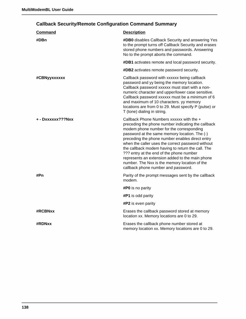
138
MultiModemBL User Guide
Callback Security/Remote Configuration Command Summary
Command Description
#DBn #DB0 disables Callback Security and answering Yesto the prompt turns off Callback Security and erasesstored phone numbers and passwords. AnsweringNo to the prompt aborts the command.
#DB1 activates remote and local password security.
#DB2 activates remote password security.
#CBNyyxxxxxx Callback password with xxxxxx being callbackpassword and yy being the memory location.Callback password xxxxxx must start with a non-numeric character and upper/lower case sensitive.Callback password xxxxxx must be a minimum of 6and maximum of 10 characters. yy memorylocations are from 0 to 29. Must specify P (pulse) orT (tone) dialing in string.
+ - Dxxxxxx???Nxx Callback Phone Numbers xxxxxx with the +preceding the phone number indicating the callbackmodem phone number for the correspondingpassword at the same memory location. The (-)preceding the phone number enables direct entrywhen the caller uses the correct password withoutthe callback modem having to return the call. The??? entry at the end of the phone numberrepresents an extension added to the main phonenumber. The Nxx is the memory location of thecallback phone number and password.
#Pn Parity of the prompt messages sent by the callbackmodem.
#P0 is no parity
#P1 is odd parity
#P2 is even parity
#RCBNxx Erases the callback password stored at memorylocation xx. Memory locations are 0 to 29.
#RDNxx Erases the callback phone number stored atmemory location xx. Memory locations are 0 to 29.

139
Appendix D - AT Command Summary
Password Command Summary
Command Description
#Ixxxxxxxxxx Login Password is any keyboard characters (x)(upper/lower case sensitive), minimum 6 andmaximum 10 characters. The default LoginPassword is #IMULTI-TECH.
#Syyyyyyyyyy Setup Password is any keyboard characters (y)(upper/lower case sensitive), minimum 6 andmaximum 10 characters. The default SetupPassword is #SMODEMSETUP.
V.25bis Commands
Command Description
$Vn $V0 returns modem to AT command mode when inV.25bis mode.
$V1 enables V.25bis mode of operation.
$V2 allows modem to receive one V.25bis commandwhile in AT command mode without leaving ATcommand mode.
$V5 DSR follows DTR in V.25bis mode.
$V6 DSR does not follow DTR in V.25bis mode.
CSPs Changes the serial bps rate.
CSP0300 - 300 bpsCSP1200 - 1200 bpsCSP2400 - 2400 bpsCSP4800 - 4800 bpsCSP9600 - 9600 bpsCSP19200 - 19200 bpsCSP38400 - 38400 bpsCSP57600 - 57600 bpsCSP115200 - 115200 bps (1932 and 2834 modelsonly)
CRNdd Dials phone number dd where dd can be up to 20characters (0 through 9, *, #, P, T and :). Phonenumber is checked against the Delayed andForbidden Number lists before dialed.
CRIdd;nn Dials dd same as CRN Command and ignores nnidentification string. The disregard or connect toincoming calls commands are used for auto-answeroperations.
DIC or CIC DIC stops the modem from answering incomingcalls.
CIC causes the modem to answer incoming calls.

140
MultiModemBL User Guide
Appendix E - DIP-Switch Summary
Asynchronous Mode
DIP-Switch Condition Effect
#1 UP* DTR dependent on interfaceDown DTR forced On at all times
#2 UP* Hardware Flow ControlDown Xon/Xoff Flow Control
#3** 2834 Series:
UP -15 dB Transmission (leased line)Down* -9 dB Transmission (leased line)
#3** 1932 and 1432 Series:
UP -10 dB Transmission (leased line)Down* 0 dB Transmission (leased line)
#4 UP* UUCP Spoofing OffDown UUCP Spoofing On
#5 UP* Automatic Answer OnDown Automatic Answer Off
#6 UP* Max throughput OnDown Max throughput Off
#7 UP RTS dependent on InterfaceDown* RTS forced On at all times
#8 UP Disable Command ModeDown* Enable Command Mode
#9 UP Local Digital Loopback OnDown* Remote Digital Loopback On
#10 UP* Dial-Up OperationDown Leased Line Operation
#11 UP "AT" ResponsesDown* Multi-Tech Responses
#12 UP Synchronous Mode OnDown* Asynchronous Mode On
*Factory Default Setting
**Not applicable in BLK models

141
Appendix E - DIP-Switch Summary
Synchronous Mode
DIP-Switch Condition Effect
#1 UP* DTR Dependent On interfaceDown DTR forced On at all times
#2 UP* SDLC Mode OnDown BSC Mode On
#3 UP Command Mode Response OffDown* Command Mode Response On
#4 UP* AS/400 Mode OffDown AS/400 Mode On
#5 UP* Answer Mode OnDown Originate Mode On
#6 UP* Slave Clocking OffDown Slave Clocking On
#7 UP RTS Dependent on interfaceDown* RTS forced on at all times
#8 UP Command Mode OffDown* Command Mode On
#9 UP Local Digital Loopback OnDown* Remote Digital Loopback On
#10 UP* Dial-Up OperationDown Leased Line Operation
#11 UP External Clock selectedDown* Internal Clock selected
#12 UP Synchronous Mode OnDown* Asynchronous Mode On
*Factory Default Setting

142
MultiModemBL User Guide
DIP Switches #13-14
Note: The modem baud rate command ($MBn) overrides the setting of these speed selectionswitches (DIP switches #13 and #14).
2834 Series:
SWITCH CONDITION EFFECT
#13/#14 UP/UP* 28.8 K bps Operation
#13/#14 DOWN/UP 19.2 K bps Operation
#13/#14 UP/DOWN 14.4 K bps Operation
#13/#14 DOWN/DOWN 9600 bps Operation
1932 Series:
SWITCH CONDITION EFFECT
#13/#14 UP/UP* 19.2 K bps Operation
#13/#14 DOWN/UP 14.4 K bps Operation
#13/#14 UP/DOWN 9600 bps Operation
#13/#14 DOWN/DOWN 2400 bps Operation
1432 Series:
SWITCH CONDITION EFFECT
#13/#14 UP/UP* 14.4 K bps Operation
#13/#14 DOWN/UP 9600 bps Operation
#13/#14 UP/DOWN 4800 bps Operation
#13/#14 DOWN/DOWN 2400 bps Operation
DIP Switches #15-16
#15 UP* CD/DSR from Interface
#15 DOWN CD/DSR Forced On
#16 UP 2-Wire Leased Line
#16 DOWN* 4-Wire Leased Line
*Standard Factory Default Setting

143
Appendix F - S-Register Summary
Appendix F - S-Register Summary
S-REGISTER UNIT RANGE DEFAULT DESCRIPTION
S0 1 ring 0-255 1 Sets number of rings before modemanswers.
S1 1 ring 0-255 0 Counts rings which have occurred.
S2 ASCII 0-127 43 Sets Escape Code character (default is plus+ sign).
S3 ASCII 0-127 13 Sets character recognized as RETURN(default is CTRL-M).
S4 ASCII 0-127 10 Sets character recognized as LINE FEED(default is CTRL-J).
S5 ASCII 0-32,127 8 Sets character recognized as BACKSPACE(default is CTRL-H).
S6 1 second 2-255 2 Determines wait-time for4-255** 4** dial tone.4-7*** 4***
S7 1 second 1-255 45 Determines how long modem waits for1-45 55* carrier before aborting call.1-55*
S8 1 second 0-255 2 Sets pause time caused by a comma4-255** 4** character in a dial command.4-7*** 4***
S9 100 mSec 1-255 6 Sets carrier detect response time.
S10 100 mSec 1-255 7 Sets delay time between when carrier is lostand when modem disconnects.
S11 1 mSec 1-255 70 Sets time duration of and spacing between80-255* 80* tones in tone-dialing.
S13 ASCII 0-127 37 Defines Remote Configuration EscapeCharacter
S15 Sec 10-255 20 Defines time delay for Callback attemptsafter initial passwords have exchanged.
S16 1 Attempt 1-255 4 Defines the number of Callback attempts1-2*** 2*** after initial passwords have exchanged
between modems.
S17 10 mSec 0-2.5 250 mSec Defines length of break time (space) to PC.
S18 30 min 10-255 30 Defines how often leased-line is checkedand restoral attempted.
S19 min 0-255 1 Timer used in dial backup mode. Specifiestime duration modem attempts to restoreleased line connection.
* Values for International and DOC units only.** International only.*** Model MT2834BLK only.
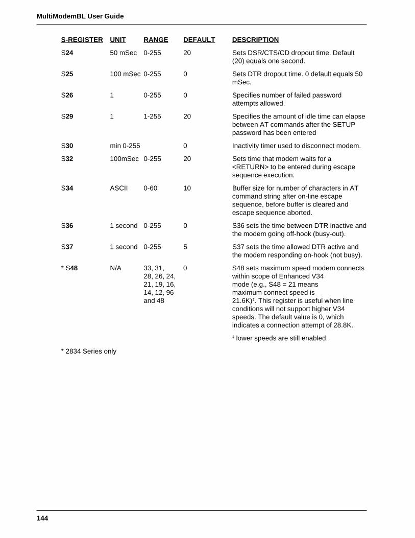
144
MultiModemBL User Guide
S-REGISTER UNIT RANGE DEFAULT DESCRIPTION
S24 50 mSec 0-255 20 Sets DSR/CTS/CD dropout time. Default(20) equals one second.
S25 100 mSec 0-255 0 Sets DTR dropout time. 0 default equals 50mSec.
S26 1 0-255 0 Specifies number of failed passwordattempts allowed.
S29 1 1-255 20 Specifies the amount of idle time can elapsebetween AT commands after the SETUPpassword has been entered
S30 min 0-255 0 Inactivity timer used to disconnect modem.
S32 100mSec 0-255 20 Sets time that modem waits for a<RETURN> to be entered during escapesequence execution.
S34 ASCII 0-60 10 Buffer size for number of characters in ATcommand string after on-line escapesequence, before buffer is cleared andescape sequence aborted.
S36 1 second 0-255 0 S36 sets the time between DTR inactive andthe modem going off-hook (busy-out).
S37 1 second 0-255 5 S37 sets the time allowed DTR active andthe modem responding on-hook (not busy).
* S48 N/A 33, 31, 0 S48 sets maximum speed modem connects28, 26, 24, within scope of Enhanced V3421, 19, 16, mode (e.g., S48 = 21 means14, 12, 96 maximum connect speed isand 48 21.6K)‡. This register is useful when line
conditions will not support higher V34speeds. The default value is 0, whichindicates a connection attempt of 28.8K.
‡ lower speeds are still enabled.
* 2834 Series only
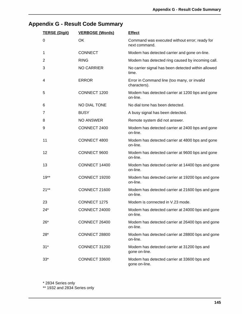
145
Appendix G - Result Code Summary
Appendix G - Result Code Summary
TERSE (Digit) VERBOSE (Words) Effect
0 OK Command was executed without error; ready fornext command.
1 CONNECT Modem has detected carrier and gone on-line.
2 RING Modem has detected ring caused by incoming call.
3 NO CARRIER No carrier signal has been detected within allowedtime.
4 ERROR Error in Command line (too many, or invalidcharacters).
5 CONNECT 1200 Modem has detected carrier at 1200 bps and goneon-line.
6 NO DIAL TONE No dial tone has been detected.
7 BUSY A busy signal has been detected.
8 NO ANSWER Remote system did not answer.
9 CONNECT 2400 Modem has detected carrier at 2400 bps and goneon-line.
11 CONNECT 4800 Modem has detected carrier at 4800 bps and goneon-line.
12 CONNECT 9600 Modem has detected carrier at 9600 bps and goneon-line.
13 CONNECT 14400 Modem has detected carrier at 14400 bps and goneon-line.
19** CONNECT 19200 Modem has detected carrier at 19200 bps and goneon-line.
21** CONNECT 21600 Modem has detected carrier at 21600 bps and goneon-line.
23 CONNECT 1275 Modem is connected in V.23 mode.
24* CONNECT 24000 Modem has detected carrier at 24000 bps and goneon-line.
26* CONNECT 26400 Modem has detected carrier at 26400 bps and goneon-line.
28* CONNECT 28800 Modem has detected carrier at 28800 bps and goneon-line.
31* CONNECT 31200 Modem has detected carrier at 31200 bps andgone on-line.
33* CONNECT 33600 Modem has detected carrier at 33600 bps andgone on-line.
* 2834 Series only** 1932 and 2834 Series only
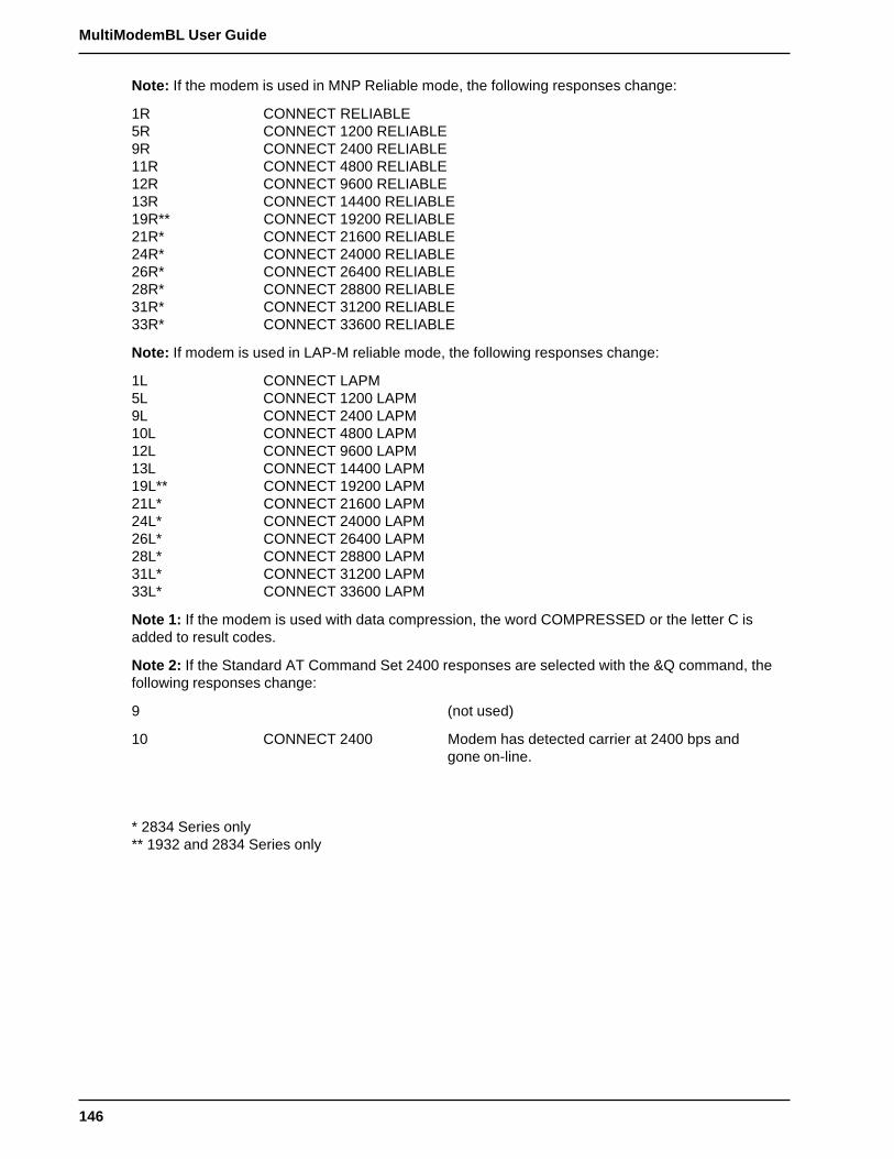
146
MultiModemBL User Guide
Note: If the modem is used in MNP Reliable mode, the following responses change:
1R CONNECT RELIABLE5R CONNECT 1200 RELIABLE9R CONNECT 2400 RELIABLE11R CONNECT 4800 RELIABLE12R CONNECT 9600 RELIABLE13R CONNECT 14400 RELIABLE19R** CONNECT 19200 RELIABLE21R* CONNECT 21600 RELIABLE24R* CONNECT 24000 RELIABLE26R* CONNECT 26400 RELIABLE28R* CONNECT 28800 RELIABLE31R* CONNECT 31200 RELIABLE33R* CONNECT 33600 RELIABLE
Note: If modem is used in LAP-M reliable mode, the following responses change:
1L CONNECT LAPM5L CONNECT 1200 LAPM9L CONNECT 2400 LAPM10L CONNECT 4800 LAPM12L CONNECT 9600 LAPM13L CONNECT 14400 LAPM19L** CONNECT 19200 LAPM21L* CONNECT 21600 LAPM24L* CONNECT 24000 LAPM26L* CONNECT 26400 LAPM28L* CONNECT 28800 LAPM31L* CONNECT 31200 LAPM33L* CONNECT 33600 LAPM
Note 1: If the modem is used with data compression, the word COMPRESSED or the letter C isadded to result codes.
Note 2: If the Standard AT Command Set 2400 responses are selected with the &Q command, thefollowing responses change:
9 (not used)
10 CONNECT 2400 Modem has detected carrier at 2400 bps andgone on-line.
* 2834 Series only** 1932 and 2834 Series only

147
Appendix H - V.25bis Operation
Appendix H - V.25bis Operation
Chapter 5 described a set of commands which let the modem dial, hang-up, and be configured forvarious applications. However, these commands, the AT command set, are only functional when theDTE transmits data asynchronously. That is, they cannot be used with synchronous equipment suchas that found in IBM's Binary Synchronous Communications (BSC) and Synchronous Data LinkControl (SDLC)* environments.
The ITU V.25bis commands provide you with an alternate set of commands and responses to thosedescribed in Chapter 5 for applications in which the DTE is synchronous. V.25bis commands supportdialing functions in asynchronous or synchronous mode according to the recommendations of theITU; however, the AT commands are understood to reign in the asynchronous world, while theV.25bis commands are relegated to the synchronous world of datacomm. If you need to establish adatacomm link over Public Switched Telephone Network (PSTN) dial-up services, and yourequipment outputs a synchronous data stream, V.25bis commands are essential. V.25bis mode ATcommands do not include any modem configuration commands. You can execute normal ATcommands in V.25bis mode for modem configuration.
Delayed and Forbidden Numbers
V.25bis provides the facility to delay failed call retry attempts by putting numbers that failed toconnect on a special Delayed Number list. Subsequent dialing of these numbers will be delayed (timespecified by a country regulation) and an appropriate message displayed. If the number is retriedmore than the maximum allowed number of times (number is also specified by country regulation), itis placed on the Forbidden Numbers list, and no further retries will be allowed. When the ForbiddenNumbers list is full, no dialing is allowed and a CFIFF indication is given. The modem in AT commandmode will respond with NO CARRIER. If country regulations require that the Forbidden Numbers listbe checked in AT mode, then NO CARRIER will be the response to a dial attempt in AT mode.Numbers will also be put on the Forbidden Numbers list if the Delayed Numbers list is full and a newnumber fails for the first time. In that case, the new number will be added to the Delayed Number listand the oldest existing number added to the Forbidden Numbers list. Numbers are removed from theForbidden Numbers list by after a certain time has past (also by country regulation).
Some country regulations have numbers remain on the Forbidden Numbers list permanently. TheDelayed Number and Forbidden Numbers lists are eight numbers long (20 characters each).
V.25bis Operation
Operation in V.25bis mode is similar to AT command mode in that certain DIP-Switch functions areimportant to its operation. V.25bis does not include any speed detection for asynchronous mode, sowhen you are giving commands, you must stay in your initial speed (i.e., if you change your terminalspeed while entering an AT command, you will get no responses). In synchronous mode, the modemsupplies the clock, so the synchronous terminal “knows” the speed.
You must be in V.25bis mode for the commands described here to function. Most AT commands willalso function, except those associated with dialing such as ATD, ATN, ATO, and ATU. To get intoV.25bis mode, you type AT$V1. At this point your modem does no more speed or parity detection(things associated with asynchronous operation). To get out of V.25bis mode and back into ATcommand mode, enter AT$VO. The AT$V2 command allows you to run one V.25bis command fromAT command mode withoutleaving AT command mode.
There is no command to select between asynchronous and synchronous V.25bis operation. Theposition of DIP-Switch #12 selects between modes. For synchronous mode, DIP-Switch #12 must beUP, and the AT command mode enabled.
148
MultiModemBL User Guide
Another asynchronous mode concern is the problem of connecting at a different speed than thespeed at which the serial port is set. If your modem port speed is different from the serial port speed,you must either:
1) Enable speed conversion and have flow control on, or
2) Enable connect responses (with the ATX1 command) and change the serial baud rateafter receiving a connect message.
If the $VD1 command is entered when in Auto-Answer mode, the modem answers immediately uponreceiving the first ring.
There is no disconnect message (NO CARRIER) if a normal connection is made.
V.25bis Set-Up and Initialization
Before you operate your modem in the V.25bis mode, you need to make sure it is set up properly(various RS-232 lines such as DSR and CTS act as specified in the V.25bis standard). Setupinvolves proper DIP-Switch settings and soft-switches (software controlled conditions).
V.25bis DIP-Switches
#1 Unforced DTR
#2 NA
#3 NA
#4 NA
#5 Auto-Answer enabled
#6 Async - Max throughput setSync - Slave Clocking unforced
#8 Command Mode forced
#9 Digital Loopback Off
#10 Dial-Up
#11 Async - AT/Multi-Tech Resp.
#12 Async/Sync mode set per requirements

149
Appendix H - V.25bis Operation
V.25bis Mode AT Commands
The following commands will either alter standard V.25bis behavior (so you must be careful in theiruse) or they are not allowed, as indicated. All other commands can be used in V.25bis operation.
A Not Allowed
A/ Not Allowed
A: Not Allowed
D Not Allowed
D...N Not Allowed
$D Alters Operation ($D1 in V25bis is direct call mode)
E Alters Operation
&F Alters Operation (removes modem from asynchronous V.42bis mode)
N Not Allowed
N...N Not Allowed
O Not Allowed
P Not Allowed
T Not Allowed
U Not Allowed
W Not Allowed
X Alters Operation (X0 no connect message, X1 connect message)
, Not Allowed
; Not Allowed
! Not Allowed
@ Not Allowed
+++AT<CR> Not Allowed
V.25bis Responses (Result Codes)
When in V.25bis mode (the AT$V1 command executed), your modem provides you with severalresponses which can help you follow the progress of V.25bis operations. These are similar to theResult Codes associated with AT Command mode operation. The V.25bis responses are in the formof three-character mnemonics as listed below:
INC Incoming Call (same as RING indicator)
VAL A valid V.25bis command has been attempted
DLCt Call delayed for t minutes (number on Delayed list)
CFlrr Call failure indicator where rr equals:
et - Engaged tone (same as BUSY)nt - Call Answered but No Answer Toneab - Call Not Answeredfc - Number on Forbidden Listns - Number not stored in memoryua - User Abortnd - No Dialtoneff - Forbidden List full
LSNmm;dd...dd Phone number in V.25bis memory
LSDmm;dd...dd Phone number on the Delay list
LSFmm;dd...dd Phone number on the forbidden list
CON ssss Connection at ssss speed (if X1 in effect)

150
MultiModemBL User Guide
V.25bis AT Commands
The AT commands associated with V.25bis mode are described as follows. Note that one commandenables and disables V.25bis mode and the rest are only operable in the V.25bis mode.
Enable/Disable V.25bis Mode ($V) Command
The function of the $V command is to select the V.25bis mode in asynchronous mode. (Synchronousmode is set up with switches. For example, the modem could be in AT command mode, (AT$V1),and if synchronous mode is enabled with AT Command mode enabled, then V.25bis mode isselected). Prior to executing this command, make sure that your modem is properly set up to performthe type of operation you will be performing. Refer to the initialization section of this appendix forinformation about modem set-up. When in V.25bis mode, most normal AT commands will alsofunction (except D,N,O and U). V.25bis operates in asynchronous or synchronous modes (dependingon the position of DIP-Switch #12), and does not check for terminal speed (so do not change speedswhile in this mode) or parity. In synchronous mode, speed is not important since the internal clocksprovide synchronization.
To place your modem in V.25bis mode from asynchronous mode, enter the AT$V1 command. Toreturn to AT command mode, enter the AT$V0 command. AT$V2 allows you to run one V.25biscommand from AT command mode without leaving AT command mode (the V.25bis commandfollows $V2 on the command line).
Change Serial Baud Rate (CSP) Command
The CSP command will change the serial baud rate of your modem by entering CSPsssss wheresssss can equal:
0300 = 300 bps1200 = 1200 bps2400 = 2400 bps4800 = 4800 bps9600 = 9600 bps19200 = 19200 bps38400 = 38400 bps57600 = 57600 bps115200 = 115200 bps (1932 and 2834 Series only)
Dial Phone Number Provided (CRN) Command
The CRN command permits the dialing of the phone number immediately following it (from thecommand line). It is similar to the D command of the AT command set, except that the number is firstchecked against the Delayed Number and Forbidden Number list. If permitted, depending on thecountry regulations in effect, the number will then be dialed. For example, if you enter CRN7859875and hit RETURN, your modem will check the two lists. If the number is on the Delayed Numbers list,you can dial that number again after t minutes have passed. If the number is on the Forbidden list, aCFIFC message will be displayed.
You can use various commands from the AT command set within the CRN command line to facilitatethe dialing process, such as P, T, or : for pulse dialing, tone dialing and wait for dial tone. V.25bissupports “smart” dialing.
To dial a phone number, enter CRNdd...dd where dd...dd is the phone number, which can be up to20 characters long using any character on the telephone pad (0 through 9, *, #, P, T, and :).
Some additional dialing characters may be available, based on country regulations.

151
Appendix H - V.25bis Operation
Listing Delayed Phone Numbers (RLD) Command
When a phone number is dialed by a CRN command and a connection is not made, the number isentered in the modem's V.25bis Delayed Number list along with the number of retry attempts. Anyfurther dialing attempts will be delayed some amount of time (determined by the regulations of eachcountry). While the delay is in progress, the modem will give a DLC indication. The list contains eightnumbers. When filled, the next number failing “bumps” off the oldest number on the list onto theForbidden Number list. Numbers on the Delayed Number list that succeed in a connect attempt areremoved. If a certain number of failed attempts occur (the number of failed attempts is specified byeach country), the number is entered into the V.25bis Forbidden Phone Number List. Forbiddenphone numbers cannot be dialed at all. To list the phone numbers on the V.25bis Delayed PhoneNumber List, enter RLD and hit RETURN.
Listing Forbidden Phone Number (RLF) Command
Those phone numbers that have failed to connect the required number of times as specified bycountry regulations are removed from the Delayed Number list and entered onto the V.25bisForbidden Number list. Numbers on the Forbidden Number list cannot be dialed at all for somemaximum amount of time, which is also specified by country regulations. In some countries, the timemight be one hour, and in others the number may never be dialed again. The forbidden list is eightnumbers long, with the newest number replacing the oldest if the memory is full. To list the numbersin the Forbidden list enter RLF and hit RETURN.
Disregard or Connect to Incoming Calls (DIC or CIC) Command
The Disregard or Connect to Incoming Calls commands are used for Auto-Answer operations.Depending on the country regulations, your modem will wait some amount of time or number of ringsbefore answering the call. During that time, you can stop the modem from answering the call byentering the DIC (Disregard Incoming Calls) command. The CIC (Connect to Incoming Calls)command will cause your modem to answer the call (either reversing the effect of a DIC command orsimply have your modem answer the call immediately without waiting the regulation time beforeanswering).
DTR Dialing ($D) Command
DTR Dialing is an alternate method of causing the modem to automatically dial a number. DataTerminal Ready (DTR) is a signal that comes into the modem from the terminal or computer to whichit is connected via pin 20 of the RS-232 interface. In DTR Dialing, the modem will automatically dial astored number as soon as it receives a high DTR signal. The DTR Dialing method is popular whenusing the modem in synchronous applications.
To enable DTR Dialing, enter the command AT$D1 and hit Return. The modem will now dial thephone number you have stored as N0 when it receives a high DTR signal (see the D...N command inChapter 5).DTR must remain high for the duration of the call, until disconnect. To disable DTR Dialing, enter thecommand AT$D0 (or AT$D) and hit RETURN.
When you use DTR Dialing, be sure that DIP-Switch #1 is in the UP position, so that DTR is notforced on.
In addition, when using DTR Dialing in a synchronous application, be sure that DIP-Switch #8 is inthe UP position to disable V.25bis Command mode.
152
MultiModemBL User Guide
ITU V.25bis Country Specific Information
Due to the flexibility of the V.25bis standard, each country may establish specific regulationsgoverning the way operations are handled. The purpose of this document is to detail each country'sspecific regulations that affect operation of V.25bis in Multi-Tech modems.
1. Italy
a) Command/Indication modifications1. Phone number indications include status ;ZPSTTT
a) Z - U, D, or F, for Unrestricted, Delayed or Forbiddenb) P - Delay time if delayedc) S - Number of retries so fard) TTT - Interdiction time to further attempts
b) Delayed and Forbidden list behavior1. 5 retries without delay2. 2 minute delay between next 4 retries3. After 9 retries the number is put on the forbidden list4. 120 minute timer is started on entry to delay list5. When it runs out, the number is removed from which ever list it is on
c) Auto-Answer mode behavior1. Auto-Answer in 5 seconds if no DIC2. Get 10 seconds after DIC to enter CIC3. If 10 seconds times out then no connection is possible
2. Switzerland
a) Command/Indication modification1. Modem must remain on-hook for 5 seconds after disconnect2. Modem must remain on-hook for 5 minutes after 4 consecutive failed calls3. If modem must remain on-hook, then it is “paused”4. If the modem is paused and a call is attempted a PAU indication is given.
a) PAUt Modem is paused for t minutesb) Delayed and Forbidden list behavior
1. 2 minute delay between 4 retries2. After 4 retries the number is put on the forbidden list3. The number remains on the forbidden list forever
c) Auto-Answer behavior1. Auto-Answer mode after 2 rings if no DIC
3. Austria
a) Command/Indication modification (none)b) Delayed and Forbidden list behavior
1. No delay between retries2. After 2 retries to numbers that answer, but give no answer tone (CFINT), the
number is put on the forbidden list3. After 10 retries with busy or no dialtone, the number is put on the forbidden
list4. The number remains on the forbidden list forever5. Delayed and Forbidden Numbers lists are checked when dialing in AT mode.
If dialing is not possible then NO CARRIER is the response.c) Auto-Answer behavior
1. Auto-Answer in 5 seconds if no DIC

153
Appendix H - V.25bis Operation
4. France
a) Command/Indication modification (none)b) Delay and Forbidden list behavior
1. 2 min. delay after 1st call, 4 after 2nd, 6 after 3rd, etc.2. After 5 retries, the number is put on the forbidden list3. The number remains on the forbidden list forever4. Delayed and Forbidden Numbers lists are checked when dialing in AT
command mode. If dialing is not possible then No Carrier is the response.c) Auto-Answer mode behavior
1. Auto-Answer in 5 seconds if no DIC
5. Belgium
a) Command/Indication modification (none)b) Delay and Forbidden list behavior
1. 1 min. delay between calls2. After 4 retries, the number is put on the forbidden list3. The number remains on the forbidden list for 1 hour after entry to forbidden
list4. Delayed and Forbidden Numbers lists are checked when dialing in AT
command mode. If dialing is not possible then No Carrier is the response.c) Auto-Answer behavior
1. Auto-Answer in 5 seconds if no DIC.
6. Singapore
a) Command/indication modifications1. Dialing digit ‘=’ means wait for dialtone (acts the same as ‘:’ in dialing string).
b) Delay and Forbidden list behavior1. 5 retries without delay2. 2 minute delay between next 4 retries3. After 9 retries the number is put on the forbidden list4. 120 minute timer is started on entry to delay list5. When it runs out, the number is removed from whichever list it is on.
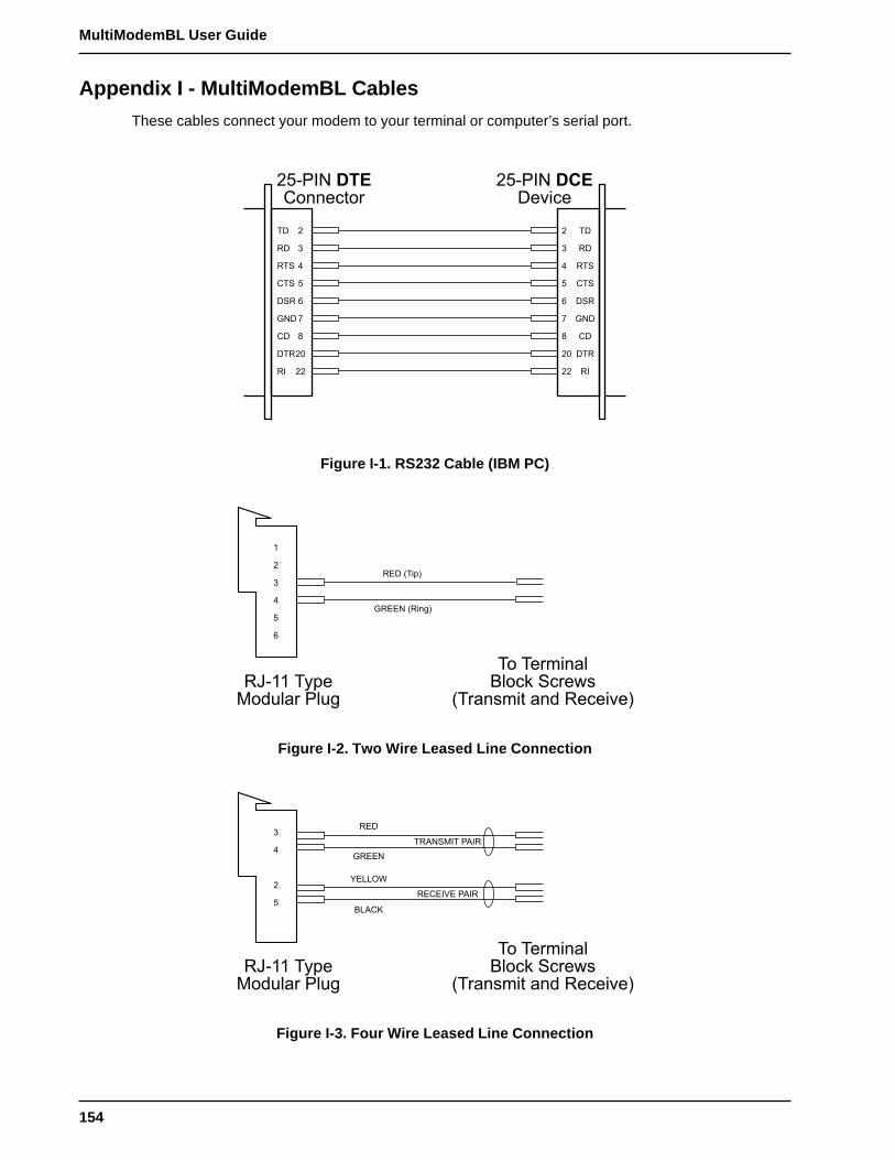
154
MultiModemBL User Guide
Appendix I - MultiModemBL Cables
These cables connect your modem to your terminal or computer’s serial port.
�7�02- ��*�''�%���
�7�02- ��$�>�%�
� �$
�$
���
7 *��
� $��
6 .-$
� *$
�� $��
�� �2
�$ �
�$
���
*�� 7
$�� �
.-$6
*$ �
$����
�2 ��
Figure I-1. RS232 Cable (IBM PC)
�<��� �?��������� 0��(
�� ���&�'�����%; �%��=�
����'�&�� �'� ��%��>�#
�
�
7
�
�3$ ����#
.�33- ���'(#
Figure I-2. Two Wire Leased Line Connection
�<��� �?��������� 0��(
�� ���&�'�����%; �%��=�
����'�&�� �'� ��%��>�#
�
7
�3$
.�33-
@3��14
��,*A
��,-��2� 0,2�
�3*32 3 0,2�
Figure I-3. Four Wire Leased Line Connection

155
Appendix J - RS-232C Interface Specifications
�7 01��,�3 $�/�
� 01�!�2-2�$2-
�$ �
�*
���
*�� 7
.-$6
� +�'��)�;� 1��
� +�'��)�;� 2'
.-$
� .-$
�$
7 �*
� � �
� �
� �
� 01�!�2-2�$2-53�,�3
Figure I-4. MAC Cable

156
MultiModemBL User Guide
Appendix J - RS-232C Interface Specifications
The modem's RS-232C interface circuits have been designed to meet the electrical specificationsgiven in EIA (Electronic Industries Association) RS-232C standards. All signals generated by themodem are approximately 10 volts when measured across a load of 3000 ohms or greater. Thereceiving circuits of the modem will accept signals in the 3 to 25 volt range. The voltage thresholdsare:
Negative = voltage more negative than 3 volts with respect to signal ground
Positive = voltage more positive than +3 volts with respect to signal ground
SIGNAL INFORMATION: NEGATIVE POSITIVE
Binary State One ZeroSignal Condition Mark SpaceControl and Timing Function Off On
The input impedances of all modem circuits which accept signals from the data processing terminalor CPU equipment have DC resistances of 4.7K. For more specific details, consult the EIA RS-232Cstandard itself.
The following chart lists the EIA RS-232C interface pins and circuits present on the modem'sRS232C Interface connector. All other pins are unused.
Pin Designation eia CCITT signal FunctionAssignment circuit circuit source
1 PG -- 101 -- Protective Ground2 SD BA 103 DTE Transmitted Data3 RD BB 104 DCE Received Data4 RTS CA 105 DTE Request to Send5 CTS CB 106 DCE Clear to Send6 DSR CC 107 DCE Data Set Ready7 SG AB 102 -- Signal Ground8 CD CF 109 DCE Carrier Detect9** +v +v -- DCE Test Voltage12 HS -- -- DCE High Speed15*** TC DB 114 DCE Transmit Clock17*** RC DD 115 DCE Receive Clock20 TR**** CD 108/2 DTE Terminal Ready22 RI CE 125 DCE Ring Indicator24 XTC DA 113 DTE External Transmit Clock25 OOS CN 142 DTE Terminal Busy
** Pin 9 need not be present in your RS-232C cable
*** Pins 15 and 17 are necessary only for synchronous operation
**** Also known as DTR (Data Terminal Ready)
The computer or terminal should be supplied with a cable terminated with a Cinch DB-25P (orequivalent) connector mounted in a Cinch DB-51226-1 (or equivalent) hood assembly as specified bythe EIA RS-232C standard.

157
Appendix J - RS-232C Interface Specifications
Functional Description of RS-232C Signals:
Transmitted Data - Pin 2, SD (BA)
Direction: to modem
Signals on this circuit are generated by the customer's terminal and transferred to the transmitter ofthe modem. A positive signal is a space (binary 0) and a negative signal is a mark (binary 1). Thetransmitting terminal should hold this line in the marking state when no data is being transmitted,including intervals between characters or words. The TRANSMIT (XMT) LED indicates the status ofthis circuit.
Received Data - Pin 3, RD (BB)
Direction: from modem
The lead is the data output of the modem. Data signals received from the remote modem arepresented on this line. When no carrier signal is being received (pin 8 negative), this line will beforced into a marking condition. The RECEIVE (RCV) LED indicates the status of this signal.
Request To Send - Pin 4, RTS (CA)
Direction: to modem
The RTS signal indicates to the modem that the computer or terminal has data that it wants totransmit.
Clear To Send - Pin 5, CTS (CB)
Direction: from modem
The CTS line indicates to the terminal that the modem will transmit any data present on the TransmitData line (pin 2).
Data Set Ready - Pin 6, DSR (CC)
Direction: from modem
DSR On indicates that the modem is in the data mode and is connected to the communicationschannel. This signal will be on during analog-loop-test mode.
Signal Ground - Pin 7, SG (AB)
The SG lead is connected to signal ground of the modem. It establishes the common groundreference for all other interface signals.
Data Carrier Detect - Pin 8, CD (CF)
Direction: from modem
DCD On (positive voltage) indicates that data carrier has been received from the other modem. Thiscircuit will not normally turn on in the presence of message circuit noise or out-of-band signals. Thereis a one second delay between when the carrier tone has been detected and when the CD circuit isturned on.
This signal goes off if received data carrier falls below the receiver threshold for more than 37 mSec.When CD is off, the Received Data circuit (pin 3) is held to the marking state.

158
MultiModemBL User Guide
Test Voltage - Pin 9, XV
Direction: from modem
The XV lead has 330 ohms of resistance to +12 volts DC. This lead may be used to strap othersignals high. For example, if the terminal does not supply a DTR (Data Terminal Ready) signal, Pin 9may be jumpered to Pin 20 (DTR) on the RS-232 connector or in the cable to force DTR on.
Transmit Clock - Pin 15, TC (DB)
Direction: from modem
The TC signal is provided only when the modem is used in the synchronous mode. The clock is asquare wave and is used to provide the computer or terminal with timing information for its TransmitData circuit (pin 2). This clock will be provided on the interface at all times when the modem is inSynchronous mode.
The first signal element of the Transmitted Data signal should be presented by the terminal on thefirst positive (Off to On) transition of TC which occurs after the CTS circuit on pin 5 has turned on.The transmitted data is sampled by the modem on negative transitionof TC.
Receive Clock - Pin 17, RC (DD)
Direction: from modem
The RC signal has the same characteristic of Transmit Clock, with the exception that it is used toprovide the computer or terminal with timing information for its Receive Data (pin 3) circuit. Thenegative transition (On to Off) of RC indicates the center of each signal element on the ReceivedData circuit.
Data Terminal Ready - Pin 20, TR or DTR (CD)
Direction: to modem
This signal (TR or DTR) provides a means for the terminal or computer to control the modem'sconnection to the communications channel. A high DTR signal is required by the modem to be able tocommunicate. Turning DTR off for more than 50 mSec will force the modem to disconnect.
The most common use of DTR is in automatic answer applications. A high DTR signal is required bythe modem to answer a call. A frequently used method is to have the computer turn on DTR inresponse to RI (Ring Indicator), which allows the modem to answer. Later, DTR is turned off at theconclusion of the log off procedure, which forces the modem to disconnect, enabling it to receiveanother call. In non auto answer applications it is advisable to leave DTR on using the modem's DIP-switch option. This is the standard factory setting. An alternative is to provide a constant high DTRfrom the terminal or computer. The Data Terminal Ready (DTR) LED indicates the status of thissignal.
Ring Indicator - Pin 22, RI (CE)
Direction: from modem
This signal will remain on for the duration of the ringing signal. When a ring signal is received by themodem, the modem will automatically answer after the first ring. The modem will answer after aspecified number of rings which can be programmed in AT Command mode, but if none is specified,the modem will answer after the first ring.

159
Appendix J - RS-232C Interface Specifications
External Transmit Clock - Pin 24, XTC
Direction: to modem
Supplies the same function as transmit clock on Pin 15.
Terminal Busy (Out of Service) - Pin 25, OOS
Direction: to modem
The Terminal Busy (OOS) circuit is not defined in the RS-232C standard, but is used by us and mostmanufacturers to make the phone lines busy to incoming phone calls. Pin 25 is not normallyconnected to the RS-232C interface when shipped from the factory; it can be ordered connected asan option. If pin 25 is connected and is brought high, the modem will be placed Off Hook, and busy toincoming calls.
160
MultiModemBL User Guide
Appendix K - Regulatory Information
Compliance with BABT Requirements
Approved for connection to telecommunications system specified in the instructions for use subject tothe conditions set out in them.
Warning: Interconnection directly, or by way of other apparatus, of ports marked "SAFETYWARNING see instructions for use" with ports marked or not so marked may produce hazardousconditions on the network. Advice should be obtained from a competent engineer before such aconnection is made.
This apparatus has been approved for the use of the following facilities:
• Auto-calling
• Loop disconnect and MF dialing
• Phone number storage and retrieval by a predetermined code
• Operation in the absence of proceed indication
• Automatic storage of last number dialed
• Tone detection-busy
• Auto clear from the originating end
• DTR dialing
• Modem
• PBX timed break register recall
Compliance with BS6305 Clause 6.2, BS6320 Clause 7.2, and BABT/SITS/82/005S/D
a. The modem is suitable for connection to the Public Switched Telephone Network (PSTN)provided by British Telecommunications plc or Kingston Communications (Hull) plc. Circuitsupply by British Communications, Mercury Communication, or Hull City Council. Only directexchange lines may be used, not shared service.
b. The modem is suitable for household, office, and similar general indoor use. It is not suitable foruse as an extension to a payphone.
c. BT lines supplied must support either loop disconnect or multifrequency tone signalling.
d. REN (Ringer Equivalence Number).
The REN value of a unit is calculated from 3/n where n is the total number of units which can beconnected in parallel which will still cause the standard bell (as defined in BS6305 Appendix D) toring.
REN values of less than 0.3 cannot be assigned.
REN = 1
If a telephone or other device is connected in parallel with the modem, the combined REN must notexceed 4. A BT supplied telephone may be assumed to have REN of 1.0 unless otherwise noted.
The approval of this modem for connection to the British Telecom public switched telephone networkis INVALIDATED if the apparatus is subject to any modification in any material way not authorized byBABT or if it is used with or connected to:
i. internal software that has not been formally accepted BABT.
ii. external control software or external control apparatus which cause the operation of the modemassociated call set-up equipment to contravene the requirements of the standard set out inBABT/SITS/82/005S/D.
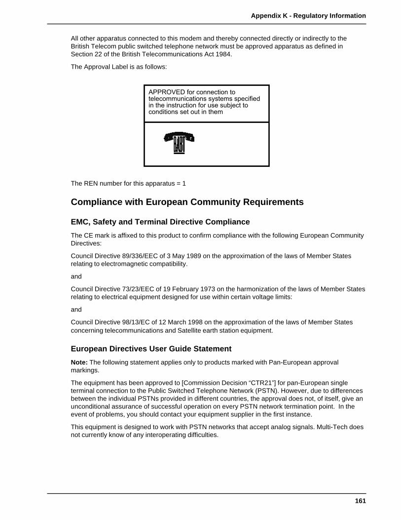
161
Appendix K - Regulatory Information
All other apparatus connected to this modem and thereby connected directly or indirectly to theBritish Telecom public switched telephone network must be approved apparatus as defined inSection 22 of the British Telecommunications Act 1984.
The Approval Label is as follows:
,00�1 3$ :�� %�''�%���' ������%�&&�'�%����'� �?���&� ���%�:����' �)� �'����%���' :�� ��� ���B�%� ��%�'�����'� ��� ��� �' �)�&
The REN number for this apparatus = 1
Compliance with European Community Requirements
EMC, Safety and Terminal Directive Compliance
The CE mark is affixed to this product to confirm compliance with the following European CommunityDirectives:
Council Directive 89/336/EEC of 3 May 1989 on the approximation of the laws of Member Statesrelating to electromagnetic compatibility.
and
Council Directive 73/23/EEC of 19 February 1973 on the harmonization of the laws of Member Statesrelating to electrical equipment designed for use within certain voltage limits:
and
Council Directive 98/13/EC of 12 March 1998 on the approximation of the laws of Member Statesconcerning telecommunications and Satellite earth station equipment.
European Directives User Guide Statement
Note: The following statement applies only to products marked with Pan-European approvalmarkings.
The equipment has been approved to [Commission Decision “CTR21”] for pan-European singleterminal connection to the Public Switched Telephone Network (PSTN). However, due to differencesbetween the individual PSTNs provided in different countries, the approval does not, of itself, give anunconditional assurance of successful operation on every PSTN network termination point. In theevent of problems, you should contact your equipment supplier in the first instance.
This equipment is designed to work with PSTN networks that accept analog signals. Multi-Tech doesnot currently know of any interoperating difficulties.
162
MultiModemBL User Guide
International Modem Restrictions
Some dialing and answering defaults and restrictions may vary for international modems. Changingsettings may cause a modem to become non-compliant with national telecom requirements inspecific countries. Also note that some software packages may have features or lack restrictions thatmay cause the modem to become non-compliant.
New Zealand Telecom Warning Notice
Use of pulse dialing, when this equipment is connected to the same line as other equipment, maygive rise to ‘bell tinkle’ or noise and may also cause a false answer condition. Should such problemsoccur, the user should NOT contact the Telecom Faults Service. The preferred method of dialing is touse DTMF tones, as this is faster than pulse (decadic) dialing and is readily available on almost allNew Zealand telephone exchanges.
Warning Notice: No ‘111’ or other calls can be made from this device during a mains power failure.

163
Appendix K - Regulatory Information
FCC Regulations for Telephone Line Interconnection
1. This equipment complies with Part 68 of the Federal Communications Commission (FCC) rules.On the outside surface of this equipment is a label that contains, among other information, theFCC registration number and ringer equivalence number (REN). If requested, this informationmust be provided to the telephone company.
2. As indicated below, the suitable jack (Universal Service Order Code connecting arrangement) forthis equipment is shown. If applicable, the facility interface codes (FIC) and service order codes(SOC) are shown.An FCC-compliant telephone cord and modular plug is provided with thisequipment. This equipment is designed to be connected to the telephone network or premiseswiring using a compatible modular jack which is Part 68 compliant. See installation instructionsfor details.
3. The ringer equivalence number (REN) is used to determine the quantity of devices which may beconnected to the telephone line. Excessive REN’s on the telephone line may result in the devicesnot ringing in response to an incoming call. In most, but not all areas, the sum of the REN’sshould not exceed five (5.0). To be certain of the number of devices that may be connected tothe line, as determined by the total REN’s, contact the telephone company to determine themaximum REN for the calling area.
4. If this equipment causes harm to the telephone network, the telephone company will notify you inadvance. But if advance notice isn’t practical, the telephone company will notify the customer assoon as possible. Also, you will be advised of your right to file a complaint with the FCC if youbelieve it is necessary.
5. The telephone company may make changes in its facilities, equipment, operations, or proceduresthat could affect the operation of the equipment. If this happens, the telephone company willprovide advance notice in order for you to make necessary modifications in order to maintainuninterrupted service.
6. If trouble is experienced with this equipment (the model of which is indicated below) pleasecontact Multi-Tech Systems, Inc. at the address shown below for details of how to have repairsmade. If the trouble is causing harm to the telephone network, the telephone company mayrequest you remove the equipment from the network until the problem is resolved.
7. No repairs are to be made by you. Repairs are to be made only by Multi-Tech Systems or itslicensees. Unauthorized repairs void registration and warranty.
8. This equipment cannot be used on public coin service provided by the telephone company.Connection to Party Line Service is subject to state tariffs. (Contact the state public utilitycommission, public service commission or corporation commission for information.)
9. If so required, this equipment is hearing-aid compatible.
Trade Name: MultiModemIITM
Model Number: MT2834BL, MT1932BL, MT1432BLFCC Registration #: AU7USA-20673-MM-E (2834 Series)
AU7USA-75640-MM-E (1932 Series)AU7USA-73205-FA-E (1432 Series)
Ringer Equivalence: 0.3B (2834 Series)0.8B (1932 and 1432 Series)
Modular Jack (USOC): RJ11C or RJ11W (single line)Service Center in USA: Multi-Tech Systems, Inc.
2205 Woodale DriveMounds View, Minnesota 55112 U.S.A.(612) 785-3500 or (800) 328-9717U. S. FAX 612-785-9874Fax-Back Service (612) 717-5888Technical Support (800) 972-2439BBS (612) 785-3702 or (800) 392-2432Internet Address: http://www.multitech.com
164
MultiModemBL User Guide
Canadian Limitations Notice
Notice: The ringer equivalence number (REN) assigned to each terminal device provides anindication of the maximum number of terminals allowed to be connected to a telephone interface. Thetermination of a interface may consist of any combination of devices subject only to the requirementthat the sum of the ringer equivalence numbers of all the devices does not exceed 5.
Notice: The Industry Canada label identifies certificated equipment. This certification means that theequipment meets certain telecommunications network protective, operational and safetyrequirements. The Industry Canada does not guarantee the equipment will operate to the user’ssatisfaction.
Before installing this equipment, users should ensure that it is permissible to be connected to thefacilities of the local telecommunications company. The equipment must also be installed using anacceptable method of connection. The customer should be aware that compliance with the aboveconditions may not prevent degradation of service in some situations.
Repairs to certified equipment should be made by an authorized Canadian maintenance facilitydesignated by the supplier. Any repairs or alterations made by the user to this equipment, orequipment malfunctions, may give the telecommunications company cause to request the user todisconnect the equipment.
Users should ensure for their own protection that the electrical ground connections of the powerutility, telephone lines and internal metallic water pipe system, if present, are connected together.This precaution may be particularly important in rural areas.
Caution: Users should not attempt to make such connections themselves, but should contact theappropriate electric inspection authority, or electrician, as appropriate.
Class A Statement
FCC Part 15
This equipment has been tested and found to comply with the limits for a Class A digital device,pursuant to Part 15 of the FCC Rules. These limits are designed to provide reasonable protectionagainst harmful interference when the equipment is operated in a commercial environment. Thisequipment generates, uses, and can radiate radio frequency energy and, if not installed and used inaccordance with the instruction manual, may cause harmful interference to radio communications.Operation of this equipment in a residential area is likely to cause harmful interference in which casethe user will be required to correct the interference at his own expense.
This device complies with Part 15 of the FCC rules.
Operation is subject to the following two conditions:
(1) This device may not cause harmful interference.
(2) This device must accept any interference that may cause undesired operation.
Warning: Changes or modifications to this unit not expressly approved by the party responsible forcompliance could void the user’s authority to operate the equipment.
Industry Canada
This Class A digital apparatus meets all requirements of the Canadian Interference-CausingEquipment Regulations.
Cet appareil numerique de la classe A respecte toutes les exigences du Reglement sur le materielbrouilleur du Canada.

165
Index
IndexSymbols
&E0 ....................................................................32&E1 ....................................................................32&E14 ..................................................................32&T command .................................................... 10116550 UART and Windows 3.1 ..........................292 Wire/ 4 Wire Operation .................................. 1142 Wire/4 Wire Operation ................................... 114
A
Abort Timer .........................................................79Accessories ......................................................122AGC Dynamic Range .........................................15Answer Mode .....................................................64Answer/Originate - Voice/Data Toggle Switch ....33AS/400 Mode ................................................... 110ASCII code .........................................................30Assign Passwords Callback Phone for Numbers(#CBN) ...............................................................93Asynchronous Word Lenth Selection ($EB) .......68Asynchronous/Synchronous Operation ............ 113AT .......................................................................29AT Command and S-Register Summary ............86AT Commands ....................................................44"AT" Responses/Multi-Tech Responses ........... 113Auto-answer ................................................ 30, 31Auto-Reliable Buffering ($A) ...............................64Auto-Reliable Mode (&E1)..................................63
B
Backspace Character .........................................79Basic Result Code ..............................................57Basic/Extended Result Codes ............................57Baud Adjust ($BA) ..............................................70Baud rate
Serial port .......................................................31BBS ..................................................................120Bell/V.21 Tone ....................................................58BREAK AT<CR> ................................................74British Telecom ................................................. 160British Telecommunications pic ........................160Buffer Length of Command Mode...After On-lineEsca ...................................................................83Bulletin board systems ......................... 29, 31, 32
C
Call waiting ....................................................... 127Callback Attempts ..............................................81Callback Operational Sequence Procedures .....91Callback Password and Dial Back Phone NumberEntry ...................................................................90Callback Retry Attempts .....................................95
Callback Security Enable/Disable (#DB) ............93Callback Time Delay ................................... 81, 95"Calling Card" Detect Tones ($) .........................52Carrier Detect Control (&C) ................................61Carrier Detect Response Time ...........................80Carrier Detect/DSR Forcing ............................. 114Carrier Frequencies ...........................................14Carrier Loss Disconnect Delay Time ..................80Change LOGIN Password (#I) ...........................93Change Serial Baud Rate (CSP) Command .... 150Change SETUP Password (#S) .........................93Changing Break Time .........................................81Clear To Send...................................................157Cleardown at Disconnect ...................................59COM ports
COM2 ...................................................... 29, 31COMM.DRV ..................................... 29, 127, 128Command Buffer ................................................13"Command mode" ..............................................43Command string .................................................30Command Summary ........................................ 131Commands
Attention code .................................................29Auto-Reliable mode ........................................32Data compression ...........................................32Load default configuration ..............................30Modem reset ...................................................29Non-Error Correction mode ............................32Reliable mode .................................................32
Compatibility .......................................................12CompuServe ........................................ 28, 29, 32CompuServe/Internet .......................................121Computer-or Terminal-Initiated Flow Control (Pacin69Connectors .........................................................15Continuous Redial (A or :) ..................................49Controls ..............................................................15CTS Control (&R) ...............................................61CTS signal ..........................................................31CTS/RTS Interaction Control (&RF) ...................62CYBERC.ZIP......................................................29
D
Data Carrier Detect ..........................................157Data Compression ...................................... 13, 32Data Compression Commands ..........................69Data Format .......................................................12Data Rates .........................................................12Data Set Ready ................................................157Data Set Ready Control (&S) .............................61Data Terminal Ready ........................................ 158Data Terminal Ready Control (&D) .....................61Datacomm software ....... 28, 29, 30, 31, 32, 124
Configuration ........................................... 29, 31dB Transmission Levels ................................... 110Delayed and Forbidden Numbers ....................147

166
MultiModemBL User Guide
Diagnostics .........................................................15Dial (D) ...............................................................49Dial Phone Number Provided (CRN) Command150Dial Pulse and Tone-Dial Frequencies ............. 130Dialing a Stored Number (N) ..............................49Dialing/On-Line/Answering .................................28Digital Loopback Test ................................ 98, 112Dimensions ........................................................15DIP-Switch Summary .......................................140DIP-Switches.................................................... 115Disregard or Connect to Incoming Calls (DIC or CIC151DSR/CD Interaction Control (&SF) .....................62DTR Dialing ($D) ................................................49DTR Dialing ($D) Command ............................ 151DTR Dropout Time .............................................82DTR signal .........................................................31Dual-Tone Multi-Frequency dialing .....................50“dumb” dialing.....................................................57
E
echnical Specifications .......................................12Enable/Disable Auto-Answer ............................ 111Enable/Disable Auto-Reliable Fallback Character65Enable/Disable Command Mode ..................... 112Enable/Disable V.25bis Mode ($V) Command .150Enable/Suppress Responses ...........................109Erase Callback Password (#RCBNxx) ...............94Erase Callback Phone Number (#RDNxx) .........94Error Correction ........................................... 12, 32Error correction ..................................................32Escape Code Character .....................................78Escape Sequence Options (%E) ........................74Escape Sequences (+++AT<CR>) .....................74European Low Voltage Directive ...................... 161Examples of Assigning Values ...........................85Examples of Reading Values .............................85Exiting Command Mode, Going Back On-Line (O)75Extended Result Codes .....................................57External Transmit Clock ...................................159
F
Failed Password Attempts ..................................95“fallback” .............................................................59Fallback Modes When On-Line (#F) ..................59Fax .....................................................................30Fax and Communications Software Won't Run 128Fax Carrier Frequencies ....................................14Fax Modulations .................................................13Fax-Back Service .............................................121File transfer protocols .........................................32Flash On Hook (!) ...............................................51FlashPro to Upgrade Modem Firmware ...........121Flow Control .....................................................109Flow control ............................................... 31, 128Flow Control - &E4/&E5 ...................................109
Force Answer Mode (A) .....................................75Forced DTR......................................................109Four Wire Leased Line Connection ..................154Frequency Stability .............................................14Front panel ....................................................... 124FUNCTIONAL DESCRIPTION OF RS232C SIG-NALS ................................................................ 157Functional States ...............................................43
G
Garbage Characters .........................................128Guard Tones (&G) ..............................................58
H
"handshake" .......................................................37Hardware Flow Control (&E4) ............................66Help Screens ($H) ..............................................73HOW TO ................................................................COMMANDS ......................................................44
I
Immediate Action Line Probe Commands ..........75Inactivity Timer ............................................ 82, 83Indicators ............................................................15Initialization strings ....... 29, 30, 31, 32, 124, 126
Macintosh .......................................................31PC-compatible ................................................30
initiating Line Probe ............................................75Intelligent Features .............................................13Intelligent Serial Interface (ISI) ...........................72Interface .............................................................15Internal/External Clocking ................................ 113
K
Kingston Communications (Hull) pic ................ 160
L
Lease Line Restoral ...........................................14Leased Line/Dial-Up Operation ........................ 112Limited Warranty ....................................... 15, 118Line Feed Character ...........................................79“Link Request” ....................................................63Listing Current Operating Parameters (L5 L7) ..73Listing Delayed Phone Numbers (RLD) Command151Listing Forbidden Phone Number (RLF) Command151Listing Numbers Stored in Memory (L) ...............53Listing On-Line Diagnostics (L8) ........................74Listing S-Register Values (L6) ............................73Loading Factory Defaults (&F) ...........................54Local Analog Loopback Test ...............................98Local Inactivity Timer ..........................................95Long Space Disconnect (Y) ...............................51Losing Data ......................................................128

167
Index
M
MAC Cable ....................................................... 155Macintosh computer .................................... 28, 31Maximum Throughput Setting .......................... 111Memory
Nonvolatile (NVRAM) .....................................30MNP 5 ....................................................... 32, 127Model Numbers ..................................................12Modem Baud Rate ($MB) ...................................70Modem Cannot Connect When Answering ......127Modem Dials But Cannot Make a Connection..126Modem Disconnects While Online ................... 127Modem Does Not Respond to Commands ....... 124Modem Reset (Z) ...............................................54Modem-Initiated Flow Control Commands .........69Modulation ..........................................................13MSD.EXE ...........................................................28MT1432BL Connections .............................. 22, 23MT2834BL Cables ............................................154
N
noise information ................................................75Normal Mode (&E0) ...........................................63Normal Mode Modem Flow Control (&E11) ........68Normal/Auto-Reliable/Reliable Mode Commands69Number Linking (NN) .........................................53Number of Rings Until Modem Answers ...... 78, 84
O
"On-line mode" ...................................................43On-line Warranty Registration .......................... 118Ordering Accessories .......................................122Originate Mode ...................................................64Originate/Answer Mode .................................... 111
P
Pacing ................................................................31Parameters ........................................... 29, 30, 31
Changing defaults ...........................................30Defaults ..........................................................30
Parity ..................................................................29Parity Selection (#P) ..........................................68Password Command Summary ...................... 139Pause Time for Comma......................................79PBX/CBX Disconnect Drop Time for DSR/CTS/CD82PBX/CBX systems .............................................82Power .................................................................15Power supply .................................................... 124Program V.34bis Connect Speeds .....................84Program V34 Connect Speeds...........................84Protocols ................................................... 32, 127Pulse or Tone Dial (P T) ....................................50
Q
Quiet Answer (@) ...............................................52
R
Reading of Line Probe Information Commands .75Receive Clock ..................................................158Received Data ..................................................157Receiver Sensitivity ............................................15Reliable Mode (&E2) ..........................................63Remote Configuration Character ........................95Remote Configuration Escape Character ...........80Remote Configuration Procedures .....................92Remote System Configuration ...........................31Request To Send .............................................. 157Request To Send Forced.................................. 112Result Code Summary ..................................... 145Result codes ............................................. 30, 126Result Codes Enable/Disable and No Response (Q)56Result Codes Verbose/Terse (V) ........................56Retransmit Count ($R) .......................................65Return Character ................................................78Return character ................................................30Return to Command Mode After Dial Execution (;)51Reverse the Mode of Operation (R) ...................51Ring Indicator ...................................................158Ringer Equivalence Number ............................ 160Rings Which Have Occurred ..............................78RS232 Cable .................................................... 154RS232 Cable (IBM PC) ....................................154RS232C Interface Specifications...................... 156RTS signal ..........................................................31
S
S-Register Summary ........................................ 143S-Registers
S3 ...................................................................30SCC....................................................................28SDLC/BSC Option ............................................109Send Xon/Xoff Characters (#X) ..........................67Serial cable ............................................... 31, 125Serial port ..................... 28, 29, 31, 32, 125, 128Serial Port Baud Rate ($SB) ..............................72serial ports ..........................................................72Sessions .............................................................29Set Pulse Dial Ratios (&P) .................................50Signal Ground ..................................................157SIGNAL INFORMATION .................................. 156Signal Strength information ................................75Signal to Noise Ratio information (SNR) ............75SIT files ..............................................................32Slave Clocking ................................................. 111Slow File Transfer ............................................127smart dialing .......................................................57Speaker ..............................................................15

168
MultiModemBL User Guide
Speed Conversion ($BA) ...................................70Speed Switches ............................................... 113Storing Phone Numbers (D...N) .........................53Summary ............................................................86Synchronous Transmit Clock Select (&X) ..........55
T
Telephone line ..................................................126Terminal Busy (Out of Service) ........................159Terminal mode ..................................................124Terminal/Computer Initiated Pacing (&E13) .......68Test Voltage ......................................................158Testing ..................................................... 124, 126
self-test .........................................................124Time Elapse for Escape Sequence ....................83Time for Carrier (Abort Timer) ............................79Tone Dialing: Tone Spacing and Duration ..........80Tradename .........................................................12Transmission speed .................................... 28, 31Transmit Clock ................................................. 158Transmit Level ....................................................14Two Wire Leased Line Connection ................... 154
U
UART .......................................................... 28, 72UARTs ...................................28, 29, 31, 32, 128
16450 ................................................ 28, 29, 3116550 ...............................28, 29, 31, 127, 1288250 ......................................................... 28, 318250A ............................................... 28, 29, 31Buffers ............................................................29Identifying .......................................................28
Unix UUCP Spoofing ........................................ 110Unix UUCP Spoofing ($SP) ................................55Upgrading the MT2834BL ................................121
V
V.25bis Mode AT Commands ..........................149V.25bis AT Commands ..................................... 150V.25bis Operation .............................................147V.25bis Responses (Result Codes) ..................149V.25bis Set-Up and Initialization .......................148V.42 ....................................................................32V.42 Mode Select (#L) ........................................64V.42bis .................................................. 28, 31, 32
W
Wait for New-Dial-Tone (W) ................................51Wait Time for Dial Tone ......................................79"Wait-for-Carrier" ................................................43Warranty ........................................................... 118
On-line Registration ...................................... 118Weight ................................................................15Windows 3.1 ..................................... 29, 127, 128
Serial port driver .............................................29
serial port driver ................................... 127, 128Windows 95 Autodetect Inquiry Command (I9) ..73Windows 95 HyperTerminal ..............................127
X
Xmodem ...........................................................127XON/XOFF .........................................................31Xon/Xoff Flow Control (&E5) ..............................66Xon/Xoff Pass-Through (&E7) ............................67Xon/Xoff Pass-Through Commands...................69
Y
Ymodem/G ....................................................... 127
Z
ZIP files ..............................................................32Zmodem ...........................................................127
Related Documents