Biorid Spine QA Stiffness Test Initial Trial Paul Depinet Mar. 20, 2012

Welcome message from author
This document is posted to help you gain knowledge. Please leave a comment to let me know what you think about it! Share it to your friends and learn new things together.
Transcript

Biorid Spine QA Stiffness
Test Initial Trial
Paul Depinet
Mar. 20, 2012

Goals
►Measure quasi-static spine stiffnesses
– With and without torsion pins
– Flexion and Extension directions
►Do not damage spine
►Simple test setup
►Using adapters to existing equipment

Extension with Pins
►Setup pull pulley as far back as possible

Extension with Pins
►Mount spine to stand as shown
►Adjust manual EOT limit to 100 N through menus
– A max pull force of 100 N gives max lumbar loads of ~60 Nm for extension
►Put the torso stand into Manual Mode

Extension with Pins
►Shake spine to center it
►Read initial position of C4, T1, T8, and L1 using inclinometer from stand or tilt sensors
►See photos for bracket screw positions
C4 location T1 location
T8 & L1 locations

Extension with Pins
►Pull to 100 N and hold while measuring all locations

Flexion with Pins
►Mount spine to stand as shown
►Adjust manual EOT limit to 100 N through menus
– A max pull force of 100 N gives max lumbar loads of ~50 Nm for flexion
►Put the torso stand into Manual Mode
NOTE: picture is setup
without screws which
removes pins from
system

Flexion with Pins
►Shake spine to center it
►Read initial position of C4, T1, T8, and L1 using inclinometer from stand or tilt sensors
►See photos for bracket screw positions
C4 location T1 location
T8 & L1 locations

Flexion with Pins
►Pull to 100 N and hold while measuring all locations

Tests WITHOUT Pins
►To remove the effect of pins, remove all screws from the washer plates so that all vertabrae move freely
– see “flexion with pins” setup photo on page 7
►Repeat measurement process for
– Flexion
– Extension
►This measures effect of just bumpers

Results Lab Dummy (0071)
Parameter Start End Change Start End Change
C4 angle 24.4 -52.5 -76.9 -12.4 -62.9 -50.5
T1 angle 55.5 -2.4 -57.9 11.3 -13.7 -25
T8 angle 19.7 -24.9 -44.6 -19 -32.1 -13.1
L1 angle -6.3 -35.2 -28.9 -33.3 -40.2 -6.9
calc T8-L1 -15.7 -6.2
calc T1-T8 -13.3 -11.9
calc C4-T1 -19 -25.5
Pk Lumbar My 0 -61 Nm 0 -57 Nm
Pull force 0 100 N 0 100 N
Parameter Start End Change Start End Change
C4 angle 15.3 50.9 35.6 31.6 57.1 25.5
T1 angle -5.9 21.1 27 12.7 27.9 15.2
T8 angle 22.5 42 19.5 36.2 45.7 9.5
L1 angle -4.7 7.3 12 4.8 9.6 4.8
calc T8-L1 7.5 4.7
calc T1-T8 7.5 5.7
calc C4-T1 8.6 10.3
Pk Lumbar My 0 53 Nm 0 54 Nm
Pull force 0 100 N 0 100 N
Extension (w/pins) Extension (without/pins)
Flexion (w/pins) Flexion (without/pins)

Results Dummies 0007 and 0077
-80
-60
-40
-20
0
20
40
60
C4 T1 T8 L1 Pelvis
Initial #77
@ 100N #77
Initial #7
@ 100N # 7
Initial #77NB
@ 100N #77NB
►Extension Test with adjusted spines
Initial angles
@ 100N

-100
-80
-60
-40
-20
0
20
C4 T1 T8 L1 Pelvis
Initial #77
@ 100N #77
Initial #77NB
@ 100N #77NB
Initial # 7
@ 100N # 7
Results Dummies 0007 and 0077
►Flexion Test with adjusted spines
Initial angles
@ 100N
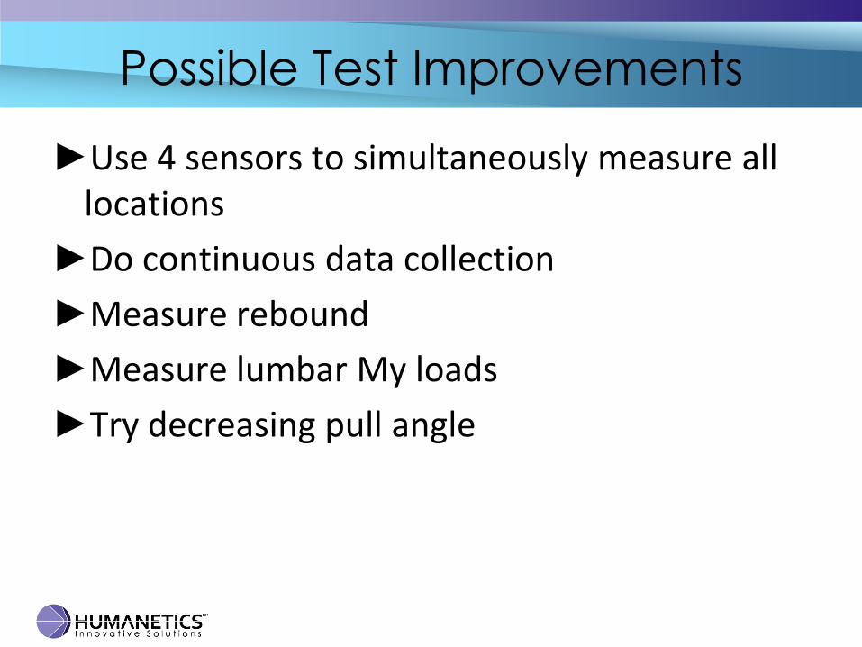
Possible Test Improvements
►Use 4 sensors to simultaneously measure all locations
►Do continuous data collection
►Measure rebound
►Measure lumbar My loads
►Try decreasing pull angle
Related Documents