Optics and Lasers in Engineering 44 (2006) 1–24 Biometric iris recognition system using a fast and robust iris localization and alignment procedure Balaji Ganeshan a, , Dhananjay Theckedath b , Rupert Young a , Chris Chatwin a a Department of Engineering and Design, School of Science and Technology, University of Sussex, Brighton BN1 9QT, UK b Biomedical Engineering Department, D.J. Sanghvi College of Engineering, University of Mumbai, Mumbai-400 056, India Received 4 January 2005; received in revised form 4 March 2005; accepted 22 March 2005 Available online 15 June 2005 Abstract Iris recognition as a biometric technique for personal identification and verification is examined. The motivation for this stems from the observation that the human iris provides a unique structure suitable for non-invasive biometric assessment. In particular the irises are as distinct as fingerprints or patterns of retinal blood vessels and the appearance of the iris is amenable to remote examination. In this paper we have used a database of iris images of more than 100 people, which was used in the implementation of the iris recognition software. The software developed uses a novel technique of localization, alignment, pattern matching of the irises and finally the decision regarding the degree of match. r 2005 Elsevier Ltd. All rights reserved. Keywords: Iris; LoG filter; Laplacian pyramid; Biometrics and pattern recognition 1. Introduction Biometrics deals with the uniqueness of an individual arising from their physiological or behavioral characteristics for the purpose of personal identification. ARTICLE IN PRESS 0143-8166/$ - see front matter r 2005 Elsevier Ltd. All rights reserved. doi:10.1016/j.optlaseng.2005.03.010 Corresponding author. Tel.: +44 1273872642. E-mail address: [email protected] (B. Ganeshan).

Welcome message from author
This document is posted to help you gain knowledge. Please leave a comment to let me know what you think about it! Share it to your friends and learn new things together.
Transcript

ARTICLE IN PRESS
Optics and Lasers in Engineering 44 (2006) 1–24
0143-8166/$ -
doi:10.1016/j
�Correspo
E-mail ad
Biometric iris recognition system using a fast androbust iris localization and alignment procedure
Balaji Ganeshana,�, Dhananjay Theckedathb,Rupert Younga, Chris Chatwina
aDepartment of Engineering and Design, School of Science and Technology, University of Sussex,
Brighton BN1 9QT, UKbBiomedical Engineering Department, D.J. Sanghvi College of Engineering, University of Mumbai,
Mumbai-400 056, India
Received 4 January 2005; received in revised form 4 March 2005; accepted 22 March 2005
Available online 15 June 2005
Abstract
Iris recognition as a biometric technique for personal identification and verification is
examined. The motivation for this stems from the observation that the human iris provides a
unique structure suitable for non-invasive biometric assessment. In particular the irises are as
distinct as fingerprints or patterns of retinal blood vessels and the appearance of the iris is
amenable to remote examination. In this paper we have used a database of iris images of more
than 100 people, which was used in the implementation of the iris recognition software. The
software developed uses a novel technique of localization, alignment, pattern matching of the
irises and finally the decision regarding the degree of match.
r 2005 Elsevier Ltd. All rights reserved.
Keywords: Iris; LoG filter; Laplacian pyramid; Biometrics and pattern recognition
1. Introduction
Biometrics deals with the uniqueness of an individual arising from theirphysiological or behavioral characteristics for the purpose of personal identification.
see front matter r 2005 Elsevier Ltd. All rights reserved.
.optlaseng.2005.03.010
nding author. Tel.: +44 1273872642.
dress: [email protected] (B. Ganeshan).
ARTICLE IN PRESS
B. Ganeshan et al. / Optics and Lasers in Engineering 44 (2006) 1–242
Biometric recognition [1] systems verify a person’s identity by analyzing his/herphysical features or behavior (e.g. face [2], fingerprint, voice, signature, keystrokerhythms).
The human iris contains around 266 visible patterns, which forms the basis ofseveral recognition algorithms [5]. Even on the same person, left and right irises aredifferent. The iris is unique to an individual and is stable with age [6].
This paper has been organized in the following way. The iris recognition system isdivided into three parts: image acquisition, iris localization and pattern matching aregiven in Section 2. In Section 3, the algorithm of this system is explained. In Section4, we discuss the results obtained from this system and the robustness of the system.Finally in Section 5, we make concluding remarks.
2. Iris recognition system
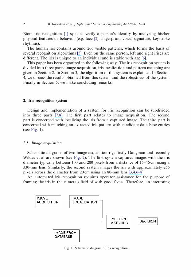
Design and implementation of a system for iris recognition can be subdividedinto three parts [7,8]. The first part relates to image acquisition. The secondpart is concerned with localizing the iris from a captured image. The third part isconcerned with matching an extracted iris pattern with candidate data base entries(see Fig. 1).
2.1. Image acquisition
Schematic diagrams of two image-acquisition rigs firstly Daugman and secondlyWildes et al are shown (see Fig. 2). The first system captures images with the irisdiameter typically between 100 and 200 pixels from a distance of 15–46 cm using a330-mm lens. Similarly, the second system images the iris with approximately 256pixels across the diameter from 20 cm using an 80-mm lens [3,4,6–8].
An automated iris recognition requires operator assistance for the purpose offraming the iris in the camera’s field of with good focus. Therefore, an interesting
Fig. 1. Schematic diagram of iris recognition.

ARTICLE IN PRESS
Fig. 2. Schematic diagrams of Daugman & Wildes et al. image acquisition systems.
B. Ganeshan et al. / Optics and Lasers in Engineering 44 (2006) 1–24 3
method of localization and alignment that automatically frames a subject’s iris withminimal subject participation is employed in this paper.
2.2. Iris localization
Image acquisition of the iris cannot be expected to yield an image containing onlythe iris. It will also contains data derived from the surrounding eye region.Therefore, prior to iris pattern matching, it is important to localize that portion ofthe image derived from inside the limbus (the border between the sclera and the iris)and outside the pupil [4].
If the eyelids are occluding part of the iris, then only that portion of the imagewithout the eyelids should be included.
2.3. Pattern matching
After iris localization, the final step is pattern matching of the iris image with otherimages from the database.

ARTICLE IN PRESS
B. Ganeshan et al. / Optics and Lasers in Engineering 44 (2006) 1–244
3. Algorithm (see Flow Chart 1)

ARTICLE IN PRESS
B. Ganeshan et al. / Optics and Lasers in Engineering 44 (2006) 1–24 5

ARTICLE IN PRESS
B. Ganeshan et al. / Optics and Lasers in Engineering 44 (2006) 1–246
3.1. Localization and alignment of the iris image
First the iris image of the person to be identified is captured and then comparedwith the images existing in the database [9] (see Fig. 3).
Aligning of the localized iris image is the next important step before PatternMatching. Direct comparison of any two images is not possible before obtainingprecise correspondence between the two images. Following are the steps taken inLocalization and Alignment of the Iris Image.
Firstly, a circular contour is formed around the iris to eliminate the remainingportion of the eye [10] (see Fig. 4); a circular pseudo image is formed of desireddiameter. The inside region of the circle is set at gray level ‘1’ and the outside regionto ‘0’. The diameter selected is such that the circular contour will encircle the entireiris. This diameter selection is crucial as it should be common for all iris images. Thuswhen the product of the gray levels of the circular pseudo image and the original irisimage are taken, the resultant image will have the circular contour enclosing the irispatterns and the outside of the circular contour will be at gray level ‘0’. The resultantimage is the localized iris image.
This circular contour is moved such that it is concentric with the pupil. Alignmentis required as often minor shifts occur due to offsets in the position of the eye alongthe camera’s optical axis. So before pattern-matching, alignment is carried out. Thelimbus and pupilary boundary of the iris are concentric about the pupilary center. Soour aim is to determine the pupilary center. Firstly, we use point image processingtechniques such as thresholding and gray-level slicing (without the background) onthe resultant localized image to eliminate every other feature except the pupil of theeye. The pupil of the eye is set at gray level ‘0’ and rest of the region is at ‘255’. The
Fig. 3. Original iris image present in the database.

ARTICLE IN PRESS
B. Ganeshan et al. / Optics and Lasers in Engineering 44 (2006) 1–24 7
next step involves determining the center of the pupil. This is done by finding the rowand column having the maximum number of pixels of gray level ‘0’, whichcorresponds to the center of the pupil. Knowing the center of the pupil, we nowshift the center of the circular contour to the center of the pupil. The resultantimage will have the pupil and the iris regions concentric with the circular contour(see Fig. 5).
Moving the localized iris image to the center of the frame (see Fig. 6) is performednext. The image obtained from the circular contour encircling the pupil and the iris is
Fig. 4. Formation of a circular contour around the iris.
Fig. 5. The circular contour is concentric with the circular pupil.

ARTICLE IN PRESS
B. Ganeshan et al. / Optics and Lasers in Engineering 44 (2006) 1–248
not at the center of the frame. So the final step in the alignment involves shifting thecircular contour to the center of the frame. Knowing the center of the frame and thecenter of the circular contour, the difference in the two centers can be determined.Using this difference, gray level shifting on the image is carried out appropriately.The resultant image will have the center of the circular contour coinciding with thecenter of the frame.
Fig. 7. Localized and aligned iris image.
Fig. 6. Localized iris image is at the center of the frame.

ARTICLE IN PRESS
B. Ganeshan et al. / Optics and Lasers in Engineering 44 (2006) 1–24 9
Removing the portion of the iris occluded by the eyelids (see Fig. 7) is carried outnext. The eyelids are occluding part of the iris, so only that portion of the imagebelow the upper eyelids and above the lower eyelids are included. This is achieved bychanging the gray level above the upper eyelids and below the lower eyelids to ‘0’.Thus the resultant image obtained after localization and alignment can now beanalyzed using pattern-matching techniques.
3.2. Determination of the limbus and the pupil diameter ratio
The ratio of limbus diameter and pupil diameter forms the first criterion in thecomparison of any two irises. The following are the steps to determine the ratio.
First step involves determining the limbus diameter (see Figs. 8–10). Using imagepoint processing operators, mainly gray level slicing with and without thebackground and a digital negative, we obtain only the limbus at gray level ‘0’ andthe remaining portion of the image is at gray level ‘255’. The shape of the limbus inthis case can be considered to be semi-circular.
Now scanning row-wise, a counter determines the number of pixels having graylevel ‘0’ in each row and the maximum count can be considered as the diameter ofthe limbus along the row. Now scanning column-wise, a counter determines thenumber of pixels having gray level ‘0’ in each column and the maximum count can beconsidered as the radius of the limbus. Doubling gives the diameter of the limbusalong the column. Taking the average of the two, we get the average limbusdiameter.
The second step involves determining the pupil diameter (see Fig. 11). Theisolation of the pupil was already achieved in the earlier technique involving
Fig. 8. Selection of the portion of the iris for the determination of the limbus diameter.

ARTICLE IN PRESS
Fig. 9. Intermediate step in the isolation of the limbus.
Fig. 10. Isolation of limbus.
B. Ganeshan et al. / Optics and Lasers in Engineering 44 (2006) 1–2410
alignment. The pupil has a gray level ‘0’ and rest of the region is at ‘255’. Nowscanning row-wise, a counter determines the number of pixels having gray level ‘0’ ineach row and the maximum count can be considered as the diameter of the pupilalong the row. Now scanning column-wise, a counter will count the number of pixelshaving gray level ‘0’ in each column and the maximum count can be considered as

ARTICLE IN PRESS
Fig. 11. Isolation of the pupil from the rest of the iris image.
B. Ganeshan et al. / Optics and Lasers in Engineering 44 (2006) 1–24 11
the diameter of the pupil along the column. Taking the average of the two, we obtainthe average pupil diameter.
Finally, the ratio of the limbus diameter and the pupil diameter is determinedwhich is an important criterion in the identification/comparison of the irises.
3.3. Pattern matching
After localizing and aligning the image containing the iris, the next task is todecide if this pattern matches with the one existing in the database. The patternmatching is decomposed into three parts.
Firstly a representation of the localized and aligned iris image is chosen that makestheir distinctive patterns apparent. In this paper we employ an isotropic, circularlysymmetric [11] band-pass decomposition derived from the application of Laplacianof Gaussian filter to the image. This results in a pyramid formation of the iris imagei.e. a Multiscale Representation which is used for iris pattern matching realized bythe filter (see Fig. 12).
The characteristics of the human iris are manifest at a variety of scales,distinguishing structures ranging from the overall shape of the iris. The main idea ofusing a multi-scale representation in this paper is to capture this range of spatialdetail to detect and characterise edges of the numerous iris patterns known. As thename suggests, a multi-scale representation gives us iris images at varying spatialscales. It is observed that different structures give rise to edges at varying scales;small scales correspond to fine details and large scales correspond to gross structures.By studying the image at each scale, classification of prominent edges of the differentiris patterns at each level is possible. In this paper multi-scale representation isachieved using the pyramid algorithm of Laplacian of Gaussian filters (4 levels)

ARTICLE IN PRESS
Fig. 12. Multiscale representations for iris pattern matching.
B. Ganeshan et al. / Optics and Lasers in Engineering 44 (2006) 1–2412
employing down sampling in the Gaussian and up sampling in the Laplacian of theGaussian, filtered image. Besides being capable of making finer grained distinctionsbetween different irises, this technique is of note for efficient storage and processing,as lower frequency bands are sub-sampled successively without loss of informationbeyond that introduced by the filtering.
3.4. Steps involved in the multiscale representation using LoG filter
The LoG filter [4] can be specified as
�1�ps4
� �ð1 � r2=2s2Þe�r2=2s2
, (1)
where s—standard deviation of the Gaussian, r—radial distance of a point from thefilter’s center.
A discrete approximation which is derived from the above filter expression.One dimensional mask w ¼ ½1 4 6 4 1�=16, Two dimensional mask W ¼ wT x w,
wT—transpose of the 1–D mask w.
The resultant 5 � 5 matrix mask
W ¼ 1=256
1 4 6 4 1
4 16 24 16 4
6 24 36 24 6
4 16 24 16 4
1 4 6 4 1
��������������
��������������.

ARTICLE IN PRESS
Fig. 13. Low-pass Gaussian images.
B. Ganeshan et al. / Optics and Lasers in Engineering 44 (2006) 1–24 13
Now construction of the Laplacian Pyramid begins first with convolution of theIris Image with LoG Mask ‘W’, so as to yield low-pass Gaussian filtered images gk
(see Fig. 13). The expression is as follows:
gk ¼ ðW � gk�1Þ#2, (2)
where k varies from 1 to 4, g0—iris image of original scale, g1–g4—low-passGaussian images each obtained after filtering the previous image and down samplingby 2, ð:Þ#2—down sampling by a factor of two in each image dimension.
Now after construction of low-pass Gaussian images at 4 different scales, theLaplacian pyramid lk is formed as the difference between gk and gkþ1, with gkþ1
expanded before subtraction so that it matches the sampling rate of gk. Theexpansion is accompanied by up sampling and interpolation:
lk ¼ gk � 4W � ðgkþ1Þ"2, (3)
where ð:Þ"2 indicates up sampling by a factor of 2.Up sampling is achieved by the insertion of zeros between each row and column of
the down sampled Gaussian image. The Mask ‘W’ is used as an interpolation filterand the factor 4 is necessary because 3
4pixels are newly inserted zeros. The difference
of Gaussians that this representation entails yields a good approximation toLaplacian of Gaussian filtering (see Fig. 14).

ARTICLE IN PRESS
Fig. 14. Spatial decomposed multiscale Laplacian of Gaussian images.
B. Ganeshan et al. / Optics and Lasers in Engineering 44 (2006) 1–2414
We then evaluate the degree of match between the acquired image and imagesfrom the database. The approach taken is to quantify for the degree of match usingnormalized correlation between the acquired image and the images from thedatabase. Normalized correlation can be defined in discrete form as follows:
Let lk1½i; j� and lk2
½i; j� be the two iris images of size r � c (rows� columns).Let
m1 ¼ ð1=ðr � cÞÞXr
i¼1
Xc
j¼1
lk1½i; j�; (4)
s1 ¼
ffiffiffiffiffiffiffiffiffiffiffiffiffiffiffiffiffiffiffiffiffiffiffiffiffiffiffiffiffiffiffiffiffiffiffiffiffiffiffiffiffiffiffiffiffiffiffiffiffiffiffiffiffiffiffiffiffiffiffiffiffiffiffiffiffiffiffiffiffiffiffið1=ðr � cÞÞ
Xr
i¼1
Xc
j¼1
ðlk1½i; j� � m1Þ
2
" #vuut , (5)
where m1 and s1 are the mean and standard deviation for the intensities of lp1,respectively.
Let
m2 ¼ ð1=ðr � cÞÞXr
i¼1
Xc
j¼1
lk2½i; j�; (6)
s2 ¼
ffiffiffiffiffiffiffiffiffiffiffiffiffiffiffiffiffiffiffiffiffiffiffiffiffiffiffiffiffiffiffiffiffiffiffiffiffiffiffiffiffiffiffiffiffiffiffiffiffiffiffiffiffiffiffiffiffiffiffiffiffiffiffiffiffiffiffiffiffiffiffið1=ðr � cÞÞ
Xr
i¼1
Xc
j¼1
ðlk2½i; j� � m2Þ
2
" #vuut , (7)

ARTICLE IN PRESS
B. Ganeshan et al. / Optics and Lasers in Engineering 44 (2006) 1–24 15
where m2 and s2 are the mean and standard deviation for the intensities oflp2, respectively.
Normalized correlation between lk1and lk2
can be defined asPri¼1
Pcj¼1ðlk1
½i; j� � m1Þðlk2½i; j� � m2Þ
r � c � s1 � s2. (8)
Normalized correlation is preferred over standard correlation, since normalizedcorrelation accounts for local variations in image intensity that disrupts standardcorrelation. This robustness is achieved since the mean intensities are subtracted inthe numerator and the standard deviations are multiplied in the denominator of thecorrelation ratio. The matching operation results in multiple correlation values foreach of the four spatial frequency bands. Thus the matching multiscale representa-tion using normalized correlation yields a set of four goodness-of-match values, onefor each frequency band. Blocking of non-relevant image data, combined with amedian operation allows for local adjustments of matching and a degree of outlierrejection thereby providing robustness against mismatches due to noise, misalign-ment and occlusion of stray eyelashes.
Finally we decide whether the acquired image and image from the database arederived from the same iris, based on the degree of match. The decision-makingprocesses are based on the four goodness-of-match correlation measurementscalculated by the previous stage of processing (one for each band of frequency inthe Laplacian pyramid representation). The normalized correlation coefficientobtained for the first Laplacian of Gaussian of both the images is the most reliablevalue for comparison, as it highlights generally all the edges of the iris patterns (grossfeatures). The spatial scale of the second, third and the fourth Laplacian of Gaussianimage reduces by half compared to the previous image. The effect of multi-scalingtechnique [4] and application of the LoG filter reduces enhancement of gross featuresof the iris, leaving very few details of the iris in the sub-scaled images. This causescorrelation coefficient values between images to increase with the reduction in thespatial scale. The correlation coefficient values vary from 0.5 to 0.9; the least value isobtained for the first Laplacian of Gaussian comparison and the highest value for thefourth Laplacian of Gaussian comparison. A correlation coefficient value of oneindicates a perfect match between the acquired image and the image from the database.
4. Results
The results obtained for the iris images of two different persons, of the sameperson and of the same person which are identical in all aspects except that threedots are incorporated in the iris region of one image using the above mentionedrecognition system are summarized in the tables (see Tables 1–3). The two iris imagesused for illustrating the result of the system along with the various intermediate stepsof image processing of the two images are shown (see Figs. 15–24). The iris images ofthe same person in which one image has three dots incorporated in the iris region areshown (see Figs. 25 and 26).

ARTICLE IN PRESS
Table 2
Result obtained from this iris recognition system for iris images of same person
Ratio of Limbus Diameter & Pupil Diameter of both the irises are equal (Figs. 17, 19)
Corr0 ¼ 1.0000—Normalized correlation value for the 1st Laplacian of Gaussian of the 2 iris images (Fig.
23)
Corr0 ¼ 1.0000—Normalized correlation value for the 2nd Laplacian of Gaussian of the 2 iris images
(Fig. 23)
Corr0 ¼ 1.0000—Normalized correlation value for the 3rd Laplacian of Gaussian of the 2 iris images (Fig.
23)
Corr0 ¼ 1.0000—Normalized correlation value for the 4th Laplacian of Gaussian of the 2 iris images (Fig.
23)
Both the irises are identical
Table 1
Result obtained from this iris recognition system for iris images of two different persons
Ratio of Limbus Diameter & Pupil Diameter of both the irises are not equal (Figs. 17–20)
Corr0 ¼ 0.6625—Normalized correlation value for the 1st Laplacian of Gaussian of the 2 iris images
(Figs. 23 and 24)
Corr0 ¼ 0.8101—Normalized correlation value for the 2nd Laplacian of Gaussian of the 2 iris images
(Figs. 23 and 24)
Corr0 ¼ 0.8513—Normalized correlation value for the 3rd Laplacian of Gaussian of the 2 iris images
(Figs. 23 and 24)
Corr0 ¼ 0.9284—Normalized correlation value for the 4th Laplacian of Gaussian of the 2 iris images
(Figs. 23 and 24)
Both the irises are not identical
Table 3
Result obtained from this iris recognition system for iris image of a person with the iris image of the same
person but modified by incorporating 3 dots in the iris region
Ratio of Limbus Diameter & Pupil Diameter of both the irises are equal (Figs. 25 and 26)
Corr0 ¼ 0.9953—Normalized correlation value for the 1st Laplacian of Gaussian of the 2 iris images
(Figs. 25 and 26)
Corr0 ¼ 0.9990—Normalized correlation value for the 2nd Laplacian of Gaussian of the 2 iris images
(Figs. 25 and 26)
Corr0 ¼ 0.9988—Normalized correlation value for the 3rd Laplacian of Gaussian of the 2 iris images
(Figs. 25 and 26)
Corr0 ¼ 0.9998—Normalized correlation value for the 4th Laplacian of Gaussian of the 2 iris images
(Figs. 25 and 26)
Both the irises are not identical
B. Ganeshan et al. / Optics and Lasers in Engineering 44 (2006) 1–2416
4.1. Robustness of the designed iris recognition software
The software [12] for iris recognition developed in this paper covers a sequence ofoperations. The first is localization and alignment of the iris image prior tocorrelation of the two images. The next intermediate step in iris identification isdetermination of the ratio of limbus diameter to pupil diameter for both irises. If the

ARTICLE IN PRESS
Fig. 15. Original iris image of person A.
Fig. 16. Original iris image of person B.
B. Ganeshan et al. / Optics and Lasers in Engineering 44 (2006) 1–24 17
two ratios match, the next step is to determine of the correlation, otherwise the twoirises are not identical and further processing time in calculating the correlation canbe saved.

ARTICLE IN PRESS
Fig. 17. Steps in localization and alignment iris image A.
Fig. 18. Steps in localization and alignment iris image B.
B. Ganeshan et al. / Optics and Lasers in Engineering 44 (2006) 1–2418

ARTICLE IN PRESS
Fig. 19. Localized and aligned iris image A.
Fig. 20. Localized and aligned iris image B.
B. Ganeshan et al. / Optics and Lasers in Engineering 44 (2006) 1–24 19

ARTICLE IN PRESS
Fig. 21. Gaussian low-pass of iris image A.
B. Ganeshan et al. / Optics and Lasers in Engineering 44 (2006) 1–2420
The next step is pattern matching using the normalized correlation technique.Each image from the Laplacian Pyramid formed from the LoG filtered images givesimportant information on the different iris patterns prominent at different scales.Thus the correlation between the images of the irises and templates at each level ofthe pyramid effectively gives the degree-of-match for the specific iris patternsprominent at that scale.
The normalized correlation employed in this paper gives a very accurate resultas it accounts for local variations in image intensity that corrupts standardcorrelation. For this reason decision-making is made simpler and the robustnessof the system also increases. This is illustrated as follows. The normalized correla-tion for the two iris images (see Figs. 25 and 26) is determined. Both the irisesare identical in all aspects except that in the modified image three dots havebeen deliberately introduced into the iris region. The normalized correlation ofthe two iris images for the first Laplacian is 0.9953, showing the sensitivity ofthe normalized correlation technique for detecting very small perturbations inthe image.
The criteria used during the development of this software makes this irisrecognition technique highly robust.

ARTICLE IN PRESS
Fig. 22. Gaussian low-pass of iris image B.
Fig. 23. Laplacian of Gaussian of iris image A.
B. Ganeshan et al. / Optics and Lasers in Engineering 44 (2006) 1–24 21

ARTICLE IN PRESS
Fig. 24. Laplacian of Gaussian of iris image B.
Fig. 25. Original iris image.
B. Ganeshan et al. / Optics and Lasers in Engineering 44 (2006) 1–2422
5. Conclusion
Iris recognition is fast developing to be a foolproof and fast identificationtechnique that can be administered cost effectively. It is a classic biometricsapplication that is in an advanced stage of research all over the world.

ARTICLE IN PRESS
Fig. 26. Modified image with three black dots.
B. Ganeshan et al. / Optics and Lasers in Engineering 44 (2006) 1–24 23
The automated localization and alignment technique used in this paper is quiteunique and efficiently frames the subject’s iris with minimum subject participation.The systems considers the ratio of limbus to pupil diameter as the initial criterion forrecognition, which saves the processing time involved in pattern matching andcalculating the correlation when the two ratios are not equal.
The pattern matching technique employs multiscale pyramid representation usinga LoG filter, which provides optimal enhancement of the features of the iris patterns,and then normalized correlation is employed for evaluating the degree of similarityand has been shown to give accurate results.
Acknowledgement
Balaji Ganeshan thankfully acknowledges the Iris Recognition Research GroupNational Laboratory of Pattern Recognition (NLPR) Institute of Automation,Chinese Academy of Sciences for sharing their database of iris images.
References
[1] Jain AK, Ross A, Prabhakar S. An introduction to biometric recognition. IEEE transactions on
circuits and systems for video technology—special issue on image and video-based biometrics, vol.
14(1); 2004.
[2] Kashima H, Hongo H, Kato K, Yamamoto K. A robust iris detection method of facial and eye
movement. Canadian conference on computer and robot vision (CRV); 2001.
[3] Daugman JG. The importance of being random: statistical principles of iris recognition. J Pattern
Recognition Soc 2001;PR1656:1–13.

ARTICLE IN PRESS
B. Ganeshan et al. / Optics and Lasers in Engineering 44 (2006) 1–2424
[4] Wildes RP. Iris recognition: an emerging biometric technology. Proceedings of the IEEE, vol. 85(9);
1997. p. 1348–63.
[5] Zhu Y, Tan T, Wang Y. Biometric personal identification based on iris patterns. Proceedings of
IAPR, international conference on pattern recognition (ICPR’2000), vol. II; 2000. p. 805–8.
[6] Daugman JG, Downing C. Epigenetic randomness, complexity and singularity of human iris patterns
Proceedings of the Royal Society, Biological Sciences, vol. 268; 2001. p. 1737–40.
[7] Daugman J G. How iris recognition works. IEEE Trans CSVT 2004;14(1):21–30.
[8] Daugman JG. High confidence visual recognition of persons by a test of statistical independence.
IEEE Trans PAMI 1993;15(11):1148–61.
[9] Iris Image Database—Iris Recognition Research Group National Laboratory of Pattern Recognition
(NLPR) Institute of Automation. Chinese Academy of Sciences; http://www.sinobiometrics.com.
[10] Gonzalez RC, Woods RE. Digital image processing, 2nd ed. Singapore: Pearson Education Pvt. Ltd.;
2003.
[11] Ma L, Wang Y, Tan T. Iris recognition using circular symmetric filters. 16th international conference
on pattern recognition (ICPR), vol. II; 2002.
[12] Chapman SJ. MATLAB programming for engineers, 2nd ed. Singapore: Thomson Asia Pvt. Ltd.;
2002.
Related Documents