© 2013 WILEY-VCH Verlag GmbH & Co. KGaA, Weinheim 2344 www.advmat.de www.MaterialsViews.com wileyonlinelibrary.com COMMUNICATION Ling Li and Christine Ortiz* Biological Design for Simultaneous Optical Transparency and Mechanical Robustness in the Shell of Placuna placenta L. Li, Prof. C. Ortiz Room 13-4022, Department of Materials Science and Engineering Massachusetts Institute of Technology MA 02139, USA E-mail: [email protected] DOI: 10.1002/adma.201204589 The phenotype of biological systems can be represented by a space of traits, for example, macroscopic morphology, physi- ology, behavior, and, more recently, material properties, which are governed by natural selection through the adaptations to species-specific habitats in order to achieve multiple func- tions. [1–3] Biological exoskeletons, for example, need to simul- taneously satisfy requirements of protection from predators, hydration and thermal regulation, locomotion, reproduction and etc. Such systems exhibit a hierarchical (length-scale dependent) set of structural features including molecular structure, chem- ical composition, and spatial distribution and crystallographic orientation of building blocks, which are coupled to larger length-scale morphology in order to achieve desired mechan- ical, optical, thermal, and other relevant properties. [4–6] A signif- icant amount of research has focused on the structural origins of the unusual combination of superior mechanical properties of a variety of biological exoskeletal systems. [6–10] Recently, a number of mollusk species have been shown to possess shells that exhibit both mechanical and optical functions, including selective light diffusion, photonic coloration, and vision. [11–14] Here, through a combination of experimental and theoretical methods, we investigate a highly mineralized biological exo- skeleton of Placuna placenta, which simultaneously achieves high optical transparency and mechanical robustness. While it is unclear whether or not the transparency plays a biological role, the design leading to a combination of these characteris- tics in a single system holds great potential for the development of bio-inspired engineering transparent structural materials for both commercial and military applications, including, for example, soldier eye/face protection, windows and windshields, blast shields, and combat vehicle vision blocks. [15,16] The natural transparent structural material system from Pla- cuna placenta (Linnaeus, 1758; Mollusca: Bivalvia; commonly known as window pane oyster) has two highly transparent, circular-shaped flat mineralized valves ( Figure 1). P. pla- centa lives unattached on the surfaces of muddy or sandy flats in shallow water (depth < 100 m) of the tropical Indo-West Pacific. [17] Due to the high optical transparency of their shells, P. placenta are widely collected and commercially cultured in large quantities for shellcrafts, and local people are known to use the shells as a substitute for window glass in houses. [17] The entire shell is highly transparent except the posterior adductor scar (PAS) regions (the whitish regions indicated by the red circles, Figure 1B), which are used for adductor muscle attachment. Scanning electron microscopy (SEM) of cryo-fractured sur- faces showed that the P. placenta shell is composed of a min- eralized lamellar microstructure ( Figure 2A) with a crystal- lographic phase of calcite (as shown later). Top-viewed SEM images of freshly cleaved samples reveal the mosaic-like organi- zation of the elongated diamond-shaped building blocks, which have arrow-point endings and coalesce laterally to form laminae or sheets (Figure 2B). This is the primary feature of the foli- ated microstructure commonly observed in bivalves and some limpets. [18,19] The characteristic length, width, and tip angle of the building blocks as defined in Figure 2B are 141.8 ± 43.4 μm (mean ± standard deviation, n = 40), 5.54 ± 1.36 μm (n = 49), and 10.45 ± 2.95 ° (n = 71), respectively. With the excep- tion of the PAS regions, where a thin layer ( ∼20 μm) of a pris- matic microstructure is present on the inner side of the shell, the entire shell is composed of the foliated microstructure, as both top and bottom shell surfaces exhibit similar elongated building blocks (Figure S1-2). This single-microstructure design is con- sistent with Taylor’s hypothesis of the microstructural evolution trends in bivalves, where the outer prismatic layer is completely absent in Pectinacea, Limacea, and Anomiacea. [20] Addition- ally, unlike most other bivalves, no organic periostracum layer was found on the exterior side of the P. placenta shell. Detailed mapping of the entire cross-section of the shell reveals a rela- tively constant thickness profile of the foliated structure (294 ± 84 nm, n = 1748), although a slight decrease to ∼50 nm towards the PAS prismatic/foliated interface was observed (Figure S3). Tapping mode atomic force microscopy (TMAFM) analysis of Figure 1. Highly transparent shells of P. placenta. A) Live P. placenta in their natural habitat (Changi Beach, Singapore, August 2011). Green seaweed behind the shells can be seen (red arrow). Photo was used with permission from Ria Tan. B) P. placenta shell specimens with edges trimmed. “PAS” = posterior adductor scar (red circles). White arrow indi- cates the growth lines. C) Square-shaped tiles cut from P. placenta shell specimens. Adv. Mater. 2013, 25, 2344–2350

Welcome message from author
This document is posted to help you gain knowledge. Please leave a comment to let me know what you think about it! Share it to your friends and learn new things together.
Transcript
2344
www.advmat.dewww.MaterialsViews.com
CO
MM
UN
ICATI
ON
Ling Li and Christine Ortiz *
Biological Design for Simultaneous Optical Transparency and Mechanical Robustness in the Shell of Placuna placenta
Figure 1 . Highly transparent shells of P. placenta . A) Live P. placenta in their natural habitat (Changi Beach, Singapore, August 2011). Green seaweed behind the shells can be seen (red arrow). Photo was used with permission from Ria Tan. B) P. placenta shell specimens with edges trimmed. “PAS” = posterior adductor scar (red circles). White arrow indi-cates the growth lines. C) Square-shaped tiles cut from P. placenta shell specimens.
The phenotype of biological systems can be represented by a space of traits, for example, macroscopic morphology, physi-ology, behavior, and, more recently, material properties, which are governed by natural selection through the adaptations to species-specifi c habitats in order to achieve multiple func-tions. [ 1–3 ] Biological exoskeletons, for example, need to simul-taneously satisfy requirements of protection from predators, hydration and thermal regulation, locomotion, reproduction and etc. Such systems exhibit a hierarchical (length-scale dependent) set of structural features including molecular structure, chem-ical composition, and spatial distribution and crystallographic orientation of building blocks, which are coupled to larger length-scale morphology in order to achieve desired mechan-ical, optical, thermal, and other relevant properties. [ 4–6 ] A signif-icant amount of research has focused on the structural origins of the unusual combination of superior mechanical properties of a variety of biological exoskeletal systems. [ 6–10 ] Recently, a number of mollusk species have been shown to possess shells that exhibit both mechanical and optical functions, including selective light diffusion, photonic coloration, and vision. [ 11–14 ] Here, through a combination of experimental and theoretical methods, we investigate a highly mineralized biological exo-skeleton of Placuna placenta , which simultaneously achieves high optical transparency and mechanical robustness. While it is unclear whether or not the transparency plays a biological role, the design leading to a combination of these characteris-tics in a single system holds great potential for the development of bio-inspired engineering transparent structural materials for both commercial and military applications, including, for example, soldier eye/face protection, windows and windshields, blast shields, and combat vehicle vision blocks. [ 15 , 16 ]
The natural transparent structural material system from Pla-cuna placenta (Linnaeus, 1758; Mollusca: Bivalvia; commonly known as window pane oyster) has two highly transparent, circular-shaped fl at mineralized valves ( Figure 1 ). P. pla-centa lives unattached on the surfaces of muddy or sandy fl ats in shallow water (depth < 100 m) of the tropical Indo-West Pacifi c. [ 17 ] Due to the high optical transparency of their shells,
© 2013 WILEY-VCH Verlag Gwileyonlinelibrary.com
L. Li, Prof. C. Ortiz Room 13-4022, Department of Materials Science and Engineering Massachusetts Institute of Technology MA 02139, USA E-mail: [email protected]
DOI: 10.1002/adma.201204589
P. placenta are widely collected and commercially cultured in large quantities for shellcrafts, and local people are known to use the shells as a substitute for window glass in houses. [ 17 ] The entire shell is highly transparent except the posterior adductor scar (PAS) regions (the whitish regions indicated by the red circles, Figure 1 B), which are used for adductor muscle attachment.
Scanning electron microscopy (SEM) of cryo-fractured sur-faces showed that the P. placenta shell is composed of a min-eralized lamellar microstructure ( Figure 2 A) with a crystal-lographic phase of calcite (as shown later). Top-viewed SEM images of freshly cleaved samples reveal the mosaic-like organi-zation of the elongated diamond-shaped building blocks, which have arrow-point endings and coalesce laterally to form laminae or sheets (Figure 2 B). This is the primary feature of the foli-ated microstructure commonly observed in bivalves and some limpets. [ 18 , 19 ] The characteristic length, width, and tip angle of the building blocks as defi ned in Figure 2 B are 141.8 ± 43.4 μ m (mean ± standard deviation, n = 40), 5.54 ± 1.36 μ m (n = 49), and 10.45 ± 2.95 ° (n = 71), respectively. With the excep-tion of the PAS regions, where a thin layer ( ∼ 20 μ m) of a pris-matic microstructure is present on the inner side of the shell, the entire shell is composed of the foliated microstructure, as both top and bottom shell surfaces exhibit similar elongated building blocks (Figure S1-2). This single-microstructure design is con-sistent with Taylor’s hypothesis of the microstructural evolution trends in bivalves, where the outer prismatic layer is completely absent in Pectinacea, Limacea, and Anomiacea. [ 20 ] Addition-ally, unlike most other bivalves, no organic periostracum layer was found on the exterior side of the P. placenta shell. Detailed mapping of the entire cross-section of the shell reveals a rela-tively constant thickness profi le of the foliated structure (294 ± 84 nm, n = 1748), although a slight decrease to ∼ 50 nm towards the PAS prismatic/foliated interface was observed (Figure S3). Tapping mode atomic force microscopy (TMAFM) analysis of
mbH & Co. KGaA, Weinheim Adv. Mater. 2013, 25, 2344–2350

www.advmat.dewww.MaterialsViews.com
CO
MM
UN
ICATIO
N
Figure 2 . Multiscale structural characteristics of P. placenta shell. A) Scanning electron microscopy (SEM) image of a cyro-fractured surface, showing the laminate structure. B) A top-viewed SEM image of a freshly cleaved shell surface, revealing the elongated diamond-shaped building blocks of the foliated microstructure. Geometrical parameters, i.e., length, width, and tip angle, are defi ned as indicated in the image. C) Tapping-mode atomic force microscopy (AFM) height image of the surface tomography of foliated microstructure, demonstrating the microridges of the building blocks. D) Cross-sectional transmission electron microscopy (TEM) images of the foliated microstructure. Inset, high-resolution TEM image revealing the ultra-thin organic interfaces ( ∼ 2 nm) between two adjacent mineral layers (marked by dotted lines). The lattice fringes match with {104} planes of calcite. E) A top-viewed TEM image of the intracrystalline nanoscopic inclusions within the mineralized building blocks. “N” = normal direction of shell.
freshly cleaved building block interfaces reveals a subtle surface tomographic feature: microridges with inclination angles of 1.4 ± 0.4 ° (Figure 2 C and Figure S4), which may enhance the shell’s mechanical strength and toughness by restricting the sliding of building blocks upon deformation. [ 21 ]
Biological materials are usually composites consisting of biopolymers and minerals. [ 5 ] Thermogravimetric analysis shows that the P. placenta shell is highly mineralized; its mineral con-tent is 98.90 ± 0.19 wt% (n = 3, Figure S5), which is higher than gastropod nacre, coral skeleton, and chiton plates. [ 22 , 23 ] Cross-sectional examination of the foliated microstructure via transmission electron microscopy (TEM) revealed an ultra-thin organic interface ( ∼ 2 nm) between adjacent mineral layers (Figure 2 D and inset), which was also observed by multimode AFM imaging of freshly cleaved surfaces (Figure S6). In addi-tion to intercrystalline organic interfaces sandwiched between mineralized building blocks, nanoscopic intracrystalline inclu-sions are distributed within them (Figure 2 E). These inclu-sions are believed to consist of organic macromolecules trapped during the biomineralization process, which is a common phenomenon observed in a variety of biogenic minerals, including nacre and sea urchin teeth and spines. [ 24–27 ] Through a quantitative dimension analysis using stereological correction methods, [ 28 , 29 ] we determined the average diameter and total volume fraction of the intracrystalline inclusions to be 25.2 nm and 0.45%, respectively (Figure S7).
Determining the crystallographic organization of the calcitic building blocks is critical in order to understand the optical
© 2013 WILEY-VCH Verlag Adv. Mater. 2013, 25, 2344–2350
and mechanical performance of the shell due to the inherent anisotropic optical [ 30 ] and mechanical [ 31 ] properties of calcium carbonate. X-ray diffraction measurements of P. placenta shells show characteristic peaks corresponding to calcite (Figure S8). Crystallographic orientation and distribution at the building block level were studied using electron backscattered diffrac-tion (EBSD) ( Figure 3 ). Figure 3 A displays an SEM image of an area in a freshly cleaved P. placenta shell which was mapped with EBSD. The similar green color in the corresponding Euler angle mapping in Figure 3 B indicates that there is a strong crys-tallographic coorientation among the calcitic building blocks (referenced to the hexagonal unit cell of calcite, a = 4.99 Å, c = 17.06 Å). The corresponding pole fi gures with well-defi ned diffraction spots further demonstrate the alignment (Figure 3 C). The distribution of tilting angles of the calcite c -axes with respect to the shell normal extracted from the {001} pole fi gure is 24.43 ± 3.46 ° (Figure 3 D). A similar result has been reported previously, [ 18 ] and the top surface of the calcitic building blocks is close to {108} planes of calcite (the interplanar angle between {108} and {001} planes is 26.27 ° ). In addition, the tilting direc-tion is towards the longitudinal direction of the building blocks, which is evident by the horizontal shift of {001} diffraction spot in its pole fi gure, consistent with the longitudinal direc-tion of the building blocks in Figure 3 A. The variation in c -axis tilting angles is mainly due to the crystallographic misalign-ment among different building blocks, as shown by the high misorientation angles (typically > 5 ° ) in the misorientation profi le along the transverse direction of the building blocks
2345wileyonlinelibrary.comGmbH & Co. KGaA, Weinheim

2
www.advmat.de
CO
MM
UN
ICATI
ON
Figure 3 . Crystallographic organization of the foliated microstructure in P. placenta at building block level. A) An SEM image of the freshly cleaved shell surface mapped with electron back-scattered diffraction (EBSD). The white arrow indicates the longitudinal direction of the elon-gated building blocks. B) A corresponding EBSD map with color coded for all the three Euler angles ( φ 1, φ , φ 2). The red and blue lines (perpendicular and parallel to the longitudinal direc-tion of building blocks) are indicated for plotting the misorientation profi les along them as shown in E). C) Pole density plots for the mapped region in A). D) Distribution of tilt angle of the calcite c -axis with respect to the shell normal direction. The red curve represents a fi t to a normal distribution to the data. E) Crystallographic misorientation profi les along the transverse (red line) and longitudinal (blue line) directions of the building blocks as shown in B). F) TEM image showing two adjacent intact building blocks. The longitudinal directions of the building blocks are indicated by the white arrows. G-H) Selected area electron diffraction (SAED) pat-terns corresponding to area 1 and 2 in F). Zone axis = [ 11̄1̄ ].
(Figure 3 E). In contrast, the profi le along the longitudinal direc-tion generally exhibits small misorientation angles (typically < 1 ° ) due to its lower probability of crossing the boundaries of building blocks as compared to the transverse direction. The misalignment among adjacent building blocks was further
346 wileyonlinelibrary.com © 2013 WILEY-VCH Verlag GmbH & Co. KGaA, Wein
www.MaterialsViews.com
studied using selected area electron diffrac-tion (SAED) in TEM (Figure 3 F–H). Dif-fraction patterns from two adjacent intact building blocks were indexed with calcite with the zone axis of [ 11̄1̄ ]. The {110} dif-fraction spots are perpendicular to the cor-responding longitudinal direction of the building blocks, which indicates that the c -axis is tilted in this direction, consistent with the EBSD results. The exact tilting angle cannot be determined in this case since the angle between the top surface of the sample and the electron beam might not be exactly perpendicular. Moreover, the rotation angle between the two diffraction patterns for these two adjacent building blocks (6.9 ° ) is con-sistent with the angle between their longitu-dinal axes ( ∼ 6.0 ° ).
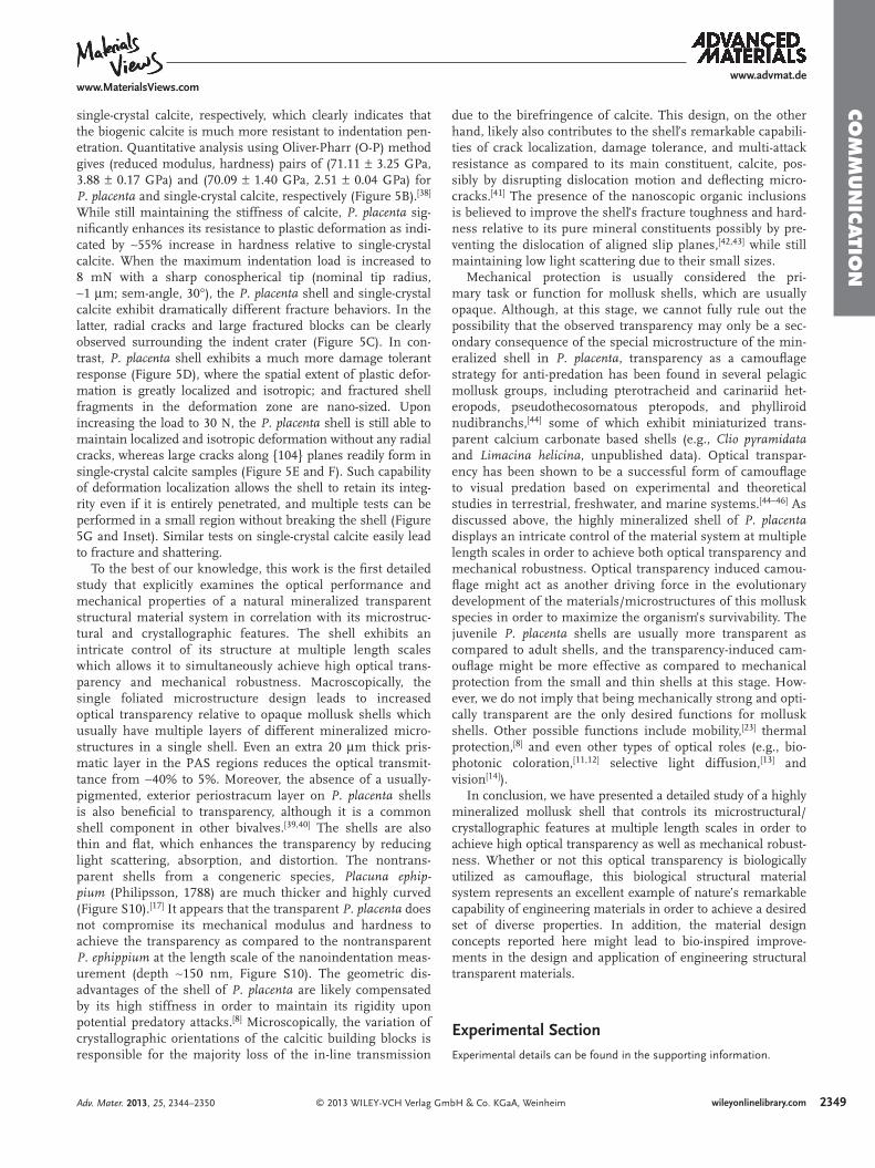
We next performed a systematic investiga-tion of the optical properties of P. placenta shells using both experimental and theoret-ical approaches ( Figure 4 ). The macroscopic in-line transmissions (illumination area, ∼ 1 mm 2 , collection cone, ∼ 2 ° ) were measured via a double-beam spectrophotometer using wavelengths between 250–800 nm. The total forward transmission was also meas-ured with the spectrophotometer by equip-ping it with an integration sphere. Typical transmission and refl ection spectra of the shells (thickness ∼ 0.5 mm) are presented in Figure 4 A. The shell exhibits high total transmission in the visible light range (up to ∼ 80%), and summation of total transmission and refl ection leads to ∼ 95% of the incident light intensity, indicating this biocomposite absorbs a very small amount of visible light. The typical in-line transmission is about one half of the total transmission, and the posi-tive correlation between the intensity and wavelength suggests the possible presence of light scattering. Interestingly, the in-line transmission intensity for the PAS area is very low ( < 5%) in comparison to the majority of the shell, which suggests that the single macroscopic layer with the same microstruc-ture (foliated in this case) is benefi cial for high optical transmittance. The microscopic optical performance of P. placenta shell was determined using a microspectrometer, through which the local transmission and refl ection of samples was collected confocally via one of the microscope ports and guided through an optical fi ber to a spectrometer
(typical step size: 1 μ m). The shell exhibits homogeneous trans-mission ( ∼ 85%) and refl ection ( ∼ 13%) at the building block level (Figure 4 B and Figure S9).
The optical performance of P. placenta shells was inves-tigated theoretically by modeling the light scattering which
heim Adv. Mater. 2013, 25, 2344–2350

www.advmat.dewww.MaterialsViews.com
CO
MM
UN
ICATIO
N
Figure 4 . Optical properties of P. placenta shell. A) Macroscopic optical performance of the as-received P. placenta shell with thickness of ∼ 0.5 mm. B) Microscopic optical mappings at wavelength of 600 nm for transmission (middle) and refl ection (right) measured in the area of sample (thickness, ∼ 100 μ m) shown in the optical refl ection image (left). The maps were generated from arrays of 50 × 50 individual spectrum measurements with a step size of 1 μ m using a microspectrometer. C) Predictions based on the light scattering model (dotted) and measurement (solid) of the in-line transmission intensities as a function of wavelength for samples with different thicknesses. D) Scattering coeffi cients of inclusion scattering (black), birefringence scattering (red), and total scattering (blue) as calculated from Equation 2 , 3 , and 4 . E) Experimentally measured size distribution of the intracrystalline inclusions after stereological correction (black line), and the scattering effi ciency factor for wavelengths of 400, 500, 600 and 700 nm as a function of inclusion sizes.
results from a combination of mechanisms. [ 32 , 33 ] Firstly, the in-line transmission ( T , [-]) can be expressed by the Lambert-Beer Law:
T = (1 − R) exp(−Cscat) (1)
where R is the refl ection [–], C csa [m − 1 ] is the effective scattering coeffi cient, and t [m] is the sample thickness.
Nanoscopic intracrystalline inclusions contribute to the light scattering, as the refractive index of organic inclusions and sur-rounding mineral matrix have different refractive indices. Addi-tionally, calcite is a highly birefringent material, which means the refractive indices vary with the crystal orientations. [ 30 ] The misorientation of the calcitic building blocks leads to a discon-tinuity of the refractive indices, which further causes scattering of incident light. Thus the effective scattering coeffi cient is the sum of the scattering caused by the inclusions and by the birefringence:
Csca = Cincl + Cbir e (2)
The scattering coeffi cient for the inclusions ( C incl ) can be expressed as follows
Cincl = Nincl Gincl Qincl , (3)
© 2013 WILEY-VCH Verlag GAdv. Mater. 2013, 25, 2344–2350
where N incl is inclusion number density [m − 3 ], G incl is the geo-metrical cross section of the inclusion ([m 2 ]; = π r 2 ; r is average radius of inclusions), and the Q incl [-] is the scattering effi ciency factor, which can be numerically calculated using classic Mie scattering theory. [ 34 ] The refractive index of proteinaceous inclu-sions was assumed to be 1.35. [ 35 , 36 ]
The birefringent scattering model applied was developed by Apetz et al. and successfully used to predict the optical prop-erties of polycrystalline transparent birefringent Al 2 O 3 . [ 32 ] The model approximates a polycrystalline material as a system with monosized spheres distributed in a homogeneous matrix such that the absolute refractive index difference between the spheres and the matrix ( Δ n ) equals the average birefringence of the system. Similar to inclusion scattering, the birefringence scattering coeffi cient can thus be expressed as:
Cbir e = Nbir e Gbir e Qbir e , (4)
where Q bire [-], the birefringence scattering effi ciency factor, can be expressed as
Qbir e = 8π 2r 2
bir e
λ2m
(�n
n
)2
,
(5)
2347wileyonlinelibrary.commbH & Co. KGaA, Weinheim

2348
www.advmat.dewww.MaterialsViews.com
CO
MM
UN
ICATI
ON
Figure 5 . Mechanical behavior of P. placenta shell in comparison to single crystal calcite. A) Averaged force-depth data for nanoindentation of freshly cleaved P. placenta and single-crystal calcite using a Berkovich tip (data set of 36 for each curve; error bars indicate one standard deviation in displacement at 80% of maximum force). The calcite single crystal sample was cut and polished to have the similar crystallographic orientation as com-pared to P. placenta (verifi ed with EBSD) and have roughness smaller than 5 nm (verifi ed with AFM). B) Reduced modulus and hardness of freshly cleaved P. placenta shell and cal-cite derived from nanoindentation test in A) using the Oliver-Pharr analysis. Asterisk sug-gests the statistical signifi cance for hardness values between two samples. SEM images of residual indent in C) single-crystal calcite (with c-axis tilt angle similar to P. placenta ) and D) P. placenta after indentation with a sharp conospherical tip (tip radius = 1 μ m, semi-angle = 30 ° , maximum load = 8 mN). Outlined circles represent location of the indents. Optical images in transmission mode of residual indents in E) P. placenta and F) single-crystal calcite (with {104} planes as the indentation surface) with maximum indentation load of 30 N. G) P. placenta shell after indentation test where the entire shell was penetrated. The inner and outer circles indicate the hole generated after penetration and the deformation zone, respectively. Inset: Multiple indentation tests with full penetrations in a localized area (scale bar: 5 mm).
where r bir e [m] is the average radius of the grains (half of the thickness of calcitic building blocks was used), λ m [m] is the wavelength of incident light in the medium, and n is the average refractive index of the matrix.
The experimentally measured in-line trans-mission intensities of samples with different thicknesses show good agreement with the predictions of the theoretical scattering model (Figure 4 C). The decrease in transmis-sion level with increasing sample thick-ness is a direct result of the Lambert-Beer Law. Using the measured size distribu-tion of intracrystalline inclusions has a minimal effect in providing an improved prediction of the in-line transmission pro-fi les as compared to the case of using the average inclusion size. [ 37 ] The scattering coeffi cients for both inclusion and birefrin-gence scattering decrease with increasing wavelength (Figure 4 D), which is respon-sible for the increase of in-line transmission with the wavelength. More importantly, the birefringence scattering dominates the scat-tering loss in the visible light range; the con-tribution of inclusion scattering ranges from 31% at 250 nm to 7% at 800 nm. Scattering losses from inclusions are low because their small sizes are just below the critical dimen-sion ( ∼ 100 nm) to cause signifi cant scattering (Figure 4 E). Parallel simulations (assuming the same volume fraction of inclusions) with the largest inclusions ( ∼ 97 nm in diameter) only result in a scattering effi ciency factor of ∼ 0.02 at 600 nm, corresponding to the scat-tering coeffi cient about 0.14 mm − 1 ( ∼ 16.8% of total scattering). The low contribution of inclusion scattering is also due to the fact that calcite is a highly birefringent material. At wavelength of 600 nm, the refractive index is 1.6576 for the ordinary ray (polarization perpendicular to the c -axis) and 1.4858 for the extraordinary ray (polarization parallel to the c -axis), which results in a refractive index dif-ference of 0.1718. [ 30 ] Using the distribution of crystallographic orientations measured from EBSD, the average refractive index dif-ference ( Δ n ) is typically 0.02-0.03 (full width at half maximum after fi tting the distribution of refractive indices to a normal distribution), as compared to Δ n < 0.008 (corresponding to ∼ 2.8% of the birefringent scattering for cal-
cite) for a typical engineering transparent birefringent material, polycrystalline Al 2 O 3 (assuming the crystallographic orientation of each grain is random). [ 32 ]The length scale-dependent mechanical properties of the calcitic P. placenta shell were investigated using instrumented indentation techniques with maximum loads ranging from
wileyonlinelibrary.com © 2013 WILEY-VCH Verlag G
100 μ N to 100 N. Figure 5 A depicts the averaged nanoindenta-tion loading-unloading data of P. placenta and single-crystal cal-cite with similar crystallographic orientation obtained through careful cutting and polishing (Berkovich probe tip, n = 36). At a maximum load of 2000 μ N, the maximum indentation depths are 149.4 ± 3.1 and 173.1 ± 1.1 nm for P. placenta and
mbH & Co. KGaA, Weinheim Adv. Mater. 2013, 25, 2344–2350
www.advmat.dewww.MaterialsViews.com
CO
MM
UN
ICATIO
N
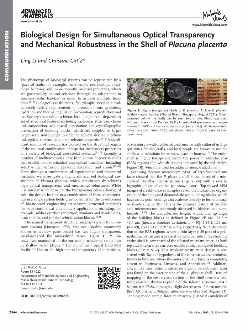
single-crystal calcite, respectively, which clearly indicates that the biogenic calcite is much more resistant to indentation pen-etration. Quantitative analysis using Oliver-Pharr (O-P) method gives (reduced modulus, hardness) pairs of (71.11 ± 3.25 GPa, 3.88 ± 0.17 GPa) and (70.09 ± 1.40 GPa, 2.51 ± 0.04 GPa) for P. placenta and single-crystal calcite, respectively (Figure 5 B). [ 38 ] While still maintaining the stiffness of calcite, P. placenta sig-nifi cantly enhances its resistance to plastic deformation as indi-cated by ∼ 55% increase in hardness relative to single-crystal calcite. When the maximum indentation load is increased to 8 mN with a sharp conospherical tip (nominal tip radius, ∼ 1 μ m; sem-angle, 30 ° ), the P. placenta shell and single-crystal calcite exhibit dramatically different fracture behaviors. In the latter, radial cracks and large fractured blocks can be clearly observed surrounding the indent crater (Figure 5 C). In con-trast, P. placenta shell exhibits a much more damage tolerant response (Figure 5 D), where the spatial extent of plastic defor-mation is greatly localized and isotropic; and fractured shell fragments in the deformation zone are nano-sized. Upon increasing the load to 30 N, the P. placenta shell is still able to maintain localized and isotropic deformation without any radial cracks, whereas large cracks along {104} planes readily form in single-crystal calcite samples (Figure 5 E and F). Such capability of deformation localization allows the shell to retain its integ-rity even if it is entirely penetrated, and multiple tests can be performed in a small region without breaking the shell (Figure 5 G and Inset). Similar tests on single-crystal calcite easily lead to fracture and shattering.
To the best of our knowledge, this work is the fi rst detailed study that explicitly examines the optical performance and mechanical properties of a natural mineralized transparent structural material system in correlation with its microstruc-tural and crystallographic features. The shell exhibits an intricate control of its structure at multiple length scales which allows it to simultaneously achieve high optical trans-parency and mechanical robustness. Macroscopically, the single foliated microstructure design leads to increased optical transparency relative to opaque mollusk shells which usually have multiple layers of different mineralized micro-structures in a single shell. Even an extra 20 μ m thick pris-matic layer in the PAS regions reduces the optical transmit-tance from ∼ 40% to 5%. Moreover, the absence of a usually-pigmented, exterior periostracum layer on P. placenta shells is also benefi cial to transparency, although it is a common shell component in other bivalves. [ 39 , 40 ] The shells are also thin and fl at, which enhances the transparency by reducing light scattering, absorption, and distortion. The nontrans-parent shells from a congeneric species, Placuna ephip-pium (Philipsson, 1788) are much thicker and highly curved (Figure S10). [ 17 ] It appears that the transparent P. placenta does not compromise its mechanical modulus and hardness to achieve the transparency as compared to the nontransparent P. ephippium at the length scale of the nanoindentation meas-urement (depth ∼ 150 nm, Figure S10). The geometric dis-advantages of the shell of P. placenta are likely compensated by its high stiffness in order to maintain its rigidity upon potential predatory attacks. [ 8 ] Microscopically, the variation of crystallographic orientations of the calcitic building blocks is responsible for the majority loss of the in-line transmission
© 2013 WILEY-VCH Verlag GAdv. Mater. 2013, 25, 2344–2350
due to the birefringence of calcite. This design, on the other hand, likely also contributes to the shell’s remarkable capabili-ties of crack localization, damage tolerance, and multi-attack resistance as compared to its main constituent, calcite, pos-sibly by disrupting dislocation motion and defl ecting micro-cracks. [ 41 ] The presence of the nanoscopic organic inclusions is believed to improve the shell’s fracture toughness and hard-ness relative to its pure mineral constituents possibly by pre-venting the dislocation of aligned slip planes, [ 42 , 43 ] while still maintaining low light scattering due to their small sizes.
Mechanical protection is usually considered the pri-mary task or function for mollusk shells, which are usually opaque. Although, at this stage, we cannot fully rule out the possibility that the observed transparency may only be a sec-ondary consequence of the special microstructure of the min-eralized shell in P. placenta , transparency as a camoufl age strategy for anti-predation has been found in several pelagic mollusk groups, including pterotracheid and carinariid het-eropods, pseudothecosomatous pteropods, and phylliroid nudibranchs, [ 44 ] some of which exhibit miniaturized trans-parent calcium carbonate based shells (e.g., Clio pyramidata and Limacina helicina , unpublished data). Optical transpar-ency has been shown to be a successful form of camoufl age to visual predation based on experimental and theoretical studies in terrestrial, freshwater, and marine systems. [ 44–46 ] As discussed above, the highly mineralized shell of P. placenta displays an intricate control of the material system at multiple length scales in order to achieve both optical transparency and mechanical robustness. Optical transparency induced camou-fl age might act as another driving force in the evolutionary development of the materials/microstructures of this mollusk species in order to maximize the organism’s survivability. The juvenile P. placenta shells are usually more transparent as compared to adult shells, and the transparency-induced cam-oufl age might be more effective as compared to mechanical protection from the small and thin shells at this stage. How-ever, we do not imply that being mechanically strong and opti-cally transparent are the only desired functions for mollusk shells. Other possible functions include mobility, [ 23 ] thermal protection, [ 8 ] and even other types of optical roles (e.g., bio-photonic coloration, [ 11 , 12 ] selective light diffusion, [ 13 ] and vision [ 14 ] ).
In conclusion, we have presented a detailed study of a highly mineralized mollusk shell that controls its microstructural/crystallographic features at multiple length scales in order to achieve high optical transparency as well as mechanical robust-ness. Whether or not this optical transparency is biologically utilized as camoufl age, this biological structural material system represents an excellent example of nature’s remarkable capability of engineering materials in order to achieve a desired set of diverse properties. In addition, the material design concepts reported here might lead to bio-inspired improve-ments in the design and application of engineering structural transparent materials.
Experimental Section Experimental details can be found in the supporting information.
2349wileyonlinelibrary.commbH & Co. KGaA, Weinheim
235
www.advmat.de
CO
MM
UN
ICATI
ON
Supporting InformationSupporting Information is available from the Wiley Online Library or from the author.
Acknowledgements We gratefully acknowledge support of the National Science Foundation MIT Center for Materials Science and Engineering (DMR-0819762), the US Army Research Offi ce through the MIT Institute for Soldier Nanotechnologies (Contract W911NF-07-D-0004), and the National Security Science and Engineering Faculty Fellowship Program (N00244-09-1-0064). The authors would like to thank Dr. Mathias Kolle for his assistance with microspectroscopy measurements and general discussion. We also thank Ria Tan for providing the photos of live animals. The authors also would like to thank Dr. Lin Han, Dr. Alan Schwartzman, Dr. Shiahn Chen, Dr. Yong Zhang, Dr. Lin Jia, and Matthew J. Connors for their technical assistance.
Received: November 6, 2012 Revised: February 1, 2013
Published online: March 1, 2013
[ 1 ] O. Shoval , H. S. Heftel , G. Shinar , Y. Hart , O. Ramote , A. Mayo , E. Dekel , K. Kavanagh , U. Alon , Science 2012 , 336 , 1157 .
[ 2 ] G. V. Lauder , S. M. Reilly , in Phylogenies and the Comparative Method in Animal Behavior , (Eds: E. P. Martins ), Oxford University Press , New York 1996 .
[ 3 ] B. O. Swanson , T. A. Blackledge , A. P. Summers , C. Y. Hayashi , Evo-lution 2006 , 60 , 2539 .
[ 4 ] J. Aizenberg , V. C. Sundar , A. D. Yablon , J. C. Weaver , G. Chen , Proc. Natl. Acad. Sci. USA 2004 , 101 , 3358 .
[ 5 ] J. W. C. Dunlop , P. Fratzl , Ann. Rev. Mater. Res. 2010 , 40 , 1 . [ 6 ] J. Song , S. Reichert , I. Kallai , D. Gazit , M. Wund , M. C. Boyce ,
C. Ortiz , J. Struct. Biol. 2010 , 171 , 318 . [ 7 ] B. J. F. Bruet , J. Song , M. C. Boyce , C. Ortiz , Nature Mater. 2008 , 7 ,
748 . [ 8 ] H. Yao , M. Dao , T. Imholt , J. Huang , K. Wheeler , A. Bonilla ,
S. Suresh , C. Ortiz , Proc. Natl. Acad. Sci. USA 2010 , 107 , 987 . [ 9 ] B. J. F. Bruet , H. J. Qi , M. C. Boyce , R. Panas , K. Tai , L. Frick ,
C. Ortiz , J. Mater. Res. 2005 , 20 , 2400 . [ 10 ] J. Aizenberg , J. C. Weaver , M. S. Thanawala , V. C. Sundar ,
D. E. Morse , P. Fratzl , Science 2005 , 309 , 275 . [ 11 ] D. J. Brink , N. G. van der Berg , A. J. Botha , Appl. Optics 2002 , 41 ,
717 . [ 12 ] D. J. Brink , N. G. van der Berg , J. Phys. D: Appl. Phys. 2005 , 38 ,
338 . [ 13 ] D. D. Deheyn , N. G. Wilson , Proc. R. Soc. B 2010 , 278 , 2112 . [ 14 ] D. I. Speiser , D. J. Eemisse , S. Johnsen , Curr. Biol. 2011 , 21 , 665 . [ 15 ] J. M. Sands , P. J. Patel , P. G. Dehmer , A. J. Hsieh , M. C. Boyce ,
Military Tech. 2008 , 12 , 82 .
0 wileyonlinelibrary.com © 2013 WILEY-VCH Verlag
www.MaterialsViews.com
[ 16 ] P. J. Patel , G. A. Gilde , P. G. Dehmer , J. W. McCauley , in Inorganic Optical Materials II , Vol. 4102 , (Eds: A. J. Marker III , E. G. Arthurs ), SPIE , 2002 , 1 .
[ 17 ] in The Living Marine Resources of the Western Central Pacifi c , Vol. 1 (Eds: K. E. Carpenter , V. H. Niem ), Food and Agriculture Organization of the United Nations , Rome , 1998 , 216 .
[ 18 ] A. G. Checa , F. J. Esteban-Delgado , A. B. Rodríguez-Navarro , J. Struct. Biol. 2007 , 157 , 393 .
[ 19 ] J. G. Carter , R. M. Hall , in Skeletal Biomineralization: Patterns, Proc-esses and Evolutionary Trends , Vol. 1 (Eds: J. G. Carter ) Van Nostrand Reinhold , New York 1990 .
[ 20 ] J. D. Taylor , Palaeontology 1973 , 16 , 519 . [ 21 ] H. D. Espinosa , A. L. Luster , F. J. Latourte , O. Y. Loh , D. Gregoire ,
P. D. Zavattieri , Nat. Commun. 2011 , 2 , 173 . [ 22 ] C. M. Zaremba , D. E. Morse , S. Mann , P. K. Hansma , G. D. Stucky ,
Chem. Mater. 1998 , 10 , 3813 . [ 23 ] M. J. Connors , H. Ehrlich , M. Hog , C. Godeffroy , S. Araya , I. Kallai ,
D. Gazit , M. Boyce , C. Ortiz , J. Struct. Biol. 2012 , 177 , 314 . [ 24 ] K. Gries , R. Kröger , C. Kübel , M. Fritz , A. Rosenauer , Acta Biomater.
2009 , 5 , 3038 . [ 25 ] J. S. Robach , S. R. Stock , A. Veis , J. Struct. Biol. 2005 , 151 , 18 . [ 26 ] X. Su , S. Kamat , A. H. Heuer , J. Mater. Sci. 2000 , 35 , 5545 . [ 27 ] F. Heinemann , M. Launspach , K. Gries , M. Fritz , Biophys. Chem.
2011 , 153 , 126 . [ 28 ] R. T. Dehoff , F. N. Rhines , in Quantitative Microscopy . McGraw-Hill ,
New York 1968 . [ 29 ] D. G. Jensen , J. Phys. D: Appl. Phys. 1995 , 28 , 549 . [ 30 ] M. Wakaki , K. Kudo , T. Shibuya , in Physical Properties and Data of
Optical Materials , CRC Press , 2007 , 89 . [ 31 ] J. Zhao , B. Zhou , B. Liu , W. Guo , J. Comput. Theor. Nanosci. 2009 , 6 ,
1181 . [ 32 ] R. Apetz , M. P. B. van Bruggen , J. Am. Ceram. Soc. 2003 , 86 ,
480 . [ 33 ] I. Yamashita , H. Nagayama , K. Tsukuma , J. Am. Ceram. Soc. 2008 ,
91 , 2611 . [ 34 ] C. Matzler , MATLAB functions for Mie Scattering and Absorption
(Version 2) , University of Bern , 2002 . [ 35 ] A. M. Sweeney , D. L. Des Marais , Y. E. A. Ban , S. Johnsen , J. R. Soc.
Interface 2007 , 4 , 685 . [ 36 ] J. Voros , Biophys. J. 2004 , 87 , 553 . [ 37 ] J. G. J. Peelen , R. Metselaar , J. Appl. Phys. 1974 , 45 , 216 . [ 38 ] W. C. Oliver , G. M. Pharr , J. Mater. Res. 1992 , 7 , 1564 . [ 39 ] A. Checa , Tissue & Cell 2000 , 32 , 405 . [ 40 ] R. E. Hillman , Science 1961 , 134 , 1754 . [ 41 ] J. R. Greer , J. T. M. De Hosson , Prog. Mater. Sci. 2011 , 56 , 654 . [ 42 ] Y. Y. Kim , K. Ganesan , P. Yang , A. N. Kulak , S. Borukhin , S. Pechook ,
L. Ribeiro , R. Kroger , S. J. Eichhorn , S. P. Armes , B. Pokroy , F. C. Meldrum , Nat. Mater. 2011 , 10 , 890 .
[ 43 ] Y. Ma , S. R. Cohen , L. Addadi , S. Weiner , Adv. Mater. 2008 , 20 , 1555 .
[ 44 ] S. Johnsen , Biol. Bull. 2001 , 201 , 301 . [ 45 ] S. Johnsen , E. A. Widder , Biol. Bull. 1998 , 195 , 337 . [ 46 ] S. Johnsen , E. A. Widder , Mar. Biol. 2001 , 138 , 717 .
GmbH & Co. KGaA, Weinheim Adv. Mater. 2013, 25, 2344–2350

Copyright WILEY-VCH Verlag GmbH & Co. KGaA, 69469 Weinheim, Germany, 2013.
Supporting Information for Adv. Mater., DOI: 10.1002/adma.201204589 Biological Design for Simultaneous Optical Transparency and Mechanical Robustness in the Shell of Placuna placenta Ling Li and Christine Ortiz*

1
Supporting information
for
Biological Design for Simultaneous Optical Transparency and Mechanical Robustness in the Shell of Placuna placenta
Ling Li and Christine Ortiz* ([email protected])
1. Experimental
Samples: Pre-trimmed P. placenta shell specimens (diameter: ~50 mm) were purchased from Seashell World (FL, United States). Intact P. placenta shells were purchased from Conchology, Inc (Philippines).
Microscopy (optical microscopy, scanning electron microscopy, transmission electron microscopy and atomic force microscopy): Optical images were taken with a Nikon ECLIPSE LV100 microscope (Tokyo, Japan). Samples were imaged using Helios Nanolab 600 Dual Beam (FEI, OR) at the acceleration voltage of 5 keV and working distance of 4 mm. TEM observations were obtained using a JEOL 2011 operated at 80 and 120 keV, and a JEOL 2010F operated at 200 keV. The image magnification and camera constants were calibrated using a standard sample (MAG*I*CAL, Electron Microscopy Sciences, PA, USA). A Digital Instruments Multimode SPM IIIA (Veeco, Santa Barbara, CA) was used with AS-130 “JV” scanners. Tapping mode AFM (TMAFM) imaging was conducted with NANOSENSORS Si TMAFM cantilevers (PPP-NCHR-10). Structural analysis: Powder X-ray diffraction spectrums were obtained using Rigaku powder diffractometers with a rotating anode generator and 180 mm Bragg-Brentano diffractormeter, operating at 250 kV and 50 mA between 20 and 90º (2θ). Electron backscattered diffraction analysis was carried out using a FEI Helios FIB/SEM system equipped with the HKL Technology “Channel 5” EBSD system (Schmidt and Olesen 1989; Randle and Engler 2000). Thermogravimetric analysis: The shells were first ground with a pestle and mortar. Samples were then vacuum dried at 110°C overnight to remove residual water. TGA was carried out from 100 to 500°C at 2.5°C/min on a TA Instruments TGA Q50 (New Castle, DE). Nano- and Macro-indentation: Nanoindentation experiments were conducted in ambient conditions using a Hysitron, Inc. (Minneapolis, MN) Triboindenter. The standard Oliver-Pharr (O-P) methodology was used to quantify the indentation modulus and hardness.[1] Macroindenation experiments were conducted in ambient conditions using a Zwick mechanical testing instrumentr (Zwick Z010, Zwick Roell, Germany). The load was measured with a 10 kN load cell. The surface roughness from the nanoasperities on the

2
freshly-cleaved shell samples is on the order of 4 nm, as compared to ~150 nm, the minimum depth applied in the indentation tests. Total and in-line transmission and Microspectroscopy: Macroscopic optical in-line transmittance of samples with different thickness was measured using a Cary 5E UV-Vis-NIR Dual-Beam spectrophotometer in the wavelength range of 200-800 nm. The total forward transmission was measured using the spectrophotometer equipped with an integrating sphere. A modified Leica DMRX microscope was used to carry out parallel optical imaging and spectroscopic spatial optical mapping (reflection and transmission) at microscopic level. 2. Supporting figures
Figure S1. SEM micrographs of A) outer, B) inner surface of the foliated microstructure, and C) PAS area.
Figure S2. A-B) SEM and C) AFM images of interface between PAS and foliated structure.
3
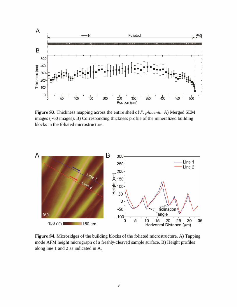
Figure S3. Thickness mapping across the entire shell of P. placenta. A) Merged SEM images (~60 images). B) Corresponding thickness profile of the mineralized building blocks in the foliated microstructure.
Figure S4. Microridges of the building blocks of the foliated microstructure. A) Tapping mode AFM height micrograph of a freshly-cleaved sample surface. B) Height profiles along line 1 and 2 as indicated in A.
4
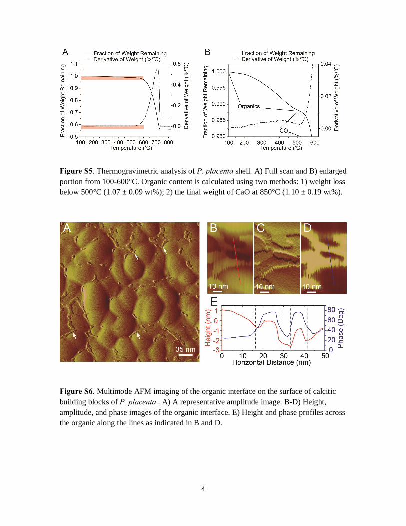
Figure S5. Thermogravimetric analysis of P. placenta shell. A) Full scan and B) enlarged portion from 100-600°C. Organic content is calculated using two methods: 1) weight loss below 500°C (1.07 ± 0.09 wt%); 2) the final weight of CaO at 850°C (1.10 ± 0.19 wt%).
Figure S6. Multimode AFM imaging of the organic interface on the surface of calcitic building blocks of P. placenta . A) A representative amplitude image. B-D) Height, amplitude, and phase images of the organic interface. E) Height and phase profiles across the organic along the lines as indicated in B and D.

5
Figure S7. Quantitative analysis of the intracrystalline inclusion size through stereological correction.[2] fA: the relative frequency of inclusions of a certain size group counted in a unit area based on TEM images; fV: the calculated frequency of particles of a certain size groups counted in a unit volume from stereological correction, which is further fitted with the following log-normal distribution [3]:
2
2
2
(ln ln )2
12
1( )2
mr r
m
f r er e
σ
σπσ
−−
=
Figure S8. Powder X-ray diffraction spectrum of P. placenta with standard calcite peaks (PDF #01-075-6049).

6
Figure S9. Averaged transmission and reflection spectrums of P. placenta shell based on the microspectroscopy measurements.
Figure S10. A) Picture of transparent P. placenta (edge trimmed) and its cogeneric species, non-transparent P. ephippium. B) Averaged load-depth curves for P. placenta and P. ephippium. C) Distribution of reduced modulus and hardness.
Reference:
[1] W. C. Oliver, G. M. Pharr, J. Mater. Res. 1992, 7, 1564.
[2] D. G. Jensen, J. Phys. D: Appl. Phys. 1995, 28, 549.
[3] J. G. J. Peelen, R. Metselaar, J. Appl. Phys. 1974, 45, 216.
Related Documents