Bioactive glass coatings by suspension plasma spraying from glycolether- based solvent feedstock E. Cañas * , M. Vicent, M.J. Orts, E. Sánchez Instituto de Tecnología Cerámica (ITC), Asociación de Investigación de las Industrias Cerámicas (AICE), Universitat Jaume I, 12006, Castellón, Spain Eugeni Cañas Recacha Telephone number: (+34) 964342424 Email: [email protected] Fax number: (+34) 964342425 Mónica Vicent Cabedo Email: [email protected] María José Orts Tarí Email: [email protected] Enrique Sánchez Vilches Email: [email protected]

Welcome message from author
This document is posted to help you gain knowledge. Please leave a comment to let me know what you think about it! Share it to your friends and learn new things together.
Transcript

Bioactive glass coatings by suspension plasma spraying from glycolether-
based solvent feedstock
E. Cañas*, M. Vicent, M.J. Orts, E. Sánchez
Instituto de Tecnología Cerámica (ITC), Asociación de Investigación de las Industrias
Cerámicas (AICE), Universitat Jaume I, 12006, Castellón, Spain
Eugeni Cañas Recacha Telephone number: (+34) 964342424
Email: [email protected] Fax number: (+34) 964342425
Mónica Vicent Cabedo
Email: [email protected]
María José Orts Tarí
Email: [email protected]
Enrique Sánchez Vilches
Email: [email protected]
2
Abstract
Bioactive glasses are emerging as a substitute of hydroxyapatite in the development of
bioactive coatings for biomedical applications. The deposition of these coatings is carried out
by a wide range of methods, being atmospheric plasma spraying the most employed
technique. However, the research on the deposition of these coatings from suspension
feedstocks by thermal spraying is still incipient, therefore more research about this topic is
needed.
Thus, a bioactive glass suspension, composed of fine glass particles, was prepared and
stabilised through rheological and sedimentation tests to be used as a feedstock in plasma
spraying. The solvent used in the suspension preparation was dipropylene glycol methyl ether
in order to develop a new type of bioactive suspension. Consequently, as a new type of
solvent was used, its effect on the plasma torch properties was determined. On other hand, the
rheological behaviour of the suspension feedstock was assessed by means of a simple
viscosity model.
This suspension was deposited onto metallic substrates by plasma spraying, employing
several spraying distances. All coatings displayed a suitable adherence and similar thickness.
However, the microstructure of the obtained coatings is highly affected by the spraying
distance as it can be seen in coatings surface and cross-section field emission gun
environmental scanning electron microscopy examination. Thus, a relation between the
spraying distance and coatings microstructure was found. On the other hand, X-ray diffraction
confirmed the amorphous nature of the obtained coatings.
Keywords: Bioactive glass suspensions characterisation; Ability of heating factor; Suspension
plasma spraying; Bioactive glass coatings

3
1. Introduction
Hydroxyapatite has been long used as bioactive coating for medical applications owing to the
similarity of its composition with that of the bone tissue of the human body. However, a new
bioceramic which displays the same bioactivity than hydroxyapatite but whose synthesis
process is simpler has recently emerged. This is bioactive glass (BG), an amorphous material
exhibiting a high index of bioactivity [1,2]. Numerous techniques such as electrophoretic
deposition, sol-gel, enamelling, laser deposition or thermal spray techniques have been
employed to obtain such coatings. However, thermal spray techniques and more specifically
Atmospheric Plasma Spraying (APS) is the most used method due to the high temperatures
reached in the plasma torch and the subsequent fast cooling of the deposited material so that
the devitrification of the as-coated glass is inhibited [3,4].
In recent years, within the group of thermal spray techniques Suspension Plasma Spraying
(commonly known as SPS) has developed as a new method of coating deposition. SPS
method is similar to APS with the difference that the material injected into the plasma torch is
a suspension rather than a powdery material. One of the main advantages of SPS against APS
process deals with the possibility of incorporating small particles (submicron- or even nano-
sized) through the liquid [5]. Although there are numerous research groups depositing
coatings from suspensions of different types of ceramic materials, mainly oxides, only few
groups have started to work with bioactive glass particles, so that this research line is still
incipient [6,7].
On other hand, BG suspensions cannot be prepared in water due to its tendency to leach into
this medium, resulting in gelation phenomena. For that reason, one of the challenges of the
SPS feedstock preparation is to stabilise the glass particles together with the necessary
additives (dispersant, thickener, suspending, etc.) in an organic solvent that is manageable and
safe during thermal spraying. Although ethanol has been mostly used in BG suspensions
preparation, our research group has very recently reported the use of an alternative solvent

4
(dipropylene glycol methyl ether, hereafter DGME) which also accomplishes with technical
and safety requirements of the process [8]. Thus, whereas the physical properties of both
solvents (viscosity and surface tension) are quite similar, DGME displays higher flash point
than ethanol making handle, storage and transport of suspensions containing this solvent safer
and easier.
The literature reports many papers about optimisation of plasma spray conditions to obtain
BG coatings by APS. Most of these papers also include the characterisation of the resulting
coatings [9–14]. However, very limited numbers of papers have dealt with obtaining BG
coatings by SPS technique. This research has shown that the microstructure of SPS-BG
coatings is characterised by a two-zone feature: one zone associated with well-molten
particles which result in dense and flat areas and another agglomerated zone made up of fine
and partially sintered grains [15]. Bolelli et al have also confirmed these microstructure
features of SPS-BG coatings whereas at the same time these authors highlight the significant
differences of SPS and APS coating microstructures [16]. Not least, these authors also point
out that the SPS microstructure is very sensitive to the properties of the suspension feedstock
(glass particle size, solids content, dispersion state…). As a result, the research on the
suspension feedstock requirements to establish a suitable SPS process represents a matter of
paramount importance.
In a recent paper with APS-BG coatings, the authors have shown that the abundance of round
pores in the microstructure of these coatings is consequence of a liquid phase sintering
mechanism operating during the thermal treatment of glassy particles [17]. For this reason,
the SPS feedstock characteristics are expected to strongly affect the liquid phase sintering of
the as-sprayed glass particles as well as on the evolving of gas bubbles occurring during the
rapid sintering of melted glass particles. Nevertheless, the research on microstructure
development in SPS-BG coatings as well as the relationships between suspension feedstock
characteristics and coating microstructure and properties are still in a preliminary stage.

5
Otherwise, unlike conventional thermal spraying with dry feedstocks, in SPS the evaporation
of the solvent tends to change the chemical composition of the plasma working gases giving
rise to a modification of the transport properties of the plasma torch, which determine particle
velocity and temperature. Hence, it is indispensable to address the effect caused in the plasma
torch by the injected solvent in order to optimise the spraying parameters and achieve an
energetic torch where the flying particles or agglomerates can properly melt.
Consequently, the aim of the present work is to contribute to better understanding of the
development of the microstructure of SPS-BG coatings. In this research, a SPS feedstock of a
given BG powder containing DGME as solvent will be used. This feedstock was prepared and
stabilised in a previous research [8]. A viscosity model was also tested to accomplish with
flow requirements of the feedstock suspension during the SPS operation. In addition, the
effect of this solvent on the plasma torch was studied by calculating the ability of heating
factor (AHF) and the degree of melting factor (DMF). Finally, during coatings deposition,
spray distance was varied with the aim of developing different coating microstructures.
Surface and cross-section microstructures of the obtained coatings were examined by field
emission gun environmental scanning electron microscope (FEG-ESEM), and phase coating
distribution was determined by X-ray diffraction (XRD).

6
2. Experimental
2.1. Synthesis and characterisation of the bioactive glass suspension
Home-made bioactive glass powders were used to prepare the desired feedstock suspension.
These powders showed the following characteristics: amorphous character, particle size lower
than 63 µm and an oxide composition (in wt%) of 47.6 SiO2 – 5.3 P2O5 – 23.1 CaO – 24.0
Na2O. This glass powder was obtained by the melting and quenching method [17]. To prepare
the suspension, the glass powders were mixed with DGME solvent (Dowanol DPM, Dow
Chemical, USA) with a proportion of 10 vol.% of solids and 90 vol.% of solvent, employing
0.5 wt% (relative to solids content) of D190 (Disperbyk–190, Byk, Germany) as a dispersant
agent to stabilise the suspension. The reasons for the choice of DGME as feedstock solvent as
well as the comparison between this solvent and ethanol (the solvent commonly used in SPS)
in terms of physical properties and handling and safety requirements are detailed in a previous
work [8]. The mixture was wet-milled several times in order to reach finer particle sizes,
following the procedure described in the above paper [8] and obtaining a bioactive glass
suspension (referred to as BGS) which was used as feedstock in the SPS process.
From the obtained suspension (BGS), viscosity and thixotropy were determined through a
rheological characterisation. For that purpose, a rheometer (Haake RS50, Thermo Scientific,
Germany) which controls the rate (CR) was used operating at 298 K and using a double-cone
and plate system. The assay carried out to determine both viscosity and thixotropy, consists in
loading the shear rate from 0 to 1000 s-1
in 5 minutes, maintaining the shear rate at 1000 s-1
during 1 minute and downloading it from 1000 to 0 s-1
in 5 minutes. Moreover, the stability
with time of the obtained suspension was assessed by sedimentation test [18]. This test was
carried out in a multiple light scattering equipment (TurbiScan Classic MA2000,
Formulaction, France) which is able to measure the amount of light backscattered or
transmitted by the suspension in function of time. For that aim, one test was performed for 1
hour, a second test for 15 hours and another test for 24 hours.

7
On the other hand, density of the BGS was determined using a pycnometer, particle size
distribution was measured by laser diffraction (Mastersizer 2000, Malvern Instruments, Great
Britain) and morphology of the suspension solid material was assessed by FEG-ESEM
(QUANTA 200FEG, FEI Company, USA) after drying in an oven (383 K) a sample of the
BGS.
2.2. Plasma torch transport properties
In a system consisting of a particle inside a plasma (assuming unique temperature for either
the solid or the plasma) the heat transferred from the plasma to the particle could be described
by the following expression (equation 1) [19–21].
𝜋𝑑𝑝2ℎ(𝑇𝑔 − 𝑇𝑝) + ℎ𝑟(𝑇𝑔) =
1
6𝜋𝜌𝑝𝑐𝑝𝑑𝑝
3 𝑑𝑇𝑝
𝑑𝑡+ 𝜋𝑑𝑝
2𝜀𝑝𝜎𝑇𝑝4
(1)
Where dp is the particle diameter (m), h is the conduction heat transfer coefficient (W m-2
K-
1), Tg is the plasma temperature (K), Tp is the particle temperature (K), hr is the radiative heat
transfer coefficient (W m-2
K-1
), ρp is the particle density (kg m-3
), cp is the particle specific
heat (J K-1
kg-1
), εp is the particle radiative emission coefficient and σ is the Stefan-Bolzmann
constant.
Considering the assumptions made by Pawlowski [19], equation 1 can be written as follows:
𝐴𝐻𝐹 =𝐿(𝑇𝑔−𝑇𝑝)
2(⟨𝜆𝑔⟩)
2
⟨𝜂𝑔⟩𝑣𝑔=
𝐻𝑚2 𝑑𝑝
2⟨𝜌𝑝⟩
16= 𝐷𝑀𝐹 (2)
Where L is the length of the high temperature zone of the plasma (m), <λg> is the plasma
average thermal conductivity (W m-1
K-1
), <ηg> is the plasma average dynamic viscosity (kg
m-1
s-1
), vg is the plasma velocity of the high temperature zone (m s-1
) and Hm is the particle
fusion enthalpy (J kg-1
).
In equation 2, the left-hand side contains all variables related to the plasma torch and its
transport properties being this side known as the ability of heating factor (AHF), whereas the

8
right-hand side contains all variables related to the particle and is known as the difficulty of
melting factor (DMF). Therefore, a particle with a diameter dp will be melted if AHF > DMF.
In the present work, since a new solvent different from the commonly used (ethanol) was
employed to develop the suspensions, the effect of that solvent on the torch properties has
been determined. For that purpose, a modified ability of heating factor (AHFm) was calculated
[20,21], which only depends of the transport properties, i.e. average thermal conductivity
(<λg>) which affects the heat and momentum transfer (particles temperature and velocity) and
dynamic viscosity (<ηg>) which only affects the momentum transfer (particles velocity).
Thus, the left-hand side of equation 2 can be written as follows:
1
(𝑇𝑔−𝑇𝑝)√𝐴𝐻𝐹𝑣𝑔
𝐿=
⟨𝜆𝑔⟩
√⟨𝜂𝑔⟩= 𝐴𝐻𝐹𝑚 (3)
Moreover, the AHF and DMF were also calculated from equation 2.
2.3. Suspension deposition and coatings characterisation
The development of the bioactive coatings was done employing a thermal spraying facility,
comprised by a plasma torch (F4-MB, Oerlikon Metco, Switzerland) coupled to a six axes
robot (IRB 1400, ABB, Switzerland). The feeding system was adapted to spray suspensions by
mechanical injection assisted by air pressure with a maximum pressure of 6 bar. More details
about the SPS equipment have been reported in previous works [22,23].
The substrates employed to obtain the bioactive coatings were discs with a diameter of 25 mm
made of AISI type 304 stainless steel, which were grit-blasted using black corundum with a
pressure of 4.2 Pa and were cleaned with ethanol prior to the deposition of the bioceramic
layer. Thus, substrates with a roughness value (Ra) of 2.2 ± 0.1 µm were obtained, being this
value measured in a roughness tester (HOMMELWERKE T8000, Hommelwerke GmbH,
Germany). In addition, before coatings deposition, all substrates were coated with a bond coat
to enhance the adherence of the final coating. This layer was deposited from anatase

9
feedstocks (Metco 102, Oerlikon Metco, Switzerland) with a particle size distribution between
10 and 55 µm by atmospheric plasma spraying (APS) and using the spraying parameters given
by the supplier (Table 1).
Finally, bioactive coatings were deposited with the facility described above, preheating the
substrates coated with the bond coat between 300 °C and 350 °C (to further increase of the
adherence of the glass coating). The plasma working gases used were a mixture of argon as
primary gas and hydrogen as secondary gas. The spraying conditions utilised in this work are
detailed in table 1, and as it can be observed, several (5) spraying distances were tested in
order to develop coatings with different microstructure.
Regarding the characterisation, all coatings were XRD analysed using a diffractometer
(Advance diffractometer, Bruker Theta-theta, Germany) to determine their nature (amorphous
or crystalline), and were observed in both surface and section by FEG-ESEM to examine the
microstructure obtained for each coating in function of the spraying distance.

10
3. Results and discussion
3.1. Bioactive glass suspension
The BGS, with a density of 1077 kg m-3
, presents a narrow monomodal particle size
distribution, with a D50 of 2.3 ± 0.2 µm. In addition, all glass particles display quite similar
angular-shape (Figure 1) which corresponds to the typical morphology of milled frit particles.
Thixotropy and viscosity of the BGS were estimated from the flow curve (Figure 2) obtained
from the rheological test. In the range of shear rates tested (from 1 to 1000 s-1
) the suspension
shows a pseudoplastic behaviour, with a low thixotropic cycle of 258 Pa s-1
and a low average
viscosity value of 5.6·10-3
Pa s (measured at 500 s-1
in uploading step), being a priori suitable
for the injection into the plasma torch (low viscosity requirement as well as little variation
with time).
To determine the real viscosity of the BGS at different points of the plasma spraying facility
(stored at hopper, pumped within the pipes and injected to the torch through the injector), the
experimental data from the obtained viscosity curve were adjusted to the Cross model. Unlike
other models, this model allows to predict viscosity values for both low and high shear rates
[24]. The model equation reads as follows:
𝜂𝑜−𝜂
𝜂−𝜂∞= (𝐾 · ��)𝑚 (4)
Where η is the suspension viscosity (Pa s) at a given shear rate γ (s-1
), ηo (Pa s) and η∞ (Pa s)
are the viscosity limit values extrapolated to cero and infinite velocity respectively, and K (s)
and m (dimensionless) are fit constants. The parameters used for the adjustment are displayed
in table 2, and figure 3 exposes the adjustment of the experimental values with the Cross
model. As it can be observed these values fit well to the theoretical model. Only a little
deviation from the model occurs at high shear rates in the downloading step due to the
thixotropy, which causes a reduction in viscosity when the shear rate decreases.
Then, the rheological behaviour of the BGS was assessed at different points of the plasma
equipment from the model for the shear rate of each point. The results are showed in table 3

11
and the viscosity of each point is highlighted in figure 3 with a triangle dot. As expected the
suspension exhibits high viscosity during its storage since no shear is acting; nevertheless,
during transport and injection, a dramatic decrease of the suspension viscosity occurs due to
the increment of the shear rate, which is consequence of the little diameter of the pipe and the
injector. In addition, the viscosity in the injector is even slightly lower than the average
viscosity obtained from the rheological test. This low viscosity as well as a little variation of
viscosity with time (low thixotropy) are key requirements for the suspension feedstock in a
SPS process as reported elsewhere [25].
Otherwise, figure 4 sets out the results of the sedimentation tests. As previously reported,
sedimentation tests in a multiple light scattering equipment allow to determine the stability of
the suspensions [18]. As a result of the test, a few curves are obtained, which represents the
percentage of light backscattered or transmitted as a function of glass cell height. Thus, for
one hour the suspension is quite stable, since no sedimentation occurs as figure 4a shows.
However, for 15 and 24 hours, the sedimentation of coarse particles takes place as it can be
seen in figures 4b and 4c. However, as the suspension is easily redispersable, it would be
enough to agitate this sediment to obtain again a stable suspension for one more hour. This
time of stability can be considered sufficient for the SPS process. In fact, the estimated time
that the suspension stays in the SPS container and circuit for a real sample could be lower
than 1 hour, in function of type and dimensions of the sample (screw of a dental implant, hip
prosthesis, etc). In these cases, the redispersion of the suspension by simple agitation would
be the procedure to be followed.
3.2. Effect of solvent injection in the plasma torch properties
From the spraying parameters used (Table 1) the average dynamic viscosity and thermal
conductivity were calculated from 300 K until the plasma high temperature Tg = 10063 K, by
means of the free software Jet&Poudres [26]. The calculations were done, employing the free

12
software T&TWinner [27,28] for the plasma gases as well as for the mixture of plasma gases
and the evaporated solvent of the suspension (DGME). Furthermore and for comparison
purpose, these calculations were also done for the mixture of plasma gases and ethanol at the
same spraying conditions. Then, from the average dynamic viscosity and thermal
conductivity, the modified ability of heating factor was calculated by equation 3 and the
results are showed in table 4.
From the results, it can be stablished that the injection of a solvent (indistinctly the type of
solvent) into the plasma torch, reduces the torch viscosity and increases its thermal
conductivity, resulting in an increment of the ability of heating factor. However, there are
differences between the solvents (minimal differences), since high thermal conductivity and
therefore high modified ability of heating factor were obtained for ethanol due to its lower
molecular weight and its high ability to evaporate easily. Even so, it is evident the positive
effect of the DGME into the transport properties, since the AHFm is increased almost twice
with regard the AHFm of the torch.
Moreover, the AHF and the DMF factors were calculated by equation 2 for the mixture of
plasma gases with the injection of the BGS, where the length and velocity of the high
temperature zone of plasma were also obtained from the free software Jet&Poudres. The
results are showed in table 5, where it can be seen the effect observed above, since the
injection of the BGS into the plasma torch increases the ability of the working gases to melt
solid particles. Otherwise, the AHF of these gases, with and without DGME, is higher than
the DMF ensuring the complete melting of the particles.
3.3. Bioactive glass coatings
Once a stable feedstock suspension was obtained, it was deposited by SPS under the spraying
conditions displayed in table 1. Figure 5 shows the micrographs (both surface and cross-
section pictures) of the obtained coatings at the five spraying distances tested.
13
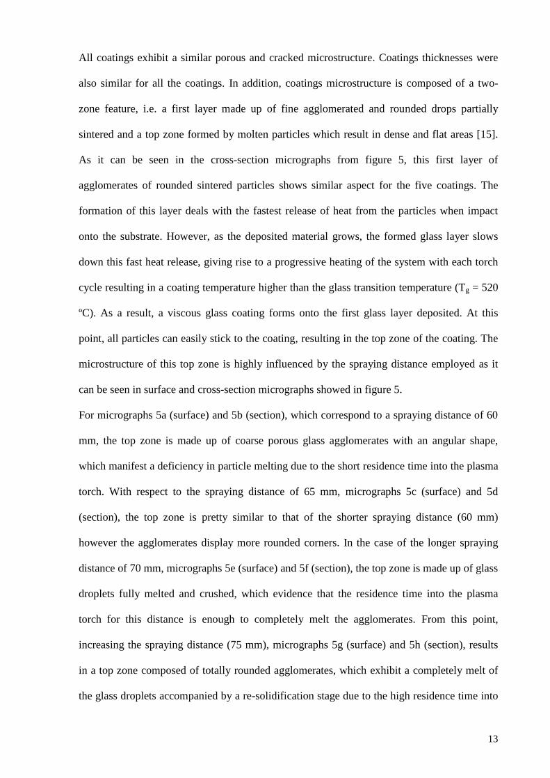
All coatings exhibit a similar porous and cracked microstructure. Coatings thicknesses were
also similar for all the coatings. In addition, coatings microstructure is composed of a two-
zone feature, i.e. a first layer made up of fine agglomerated and rounded drops partially
sintered and a top zone formed by molten particles which result in dense and flat areas [15].
As it can be seen in the cross-section micrographs from figure 5, this first layer of
agglomerates of rounded sintered particles shows similar aspect for the five coatings. The
formation of this layer deals with the fastest release of heat from the particles when impact
onto the substrate. However, as the deposited material grows, the formed glass layer slows
down this fast heat release, giving rise to a progressive heating of the system with each torch
cycle resulting in a coating temperature higher than the glass transition temperature (Tg = 520
ºC). As a result, a viscous glass coating forms onto the first glass layer deposited. At this
point, all particles can easily stick to the coating, resulting in the top zone of the coating. The
microstructure of this top zone is highly influenced by the spraying distance employed as it
can be seen in surface and cross-section micrographs showed in figure 5.
For micrographs 5a (surface) and 5b (section), which correspond to a spraying distance of 60
mm, the top zone is made up of coarse porous glass agglomerates with an angular shape,
which manifest a deficiency in particle melting due to the short residence time into the plasma
torch. With respect to the spraying distance of 65 mm, micrographs 5c (surface) and 5d
(section), the top zone is pretty similar to that of the shorter spraying distance (60 mm)
however the agglomerates display more rounded corners. In the case of the longer spraying
distance of 70 mm, micrographs 5e (surface) and 5f (section), the top zone is made up of glass
droplets fully melted and crushed, which evidence that the residence time into the plasma
torch for this distance is enough to completely melt the agglomerates. From this point,
increasing the spraying distance (75 mm), micrographs 5g (surface) and 5h (section), results
in a top zone composed of totally rounded agglomerates, which exhibit a completely melt of
the glass droplets accompanied by a re-solidification stage due to the high residence time into

14
the cold zones of the plasma torch. Consequently, the re-solidified agglomerates can be
attached to the viscous glass layer, but cannot coalesce between them. The same occurs for a
longer distance (80 mm) as it can be seen in micrographs 5i (surface) and 5j (section).
However, the rounded agglomerates of this coating are smaller than those of the shorter
distance (75 mm) because they are not so crushed, since the longer distance gives rise to a
higher degree of solidification, and therefore lower ability to deform when agglomerates
impact on the substrate.
To sum up, all coatings display a microstructure with the same first layer, but a different top
zone in function of the spraying distance show up whereas all of these top zones show the
“cone shaped” structure [8]. Nevertheless, it is clear that the optimum spraying distance for
the spraying conditions employed in this research corresponds to 70 mm. Furthermore, a
relation between coatings microstructure and the spraying distance was found, since there is
an optimum spraying distance. Hence below this distance, particles do not sufficiently melt
but above it particles melt and partially re-solidify.
Finally, all coatings were analysed by XRD. As it can be seen in figure 6, the coating
preserves the amorphous nature of the starting feedstock, allowing them to develop its
bioactivity. The diffractogram showed in figure 6 corresponds to the coating deposited for a
distance of 80 mm, but the other coatings show similar patterns.

15
4. Conclusions
A bioactive glass suspension was obtained for its use as a feedstock in a SPS process. The
suspension average viscosity was very low, allowing suspension injection into the plasma
torch without any difficulty. In addition, the obtained suspension is quite stable, since for one
hour no sedimentation occurs, however, for longer periods of time, a little amount of settled
solid was formed, which could be suspended again by a simple agitation. Moreover, the
viscosity of the feedstock suspension was fitted to the Cross model, obtaining a reasonably
good adjustment. Through this model, it can be seen that the real viscosity of the suspension
when is injected through the injector nozzle is lower than the average suspension viscosity,
therefore the requirement of low viscosity imposed to suspension feedstock employed in SPS
is met.
The effect of the new suspension solvent (DGME) onto the plasma torch properties was
analysed. The positive effect for the plasma spraying process when this solvent is used has
been proved, since the thermal conductivity and therefore the AHF parameter were increased
almost twice.
Finally, bioactive coatings were obtained through the deposition of the feedstock suspension
by SPS, employing different spraying distances. All coatings showed similar porous and
cracked microstructure, made up of two different zones, as reported in the literature for the
SPS process. However, a clear relation between the spraying distance and the microstructure
of the obtained coating can be appreciated since for the shorter spraying distances (60 and 65
mm) the agglomerates formed in the top layer partially melt showing an angular shape, due to
the shorter residence time into the plasma torch. On the contrary, for the rest of the spraying
distances (70, 75 and 80 mm), the residence time was enough to completely melt the particles.
Furthermore, for the distances of 75 and 80 mm, the residence time is so high that the
particles melt and partially solidify before the impact on the substrate. Thus, the optimal

16
spraying distance for the conditions used in this research is 70 mm. On other hand, all
coatings showed amorphous nature, allowing them to develop their bioactivity.
Acknowledgements
The authors of the present work thank Universitat Jaume I of Castellón the support provided
in funding RECUBIO project (P1–1B2013–69) and action 3.1. of the Research Promotion
Plan (PREDOC/2015/50), and Prof. Rodrigo Moreno (ICV-CSIC, Madrid, Spain) for his
kindly contribution in the rheological characterisation.

17
References
[1] L. Lefebvre, L. Gremillard, J. Chevalier, R. Zenati, D. Bernache-Assolant, Sintering
behaviour of 45S5 bioactive glass, Acta Biomater. 4 (2008) 1894–1903.
[2] G. Goller, H. Demirkiran, F.N. Oktar, E. Demirkessen, Processing and characterization
of bioglass reinforced hydroxyapatite composites, Ceram. Inter. 29 (2003) 721–724.
[3] A. Sola, D. Bellucci, V. Canillo, A. Cattini, Bioactive glass coatings: a review, Surf.
Eng. 27 (2011) 560–573.
[4] G. Bolelli, V. Canillo, L. Lusvarghi, T. Manfredini, C. Siligardi, C. Bartuli, A. Loreto,
T. Valente, Plasma-sprayed glass-ceramic coatings on ceramic tiles: microstructure, chemical
resistance and mechanical properties, J. Eur. Ceram. Soc. 25 (2005) 1835–1853.
[5] P. Fauchais, M. Vardelle, A. Vardelle, S. Goutier, What do we know, what are the
current limitations of suspension plasma spraying?, J. Therm. Spray Technol. 24 (2015)
1120–1129.
[6] G. Bolelli, D. Bellucci, V. Cannillo, R. Gadow, A. Killinger, L. Lusvarghi, P. Müller,
A. Sola, Comparison between suspension plasma sprayed and high velocity suspension flame
sprayed bioactive coatings, Surf. Coat. Technol. 280 (2015) 232–249.
[7] D. Bellucci, G. Bolelli, V. Cannillo, R. Gadow, A. Killinger, L. Lusvarghi, A. Sola, N.
Stiegler, High velocity suspension flame sprayed (HVSFS) potassium-based bioactive glass
coatings with and without TiO2 bond coat, Surf. Coat. Technol. 206 (2012) 3857–3868.
[8] E. Cañas, M. Vicent, M.J. Orts, R. Moreno, E. Sánchez, Bioactive glass suspensions
preparation for suspension plasma spraying, J. Eur. Ceram. Soc. (2016) DOI:
http://dx.doi.org/10.1016/j.jeurceramsoc.2016.06.011.
[9] M. Monsalve, H. Ageorges, E. Lopez, F. Vargas, F. Bolivar, Bioactivity and mechanical
properties of plasma-sprayed coatings of bioglass powders, Surf. Coat. Technol. 220 (2013)
60–66.
[10] X. Chen, M. Zang, X. Pu, G. Yin, X. Liao, Z. Huang, Y. Yao, Characteristics of heat-
treated plasma-sprayed CaO–MgO–SiO2–based bioactive glass-ceramics coatings on Ti–6Al–
4V alloy, Surf. Coat. Technol. 25 (2014) 97–103.
[11] T.M. Lee, E. Chang, B.C. Wang, C.Y. Yang, Characteristics of plasma-sprayed
bioactive coatings on Ti-6Al-4V alloy: an in vitro study, Surf. Coat. Technol. 79 (1996) 170–
177.
[12] V. Canillo, A. Sola, Different approaches to produce coatings with bioactive glasses:
enamelling vs plasma spraying, J. Eur. Ceram. Soc. 30 (2010) 2031–2039.
[13] G. Goller, The effect of bond coat on mechanical properties of plasma sprayed bioglass-
titanium coatings, Ceram. Int. 30 (2004) 351–355.
[14] E. Verné, M. Ferraris, A. Ventrella, L. Paracchini, A. Krajewski, A. Ravaglioli,
Sintering and plasma spray deposition of bioactive glass-matrix composites for medical
applications, J. Eur. Ceram. Soc. 18 (1998) 363–372.
18
[15] A. Cattini, L. Latka, D. Bellucci, G. Bolelli, A. Sola, L. Lusvarghi, L. Pawlowski, V.
Cannillo, Suspension plasma sprayed bioactive glass coatings: effects of processing on
microstructure, mechanical properties and in-vitro behaviour, Surf. Coat. Technol. 220 (2013)
52–59.
[16] G. Bolelli, D. Bellucci, V. Cannillo, R. Gadow, A. Killinger, L. Lusvarghi, P. Müller,
A. Sola, Comparison between suspension plasma sprayed and high velocity suspension flame
sprayed bioactive coatings, Surf. Coat. Technol. 280 (2015) 232–249.
[17] E. Cañas, M. Vicent, E. Bannier, P. Carpio, M.J. Orts, E. Sánchez, Effect of particle
size on processing of bioactive glass powder for atmospheric plasma spraying, J. Eur. Ceram.
Soc. 36 (2016) 837–845.
[18] O. Mengual, G. Meunier, I. Cayré, K. Puech, P. Snabre, Turbiscan MA 2000: multiple
light scattering measurement for concentrated emulsion and suspension instability analysis,
Talanta 50 (1999) 445–456.
[19] L. Pawlowski, The Science and Engineering of Thermal Spray Coatings (second ed.),
John Wiley & Sons, Great Britain (2008).
[20] B. Pateyron, N. Calve, L. Pawlowski, Influence of water and ethanol on transport
properties of the jets used in suspension plasma spraying, Surf. Coat. Technol. 220 (2013)
257–260.
[21] R.T. Candidato, B. Pateyron, A. Denoirjean, L. Pawlowski, Modification of thermal
transport properties of Ar-H2 working gases by calcium-phosphate precursors used for
solution plasma spraying of HA coatings, ITSC 2016 conference, Shanghai, China.
[22] M. Vicent, E. Bannier, P. Carpio, E. Rayón, R. Benavente, M.D. Salvador, E. Sánchez,
Effect of the initial particle size distribution on the properties of suspension plasma sprayed
Al2O3–TiO2 coatings, Surf. Coat. Technol. 268 (2015) 209–215.
[23] P. Carpio, E. Bannier, M.D. Salvador, A. Borrell, R. Moreno, E. Sánchez, Effect of
particle size distribution of suspension feedstock on the microstructure and mechanical
properties of suspension plasma spraying YSZ coatings, Surf. Coat. Technol. 268 (2015) 293–
297.
[24] R. Moreno, Reología de Suspensiones Cerámicas (Ceramic Suspensions Rheology)
(first ed.), CSIC, Spain (2005).
[25] R. Moreno, E. Bannier, Feedstocks suspensions and solutions, in: N. Espallargas (ed.),
Future Development of Thermal Spray Coatings, Elsevier, Great Britain, 2015, pp. 51–80.
[26] “Jet&Poudres”, http://jets.poudres.free.fr.
[27] B. Pateyron, "T&TWinner", http://ttwinner.free.fr.
[28] B. Pateyron, G. Delluc, N. Calve, T&TWinner, la chimie et les proprietes de transports
en ligne, dans l'intervalle de 300 K a 20000 K (T&TWinner, the chemistry of on-line
transport properties in interval of 300 K to 20000 K), Mec. Indust. 6 (2005) 651–654.

19
Table 1 Plasma spraying parameters used
Spraying parameters TiO2 bond coat Bioactive glass top layer
Ar (slpm)* 38 37
H2 (slpm)* 14 8
Intensity (A) 600 700
Spraying distance (m) 0.12 0.060 0.065 0.070 0.075 0.080
Spraying velocity (m s-1
) 1 1.25
Nozzle diameter (m)·103 1.80 -
Powder flow rate (kg s-1
)·104 7.50 -
Injector diameter (m)·103 - 0.20
BGS flow rate (m3 s
-1)·10
6 - 0.32
BGS solids content (vol.%) - 10
*Standard litres per minute

20
Table 2. Parameters of the Cross model for the BGS
ηo (Pa s)·103 η∞ (Pa s)·10
3 K (s) m R
2
84.8 5.4 2.4 1.1 0.98

21
Table 3. Viscosity of the BGS at different points of the plasma spraying facility obtained from the Cross model
Operation Diameter (m)·103 Shear rate (s
-1) Viscosity (Pa s)·10
3
Suspension storage Hopper = ∞ 0 84.8
Suspension transport Pipe = 5 127 5.6
Suspension injection Injector = 0.2 50955 5.4

22
Table 4. Average dynamic viscosity, average thermal conductivity and modified ability of heating factor for the plasma torch
with and without solvents
Plasma torch <ηg>
(kg m-1
s-1
) ·104
<λg>
(W m-1
K-1
)
AHFm
(J K-1
[kg m
s]
-0.5)
Ar + H2 1.49 0.72 58.80
Ar + H2 + DGME (90 vol.%) 1.32 1.25 109
Ar + H2 + Ethanol (90 vol.%) 1.31 1.42 124

23
Table 5. AHF and DMF values for the spraying conditions employed
Plasma torch AHF (J2 kg
-1 m
-1)·10
6 DMF (J
2 kg
-1 m
-1)·10
3
Ar + H2 2.28 4.42
Ar + H2 + DGME (90 vol.%) 7.78

24
Figure Captions
Figure 1. Characteristics of suspension particles. a) Particle size distribution; b) Particles
morphology
Figure 2. Flow curve of the BGS
Figure 3. Adjustment of the Cross model. Circle points correspond to the experimental
values, continuous line correspond to the theoretical values and triangle dots correspond to
suspension viscosity at different points of the plasma facility
Figure 4. Sedimentation curves for the BGS. Continuous curves correspond to the beginning
of the test and doted curves correspond to the final of the assay. a) Test lasted until one hour;
b) Test lasted until 15 hours; c) Test lasted until 24 hours.
Figure 5. Coatings micrographs deposited under different spraying distances. a) surface and
b) section for 60 mm; c) surface and d) section for 65 mm; e) surface and f) section for 70
mm; g) surface and h) section for 75 mm; i) surface and j) section for 80 mm
Figure 6. XRD pattern for the bioactive coating deposited for a distance of 80 mm

25
Figure 1

26
Figure 2

27
Figure 3

28
Figure 4

29
Figure 5

30
Figure 6
Related Documents