Electrochimica Acta 56 (2011) 9851–9859 Contents lists available at SciVerse ScienceDirect Electrochimica Acta jou rn al hom epa ge: www.elsevier.com/locate/electacta Binder free porous ultrafine/nano structured LiCoO 2 cathode from plasma deposited cobalt Nagaswetha Pentyala, Ramesh K. Guduru ∗ , Pravansu S. Mohanty Department of Mechanical Engineering, University of Michigan, Dearborn, MI 48128, USA a r t i c l e i n f o Article history: Received 29 June 2011 Accepted 17 August 2011 Available online 27 August 2011 Keywords: Thermal spray coatings Cobalt Metallic coatings Thermal treatment Specific capacity Li-ion batteries Cathode Lithium cobalt oxide Discharge capacity a b s t r a c t Increasing global demand for rechargeable lithium (Li) ion batteries has been driving the research on innovative processing techniques and material systems for cheaper production of battery electrodes. While cost reduction is important, obtaining desired microstructures in the active electrode material is also very critical for efficient performance of the batteries. Conventional processing of bulk scale Li- ion battery electrodes involves time consuming and multi-step processes starting from the production of active powder materials, blending with conductive additives and binders to develop the electrode material coating on a current collector. On the other hand, thin film battery technologies employ expen- sive vapor based or sputtering or laser ablation techniques to develop the electrodes. In this study, an innovative, rapid and a two step scalable manufacturing process has been developed. While capable of developing porous and ultrafine/nano structured oxide based LiCoO 2 cathode material directly on a charge collector from metallic Cobalt (Co) coatings, the process does not require polymeric binders. Fol- lowing this approach, LiCoO 2 cathodes were synthesized directly on a stainless steel charge collector from plasma sprayed Co coatings via thermal treatments using aqueous LiNO 3 solution. X-ray diffrac- tion (XRD) studies confirmed presence of LiCoO 2 hexagonal phase. Microstructural and phase analysis showed porous active material with ultrafine/nano structural features along with imperfections (e.g., dis- locations). Electrochemical characterization illustrated an average voltage around 3.9 V with a specific discharge capacity around 70–85% of the nominal capacity (∼138 mAh/g) against Li counter electrode. However, process optimization in terms of plasma spray coatings and thermal treatments, and addition of carbon may enhance the performance of LiCoO 2 electrodes. Absence of polymeric binders makes these electrodes suitable for high temperature battery applications. © 2011 Elsevier Ltd. All rights reserved. 1. Introduction Depletion of natural resources (e.g., fossil fuels) and the need to reduce the amount of waste/pollution created during energy pro- duction/consumption demands more efficient ways to generate the energy that should be eco-friendly. There has been lots of progress made in the alternative energy technologies in the past two decades [1,2], and electrochemical energy production is one of the technolo- gies being under serious consideration for small scale to large scale applications, including electric vehicles and hybrid electric vehi- cles, which need high energy and power densities [2]. In spite of low power density, Li-ion batteries are very attractive for power storage devices because of their high energy density [1–4]. There is plenty of literature available on Li-ion batteries and electrodes in terms of materials, synthesis techniques, microstruc- tures and performance [1–8]. Among various electrode materials, ∗ Corresponding author. Tel.: +1 313 593 4927; fax: +1 313 593 3851. E-mail address: [email protected] (R.K. Guduru). oxide based cathodes, especially LiCoO 2 , has drawn enormous attention because of high specific capacity, low self discharge and excellent cycle life [9]. LiCoO 2 exists in two different forms, hexag- onal (space group – R3m, a = 2.815–2.816 ˚ A, C = 14.05–14.08 ˚ A) and cubic (space group – Fd3m, a = 2.8297 ˚ A, C = 13.868 ˚ A), and hexagonal phase is preferred over cubic because of superior elec- trochemical performance [5,8]. However, formation of hexagonal LiCoO 2 phase and its microstructural feature size is dependent on the starting reactant materials, their size, and the processing temperatures and techniques employed [5]. Irrespective of the syn- thesis methods and the reactant materials being employed, better performance from an active electrode material is expected when its microstructures exhibit huge surface area for Faradaic reactions with short mass and charge diffusion distances, and added freedom for volume change that associates with Li-ion intercalation. Usu- ally nanostructured materials are known for these qualities, but they could also pose a risk of solubility in the electrolytes, espe- cially LiCoO 2 [2,4,9]. Therefore, obtaining desired microstructures with no compromise on life span is vital for better performance of batteries in the long run. 0013-4686/$ – see front matter © 2011 Elsevier Ltd. All rights reserved. doi:10.1016/j.electacta.2011.08.070

Welcome message from author
This document is posted to help you gain knowledge. Please leave a comment to let me know what you think about it! Share it to your friends and learn new things together.
Transcript
Bd
ND
a
ARAA
KTCMTSLCLD
1
rdem[gacls
et
0d
Electrochimica Acta 56 (2011) 9851– 9859
Contents lists available at SciVerse ScienceDirect
Electrochimica Acta
jou rn al hom epa ge: www.elsev ier .com/ locate /e lec tac ta
inder free porous ultrafine/nano structured LiCoO2 cathode from plasmaeposited cobalt
agaswetha Pentyala, Ramesh K. Guduru ∗, Pravansu S. Mohantyepartment of Mechanical Engineering, University of Michigan, Dearborn, MI 48128, USA
r t i c l e i n f o
rticle history:eceived 29 June 2011ccepted 17 August 2011vailable online 27 August 2011
eywords:hermal spray coatingsobaltetallic coatings
hermal treatmentpecific capacityi-ion batteriesathodeithium cobalt oxideischarge capacity
a b s t r a c t
Increasing global demand for rechargeable lithium (Li) ion batteries has been driving the research oninnovative processing techniques and material systems for cheaper production of battery electrodes.While cost reduction is important, obtaining desired microstructures in the active electrode materialis also very critical for efficient performance of the batteries. Conventional processing of bulk scale Li-ion battery electrodes involves time consuming and multi-step processes starting from the productionof active powder materials, blending with conductive additives and binders to develop the electrodematerial coating on a current collector. On the other hand, thin film battery technologies employ expen-sive vapor based or sputtering or laser ablation techniques to develop the electrodes. In this study, aninnovative, rapid and a two step scalable manufacturing process has been developed. While capableof developing porous and ultrafine/nano structured oxide based LiCoO2 cathode material directly on acharge collector from metallic Cobalt (Co) coatings, the process does not require polymeric binders. Fol-lowing this approach, LiCoO2 cathodes were synthesized directly on a stainless steel charge collectorfrom plasma sprayed Co coatings via thermal treatments using aqueous LiNO3 solution. X-ray diffrac-tion (XRD) studies confirmed presence of LiCoO2 hexagonal phase. Microstructural and phase analysis
showed porous active material with ultrafine/nano structural features along with imperfections (e.g., dis-locations). Electrochemical characterization illustrated an average voltage around 3.9 V with a specificdischarge capacity around 70–85% of the nominal capacity (∼138 mAh/g) against Li counter electrode.However, process optimization in terms of plasma spray coatings and thermal treatments, and additionof carbon may enhance the performance of LiCoO2 electrodes. Absence of polymeric binders makes theseelectrodes suitable for high temperature battery applications.. Introduction
Depletion of natural resources (e.g., fossil fuels) and the need toeduce the amount of waste/pollution created during energy pro-uction/consumption demands more efficient ways to generate thenergy that should be eco-friendly. There has been lots of progressade in the alternative energy technologies in the past two decades
1,2], and electrochemical energy production is one of the technolo-ies being under serious consideration for small scale to large scalepplications, including electric vehicles and hybrid electric vehi-les, which need high energy and power densities [2]. In spite ofow power density, Li-ion batteries are very attractive for powertorage devices because of their high energy density [1–4].
There is plenty of literature available on Li-ion batteries andlectrodes in terms of materials, synthesis techniques, microstruc-ures and performance [1–8]. Among various electrode materials,
∗ Corresponding author. Tel.: +1 313 593 4927; fax: +1 313 593 3851.E-mail address: [email protected] (R.K. Guduru).
013-4686/$ – see front matter © 2011 Elsevier Ltd. All rights reserved.oi:10.1016/j.electacta.2011.08.070
© 2011 Elsevier Ltd. All rights reserved.
oxide based cathodes, especially LiCoO2, has drawn enormousattention because of high specific capacity, low self discharge andexcellent cycle life [9]. LiCoO2 exists in two different forms, hexag-onal (space group – R3m, a = 2.815–2.816 A, C = 14.05–14.08 A)and cubic (space group – Fd3m, a = 2.8297 A, C = 13.868 A), andhexagonal phase is preferred over cubic because of superior elec-trochemical performance [5,8]. However, formation of hexagonalLiCoO2 phase and its microstructural feature size is dependenton the starting reactant materials, their size, and the processingtemperatures and techniques employed [5]. Irrespective of the syn-thesis methods and the reactant materials being employed, betterperformance from an active electrode material is expected whenits microstructures exhibit huge surface area for Faradaic reactionswith short mass and charge diffusion distances, and added freedomfor volume change that associates with Li-ion intercalation. Usu-ally nanostructured materials are known for these qualities, but
they could also pose a risk of solubility in the electrolytes, espe-cially LiCoO2 [2,4,9]. Therefore, obtaining desired microstructureswith no compromise on life span is vital for better performance ofbatteries in the long run.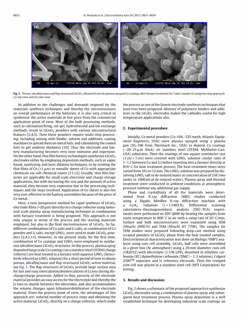
9852 N. Pentyala et al. / Electrochimica Acta 56 (2011) 9851– 9859
F praye(
mosasmfimftOebtctamnvC
etwoedpdcsdcfpsfcmLtmaa
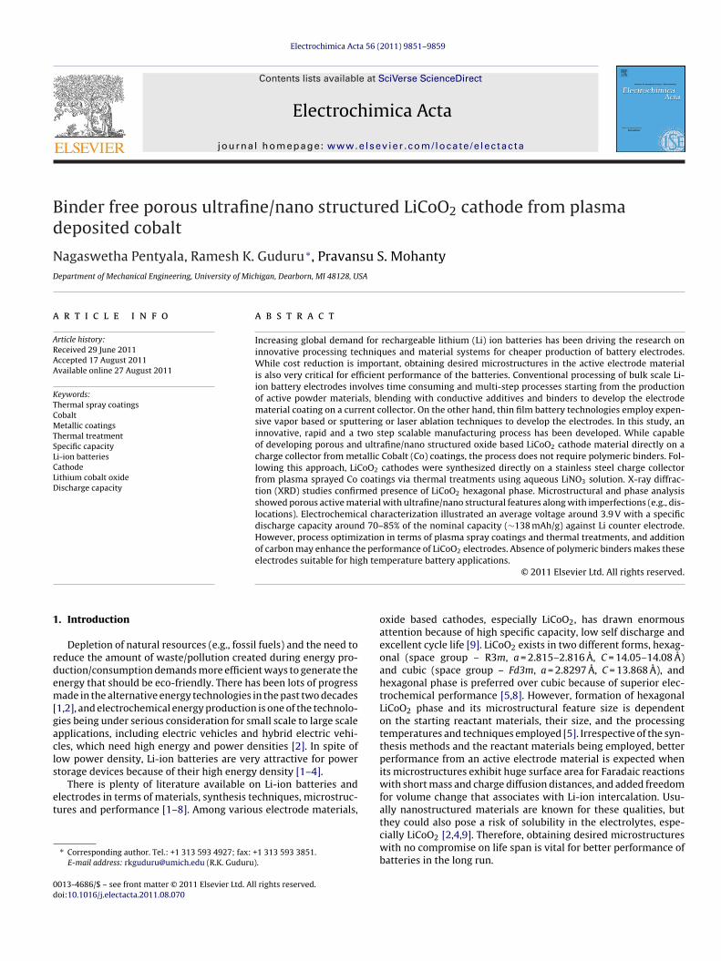
ig. 1. Porous, ultrafine/nano and flap structured LiCoO2 obtained from the plasma sa) top view and (b) side view.
In addition to the challenges and demands imposed by theaterials synthesis techniques and thereby the microstructures
n overall performance of the batteries, it is also very critical toynthesize the active materials at low price from the commercialpplication point of view. Most of the bulk processing methods,uch as calcination/firing, sol–gel, hydrothermal and ion exchangeethods, result in LiCoO2 powders with various microstructural
eatures [2,4,5]. Then these powders require multi-step process-ng, including mixing with binder, solvent and additives, coating
achines to spread them on metal foils, and calendaring the coatedoils to get uniform thickness [10]. Thus the electrode and bat-ery manufacturing becomes very time intensive and expensive.n the other hand, thin film battery technologies synthesize LiCoO2lectrodes either by employing deposition methods, such as vaporased, sputtering, and laser ablation techniques, or by treating thehin films of Co (<1 �m) or metallic sheets of Co with appropriatehemicals via soft chemical routes [11,12]. Usually, thin film bat-eries are applicable for small scale electronic and charge storagepplications, but with increasing the size and the amount of activeaterial, they become very expensive due to the processing tech-
iques and the steps involved. Application of Co sheets is also notery cost-effective in the battery assemblies because of the price ofo metal.
Here, a new inexpensive method for rapid synthesis of LiCoO2lectrode films (>20 �m) directly on a charge collector using indus-rial scale plasma spray manufacturing technique in combinationith furnace treatment is being proposed. This approach is not
nly unique in terms of the process and the starting materialsmployed, but also in the final microstructures of LiCoO2. So far,ifferent combinations of Co salts and Li salts, or combination of Coowder and Li salts, except LiNO3, were used to make LiCoO2 pow-ers [2,4,5,13]. However, in the present study, for the first time,ombination of Co coatings and LiNO3 were employed to synthe-ize ultrafine/nano LiCoO2 structures. In this process, plasma sprayeposited large scale Co coatings (on a stainless steel (SS304) chargeollector) are heat treated in a furnace with aqueous LiNO3 (hence-orth referred as LiNO3 solution) for a short period of time to obtainorous, ultrafine/nano and flap structured LiCoO2 active material,ee Fig. 1. The flap structures of LiCoO2 provide large surface areaor fast and easy intercalation/deintercalation of Li ions during dis-harge/charge processes. Added to that, porosity of the electrodeaterial provides an easy access for the electrolyte and thereby the
i ions to shuttle between the electrodes, and also accommodates
he volume changes upon lithiation/delithiation of the electrodeaterial. From the process point of view, the advantages of thispproach are; reduced number of process steps and obtaining thective material, LiCoO2, directly on a charge collector, which make
d Co coatings after furnace treatment for 5 min (sample A) using two step approach:
the process as one of the fastest electrode synthesis techniques thathave ever been proposed. Absence of polymeric binders and addi-tives in the LiCoO2 electrodes makes the cathodes useful for hightemperature applications also.
2. Experimental procedure
Initially, Co metal powders (Co-104, -325 mesh, Atlantic Equip-ment Engineers, USA) were plasma sprayed using a plasmagun (SG-100 from Thermach Inc., USA) to deposit Co coatings(∼20–25 �m thick) on stainless steel (SS304, McMaster-Carr,USA) substrates. Then the coatings of one square centimeter size(1 cm × 1 cm) were covered with LiNO3 solution (molar ratio of1–1.2 between Co and Li) before inserting into a furnace directly at810 ◦C for heat treatment process. The heat treatment times werevaried from 10 s to 12 min. The LiNO3 solution was prepared by dis-solving LiNO3 salt in de-ionized water at concentration of 2 M (twomoles in 1000 ml of de-ionized water). Plasma spray and thermaltreatment were conducted in ambient conditions at atmosphericpressure without any additional gas supply.
Phase and crystallinity of all the materials were deter-mined from X-ray diffraction (XRD) studies conductedusing a Rigaku Miniflex X-ray diffraction machine witha Cu K� radiation (� = 1.5402 A). Differential scanningcalorimtery–thermogravimteric analysis (DSC–TGA) experi-ments were performed on SDT Q600 by heating the samples fromroom temperature to 800 ◦C in air with a ramp rate of 20 ◦C/min.Surface and bulk microstructures were examined using SEM(Hitachi 2600-N) and TEM (Hitachi HT 7700). The samples forTEM studies were prepared following drop-cast method usingscraped powders of LiCoO2 phase from the heat treated samples.Electrochemical characterization was done on Biologic VMP3 ana-lyzer using coin cell assembly. LiCoO2 half cells were assembledin a glove box (Ar atmosphere) using a 20 mm diameter coin cell(CR2032) with electrolyte (1.5 M LiPF6 dissolved in ethylene car-bonate (EC):dymethylene carbonate (DMC) – 1:2 solution), Celgard2500TM separator and Li reference electrode. Then the crimpedcoin cell was placed in a stainless steel cell (MTI Corporation) fortesting.
3. Results and discussion
Fig. 2 shows a schematic of the proposed approach to synthesizeLiCoO2 electrodes using a combination of plasma spray and subse-quent heat treatment process. Plasma spray deposition is a wellestablished technique for developing industrial scale coatings on
N. Pentyala et al. / Electrochimica Acta 56 (2011) 9851– 9859 9853
tteries
laauptdsdpibsfLttpn
Fw
Fig. 2. Schematic for two step synthesis of LiCoO2 cathodes for Li-ion ba
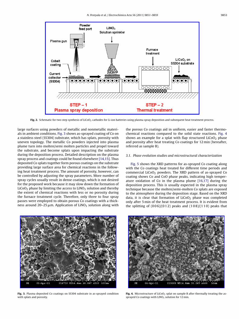
arge surfaces using powders of metallic and nonmetallic materi-ls in ambient conditions. Fig. 3 shows as-sprayed coating of Co on
stainless steel (SS304) substrate, which has splats, porosity withneven topology. The metallic Co powders injected into plasmalume turn into molten/semi molten particles and propel towardhe substrate, and become splats upon impacting the substrateuring the deposition process. Detailed description on the plasmapray process and coatings could be found elsewhere [14,15]. Thuseposited Co splats together form porous coatings on the substrateroviding large surface area for chemical reactions in the follow-
ng heat treatment process. The amount of porosity, however, cane controlled by adjusting the spray parameters. More number ofpray cycles usually result in dense coatings, which is not desiredor the proposed work because it may slow down the formation ofiCoO2 phase by limiting the access to LiNO3 solution and therebyhe extent of chemical reactions with less or no porosity during
he furnace treatment cycle. Therefore, only three to four sprayasses were employed to obtain porous Co coatings with a thick-ess around 20–25 �m. Application of LiNO3 solution along withig. 3. Plasma deposited Co coatings on SS304 substrate in as-sprayed conditionith splats and porosity.
using plasma spray deposition and subsequent heat treatment process.
the porous Co coatings aid in uniform, easier and faster thermo-chemical reactions compared to the solid state reactions. Fig. 4shows an example for a splat with flap structured LiCoO2 phaseand porosity after heat treating Co coatings for 12 min (hereafter,referred as sample B).
3.1. Phase evolution studies and microstructural characterization
Fig. 5 shows the XRD patterns for as-sprayed Co coating alongwith the Co coatings heat treated for different time periods andcommercial LiCoO2 powders. The XRD pattern of as-sprayed Cocoating shows Co and CoO phase peaks, indicating high temper-ature oxidation of Co in the plasma plume [16,17] during thedeposition process. This is usually expected in the plasma spraytechnique because the molten/semi-molten Co splats are exposed
to the atmosphere during the deposition stage. Based on the XRDdata, it is clear that formation of LiCoO2 phase was completedonly after 5 min of the heat treatment process. It is evident fromthe splitting of (0 0 6)/(0 1 2) peaks and (1 0 8)/(1 1 0) peaks thatFig. 4. Microstructure of LiCoO2 splat on sample B after thermally treating the as-sprayed Co coatings with LiNO3 solution for 12 min.
9854 N. Pentyala et al. / Electrochimica Acta 56 (2011) 9851– 9859
15 25 35 45 55 65 75Angle / 2θ
Inte
nsity
/ A
.U.
As-sprayed Co coa�ng
Commercial LiCoO2
1 m 30 s
3 mA - 5 mB - 12 m
#
^
*
*
*
*
**
* * *
*
C - 12 m - a�er cycling
#
@
@@ #
^
+^
+ +
* LiCoO2
@ CoOCo
Li6CoO4
Li2O#^+
@
(003
)4
(104
)4
(101
)4(006
)4
(015
)4
(107
)4
(108
)4(110
)4
(113
)4
(012
)4
+
64 66 68
A
B
(108
)4(1
10)4
C
36 38 40
A
B(0
06)4
(101
)4
(012
)4
C
F eat trB n 36–
tsvpappLmcaptt
2
3
L
L
ta(lt
Fmw
ig. 5. X-ray diffraction patterns for as-sprayed Co coatings along with the samples h) and 12 min sample after cycling (sample C). Zoom in views for the peaks betwee
he LiCoO2 obtained was predominantly hexagonal phase with apace group R3m [18–20]. Although, the intensity of (0 0 6) peak isery less in 5 min sample (henceforth referred as sample A) com-ared to the 12 min sample, separation of (1 0 8) and (1 1 0) peaks ispparent in both the samples. Also, the highest intensity for (1 0 4)eak for LiCoO2 in the heat treated samples could be noticed com-ared to the highest intensity for (0 0 3) peak in the commercialiCoO2 powders, and this could be due to specific orientation of theicrostructures of LiCoO2 phase in the heat treated samples. The Co
oating heat treated for 1 min and 30 s shows extra peaks for Li2Ond Li6CoO4 phases, whereas 3 min sample shows only one Li2Oeak. From the literature [5,17,21–25] as well as present observa-ions, following chemical reactions could be expected to occur inwo stages during the heat treatment process of Co coatings.
1st stage
LiNO3 → Li2O + 2NO2(g) + 1/2O2(g) (1a)
Co + 2O2(g) → Co3O4 (1b)
2nd stage
i2O + 2/3Co3O4 + 1/6O2(g) → 2LiCoO2 (2a)
i2O + CoO → Li6CoO4 → LiCoO2 (2b)
We believe that conversion of Li6CoO4 into LiCoO2 could be dueo further diffusion of Li into the Co coatings along with some
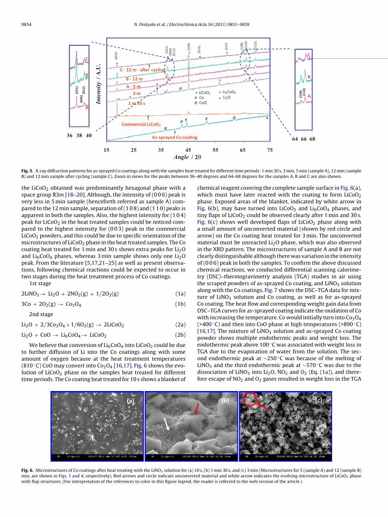
mount of oxygen because at the heat treatment temperatures810 ◦C) CoO may convert into Co3O4 [16,17]. Fig. 6 shows the evo-ution of LiCoO2 phase on the samples heat treated for differentime periods. The Co coating heat treated for 10 s shows a blanket ofig. 6. Microstructures of Co coatings after heat treating with the LiNO3 solution for (a) 10in, are shown in Figs. 1 and 4, respectively). Red arrows and circle indicate unconverteith flap structures. (For interpretation of the references to color in this figure legend, th
eated for different time periods: 1 min 30 s, 3 min, 5 min (sample A), 12 min (sample40 degrees and 64–68 degrees for the samples A, B and C are also shown.
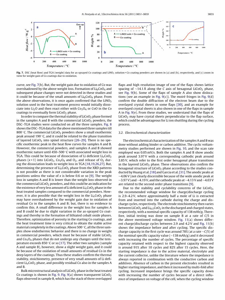
chemical reagent covering the complete sample surface in Fig. 6(a),which must have later reacted with the coating to form LiCoO2phase. Exposed areas of the blanket, indicated by white arrow inFig. 6(b), may have turned into LiCoO2 and Li6CoO4 phases, andtiny flaps of LiCoO2 could be observed clearly after 1 min and 30 s.Fig. 6(c) shows well developed flaps of LiCoO2 phase along witha small amount of unconverted material (shown by red circle andarrow) on the Co coating heat treated for 3 min. The unconvertedmaterial must be unreacted Li2O phase, which was also observedin the XRD pattern. The microstructures of sample A and B are notclearly distinguishable although there was variation in the intensityof (0 0 6) peak in both the samples. To confirm the above discussedchemical reactions, we conducted differential scanning calorime-try (DSC)–thermogravimetry analysis (TGA) studies in air usingthe scraped powders of as-sprayed Co coating, and LiNO3 solutionalong with the Co coatings. Fig. 7 shows the DSC–TGA data for mix-ture of LiNO3 solution and Co coating, as well as for as-sprayedCo coating. The heat flow and corresponding weight gain data fromDSC–TGA curves for as-sprayed coating indicate the oxidation of Cowith increasing the temperature. Co would initially turn into Co3O4(>400 ◦C) and then into CoO phase at high temperatures (>890 ◦C)[16,17]. The mixture of LiNO3 solution and as-sprayed Co coatingpowder shows multiple endothermic peaks and weight loss. Theendothermic peak above 100 ◦C was associated with weight loss inTGA due to the evaporation of water from the solution. The sec-
ond endothermic peak at ∼250 ◦C was because of the melting ofLiNO3 and the third endothermic peak at ∼570 ◦C was due to thedissociation of LiNO3 into Li2O, NO2 and O2 (Eq. (1a)), and there-fore escape of NO2 and O2 gases resulted in weight loss in the TGAs, (b) 1 min 30 s, and (c) 3 min (Microstructures for 5 (sample A) and 12 (sample B)d material and white arrow indicates the evolving microstructure of LiCoO2 phasee reader is referred to the web version of the article.)
N. Pentyala et al. / Electrochimica Acta 56 (2011) 9851– 9859 9855
F 3 soluv
cositscc
iDs8pocHeTpidipltthemrcaiTtmpiapAbdsca
Cfl
ig. 7. DSC (heat flow) and TGA (weight) data for as-sprayed Co coatings and LiNOiew for weight gain of Co coatings due to oxidation.
urve, see Fig. 7(b). But, the weight gain due to oxidation of Co wasvershadowed by the above weight loss. Formation of Li6CoO4 andubsequent phase changes were not detected in these studies andt could be because of the small amounts of Li6CoO4 phase. Fromhe above observations, it is once again confirmed that the LiNO3olution used in the heat treatment process would initially disso-iate into Li2O and then react either with Co3O4 or CoO in the Cooatings to eventually form LiCoO2 phase.
In order to compare the thermal stability of LiCoO2 phase formedn the samples A and B with the commercial LiCoO2 powders, theSC–TGA studies were conducted on all the three samples. Fig. 8
hows the DSC–TGA data for the above mentioned three samples till00 ◦C. The commercial LiCoO2 powders show a small exothermiceak around 190 ◦C, and it could be related to the phase transitionf layered LiCoO2 into spinel structure [26–29]. There is no spe-ific exothermic peak in the heat flow curves for samples A and B.owever, the commercial powders, and samples A and B showedxothermic nature until 450–500 ◦C with associated weight loss inGA. This could be because of dissociation of Li deficient LixCoO2hases (x < 1) into LiCoO2, Co3O4 and O2, and release of O2 dur-
ng the dissociation leads to weight loss in TGA [18,19,26,27]. But,etermining the presence of LixCoO2 phase from the XRD patterns
s not possible as there is not considerable variation in the peakositions unless the value of x is below 0.6 or so [9]. The weight
oss in samples A and B is lower than the weight loss observed inhe commercial LiCoO2 powders, and this could be an indication forhe existence of very less amount of Li deficient LixCoO2 phase in theeat treated samples compared to the commercial powders. How-ver, it is also possible that the weight loss in the LixCoO2 phaseay have overshadowed by the weight gain due to oxidation of
esidual Co in the samples A and B; but, there is no evidence toonfirm this. A small difference in the weight loss for samples And B could be due to slight variation in the as-sprayed Co coat-ngs and thereby in the formation of lithiated cobalt oxide phases.herefore, optimization of porosity in the starting Co coatings, andhe heat treatment time is very critical to obtain the stable active
aterial completely in the coatings. Above 500 ◦C, all the three sam-les show endothermic behavior and there is no change in weight
n commercial powders, which must be because of stable LiCoO2nd Co3O4 phases that do not undergo any changes until the tem-erature exceeds 850 ◦C or so [17]. The other two samples (sample
and sample B), however, show a slight weight gain, and it coulde because of the oxidation of small amounts of residual Co in theeep layers of the coatings. Thus these studies confirm the thermaltability, stoichiometry, presence of very small amounts of Li defi-ient LixCoO2 phase, and possibly residual Co also in the samples A
nd B.Bulk microstructural analysis of LiCoO2 phase in the heat treatedo coatings is shown in Fig. 9. Fig. 9(a) shows transparent LiCoO2aps observed in sample B, which has the stack of three overlapped
tion + Co coating powders are shown in (a) and (b), respectively, and (c) zoom in
flaps and high resolution image of one of the flaps shows latticespacing of ∼14.1 A along the C axis of hexagonal LiCoO2 phase,see Fig. 9(b). Some of the flaps of sample A also show disloca-tions (see an example in Fig. 9(c)). The moiré fringes in Fig. 9(d)confirm the double diffraction of the electron beam due to theoverlayed crystal sheets in some flaps [30], and an example foroverlayed crystal sheets is also shown in one of the flaps in sampleA in Fig. 9(e). From these studies, we understand that the flaps ofLiCoO2 may have crystal sheets perpendicular to the flap surface,which could be advantageous for Li ion shuttling during the cyclingprocess.
3.2. Electrochemical characterization
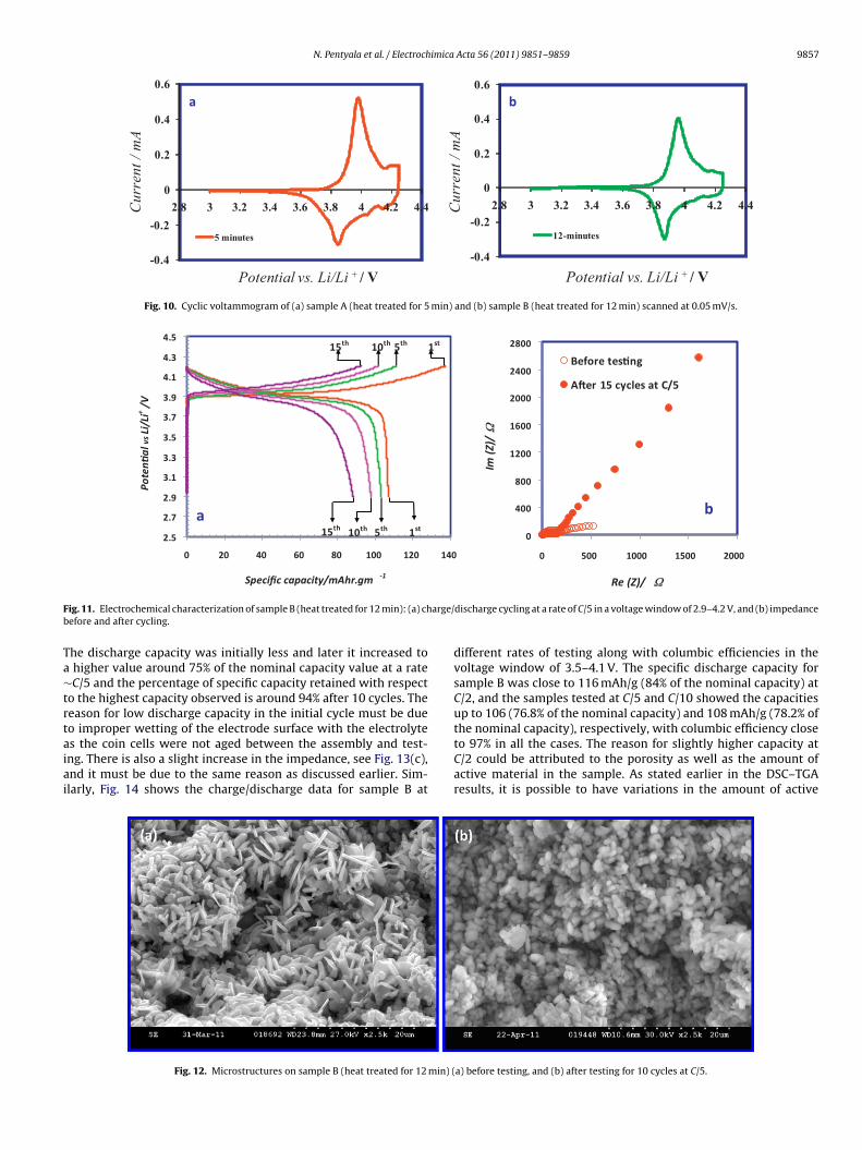
The electrochemical characterization of the samples A and B wasdone without adding binder or carbon additive. The cyclic voltam-metry studies performed are shown in Fig. 10, and the scan rateemployed was 0.05 mV/s. Both the samples A and B show anodicpeak around 3.97 V with a corresponding cathodic peak around3.85 V, which refer to the first order hexagonal phase transitionsin the layered LiCoO2 phase. These observations also confirm thehexagonal structure of LiCoO2 phase according to the studies con-ducted by Huang et al. [18] and Garcia et al. [31]. The anodic peaks at∼4.06 V (not clearly discernible because of the wide anodic peak at∼3.97 V) and ∼4.19 V, and the cathodic peaks at ∼4.13 V and ∼4.03 Vare related to the second order phase transitions [9].
Due to the stability and cyclability concerns of the LiCoO2,the recommended voltage window for charge/discharge cyclingis 2.9–4.2 V, where approximately half a mole of Li is extractedfrom and inserted into the cathode during the charge and dis-charge cycles, respectively. The electrode stoichiometry then variesbetween LiCoO2 and Li0.5CoO2 in the discharged and charged states,respectively, with a nominal specific capacity of 138 mAh/g. There-fore, initial testing was done on sample B at a rate of C/5 inthe above mentioned voltage window. Fig. 11(a) shows differ-ent charge/discharge cycles between 2.9 and 4.2 V and Fig. 11(b)shows the impedance before and after cycling. The specific dis-charge capacity in the first cycle was around 78% (at a rate ∼C/5) ofthe nominal specific capacity value (∼138 mAh/g) and it decreasedwith increasing the number of cycles. The percentage of specificcapacity retained with respect to the highest capacity observedis around 91% after 10 cycles and 82% after 15 cycles. Here, thestarting impedance is due to the active material, electrolyte andthe current collector, unlike the literature where the impedance isalways reported in combination with the conductive carbon andadditives. Absence of carbon in the present electrodes resulted in
higher starting impedance, and then it increased by multi-fold aftercycling. Increased impedance brings the specific capacity downwith increasing the number of cycles because of a direct influ-ence of impedance on voltage of the cell, when the cycling window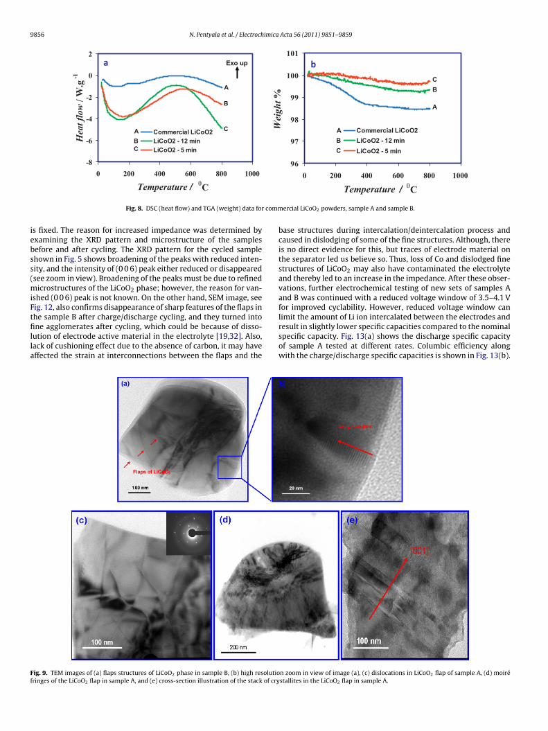
9856 N. Pentyala et al. / Electrochimica Acta 56 (2011) 9851– 9859
-8
-6
-4
-2
0
2
10008006004002000
Temperature / 0C
Hea
t flo
w /
W.g
-1
Comm ercial LiCoO2LiCoO2 - 12 minLiCoO2 - 5 min
A
B
C
CBA
Exo up
96
97
98
99
100
101
100080060040020000
Wei
ght %
Commercial LiCoO2LiCoO2 - 12 minLiCoO2 - 5 min
A
BC
ABC
a b
comm
iebss(miFtfilla
Ff
Fig. 8. DSC (heat flow) and TGA (weight) data for
s fixed. The reason for increased impedance was determined byxamining the XRD pattern and microstructure of the samplesefore and after cycling. The XRD pattern for the cycled samplehown in Fig. 5 shows broadening of the peaks with reduced inten-ity, and the intensity of (0 0 6) peak either reduced or disappearedsee zoom in view). Broadening of the peaks must be due to refined
icrostructures of the LiCoO2 phase; however, the reason for van-shed (0 0 6) peak is not known. On the other hand, SEM image, seeig. 12, also confirms disappearance of sharp features of the flaps inhe sample B after charge/discharge cycling, and they turned into
ne agglomerates after cycling, which could be because of disso-ution of electrode active material in the electrolyte [19,32]. Also,ack of cushioning effect due to the absence of carbon, it may haveffected the strain at interconnections between the flaps and the
ig. 9. TEM images of (a) flaps structures of LiCoO2 phase in sample B, (b) high resolutioringes of the LiCoO2 flap in sample A, and (e) cross-section illustration of the stack of cry
Temperature / C
ercial LiCoO2 powders, sample A and sample B.
base structures during intercalation/deintercalation process andcaused in dislodging of some of the fine structures. Although, thereis no direct evidence for this, but traces of electrode material onthe separator led us believe so. Thus, loss of Co and dislodged finestructures of LiCoO2 may also have contaminated the electrolyteand thereby led to an increase in the impedance. After these obser-vations, further electrochemical testing of new sets of samples Aand B was continued with a reduced voltage window of 3.5–4.1 Vfor improved cyclability. However, reduced voltage window canlimit the amount of Li ion intercalated between the electrodes and
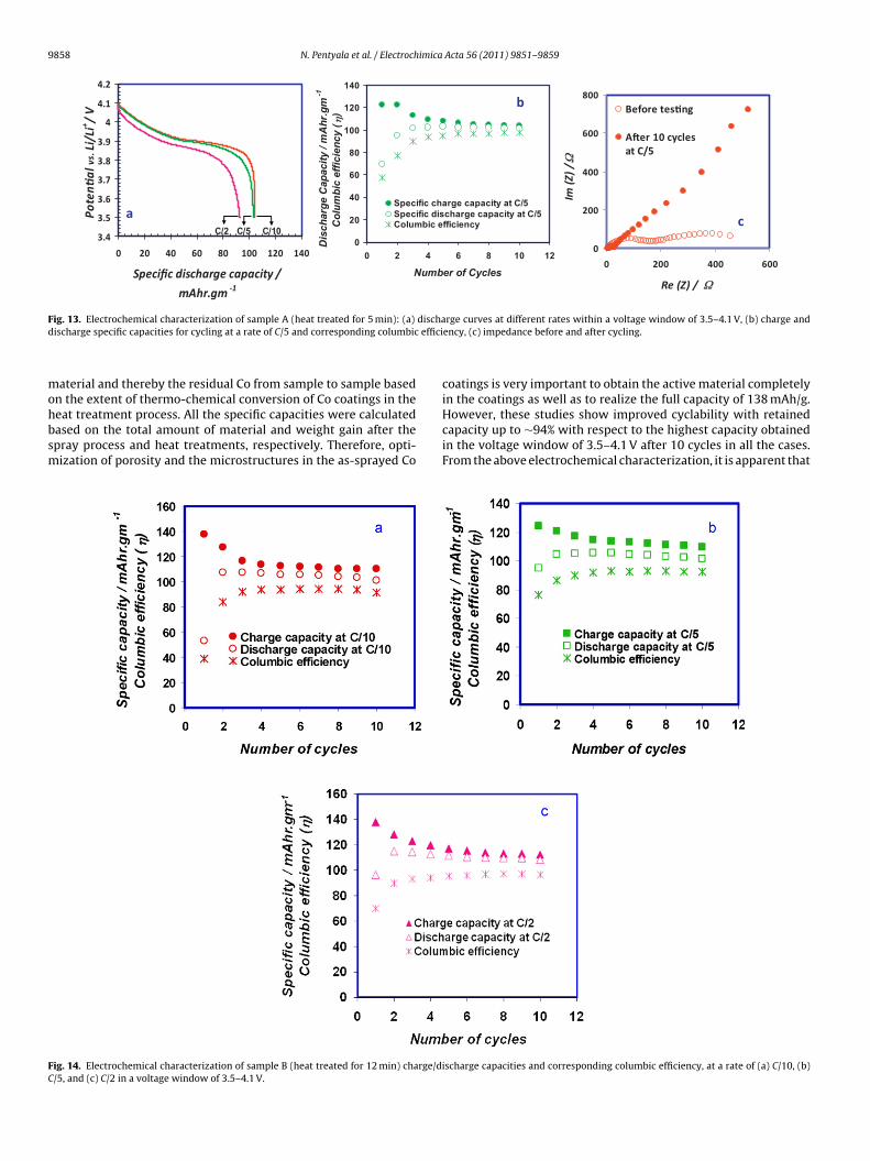
result in slightly lower specific capacities compared to the nominalspecific capacity. Fig. 13(a) shows the discharge specific capacityof sample A tested at different rates. Columbic efficiency alongwith the charge/discharge specific capacities is shown in Fig. 13(b).n zoom in view of image (a), (c) dislocations in LiCoO2 flap of sample A, (d) moiréstallites in the LiCoO2 flap in sample A.
N. Pentyala et al. / Electrochimica Acta 56 (2011) 9851– 9859 9857
-0.4
-0.2
0
0.2
0.4
0.6
4.44.243.83.63.43.232.8
Pote nti al vs. Li/L i + / V
5 minutes
-0.4
-0.2
0
0.2
0.4
0.6
4.44.243.83.63.43.232.8
Pote ntial vs. Li/L i + / V
12-minutes
a b
Cur
rent
/ m
A
Cur
rent
/ m
A
Fig. 10. Cyclic voltammogram of (a) sample A (heat treated for 5 min) and (b) sample B (heat treated for 12 min) scanned at 0.05 mV/s.
0
400
800
1200
1600
2000
2400
2800
2000150010005000
Re (Z )/ Ω
Im(Z)/Ω
Before tes�ng
A�er 15 cycles at C/5
b
2.5
2.7
2.9
3.1
3.3
3.5
3.7
3.9
4.1
4.3
4.5
140120100806040200
Speci fic capacity/mAhr.gm -1
Poten�
alvsLi/Li+/V
15th 10th 5th 1st
15th 10th 5th 1st
a
F arge/b
Ta∼trtaiai
ig. 11. Electrochemical characterization of sample B (heat treated for 12 min): (a) chefore and after cycling.
he discharge capacity was initially less and later it increased to higher value around 75% of the nominal capacity value at a rateC/5 and the percentage of specific capacity retained with respect
o the highest capacity observed is around 94% after 10 cycles. Theeason for low discharge capacity in the initial cycle must be dueo improper wetting of the electrode surface with the electrolyte
s the coin cells were not aged between the assembly and test-ng. There is also a slight increase in the impedance, see Fig. 13(c),nd it must be due to the same reason as discussed earlier. Sim-larly, Fig. 14 shows the charge/discharge data for sample B atFig. 12. Microstructures on sample B (heat treated for 12 min) (
discharge cycling at a rate of C/5 in a voltage window of 2.9–4.2 V, and (b) impedance
different rates of testing along with columbic efficiencies in thevoltage window of 3.5–4.1 V. The specific discharge capacity forsample B was close to 116 mAh/g (84% of the nominal capacity) atC/2, and the samples tested at C/5 and C/10 showed the capacitiesup to 106 (76.8% of the nominal capacity) and 108 mAh/g (78.2% ofthe nominal capacity), respectively, with columbic efficiency close
to 97% in all the cases. The reason for slightly higher capacity atC/2 could be attributed to the porosity as well as the amount ofactive material in the sample. As stated earlier in the DSC–TGAresults, it is possible to have variations in the amount of activea) before testing, and (b) after testing for 10 cycles at C/5.
9858 N. Pentyala et al. / Electrochimica Acta 56 (2011) 9851– 9859
0
200
400
600
800
0 200 400 600
Re (Z) / Ω
Im(Z)/Ω
Before tes� ng
A�er 10 cyclesat C/5
0
20
40
60
80
100
120
140
0 2 4 6 8 10 12
Number of Cycles
Dis
char
ge C
apac
ity /
mA
hr.g
m-1
Col
umbi
c ef
ficie
ncy
( η)
Spec ific charge capac ity at C/5Spec ific disc harge ca pac ity at C/5Columbic effi ciency
3.4
3.5
3.6
3.7
3.8
3.9
4
4.1
4.2
0 20 40 60 80 10 0 12 0 140
Specific discharge capacity /
mAhr.gm -1
Poten�
alvs.Li/Li
+ /V
C/2 C/5 C/10
a
b
c
Fig. 13. Electrochemical characterization of sample A (heat treated for 5 min): (a) discharge curves at different rates within a voltage window of 3.5–4.1 V, (b) charge andd effici
mohbsm
FC
ischarge specific capacities for cycling at a rate of C/5 and corresponding columbic
aterial and thereby the residual Co from sample to sample basedn the extent of thermo-chemical conversion of Co coatings in the
eat treatment process. All the specific capacities were calculatedased on the total amount of material and weight gain after thepray process and heat treatments, respectively. Therefore, opti-ization of porosity and the microstructures in the as-sprayed Coig. 14. Electrochemical characterization of sample B (heat treated for 12 min) charge/d/5, and (c) C/2 in a voltage window of 3.5–4.1 V.
ency, (c) impedance before and after cycling.
coatings is very important to obtain the active material completelyin the coatings as well as to realize the full capacity of 138 mAh/g.
However, these studies show improved cyclability with retainedcapacity up to ∼94% with respect to the highest capacity obtainedin the voltage window of 3.5–4.1 V after 10 cycles in all the cases.From the above electrochemical characterization, it is apparent thatischarge capacities and corresponding columbic efficiency, at a rate of (a) C/10, (b)
imica
toimadhpl[
4
odsttltDLpeiimtvt(slsb
A
v
[
[
[[
[
[[
[[
[
[
[[
[[[
[[
[
[[
N. Pentyala et al. / Electroch
here is not much difference between samples A and B in termsf performance and cyclability. Limited specific discharge capac-ty of our materials could be due to high impedance of the active
aterial and voltage window chosen for cycling. In addition, welso expect some residual stresses in the as deposited Co coatingsue to rapid cooling of the deposited material and these may notave relieved completely during the subsequent heat treatmentrocess. Strained structures may not facilitate the Li-ion interca-
ation or diffusion as easily as the strain free structures could do33].
. Conclusions
In summary, here we have demonstrated successful processingf binder free, porous ultrafine/nanostructured LiCoO2 cathodesirectly on charge collectors with the application of industrialcale thermal spray technique in combination with rapid thermalreatment. The heat treatment of Co coatings with LiNO3 solu-ion resulted in flap structured LiCoO2 phase, which could providearge surface area as well as reduced distances for ionic and chargeransport during Li ion intercalation and deintercalation process.SC and electrochemical characterization confirm the hexagonaliCoO2 phase in the active material. Cyclability data indicatedossible dissolution and dislodging of the active material in thelectrolyte and thereby resulted in lower capacities with increasen the impedance with the number of cycles. Process optimizationn terms of porosity of the Co coatings and the thermal treatment
ay also be helpful to obtain the discharge capacities close tohe nominal specific capacity value (138 mAh/g). Although reducedoltage window indicated improvement in the performance, addi-ion of carbon and coating of flap structures with oxide materialse.g., ZrO2) may enhance the overall performance. Thus the twotage synthesis of fine structured LiCoO2 directly on charge col-ector with the application of well established industrial thermalpray technique may be economical for commercial production ofatteries.
cknowledgement
This research was supported by OVPR Grant # U031406 (Uni-ersity of Michigan, Ann Arbor).
[
[[
Acta 56 (2011) 9851– 9859 9859
References
[1] C. Liu, F. Li, L.-P. Ma, H.-M. Cheng, Adv. Mater. 22 (2010) E28.[2] M. Stanley Whittingham, Chem. Rev. 104 (2004) 4271.[3] J.-M. Tarascon, M. Armand, Nature 414 (2001) 360.[4] Y.-G. Guo, J.-S. Hu, L.-J Wan, Adv. Mater. 20 (2008) 2878.[5] E. Antolini, Solid State Ionics 170 (2004) 159.[6] R. Alcantara, P. Lavela, J.L. Tirado, E. Zhecheva, R. Stoyanova, J. Solid State Elec-
trochem. 3 (1999) 121.[7] K. Mizushima, P.C. Jones, P.J. Wiseman, J.B. Goodenough, Mater. Res. Bull. 15
(1980) 783.[8] R.J. Gummow, D.C. Liles, M.M Thackeray, Mater. Res. Bull. 28 (1993) 235.[9] G.A. Nazri, G. Pistoia, Lithium Batteries Science and Technology, Springer,
2009.10] L. Gaines, R. Cuenca, Center for Transportation Research Argonne
National Laboratory, United States Department of Energy Report,www.transportation.anl.gov/pdfs/TA/149.pdf, 2000.
11] H. Sato, D. Takahashi, T. Nishina, I. Uchida, J. Power Sources 68 (1997)540.
12] K.-S. Han, S.-W. Song, M. Yoshimura, Chem. Mater. 10 (1998) 2183.13] V. Berbenni, C. Milanese, G. Bruni, A. Marini, Mater. Chem. Phys. 100 (2006)
251.14] L. Pawlowski, The Science and Engineering of Thermal Spray Coatings, John
Wiley & Sons, 2008.15] H. Herman, S. Sampath, R. McCune, MRS Bull. 25 (2000) 17.16] M. Lenglet, J. Lopitaux, L. Terrier, P. Chartier, J.F. Koenig, P. Nkeng, G. Poillerat,
J. Phys. III 3 (1993) 477.17] E. Antolini, M. Ferretti, J. Solid State Chem. 117 (1995) 1.18] B. Huang, Y.-I. Jang, Y.-M. Chiang, D.R. Sadoway, J. Appl. Electrochem. 28 (1998)
1365.19] G.G. Amatucci, J.M. Tarascon, L.C. Klein, Solid State Ionics 83 (1996)
167.20] G.G. Amatucci, J.M. Tarascon, D. Larcher, L.C. Klein, Solid State Ionics 84 (1996)
169.21] E. Antolini, L. Giorgi, M. Carewska, J. Mater. Sci. Lett. 18 (1999) 325.22] D. Carlier, I. Saadoune, L. Croguennec, M. Menetrier, E. Saurd, C. Delmas, Solid
State Ionics 144 (2001) 263.23] S. Rodrigues, N. Munichandraiah, A.K. Shukla, J. Power Sources 102 (2001) 322.24] M.N. Obrovac, O. Mao, J.R. Dahn, Solid State Ionics 112 (1998) 9.25] N.V. Kosova, V.F. Anufrienko, T.V. Larina, A. Rougier, L. Aymard, J.M. Tarascon,
J. Solid State Chem. 165 (2002) 56.26] R.J. Gummow, M.M. Thackeray, Mat. Res. Bull. 27 (1992) 327.27] Y.-B. He, Z.-Y. Tang, Q.-S. Song, X. Hui, X. Qiang, Y.-G. Liu, G.-W. Ling, Ther-
mochem. Acta 480 (2008) 15.28] A. Velucham, C.-H. Doh, D.-H. Kim, J.-H. Lee, H.-M. Shin, B.-S. Jin, H.-S. Kim, S.-I.
Moon, J. Power Sources 189 (2009) 855.29] Y. Baba, S. Okada, J.-i. Yamaki, Solid State Ionics 148 (2002) 311.30] H. Gabrisch, R. Yazami, B. Fultz, J. Power Sources 119–121 (2004) 674.
31] B. Garcia, J. Farcy, J.P. Pereira-Ramos, J. Perichon, N. Baffler, J. Power Sources 54(1995) 373.32] R. Yazamia, R. Ozawaa, H. Gabrisch, B. Fultz, Electrochem. Acta 50 (2004) 385.33] T. Brezesinski, J. Wang, R. Senter, K. Brezesinski, B. Dunn, S.H. Tolbert, ACS Nano
2 (2010) 967.
Related Documents