Binary Logic Diagrams for Process Operations Reaffirmed 13 July 1992 ANSI/ISA–S5.2–1976 (R1992) AMERICAN NATIONAL STANDARD No reproduction or networking permitted without license from IHS --``,`,`,,,,`,,,,`,```,``````,`-`-`,,`,,`,`,,`---

Welcome message from author
This document is posted to help you gain knowledge. Please leave a comment to let me know what you think about it! Share it to your friends and learn new things together.
Transcript
Reaffirm
ANSI/IS
A M E R I C A N N A T I O N A L S T A N D A R D
Copyright The Instrumentation, Systems, and Automation Society Provided by IHS under license with ISA No reproduction or networking permitted without license from IHS
,,,,`,,,,`,```,``````,`-`-`,,`,,`,`,,`---
A–S5.2–1976 (R1992)
Binary Logic Diagrams forProcess Operations
--``,`,`
ed 13 July 1992
Licensee=Technip Abu Dabhi/5931917101 Not for Resale, 02/12/2006 06:01:14 MST
Copyright 1992 by the Instrument Society of America. All rights reserved. Printed in the UnitedStates of America. No part of this publication may be reproduced, stored in a retrieval system, ortransmitted in any form or by any means (electronic, mechanical, photocopying, recording, orotherwise), without the prior written permission of the publisher.
ISA67 Alexander DriveP.O. Box 12277Research Triangle Park, North Carolina 27709
ISA-S5.2 — Binary Logic Diagrams for Process Operations
ISBN 0-87664-331-4
Copyright The Instrumentation, Systems, and Automation Society Provided by IHS under license with ISA Licensee=Technip Abu Dabhi/5931917101
Not for Resale, 02/12/2006 06:01:14 MSTNo reproduction or networking permitted without license from IHS
--``,`,`,,,,`,,,,`,```,``````,`-`-`,,`,,`,`,,`---
Copyright The InstrumeProvided by IHS under No reproduction or netw
--``,`,`,,,,`,,,,`,```,``````,`-`-`,,`,,`,`,,`---
Preface
This preface is included for informational purposes and is not part of Standard ISA-S5.2.
This Standard has been prepared as a part of the service of ISA toward a goal of uniformity in the field of instrumentation. To be of real value, this document should not be static, but should be subject to periodic review. Toward this end, the Society welcomes all comments and criticisms, and asks that they be addressed to the Secretary, Standards and Practices Board, ISA, 67 Alexander Drive, P.O. Box 12277, Research Triangle Park, NC 27709, Telephone (919) 549-8411, e-mail: [email protected].
The ISA Standards and Practices Department is aware of the growing need for attention to the metric system of units in general, and the International System of Units (SI) in particular, in the preparation of instrumentation standards. The Department is further aware of the benefits to USA users of ISA Standards of incorporating suitable references to the SI (and the metric system) in their business and professional dealings with other countries. Toward this end this Department will endeavor to introduce SI-acceptable metric units in all new and revised standards to the greatest extent possible. The Metric Practice Guide, which has been published by the American Society for Testing and Materials as ANSI designation Z210.1 (ASTM E380-76, IEEE Std. 286-1975), and further revisions, will be the reference guide for definitions, symbols, abbreviation, and conversion factors.
It is the Policy of ISA to encourage and welcome the participation of all concerned individuals and interests in the development of ISA Standards. Participation in the ISA Standards making process by an individual in no way constitutes endorsement by the employer of that individual of ISA or any of the Standards which ISA develops.
The system described in this Standard is intended to meet the needs of people who are concerned with the operation of process systems. The guide for the Standard was American National Standards Institute (ANSI) Standard Y32.14.1973, Graphic Symbols for Logic Diagrams, which the committee attempted to follow so far as practical for the intended users of the ISA Standard.
The Committee also referred to National Electric Manufacturers Association Standards ICS 1-102, Graphic Symbols for Logic Diagrams, whose symbols bear resemblance to those of the ANSI Standard, and ICS 1-103, Static Switching Control Devices, which may eventually be supplanted by ICS 1-102. Reference was also made to National Fluid Power Association Recommended Standard T.3.7.68.2, Graphic Symbols for Fluidic Devices and Circuits. In addition, numerous other industrial standards were reviewed.
The following people served on the 1976 SP5.2 Committee:
NAME COMPANY
George Platt, Chairman Bechtel Power CompanyEdward J. Blahut Procon Incorporated, Pacific OperationsSanford Chalfin Fluor CorporationLouis Costea Hunt-Wesson Foods, IncorporatedRussell C. Greer Bailey Meter CompanyRoy Lazar Carnation Company
ANSI/ISA-S5.2-1976 (R 1992) 3
ntation, Systems, and Automation Society license with ISA Licensee=Technip Abu Dabhi/5931917101
Not for Resale, 02/12/2006 06:01:14 MSTorking permitted without license from IHS
Copyright The InstrumeProvided by IHS under No reproduction or netw
--``,`,`,,,,`,,,,`,```,``````,`-`-`,,`,,`,`,,`---
Frank Mehle (deceased) Procon Incorporated, Pacific OperationGary L. Pierce Shell Oil CompanyChuck Simms Fisher Controls CompanyJohn Vance United Process Control SystemsRobert Woo Los Angeles Department of Water & Power
The following people served on the 1981 (reaffirmation) SP5.2 Committee:
NAME COMPANY
Russell C. Greer, Chairman Bailey Controls CompanyEdward J. Blahut Blahut Engineering, Inc.Sanford Chalfin Fluor Corporation (retired)Louis Costea Hunt-Wesson Foods, Inc.Roy Lazar Carnation CompanyGary L. Pierce Shell Oil CompanyGeorge Platt Bechtel Power CorporationCharles Simms Fisher Controls CompanyJohn Vance ComsyscoRobert Woo Los Angeles Department of Water & Power
The 1976 edition of this Standard was approved by the ISA Standards and Practices Board in November, 1975.
NAME COMPANY
W. B. Miller, Chairman Moore Products CompanyP. Bliss Pratt & Whitney Aircraft CompanyE. J. Byrne Brown & Root, Inc.W. Calder The Foxboro CompanyB. A. Christensen Continental Oil CompanyL. N. Combs E. I. du Pont de Nemours & Company (retired)R. L. Galley Bechtel Power CorporationR. G. Hand, Secretary ISAT. J. Harrison IBM CorporationT. S. Imsland Fisher Controls CompanyP. S. Lederer National Bureau of StandardsO. P. Lovett, Jr. E. I. du Pont de Nemours & CompanyE. C. Magison Honeywell, Inc.R. L. Martin Tex-A-Mation Engineering Inc.A. P. McCauley Glidden-Durkee Div. SCM CorporationT. A. Murphy The Fluor Corporation, Ltd.R. L. Nickens Reynolds Metals CompanyG. Platt Bechtel Power CorporationA. T. Upfold Polysar Ltd.K. A. Whitman Allied Chemical Corporation
4 ANSI/ISA-S5.2-1976 (R 1992)
ntation, Systems, and Automation Society license with ISA Licensee=Technip Abu Dabhi/5931917101
Not for Resale, 02/12/2006 06:01:14 MSTorking permitted without license from IHS
Copyright The InstrumeProvided by IHS under No reproduction or netw
--``,`,`,,,,`,,,,`,```,``````,`-`-`,,`,,`,`,,`---
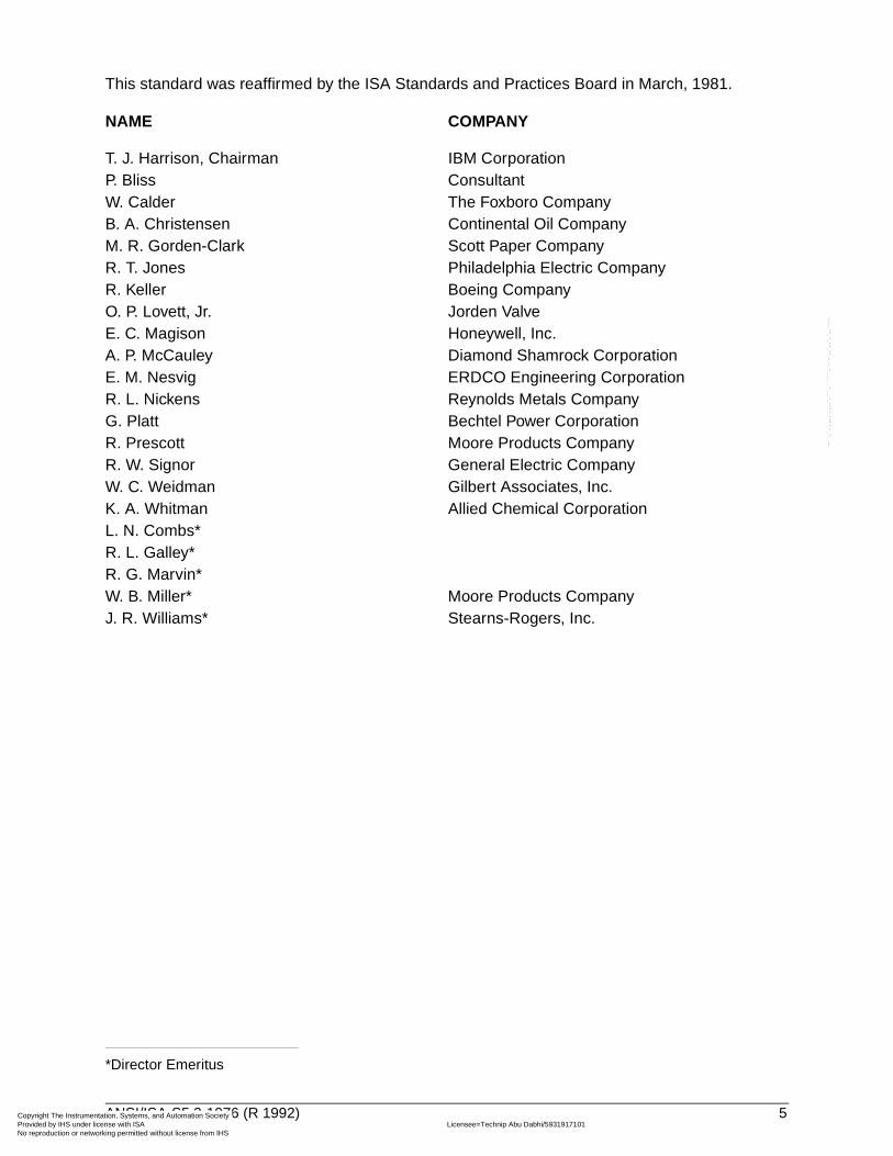
This standard was reaffirmed by the ISA Standards and Practices Board in March, 1981.
NAME COMPANY
T. J. Harrison, Chairman IBM CorporationP. Bliss ConsultantW. Calder The Foxboro CompanyB. A. Christensen Continental Oil CompanyM. R. Gorden-Clark Scott Paper CompanyR. T. Jones Philadelphia Electric CompanyR. Keller Boeing CompanyO. P. Lovett, Jr. Jorden ValveE. C. Magison Honeywell, Inc.A. P. McCauley Diamond Shamrock CorporationE. M. Nesvig ERDCO Engineering CorporationR. L. Nickens Reynolds Metals CompanyG. Platt Bechtel Power CorporationR. Prescott Moore Products CompanyR. W. Signor General Electric CompanyW. C. Weidman Gilbert Associates, Inc.K. A. Whitman Allied Chemical CorporationL. N. Combs* R. L. Galley*R. G. Marvin*W. B. Miller* Moore Products CompanyJ. R. Williams* Stearns-Rogers, Inc.
*Director Emeritus
ANSI/ISA-S5.2-1976 (R 1992) 5
ntation, Systems, and Automation Society license with ISA Licensee=Technip Abu Dabhi/5931917101
Not for Resale, 02/12/2006 06:01:14 MSTorking permitted without license from IHS

Copyright The Instrumentation, Systems, and Automation Society Provided by IHS under license with ISA Licensee=Technip Abu Dabhi/5931917101
Not for Resale, 02/12/2006 06:01:14 MSTNo reproduction or networking permitted without license from IHS
--``,`,`,,,,`,,,,`,```,``````,`-`-`,,`,,`,`,,`---
Copyright The InstrumeProvided by IHS under No reproduction or netw
Contents
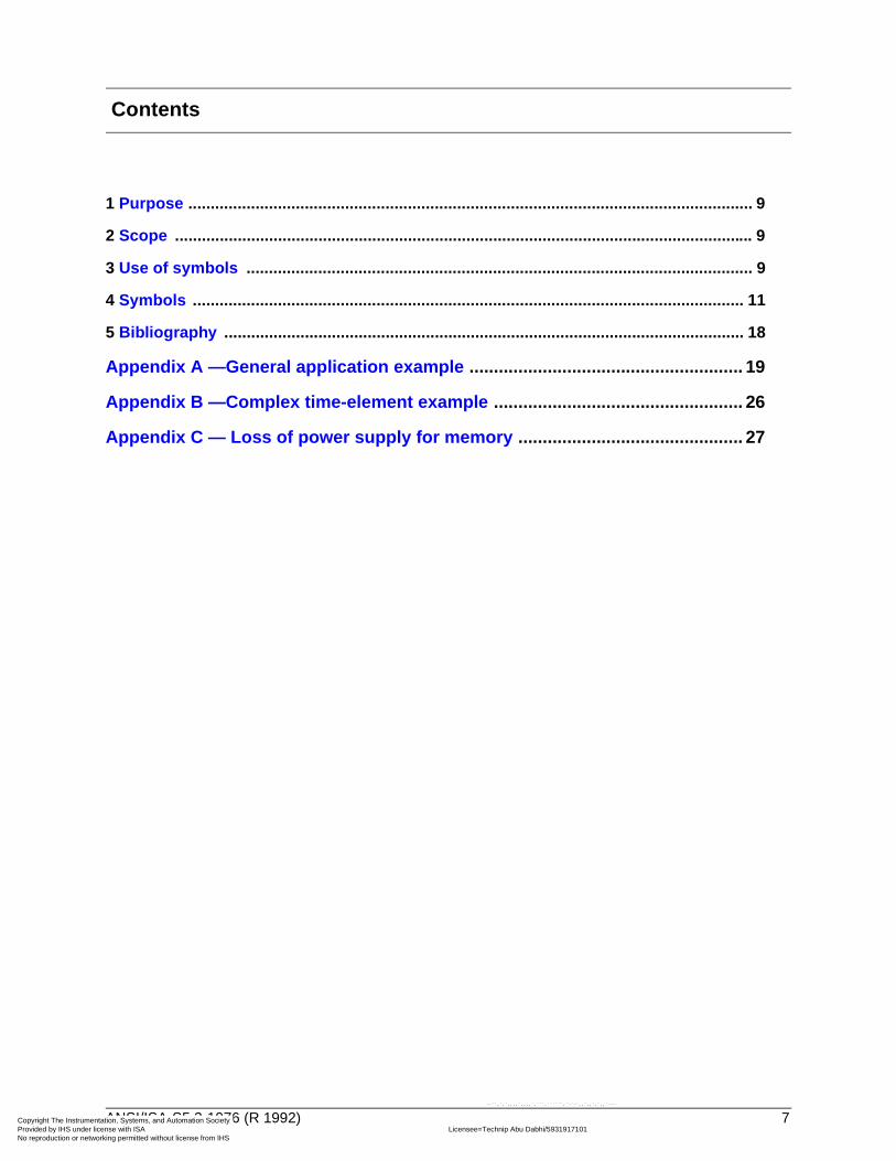
1 Purpose .............................................................................................................................. 9
2 Scope ................................................................................................................................. 9
3 Use of symbols ................................................................................................................. 9
4 Symbols ........................................................................................................................... 11
5 Bibliography .................................................................................................................... 18
Appendix A —General application example ........................................................ 19
Appendix B —Complex time-element example ................................................... 26
Appendix C — Loss of power supply for memory .............................................. 27
ANSI/ISA-S5.2-1976 (R 1992) 7
ntation, Systems, and Automation Society license with ISA Licensee=Technip Abu Dabhi/5931917101
Not for Resale, 02/12/2006 06:01:14 MSTorking permitted without license from IHS
--``,`,`,,,,`,,,,`,```,``````,`-`-`,,`,,`,`,,`---

Copyright The Instrumentation, Systems, and Automation Society Provided by IHS under license with ISA Licensee=Technip Abu Dabhi/5931917101
Not for Resale, 02/12/2006 06:01:14 MSTNo reproduction or networking permitted without license from IHS
--``,`,`,,,,`,,,,`,```,``````,`-`-`,,`,,`,`,,`---
Copyright The InstrumeProvided by IHS under No reproduction or netw
1 Purpose
1.1 The purpose of this Standard is to provide a method of logic diagramming of binary interlock and sequencing systems for the startup, operation, alarm, and shutdown of equipment and pro-cesses in the chemical, petroleum, power generation, air conditioning, metal refining, and numer-ous other industries.
1.2 The Standard is intended to facilitate the understanding of the operation of binary systems, and to improve communications among technical, management, design, operating, and mainte-nance personnel concerned with the systems.
2 Scope
2.1 The Standard provides symbols, both basic and non-basic, for binary operating functions. The use of symbols in typical systems is illustrated in appendices.
2.2 The Standard is intended to symbolize the binary operating functions of a system in a manner that can be applied to any class of hardware, whether it be electronic, electrical, fluidic, pneumatic, hydraulic, mechanical, manual, optical, or other.
3 Use of symbols
3.1 By using the symbols designated as "basic," logic systems may be described with the use of only the most fundamental logic building blocks. The remaining symbols, not basic, are more comprehensive and enable logic systems to be diagrammed more concisely. Use of the non-basic symbols is optional.
3.2 A logic diagram may be more or less detailed depending on its intended use. The amount of detail in a logic diagram depends on the degree of refinement of the logic and on whether auxiliary, essentially non-logic, information is included.
As an example of refinement of detail: A logic system may have two opposing inputs, e.g., a command to open and a command to close, which do not normally exist simultaneously; the logic diagram may or may not go so far as to specify the outcome if both the commands were to exist at the same time. In addition, explanatory notes may be added to the diagram to record the logic rationale.
Non-logic information may also be added, if desired, e.g., reference document identification, tag numbers, terminal markings, etc.
In these ways, the diagram may provide the level of detail appropriate, for example, for communication between a designer of pneumatic circuits and a designer of electric circuits, or may provide a broad-view system-description for a plant manager.
ANSI/ISA-S5.2-1976 (R 1992) 9
ntation, Systems, and Automation Society license with ISA Licensee=Technip Abu Dabhi/5931917101
Not for Resale, 02/12/2006 06:01:14 MSTorking permitted without license from IHS
--``,`,`,,,,`,,,,`,```,``````,`-`-`,,`,,`,`,,`---
Copyright The InstrumeProvided by IHS under No reproduction or netw
--``,`,`,,,,`,,,,`,```,``````,`-`-`,,`,,`,`,,`---
3.3 The existence of a logic signal may correspond physically to either the existence or the non-existence of an instrument signal, depending on the particular type of hardware system and the circuit design philosophy that are selected.* For example, a high-flow alarm may be chosen to be actuated by an electric switch whose contacts open on high flow; on the other hand, the high-flow alarm may be designed to be actuated by an electric switch whose contacts close on high flow. Thus, the high-flow condition may be represented physically by the absence of an electric signal or by the presence of the electric signal. The Standard does not attempt to relate the logic signal to an instrument signal of any specific kind.
3.4 A logic symbol that is shown in Section 4 with three inputs — A, B, and C — is typical for the logic function having any number of two or more inputs.
3.5 The flow of intelligence is represented by lines that interconnect logic statements. The normal direction of flow is from left to right, or top to bottom. Arrowheads may be added to the flow lines wherever needed for clarity, and shall be added to lines whose flow is not in a normal direction.
3.6 A summary of the status of an operating system may be put in the diagram wherever it is deemed useful as a reference point or landmark in the sequence.
3.7 There may be misunderstanding of binary logic statements involving devices that are not recognizable as inherently having only two specific alternative states. For example, if it is stated that a valve is not closed, this could mean either (a) that the valve is open fully, or (b) that the valve is simply not closed, namely, that it may be in any position from almost closed to wide open. To aid accurate communication between writer and reader of the logic diagram, the diagram should be interpreted literally. Therefore, possibility (b) is the correct one.
If a valve is an open-close valve, then, to avoid misunderstanding, it is necessary to do one of the following:
1) Develop the logic diagram in such a way that it says exactly what is intended. If the valve is intended to be open, then it should be so stated and not be stated as being not closed.
2) Have a separate note specifying that the valve always assumes either the closed or the open position.
By contrast, a device such as a motor-driven pump is either operating or stopped, barring some special situations. To say that the pump is not operating usually clearly denotes that it has stopped.
The following definitions apply to devices that have open, closed, or intermediate positions. The positions stated are nominal to the extent that there are differential-gap and dead band in the instrument that senses the position of the device.
Open position: a position that is 100-percent open.
Not-open position: a position that is less than 100-percent open. A device that is not open may or may not be closed.
Closed position: a position that is zero-percent open.
*In process operations, binary instrument signals are commonly either ON or OFF. However, as a more general case, logic systems exist that make use of binary hardware having signals with two alternate real values, e.g., +5 volts and –3 volts. In positive logic, the more positive signal, +5 volts, represents the existence of a logic condition, e.g., pump stopped. In negative logic, the less positive signal, –3 volts, represents the existence of a logic condition of pump stopped.
10 ANSI/ISA-S5.2-1976 (R 1992)
ntation, Systems, and Automation Society license with ISA Licensee=Technip Abu Dabhi/5931917101
Not for Resale, 02/12/2006 06:01:14 MSTorking permitted without license from IHS
Copyright The InstrumeProvided by IHS under No reproduction or netw
Not-closed position: a position that is more than zero-percent open. A device that is not closed may or may not be open.
Intermediate position: a SPECIFIED position that is greater than zero- and less than 100-percent open.
Not-at-intermediate position: a position that is either above or below the SPECIFIED intermediate position.
For a logic system having an input statement that is derived inferentially or indirectly, a condition may arise that will lead to an erroneous conclusion. For example, an assumption that flow exists because a pump motor is energized may be false because of a closed valve, a broken shaft, or other mishap. Factual statements, that is, statements based on positive measurements that a certain condition specifically exists or does not exist, are generally more reliable.
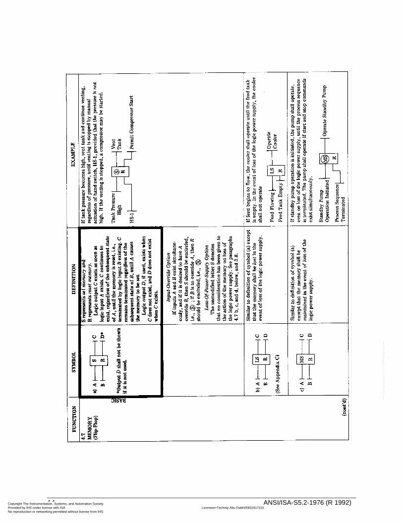
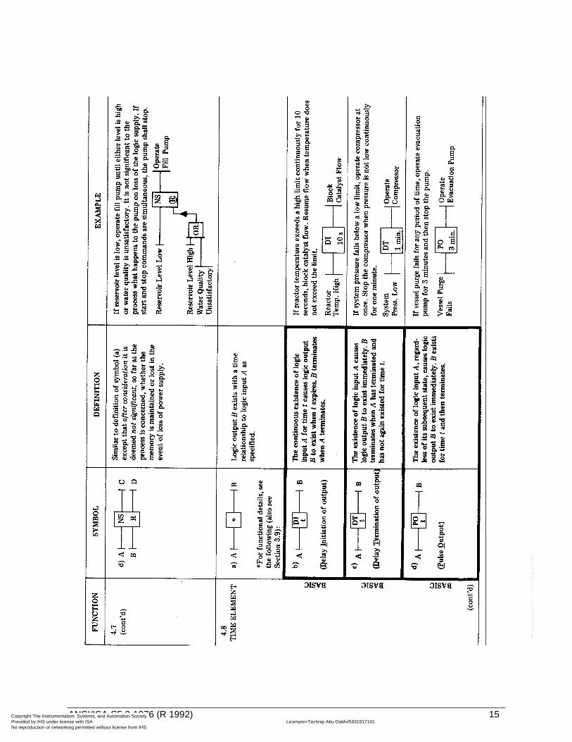
3.8 A process operation may be affected by loss of the power supply* to memories and to other logic elements. In order to take such operating eventualities into account, it may therefore be necessary to consider the effect of loss of power to any logic component or to the entire logic system. In such cases, it may be necessary to enter power supply or loss of power supply as logic inputs to a system or to individual logic elements. For memories, the consideration of power supply may be handled in this manner or as shown in Sections 4.7b, c, and d.
By the same token, it may be necessary to consider the effect of restoration of power supply.
Logic diagrams do not necessarily have to cover the effect of logic power supplies on process systems but may do so for thoroughness.
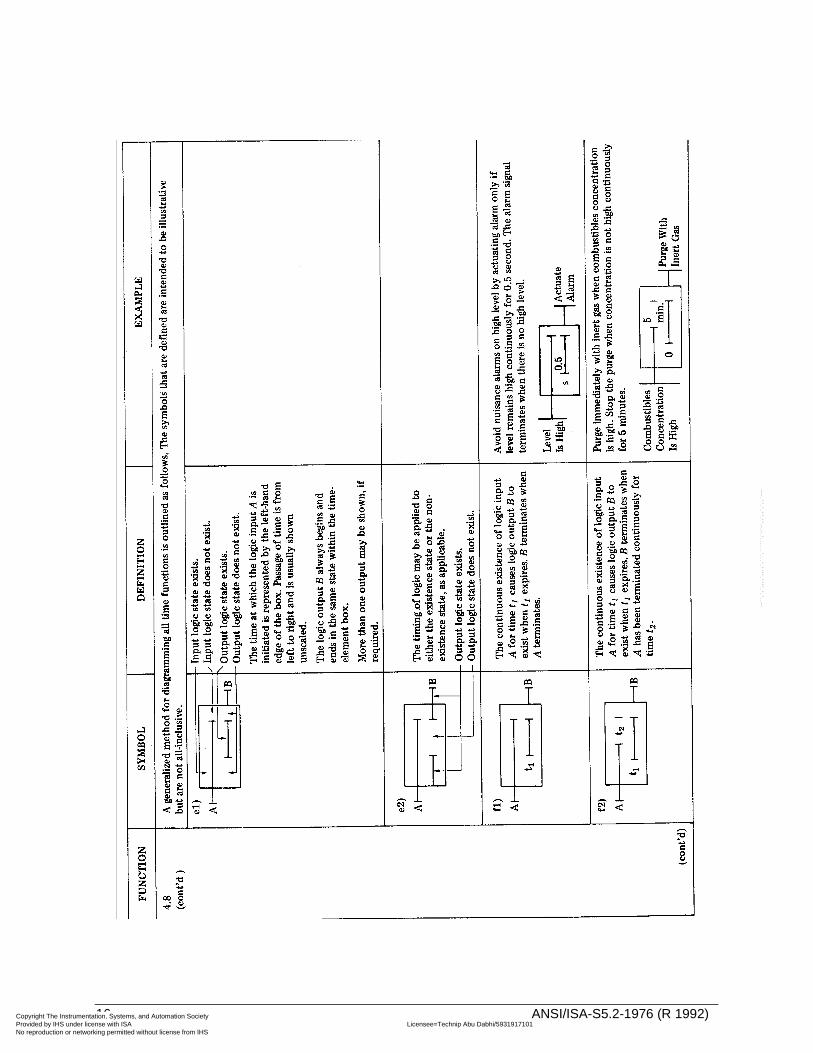
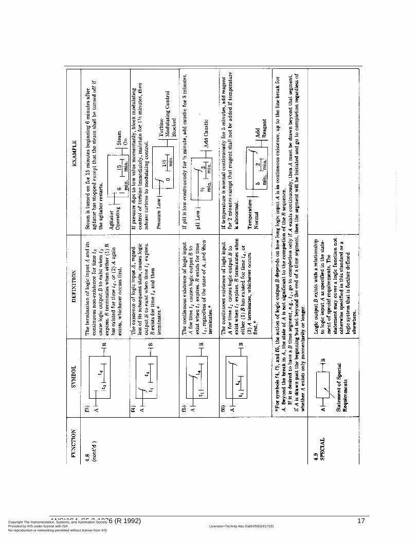
3.9 It is recommended, for clarity, that a single time-function symbol, as appropriate, be used to represent each time function in its entirety. Though not incorrect, the representation of a complex or uncommon time function by using a time-function symbol in immediate sequence with a second time-function symbol or with a NOT symbol should be avoided (see Section 4.8).
3.10 Process instrument symbols and designations follow ISA Standard S5.1-1973 (American National Standards Institute Standard Y32.20-1975), "Instrumentation Symbols and Designations." However, these symbols are included for illustrative purposes, only, and are not part of Standard S5.2.
3.11 If a drawing, or set of drawings, uses graphic symbols that are similar or identical to one another in shape or configuration and that have different meanings because they are taken from different standards, then adequate steps shall be taken to avoid misinterpretation of the symbols used. These steps may be to use caution notes or reference notes, comparison charts that illustrate and define the conflicting symbols, or other suitable means. This requirement is especially critical if the graphic symbols used, being from different disciplines, represent devices, conductors, flow lines, or signals whose symbols, if misinterpreted, may result in danger to personnel or damage to equipment.
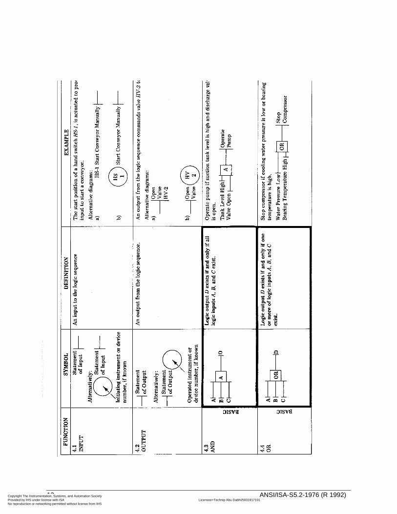
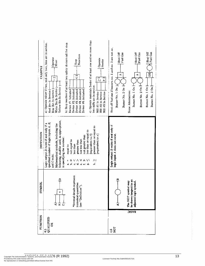
4 Symbols
The symbols for diagramming binary logic are defined as follows:
*The term power supply covers the energizing medium, whether it be electric, pneumatic, or other.--``,`,`,,,,`,,,,`,```,``````,`-`-`,,`,,`,`,,`---
ANSI/ISA-S5.2-1976 (R 1992) 11
ntation, Systems, and Automation Society license with ISA Licensee=Technip Abu Dabhi/5931917101
Not for Resale, 02/12/2006 06:01:14 MSTorking permitted without license from IHS
Copyright The InstrumeProvided by IHS under No reproduction or netw
--``,`,`,,,,`,,,,`,```,``````,`-`-`,,`,,`,`,,`---
12 ANSI/ISA-S5.2-1976 (R 1992)
ntation, Systems, and Automation Society license with ISA Licensee=Technip Abu Dabhi/5931917101
Not for Resale, 02/12/2006 06:01:14 MSTorking permitted without license from IHS
Copyright The InstrumeProvided by IHS underNo reproduction or netw
--``,`,`,,,,`,,,,`,```,``````,`-`-`,,`,,`,`,,`---
ANSI/ISA-S5.2-1976 (R 1992) 13
ntation, Systems, and Automation Society license with ISA Licensee=Technip Abu Dabhi/5931917101
Not for Resale, 02/12/2006 06:01:14 MSTorking permitted without license from IHS
Copyright The InstrumeProvided by IHS under No reproduction or netw
--``,`,`,,,,`,,,,`,```,``````,`-`-`,,`,,`,`,,`---
14 ANSI/ISA-S5.2-1976 (R 1992)
ntation, Systems, and Automation Society license with ISA Licensee=Technip Abu Dabhi/5931917101
Not for Resale, 02/12/2006 06:01:14 MSTorking permitted without license from IHS
Copyright The InstrumeProvided by IHS underNo reproduction or netw
--``,`,`,,,,`,,,,`,```,``````,`-`-`,,`,,`,`,,`---
ANSI/ISA-S5.2-1976 (R 1992) 15
ntation, Systems, and Automation Society license with ISA Licensee=Technip Abu Dabhi/5931917101
Not for Resale, 02/12/2006 06:01:14 MSTorking permitted without license from IHS
Copyright The InstrumeProvided by IHS under No reproduction or netw
--``,`,`,,,,`,,,,`,```,``````,`-`-`,,`,,`,`,,`---
16 ANSI/ISA-S5.2-1976 (R 1992)
ntation, Systems, and Automation Society license with ISA Licensee=Technip Abu Dabhi/5931917101
Not for Resale, 02/12/2006 06:01:14 MSTorking permitted without license from IHS
Copyright The InstrumeProvided by IHS underNo reproduction or netw
--``,`,`,,,,`,,,,`,```,``````,`-`-`,,`,,`,`,,`---
ANSI/ISA-S5.2-1976 (R 1992) 17
ntation, Systems, and Automation Society license with ISA Licensee=Technip Abu Dabhi/5931917101
Not for Resale, 02/12/2006 06:01:14 MSTorking permitted without license from IHS
Copyright The InstrumeProvided by IHS under No reproduction or netw
--``,`,`,,,,`,,,,`,```,``````,`-`-`,,`,,`,`,,`---
5 Bibliography
American National Standards Institute Standard Y32.14-1973, Graphic Symbols for Logic Diagrams (Two-State Devices).
American National Standards Institute Standard X3.5-1970, Flowchart Symbols and Their Usage in Information Processing.
International Electrotechnical Commission Recommendation, Publication 117-15, 1972, Binary Logic Elements.
National Electric Manufacturers Association Standard ICS 1-102, Graphic Symbols for Logic Diagrams.
National Electric Manufacturers Association Standard ICS 1-103, Static Switching Control Devices.
National Fluid Power Association Standard T.3.7.68.2, Graphic Symbols for Fluidic Devices and Circuits.
18 ANSI/ISA-S5.2-1976 (R 1992)
ntation, Systems, and Automation Society license with ISA Licensee=Technip Abu Dabhi/5931917101
Not for Resale, 02/12/2006 06:01:14 MSTorking permitted without license from IHS
Copyright The InstrumeProvided by IHS under No reproduction or netw
--``,`,`,,,,`,,,,`,```,``````,`-`-`,,`,,`,`,,`---
Appendix A General application example
A.1 Introduction
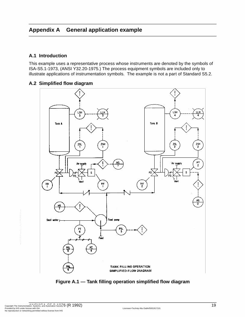
This example uses a representative process whose instruments are denoted by the symbols of ISA-S5.1-1973, (ANSI Y32.20-1975.) The process equipment symbols are included only to illustrate applications of instrumentation symbols. The example is not a part of Standard S5.2.
A.2 Simplified flow diagram
Figure A.1 — Tank filling operation simplified flow diagram
ANSI/ISA-S5.2-1976 (R 1992) 19
ntation, Systems, and Automation Society license with ISA Licensee=Technip Abu Dabhi/5931917101
Not for Resale, 02/12/2006 06:01:14 MSTorking permitted without license from IHS
Copyright The InstrumeProvided by IHS under No reproduction or netw
--``,`,`,,,,`,,,,`,```,``````,`-`-`,,`,,`,`,,`---
A.3 Word description
A.3.1 Pump start
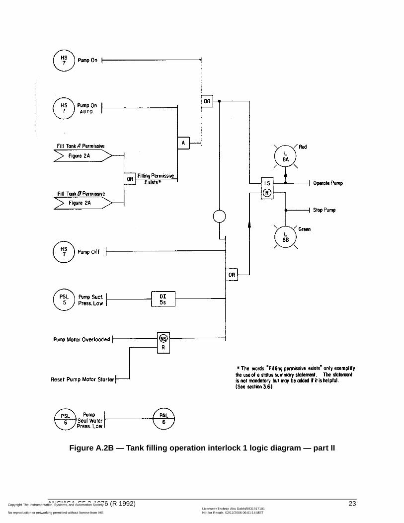
Feed is pumped into either tank A or tank B. The pump may be operated manually or automatically, as selected manually on a local maintained-output selector switch, HS-7, which has three positions: ON, OFF, and AUTO. When the pump is operating, red pilot light L-8A is on; when not operating, green pilot light L-8B is on. Once started, the pump continues to operate until a stopping command exists or until the control power supply is lost.
The pump may be operated manually at any time provided that no trouble condition exists: The suction pressure must not be low; the seal water pressure must not be low; and the pump motor must not be overloaded and its starter must be reset.
In order to operate the pump automatically, all the following conditions must be met:
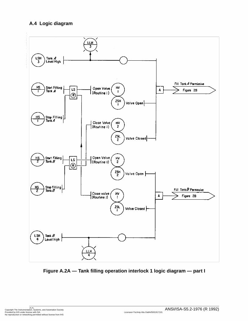
A.3.1.1 Board-mounted electric momentary-contact hand switches, HS-1 and HS-2, start the filling operation for tanks A and B, respectively. Each switch has two positions, START and STOP. START de-energizes the associated solenoid valves, HY-1 and HY-2. De-energizing a solenoid valve causes it to go to the fail-safe position, i.e., to vent. This depressurizes the pneumatic actuator of the associated control valves, HV-1 and HV-2. Depressurizing a control valve causes it to go to the fail-safe position, i.e., to open. The control valves have associated open-position switches, ZSH-1 and ZSH-2, and closed-position switches, ZSL-1 and ZSL-2.
The STOP position of switches HS-1 and HS-2 causes the opposite actions to occur so that the solenoid valves are energized, the control valve actuators are pressurized, and the control valves close.
If starting circuit power is lost, the starting memory is lost and the filling operation stops. The command to stop filling can override the command to start filling.
To start the pump automatically, either control valve HV-1 or HV-2 must be open and the other control valve must be closed, depending on whether tank A or tank B is to be filled.
A.3.1.2 The pump suction pressure must be above a given value, as signalled by pressure switch PSL-5.
A.3.1.3 If valve HV-1 is open to permit pumping into tank A, the tank level must be below a given value, as signalled by level switch LSH-3, which also actuates a board-mounted high-level pilot light, LLH-3. Similarly, high-level switch, LSH-4, permits pumping into tank B, if not actuated, and actuates pilot light LLH-4, if actuated.
A.3.1.4 Pump seal water pressure must be adequate, as indicated on board-mounted receiver gage, PI-6. This is a non-interlocked requirement that depends on the operator's attention before he starts the operation. Pressure switch, PSL-6, behind the board, actuates board-mounted low-pressure alarm, PAL-6.
A.3.1.5 The pump drive motor must not be overloaded and its starter must be reset.
A.3.2 Pump stop
The pump stops if any of the following conditions exists:
A.3.2.1 While pumping into a tank, its control valve leaves the fully-open position, or the valve of the other tank leaves its fully-closed position, provided that the pump is on automatic control.
20 ANSI/ISA-S5.2-1976 (R 1992)
ntation, Systems, and Automation Society license with ISA Licensee=Technip Abu Dabhi/5931917101
Not for Resale, 02/12/2006 06:01:14 MSTorking permitted without license from IHS
Copyright The InstrumeProvided by IHS under No reproduction or netw
--``,`,`,,,,`,,,,`,```,``````,`-`-`,,`,,`,`,,`---
A.3.2.2 The tank selected for filling becomes full, provided that the pump is on automatic control.
A.3.2.3 The pump suction pressure is continuously low for 5 seconds.
A.3.2.4 The pump drive motor is overloaded. It is immaterial to the process logic whether or not the memory of the pump motor overload is retained on loss of power in this system because the maintained memory that operates the pump is defined as losing memory on loss of power, and this by itself will cause the pump to stop. However, an existing motor-overload condition prevents the motor starter from being reset.
A.3.2.5 The sequence is stopped manually through HS-1 or HS-2. If stop and start commands for pump operation exist simultaneously, then the stop command overrides the operate command.
A.3.2.6 The pump is stopped manually by HS-7.
A.3.2.7 The pump seal water pressure is low. This condition is not interlocked, and requires manual intervention to stop the pump.
ANSI/ISA-S5.2-1976 (R 1992) 21
ntation, Systems, and Automation Society license with ISA Licensee=Technip Abu Dabhi/5931917101
Not for Resale, 02/12/2006 06:01:14 MSTorking permitted without license from IHS
Copyright The InstrumeProvided by IHS under No reproduction or netw
A.4 Logic diagram
Figure A.2A — Tank filling operation interlock 1 logic diagram — part I
--``,`,`,,,,`,,,,`,```,``````,`-`-`,,`,,`,`,,`---
22 ANSI/ISA-S5.2-1976 (R 1992)
ntation, Systems, and Automation Society license with ISA Licensee=Technip Abu Dabhi/5931917101
Not for Resale, 02/12/2006 06:01:14 MSTorking permitted without license from IHS
Copyright The InstrumeProvided by IHS under No reproduction or netw
--``,`,`,,,,`,,,,`,```,``````,`-`-`,,`,,`,`,,`---
Figure A.2B — Tank filling operation interlock 1 logic diagram — part II
ANSI/ISA-S5.2-1976 (R 1992) 23
ntation, Systems, and Automation Society license with ISA Licensee=Technip Abu Dabhi/5931917101
Not for Resale, 02/12/2006 06:01:14 MSTorking permitted without license from IHS
Copyright The InstrumeProvided by IHS under No reproduction or netw
--``,`,`,,,,`,,,,`,```,``````,`-`-`,,`,,`,`,,`---
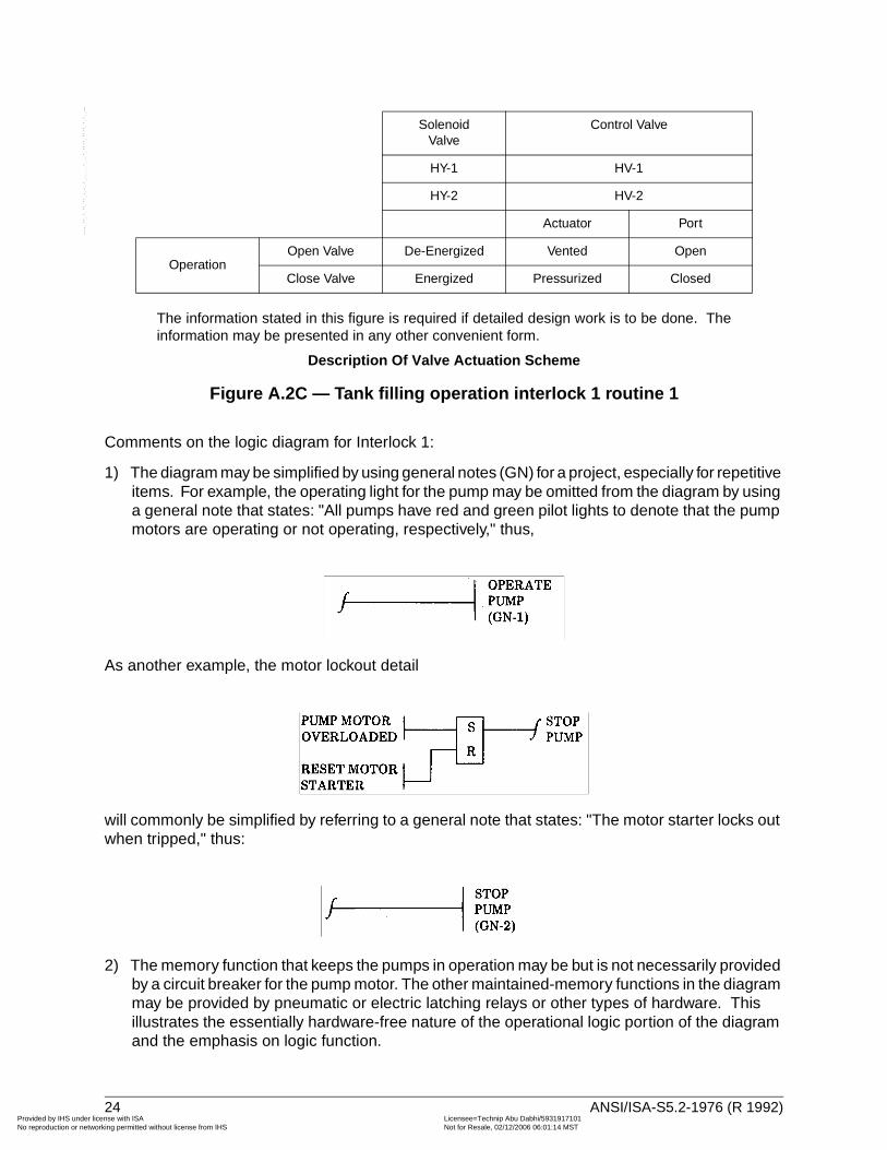
The information stated in this figure is required if detailed design work is to be done. Theinformation may be presented in any other convenient form.
Description Of Valve Actuation Scheme
Figure A.2C — Tank filling operation interlock 1 routine 1
Comments on the logic diagram for Interlock 1:
1) The diagram may be simplified by using general notes (GN) for a project, especially for repetitive items. For example, the operating light for the pump may be omitted from the diagram by using a general note that states: "All pumps have red and green pilot lights to denote that the pump motors are operating or not operating, respectively," thus,
As another example, the motor lockout detail
will commonly be simplified by referring to a general note that states: "The motor starter locks out when tripped," thus:
2) The memory function that keeps the pumps in operation may be but is not necessarily provided by a circuit breaker for the pump motor. The other maintained-memory functions in the diagram may be provided by pneumatic or electric latching relays or other types of hardware. This illustrates the essentially hardware-free nature of the operational logic portion of the diagram and the emphasis on logic function.
SolenoidValve
Control Valve
HY-1 HV-1
HY-2 HV-2
Actuator Port
OperationOpen Valve De-Energized Vented Open
Close Valve Energized Pressurized Closed
24 ANSI/ISA-S5.2-1976 (R 1992)
ntation, Systems, and Automation Society license with ISA Licensee=Technip Abu Dabhi/5931917101
Not for Resale, 02/12/2006 06:01:14 MSTorking permitted without license from IHS
Copyright The InstrumeProvided by IHS under No reproduction or netw
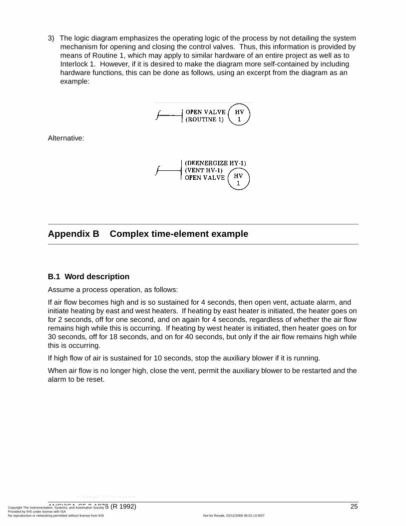
3) The logic diagram emphasizes the operating logic of the process by not detailing the system mechanism for opening and closing the control valves. Thus, this information is provided by means of Routine 1, which may apply to similar hardware of an entire project as well as to Interlock 1. However, if it is desired to make the diagram more self-contained by including hardware functions, this can be done as follows, using an excerpt from the diagram as an example:
Alternative:
Appendix B Complex time-element example
B.1 Word description
Assume a process operation, as follows:
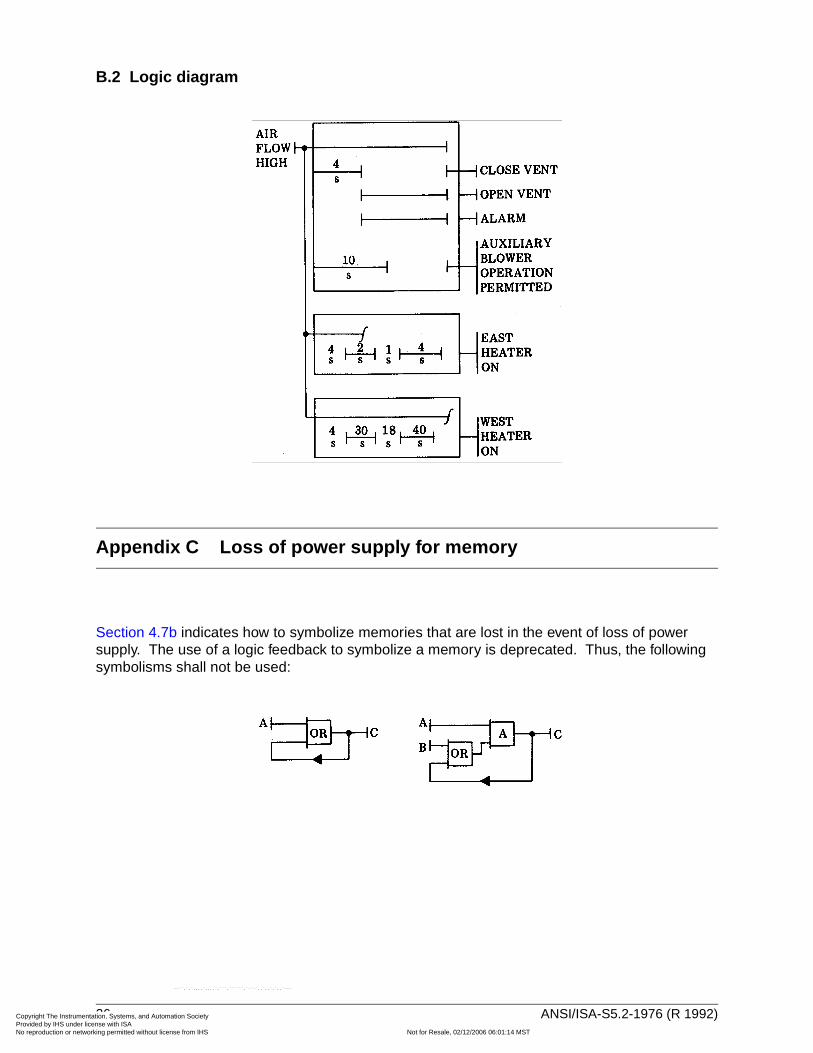
If air flow becomes high and is so sustained for 4 seconds, then open vent, actuate alarm, and initiate heating by east and west heaters. If heating by east heater is initiated, the heater goes on for 2 seconds, off for one second, and on again for 4 seconds, regardless of whether the air flow remains high while this is occurring. If heating by west heater is initiated, then heater goes on for 30 seconds, off for 18 seconds, and on for 40 seconds, but only if the air flow remains high while this is occurring.
If high flow of air is sustained for 10 seconds, stop the auxiliary blower if it is running.
When air flow is no longer high, close the vent, permit the auxiliary blower to be restarted and the alarm to be reset.
ANSI/ISA-S5.2-1976 (R 1992) 25
ntation, Systems, and Automation Society license with ISA Licensee=Technip Abu Dabhi/5931917101
Not for Resale, 02/12/2006 06:01:14 MSTorking permitted without license from IHS
--``,`,`,,,,`,,,,`,```,``````,`-`-`,,`,,`,`,,`---
Copyright The InstrumeProvided by IHS under No reproduction or netw
B.2 Logic diagram
Appendix C Loss of power supply for memory
Section 4.7b indicates how to symbolize memories that are lost in the event of loss of power supply. The use of a logic feedback to symbolize a memory is deprecated. Thus, the following symbolisms shall not be used:
--``,`,`,,,,`,,,,`,```,``````,`-`-`,,`,,`,`,,`---
26 ANSI/ISA-S5.2-1976 (R 1992)
ntation, Systems, and Automation Society license with ISA Licensee=Technip Abu Dabhi/5931917101
Not for Resale, 02/12/2006 06:01:14 MSTorking permitted without license from IHS

Copyright The InstrumeProvided by IHS under No reproduction or netw
--``,`,`,,,,`,,,,`,```,``````,`-`-`,,`,,`,`,,`---
ANSI/ISA-S5.2-1976 (R 1992) 27
ntation, Systems, and Automation Society license with ISA Licensee=Technip Abu Dabhi/5931917101
Not for Resale, 02/12/2006 06:01:14 MSTorking permitted without license from IHS
Developing and promulgating technically sound consensus standards, recommended practices, and technical reports is one of ISA's primary goals. To achieve this goal the Standards and Practices Department relies on the technical expertise and efforts of volunteer committee members, chairmen, and reviewers.
ISA is an American National Standards Institute (ANSI) accredited organization. ISA administers United States Technical Advisory Groups (USTAGs) and provides secretariat support for International Electrotechnical Commission (IEC) and International Organization for Standardization (ISO) committees that develop process measurement and control standards. To obtain additional information on the Society's standards program, please write:
ISAAttn: Standards Department67 Alexander DriveP.O. Box 12277Research Triangle Park, NC 27709
ISBN: 0-87664-331-4
Copyright The Instrumentation, Systems, and Automation Society Provided by IHS under license with ISA Licensee=Technip Abu Dabhi/5931917101
Not for Resale, 02/12/2006 06:01:14 MSTNo reproduction or networking permitted without license from IHS
--``,`,`,,,,`,,,,`,```,``````,`-`-`,,`,,`,`,,`---
Related Documents


