1 Radio Network Tuning and Optimization for Universal Mobile Telecommunications System (UMTS) Osama Bilal Thesis Worker Ericsson Finland

Welcome message from author
This document is posted to help you gain knowledge. Please leave a comment to let me know what you think about it! Share it to your friends and learn new things together.
Transcript
1
Radio Network Tuning and Optimization for Universal Mobile Telecommunications
System (UMTS)
Osama Bilal Thesis Worker Ericsson Finland
2
Radio Network Tunning and Optimization for UMTS
Author: Osama BilalSupervisor: Prof. Sven-Gustav Häggman Instructor: B.Sc. Jukka Möykkynen
Carried out for Ericsson FinlandTuning Activity for a UMTS Operator
3
AGENDA
• Motivation• 2G-3G, What is different• Tuning Process Flow• Tools used for Tuning Activity• Equipments Configuration• Pilot Tuning• UE Tuning • Final Words

4
MOTIVATION
• 3G networks are becoming commercially available all over the world
• To check the functionality of the networks before commercial launch
• Network designs are based on propagations models and simulations (coverage verification)
• 3G technology (WCDMA) is different from 2G• Tools and methods for 3G Networks
5
Differences compared to 2G• In General- The Technology is more complicated (Overlapping cells, soft hand over, power control, cell breathing etc)
- High performance requirements on products (UE & Network nodes)
- In Particular for Tuning & Optimzation- Process & tools are under development- Co-located GSM/3G sites- Shared Antenna System- Inter-working with GSM
6
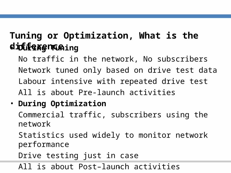
Tuning or Optimization, What is the difference• During TuningNo traffic in the network, No subscribersNetwork tuned only based on drive test dataLabour intensive with repeated drive testAll is about Pre-launch activities
• During OptimizationCommercial traffic, subscribers using the networkStatistics used widely to monitor network performanceDrive testing just in caseAll is about Post–launch activities

7
Tuning Process Flow
Radio Network Initial Tuning for WCDMA
Preparations Param eter Audit
Com m ercial Launch
Drive Testing & Post
Processing
Change Verification & Reporting
Analysis & Change Proposals
8
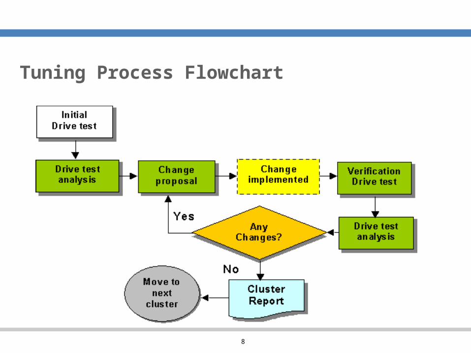
Tuning Process Flowchart
9
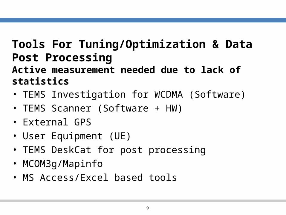
Tools For Tuning/Optimization & Data Post ProcessingActive measurement needed due to lack of statistics• TEMS Investigation for WCDMA (Software)• TEMS Scanner (Software + HW)• External GPS• User Equipment (UE)• TEMS DeskCat for post processing• MCOM3g/Mapinfo• MS Access/Excel based tools
10
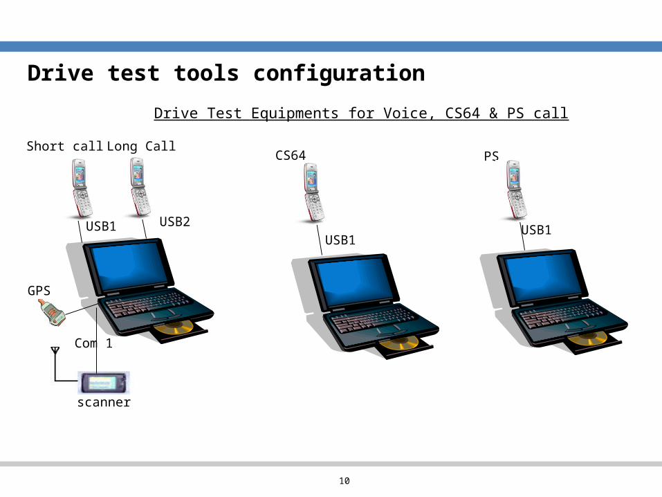
USB2 USB1
Com 1
scanner
Short call Long Call
USB1
CS64
GPS
USB1
PS
Drive Test Equipments for Voice, CS64 & PS call
Drive test tools configuration
11
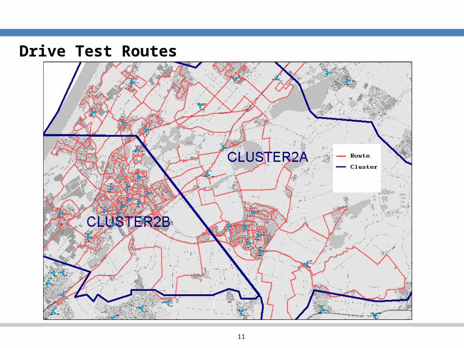
Drive Test Routes
12
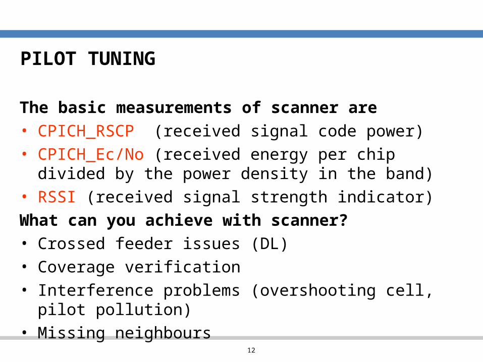
PILOT TUNING
The basic measurements of scanner are • CPICH_RSCP (received signal code power)• CPICH_Ec/No (received energy per chip divided by the power density in the band)
• RSSI (received signal strength indicator)What can you achieve with scanner?• Crossed feeder issues (DL) • Coverage verification• Interference problems (overshooting cell, pilot pollution)
• Missing neighbours
13
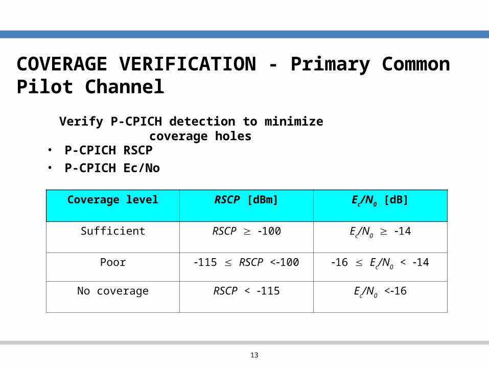
COVERAGE VERIFICATION - Primary Common Pilot Channel
Verify P-CPICH detection to minimize coverage holes
• P-CPICH RSCP• P-CPICH Ec/No
Coverage level RSCP [dBm] Ec/N0 [dB]
Sufficient RSCP 100 Ec/N0 14
Poor 115 RSCP <100 16 Ec/N0 < 14
No coverage RSCP < 115 Ec/N0 <16

14
Best Server Signal Strength (RSCP)
• Yellow is good
• Blue can generate problems
• Grey is bad
15
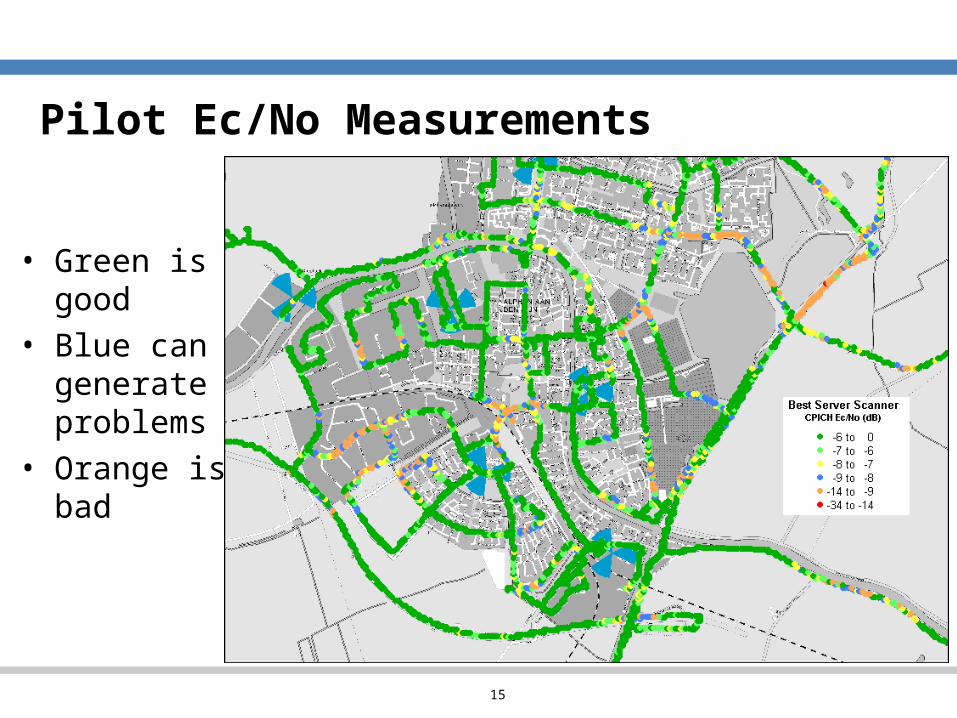
Pilot Ec/No Measurements
• Green is good
• Blue can generate problems
• Orange is bad
16
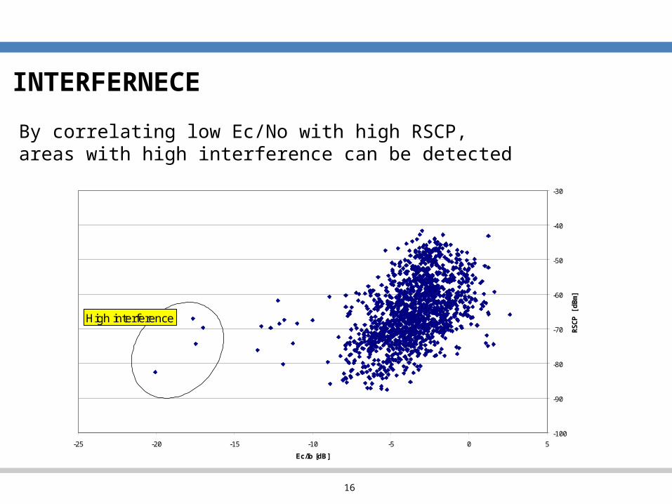
INTERFERNECE
-100
-90
-80
-70
-60
-50
-40
-30
-25 -20 -15 -10 -5 0 5Ec/Io [dB]
RSCP [dBm]
High interference
By correlating low Ec/No with high RSCP, areas with high interference can be detected
17
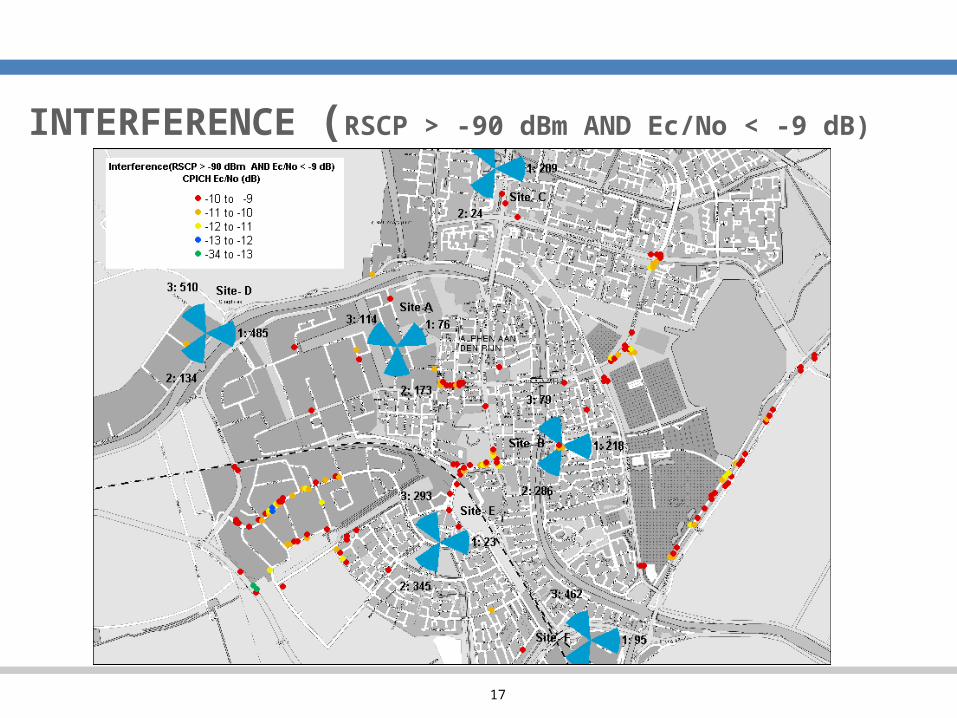
INTERFERENCE (RSCP > -90 dBm AND Ec/No < -9 dB)
18
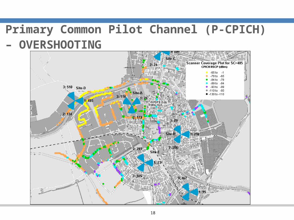
Primary Common Pilot Channel (P-CPICH) – OVERSHOOTING
19
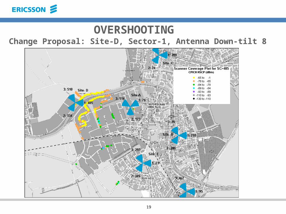
OVERSHOOTING Change Proposal: Site-D, Sector-1, Antenna Down-tilt 8
Degrees
20
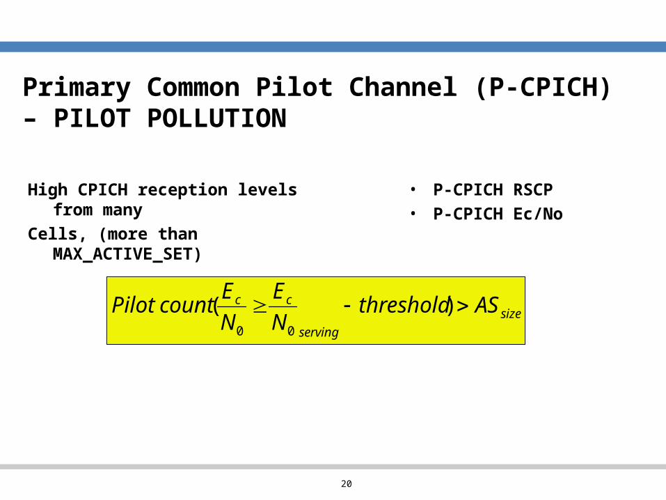
Primary Common Pilot Channel (P-CPICH) – PILOT POLLUTION
• P-CPICH RSCP• P-CPICH Ec/No
High CPICH reception levels from many
Cells, (more than MAX_ACTIVE_SET)
sizeserving
cc ASthresholdNE
NEcountPilot )(
00
21
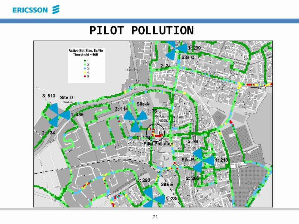
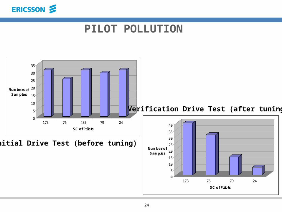
PILOT POLLUTION
22
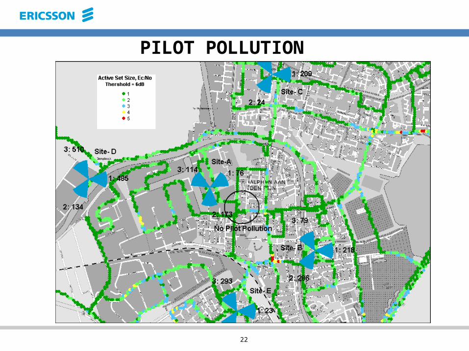
PILOT POLLUTION
23
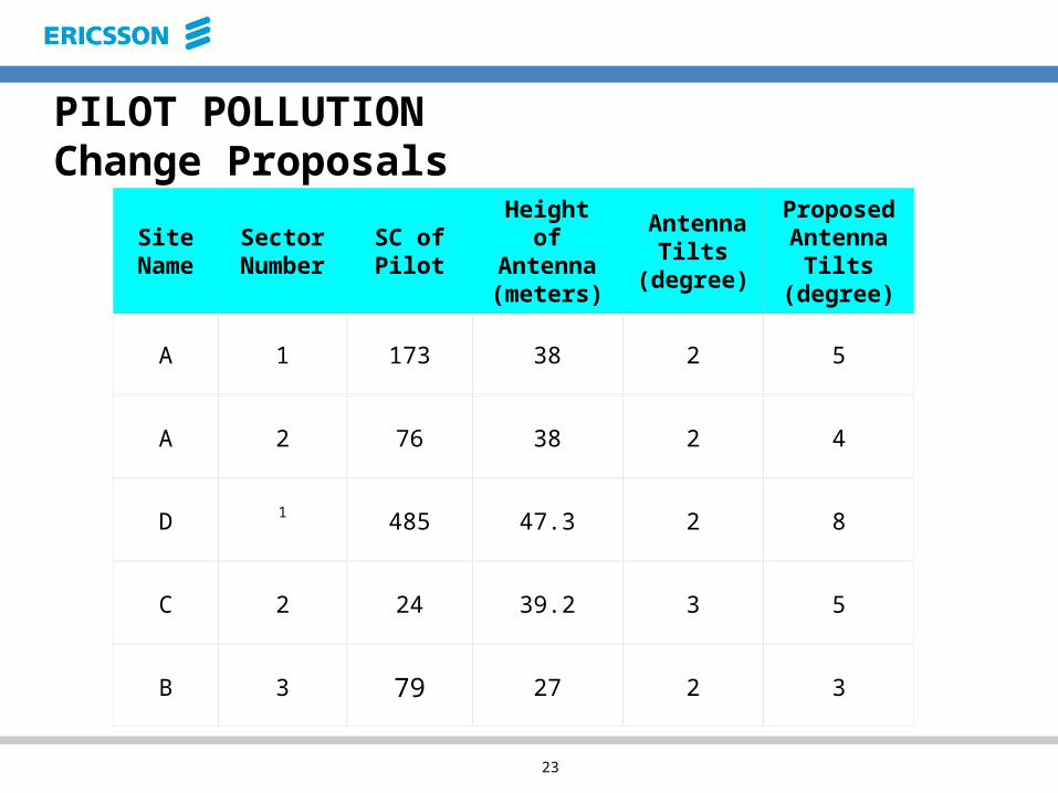
PILOT POLLUTIONChange Proposals
Site Name
Sector Number
SC of Pilot
Height of
Antenna (meters)
Antenna Tilts
(degree)
Proposed Antenna Tilts
(degree)
A 1 173 38 2 5
A 2 76 38 2 4
D 1 485 47.3 2 8
C 2 24 39.2 3 5
B 3 79 27 2 3
24
0
5
10
15
20
2530
35
Num bers of Sam ples
173 76 485 79 24SC of Pilots
0510152025303540
Num ber of Sam ples
173 76 79 24SC of Pilots
PILOT POLLUTION
Initial Drive Test (before tuning)
Verification Drive Test (after tuning)

25
UE TUNING
• Voice /Video/PS calls– Long calls– short calls
• Identify problem areas– Blocked calls– Dropped calls– Delay/Throughput
26
Short Calls Analysis
Set-up a call and maintain it for a pre-defined time duration
(for 15-60 s)
Call set-up failure and drops during short calls can be mainly
used to analysis Accessibility failure due to:
• UE Failure• Unsuitable Parameters Setting• Coverage Problem• Interference• Others
27
Long Calls Analysis
Drops during long call can be used to identify:
• Missing Neighbor Relation• Coverage Problem• UE Problems• Network Characteristics• Best Parameter Setting• Others
Set-up a call and maintain it until it is drop (used for the analysis of Retainability performace)
28
KEY PERFORMANCE INDICATORS
• Accessability (Call set-up success rate)• Retainability (Dropped calls)• Mobility (Handover success rate)• Integrity (BLER and throughput)
29
Case 1: Drop due to missing neighbor
Problem: Detected Nighbor (DN)• UE sends a Measurement Report that contains an event1a means adding a new RL (cell) to Active Set
• If the reported cell is not in the current neighbor cell list and the reported Ec/No is better than the best serving cell Ec/No in AS by some dBs (set by a RNC parameter)
• If for any reason the new cell can not be added to AS, call will be released
30
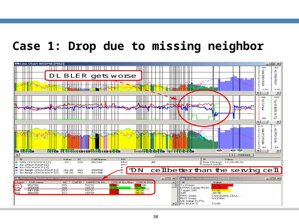
Case 1: Drop due to missing neighbor
“DN” cell better than the serving cell
DL BLER gets worse
“DN” cell better than the serving cell
DL BLER gets worse

31
Case 2: Drop due to Poor Coverage (low RSCP)Problem: Poor DL coverageWhen UE gets to an area with low RSCP ( < -105 dBm)
regardless Ec/No values there is high risk for drop.
UE will likely ramp up the transmitted power and reach its
max power. The DL BLER will probably increase and SIR
target cannot maintain anymore, finally the call drops.
32
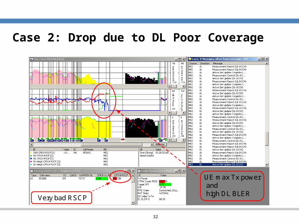
Case 2: Drop due to DL Poor Coverage
Very bad RSCP
UE m ax Tx powerandhigh DL BLERVery bad RSCP
UE m ax Tx powerandhigh DL BLER
33
Case 3:PS: Session Error due to Poor DL CoverageUE enters a very low coverage area (RSCP < – 105 dBm).
The packet connection is carried on a 64/64 DCH Channel
as consequence of the low coverage conditions.
The UE will likely ramp up its power to the maximum, goes
to Idle Mode and the Application and RLC throughputs go
to zero. At this point the RAS application will start the Session
Timeout timer, if the throughput is not resumed the Session
Error event is triggered with cause “session timeout”.

34
PS: Session Error due to Poor DL Coverage App throughput ~64kbps
Very low RSCP
App throughput ~64kbps
Very low RSCP
35
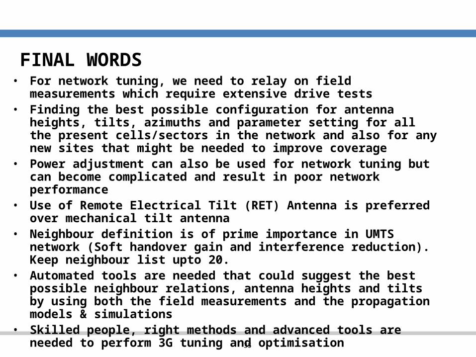
FINAL WORDS• For network tuning, we need to relay on field
measurements which require extensive drive tests• Finding the best possible configuration for antenna
heights, tilts, azimuths and parameter setting for all the present cells/sectors in the network and also for any new sites that might be needed to improve coverage
• Power adjustment can also be used for network tuning but can become complicated and result in poor network performance
• Use of Remote Electrical Tilt (RET) Antenna is preferred over mechanical tilt antenna
• Neighbour definition is of prime importance in UMTS network (Soft handover gain and interference reduction). Keep neighbour list upto 20.
• Automated tools are needed that could suggest the best possible neighbour relations, antenna heights and tilts by using both the field measurements and the propagation models & simulations
• Skilled people, right methods and advanced tools are needed to perform 3G tuning and optimisation
36
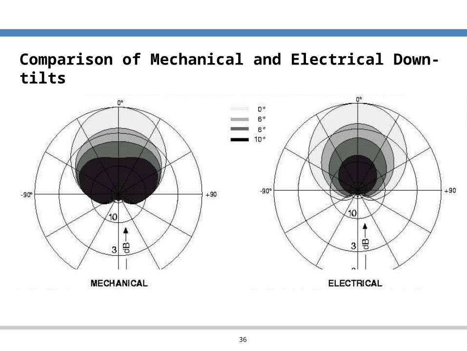
Comparison of Mechanical and Electrical Down-tilts
Related Documents